FAILURE ANALYSIS OF A DIFFERENTIAL GEAR PINION FOR...
12
Proceedings of the 5th International Conference on Integrity-Reliability-Failure, Porto/Portugal 24-28 July 2016 Editors J.F. Silva Gomes and S.A. Meguid Publ. INEGI/FEUP (2016) -1149- PAPER REF: 6200 (Invited Paper) FAILURE ANALYSIS OF A DIFFERENTIAL GEAR PINION FOR WHEEL LOADERS Dario Croccolo (*) , Massimiliano De Agostinis, Stefano Fini, Giorgio Olmi DIN - Department of Industrial Engineering, University of Bologna, Viale Risorgimento 2, 40136 Bologna (IT) (*) Email: [email protected] ABSTRACT The present paper deals with the failure analysis of a pinion shaft belonging to a differential gear for offroad machinery applications, namely wheel loaders. The motivations of the study arise from some in-field failures, which resulted in the fracture of the pinion shaft, originated at an external groove located at the end of its threaded portion. The issue has been tackled by means of analytical, numerical and experimental tools. The observed failures have been demonstrated to be due to the in-service loosening of a ring nut, whose function is to preload the tapered rolling bearings, which support the shaft. Keywords: Pinion shaft, differential gear, failure, ring nut, preloaded bearing. NOMENCLATURE T tightening torque [Nm] F v preload force [N] p thread pitch [-] d 2 pitch diameter [mm] D k mean diameter at the underhead [mm] µ m mean friction coefficient [-] M pinion input torque [Nm] p φ pressure angle for the pinion [deg] p Ψ spiral angle for the pinion [deg] p γ pinion pitch angle [deg] K t stress concentration factor [-] q notch sensitivity factor [-] K f fatigue concentration factor [-] UTS ultimate tensile strength [MPa] Sy yield strength [MPa]
-
Upload
phungkhuong -
Category
Documents
-
view
223 -
download
1
Transcript of FAILURE ANALYSIS OF A DIFFERENTIAL GEAR PINION FOR...

Proceedings of the 5th International Conference on Integrity-Reliability-Failure, Porto/Portugal 24-28 July 2016
Editors J.F. Silva Gomes and S.A. Meguid
Publ. INEGI/FEUP (2016)
-1149-
PAPER REF: 6200 (Invited Paper)
FAILURE ANALYSIS OF A DIFFERENTIAL GEAR PINION FOR
WHEEL LOADERS
Dario Croccolo(*)
, Massimiliano De Agostinis, Stefano Fini, Giorgio Olmi
DIN - Department of Industrial Engineering, University of Bologna, Viale Risorgimento 2, 40136 Bologna (IT) (*)Email: [email protected]
ABSTRACT
The present paper deals with the failure analysis of a pinion shaft belonging to a differential
gear for offroad machinery applications, namely wheel loaders. The motivations of the study
arise from some in-field failures, which resulted in the fracture of the pinion shaft, originated
at an external groove located at the end of its threaded portion. The issue has been tackled by
means of analytical, numerical and experimental tools. The observed failures have been
demonstrated to be due to the in-service loosening of a ring nut, whose function is to preload
the tapered rolling bearings, which support the shaft.
Keywords: Pinion shaft, differential gear, failure, ring nut, preloaded bearing.
NOMENCLATURE
T tightening torque [Nm]
Fv preload force [N]
p thread pitch [-]
d2 pitch diameter [mm]
Dk mean diameter at the underhead [mm]
µm mean friction coefficient [-]
M pinion input torque [Nm]
pφ pressure angle for the pinion [deg]
pΨ spiral angle for the pinion [deg]
pγ pinion pitch angle [deg]
Kt stress concentration factor [-]
q notch sensitivity factor [-]
Kf fatigue concentration factor [-]
UTS ultimate tensile strength [MPa]
Sy yield strength [MPa]

Symposium_17: Mechanical Connections
-1150-
INTRODUCTION
The studied pinion shaft transmits the torque from the engine to the drive wheels through the
crown wheel of the differential gear. It is supported during rotation by two tapered single row
rolling bearings that are axially preloaded by means of a ring nut, which in turn engages with
an external thread, cut into the shaft tail end. After tightening, the inner races of the bearings
come in contact by means of a sleeve and some laminated shims. The tightening operation is
performed in torque control, by means of an electric spindle. An observation of the fracture
surface of some failed shafts indicates that fracture always propagates along the cross section
of the shaft, whereas final fracture occurs on a 45° inclined surface with respect to the shaft
axis, as shown in Fig. 1. The inner splined that mates with the flywheel shaft is clearly visible
by the tail side of the pinion shaft. The position of the cross section where failure occurs is
well aligned along the shaft longitudinal axis to the groove at the end of the ring nut external
thread. It must be pointed out that other similar groups did not experience complete failure,
but an unexpected loosening of the ring nut, with resulting loss of bearing preload, was
observed. The occurrence of the described breakage was the main motivation for this study,
whose aim was to investigate the primary reason of the occurred failure. In addition, we
wanted to investigate if the observed ring nut loosening could be explained, based on the
actual loads on the shaft and if this occurrence may trigger the shaft complete failure. Finally,
we tried to indicate possible design improvements to overcome the described events.
Fig. 1 - Failed pinion shaft
MATERIALS AND METHODS
Some failed pinions shafts have been observed by an optical multifocus microscope, in order
to study the failure mechanism, as suggested by the approach followed in a previous study
(Croccolo, 2014). The static and fatigue dimensioning of the shaft has been assessed, under
the assumption that the bearings were preloaded properly. The analysis of the shaft has been
performed considering an ultimate tensile strength of the material UTS=850 MPa and a yield
stress Sy=630 MPa. The resistance against fatigue is assessed by means of the Haigh diagram.
In order to accomplish this task, the duty cycle of the wheel loader (Filla, 2013) has been
analyzed. The loads on the shaft have been evaluated, considering the powertrain geometry
and the well-known formulas for spiral bevel gears (Niemann, 2005; Timken, 2011).
Analytical and numerical analysis have been carried out, in order to estimate the stress
distribution generated by the preload at the threaded connection and the stress concentration

Proceedings of the 5th International Conference on Integrity-Reliability-Failure
-1151-
factor at the external groove at the end of the shaft threaded portion. The axial stiffness of the
tapered roller bearings was provided by the supplier (Timken, 2011). Lab tests have then been
performed with the aim of determining the mean friction coefficient in the screw connection
and the actual preload force generated upon the ring-nut tightening (Croccolo, 2012; De
Agostinis, 2015). The tightening force has been measured by an instrumented sleeve, where
strain gages (1-LY11-1,5/120 by Hottinger Baldwin Messtechnik, HBM, Germany) were
connected in a full Wheatstone Bridge. Data sampling was performed by a NI C-DAQ 9184
equipped by the bridge module NI 9237 at the frequency of 10 Hz. The same instrumented
sleeve, assembled to the shaft, was then used for a further lab experimentation. The aim of
this campaign was to get a full awareness about the bearing preload value and to assess if it
was sufficient to warrant external load withstanding. The performed test consisted in the
application of an external axial load over the pinion shaft, thus simulating the in-service load,
by a standing press (by Italsigma, Forlì, Italy) with a 100kN capacity. The load was on-line
measured and increased until the rear side bearing lost contact with its race, i.e. until the full
loss of the initial preload. This event was detected by the continuous monitoring of the load
on the instrumented sleeve: its constant trend after an initial increase indicated the loss of
preload. A numerical model was finally developed, in order to estimate the torsional loads
that, during the service, may be transmitted through the bearing inner races and the interposed
spacer to the ring nut and that are likely to be an additional reason for the preload loss.
RESULTS AND DISCUSSION
A careful study of the fracture surface indicates that fracture substantially propagates
perpendicularly with respect to the shaft axis. Considering an enlarged view of detail (1) of
Fig. 2, a nucleation point, where the crack is likely to have initiated, can be observed; similar
initiation points are visible in a number of teeth of the inner splined. The final fracture occurs
on a 45° angled surface, which is visible at the top of detail (2) shown in Fig. 2.
Fig. 2 - Shaft fracture surface

Symposium_17: Mechanical Connections
-1152-
Table 1 - Distribution of working conditions
CONDITION RATE TORQUE [Nm]
Digging 5% 1007
Y-cycle (short) 30% 943
Y-cycle (long) 27% 882
Load transport 25% 399
Dozing forward 5% 1767
Dozing reverse 2% -926
Roading 6% 397
On the other hand, fatigue crack initiation points have not been detected on the shaft external
surface. The maximum torque Tmax is transmitted to the shaft during forward shoveling.
However, this working condition is not highly frequent, considering the usual tasks performed
by excavators. Conversely, a typical use condition is that summarized by the working cycle in
Table 1 (Filla, 2013; Timken, 2011), where the torque average values are much lower,
approximately of 52%, respect to Tmax.
The loads acting on the shaft have been calculated by means of the well-known formulas
(Eqs. 1, 2 and 3) for spiral bevel gears reported in Fig 3.
Fig. 3 - Spiral bevel loads in the driving pinion (Timken, 2011)

Proceedings of the 5th International Conference on Integrity-Reliability-Failure
-1153-
mg
tpD
MF
2= (1)
)cossinsin(tancos
pppp
p
tp
ap
FF γγφ Ψ+
Ψ= (2)
)sinsincos(tancos
pppp
p
tp
ap
FF γγφ Ψ−
Ψ= (3)
The preliminary knowledge of the friction coefficients at the ring nut underhead and in the
threads is required, in order to compute the actual value of the induced preload force, as an
effect of the controlled tightening torque. The estimation of a mean friction coefficient, which
accounts for both frictions at the underhead and in the threads, is usually regarded as a valid
alternative (De Agostinis, 2015; Bickford, 2008). This mean value can be computed as in Eq.
(4):
(4)
Provided that the thread geometry and dimensions are known, the knowledge of the axial pre-
load Fv is required, to achieve the estimation of the mean friction coefficient. For this purpose,
an experimental campaign has been performed by a suitable strain gage instrumentation (Fig.
4) composed by a ring component that is involved in the tightening process. In-field testing
led to the estimation of the preload force, which is generated by the tightening torque on the
ring nut, according to the current assembly procedure of the group.
Fig. 4 - A ring spacer has been instrumented for the in-field determination of the axial preload upon the
tightening

Symposium_17: Mechanical Connections
-1154-
Data processing led to the estimation of a mean friction coefficient µm between the values of
0.13 and 0.15, which can be regarded as a steady-state value after the third tightening.
However, when considering the first two tightenings, we observed a remarkable scattering
affecting the measured preload force for the same value of the tightening torque and in the
same lubrication conditions (Croccolo, 2012). The outcomes of the present experimentation
are well highlighted in the diagram of Fig. 5.
Fig. 5 - Trend of the axial pre-load on the ring nut, plotted vs. the number of repeated tightenings (tests
performed with three different ring nuts)
The static and fatigue shaft assessment has been performed under the assumption that the
bearings are preloaded properly. In order to fulfil this task, the stress concentration factors in
the region at the end of the ring nut thread, i.e. at the failure location, have been calculated
under different load conditions, by Finite Element Analysis (FEA). The values of the stress
concentration factors (Kt), along with those of the notch sensitivity q and of the fatigue
concentration factors (Kf) are reported in Tab. 2. In particular, the values of Kt have been
directly yielded by FEA, whereas the values of q and Kf have been post-processed, based on
(Pilkey, 2008; Niemann, 2005) and considering the material UTS. The fatigue response has
been assessed, multiplying the nominal values of stresses by the aforementioned Kf
coefficients, and subsequently plotting the Haigh diagram, to consider the material fatigue
strength. The calculations indicate that the shaft is correctly designed against both static and
fatigue loads. The related Haigh diagram is shown in Fig.6, where the representative point for
“nominal constraining condition” lies within the safe region.

Proceedings of the 5th International Conference on Integrity-Reliability-Failure
-1155-
Table 2 - Stress concentration factor Kt and notch sensitivity factor q
LOAD TYPE Kt q Kf
AXIAL LOAD 2.52 0.82 2.25
BENDING 3.28 0.82 2.88
TORSION 2.40 0.84 2.18
Fig. 6 - Haigh diagram, nominal working condition (purple) and working condition upon
nut loosening (green)
A further detachment test has been performed, in order to check the mechanical response of
the bearings under external load. A completely assembled pinion group (consisting of the
shaft, the pinion bevel gear, the tightened ring nut and preloaded tapered bearings) has been
mounted on a standing press and suitably loaded, trying to simulate an in-service load on the
powertrain.
An axial load has been applied, acting directly on the pinion bevel gear, with simultaneous
constraining of the shaft external body, as shown in Fig. 7. This test arrangement made it
possible to assess if detachment took place, when the external load exceeded a certain
threshold, due to loss of bearing preload. The main motivation for this further trial arose from
the outcomes of the aforementioned numerical model, which indicated this occurrence could
be expected under high load.

Symposium_17: Mechanical Connections
-1156-
The performed tests confirmed the occurrence of detachment, indicated by the abrupt slope
change in the graph in Fig. 8, where the axial force on the rear bearing, measured by the
aforementioned instrumentation is plotted vs. the force applied to the pinion. All the
performed trials, carried out on groups assembled with a zero clearance at the bearings
(between rollers and inner and outer races) yielded the described response, with similar trends
like that in Fig. 8. This outcome also proved to be well consistent with numerical predictions.
Fig. 7 - Experimental setting during the detachment test

Proceedings of the 5th International Conference on Integrity-Reliability-Failure
-1157-
Fig. 8 - The trend of the force on the bearing upon detachment
Further investigations have been carried out to get a complete awareness of the causes of ring
nut loosening and of resulting preload loss. A FEA analysis of the pinion group indicated that
the sleeve and the laminated shims mounted between the inner races of the bearings are
responsible of a sort of “torque bypass”. This has the undesired feature of transmitting a
fraction of the pinion head torque to the splined, passing through the ring nut. The analysis
has been carried out in the extreme conditions of maximum clearance and maximum
interference, starting from the nominal coupling tolerance between the pinion shaft, the
bearing inner rings and the inner sleeves. While both interference and clearance conditions
may be generated at the interface between the internal diameter of the bearing inner race and
the shaft, the inner sleeves and the shaft are always coupled with radial clearance. In the case
of a radial clearance between the internal diameter of the bearing inner race and the shaft a
considerable amount of the pinion torque, up to 18%, is transmitted by the pinion to the ring
nut, whereas in the case of interference the amount drops down, but remains present. This
outcome is due to the occurrence that, as an effect of the friction coupling between the inner
rings and the shaft, a portion of the pinion torque is transmitted directly to the shaft and to its
inner splined. The present phenomenon is well highlighted in Fig. 9 where the two curves
account for the two described conditions: the blue one refers to clearance, whereas the green
one is related to interference. It can be remarked that, for a given value of torque at the pinion
(horizontal axis), the two curves yield different values of the torque transmitted to the ring
nut. In particular, under the clearance condition a higher amount of torque is transmitted to
the ring nut whereas under the interference condition a higher amount of torque flows directly
to the shaft and is not transmitted to the inner sleeve.

Symposium_17: Mechanical Connections
-1158-
Fig. 9 - Trend of the torque transmitted to the ring nut in the two (extreme) coupling configurations
The torque transmitted to the ring nut, in combination with a certain amount of preload scatter
due to the variability of the frictional conditions of the threaded parts, may lead to a sudden
loosening of the nut, which in turn makes the axial preload of the backward bearing drop
down to zero. Therefore, the described “torque bypass” occurrence seems to be the main
reason for the unexpected ring nut loosening that was observed in some shafts.
Nut loosening, with consequent loss of bearing preload and bearing detachment from the body
is a very serious outcome. In fact, under the hypothesis that the rear side bearing becomes
ineffective, the actual constraining of the pinion shaft would drastically change. Both static
and fatigue assessments have been repeated in this new less constrained configuration and the
conclusion is that the shaft would no longer be able to withstand the fatigue loads generated
by the duty cycle. This occurrence is well highlighted in the Haigh diagram in Fig. 6, where a
“bearing detachment condition” representative point has been appended. This point lies in the
unsafe region, which indicates that a fatigue failure is likely to occur in this condition.
Therefore, this outcome indicates that the observed shaft failure must be surely investigated in
the frame of the nut loosening observed in similar groups, since loosening and resulting
bearing preload loss directly leads to fatigue failure.
Proceedings of the 5th International Conference on Integrity-Reliability-Failure
-1159-
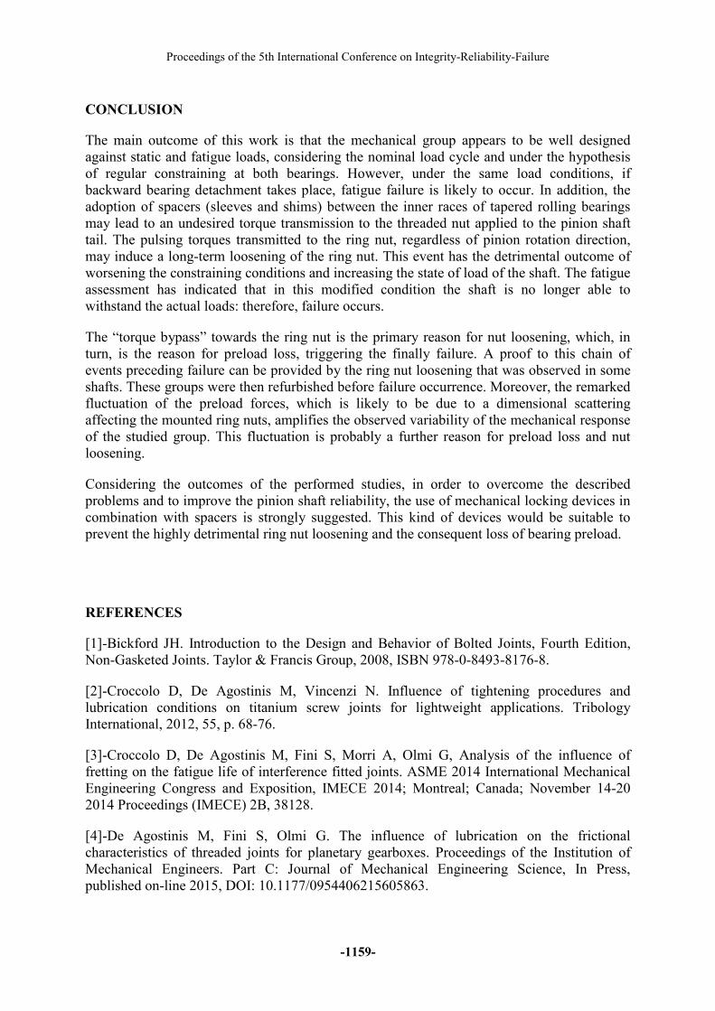
CONCLUSION
The main outcome of this work is that the mechanical group appears to be well designed
against static and fatigue loads, considering the nominal load cycle and under the hypothesis
of regular constraining at both bearings. However, under the same load conditions, if
backward bearing detachment takes place, fatigue failure is likely to occur. In addition, the
adoption of spacers (sleeves and shims) between the inner races of tapered rolling bearings
may lead to an undesired torque transmission to the threaded nut applied to the pinion shaft
tail. The pulsing torques transmitted to the ring nut, regardless of pinion rotation direction,
may induce a long-term loosening of the ring nut. This event has the detrimental outcome of
worsening the constraining conditions and increasing the state of load of the shaft. The fatigue
assessment has indicated that in this modified condition the shaft is no longer able to
withstand the actual loads: therefore, failure occurs.
The “torque bypass” towards the ring nut is the primary reason for nut loosening, which, in
turn, is the reason for preload loss, triggering the finally failure. A proof to this chain of
events preceding failure can be provided by the ring nut loosening that was observed in some
shafts. These groups were then refurbished before failure occurrence. Moreover, the remarked
fluctuation of the preload forces, which is likely to be due to a dimensional scattering
affecting the mounted ring nuts, amplifies the observed variability of the mechanical response
of the studied group. This fluctuation is probably a further reason for preload loss and nut
loosening.
Considering the outcomes of the performed studies, in order to overcome the described
problems and to improve the pinion shaft reliability, the use of mechanical locking devices in
combination with spacers is strongly suggested. This kind of devices would be suitable to
prevent the highly detrimental ring nut loosening and the consequent loss of bearing preload.
REFERENCES
[1]-Bickford JH. Introduction to the Design and Behavior of Bolted Joints, Fourth Edition,
Non-Gasketed Joints. Taylor & Francis Group, 2008, ISBN 978-0-8493-8176-8.
[2]-Croccolo D, De Agostinis M, Vincenzi N. Influence of tightening procedures and
lubrication conditions on titanium screw joints for lightweight applications. Tribology
International, 2012, 55, p. 68-76.
[3]-Croccolo D, De Agostinis M, Fini S, Morri A, Olmi G, Analysis of the influence of
fretting on the fatigue life of interference fitted joints. ASME 2014 International Mechanical
Engineering Congress and Exposition, IMECE 2014; Montreal; Canada; November 14-20
2014 Proceedings (IMECE) 2B, 38128.
[4]-De Agostinis M, Fini S, Olmi G. The influence of lubrication on the frictional
characteristics of threaded joints for planetary gearboxes. Proceedings of the Institution of
Mechanical Engineers. Part C: Journal of Mechanical Engineering Science, In Press,
published on-line 2015, DOI: 10.1177/0954406215605863.

Symposium_17: Mechanical Connections
-1160-
[5]-Filla R. Optimizing the trajectory of a wheel loader working in short loading cycles. The
13th Scandinavian International Conference on Fluid Power, SICFP2013, June 3-5, 2013,
Linköping, Sweden.
[6]-Niemann G, Winter H, Hohn BR. Maschinenelemente: Band 1: Konstruktion und
Berechnung von Verbindungen, Lagern, Wellen, Springer-Verlag: Berlin, Germany, 2005.
[7]-Niemann G, Winter H, Hohn BR. Maschinenelemente: Band 2: Getriebe allgemein,
Zahnradgetriebe - Grundlagen, Stirnradgetriebe, Springer-Verlag: Berlin, Germany, 2005.
[8]-Pilkey WD, Pilkey DF, Peterson RE. Peterson’s Stress Concentration Factors, 3rd Edition,
Wiley: New Jersey, United States, 2008.
[9]-Timken Engineering Manual. Available on-line at http://www.timken.com/en-
us/products/Documents/Timken-Engineering-Manual.pdf, 2011.