
Failure Analysis and Optimization of Universal Joint Yoke ... · PDF filestress analysis is...
7
International Research Journal of Engineering and Technology (IRJET) e-ISSN: 2395-0056 Volume: 02 Issue: 07 | Oct-2015 www.irjet.net p-ISSN: 2395-0072 © 2015, IRJET ISO 9001:2008 Certified Journal Page 229 FAILURE ANALYSIS AND OPTIMIZATION OF UNIVERSAL JOINT YOKE SUBJECTED BY TORSION AND SHEAR Avinash C Vasekar, Ranjitsinha R. Gidde, 1Research scholar, Department of Mechanical Engineering, SVERI’s College of Engineering, Gopalpur ,Pandharpur 2Department of Mechanical Engineering, SVERI’s College of Engineering, Gopalpur, Pandharpur ---------------------------------------------- -----------------------***--------------------------------------------------------------------- ABSTRACT Automobile transmission system consist several components which sometimes suffer from different stresses (failures). Yoke assembly are one of the most important part in propeller shaft. This Yoke assembly are always subjected by Torsion and Shear. Yoke assembly are rotating part & sometime suffer from fatigue by application of variable torque. In this study, failure analysis and weight optimization of a universal joint yoke of an automobile power transmission system are carried out. The universal joint consists of two forged-steel yokes flange & tube Yoke cross trunnion hold two Yoke together at right angles to each other. Key words: Yoke joint, Power transmission system, Analytical modelling, Optimization Torsion & Shear. I.INTRODUCTION Power transmission system of vehicles consist several components which sometimes encounter unfortunate failures. Some common reasons for the failures may be manufacturing and design faults, maintenance faults, raw material faults, material processing faults as well as the user originated faults. Spectroscopic analyses, metallographic analyses and hardness tests are done. For the determination of stress conditions at the failed section, stress analysis is also carried out by the finite element method. The common failure types in automobiles are the failures in the transmission system elements which cover 25% of all the automobile failures. In day-to-day life every aspect is influenced by the work of engineer. The equipments we use, the food we eat, and the vehicles we travel in and many more all are developed with the assistance of design engineering. Traditional design has been done by simple calculation. But with increase in product performance and reliability it is difficult to follow the traditional iterative design procedures. As product performance becomes more important and as designs becomes more complex the simple method have becomes inadequate. To understand the growth and its implication for design, it is necessary to look at how design solutions are implemented. To satisfy the market needs it is necessary to provide a computational capacity along with the creativity of the human being. By adding computer technology to the armory of the designer, the best qualities of the designer can be linked with the best qualities of the computer. Most engineering designs are too complex for traditional approach. For example a structure may have spatially dependent material properties if different materials are used; the geometry may be irregular in some sense or the boundary condition may be complex. In all these examples no solution functions exist and so solutions can be achieved only by resorting to an approximate numerical method. A widely used numerical method for solving structural problems in both industry and academia is “FINITE ELEMENT METHOD [1] studied power transmission system of vehicle consist several components which sometimes encounter unfortunate failures. The fracture analysis of a universal joint yoke and a drive shaft of an automobile power transmission system were carried out. Spectroscopic analyses, metallographic analyses and hardness measurements were carried out for each part. For the determination of stress conditions at the
Transcript of Failure Analysis and Optimization of Universal Joint Yoke ... · PDF filestress analysis is...

International Research Journal of Engineering and Technology (IRJET) e-ISSN: 2395-0056
Volume: 02 Issue: 07 | Oct-2015 www.irjet.net p-ISSN: 2395-0072
© 2015, IRJET ISO 9001:2008 Certified Journal Page 229
FAILURE ANALYSIS AND OPTIMIZATION OF UNIVERSAL JOINT YOKE SUBJECTED BY TORSION AND SHEAR
Avinash C Vasekar, Ranjitsinha R. Gidde,
1Research scholar, Department of Mechanical Engineering, SVERI’s College of Engineering, Gopalpur ,Pandharpur
2Department of Mechanical Engineering, SVERI’s College of Engineering, Gopalpur, Pandharpur
---------------------------------------------- -----------------------***---------------------------------------------------------------------ABSTRACT
Automobile transmission system consist several
components which sometimes suffer from different
stresses (failures). Yoke assembly are one of the most
important part in propeller shaft. This Yoke assembly are
always subjected by Torsion and Shear. Yoke assembly are
rotating part & sometime suffer from fatigue by
application of variable torque. In this study, failure
analysis and weight optimization of a universal joint yoke
of an automobile power transmission system are carried
out. The universal joint consists of two forged-steel yokes
flange & tube Yoke cross trunnion hold two Yoke together
at right angles to each other.
Key words: Yoke joint, Power transmission system,
Analytical modelling, Optimization Torsion & Shear.
I.INTRODUCTION
Power transmission system of vehicles consist several
components which sometimes encounter unfortunate
failures. Some common reasons for the failures may be
manufacturing and design faults, maintenance faults, raw
material faults, material processing faults as well as the
user originated faults. Spectroscopic analyses,
metallographic analyses and hardness tests are done. For
the determination of stress conditions at the failed section,
stress analysis is also carried out by the finite element
method. The common failure types in automobiles are the
failures in the transmission system elements which cover
25% of all the automobile failures.
In day-to-day life every aspect is influenced by the work of
engineer. The equipments we use, the food we eat, and the
vehicles we travel in and many more all are developed
with the assistance of design engineering. Traditional
design has been done by simple calculation. But with
increase in product performance and reliability it is
difficult to follow the traditional iterative design
procedures. As product performance becomes more
important and as designs becomes more complex the
simple method have becomes inadequate. To understand
the growth and its implication for design, it is necessary to
look at how design solutions are implemented. To satisfy
the market needs it is necessary to provide a
computational capacity along with the creativity of the
human being. By adding computer technology to the
armory of the designer, the best qualities of the designer
can be linked with the best qualities of the computer. Most
engineering designs are too complex for traditional
approach. For example a structure may have spatially
dependent material properties if different materials are
used; the geometry may be irregular in some sense or the
boundary condition may be complex. In all these examples
no solution functions exist and so solutions can be
achieved only by resorting to an approximate numerical
method. A widely used numerical method for solving
structural problems in both industry and academia is
“FINITE ELEMENT METHOD [1] studied power
transmission system of vehicle consist several
components which sometimes encounter unfortunate
failures. The fracture analysis of a universal joint yoke and
a drive shaft of an automobile power transmission system
were carried out. Spectroscopic analyses, metallographic
analyses and hardness measurements were carried out for
each part. For the determination of stress conditions at the
International Research Journal of Engineering and Technology (IRJET) e-ISSN: 2395-0056
Volume: 02 Issue: 07 | Oct-2015 www.irjet.net p-ISSN: 2395-0072
© 2015, IRJET ISO 9001:2008 Certified Journal Page 230
failed section, stress analysis was also carried out by the
finite element method. An experimental and finite-element
analysis of universal coupling was carried out with help of
ANSYS for different torque condition. [2] studied some
common reason for failure of drive shaft and universal
joint yoke of automobile power transmission system such
that failure may be manufacturing and design faults,
material processing fault and user originated faults. The
failure analysis was carried out for a universal joint yoke
and a drive shaft of an automobile power transmission
system. The investigation was carried out for
spectroscopic and metallographic analyses and hardness
measurement for determination of stress condition at the
failure section. investigated about effect of an optimal
magnetic yoke configuration maximizing the magnitude
flux density and improving flux uniformly in the strips,
which will increase the transducer signal output. Topology
optimization method was employed to find optimal yoke
configuration in this investigation. The series of
experiments was performed on an aluminum plate, that
experiments were conducted using a grating with and
without the designated yoke, when the yoke was used; the
signal outputs increased up to 60%. [4] investigated about
failure reason of yoke connectors of over head power lines
these components were produced by bending steel plate
and their subsequent hot dip galvanizing. The performed
investigation included metallographic analyses, semi-
quantitive chemical microanalyses, micro-hardness,
measurements and numerical simulation also observed
that failure occured due to several degradation process
related to liquid metal assisted cracking which occurred
during bending. [5] carried out model analysis of drive
shaft using FEA, the inherent frequencies and vibration
mode shapes with their respective deformation.In this
work finite element analysis of a drive shaft had been
taken as a case study. The maximum stress point and
dangerous areas were found by the deformation analysis
of drive shaft. The relationship between the frequency and
the vibration modal was explained by the modal analysis
of drive shaft.The deformation and stress contours were
plotted and patterns were studied. The results were
compared and verified with available existing results. The
optimization of drive shaft also achieves the reduction in
the weight of the assembly of universal joint and thus
reduction in cost. [6]carried out metallurgical evaluation
of aluminum alloy yoke from an aerial platform device and
performed chemical and mechanic testing of yoke tube.
Studied on design issues associated with fatigue cracking,
photo documentation, metallurgical replication etc. and
chemical analysis, tensile testing and scanning electron
microscopy was done. A metallurgical inspection and
evaluation was performed on an aerial platform yoke from
a fire-fighting vehicle chassis that had been removed from
service
II. SIMULATION
1. Finite element analysis of Universal joint yoke
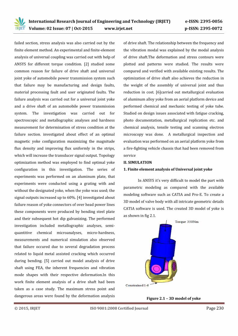
In ANSYS it’s very difficult to model the part with
parametric modeling as compared with the available
modeling software such as CATIA and Pro-E. To create a
3D model of valve body with all intricate geometric details
CATIA software is used. The created 3D model of yoke is
as shown in fig 2.1.
Figure 2.1 – 3D model of yoke

International Research Journal of Engineering and Technology (IRJET) e-ISSN: 2395-0056
Volume: 02 Issue: 07 | Oct-2015 www.irjet.net p-ISSN: 2395-0072
© 2015, IRJET ISO 9001:2008 Certified Journal Page 231
While creating 3D model care has been taken to
model it with parametric expression, so as the dimensions
changes it will reduce the repetitive time required for
modeling. Small steps and champers are eliminated while
modeling. The created 3D model is saved in part.igs file
format, as this file format is suitable during importing this
model for meshing in Hypermesh software. Meshing of the
3D yoke model
In simple term meshing means connecting
elements with each other. Elements are the building
blocks of the finite element analysis. Meshing is carried
out by using Hypermesh software as Hypermesh is
dedicated software largely used for meshing.
Meshing is an important step in FEA analysis. The meshing
is adequately done to obtain the accurate results while
computations. Model is meshed by using SOLID 45
element and with 7 element size. Total 84213 elements
and 116154 nodes were created after meshing.
When more the number of elements taken, better accuracy
is obtained but simultaneously the computational time
increases tremendously.
Figure 2.2 - Meshed model
Fig.2.3 Displacement contour
Fig.2.4 Stress contour
No of elements 84,213
No of Nodes 1,16,154
Element C3D10 second order tetra element
Pre Processing Hypremesh 12
Solver Abaqus
Post Processing Hyper view
Analysis Implicit analysis
Material M3A452_A23_MS

International Research Journal of Engineering and Technology (IRJET) e-ISSN: 2395-0056
Volume: 02 Issue: 07 | Oct-2015 www.irjet.net p-ISSN: 2395-0072
© 2015, IRJET ISO 9001:2008 Certified Journal Page 232
Max Stress is 284 MPa
Figure 2.5 Stress Contour
Figure 2.6 Stress Contour
Transmission Yoke is analysed under 350Nm
Torque load. Max stress observed 284 MPa (yield
170 MPa).
Stresses observed in Yoke are more than yield
limit.
2. Further scope of work-
Weight optimization Strategy Adopted – Topology
Optimization
The aim of topology optimization of transmission Yoke is
to find the best use of material for a body to given
constraints (deflection, volume or mass reduction).
Generally, topology optimization is carried out before
shape or size optimizations. Preliminary stage of any static
analysis is to decide the loading and boundary conditions;
the experimental testing was carried out to determine the
stresses acting on yoke assembly for modified part.
Topology optimization is, in addition, concerned with the
number of connected components/boundaries belonging
to the domain. Such methods are needed since typically
shape optimization methods work in a subset of allowable
shapes which have fixed topological properties, such as
having a fixed number of holes in yoke. Topological
optimization techniques can then help work around the
limitations of pure shape optimization.
Objective – To reduce stress levels below yield limit.
Response – volume fraction and stresses
Constraint – Stress limit,30% volume of current volume.

International Research Journal of Engineering and Technology (IRJET) e-ISSN: 2395-0056
Volume: 02 Issue: 07 | Oct-2015 www.irjet.net p-ISSN: 2395-0072
© 2015, IRJET ISO 9001:2008 Certified Journal Page 233
Figure 2.7 Element density distribution
Figure 2.8 Element density distribution
Gray color region describes dead zone or elements from
same region are not contribute to external load. There is a
scope of removing material from same region.
Figure 2.9 Modified geometry
Modified geometry imposed over baseline geometry.
Fillets are provided in order to reduce stress
concentration.
Figure 2.10 Modified geometry
Modified geometry imposed over baseline geometry.
Geometry modified in order to reduce stress level with
reducing stress levels. Stiffness increase in critical zone.
Figure 2.11 Modified geometry- element distribution
Max deflection 1.8 mm
Baseline Geometry
Modified Geometry
International Research Journal of Engineering and Technology (IRJET) e-ISSN: 2395-0056
Volume: 02 Issue: 07 | Oct-2015 www.irjet.net p-ISSN: 2395-0072
© 2015, IRJET ISO 9001:2008 Certified Journal Page 234
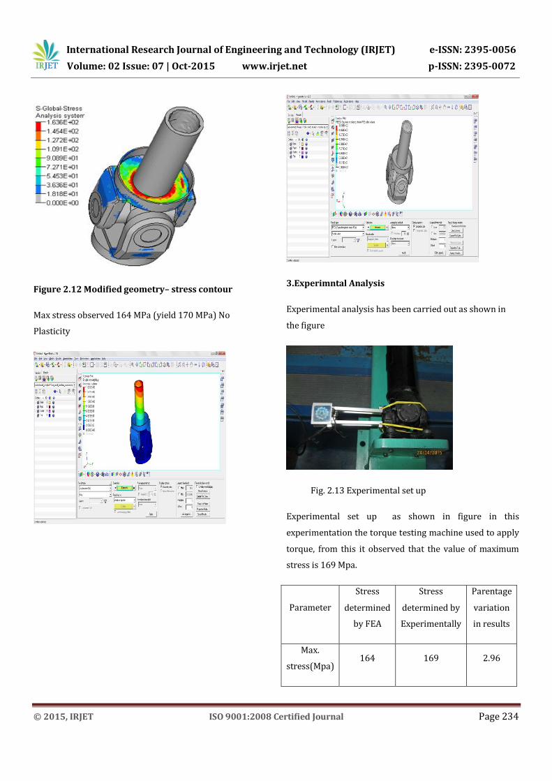
Figure 2.12 Modified geometry– stress contour
Max stress observed 164 MPa (yield 170 MPa) No
Plasticity
3.Experimntal Analysis
Experimental analysis has been carried out as shown in
the figure
Fig. 2.13 Experimental set up
Experimental set up as shown in figure in this
experimentation the torque testing machine used to apply
torque, from this it observed that the value of maximum
stress is 169 Mpa.
Parameter
Stress
determined
by FEA
Stress
determined by
Experimentally
Parentage
variation
in results
Max.
stress(Mpa) 164 169 2.96

International Research Journal of Engineering and Technology (IRJET) e-ISSN: 2395-0056
Volume: 02 Issue: 07 | Oct-2015 www.irjet.net p-ISSN: 2395-0072
© 2015, IRJET ISO 9001:2008 Certified Journal Page 235
III.RESULT AND DISCUSSION
In this paper weight optimization has been carried out
with help of hyper mesh. Firstly the weight of universal
joint was 1.11 kg on which analysis carried out from
169MPa value of maximum stress is obtained. After
modification or weight optimization the weight of joint get
reduced to 0.967kg that 12.8% reduction in weight .the
optimization is carried out in hyper mesh in that the value
of maximum stress is 169 Mpa. Experimental analysis has
been carried out which is compared hyper mesh to get
optimal design or exact value of maximum stress
Table no. 3.1 Weight of universal joint without
reducing weight Vs Weight of universal joint after
optimization weight
Weight of universal
joint without reducing
weight
Weight of universal
joint after optimization
weight
1110gm 967gm
As shown in above table the value optimized. From this
optimization the weight reduction is 12.8 %
Table no. 3.2 stress value without optimization Vs
stress value with optimization
Stress without
optimization(N/mm2)
Stress with
optimization(N/mm2)
170 164
From the analysis the resultant stress value obtained
IV.CONCLUSION
No plasticity observed after modification.
Weight optimization study carried out in Optistruct.
This study helps to reduce weight of yoke by 12.8 %
over original component.
Weight of base geometry is 1.11 kg while modified
geometry is 967 gm
V. REFERENCES
1. Siraj Mohammad Ali Sheikh, “Analysis Of Universal
Coupling Under Different Torque Condition”,
International Journal of Engineering Science &
Advanced technology,May-June 2012, Volume-2,
Issue-3, 690 – 694.
2. H Bayrakceken, S. Tasgetiren, I. Yavuz, “Two cases of
failure in the power transmission systemon vehicles:
A universal joint yoke and a drive shaft”, Engineering
Failure Analysis14 (2007)pp.716-724.
3. IkKyu Kim,Woochul Kim, Yoon Young Kim,
“Magnetostrictive grating with an optimal yoke for
generatinghigh-output frequency-tuned SH waves in a
plate” , Sensors and Actuators A137(2007)pp.141-
146.
4. Miroslav Dzupon, LadislavFalat, Jan Slota,
PavolHvizdos, “Failure analysis of overhead power
line yoke connector”, Engineering Failure
Analysis33(2013)pp.66-74.
5. Ravikant, GopalKrishan, MukeshDidwania“Modal
analysis of drive shaft using FEA”,International
journal of engineering and Management Research,
Vol-3, Issue-1, Feb 2013 pp.4-7.
6. Timothy R. Smith, “An evaluation of fatigue cracking in
an aerial platform yoke from a five-fighting vehicle”,
Engineering Failure Analysis 9,March-2003,Page 303-
312.


![Finite Element Analysis[May2014]](https://static.fdocuments.us/doc/165x107/55cf921c550346f57b93a5d9/finite-element-analysismay2014-5612ce55d2a43.jpg)

