FAI Sporting Code - Fédération Aéronautique … Sporting Code Section 4 – Aeromodelling Volume...
114
FAI Sporting Code Section 4 – Aeromodelling Volume F2 Control Line Model Aircraft 2018 Edition Effective 1st January 2018 F2A – CL SPEED F2B – CL AEROBATICS F2C – CL TEAM RACING F2D – CL COMBAT ANNEX 4A - CLASS F2A - SPEED JUDGES' GUIDE ANNEX 4B - CLASS F2B - AEROBATICS JUDGES' GUIDE ANNEX 4C - CLASS F2C - TEAM RACE JUDGES' GUIDE ANNEX 4D - CLASS F2D - COMBAT JUDGES’ GUIDE ANNEX 4E - CONTROL LINE WORLD CUP RULES ANNEX 4F - CONTROL LINE ORGANISERS' GUIDE ANNEX 4G - CLASS F2E – CL DIESEL MOTOR COMBAT (PROVISIONAL CLASS) ANNEX 4H - CLASS F2F – CL DIESEL PROFILE TEAM RACING (PROVISIONAL CLASS) ANNEX 4J - CLASS F2B MANOEUVRE DIAGRAMS (REFER TO THE SEPARATE DOCUMENT ENTITLED "VOLUME F2, CONTROL LINE MODEL AIRCRAFT, ANNEX 4J") ANNEX 4K - CLASS F2G – CL ELECTRIC SPEED (PROVISIONAL CLASS) ANNEX 4L - F2C NOISE REDUCTION PLAN Maison du Sport International Avenue de Rhodanie 54 CH-1007 Lausanne Switzerland Tel: +41(0)21/345.10.70 Fax: +41(0)21/345.10.77 Email: [email protected] Web: www.fai.org
Transcript of FAI Sporting Code - Fédération Aéronautique … Sporting Code Section 4 – Aeromodelling Volume...

FAI Sporting Code
Section 4 – Aeromodelling
Volume F2
Control Line Model Aircraft
2018 Edition Effective 1st January 2018
F2A – CL SPEED
F2B – CL AEROBATICS
F2C – CL TEAM RACING
F2D – CL COMBAT
ANNEX 4A - CLASS F2A - SPEED JUDGES' GUIDE
ANNEX 4B - CLASS F2B - AEROBATICS JUDGES' GUIDE
ANNEX 4C - CLASS F2C - TEAM RACE JUDGES' GUIDE
ANNEX 4D - CLASS F2D - COMBAT JUDGES’ GUIDE
ANNEX 4E - CONTROL LINE WORLD CUP RULES
ANNEX 4F - CONTROL LINE ORGANISERS' GUIDE
ANNEX 4G - CLASS F2E – CL DIESEL MOTOR COMBAT (PROVISIONAL CLASS)
ANNEX 4H - CLASS F2F – CL DIESEL PROFILE TEAM RACING (PROVISIONAL CLASS)
ANNEX 4J - CLASS F2B MANOEUVRE DIAGRAMS (REFER TO THE SEPARATE DOCUMENT ENTITLED "VOLUME F2, CONTROL LINE MODEL AIRCRAFT, ANNEX 4J")
ANNEX 4K - CLASS F2G – CL ELECTRIC SPEED (PROVISIONAL CLASS)
ANNEX 4L - F2C NOISE REDUCTION PLAN
Maison du Sport International Avenue de Rhodanie 54
CH-1007 Lausanne Switzerland
Tel: +41(0)21/345.10.70 Fax: +41(0)21/345.10.77
Email: [email protected] Web: www.fai.org
FEDERATION AERONAUTIQUE INTERNATIONALE
MSI - Avenue de Rhodanie 54 – CH-1007 Lausanne – Switzerland
Copyright 2018 All rights reserved. Copyright in this document is owned by the Fédération Aéronautique Internationale (FAI). Any person acting on behalf of the FAI or one of its Members is hereby authorised to copy, print, and distribute this document, subject to the following conditions: 1. The document may be used for information only and may not be exploited for commercial
purposes. 2. Any copy of this document or portion thereof must include this copyright notice. 3. Regulations applicable to air law, air traffic and control in the respective countries are reserved
in any event. They must be observed and, where applicable, take precedence over any sport regulations.
Note that any product, process or technology described in the document may be the subject of other Intellectual Property rights reserved by the Fédération Aéronautique Internationale or other entities and is not licensed hereunder.
RIGHTS TO FAI INTERNATIONAL SPORTING EVENTS
All international sporting events organised wholly or partly under the rules of the Fédération Aéronautique
Internationale (FAI) Sporting Code1 are termed FAI International Sporting Events2. Under the FAI Statutes3,
FAI owns and controls all rights relating to FAI International Sporting Events. FAI Members4 shall, within their
national territories5, enforce FAI ownership of FAI International Sporting Events and require them to be
registered in the FAI Sporting Calendar6.
An event organiser who wishes to exploit rights to any commercial activity at such events shall seek prior agreement with FAI. The rights owned by FAI which may, by agreement, be transferred to event organisers include, but are not limited to advertising at or for FAI events, use of the event name or logo for merchandising purposes and use of any sound, image, program and/or data, whether recorded electronically or otherwise or transmitted in real time. This includes specifically all rights to the use of any material, electronic or other, including software, that forms part of any method or system for judging, scoring, performance evaluation or
information utilised in any FAI International Sporting Event7.
Each FAI Air Sport Commission8 may negotiate agreements, with FAI Members or other entities authorised by the appropriate FAI Member, for the transfer of all or parts of the rights to any FAI International Sporting Event
(except World Air Games events9) in the discipline10, for which it is responsible11 or waive the rights. Any such agreement or waiver, after approval by the appropriate Air Sport Commission President, shall be signed
by FAI Officers12.
Any person or legal entity that accepts responsibility for organising an FAI Sporting Event, whether or not by written agreement, in doing so also accepts the proprietary rights of FAI as stated above. Where no transfer of rights has been agreed in writing, FAI shall retain all rights to the event. Regardless of any agreement or transfer of rights, FAI shall have, free of charge for its own archival and/or promotional use, full access to any sound and/or visual images of any FAI Sporting Event. The FAI also reserves the right to arrange at its own expense for any and all parts of any event to be recorded.
1 FAI Statutes, Chapter 1, para. 1.6
2 FAI Sporting Code, Gen. Section, Chapter 4, .. para 4.1.2
3 FAI Statutes, Chapter 1, para 1.8.1
4 FAI Statutes, Chapter 2, para 2.1.1; 2.4.2; 2.5.2 and 2.7.2
5 FAI By-Laws, Chapter 1, para 1.2.1
6 FAI Statutes, Chapter 2, para 2.4.2.2.5
7 FAI By-Laws, Chapter 1, paras 1.2.2 to 1.2.5
8 FAI Statutes, Chapter 5, paras 5.1.1, 5.2, 5.2.3 and 5.2.3.3
9 FAI Sporting Code, Gen. Section, Chapter 4, ... para 4.1.5
10 FAI Sporting Code, Gen. Section, Chapter 2, ... para 2.2.
11 FAI Statutes, Chapter 5, para 5.2.3.3.7
12 FAI Statutes, Chapter 6, para 6.1.2.1.3

SC4_Vol_F2_ControlLine_18 Effective 1st January 2018 Page 4
PAGE DELIBERATELY LEFT BLANK

SC4_Vol_F2_ControlLine_18 Effective 1st January 2018 Page 5
VOLUME F2
SECTION 4C – MODEL AIRCRAFT – F2 – CONTROL LINE
PART FOUR – TECHNICAL REGULATIONS FOR CONTROL LINE CONTESTS
4.1 Class F2A – CL Speed
4.2 Class F2B – CL Aerobatics
4.3 Class F2C – CL Team Racing
4.4 Class F2D – CL Combat
Annex 4A - Class F2A Judges’ Guide
Annex 4B - Class F2B Judges’ Guide
Annex 4C - Class F2C Team Race Judges Guide
Annex 4D - Class F2D Judges’ Guide
Annex 4E - Control Line World Cup Rules
Annex 4F - Control Line Organisers’ Guide
Annex 4G - Class F2E CL Diesel Motor Combat (provisional class)
Annex 4H - Class F2F CL Diesel Profile Team Racing (provisional class)
Annex 4J - Class F2B Manoeuvre Diagrams *
Annex 4K - Class F2G CL Electric Speed (provisional class)
Annex 4L - Class F2C Noise Reduction Plan
* Note: Annex 4J is in a separate document entitled “Volume F2, Control Line, Annex 4J”.
Note: Designation upper-case “I” is not used to avoid confusion with lower-case character “l” and the digit “1”.
SC4_Vol_F2_ControlLine_18 Effective 1st January 2018 Page 6
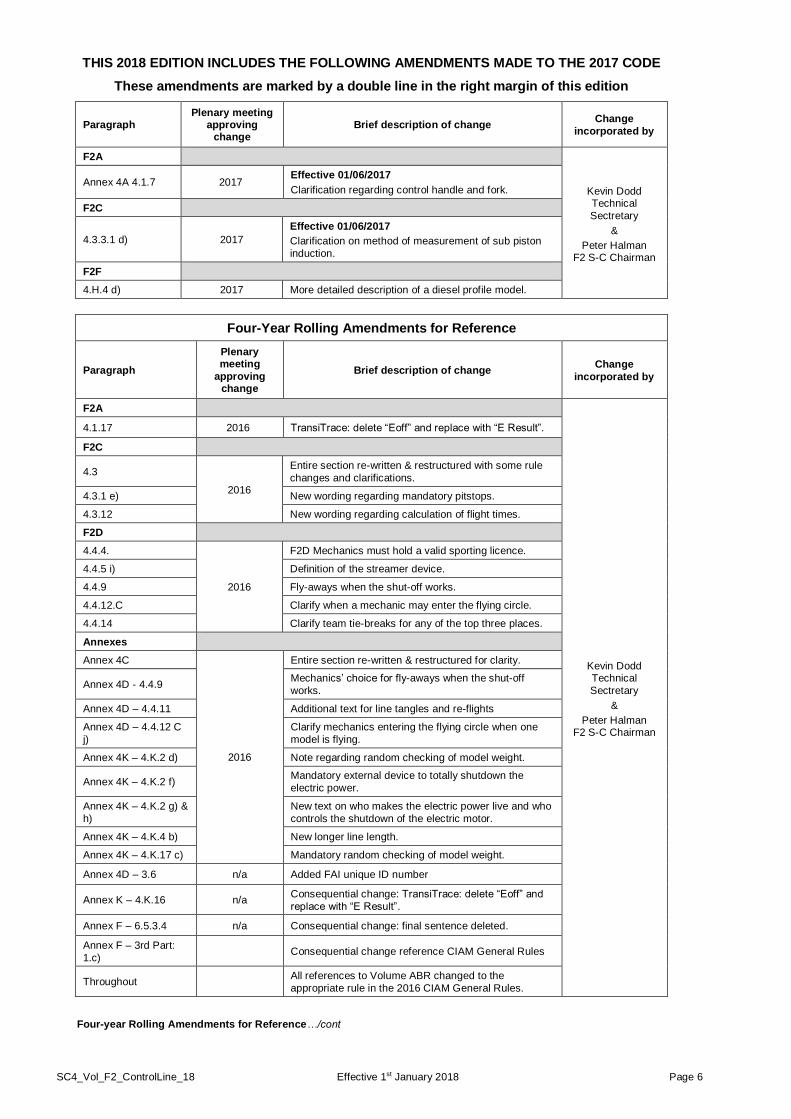
THIS 2018 EDITION INCLUDES THE FOLLOWING AMENDMENTS MADE TO THE 2017 CODE
These amendments are marked by a double line in the right margin of this edition
Paragraph Plenary meeting
approving change
Brief description of change Change
incorporated by
F2A
Kevin Dodd Technical
Sectretary
&
Peter Halman F2 S-C Chairman
Annex 4A 4.1.7 2017 Effective 01/06/2017
Clarification regarding control handle and fork.
F2C
4.3.3.1 d) 2017
Effective 01/06/2017
Clarification on method of measurement of sub piston
induction.
F2F
4.H.4 d) 2017 More detailed description of a diesel profile model.
Four-Year Rolling Amendments for Reference
Paragraph
Plenary meeting
approving change
Brief description of change Change
incorporated by
F2A
Kevin Dodd Technical
Sectretary
&
Peter Halman F2 S-C Chairman
4.1.17 2016 TransiTrace: delete “Eoff” and replace with “E Result”.
F2C
4.3
2016
Entire section re-written & restructured with some rule
changes and clarifications.
4.3.1 e) New wording regarding mandatory pitstops.
4.3.12 New wording regarding calculation of flight times.
F2D
4.4.4.
2016
F2D Mechanics must hold a valid sporting licence.
4.4.5 i) Definition of the streamer device.
4.4.9 Fly-aways when the shut-off works.
4.4.12.C Clarify when a mechanic may enter the flying circle.
4.4.14 Clarify team tie-breaks for any of the top three places.
Annexes
Annex 4C
2016
Entire section re-written & restructured for clarity.
Annex 4D - 4.4.9 Mechanics’ choice for fly-aways when the shut-off
works.
Annex 4D – 4.4.11 Additional text for line tangles and re-flights
Annex 4D – 4.4.12 C
j)
Clarify mechanics entering the flying circle when one
model is flying.
Annex 4K – 4.K.2 d) Note regarding random checking of model weight.
Annex 4K – 4.K.2 f) Mandatory external device to totally shutdown the
electric power.
Annex 4K – 4.K.2 g) &
h)
New text on who makes the electric power live and who
controls the shutdown of the electric motor.
Annex 4K – 4.K.4 b) New longer line length.
Annex 4K – 4.K.17 c) Mandatory random checking of model weight.
Annex 4D – 3.6 n/a Added FAI unique ID number
Annex K – 4.K.16 n/a Consequential change: TransiTrace: delete “Eoff” and
replace with “E Result”.
Annex F – 6.5.3.4 n/a Consequential change: final sentence deleted.
Annex F – 3rd Part:
1.c) Consequential change reference CIAM General Rules
Throughout All references to Volume ABR changed to the
appropriate rule in the 2016 CIAM General Rules.
Four-year Rolling Amendments for Reference…/cont
SC4_Vol_F2_ControlLine_18 Effective 1st January 2018 Page 7
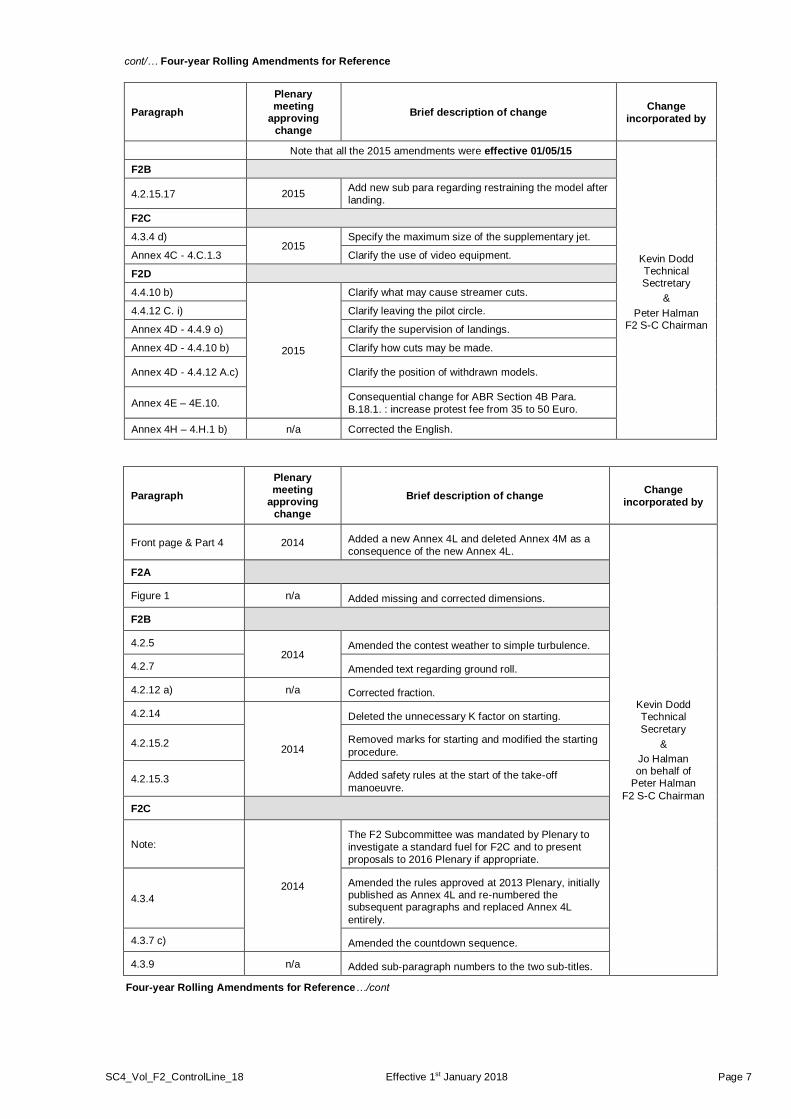
cont/… Four-year Rolling Amendments for Reference
Paragraph
Plenary meeting
approving change
Brief description of change Change
incorporated by
Note that all the 2015 amendments were effective 01/05/15
Kevin Dodd Technical Sectretary
&
Peter Halman F2 S-C Chairman
F2B
4.2.15.17 2015 Add new sub para regarding restraining the model after
landing.
F2C
4.3.4 d) 2015
Specify the maximum size of the supplementary jet.
Annex 4C - 4.C.1.3 Clarify the use of video equipment.
F2D
4.4.10 b)
2015
Clarify what may cause streamer cuts.
4.4.12 C. i) Clarify leaving the pilot circle.
Annex 4D - 4.4.9 o) Clarify the supervision of landings.
Annex 4D - 4.4.10 b) Clarify how cuts may be made.
Annex 4D - 4.4.12 A.c) Clarify the position of withdrawn models.
Annex 4E – 4E.10. Consequential change for ABR Section 4B Para.
B.18.1. : increase protest fee from 35 to 50 Euro.
Annex 4H – 4.H.1 b) n/a Corrected the English.
Paragraph
Plenary meeting
approving change
Brief description of change Change
incorporated by
Front page & Part 4 2014 Added a new Annex 4L and deleted Annex 4M as a
consequence of the new Annex 4L.
Kevin Dodd Technical
Secretary
&
Jo Halman on behalf of
Peter Halman
F2 S-C Chairman
F2A
Figure 1 n/a Added missing and corrected dimensions.
F2B
4.2.5 2014
Amended the contest weather to simple turbulence.
4.2.7 Amended text regarding ground roll.
4.2.12 a) n/a Corrected fraction.
4.2.14
2014
Deleted the unnecessary K factor on starting.
4.2.15.2 Removed marks for starting and modified the starting
procedure.
4.2.15.3 Added safety rules at the start of the take-off
manoeuvre.
F2C
Note:
2014
The F2 Subcommittee was mandated by Plenary to
investigate a standard fuel for F2C and to present
proposals to 2016 Plenary if appropriate.
4.3.4
Amended the rules approved at 2013 Plenary, initially published as Annex 4L and re-numbered the subsequent paragraphs and replaced Annex 4L
entirely.
4.3.7 c) Amended the countdown sequence.
4.3.9 n/a Added sub-paragraph numbers to the two sub-titles.
Four-year Rolling Amendments for Reference…/cont

SC4_Vol_F2_ControlLine_18 Effective 1st January 2018 Page 8
cont/… Four-year Rolling Amendments for Reference
Annexes
Annex 4A n/a
Changed sub-paragraph numbers to bullet points for clarity and amended the points as consequential changes from Plenary 2012 that were not applied at
the time.
Annex 4D, Rule 4.4.5
2014
Added sub-para h) regarding cutting streamers.
Annex 4F, Item 3 All F2D rounds to be eliminating rounds.
Annex 4K, 4.K.2 Deleted (i) the need for wheels and (ii) the time limit
and added sub-paragraph g) permitting a radio
control system for controlling the electric motor.
Annex 4K, 4.K.4 Shorten the flight radius and increase the laps.
Annex 4L Fully replace Annex and cross refer to rule change
4.3.4
Annex 4M Deleted as a consequence of the new Annex 4L.
Corrections not shown by double bars
Class F2B n/a
Deleted erroneous strike-through text.
Annex 4B Amended “he/she” to “he” throughout.
F2C 4.3.7 Corrected sub-paragraph numbering
F2C & Annex 4C Inserted “Figure” as appropriate throughout.
Paragraph
Plenary meeting approving
change Brief description of change
Change incorporated by
4.2.2.e) & f)
2013
F2B Amendments regarding pilot activated power shutdown. Jo Halman
Technical Secretary
Annex 4L F2C rule 4.3.4 effective 2015.
Annex 4M F2C Silencer testing procedure effective 2015.
RULE FREEZE FOR THIS VOLUME
With reference to paragraph A.10.2 of CIAM General Rules:
In all classes, the two-year rule for no changes to model aircraft/space model specifications, manoeuvre schedules and competition rules will be strictly enforced. For Championship classes, changes may be proposed in the year of the World Championship of each category.
For official classes without Championship status, the two-year cycle begins in the year that the Plenary Meeting approved the official status of the class. For official classes, changes may be proposed in the second year of the two-year cycle.
This means that in Volume F2:
a) changes can next be agreed at the Plenary Meeting of 2018 for application from 1st January 2019;
b) provisional classes are not subject to this restriction;
c) the F2B manoeuvre diagrams in Annex H, continue to be in a separate document called “Volume F2 Control Line Annex 4J”.
The only exceptions allowed to the two-year rule freeze are genuine and urgent safety matters, indispensable rule clarifications and noise rulings.

Class F2A – CL Speed
SC4_Vol_F2_ControlLine_18 Effective 1st January 2018 Page 9
VOLUME F2
SECTION FOUR - TECHNICAL REGULATIONS FOR CONTROL LINE CONTESTS
4.0 GENERAL F2 RULES
4.0.1 The contest organiser must provide a protective 2.5 m high wire enclosure at C/L speed and T/R contests to ensure the safety of spectators. For temporary circles, the height shall be at least 2.0 m high. The circuit surface shall be firm, smooth and free of grit or dust. The radius of all circles shall be clearly marked with a white line at least 25 mm wide. Provision of adequate practice areas shall be made before and during World and Continental Championships.
4.0.2 INTERRUPTION OF THE CONTEST
Wind stronger than 9 m/s for at least 30 seconds (instead of 12 m/s for at least one minute in CIAM General Rules).
4.0.3 Safety Strap
In accordance with CIAM General Rules B.1.2.2.e), for all F2 classes a safety strap connecting the competitor’s wrist to the control handle must be provided by the competitor and used during all flights A pull test shall be applied separately to the safety strap. This pull test will be applied according to each class specification concerning the lines’ pull test.
4.1. CLASS F2A – CL SPEED
Note: The F2A Judges' Guide is at Annex 4A.
4.1.1. Definition of a Speed Model Aircraft
Model aircraft in which the power is provided by a piston motor and in which lift is obtained by aerodynamic forces acting on the supporting surfaces, which remain fixed in flight except for control surfaces.
4.1.2 Characteristics of a Speed Model Aircraft
Maximum swept volume of motor or motors ..... 2.5 cm3
Minimum total projected area ............................ 5.0 dm2
Maximum total projected area ........................... 6.0 dm2
Maximum loading ............................................. 100 g/dm2
Maximum wingspan ......................................... 100 cm
To determine the wingspan of asymmetric model aircraft the thrust line of the model aircraft is used. Refer CIAM General Rules B.4.27
The model aircraft must take off from the ground.
A silencer is compulsory. Minimum internal volume 50 cm3. Maximum tailpipe internal diameter 6 mm.
An effective shutoff is compulsory so that the duration of high level noise can be limited to 20-30 seconds per flight.
4.1.3. Fuel
Fuel to a standard formula for glow plug and spark ignition motors will be supplied by the organisers. Its composition shall be 80% methanol, 20% first pressing castor oil. Fuel shall be mixed by volume.
Note: Fuel for compression ignition motors is not restricted.
Before each attempt for an official flight the fuel tank must be rinsed (washed out) with standard formula fuel.
4.1.4. Control Lines
a) Only two-line control is allowed, minimum control line diameter is 0.40 mm with a tolerance of minus 0.011 mm.
b) No intentional twisting and/or linking of the two lines together shall be permitted from the point of exit of the model aircraft to the control handle. The lines shall be separated by at least 5 mm at the point of exit from the model aircraft and at least 25 mm at the handle.
c) The lines must be round in cross-section and may not have any liquid or coating material applied. Solvent may be applied for cleaning only.

Class F2A – CL Speed
SC4_Vol_F2_ControlLine_18 Effective 1st January 2018 Page 10
4.1.5. Length of Course and Flight Circle.
a) The measured distance covered by the model aircraft must be at least one kilometre. The radius of the flight circle must be 17,69 m. (9 laps = 1 km).
b) A pilot’s circle 3 metres in radius and a safety circle 21 metres in radius shall be clearly marked on the ground. See Appendix III Annex 4F F2A Circle dimensions.
4.1.6. Line Tests (to be made before each attempt for an official flight)
The radius is measured from the axis of the pivot on the pylon, to the axis of the propeller. Where two propellers are employed, the axis of symmetry is taken as the reference for measurement.
A load sufficient only to remove the slack from the lines shall be applied during the line length check.
A load test shall be applied to the assembled control handle, lines and model aircraft equal to 50 times the weight of the model aircraft and this test shall be applied separately to the safety strap.
In each case the pull shall be applied three (3) times, slowly increasing to maximum load and releasing rapidly. The pull test should be made on the handle grip, not near the point of attachment of the lines (see sketch).
The diameter of the lines shall be checked at random distances on at least three points along the length of each line.
4.1.7. Control Handle and Pylon Fork
A pylon with supports, as shown in F2A Figure 1 will be placed at the disposal of the competitors by the organisers. It is compulsory that a pylon fork and control handle of standard dimensions as specified, be employed. The distance between the flexible point of attachment on the control handle and the point of contact of the horizontal bar on the fork shall be a maximum of 6 mm which is equal to half the diameter of the U-shaped bracket material. The horizontal bar (handle pivot) must be in continuous contact with the pylon fork during the official flights. (See the notes in the F2A Judges Guide.)
The pylon fork shall be infinitely adjustable between 1000 mm and 1600 mm from the ground and be steadily fixed to the ground surface. Mandatory dimensions are shown in the sketch. The pylon fork in its highest position may not deflect more than 20 mm when it is subjected to a horizontal pull test of 250 N.
A safety strap connecting the competitor's wrist to the control handle must be provided by the competitor and used during all flights.
Note: F2A Figure 1 appears overleaf.

Class F2A – CL Speed
SC4_Vol_F2_ControlLine_18 Effective 1st January 2018 Page 11
F2A Figure 1
Class F2A – CL Speed
SC4_Vol_F2_ControlLine_18 Effective 1st January 2018 Page 12
4.1.8. Definition of an Attempt
It is considered an attempt when the pilot does not engage the control handle in the pylon fork within 3 minutes after the starting signal.
4.1.9. Number of Attempts
In the case of an unsuccessful first attempt for an official flight, the competitor is entitled to a second attempt.
4.1.10 Definition of an Official Flight
The flight is official when timing commences.
4.1.11. Number of Flights
Each competitor is entitled to a minimum of three and a maximum of four official flights. The number of rounds shall be specified before the start of the competition. For the draw procedure, refer to F2A Judges Guide at Annex 4A, rule 4.1.9 Draw for Flying Order.
4.1.12. Number of Helpers
a) A pilot may not receive telecommunicated information during an attempt/flight.
b) Two helpers may assist the pilot in the contest circle.
c) In the case of a complete national Speed team (3 or 4 members), the two helpers must be two of the other team members or one team member and the team manager.
d) In the case of an incomplete national Speed team, supporters or members of other incomplete national Speed teams may act as helpers provided that they are registered as such to no more than one national team for the duration of the contest.
e) In the case where there are two entrants in an incomplete team, the second team member must act as one of the helpers for the other entrant from his own country. In this case, the entrants from the incomplete team may employ only one registered entrant from another incomplete team or one registered supporter from any country or the entrant’s team manager as their second helper.
f) In the case where there is a single entrant from a country the competitor may use two registered helpers. In this case the entrant from the incomplete team may employ up to two registered entrants from other incomplete teams or up to two registered supporters from any countries. Or the entrant’s team manager and one other helper as specified above.
g) In any case, the team manager may also enter the contest circle.
h) The defending champion, flying as an individual, may choose any helpers he wishes.
Note 1:- A maximum of four people may enter the circle, the pilot plus two helpers and the team manager; the fourth person may only act as an observer.
Note 2:- All references to “team” mean “Speed Team”
4.1.13. Starting of Timing
The timing commences officially when the competitor has placed his handle in the pylon fork and the model aircraft having made 2 complete circuits again passes the electronic sensor or the height marker on the edge of the circuit directly opposite the timekeepers.
4.1.14. Height of Flight
During the timing of an official flight, the flying height must not be less than one metre and not more than 3 metres.
4.1.15. Cancellation of the Flight
A flight is cancelled when:
a) any physical effort for the purpose of increasing the speed of the model aircraft during an official flight is applied by the pilot.
b) if at any time during the speed course the model aircraft exceeds a height of 6 metres or sustains a height in excess of 3 metres or less than one metre for more than one lap.
c) continuous contact is not maintained with the pylon fork during the official flight.
d) jettisoning occurs during the official flight.
cont/…

Class F2A – CL Speed
SC4_Vol_F2_ControlLine_18 Effective 1st January 2018 Page 13
4.1.16 Number of Timekeepers and Judges
a) The time shall be taken by either three timing officials equipped with 1/100-second resolution digital stopwatches or by an optical electronic system with equal or better resolution or accuracy.
b) For World and Continental Championships: where timekeeping is electronic, two electronic systems must be used. One system shall be designated the primary system and the speeds from this system shall be used for classification purposes. The other system shall be designated the secondary system and shall be the required back-up system. Only in cases where there is a failure of the primary system may the speeds from the secondary back-up system be used for classification purposes. For other contests, the required backup for a single system may be by some other electronic device or by two manual timekeepers.
c) Speed judges, at least two in number, shall be responsible for observing the conduct of the pilot and the altitude of the flight.
d) For World and Continental Championships, a senior judge shall be appointed to supervise the conduct of the timekeepers and judges.
The senior judge shall be selected from a list of persons who are nominated by NACs for their proficiency and experience and approved by the CIAM.
4.1.17. Timing
(a) The individual times recorded by each timing official and/or by an optical electronic system shall be recorded in writing and retained by the senior judge or other official.
Manual Timekeeping
( i) The mean time of the three stopwatches shall be used to calculate the result.
( ii) In the case where one stopwatch differs from the closer of the other two by more than 12/100 seconds, or the official reports that he made a mistake, then the mean time shall be calculated from the other two stopwatch times.
(iii) In the case where two stopwatch times differ by 12/100 seconds from the middle one, or two officials report that they made mistakes then this must immediately be reported to the competitor or his team manager. The competitor then has the choice of using only the remaining stopwatch time to calculate his result or he may take a replacement attempt. His decision must be given to the F2A Circle Marshall without delay, and is irrevocable.
(iv) No rounding off of decimals shall be made when calculating the mean time. The time thus obtained for calculating the speed shall be recorded and retained.
(v) The speed in km/h shall be calculated by dividing 3600 by the time according to a) and then taken to the nearest lower 1/10 km/h
Electronic Timing with Manual Backup
( i) The recorded speed in km/h shall be taken from the Electronic Official Speed (E Result) column for the TransiTrace system) of the electronic system for the result.
( ii) The senior speed judge shall check the result by looking at the logged individual lap times of the official flight, as well as the laps before and after the official flight.
(iii) In the case where the electronic system does not return a clear time and speed then the mean of the two backup stopwatches shall be used to calculate the result.
(iv) In the case where the two backup stopwatches differ from each other by more than 12/100 seconds, then this must immediately be reported to the competitor or his team manager. The competitor then has the choice of using the slower stopwatch time to calculate his result or may take a replacement attempt. His decision must be given to the F2A Circle Marshall without delay, and is irrevocable.
Electronic Timing with Electronic Backup (Primary & Secondary Systems)
( i) The recorded speed in km/h is to be taken from the Electronic Official Speed (E Result) column for the TransiTrace system) of the primary system for the result.
( ii) The senior speed judge shall check the result by looking at the logged individual lap times of the official flight, as well as the laps before and after the official flight.
(iii) In the case where the primary system does not return a clear time and speed, then the recorded speed in km/h shall be taken from the Electronic Official Speed (E Result) column for the TransiTrace system) of the secondary system for the result.
(iv) In the case where the primary and secondary systems both fail to return a clear time and speed, then the competitor shall be given a replacement attempt.
b) Replacement attempts shall be scheduled to take place within one hour of the original attempt. cont/…

Class F2A – CL Speed
SC4_Vol_F2_ControlLine_18 Effective 1st January 2018 Page 14
4.1.18 Individual Classification
a) The best speed attained during the three or four flights is used for classification. In case of a tie, to separate the fliers, the second best speed, and if still a tie, the third best speed is used.
b) The three first positions are subject to rechecking of the declared model aircraft characteristics.
4.1.19. Team Classification
To establish the national team scores for the team classification, add together the best speed attained by each individual member of the team. In a case of a team tie, the team with the lower sum of place numbers, given in order from the top, wins. If still equal, then the best individual placing decides.
Class F2B – CL Aerobatics
SC4_Vol_F2_ControlLine_18 Effective 1st January 2018 Page 15
4.2 CLASS F2B – CL AEROBATICS
4.2.1 Definition of an Aerobatic Model Aircraft
Powered control line aerobatic model aircraft as per CIAM General Rule B.1.2.2 which all aerodynamic surfaces remain fixed during flight (except for the propeller plus that/those surface/s used to control the flight path).
4.2.2 Characteristics of an Aerobatic Model Aircraft
a) Maximum total flying weight (excluding fuel) 3.5 kg
b) Maximum wingspan (overall) 2.0 m
c) Maximum length (overall) 2.0 m
d) Permitted power sources shall include any power except rocket motors. Piston engine/s shall be subject to a total swept volume limitation of 15 cm3. Electric power shall be limited to a maximum no-load voltage of 42 volts. Gas turbine engines shall be limited to 10 N static thrust.
i A suitable silencer must be used on all piston engines.
ii The noise limit set out at paragraph 4.2.6 c) shall apply to all power sources.
e) The use of a pilot activated power shutdown device to define the point of the beginning of the power-off descent in the landing manoeuvre is not permitted.
4.2.3 Line Length
The minimum length of control lines shall be 15.0 meters, the maximum length 21.5 metres, to be measured from the centre-line of the grip of the control handle to the centre-line of the propeller. Where model aircraft with multiple power sources are used the longitudinal (fore and aft) centre line of the model aircraft shall be taken as the reference for measurement.
4.2.4 Line Tests (to be made before each contest flight)
a) The length of the control lines shall be checked before every contest flight.
b) Not less than 15 minutes and not more than 30 minutes before every contest flight a test load of 10 times the total weight of the model aircraft without fuel shall be evenly and smoothly applied to the assembled control handle, lines, and model aircraft. The load used in this test shall be applied once only to the control handle in such a way that the test load is equally distributed between both flight lines/cables during the whole pull test.
c) It will be considered an attempt if the competitor fails to make his model aircraft available for the pull test within the given time frame in paragraph 4.2.4.b.
d) If the control lines are disconnected from a competitor’s model aircraft after the pull test has been performed but before making the respective contest flight then that competitor’s control lines and model aircraft shall again pass the above lines length check and pull test before making the respective official flight.
4.2.5 Contest Weather
a) In the case of turbulence preventing the safe conduct of flight, the Head Judge must interrupt the contest until safe flying is again possible.
b) For safety reasons any competitor whose contest flight is in progress during local electrical storm activity (thunder and/or lightning) shall be offered a re-flight. No contest flight shall be started when an electrical storm appears to be imminent, and if such conditions do occur the F2B Contest Director and Head Judge shall agree a suitable delay to the contest timetable and shall inform all contestants and contest officials as soon as is practicable.
4.2.6 Noise Testing
a) The noise level of any competitor’s model aircraft shall be officially measured if requested by the F2B Contest Director, or the Head Judge, or an FAI jury member present at the contest site. Such requests shall only be made if in the opinion of the official requesting the noise test the model aircraft concerned seems to have a noise level higher than specified at
paragraph c) below during an official flight. All requests for an official noise test shall be made only to the F2B Contest Director.
b) If an official noise measurement test is requested the F2B Contest Director shall arrange this. At the same time, the F2B Contest Director shall also immediately retrieve from the Head Judge all score sheets for the respective competitor’s Contest Flight in which the request for official noise test was made. If not performing the noise test himself the F2B Contest Director

Class F2B – CL Aerobatics
SC4_Vol_F2_ControlLine_18 Effective 1st January 2018 Page 16
shall officially observe the test.
c) The official noise test procedure shall be for a noise meter to be positioned at 3 metres from the longitudinal (fore and aft) centre line of the model aircraft, with the model aircraft placed on the ground (ideally over a concrete or asphalt surface) adjacent to the contest flight circle, and with the inboard wingtip of the model aircraft facing towards the wind (when the model aircraft is set up to fly anti-clockwise). With the motor running at its normal Take-off power setting, measurement shall be taken at 90 degrees to the flight path of the model aircraft, from the side of the model aircraft which is towards the outside of the model aircraft's flight path, and with the noise meter microphone placed on a stand 30 cm above the ground and in line with the motor/s. No noise-reflecting object shall be nearer than 3 metres from the model aircraft or from the noise meter microphone when measurement is taking place. If performed on a concrete or asphalt surface the maximum permitted noise level shall be 96 dB(A). If a hard surface is not available then the noise measurement may be taken over grass but in this case the grass shall not exceed 2.5 cm in length. When measuring noise over grass the maximum permitted noise level shall be 94 dB(A).
d) The official noise test shall be carried out within the shortest practicable time after the model aircraft has landed from the flight during which the request for noise test was made, and apart from refuelling, no change or adjustment or modification of any kind shall be made to the model aircraft before performing the official noise test.
e) If the model aircraft fails the first official noise test then the competitor shall be informed immediately and the model aircraft shall be impounded by the F2B Contest Director until a second noise meter is brought to the contest flight circle area. The model aircraft shall then be officially re-tested using the second noise meter and using the same procedure as at paragraph c) above.
f) If passing the second official noise test the model aircraft shall be considered to have passed the official noise measurement test, then the scores which were awarded for the official flight in which the request for noise test was made are processed as normal.
g) If failing the second official noise test the F2B Contest Director shall return the model aircraft to the competitor for modification/adjustment and shall also mark the respective score sheets with the remark "N, Score 0" (zero points).
h) Any competitor may, if he wishes, ask the F2B Contest Director to arrange an unofficial noise measurement test of his own model aircraft. This shall be performed as soon as is convenient, and in accordance with the procedure set out at paragraph c) above.
4.2.7 Contest Flights
a) When a registered competitor makes a flight which is intended to record a score in the contest, it shall be referred to as a contest flight. A contest flight shall become an official flight at the moment the model aircraft begins the ground roll of the take-off manoeuvre. All official flights shall result in a score being recorded against the respective competitor’s name, except in the case of a re-flight being awarded and accepted, as provided at paragraph h) below.
b) All contests shall be organised on the basis of rounds, a round being defined as complete when all registered competitors have completed their official flight or have made two attempts. At contests which include a fly-off, all rounds flown before the fly-off shall be referred to as elimination rounds and all rounds flown after completion of the elimination rounds shall be referred to as fly-off rounds.
c) All rounds which cannot be completed within one day shall be continued on the next day of the contest and shall be flown on the same contest flight circle and with the same judging panel as scheduled for the beginning (previous day) of that round.
d) Every registered competitor is entitled to two attempts in each round to make an official flight. An attempt shall have occurred when:
i) the competitor did not pass through the entrance to the contest flight circle within 3 minutes of being officially called to perform a contest flight ;
ii) or the competitor did not release the model aircraft for the take-off manoeuvre within 3 minutes of the start of official timing of the 7 minutes period ;
iii) or if the competitor himself declares an attempt before releasing the model aircraft for the take-off manoeuvre.
iv) or if the competitor fails to make his model aircraft available for the pull test within the time-frame given.
In each of the above cases the judges shall all record an attempt by a mark on the score sheet of the respective competitor.

Class F2B – CL Aerobatics
SC4_Vol_F2_ControlLine_18 Effective 1st January 2018 Page 17
e) After making a first attempt the competitor may choose to remain in the contest flight circle, in which case he shall make his second attempt immediately.
f) Alternatively the competitor may choose to leave the contest flight circle after his first attempt, in which case he shall then be officially called to make a second attempt at the same contest flight circle after 30 minutes have elapsed from leaving the contest flight circle after his first attempt. This 30-minute rule shall apply even if the competitor's first attempt occurred at or near the end of the respective round.
g) If, when making his second attempt for the respective round, any of the following occurs:
i) the competitor did not pass through the entrance to the contest flight circle within 2 minutes of being officially called ;
ii) or the competitor did not release the model aircraft for the take-off manoeuvre within 3 minutes of the start of official timing of the 7 minutes period ;
iii) or the competitor himself declares an attempt before releasing the model aircraft for the take-off manoeuvre;
then the judges shall all record an attempt by a mark of 0 (zero) points on the score sheet of the respective competitor.
h) A re-flight shall be offered to a competitor if in the opinion of the Head Judge:
i) wind conditions or an electrical storm (as specified at 4.2.5) occurs during a contest flight ;
ii) due solely to contest flight circle ground conditions, a competitor’s propeller strikes the ground causing the motor/s to stop running, or to run in such a way that it would be dangerous to fly the sequence of manoeuvres ;
iii) a safety-related incident which is outside the competitor’s control occurs during an official flight, and if said incident has impaired the respective competitor's ability to fly the sequence of manoeuvres. For the purposes of illustration only, such a safety-related incident could be, but shall not be limited to an un-supervised child or animal wandering into the contest flight circle during an official flight.
In all of the above cases the competitor shall not have the respective official flight marked as an attempt and shall not be scored 0 (zero) points. Instead the judges shall retain the original score sheets and the Head Judge shall, offer the competitor a re-flight. The marks awarded during the official flight in which the incident took place shall not be disclosed to the competitor. Therefore all competitors accepting a re-flight do so on the understanding that the scores awarded during the official flight in which the incident took place shall be deleted and replaced by whatever scores are awarded during the re-flight. If a re-flight is accepted, then this shall be performed as soon as possible after the competitor has accepted the re-flight, and on the same contest flight circle and with the same panel of judges as the official flight during which the incident took place.
4.2.8 Number of Rounds
a) Contests may be held either at sites with one contest flight circle available (hereafter a "Single Circle" format contest), or at sites with two contest flight circles available (hereafter a "Double-Circle" format contest).
b) At all Single-Circle format contests organisers shall schedule the contest so that all registered competitors fly a minimum of 3 rounds (3 elimination rounds at contests where a fly-off is to be included). At Double-Circle format contests organisers shall schedule the contest so that all registered competitors fly a minimum of 2 rounds per contest circle to be used (2 elimination rounds per contest circle to be used at contests where a fly-off is included).
Under exceptional circumstances, the FAI Jury may reduce the number of rounds.
c) Under exceptional circumstances, World or Continental Championships and other limited international contests will be organized on Double-Circle Format. In those conditions and regarding the number of competitors and the maximum limit of 50 contests flights to be scheduled for a judge on one day (see 4.2.11), the elimination rounds will be organised on two, three or four days.
d) At World and Continental Championships and other limited international contests, organisers shall also arrange an additional fly-off for the 15 competitors holding the best scores (plus any competitors with scores tying for the 15th place) after calculating placing at the end of the last elimination round. The fly-off shall consist of three separate fly-off rounds, all to be flown on the same contest flight circle.
cont/…
Class F2B – CL Aerobatics
SC4_Vol_F2_ControlLine_18 Effective 1st January 2018 Page 18
e) When the number of participating junior competitors is sufficient to give a title of World or Continental Junior Champion, organisers shall also arrange an additional fly-off for the three juniors holding the best scores (plus any juniors with scores tying for the 3rd place) after calculating placing at the end of the last elimination round. If any junior is in the overall top 15 and already flying in the fly-off, his/her open and junior fly-off flights will be the same.
f) The flying order for each round shall be established by separate random draws.
g) At World and Continental Championships and other limited international contests, the flying order will be organized by groups : two groups (A and B) if the elimination rounds are organised on two days, three groups (A, B and C) on three days and four groups (A, B, C and D) on four days. The groups shall be established by a random draw and the flying order in each round for each group shall be established by separate random draws.
i) At World and Continental Championships and other limited international contests, all members of any single National Team shall be separated in the flying order of every round by at least one competitor from another nation. If two competitors from the same National Team are initially drawn to fly consecutively during any round, then the affected competitor will be redrawn to ensure that this separation requirement is met.
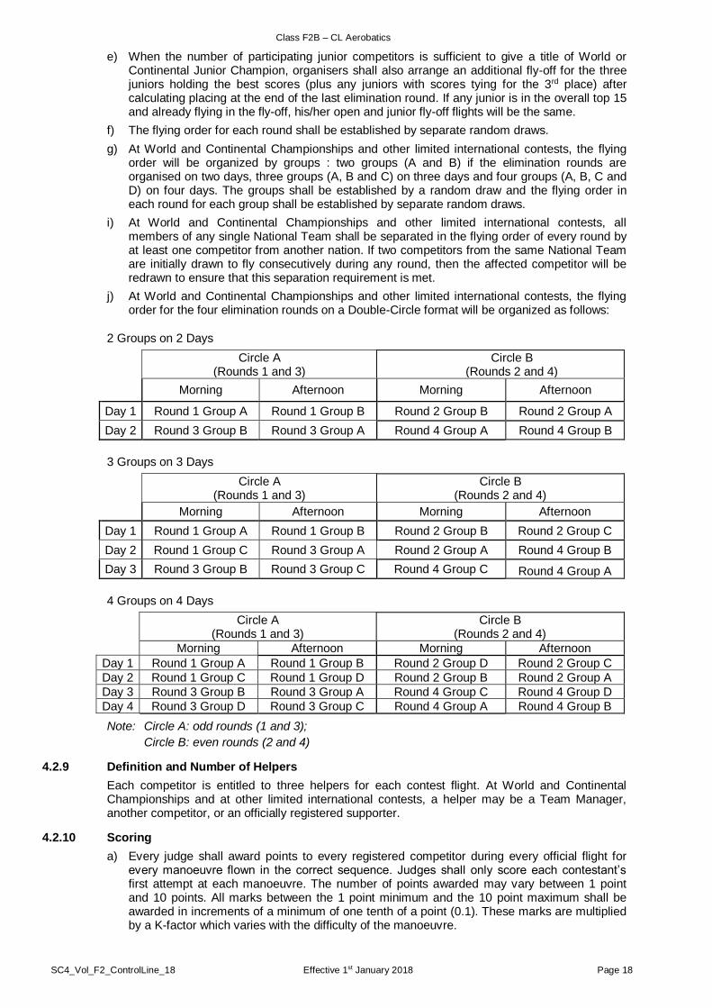
j) At World and Continental Championships and other limited international contests, the flying order for the four elimination rounds on a Double-Circle format will be organized as follows:
2 Groups on 2 Days
Circle A
(Rounds 1 and 3) Circle B
(Rounds 2 and 4)
Morning Afternoon Morning Afternoon
Day 1 Round 1 Group A Round 1 Group B Round 2 Group B Round 2 Group A
Day 2 Round 3 Group B Round 3 Group A Round 4 Group A Round 4 Group B
3 Groups on 3 Days
Circle A
(Rounds 1 and 3) Circle B
(Rounds 2 and 4)
Morning Afternoon Morning Afternoon
Day 1 Round 1 Group A Round 1 Group B Round 2 Group B Round 2 Group C
Day 2 Round 1 Group C Round 3 Group A Round 2 Group A Round 4 Group B
Day 3 Round 3 Group B Round 3 Group C Round 4 Group C Round 4 Group A
4 Groups on 4 Days
Circle A
(Rounds 1 and 3) Circle B
(Rounds 2 and 4)
Morning Afternoon Morning Afternoon
Day 1 Round 1 Group A Round 1 Group B Round 2 Group D Round 2 Group C
Day 2 Round 1 Group C Round 1 Group D Round 2 Group B Round 2 Group A
Day 3 Round 3 Group B Round 3 Group A Round 4 Group C Round 4 Group D
Day 4 Round 3 Group D Round 3 Group C Round 4 Group A Round 4 Group B
Note: Circle A: odd rounds (1 and 3);
Circle B: even rounds (2 and 4)
4.2.9 Definition and Number of Helpers
Each competitor is entitled to three helpers for each contest flight. At World and Continental Championships and at other limited international contests, a helper may be a Team Manager, another competitor, or an officially registered supporter.
4.2.10 Scoring
a) Every judge shall award points to every registered competitor during every official flight for every manoeuvre flown in the correct sequence. Judges shall only score each contestant’s first attempt at each manoeuvre. The number of points awarded may vary between 1 point and 10 points. All marks between the 1 point minimum and the 10 point maximum shall be awarded in increments of a minimum of one tenth of a point (0.1). These marks are multiplied by a K-factor which varies with the difficulty of the manoeuvre.
Class F2B – CL Aerobatics
SC4_Vol_F2_ControlLine_18 Effective 1st January 2018 Page 19
b) In the description of the manoeuvres (see 4.2.15.3 to 4.2.15.17), the first numbered paragraph, "Start of manoeuvre", is also the point at which the judges shall start officially observing the manoeuvre in order to award points; and the last numbered paragraph "End of manoeuvre" is also the point at which the judges shall stop officially observing the manoeuvre and stop awarding points.
Note: the descriptions of the manoeuvres also include un-numbered paragraphs marked "Recommended entry procedure" and "Recommended exit procedure". These are recommendations for use by the contestants only and judges shall not officially observe these procedures, nor shall they award any points at all for these procedures, regardless of whether or not they are performed in accordance with the recommendations.
c) All judges shall award a mark 0 (zero) for:
i) Manoeuvres omitted or not attempted at all.
ii) Manoeuvres started but not completed.
iii) Manoeuvres with an incorrect number of repeat figures (either too few or too many).
iv) Manoeuvres flown out of the sequence.
v) Manoeuvres flown without a minimum of 11/2 laps interval after the previous manoeuvre.
vi) Manoeuvres performed after the maximum flight time of 7 minutes has elapsed.
d) When a manoeuvre is omitted or not attempted at all, the remaining manoeuvres shall be scored provided they are attempted in the correct order.
e) When performed after the completion of the four-leaf clover manoeuvre but before the start of the landing manoeuvre, other manoeuvring shall be permitted. All such manoeuvring shall not be officially observed nor scored by the judges.
f) The mark 0 (zero) shall be awarded for the landing manoeuvre if the official timekeeper confirms that the model aircraft comes to a complete stop at the end of the ground roll after the 7 minutes total time allowed for an official flight has expired. The mark 0 (zero) points shall also be awarded for the landing manoeuvre if :
i) the model aircraft crashes ;
ii) or the model aircraft lands on its belly ;
iii) or the model aircraft lands upside-down ;
iv) or the model aircraft is fitted with a retractable landing gear and if this was not fully extended at the time of touch down, or if the retractable landing gear is apparently fully extended but if it collapses when touching down.;
v) or the model aircraft flips over at the moment of touching down.
Note: if the model aircraft flips over or noses-down during the ground rollout phase points may be awarded for the landing manoeuvre if in the opinion of the judges, the flip-over or nosing-down was due to adverse wind conditions, or poor ground surface conditions affecting what would otherwise be predicted as the model aircraft's normal ground roll after touching down.
g) If a crash interrupts an official flight then every judge shall score all completed manoeuvres up to and including the last manoeuvre that was completed before the crash occurred. All other manoeuvres remaining in the sequence including the manoeuvre in which the crash occurred) shall be awarded a mark 0 (zero).
h) In co-operation with the F2B Contest Director, the Head Judge shall ensure that all scores awarded to a contestant for the respective official flight shall be discarded and scored 0 (zero) points if either of the following occur:
i) the model aircraft fails the second official noise test (see paragraph 4.2.6).
ii) any part(s) of the model aircraft become detached from the model aircraft (intentionally or otherwise) at any time from the moment of release for the take-off manoeuvre until the moment that the model aircraft first touches down from the landing manoeuvre. This does not apply to any part(s) of the model aircraft which detached during a crash, or a flip over, a belly or upside down landing.
cont/…
Class F2B – CL Aerobatics
SC4_Vol_F2_ControlLine_18 Effective 1st January 2018 Page 20
4.2.11 Judging
a) Aerobatic judges will be responsible for observing each attempt at an official flight and to record their awarded score for each manoeuvre as it is completed. Once an official flight has begun the judges may, of their own accord, change their original position, but such position change shall not exceed a maximum of 1/8 of a lap ahead of or behind their original position as at the beginning of the respective official flight. Judges shall only change position during the 1½ intervening laps flown between manoeuvres and not while any manoeuvre is being flown.
b) At Single-Circle format contests, the organiser must appoint a panel of at least three judges. In the case of World and Continental Championships and other limited international contests the panel of judges must be increased to five.
c) At Double-Circle format contests, the organiser must appoint a panel of three judges for each contest flight circle. For the fly-off rounds (World and Continental Championships and other limited international contests), the panel of judges is increased to 6 judges.
d) For each panel of judges, one judge is selected as Head Judge.
e) At World and Continental Championships and other limited international contests, all the judges shall be selected from a list of persons proposed by the National Airsports Controls for their proficiency and experience and approved by the CIAM.
f) One of the judges at World and Continental Championships and other limited international contests must not have judged at the previous equivalent Championship.
g) In Open International contests, only two judges must be approved by CIAM for each panel of judges.
h) At World and Continental Championships and other limited international contests, all the judges must be of different nationalities. In Open International contests, the judges must be of at least two nationalities for each panel of judges.
i) Each judge shall be permanently appointed to judge at a specific contest flight circle for the duration of the contest, except at contests which include a fly-off. At contests which include a fly-off (World and Continental Championships and other limited international contests), judges shall be appointed to a specific contest flight circle for the duration of all elimination rounds.
j) All judges appointed to the judging panel assigned to each contest flight circle shall judge every contest flight scheduled for their respective contest flight circle. But this requirement may be relaxed in exceptional circumstances, such as, but not limited to a judge becoming sick during a contest. In such event, the F2B Contest Director and the Head Judge shall confer (also together with an FAI Jury member) regarding the replacement of the missing judge.
k) At World and Continental Championships and other limited entry international contests, there will be at least one judges’ calibration flight per contest day at each contest flight circle to be used. All such judges’ calibration flights shall take place before any contest flights are scheduled. All judges’ calibration flights shall include sufficient time for a judges' briefing before and judges' debriefing after each judges’ calibration flight. Said briefing and debriefing shall include the complete panel/s of judges and shall be held privately, with no contest organiser, official, or competitor present. The provision of judges’ calibration flights in Open International contests shall be optional but is recommended.
l) All contest organisers shall arrange at least one judges’ meal break per contest day. If the judging panel/s request it, extra time shall also be scheduled for additional judges' breaks (for example breaks of approximately 10 minutes duration at approximately 2 hourly intervals throughout each round).
m) In any contest, no judge shall be scheduled to judge more than 50 contest flights or perform a total of more than 10 hours of judging duty (whichever is the longer) within any single contest day. This time shall include the above judges’ calibration flight(s) but does not include the breaks.
cont/…

Class F2B – CL Aerobatics
SC4_Vol_F2_ControlLine_18 Effective 1st January 2018 Page 21
4.2.12 Classification
a) The score for each manoeuvre corresponds to the original mark multiplied by the respective K-factor. The resulting scores for each manoeuvre shall then be added together to produce a single total score per judge. The resulting single total scores of the judges are totalled and then divided by the number of judges. The result will be rounded down to two decimal places (to the nearest lower 1/100th) to produce the competitor’s final score per official flight.
Example: 945.9999 will be rounded down to 945.99
945.9911 will be rounded down to 945.99
b) In Open International contests, the final position reached by all registered competitors ("placings") shall be processed as follows:
i) At Single-Circle format contests, organisers shall take each competitor's two highest flight scores and add them together to produce the competitor’s final score for placing. In case of ties, the third flight score of the affected competitors shall be used to determine placing.
ii) At Double-Circle format contests, organisers shall take each competitor's highest score from each contest flight circle, add them together to produce the competitor’s final score for placing. In case of ties, the affected competitors' second highest score from any of the contest flight circles shall be used to determine placing.
iii) If, due to extraordinary circumstances, only two complete rounds were flown, then each competitor’s score from the two completed rounds shall be used to determine placings.
c) At World and Continental Championships and other limited entry international contests, score of each registered competitors ("placing") at the end of the last elimination round shall be processed as follows:
i) At Single-Circle format Championships, organisers shall take each competitor's two highest flight scores and add them together to produce the competitor’s score.
ii) At Double-Circle format Championships, organisers shall take each competitor's highest score from each contest flight circle, add them together to produce the competitor’s score.
iii) If, due to extraordinary circumstances, only two complete rounds were flown, then each competitor’s score from the two completed rounds shall be used.
The final placing of the finalists will be processed as follows : each competitor's two highest fly-off round scores shall be added together and the resulting total shall then be divided by two. The result shall be rounded down to two decimal places. In case of ties, the third fly-off score of the affected competitors shall be used to determine the final placings. If, due to extraordinary circumstances, only two complete fly-off rounds were flown then each competitor’s fly-off score from the two completed fly-off rounds shall be used for final placings.
The results of the specific junior fly-off will serve to rank those top juniors but will not affect the general results.
The classification of the non-finalists will be done according to their score at the end of the last elimination round. In case of ties:
i) at Single-Circle format Championships, the third flight score of the affected competitors shall be used to determine placings of the affected competitors ;
ii) at Double-Circle format Championships, second highest score from any of the contest flight circles shall be used to determine placings of the affected competitors.
In the case of a two way tie for 15th place at the end of the last elimination round, the following competitor is placed 17th; in the case of a three way tie for 15th place the following competitor is number 18th etc.
d) To establish the national scores for team classification add the numerical placing of the three team members of each nation. Teams are ranked according to the lowest numerical sum of placings to highest, with complete three-competitor teams ahead of two-competitor teams which in turn are ranked ahead one-competitor teams.
e) At World and Continental Championships and other limited entry international contests, facsimile copies of the judges’ original score sheets from each official flight shall be given to the respective Team Manager or Assistant Team Manager before the competitor’s next flight in the contest, or at the latest at the end of each round of the contest.

Class F2B – CL Aerobatics
SC4_Vol_F2_ControlLine_18 Effective 1st January 2018 Page 22
f) At all World Cup contests, facsimile copies of the judges score sheets from each official flight shall be given to the respective competitor before the competitor’s next flight in the contest or at the latest at the end of each round of the contest.
4.2.13 Starting Procedure
a) Each competitor shall be allowed 3 minutes preparation time to enter the circle, to place his model aircraft at the selected starting position, to position the judges and to prepare his motor(s) for starting.
b) The competitor may choose to start, warm-up and stop his motor(s) during the preparation time, and he must inform the timekeeper if it is his intention to do so.
c) Immediately after the preparation time he shall be allowed a 7 minutes flight time in which to complete his manoeuvres.
d) The preparation time shall start when the competitor is officially called to perform his contest flight
e) The timekeeper shall signal the beginning of the preparation time to the competitor and the judges.
f) The preparation time shall end and the Flight time shall start when:
i) The timekeeper registers that the 3 minutes preparation time has elapsed.
ii) The competitor gives a clear hand signal to the timekeeper, indicating that he is ready to start his motor(s).
iii) The competitor starts his motor(s) without giving a clear signal to the timekeeper.
iv) The competitor starts his motor(s) for warm-up without receiving permission from the timekeeper.
g) The timekeeper shall signal to the competitor and the judges when the flight time starts. If no hand signal is given by the competitor prior to starting his motor(s), or he starts his warm-up without receiving permission, then the timekeeper shall notify the judges of this.
h) The timing of an official flight shall stop the moment that the model aircraft has come to a full stop at the end of the ground roll that completes the Landing Manoeuvre.
i) The competitor shall remove his model aircraft, lines and handle from the flight circle immediately after he has completed his flight.
cont/…
Starting Procedure
Start of flight time
3 minutes for entering, placing of judges and
preparation for motor/s start
7 min official flight period
End ofjudging
Call toenter
Class F2B – CL Aerobatics
SC4_Vol_F2_ControlLine_18 Effective 1st January 2018 Page 23
4.2.14 Execution and Sequence of Manoeuvres
a) The sequence of manoeuvres with their corresponding K factor is :
1. Starting 0
2. Take-off 2
3. Reverse wing-over 8
4. Three consecutive inside loops 6
5. Two consecutive laps of inverted level flight 2
6. Three consecutive outside loops 6
7. Two consecutive inside square loops 12
8. Two consecutive outside square loops 12
9. Two consecutive inside triangular loops 14
10. Two consecutive horizontal eights 7
11. Two consecutive square horizontal eight 18
12. Two consecutive vertical eight 10
13 Hourglass 10
14. Two consecutive overhead figure eight 10
15. Four-leaf clover 8
16. Landing 5
b) All manoeuvres must be executed in the order of the list.
c) Every competitor shall leave at least 1½ laps (including the recommended entry and exit procedure detailed for each manoeuvre) to create a pause period between the end of one manoeuvre and the start of the next. The level portion of the 1½ intervening laps shall be flown at a height of between 1 and 3 metres. Judges shall not however officially observe any of these pause periods but instead shall use this time to enter the score awarded for the previous manoeuvre onto the competitor’s score sheet before the next manoeuvre is started.
4.2.15 Description of Manoeuvres
a) The diagrams of the manoeuvres displaying the pilot’s view are to be found in Annex 4J. They are an integral part of the rules and must be read in conjunction with the manoeuvre descriptions.
b) The F2B Judges' Guide is at Annex 4B.
4.2.15.1 Terminology and Wording
a) Wording and phraseology used in the F2B manoeuvre descriptions define the track of a control line model aircraft flying anticlockwise on the surface of a hemisphere.
Wording Definition
Manoeuvre Means the full total of figures and segments necessary to complete the manoeuvre marked under a separate numbered heading with bold type. For example, the take-off manoeuvre, the three consecutive inside loops manoeuvre, and the single four-leaf clover manoeuvre, are all referred to as a single whole manoeuvre throughout this text.
Figure Means a shape, which makes up a separately recognisable complete part of a whole manoeuvre. For example, the first loop of the three consecutive inside loops manoeuvre is referred to as a figure; but the first loop which makes the first half of the first complete figure eight in the two consecutive overhead eight manoeuvre is not referred to as a figure.
Segment Means a specifically defined part of a figure (or of a whole manoeuvre) in which certain particular points are detailed. For example, the first loop which makes the first half of the first complete figure eight in the two consecutive overhead eight manoeuvre is referred to as a segment.
cont/…
Class F2B – CL Aerobatics
SC4_Vol_F2_ControlLine_18 Effective 1st January 2018 Page 24
Upright Means the model aircraft flying in its "normal" upright attitude (that is: with its landing gear nearest to the ground).
Inverted: Means the model aircraft flying in an attitude which is the reverse of upright flight (colloquially, the model aircraft is "flying on its back", is "flying upside-down", or is “flying inverted").
Flight hemisphere: Means a half globe shape whose base is level above the ground.
Parallel: Means an imaginary line on the surface of the flight hemisphere equidistant to the equator of the flight hemisphere and marking the latitude.
Base: Means the base of the flight hemisphere. This lies at a height of 1.5m above the centre of the flight circle.
Level: Means at right angles to the direction aligned with the direction of the force of gravity, as materialised with a plumb line.
Flight circle: Means a horizontal circle whose radius is equal to the flight radius.
Horizontal: Means flight along or parallel to the base
Vertical: Means flight at right angles to the base, along an imaginary circle on the surface of the flight hemisphere marking the longitude.
Straight line Straight line: A great circle path or part thereof.
Is used throughout this text in their original dictionary definition sense (that is: something, which lasts only for a very brief period of time). So, for example, the very short period during which the model aircraft is required to be in a vertically-banked "knife-edge" attitude above the competitor’s head during the two consecutive overhead eights manoeuvre is described in this text as "momentarily".
Lateral reference This is an imaginary line drawn at right angles (90 degrees) to the horizontal and is used as a reference line when flying and scoring the size, positioning, symmetry and the superimposition of various figures and manoeuvres.
Wingover path Means the vertical climbing and diving flight path defined as a segment of the single reverse wingover manoeuvre.
4.2.15.2 Starting
Engines may be started manually or by the use of an electric or mechanical starter.
4.2.15.3 Take-off Manoeuvre
a) Start of manoeuvre:
The moment when the model aircraft begins its ground roll. The model aircraft must take off from the ground.
To prevent uncontrolled movement or flight of the model caused by an accidental motor run, electric powered model aircraft must be restrained by the pilot, by an assistant, or by a mechanical device until the pilot is holding the handle.
b) Ground roll and lift off segment:
Before lifting off the model aircraft should run along the ground for a distance of not less than 4.5 metres and not more than 1/4 of a lap. The lift-off should be smooth, meaning without a "sudden jump" into the air.
c) Take-off and levelling-off segment:
The model aircraft should maintain a constant rate of climb until reaching the base of the flight hemisphere. The base lies horizontal at a height of 1.5 m above the centre of the flight circle. The point of changing from climbing flight to level flight should occur exactly over the point of release at the beginning of the take off ground roll. The transition into upright level flight should be smooth and gentle with no sudden changes.
d) Two laps of upright level flight segment:
After levelling off, the model aircraft should maintain level flight at the height of the base (+/- 30 cm) and should fly 2 complete laps of stable and smooth normal upright flight without deviation.
cont/…
Momentary or momentarily
Class F2B – CL Aerobatics
SC4_Vol_F2_ControlLine_18 Effective 1st January 2018 Page 25
e) End of manoeuvre:
At the end of the third lap, exactly overhead the point of beginning the take-off ground roll.
Recommended exit procedure: Continue normal upright level flight at the height of the base.
4.2.15.4 Reverse Wing-over Manoeuvre
Note: All turns in this manoeuvre should be between 1.5 metres and 2.1 metres radius.
Recommended entry procedure: From normal upright level flight at the height of the base.
a) Start of manoeuvre:
At the beginning of the 1st turn from normal upright level flight at the height of the base, (+/- 30 cm) into a vertical climb.
b) The first vertical climb and dive segment:
The model aircraft turns sharply into a vertical climb and should then maintain this climb at right angles to the base. It should pass over the flyer’s head and then continue into a dive that is also at right angles to the base, until reaching the 2nd turn, at which point the model aircraft should turn sharply from its dive into inverted level flight at the height of the base, (+/- 30 cm)
c) The inverted horizontal level flight segment:
After recovery from the vertical dive and until the start of the 2nd vertical climb, the model aircraft should fly a segment of steady inverted flight along the base (+/- 30 cm), with no deviations from the established height. The length of this segment, including turns, should be ½ of a lap.
d) The second vertical climb and dive segment:
At the 2nd vertical climb, the model aircraft should turn sharply into a vertical climb and should then maintain a climb that is at right angles to the base. The model aircraft should pass over the flyer’s head and then continue into a dive that is also at right angles to the base. At the 4th turn, the model aircraft should turn sharply from its dive into normal level upright flight at the height of the base (+/- 30 cm). The point where the model aircraft starts its recovery turn into normal level upright flight at the end of the completed manoeuvre should be exactly opposite the point where the model aircraft first reached the 2nd vertical climb at the start of the manoeuvre, and at the same height.
e) End of manoeuvre:
the end of the 4th turn (recovery to normal upright level flight).
Recommended exit procedure: Continue normal upright level flight at the height of the base.
4.2.15.5 Three Consecutive Inside Loops Manoeuvre
Manoeuvre size: The tops of the loops are tangent to the 45 degree parallel.
Recommended entry procedure: The manoeuvre is entered from normal level upright flight at the height of the base.
a) Start of manoeuvre:
At the start of the first loop, as the model aircraft departs normal upright level flight.
b) The first loop figure:
From normal upright level flight at the height of the base, the model aircraft should fly upwards along a circular flight path until reaching the 45° parallel. At that point, the model aircraft should be inverted. It should continue along its circular flight path downwards until reaching the bottom of the loop at the height of the base (+/- 30 cm), in upright flight. When the model aircraft reaches a vertical attitude for the first time, this has defined the lateral reference for the whole manoeuvre.
c) The second and third loop figures:
The model aircraft should follow a flight path exactly as described above. The second and third loops should be placed in exactly the same position as the first loop, and should be of exactly the same size.
d) End of manoeuvre:
At the end of the third loop, as the model aircraft completes recovery into normal upright level flight.
Recommended exit procedure: The model aircraft should continue for another ½ loop, recovering inverted and descending to the normal inverted flight level within ½ a lap, remaining inverted at the height of the base.

Class F2B – CL Aerobatics
SC4_Vol_F2_ControlLine_18 Effective 1st January 2018 Page 26
4.2.15.6 Two Consecutive Laps of Inverted Level Flight Manoeuvre
Recommended entry procedure: The manoeuvre is entered from inverted level flight at the height of the base.
a) Start of manoeuvre:
At the start of the third lap after the exit from the previous manoeuvre.
b) Two laps of inverted flight:
The model aircraft should maintain 2 complete laps of smooth and stable inverted flight at the height of the base (+/- 30 cm). The model should not deviate from the established flight height.
c) End of manoeuvre:
At the end of the fourth lap after the exit from the previous manoeuvre.
Recommended exit procedure: Continue inverted flight, remaining at the height of the base until entry into the next manoeuvre.
4.2.15.7 Three Consecutive Outside Loops Manoeuvre
Manoeuvre size: The tops of the loops are tangent to the 45 degree parallel.
Recommended entry procedure: From inverted level flight at the height of the base.
a) Start of manoeuvre:
The manoeuvre starts at the height of the base where the model aircraft begins the 1st loop.
b) The first loop figure:
From inverted level flight at the height of the base, the model aircraft should fly upwards along a circular path until reaching the 45 degrees parallel. At this point it should be upright. The aircraft should continue its circular flight path downwards until passing the bottom at the height of the base (+/- 30 cm) in inverted flight. The whole flight path should be circular and smooth with no deviations or flat spots. When the model aircraft reaches a vertical attitude for the 1st time, this has defined the lateral reference for the whole manoeuvre.
c) The second and third loop figures:
The model aircraft should follow a flight path exactly as described above. The second and third loops should be placed in exactly the same position as the first loop, and should be of exactly the same size.
d) End of manoeuvre:
At the end of the 3rd loop, as the model aircraft reaches the height of the base, in inverted level flight.
Recommended exit procedure: Continue for another half loop, recovering to upright flight and then descending to the normal upright level height at the height of the base.
4.2.15.8 Two Consecutive Inside Square Loops Manoeuvre
Note: All turns in this manoeuvre should be between 1.5 metres and 2.1 metres radius.
Manoeuvre size: The tops of the loops are flown along the 45 degree parallel. Width is ⅛ of a lap.
Recommended entry procedure: From normal upright level flight along the base.
a) Start of manoeuvre:
The manoeuvre starts at the point where the model aircraft begins its 1st turn into a vertical climb from normal level upright flight along the base (+/- 30 cm).
b) First loop figure – 1st turn and climbing segment:
The model aircraft should turn sharply into, and then maintain a climb that is at right angles to the base.
c) First loop figure - 2nd turn and top segment:
The model aircraft should turn sharply into, and then maintain inverted level flight along the 45 degree parallel.
d) First loop figure – 3rd turn and diving segment:
The aircraft should turn sharply into, and then maintain, a dive that is at right angles to the base.
cont/…

Class F2B – CL Aerobatics
SC4_Vol_F2_ControlLine_18 Effective 1st January 2018 Page 27
e) First loop figure – 4th turn and bottom segment:
The 1st loop is completed when the model aircraft turns sharply into, and then maintains upright level flight along the base (+/- 30 cm). The total length of the bottom segment, including both turns, should be ⅛ of a lap.
f) The second loop figure:
The model aircraft should follow a flight path exactly as described in the segments above. The second loop should be placed in exactly the same position as the first loop, and should be of exactly the same size.
g) End of manoeuvre:
The manoeuvre is completed in normal level upright flight along the base at the point where the model aircraft started its 1st turn into a vertical climb at the beginning of the complete manoeuvre.
Recommended exit procedure: Maintain normal upright level flight along the base.
4.2.15.9 Two Consecutive Outside Square Loops Manoeuvre
Note: All turns in this manoeuvre should be between 1.5 metres and 2.1 metres radius.
Manoeuvre size: The tops of the loops are flown along the 45 degree parallel. Width is ⅛ of a lap.
Recommended entry procedure: Use ¾ of a lap to climb to the height of the 45 degree parallel. Proceed along the 45 degree parallel for ⅛ of a lap.
a) Start of manoeuvre:
The manoeuvre starts at the point where the model aircraft begins its 1st turn into a vertical dive from the 45 degree parallel.
b) First loop figure - first turn and diving segment:
The model aircraft should turn sharply into, and then maintain a dive that is at right angles to the base.
c) First loop figure - 2nd turn and bottom segment:
At the height of the base, the model aircraft should turn sharply into, and then maintain inverted level flight along the base (+/- 30 cm) without any deviation. The total length of the bottom segment, including both turns, should be ⅛ of a lap.
d) First loop figure - 3rd turn and climbing segment:
The model aircraft should then turn sharply into, and then maintain a climb that is at right angles to the base.
e) First loop figure - 4th turn and top segment:
The model aircraft should turn sharply into, and then maintain upright level flight along the 45 degree parallel.
f) The second loop figure:
The model aircraft should follow a flight path exactly as described in the segments above. The second loop should be placed in exactly the same position as the first loop, and should be of exactly the same size.
g) End of manoeuvre:
The manoeuvre is completed in upright level flight on the 45 degree parallel at the same point where the model aircraft started its 1st turn at the beginning of the complete manoeuvre.
Recommended exit procedure: Maintain upright level flight along the 45 degree parallel for at least 5.0 m after the end of the manoeuvre and then descend to normal upright level flight at the height of the base within approximately ½ a lap.
cont/…

Class F2B – CL Aerobatics
SC4_Vol_F2_ControlLine_18 Effective 1st January 2018 Page 28
4.2.15.10 Two Consecutive Inside Triangular Loops Manoeuvre
Note: All turns in this manoeuvre should be between 1.5 metres and 2.1 metres radius. In each turn the model aircraft should change its angle of pitch attitude by approximately 120 degrees.
Manoeuvre size: The top turn is tangent to the 45 degree parallel and the width is slightly more than ⅛ of a lap.
Recommended entry procedure: From normal level upright flight along the base.
a) Start of manoeuvre:
The manoeuvre starts when the model aircraft begins its 1st turn from normal level upright flight along the base (+/- 30 cm).
b) First triangle figure – 1st turn and climb segment:
The model aircraft should turn sharply into an inverted climb at 30 degrees beyond vertical in relation to the base and maintain this flight path until starting the 2nd turn.
c) First triangle figure – 2nd turn and dive segment:
The model aircraft should then turn sharply into an inverted dive at an angle of 30 degrees to vertical. The height reached during this 2nd turn should be equal to the height of the 45 degree parallel. After completing the 2nd turn, the model aircraft should maintain this flight path until starting the 3rd turn.
d) First triangle figure - 3rd and bottom segment:
The aircraft should then turn sharply into upright level flight along the base (+/- 30 cm).
e) The second triangular loop figure:
The model aircraft should follow a flight path exactly as described in the three segments above. The second loop should be placed in exactly the same position as the first loop, and should be of exactly the same size.
f) End of manoeuvre:
With the model aircraft in normal upright level flight, at the point where the model aircraft started its first turn at the start of the complete manoeuvre.
Recommended exit procedure: Continue normal upright level flight along the base.
4.2.15.11 Two Consecutive Horizontal Eights Manoeuvre
Manoeuvre size: The tops of the loops are tangent to the 45 degree parallel.
Recommended entry procedure: From normal upright level flight at the height of the base.
a) Start of manoeuvre:
The manoeuvre starts when the model aircraft passes the intersection point for the first time.
Note: When the model aircraft reaches a vertical climbing attitude for the first time, this has defined the intersection point for the whole manoeuvre (ie after ¼ of the 1st loop of the 1st eight has been flown).
b) The first eight figure - first inside loop segment:
From normal upright level flight, the model aircraft should fly upwards along a circular flight path to the height of the 45 degree parallel, at which point it should be inverted. The model aircraft should continue its circular flight path downwards until reaching normal level upright flight at the height of the base (+/- 30 cm), at which point it should be upright. The model aircraft should then continue its circular flight path for a further ¼ of a loop until reaching the intersection point.
Note: The intersection point first defined by the model aircraft at the beginning of this manoeuvre should be maintained throughout the whole of the manoeuvre. At the time of passing through the intersection point and transitioning to the 1st outside loop, the model aircraft should be momentarily in a vertical nose-up attitude, but should not visibly travel along a vertical climbing flight path.
c) The first eight figure – the outside loop segment (actually one complete loop from the intersection point onwards):
After passing through the intersection point, the model aircraft should continue to fly, without interruption, a complete outside loop by flying upwards along a circular flight path to the height of the 45 degree parallel, at which point the model aircraft should be upright. It should then continue its circular flight path downwards until reaching the height of the base (+/- 30 cm) in inverted flight. The model aircraft should then continue its circular flight path for a further ¼ of

Class F2B – CL Aerobatics
SC4_Vol_F2_ControlLine_18 Effective 1st January 2018 Page 29
a loop until reaching the intersection point, where it should be momentarily vertical.
d) The second complete eight figure:
The model aircraft should follow a flight path exactly as set out in the individual segments above. The second figure eight should be flown in exactly the same position and should be of exactly the same size as the first eight figure.
e) End of manoeuvre:
The manoeuvre is completed when the model aircraft completes the 2nd eight figure, when passing the intersection point in a vertical climb for the 5th and last time.
Recommended exit procedure: After passing the intersection point for the last time, continue the circular flight path for approximately a further 135 degrees of arc, until levelling out into normal upright level flight at the height of the base.
4.2.15.12 Two Consecutive Horizontal Square Eights Manoeuvre
Note: All turns in this manoeuvre should be between 1.5 metres and 2.1 metres radius.
Manoeuvre size: The top segments of the loops are flown along the 45 degree parallel. Width is ¼ of a lap.
Recommended entry procedure: From normal upright level flight at the height of the base.
a) Start of manoeuvre:
With the model aircraft in normal upright level flight along the base (+/- 30 cm), from the point where the model aircraft starts its first turn upwards into a vertical climb for the first time.
Note: when the model aircraft reaches a vertical climbing attitude for the first time, this has defined the intersection line for the whole manoeuvre.
b) The first eight figure – the 1st climbing turn and vertical climbing segment of the 1st (inside) square loop:
The model aircraft should turn sharply into a vertical climb, reaching and maintaining a flight path that is at right angles to the base.
c) The first eight figure – the 2nd turn and top segment of the 1st (inside) square loop:
The model aircraft should turn sharply into inverted level flight to reach the height of the 45 degrees parallel as it becomes inverted. The top segment should be flown along the 45 degree parallel.
d) The first eight figure - the 3rd turn and vertical dive segment of the 1st (inside) square loop:
The model aircraft should turn sharply into a vertical dive, reaching and maintaining a flight path that is at right angles to the base.
e) The first eight figure - the 4th turn and bottom segment of the 1st (inside) square loop:
The model aircraft should turn sharply into upright level flight and this section should be flown along the base (+/- 30 cm). The length of the whole bottom segment, including both turns, should be ⅛ of a lap.
f) The first eight figure - the 1st climbing turn and vertical climb segment of the 2nd (outside) square loop:
At the end of the previous segment (paragraph e) above), the model aircraft should turn sharply into a vertical climb, reaching and maintaining a flight path which is at right angles to the base. This flight path should be in exactly the same position as defined by the model aircraft at the beginning of the manoeuvre (paragraph a) above).
g) The first eight figure - the 2nd turn and top segment of the 2nd (outside) square loop:
The model aircraft should turn sharply into upright level flight to reach the height of the 45 degree parallel as it becomes level. The top segment should be flown along the 45 degree parallel.
h) The first eight figure - the 3rd turn vertical dive segment of the 2nd (outside) square loop:
The model aircraft should turn sharply into a vertical dive, reaching and maintaining a flight path that is at right angles to the base.
i) The first eight figure - the 4th turn and bottom segment of the 2nd (outside) square loop:
The model aircraft should turn sharply into inverted level flight, and this section should be flown along the base (+/- 30 cm). The length of the whole bottom segment, including both turns, should be ⅛ of a lap.
cont/…
Class F2B – CL Aerobatics
SC4_Vol_F2_ControlLine_18 Effective 1st January 2018 Page 30
j) The second eight figure:
The model aircraft should follow a flight path exactly as set out in the individual segments above. The second eight figure should be flown in exactly the same position and should be of exactly the same size as the first eight figure.
k) The final turn and last vertical climb exit from manoeuvre segment:
At the end of the 2nd bottom segment of the 4th loop the model aircraft should again turn sharply into a vertical climb, reaching and maintaining a flight path which is at right angles to the base. This flight path should be in exactly the same position as defined by the model aircraft at the start of the manoeuvre (paragraphs a) and b) above).
l) End of manoeuvre:
At the end of the last vertical climb segment, before turning into normal upright exit flight along the 45 degree parallel.
Recommended exit procedure: Complete a further 90 degrees turn into upright level flight along the 45 degree parallel. Maintain this flight path until clear of the left hand side of the left hand loop by approximately 5.0 metres then make a turn into a dive of approximately 45 degrees nose down attitude. Recover into normal upright level flight at the height of the base.
4.2.15.13 Two Consecutive Vertical Eights Manoeuvre
Manoeuvre size: Height is 90 degrees line elevation angle to the base.
Recommended entry procedure: From normal upright level flight at the height of the base, fly upward along a circular flight path to reach the height of the 45 degree parallel. At this point the model aircraft should be inverted.
a) Start of manoeuvre:
After the model aircraft has flown the 1st half of an inside loop, as it passes through the intersection point for the first time.
Note: the intersection of the whole manoeuvre is defined when the model aircraft passes through inverted level flight at the height of the 45 degree parallel for the first time.
b) The first eight figure – the 1st (inside loop) segment:
As the model aircraft passes through the intersection point for the first time it should continue to fly a circular inside loop. The bottom of this loop should be at the height of the base (+/- 30 cm). The loop should be completed by the model aircraft continuing this circular flight path until reaching an inverted attitude at the height of the 45 degree parallel.
c) The first eight figure - the 2nd (outside loop) segment:
As it passes through the intersection point the model aircraft should continue flying a circular outside loop. The bottom of this 2nd loop should be at the height of the 45 degree parallel and the top should be at 90 degree line elevation angle.
Note: the flight path of this 2nd loop should touch the intersection point, and this intersection point should be maintained throughout the entire manoeuvre. At the time of passing through the intersection point and then transitioning into the 2nd (outside) loop, the model aircraft should be momentarily in a level inverted flight attitude but should not visibly follow a straight flight path. The model aircraft should neither climb nor dive during this momentary period of inverted flight. In addition, the centres of both loops should be positioned on an imaginary line drawn upwards from the base at right angles.
d) The second eight figure:
The model aircraft should follow a flight path exactly as set out in the individual segments above. The 2nd eight figure should be flown in exactly the same position and should be of exactly the same size as the 1st eight figure.
e) End of manoeuvre:
As the model aircraft completes the 2nd eight figure, at the moment when it reaches inverted level flight at the height of the 45 degree parallel.
Recommended exit procedure: Continue for a further ½ inside loop until the model aircraft is upright at the height of the base and then continue in normal level upright flight.
cont/…
Class F2B – CL Aerobatics
SC4_Vol_F2_ControlLine_18 Effective 1st January 2018 Page 31
4.2.15.14 Hourglass Manoeuvre
Note: All turns in this manoeuvre should be between 1.5 metres and 2.1 metres radius.
In each turn the model aircraft should change its angle of pitch attitude by approximately 120 degrees.
Manoeuvre size: Height is 90 degrees line elevation angle to the base. Width is slightly more than ⅛ of a lap.
Recommended entry procedure: From normal upright level flight at the height of the base.
a) Start of manoeuvre:
The manoeuvre starts from the point where the model aircraft starts its 1st turn from the base (+/- 30 cm) into a climb for the first time.
b) The first turn and inverted climb segment:
The model aircraft should turn sharply into, and then maintain an inverted climb with a flight path angled at approx. 30 degrees past the right angle (relative to the base). The climb should be continued until the model reaches the wingover flight path, positioned at 90 degrees to the centre line axis of the whole manoeuvre, where the model aircraft makes a sharp outside turn to follow this wingover flight path, and the middle point of this flight path should be positioned directly above the centre of the circle.
c) The overhead and dive 2nd turn, wingover, and 3rd turn segment:
The length of the overhead segment, including its 2 turns, should be slightly more than ⅛ of a lap. This segment should be followed by a sharp outside turn through approx. 120 degrees into an inverted dive, which is maintained on a flight path angled at approx. 30 degrees to the base.
d) The intersection:
The intersection of the climb and dive flight paths should be at the height of the 45 degree parallel
e) The fourth turn and bottom level flight segment:
At the completion of the dive segment, the model aircraft should turn sharply into normal upright level flight at the height of the base (+/- 30 cm). The bottom segment shall be flown along the base maintaining the established height. The length of this segment, including 2 turns, should be slightly more than ⅛ of a lap
f) Symmetry of the complete manoeuvre:
The complete figure should be flown symmetrically in relation to its vertical centre line axis and this centre line axis should be at right angles to the base.
g) End of manoeuvre…the complete manoeuvre.
Recommended exit procedure: Continue in normal upright level flight along the base.
4.2.15.15 Two Consecutive Overhead Eights Manoeuvre
Manoeuvre size: The top of loops shall be directly over the centre of the circle and lowest points of both loops must being tangential to the 45 degree parallel.
Recommended entry procedure: From normal upright level flight the model aircraft should climb in a Wingover flight path to a point directly over the centre of the circle.
a) Start of manoeuvre:
As the model aircraft passes through the overhead point for the first time.
b) The intersection:
The intersection point of the complete manoeuvre should be directly over the centre of the circle and should be maintained throughout this entire manoeuvre.
c) The first (inside loop) segment:
From the overhead position, the model aircraft should fly a circular inside loop, returning to the overhead (intersection) point. The right hand bottom of this loop should be at the height of the 45 degree parallel. This loop should be positioned symmetrically on an imaginary line on the face of the flying hemisphere, which is drawn upwards at 90 degrees to the axis of the model aircraft’s wingover climb to the intersection point.
cont/…

Class F2B – CL Aerobatics
SC4_Vol_F2_ControlLine_18 Effective 1st January 2018 Page 32
d) The passage through the intersection point and transition into the 2nd (outside) loop segment:
As the model aircraft passes through the intersection/overhead point, it should smoothly transition into the 2nd (outside) loop without flat spots or deviations. At the point of flying directly above the centre of the circle the model aircraft should be momentarily in a "knife edge" position with a line elevation angle of 90 degrees.
e) The second (outside loop) segment:
From the overhead position, the model aircraft should transition smoothly into the 2nd circular (outside) loop, completing this loop when it has again returned to the overhead/ intersection point. The left hand bottom of this loop should be at the height of the 45 degree parallel. This loop should be positioned symmetrically on an imaginary line on the face of the flying hemisphere, which is drawn upwards at 90 degrees to the axis of the model aircraft’s wingover climb to the intersection point.
f) The second eight figure:
The model aircraft should fly the 2nd eight figure exactly as set out in the individual segments above and this 2nd eight figure should be flown in the same position and of the same size as the 1st eight figure.
Recommended exit procedure: Continue by completing the 2nd (diving) half of the wingover flight path that was flown to start the manoeuvre. Recover into normal upright level flight at the height of the base.
4.2.15.16 Four-leaf Clover Manoeuvre
Manoeuvre size: Height 90 degrees line elevation angle; width ¼ lap. All loops are to be flown as a true arc without visible deviations from a circular flight path.
Recommended entry procedure: Use ¾ of a lap to climb to a height of 42 degrees line elevation angle above the base and maintain this height in upright level flight for ⅛ of a lap. Fly ¼ of an inside loop to arrive at the point of entry.
a) Start of manoeuvre:
The manoeuvre starts at the 9 o’clock point of entry into the 1st loop segment.
b) The first ¾ of an inside loop segment: It is a circular arc of 270 degrees.
The top of this 1st loop should be tangential to the wingover path located at 90 degrees to the centre line axis of the whole manoeuvre. The model aircraft should recover into upright level flight at a height of 42 degrees line elevation angle above the base. This loop should be positioned tangentially to an imaginary vertical line drawn upwards at right angles to the base. The lateral position of this line is determined when the model aircraft reaches a vertical attitude for the first time and this imaginary line then becomes the lateral reference for the whole manoeuvre.
c) The upright level flight horizontal segment:
It begins at the 42 degree elevation point on the 1st loop. A straight line path is flown from this point to the 42 degree elevation point on the 2nd loop in upright level flight. The length of this segment should be equal to the diameter of the 1st loop.
d) The second outside ¾ of a loop segment:
It is flown as a true arc without visible deviations from a circular flight path. The bottom of this loop should be at the height of the base (+/- 30 cm). This ¾ loop should end with the model aircraft entering a vertical climb along the lateral reference established in the 1st.
e) The first vertical climb segment:
The model aircraft should then climb vertically at right angles to the base. The length of this segment should be equal to the diameter of the 1st loop.
f) The third outside ¾ of a loop segment:
It should be flown as a true arc without visible deviations from a circular flight path and the bottom should be at the height of the 42 degree line elevation. This ¾ loop should end with the model aircraft recovering to inverted level flight at the height of the 42 degree line elevation angle.
g) The inverted horizontal flight segment:
It is flown with the model aircraft following an inverted flight path which is straight from the 42 degree elevation point on the 3rd loop to the 42 degree elevation point on the 4th loop. The length of this segment should be equal to the diameter of the 1st loop.
cont/…

Class F2B – CL Aerobatics
SC4_Vol_F2_ControlLine_18 Effective 1st January 2018 Page 33
h) The fourth (inside) ¾ of a loop segment:
It should be flown as a true arc without visible deviations from a circular flight path and the bottom should be at the height of the base (+/- 30 cm). This ¾ loop should end with the model aircraft entering a vertical climb along the line of lateral reference established in the 1st loop.
i) The second climb segment:
The model aircraft should climb vertically at right angles to the base.
j) End of manoeuvre:
The manoeuvre ends at the end of the last vertical climb, as the model aircraft passes through a point above the centre of the circle.
Recommended exit procedure: Continue along the wingover path from the last vertical climb into a vertical dive before recovering into normal upright level flight at the base. Other manoeuvres after the completion of the Clover leaf are permissible.
4.2.15.17 Landing Manoeuvre
Recommended entry procedure: The manoeuvre is entered from normal upright level flight at the height of the base.
a) Start of manoeuvre:
As the model aircraft leaves level flight at the height of the base (+/- 30 cm) and with the motor/s and propeller/s stopped.
Note: For the purpose of this rule, the word “stopped” describes a situation where the blades of the propeller(s) are actually at a standstill or are rotating so slowly that the individual blades can clearly be seen by an observer.
b) The descent segment:
The model should fly for 1 full gliding lap with the motor/s and propeller/s stopped. This lap is measured from the start of the descent from the height of the base (+/-30cm) until the point of touchdown. The model should continuously descend from level flight to touchdown with no deviation from a straight flight path. The touch down itself should be smooth and either a “2 point” or a “3 point” touch down shall be judged as equally correct.
c) End of manoeuvre:
The manoeuvre is complete when the model aircraft comes to a complete stop after touching down at the end of the ground roll which is clearly in a forwards direction and in line with its normal flight motion. The length of the ground roll shall not exceed one lap.
At the end of the ground roll, electric powered model aircraft must be restrained by an assistant until the power system is secured against accidental motor start. The pilot must remain in the centre of the circle and he must not release the control handle until the model aircraft has been restrained. Failure to comply will result in the loss of all landing points.

SC4_Vol_F2_ControlLine_18 Effective 1st January 2018 Page 34
PAGE DELIBERATELY LEFT BLANK

Class F2C – CL Team Racing
SC4_Vol_F2_ControlLine_18 Effective 1st January 2018 Page 35
4.3 CLASS F2C – CL TEAM RACING
4.3.1. Team Racing Event
A team racing event is a contest where all races start with three model aircraft (hereinafter called
‘the model’) except when, in exceptional cases, a race may begin with two or one model(s). The
models are flown simultaneously in the same circuit, for a specified number of laps. The
competitor’s contest result is determined by a series of qualifying, semi-final, and final race times.
The conduct of the contest is controlled by a Panel of Judges (hereinafter called ‘the Judges’). The
Judges may use video recording equipment, located in the Judge’s Tower, to monitor the pilots and
the pilot circle. At the discretion of the Judges this official recorded video can be used, after the
race, as a judging aid.
Specific requirements include:
a) Team
i Each team consists of one pilot and one mechanic. No member of a team may be a
member of another team.
ii The pilot’s only function is to control the model and during the race, while his model’s
engine is running, he must remain in the centre circle.
iii The mechanic’s only function is to fuel, adjust, and start the model’s engine and during
the race he must remain outside the flight circle. The engine must be started by flicking
the propeller by hand.
iv During practice and races, the mechanic must wear a safety helmet, with a fastened
chinstrap, strong enough to withstand the impact of a flying model. The pilot must have a
safety strap connecting his wrist to the control handle.
b) Race
i Qualifying and semi-final races are run over 100 laps (10 km); two pitstops (landing for
refuelling) are mandatory. The final race is run over 200 laps (20 km); four pitstops are
mandatory.
ii Each team’s race begins with a ‘start’ signal and finishes when the first condition of the
five listed below is met:
a) All models have completed the required laps, or
b) the team is unable to continue racing, or
c) the team has been disqualified, or
d) when the judges declare “Stop racing – safety” or
e) the race maximum time limit has been reached.
iii The maximum time limit of a race is 6 minutes for qualifying and semi-final races, and 12
minutes for the final race.
iv Each team’s result is registered for that race.
4.3.2. Team Racing Site
a) A team racing site consists of four concentric circles marked, in contrasting colour, on a flat,
prepared surface of concrete, asphalt, terrazzo, etc as described in Annex 4F- the Control line
Organisers Guide.
b) The flight circle is a 19.6 m radius solid line that defines the model’s ‘landing zone’ (Centre Line
of model inside the circle) and the model’s ‘pitting areas’ (outside the circle). The circle is
divided into six equally-spaced (60 degrees apart) sectors with each sector marked by two lines,
one metre apart, on the outside of the flight circle to define the six ‘pitting areas’.
c) The safety circle is a 19.1 m radius broken line that defines the point beyond which the pitman
is not permitted to reach to retrieve a model.
d) The centre circle is a 3 m radius solid line: the pilots may not put a foot outside the line except
during the start and at pit stops. The centre of this circle shall be marked with a reference
contrasting colour spot of 0.3 m diameter.
e) The inner circle is a 2 m radius broken line (marked in a contrasting colour to the centre circle)
that is a reference circle for the pilots.
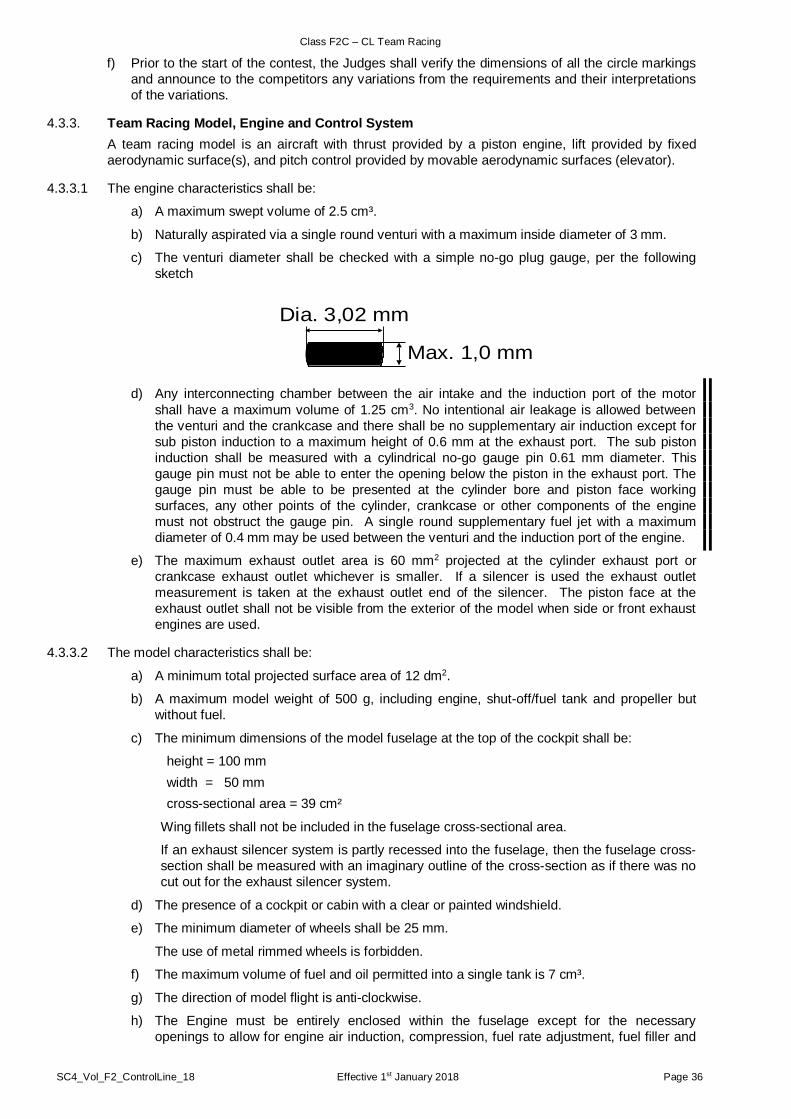
Class F2C – CL Team Racing
SC4_Vol_F2_ControlLine_18 Effective 1st January 2018 Page 36
f) Prior to the start of the contest, the Judges shall verify the dimensions of all the circle markings
and announce to the competitors any variations from the requirements and their interpretations
of the variations.
4.3.3. Team Racing Model, Engine and Control System
A team racing model is an aircraft with thrust provided by a piston engine, lift provided by fixed
aerodynamic surface(s), and pitch control provided by movable aerodynamic surfaces (elevator).
4.3.3.1 The engine characteristics shall be:
a) A maximum swept volume of 2.5 cm³.
b) Naturally aspirated via a single round venturi with a maximum inside diameter of 3 mm.
c) The venturi diameter shall be checked with a simple no-go plug gauge, per the following
sketch
d) Any interconnecting chamber between the air intake and the induction port of the motor
shall have a maximum volume of 1.25 cm3. No intentional air leakage is allowed between
the venturi and the crankcase and there shall be no supplementary air induction except for
sub piston induction to a maximum height of 0.6 mm at the exhaust port. The sub piston
induction shall be measured with a cylindrical no-go gauge pin 0.61 mm diameter. This
gauge pin must not be able to enter the opening below the piston in the exhaust port. The
gauge pin must be able to be presented at the cylinder bore and piston face working
surfaces, any other points of the cylinder, crankcase or other components of the engine
must not obstruct the gauge pin. A single round supplementary fuel jet with a maximum
diameter of 0.4 mm may be used between the venturi and the induction port of the engine.
e) The maximum exhaust outlet area is 60 mm2 projected at the cylinder exhaust port or
crankcase exhaust outlet whichever is smaller. If a silencer is used the exhaust outlet
measurement is taken at the exhaust outlet end of the silencer. The piston face at the
exhaust outlet shall not be visible from the exterior of the model when side or front exhaust
engines are used.
4.3.3.2 The model characteristics shall be:
a) A minimum total projected surface area of 12 dm2.
b) A maximum model weight of 500 g, including engine, shut-off/fuel tank and propeller but
without fuel.
c) The minimum dimensions of the model fuselage at the top of the cockpit shall be:
height = 100 mm
width = 50 mm
cross-sectional area = 39 cm²
Wing fillets shall not be included in the fuselage cross-sectional area.
If an exhaust silencer system is partly recessed into the fuselage, then the fuselage cross-
section shall be measured with an imaginary outline of the cross-section as if there was no
cut out for the exhaust silencer system.
d) The presence of a cockpit or cabin with a clear or painted windshield.
e) The minimum diameter of wheels shall be 25 mm.
The use of metal rimmed wheels is forbidden.
f) The maximum volume of fuel and oil permitted into a single tank is 7 cm³.
g) The direction of model flight is anti-clockwise.
h) The Engine must be entirely enclosed within the fuselage except for the necessary
openings to allow for engine air induction, compression, fuel rate adjustment, fuel filler and
Max. 1,0 mm
Dia. 3,02 mm

Class F2C – CL Team Racing
SC4_Vol_F2_ControlLine_18 Effective 1st January 2018 Page 37
overflow tubes and cylinder cooling air intake and exhaust. The engine may be visible
through these openings. Compression, fuel rate controls and fuel filler and overflow tubes
and silencer (if fitted) may extend outside the fuselage.
i) The landing gear shall permit normal take-off and landing. It may be retractable during flight
but must return to its extended position before landing.
j) The fuel tank, tubing, and any associated filling/shut-off valves shall be accessible for
accurate total volume measurement. A model will be disqualified if the organisers do not
consider the system to be accessible or accurately measurable.
k) The model must be equipped with an effective pilot-actuated engine-stopping device.
l) The control system shall consist of two 0.35 mm diameter solid steel lines (minus tolerance
of 0.011 mm allowed) or two 0.35 mm diameter stranded (minimum three equal diameter
steel strands) lines (no minus tolerance allowed) connected to a pilot’s control handle. The
flying line length is 15.92 m (-0 mm/+25 mm tolerances allowed), measured from the centre
of the control handle to the axis of the propeller.
m) A flexible ‘line grouper’ may be fixed to the wing at the point of exit of the flying line but may
extend no more than 20 mm beyond the end of the wing. The control handle shall be
constructed with the distance between the centre of the handle grip and the point of flying
line flexibility no greater than 40 mm. Another ‘line grouper’ is permitted to link the lines
together less than 300 mm from the centre of the control handle.
n) A safety strap connecting the competitor's wrist to the control handle must be provided by
the Competitor and worn at all times while his model aircraft is flying. The strap should be
as shown in the sketch ie. it should be attached to the wrist with a loop and sliding knot so
that if the handle is released it will tighten itself securely around the wrist. The point of
attachment at the handle is up to the discretion of the pilot.
4.3.3.3 The general model and engine requirements shall be:
a) The model aircraft must remain complete as defined in the whole of paragraph 4.3.3
throughout the full race.
b) A team’s models and engines shall not be used by other competitors in the same event.
4.3.4. Technical Checks
All dimensional/visual characteristics (noted in paragraph 4.3.3) of each model, engine and tank to
be used in a contest shall be verified by the organisers with detail consideration noted below:
a) All fuel tanks shall have their capacities checked by an accurate visual examination of the
volume of the fuel put into the tank and all connecting tubing and over-flow pipes. The
check shall be made prior to the contest, after the final, and may be made after each race
as determined by the organisers. The minimum reading accuracy of the checking system
shall be 0.10 cm³ and only two checks are permitted to prove compliance in the official
processing period or at any subsequent checking.
b) The flying line length shall be measured before each race. A load sufficient to remove only
the slack from the lines may be applied during the flying line length check.

Class F2C – CL Team Racing
SC4_Vol_F2_ControlLine_18 Effective 1st January 2018 Page 38
c) Both flying lines shall be checked for diameter at three locations along the length of the
lines, prior to each race, using an instrument which complies with the specification in
paragraph 8.1 of the F2 Organiser’s Guide.
d) The control system shall be checked for strength before each race by applying a tension
load between the model and the control handle grip equal to a minimum of 30 times the
weight of the model and a maximum of 140 N using an instrument with a maximum reading
accuracy of 1.0 N. Before each race a separate test shall be made between the wrist strap
and the control handle to the same standard.
e) Prior to each race the flying lines shall be checked to verify that there is no intentional
twisting and/or linking of the two control lines from the point of exit of the model and a point
300 mm from the control handle.
f) The engine capacity and exhaust area shall be verified prior to the contest, after the final
race, and may be checked after each race, as determined by the organisers.
g) If the engine has an integral head or extremely tight fitting piston/liner assembly, the team
must provide tooling to allow the crankshaft stroke to be measured accurately. Measuring
instruments shall comply with the specifications in paragraph 8.1 of the F2 Organiser’s
Guide
4.3.5. Organisation of Races
a) The three teams in each round of qualifying and semi-final races shall be determined by a blind
draw. Contest organisers shall, where necessary, determine the mechanism that ensures that
there is only one team of any nation in the same qualifying or semi-final race. Races with fewer
than three teams will be put at the end of the draw, in order to allow a 3-team race with teams
that have been granted a re-flight in that round.
b) When a qualifying race does not contain three teams per rule 4.3.5.a), the judges shall ask for
volunteers (from different nations in the case of World or Continental Championships) to allow
the remaining race to start with three teams.
If there are sufficient or more, volunteers for a qualifying race, the Judges shall conduct a blind
draw to start the race with three teams and shall conduct a separate draw for the segment
choice order. The volunteer team(s) shall not be eligible to have a time registered or to be
granted a re-flight from this race.
If there are insufficient volunteers, the competing team(s) will be allowed to start the race with
fewer than three teams to complete their qualifying or semi-final race.
c) Before entering the circle, teams may run their engines under the contest organiser’s
supervision so as not to interfere with the starting procedure of a race. Mechanics shall not
walk with a running engine.
d) In the event of unsuitable weather conditions (such as strong winds, unacceptable air
temperature, rain, or snow) that would lead to unacceptable sporting results (CIAM General
Rule C.17.2 iv) the F2C Contest Director or the Judges may postpone races or prematurely end
the contest.
4.3.6. Race from Start to Finish
a) The teams enter the flying circle at the invitation of the Judges. One ‘observer’ or Team
Manager may enter with each team to provide verbal assistance but shall not render any
physical help to the mechanic during the race.
b) The teams select their pitting areas for qualifying and semi-final races in the order of the race
draw. The chosen pitting areas are considered occupied until the race is finished and teams
are not permitted to change their selected pitting segment after the start of the warm-up period.
For the final race, the selection of the pitting areas shall be according to the times achieved in
the semi-finals races with the lowest time choosing first. In the case of a tie, the teams' second
best semi-final results shall decide the order of choice.
c) The teams may not start their engines prior to the 90 seconds engine(s) warm-up period unless
otherwise directed by the Circle Marshal.
d) The Circle Marshal signals (visually and orally) the start of the 90 seconds engine warm up
period. A second signal (visual and oral) announces the end of the warming-up period and the
Circle Marshall orders the mechanics to stop engines.

Class F2C – CL Team Racing
SC4_Vol_F2_ControlLine_18 Effective 1st January 2018 Page 39
e) The next 30 seconds are allowed for final preparations and the Circle Marshal announces the
final ten seconds and then orally counts down the last five seconds to the start. For the last
three seconds of the countdown, and at the starting signal, the mechanics must be standing
erect and the pilots must be crouching on the border of the centre circle (one foot outside the
centre circle), with one hand touching the ground and with their control handles as close to the
ground as defined by the Judges.
f) A “sharp” starting signal (visual and oral) must be given by the Circle Marshal to enable
accurate timing.
g) The models must fly at a normal height, between two and three metres, except when
overtaking, taking off or landing.
h) The correct piloting technique is to walk a circle at the centre of the 3 m centre circle with centre
of this circle remaining at the extremity of the pilots’ left shoulders except when allowing space
for an overtaking pilot (Figure 4.3.6.i).
i) The walking circle should be as small as possible, so that the controlling handle moves forward
in the direction of the model and
i) the pilot’s handle is positioned in the centre line of the pilot’s body. The handle is allowed
to move vertically on this line as long as it does not move more than 30 cm out from the
chest of the pilot nor be pulled back over the pilots head in an attempt to shorten the
radius of the model’s path. (An exception is allowed for 3 laps when taking off, landing or
overtaking), and
ii) the lines are perpendicular to the pilot’s shoulders. When the pilot is positioned correctly
the lines form a tangent to the pilots’ walking circle (Figure 4.3.6.i) and
Figure 4.3.6.i
iii) the pilot must stand in an upright position. He must not lean backwards in an attempt to
shorten the radius of the model’s path or block an overtaking pilot and
iv) the pilot’s non flying arm should remain by his side or slightly forward. He should not hold
or obstruct another pilot.
j) Overtaking must be carried out by over flying, with the model’s altitude at a maximum height of
6 metres. The pilot being overtaken must not carry out any manoeuvre to impede the
overtaking competitor or his model and must leave space for the overtaking pilot when the
overtaking is finished.
k) The model is allowed to fly a maximum of two consecutive laps without the motor running.
l) Landings must take place with the centre line of the model inside the flight circle. A landing
model has right-of-way priority over stationary or ‘taking off’ models.
m) The model must land, with its motor stopped, before the mechanic is allowed to catch it.
n) After the mechanic has caught the model, he must go to the nearest free pitting area from the
point at which the model was stopped.
o) Prior to the start of the race and during pit stops, the pilot must be crouching at the edge of the
centre circle with one hand on the ground, only one foot outside the centre circle and his handle
and lines as close to the ground as defined by the judges. When the mechanic releases the
model the pilot must proceed toward the centre of the circle and merge with the other pilot still
flying. At all other times the pilots must remain inside the centre circle.

Class F2C – CL Team Racing
SC4_Vol_F2_ControlLine_18 Effective 1st January 2018 Page 40
p) During the re-fuelling and re-starting of the motor, the mechanic must keep the model in contact
with the ground by at least one point and with the model’s centre line outside the flight circle. If
engine adjustments are necessary the model is permitted to be off the ground by a maximum of
250 mm.
q) When a team has finished the race, is disqualified, or when it cannot otherwise continue, the
pilot must sit down or crouch outside the centre circle as long as the other competitors are still
engaged in the race, unless the Circle Marshal allows him to leave the circle earlier.
r) When a team cannot finish the race and its model is in a position where it may obstruct other
teams, the pilot must immediately clear the model to a safe location.
s) The race is finished as defined in paragraph 4.3.1.b).
4.3.7. Definitions of Official Flight and Re-flight
Any team in any race, that is not granted a re-flight, records an official flight.
Re-flights may be granted as follows:
a) In a qualifying or semi-final race when any team which suffers a significant time penalty
through an act of obstruction or collision, for which that team was not responsible.
b) In a qualifying or semi-final race when only a single team is able to continue and before
any team has completed 50 laps.
c) In a final race when one, or more teams, is unable to continue because of an obstruction
or collision and before any team has completed 100 laps The final shall be stopped and
all teams that have not been disqualified as a result of the obstruction or collision or prior
to the stoppage.
d) When any team has its protest against disqualification upheld.
e) When any team retires from a drawn race prior to the start of the warm-up period.
A team that has been granted a re-flight is allowed to participate in another race.
4.3.8. Warnings, Disqualifications and Penalties
Warnings and disqualifications are given at the discretion of the Judges when infringements to the
normal race procedure occur that involve safety, disadvantage, or advantage. Each warning or
disqualification shall be notified both visually and orally to the team concerned.
4.3.8.1 A team may be warned if:
a) Either member of a team carries out a potentially dangerous action.
b) Either member of a team interrupts or obstructs another team.
c) Either member of a team carries out any action that unfairly improves their race time.
Typical examples of warning infringements are:
a) When a pilot interferes with or obstructs another pilot either by his conduct in the circle, or
by a manoeuvre of his model preventing another model aircraft from flying or landing
normally.
b) When a pilot, instead of walking around the centre, stands in the same place or walks
backwards or continuously keeps the centre spot of the circle between him and his model.
c) When the pilot's flying style does not conform to 4.3.6.i).
d) When a pilot applies physical effort to increase the speed of his model during the official
flight.
e) When the height levels of -flight prescribed by the rules are exceeded.
f) When during the start of the race or during the pit stops, the pilot does not have one hand
on the ground, or the control handle and the lines are not as close to the ground as defined
by the judges.
g) When the pilot does not leave space in the centre circle for an overtaking pilot when the
overtaking is finished.
cont/…

Class F2C – CL Team Racing
SC4_Vol_F2_ControlLine_18 Effective 1st January 2018 Page 41
h) When a mechanic:
- services the model with its centre line inside the flight circle;
- does not keep the model in contact with the ground by at least one point during normal
servicing;
- lifts the model higher than 250 mm above the ground during adjustment
i) When the mechanic is not standing erect at the start signal.
A penalty of 5 seconds shall be added to the race time of a team starting the engine before the start
signal.
4.3.8.2 A team may be disqualified if:
a) Either member of a team carries out a dangerous action.
b) Either member of a team causes a collision or obstruction that ends another team’s race.
c) The Team Manager or observer carries out any physical action that materially affects the
race result.
d) For any other flagrant breach of the rules.
Other typical examples of disqualification infringements are:
d) When the pilot puts a foot outside the centre circle before the mechanic has taken hold of
the landing model.
e) When the model lands outside of the flight circle. (Landing is defined as the first point of
contact between the wheel and the ground)
f) When the centre line of the model is outside the flight circle before the mechanic has caught
the model.
g) When the mechanic steps inside the flight circle line or reaches inside the safety circle line.
h) When the mechanic retrieves his model by any device.
i) When overtaking is carried out by passing under the slower model provided the slower
model flying height complies with rule 4.3.6.g.
j) When the pilot performs an extreme manoeuvre to overtake another model.
k) When jettisoning occurs or the model and other equipment is not in the condition as stated
in 4.3.3. throughout the race.
l) When the model flies more than two laps with the motor stopped.
m) When the model is recovered with the motor running or prior to touch down with the motor
stopped.
n) When after its model has been processed, the competing team uses parts or elements not
checked and registered to that team during the processing. If the team has modifies its
model by changing the characteristics or specifications imposed by the rules this may lead
to the application of penalties as stated in the General Section of the Sporting Code.
o) When the mechanic does not act according to 4.3.6.n.
p) When the team accumulates three warnings during a qualifying or semi-final race or four
warnings in a final.
In the final race a penalty of 5 seconds shall be added to the race time of a team that has been
given a third warning.
Note: When a team that has been disqualified and is instructed to land its model, the pilot must
land the model within 10 laps. If the team continues to fly on and further interferes with the
remaining teams the judges can recommend that the team be disqualified from the whole
contest.
4.3.9. Team Qualification
a) The team race competition shall have either three rounds of qualifying races, two rounds of
semi-final races, and a final race or four rounds of qualifying races and a final race. Each
competing team must take part in at least one qualifying race to progress to either the semi-
finals or final race.
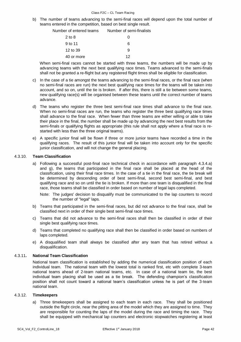
Class F2C – CL Team Racing
SC4_Vol_F2_ControlLine_18 Effective 1st January 2018 Page 42
b) The number of teams advancing to the semi-final races will depend upon the total number of
teams entered in the competition, based on best single result.
Number of entered teams Number of semi-finalists
2 to 8 0
9 to 11 6
12 to 39 9
40 or more 12
When semi-final races cannot be started with three teams, the numbers will be made up by
advancing teams with the next best qualifying race times. Teams advanced to the semi-finals
shall not be granted a re-flight but any registered flight times shall be eligible for classification.
c) In the case of a tie amongst the teams advancing to the semi-final races, or the final race (when
no semi-final races are run) the next best qualifying race times for the teams will be taken into
account, and so on, until the tie is broken. If after this, there is still a tie between some teams,
new qualifying race(s) will be organised between these teams until the correct number of teams
advance.
d) The teams who register the three best semi-final race times shall advance to the final race.
When no semi-final races are run, the teams who register the three best qualifying race times
shall advance to the final race. When fewer than three teams are either willing or able to take
their place in the final, the number shall be made up by advancing the next best results from the
semi-finals or qualifying flights as appropriate (this rule shall not apply where a final race is re-
started with less than the three original teams).
e) A specific junior final will be flown if three or more junior teams have recorded a time in the
qualifying races. The result of this junior final will be taken into account only for the specific
junior classification, and will not change the general placing.
4.3.10. Team Classification
a) Following a successful post-final race technical check in accordance with paragraph 4.3.4.a)
and g), the teams that participated in the final race shall be placed at the head of the
classification, using their final race times. In the case of a tie in the final race, the tie break will
be determined by descending order of best semi-final, second best semi-final, and best
qualifying race and so on until the tie is broken. If more than one team is disqualified in the final
race, those teams shall be classified in order based on number of legal laps completed.
Note: The judges' decision to disqualify must be communicated to the lap counters to record
the number of "legal" laps.
b) Teams that participated in the semi-final races, but did not advance to the final race, shall be
classified next in order of their single best semi-final race times.
c) Teams that did not advance to the semi-final races shall then be classified in order of their
single best qualifying race times.
d) Teams that completed no qualifying race shall then be classified in order based on numbers of
laps completed.
e) A disqualified team shall always be classified after any team that has retired without a
disqualification.
4.3.11. National Team Classification
National team classification is established by adding the numerical classification position of each
individual team. The national team with the lowest total is ranked first, etc with complete 3-team
national teams ahead of 2-team national teams, etc. In case of a national team tie, the best
individual team placing shall be used as a tie break. The defending champion’s classification
position shall not count toward a national team’s classification unless he is part of the 3-team
national team.
4.3.12. Timekeepers
a) Three timekeepers shall be assigned to each team in each race. They shall be positioned
outside the flight circle, near the pitting area of the model which they are assigned to time. They
are responsible for counting the laps of the model during the race and timing the race. They
shall be equipped with mechanical lap counters and electronic stopwatches registering at least

Class F2C – CL Team Racing
SC4_Vol_F2_ControlLine_18 Effective 1st January 2018 Page 43
1/100th second, with a minimum timing limit of 15 minutes. The stopwatches may be replaced
or complemented by a computerised timing system of equal or better accuracy.
b) The time for the flight shall be calculated as defined below:
i) If all three watches record a time, a maximum tolerance of 0.18 seconds is allowed
between the middle watch time and each of the two other watch times (lower and higher
ones). If all recorded times are within the defined tolerance, the time for the flight shall
be the average of the three watch times.
ii) If one stopwatch differs from the closer of the other two by more than 0.18 seconds, then
the average time shall be calculated from the other two watch times.
iii) If both the lower and upper recorded times exceed the tolerance, the team shall be given
the choice between having a re-flight or accepting the middle time as the time for the
flight. Once the team has made its choice, the decision is irreversible.
iv) If only two watches record a time and they are within the 0.18 second tolerance, the time
for the flight shall be the average of the two watch times.
v) If only two watches have a time and they are not within the 0.18 second tolerance, the
team shall be notified. The team may accept the higher of the two watch times or be
granted a re-flight. Once the team has made its choice, the decision is irreversible.
vi) If only one watch has a time, the team shall be notified. The team may accept the single
time or be granted a re-flight. Once the team has made its choice, the decision is
irreversible.
vii) If all watches fail, there will be no recorded time, the team shall be notified and granted a
re-flight.
viii) The time retained will be made up to the next upper 1/10th second.
ix) All decisions about timing must be reported to the F2C Chief Judge without delay.
4.3.13. F2C Panel of Judges
a) The contest organisers shall appoint three Judges, from the list of CIAM-approved judges
proposed by the National Air Sport Controls. Each Judge shall have had proven proficiency and
recent experience in international competition and judging at that contest’s standard. The
Judges shall have a working understanding of a common language.
At World and Continental Championships, and other limited entry international competitions, the
Judges shall be of different nationalities.
In open international competitions, the Judges shall be of at least two nationalities and two of
them shall be from the list of CIAM-approved judges.
b) The Judges are responsible for observing the conduct of each team during each race.
c) Notice of warnings and disqualification are given by loudspeaker announcement and coloured
lights:
Green light - First warning (first offence)
Amber light - Second warning (renewal of the first offence or a new offence)
Red light - Third warning (renewal of previous offences or a new offence) and
disqualification (in qualifying and semi-final races).
For the final only, a team shall be disqualified after a fourth offence, (renewal of previous
offences or a new offence) by the judges verbally announcing “(Team Colour) - fourth
offence, disqualified”.
In addition, a second set of lights, corresponding to the team colours, shall be provided.
Upon the announcement of the fourth warning in a final race, the appropriate light for the
disqualified team shall be displayed.
Note: The Team Race Judges’ Guide is at Annex 4C.

SC4_Vol_F2_ControlLine_18 Effective 1st January 2018 Page 44
PAGE DELIBERATELY LEFT BLANK

Class F2D CL Combat
SC4_Vol_F2_ControlLine_18 Effective 1st January 2018 Page 45
4.4. CLASS F2D – CL COMBAT
4.4.1. Definition of a Combat Event
A combat event is a contest during which eliminating heats are followed by a final in which two competitors with their model aircraft fly in the same circle at the same moment for a predetermined time, the object being to cut a streamer attached on the longitudinal centre line of the opponent's model aircraft, points being awarded for each cut taken.
4.4.2. Definition of a Combat Model Aircraft
a) Model aircraft in which the propulsion energy is provided by a piston motor(s) and in which lift is obtained by aerodynamic forces acting on surfaces which remain fixed in flight, except for control surfaces.
b) The longitudinal centre line shall be defined as the axis of the propeller in case of a single engined model aircraft and the axis of symmetry in the case of multi-engine model aircraft.
4.4.3. Combat Site
A combat site must consist of three concentric circles which shall be marked on the ground.
a) The pilot circle: radius 2 metres.
b) The flight circle: radius 20 metres.
c) The pitting circle: radius 22 metres.
The flight and pitting circles must be laid out on grass. The pilot circle may be laid out on grass or any other material. The area between the 20 and 22 metre circles is called the pitting area.
During active combat periods the pilot and his mechanic(s), officials, team managers and others within the boundary of the designated combat flying area must wear a safety helmet, with a fastened chinstrap, strong enough to withstand the impact of a flying combat model aircraft.
To avoid the catching of the opponent’s lines the protruding parts of the helmet must be covered. No communication using electronic devices is allowed between the pilot and mechanics/persons outside.
4.4.4. Competitor
The pilot, who shall be the entrant and known as the competitor, may employ a maximum of two mechanics in any one heat. (In exceptional circumstances of wet or extremely windy weather, an additional helper may be used as a streamer holder and must perform no other function for the duration of that combat period).
For World and Continental Championships, the mechanics (helpers), a maximum of six other than team members or the team manager (or assistant team manager), must be registered for no more than one national team, from the beginning of the competition throughout to the end.
For Category 1 competitions F2D Mechanics must hold a valid sporting licence.
4.4.5. Characteristics
a) Maximum loading: 100 g/dm2
Maximum swept volume of motor(s): 2.5 cm3
b) Line length: 15.92 +/- 0.04 m
Minimum line diameter: 0.385 mm (no minus tolerance)
Two multi-strand control lines must be used. No free ends capable of entangling an opponent's lines, and no line splices, are permitted. Open connection connectors are not allowed.
c) Engines with glow plug ignition shall have their exhaust port(s) connected to silencer(s) (one or two), consisting of a simple chamber with one circular cross-section, rearmost outlet aperture of 6 mm diameter (1) or 4.2 mm diameter (2) opposing the exhaust port connection.
The minimum total volume of the exhaust system shall be 12.5 cm3. In the case of two exhausts, each silencer shall have a minimum volume of 6 cm3.
The maximum total length of the exhaust system from exhaust port(s) of the cylinder to and including outlet(s) is 15 cm. One pressure tap directly connected to the fuel tank, of 2 mm maximum diameter is allowed. No other openings or vents are allowed.
cont/…

Class F2D CL Combat
SC4_Vol_F2_ControlLine_18 Effective 1st January 2018 Page 46
d) The motor shall be naturally aspirated via a single round venturi with a maximum effective diameter of 4 mm.
e) Any interconnecting chamber between the air intake and the induction port of the motor shall have a maximum volume of 1.75 cm3. This clearly prohibits sub-piston induction for supplementary air intake.
f) A safety wire with a minimum diameter of 0.5 mm must be attached between the control system and the engine(s). The engine(s) must always stay connected to the lines.
g) A safety strap connecting the competitor's wrist to the control handle must be provided by the competitor and worn at all times while his model aircraft is flying. The strap should be as shown in the sketch i.e. it should be attached to the wrist with a loop and sliding knot so that if the handle is released it will tighten itself securely around the wrist. The point of attachment at the handle is up to the discretion of the pilot.
h) The model aircraft shall not carry any artificial aid to assist the cutting of the streamers.
i) The model aircraft shall be equipped with a device (referred to as the “streamer hook”), specially designed to retain the streamer which shall be fitted on the longitudinal centre line and sufficiently strong so that the streamer does not become detached under normal flying conditions.
j) Standard fuel shall be supplied by the organisers to the following formula: 10% nitromethane 20% castor oil lubricant (first pressing) 70% methanol. Fuel shall be mixed by volume.
Note: Fuel for compression ignition engines is not restricted.
k) Each model aircraft must be equipped with an engine shut-off device that stops the engine automatically if a fly-away occurs. The shut-off can be inactive at take-off, as long as it becomes active before combat starts. Once active, the device must remain functional for the entire time the model aircraft remains airborne. The device may only be used to stop the engine.
Note: CIAM General Rule B.1.2.2 does not apply to engine-stop devices in class F2D as the device may be electronic and controlled via the lines or wireless.
4.4.6. Technical Verification
To be tested before each heat:
a) Each set of lines must be checked for length and diameter.
The line length is measured from the inboard face of the grip of control handle to the longitudinal centre line of the model aircraft.
A pull test shall be applied to the assembled handle(s), control lines and model aircraft. The pull test shall be equal to 20 kgf.
The processing officials or judges may ask the competitor to change the lines if there is any doubt about the line quality, such as kinks, curls, stress or rubbing marks.
b) The intake opening shall be checked with a simple plug gauge (diameter 4.05 mm) per the following sketch:
Safety strap withslipknot
Control Handle
HANDLE & SAFETY STRAP FIGURE

Class F2D CL Combat
SC4_Vol_F2_ControlLine_18 Effective 1st January 2018 Page 47
c) The outlet of the silencer(s) shall be checked with a simple plug gauge (diameter 6.05 mm for one silencer and 4.25 mm for two silencers) per the following sketch:
d) Demonstration of the engine shut-off device may be required by the judges before each heat.
Additional demonstrations may be requested by the judges after the heat.
e) The safety strap(s) and safety wire(s) may be pull tested with a load equal to 20 kgf.
4.4.7. Number of Model Aircraft
a) Only one model aircraft specification certificate is required for each design of model aircraft presented by each competitor.
b) Each competitor shall be permitted a maximum of two model aircraft, two handles, two pairs of lines and two engines in each combat heat. If the reserve model aircraft is used, the streamer or its remaining parts must be transferred to the reserve model aircraft. The handle plus lines for the reserve model aircraft must be placed just outside the pilot circle.
c) Engines, control lines or handles may not be replaced or interchanged during the combat period.
4.4.8 Streamer
The streamer shall consist of double weight crepe paper (80 g/m2) or any replacement of equivalent strength, not less than 3 m nor more than 3,5 m long and 3 +/- 0.5 cm wide, fixed to a sisal (or any replacement of equivalent strength) string of 2,75 m minimum length.
All streamers must be of the same length.
There shall be a clearly visible ink mark 2 m from the junction of the string and streamer.
The streamer shall be attached to the model aircraft in such a way that the ink mark is level with, or behind, the rearmost portion of the model aircraft (see sketch). The attachment part of the string shall have a minimum length of 0,75 m.
The attachment end of the streamer shall be reinforced on either side by tape approximately 2 cm wide affixed diagonally to the length of the streamer with one at right angles to the other and extending for a maximum of 5 cm. An additional fibre/fabric reinforced tape 2 cm wide is affixed across the streamer (see detail below).
cont/…
Class F2D CL Combat
SC4_Vol_F2_ControlLine_18 Effective 1st January 2018 Page 48
The colour of the streamer must be different for the two competitors in the heat. Each pilot/pit crew shall be issued with a streamer at the start of the heat by the judge assigned to that competitor. A second streamer will be available from this judge when needed.
4.4.9. The Heat from Start to Finish
a) All signals shall be both acoustic and visual.
b) During the starting period the launching positions must be separated by at least a quarter of a lap. The first named competitor in the draw shall have the choice of streamer colour and the other the choice of starting position
c) It is the responsibility of the pilot/mechanics to make sure the streamer is unrolled before take-off.
d) The motor(s) must be started by flicking the propeller by hand.
e) A first signal, given by the Official Timer, shall signify the beginning of the 30 seconds period when the mechanic(s) or the pilot have the opportunity to start, run and adjust their motors.
f) A second signal, given by the Official Timer, shall signify the beginning of the combat heat period on or after which the model aircraft may be launched.
g) From the moment the Official Timer has given the signal to launch, the combat heat lasts for a maximum of 4 minutes.
h) When the Circle Marshal is satisfied that each model aircraft has completed two level laps, anti-clockwise, separated by approximately half a lap, he will give a signal that combat may begin.
i) Following an interruption when one or both model aircraft have been grounded, combat may restart after a signal from the Circle Marshal. This signal shall be given as soon as the Circle Marshal is satisfied that there is approximately half a lap separation between the two model aircraft.
j) If, after a mid-air collision, no streamer can be found and the streamer retaining device is missing or bent, then, with the permission of the judges, it is acceptable to continue the heat without replacing the streamer.
k) Only the streamer/string may be moved around the circle by the mechanics/pilot. Models in the pitting area may not be moved, other than to maintain a safe distance of approximately 5 metres from the opponent’s mechanics. Under conditions of heavy wind, the Judges can allow models with a non-running engine to be moved to a safer starting position.
l) When moving around the circle the mechanics/pilots must be on the outside of the pitting circle. Within the flight circle, mechanics may only move radially inward and outward. Within a pit crew/team’s pitting area they are free to move around and also to choose where to enter and step out of the pitting circle.
m) If, as a result of a mid-air collision, the silencer is detached and the model aircraft remains airborne, the heat may continue. After a landing, however, the silencer must be replaced before the model aircraft can be used again.
n) The Circle Marshal will monitor the conduct of both pilots, and shall issue a yellow card warning to any pilot who uses a rough or unsafe flying style, causes line tangles, or displays unsportsmanlike behaviour. Each yellow card issued (a maximum of three for each pilot, per competition) shall be officially recorded and retained for the remainder of the competition. Initial and subsequent offences during a competition are to be penalised in accordance with 4.4.12A and 4.4.12C, respectively. If the first yellow card incident is considered severe, the pilot shall also be disqualified for the offence.
Note: Yellow cards are cumulative throughout the competition. 1st yellow card = 40 point penalty
or disqualification from the heat for a more serious offence. 2nd yellow card = disqualification from the heat. 3rd yellow card = disqualification from the heat.
o) The Circle Marshal shall give an acoustic signal to terminate the combat heat:
i) 4 minutes after the signal to launch (10 seconds countdown).
ii) if both streamer strings have been cut and the pilots have been asked to fly level and anticlockwise, and to cease combat (10 seconds countdown).
iii) if one pilot has only the string remaining and requests to cease combat the Circle Marshal should instruct both pilots to fly level and anti-clockwise (10 seconds countdown).
cont/…

Class F2D CL Combat
SC4_Vol_F2_ControlLine_18 Effective 1st January 2018 Page 49
iv) if the heat has to be terminated due to disqualification of one or both competitors or for any other reason.
The pilot(s) must stop their motor(s) and land after the heat is terminated.
p) In the case of a fly away (where the shut-off works), the mechanic can choose to leave the model where it landed and just collect the streamer.
4.4.10. Scoring
a) Scoring shall start at the signal to launch and continue during the heat (maximum 4 minutes).
b) 100 points shall be awarded for each distinct cut of the opponent's streamer. There is a cut each time the model aircraft, propeller or lines etc fly through the opponent's streamer resulting in particle(s) becoming detached from the streamer. A cut that contains only string does not count.
c) Two points shall be awarded for each second that a model aircraft is airborne during the heat.
d) Each penalty point given (See 4.4.12) shall be subtracted from the competitor’s score.
e) In the event of a tie score in any heat, that heat shall be re-flown. A heat is considered a tie if the score difference is 10 points or less.
4.4.11. Reflights
A reflight may be granted:
a) In the event of a line tangle and only one model aircraft being grounded, making it impossible to clear the line tangle.
b) If, as a result of combat, a model aircraft cuts its own streamer/string or the streamer/string becomes wrapped around the model aircraft and/or the lines (unless only string remains).
c) at the discretion of the Judges/Circle Marshal if an unfair or unsafe situation occurs and none of the pilots/mechanics can be blamed.
If flying, the pilot(s) must stop their motor(s) and land after the decision of a reflight.
4.4.12. Penalties and Disqualifications
A. A competitor will receive a penalty of 40 points:
a) If he steps outside the pilot circle with one foot while his model aircraft is airborne.
b) If the mechanics enter the flying circle at an oblique angle or cut across the flying circle to reach a downed model aircraft or run around the circle within the pitting area, one penalty only will be given for each offence even if more than one mechanic is involved.
c) If the mechanic(s)/pilot do not immediately, or after a clearing a line tangle, withdraw a grounded model aircraft to the pitting area prior to servicing it. It is not allowed to service the model or remove the streamer until any line tangle is cleared.
d) If the model aircraft is launched prior to the starting signal.
e) If the mechanic(s)/pilot allows both engines to be running at the same time during the flight period.
Brief bursts, not longer than 10 seconds to warm the engine with a prime or to clear a flood is permitted. Running the engine from the tank is not permitted.
f) When he receives his first yellow card (Subject to 4.4.9.n.).
B. A competitor will receive a penalty of 100 points:
a) If the streamer does not cleanly unfurl upon launching the model aircraft.
b) If the mechanic(s) damage the streamer or allow the model aircraft to cut its own streamer whilst still on the ground, and launch the model without replacing the streamer.
c) If the string (with or without the streamer) becomes detached from the model aircraft while airborne but not as the result of a mid-air collision.
d) If the silencer falls off during the flight or ceases to operate.
In all these cases the pilot, on a signal from a Judge, must immediately land and unfurl the streamer or replace the streamer or replace the silencer. The watches should be stopped at the moment the model lands. The Judges will measure and deduct the time between the decision to land and when the model lands.
cont/…
Class F2D CL Combat
SC4_Vol_F2_ControlLine_18 Effective 1st January 2018 Page 50
C. A competitor will be disqualified from the heat:
a) If he flies with a model that does not conform to 4.4.5.
b) If his model aircraft fails to become airborne within two minutes of the signal to launch.
c) If he attempts to fly a model aircraft which at the time of launch does not have a:
i) strong effective control mechanism;
ii) secure engine attachment
d) If he deliberately attacks the streamer of his opponent's model aircraft prior to the Circle Marshal’s signal to start combat.
e) If he interferes with his opponent, or forces his opponent to leave the pilot circle.
f) If, while his model is not airborne and his opponent is flying or ready to fly, he leaves any parts of his model or lines in the pilot circle without an immediate attempt to clear them.
g) If he attacks his opponent's streamer without his own, or the remaining parts, attached to his model aircraft (Except for 4.4.9.j).
h) If he is not present at his allotted flight time, unless he has the express permission of the Event Director.
i) If he steps out of the pilot circle with both feet while his model aircraft is flying.
j) If he leaves the pilot circle without informing his opponent of his intention to do so when his model aircraft is grounded for a purpose other than to pick up the lines of the reserve model aircraft or to allow his model aircraft to be serviced.
k) If he flies in such a manner as to inhibit his opponent, or his opponent's pit crew, from clearing any line tangle.
l) If he flies other than level in an anti-clockwise direction when only his model aircraft is airborne and there is no line tangle. Sudden or rough manoeuvres are not allowed.
m) If he fails to clear any line tangle prior to launching his reserve model aircraft unless both he and his opponent have informed the Circle Marshal that they have agreed to continue the heat without clearing the line tangle. In this event the Circle Marshal must agree to the continuation, only doing so when he is satisfied that it is safe to continue.
n) If he releases the handle and the safety strap separates from the handle or wrist or he removes the safety strap, for any reason, while the model aircraft is flying.
o) If he interferes to cause a ground hit of, or collides with, his opponent's model aircraft that clearly has no streamer left and flies level in anticlockwise direction without any manoeuvres to chase and attack.
p) If his mechanic(s) enters the flying circle while both models are flying, or during a line tangle where at least one of the models remains airborne.
q) If a mechanic jumps over the opponent’s model aircraft and lines kept within the pitting area.
r) If, in the event of a flyaway, his engine shut-off device does not activate.
s) When he receives his second or third yellow card.
t) For any other flagrant breach of the rules.
4.4.13 The use of Video equipment
The Organiser/Judges may use video recording equipment to monitor the pilots and the pilot circle.
At the discretion of the Judges/Circle Marshal the officially recorded video can be used as a judging tool.
4.4.14 Individual and Team Classification
a) The contest shall be run as a knockout tournament.
b) The competitor who obtains the highest score in points shall be the winner of each heat.
c) A competitor shall be eliminated from the competition when he has lost two heats.
d) Each round shall be randomly drawn (subject to 4.4.14.e)) from the competitors remaining in the competition.
cont/…
Class F2D CL Combat
SC4_Vol_F2_ControlLine_18 Effective 1st January 2018 Page 51
e) Previous opponents and competitors of the same nationality shall be drawn apart if possible with competitors of the same nationality to fly against each other only if there are no remaining opponents.
Defending champions, not members of their national team, are considered as individuals not possessing any specific nationality.
f) In a round with an odd number of competitors the non-flying competitor will fly twice in the following round, in the first heat and in the last heat (if the number of competitors permit it and he is still in the contest).
g) Each competitor shall be ranked according to his number of wins, not counting fly-off heats, with the fly-off heats being used to establish second and third place as necessary.
h) In the event of a tie for second or third place, the equal placed flyers shall take part in a fly off, during which they shall be allowed only one loss. In the event of a tie for third place after a fly-off for second place then there shall be a new fly-off for third place.
i) A specific junior final tournament will be organised if juniors are at the same placing (tie) in the general tournament, in order to define who is first, second and third for the specific individual placing and will have no influence on the general individual placing (no change in the team classification).
j) The competitors’ "win" scores, not counting fly-offs, shall be added for the participants of each nation.
k) The team classification is established by taking the total scores, obtained in 4.4.14.g) above, of the three best scoring members of the team and adding them together. In the case of a team tie for any of the top three places, the team with the lower sum of place numbers, given in order from the top, wins. If still equal, the best individual placing decides. Complete three-competitor teams are ranked ahead of two- competitor teams which, in turn, are ranked ahead of single competitor entries.
4.4.15. Judges and Timekeepers
a) The organisers shall appoint a panel of three judges who shall be selected from a list of persons proposed by National Airsport Controls for their proficiency and experience and approved by the CIAM. The judges must have at least one language in common. At World and Continental Championships and other limited entry international competitions, the judges must be of different nationalities. In open international competitions the judges must be of at least two nationalities and only two of them must be approved by CIAM. At World Cup and other Open International Competitions one of the judges and the Circle Marshal can be the same person.
b) Three timekeepers/scorers shall be allocated to each competitor for World and Continental Championships, two for Open Internationals.

SC4_Vol_F2_ControlLine_18 Effective 1st January 2018 Page 52
PAGE DELIBERATELY LEFT BLANK
Annex 4A - Class F2A Judges’ Guide
SC4_Vol_F2_ControlLine_18 Effective 1st January 2018 Page 53
- ANNEX 4A -
CLASS F2A - JUDGES' GUIDE
F2A is, essentially, a simple class to administer with very few rules. However, it is important that there is continuity of interpretation from one Championship to another and it is for this reason that this Judges’ Guide has been written.
Rule 4.1.1. Definition of Speed Model Aircraft
Requires no clarification.
Rule 4.1.2. Characteristics of Speed Model Aircraft
a) When measuring the surface area, allowance should be made for the geometrically projected shape where the wing and tail join the fuselage.
b) Model aircraft must be checked for the fitment of a shutoff.
c) The shutoff must be checked for mechanical function in the line check prior to each attempt.
d) To check shutoff function:
i) Using a squash bottle, fuel must be shown to flow from the fuel tank to the engine.
ii) The shutoff must then be activated and resistance to fuel flow from the fuel tank to the engine using a squash bottle must be felt.
e) The fuel bottle should be of approximately 100 cc capacity and must be fitted with a fuel filter.
Rule 4.1.3. Fuel
a) It should be noted that the lubricant specified is castor oil only.
b) No additives are allowed so only first pressing castor oil may be used.
c) Proprietary brands such as Castrol M which may contain additives may not be used. This is essential to maintain standardisation of fuel supply throughout the world.
d) The fuel mix ratio should be measured by volume and mixed thoroughly.
e) The fuel mix should be tested for methanol/oil ratio by testing its specific gravity using a standard calibrated float.
f) The fuel mix must be verified by the FAI Jury.
Rule 4.1.4. Diameter of Control Lines
a) This rule should cause no problem but plated wire is not permitted under rule 4.1.4. which states that “no coating material may be applied to the lines”.
b) A micrometer, as detailed in 8.1.1 of Annex 4F Control Line Organiser’s Guide, must be supplied and used by the contest organisers to measure the control line wires.
Rule 4.1.5. Length of Course
a) The measured distance covered by the model aircraft must be at least one kilometre.
b) The radius of the flight circle must be 17.69 m (9 laps = 1 km).
Rule 4.1.6. Line Test
a) The pull test must be applied to the handle grip NOT the horizontal cross bar.
b) The pull test on the wrist strap is to test the strength of the strap and its attachment to the handle. It is not to test the strength of the control system.
Rule 4.1.7 Control Handle and Pylon Fork
a) This rule states that “the horizontal cross bar must be in continuous contact with the pylon fork during the official flight”.
b) This statement does not mean that the cross bar must be behind the fork and above the “V” piece as illustrated in the sketch.
c) The important factor is that the cross bar stays in contact with both of the fork prongs throughout the flight.
d) The cross bar may be above or below the “V” or one end of the cross bar may be in front of the fork.
e) Any position other than that illustrated in the sketch makes it more difficult for the pilot and he will therefore always strive to achieve that position.
f) The “V” is there only to assist the pilot achieve the preferred position. There is no speed advantage to be obtained from any other position. The pilot cannot see the pylon and it could be disastrous for him to look to check the position.
g) It is recommended that the locking of the pylon height should be by a clamping mechanism which allows for unlimited adjustment and not by pre-set increments.

Annex 4A - Class F2A Judges’ Guide
SC4_Vol_F2_ControlLine_18 Effective 1st January 2018 Page 54
Rule 4.1.8. Definition of an Attempt
a) The competitor has 3 (three) minutes from the starting signal to take off and place his handle in the pylon.
b) The timing sequence will then take place. Thus the timing of the official flight may start and finish more than the 3 (three) minutes after the time of the starting signal.
Rule 4.1.9. Number of Attempts
Competitors may not take their second attempt without first returning to the line check area in order to comply with rules 4.1.3. and 4.1.6.
Draw for Flying Order
a) It is recommended that the draw should be arranged so that competitors fly at five minute intervals.
b) The draw should be arranged so that competitors from one nation are not required to fly within fifteen minutes of each other.
c) After the draw has taken place, it should be split into three equal groups, A, B and C.
d) For round one, group A flies first, followed by group B and then group C.
e) For round two, group B flies first, followed by group C and then group A.
f) For round three, group C flies first, followed by group A and then group B.
g) For round four competitors will fly in the reverse order of position after round three, up to position four. The competitors in first, second and third places after round three then fly in sequential order, first, second, third.
h) There should be a ten minute break at the end of each hour of flying.
i) Re-flights (second attempts) should take place at the end of each round.
j) Replacement attempts may take place at the end of the group in which the attempt was scheduled, or in the scheduled ten minute break at the end of each hour of flying
k) Replacement attempts and second attempts shall be taken in the original draw order.
Rule 4.1.10. Definition of an Official Flight
An audible signal should be made to the pilot at the end of the timed flight by one of the timekeepers.
Rule 4.1.11. Number of Flights
Requires no clarification.
Rule 4.1.12. Number of Helpers
• Care must be taken to ensure that this rule is complied with.
• In addition to the two helpers, the team manager may enter the contest circle. When this is the case he may not assist the pilot or helpers, but he is permitted to carry and hold any equipment which the pilot and helpers require to use.
• In the case of an incomplete team, only speed team members of other incomplete teams or supporters or competitors from other control line classes may be registered to act as helpers.
• They can help only one team.
• Except for incomplete teams, competitors may not act as helpers for competitors from other nations
Rule 4.1.13. Start of Timing
a) The chief timekeeper should determine when the pilot has placed his handle in the pylon - NOT the judge who is observing the conduct of the pilot.
b) The chief timekeeper must call when the pilot has placed his handle in the pylon.
c) For manual timekeeping, he will call “two” when, after the pilot has placed his handle in the pylon, the model aircraft first passes the height marker. He will then call “one” as the model aircraft again passes the height marker.
d) The timekeepers start timing the next time the model aircraft passes the height marker.
e) The timekeepers should preferably be positioned one behind the other, not side by side.
f) When an electronic timing system is used, the chief timekeeper will initiate the primary timing device when he observes that the pilot has placed his handle in the pylon. As he does so he will call “in” and the backup timekeeper will immediately initiate the backup system.
g) The judge who is observing the pilot must call if the pilot removes the handle from the pylon.
h) The timekeepers and circle judges must use the official practice session to train in their individual and collective duties.
cont/…

Annex 4A - Class F2A Judges’ Guide
SC4_Vol_F2_ControlLine_18 Effective 1st January 2018 Page 55
Rule 4.1.14 Height of Flight
a) Two judges must be used for this task; one for each of the height markers.
b) They must be positioned at eye level to the respective height marks.
c) The height restriction applies only during the timed run.
Rule 4.1.15 Cancellation of Flight
Requires no clarification.
Rule 4.1.16. Number of Timekeepers and Judges
Requires no clarification.
Rule 4.1.17. Classification
Requires no clarification.
Training/Practice
a) The official training/practice session should continue on the draw basis as currently used where each competitor is allocated a ten minute slot.
b) The circle should not be available for practice during the round (allowing practice at, say, lunchtime can give unfair advantage to competitors drawn to fly after lunch).
c) Practice on free days and after the rounds should not be on a draw basis.
d) Speed competitors have learned to self-regulate circle use by each taking one flight in rotation. This system allows many more practice flights per hour than any draw based practice session. All competitors then have a chance to make a test flight, go away and make adjustments, think about what is required and return for another test.

SC4_Vol_F2_ControlLine_18 Effective 1st January 2018 Page 56
PAGE DELIBERATELY LEFT BLANK
Annex 4B - Class F2B Judges’ Guide
SC4_Vol_F2_ControlLine_18 Effective 1st January 2018 Page 57
- ANNEX 4B -
CLASS F2B - JUDGES' GUIDE
4.B.1. Purpose
This Judges’ Guide is an aid to judging and marking FAI class F2B contests. It should be used both for the training of potential F2B judges and for maintaining the proficiency of judges who are already judging at F2B contests. This Judges’ Guide forms an integral part of the FAI Sporting Code Section IV Volume F2 applicable to class F2B.
4.B.2. Judges' Qualifications and Selection of Judges for Contests
The National Aero Club (NAC) of each country having F2B judges who join (or who wish to join) judging panels at international F2B contests should ensure that a defined standard of judging proficiency is reached and maintained by each of the judges for which it has responsibility. Each such NAC should therefore:
a) Provide translations into their own language of both the current FAI Sporting Code Volume F2 applicable to F2B (that is the whole of paragraph 4.2) and of this complete Judges’ Guide.
b) Arrange suitable means and procedures to ensure that each judge is fully trained. This means arranging training courses which include regular and repeated group training in both theoretical (classroom) and practical (flight) venues where every aspect of both the current Sporting Code and of this Judges’ Guide may be examined and practised in detail.
c) Provide suitable means for officially recording each such training session attended by every judge within its national responsibility. Such official record should include dates, duration, and number of flights observed at such training sessions, and should also separately list details of all the national and international F2B contests at which each judge has been a member of the judging panel.
d) Establish selection criteria which clearly define the minimum periods of undergoing such training and of actually judging high quality F2B flights at national level before prospective judges are eligible to be nominated or invited to join judging panels at international F2B contests.
Providing all the above will ensure that the judging of all international F2B contests is carried out to the same basic standard. These measures will also enable the organisers of international contests to be sure that all judges invited or nominated to a judging panel do indeed meet the required standards of qualification and experience. The organisers of all World and Continental Championships should therefore submit a list of proposed judges’ names, together with their NAC qualification details as at paragraph c) above, to their own NAC and to the F2 Subcommittee of the CIAM.
To ensure a continuous pool of suitably qualified international F2B judges it is also recommended that, with suitable modifications, each NAC apply the criteria and procedures at the above paragraphs a) through d) inclusive to the selection and training of F2B judges for contests at national level.
4.B.3. Sporting Code and F2B Manoeuvres Knowledge
The primary requirements for fair, accurate, and consistent judging are:
a) A clear understanding of all of the applicable regulations and definitions within the complete Section IV of the FAI Sporting Code.
b) An in-depth and fully detailed knowledge of all the current F2B rules and manoeuvres descriptions.
c) A fully detailed knowledge of this complete Judges’ Guide.
Self-study of all of the above points is a must, as is regular detailed group training at both classroom and flight venues. Such training should cover the practical application of all of the above points to the judging of high quality F2B contest flights. It is stressed here that individual "interpretation" of the intent and/or meaning of the F2B manoeuvre descriptions and rules is strongly discouraged - the purpose of this Judges’ Guide and of the new rules is to eliminate any need for such "interpretation" by individuals.
cont/…
Annex 4B - Class F2B Judges’ Guide
SC4_Vol_F2_ControlLine_18 Effective 1st January 2018 Page 58
4.B.4. Judging Focus
In order to get a complete picture of each manoeuvre, judges should focus their attention on four major aspects:
a) Shape
This is the form or outline of the entire manoeuvre, but shape also relates to the position of each of the figures making up a complete manoeuvre. In manoeuvres consisting of repeated multiple figures (for example, the three consecutive inside loops), an important criterion is that the shape of each individual loop figure is consistently the same for each repetition, and that consecutive manoeuvres should be performed with the second and subsequent manoeuvres all positioned in exactly the same place as the first (superimposed). All manoeuvres should be of the shape defined in the various manoeuvre rules - that is round loops should be round with no flat spots; square manoeuvres should have clearly defined corners connected by “straight line” flight paths (refer to paragraph 4.2.15.1 of the F2B rules).
b) Size
Manoeuvre sizes are often defined in the manoeuvre descriptions by specifying line elevation angle (in degrees of arc above the normal 1.5 metres upright level flight height). Judges should watch for manoeuvres being flown with their tops above or below the specified 45 degrees, 42 degrees, and 90 degrees line elevation angles - and as a result of such errors, judges should therefore watch for complete figures which are either larger or smaller than specified in the respective rule. All such errors should be downgraded in the marks awarded by judges. The use of visible fixed terrain reference points at each site to help judges ”fix into memory” both the 1.5 metres normal upright and inverted level flight height, and 45 degrees lateral angle (1/8th lap) is recommended. Contest organisers are also encouraged to erect suitable markers at contest sites to assist judges, particularly at sites where suitable natural fixed features are missing. Judges should practice using the available terrain features and any erected markers at each contest site during the judges’ calibration flight sessions held before the start of each particular contest (see also 4.B.15 below).
c) Intersections
The judging (and therefore the marking) of the intersections between the various elements of complex manoeuvres is also made easier if judges use fixed terrain reference marks and/or erected markers to "fix into memory" the visual position of the model when it passes an intersection point for the first time in a manoeuvre. Then, by comparing that "locked-in" point with the position of the model when it comes to the same intersection point at later stages of the same manoeuvre, judges will be more easily able to gauge the degree to which the pilot has met the intersection. As already noted, the erection of suitable markers is encouraged to assist in this practice at sites which lack suitable fixed terrain reference points (see also 4.B.15).
d) Bottoms
Normal upright level flight and inverted level flight is specified in the manoeuvre descriptions as being required to be flown at a height 1.5 metres with an allowed tolerance of plus/minus 30 cm. These are all clearly described for each manoeuvre and judges should mark accordingly, as per 4.B.7 and 4.B.10 below, plus also paying close attention to the notes about values and tolerances which appear at 4.2.15 of the F2B rules.
4.B.5. General Comments on the Marking of Manoeuvres
Although control line model aircraft actually fly on the surface of a hemisphere, when seen from the pilot's position, all manoeuvres are flown in two dimensional plane geometry. In other words, because all points on the surface of the hemisphere are at an equal distance from the pilot (that distance is the length of the lines), the pilot sees all manoeuvres as if they were drawn on a flat sheet of paper. But from their position outside the circle, the judges are not in the ideal position to view manoeuvres. Therefore the judges’ marking tasks include a large element of personal analysis and situational awareness that must take their own (less than ideal) viewing position into consideration when awarding marks. There are however a number of precise definitions and values within the manoeuvre descriptions which judges must assess accurately if they are to award fair and consistent marks. These are:
a) Recognition of level flight altitude of 1.5 metres, plus/minus 30 cm.
b) Recognition of height by judging 45 degrees line elevation angle.
c) Recognition of height by judging 42 degrees line elevation angle.
cont/…

Annex 4B - Class F2B Judges’ Guide
SC4_Vol_F2_ControlLine_18 Effective 1st January 2018 Page 59
d) Recognition of a position directly overhead the centre of the flight circle (that is above the centre of the pilot's body and head if he is standing erect).
e) Recognition of "vertical" climbing and diving flight paths (perpendicular to the ground).
f) Recognition of “horizontal” flight paths (parallel to the ground).
g) Recognition of "maximum 2.1 metres radius" as an abrupt change of direction with the resulting requirement for the model to fly the tightest (sharpest) possible corner (see also 4.B.8).
h) Recognition of the correct "Start" and "Stop" points specified in the F2B rules for each manoeuvre (as highlighted within each manoeuvre description by the paragraphs a)"Start of manoeuvre:" and x) "End of manoeuvre").
i) Recognition of the fact that all the above values are specified as seen and measured from the pilot’s viewing point, so judges must make due allowance for models of different sizes, flown on different length lines, and for the difference between the pilot’s position and the judges’ viewing position/s.
j) Judges should also note the requirements of rule 4.2.11a) which not only limits the amount by which judges shall move their original position (to account for changes in wind direction) during a single official flight (+/-1/8 lap), but which also limits the times at which such moves may be made.
4.B.6. Judging Objective Errors
The systematic deduction of points will provide the most uniformity in of standards in judging F2B contests. This system can be applied to all manoeuvres in the following way:
a) Taking normal level flight as an example, judges are expected to award maximum points provided that the model remains inside the values and tolerances defined in the rules throughout all of the judged laps, and provided that it tracks smoothly without any visible height changes (that is: with no jerking or abrupt changes in height or attitude throughout the manoeuvre).
b) But a level flight track which slightly exceeds the stated tolerance (for example, flying 40 cm off the flight track when plus/minus 30 cm is required by the rule) should be considered as a "minor" error. Such a minor error would probably cause the judge to award a mark downgraded by perhaps 0,5 to 1 point.
c) But if a level flight track was off the defined flight track by as much as twice the defined tolerance, this should be considered as a “medium” error, and would probably result in the award of a mark downgraded by 1.0 point or more.
d) And level flight errors of three times the defined tolerance from the defined flight track should be considered as "major" errors, which would probably result in the award of marks downgraded by around 1.5 or 2 points.
In order to use this system successfully, judges must be trained to recognise flight path deviations of 30 cm and 60 cm at a viewing distance of approximately 45 metres. This will require relevant and repeated demonstrations to train judges to be able to readily gauge these measurements. Such training is highly recommended for all judges and this training should also emphasise the various tolerances defined in each manoeuvre description. See also 4.B.9 below.
4.B.7. Judging Subjective Errors
a) “Smoothly”, etc A phrase such as "fly smoothly", is subjective, and the degree to which the model flies smoothly cannot be measured. Similarly, rules statements such as " ... the model should fly two smooth and stable laps ...", are difficult to apply when faced with the task of translating a certain lack of smoothness into an actual mark to be awarded to a contestant. As a basic guide, judges should consider terms such as stability and smoothness to be conditions defined by the absence of "wobbles" or "jerks". Therefore "wobbles" or "jerks" are errors, and each judge should decide on the extent of each such error seen, awarding a downgraded mark according to the severity of each of these errors that he has observed; see also 4.B.10.
b) Turn radii Similarly, judges should recognise that the intent of the manoeuvre descriptions regarding the radius of corners in manoeuvres such as square loop, square eight, triangle, etc, is that models should turn as sharply (tightly) as possible. Therefore, although it is not possible for judges to accurately measure whether a model has or has not made a turn of between 1.5 and 2.1 metres radius, the intent is clearly that models should turn as tightly as possible when making such turns. Therefore judges should award the highest marks to models turning the tightest (sharpest) corners (provided that the required line elevation angles and/or the required model pitch attitude has also been achieved), and they should award the lowest marks to models making the largest (softest) such turns.
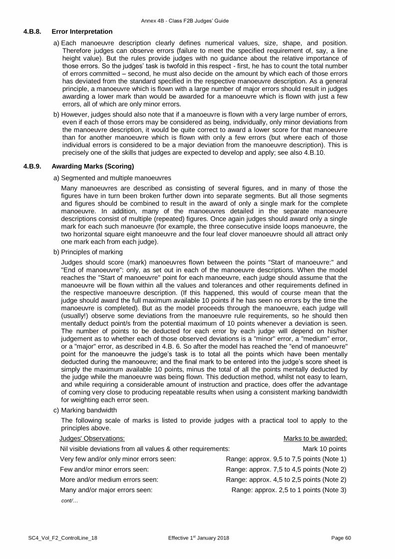
Annex 4B - Class F2B Judges’ Guide
SC4_Vol_F2_ControlLine_18 Effective 1st January 2018 Page 60
4.B.8. Error Interpretation
a) Each manoeuvre description clearly defines numerical values, size, shape, and position. Therefore judges can observe errors (failure to meet the specified requirement of, say, a line height value). But the rules provide judges with no guidance about the relative importance of those errors. So the judges’ task is twofold in this respect - first, he has to count the total number of errors committed – second, he must also decide on the amount by which each of those errors has deviated from the standard specified in the respective manoeuvre description. As a general principle, a manoeuvre which is flown with a large number of major errors should result in judges awarding a lower mark than would be awarded for a manoeuvre which is flown with just a few errors, all of which are only minor errors.
b) However, judges should also note that if a manoeuvre is flown with a very large number of errors, even if each of those errors may be considered as being, individually, only minor deviations from the manoeuvre description, it would be quite correct to award a lower score for that manoeuvre than for another manoeuvre which is flown with only a few errors (but where each of those individual errors is considered to be a major deviation from the manoeuvre description). This is precisely one of the skills that judges are expected to develop and apply; see also 4.B.10.
4.B.9. Awarding Marks (Scoring)
a) Segmented and multiple manoeuvres
Many manoeuvres are described as consisting of several figures, and in many of those the figures have in turn been broken further down into separate segments. But all those segments and figures should be combined to result in the award of only a single mark for the complete manoeuvre. In addition, many of the manoeuvres detailed in the separate manoeuvre descriptions consist of multiple (repeated) figures. Once again judges should award only a single mark for each such manoeuvre (for example, the three consecutive inside loops manoeuvre, the two horizontal square eight manoeuvre and the four leaf clover manoeuvre should all attract only one mark each from each judge).
b) Principles of marking
Judges should score (mark) manoeuvres flown between the points "Start of manoeuvre:" and "End of manoeuvre": only, as set out in each of the manoeuvre descriptions. When the model reaches the "Start of manoeuvre" point for each manoeuvre, each judge should assume that the manoeuvre will be flown within all the values and tolerances and other requirements defined in the respective manoeuvre description. (If this happened, this would of course mean that the judge should award the full maximum available 10 points if he has seen no errors by the time the manoeuvre is completed). But as the model proceeds through the manoeuvre, each judge will (usually!) observe some deviations from the manoeuvre rule requirements, so he should then mentally deduct point/s from the potential maximum of 10 points whenever a deviation is seen. The number of points to be deducted for each error by each judge will depend on his/her judgement as to whether each of those observed deviations is a "minor" error, a "medium" error, or a "major" error, as described in 4.B. 6. So after the model has reached the "end of manoeuvre" point for the manoeuvre the judge’s task is to total all the points which have been mentally deducted during the manoeuvre; and the final mark to be entered into the judge’s score sheet is simply the maximum available 10 points, minus the total of all the points mentally deducted by the judge while the manoeuvre was being flown. This deduction method, whilst not easy to learn, and while requiring a considerable amount of instruction and practice, does offer the advantage of coming very close to producing repeatable results when using a consistent marking bandwidth for weighting each error seen.
c) Marking bandwidth
The following scale of marks is listed to provide judges with a practical tool to apply to the principles above.
Judges' Observations: Marks to be awarded:
Nil visible deviations from all values & other requirements: Mark 10 points
Very few and/or only minor errors seen: Range: approx. 9,5 to 7,5 points (Note 1)
Few and/or minor errors seen: Range: approx. 7,5 to 4,5 points (Note 2)
More and/or medium errors seen: Range: approx. 4,5 to 2,5 points (Note 2)
Many and/or major errors seen: Range: approx. 2,5 to 1 points (Note 3)
cont/…

Annex 4B - Class F2B Judges’ Guide
SC4_Vol_F2_ControlLine_18 Effective 1st January 2018 Page 61
Notes for marking bandwidth table:
Note 1: the number of points actually awarded for each manoeuvre will be dependent upon the total number of errors seen by each judge, and whether or not each judge decides that these are all only minor errors.
Note 2: the number of points actually awarded for each manoeuvre will be dependant upon the total number of errors seen by each judge, and the extent to which each judge decides that each error is either a minor, a medium, or a major error.
Note 3: as per note 2 above, but the mark 0 (zero) points should be reserved only for cases which are listed at 4.2.10 and 4.2.15.2 paragraphs of the F2B rules.
d) Judges should use the entire marks bandwidth available, as shown above. This means awarding a mark of 10 points to any manoeuvre where the judge does not observe any errors at all (for example, an inverted flight manoeuvre where the model remains truly stable and without "jerking" within the allowed height tolerance of plus/minus 30 cm throughout all judged laps). But as an example of the opposite extreme, a two consecutive horizontal square eight manoeuvre which is flown with line elevation angles of over 60 degrees, with "soft" corners, with angled sides, with slanted tops, with pullouts which are both too high and too low, and with intersections which are missed by several metres - in other words a manoeuvre which is not really recognisable at all - should be awarded a mark of around 1 point, perhaps even less.
e) It should also be noted that since nothing written anywhere in the FAI Sporting Code defines terms such as "general impression", or "flying style", accurate and repeatable marking really is dependant only upon each judge deciding on the total number of errors committed, and the degree to which each error has deviated from the manoeuvre description. This includes judging subjective elements where (apart from stability which can be marked as discussed in 4.B.7) the reality is that each contestant's score should depend simply and solely upon the total number of all the errors observed by each judge coupled with each judge's own personal decision as to how severe each of those errors was.
4.B.10. Considering External Factors
a) It is not permitted for judges’ marks to allow for the effects of the wind in marking any phase of any of manoeuvre. Paragraph 4.2.5 of the F2B rules gives clear guidance to judges and contest officials on exactly what wind and weather limitations are not acceptable for official flights, and this means that turbulent or stormy/gusty winds should not influence the marks awarded by the judges unless they exceed the limits in paragraph 4.2.5 of the F2B rules. If wind in excess of the limit in paragraph 4.2.5 does occur then paragraph 4.2.5 also instructs judges and all other contest officials on what actions to take. In other words, either the weather is "flyable" or it’s not, and if it is flyable as per paragraph 4.2.5 then judges should score all official flights on exactly the same basis as if the wind was non-existent.
b) Similarly, electrical storms are considered to be unsafe conditions for flying control line stunt models, and as for excessive wind speed, paragraph 4.2.5 also instructs judges and all other contest officials on what actions to take if thunder and lightning do occur, or appear to be imminent during a contest. Other than excessive wind and electrical storms, the F2B rules make it plain that an F2B contest is an all-weather event, so uncomfortable though it may be for all concerned, the intention is that the contest should proceed as normal. Judges should therefore certainly not adjust their marks according to inclement weather.
c) But on rare occasions other factors which are outside a contestant’s control can occur, and sometimes these could have an affect the contestant’s ability to fly in accordance with the manoeuvre descriptions. For example, when flying contests at sites where one or more grass circles are in use, irregularities in the ground surface could adversely affect a particular contestant’s take-off ground roll and/or lift off; or could affect the ground roll out at completion of the landing manoeuvre. Deviations from the described procedures for the take-off ground roll (and lift-off) or landing ground roll out should not be penalised if judges are of the opinion that such deviations were caused only by defects in the surface of the flight circle. Similarly, paragraph 4.2.7, h) item iii) of the F2B rules gives a possible example (a child or animal wandering into the flight circle), but no set of rules can be expected to be completely comprehensive in such areas. So judges should always be alert for an "extraordinary occurrence" which is both accidental in nature and beyond the control of a contestant, and which could also have an affect on a contestant’s performance of an official flight. If in the opinion of the judges such an incident has occurred then they should be prepared to use their observation and reasoning to make sure (via the Head Judge) that the F2B Contest Director is aware of the occurrence and offers a re-flight accordingly.

Annex 4B - Class F2B Judges’ Guide
SC4_Vol_F2_ControlLine_18 Effective 1st January 2018 Page 62
4.B.11. Scoring and Processing Manoeuvre/s if Missed by a Judge
If a judge misses the observation of a manoeuvre for any reason, then he or she should not mark the Score Sheet with an estimated "typical" mark for the missed manoeuvre. Instead the judge who missed the manoeuvre should clearly write an "N.O." (Not Observed) symbol on his/her score sheet in the space for the mark for the manoeuvre which has been missed. This symbol should then alert the scores tabulator(s) to use a procedure which calculates the average of the marks for that manoeuvre as awarded by all the other judges. This calculated average mark should then be entered into the missing mark ("X") area by the scores tabulator(s) before proceeding with processing all the remaining marks from that flight.
4.B.12. Results Awareness
In order to prevent influence of any kind, no judge should look at tabulated results scores and/or at contestants’ "placing" until after the completion of a contest. Neither should judges discuss individual official flights, nor the execution of manoeuvres; nor the marks awarded, nor the tabulated results (placing) or scores, with anyone at all during the whole contest. This includes discussions with the other judges, with any contestant, with any Team Manager, and with all spectators. The Head Judge should ensure that all members of the judging panel are aware of this requirement and that they all observe these requirements throughout the contest.
4.B.13. Preparations by Judges before Contest Start
Well before the start of any official flights the Head Judge should approach the FAI Jury, the contest organiser and the F2B Contest Director to define/confirm/verify:
a) Head Judge in charge; F2B Contest Director.
b) The availability of fixed terrain reference points, and/or erected markers (refer 4.B.4 b) & c)).
c) Availability and timing of judges’ calibration flights.
d) Contestants' flying order.
e) Contestants' pull test procedure and method of ensuring that all pull tests are performed.
f) Procedure for officially calling contestants.
g) The nominated official timekeeper(s), and how times will be communicated to the judging panel.
h) Availability and method of score sheet collection service.
i) Duration and timing of rounds.
j) Score processing procedures.
k) Contestant and classification and ranking procedures.
l) Meal and break times, seating arrangements, sun shades, umbrellas, nearby toilets, etc.
4.B.14. Judges’ Calibration Flights
After each of the judges’ calibration flights arranged by the contest organiser judges should not discuss the scores that they have individually awarded. Instead they should go through a manoeuvre-by-manoeuvre discussion, comparing and discussing their individual assessments of each error (including the severity of errors) that they have seen during every segment of every figure and every manoeuvre flown. In order to avoid the definitely undesirable "levelling" of marks awarded by each judge, the actual marks (scores) awarded by each judge should not be discussed. Indeed contest organisers are not permitted to issue score sheet forms for judges’ calibration flights. Rather, the judges’ discussions should focus on the number, extent, and degree of severity of each error seen by using copies of the manoeuvre diagrams in the F2B rules as the basis for discussion. It should also be carefully noted that the content of all such judges’ calibration flight discussions should not be made public.
4.B.15. Sighting Devices and Terrain Reference Points
Hand-held sighting devices should not be used. Whenever possible, fixed terrain reference points should be used to define intersections, “verticals”, line elevation angles, and 1/8th lap (45 degrees laterally) bottoms and lengths of manoeuvres and/or segments. As noted at 4.B.4c), contest organisers are strongly encouraged to erect suitable markers (for example for the 45 degrees lateral dimension specified in the relevant manoeuvre descriptions), especially when a particular contest site lacks natural fixed reference points. It is recommended that such reference points and/or markers be re-calibrated for each individual contest site on the occasion of each contest held at that site, and that these should be discussed privately between the judges prior to the start of judges’
Annex 4B - Class F2B Judges’ Guide
SC4_Vol_F2_ControlLine_18 Effective 1st January 2018 Page 63
calibration flights. Final agreement on useable natural reference points and/or erected markers should be reached between all members of the judging panel before the start of official flights.
4.B.16. Timekeeping
It is common practice to assign official timekeeping duties to the Circle Marshall (and this is a definite requirement at World and Continental championships and other limited international contests). At other contests, judges should confirm who is responsible for this task before starting official flights, and at all contests judges should also confirm the method/s by which the results of the official timekeeping will be signalled to the judges. The times recorded by the defined official timekeeper are binding, but as a cross reference it is recommended that the Head Judge runs his own stopwatch in parallel to the official timekeeper. If a contestant’s official flight exceeds the 7 minutes permitted, then the elapsed time should be recorded on the score sheets. In the event of any discrepancy the Head Judge’s time and that of the official timekeeper the Head Judge should approach the official timekeeper and the F2B Contest Director to resolve the matter accordingly.
4.B.17. Consistency
Judges should use a consistent scale of awarding marks throughout all the rounds of a contest. This scale should be a personal instrument based upon the number of errors seen, plus the judge's own personal valuation of the severity of each error. This personal scale should have been arrived at by careful study of the current F2 volume of the FAI Sporting Code (especially paragraph 4.2.15 corresponding to the F2B manoeuvre descriptions), by study of this Judges’ Guide and as a result of practical judging experience. Once the official flights of a contest have started, each judge’s personal scale should remain firm and fixed and should not (for example) become influenced by factors such as discussions with others (including other judges), by the weather, by model speed, by model type, size, colour, or engine sound, or by an awareness of the reputation or results previously achieved by any particular contestant being judged.
4.B.18. Execution of Manoeuvres
a) " ... a minimum of 11/2 laps"
Competitors may choose to fly more than, but may not fly less than, 11/2 laps between each manoeuvre (including the recommended entry and exit procedures, all as set out at paragraph 4.2.14 of the F2B rules). If a new manoeuvre is started after less than 11/2 intervening laps (plus the recommended entry and exit procedures) have been flown then that manoeuvre should be awarded a mark of 0 (zero) point and 0 (zero) point should also be awarded to every other manoeuvre where less than 11/2 laps (plus the recommended entry and exit procedures) are flown between manoeuvres. This is to allow judges enough time to fully consider (and write down) the score for the preceding manoeuvre before the next manoeuvre is started.
b) Judging the height of intervening laps
The height of the laps flown between manoeuvres is purely a recommendation and should therefore not be judged or marked, but it should be noted that the F2B rules (paragraph 4.2.14 c)) specify a height range within which each contestant should fly the intervening laps. This is to ensure that no contestant flies so high that the time taken to complete the intervening laps is too short to allow the judges to record their scores from the previous manoeuvre.
c) Judging attempted manoeuvre(s)
If a contestant makes more than one attempt at any one manoeuvre during an official flight the judges should only mark the first attempt. Any further attempt(s) at the same manoeuvre during the same official flight should not be marked at all. Similarly, if a contestant starts a manoeuvre but obviously does not complete it (for example, due to the motor suddenly losing power, thereby causing the contestant to descend immediately and then fly level laps) the manoeuvre which the contestant failed to complete should receive a mark of zero (0) point.

SC4_Vol_F2_ControlLine_18 Effective 1st January 2018 Page 64
PAGE DELIBERATELY LEFT BLANK

Annex 4C - Class F2C Panel of Judges’ Guide
SC4_Vol_F2_ControlLine_18 Effective 1st January 2018 Page 65
ANNEX 4C CLASS F2C - TEAM RACE PANEL OF JUDGES GUIDE
This Panel of Judges (hereafter ‘Judges’) Guide is intended to guide the Team Race judges and competitors
to produce a fair and enjoyable competition. The guide is a reflection of the current consensus interpretation
of the Sporting Code F2C rules. Suggestions for amendments to Sporting Code rules or this Guide are
welcomed by the F2 Subcommittee and will be considered at the appropriate CIAM Plenary meeting.
4.C.1
TEAM RACE JUDGES
The judges must have a working understanding of a common language to reduce delays and
errors. It is recommended that the common language be the same language used to issue
warnings and disqualification.
4.C.1.1 The duty of the judges is to assure a fair competition between the teams by penalizing any
defined actions which would be an advantage for one or a disadvantage for another team. Where
ever possible the judges should help the teams achieve their best result by discussion outside the
actual racing.
4.C.1.2 The judges responsibilities regarding the conduct of the racing (issue of warnings,
disqualifications and re-flights) begin with the start signal. However, the judges assist the Circle
Marshall by checking that other aspects of the contest are in accordance with the rulebook.
Examples of this are:
a) All mechanics wearing helmets.
b) Correct application of the 90 seconds’ warm-up and 30-second countdown.
c) Competitors’ unauthorised practice in the official circle.
Infringements should be noted, for the Circle Marshall to rectify.
4.C.1.3. The judges should allocate among themselves the specific tasks of warnings operation,
microphone use and record keeping prior to the actual racing. They should also practice working
together when observing the official practice flights and by viewing videos from recent
championships. It is highly recommended that a video recorder to monitor the pilots and the pilot
circle is situated in the Judges tower. This “official” video record is not be used by the judges to
make decisions whilst the race is in progress but may be reviewed at the conclusion of the race to
decide whether re-flights are warranted or to review a formal complaint. After the end of each
round of racing the competitors may be granted access to the “official” video. The purpose of the
“official” video is for:
a) Viewing by the judges and the FAI Jury following a complaint or protest.
(NOTE: The FAI jury is not limited to viewing the official video only when considering
protests).
b) Review by the judges to improve their coordination.
c) Viewing by teams with the judges for a better all-round understanding.
d) Training of other judges in preparation for subsequent championships.
4.C.1.4 It is recommended that the judges adopt the following procedure for the races:
a) Before the start each judge selects one team (preferably, not his nationality) to watch the
start and during pit stops. The specific items to check for are starting the model’s
engine(s) before the start signal; landing model outside the 19.6m radius flight circle;
mechanic retrieving the model from inside the 19.1m radius circle; handle significantly off
ground; etc. A judge’s decision in these cases is unilateral and, without discussion, and
the appropriate penalties must be given. Any single judge making these unilateral
decisions needs to be aware that because the judges are operating from a fixed location it
may not be possible to view each situation equally, therefore he must be certain that he
makes his decision on the grounds of real safety, advantage, disadvantage situations and
not a minor technical infringement that can only be seen by virtue of position.
b) For the remainder of the race all three judges should observe all three pilots and conduct
a running commentary of their behaviour to allow them to agree on infringements quickly.
The judges are also responsible for observing the models in flight should any collisions
occur. Warnings/disqualifications are issued when two judges are in verbal agreement.
c) The judges are responsible for clearly announcing the warnings, disqualification, and re-
flight decisions immediately.

Annex 4C - Class F2C Panel of Judges’ Guide
SC4_Vol_F2_ControlLine_18 Effective 1st January 2018 Page 66
4.C.1.5. Competitors who feel they have not received a fair result are encouraged to initially make a
complaint to the F2C judges, if this is does not satisfactorily resolve the issue then the competitors
have the right to make an official protest.
4.C.1.6. Warnings are effective at the lap or race time when the infringement occurs. Pilots are expected
to acknowledge the warning appropriately. Failure to rapidly correct the infringement will risk an
additional penalty for same offence.
4.C.1.7. Warnings should be given using short standard phrases wherever possible (see Section 4.C.5).
Warnings are issued with reference to the team’s racing colour, not their name, and additional
verbal communication from the judges should be kept to a minimum to prevent pilot distraction.
4.C.1.8 As there can be variations in the actual marking out of the various circles, the Judges shall be
responsible for checking the accuracy of these before the start of the contest. They shall then be
responsible for informing all competitors prior to the beginning of the contest, the definitions of
inside and outside the line that will be applied in that particular competition. In all cases the
definition of “outside/inside the line” shall be the one that encourages the natural progress of the
race without causing a genuine safety, advantage or disadvantage situation. (See pictures in
section 4.C.4.)
4.C.2. STANDARDS OF JUDGING
4.C.2.1. A contest consists of three distinct sections: qualifying heats, semi-finals, and final. Each section
poses unique problems for the judges and competitors.
The judges shall observe the official practice and conduct a briefing for all competitors before the
first qualification heats or semi-finals start, and also before the final, in order to attempt to
maintain an even judging and flying standard through each section of the contest. It is important
that the judges and competitors understand that the first couple of qualification heats have a
significant effect establishing these standards for the rest of the contest. It is very important that
the judges have a unified understanding of their judging standard before the first heat.
Semi-finals are between contestants with very little difference in airspeed and ability. The judges
should aim to keep a similar consistent judging standard as in the qualifying heats but with
additional emphasis on overtaking and blocking infringements.
The final is a unique race in that it is double the distance and takes four warnings to result in
disqualification. A more lenient attitude toward technical infringements (for example :- model
landing just outside the flight circle, model pitted on the line not outside it, mechanic having one
foot slightly inside the flight circle when retrieving his model and the other models being
sufficiently far away as not to cause a safety risk) is warranted but the judges must issue warnings
where safety is at risk and for infringements that provide a team an unfair advantage or
disadvantage (whipping, blocking, taking the centre, etc). When a team with three warnings is
guilty of a further technical infringement that will not materially alter the race result the judges are
urged to announce the infringement but to consider allowing the race to continue unless that team
continues to race in a dangerous, obstructive or advantageous way. It is preferable that the
results are determined by this approach and would allow a team to protest a judge’s decision and
the finals results be adjusted if the protest is upheld. Only in cases where that team continues to
race in a dangerous, obstructive or advantageous way should that team be instructed to
immediately land their model.
4.C.2.2. All competitors should recognise that variations on warnings will occur during the course of the
contest and that the judges will miss/not observe some incidents. The judges operate from a
fixed location and must take this into account. Judges should not give warnings for technical
infringements where by virtue of position they cannot treat all teams equally unless there is a
significant safety risk or gross misconduct.
4.C.2.3. The rules state that model may not fly for more than two consecutive laps with the engine not
running. When the judges cannot directly observe the lap counting devices it is important that the
timekeepers provide a 98-lap and 198-lap notice.
4.C.3. PILOT FLYING STYLE
4.C.3.1. The judges should be looking for correct positioning of each pilot in the circle. This can be
determined by:
a) The position of a pilot’s left shoulder. When walking forward and around, the pilot’s left
shoulder should be close to the centre pivot point.

Annex 4C - Class F2C Panel of Judges’ Guide
SC4_Vol_F2_ControlLine_18 Effective 1st January 2018 Page 67
b) Spacing between the pilots. When a pilot is attempting to overtake there should be no
space between him and the pilot being overtaken. If there is space then the overtaking
pilot is behind centre and trying to shorten the radius of the model’s path.
c) The position of a pilot’s right foot. When walking forward and around, the pilot’s right foot
should be placed in line with the position of the model. If the pilot’s right foot is placed to
the outside of the circle being walked and behind the position of the model then the pilot
is behind centre.
4.C.3.2. The judges should be trying to identify the cause of bad pilot positioning. This can be determined
by the spacing between the pilots. When a faster pilot approaches to overtake and there is no
space between the overtaking pilot and the pilot in front and the overtaking pilot’s handle cannot
be positioned any further forward (Figure 4.3.2.1) and it then falls behind the position of the
corresponding model, the pilot in front is blocking. This could be because the front pilot:
a) has his non-flying arm positioned between himself and the overtaking pilot;
b) has his left shoulder positioned between himself and the overtaking pilot;
c) is positioned behind centre because of the incorrect position of his right foot.
When a blocking situation occurs and the third pilot is also a faster pilot. then another layer is
introduced into the problem (Figure 4.3.2.2). If there are no spaces between the overtaking pilots
then it is the front pilot who is causing the disruption and should be warned for behind centre or
blocking.
A warning should be given to the front pilot as soon as the overtaking pilot’s handle falls behind
the position of the model and there is no space between the pilots. If the situation does not
change then subsequent warnings should be given until the front pilot responds or is disqualified.
4.C.3.3. The pilot should keep his controlling hand laterally on the centreline of his body, with his hand in
close proximity to his chest (approx 30 cm), and vertically located from the middle of his chest and
top of his forehead (rule 4.3.6 i i)). He is allowed to move his handle away from the body
(forward), but still on the lateral centreline, or above his forehead, in order to better control the
model during overtaking for a maximum of three laps. During overtaking the pilot may move his
head from the centreline for better vision of his model. During takeoff and landing rule (4.3.6 i i))
does not apply (for up to 2 laps) however this exception does not permit a pilot to whip.
4.C.4. Rule 4.3.8 Warnings, Disqualifications & Penalties
The primary consideration of the Judges is to maintain an equal standard for all competitors within
each section of the contest. Their intent should be to allow each competitor to achieve his best
result.
Warnings / disqualifications should only be given where either safety is compromised or a team is
gaining an unfair advantage by its action or causing a disadvantage to another team in that race.
Judges should not give warnings / disqualifications for purely technical actions that have no
safety, advantage or disadvantage implications on the result of that race.
Example- the rules state that normal flying height is between two and three meters.
A model flying below 2 m whilst other teams are carrying out pit stops is a clear safety and
disadvantage situation and should be penalised but where only one model remains in the race -
flying below 2 m solo is not an infringement, but flying above 3 m solo is an infringement.
cont/…
Figure 4.3.2.1 Figure 4.3.2.2
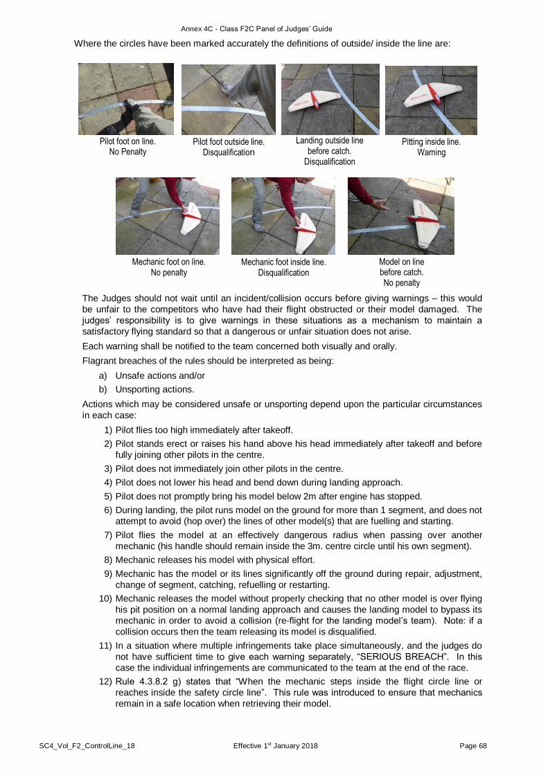
Annex 4C - Class F2C Panel of Judges’ Guide
SC4_Vol_F2_ControlLine_18 Effective 1st January 2018 Page 68
Where the circles have been marked accurately the definitions of outside/ inside the line are:
The Judges should not wait until an incident/collision occurs before giving warnings – this would
be unfair to the competitors who have had their flight obstructed or their model damaged. The
judges’ responsibility is to give warnings in these situations as a mechanism to maintain a
satisfactory flying standard so that a dangerous or unfair situation does not arise.
Each warning shall be notified to the team concerned both visually and orally.
Flagrant breaches of the rules should be interpreted as being:
a) Unsafe actions and/or
b) Unsporting actions.
Actions which may be considered unsafe or unsporting depend upon the particular circumstances
in each case:
1) Pilot flies too high immediately after takeoff.
2) Pilot stands erect or raises his hand above his head immediately after takeoff and before
fully joining other pilots in the centre.
3) Pilot does not immediately join other pilots in the centre.
4) Pilot does not lower his head and bend down during landing approach.
5) Pilot does not promptly bring his model below 2m after engine has stopped.
6) During landing, the pilot runs model on the ground for more than 1 segment, and does not
attempt to avoid (hop over) the lines of other model(s) that are fuelling and starting.
7) Pilot flies the model at an effectively dangerous radius when passing over another
mechanic (his handle should remain inside the 3m. centre circle until his own segment).
8) Mechanic releases his model with physical effort.
9) Mechanic has the model or its lines significantly off the ground during repair, adjustment,
change of segment, catching, refuelling or restarting.
10) Mechanic releases the model without properly checking that no other model is over flying
his pit position on a normal landing approach and causes the landing model to bypass its
mechanic in order to avoid a collision (re-flight for the landing model’s team). Note: if a
collision occurs then the team releasing its model is disqualified.
11) In a situation where multiple infringements take place simultaneously, and the judges do
not have sufficient time to give each warning separately, “SERIOUS BREACH”. In this
case the individual infringements are communicated to the team at the end of the race.
12) Rule 4.3.8.2 g) states that “When the mechanic steps inside the flight circle line or
reaches inside the safety circle line”. This rule was introduced to ensure that mechanics
remain in a safe location when retrieving their model.
Pilot foot outside line. Disqualification
Landing outside line before catch.
Disqualification
Pitting inside line. Warning
Mechanic foot on line. No penalty
Mechanic foot inside line. Disqualification
Model on line before catch. No penalty
Pilot foot on line. No Penalty
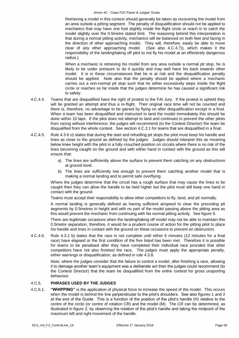
Annex 4C - Class F2C Panel of Judges’ Guide
SC4_Vol_F2_ControlLine_18 Effective 1st January 2018 Page 69
Retrieving a model in this context should generally be taken as recovering the model from
an area outside a pitting segment. The penalty of disqualification should not be applied to
mechanics that may have one foot slightly inside the flight circle or reach in to catch the
model slightly over the 0.5metre stated limit. The reasoning behind this interpretation is
that during a normal pitting activity, mechanics will be balanced on both feet and facing in
the direction of other approaching model. They will, therefore, easily be able to move
clear of any other approaching model. (See also 4.C.4.7)), which makes it the
responsibility of the landing/taking off pilot to not fly his model at an effectively dangerous
radius.)
When a mechanic is retrieving his model from any area outside a normal pit stop, he is
likely to be under pressure to do it quickly and may well have his back towards other
model. It is in these circumstances that he is at risk and the disqualification penalty
should be applied. Note also that the penalty should be applied where a mechanic
carries out a non-normal pit stop such that he either excessively steps inside the flight
circle or reaches so far inside that the judges determine he has caused a significant risk
to safety.
4.C.4.4. Teams that are disqualified have the right of protest to the FAI Jury. If the protest is upheld they
will be granted an attempt and thus a re-flight. Their original race time will not be counted and
there is, therefore, no advantage to be gained by flying on after disqualification except in a final.
When a team has been disqualified and instructed to land the model immediately this should be
done within 10 laps. If the pilot does not attempt to land and continues to prevent the other pilots
from racing without interference, the judges will recommend (to the Contest Director) the team be
disqualified from the whole contest. See section 4.C.2.1 for teams that are disqualified in a final.
4.C.4.5. Rule 4.3.6 o) states that during the start and refuelling pit stops the pilot must keep his handle and
lines as close to the ground as defined by the judges. Judges should interpret this as meaning
below knee height with the pilot in a fully crouched position on circuits where there is no risk of the
lines becoming caught on the ground and with either hand in contact with the ground as this will
ensure that:
a) The lines are sufficiently above the surface to prevent them catching on any obstructions
at ground level.
b) The lines are sufficiently low enough to prevent them catching another model that is
making a normal landing and to permit safe overflying.
Where the judges determine that the circuit has a rough surface that may cause the lines to be
caught then they can allow the handle to be held higher but the pilot must still keep one hand in
contact with the ground.
Teams must accept their responsibility to allow other competitors to fly, land, and pit normally.
A normal landing is generally defined as having sufficient airspeed to clear the preceding pit
segments by 0.5metres in height and with no part of the model passing above the pitting area as
this would prevent the mechanic from continuing with his normal pitting activity. See figure 5.
There are legitimate occasions when the landing/taking off model may not be able to maintain this
0.5metre separation, therefore, it would be a prudent course of action for the pitting pilot to place
his handle and lines in contact with the ground on these occasions to prevent an obstruction.
4.C.4.6. Rule 4.3.1 b) states that the race is not complete until either 6 minutes (12 minutes for a final
race) have elapsed or the first condition of the five listed has been met. Therefore it is possible
for teams to be penalised after they have completed their individual race provided that other
competitors have not also finished the race. The judges must apply the appropriate penalty,
either warnings or disqualification, as defined in rule 4.3.8.
Note: where the judges consider that the failure to control a model, after finishing a race, allowing
it to damage another team’s equipment was a deliberate act then the judges could recommend (to
the Contest Director) that the team be disqualified from the entire contest for gross unsporting
behaviour.
4.C.5. PHRASES USED BY THE JUDGES
4.C.5.1. “WHIPPING” is the application of physical force to increase the speed of the model. This occurs
when the model is behind the line perpendicular to the pilot’s shoulders. See also figures 1 and 2
at the end of the Guide. This is a function of the position of the pilot’s handle (H) relative to the
centre of the circle (or centre of rotation CR) and the model (M). The CR can be determined, as
illustrated in figure 2, by observing the rotation of the pilot’s handle and taking the midpoint of the
maximum left and right movement of the handle.
Annex 4C - Class F2C Panel of Judges’ Guide
SC4_Vol_F2_ControlLine_18 Effective 1st January 2018 Page 70
4.C.5.2. “BLOCKING” is defined as obstructing another pilot either by body position or arm position
preventing the other pilot from taking his correct piloting location, thus slowing down his model.
See figure 1d. Blocking is caused by the position and attitude of the body of the blocking pilot.
With the body between lines 3 and 4 blocking can be caused. Rotation of the shoulders can
cause more (a) or less (c) blocking action. Warnings should be given as soon as the overtaking
pilot is impeded. Delays can lead to more serious and potentially dangerous situations occurring.
Pilots being blocked by a slower opponent will frequently attempt to clear the situation by crossing
lines.
Where the blocking pilot has received a warning for this, but remains in the same position, then
the overtaking pilot should not be penalised for line crossing for a short period while he clears the
obstruction. Excessive blocking to directly prevent being overtaken is a disqualification offence.
4.C.5.3. “PIVOTING” is defined as keeping the handle in the centre of the circle with the pilot’s body
behind the centre. May also be called as “BEHIND CENTRE”.
4.C.5.4. “TAKING THE CENTRE” is defined as the pilot physically keeping his body in the centre and
forcing the other pilots to walk around him. This can also occur when the pilot does not return to
walking forward after the completion of his overtaking manoeuvre.
4.C.5.5. “LINE SHORTENING” occurs when either.
a) The centre of rotation is in front of the pilot’s handle or
b) The handle is pulled back from its correct position in front of the body.
4. C.5.6. “ILLEGAL HANDLE POSITION” occurs when the pilot does not fly in accordance with rule
4.3.6 i) this is frequently a precursor to a blocking situation.
4. C.5.7. “PILOT INTERFERENCE” is defined as:
a) Holding.
b) Pulling another pilot such that the pilot’s normal activities are impeded.
c) Preventing another pilot from moving around correctly by raising his arm/elbow to occupy
the “free space”.
d) Warnings should not be given when a pilot only touches another pilot to help his
orientation.
4.C.5.8. “PILOTS GO TO THE CENTRE” is necessary because the pilots’ rotational centre can move
them towards the edge of the 3 m circle potentially causing problems of lack of space for
landing/taking off pilots. Warnings will not be given directly to pilots failing to respond to this
advice. However, penalties will be given for other infringements that may result from pilots failing
to respond to the advice in a controlled and fair manner.
4.C.5.9. “STOP RACING – SAFETY” when this command is given by the judges all the teams must
immediately respond to it and the race will be declared null and void (after the application of any
appropriate penalties). This command will only be given when, in the view of the judges that there
is an immediate, significant safety risk. It is expected that the FAI Jury would support this course
of action.
4.C.5.10. “SERIOUS BREACH – DISQUALIFIED” will be used by the judges where a team is guilty of
multiple simultaneous rule infringements that need immediate action to prevent a more serious
flying situation developing.
4.C.6. GENERAL POINTS
4.C.6.1. The draws for flying order should be made by the F2C Contest Director in the presence of the
judges as early as possible so that competitors are given the maximum time to prepare.
For the semi-finals both rounds are drawn at the same time using a matrix.
4.C.6.2. Semi-final draws. If three competitors of one nation have qualified, then they are placed
diagonally across the matrix (A); other multiple nations are placed in the matrix randomly across
the X axis (B).
A B F The 1st round is selected horizontally
B A D The 2nd round is selected vertically.
C E A In each case a random draw is made to determine segment choice and order of the
races.

Annex 4C - Class F2C Panel of Judges’ Guide
SC4_Vol_F2_ControlLine_18 Effective 1st January 2018 Page 71
4.C.6.3. All qualifying and semi-final races with only two teams (for example if a team withdraws) will be
put at the end of the round in order to allow the third team (either re-flight or semi-final standby) a
reasonable time to prepare. If necessary, a new draw for pitting segments will be made under the
responsibility of the judges.
4.C.6.4. In the case of re-flights there will be a new draw for pitting segments (unless it is a complete re-
flight of the same three teams).
4.C.6.5. Rule 4.3.5 b) states that the judges will call for volunteer teams to fill up (to make it a 3-up race) a
qualifying race whenever there is a single contestant remaining for a re-flight. Wherever possible
competitors having an obvious interest in the semi-final stage or team classification should not be
accepted as volunteers. At a World or Continental Championships the volunteering teams must
be of different nationalities from each other and also from the single contestant.
Where the volunteer team is not responsible for the termination of a race it will remain eligible for
any official re-flight of that race.
4.C.6.6. The judges should take an interest in the processing of the competitors’ models as part of its
overall responsibility to ensure a fair and even standard for all competitors.
4.C.6.7. Rule 4.3.4 a) states that “the tank …. must be accessible and capable of being measured
accurately”. As these units become ever more complex and unique, the judges support the
following statements:
a) It is the competitor’s responsibility to supply any specialist equipment other than the
normal flexible fuel tubing that is required to link the measuring equipment with the
competitor’s models fuel system.
b) Organisers are only required to make two correctly executed attempts to measure the
capacity of the system at the officially designated processing time.
c) If the system cannot be verified by two attempts then the competitor will be allowed to
return after the end of the official processing time to complete the verification of the
system, with a further two attempts.
Diagrams (Figures 1 to 5) appear overleaf.

Annex 4C - Class F2C Panel of Judges’ Guide
SC4_Vol_F2_ControlLine_18 Effective 1st January 2018 Page 72
Annex 4D – Class F2D Judges Guide
SC4_Vol_F2_ControlLine_18 Effective 1st January 2018 Page 73
- ANNEX 4D -
CLASS F2D – JUDGES GUIDE
Purpose of this Guide
This Guide is intended as an aid for Judges/Circle Marshals, Officials and Organisers as well as Competitors on how to interpret, understand and use the Sporting Code rules concerning F2D Combat.
Most of the content in this guide can also be used for class F2E.
Processing (before the contest)
At processing, before the contest, the following issues should be checked and/or tested:
1. Measurement of:
a) the venturi inlet diameter using the simple plug gauge;
b) the silencer outlet diameter using the simple plug gauge;
c) the silencer volume by filling with an appropriate liquid (oil or other);
d) the interconnecting chamber (maximum volume 1,75 cm3);
e) of the silencer length;
f) of the swept volume of the motor(s) (random check).
2. Inspect the:
a) silencer's internal compartment to determine if it is truly "simple" ie that it is an empty container with no internal components and a single exhaust opening;
b) working shut-off;
c) streamer retaining device.
3. Check:
a) the wing area and model weight;
b) that the model is marked with the FAI Licence Number or the FAI Unique ID number (minimum size specified in CIAM General Rule C.11.1 a) i).
c) the FAI sticker and that the Model Specification Card (one per model type) is properly completed, signed and stamped.
Note: Although checked at processing this does not certify that a competitor’s equipment cannot be a source of disqualification in the competition.
4. Mark the models and engines and record the number of models and engines
5. Pull test the safety strap and safety wire and check that the safety strap works properly.
Rule 4.4.3. Combat Site
If the centre (pilot) circle is laid out on other material other than grass, it is recommended that this material have a maximum radius of 4 metres although the pilot (centre) circle must be marked with a radius of 2 metres.
Circles are best marked using white paint or chalk but plastic strip can be used except for the pilots’ circle. If plastic strip is used, the organiser must make sure it is laid out and fastened in such a way that it will not cause a trip hazard to pilots or mechanics.
Contestants not directly involved in the organisation or flying in a heat should always be requested to withdraw behind the safety fences or outside the contest area. Spectators and others not involved in the Combat Contest must at all times stay behind the safety fences or at the designated places.
The organisers should provide special safety fences for the Scorers/Time Keepers. Judges and Team Managers should also use this safety measure as intended when flying is in progress.
The safety strap and shut-offs must be used during practice flights.
Rule 4.4.4. Competitor
There is no rule saying that the mechanic(s) must be of the same nationality as the competitor. This means that a single competitor from a country can find and employ mechanics at World or Continental Championships. The only requirements are that they possess a valid Sporting Licence and are not registered for another National Team.

Annex 4D – Class F2D Judges Guide
SC4_Vol_F2_ControlLine_18 Effective 1st January 2018 Page 74
When the pilot is outside the centre circle for reasons other than picking up the handle or waiting for his model to be serviced, all rules that apply to mechanic(s) also apply to the pilot.
Rule 4.4.5. Characteristics
b) All handle and line connections should be covered in such a way so as not to interfere with the opponent’s lines but may not be longer than required to cover the connectors. More than one connector per line at the handle and at the model aircraft is not permitted. Note that open connection connectors are not allowed (see sketch). Pilots using this type of handle must tape the handle before the heat.
f) There must always be a safety wire connection between the engines and the lines.
h) No sharp edges, abrasive or sticky areas that might assist the cutting of the streamers are allowed on the model.
k) When referring to the engine shut-off (engine stop) device this covers both the anti fly-away device (shut-off) and the system used to stop the engine at the pilots will.
Rule 4.4.6. Technical Verification
d) Demonstrations of a working shut-off can be requested at random by an official.
e) When pull testing the safety wire it is recommended to ask the competitor (owner of the model) in which direction to pull.
Rule 4.4.8 Streamer
The mechanic(s)/pilot may not ask for another streamer just to save time in a heat; for example if it is wrapped around the lines or if a fly-away occurs. If a fly-away occurs and the model is stuck up in a tree or a net or is unable to be reached, the pilot may choose to continue with a new full length streamer instead of having a reflight (if granted be the Judges).
All parts of the opponent’s streamer/string should be cleared from the pilot’s own streamer/string before re-launching.
No matter that the competitor uses a metal ring or not to attach the streamer to the model, the string should have a single loop and one knot.
Rule 4.4.9. The Heat from Start to Finish
f) When the model is launched, the pilot should walk directly into the centre circle. It is the responsibility of the competitor to make sure where the Circle Marshal is to avoid running into him.
h) At take-off and before the signal to start combat the models should fly level in an anti-clockwise & direction. The competitors are not allowed to do any loops or other manoeuvres unless asked to i) do so by the Circle Marshal in order to separate the models. Take-off should take place in level
flight forward, not upwards or backwards. Any contravention of these rules will result in a disqualification.
k) In conditions of heavy wind, a grounded model which does not have a running engine may be moved to a safer launching position under supervision by the Judges. While doing this, the mechanics are not allowed to carry the model aircraft and lines over an opponent’s grounded model aircraft and/or pitting crew. Parts of a crashed model aircraft are not considered a grounded model aircraft. It is a crashing/landing team’s responsibility to maintain a safe distance. If two teams crash/land close to each other it is the rearmost team’s responsibility to move backwards unless they are blocked by the other team’s second model. This will be supervised by the Judges and they will advise the teams if any unclear situation occurs.
l) The mechanic(s)/pilot may move around within their pitting area. A team’s pitting area is considered to be the place where they have one or both of the models and a distance of

Annex 4D – Class F2D Judges Guide
SC4_Vol_F2_ControlLine_18 Effective 1st January 2018 Page 75
approximately 2 metres on each side of the model(s). To assist in untangling lines, mechanics/pilots may be allowed to move around inside the flight circle.
n) The pilot will receive a yellow card if he uses a rough or unsafe flying style, causes a line tangle or if he shows unsportsmanlike behaviour. The Judges/Circle Marshal shall not hesitate to give a yellow card to keep the level of combat on an acceptable and fair level. A yellow card can be given during the heat or after the heat when the Judges/Circle Marshals have had a chance to confer about situations during the heat. The first yellow card is a 40 point penalty while the second and/or third yellow card is a disqualification from the heat. If the first yellow card incident is considered severe, the pilot shall also be disqualified for the offence.
o) The scorers must be observant and aware that the heat can be stopped.
p) If he chooses to bring the model back closer to the pitting circle, the model and remaining lines should be left at least three metres outside the pitting circle. If the model lands in the pitting circle, or close to it , the model and remaining lines must be collected and kept within the pitting area. The purpose of this is to make sure that there is a clear path for mechanics when running between pitting positions.
The landings shall be supervised and directed by the Circle Marshal to avoid dangerous
situations.
Rule 4.4.10. Scoring
b) No matter what part of the pilot’s equipment (model, propeller, lines, streamer etc) makes the cut, it should be counted.
c) The scorers’ times should be rounded down to the nearest whole second and then added together. The added result should be divided by the number of scorers, and then rounded down to the nearest whole second. This result should be the competitor’s official time in the heat. If any scorer’s time shows a significant deviation from the average, it should be excluded (but still noted on the score sheet). If a fly-away occurs the scorers should stop the watches when the model lands. It is then the Judges’ responsibility to measure and deduct the number of seconds that occurred between the fly-away and the landing. The same should be done if the pilot is asked to land due to streamer or silencer problems/replacement ie the scorers stop their watches when the model lands and the Judges deduct the measured time from the point of decision until the landing.
Rule 4.4.11. Re-flights
c) A reflight may be granted if, for instance, the model is stuck high up in a tree or in a safety net where it will take too long, or be impossible, to retrieve the streamer. The pilot may choose to continue with a new full length streamer instead of accepting the granted reflight. It is also possible for the Judges to grant a reflight if an unsafe situation occurs and continuing the heat would cause risk to the competitors or others.
The Circle Marshal can also grant a reflight if there is a line tangle where both models are grounded and he considers the tangle impossible to clear. Before a re-flight is called, both pilots should be asked if they would agree to continue the match without clearing the tangle.
Rule 4.4.12. Penalties and disqualifications
A. A competitor will receive a penalty of 40 points:
a) No penalties should be given to the pilot if he is pushed out of the circle. Instead his opponent should receive a yellow card or be disqualified (4.4.12.C.e) unless the Circle Marshal considers it an accidental incident where neither of the pilots is to blame.
cont/…
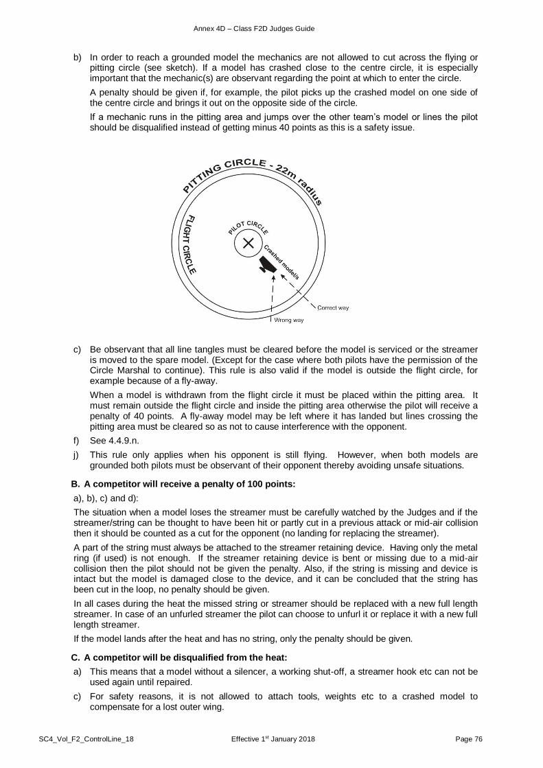
Annex 4D – Class F2D Judges Guide
SC4_Vol_F2_ControlLine_18 Effective 1st January 2018 Page 76
b) In order to reach a grounded model the mechanics are not allowed to cut across the flying or pitting circle (see sketch). If a model has crashed close to the centre circle, it is especially important that the mechanic(s) are observant regarding the point at which to enter the circle.
A penalty should be given if, for example, the pilot picks up the crashed model on one side of the centre circle and brings it out on the opposite side of the circle.
If a mechanic runs in the pitting area and jumps over the other team’s model or lines the pilot should be disqualified instead of getting minus 40 points as this is a safety issue.
c) Be observant that all line tangles must be cleared before the model is serviced or the streamer is moved to the spare model. (Except for the case where both pilots have the permission of the Circle Marshal to continue). This rule is also valid if the model is outside the flight circle, for example because of a fly-away.
When a model is withdrawn from the flight circle it must be placed within the pitting area. It must remain outside the flight circle and inside the pitting area otherwise the pilot will receive a penalty of 40 points. A fly-away model may be left where it has landed but lines crossing the pitting area must be cleared so as not to cause interference with the opponent.
f) See 4.4.9.n.
j) This rule only applies when his opponent is still flying. However, when both models are grounded both pilots must be observant of their opponent thereby avoiding unsafe situations.
B. A competitor will receive a penalty of 100 points:
a), b), c) and d):
The situation when a model loses the streamer must be carefully watched by the Judges and if the streamer/string can be thought to have been hit or partly cut in a previous attack or mid-air collision then it should be counted as a cut for the opponent (no landing for replacing the streamer).
A part of the string must always be attached to the streamer retaining device. Having only the metal ring (if used) is not enough. If the streamer retaining device is bent or missing due to a mid-air collision then the pilot should not be given the penalty. Also, if the string is missing and device is intact but the model is damaged close to the device, and it can be concluded that the string has been cut in the loop, no penalty should be given.
In all cases during the heat the missed string or streamer should be replaced with a new full length streamer. In case of an unfurled streamer the pilot can choose to unfurl it or replace it with a new full length streamer.
If the model lands after the heat and has no string, only the penalty should be given.
C. A competitor will be disqualified from the heat:
a) This means that a model without a silencer, a working shut-off, a streamer hook etc can not be used again until repaired.
c) For safety reasons, it is not allowed to attach tools, weights etc to a crashed model to compensate for a lost outer wing.
Annex 4D – Class F2D Judges Guide
SC4_Vol_F2_ControlLine_18 Effective 1st January 2018 Page 77
f) If lines or handles are dragged into the centre circle by accident, the Circle Marshal should order the pilots to cease combat and fly level until the circle is cleared and it is safe to continue.
h) It is the responsibility of each competitor, and his Team Manager, to be aware of when his flight is scheduled.
m) Crossed lines which do not interfere with the course of the heat are not a problem and is no reason for disqualification. If the spare model aircraft is needed to take-off and it is prohibited by the crossed lines of the opponent then another situation is created and rule 4.4.12.C.u is applied: Interference with his opponent’s equipment.
o) When a pilot without a streamer chooses to fly level and combat still is going on, and his opponent flies in such a way to cause a crash or collision the opponent will be disqualified.
s) See 4.4.9.n.
t) For example, any tampering with the streamer in any way, shape or form can result in a disqualification. This rule can also be used to disqualify a competitor for any other breach of the rules that is not covered in a separate paragraph.
Rule 4.4.13 The Use of Video Equipment
Note that is only the Judges/Circle Marshal/FAI Jury that can decide whether to look at the video recording or not. A competitor may make a request or his Team Manager may submit a protest after a heat but if the Judges/Circle Marshal feel certain, then they are not obliged to look at the video recording.
Rule 4.4.14 Individual and Team Classification
f) Although this competitor will fly his heat in the following round, his score will count in the round where he was the odd one.
i) A junior fly-off follows the rules in 4.4.14.h.
Rule 4.4.15. Judges and Timekeepers
a) It is most important that the Judges have a good understanding of the rules and that they have a common language as this will reduce delays and possible errors. The Circle Marshal has the main responsibility for the centre circle and the pilots and their behaviour although all the Judges have the right to give penalties. Penalties may be given after a heat when the Judges/Circle Marshal have had a chance to discuss situations that occurred in the heat. In case of three Judges one should be assigned to each pilot and his mechanic(s) while the third Judge will have an overall function. The Judges must work together and watch any models landing/crashing close to them.
b) All scorers should count cuts as well as record airtime for the competitor. Every scorer should have a notepad where he can make records of the number of cuts as well as the air time (after the heat). A good way is to divide the six scorers into three pairs and spread them around the circle. Each pair will consist of a scorer for each pilot and they should be instructed to talk to each other during the scoring. If, after the heat, the scorers have a different cut count they must confer and try to come to a decision. They may also ask the Judges for advice.
It is also recommended that three Scorers per competitor are used at World Cup contests.

SC4_Vol_F2_ControlLine_18 Effective 1st January 2018 Page 78
PAGE DELIBERATELY LEFT BLANK

Annex 4E – Control Line World Cup Rules
SC4_Vol_F2_ControlLine_18 Effective 1st January 2018 Page 79
- ANNEX 4E -
CONTROL LINE WORLD CUP RULES
4.E.1. Classes
The following separate classes are recognised for World Cup competition in Control Line: F2A (Speed), F2B (Aerobatics), F2C (Team Racing) and F2D (Combat).
4.E.2. Competitors
All competitors in the specified open international contests are eligible for the World Cup.
4.E.3. Contests
Contests included in the World Cup must appear on the FAI Contest Calendar and be run according to the FAI Sporting Code. The contests to be counted for a World Cup in a particular year are to be nominated at the CIAM Bureau Meeting at the end of the preceding year and are to be indicated on the FAI Contest Calendar. The selection of the contests for each class should be according to the following guidelines:
a) Any country may host two competitions in each class on its own behalf unless the particular country extends over three or more time zones, when it may host two competitions on its own behalf within each time zone.
Additionally, any country may host a maximum of one competition in each class on behalf of another organising country regardless of whether or not the host country extends over three or more time zones.
b) Each competitor (team in F2C) may count only one competition from each organising country in Europe (taking the better score for any European organising country in which he has scored in two competitions). When two competitions per time zone have been organised and held within a time zone, the better score per time zone counts.
4.E.4. Points Allocation
In each competition, points in a class will only be allocated if the competitors who have completed a flight in that class are from at least two different countries.
A competitor (team in -F2C) has completed a flight if:
• he registers a speed not equal to zero (0) in F2A.
• he registers a score not equal to zero (0) in F2B.
• he registers a time not equal to zero (0) in F2C.
• he flies in a heat in F2D
In F2A, the points allocated to each competitor will be the same as the achieved speed result in km/h.
In F2B, F2C and F2D, the points to be allocated to competitors (teams in F2C) will depend on the number (N) of competitors (teams in F2C) who will have completed at least one flight in the event.
Points are allocated to competitors (teams in F2C) who will have completed at least one flight according to their placing in the results given in the following tables:
a) N > 20
Placing 1 2 3 4 5 6 ..... 20 21 and after
Points 20 19 18 17 16 15 ..... 1 0
A bonus of 8 points is given to the first, 5 points to the second and 3 points to the third.
b) N < 20 or N = 20
Placing 1 2 3 4 5 6 ..... N-1 N
Points N N-1 N-2 N-3 N-4 N-5 ..... 2 1
The bonus is defined overleaf

Annex 4E – Control Line World Cup Rules
SC4_Vol_F2_ControlLine_18 Effective 1st January 2018 Page 80
The bonus is defined as follows:
• for first: N/3 rounded up to the nearest whole number of points with a maximum of 7 points;
• for second: N/5 rounded up to the nearest whole number of points with a maximum of 4 points;
• for third: N/7 rounded up to the nearest whole number of points with a maximum of 3 points
In the event of a tie for any placings, the competitors (teams in F2C) with that placing will share the points which would have been awarded to the places covered had the tie been resolved (round up the score to the nearest whole number of points).
4.E.5. Classification
The World Cup results are determined by considering the total of points obtained by each competitor (team in F2C) in the World Cup events. Up to three events may be counted, selecting each competitor’s (teams in F2C) best scores during the year. The winner of the World Cup is the competitor (team in F2C) with the greatest total.
In the event of a tie for first, second and third place, the place will be determined according to the following scheme. The number of events counted is increased from three, one at a time, until the place is obtained. If this does not separate the tied competitors then the winner will be determined by considering in the best three events:
• in F2B and F2D the points obtained in each event multiplied by the number of competitors who will have completed at least one flight in the event; the winner is the one with the greatest total thus calculated.
• in F2A the best speed and in F2C the best time.
4.E.6. Awards
The winner is awarded the title of the winner of the World Cup. Further medals, trophies or certificates may be awarded by the CIAM F2 Subcommittee as available.
4.E.7. Organisation
The F2 Subcommittee shall be responsible for organising the World Cup and may nominate a responsible person or special subcommittee to collect the results.
4.E.8. Communication
The F2 Subcommittee should receive the results from each contest in the World Cup and then calculate and publish the Current World Cup positions. These should be distributed to the news agencies and should also be available, by payment of a subscription, to any interested bodies or individuals. Final results of the World Cup are to be sent also to the FAI, National Airsports Controls and Model Aircraft press.
4.E.9. Responsibilities of Competition Organisers
Competition organisers must propose their event for inclusion in the World Cup when nominating events for the FAI International Sporting Calendar. The final selection of events from these proposals is made by the CIAM Bureau as defined in paragraph 3. Immediately after the event, the competition organiser must send the results to the World Cup organiser, at least within one month as required in the Sporting Code B.5.5. Any failure to return results promptly will be reviewed by the CIAM Bureau when considering the competition calendar for the following year.
4.E.10. Board of Judges
A Board of three persons shall be nominated by the F2 Subcommittee Chairman in accordance with CIAM General Rules C.7.4 World Cup Board.

Annex 4F – Control Line Organisers’ Guide
SC4_Vol_F2_ControlLine_18 Effective 1st January 2018 Page 81
- ANNEX 4F -
CONTROL LINE ORGANISERS’ GUIDE
Foreword: This guide is intended to give some helpful advice to organisers of international contests. The guide should be looked upon as a set of recommendations concerning contest organising, and the statements are in no way to be regarded as definite rules except in those cases when they quote the Sporting Code. This guide is written for World Championships, but can be used for any international competition. If so, compare with the Sporting Code for deviations.
FIRST PART: PRE-CONTEST ARRANGEMENTS
Contents:
Information ............................................ 1
Publicity ................................................. 2
Time Schedule ...................................... 3
Practice Flights ...................................... 4
Awards .................................................. 5
Contest Ground: .................................... 6
General ........................................... 6.1
Lay-out ............................................ 6.2
Depots ............................................ 6.3
Site ................................................. 6.4
Tracks: ............................................ 6.5
Speed ....................................... 6.5.1.
Aerobatics ................................. 6.5.2.
Team Racing ............................ 6.5.3.
Combat ..................................... 6.5.4.
PA Systems ........................................... 7
Equipment: ............................................ 8
Speed ............................................. 8.1
Aerobatics ....................................... 8.2.
Team Racing ................................... 8.3
Combat ........................................... 8.4
Secretariat (including: processing) ... 8.5
Officials and Judges: ............................. 9
Contest management ...................... 9.1
FAI Jury .......................................... 9.2
Speed ............................................. 9.3
Aerobatics ....................................... 9.4
Team racing .................................... 9.5
Combat ........................................... 9.6
Emergency - First aid............................. 10
Insurance .............................................. 11
Accommodation ..................................... 12
Food ...................................................... 13
Fuel ....................................................... 14
For the time schedule for organising World and European Championships and the information required by the CIAM Bureau, see General Organisation of a World Championship.
Appendix I: Team Racing circle dimensions.
Appendix II: Aerobatics circle dimensions
Appendix III: Speed circle dimensions

Annex 4F – Control Line Organisers’ Guide
SC4_Vol_F2_ControlLine_18 Effective 1st January 2018 Page 82
1. Information
1.1. The offer to organise will be given not later than at the CIAM Plenary meeting the year previous to the WCh/CCh.
1.2. First information can be given at the next Plenary meeting.
1.3. First information to intended judges and jury members should preferably be distributed not later than 1st January of the year of the WCh. This information is that approved by the CIAM Bureau at the previous December meeting.
The jury members must be chosen according to CIAM General Rule C.7.1.
The Judges must be chosen from the approved FAI list of judges and according to Sporting Code CIAM General Rule C.7.5 and Volume F2 Section 4C para. 4.2.11, 4.3.13. and 4.4.15.
1.4. Information to National Airsports Controls and entry forms must be dispatched in accordance with CIAM General Rule C.15.4. This information must contain date, place, time, schedule and name and address of contact person. It is possible to ask for a preliminary number of entrants at an early stage and have this figure completed with names at a later date but not later than one month before the competition.
1.5. Information to the CIAM Bureau shall be given by a delegate from the organising nation at the Bureau meeting in the December prior to the competition.
This information shall include jury and judges according to CIAM General Rules C.7.1 and C.7.5 and Volume F2 rules 4.2.11, 4.3.13 and 4.4.15.
An example of this information is given in General Organisation of World Championships.
1.6. The organiser must acknowledge receipt of the entry form and the entry fees (CIAM General Rule C.13.4 c)). This should be done in due time before the contest.
2. Publicity
2.1. A first set of information to national press, radio and TV can be dispatched about half a year before the contest. It should contain common information about model flying and some basic information about the international contest which is to be run.
2.2. Simultaneously a set of information should be sent to the international model flying press.
2.3. About two months before the contest, an information meeting should be arranged with invited guests from the main national newspapers and radio and TV.
At this stage it should be possible to release detailed information about the contest, such as the number of entrants, etc.
2.4. A second set of information should be distributed as 2.1. and it should contain mainly the same information as given under 2.3. It should also be sent to the international model flying press.
2.5. Press conferences to be held during the contest should be prepared.
2.6. Posters about the contest should be distributed at least in the city where the contest area is located about one month prior to the contest.
cont/…
Annex 4F – Control Line Organisers’ Guide
SC4_Vol_F2_ControlLine_18 Effective 1st January 2018 Page 83
3. Time Schedule
3.1. A common time schedule for Control Line WCh/CCh is as follows:
F2A: The round start time should be set so that the round will finish at approximately 18.00. This time should be calculated to include 30% of the entry anticipated to make second attempts. Round four should be scheduled to finish immediately prior to the F2C final.
4. Practice Flights
4.1. The fact that some teams prefer to arrive several days in advance for practice flying should be considered. Accommodations should be arranged or at least advised prior to the contest, and the tracks or any suitable area in the neighbourhood must be open for flying.
4.2. During the contest it should be possible to perform practice flights within the contest area or in another suitable place close to it. The tracks should be open for test flights whenever they are not used for contest rounds, except for Combat.
4.3. If space permits an extra circle for test flying is recommended within the contest site.
4.4. If test flying only can be arranged far away from the contest site a transportation system of suitable frequency (e.g. mini-buses) must be available.
5. Awards CIAM General Rule C.21.
5.1. The organiser should contact the FAI and the CIAM Secretary to confirm that perpetual trophies, diplomas and medals are delivered to the contest in due time.
5.2. If there is any intention to offer a new perpetual trophy, it should be approved by the CIAM Plenary Meeting the year before the contest.
6. Contest Grounds
6.1. General
The site should be chosen in such a way that the following are considered:
6.1.1. Distances between accommodation - meal places - contest ground should be kept to a minimum.
6.1.2. Easy transports for entrants and spectators. Bus tours should be organised.
6.1.3. Parking areas for entrants and spectators.
6.1.4. Noise problems (if any).
6.1.5. Windy places should be avoided, if possible.
6.1.6. Turbulence caused by trees or houses surrounding the circle (especially for Aerobatics) should be avoided.
cont/…
1st day Arrival
F2A F2B F2C F2D
2nd day Processing, Official training, Opening ceremony
3rd day 1st Round 1st Qualifying flights
1st Round Eliminating round
4th day 2nd Round 1st / 2nd Qualifying flights
2nd Round Eliminating round
5th day 3rd Round 2nd Qualifying flights
3rd Round Eliminating round
6th day Free training 2nd Qualifying flights
Eliminating round
7th day 4th Round Fly off rounds Semi-finals, and finals
Semi-finals, and finals
8th day Departure

Annex 4F – Control Line Organisers’ Guide
SC4_Vol_F2_ControlLine_18 Effective 1st January 2018 Page 84
6.1.7. Site and surroundings must not be dusty (dust clouds in the contest area might well damage the engines). Grass is to be preferred in between the circles.
6.1.8. If possible, areas for test flying close to the contest area (test flights might interfere with the contest).
6.1.9. Public conveniences must be available at the contest area.
6.2. Layout
6.2.1. The area should preferably contain three hard circles and, if Combat is included two grass circles. The circles shall be horizontal. The distances between the circles must permit safe passage of pedestrians while the model aircraft are flying.
The circles should not be too widely spread as this will cause communication problems for the teams and the officials.
For Combat, the circles should be laid out on grass.
6.3. Depots
6.3.1. Sufficient area for depots must be provided. The depots should be placed within the contest area and they can be of open air, tent or indoor type. They should preferably be equipped with a sun- or rain- shades.
6.3.2. Avoid putting the depots so close to the tracks that motor testing interferes with the starting procedures.
6.3.3. The depots should be organised in such a way that spectators cannot obtain access to them. They should be easily entered by the competitors.
6.3.4. The depots should preferably be equipped with an area ( 4 m x 24 m per nation) where model aircraft with lines and handles assembled can be put. This area can be marked by cloth bands on short poles.
6.3.5. Tables and chairs in each depot are always appreciated.
6.4. Site
6.4.1. The contest site should be fenced off so spectators can be outside it. Places for spectators should thus be placed outside the limits of the area although as close to it as possible.
6.4.2. The different hard circles should be made of tarmac, asphalt or similar material. The surface shall be smooth without rough joints and free from grit and dust. It is recommended to have the tracks leaning slightly outwards so water is not collected on them.
The Combat circles should be laid out on grass. The centre piloting circle may be laid out on grass or any other suitable (non-slippery) material having a radius of maximum 4 metres.
6.4.3. Except for Combat, the best track is the one where the complete circle area is made of the same material. If there is grass or gravel between the centre circle and starting and landing circles there is a risk that lines are caught thus causing accidents.
6.4.4. Except for Combat, if the flying surface is shaped like a ring, then enough space must be left both inside and outside the 19.6 m circle to permit normal foot work to the pilot for safe take-off and landing without the model aircraft falling outside the smooth area.
For Combat a space of at least 5 metres should be left free around the pitting circle to position scorers/timekeepers, team managers and judges with their protective fences and to give space to the pitting crews (when running).
6.4.5. The central part of the flying circle must be smooth, but not slippery, especially in case of rainy weather (rough tarmac, rough concrete or coating with special anti-slip paints is recommended). Its radius must be sufficient to permit take-offs and landings.
6.5. Tracks
6.5.1. Speed
6.5.1.1. The Speed circle must be surrounded by a fence (see rule 4.0.1). It should be placed as close to the track as possible, but the radius must not be less than 24 m. There should also be a place for timekeepers, officials and their equipment.
6.5.1.2. In case of a permanent installation (especially near the sea), checks must be made for any rust or corrosion reducing its strength.
cont/…

Annex 4F – Control Line Organisers’ Guide
SC4_Vol_F2_ControlLine_18 Effective 1st January 2018 Page 85
6.5.1.3. On the fence, diametrically opposite to the timekeepers' place, there should be a mark on the fence, preferably a white board, 20 cm wide and at least 2 m high. It should be placed at the normal flight level at 1 - 3 m height.
6.5.1.4. At three evenly spread places there shall be T-marks showing the flight heights of 1 m, 3 m & 6 m.
6.5.1.5. The fence shall have one entrance and one exit opposite to each other.
6.5.1.6. Just outside the entrance there shall be a line control area, fenced off with a low fence or a rope. In this area the line length 17.69 m will be marked by marks firmly fixed to the ground. The marks should preferably be of the edge type, and the edges not wider than 2 mm.
6.5.1.7. In the centre of the circle there shall be a Speed pylon according to para. 4.1.7. The pylon must be firmly fixed to the ground.
6.5.1.8. Any protruding part which may engage the pilot’s clothes must be avoided on the lower (non-rotating) parts of the pylon.
6.5.1.9. The pylon must be checked for sufficient stiffness in the fully extended position. The pylon must reach a sufficient height to permit flying with the handle at shoulder level.
6.5.1.10. The device which holds the upper (rotating) part of the pylon at the height chosen by the pilot, must be built in such a way that it assures a positive positioning avoiding any displacement during the official flight. Checks are recommended in this respect, in case of an old pylon, after prolonged use and wear.
6.5.1.11. The swivel must be free from any appreciable friction or stiffness.
6.5.1.12. Any eventual bolts for fixing the pylon to its base or the ground must be under ground level or conveniently covered flush to the ground, so the pilot is allowed to run around the pylon with his feet close to it without hindrance. If the pylon has a flange for fixing it to the ground, the same aspects should be regarded.
6.5.1.13. The judges and the timekeepers should be placed in a special area with a safety fence between themselves and the flying models. The area must be chosen so the officials have the sun behind their backs, and so it does not interfere with the timekeeping.
6.5.1.14 When a duplex electronic timing system is used, the sensors shall be placed in a shaded area facing away from the sun. Care should be taken to ensure that no moving shadows cross the sight path of the sensors.
6.5.2. Aerobatics
6.5.2.1 Contest organisers shall provide a site with one or more Contest Flight Circle/s that are, relative to the centre of the circle, horizontal within plus/minus 30 cm across the entire diameter of each circle. Contest Flight Circles shall also be flat and have smooth and ridge-free surfaces. If surfaced in asphalt, concrete, or similar hard material, the surface should be dust-free (that is: not packed gravel or sand, nor paved or tiled with openings between the paving material). Hard surfaces should, as a minimum, provide sufficient hard area to include at least the whole of the pilot’s circle plus a "ring" for model aircraft to use during take-off and landing (see diagram). During contest flying all grass, soil, etc, lying between these 2 areas shall be kept short enough and level so as not to interfere with control lines when model aircraft are taking-off and landing.
6.5.2.2 If Contest Flight Circle/s are wholly grass (or similar), the same requirements as in paragraph a) above shall apply, and also, the centre (pilot’s) circle and take-off and landing area should have an underlying surface which is free from any bumps and/or holes. The standard required shall be better than that of a typical local sports field (a football field for example), and should be as close as possible to a high quality, level, well-tended and well-drained domestic lawn. The length of grass shall be kept to a maximum of 2.5 cm over the complete Contest Flight Circle during contest flying.
6.5.2.3 The diagram at Appendix II shows the recommended dimensions for Contest Flight Circles and the recommended markers to be erected every 1/8th of a lap interval indicating the height of the horizontal base which lies 1.5 m above the centre of the circle. As a minimum standard, all Contest Flight Circle/s shall have the centre (pilot’s) circle and outer diameter circle clearly marked with lines of 10 cm width. The erection of a safety fence (or other suitable barrier) around the outside of all Contest Flight Circles as shown below is also highly recommended.
6.5.2.4 The use of "Ready Box"/es is recommended at all contests. These should be clearly marked, segregated from general access by barriers, and be large enough to contain a model aircraft with full-length lines attached. Ideally three such Ready Boxes should be provided if the site is large enough. It is also recommended that one "Exit Box" is also provided. This should be positioned on
Annex 4F – Control Line Organisers’ Guide
SC4_Vol_F2_ControlLine_18 Effective 1st January 2018 Page 86
the opposite side of the Contest Flight Circle to the Ready Box/es, of a similar size to the Ready Box/es, and similarly marked and segregated.
6.5.2.5 At World and Continental Championships and other limited international contests, organisers shall also provide Practice Circle/s. These shall be located at the contest site itself, but in any event shall not require more than 30 minutes of normal travelling time to reach from the contest site. Organisers should provide a minimum of one Practice Circle for every 50 registered contestants. All Practice Circles shall be freely open and available for use by all contestants for at least the duration of the contest, plus also for a suitable time before the start of the contest. All Practice Circles should be as close as possible to the standard and maintenance conditions set out at paragraphs a) and/or b) above; but except for the marking of the centre of the centre (pilots') circle and the outside diameter circle, the marking of circles as described at paragraph c) above shall not be required. However if the Practice Circle/s site is open to public access then organisers shall also erect suitable safety barrier/s and warning signs in the local language.
6.5.3. Team Racing
6.5.3.1 The centre circle, safety circle and flight circles shall be marked (painted) on the ground in a colour having a high contrast to the ground, according to Sporting Code Volume F2 para. 4.3.2. The circle lines shall be 10 cm wide. The safety circle shall be a broken line consisting of dashes 25 cm long with 25 cm gaps, and a width of 2.5 cm. The radii are:
Inner circle 2.0-2.1 m
Centre circle 3.0 – 3.1 m
Flight circle 19.5 – 19.6 m
Safety circle 19.075 - 19.1 m
The centre of the centre circle shall be marked with a spot of 0,3 m diameter in the same colour as the circles. See Appendix I.
6.5.3.2. The Team Race circle must be surrounded by a fence 2,5 m high (see rule 4.0.1). It should be placed as close to the track as possible but the radius to the circle centre shall not be less than 24 m.
6.5.3.3. In case of a permanent installation, checks must be made for any rust or corrosion (especially near the sea) reducing its strength.
6.5.3.4. Wire fences 2 to 2,5 m height and 2 to 2.5 m wide must be provided to protect all staff who have to be inside the circle during races. These fences may also be used by pitmen and team managers. The judges must also be provided with a similar safety fence.
6.5.3.5 At three evenly spread places there shall be T-marks showing the flight heights of 2 m, 3 m & 6 m.
6.5.3.6. The fence shall have separate entrance and exit areas to allow a smooth flow of entrants at the end and beginning of each race.
6.5.3.7. Just outside the entrance there shall be a line control square at least 4 m x 18 m, fenced off with a low fence or rope. In this square, the line length 15,92 m shall be marked by two marks firmly fixed to the ground. The marks should preferably be of the edge type, and the edges not wider than 2 mm.
6.5.3.8. In the square there should be signs showing where to keep the handles and where to keep the model aircraft. As motor running is allowed in the square while a race is running, the model aircraft should be kept away from the Panel of Judges.
6.5.3.9. The Panel of Judges is preferably placed on a raised floor about 2 m above the ground just outside the safety fence. There shall be a 6 m high tower for one official checking high flying model aircraft. The Panel of Judges must be placed close together having the sun behind their backs.
6.5.3.10. At the track there shall also be three lap-counting displays, big enough to be clearly seen from the track, and three sets of warning indicators. There shall be a fourth set of lights in the colours of the three teams to display the fourth (disqualification) warning.
6.5.4. Combat
6.5.4.1. The Combat track should consist of short cut grass.
6.5.4.2 The centre (piloting) circle (radius 2 m) the flight circle (radius 20 m) and the pitting circle (radius 22 m) must be clearly marked on the ground.
The centre piloting circle may be laid on grass or any other suitable non-slippery material that has a maximum radius of 4 metres.
6.5.4.3. The track should be fenced off with low fences or rope or by other means. A football ground or similar is ideal. A safety fence with a minimum height of 3 metres (5 metres preferred) should

Annex 4F – Control Line Organisers’ Guide
SC4_Vol_F2_ControlLine_18 Effective 1st January 2018 Page 87
protect all spectator areas. If a stand is being used for spectators then the net should be of a corresponding height.
Fabric nets with meshes of around 12 cm are ideal. The meshes should not be so small as to impede the visibility of the model aircraft and streamers for the spectators.
6.5.4.4. A square for processing and line tests shall be arranged. It should contain two line length marks 15.92 m apart and protected by a meshed fence of 3 m height. For the administration and other officials their working area should be protected by a meshed fence of minimum 3 m high.
6.5.4.5. The judges, time-keepers/scorers and team managers should be protected by small mobile fences of 2 to 2.5 m height and 1.5 to 2 m width. Placing 6 of these around the pitting circle will be adequate.
6.5.4.6 In an attempt to stop fly-way models, even if they have a workable engine shut-off, from leaving the flying site in unwanted directions long posts with a safety net can be erected outside parts of the pitting circle. Only the competitor, his helpers and the officials are allowed to stay inside the safety fences or safety circles. Persons who have fulfilled their mission must leave the flying area.
7. PA Systems
7.1. One system addressing the spectators.
7.2. One system addressing the entrants, calling them for flights, etc.
7.3. One system to be used by the Team Race jury addressing teams during their races.
7.4. Fixed devices are needed in Combat and are very useful in Speed and Aerobatics.
Note: 7.1. and 7.2. can be combined. 7.3. cannot be combined with any other use.
8. Equipment
8.1 Measuring Equipment Specification:
The contest organisers should procure the following minimum equipment for use at the Championships:
8.1.1 Line Measuring
8.1.1.1 A good quality electronic digital reading micrometer, constructed to DIN 863 or equivalent standard, fitted with a friction thimble, with measuring graduations of 0.001 mm and with an accuracy of +- 0.001 mm. The instrument should have a recent calibration certificate. (This will resolve any anticipated problems with the thimble torque.)
8.1.1.2 Three lever operated thickness gauges with measuring graduations of 0.01 mm for Speed, Team Race and Combat.
8.1.1.3. Pin gauges of 0.35 mm for Team Race and 0.4 mm diameter for Speed and Combat to DIN 2269 standard to calibrate the micrometer and thickness gauge.
8.1.2 Engine Measuring
8.1.2.1. For measuring the bore a minimum of a self-centring (three-point) micrometer gauge with a minimum graduation of 0.005 mm and an accuracy of +- 0.002 mm should be used. A standard sizing ring appropriate to the instrument and manufactured to the appropriate DIN standard must also be supplied in order to calibrate the bore gauge prior to use.
8.1.2.2 For measuring the stroke a dial gauge with a minimum of 20 mm travel, a minimum graduation of 0.01 mm and an accuracy of +- 0.020 mm fitted with a suitable stop to rest on the top of the liner should be used. For measuring an engine which is close to top limit of capacity, a 0 to 25 mm depth micrometer with minimum graduations of 0.005 mm and an accuracy of +- 0.002 mm should be used. The dial gauge is the preferred instrument for stroke measurement because of its ease of use.
8.2 Measuring Equipment Method of Use
8.2.1 Methodology for Line Measuring Equipment
The pin gauges should be used to set a zero on the thickness gauge, which is light, easy to use and requires minimum skill to operate. The calibrated digital micrometer would only be used in the case of a dispute where lines are at or near bottom limit. An electronic digital micrometer is specified because it is much easier to use and clearer to read. It must be fitted with a friction thimble and not a ratchet thimble.
8.2.2 Methodology for Engine Measuring Equipment
There are different problems associated with measuring Speed, Combat and Team Race engines. These problems are related to the fit and construction of Team Race engines.
Annex 4F – Control Line Organisers’ Guide
SC4_Vol_F2_ControlLine_18 Effective 1st January 2018 Page 88
8.2.2.1 Speed & Combat Engines
On engines using removable heads, as commonly used in Speed and Combat and where it is possible to turn the engine over TDC easily, the bore should be measured at or near TDC as currently specified.
The stroke should be measured using the dial gauge supported on a suitable foot and mounted on the top of the crankcase or liner.
8.2.2.2 Team Race Engines
Team Race engines present very different problems for measurement because of the tight fit of the piston in the liner. The relatively high interference fit between the piston and the liner does not however mean that it is invalid to use the liner diameter at TDC as the measuring point for bore diameter.
On Team Race engines, which have integral heads, the bore diameter must be measured from the bottom of the liner. The diameter should be measured at the point at which the piston interferes with the bore. If this cannot be established, then the bore should be measured 2.5 mm below the height of the piston crown at TDC. This point should be below any carbon band which would reduce the apparent bore of the cylinder. Alternatively, as is current practice, the piston diameter can be measured. The piston should be measured at its maximum diameter point.
Wherever possible the stroke on Team Race engines should be measured in the same way as for Speed and Combat. Where this is not possible because of the use of integral heads or extremely tight fitted piston liner assemblies, the entrant must provide tooling to allow the piston connecting rod & shaft assembly to be rotated through 360 degrees. A dummy cylinder would be ideal.
8.3. Speed
An optical electronic timing device in duplex or 3 stopwatches showing at least 1/100 sec for clocking the speeds.
1 stopwatch for clocking the attempt times
1 pair of field glasses, on a tripod, used to check the position of the handle in the pylon fork.
1 pylon (para 4.1.7.)
1 handle (para. 4.1.7.)
1 table and a sufficient number of chairs for the officials.
Sun- or rain-shades for the officials
1 metal graduated rule 1 m long - 1 mm resolution
1 metal graduated rule 300 mm long - 1 mm resolution
1 balance 1 kg capacity 5 g accuracy
1 spring balance for pull tests 0 - 50 kef.
1 measuring tape 20 m
Fuel to the standard formula (para. 4.1.3.)
A number of plastic bottles about 200 cm3 capacity for filling of tanks.
1 - 3 squeeze bottles or injection-syringes for rinsing the tanks.
8.4. Aerobatics
1 or 2 stopwatch(es) for clocking time phases (paragraph 4.2.13)
1 or 2 device(s) for pull tests 0-35 kgf (paragraph 4.2.4)
1 2m x 2m outline (for checking maximum wingspan & overall length (paragraph 4.2.2))
1 balance minimum 4 kg capacity 10 g accuracy
1 or 2 measuring tapes minimum 25 m
1 voltmeter minimum up to 50 V dc
1 or 2 device(s) for visual signalling of the time phases (paragraph 4.2.13.)
3 or 6 chairs and 3 or 6 rain- or sunshades for the judges
3 or 6 blotting pads for the judges
cont/…
Annex 4F – Control Line Organisers’ Guide
SC4_Vol_F2_ControlLine_18 Effective 1st January 2018 Page 89
8.5. Team Racing
9 stopwatches registering at least 1/100 sec.
9 manually operated lap counters
1 spring balance for at least 15 kgf pull
1 micrometer 1/100 mm resolution
1 depth micrometer 1/100 mm resolution
1 internal diameter micrometer with its calibrating tool (0-15 mm)
Graduated glass burette, capacity 10 cm3, accuracy 1/20 cm3
1 metal graduated rule 1 m long - 1 mm resolution
1 metal graduated rule 300 mm long - 1 mm resolution
1 balance 1 kg capacity 5 g accuracy
1 measuring tape 20 m
Jigs for checking fuselage dimensions, 100 mm and 50 mm
25 mm jig for wheel dimension
1 starting pistol, whistle, etc.
1 flag
3 remote lap indicators, showing each lap from 0 to 100. They should be painted in different colours so they can easily be identified by the teams and the spectators.
3 sets of warning indicators showing green, amber and red light. They should be controlled by the Panel of Judges and it must be possible to light the different indicators independently of the others (para. 4.3.13.b.)
2 sets of coloured pieces of cloth for each teams. There should be two pieces for each team, and they should be of different colour for the three teams participating in a heat. The pieces of cloth should be equipped with bands so they easily could be fastened on the entrants.
17 chairs for the timekeepers, lap counters and Panel of Judges
Sun- or rain-shades if needed
1 table for the Panel of Judges
Cleaning equipment so the oil and fuel could quickly be removed from the starting positions.
8.6. Combat
Venturi and silencer gauges.
Micrometer for line thickness measurements.
1 stopwatch to clock the heat time.
6 stopwatches with start/stop functions (accumulating) to clock the flight times
1 micrometer 1/100 mm resolution
1 depth micrometer 1/100mm resolution
1 internal diameter micrometer with its calibrating tool (0-15 mm)
1 metal graduated rule 1 m long - 1 mm resolution
1 metal graduated rule 300 mm long - 1 mm resolution
1 balance 1 kg capacity 5 g accuracy
1 spring balance for pull tests 0 - 50 kgf.
1 measuring tape 25 m
1 flag
1 starting pistol, whistle, etc.
2 sets of 6-9 vests of different colours to be used be the pilots and mechanics.
Audible signal horn to be used by the circle marshal.
Streamers
6 chairs for the timekeepers and 3 for the judges in case they require them.
1 table for the judges and administration
6 blotting pads for the jury and the timekeepers
Aspirin for all the officials
cont/…
Annex 4F – Control Line Organisers’ Guide
SC4_Vol_F2_ControlLine_18 Effective 1st January 2018 Page 90
8.7 Secretariat:
The Secretariat should be kept in a house or a caravan, or a suitable tent or office container.
Computer
Desk calculators
Spare stopwatches
Combat streamers
Scoreboard
Felt pens
Printing equipment
For processing:
Slide rules
Contest numbers
Contest portfolios
Stamps
Table of nationality markings
Sporting Code
Rules displayed, FAI language
Rules displayed, national language
In the Secretariat there should be a sufficient number of officials to serve the different classes such as: calculating personnel, messenger persons, recording personnel etc.
Aerobatic results should be checked twice, by two different officials, before they are released.
Timekeepers and other officials must have sufficient experience.
Special education and training courses for officials must be arranged if there is any lack of experience from international contests.
8.8 Recording of Results
It is recommended that the organisers use software programmes which are approved by the F2 sub committee to record the Championships results. Where possible results shall be transferred electronically between the contest directors and the Championship secretariat.
9. Officials and Judges:
The number of officials needed varies between the different classes. The numbers given are those officials needed for each separately, and the fact that officials sometimes can have doubled duties has not been taken into account.
9.1. Contest management:
1 Contest manager
1 Treasurer
1 Quartermaster
1 Secretary
1 PR officer
1 Official in charge of each class
1 Official in charge of transport
1 Official in charge of PA systems
9.2. FAI Jury
3 jury members (CIAM General Rules C.7.1 and C.7.2)
9.3. Speed:
3 timekeepers (para. 4.1.16.a)
2 judges (para. 4.1.16.b)
1 senior judge (para 4.1.16.c)
2 officials for line tests
1 circle marshal, could be main timekeeper or one of the judges

Annex 4F – Control Line Organisers’ Guide
SC4_Vol_F2_ControlLine_18 Effective 1st January 2018 Page 91
9.4. Aerobatics
For Single-Circle Format Contests:
5 judges (para. 4.2.11.)
1 timekeeper (para. 4.2.13.)
1 official for line and pull tests
Tabulating personnel in the Secretariat
For Double-Circle Format Contests:
6 judges (para. 4.2.11.)
2 timekeeper (para. 4.2.13.)
2 officials for line and pull tests
Tabulating personnel in the Secretariat
9.5. Team Racing
3 Judges (para. 4.3.12.a)
9 timekeepers (para. 4.3.12.b)
1 circle marshal (para. 4.3.7.b)
2 officials for line tests
1 official in charge of line control square, and motor running prior to heats
1 official looking for high flying model aircraft
1 official looking at the video
9.6. Combat:
3 judges
1 circle marshall
6 timekeepers/score counters
2 officials in charge of pull tests
1 official in charge of distribution of official fuel, collection of empty bottles and coloured vests.
10. Emergency - First Aid
At least one medical attendant should always be available on the site when flying is permitted. One ambulance, on request.
11. Insurance
The organiser must take measures so every entrant is insured against public liability during the contest and during the organised practice flights.
12. Accommodation
Accommodation should be of a satisfactory standard. Special attention must be paid to the hygienic problem. Showers should be available. There must be a sufficient number of toilets for all the entrants.
If possible there should be family accommodations as well as separate lodgings for men and women.
Camping facilities are always requested.
13. Food
The menu should not be too locally composed, but should rather be of an international kind.
The fact that some entrants’ religions could limit the choice of food must be considered.
14. Fuel
World Championships: The organisers shall provide, at cost, up to 20 litres of fuel per competitor for practice flying and, when a FAI standard fuel is not specified, for use in competitions. The fuel must be requested in advance (at the time of entry). Unless a standard fuel is specified for use in an event, the competitor shall specify the constituents to be purchased on his behalf. Fuel supplied by the organisers shall be mixed from top quality material. Methanol shall be at least commercial grade without additives. Castor oil, when used, shall be at least equivalent in quality to Castrol M.
Note: For time schedule, see General Organisation of a World Championship.
Appendices begin overleaf.

Annex 4F – Control Line Organisers’ Guide
SC4_Vol_F2_ControlLine_18 Effective 1st January 2018 Page 92
APPENDIX I Team Racing Circle Dimensions
The inner circle, centre circle, safety circle and flight circles shall be marked (painted) on the ground in a colour having a high contrast to the ground, according to Sporting Code Volume F2 para. 4.3.2. The circle lines shall be 10 cm wide. The safety circle shall be a broken line consisting of dashes 25 cm long with 25 cm gaps, and a width of 2.5 cm. The radii are:
Inner circle, 2.0-2.1 m
Centre circle , 3,0 - 3,1 m
Safety circle, 19.075-19.1 m
Flight circle, 19,5 - 19,6 m
The middle of the centre circle shall be marked with a spot of 0,3 m diameter in the same colour as the circles.
Each pitting area, 1 metre long, shall be marked on the ground at 60Ο interval just outside of the flight circle in a different colour to the flight circle.
Fence:
minimum radius 22 m,
height 2,5 m

Annex 4F – Control Line Organisers’ Guide
SC4_Vol_F2_ControlLine_18 Effective 1st January 2018 Page 93
APPENDIX II Aerobatics Circle Dimensions
Pilot circle dia. 3m10 cm white line
Min. inner flight circle
Fence, recommendedheight is 2.0 m
Max. outer flight circle 10 cm white line
8 x 45°
max. Terrain Height
8 Marker plates
Eight marker plateswhite, 0.6m x 0.6m
F2B Recommended Circle Dimensions
Judges area
Horizontal Ground
min. Terrain Height
Horizontal Base of Flight Hemisphere

Annex 4F – Control Line Organisers’ Guide
SC4_Vol_F2_ControlLine_18 Effective 1st January 2018 Page 94
APPENDIX III Speed Circle Dimensions
Second Part: Contest Arrangements begins overleaf
R3
R21
R25
FenceMinimum radius 25 mMinimum height 2.5 m(Temporary circles shall havea minimum height of 2.0 m)
Annex 4F – Control Line Organisers’ Guide
SC4_Vol_F2_ControlLine_18 Effective 1st January 2018 Page 95
SECOND PART: CONTEST ARRANGEMENTS
Contents:
Reception: ........................................ 1
Transport: ......................................... 2
Team Managers Meeting: ................. 3
Opening Ceremony .......................... 4
Spectators: ....................................... 5
Secretariat: ....................................... 6
Score Boards:................................... 7
Prizegiving: ....................................... 8
Processing: ...................................... 9
Practice: ........................................... 10
Pull Tests: ........................................ 11
Timekeepers:.................................... 12
Field Processing: .............................. 13
Processing of Winners: ..................... 14
Ranking: ........................................... 15
1. Reception
Reception should be laid out in such a manner so as to allow the quick handling of arriving teams (or part teams). The name of the team manager should be known in advance so that he may be given details of team managers’ meetings , processing times, practice times, need to inspect teams’ sporting licences, etc.
As soon as the participants or supporters arrive, they should be given their food vouchers (if applicable) and the place and details (map if necessary) of their sleeping and lodging arrangements. It is of course advisable to have several persons working in parallel to deal with the inevitable sudden influx of competitors.
In addition to the personnel dealing with the above, two other officials should be available at the reception area. One to deal with financial arrangements - late entry fees, etc. and one prepared to answer any questions of a general nature about the competition timetable, transport, practice times and places, etc.
Some competitors at this time are understandably tense and nervous and are likely to have problems with language and general procedure in a foreign country. Every effort should be made to assist them to join smoothly into a previously prepared scheme.
Verification of sporting licences can often cause a bottle-neck at reception. A possible alternative is to insist that the team managers bring their teams’ sporting licences to the team managers’ meeting for inspection.
Where transport is available, reception should enquire if arrivals need transportation and make a note of those teams that will require daily transport throughout the contest.
2. Transport
If the placement of the participants’ lodgings are further than a reasonable walking distance to the competition site, the organisers should be in a position to offer transport (to and from the site) to those teams requiring it.
3. Team Managers Meeting
It is important to hold the first of these meetings as soon as conveniently possible after the arrival of all teams. This information could well be published in the pre-contest material together with a time and place (if known in advance).
A suggested agenda for the TMs meeting is as follows:
a) Welcome of teams by Contest Director
b) Urgent problems involving lodgings, transport or feeding of competitors
c) Introduction of members of juries, judges, etc.
d) Draw for any necessary flying order
e) Comments from FAI Jury on any new rules or flight procedures they feel should be emphasised
f) Comments from other judges or jury members about interpretation of rules or general competition procedure
g) Questions from T/Ms.
Team managers meetings may be held at other times during the contest if the organisers or judges/juries feel that they are necessary.

Annex 4F – Control Line Organisers’ Guide
SC4_Vol_F2_ControlLine_18 Effective 1st January 2018 Page 96
4. Opening Ceremony
Where a formal opening ceremony is envisaged, it is suggested that an explanation and a clear order of march and/or standing position of the teams, be given to each team manager at their arrival at reception. Many opening ceremonies have suffered through foreign teams not fully understanding what was expected of them.
5. Spectators
Understandably at world championships and other major international events, large groups of spectators can be expected. This is often of financial benefit to the organising Airsport Control and indirectly to the competitor (lower entry fees, etc.). Two points must however be considered:
a) In the interest of attracting the spectators to run on other days of the contest, some form of commentary or easily seen, up to the minute, results should be available, in addition to reasonable viewing areas at all circles.
b) The layout of the circles and spectators’ enclosures must allow for spectator-free access to all circles for the competitors and officials.
If spectators are required for financial reasons, then pre-contest publicity must of course be aimed at attracting “the man in the street” in addition to interested aeromodellers.
6. Secretariat
During the contest the Secretariat should have sufficient personnel to cope with:
a) General queries from competitors and officials
b) Collation and recording of all results
c) Immediate presentation of all results on clearly visible scoreboards adjacent to the Secretariat
d) On a day-to-day basis, the organiser must provide the team managers with copies of the results of each round for each class.
7. Scoreboards
Scoreboards should be of a type whereby the name, country and placing of each competitor is clearly visible. They should be continuously staffed so as to publish the results as soon as possible after they have been verified and recorded by the Secretariat.
8. Prizegiving
The possibility of “on the field” recognition of the winners should be considered from the point of view of spectator appeal. The Olympic system of three different height platforms has proved popular. (For team events, two-person platforms might be required).
The official prizegiving usually takes place after all the competitors have finished and before, at or after an official prizegiving banquet. The actual process of prizegiving is up to the host Airsports Control ingenuity, but it is felt that this should not be too prolonged a procedure, bearing in mind that relaxation in tension and naturally festive inclination amongst the competitors.
9. Processing
The times for processing all nations’ teams should be given to team managers (and all team members, if possible) on arrival at reception. Attention of organisers is drawn to Sporting Code Section 4b, para. B.7.2. and B.7.3. The organisers must provide themselves with the necessary measuring apparatus, adequate to check the characteristics of the model aircraft in question, and give the competitors opportunity to determine the characteristics of their model aircraft on the official measuring equipment before the contest.
Processing may take place during the practice day providing the published times for practice and processing allow no possibility for overlap.
The processing team must be familiar with the equipment they are using and should have a reasonable understanding of the model aircraft they are processing.
For F2C, if after two attempts to measure the fuel system, it still cannot be done accurately, the competitor must return at the end of processing for another attempt. The team must provide an adapter for filling their fuel system that shall have a 3 mm diameter nipple to attach to the organiser's measuring equipment.
The processing area should be restricted to processing officials, the Panel of Judges, and the team and team manager of the team whose model aircraft are undergoing processing.
cont/…
Annex 4F – Control Line Organisers’ Guide
SC4_Vol_F2_ControlLine_18 Effective 1st January 2018 Page 97
10. Practice
In the interest of giving the competitor the opportunity of performing at his best, provision of practice circles is required. One day prior to the start of the contest is usually set aside for practice (CIAM General Rule C.16.1 d). National teams are allowed on all circles for a limited time in strict rotation.
If a practice circle or circles are not available at the site of the contest, every effort should be made to allow competitors the use of existing circles outside the times when they are required for competition flights.
11. Pull Tests
Pull tests on CL models’ lines should be carried out as recommended by the Sporting Code or the Safety Rules promulgated by the F2 Subcommittee.
The personnel conducting these tests must be experienced in the use of the equipment recommended and fully understand the safety hazard of an incorrectly performed pull test.
12. Timekeepers
The organising Airsport control is responsible for supplying the appropriate number of timekeepers for each event as stated in the para. 4.1.16 (F2A), para. 4.2.13 (F2B), para. 4.3.12. (F2C), para. 4.4.18 (F2D).
The organisers must ensure that the timekeepers are familiar with the class of model to be timed and if any doubt exists, practice sessions before the contest should be arranged. It is particularly important that the timers for class F2A - Speed, should have previous experience in timing these models.
13. Field Processing
To forestall any infringement of the rules, the organisers should have the facilities and personnel for running spot checks on models throughout the contest.
A random selection of 20% must be processed during the contests (CIAM General Rule C.12 d).) in addition to any models suspected of having characteristics different from those recorded when processed prior to the start of the contest.
14. Processing of Winners
CIAM General Rule C.12 e) states that all results are subject to the rechecking of the declared characteristics of the first, second and third place models. The organisers must be prepared to impound and process T/R models immediately after the finals.
15. Ranking - International Team Classification
Complete three competitor teams are ranked ahead of two competitor teams, which are in turn ranked ahead of single competitor teams.
F2D - Individual and team standings will be based solely on the number of matches won. Losses will not be subtracted. Complete 3 competitor teams are ranked ahead of 2 competitor teams, which are in turn ranked ahead of single competitor teams.
THIRD PART: POST-CONTEST ARRANGEMENTS
Contents:
Results ................................................... 1
Reports .................................................. 2
Correspondences ................................... 3
Equipment .............................................. 4
1. Results
a) The official results should be released and given to all entrants and the team managers not later than at the banquet on the last day of the event. (General Section 4.16.2.2.)
b) Result information should be given to radio/TV and press agencies continuously during the competition, but also the official results must be given to them as soon as possible when the contest is finished.
c) The official results must be sent to the FAI in accordance with CIAM General Rule C.13.6 c).
cont/…

Annex 4F – Control Line Organisers’ Guide
SC4_Vol_F2_ControlLine_18 Effective 1st January 2018 Page 98
2. Reports
a) The international modelling press in some cases have their own reporters present at the competition, at least if it a W/Ch contest. In these cases where the contest is not so well covered by the press the organiser is advised to send reports to those magazines which are not represented at the contest. These reports should also contain a complete list of the official results for all the entrants and, if possible, some snapshots from the competition.
b) Reports must usually be given to the local newspapers together with the results, unless they have had their own journalists covering the event. It is important that these reports are well prepared in advance so that they can be released as soon as possible after the flights.
3. Correspondence
a) The organiser is advised to thank the local authorities which have contributed to the arrangements, by official letters.
b) In some cases the organisers feel that a letter to the National Airsports Control or government authorities of a special team can help the sport in that particular country. In other cases it might be necessary to write a letter of complaint about the behaviour of a special team. The decision to send these kind of letters is, however, entirely up to the judgement of the organiser.
4. Equipment: Any equipment, flags, etc. which have been borrowed from the FAI should be returned as soon as possible after the contest, and not later than one month after the termination of the competition unless anything else is agreed upon by the FAI Secretariat.
FOURTH PART: SAFETY RULES FOR CONTROL LINE
1. The following safety rules can be enforced by:
- the FAI Jury
- the judges
- the contest director
- the circle marshal
- the processing officials
- pull test officials
The highest authority regarding safety questions is the FAI Jury.
2. Model Aircraft
At the processing and at the pull test, it should be checked that the model aircraft is not equipped with any of the following details:
- metal bladed propellers
- metal rimmed wheels
- any loose parts which can be jettisoned during flight or in any other way cause accidents
3. Safety Precautions
Immediately before each attempt for an official flight the model aircraft, the lines and the control handle shall be pull-tested with a load as specified in the individual sections of the Sporting Code Section 4 Volume F2.
Crash-proof safety helmets with a chin strap should be worn by mechanics in F2C and by mechanics and pilots in F2D. For F2D, all officials and personnel within the flying area should also wear protective headgear.
4. Conduct
During flights, the following is forbidden:
- to deliberately release the control handle while the model aircraft is moving (penalty: disqualification from the contest).
- jettisoning.
- for F2D, the handle with the strap should never be released during combat.
all safety rules in the Sporting Code Section 4 Volume F2 must be obeyed.
cont/…

Annex 4F – Control Line Organisers’ Guide
SC4_Vol_F2_ControlLine_18 Effective 1st January 2018 Page 99
5. Flying Sites
Avoid power cables.
Avoid flying too close to inhabited area (noise reasons).
Avoid flying too close to public roads (traffic reasons).
The tracks for F2A and F2C should be equipped with a 2,5 m high fence according to rule 4.0.1.
This fence should be placed as close to the track as possible but the radius to the track centre should not be less than 24 m.
The fence should be strong enough to stop a flying model aircraft.
The F2B and F2D tracks should be equipped with a safety circle which is the limit of the dangerous area.
The safety circle should have a radius not shorter than 25 m in F2B and 27 m in F2D. The safety circle can preferably be marked with a rope fence.
The F2B track should also have its centre well marked on the ground.
Only the competitor and his helpers, and the officials concerned are allowed to stay inside the fences or safety circles.
Personnel who have fulfilled their mission must immediately leave the dangerous area.
6. Insurance
The organiser is responsible for ensuring that all competitors are insured against public liability.

SC4_Vol_F2_ControlLine_18 Effective 1st January 2018 Page 100
PAGE DELIBERATELY LEFT BLANK
Annex 4G – Class F2E CL Diesel Motor Combat
SC4_Vol_F2_ControlLine_18 Effective 1st January 2018 Page 101
ANNEX 4G
CLASS F2E – CL DIESEL MOTOR COMBAT
The rules for F2E are the same as those for F2D except for the variations as shown.
4.G.1. Definition of a Combat Event
See 4.4.1
4.G.2. Definition of a Combat Model Aircraft
a) Model aircraft in which the propulsion energy is provided by a piston motor and in which lift is obtained by aerodynamic forces acting on surfaces which remain fixed in flight, except for control surfaces.
b) The longitudinal centre line shall be defined as the axis of the propeller.
4.G.3. Combat Site
See 4.4.3
4.G.4. Competitor
See 4.4.4
4.G.5. Characteristics
See 4.4.5 except for the following variations:
c) The motor must run on a suction fuel feed only, with the fuel tank mounted such that the entire fuel tank is outboard of the longitudinal centre line.
d) The motor shall be naturally aspirated via a single round venturi with a maximum effective diameter of 3.5 mm.
j) Fuel is not restricted.
k) The propeller must be of 190 mm minimum diameter and 150 mm minimum pitch from a blade radius of 40 mm to the tip and constructed from a thermoplastic material (glass filling is allowed).
4.G.6. Technical Verification
To be tested before each heat:
a) The set of lines must be checked for length and diameter.
The line length is measured from the inboard face of the grip of control handle to the longitudinal centre-line of the model aircraft.
A pull test shall be applied to the assembled handle, control lines and model aircraft. The pull test shall be equal to15 kgf.
The processing officials or judges may ask the competitor to change the lines if there is any doubt about the line quality, such as kinks, curls, stress or rubbing marks.
b) The intake opening shall be checked with a simple plug gauge of diameter 3.55 mm.
c) The safety strap and safety wire may be pull tested with a load equal to 15 kgf.
4.G.7. Number of Model Aircraft
a) Only one model aircraft specification certificate is required for each design of model aircraft presented by each competitor.
b) Each competitor shall be permitted one model aircraft, one handle, one pair of lines and one engine in each combat heat.
4.G.8 Streamer
See 4.4.8
4.G.9. The Heat from Start to Finish
See 4.4.9 except for the following variation:
e) A first signal, given by the Official Timer, shall signify the beginning of the 60 seconds period when the mechanic(s) or the pilot have the opportunity to start, run and adjust their motor.
Rule 4.4.9 m) does not apply to class F2E
Annex 4G – Class F2E CL Diesel Motor Combat
SC4_Vol_F2_ControlLine_18 Effective 1st January 2018 Page 102
4.G.10. Scoring
See 4.4.10 except for the following variation:
a) Scoring shall start at the signal to launch and continue during the heat (maximum 4 minutes).
4.G.11. Reflights
See 4.4.10 plus the following addition:
d) In the event of a model fly-away, as a result of the lines being broken by his opponent's model or by a line tangle.
The final sentence in F2D rule 4.4.11 “If flying, the pilot(s) must stop their motor(s) and land after the decision of a reflight” does not apply to F2E:
4.G.12. Penalties and Disqualifications
See 4.4.12 except for the following variations:
A. A competitor will receive a penalty of 40 points:
c) if the mechanic(s)/pilot do not immediately, or after a clearing a line tangle, withdraw a grounded model aircraft to the pitting area prior to servicing it.
e) when he receives his first yellow card (Subject to 4.4.9.n.).
B. A competitor will receive a penalty of 100 points:
See 4.4.12 B except that silencer rules do not apply.
C. A competitor will be disqualified from the heat:
See 4.4.12 C except that 4.4.12 C m) & s) do not apply.
4.G.13 The Use of Video Equipment
See 4.4.13
4.G.14 Individual and Team Classification
See 4.4.14
4.G.15. Judges and Timekeepers
a) The organiser shall appoint a panel of three CIAM approved judges (for Open Internationals needs only one to be CIAM approved) and who shall be of at least two different nationalities. The judges must have at least one language in common.
b) Two timekeepers/scorers shall be allocated to each competitor.

Annex 4H – Class F2F CL Diesel Profile Team Racing
SC4_Vol_F2_ControlLine_18 Effective 1st January 2018 Page 103
- ANNEX 4H -
CLASS F2F – CL DIESEL PROFILE TEAM RACING
4.H.1. Definition of a Diesel Profile Team Racing Event
a) A Diesel Profile Team Racing event is a contest during which qualifying races are followed by a final race, in which three model aircraft participate simultaneously in each race, flying around the same circuit, each of them being entered by one team consisting of one pilot and one mechanic. In exceptional cases, a race may be run with only two teams.
b) No member of a team may be a member of another team. Only one member of each team may be an expert. A senior modeller is considered to be an expert if he has been placed once in the:
- first thirty places of an F2C Control Line World Championship;
- or first twenty places of an F2C Control Line World Cup;
- or first five places of an F2F Control Line World Cup.
A junior is not considered to be an expert even if he is placed within the three criteria above.
c) A race is run over a set number of laps corresponding to the distance to be covered with landings for refuelling. The time taken by each model aircraft to cover that distance after the starting signal is registered.
d) The qualifying races are run over 100 laps corresponding to 10 kilometres. The final race is run over 200 laps corresponding to 20 km. Two pitstops (landings for refuelling) are mandatory for a qualifying race and five for a final race.
e) During the race the pilots remain in the centre of the circuit. Their only function is to control the model aircraft. The mechanics are placed outside the flight circle, as defined in paragraph 4.H.2. Their function is to start and adjust the motor and to refuel when the model aircraft is on the ground, and generally, to deal with the different operations that enable the model aircraft to race. The motor must be started by flicking the propeller by hand.
f) During a race, the mechanics must wear a safety helmet, with a chinstrap, strong enough to withstand the impact of a flying team racing model aircraft.
4.H.2. Diesel Profile Racing Site
A Diesel Profile Racing site must consist of two concentric circles which shall be marked on the ground:
a) Circle to be used by the mechanics: 19,6 m radius. This is called the flight circle, and is divided into six equal 60 degree sectors. At each sector a starting and refuelling area, one metre in length, shall be marked on the outside of the flight circle and be known as the "pitting area".
b) Circle to be used by the pilots: radius 3 metres. This is called the centre circle. The centre of this circle shall be marked with a white spot of 0,3 m diameter.
4.H.3. Definition of a Diesel Profile Racing Model Aircraft
Model aircraft in which the propulsion energy is provided by a piston motor and in which lift is obtained by aerodynamic forces acting on the supporting surfaces which must remain fixed in flight except for control surfaces.
4.H.4. Characteristics of a Diesel Profile Racing Model Aircraft
a) The engine maximum swept volume of motor: 2,5 cm3
b) Minimum total projected surface area: 12 dm2
c) Total maximum weight: 700 g
d) Profile fuselage: minimum height: 100 mm; maximum width: 20 mm
The engine must be side mounted and can only be covered by the maximum fuselage width. All parts of the engine must be totally exposed. Any integral engine parts, or the addition of any parts, that form a cowl, ducting, cover or shield, whether attached to the engine or the model airframe, are forbidden.
e) The engine must be a diesel type with suction feed. The propeller must be a commercially available plastic/glass composite type; moulded carbon and/or fibre glass propeller is forbidden.
f) Minimum diameter of the wheel(s) is 25 mm. The use of metal wheels is forbidden.
g) Maximum fuel permitted is 15 cm3. Only one tank is allowed, to contain fuel and oil for lubrication.
h) The model aircraft must fly in the anti-clockwise direction.
i ) The landing gear must be arranged to permit normal take-of and landing.
j) The model aircraft must remain in a correct state according to 4.H.4 (a) - (l) throughout the full

Annex 4H – Class F2F CL Diesel Profile Team Racing
SC4_Vol_F2_ControlLine_18 Effective 1st January 2018 Page 104
race, otherwise it will be disqualified.
k) Fuel tank, tubing and any associated filling valves or shut-off units must be accessible and capable of being measured accurately in order to check the total capacity as a unit. If the organisers do not consider the system to be accessible or accurately measurable, then the team will be disqualified.
l) The model aircraft must be equipped with an effective engine-stopping device for enabling the pilot to terminate the engine run before the fuel tank is completely empty.
m) Rule B.3.1.a) of Section 4B does not apply to class F2F.
4.H.5. Controls - Technical Verification
a) Line Length: The radius of the flight circle is 15,92 m. It is measured from the axis of the control handle to the axis of the propeller.
b) Control System: Two control lines must be used. If constructed of single steel wire each, these must be of 0.30 mm minimum diameter with a minus tolerance of 0.011 mm allowed. If stranded line construction is used, these shall have a minimum of three strands and all strands shall be of equal diameter and the stranded combination shall have a minimum width of 0.34 mm with no minus tolerance allowed. In all cases the lines shall be measured using a suitable instrument with measuring surface diameters of 5 mm minimum and 8 mm maximum.
Before every race a load test shall be applied to the assembled control lines and the model aircraft in flying order equal to 30 times the gravity force, to a maximum of pull 140 N. The control handle must be built so that the distance between the axis of the handle and the points of flexibility of the two cables does not exceed 40 mm.
No intentional twisting and/or linking of the two lines together shall be permitted between the point of exit of the model aircraft and a point 300 mm from the handle. The use of flexible grouper(s) attached to the wing tip and extending a maximum of 2 cm is permitted.
c) Fuel Tanks: The fuel tank capacity is checked through the use of an accurate system by visual examination of the volume of the fuel put into the tank and pipes. Control is to be made before the contest and may be made after each race in addition to a verification after the final race.
4.H.6. Organisation of Races
a) Three competing teams (in exceptions only two) will fly simultaneously in each race after having been drawn for order. Qualifying races with less than three teams will be put at the end of the draw, in order to allow a three-team races with teams which have been granted an attempt.
b) The draw is organised in such a way that, when possible, only one team of any nation may participate in a qualifying race.
c) When it is not possible to organise a reflight for a team which has been granted an attempt, the F2F panel of judges will ask for volunteers to fill the race. The F2F panel of judges will organise an appropriate draw for the race among the volunteers and the team with the attempt. If there are no volunteers, the team will be allowed to fly alone to compete their reflight.
d) The teams may be allowed to run their motors just before entering the circle under the organiser's supervision so the running does not interfere with the starting procedure of a race. Mechanics are not allowed to walk with a running engine.
e) A pitting area (4.H.2.a) is occupied by each of the model aircraft which are to participate in a race. The model aircraft of the team designated first during the draw occupies the place chosen by that team. The other teams choose one of the remaining free pitting areas in order of the draw. The chosen pitting areas are considered occupied until the race is finished.
For the final race, the choice of the pitting areas shall be according to the results in the qualifying races. The team with the fastest time chooses first, the team with the second fastest time chooses next, etc. In case of a tie the teams' second fastest times in the qualifying races will decide the order of choice.
f) After entry to the circuit, it is forbidden to start a motor before the first signal has been given by the Circle Marshal, unless allowed by the Circle Marshal.
4.H.7. Race from Start to Finish
a) Two timekeepers are assigned to each team. They stand outside the flight circle, near the pitting area of the model aircraft that they control. They are in charge of the timekeeping and lap counting for their particular team.
b) A first signal given by the Circle Marshal authorises the mechanics to proceed with the warming-up to the motor(s), during 90 seconds. A second signal (visual and acoustic) announces the end of the warming-up period and orders the mechanics to stop motors.
c) A period of 30 seconds is allowed for final preparations (filling up the tanks) and the Circle Marshal announces the last five seconds by reverse counting.

Annex 4H – Class F2F CL Diesel Profile Team Racing
SC4_Vol_F2_ControlLine_18 Effective 1st January 2018 Page 105
d) The starting signal is given by the Circle Marshal through a visual signal (flag) and a sound signal. For the last 3 seconds of the countdown and at the starting signal the mechanics must be standing erect close to their model aircraft and the pilots must be crouching on the border of the centre circle, with one hand touching the ground and with their control handles as close to the ground as defined by the F2F panel of judges. The starting signal must be "sharp" to enable accurate timing.
e) Model aircraft must fly at a normal height of between two and three metres, except for overtaking, taking off or landing.
f) Pilots must keep their controlling hand and the model aircraft on a plane perpendicular to a line joining their shoulders and passing through the centre line of their body, pilots must also keep their controlling hand on the vertical line between the middle of the chest and the top of the forehead, except when overtaking, taking off and landing when an exception of three laps is allowed.
g) Overtaking must be done by overflying. The model aircraft is not in any case allowed to fly over six metres height when overtaking. The pilot being overtaken must on no account carry out any manoeuvre to impede the overtaking competitor and must leave space for the overtaking pilot when the overtaking is finished.
h) The model aircraft is allowed to fly a maximum of two laps without the motor running.
i) Landings take place inside the flight circle.
j) The model aircraft must touch the ground with its motor stopped before the mechanic is allowed to catch it.
k) After the mechanic has caught the model aircraft, he must go to the nearest free pitting area from the point at which the model aircraft was stopped. A pitting area is occupied if a mechanic is standing at such an area, even if his team's model aircraft is still in the air.
l) After the mechanic has caught the model aircraft, but only then, the pilot is allowed to put one foot outside the centre circle.
m) During the refuelling and the restart of the motor, and until the time when he releases the model aircraft, the mechanic must keep the model aircraft in contact with the ground by at least one point and with the centre line outside the flight circle. During that time the pilot must be crouching or sitting inside the centre circle. He keeps one hand on the ground and his handle and his lines as close to the ground as defined by the F2F panel of judges until the model aircraft starts again.
n) The race ends when the number of laps completing the required distance has been covered by all the competing model aircraft or, when the official time limit has been reached, which is fixed at 10 minutes for a qualifying race or a semi-final race and at 15 minutes for the final race.
o) When the model aircraft has finished the race or when it cannot continue after a stop, its pilot must sit down or crouch outside the centre circle as long as the other competitors are still engaged in the race, unless the Circle Marshal allows him to leave the circle earlier.
4.H.8. Definition of an Official Flight
An official flight is recorded for every participant in any race not granted an attempt.
Attempts are granted as follows:
a) Any team in a qualifying race which has been interrupted through an obstruction or collision for which it was not responsible shall be granted an attempt.
b) In a final race which has been interrupted through an obstruction or collision before any of the participants has completed 100 laps the final shall be stopped and all competitors, except any who have at the point of stoppage of the race been disqualified, shall be granted an attempt.
c) If, before 50 laps of a qualifying race have been completed by any of the teams who started the race, only one team remains in the running and flying alone, the race will be declared void and considered an attempt for the remaining team. A team which has been granted an attempt is allowed to participate in another race.
4.H.9. Warnings - Eliminations
At each warning the chief judge shall notify the team manager concerned so that, in turn, he may convey the reason of the warning to the mechanic. In the event of any serious breach of the rules, the F2F panel of judges may eliminate the team from the race.
A TEAM SHALL BE WARNED:
a) If a pilot interferes with or obstructs another pilot either by his conduct in the circle (for example by raising the handle above his head during takeoff), or by a manoeuvre of his model aircraft preventing another model aircraft from flying or landing normally.
cont/…

Annex 4H – Class F2F CL Diesel Profile Team Racing
SC4_Vol_F2_ControlLine_18 Effective 1st January 2018 Page 106
b) If a pilot, instead of walking around the centre, stands in the same place or walks backwards or continuously keeps the centre spot of the circle between him and the model aircraft.
c) If the pilot's flying style does not conform to 4.H.7.f).
d) If a pilot applies physical effort to increase the speed of his model aircraft during the official flight.
e) If the height level of the flight prescribed by the rules is exceeded.
f) If, during the start of the race or during the pit stops, one hand is not on the ground, the control handle, the lines and the model aircraft are not as close to the ground as defined by the F2F panel of judges may eliminate the team from the race.
g) If a mechanic services the model aircraft with the centre line inside the flight circle.
h) If the pilot does not leave space for an overtaking pilot when the overtaking is finished.
i) For any other flagrant breach of the rules.
A TEAM SHALL BE ELIMINATED FROM A RACE
j) If the pilot steps outside the centre circle before the mechanic has taken hold of the landing model aircraft, and/or the pilot does not act in accordance with rule 4.H.7.i) and m).
k) If the mechanic steps into the flight circle with (with either foot), or reaches further than 0,5 m into the flight circle.
l) If the mechanic retrieves his model aircraft by any device.
m) If overtaking is done by passing under the slower model aircraft.
n) If the pilot whose model aircraft is to be overtaken carries out any manoeuvres to impede the overtaking competitor.
o) If a member of the team or the model aircraft causes a collision.
p) If jettisoning occurs or if the model aircraft is not in the condition as stated in 4.H.4.a). to i).
q) If the model aircraft flies more than two laps with the motor stopped.
r) If the model aircraft is recovered with the motor running or prior to touch down with the motor stopped.
s) If, after its model aircraft have been processed, the competing team has used parts or elements not checked during the control; if the team has modified its model aircraft(s) by changing the characteristics or specifications imposed by the rules this may lead to the application of penalties as stated in the General Section of the Sporting Code.
t) If the mechanic does not act according to 4.H.7.k) and l).
u) If the team has accumulated three warnable offences during the race.
4.H.10. Team Qualification and Classification
a) Each competing team must take part in at least one qualifying race to qualify for final race. The contests will be organised on two qualifying races and when it is decided by the organiser of the contest, on three.
b) The three teams having registered the three best times during qualifying races for the final race. When it is decided by the organiser of the contest, a specific final race could be organised for the three teams having registered the three best times during qualifying races with models powered by a steel piston/liner engine.
c) There is a tie between some teams when their best times in any single qualifying race are equal and also between their second best (and so forth in case of three flights). If there still exists a tie between some teams, a new qualifying race will be organised between these teams until an adequate number of teams is qualified for the final race. In that case, departure will be made by an individual draw.
d) This system for the elimination of ties will only be enforced if more than three teams qualify for the final race.
e) The competing teams which have participated in the final race will be placed at the head of the classification, only taking into account the times of flights during the final race.
f) The other teams will be classified according to their best time in qualifying races. Classification of any team that retired from any race or exceeded the official time limit for any race but was not disqualified, shall be ranked according to the number of laps completed.
g) If more than one team is disqualified in the final race, they are placed in the order of the number of laps completed. A disqualified team is always placed after any team that has retired without a disqualification.
Note: The F2F panel of judges' decision must be communicated to the lap counters to ascertain the number of "legal" laps.

Annex 4H – Class F2F CL Diesel Profile Team Racing
SC4_Vol_F2_ControlLine_18 Effective 1st January 2018 Page 107
4.H.11. Judges and Timekeepers
a) The organisers must appoint a panel of at least three judges.
b) The judges must have at least one language in common. Except under exceptional circumstances, the judges must be at least two nationalities and one of them minimum must be selected from the list of F2C judges proposed by the National Airsports Controls for their proficiency and experience and approved by the CIAM.
c) Two timekeepers, equipped with electronic stopwatches registering at least 1/100th second, with a timing limit of minimum of 15 minutes will be allotted to each team.
d) The time retained is the average of the two times, made up to the next upper 1/10th second. A maximum difference of 1 second is allowed between the two timekeepers. In case of a larger difference the concerned team will have the choice between average of the two times or a reflight.
4.H.12. Duties of the F2F panel of judges
a) The F2F panel of judges is responsible for observing the conduct of each team during the race. Teams will be informed of any offence by visual indicators. After a maximum of three offences a team will be eliminated from a race.
b) Warning and cancellation are notified to each team by means of three coloured lights:
Green light - First warning (first offence).
Amber light - Second warning (renewal of the first offence or a new one).
Red light - Elimination (renewal of previous offences or a new one).
c) A time penalty of 5 seconds shall be given to a team starting the engine(s) during the countdown before the starting signal.
Note ( i): Annex 4J (F2B Manoeuvres) is in a separate document called "Volume F2, Control Line Model Aircraft , Annex J".
Note (ii): The character “I” is not used in Annex numbering to avoid confusion with the lower-case character “l” or the digit “1”.

SC4_Vol_F2_ControlLine_18 Effective 1st January 2018 Page 108
PAGE DELIBERATELY LEFT BLANK

Annex 4K – Class F2G CL Electric Speed
SC4_Vol_F2_ControlLine_18 Effective 1st January 2018 Page 109
- ANNEX 4K -
CLASS F2G – CL ELECTRIC SPEED
Rule B.3.1.a) of Section 4B does not apply to class F2G
4.K.1. Definition of an Electric Speed Model Aircraft
Model aircraft in which the power is provided by an electric motor and in which lift is obtained by aerodynamic forces acting on the supporting surfaces, which except for control surfaces remain fixed in flight.
4.K.2 Characteristics of an Electric Speed Model Aircraft
a) Maximum voltage of power supply 42 volts off load.
b) Minimum total projected area 5 dm2.
c) Maximum loading 100g/dm2.
d) Maximum weight 600 g. (Note: this weight shall be checked at random after flights, see 4.K.17 c.)
e) The model aircraft must take off from the ground.
f) A radio control system may be used to control the electric motor in accordance with CIAM General Rule B.1.2.2 c). A person other than the pilot may operate this system. An external manually operated device to disconnect the battery must be fitted to enable total shut-down of the power when the model aircraft is not airborne.
g) A person other than the pilot may operate this system. A person other than the pilot may control the starting and shutdown of the electric motor. If the pilot controls the shutdown of the electric motor he must maintain control of the electric motor until the aircraft power system has been made safe by an assistant. Between initial motor start and final shut off, the pilot may control the power of the motor.
h) The pilot must make the motor power system live (The pilot must connect the motor power battery to the ESC whilst preparing the model for flight inside the flying circle).
4.K.3. Diameter of Control Lines
a) Only two-line control is allowed, minimum control line diameter is 0.40 mm with a tolerance of minus 0.011 mm.
b) The lines must be round in cross-section and may not have any liquid or coating material applied. Solvent may be used for cleaning purposes only.
c) No intentional twisting and/or linking of the two lines together shall be permitted from the point of exit of the model aircraft to the control handle. The lines shall be separated by at least 5 mm at the point of exit from the model aircraft and at least 25 mm at the handle.
4.K.4. Length of Course
a) The measured distance covered by the model aircraft must be at least one kilometre.
b) The radius of the flight circle must be 17.69 m (9 laps = 1 km).
4.K.5. Line Tests
a) A line test shall be made before each attempt for an official flight.
b) The radius is measured from the axis of the pivot on the pylon, to the axis of the propeller. Where two propellers are employed, the axis of symmetry is taken as the reference for measurement.
c) A load sufficient only to remove the slack from the lines shall be applied during the line length check.
d) A load test shall be applied to the assembled control handle, lines and model aircraft equal to 50 times the weight of the model aircraft and this test shall be applied separately to the safety strap.
e) In each case the pull shall be applied three (3) times, slowly increasing to maximum load and releasing rapidly. The pull test should be made on the handle grip, not near the point of attachment of the lines (see sketch in rule 4.1.7 ).
f) The diameter of the lines shall be checked at random distances on at least three points along the length of each line.
g) A safety strap connecting the competitor's wrist to the control handle must be provided by the competitor and used during all flights.
Annex 4K – Class F2G CL Electric Speed
SC4_Vol_F2_ControlLine_18 Effective 1st January 2018 Page 110
4.K.6. Control Handle and Pylon Fork
See F2A rule 4.1.7
4.K.7 Definition of an Attempt
It is considered an attempt when the pilot does not engage the control handle in the pylon fork within 3 minutes after the starting signal.
4.K.8. Number of Attempts
In the case of an unsuccessful first attempt for an official flight, the competitor is entitled to a second attempt.
4.K.9 Definition of an Official Flight
The flight is official when timing commences.
4.K.10 Number of Flights
Each competitor is entitled to three official flights.
4.K.11 Helpers
Two helpers are admitted to the contest area
4.K.12. Starting of Timing
The timing commences officially when the competitor has placed his handle in the pylon fork and the model aircraft having made 2 complete circuits again passes the electronic sensor or the height marker on the edge of the circuit directly opposite the timekeepers.
4.K.13. Height of Flight
During the timing of an official flight, the flying height must not be less than one metre and not more than 3 metres.
4.K.14. Cancellation of the Flight
A flight is cancelled when:
a) Any physical effort for the purpose of increasing the speed of the model aircraft during an official flight is applied by the pilot.
b) If at any time during the speed course the model aircraft exceeds a height of 6 metres or sustains a height in excess of 3 metres or less than one metre for more than one lap.
c) Continuous contact is not maintained with the pylon fork during the official flight.
d) Jettisoning occurs during the official flight.
4.K.15 Number of Timekeepers and Judges
a) The time shall be taken by either three timing officials equipped with 1/100-second resolution digital stopwatches or by an optical electronic system with equal or better resolution and accuracy. The optical system backup may be by some other electronic device or by two manual timekeepers.
b) Speed judges, at least two in number, shall be responsible for observing the conduct of the pilot and the altitude of the flight.
4.K.16. Timing
a) The individual times recorded by each timing official and/or by an optical electronic system shall be recorded in writing and retained by the senior judge or other official.
b) Replacement attempts shall be scheduled to take place within one hour of the original attempt.
Manual Timekeeping
( i) The mean time of the three stopwatches shall be taken to calculate the result.
( ii) In the case where one stopwatch differs from the closer of the other two by more than 12/100 seconds, or the official reports that he made a mistake, then the mean time shall be calculated from the other two stopwatch times.
(iii) In the case where two stopwatch times differ by more than 12/100 seconds from the middle one, or two officials report that they made mistakes, then this must immediately be reported to the competitor or his team manager. The competitor then has the choice of using only the remaining stopwatch time to calculate his result, or he may take a replacement attempt. His decision must be given to the F2A Circle Marshall without delay, and is irrevocable.
iv) No rounding off of decimals shall be made when calculating the mean time. The time thus obtained for calculating the speed shall be recorded and retained.
cont/…

Annex 4K – Class F2G CL Electric Speed
SC4_Vol_F2_ControlLine_18 Effective 1st January 2018 Page 111
v) The speed in km/h shall be calculated by dividing 3600 by the time according to a), and then taken to the nearest lower 1/10 km/h.
Electronic Timing with Manual Backup
( i) The recorded speed in km/h is to be taken from the Electronic Official Speed (E Result) column for the TransiTrace system) of the electronic system for the result.
( ii) The senior Speed judge shall check the result by looking at the logged individual lap times of the official flight, as well as the laps before and after the official flight.
(iii) In the case where the electronic system does not return a clear time and speed then the mean of the two backup stopwatches shall be used to calculate the result.
(iv) In the case where the two backup stopwatches differ from each other by more than 12/100 seconds, then this must immediately be reported to the competitor or his team manager. The competitor then has the choice of using the slower stopwatch time to calculate his result or may take a replacement attempt. His decision must be given to the F2A Circle Marshall without delay, and is irrevocable.
Electronic Timing with Electronic Backup (Primary & Secondary Systems)
( i) The recorded speed in km/h is to be taken from the Electronic Official Speed (E Result) column for the TransiTrace system) of the primary system for the result.
( ii) In the case where the primary system does not return a clear time and speed, then the recorded speed in km/h shall be taken from the Electronic Official Speed (E Result) column for the TransiTrace system) of the secondary system for the result.
(iii) In the case where the primary and secondary systems both fail to return a clear time and speed, then the competitor shall be given a replacement attempt.
4.K.17. Individual Classification
a) The best speed attained during the three flights is used for classification. In case of a tie, to separate the fliers, the second best speed, and if still a tie, the third best speed is used.
b) The first three positions are subject to rechecking of the declared model aircraft characteristics.
c) The weight of the models shall be randomly checked throughout the competition at the end of a competitor’s flight.

SC4_Vol_F2_ControlLine_18 Effective 1st January 2018 Page 112
PAGE DELIBERATELY LEFT BLANK

Annex 4L – F2C Noise Reduction Plan
SC4_Vol_F2_ControlLine_18 Effective 1st January 2018 Page 113
- ANNEX 4L -
F2C NOISE REDUCTION PLAN
The following is the process which will be used to establish an agreed method of noise reduction and noise control in F2C Team Racing models, with the objective of achieving compliance with the Sporting Code Section 4C, Part 1, paragraph 1.2.b).
An experimentation period will begin in May 2014 and end in June 2017. Progress reviews will take place in April 2016 and January 2017.
Team Race teams and Team Race engine manufacturers are expected to participate in the experimentation to achieve the required noise reduction and the practical means of testing compliance.
Step 1 The introduction of a 3.0mm venturi effective 1st January 2015. This is expected to give a noise reduction of up to 3.5 dB(A).
To further encourage the need for positive progress to the final compliance level, an interim target of a further 2dB reduction is expected to be achieved by 1st January 2017.
Step 2 Under the guidance of the F2 Sub Committee, the Subcommittee shall be responsible for presenting to the 2016 Plenary Meeting the results of its review as to whether the 96dB at 3 metres figure as stipulated in the Sporting Code Section 4C, Part 1, paragraph 1.2.b) is the most appropriate noise limit for F2C.
Factors to be considered are the site locations, the restricted area, height and the duration of the flights. Plus any other factors which mitigate the spread of noise.
If a different noise limit is approved by the 2016 Plenary meeting, then the F2 Sub Committee may amend the noise limits for the interim (effective 1st January 2017) and they shall amend the final noise level to be achieved from 1st January 2019.
Step 3 During the 2015 and 2016 contest seasons, the F2 Sub Committee shall carry out noise tests at worldwide events either in races or, preferably, in demonstration flights, to record the noise reductions achieved and the means employed to do so. It is not mandatory to use a 3mm venturi in demonstration flights (ie outside of competition flights).
It is an essential part of this step that the various results of the different experiments are widely communicated to enable the work to progress rapidly to a successful conclusion.
Noise measurements should be taken at the centre of the circle (at the pilot’s shoulder) and at 50 metres from the centre of the circle. These measurements will then be used to calculate the noise level at 3 metres.
Step 4 Having reviewed the results of the noise tests, and taken into consideration the result of the F2C appropriate noise level review at the 2016 Plenary, the F2 Sub Committee shall consider whether it believes that further progress to the agreed F2C limit can be achieved by the experimentation route(s) so far adopted.
If the belief is that this is achievable, the F2 Sub Committee shall present the appropriate rules for the 2018 Plenary Meeting for implementation from 1st January 2019.
If the belief is that the limit is not achievable by methods other than by using a silencer, the F2 Sub Committee shall present rules for a silencing system for the 2018 Plenary Meeting for implementation from 1st January 2019.
The F2 Subcommittee Chairman shall ensure that the rules for any such imposed silencer solution are drafted only after open consultation with competitors and engine manufacturers on the preferred detail of that silencer rule.
Under the guidance of the F2 Subcommittee Chairman, the Subcommittee shall be responsible for ensuring that this plan for the noise reduction of F2C is widely communicated before the end of 2014.
Note: The timeline for the F2C noise reduction plan appears overleaf.
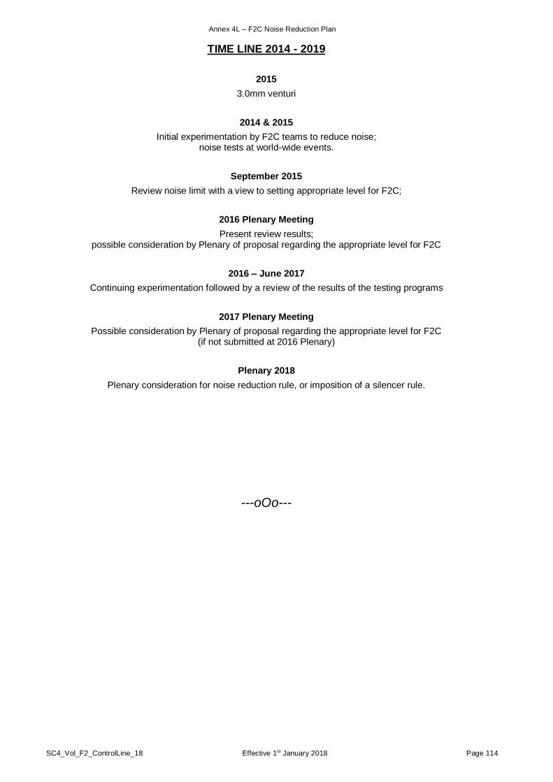
Annex 4L – F2C Noise Reduction Plan
SC4_Vol_F2_ControlLine_18 Effective 1st January 2018 Page 114
TIME LINE 2014 - 2019
2015
3.0mm venturi
2014 & 2015
Initial experimentation by F2C teams to reduce noise; noise tests at world-wide events.
September 2015
Review noise limit with a view to setting appropriate level for F2C;
2016 Plenary Meeting
Present review results; possible consideration by Plenary of proposal regarding the appropriate level for F2C
2016 – June 2017
Continuing experimentation followed by a review of the results of the testing programs
2017 Plenary Meeting
Possible consideration by Plenary of proposal regarding the appropriate level for F2C (if not submitted at 2016 Plenary)
Plenary 2018
Plenary consideration for noise reduction rule, or imposition of a silencer rule.
---oOo---