FAGOR AUTOMATION S · Products manufactured by Fagor Automation S ... application between 0.318 and...
78
FAGOR AUTOMATION S.COOP . Brushless AC servo drives ~ MCSi-C0 series ~ Ref.1504 Original instructions
Transcript of FAGOR AUTOMATION S · Products manufactured by Fagor Automation S ... application between 0.318 and...

FAGOR AUTOMATION S.COOP.
Brushless ACservo drives
~ MCSi-C0 series ~
Ref.1504
Original instructions

Title Brushless AC servo drives. MCSi-C0 series.
Type of documentation Description, installation and startup of motors andMCS INNOVA digital drives with CAN interface.
Name MAN REGUL MCSi‐C0 (IN)
Reference Ref.1504
Software Version 01.0x
Electronic document man_mcsi_c0.pdf
Headquarters FAGOR AUTOMATION S.COOP.B.º San Andrés 19, Apdo. 144E- 20500 ARRASATE- MONDRAGÓ[email protected]
The information described in this manual may be subject to changesdue to technical modifications. FAGOR AUTOMATION S.Coop.reserves the right to change the contents of this manual withoutprior notice.
The contents of this manual have been verified and matched withthe product described here. Even so, it may contain involuntaryerrors that make it impossible to ensure an absolute match. How-ever, the contents of this document are regularly checked andupdated implementing the necessary corrections in a later edition.
All rights reserved. No part of this documentation may be copied,transmitted, transcribed, stored in a backup device or translated intoanother language without Fagor Automation’s permission.
34-943-719200
34-943-771118 (Technical Service Department)
DUAL‐USE products. Products manufactured by Fagor Automation S. Coop. included onthe list of dual‐use products according to regulation (UE) Nr 1382/2014. Their product identification includes the text ‐MDU and requirean export license depending on destination.
2/76 - MCSi-C0 Digital Brushless AC servo drive system - Ref.1504

Warranty
INITIAL WARRANTY
All products manufactured or marketed by FAGOR carry a 12-month warranty for theend user.
In order to prevent the possibility of having the time period from the time a product leaves ourwarehouse until the end user actually receives it run against this 12-month warranty, the OEMor distributor must communicate to FAGOR the destination, identification and installation dateof the machine by filling out the Warranty Form that comes with each product.
The starting date of the warranty for the user will be the one appearing as theinstallation date of the machine on the Warranty Form.
This system ensures the 12-month warranty period for the user.
FAGOR offers a 12-month period for the OEM or distributor for selling and installing theproduct. This means that the warranty starting date may be up to one year after the producthas left our warehouse so long as the warranty control sheet has been sent back to us. Thistranslates into the extension of warranty period to two years since the product left ourwarehouse. If this sheet has not been sent to us, the warranty period ends 15 months fromwhen the product left our warehouse.
FAGOR is committed to repairing or replacing its products from the time when the first suchproduct was launched up to 8 years after such product has disappeared from the product cat-alog.
It is entirely up to FAGOR to determine whether a repair is to be considered under warranty.
EXCLUDING CLAUSES
The repair will take place at our facilities. Therefore, all shipping expenses as well as travel-ling expenses incurred by technical personnel are NOT under warranty even when the unit isunder warranty.
The warranty will be applied so long as the equipment has been installed according to theinstructions, it has not been mistreated or damaged by accident or negligence and has beenhandled by personnel authorized by FAGOR.
If once the service call or repair has been completed, the cause of the failure is not to beblamed on the FAGOR product, the customer must cover all generated expenses accordingto current fees.
No other implicit or explicit warranty is covered and FAGOR AUTOMATION shall not be heldresponsible, under any circumstances, of the damage which could be originated.
SERVICE CONTRACTS
Service and Maintenance Contracts are available for the customer within the warranty periodas well as outside of it.
Digital Brushless AC servo drive system - Ref.1504 MCSi-C0 - 3/76

Declaration of conformity
Manufacturer: Fagor Automation, S. Coop.
B.º San Andrés 19, C.P. 20500, Mondragón - Gipuzkoa - (SPAIN)
We hereby declare, under our responsibility that the product:
FAGOR AC Brushless Servo Drive Systemconsisting of the following modules and motors:
Drives MCS Innova. MCSi-XXX-C0 series.
AC motors FS. FSA and FSP series.
mentioned on this declaration,
with the basic requirements of the European Directives 2006/95/EC on Low Voltage(Basic Safety Regulation; Machinery Electrical Equipment EN 60204-1:2006) and2004/108/EC on Electromagnetic Compatibility (EN 61800-3:2004, Specific Regulationon Electromagnetic Compatibility for Servo Drive System).
In Mondragón, April 1th, 2015
Introduction
FAGOR offers a range of servo systems (AC Brushless motor FS plus digital drive) forapplication between 0.318 and 2.39 N·m at a rated speed of 3000 rev/min.
This manual describes the elements in detail and guides step by step through theinstallation and setup of the drive system.
When installed for the first time, it is a good idea to read the whole document.
Should you have any doubts or questions, please do not hesitate to contact ourtechnicians at any of our subsidiaries worldwide.
Thank you for choosing FAGOR.
4/76 - MCSi-C0 Digital Brushless AC servo drive system - Ref.1504

General index
BRUSHLESS AC MOTORS, FS. . . . . . . . . . . . . . . . . . . . . . . . . . . . . . . 7
Introduction . . . . . . . . . . . . . . . . . . . . . . . . . . . . . . . . . . . . . . . . . . . . . . . 7General characteristics . . . . . . . . . . . . . . . . . . . . . . . . . . . . . . . . . . . . . . 7Synchronous AC servomotors FSP series . . . . . . . . . . . . . . . . . . . . . . . 9Dimensions . . . . . . . . . . . . . . . . . . . . . . . . . . . . . . . . . . . . . . . . . . . . . . 10Power connectors and encoder output . . . . . . . . . . . . . . . . . . . . . . . . . 12Holding brake . . . . . . . . . . . . . . . . . . . . . . . . . . . . . . . . . . . . . . . . . . . . 13Sales model . . . . . . . . . . . . . . . . . . . . . . . . . . . . . . . . . . . . . . . . . . . . . 14
MCSi-C0 SERVODRIVE. . . . . . . . . . . . . . . . . . . . . . . . . . . . . . . . . . . . 15
Introduction . . . . . . . . . . . . . . . . . . . . . . . . . . . . . . . . . . . . . . . . . . . . . . 15General characteristics . . . . . . . . . . . . . . . . . . . . . . . . . . . . . . . . . . . . . 15Dimensions . . . . . . . . . . . . . . . . . . . . . . . . . . . . . . . . . . . . . . . . . . . . . . 15Technical data. . . . . . . . . . . . . . . . . . . . . . . . . . . . . . . . . . . . . . . . . . . . 16Connectors . . . . . . . . . . . . . . . . . . . . . . . . . . . . . . . . . . . . . . . . . . . . . . 16Light indicators . . . . . . . . . . . . . . . . . . . . . . . . . . . . . . . . . . . . . . . . . . . 18Push-buttons and rotary switches . . . . . . . . . . . . . . . . . . . . . . . . . . . . . 19Front view . . . . . . . . . . . . . . . . . . . . . . . . . . . . . . . . . . . . . . . . . . . . . . . 19Top view . . . . . . . . . . . . . . . . . . . . . . . . . . . . . . . . . . . . . . . . . . . . . . . . 20Pinout of the connectors . . . . . . . . . . . . . . . . . . . . . . . . . . . . . . . . . . . . 20Sales model . . . . . . . . . . . . . . . . . . . . . . . . . . . . . . . . . . . . . . . . . . . . . 22
INSTALLATION . . . . . . . . . . . . . . . . . . . . . . . . . . . . . . . . . . . . . . . . . . 23
General considerations . . . . . . . . . . . . . . . . . . . . . . . . . . . . . . . . . . . . . 23Electrical connections . . . . . . . . . . . . . . . . . . . . . . . . . . . . . . . . . . . . . . 24Electrical cabinet . . . . . . . . . . . . . . . . . . . . . . . . . . . . . . . . . . . . . . . . . . 36Safety Disable . . . . . . . . . . . . . . . . . . . . . . . . . . . . . . . . . . . . . . . . . . . . 37Initialization and adjustment . . . . . . . . . . . . . . . . . . . . . . . . . . . . . . . . . 39Standard CAN parameter setting . . . . . . . . . . . . . . . . . . . . . . . . . . . . . 40Speed selection and node number . . . . . . . . . . . . . . . . . . . . . . . . . . . . 43WinDDSSetup . . . . . . . . . . . . . . . . . . . . . . . . . . . . . . . . . . . . . . . . . . . . 48
PARAMETERS, VARIABLES & COMMANDS . . . . . . . . . . . . . . . . . . 50
Unit interpretation . . . . . . . . . . . . . . . . . . . . . . . . . . . . . . . . . . . . . . . . . 50Notation used and definition of groups . . . . . . . . . . . . . . . . . . . . . . . . . 50
Digital Brushless AC servo drive system - Ref.1504 MCSi-C0 - 5/76

Handling internal variables . . . . . . . . . . . . . . . . . . . . . . . . . . . . . . . . . . 52B group. Non-programmable inputs-outputs . . . . . . . . . . . . . . . . . . . . 53C group. Current . . . . . . . . . . . . . . . . . . . . . . . . . . . . . . . . . . . . . . . . . 53D group. Diagnosis . . . . . . . . . . . . . . . . . . . . . . . . . . . . . . . . . . . . . . . 55G group. General . . . . . . . . . . . . . . . . . . . . . . . . . . . . . . . . . . . . . . . . . 57H group. Hardware. . . . . . . . . . . . . . . . . . . . . . . . . . . . . . . . . . . . . . . . 58I group. Inputs . . . . . . . . . . . . . . . . . . . . . . . . . . . . . . . . . . . . . . . . . . 58K group. Monitoring . . . . . . . . . . . . . . . . . . . . . . . . . . . . . . . . . . . . . . . 59M group. Motor . . . . . . . . . . . . . . . . . . . . . . . . . . . . . . . . . . . . . . . . . . . 60N group. Mechanical . . . . . . . . . . . . . . . . . . . . . . . . . . . . . . . . . . . . . . 60O group. Analog and digital outputs. . . . . . . . . . . . . . . . . . . . . . . . . . . 61P group. Position loop . . . . . . . . . . . . . . . . . . . . . . . . . . . . . . . . . . . . . 61Q group. Communication . . . . . . . . . . . . . . . . . . . . . . . . . . . . . . . . . . . 62S group. Speed . . . . . . . . . . . . . . . . . . . . . . . . . . . . . . . . . . . . . . . . . . 63T group. Torque and power . . . . . . . . . . . . . . . . . . . . . . . . . . . . . . . . . 66
ERROR CODES . . . . . . . . . . . . . . . . . . . . . . . . . . . . . . . . . . . . . . . . . . 67
LIST OF PARAMETERS, VARIABLES & COMMANDS. CAN ID´s. . . . . . . . . . . . . . . . . . . . . . . . . . . . . . . . . . . . . . . . . . . . . . . . 72
6/76 - MCSi-C0 Digital Brushless AC servo drive system - Ref.1504

BRUSHLESS AC MOTORS, FS
Introduction
General characteristics
TABLE 1. General characteristics of FS motors.
Excitation Permanent magnets
Temperature sensor Not available
Shaft end Cylindrical with keyway (optional: without keyway)
Mounting Face flange
Mounting method IM B5, IM V1, IM V3 (as per IEC-34-3-72)
Mechanical tolerancesEccentricity: 0.02 Concentricity: 0.04Perpendicularity: 0.04
Roller bearings’ life 20000 hours
Vibration resistance Vibration acceleration: 49 m/s²
Vibration class 15 µm or lower
Electrical insulation Class B (130 °C / 266 °F)
Insulation resistance 500 V DC, 10 M or greater
Dielectric rigidity 200 V motors: 1500 V AC, one minute
Body or housing Totally enclosed and self-ventilated
Protection degree General: standard IP 55 (shaft section excluded)
Storage temperature From - 20 °C to 60 °C (- 4 °F to 140 °F)
Ambient temperature allowed From 0 °C to 40 °C (32 °F to 104 °F)
Working ambient humidity From 20 % to 80 % (non condensing)
Voltage supply for the brake 24 V DC - the brake is optional -
Feedback Standard: Incremental encoder 13 bits: 2048 pptOptional: Absolute encoder 16 bits: 16384 ppt
FS synchronous servo motors - FSA and FSP series - are AC Brushless with permanent mag-nets.They are ideal for any applicationrequiring great positioning accuracy.
They have a uniform output torque,high reliability and low maintenance.
Digital Brushless AC servo drive system - Ref.1504 MCSi-C0 - 7/76

8/76 - MCSi-C0 Digital Brushless AC servo drive system - Ref.1504
TABLE 2.
Charac
teristics table of non‐ventilated FSA and FSP m
oto
rs w
ith “F” w
inding ( 220 V AC).
FS
A S
ER
IES
Stall torque
Stall peak torque
Rated speed
Maximumspeed
Stall current
Peak current
Power
Torque constant
Acceleration time
Inertia 1]
Mass 2]
Pea
k to
rque
(for
3 s
econ
ds)
Mo
Nm
Mp
Nm
nN
rev/
min
nmax
rev/
min
Io
Arm
s
Ip
Arm
s
P W
Kt
Nm
/Arm
s
tac
ms
J
kg·c
m2
M kg
MC
Si
-07L
-C0
Nm
MC
Si
-11L
-C0
Nm
MC
Si
-15L
-C0
Nm
FS
A0
1.50
F.
.
0.3
180
.95
300
050
000.
92.
810
00.
378
1.1
90.
036
0.5
0.9
5
FS
A0
2.50
F.
.
0.6
371
.91
300
050
002.
16.
520
00.
327
1.7
40.
106
1.1
1.9
1
FS
A0
4.50
F.
.
1.2
703
.82
300
050
002.
88.
540
00.
498
1.4
20.
173
1.7
3.2
43.
82
FS
A0
8.50
F.
.
2.3
907
.16
300
050
004.
413
.475
00.
590
2.9
50.
672
3.4
3.8
46.
197.
16
FS
P S
ER
IES
Stall torque
Stall peak torque
Rated speed
Maximumspeed
Stall current
Peak current
Power
Torque constant
Acceleration time
Inertia 1]
Mass 2]
Pea
k to
rque
(for
3 s
econ
ds)
Mo
Nm
Mp
Nm
nN
rev/
min
nmax
rev/
min
Io
Arm
s
Ip
Arm
s
Pow kW
Kt
Nm
/Arm
s
tac
ms
J
kg·c
m2
M kg
MC
Si
-07L
-C0
Nm
MC
Si
-11L
-C0
Nm
MC
Si
-15L
-C0
Nm
FS
P0
1.50
F.
.
0.3
180
.95
3.00
05
.000
0.9
2.8
100
0.39
21
.62
0.49
10.
70
.95
FS
P0
2.50
F.
.
0.6
371
.91
3.00
05
.000
2.0
6.0
200
0.34
93
.17
0.19
31.
41
.91
FS
P0
4.50
F.
.
1.2
703
.82
3.00
05
.000
2.6
8.0
400
0.53
52
.72
0.33
12.
13
.48
3.82
FS
P0
8.50
F.
.
2.3
907
.16
3.00
05
.000
4.1
13.9
750
0.64
19
.21
2.10
04.
24
.17
6.73
7.16
1 If the m
oto
r has a brake (option), its inertia m
ust also be tak
en in
to account. See «brake charac
teristics».
2 If the m
oto
r has a brake (option), its mas
s must also be tak
en in
to account. See «brake charac
teristics».
Note. T
he drive reco
mmended to gove
rn eac
h m
oto
r must supply the rated current needed to obtain the rated torq
ue fro
m the m
oto
r.

Torque-speed curves
Synchronous AC servomotors FSA series
Synchronous AC servomotors FSP series
1000 3000 5000
0.2
TorqueNm
Speed Rev/min2000 40000
0
0.4
0.6
0.8
1.0
1.2
0.318
0.95
0.2
1000 3000 5000
TorqueNm
Speed Rev/min2000 40000
0
1.0
1.5
2.0
2.5
3.0
0.637
1.91
0.5 0.450.36
FSA01FSA02
1000 3000 5000
TorqueNm
Speed Rev/min2000 40000
0
2.0
3.0
4.0
5.0
1.27
3.82
1.0 0.960.75
1.6
3.0
FSA04
1000 3000 5000
TorqueNm
Speed Rev/min2000 40000
0
4.0
6.0
8.0
10.0
2.39
7.16
2.0 1.81.5
5.6
FSA08
1000 3000 5000
TorqueNm
Speed Rev/min2000 40000
0
4.0
6.0
8.0
10.0
2.39
7.16
2.01.0
1000 3000 5000
TorqueNm
Speed Rev/min2000 40000
0
2.0
3.0
4.0
5.0
1.27
3.82
1.0 0.960.75
1.6
3.0
1000 3000 5000
TorqueNm
Speed Rev/min2000 40000
0
1.0
1.5
2.0
2.5
3.0
0.637
1.91
0.50.3
1000 3000 5000
0.2
TorqueNm
Speed Rev/min2000 40000
0
0.4
0.6
0.8
1.0
1.2
0.318
0.82
0.15
0.95
FSP01FSP02
FSP04 FSP08
Digital Brushless AC servo drive system - Ref.1504 MCSi-C0 - 9/76

Dimensions
Synchronous AC servomotors. FSA series
FIGURE 1.
Dimensions of FSA series synchronous servo motors.
TABLE 3. Motor. Dimensions in mm.
Dimensions Motor length Flange surface
Motor type LM L LL brake LR LA LB LC LE LG LZ
FSA01 61.5 119.5 94.5 40.5 25 46 30h 40 2.5 5 4.3
FSA02 63.0 126.5 96.5 39.5 30 70 50h 60 3 6 5.5
FSA04 91.0 154.5 124.5 39.5 30 70 50h 60 3 6 5.5
FSA08 111.5 185.0 145.0 44.5 40 90 70h 80 3 8 7.0
The brake column shows the length increment for the L and LL measurements whenusing a motor configuration «with brake».
TABLE 4. Shaft. Dimensions in mm.
Dimensions Shaft end Shaft hole
Motor type S QK W T V
FSA01 8h6 14 3 3 9,2 M3 x 6
FSA02 14h6 20 5 5 16 M5 x 8
FSA04 14h6 20 5 5 16 M5 x 8
FSA08 16h6 30 5 5 18 M5 x 8
10/76 - MCSi-C0 Digital Brushless AC servo drive system - Ref.1504

Synchronous AC servomotors. FSP series
FIGURE 2.
Dimensions of FSP series synchronous servo motors.
TABLE 5. Motor. Dimensions in mm.
Dimensions Motor length Flange surface
Motor type LM L LL brake LR LA LB LC LE LG LZ
FSP01 42.5 87 62 29.0 25 70 50h7 60 3 6 5.5
FSP02 48.1 97 67 31.5 30 90 70h7 80 3 8 7
FSP04 68.1 117 87 31.5 30 90 70h7 80 3 8 7
FSP08 66.7 126.5 86.5 33.5 40 14 110h 12 3.5 10 10
The brake column shows the length increment for the L and LL measurements whenusing a motor configuration «with brake».
TABLE 6. Shaft. Dimensions in mm.
Dimensions Shaft end Shaft hole
Motor type S QK W T V
FSP01 8h6 14 3 3 9.2 M3x6
FSP02 14h6 16 5 5 16 M5x8
FSP04 14h6 16 5 5 16 M5x8
FSP08 16h6 22 5 5 18 M5x8
Digital Brushless AC servo drive system - Ref.1504 MCSi-C0 - 11/76

Power connectors and encoder output
The following figure shows the identification of these connectors:
Note that although the figure shows the FSA series motor, the dimensions of all theconnectors will be the same for the FSP series.
The base power connector includes pins 4 and 5 of the brake. Remember that it has nopolarity and, therefore, the 24 V DC may be applied to either pin. A voltage between 22and 26 V DC applied to the brake releases the shaft .
When installing the motor, verify that the brake releases the shaft completely beforeturning it for the first time.
Connecting the motor windings in the order indicated on the connector (U, V, W) of thefigure below, the shaft will turn clockwise (CWR, clockwise rotation).
FIGURE 3.
Power and feedback connector.
FIGURE 4.
Power base connector pinout.
2
1
2
1
12
Nr ConnectorBase power connector Base feedback connector
BASE POWER CONNECTOR
On FSA and FSP motors (200 V)
* No polarity
Signal
2
16
5
4 3
Pin Color
1 U phase Red
2 W phase White3 V phase Blue4 brake * Black
5 brake * Black
6 Ground Green / Yellow
Viewed from the outside of the motor
12/76 - MCSi-C0 Digital Brushless AC servo drive system - Ref.1504

Holding brake
FSA and FSP series motors have an optional brake that applies friction to the shaft. Itspurpose is to immobilize or lock vertical axes, not to brake a moving axis.
Its main characteristics depending on the type of brake are:
FIGURE 5.
Feedback base connector pinout.
WARNING. NEVER use this brake to stop a moving axis !
TABLE 7. Technical characteristics of the brake.
Brake Holding torque Power consumption
Supply voltage
Inertia Mass
N·m (lbf·in) W (hp) V DC kg·cm² kg (lbf)
FSA01 0.318 (2.814) 6.0 (0.008) 24 0.0085 0.300 (0.66)
FSA02 0.637 (5.637) 6.9 (0.009) 24 0.058 0.500 (1.10)
FSA04 1.270 (11.240) 6.9 (0.009) 24 0.058 0.500 (1.10)
FSA08 2.390 (21.153) 7.7 (0.010) 24 0.058 0.900 (1.98)
FSP01 0.318 (2.814) 8.1 (0.010) 24 0.029 0.200 (0.44)
FSP02 0.637 (5.637) 7.6 (0.010) 24 0.109 0.500 (1.10)
FSP04 1.270 (11.240) 7.6 (0.010) 24 0.109 0.500 (1.10)
FSP08 2.390 (21.153) 7.5 (0.010) 24 0.875 1.500 (33.1)
WARNING.
The brake must never exceed its maximum turning speed. A voltage between 22 V DC and 26 V DC releases the shaft from being
locked up. Make sure that no voltage over 26 V DC is applied that preventsthe shaft from turning.
When installing the motor, make sure that the brake fully releases the shaftbefore making it turn for the first time.
1
2
3
4
567
8
9
1011
12
13
14
15
1617
BASE FEEDBACK CONNECTOR
On FSA and FSP motors (200 V)
Note 1. The rest of pins are not connected
SignalPin Color
1 0 V (16 bit absolute) Pink
2 3.6 V (16 bit absolute) Grey3 + RS485 Green4 - RS485 Yellow
8 + 5 V White
9 0 V Brown
Note 2. Connector housing connected to ground
Viewed from the outside of the motor
Digital Brushless AC servo drive system - Ref.1504 MCSi-C0 - 13/76

Sales model
FIGURE 6.
Sales model of FS series axis feed motors.
MOTOR LENGTH
MOTOR SERIES
LONG MOTORS SHORT MOTORS
MAXIMUM SPEED
Note that the rated speed is 3000 rev/min
50 5000 rev/min
VOLTAGE400 V A200 V F
SIZE/POWER
HEIGHT
FEEDBACK
13 bit incremental J516 bit absolute J7
FLANGE & SHAFT
Cylindrical shaft with keyway and tapped hole Cylindrical keyless shaft and tapped hole
BRAKE/SEAL OPTION
Without brake or seal (no considered) With brake (24 V DC), without seal With brake (24 V DC), with seal Without brake, with seal
CONNECTION
Interconnectron connector
0 1 2 3
0 1
0
SPECIAL CONFIGURATION S
ESPECIFICATION
only when having the special "S" configuration !
01 ZZ
A
P
200 V kW
04 0.4
60
200 V kW
02 0.280
04 0.4
08 0.75
08 0.75120
FSA04.50F.J5.000 - S99
FSA FSP
40 01 0.1
02 0.2
01 0.1
14/76 - MCSi-C0 Digital Brushless AC servo drive system - Ref.1504

MCSI-C0 SERVODRIVEIntroduction
The MCS innova servo drive (MCSi) family is a compact speed servo drive family forcontrolling small synchronous AC brushless motors. There are three modules of differ-ent power offering peak currents of 6.5, 10.5 and 15.0 Arms for single-phase 220 V AC.
General characteristics
Their main characteristics are:
Dimensions
220 V AC single-phase voltage supply. Dynamic braking in case of mains failure. PWM IGBTs. Serial encoder feedback. CAN based field bus communication interface. USB service communication line. Two logic inputs to control the motor: Speed Enable and Drive Enable. CANopen® communication protocol.
FIGURE 7.
Dimensions of the MCSi‐L‐C0 drives.
81 mm (3.18")
18
0.6
mm
(
7.1
1")
19
3.6
mm
(7
.62
")
183 mm (7.20")
16
3.6
mm
(
6.4
4")
A
Models: MCSi-07L-C0MCSi-11L-C0
6.30 mm (0.24")
6.5
0 m
m (
0.2
5")
detail A
Model:
MCSi-15L-C0183 mm (7.20")
16
3.6
mm
(
6.4
4")
101 mm (3.97")
18
0.6
mm
(
7.1
1")
19
3.6
mm
(
7.6
2")
6.30 mm (0.24")
6.5
0 m
m (
0.2
5")
detail A
A
Digital Brushless AC servo drive system - Ref.1504 MCSi-C0 - 15/76

Technical data
Connectors
Power terminals
CONNECTOR X4
POWER INPUTS L1, L2. Mains input terminals.
POWER OUTPUTS U, V, W. Output terminals for the voltage applied to the motor. Cur-rent control with PWM on a carrier frequency of 8 kHz. When connecting to the motor,watch the matching of phases U-U, V-V and W-W.
CONNECTOR X9
L+, Ri, Re. Terminals to configure and connect the external ballast resistor.
CONNECTOR X5
CONTROL POWER INPUTS L1, L2, GROUND. Input terminals for the voltage supplyof the drive's control circuits from mains. The maximum cable section at these powerterminals is 2.5 mm².
TABLE 8. Technical data.
MODELSMCSi 07L MCSi 11L MCSi 15L
Rated output current 2.1 Arms 3.5 Arms 5.0 Arms
Peak current (3 s) 6.5 Arms 10.5 Arms 15.0 Arms
Power supplySingle phase 50/60 Hz.
Voltage range between 220-10 % and 230+10 % V AC
Consumption 12.5 Arms 20.0 Arms 29.0 Arms
Over‐voltage protection 390 V DCFrequency Lower than 600 Hz
Internal Ballast resistor - - 45 Internal Ballast power - - 15 W
Ballast trigger 380 V DC
Thermal protection of the heatsink 90 °C (194 °F)
Operating temperature 5 °C / 45 °C (41 °F / 113 °F)Storage temperature - 20 °C / 60 °C (- 4 °F / 140 °F)
Protection degree * IP 20 IP 20 IP 20
Module dimensions81x163.6x183 mm(3.18x6.44x7.20 “)
101x163.6x183 mm(3.97x6.44x7.20 “)
Module mass 1.9 kg (4.18 lb) 2.1 kg (4.62 lb)
* IP 20 means that it is protected against objects of a diameter larger than 12.5 mm, but not againstwater splashes. Therefore, the unit must be mounted inside an electrical cabinet.
16/76 - MCSi-C0 Digital Brushless AC servo drive system - Ref.1504

ACTIVATION OF THE INTERNAL FAN. The internal fan that cools the drive's powerelements starts when enabling the Drive Enable signal. The fan will stop when the heat-sink temperature is lower 70 °C since the Drive Enable signal is turned off. This methoddecreases the fan's operating time, thus increasing its useful life.
Control signals
CONNECTOR X3
Drive Enable input, pin 13. No current circulates through the motor stator winding at0 V DC, thus it no longer supplies torque. It is activated with +24 V DC.
Speed Enable input, pin 15. At 0 V DC, it forces an internal zero velocity command.It is activated with +24 V DC.
Common to inputs Drive Enable and Speed Enable, pin 14. Reference point forinputs Drive Enable and Speed Enable.
+24 V DC and 0 V DC, pins 43 and 44. Output of the internal 24 V DC power supplythat may be used for the control of inputs Drive Enable and Speed Enable as well as theprogrammable digital input. It offers a maximum current of 50 mA limited internally.
Programmable digital input, pins 11 and 12. Digital input (servo drive at +24 V DCand 0 V DC).
Programmable digital output, pins 27 and 28. Opto-coupled open collector output.
Drive Ok, pins 29 and 30. Relay contact that closes when the internal status of thedrive control is OK.
Safe-disable relay, pins 41 and 42. Second, normally closed contact (NC) used as anexternal acknowledgement of the status of the safety relay.
ENABLES
pin 13 Drive Enable
pin 15 Speed Enable
pin 14 Pin common to inputs Drive Enable and Speed Enable
pin 43 +24 V DC of the auxiliary power supply ( max. 50 mA)pin 44 GND of the auxiliary 24 V DC power supply
DIGITAL INPUTS AND OUTPUTS
DRIVE OK.
Note. Remember that this relay contact must be necessarily included in the electricalmaneuver.
RELAY FOR SAFETY
Note. Remember that this relay contact must be necessarily included in the electricalmaneuver.
Digital Brushless AC servo drive system - Ref.1504 MCSi-C0 - 17/76

Metal housing of the connector. Drive chassis connection point.
CONNECTOR X2
MOTOR FEEDBACK INPUT (feedback Input)
Standard IEEE 1394 type connector for input of the serial encoder signals, installed onthe motor itself for position + speed feedback.
CONNECTOR X6
SERVICE
Standard USB mini AB type connector for connecting to a PC and updating the firm-ware. Any standard USB cable with a miniA or miniB connector may be connected atthe drive side.
CONNECTOR X8
CAN FIELD BUS (meets DS-301 standard regarding communications).
«Open Style» 5-pin female connector of the CAN communication board that may beused to connect the drive modules of the system with the CNC that governs them. Theconnection is made through CAN cable and it has a bus type structure. It comes withtwo rotary switches and two status-indicating LED's (Light Emitting Diodes).
Light indicators
+5 V. LED located on top of connector X1. When lit, it indicates that the internal +5V arebeing applied.
CROWBAR VBUS OK. Two-color (green/red) light indicator located next to the +5VLED. It indicates its status according to the following table:
Module Status & Network Status. Indicator lights on top of the X1 connector abovethe two rotary «Node Select» selectors. It has several lighting sequences that indicatethe status of both the CAN bus and the drive. For further detail, see section ‐ Initial‐ization and adjustment ‐ of this manual.
Numerical displays. It has four 7-segment numerical displays and a sign light to dis-play the drive status.
CHASSIS
FIGURE 8.
“CROWBAR VBUS OK” LED states.
«CROWBAR VBUS OK» LED states
OFF No voltage in the power circuit.
ON «green» With voltafe in the power circuit.
ON «red»
The voltage of the internal bus hasexceeded the preset voltage valuesand the Ballast resistor has beenactivated.
18/76 - MCSi-C0 Digital Brushless AC servo drive system - Ref.1504

Push-buttons and rotary switches
RESET: Push-button for resetting the system.
NODE SELECT: Consisting in two rotary switches used to determine the node numberassigned to the drive in the CAN bus and also select the communication speed of thebus. For further detail, see section ‐ Initialization and adjustment ‐ of this manual.
Front view
FIGURE 9.
Front view of the module.
Four 7‐segments displays
Sign indicating display
Input terminals for the voltage supplyof the control circuits from mains(single phase, 220 V AC)
Mains input terminals for the modulevoltage supply (single phase 220 V AC)and voltage output terminal to themotor (three‐phase 220 V AC)
Control signal connector
Encoder signal input connector
LED's indicating that there is voltage atthe bus, that the crowbar is activatedand that there is internal voltage.
Reset button
Node selectors
Light indicators for CAN busstatus and drive status
RS‐485 serial line connector *
* Connector X1 is not operative in this versionNote.
Digital Brushless AC servo drive system - Ref.1504 MCSi-C0 - 19/76

Top view
Pinout of the connectors
FIGURE 10.
Top view of the module.
Connector (X9) to configureand connect the externalBallast resistor
USB mini connector(X6) type A or B toconnect to a PC
Connector (X8) for CANconnection with the CNC andother modules
FEEDBACK INPUT (X2)
Pin Signal Description
1 + 5 V Voltage supply for the encoder
2 GND Encoder voltage supply GND
3 + BAT + battery (with absolute encoder)
4 - BAT - Battery (with absolute encoder)
5 + 485 Encoder communication
6 - 485 Encoder communication
Chassis Connector housing
20/76 - MCSi-C0 Digital Brushless AC servo drive system - Ref.1504

CONTROL SIGNALS (X3)
Pin Signal I/O Description
34AUX. ±12 V O
+12 V (20 mA max) output
33 -12 V (20 mA max) output
19 GND
43AUX 24 V DC O
+24 V DC (50 mA max) output
44 GND AUX 24 V DC
13 DRIVE ENABLE I DRIVE ENABLE input (range from 0 to 24V DC)
15 SPEED ENABLE I SPEED ENABLE input (range from 0 to 24V DC)
14 COMMON DRIVE - Common to inputs DRIVE ENABLE and SPEED ENABLE
11PROG. DIGIT. INPUT I
Programmable digital input +Range from 0 to 24 V DC
12 Common of the digital input -
27 PROG. DIGIT. OUTPUT
OProgrammable digital output (collector)
100 mA max, 50 V DC28 Programmable digital output (emitter)
29DRIVE OK O
Open contact of the DRIVE OK signal(0.6 A - 125 V DC, 0.5 A - 110 V DC, 2 A - 30 V DC)30
41SAFETY RELAY O
Second contact (NC normally closed) used as external acknowledgmentof the status of the integrated safety relay.42
Out of the 44 pins of the connector, those not identified in this table are NC pins (Not Connected).The < I/O > column indicates whether it is an input signal (Input) or an output signal (Output) through the relevantpin at connector X3.
POWER INPUTS & MOTOR (X4)
CONTROL POWER INPUTS (X5)
Pin Signal Description
L2 S phase 220 V mains voltage input terminals.L1 R phase
W W phase Output terminals for the voltage applied to the motor (200 V).
V V phase
U U phase
Pin Signal Description
L2 S phase 220 V mains input terminal for the control circuits.L1 R phase
Ground Chassis Ground
Digital Brushless AC servo drive system - Ref.1504 MCSi-C0 - 21/76

Sales model
Sales model codes for MCS innova drives with CAN communication bus (meets CANo-pen® standard at DS-301 communication level).
SERVICE (X6)
Pin Signal Description
1 N.C. Not connected
2 DMO DMO
3 DPO DPO
4 N.C. Not connected
5 GND GND
Chassis Housing
CAN (X8)
Pin Signal Description
1 GNDa (N.C.) Not Connected
2 CANL CAN_L bus line (low dominant)
3 SHIELD CAN cable shield
4 CANH CAN_H bus line (high dominant)
5 SHIELD (N.C.) Not Connected
54321
MCS INNOVA DIGITAL DRIVE
Model
Current (A)
Power Supply 220 V AC
MCS Innova
Rated Peak (3 s)
2.1 6.5
10.5
15.0
3.5
5.0
EXAMPLE. MCSi - 07 L - C0
07
11
15
With CAN board
22/76 - MCSi-C0 Digital Brushless AC servo drive system - Ref.1504

INSTALLATIONGeneral considerationsAt the motorRemove the anti-corrosion paint of the rotor and of the flange before installing themotor on the machine. The motor may be mounted as IM B5 and IM V1.
Watch for the ambient conditions mentioned in the section on «technical data» and also:
Mount it somewhere that is dry, clean and accessible for maintenance.
It must be easily cooled.
Avoid corrosive or flammable environments.
Guard the motor with a cover if it is exposed to splashes.
Use flexible coupling for direct transmission.
Avoid radial and axial loads on the motor shaft.
At the drive
The module must be installed in an electrical cabinet that is clean, dry, free of dust, oiland other pollutants. Remember that its degree of protection is IP 20.
Never install it exposing it to flammable gases. Avoid excessive heat and humidity. Theambient temperature must never exceed 45 °C (113 °F). Install the modules vertically,avoid vibrations and respect the gaps to allow air flow. See figure.
Note. The degree of protection is IP 55 (standard), shaft section excluded.
MANDATORY. DO NOT hit the shaft when installing transmission pulleys or gears!
Use some tool that is supported in the threadedhole on the shaft to insert the pulley or the gear.
FIGURE 11.
Module installing method.
M6
M6
> 50 mm
> 50 mm> 10 mm
> 30 mm
Digital Brushless AC servo drive system - Ref.1504 MCSi-C0 - 23/76

About the connectionAll the cables must be shielded, to reduce the interference on the control of the motordue to the commutation of the PWM. The shield of the motor power cable must be con-nected to the chassis screw at the bottom of the module and it, in turn, taken to mainsground. The command signal lines must be shielded twisted pairs. The shield must beconnected to the housing of connector X3.
Electrical connections
Basic interconnection diagram
Power connection. Mains-drive
The drive is powered with single-phase 220 V AC.
Note. Keep the signal cables away from the power cables.
FIGURE 12.
Basic module interconnection diagram.
FIGURE 13.
Mains power connection of the drive, with transformer.
External Ballast resistor (optional)
MC
Si-X
XL-
C0
Feedback Cable AESC-MMains
Mains FS
A o
r F
SP
SE
RV
O M
OT
OR
Power Cable MPC
(with absolute encoder)
X5
L2L1
L2L1
X4
220 V ACR
S
T
N
380 V AC
CO
NT
RO
LP
OW
ER
IN
PU
TP
OW
ER
IN
PU
TS
X5
L2L1
L2L1
X4
220 V AC
220 V AC
R
S
T
N
380 V AC
High FloatingVoltage
CO
NT
RO
LP
OW
ER
IN
PU
TP
OW
ER
IN
PU
TS
220 V AC
Autotransformer orsingle-phase transformer
Autotransformer orsingle-phase transformer
Warning. Never make this connection because there is a risk of destroying the module.
- KM1 power switch
fuses
2x2.5 mm2
fuses
2x2.5 mm2
- KM1 power switch
24/76 - MCSi-C0 Digital Brushless AC servo drive system - Ref.1504

The table below shows the values recommended for the fuses shown in the previousfigure. They are slow general purpose fuses. If they are installed on the mains inputlines, their maximum currents will depend on the value of the mains voltage.
Power connection. External Ballast resistor
If the application requires a Ballast resistor with a power greater than the one indicatedin this table according to model:
therefore:
Remove the cable joining the terminals Ri and L+.
Install the external resistor between the terminals Re and L+.
Note. It is required to install a transformer.
FIGURE 14.
Mains power connection of the drive, without transformer.
TABLE 9. Fuses
Model Peak current ( Arms ) Fuse (A)
MCSi-07L-C0 6.5 16
MCSi-11L-C0 10.5 16
MCSi-15L-C0 15.0 25
Note. A thermal switch may optionally replace the fuses.
TABLE 10. Ballast resistor.
Model Internalresistor Ri
Max. power that may be dissipated in Ri
Externalresistor
MCSi-07L-C0 - - -Max. value 65 Min. value 45 MCSi-11L-C0 - - -
MCSi-15L-C0 45 60 W 15 W
X5
L2L1
L2L1
X4
220 V ACR
S
T
N
380 V AC
CO
NT
RO
LP
OW
ER
IN
PU
TP
OW
ER
IN
PU
TS
X5
L2L1
L2L1
X4
220 V AC
220 V AC
R
S
T
N
380 V AC
380 V AC
CO
NT
RO
LP
OW
ER
IN
PU
TP
OW
ER
IN
PU
TS
220 V AC
Warning. Never make this connection because there is a risk of destroying the module.
2x2.5 mm2 2x2.5 mm2
fuses
fuses
- KM1 power switch
- KM1 power switch
Digital Brushless AC servo drive system - Ref.1504 MCSi-C0 - 25/76

Make sure that the resistance (ohms) of the external ballast resistor is the same asthat of the internal resistor of that module. See TABLE 8.
Use KV41 to indicate to the drive that an external ballast resistor has been con-nected.
Power connection. Inductance for reducing high frequency harmonics
It is recommended to connect an inductance at the input of one of the power phasesL1 or L2 of the drive (connector X4) to reduce high frequency harmonics comingfrom mains with a value of 5 mH and and rms current of 6 Arms. This inductancereduces the disturbances in mains, but it does not ensure compliance with EC regu-lations. See FIGURE 16.
Power connection. Mains filter to suppress electromagnetic interference
In order for the FAGOR DDS system to meet the European Directive on Electromag-netic Compatibility 2004/108/EC, the mains filter FAGOR FEHV-XXX must be inserted(see the table in the next section connection) at the input of the MCSi (power phases L1and L2 of connector X4) against electromagnetic interference.
CONNECTION
Install the proper filter that can handle the sum of the rated Arms currents of the MCSidrives installed in the system.
FIGURE 15.
Power connection for the external Ballast resistor.
Mains filters Imax (A)
FEHV-10Z 10
FEHV-16Z 16
FEHV-30B 30
Note. Remember that the rated currents of the drives are 2.1 A for the MCSi-07L-C0;3.5 A for the MCSi-11L-C0 and 5 A for the MCSi-15L-C0.
L+
Re
Ri
2.5 mm2L+
Re
Ri
MCSi-XXL-C0 DRIVE
InternalBallast
MCSi-XXL-C0 DRIVE
X9 X9External Ballast
X9. Connector on top of the drive module
Re
Ri
L+
X9
26/76 - MCSi-C0 Digital Brushless AC servo drive system - Ref.1504

Connect the filter using 6.3 mm Faston terminals as shown in the figure.
DIMENSIONS
FIGURE 16.
Power connection. Choque and mains filter.
FIGURE 17.
Dimensions of the mains filter FAGOR FEHV‐30B.
L1
L2
Inductance(5 mH, 6 Arms)
X4
220 V ACSINGLE-PHASEMAINS FILTER"FAGOR FEHV-XX"
MCSi-XXL-C0
Mains filters FAGOR FEHV- 30B
Digital Brushless AC servo drive system - Ref.1504 MCSi-C0 - 27/76
Power connection. Drive-motor
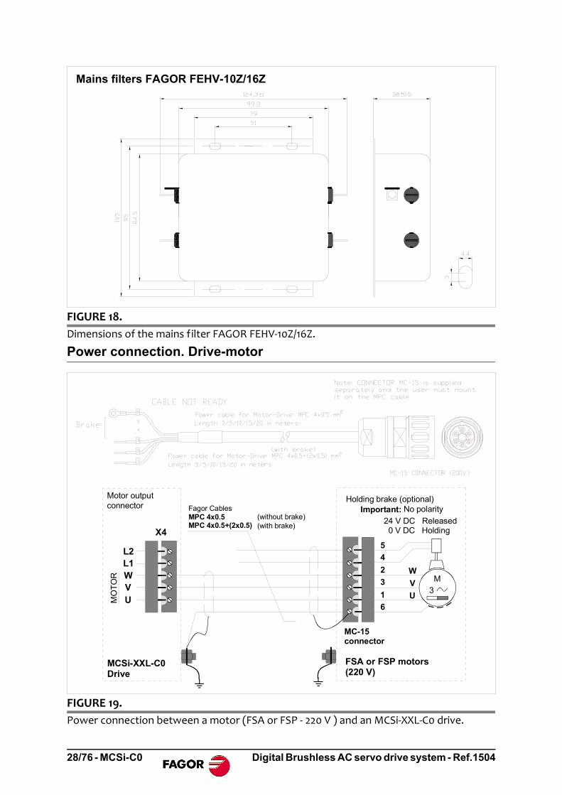
FIGURE 18.
Dimensions of the mains filter FAGOR FEHV‐10Z/16Z.
FIGURE 19.
Power connection between a motor (FSA or FSP ‐ 220 V ) and an MCSi‐XXL‐C0 drive.
Mains filters FAGOR FEHV-10Z/16Z
Fagor CablesMPC 4x0.5MPC 4x0.5+(2x0.5)
M3
Holding brake (optional)
24 V DC Released 0 V DC Holding
U
W
V
X4
MCSi-XXL-C0 Drive
MO
TO
R
FSA or FSP motors(220 V)
Important: No polarity
Motor outputconnector
(with brake)(without brake)
MC-15connector
L2L1WVU
5
4
2
3
1
6
28/76 - MCSi-C0 Digital Brushless AC servo drive system - Ref.1504

POWER CABLES
The code of the sales model of FAGOR power cables is:
Connection of the monitoring and control signals
Enable signals using 24 V.
TABLE 11. Power cables.
For motors without brake For motors with brakeMPC-4x0.5 MPC-4x0.5+ (2x0.5)
Note. The length of the MPC power cable must be specifically ordered (in meters).
FIGURE 20.
Sales model of FAGOR power cables.
FIGURE 21.
Enable signals using 24 V.
MOTOR POWER CABLE
Nr of wires
Motor Power Cable
E.G. MPC 4 x 0.5
Section of each wire (mm2)
E.G. MPC 4 x 0.5 + (2 x 1)
On brakeless motors
On motors with brakeNr of wiresSection of each wire (mm2)
Nr of wires x section (for the brake)
SignalPin
43 24 VGND
13 DRIVE ENABLECOMMON
SPEED ENABLE
44
14
15
44
43131415
X3
44
43
14
15
13
Digital Brushless AC servo drive system - Ref.1504 MCSi-C0 - 29/76

Signal indicating that the drive is running properly
Enable signals
Programmable digital outputs
FIGURE 22.
Signal indicating that the drive is running properly.
FIGURE 23.
Enable signals.
FIGURE 24.
Programmable digital outputs.
X3
3029
DRIVE OK SWITCH 2930
X3TO THE SAFETY CHAIN
0.6 A - 125 V AC
0.6 A - 110 V DC
2 A - 30 V DC SignalPin
29DRIVE OK
30
X3
15
13
131415
X3
+ 24 V
14
0 V
SignalPin
13 DRIVE ENABLE
14
15
COMMON
SPEED ENABLE
X3
28
27
+ 24 V DC
Collector
Emitter
28
X3
X3
28
27
+ 24 V DC
Collector
Emitter
100 mAMaximum current
Maximum voltage 50 V
SignalPin
27 PROG. DIGIT. OUT (C)28 PROG. DIGIT. OUT. (E)
30/76 - MCSi-C0 Digital Brushless AC servo drive system - Ref.1504

Programmable digital input
Encoder feedback connection
The signals generated by the encoder are taken to connector (X2) FEEDBACK INPUTof the MCSi-XXL-C0 drive. The encoder must be mounted on to the motor shaft andcannot be installed anywhere else in the transmission chain.
The connection cable is:
FIGURE 25.
Programmable digital input.
The motors may have use an incremental encoder J5 (13 bit) or an absolute encoderJ7 (16 bit). But, when choosing an absolute encoder to use this characteristic, you mustalso obtain a battery with a mounting clip «Battery for Absolute Encoders in FS motor».The battery will not be necessary if you only wish to increase the resolution.
FIGURE 26.
Encoder feedback connection cable.
X3
12
11
1112
X3 SignalPin
11 PROG. DIGIT. INPUT
12 COMMON PROG. DIGIT. INPUT
Front view of the connector at the end of the cable
65+ 485 Green
TO DRIVE CONNECTOR X2
TO THE CONNECTOR OFTHE MOTOR FEEDBACK
Length in meters, including connectorsPinPinSignal
Yellow
White
Brown
Shield
- 485+ 5V
GND
Shield connected tothe connector housing
2
1
AESC-M 1/2/3/5/7/10/15/20/25/30
Shield connected with lug to the connector housing
1 3 5
2 4 6
FWC-6IOC-17
0 V3.6 V
BlueRed 3
4
Grey
Pink
FWC-6IOC-17
Front view of the connector at the end of the cable
ML
AK
IJ
HG F E
D
C
BP
NQ
O IH
D
C
KJ
Digital Brushless AC servo drive system - Ref.1504 MCSi-C0 - 31/76

Sales model of the FAGOR feedback cable
The sales model of the feedback cable is AESC-M- where the last two digits shownas "" indicate its length in meters. For example the AESC-M-3 is a 3 meter encodercable. The available lengths are: 1, 2, 3, 5, 7, 10, 15, 20, 25 and 30 meters.
Sales model of FAGOR feedback extension cables
FAGOR also provides, upon request and in meters, the feedback cable (without connec-tors) with sales model «FSA/FSP encoder cable» up to 30 meters in case the user wantsto make his own cable.
Service port. USB line
Connecting a PC compatible computer with an MCSi-XXL-C0 drive via USB (UniversalSerial Bus) makes it possible to set and monitor system variables facilitating its adjust-ment. The motor table and the unit software may be updated through this line. The con-nection cable is a standard USB cable with a mini A or mini B type male connector atthe drive side.
The maximum length of the cable should not exceed 3 meters.
CAN field bus connection
CANopen® is a network communication protocol based on the BusCAN system andprovides a fast and safe communication standard that lets a master device (CNC) con-trol digitally one or more slave devices (MCSi-XXL-C0 drives).
The digital control of the drives permits:
Send the velocity command (CNC drive) and send the position feedback (drive CNC) in digital format increasing both accuracy and immunity against externaldisturbances.
Communicate the errors and manage the basic control signals of the drive (enables).
Make it easier to set, monitor and diagnose the parameters from the CNC usingsimple standard procedures.
All this helps drastically reduce the amount of hardware required at the drive, thusmaking the system more reliable.
Note. Remember that this encoder cable may be used both under static and dynamic work conditions.
FIGURE 27.
a. LED’s and rotary switches, b. CAN connector.
RE
SE
T
NO
DE x1
0x1
NSa) b)
32/76 - MCSi-C0 Digital Brushless AC servo drive system - Ref.1504
IDENTIFICATIONEach MCSi-XXL-C0 has a NODE SELECT; in other words, their front panel has two 10-position (0-9) rotary switches (x1 and x10) for assigning a node number to each drive,an address that identifies and differentiates it within the CAN bus from the rest of thedrives connected to it. This way, it is possible to assign values from 1 through 98 (bothincluded) as identifiers (node number).
Assigning the value of 99 (NODE SELECT=99) lets accessing the specific transmis-sion speed selecting and checking mode.
For further detail, see section ‐ Initialization and adjustment ‐.
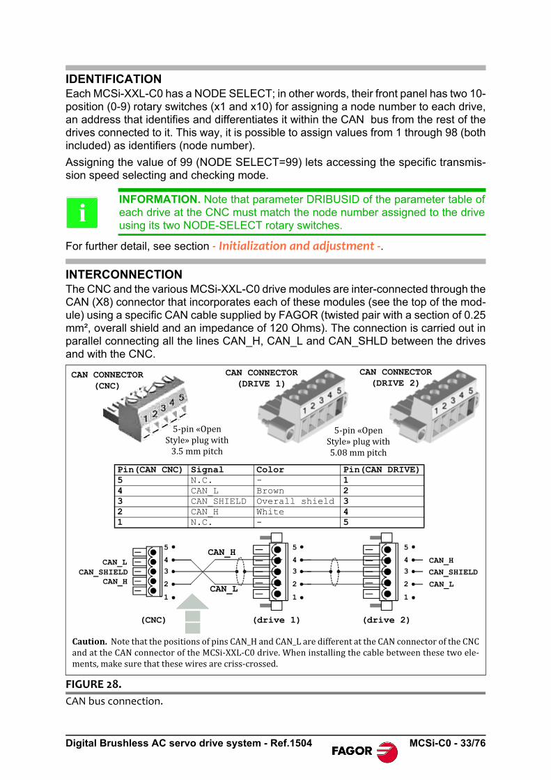
INTERCONNECTIONThe CNC and the various MCSi-XXL-C0 drive modules are inter-connected through theCAN (X8) connector that incorporates each of these modules (see the top of the mod-ule) using a specific CAN cable supplied by FAGOR (twisted pair with a section of 0.25mm², overall shield and an impedance of 120 Ohms). The connection is carried out inparallel connecting all the lines CAN_H, CAN_L and CAN_SHLD between the drivesand with the CNC.
INFORMATION. Note that parameter DRIBUSID of the parameter table ofeach drive at the CNC must match the node number assigned to the driveusing its two NODE-SELECT rotary switches.
FIGURE 28.
CAN bus connection.
i
CAN CONNECTOR(DRIVE 1)
CAN CONNECTOR(DRIVE 2)
5‐pin«OpenStyle»plugwith3.5mmpitch
5‐pin«OpenStyle»plugwith5.08mmpitch
CAN CONNECTOR(CNC)
Caution.NotethatthepositionsofpinsCAN_HandCAN_LaredifferentattheCANconnectoroftheCNCandattheCANconnectoroftheMCSi‐XXL‐C0drive.Wheninstallingthecablebetweenthesetwoele‐ments,makesurethatthesewiresarecriss‐crossed.
5
4
3
2
1
5
4
3
2
1
5
4
3
2
1
CAN_LCAN_SHIELD
CAN_H
CAN_H
CAN_SHIELD
CAN_L
CAN_H
CAN_L
Pin(CAN CNC) Signal Color Pin(CAN DRIVE)5 N.C. - 14 CAN_L Brown 23 CAN_SHIELD Overall shield 32 CAN_H White 41 N.C. - 5
(CNC) (drive 1) (drive 2)
Digital Brushless AC servo drive system - Ref.1504 MCSi-C0 - 33/76

The far end modules connected to the CAN bus (and only these) must have a termi-nating resistor of 120 between CAN_H and CAN_L in order to prevent signal bounc-ing (communication problems). In the case of the CNC, the terminating resistor isfactory installed, assuming that the CNC is always at one of the ends of the bus.
The drive must be installed at the other end of the bus. If it is an MCSi-XXL-C0 drive,the user must install the terminating resistor externally between pins 2 and 4 of con-nector X8.
CAN CABLE LENGTH
The following table shows the maximum length of the network depending on the pos-sible transmission speeds.
CAN CABLE DIAGRAM
INFORMATION. Be especially careful when connecting the CAN cable. Ob-serve that the CAN_H and CAN_L wires are connected to a different pinnumber depending on whether it is the CAN connector of the CNC or that ofthe drive.
TABLE 12. Max. length of a CAN network depending on the transmission speed.
Transmission speed (rate) Length of the CAN network
1000 kbit/s 30 meters
800 kbit/s 50 meters
500 kbit/s 100 meters
250 kbit/s 250 meters
125 kbit/s 500 meters
50 kbit/s 1000 meters
FIGURE 29.
CAN cable diagram.
i
Fagor CAN CABLE 5/10/15/20/25Cable 1x2x0.25Length in meters
Brown
White
2
Signal
34
CAN_LSHIELDCAN_H
Signal
CAN_LSHIELDCAN_H
Pin
234
Pin
Alltheendsofthewiresandtheshieldalreadyhavethepin.Thiscableissuppliedwithoutconnectors.
34/76 - MCSi-C0 Digital Brushless AC servo drive system - Ref.1504

MECHANICAL CHARACTERISTICS OF THE CAN CABLE
SALES MODEL OF THE CAN CABLE
TABLE 13. Mechanical characteristics of the CAN cable.
Type Shield. It ensures EMC compatibility.Outside diameter ext = 6.3 mmFlexibility High. Special to be used in cable carrying chains with a bend-
ing radius of 15ext under dynamic conditions and 8ext under static conditions.
Covering PUR. Polyurethane resistant to chemical agents used in ma-chine-tools.
Temperature Work: - 30 °C to + 70 °C (- 22 °F to 158 °F)Storage: - 5 °C to + 70 °C (33 °F to 158 °F)
Rated voltages Uo / U: 250/1000 V
FIGURE 30.
CAN cable sales model.
CAN CABLE
CAN CABLE
LENGTH (m) 5/10/15/20/25
Example: CAN CABLE 5M
Digital Brushless AC servo drive system - Ref.1504 MCSi-C0 - 35/76

Electrical cabinetHere is an example of a connection diagram for the electrical cabinet that may be mod-ified depending on the needs of each application. It includes a simple circuit for the volt-age supply of the brake of the servo motors.
MAINS CONNECTION AND ELECTRICAL MANEUVER DIAGRAM
The delayed disconnection of KA3 contacts is useful so:
The Drive Enable stays active while the motor brakes at maximum torque.
The brake holds the motor after it has stopped (only on vertical axes).
Also see FIGURE 13. and FIGURE 14.
MANDATORY. The use of fuses is a must.
FIGURE 31.
Diagram of the maneuver.
EMERG.STOP
DR.XOK
FSATHERMALSWITCH
I1 PLC
CNC EMERG.O1 PLC
-KA1
EMERGENCY LINE GND ON OFF TO SPEED ENABLES
-KA4
BRAKECONTROL
-BRK
CNCENABLE
X
KM1
KA3
KM1
+24VDC
X+X-Z+Z-
KA1
ON KM1
OFF
-KM1 DELAYOFF-KA3
DRIVEENABLES
ONGreen
OFFRed
KA3
X3
14
15
13
44
19
43
29
30D3
D4
L2
L1
L2
L1
X5
Power input for the control signalsConnection diagram of the electrical cabinet
DR.X.OK
KA3
KA4
PIN SIGNAL13 DRIVE ENABLE14 COMMON DRIVE SPEED15 SPEED ENABLE19 GND29 DR OK30 DR OK43 24 V DC44 GND AUX 24 V DC
36/76 - MCSi-C0 Digital Brushless AC servo drive system - Ref.1504
Safety DisableThe Safe Disable function (SD) offered by FAGOR MCSi-XXL-C0 drives permits dis-abling the power output of the drive making sure that the motor torque is eliminated asa safe situation.
This function is available through the «Drive Enable» section so called in standardFAGOR servo drive systems. Techniques and elements approved to be used in safetysystems have been considered for its design and internal operation.
Thus, with a conventional drive (without SD), a contactor would have to be installed toassure a safe disable of the motor. However, using the safety techniques (implementedin FAGOR MCSi-XXL-C0 drives) guarantees the same or greater safety without havingto use external contactors, thus saving material and room in the electrical cabinet.
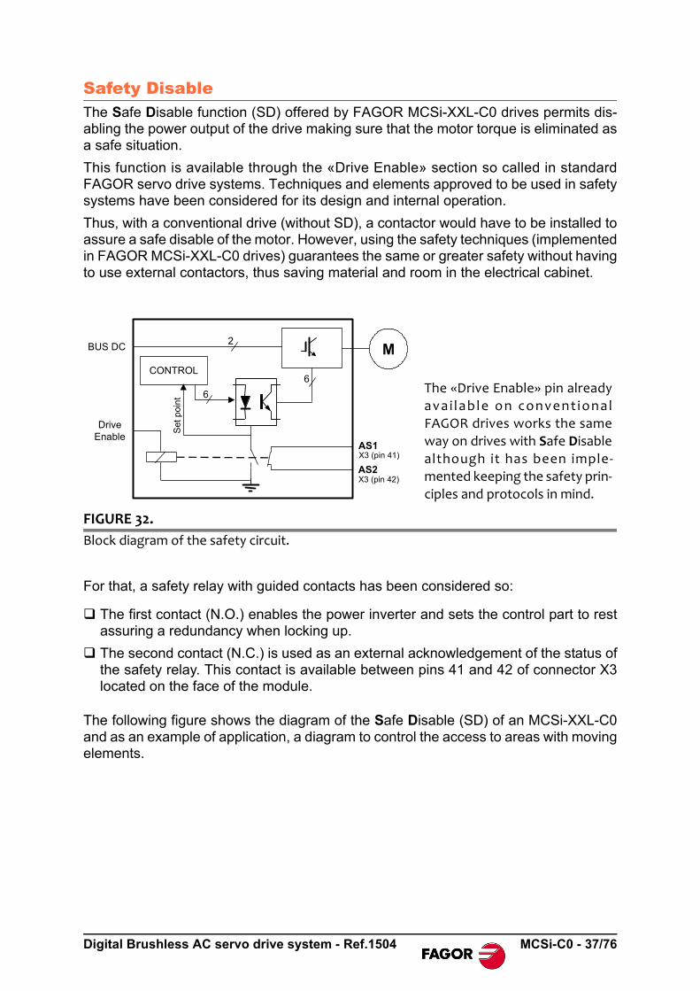
For that, a safety relay with guided contacts has been considered so:
The first contact (N.O.) enables the power inverter and sets the control part to restassuring a redundancy when locking up.
The second contact (N.C.) is used as an external acknowledgement of the status ofthe safety relay. This contact is available between pins 41 and 42 of connector X3located on the face of the module.
The following figure shows the diagram of the Safe Disable (SD) of an MCSi-XXL-C0and as an example of application, a diagram to control the access to areas with movingelements.
FIGURE 32.
Block diagram of the safety circuit.
6
2
6
BUS DC
DriveEnable
CONTROL
Set
poi
nt
M
AS1
AS2
X3 (pin 41)
X3 (pin 42)
The «Drive Enable» pin already
avai lab le on convent ional
FAGOR drives works the same
way on drives with Safe Disable
although it has been imple‐
mented keeping the safety prin‐
ciples and protocols in mind.
Digital Brushless AC servo drive system - Ref.1504 MCSi-C0 - 37/76

The diagram to control the access to areas with moving elements is:
FIGURE 33.
Safety relay and access control diagram with moving elements.
FIGURE 34.
Diagram to control the access with moving elements.
{
M
Mains
CONTROL
MC
Si-
XX
L-C
0
L2 L1
RST
Inductance
Control of access to areas with moving elementsSafety relay
Drive EnableX3 (pines 41 y 42)Safety Relay
X3 (pin 13)
WORK ZONE 1
S1
Mai
ns
L1
T
Inductance
S2
L2
MC
Si-
XX
L-C
0
MC
Si-
XX
L-C
0
MC
Si-
XX
L-C
0
MC
Si-
XX
L-C
0
MC
Si-
XX
L-C
0Nº1
Dri
ve
Ena
ble
X3
(41
)X
3 (4
2)
Dri
ve
Ena
ble
X3
(41
)X
3 (4
2)
Dri
ve
Ena
ble
X3
(41
)X
3 (4
2)
Dri
ve
Ena
ble
X3
(41
)X
3 (4
2)
Dri
ve
Ena
ble
X3
(41
)X
3 (4
2)
S
RNº2 Nº3 Nº4 Nº5
WORK ZONE 2
S1
K1
+24 V DC
Emergency button
S2
Locking up drives 1 & 2
Locking un drives 3, 4 & 5
Driv
e E
nabl
e 1
Driv
e E
nabl
e 2
Driv
e E
nabl
e 3
Driv
e E
nabl
e 4
Driv
e E
nabl
e 5
X3 (41 & 42)
Cycle stop
Cycle start
System OK.
K1
X3 (41 & 42)
X3 (41 & 42)
X3 (41 & 42)
X3 (41 & 42) MCSi-C0 Nr 1
MCSi-C0 Nr 2
MCSi-C0 Nr 3
MCSi-C0 Nr 4
MCSi-C0 Nr 5
38/76 - MCSi-C0 Digital Brushless AC servo drive system - Ref.1504

Initialization and adjustmentThe initialization and setup process on MCSi-XXL-C0 units may be done through theinterface provided by the CNC or also through the FAGOR's PC software (WinDDS-Setup).
On startup, the drive will look, in the memory of the digital feedback device integratedinto the motor, for the information on the type of motor connected. If the motor recog-nized by the drive is different from the one it was governing up to that moment, it willautomatically adjust the critical parameters related to the motor type.
However, it is recommended to initialize it using the GC10 command the first time a unitis started up or every time a motor is changed in order to set the initial values (bydefault) of all the parameters of the drive verifying them with the selected motor.
The GC1 command must be executed in order for these default values to stay saved inthe static memory of the unit (flash, E²PROM, etc.).
Likewise, the GC1 command must also be executed to change a particular parameterafter loading the default parameters, and have the new value saved permanently
MCSi-XXL-C0 units have four 7-segment displays on its face plate for showing the dif-ferent states of the drive and, in case of error, the error code active at the module Tointerpret the error code, refer to the section - ERROR CODES -.
FIGURE 35.
Codes that may be shown at the displays of the module.
After powering the unit or after a RESET, it briefly shows thesoftware version. This display shows v.1.0.1 indicating version1.01.
Low Bus. The unit has control voltage, but the power input (X4)has no voltage or the internal power bus has not been stabilizedyet.
The unit has stabilized power voltage (therefore control voltageas well) and DRIVE ENABLE and SPEED ENABLE are deacti-vated.
The unit has stabilized power voltage, DRIVE ENABLE is acti-vated and SPEED ENABLE is deactivated.
Ready1. The unit is regulating with PWM pulses and with DRIVEENABLE and SPEED ENABLE activated
Ready0. If SPEED ENABLE is deactivated in Ready 1 state, theunit carries out an emergency stop (Rdy. 0) until it stops and goesinto the state (Rdy. -) without pulses.
If an error comes up in the unit at any time, the displays blinkshowing the active error. On this display, error 003.
Digital Brushless AC servo drive system - Ref.1504 MCSi-C0 - 39/76

Standard CAN parameter settingMCSi-XXL-C0 have three transmission PDO channels and three reception channelsfor transferring certain predetermined variables at high speed. These are called fastchannels and make it possible to control modules in real time.
The messages transmitted through these channels carry words for status, control,velocity command and feedback.
The actions to «save» and «load» parameters by the drive are handled through thestandard objects 1010h (save parameters) and 1011h (restore default parameters). Inorder for the action to have an effect, the «save» and «load» values must be writtenrespectively in those parameters. For the object 1011h, the default parameters will berestored after the next RESET of the unit.
Both actions may be carried out by groups of parameters depending on the subindexbeing accessed. See the following tables.
This way, when writing the hexadecimal value 64616f6Ch in object 1011.4, it loads thedefault OEM parameters, i.e. all the ones appearing in section - PARAMETERS, VARI‐ABLES & COMMANDS - of this manual.
INFORMATION. We recommend to set QP17=32 when the master device isnot a FAGOR CNC. See QP17 in section - PARAMETERS, VARIABLES &COMMANDS - of this manual.
Observe that on drives to be governed by a master device other than a FAGOR CNC,these PDO messages (messages used by CAN through the fast channel) may haveto be modified in order to adapt them to the master device.
TABLE 14. Indexes.
Index Description Hex. value ASCII
1010 Save parameters into FLASH 65766173h “save”
1011 Restore default (factory set) 64616f6Ch “load”
TABLE 15. Sub‐indexes.
Sub-index Description
1 All parameters
2 Communication parameters (indexes 1000h through 1FFFh)
3 Not supported. Application parameters (6000h through 9FFFh)
4 OEM parameters (2000h through 5FFFh)
INFORMATION. Observe that commands GC1 and GC10 carry out the ac-tions to «save» and «load» all parameters of the drive and are the same asexecuting the subindex 1 of objects 1010h and 1011h, with the only differ-ence that the actions of these commands are immediate (they do not needa RESET like the object 1011h).
i
i
40/76 - MCSi-C0 Digital Brushless AC servo drive system - Ref.1504

The following table shows the mapping of sending and receiving PDO 1 that are loadedby default (object 1011.2h, load communication parameters) for node 1. PDO 2 andPDO 3 have a null mapping.
The following table shows the default communication parameters of sending andreceving PDO 1.
Default PDO mapping
TABLE 16. Mapping of sending and receiving PDO 1.
Object 1A00h - sending PDO 1 mapping
Sub-index Value Meaning
0 2 Two objects are mapped in this PDO
1 50870010h Index: 5087h Subindex: 00hData: 16 bits (DriverStatusWord)
2 50330020h Index: 5033h Subindex: 00hData: 32 bits (PositionFeedback)
Object 1600h - receiving PDO 1 mapping
Sub-index Value Meaning
0 2 Two objects are mapped in this PDO
1 50860010h Index: 5086h Subindex: 00hData: 16 bits (MasterControlWord)
2 50240020h Index: 5024h Subindex: 00hData: 32 bits (VelocityCommand)
Default PDO communication
TABLE 17. PDO 1 communication types, send and receive.
Object 1800h - Type of sending PDO 1 communication
Subindex Value Meaning
0 5 Five objects are mapped in this PDO
1 00000181h Bit 31 0 - PDO enabled
1 - PDO disabled
Bits 10-0 Message ID
2 1 Type of transmission (read the describing section)
3 0 Inhibit time (*100 µs) - see example 1 -
4 - Reserved
5 0 Event timer (*1ms) - see example 1 -
Object 1400h - Type of receiving PDO 1 communication
Subindex Value Meaning
0 2 Two objects are mapped in this PDO
1 00000201h Bit 31 0 - PDO enabled1 - PDO disabled
Bits 10-0 Message ID
2 1 Type of transmission (read the describing section)
Digital Brushless AC servo drive system - Ref.1504 MCSi-C0 - 41/76

<SYNC> means that the transmission of the PDO has to do with the reception of thesynchronism message.
<ASYNC> means that the transmission of the PDO has nothing to do with the receptionof the synchronism message.
Type of transmission = 0. Synchronous and non-cyclic. The messages are only sentwhen an event takes place and, in that case, the message is sent in synchronism withthe next synchronism message.
Type of transmission = 1 to 240. The PDO is transmitted after receiving the numberof synchronism messages specified in the type of transmission.
Type of transmission = 252 to 253. Values only possible in transmission PDO's. Ineither case, the PDO is sent as response to an RTR frame of the master device. Thedifference is that in the type of transmission equal to 252 it updates the variables whenreceiving the synchronism and the transmission equal to 253 updates the variables andsends them when receiving the RTR frame.
Type of transmission = 254. The PDO is transmitted when some OEM-specific eventoccurs.
Type of transmission = 255. The PDO is transmitted when some device-profile-spe-cific event occurs.
Type of transmission (value of sub-index 2)
TABLE 18. Type of transmission (value of sub‐index 2).
Type of transmission
PDO trigger condition(B = both required; O = one or both required)
PDOtransmission
SYNCSYNC object received
RTRReceived request for remote transmission
EventValue change of the interruption of the timer
0 B B Synchronous (SYNC), non-cyclic
1-240 O Synchronous (SYNC), cyclic
241-251 Reserved252 B B Synchronous (SYNC),
after RTR253 O Asynchronous (ASYNC),
after RTR254(*) O O Asynchronous (ASYNC),
OEM-specific event255(*) O O Asynchronous
(ASYNC),device-profile-specific event
(*) in either case, a message will be sent when the value of any variableto be sent changes or when an event of the timer takes place (object1800.5h).
An event is a change of value of the variable or (if it is supported by the equipment,communication objects with subindex 5) to a particular amount of time elapsed.
42/76 - MCSi-C0 Digital Brushless AC servo drive system - Ref.1504

Example 1. Explanation for the inhibit time and the event timer.
When programming a type-254 transmission PDO that includes a position variable, twodifferent scenarios occur. As long as the device sending the PDO is stopped (its posi-tion has not changed), it will not be necessary to send anything. However, when pro-gramming an event timer with a value of 10 (10 x 1 ms), even if the element does notmove (it does not change its position variable), it will send PDO's every 10 ms indicat-ing its position. Then, when starting to move, it will try sending PDO's constantly, thustaking up the whole bus with this information. In order to prevent this situation, an inhibittime of 20 (20 x 100 µs = 20 ms) may be programmed so it only sends PDO's every 2ms while it is moving.
Speed selection and node number
MS Led Module Status Led. Two-color light emitting diode (red and green) toindicate the status of the drive.
NS Led Network Status Led. Two-color light emitting diode (red and green) toindicate the status of the unit within the communications CAN bus.
"x1" and "x10" switches Rotary switches for selecting a digit between 0 and 9on each one and whose combination gives a number between 0 (when both are setto 0) and 99 (when both are set to 9). Each node of the bus differs from the rest inthe node number assigned to it using these rotary switches. A unit may assumeany node number between 01 and 98.
FIGURE 36.
Drive elements involved in CAN communication.
RE
SE
T
NO
DE x1
0x1
NS
Digital Brushless AC servo drive system - Ref.1504 MCSi-C0 - 43/76

When incorporating a new unit in a CANopen network, the first thing to do is to adaptthe communication speed to the speed of the network. There are two rotary selectorswitches (x10, x1) and two indicators MS (Module Status) and NS (Network Status) tomake the selection.
The transmission speeds (baudrate) that may be selected in CANopen are 10, 20, 50,100, 125, 250, 500, 800 and 1000 (in kbits/s).
Selecting procedure
The transmission speed selection mode is enabled when powering the unit up aslong as the rotary selector switches are selecting the number 99 (that is when bothswitches are set to 9). The MS and NS LED's blink a green light at the same time witha period of about 500 ms indicating that the communication baudrate selection mode isenabled. The following operations are possible in this state:
Verify the selected transmission speed
To know the communication speed on the network at that very instant, turn therotary selector "x1" to the "0" position. The MS indicator blinks a red light a numberof times and it then turns off for about 1 second. After that time, it starts this samesequence again.
The number of red blinks between two intervals where the LED is off indicates thecommunication baudrate (saved in memory) used to connect the unit to the net-work.
The table shows the relationship between the number of red blinks of the MS LEDand the network's baudrate:
INFORMATION. Note that parameter DRIBUSID of the parameter table ofeach drive at the CNC must match the node number assigned to the driveusing its two NODE SELECT rotary switches.
Note. 0 and 99 can only be used in special cases that are described later on.
Communication speed selection
TABLE 19. Baudrate verification.
Nr of blinks of the MS LED
Transmission speed (rate)
Nr of blinks of the MS LED
Transmission speed (rate)
1 1000 kbit/s 6 100 kbit/s
2 800 kbit/s 7 50 kbit/s
3 500 kbit/s 8 20 kbit/s
4 250 kbit/s 9 10 kbit/s
5 125 kbit/s
i
44/76 - MCSi-C0 Digital Brushless AC servo drive system - Ref.1504

Example
If the red MS LED blinks 3 times (between the periods when it's off), it will indicate,according to this table, that the transmission speed (baudrate) is 500 kbits/s.
Selecting the transmission speed
To set the same baudrate at the new unit as that of the communication on the network,turn its rotary selector "x1" to a position between 1 and 9 to select one of the baudrates.
Example
If the network communication baudrate is 500 kBd, the unit being connected must alsotransmit at that speed; i. e. its rotary switch "x1" must be set to position 3.
At the same time and with the same sequences mentioned earlier, the green light of theMS LED will blink identifying the selected baudrate.
Once the position has been selected at the "x1" switch, it is necessary to confirm theselection. To do this, rotate the "x10" switch to position 0. The red blinking light of theMS LED will indicate the selected baudrate. After this operation, this baudrate will besaved permanently in the non-volatile memory of the unit. After resetting the unit, it willassume the baudrate saved in memory as the transmission speed.
Once the transmission speed of the unit in the network has been set, it must then beidentified within the network. A unique identifier must be assigned to the new unit todifferentiate it from any other unit of the network, thus avoiding collisions. This identify-ing number ID will be referred to as node number and must be different for eachunit.
The unit's node number is set using the two rotary switches x1 and x10.
TABLE 20. Baudrate selection.
Position of the rotary switch "x1"
Transmission speed (rate)
Position of the rotary switch "x1"
Transmission speed (rate)
1 1000 kbit/s 6 100 kbit/s
2 800 kbit/s 7 50 kbit/s
3 500 kbit/s 8 20 kbit/s
4 250 kbit/s 9 10 kbit/s
5 125 kbit/s
Setting the node number
IMPORTANT. It is up to the user to prevent two units from having the same nodenumber.
Digital Brushless AC servo drive system - Ref.1504 MCSi-C0 - 45/76

Example
After resetting the drive, it will be identified in the network with the node numberassigned to it.
On each start-up, the unit assumes as node number the one assigned at rotaryswitches "x1" and "x10".
The CAN card of the drive only has two two-color indicator LED's. They are, MS (Mod-ule Status) and NS (Network Status). The MS indicator shows the unit status and theNS the status of the unit within the CANopen® network.
In an initial process of the unit, these LED's reach the following states in order to verifythe proper state of the drive.
The node number selection range on a CANopen network is between 01 and 127.Remember that node number 99 is reserved for the baudrate selection process and00 is treated as 01 since there is no node 00 in CANopen®.
Status indicators
FIGURE 37.
Status indicators.
Note. MS and NS turn on according to the status of the bus and of the unit.
To assign node number 57 to a unit, turn the rotary switch "x10" toposition 5 and rotary switch "x1" to position 7. See attached figure.
Verify that 10 x 5 + 1 x 7 = 57.
NS(green)
on
off
NS(red)
on
off
MS(green)
on
off
on
off
MS(red)
250 ms
250 ms
250 ms
250 ms
46/76 - MCSi-C0 Digital Brushless AC servo drive system - Ref.1504

This indicator informs about the unit status as such. The states that may be reached, atthis time, are:
Running. The drive is error free. The indicator LED will blink green with a 200 ms on/off period.
In error. The drive is in an error state. The indicator LED will blink red and faster thanin the previous state with a 50 ms on/off period.
This indicator informs of the unit status within the CANopen® network; i.e. of the CANo-pen® Bus status. See the following tables and figures that set the intermittent frequen-cies of the red and green LED's and their names.
Red LED. Error indicator LED.
See FIGURE 38.
Green LED. Status indicator LED
See FIGURE 38.
MS (Module Status)
NS (Network Status)
TABLE 21. Error indicator LED. Red color.
Error LED (red) Status Description
OFF No errors Unit running properly.
A single blink Warning limit reached
At least one of the error counters of the CANdriver has reached or exceeded the warninglevel. Too many error frames.
Double blinking NMT error control event
Either a «guarding» event (slave NMT ormaster NMT) or a «heartbeat» event (heart-beat consumer) has occurred.
Triple blinking Bus off The CAN control is in "bus off" mode.
TABLE 22. Status indicator LED. Green color.
Running LED (green) Status Description
ON Operational The drive is in an operational state.
blinking Pre-operational The drive is in a pre-operational state.
A single blink Stopped The unit is in a stop state.
Digital Brushless AC servo drive system - Ref.1504 MCSi-C0 - 47/76

WinDDSSetupIt is a FAGOR application for PC. The operator can use the application's interface toread, modify, save to a PC file and download from a PC file all the parameters and vari-ables of the drive and check the status of the motor-drive combination; thus making thefinal adjustment of the servo drive system easier, faster and more comfortable. Thisalso makes it easier to manufacture many machines that have MCS Innova units.
When installing the WinDDSSetup, the USB drivers are also installed. These driversgenerate an additional virtual COM port to those already used by the PC and it will onlybe present when the unit is connected and is applied control or power voltage.
This is why, the unit should be connected first and then run WinDDSSetup.
FIGURE 38.
Names and blinking times of the NS (Network Status) indicator LED.
triple flash(green)
on
off
triple flash(red)
on
off
doble flash(red)
on
off
single flash(green)
on
off
single flash(red)
on
off
blincking(green)
on
off
blincking(red)
on
off
flickering(green)
on
off
flickering(red)
on
off
50 ms
200 ms6 x 200 ms 1000 ms
48/76 - MCSi-C0 Digital Brushless AC servo drive system - Ref.1504

The first time the unit is connected to the PC, the operating system will show two mes-sages indicating that «new hardware has been detected».
When starting the WinDDSSetup application, you must select the virtual COM port inorder establish communication with the unit.
To obtain information on the generated COM port, proceed as follows:
Click the right button of the mouse on the icon «My PC».
Select the «Properties» option and the «Hardware» label in the next popup window
Select «Device administrator»
The window will show them as:
Multiple serial port adapters, the reference MOTION CONTROL INNOVA.
Ports (COM & LPT), reference USB-Serial Port (COMx). The digit appearing in thex position refers to the new virtual COM port for the PC.
Do the «default» installation, recommended by the system and ignore the messageregarding the incompatibility tests of the software with the operating system Win-dows® XP that comes up during the installation process. Go on by pressing the «con-tinue» button. This message refers to the drives that have not been certified yet.However, they are fully functional.
Digital Brushless AC servo drive system - Ref.1504 MCSi-C0 - 49/76

PARAMETERS, VARIABLES & COMMANDSThe parameters, variables and commands of the drive that are shown next may beused with any device that works as master. Besides all these, there are others that maybe used to communicate the drive with the CNC.
Unit interpretationThe number of decimals in the units of all parameters and variables of the drive repre-sented on the CNC screen and on the WinDDSSetup will match strictly the onesdescribed in this manual. However, the same ones requested via CAN or serial line bystandard communication programs will be returned with their maximum resolutionbeing up to the user to interpret them correctly.
Example
If the CNC shows the CV3 variable with a value of 1.26 A, this same variable requestedvia CAN will have a value of 126 and its units will, therefore, be hundredths of an Amp(x10-2 A).
Observe that the number of decimals refers to the number of digits after the decimalpoint (or comma) in the «valid values» field of any parameter, variable or command ofthe drive documented in this manual.
Notation used and definition of groups
where:
GROUP. Identifying character of the logic group to which the parameter or variablebelongs. There are the following groups of parameters:
GROUP TYP INDEX NO MOD. EVEN ACCESS VAR.MOD CAN ID NAME
TABLE 23. Groups of parameters, variables and commands.
Nr Function Group Letter1 Control signals Terminal box B2 Current control loop Current C3 Error diagnosis Diagnosis D4 General of the system General G5 System hardware Hardware H6 Analog and digital inputs Inputs I7 Temperatures and voltages Monitoring K8 Motor properties Motor M9 Mechanical elements Mechanical N10 Analog and digital outputs Outputs O11 Position control loop Position P12 System communication Communication Q13 Rotor sensor properties Rotor sensor R14 Velocity control loop Speed S15 Torque and power parameters Even T
50/76 - MCSi-C0 Digital Brushless AC servo drive system - Ref.1504
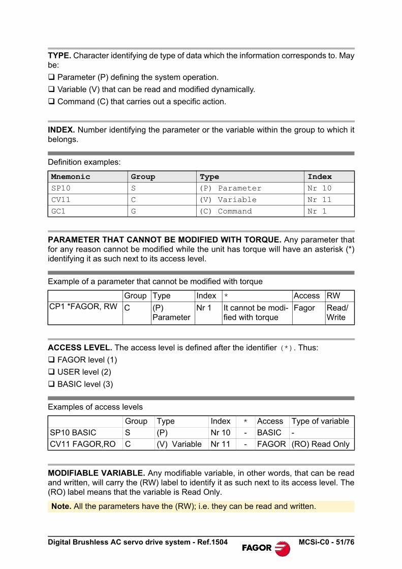
TYPE. Character identifying de type of data which the information corresponds to. Maybe:
Parameter (P) defining the system operation.
Variable (V) that can be read and modified dynamically.
Command (C) that carries out a specific action.
INDEX. Number identifying the parameter or the variable within the group to which itbelongs.
Definition examples:
PARAMETER THAT CANNOT BE MODIFIED WITH TORQUE. Any parameter thatfor any reason cannot be modified while the unit has torque will have an asterisk (*)identifying it as such next to its access level.
Example of a parameter that cannot be modified with torque
ACCESS LEVEL. The access level is defined after the identifier (*). Thus:
FAGOR level (1)
USER level (2)
BASIC level (3)
Examples of access levels
MODIFIABLE VARIABLE. Any modifiable variable, in other words, that can be readand written, will carry the (RW) label to identify it as such next to its access level. The(RO) label means that the variable is Read Only.
Mnemonic Group Type IndexSP10 S (P) Parameter Nr 10
CV11 C (V) Variable Nr 11GC1 G (C) Command Nr 1
Group Type Index * Access RWCP1 *FAGOR, RW C (P)
ParameterNr 1 It cannot be modi-
fied with torqueFagor Read/
Write
Group Type Index * Access Type of variable
SP10 BASIC S (P) Nr 10 - BASIC -
CV11 FAGOR,RO C (V) Variable Nr 11 - FAGOR (RO) Read Only
Note. All the parameters have the (RW); i.e. they can be read and written.
Digital Brushless AC servo drive system - Ref.1504 MCSi-C0 - 51/76

Example of a modifiable variable
ID CAN. CAN identifier of the parameter, variable or command.
NAME. Name of the parameters, variable or command.
Handling internal variables
Fast communication channel. The data exchange between the CNC and the drivestakes place and is refreshed at every position loop. This data has the commands, thefeedback, etc. Each variable written or read at the drive is included in this informationpackage. Every loop time, the CNC transmits to the drive through this channel somefixed variables and others that may be accessed. The variables that may be accessedthrough the fast channel may be either read (R) or write (W) variables).
All the drive variables set as accessible from the CNC are:
Group Type Index Access Type of variable
DV32 FAGOR, RW D (V) Variable Nr 32 FAGOR (RW) Read-Write
INFORMATION. Accessing a drive variable from the CNC set as accessiblethrough the fast channel requires its SERCOS identifier (ID. SERCOS), nev-er the ID CAN even if the communication interface is CAN.
Variable Name R/W ID SERCOSBV14 NotProgrammableIOs R 32972CV1 Current1Feedback R 33077CV2 Current2Feedback R 33078CV3 CurrentFeedback R 33079DV31 DriverStatusWord R 00135DV32 MasterControlWord W 00134IV10 DigitalInputs R 33675KV10 CoolingTemperature R 33870KV32 I2tDrive R 33877KV36 I2tMotor R 33879KV40 I2tCrowbar R 33883OV10 DigitalOutputs W 34178PV51 PositionFeedback1 R 00051QV30 FiberDistErrCounter R 33495QV190 CanBusSyncJitter R 34779SV1 VelocityCommand W 00036SV2 VelocityFeedback R 00040SV6 VelocityCommandAfterFilters R 34390SV7 VelocityCommandFinal R 34380TV2 TorqueFeedback R 00084
i
52/76 - MCSi-C0 Digital Brushless AC servo drive system - Ref.1504

B group. Non-programmable inputs-outputs
Function. Indicates the logic values of the electrical signals of the drive'scontrol. 24 V at the electrical input mean a logic 1 at the bits of thisvariable.
C group. Current
Function. Value of the proportional action of the current PI
Valid values. 0,..., 999.
Default value. Depends on the motor-drive combination.
Function. Value of the integral action of the current PI.
Valid values. 0,..., 999.
Default value. Depends on the motor-drive combination.
Function. limit of the current command that reaches the system's currentloop.
Valid values. 0.00, ..., 50.00 Arms. CP20 must never exceed the smallest valuegiven by the peak current of the motor (5 x MP3) and of the drive.
Default value. CP20 takes the lowest value of the ones given by the motor anddrive peak currents.
Function. Parameter in charge of enabling / disabling the current filter.
Valid values. 1/0 Enables/Disables the current filter.
Default value. 0 Current filter disabled.
BV14 FAGOR, RO 0x40CC NotProgrammableIOs
Bit Function
15, ..., 4 Reserved
3Programmable inputPins 11 and 12 of terminal strip X3
2"Drive OK" outputPins 29 and 30 of terminal strip X3
1Speed Enable inputPin 15 of terminal strip X3
0Drive Enable inputPin 13 of terminal strip X3
Read variable from the CNC through the fast channel. ID.SERCOS: 32972
CP1 *FAGOR, RW 0x506A CurrentProportionalGain
CP2 *FAGOR, RW 0x506B CurrentIntegralTime
CP20 USER, RW 0x4133 CurrentLimit
CP30 FAGOR, RW 0x4134 CurrentCommandFilter1Type
Digital Brushless AC servo drive system - Ref.1504 MCSi-C0 - 53/76

Function. Sets the natural frequency in Hz of a notch filter that acts upon thecurrent command.
Valid values. 0, ..., 4000 Hz.
Default value. 0.
Function. Sets the bandwidth in Hz of a notch filter that acts upon the currentcommand.
Valid values: 0, ..., 1000 Hz.
Default value: 0.
Function. Display the value of the feedback of the current going throughphase V.
Valid values. - 50.00, ..., 50.00 A (instant values).
Function. Display the value of the feedback of the current going throughphase W.
Valid values. - 50.00, ..., 50.00 A (instant values).
CP31 FAGOR, RW 0x4138 CurrentCommandFilter1Frequency
CP32 FAGOR, RW 0x4139 CurrentCommandFilter1Damping
CV1 BASIC, RO 0x4135 Current1Feedback
Read variable from the CNC through the fast channel. ID.SERCOS: 33077
CV2 BASIC, RO 0x4136 Current2Feedback
Read variable from the CNC through the fast channel. ID.SERCOS: 33078
54/76 - MCSi-C0 Digital Brushless AC servo drive system - Ref.1504

Function. Display the rms current circulating through the motor.
Valid values. -50.00, ..., 50.00 A (rms values).
Function. Value of the automatic compensation of the current feedback offsetof phase V.
Valid values. -2.000, ..., 2.000 A (depends on the connected drive).
Function. Value of the automatic compensation of the current feedback offsetof phase W.
Valid values. -2.000, ..., 2.000 A (depends on the connected drive).
D group. Diagnosis
Function. Stores the last 5 errors that came up at the drive. It consists in a5-word register that stores the code of each one of them.
Valid values. All the codes of the list of possible errors of the software versioncurrently loaded. Code 0 means no error.
Function. Variable that contains a numerical data coded into 16 binary bitsand represents the system status in certain aspects as shown bythe attached table. This variable communicates with the CNCthrough the CAN interface.
CV3 BASIC, RO 0x4137 CurrentFeedback
Read variable from the CNC through the fast channel. ID.SERCOS: 33079
CV10 FAGOR, RO 0x4131 Current1Offset
CV11 FAGOR, RO 0x4132 Current2Offset
DV17 BASIC, RO 0x419A HistoricOfErrors
DV31 FAGOR, RO 0x5087 DriverStatusWord
CURRENTREADING
CV1
AD
_sin
CV2
CV10
CV11IW
IV
_cos
Digital Brushless AC servo drive system - Ref.1504 MCSi-C0 - 55/76

Function. Variable that contains a numerical data that in 16-bit binary coderepresents the control signals that the CNC sends to the drivethrough the CAN interface. See attached table. This variablecommunicates with the CNC through the CAN interface.
Function. Reset of the unit's errors. When an error occurs, this commandmay be used to reset it and restart the unit by first updating theerror bit of DV31, DriveStatusWord, and then setting the drive inthe ReadyForPower state. Note its difference with the unit's resetbecause the action carried out by this command keeps the RAMmemory intact and therefore the parameter settings of the unit.
Function. Reset of the «DV17 (F00410) HistoricOfErrors (array)» variable.This command sets it to 0.
Bits Meaning
15, 14 Power & Torque Status(0,0) DoingInternalTest [DRVSTS_INITIALIZATING](0,1) ReadyForPower [DRVSTS_LBUS](1,0) PowerOn [DRSTS_POWER_ON](1,1) TorqueOn [DRSTS_TORQUE_ON]
13 Error bit.
12 Warning bit
11 0
10, 9, 8 = 0, PrimaryOperationMode
7 Real time status bit
6 Real time status bit
5, 4, 3, 2, 1, 0 Reserved
Read variable from the CNC through the fast channel. ID.SERCOS: 00135
DV32 FAGOR, RW 0x5086 MasterControlWord
Bits Name
15 Speed Enable (SPENA)
14 Drive Enable (DRENA)
13 Halt
12, 11, 10 Reserved
9, 8, 7, 6, 5 Reserved
4, 3, 2, 1, 0 Reserved
Write variable from the CNC through the fast channel. ID.SERCOS: 00134
DC1 BASIC, RW 0x5063 ResetClassDiagnostics
DC2 BASIC, RW 0x4192 ClearHistoricOfErrorsCommand
56/76 - MCSi-C0 Digital Brushless AC servo drive system - Ref.1504

G group. General
Function. After deactivating the Speed Enable and after the GP3 time haselapsed, if the motor has not stopped, it cancels the torque auto-matically and issues error E.004. If the motor stops within theGP3 time, it also cancels the torque but does not issue an error.To make this time infinite (never generating error E.004), set thisparameter to "0".
Valid values: 1 ... 9999 ms, 0 (infinite).
Default value: 500 ms.
Function. This parameter represents the version of the parameter table thathas been loaded at the drive.
Function. After the motor has stopped because the Speed Enable functionhas been disabled, the cancellation of the the Drive Enable func-tion (that implies PWM-OFF) is delayed by a time period indi-cated by GP9. It is useful on axes not compensated with aholding brake. To make this time period infinite, set it to 0 and toremove it, set it to 1.
Valid values. 1 ... 9999 ms, 0 (infinite).
Default value. 50 ms.
Function. Displays the software version in use.
Function. It registers the checksum value of the software version loaded atthe drive.
Function. Variable where the password is entered to change the accesslevel. The system will change the access level corresponding tothe password entered.
Valid values. 0,..., 9999.
Default value. 0.
Function. This variable informs of the drive's sales reference.
Function. Variable that resets the unit by software.
Valid values. 0,..., 16.
Default value. 0.
GP3 USER, RW 0x42BE StoppingTimeout
GP5 USER, RO 0x42C0 ParameterVersion
GP9 USER, RW 0x50CF DriveOffDelayTime
GV2 USER, RO 0x501E ManufacturerVersion
GV5 USER, RO 0x42C2 CodeChecksum
GV7 USER, RW 0x510B Password
GV9 USER, RO 0x508C DriveType
GV11 USER, RW 0x42C4 SoftReset
Digital Brushless AC servo drive system - Ref.1504 MCSi-C0 - 57/76

Function. Version of the motor table.
Function. List of the error numbers active in the unit.
Function. Command to execute the parameter transfer from RAM toE²PROM.
Valid values. 0,..., 15.
Default value. 0.
Function. Command to initialize parameters. This command loads thedefault drive parameters for a motor that has been previouslyselected with parameter MP1.
Valid values. 0,..., 15.
Default value. 0.
H group. Hardware
Function. Software version installed in the unit's PLD's.
I group. Inputs
Function. Sets the polarity (inverted or not inverted) of the programmabledigitalinput (pins 11 and 12 of X3).
Valid values. 0/1 Not inverted/inverted.
Default value. 0 Not inverted.
Function. This variable reflects the status of the programmable digital inputat pins 11 and 12 of connector X3. Its state is affected by IP6.
Valid values: 0 and 1.
GV16 USER, RO 0x42CC MotorTableVersion
GV75 FAGOR, RO 0x5177 ErrorList
GC1 USER, RW 0x5108 BackupWorkingMemoryCommand
GC10 *USER, RW 0x5106 LoadDefaultsCommand
HV5 USER, RO 0x4127 PLDVersion
IP6 BASIC, RW 0x438E DigitalInputPolarity
IV10 BASIC, RO 0x438B DigitalInputs
Read variable from the CNC through the fast channel. ID.SERCOS: 33675
X3.11
IV10
0
IP61
PR
OG
_DIG
_IN
PU
T
X3.12
58/76 - MCSi-C0 Digital Brushless AC servo drive system - Ref.1504

K group. Monitoring
Function. Contains the value of power of the external ballast resistor.
Valid values: 200,..., 2000 W.
Default value: 200 W.
Function. Contains the value of the energy pulse that can be dissipated bythe external ballast resistor.
Valid values. 200, ..., 2000 J.
Default value. 200 J.
Function. It displays the temperature of the heatsink of the power stage.
Valid values. 0, ..., 200 °C.
Function. Variable internally useful to the system. It measures the internalload level of the calculation of the i²t at the drive in percentageused over the maximum.
Valid values. 0, ..., 100 %.
Function. Variable internally useful to the system. It measures the internalload level of the calculation of the i²t at the motor in percentageused over the maximum.
Valid values. 0, ..., 100 %.
Function. Shows the load percentage on the ballast resistor in a drive. Use-ful for the i²t protection of the resistor. A value greater than 100%in this variable causes error E314.
Valid values. 0, ..., 100 %.
Function. Selector that determines whether the ballast resistor is external orinternal.
Valid values: 0/1 External/internal (by default).
KP3 BASIC, RW 0x445A ExtBallastPower
KP4 BASIC, RW 0x445C ExtBallastEnergyPulse
KV10 BASIC, RO 0x444E CoolingTemperature
Read variable from the CNC through the fast channel. ID.SERCOS: 33870
KV32 BASIC, RO 0x4455 I2tDrive
Read variable from the CNC through the fast channel. ID.SERCOS: 33877
KV36 BASIC, RO 0x4457 I2tMotor
Read variable from the CNC through the fast channel. ID.SERCOS: 33879
KV40 BASIC, RO 0x445B I2tCrowbar
Read variable from the CNC through the fast channel. ID.SERCOS: 33883
KV41 BASIC, RW 0x445D BallastSelect
Digital Brushless AC servo drive system - Ref.1504 MCSi-C0 - 59/76

M group. Motor
Function. Motor identification. The limits of certain parameters depend onthe value of MP1 (e.g.: The upper limit of SP10 is 110% of themotor rated speed) like its default parameter initialization throughGC10. See GC10.
Function. Contains the torque constant of the synchronous motor, (motortorque according to the rms current)
Valid values. 0.00, ..., 10.00 Nm/Arms.
Function. Contains the motor rated current. Manipulating MP3 may affectparameter CP20 directly. See CP20.
Valid values. 0.00, ..., 50.00 Arms. Depends on the motor connected.
Function. Contains the motor peak current. This current value must NEVERbe exceeded in the motor. See CP20.
Valid values. 0.00, ..., 50.00 Arms. Depends on the motor connected.
Default value. It depends on the motor connected.
N group. Mechanical
Function. Parameter that cannot be modified by the user that «tells» the CNCthe number of pulses of the motor feedback.
Valid values. 0, ..., 65535 pulses.
Function. They define the gear ratio between the motor shaft and the finalaxis moved by the machine. For example, if 5 turns of the motorshaft mean 3 turns of the machine leadscrew, the value of theseparameters is NP121=5 and NP122=3.
Valid values. 1, ..., 32767 turns
Default value. 1 turn in both parameters (direct coupling).
Function. It defines the gear ratio between the linear movement of themachine and the axis moving it. For example, if every turn of theleadscrew means a 4 mm displacement of the table, the value forthis parameter is NP123=4. For a rotary axis NP123=360, whichmeans 360° per turn.
Valid values. 0, ..., 231-1.
MP1 USER, RO 0x508D MotorType
MP2 FAGOR, RO 0x44B0 MotorTorqueConstant
MP3 FAGOR, RO 0x506F MotorContinuousStallCurrent
MP4 FAGOR, RO 0x506D MotorPeakCurrent
NP116 FAGOR, RO 0x5074 ResolutionOfFeedback1
NP121 FAGOR, RW 0x5079 InputRevolutions
NP122 FAGOR, RW 0x507A OutputRevolutions
NP123 FAGOR, RW 0x507B FeedConstant
60/76 - MCSi-C0 Digital Brushless AC servo drive system - Ref.1504

O group. Analog and digital outputs
Function. Sets the polarity (inverted or not inverted) of the programmabledigital input (pins 27 and 28 of X3).
Valid values. 0/1 Not inverted (by default) / inverted.
Default value. 0 Not inverted.
Function. The OV10 variable contains the value of the status of the pro-grammable digital output. The programmable digital output isactivated (with a 1) or deactivated (with a 0) via CAN (see pins27-28 of X3).
Valid values. 0/1 activate/deactivate a programmable digital output.
P group. Position loop
Function. Motor feedback position that is transferred to the CNC.
Valid values. -231-1, ..., 231-1 pulses.
Function. In the home searching process, when the drive detects the I0 sig-nal, it saves the value of the PositionFeedback1 (not yet homed)in this variable.
Valid values. -231-1, ..., 231-1 pulses.
Function. Homing function controlled by CNC.
Valid values. 0,..., 15.
Default value. 0.
OP6 BASIC, RW 0x4588 DigitalOutputPolarity
OV10 BASIC, RW 0x4582 DigitalOutputs
Write variable from the CNC through the fast channel. ID.SERCOS: 34178
PV51 FAGOR, RO 0x5033 PositionFeedback1
Read variable from the CNC through the fast channel. ID.SERCOS: 00051
PV173 FAGOR, RO 0x50AD MarkerPositionA
PC146 FAGOR, RW 0x5092 NCControlledHoming
X3.27OV10
0
OP6
X3.28
1
Digital Brushless AC servo drive system - Ref.1504 MCSi-C0 - 61/76

Q group. Communication
Function. Read parameter that indicates every how long the drives close theloop. Therefore, it defines the loop time.
Valid values. 0,..., 10000.
Default value. 4000.
Function. Parameter that contains a numerical data in 16-bit binary codethat may be used to activate or deactivate, bit by bit, the differentspecific controls implemented by the unit to work with theFAGOR CNC.
If the master device is a FAGOR CNC, all the bits must be acti-vated (default value). In other cases, we recommend to set it withthe hexadecimal value 0x20, i. e. all bits to zero except bit 5=1.
Function. Variable containing the parameters that are readjusted by thedrive when it issues the error E.502 (incompatible parameters).The parameters are listed by their bus identifier (the WinDDS-Setup shows the parameter names directly).
Function. This variable may be used to diagnose CAN problems. It is a coun-ter that counts distortion errors indicating the number of times thata distortion error has come up during CAN communication.
Valid values. 0,..., 65535.
Function. This variable may be used to diagnose CAN problems. It reflectsthe oscillation of the synchronism messages with respect to theinternal time base (clock) of the drive (in clock tick, 25 ns).
Valid values. 0,..., 65535.
QP1 FAGOR, RW 0x5001 ControlUnitCycleTime
QP17 BASIC, RW 0x47E4 CanOpenBorder
Bits Meaning
15,..., 7 Reserved.
6 Position latch, cyclic, thorough and anticipated to the SYNC message.
5 The drive can only be enabled if it is in running (operative) state.
4 Internal interpolation between velocity commands.
3 Special behavior in case of errors.
2 Thorough control of the jitter of the SYNC message.
1 Thorough control of the arrival of SYNC messages.
0 Control of the "toggle" bit of the control word DV32.
QV22 FAGOR, RO 0x5016 IDNListOfInvalidOperationDataForCP3
QV30 FAGOR, RO 0x42D7 FiberDistErrCounter
Read variable from the CNC through the fast channel. ID.SERCOS: 33495
QV190 FAGOR, RO 0x47DB CanBusSyncJitter
Read variable from the CNC through the fast channel. ID.SERCOS: 34779
62/76 - MCSi-C0 Digital Brushless AC servo drive system - Ref.1504

R group. Rotor sensor
Function. Type of encoder installed on the motor.
Valid values. - 32768, ..., 32767.
Default value. 0.
S group. Speed
Function. Value of the proportional / integral action of the velocity PI.
Valid values. SP1: 0, ..., 999.9 mArms/rpm.
SP2: 0, ..., 999.9 ms.
Default value. Depends on the motor-drive combination.
Function. Value of the derivative action of the velocity PI.
Valid values. SP3: 0, ..., 9999.
Default value. SP1: 0.
Function. Maximum velocity limit for SV7 (VelocityCommandFinal).
Valid values. 0, ..., 110 % motor rated speed in rev/min.
Default value. 1000 rev/min.
RP77 FAGOR, RO 0x5115 PositionFeedback1Type
SP1 USER, RW 0x5064 VelocityProportionalGain
SP2 USER, RW 0x5065 VelocityIntegralTime
SP3 USER, RW 0x5066 VelocityDerivativeGain
SP10 USER, RW 0x505B VelocityLimit
SP1SP2
SP1
SP2
SP60SP66
SP66SP60
1X (-1)
0
SP43SV1
SP10
Digital Brushless AC servo drive system - Ref.1504 MCSi-C0 - 63/76

Function. Determines the value of the velocity window around zero that willbe considered to be zero speed.
Valid values. 0, ..., motor rated speed in rev/min.
Default value. 20 rev/min.
Function. This parameter is used to change the sign of the velocity com-mand in specific applications. It cannot be used to solve a posi-tive feedback problem (axis runaway).
Valid values. 0/1 Not inverted / inverted.
Default value. 0 Not inverted.
Function: Determines the value of the acceleration ramp applied to thevelocity command. Setting this parameter with a zero valuemeans that no ramps will be applied.
Valid values. 0,0 ... 400,0 (rev/min)/ms.Default value. 0,0.
Function. In emergency stop. If the bus voltage drops or there is a poweroutage for the unit in the acceleration, deceleration or constantpower mode, the drive will get into the dynamic brakingsequence.
It stops with the emergency ramp until its speed is zero as long asthe mechanical energy stored in the motor allows it. Therefore, itlimits the command acceleration for stopping the motor.
If anytime during the sequence, the Drive Enable is interrupted,the motor will turn by inertia.
SP42 BASIC, RW 0x507C StandStillWindow
SP43 USER, RW 0x502B VelocityPolarityParameters
SP60 USER, RW 0x508A AccelerationLimit
SP65 USER, RW 0x4649 EmergencyAcceleration
1X (-1)
0
SP43SV1
SP10
SP60SP66
SP66SP60
SV6
64/76 - MCSi-C0 Digital Brushless AC servo drive system - Ref.1504

SP65=0 cancels this limiting effect.
Valid values. 0.0 ... 400.0 (rev/min)/ms.
Default value. 0.0.
Function. Determines the value of the deceleration ramp applied to thevelocity command. Setting this parameter with a zero valuemeans that no ramps will be applied.
Valid values. 0.0 ... 400.0 (rev/min)/ms.
Default value. 0.0.
Function. Velocity command.
Valid values. - 6000.0000, ..., 6000.0000 rev/min.
Function. Velocity feedback.
Valid values. - 6000.0000, ..., 6000.0000 rev/min.
Function. Velocity command after applying limits, ramps, ...
Valid values. - 6000.0000, ..., 6000.0000 rev/min.
SP66 USER, RW 0x4652 VelocityDecelerationTime
SV1 USER, RW 0x5024 VelocityCommand
Write variable from the CNC through the fast channel. ID.SERCOS: 00036
SV2 USER, RO 0x5028 VelocityFeedback
Read variable from the CNC through the fast channel. ID.SERCOS: 00040
SV6 USER, RO 0x4656 VelocityCommandAfterFilters
Read variable from the CNC through the fast channel. ID.SERCOS: 34390
Motor free
Power Off
Drive Enable
Power Off
Speed Enable
Motor Speed
Drive Enable
Speed Enable
Motor Speed
SP60SP66
SP66SP60
SV6
Digital Brushless AC servo drive system - Ref.1504 MCSi-C0 - 65/76

Function. Final velocity command applied to the loop.
Valid values. - 6000.0000, ..., 6000.0000 rev/min.
T group. Torque and power
Function. Displays the values of the command and torque feedback.
Valid values. - 999.9, ..., 999.9 Nm.
Default value. 0 Nm.
SV7 USER, RO 0x464C VelocityCommandFinal
Read variable from the CNC through the fast channel. ID.SERCOS: 34380
TV1 BASIC, RO 0x5050 TorqueCommand
TV2 BASIC, RO 0x5054 TorqueFeedback
Read variable from the CNC through the fast channel. ID.SERCOS: 00084
TV1
_D_relTV2
66/76 - MCSi-C0 Digital Brushless AC servo drive system - Ref.1504

ERROR CODES
Contact Fagor Automation.
SolutionVerify that the lines and the drives are in good condition and restart the system.
SolutionsThe load that must stop the motor is too large to stop it in the time frame set by GP3 andthe value given to this parameter must be increased.
The threshold or velocity window considered zero (SP42) is too small; thus, increase thevalue of this parameter.
The module is performing poorly and is unable to stop the motor. The module may bedefective.
E.001 Internal
E.003 With torque, the power bus drops
E.004 Emergency stop exceeding time limit GP3
Error. When having torque; probably, one of the three-phase lines has dropped.
Warning. When starting the unit up,maybe:
The connector of the Ballast resistor has not been installed.
The Ballast resistor is open. Time
“E.003”
Power Supply
BV14.0Drive Enable
Speed EnableBV14.1
1, 2 or 3 1 line lost
Time
lines lost
An attempt has been made to stopthe motor by canceling SpeedEnable. The system has tried tostop the motor at full torque, but ithas not been able to stop it in thetime frame set by parameter GP3(StoppingTimeout = max. timeallowed for braking, before con-sidering the error for being unableto stop it in the set time) or
If t1 < GP3 then after GP9 motor torque ON = 0;else (motor torque ON = 0 and “E.004”)
Time
SV2GP9t1
SP42
the parameter that determines when the motor is considered to be stopped (SP42)Minimum velocity threshold, is too small.
Bear in mind that zero speed (total lack of velocity) does not exist, there is always aminimum amount of speed noise due to feedback.
Digital Brushless AC servo drive system - Ref.1504 MCSi-C0 - 67/76

The drive is carrying out a task that overheats the power devices.
Solution
Stop the system for several minutes and decrease the effort demanded from the drive.
The motor has overheated. The motor temperature measuring cables (position sensorcable) or the temperature sensor itself are defective. The application may be demand-ing high current peaks.
Solution
Stop the system for several minutes and decrease the effort demanded from the drive.Cool the motor.
E.106 Extreme temperature at the heatsink of the IGBT's
E.108 Motor overheated
E.200 overspeed
E.201 Motor overload
The motor speed has exceededthe value of SP10 in a 12 %.
Bad cabling of the position sensoror of the motor power or the veloc-ity loop is adjusted wrong.
SolutionDecrease the speed overshoot inthe system response.
Speed
SV2
E.200
1.12 x Motor rated speed
Motorrated speed
TIME
E.201
KV36
f(MP3)
MP3
TV2
TIME
The I2t protection of the motor has beenactivated.
The duty cycle is greater than the motorcan provide.
SolutionDecrease the duty cycle.
68/76 - MCSi-C0 Digital Brushless AC servo drive system - Ref.1504

There is short-circuit at the drive module.
Solution
Reset the error.
If it persists, may be because:
An erroneous sequence when connecting the power cables or a short-circuitbetween them.
Wrong parameters or malfunction at the drive.
Solution
Contact Fagor Automation.
After displaying E.214, one of the codes of the following table will be displayed. Thedrive where the alarm has been detected is:
The hardware of the drive has detected that the voltage at the power bus is too high.
With external Ballast, maybe the connection is wrong or the Ballast resistor is defective.
Solution
Disconnect the power supply and check the proper connection of the Ballast circuit.
E.202 Drive overload
E.214 Short-circuit
ABS Over the absolute value of the output current
IGBT At the IGBT's
OUT At the output
E.304 Drive's power bus voltage too high
The I2t protection of the drivehas been activated. The dutycycle is greater than the sys-tem can provide.
Solution
Decrease the speed over-shoot in the system res-ponse.
E.202
KV32
Drive rated current
CV3
f (drive rated current)
TIME
Digital Brushless AC servo drive system - Ref.1504 MCSi-C0 - 69/76

The mains voltage is lower than the required minimum voltage.
Solution
Disconnect the power supply and check the proper condition of the lines.
Due to the duty cycle, the Ballast resistor is overloaded.
Solution
Resize the Ballast resistor.
Decrease the duty cycle.
Smooth the duty cycle by applying acceleration ramps.
The synchronism message is received erroneously during two consecutive cycles or isno longer received. If the error comes up only once, it adds 1 unit to the value of theQV30 variable (distortion on the line).
Check the transmission cable or verify that the transmission is not noisy.
The synchronism message must be received within a ±10 µs margin of the cycle timeindicated in parameter QP1, when starting up the unit. This time margin is usually 4 ms.Therefore, if this is received out of this margin twice in a row, the drive warns about itwith this error. If it only occurs one, it adds 1 unit to the value of the QV30 variable.
Check the transmission cable or verify that the transmission is not noisy.
The handshake bit, included in the master's control word and in the drive's status word,does not follow the indicated sequence.
Parameter incompatibility.
Example.A drive controls a motor that admits a peak current of 20 A (e.g.: being the current limitCP20=20 A). If now, a 16A peak motor is connected, the current limit will be beyond thevalue allowed for this new motor. It will readjust in RAM memory certain parametersrelated to speed and current issuing E.502. Resetting the unit without saving theparameters causes the error to come up again. The error will go away when executingthe GC1 command because the parameters readjusted to the right values by the drivein RAM memory are saved in E²PROM memory
E.307 Power bus voltage too low
E.314 Ballast overload
E.403 Synchronism message missing
E.412 Synchronism message oscillation
E.413 Wrong handshake
E.502 Incompatible parameters
70/76 - MCSi-C0 Digital Brushless AC servo drive system - Ref.1504

Contact Fagor Automation.
Motor not accepted by the drive. Motor's power voltage is different from that of the drive.
The drive has not detected the rotor sensor.
Solution
Check the cabling and the motor connection regarding connector X2. Then do aRESET.
If it doesn't fix it, contact Fagor Automation.
Communication error. After an initial connection, communication errors keep coming up.
Solution
Check the cabling and the motor connection regarding connector X2. Then do aRESET.
If it doesn't fix it, contact Fagor Automation.
E.506 Motor table missing
E.510 Incoherent combination of motor and feedback
E.801 Encoder not detected
E.802 Defective encoder
Digital Brushless AC servo drive system - Ref.1504 MCSi-C0 - 71/76

LIST OF PARAMETERS, VARIABLES &COMMANDS. CAN ID´S
Mnem. Name Level ID CAN ID ModBus Acc. Min. Max. Def. Units Page
BV14 NotProgrammableIOs FAGOR 0x40CC 08601 RO 0 65535 - - 53
CP1 CurrentProportionalGain FAGOR 0x506A 00213 RW 0 999 - - 53
CP2 CurrentIntegralTime FAGOR 0x506B 00215 RW 0 999 - - 53
CP20 CurrentLimit USER 0x4133 08807 RW 0 50.00 - A 53
CP30 CurrentCommandFilter1Type FAGOR 0x4134 08809 RW 0 1 0 - 53
CP31 CurrentCommandFilter1Frequency FAGOR 0x4138 08817 RW 0 4000 0 Hz 54
CP32 CurrentCommandFilter1Damping FAGOR 0x4139 08819 RW 0 1000 0 Hz 54
CV1 Current1Feedback BASIC 0x4135 08811 RO -50.00 50.00 - A 54
CV2 Current2Feedback BASIC 0x4136 08813 RO -50.00 50.00 - A 54
CV3 CurrentFeedback BASIC 0x4137 08815 RO -50.00 50.00 - A 55
CV10 Current1Offset FAGOR 0x4131 08803 RO -2.000 2.000 - A 55
CV11 Current2Offset FAGOR 0x4132 08805 RO -2.000 2.000 - A 55
DC1 ResetClass1Diagnostics BASIC 0x5063 00199 RW 0 15 0 - 56
DC2 ClearHistoricOfErrorsCommand BASIC 0x4192 08997 RW 0 15 0 - 56
DV17 HistoricOfErrors BASIC 0x419A 09012 RO - - - - 55
DV31 DriverStatusWord FAGOR 0x5087 00271 RO 0 65535 - - 55
DV32 MasterControlWord FAGOR 0x5086 00269 RW 0 65535 0 - 56
GC1 BackupWorkingMemoryCommand USER 0x5108 00529 RW 0 15 0 - 58
GC10 LoadDefaultsCommand USER 0x5106 00525 RW 0 15 0 - 58
GP3 StoppingTimeout USER 0x42BE 09597 RW 0 9999 500 ms 57
GP5 ParameterVersion USER 0x42C0 09601 RO - - - - 57
GP9 DriveOffDelayTime USER 0x50CF 00415 RW 0 9999 50 ms 57
GV2 ManufacturerVersion USER 0x501E 00060 RO - - - - 57
GV5 CodeChecksum USER 0x42C2 09605 RO - - - - 57
GV7 Password USER 0x510B 00535 RW 0 9999 0 - 57
GV9 DriveType USER 0x508C 00280 RO - - - - 57
GV11 SoftReset USER 0x42C4 09609 RW 0 16 0 - 57
GV16 MotorTableVersion USER 0x42CC 09625 RO - - - - 58
GV75 ErrorList FAGOR 0x5177 00750 RO - - - - 58
HV5 PLDVersion USER 0x4127 08783 RO - - - - 58
IP6 DigitalInputPolarity BASIC 0x438E 10013 RW 0 1 0 ----- 58
IV10 DigitalInputs BASIC 0x438B 10007 RO 0 1 - - 58
KP3 ExtBallastPower BASIC 0x445A 10421 RW 200 2000 200 W 59
KP4 ExtBallastEnergyPulse BASIC 0x445C 10425 RW 200 2000 200 J 59
KV10 CoolingTemperature BASIC 0x444E 10397 RO 0 200 - ° C 59
KV32 I2tDrive BASIC 0x4455 10410 RO 0 100 - % 59
KV36 I2tMotor BASIC 0x4457 10415 RO 0 100 - % 59
KV40 I2tCrowbar BASIC 0x445B 10423 RO 0 100 - % 59
KV41 BallastSelect BASIC 0x445D 10427 RW 0 1 1 - 59
MP1 MotorType USER 0x508D 00282 RO - - - - 60
MP2 MotorTorqueConstant FAGOR 0x44B0 10593 RO 0 10.00 - Nm/A 60
MP3 MotorContinuousStallCurrent FAGOR 0x506F 00223 RO 0 50.00 - A 60
MP4 MotorPeakCurrent FAGOR 0x506D 00219 RO 0 50.00 - A 60
NP116 ResolutionOfFeedback1 FAGOR 0x5074 00233 RO 0 65535 - pulses 60
NP121 InputRevolutions FAGOR 0x5079 00243 RW 1 65535 1 turns 60
NP122 OutputRevolutions FAGOR 0x507A 00245 RW 1 65535 1 turns 60
NP123 FeedConstant FAGOR 0x507B 00246 RW 0 231-1 - - 60
OP6 DigitalOutputPolarity BASIC 0x4588 11025 RW 0 1 0 - 61
OV10 DigitalOutputs BASIC 0x4582 11013 RW 0 1 0 - 61
PC146 NCControlledHoming FAGOR 0x5092 00293 RW 0 15 0 - 61
PV51 PositionFeedback1 FAGOR 0x5033 00102 RO -231-1 231-1 - pulses 61
PV173 MarkerPositionA FAGOR 0x50AD 00346 RO -231-1 231-1 - pulses 61
QP1 ControlUnitCycleTime FAGOR 0x5001 00003 RW 0 10000 4000 - 62
QP17 CanOpenBorder BASIC 0x47E4 12233 RW - - - - 62
72/76 - MCSi-C0 Digital Brushless AC servo drive system - Ref.1504

Mnem. Name Level ID CAN ID ModBus Acc. Min. Max. Def. Units Page
QV22 IDNListOfInvalidOperationDataForCP3 FAGOR 0x5016 00044 RO - - - - 62
QV30 FiberDistErrCounter FAGOR 0x42D7 09647 RO 0 65535 0 - 62
QV190 CanBusSyncJitter FAGOR 0x47DB 12215 RO 0 65535 0 - 62
RP77 PositionFeedback1Type FAGOR 0x5115 00555 RO -32768 32767 0 - 63
SP1 VelocityProportionalGain USER 0x5064 00201 RW 0 999.9 - Arms/rpm 63
SP2 VelocityIntegralTime USER 0x5065 00203 RW 0 999.9 - ms 63
SP3 VelocityDerivativeGain USER 0x5066 00205 RW 0 9999 0 - 63
SP10 VelocityLimit USER 0x505B 00183 RW 0 9999 1000 rpm 63
SP42 StandStillWindow BASIC 0x507C 00249 RW 0 9999 20 rpm 64
SP43 VelocityPolarityParameters USER 0x502B 00087 RW 0 1 0 - 64
SP60 AccelerationLimit USER 0x508A 00277 RW 0 400.0 0 rpm/ms 64
SP65 EmergencyAcceleration USER 0x4649 11411 RW 0 400.0 0 rpm/ms 64
SP66 VelocityDecelerationTime USER 0x4652 11429 RW 0 400.0 0 rpm/ms 65
SV1 VelocityCommand USER 0x5024 00072 RW -6000 6000 0 rpm 65
SV2 VelocityFeedback USER 0x5028 00080 RO -6000 6000 0 rpm 65
SV6 VelocityCommandAfterFilters USER 0x4656 11436 RO -6000 6000 0 rpm 65
SV7 VelocityCommandFinal USER 0x464C 11416 RO -6000 6000 0 rpm 66
TV1 TorqueCommand BASIC 0x5050 00161 RO - 999.9 999.9 0 Nm 66
TV2 TorqueFeedback BASIC 0x5054 00169 RO - 999.9 999.9 0 Nm 66
Digital Brushless AC servo drive system - Ref.1504 MCSi-C0 - 73/76

74/76 - MCSi-C0 Digital Brushless AC servo drive system - Ref.1504
User notes

Digital Brushless AC servo drive system - Ref.1504 MCSi-C0 - 75/76
User notes

Fagor Automation S. Coop.
FAGOR AUTOMATION S. COOP.
B.º San Andrés Nº 19
Apdo de correos 144
20500 Arrasate-Mondragón
- Spain -
Web: www.fagorautomation.com
Email: [email protected]
Tel.: (34) 943 719200
Fax: (34) 943 791712

Digital AC Brushless Servo System - Ref.1504 MCSi-C0 APPENDIX 1/2
VELOCITY CONTROL BLOCK DIAGRAM
SP60
SP66
SP60 & SP66
SV6SV1 SP43X (-1)
SP10
0
SP
EE
D E
NA
BLE
&
HA
LT
FU
NC
TIO
NS
+
S P 1
S P 2
SP1 & SP2
-
SERIALENCODER
MOTOR SENSOR INPUT
2 4 6
1 3 5
MP1
L. buS Waiting P. SupplyDrive readyMotor running
DRIVE STATUS
Motor running speed = 0Drive Enable "on" and no pulses
DISPLAY
[rdy~][rdy0][rdy1][.]
E.001 Watch dogPower Supply fault / warningStop time > GP3Drive overtempMotor overtemp
ERROR
OverspeedI2t motor
TV1SV2
IV10
MOTOR TORQUE ON
PULSES
F5 INCREMENTAL ENCODER: 13 bits (2048 ppt)
F7 ABSOLUTE ENCODER: 16 bits (16384 ppt)
WITH FEEDBACK TYPE
MOTOR LENGTH
MOTOR SERIES
LONG MOTORS SHORT MOTORS
MAXIMUM SPEED
Note that rated speed is 3000 rev/min
50 5000 rev/min
VOLTAGE200 V F
SIZE/POWER
FEEDBACK13 bit incremental J516 bit absolute J7
SHAFT & FLANGE
Cylindrical shaft with keyway and tapped hole Cylindrical keyless shaft and tapped hole
CONNECTION
Interconnectron connector
0 1
0
SPECIAL CONFIGURATION S
SPECIFICATION 01 ZZ
A
P
FSA04.50F.J5.000 - S99
BRAKE/SEAL OPTION
Without brake or seal (not considered) With brake (24 V DC), without seal With brake (24 V DC), with seal Without brake, with seal
0 1 2 3
only when having the special "S" configuration !
DESCRIPTION
E.003E.004E.106E.108E.200E.201E.202 I2t driveE.214 Short-circuitE.304 Bus overvoltageE.307 Bus low voltageE.314 I2t BallastE.403 Synchronism message missingE.412 Synchronism message oscillationE.502 Incompatible parametersE.506 Motor table missingE.510 Incoherent combination of motor & feedbackE.801 Encoder not detected
E.802 Defective encoder
CP20
X2 CONNECTOR
X3.34
+12 V
+12 V
X3.33
-12 V
-12 V
X3.19
GND
X3.14
COMMON
X3.15
SPEED ENABLE
X3.13
DRIVE ENABLE
1
SV7
X3.29
DR. OK
X3.30
HEIGTH 200V kW
04 0.4
60
200V kW
02 0.280
04 0.4
08 0.75
08 0.75120
FSA FSP
40 01 0.1
02 0.2
01 0.1

Digital AC Brushless Servo System - Ref.1504 MCSi-C0 APPENDIX 2/2
TIME
Speed Enable
1, 2 or 3 lines lost
f (KP3 & KP4)
Function E.200 Overspeed
Function E.201 Motor overload Function E.202 Drive overload Function E.314 Ballast overload
Function E.106 Drive overtemp
KV41 1 Internal Ballast resistor
ERROR FUNCTIONS
Power Supply
Function E.003 Power Supply fault
E.003
E.201
KV36
f(MP3)
MP3
Speed
KV41 0 External Ballast resistor
Drive Enable
TV2
E.202
KV32
Drive rated current
CV3
f (drive rated current)
1 line lost KV2
105 °CE.106
SV2
E.200
1.12 x Motor rated speed
Motorrated speed
f(GV9)
KV40
E.314
TIME TIME TIME
TIME TIME TIME