F/AF/A--18E/F FULL SCALE STRUCTURAL 18E/F ... - … 6, 2007 Approved for Public Release,...
22
F/A-18E/F FULL SCALE STRUCTURAL FATIGUE TESTING F/A F/A - - 18E/F FULL SCALE STRUCTURAL 18E/F FULL SCALE STRUCTURAL FATIGUE TESTING FATIGUE TESTING Timothy N. Callihan The Boeing Company – Integrated Defense Systems Aircraft Structural Aircraft Program – December 6, 2007 Palm Springs, CA Timothy N. Callihan The Boeing Company – Integrated Defense Systems Aircraft Structural Aircraft Program – December 6, 2007 Palm Springs, CA
Transcript of F/AF/A--18E/F FULL SCALE STRUCTURAL 18E/F ... - … 6, 2007 Approved for Public Release,...

F/A-18E/F FULL SCALE STRUCTURAL FATIGUE TESTING
F/AF/A--18E/F FULL SCALE STRUCTURAL 18E/F FULL SCALE STRUCTURAL FATIGUE TESTINGFATIGUE TESTING
Timothy N. CallihanThe Boeing Company – Integrated Defense Systems
Aircraft Structural Aircraft Program – December 6, 2007Palm Springs, CA
Timothy N. CallihanThe Boeing Company – Integrated Defense Systems
Aircraft Structural Aircraft Program – December 6, 2007Palm Springs, CA

Approved for Public Release, 265XPR-059.05 2December 6, 2007
The Boeing Company
FullFull--Scale Fatigue TestingScale Fatigue Testing• Test Articles
– FT50 represents the entire F/A-18E/F airframe– FT76 represents the new F/A-18E/F forward fuselage– FT77 represents the new F/A-18E/F wing
• Test Requirements– FT50 & FT77: Complete 18,000 simulated hours of fatigue cycling (3 lifetimes)– FT76: Complete 12,000 simulated hours of fatigue cycling (2 lifetimes)

Approved for Public Release, 265XPR-059.05 3December 6, 2007
The Boeing Company
TensionTension--Compression Load SystemCompression Load System

Approved for Public Release, 265XPR-059.05 4December 6, 2007
The Boeing Company
FT50 Fatigue Test SetupFT50 Fatigue Test Setup
14.1Maximum Lines Per Minute
1560Continuously Monitored Data Channels
27Pretest Surveys
5,786,042 (including make-up cycling)Total Spectrum Lines in 2 Lifetimes
448,492Lines per 1000 Simulated Flight Hours
182Load Controllers
89Deflection Transducers at Test Start
1643Strain Gages at Test Start

Approved for Public Release, 265XPR-059.05 5December 6, 2007
The Boeing Company
FT50 Fatigue Test SpectrumFT50 Fatigue Test Spectrum• Symmetric maneuvers included both steady state and abrupt
conditions from -2.5g to 8.5g
• Abrupt maneuvers only occur for positive Nz events
• Asymmetric maneuvers included 40%, 60%, 80%, and 100% lateral stick deflections and consist of -1g rolls, +1g rolls, and Rolling Pull-Outs (RPOs) up to 8.5g
• Negative 1g rolls were limited to rolling through 180 degrees and positive 1g rolls continued through 360 degrees
• Rolling angles (bank to bank) were dependent upon the entry g level for RPOs at Nz greater than 1g

Approved for Public Release, 265XPR-059.05 6December 6, 2007
The Boeing Company
FT50 Fatigue Test SpectrumFT50 Fatigue Test Spectrum• Ground-Air-Ground Cycles 15750
• Field Taxi Runs 8750
• Catapult Launches 2250
• Landings– Arrested 2250– Touch and Go 450– Field Carrier Landing Practice (FCLP) 6450– Field Mirrored Landing Practice (FMLP) 6600

Approved for Public Release, 265XPR-059.05 7December 6, 2007
The Boeing Company
Extensive Assessment Of LoadingExtensive Assessment Of LoadingAccuracy of FullAccuracy of Full--Scale Fatigue TestScale Fatigue Test
24,000
Design
N Test
24,000LR = Life Ratio =
CI Life (SFH)
KtX
Sigm
a
Test 2(undertest)
Test 1(overtest)
N Test1 N Test2
Overtest if LR > 1.15Undertest if LR < 0.85
N Test
12,000TM = Test Margin =
Design Life:FT50 = 16,000FT77 = 16,000FT76 = 24,000
Test life at the design stress level

Approved for Public Release, 265XPR-059.05 8December 6, 2007
The Boeing Company
Results of FT76 Fatigue Test AccuracyResults of FT76 Fatigue Test Accuracy
Y204.5
Z111.65
Z108.65
Y383.
Y260.7
Y326.5
Y357.
Y286.
Y233. Original FT50 DataLife RatiosOvertest: LR > 1.15EquivalentUndertest: LR < 0.85Test MarginsElevated Risk: TM < 1.33Minimal Risk: TM >=1.33
LR 0.69TM 7.65
UPR007E
LR 0.86TM 21.05
UPR009E
LR 0.80TM 2.38
UPR010E
LR 1.09TM 31.65
UPR021E
LR 1.60TM 2.24
UPR022E
LR 1.41TM 22.54
UPR026E
LR 1.33TM 1.77
UPR027E
LR 0.71TM 3.89
UPR038ELR 0.71TM 13.20
UPR039E
LR 1.50TM 13.73
UPR043ELR 0.62TM 5.79
UPR048ELR 0.08TM 72.10
UPR051E
LR 0.35TM 4.38
UPR052ELR 0.62TM 10.98
UPR080E
LR 0.77TM 11.51
UPR087E LR 0.62TM 4.00
UPR159E

Approved for Public Release, 265XPR-059.05 9December 6, 2007
The Boeing Company
Remove Test Article fromFixture
Remove Wings, ControlSurfaces, and Vertical Tails
OML Inspection
Remove Doors andCovers
Available for visualinspection on request
Major Disassembly
NDI
Failure Analysis
Storage
Part Removal
FT50 Teardown Overview
Orientation and Training
Document visual anomalies
Document comparison tobaseline inspection results
Eddy Current used as the primary NDI technique
Looking for cracks that are 0.030” or larger
Extensive coordination with United States Navy to define expectations and processes

Approved for Public Release, 265XPR-059.05 10December 6, 2007
The Boeing Company
FT50 keel longeron Y555 cracks FT50 keel longeron Y555 cracks at 10,000 SFHat 10,000 SFH

Approved for Public Release, 265XPR-059.05 11December 6, 2007
The Boeing Company
FT50 rightFT50 right--hand outer wing electrical hand outer wing electrical cutcut--out cracks at 16,410 SFHout cracks at 16,410 SFH

Approved for Public Release, 265XPR-059.05 12December 6, 2007
The Boeing Company
FT50 Leading Edge Extension (LEX) FT50 Leading Edge Extension (LEX) cracks at 15,000 SFHcracks at 15,000 SFH
Approved for Public Release, 265XPR-059.05 13December 6, 2007
The Boeing Company
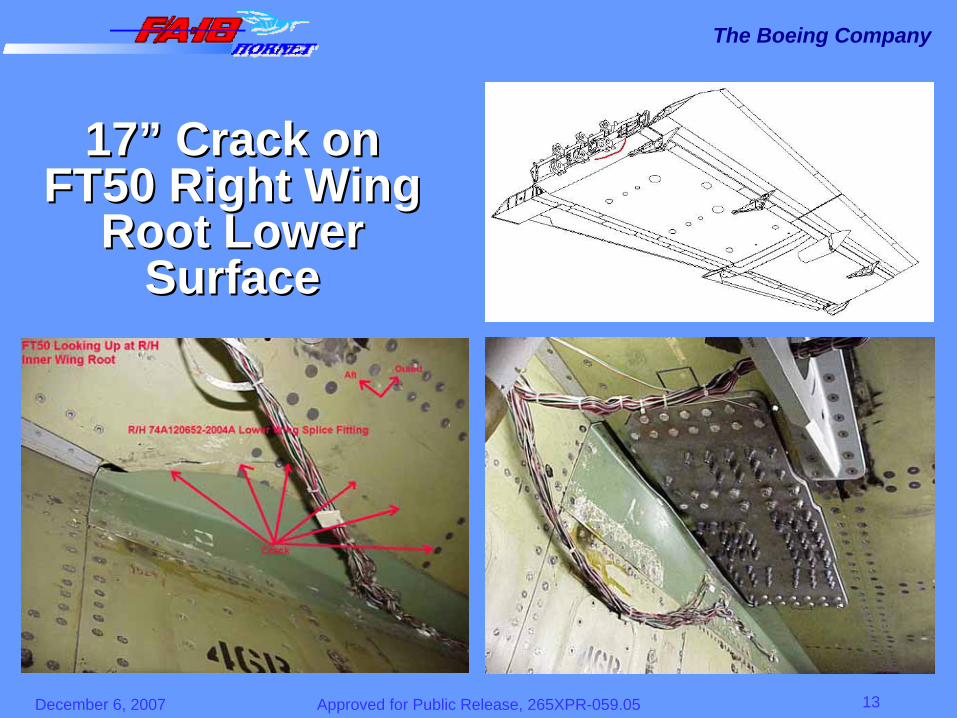
1717”” Crack on Crack on FT50 Right Wing FT50 Right Wing
Root Lower Root Lower SurfaceSurface
Approved for Public Release, 265XPR-059.05 14December 6, 2007
The Boeing Company
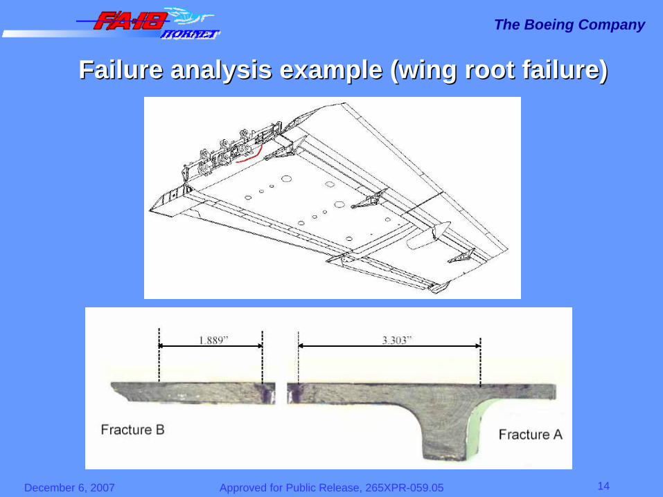
Failure analysis example (wing root failure)Failure analysis example (wing root failure)
Approved for Public Release, 265XPR-059.05 15December 6, 2007
The Boeing Company
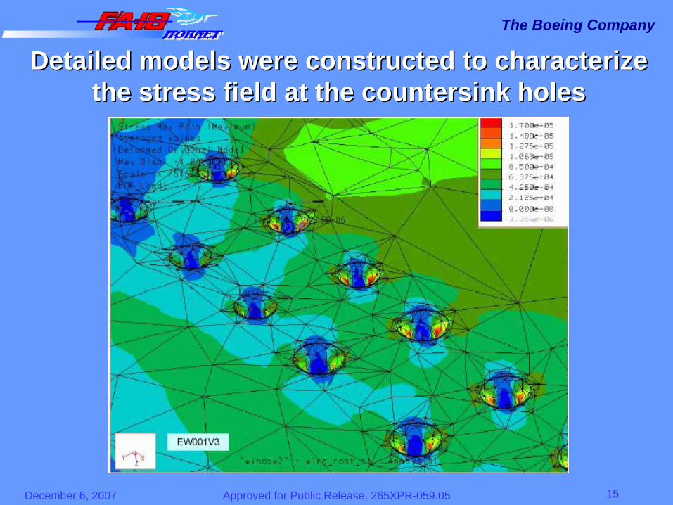
Detailed models were constructed to characterize Detailed models were constructed to characterize the stress field at the countersink holesthe stress field at the countersink holes
Approved for Public Release, 265XPR-059.05 16December 6, 2007
The Boeing Company
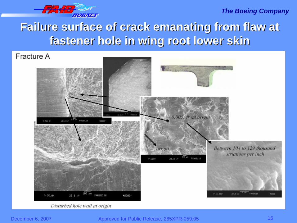
Failure surface of crack emanating from flaw at Failure surface of crack emanating from flaw at fastener hole in wing root lower skinfastener hole in wing root lower skin
Approved for Public Release, 265XPR-059.05 17December 6, 2007
The Boeing Company
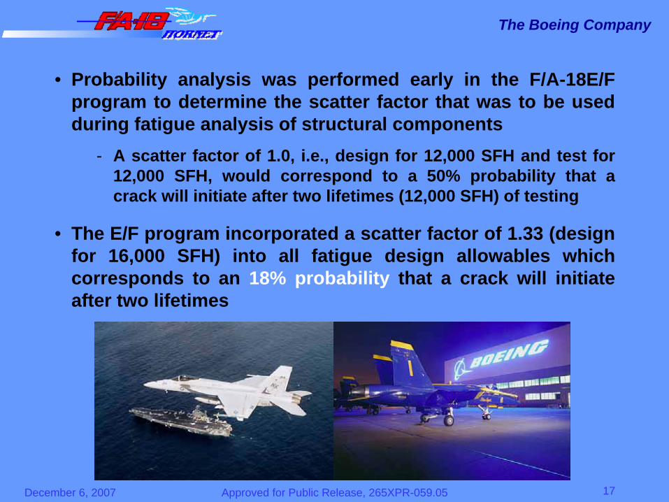
• Probability analysis was performed early in the F/A-18E/F program to determine the scatter factor that was to be used during fatigue analysis of structural components
- A scatter factor of 1.0, i.e., design for 12,000 SFH and test for 12,000 SFH, would correspond to a 50% probability that a crack will initiate after two lifetimes (12,000 SFH) of testing
• The E/F program incorporated a scatter factor of 1.33 (design for 16,000 SFH) into all fatigue design allowables which corresponds to an 18% probability that a crack will initiate after two lifetimes

Approved for Public Release, 265XPR-059.05 18December 6, 2007
The Boeing Company
• Stretch testing the FT50 test article to three lifetimes (18,000SFH) corresponds to an effective scatter factor of 0.89 since the structure was only designed for 16,000 but was tested for 18,000 SFH
• This scatter factor corresponds to a 65% probability that a crack will initiate after two lifetimes
• Therefore, the number of cracks identified on the FT50 test article is not unexpected

Approved for Public Release, 265XPR-059.05 19December 6, 2007
The Boeing Company
Summary of cracks on FT50Summary of cracks on FT50at completion of 18,000 SFH of testing at completion of 18,000 SFH of testing
FT50 Component Parts TotalWing 43 641
Forward Fuselage 53 492Center Fuselage 133 1119
Aft Fuselage 56 293Mechanisms 2 3Vertical Tail 9 45
Totals --> 296 2593
Crack Summary

Approved for Public Release, 265XPR-059.05 20December 6, 2007
The Boeing Company
Many Parameters Required To Many Parameters Required To Successfully Complete Test ProgramSuccessfully Complete Test Program
Must perform many tasks to achieve a successful test
CertificationCertification
Perform Over/Undertest Analysis
Failure Analysis CapabilityNDI Capability
Analytic Tools
Define Teardown Criteria
Coordinated Teardown PlanCustomer CoordinationStrain SurveysSt
ruct
ural
Tech
nolo
gy
SUCCESS

Approved for Public Release, 265XPR-059.05 21December 6, 2007
The Boeing Company
F/AF/A--18E/F Test Conclusions18E/F Test Conclusions• The F/A-18E/F full-scale fatigue test programs are a solid
success as expressed by United States Navy– “Superb” technical performance expressed by customer– FT50 2nd lifetime testing completed ahead of schedule
• Comprised multiple full scale fatigue test articles that certified the airframe to meet the intended design life
• Successful in identifying structure that is capable of exceeding the intended design life
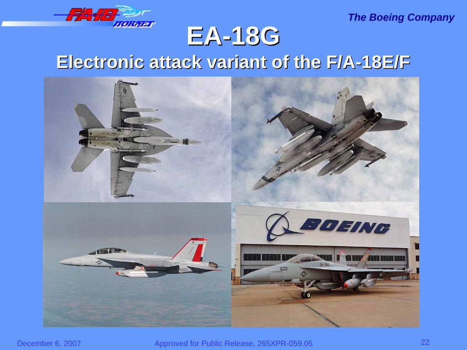
• Success of the F/A-18E/F airframe continues to be realized by utilizing the E/F structural platform as the foundation of the EA-18G program – Next generation of electronic attack aircraft for the United States Navy
Approved for Public Release, 265XPR-059.05 22December 6, 2007
The Boeing Company
EAEA--18G18GElectronic attack variant of the F/AElectronic attack variant of the F/A--18E/F18E/F