FADOS MUX MULTIPLEXER MODULE - protarge.com
7
Transcript of FADOS MUX MULTIPLEXER MODULE - protarge.com
FADOS MUX MULTIPLEXER MODULE
FADOS Multiplexer Module uses for testing and checking electronic circuit boards. The main purposes is
creates VI graphs of circuit board test points in a while. So; the user measure much tests points in a short
time.
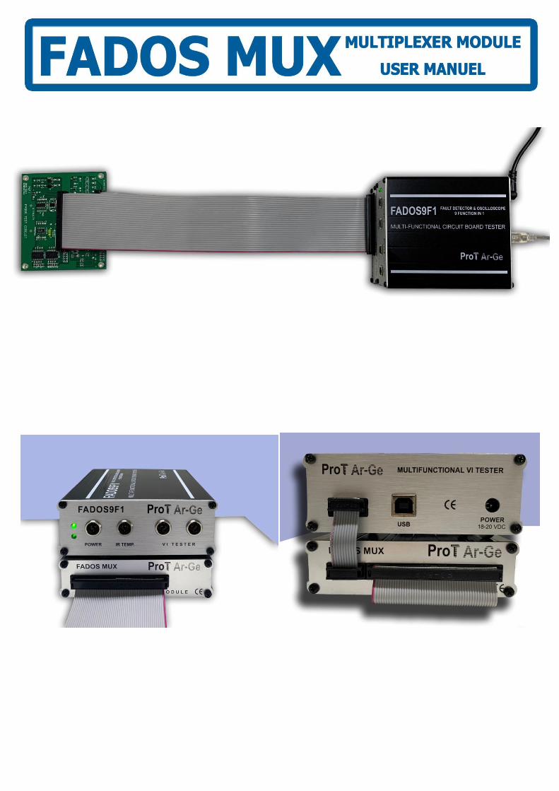
FADOS MUX Multiplexer Module works with FADOS9F1 together. It connects to FADOS9F1 with a connector
and takes energy from FADOS9F1. FADOS MUX has 96 outputs. The first (front) 48 output is “A” channel;
the second (back) 48 output is “B” channel. A - B channels measure at the same time.
FADOS MUX connects parallel to each other so that the output changes according to how many products
connect parallel. For example; if 2 FADOS MUX connect parallel the output is 96 x 2 = 192.
Figure 1 : FADOS MUX Multiplexer Module Connection
FADOS MUX has 3 accessories; A – B channel 50 pin connectors and 10 pin connectors for connection to
FADOS9F1.

The Multiplexer button is clicked in the FADOS9F1 program to open the multiplexer screen.
All the keys to be used for trouble shooting are placed on the left hand side of the panel.
Figure 2 : Multiplexer Screen

Voltage, Frequency, Current Selection
The Multiplexer test voltage stages are ±1.5 V, ±3 V, ±6 V, and ±12 V. The FADOS apply a current-limited
sinusoidal test voltage in the above test voltage values to the point selected on the electronic circuit board
through a series resistor.
VI Test screen is also divided in to squares of the same size. The squares on the horizontal axis provide
information on the voltage ranges.
The Multiplexer current stages are Low Current, Medium1 Current, and Medium2 Current.
The Multiplexer frequency stages are Low Frq, and Test Frq.
Select voltage, current and frequency stages by buttons that are placed on the left hand side of the panel.
Voltage Stage(s) : The voltage to be applied to the board is selected by manually setting
the ±1.5 V, ±3 V, ±6 V, ±12 V stages from the voltage stage selector. Only one voltage may
be selected at a time for a given test.
Frequency Stage(s) : The Frequency to be applied to the board is selected by
manually setting the Low Frequency, Test Frequency, stages from the Frequency stage
selector. Only one Frequency may be selected at a time for a given test.
Current Stage(s) : The current to be applied to the board is selected by manually setting
the Low Current, Medium1 Current, Medium2 Current, stages from the Current stage selector.
Only one Current may be selected at a time for a given test.
Show Pin VI : We can see VI graph of pin which we test or measure.
Ref. Test VI : Show the VI graph of reference pin (saved electronic circuit board)
can measure the internal resistance of the capacitor and determine its quality when this
feature is selected.
Pin : Show the VI graph of pin that measure.
Tolerance % : Defines the tolerance range for the test point. It can be changed by
the user.
Set : Set the voltage, frequency and current stage for testing component.
__ To __ : Shows which datas that checks.
Test Point : Shows the name or code of the point under test.
Reference : Before the data are recorded in the memory, create VI graphs of
reference board from __ pin to __ pin.
Recording : Opens the Recording window. The recording window menu is used for
Recording or retrieving the recorded data.
Test : Test pins from Memory.
Data Form : Shows Mux Data Form.
Clear Table : Clear the table of Mux Data Form.

GENERAL USAGE of MULTIPLEXER INFORMATION
When run software, Power – The IR Temperature Test Screen opens and an input is entered to the
Multiplexer Screen with the Multiplexer Button.
Firstly, determine how many pins that you ll check from __ to __ .
Set the voltage current and frequency of pins.
For example;
Pin1: Select 6V, Test Freq and Med1 Current and click “Set”
Pin2: Select 12V, Test Freq and Med1 Current and click “Set”
Pin3: Select 6V, Test Freq and Low Current and click “Set”
Also we Set the “Tolerance”
Every data be able to see in Mux Data table.
Figure 3 : Set Voltage, Current, Frequency
Note: Mux data table is moveable; you can move it as you want from top bar part according to resolution
of screen especially for low resolution.
After Set the Voltage, Current, Freq and Tolerance; click “Reference” for creating VI graph of
electronic pins. Wait a while for ”REFERENCE OK”
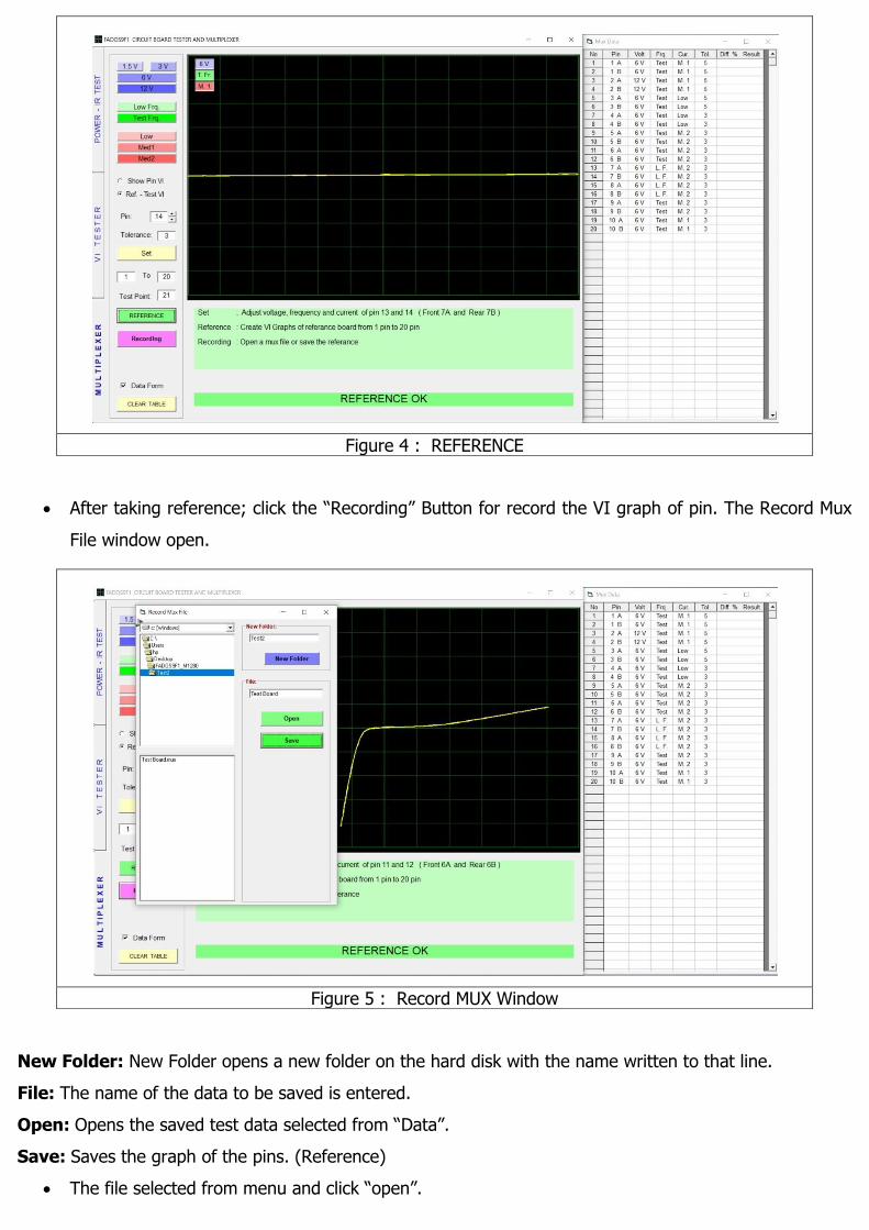
Figure 4 : REFERENCE
After taking reference; click the “Recording” Button for record the VI graph of pin. The Record Mux
File window open.
Figure 5 : Record MUX Window
New Folder: New Folder opens a new folder on the hard disk with the name written to that line.
File: The name of the data to be saved is entered.
Open: Opens the saved test data selected from “Data”.
Save: Saves the graph of the pins. (Reference)
The file selected from menu and click “open”.
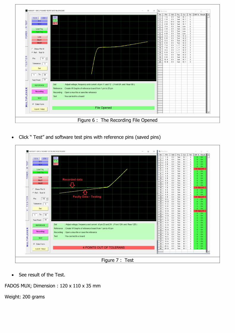
Figure 6 : The Recording File Opened
Click “ Test” and software test pins with reference pins (saved pins)
Figure 7 : Test
See result of the Test.
FADOS MUX; Dimension : 120 x 110 x 35 mm
Weight: 200 grams