Fadei Komarov Alexander Kamyshan - INFN€¦ · The phenomenon of glancing motion of ion beams...
37
[email protected] Fadei Komarov Alexander Kamyshan Institute of Applied Physics Problems, Belarusian State University, Minsk, Belarus CHANNELING-2010
Transcript of Fadei Komarov Alexander Kamyshan - INFN€¦ · The phenomenon of glancing motion of ion beams...

Fadei Komarov
Alexander Kamyshan
Institute of Applied Physics Problems, Belarusian State
University, Minsk, Belarus
CHANNELING-2010

10/11/10 CHANNELING-2010
2 Tasks and Objects
Introduction and motivation
Experimental setup designed for studying the
transmission of swift ions through capillary
systems
Micro- and nanocapillary systems
Transmission of swift protons through tapered
micro- and nanocapillaries

10/11/10 CHANNELING-2010
3
Transport of charge particle beams through dielectric capillaries
The principle of new optics discussed in this report is based on interaction of glancing beams of charged particles with a charged insulating surface of capillary walls. To a certain degree, it resembles us the motion of charged particles in channeling regimes along the low-index directions of crystal lattices, or quanta motion in the waveguide regime.
Introduction and Motivation

10/11/10 CHANNELING-2010
4
Potential implementations of the phenomenon
Analysis of the effect of surface charge on the character of
motion of the ion beam forming this charge on an insulator is of interest both for new ion optics and for analysis of the
interaction of particles with insulators at small angles of beam incidence with respect to the surface.
The phenomenon of glancing motion of ion beams along a charged dielectric surface can be used to develop systems
of transformation, control, and transport of charged particle
beams; in particular, to obtain micro- and nanosized beams, which are interesting in local elemental and structural
analysis, nanolithography, X-Ray radiography and applications in biology and medicine.
Introduction and Motivation
10/11/10 CHANNELING-2010
5
Potential implementations of the phenomenon
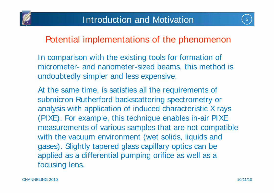
In comparison with the existing tools for formation of micrometer- and nanometer-sized beams, this method is undoubtedly simpler and less expensive.
At the same time, is satisfies all the requirements of
submicron Rutherford backscattering spectrometry or analysis with application of induced characteristic X rays (PIXE). For example, this technique enables in-air PIXE measurements of various samples that are not compatible with the vacuum environment (wet solids, liquids and gases). Slightly tapered glass capillary optics can be applied as a differential pumping orifice as well as a focusing lens.
Introduction and Motivation

10/11/10 CHANNELING-2010
6 Capillary systems based on ion tracks
Fabrication of nanocapillaries in polymers
As a unprecedented result on the low energy ion transmission through such capillaries I illustrate an experiment of N.
Stolterfoht et al., NIM B203 (2003) 246.
They measured the transmission of 3 keV Ne7+ ions through
capillaries of 100 nm diameter and 10 m length produced by etching ion tracks in a polyethylene terephthalate polymer foil. The foils were tilted up to ±25°. The majority of Ne7+ ions were
found to survive the transmission in their initial charge. This capillary guiding of the Ne7+ ion provides evidence that the
inner walls of the capillaries become charged and electron capture from the surface is suppressed in a self-organizing process.

10/11/10 CHANNELING-2010
7 Capillary systems based on ion tracks
A beam of 1.3 nA Ne7+ ions is directed onto the
PET foil tilted at 10°.
The transmitted Ne7+
intensity measured at 10° increases exponentially
with a time constant of 2.5 min. After 10 min the beam is turned off. Short
beam pulses probe the decrease of the
transmission with a time constant of 40 min.
Time dependence of the transmitted Ne7+ intensity showing the
charging and discharging phenomena of capillaries in PET

10/11/10 CHANNELING-2010
8 Experimental Setup
Schematic of the experimental setup: (MC) matching circuit, (VFC) voltage-frequency
converter, (VD) voltage divider, (EA) electrometric amplifier, (FVC) frequency-voltage
converter, (RM) programmable rate meter, (FA) forming amplifier, (CSP) chargesensitive
preamplifier, (SBD) silicon surface barrier detector, and (PC) personal computer.

10/11/10 CHANNELING-2010
9 Experimental Setup
Analytical equipment to study processes of charged
particle interaction with capillary systems
10/11/10 CHANNELING-2010
10 Experimental Setup
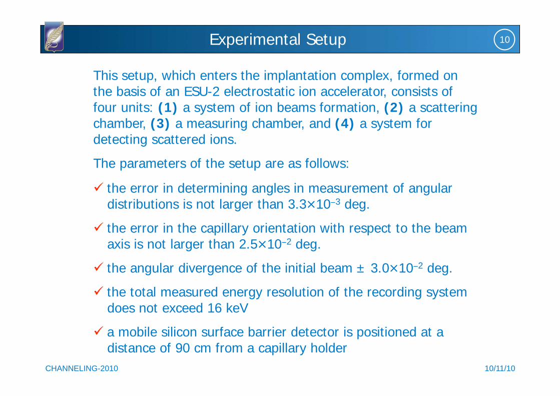
This setup, which enters the implantation complex, formed on the basis of an ESU-2 electrostatic ion accelerator, consists of four units: (1) a system of ion beams formation, (2) a scattering chamber, (3) a measuring chamber, and (4) a system for detecting scattered ions.
The parameters of the setup are as follows:
the error in determining angles in measurement of angular distributions is not larger than 3.3 10 3 deg.
the error in the capillary orientation with respect to the beam axis is not larger than 2.5 10 2 deg.
the angular divergence of the initial beam ± 3.0 10 2 deg.
the total measured energy resolution of the recording system does not exceed 16 keV
a mobile silicon surface barrier detector is positioned at a distance of 90 cm from a capillary holder
10/11/10 CHANNELING-2010
11 Micro and nanocapillary systems
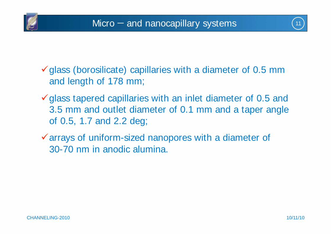
glass (borosilicate) capillaries with a diameter of 0.5 mm and length of 178 mm;
glass tapered capillaries with an inlet diameter of 0.5 and 3.5 mm and outlet diameter of 0.1 mm and a taper angle of 0.5, 1.7 and 2.2 deg;
arrays of uniform-sized nanopores with a diameter of
30-70 nm in anodic alumina.

10/11/10 CHANNELING-2010
12
The individual capillary systems used for the transportation of
proton beams
Micro and nanocapillary systems
10/11/10 CHANNELING-2010
13 Transmission of proton beams
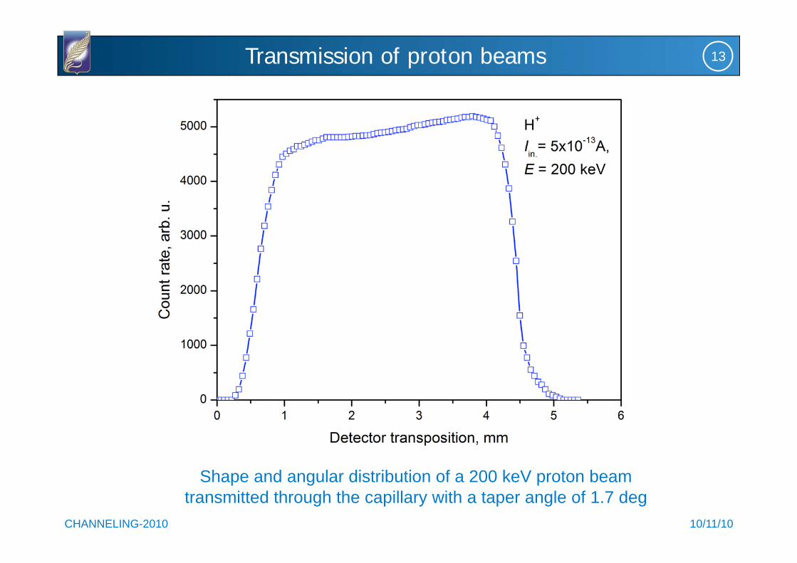
Shape and angular distribution of a 200 keV proton beam
transmitted through the capillary with a taper angle of 1.7 deg
10/11/10 CHANNELING-2010
14 Transmission of proton beams
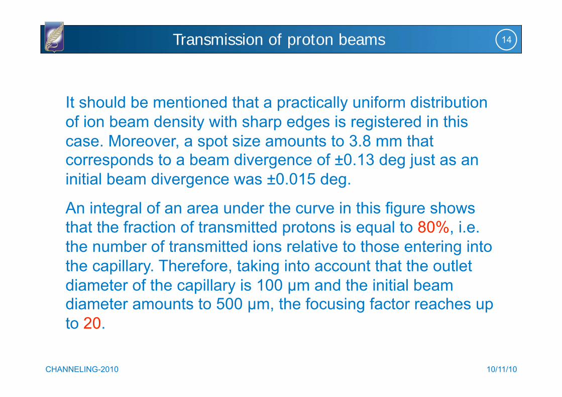
It should be mentioned that a practically uniform distribution
of ion beam density with sharp edges is registered in this
case. Moreover, a spot size amounts to 3.8 mm that corresponds to a beam divergence of ±0.13 deg just as an
initial beam divergence was ±0.015 deg.
An integral of an area under the curve in this figure shows
that the fraction of transmitted protons is equal to 80%, i.e.
the number of transmitted ions relative to those entering into
the capillary. Therefore, taking into account that the outlet
diameter of the capillary is 100 μm and the initial beam diameter amounts to 500 μm, the focusing factor reaches up
to 20.

10/11/10 CHANNELING-2010
15
Count rate of particles transmitted through the capillary versus
proton current at the input of the capillary
Transmission of proton beams
10/11/10 CHANNELING-2010
16 Transmission of proton beams
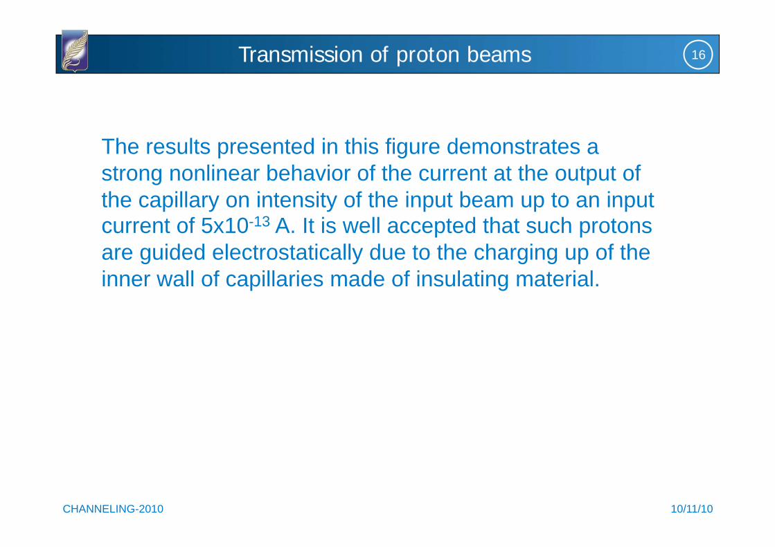
The results presented in this figure demonstrates a
strong nonlinear behavior of the current at the output of
the capillary on intensity of the input beam up to an input current of 5x10-13 A. It is well accepted that such protons
are guided electrostatically due to the charging up of the
inner wall of capillaries made of insulating material.

10/11/10 CHANNELING-2010
17
Time distributions of protons transmitted through a tapered
capillary (a) and cylindrical capillary (b)
Transmission of proton beams

10/11/10 CHANNELING-2010
18 Transmission of proton beams
In spite of the practically equal currents at the input of these
capillaries, time evolutions of beam currents at the output of
the capillaries are strongly different in shapes and frequencies of the beam intensity oscillations. Current pulse frequencies of
ions transmitted through the tapered capillary exceed
essentially those for the cylindrical capillary. On the contrary,
more shorter pulse durations are typical for the tapered
capillary.
The mentioned above experimental results confirm our recent
assumption on a dominant role of charging up a face part of the capillary in the transformation of continuous ion beams into
oscillating ones. This effect is not observed if an input hole of
capillaries exceeds the beam diameter.
10/11/10 CHANNELING-2010
19
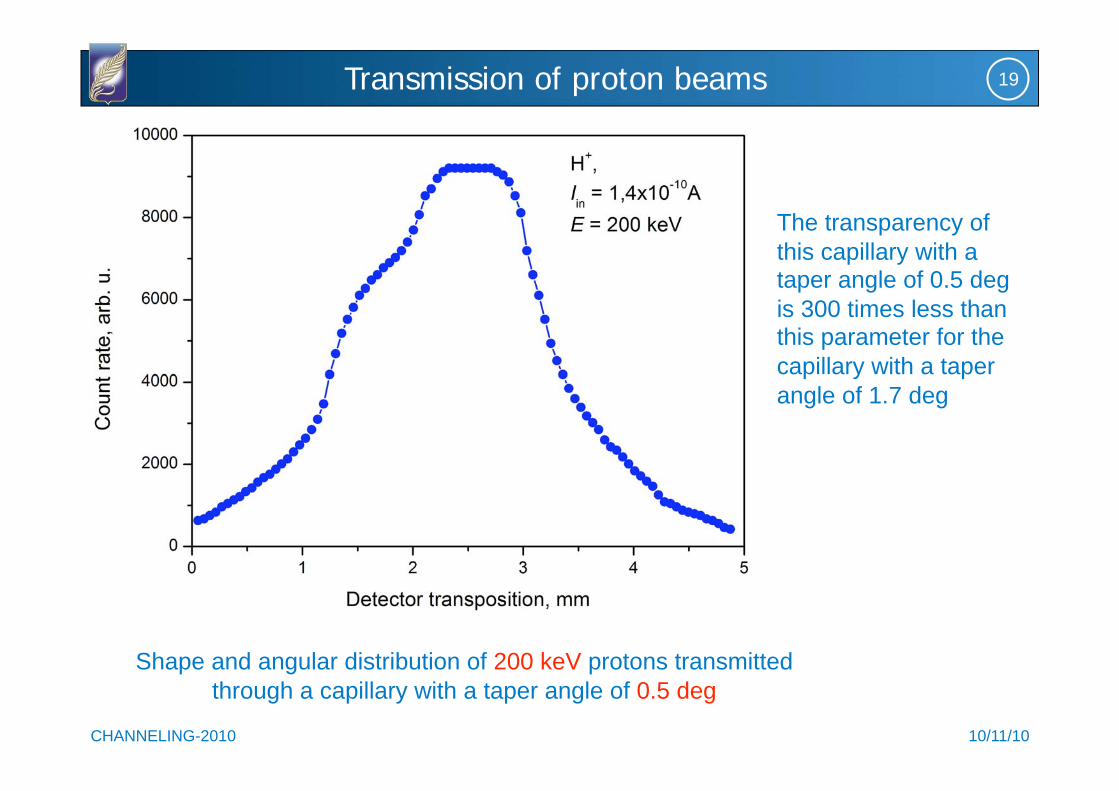
Shape and angular distribution of 200 keV protons transmitted
through a capillary with a taper angle of 0.5 deg
Transmission of proton beams
The transparency of
this capillary with a taper angle of 0.5 deg
is 300 times less than this parameter for the
capillary with a taper
angle of 1.7 deg

10/11/10 CHANNELING-2010
20
Angular distribution of 320 keV protons transmitted through a
capillary with a taper angle of 2.2 deg
Transmission of proton beams

10/11/10 CHANNELING-2010
21
Energy spectrum of transmitted protons with an initial energy of 320 keV
with and without capillary. The taper angle is 1.7 deg. Curve 1 is for the initial beam and curve 2 is for the transmitted beam
Transmission of proton beams
10/11/10 CHANNELING-2010
22 Transmission of proton beams
The most of ions transmit the capillary without energy loss,
however, the low energy tail certainly exists (curve 2). It
means that those transmitted ions moving with higher transverse energies and suffering the small angle scattering
lose their energy interacting with an inner surface of the
capillary. It should be noted that these particles cause only a
very modest widening of the initial energy distribution (less
than 5 to 6%).

10/11/10 CHANNELING-2010
23
Diameters of entrance holes on the face side of the sample. The thickness of anodic
alumina wafers was 42 μm. Diameter of entrance holes was in a range of 60-70 nm and the density of holes was 1.2x1010 cm-2
Transmission of proton beams The image cannot be displayed. Your computer may not have enough memory to open the image, or the image may have been corrupted. Restart your computer, and then open the file again. If the red x still appears, you may have to delete the image and then insert it again.
10/11/10 CHANNELING-2010
24
SEM cross-section images of a cleaved sample
Transmission of proton beams
The image cannot be displayed. Your computer may not have enough memory to open the image, or the image may have been corrupted. Restart your computer, and then open the file again. If the red x still appears, you may have to delete the image and then insert it again.

10/11/10 CHANNELING-2010
25
Angular distribution of protons with an energy of 190 keV transmitted
through the Al2O3 nanostructure sample oriented along the beam axis
Transmission of proton beams

10/11/10 CHANNELING-2010
26
Angular distribution of protons with energy of 290 keV transmitted
through the Al2O3 nanostructure sample oriented along the beam axis
Transmission of proton beams

10/11/10 CHANNELING-2010
27
Angular distribution of 290 keV protons transmitted through the
Al2O3 sample at a misorientation angle of 0.07 deg
Transmission of proton beams

10/11/10 CHANNELING-2010
28
It should be noted that the FWHM of central peaks in the both
angular distributions is considerably narrower than the width of the
initial beam.
The presented in the last three figures proton beam intensities were
measured behind the sample with a thickness of 42 μm that
considerably (more than one order of magnitude) exceeds ranges
of protons in this material.
This is an evidence of an anomalous motion of protons like the
hyperchanneling of charged particles along the low-index directions
of crystal lattices. The transmission coefficient in this system
achieved a few percent if the face part of the sample was covered
with a thin Au layer.
Transmission of proton beams

10/11/10 CHANNELING-2010
29
The Kumakhov s
microcapillary system with a diameter of 30 nm of individual glass capillaries
Micro and nanocapillary systems

10/11/10 CHANNELING-2010
30 Application of capillary ion optics
(A) the glass capillary optics, (B) the X-ray detector, (C) the sea water droplet
The image cannot be displayed. Your computer may not have enough memory to open the image, or the image may have been corrupted. Restart your computer, and then open the file again. If the red x still appears, you may have to delete the image and then insert it again.

10/11/10 CHANNELING-2010
31 Application of capillary ion optics
PIXE spectrum of sea water
The image cannot be displayed. Your computer may not have enough memory to open the image, or the image may have been corrupted. Restart your computer, and then open the file again. If the red x still appears, you may have to delete the image and then insert it again.

10/11/10 CHANNELING-2010
32
External PIXE spectrum of a gallbladder tissue
Application of capillary ion optics

10/11/10 CHANNELING-2010
33 Application of capillary ion optics
The experimental setup for micro-beam production using a tapered
glass capillary (J. Hasegawa et al., NIM B 266 (2008) 2125)
The image cannot be displayed. Your computer may not have enough memory to open the image, or the image may have been corrupted. Restart your computer, and then open the file again. If the red x still appears, you may have to delete the image and then insert it again.

10/11/10 CHANNELING-2010
34 Proton-induced X-ray radiography
A schematic of quasi-monochromatic X-ray imaging using the glass-
capillary-based micro-beam generator
The image cannot be displayed. Your computer may not have enough memory to open the image, or the image may have been corrupted. Restart your computer, and then open the file again. If the red x still appears, you may have to delete the image and then insert it again.

10/11/10 CHANNELING-2010
35 Application of capillary ion optics
An image of a miniature bulb filament taken by Cu K X-rays.
Capillary tip: D 25 m, exposure time: 1 h, magnification: 10x
(J. Hasegawa et al., NIM B 266 (2008) 2125)
The image cannot be displayed. Your computer may not have enough memory to open the image, or the image may have been corrupted. Restart your computer, and then open the file again. If the red x still appears, you may have to delete the image and then insert it again.

10/11/10 CHANNELING-2010
36 Summarizing
We have confirmed that a few hundred keV proton beams are
successfully focused by the tapered capillary optics.
The areal density of the transmitted beam is enhanced by approximately
20 times.
Charging up a face part of the capillary causes the transformation of
continues ion beams to oscillating ones.
The most of protons (94–95%) in the energy range of 150 to 320 keV
transmit the capillary without energy loss.
Changing a taper angle from 0.5 deg to 1.7 deg evidences increase of
the transmission coefficient more than by 300 times keeping the initial energy spectrum of ions.
Compared with the conventional micro-beam facilities, the usage of tapered capillaries is certainly simple and low-cost, thus providing an
interesting technique of submicron RBS or PIXE elemental analyses. Moreover, if the ion species are extended to heavier elements, the
present method provides highly local versatile maskless ion implantation
technique.

10/11/10 CHANNELING-2010
37 Summarizing


![(eBook - PDF)[Fisica][Astronomia] Komarov v - Nueva Astronomía Recreativa (Editorial Mir)](https://static.fdocuments.us/doc/165x107/577cc7231a28aba711a014ee/ebook-pdffisicaastronomia-komarov-v-nueva-astronomia-recreativa.jpg)