
FACTORY AUTOMATION -...
56
FACTORY AUTOMATION Manual Absolute rotary encoder P**58 PROFIBUS interface
Transcript of FACTORY AUTOMATION -...

FACT
ORY
AUTO
MAT
ION
Manual
Absolute rotary encoder P**58
PROFIBUS interface

With regard to the supply of products, the current issue of the following document is applicable:The General Terms of Delivery for Products and Services of the Electrical Industry, as published by
the Central Association of the "Elektrotechnik und Elektroindustrie (ZVEI) e.V.", including the supplementary clause "Extended reservation of title".
We at Pepperl+Fuchs recognize a duty to make a contribution to the future.For this reason, this printed matter is produced on paper bleached without the use of chlorine.

Absolute rotary encoder P**58Table of contents
Subject to reasonable modifications due to technical advances. Copyright Pepperl+Fuchs, Printed in Germany
Pepperl+Fuchs Group • Tel.: Germany +49 621 776-0 • USA +1 330 4253555 • Singapore +65 67799091 • Internet http://www.pepperl-fuchs.com
Dat
e of
issu
e01
/15/
04
1
1 General . . . . . . . . . . . . . . . . . . . . . . . . . . . . . . . . . . . . . . . . . . . . . . . . . . .41.1 Declaration of conformity . . . . . . . . . . . . . . . . . . . . . . . . . . . . . . . . . . . . . . . . . . 4
1.2 Working principle . . . . . . . . . . . . . . . . . . . . . . . . . . . . . . . . . . . . . . . . . . . . . . . . . 4
1.3 PROFIBUS technology . . . . . . . . . . . . . . . . . . . . . . . . . . . . . . . . . . . . . . . . . . . . . 5
1.4 Symbols used . . . . . . . . . . . . . . . . . . . . . . . . . . . . . . . . . . . . . . . . . . . . . . . . . . . . 5
2 Installation . . . . . . . . . . . . . . . . . . . . . . . . . . . . . . . . . . . . . . . . . . . . . . . .62.1 Settings in the connection hood . . . . . . . . . . . . . . . . . . . . . . . . . . . . . . . . . . . . . 62.1.1 Member address . . . . . . . . . . . . . . . . . . . . . . . . . . . . . . . . . . . . . . . . . . . . . . . . . . 62.1.2 Bus terminator . . . . . . . . . . . . . . . . . . . . . . . . . . . . . . . . . . . . . . . . . . . . . . . . . . . . 6
2.2 Connection of signal and power supply lines . . . . . . . . . . . . . . . . . . . . . . . . . . 7
2.3 Wiring of connection hood . . . . . . . . . . . . . . . . . . . . . . . . . . . . . . . . . . . . . . . . . 8
2.4 Connecting the screen line . . . . . . . . . . . . . . . . . . . . . . . . . . . . . . . . . . . . . . . . . 8
2.5 Notes on mechanical fitting and the electrical connection . . . . . . . . . . . . . . . 8
3 Device configuration . . . . . . . . . . . . . . . . . . . . . . . . . . . . . . . . . . . . . .103.1 Principle of data transfer . . . . . . . . . . . . . . . . . . . . . . . . . . . . . . . . . . . . . . . . . . 10
3.2 Overview of encoder classes – functionality . . . . . . . . . . . . . . . . . . . . . . . . . . 11
3.3 Overview of encoder classes – data format . . . . . . . . . . . . . . . . . . . . . . . . . . 12
4 Encoder classes of the PROFIBUS user organisation . . . . . . . . . . .134.1 Parameter assignment . . . . . . . . . . . . . . . . . . . . . . . . . . . . . . . . . . . . . . . . . . . . 134.1.1 Direction of rotation . . . . . . . . . . . . . . . . . . . . . . . . . . . . . . . . . . . . . . . . . . . . . . . 134.1.2 Class 2 functionality . . . . . . . . . . . . . . . . . . . . . . . . . . . . . . . . . . . . . . . . . . . . . . . 144.1.3 Commissioning diagnostics . . . . . . . . . . . . . . . . . . . . . . . . . . . . . . . . . . . . . . . . . 144.1.4 Scaling function . . . . . . . . . . . . . . . . . . . . . . . . . . . . . . . . . . . . . . . . . . . . . . . . . . 144.1.5 Measurement steps per revolution . . . . . . . . . . . . . . . . . . . . . . . . . . . . . . . . . . . . 144.1.6 Overall resolution . . . . . . . . . . . . . . . . . . . . . . . . . . . . . . . . . . . . . . . . . . . . . . . . . 15
4.2 Data exchange in normal operation . . . . . . . . . . . . . . . . . . . . . . . . . . . . . . . . . 154.2.1 Transferring the actual process value . . . . . . . . . . . . . . . . . . . . . . . . . . . . . . . . . 164.2.2 Preset function . . . . . . . . . . . . . . . . . . . . . . . . . . . . . . . . . . . . . . . . . . . . . . . . . . . 16
5 Manufacturer specific encoder classes . . . . . . . . . . . . . . . . . . . . . . .175.1 Parameters . . . . . . . . . . . . . . . . . . . . . . . . . . . . . . . . . . . . . . . . . . . . . . . . . . . . . 185.1.1 Activation of manufacturer specific parameters . . . . . . . . . . . . . . . . . . . . . . . . . . 185.1.2 Desired measurement steps . . . . . . . . . . . . . . . . . . . . . . . . . . . . . . . . . . . . . . . . 185.1.3 Resolution reference . . . . . . . . . . . . . . . . . . . . . . . . . . . . . . . . . . . . . . . . . . . . . . 195.1.4 Activate commissioning mode . . . . . . . . . . . . . . . . . . . . . . . . . . . . . . . . . . . . . . . 205.1.5 Reduced diagnostics . . . . . . . . . . . . . . . . . . . . . . . . . . . . . . . . . . . . . . . . . . . . . . 205.1.6 Software limit switches . . . . . . . . . . . . . . . . . . . . . . . . . . . . . . . . . . . . . . . . . . . . . 205.1.7 Physical measurement steps . . . . . . . . . . . . . . . . . . . . . . . . . . . . . . . . . . . . . . . . 215.1.8 Rotary encoder type . . . . . . . . . . . . . . . . . . . . . . . . . . . . . . . . . . . . . . . . . . . . . . . 225.1.9 Unit of measure for speed . . . . . . . . . . . . . . . . . . . . . . . . . . . . . . . . . . . . . . . . . . 22
5.2 Data exchange in normal mode . . . . . . . . . . . . . . . . . . . . . . . . . . . . . . . . . . . . 23

Absolute rotary encoder P**58Table of contents
Subject to reasonable modifications due to technical advances. Copyright Pepperl+Fuchs, Printed in Germany
Pepperl+Fuchs Group • Tel.: Germany +49 621 776-0 • USA +1 330 4253555 • Singapore +65 67799091 • Internet http://www.pepperl-fuchs.com
Dat
e of
issu
e01
/15/
04
2
5.3 Commissioning mode . . . . . . . . . . . . . . . . . . . . . . . . . . . . . . . . . . . . . . . . . . . . . 245.3.1 Setting the direction of rotation . . . . . . . . . . . . . . . . . . . . . . . . . . . . . . . . . . . . . . . 245.3.2 TEACH-IN start . . . . . . . . . . . . . . . . . . . . . . . . . . . . . . . . . . . . . . . . . . . . . . . . . . . 255.3.3 TEACH-IN stop . . . . . . . . . . . . . . . . . . . . . . . . . . . . . . . . . . . . . . . . . . . . . . . . . . . 255.3.4 Preset value . . . . . . . . . . . . . . . . . . . . . . . . . . . . . . . . . . . . . . . . . . . . . . . . . . . . . . 26
6 Diagnostic messages . . . . . . . . . . . . . . . . . . . . . . . . . . . . . . . . . . . . . . 276.1 Overview . . . . . . . . . . . . . . . . . . . . . . . . . . . . . . . . . . . . . . . . . . . . . . . . . . . . . . . . 27
6.2 Supported diagnostic messages . . . . . . . . . . . . . . . . . . . . . . . . . . . . . . . . . . . . 286.2.1 Advanced diagnostics header . . . . . . . . . . . . . . . . . . . . . . . . . . . . . . . . . . . . . . . . 286.2.2 Memory error . . . . . . . . . . . . . . . . . . . . . . . . . . . . . . . . . . . . . . . . . . . . . . . . . . . . . 286.2.3 Operating status . . . . . . . . . . . . . . . . . . . . . . . . . . . . . . . . . . . . . . . . . . . . . . . . . . 286.2.4 Rotary encoder type . . . . . . . . . . . . . . . . . . . . . . . . . . . . . . . . . . . . . . . . . . . . . . . 286.2.5 Singleturn resolution . . . . . . . . . . . . . . . . . . . . . . . . . . . . . . . . . . . . . . . . . . . . . . . 286.2.6 Number of revolutions . . . . . . . . . . . . . . . . . . . . . . . . . . . . . . . . . . . . . . . . . . . . . . 286.2.7 Operating time warning . . . . . . . . . . . . . . . . . . . . . . . . . . . . . . . . . . . . . . . . . . . . . 286.2.8 Profile version . . . . . . . . . . . . . . . . . . . . . . . . . . . . . . . . . . . . . . . . . . . . . . . . . . . .296.2.9 Software version . . . . . . . . . . . . . . . . . . . . . . . . . . . . . . . . . . . . . . . . . . . . . . . . . . 296.2.10 Operating time . . . . . . . . . . . . . . . . . . . . . . . . . . . . . . . . . . . . . . . . . . . . . . . . . . . . 296.2.11 Reference point shift . . . . . . . . . . . . . . . . . . . . . . . . . . . . . . . . . . . . . . . . . . . . . . . 296.2.12 Resolution as assigned by parameter . . . . . . . . . . . . . . . . . . . . . . . . . . . . . . . . . . 296.2.13 Overall resolution as assigned by parameter . . . . . . . . . . . . . . . . . . . . . . . . . . . . 296.2.14 Serial number . . . . . . . . . . . . . . . . . . . . . . . . . . . . . . . . . . . . . . . . . . . . . . . . . . . .29
6.3 Status information of LEDs . . . . . . . . . . . . . . . . . . . . . . . . . . . . . . . . . . . . . . . . 30
7 Sample configuration . . . . . . . . . . . . . . . . . . . . . . . . . . . . . . . . . . . . . . 317.1 Reading the GSD file . . . . . . . . . . . . . . . . . . . . . . . . . . . . . . . . . . . . . . . . . . . . . . 31
7.2 Projecting the rotary encoder . . . . . . . . . . . . . . . . . . . . . . . . . . . . . . . . . . . . . . . 32
7.3 Selecting the device class . . . . . . . . . . . . . . . . . . . . . . . . . . . . . . . . . . . . . . . . . 33
7.4 Parameter assignment . . . . . . . . . . . . . . . . . . . . . . . . . . . . . . . . . . . . . . . . . . . . 34
8 Technical data . . . . . . . . . . . . . . . . . . . . . . . . . . . . . . . . . . . . . . . . . . . . 368.1 Electrical data . . . . . . . . . . . . . . . . . . . . . . . . . . . . . . . . . . . . . . . . . . . . . . . . . . . 36
8.2 Mechanical data . . . . . . . . . . . . . . . . . . . . . . . . . . . . . . . . . . . . . . . . . . . . . . . . . . 36
8.3 Ambient conditions . . . . . . . . . . . . . . . . . . . . . . . . . . . . . . . . . . . . . . . . . . . . . . . 37
8.4 Dimensional drawings . . . . . . . . . . . . . . . . . . . . . . . . . . . . . . . . . . . . . . . . . . . . . 388.4.1 Rotary encoder with servo flange . . . . . . . . . . . . . . . . . . . . . . . . . . . . . . . . . . . . . 388.4.2 Rotary encoder with clamp flange . . . . . . . . . . . . . . . . . . . . . . . . . . . . . . . . . . . . . 398.4.3 Rotary encoder with recessed hollow shaft . . . . . . . . . . . . . . . . . . . . . . . . . . . . . . 40
9 Appendix . . . . . . . . . . . . . . . . . . . . . . . . . . . . . . . . . . . . . . . . . . . . . . . . 419.1 Type code, model number . . . . . . . . . . . . . . . . . . . . . . . . . . . . . . . . . . . . . . . . . 41
9.2 Troubleshooting . . . . . . . . . . . . . . . . . . . . . . . . . . . . . . . . . . . . . . . . . . . . . . . . . 42
9.3 Terms . . . . . . . . . . . . . . . . . . . . . . . . . . . . . . . . . . . . . . . . . . . . . . . . . . . . . . . . . . 44
10 Index . . . . . . . . . . . . . . . . . . . . . . . . . . . . . . . . . . . . . . . . . . . . . . . . . . . 46

Absolute rotary encoder P**58Indroduction
Subject to reasonable modifications due to technical advances. Copyright Pepperl+Fuchs, Printed in Germany
Pepperl+Fuchs Group • Tel.: Germany +49 621 776-0 • USA +1 330 4253555 • Singapore +65 67799091 • Internet http://www.pepperl-fuchs.com
Dat
e of
issu
e01
/15/
04
3
Indroduction
Impressum
Pepperl+Fuchs
Königsberger Allee 87
D-68307 Mannheim
Phone +49 621 776-0
Internet www.pepperl-fuchs.com
Fax +49 621 776-1000
E-mail [email protected]
Copyright
All rights for this documentation reserved by Pepperl+Fuchs GmbH. This documentation must not be modified, expanded, duplicated or passed on to third parties without prior written consent of Pepperl+Fuchs GmbH.
Subject to modification
Because we are constantly striving to improve our products, we reserve the right to make resulting technical modifications to the technical information included in this document at any time.
Document information
Filename: PROFIBUS manual
Release date: 01/2004
Version number: 3.0
Editor: Rainer Russ
Service phone number
We will be happy to assist you with technical support, questions and suggestions for improving our products and documentation. Please call +49 7461-9298-0.

Absolute rotary encoder P**58General
Subject to reasonable modifications due to technical advances. Copyright Pepperl+Fuchs, Printed in Germany
Pepperl+Fuchs Group • Tel.: Germany +49 621 776-0 • USA +1 330 4253555 • Singapore +65 67799091 • Internet http://www.pepperl-fuchs.com
Dat
e of
issu
e01
/15/
04
4
1 General
This manual describes commissioning and configuration of the absolute rotary encoder with PROFIBUS DP interface. The device satisfies requirements for a PROFIBUS slave according to the PROFIBUS standard and is certified by the PROFIBUS user organisation.
1.1 Declaration of conformity
Absolute rotary encoders of Series P**58 are developed and manufactured taking into consideration applicable European standards and directives.
The manufacturer of the product, Pepperl+Fuchs GmbH in D-68301 Mannheim, has a certified quality assurance program in accordane with ISO 9001.
1.2 Working principle
The basic principle of recording absolute measurement values is optical sensing of a transparent disk with a printed code that is connected to the shaft to be measured. The position of the shaft can be determined by evaluating the code at a resolution of up to 65,536 increments or "steps" per revolution (16 bits).
In the case of Multiturn devices, additional code disks can be included in the circuit with ratio reduction gears, which can be used to determine the absolute rotation speed of the shaft (up to 16,384 revolutions = 14 bits).
In the case of an absolute rotary encoder with a PROFIBUS interface, the optically recorded position value is calculated in an integrated microprocessor and is transferred with the PROFIBUS.
A corresponding declaration of conformity may be requested from the manufacturer.
Note
ISO9001

Absolute rotary encoder P**58General
Subject to reasonable modifications due to technical advances. Copyright Pepperl+Fuchs, Printed in Germany
Pepperl+Fuchs Group • Tel.: Germany +49 621 776-0 • USA +1 330 4253555 • Singapore +65 67799091 • Internet http://www.pepperl-fuchs.com
Dat
e of
issu
e01
/15/
04
5
1.3 PROFIBUS technology
PROFIBUS is a manufacturer independent, open fieldbus standard specified by international standards EN 50170 and EN 50254. There are 3 versions: DP, FMS and PA. The rotary encoders support the DP versions and are designed for commonly used transfer rate up to 12 MBaud.
In addition to manufacturer specific functions, the devices support Classes 1 and 2 according to the encoder profile. This device profile can be ordered from the PROFIBUS user organisation with order number 3.062. Additional information on PROFIBUS (functionality, manufacturer and products) as well as standards and profiles are also available here:
PROFIBUS User Organisation
Haid-und-Neu-Strasse 7
76131 Karlsruhe
Tel.: +49 721 9658-590
Fax: +49 721 9658-589
E-mail: www.profibus.com
1.4 Symbols used
This symbol warns of a danger. Failure to heed this warning can lead to personal injury or death and/or damage to or destruction of equipment.
This symbol warns of a possible fault. Failure to observe the instructions given in this warning may result in the device and any facilities or systems connected to it developing a fault or even failing completely.
This symbol draws your attention to important information.
Warning
Attention
Note

Absolute rotary encoder P**58Installation
Subject to reasonable modifications due to technical advances. Copyright Pepperl+Fuchs, Printed in Germany
Pepperl+Fuchs Group • Tel.: Germany +49 621 776-0 • USA +1 330 4253555 • Singapore +65 67799091 • Internet http://www.pepperl-fuchs.com
Dat
e of
issu
e01
/15/
04
6
2 Installation
The connection hood is used to connect the rotary encoder. It is connected with a rotary encoder by means of a 15-pin sub-D plug and can be removed by loosening two screws on the back of the device. Bus and power supply lines are directed into the hood through cable glands and connected with screw terminals.
2.1 Settings in the connection hood
2.1.1 Member address
The PROFIBUS member address can be set with decimal rotary switches in the connection hood. The valency (x 10 or x 1) is specified on the switch. Possible addresses are between 1 and 99. Each address can occur only once in the system. The device address is read in by the rotary encoder when the power supply is turned on. Change of address by the master ("Set_Slave_Add") is not supported.
2.1.2 Bus terminator
If the rotary encoder is fitted as a terminal device, then the terminating resistor that is integrated into the device must be switched into the circuit. This is done with the slide switch in the connection hood:
ONT
ABAB -
x10 x1
+ - +
87
2
6 5 43
09 187
2
6 5 43
09 1
R
ON
RTON
RT
member X last member

Absolute rotary encoder P**58Installation
Subject to reasonable modifications due to technical advances. Copyright Pepperl+Fuchs, Printed in Germany
Pepperl+Fuchs Group • Tel.: Germany +49 621 776-0 • USA +1 330 4253555 • Singapore +65 67799091 • Internet http://www.pepperl-fuchs.com
Dat
e of
issu
e01
/15/
04
7
The bus is not correctly terminated unless the rotary encoder is mounted on the connection hood. If the encoder needs to be replaced while the system is in operation, we recommend using a separate active bus termination.
After the address is set on the hardware side and the power terminating resistor has been switched into the circuit if necessary, the rotary encoder can be placed in operation.
2.2 Connection of signal and power supply lines
When the terminating resistor is turned on, the rest of the bus (Bus Out) is disconnected.
Terminal Explanation
⊥ ground connection for power supply
B (left) data line B (pair 1), Bus In
A (left) data line A (pair 1), Bus In
(-) 0 V
(+) 10 V ... 30 V
B (right) data line B (pair 2), Bus Out
A (right) data line A (pair 2), Bus Out
(-) 0 V
(+) 10 V ... 30 V
Power supply lines only need to be connected once (no matter to which terminals). When the terminating resistor is turned on, the rest of the bus (Bus Out) is disconnected.
Note
ABAB - + - +
Bus OutBus In
Note

Absolute rotary encoder P**58Installation
Subject to reasonable modifications due to technical advances. Copyright Pepperl+Fuchs, Printed in Germany
Pepperl+Fuchs Group • Tel.: Germany +49 621 776-0 • USA +1 330 4253555 • Singapore +65 67799091 • Internet http://www.pepperl-fuchs.com
Dat
e of
issu
e01
/15/
04
8
2.3 Wiring of connection hood
Proceed as follows in the wiring:
• Remove the pressure screw, pressure insert and cone from the cable gland.
• Remove about 55 mm of the bus line covering and about 50 mm of the screening mesh.
• Remove about 5 mm of insulation on the individual wires.
• After that, push the pressure screw and pressure insert onto the cable.
• Push the cone under the screen as shown in the drawing.
• Push the pressure screw, pressure insert and cone into the cable gland.
• Then tighten the pressure screw.
2.4 Connecting the screen line
To achieve the best interference immunity possible, the transfer of signals between the system components should be via shielded lines with a shield seating on either side. With certain system configurations an equalisation current can flow through the shield connected on both sides of the cables. Because of this, a potential equalisation line is recommended.
2.5 Notes on mechanical fitting and the electrical connection
Please observe the following items:
Do not drop the rotary encoder or expose it to significant vibration. It is a precision instrument.
Do not open the rotary encoder housing (this does not mean you should not remove the hood). Opening or closing the device improperly may damage it or result in contamination.
The rotary encoder shaft must be connected with the shaft to be measured by means of a suitable coupling. The purpose of this coupling is to absorb blows and imbalances and prevent major forces from reaching the rotary encoder shaft. Suitable couplings are available from Pepperl+Fuchs.
Rotary encoders are sturdy, but they should be protected by suitable protective measures when used in a very harsh environment. In particular, they should not be fitted to make them suitable for holding grips or stepping blocks.
Commissioning and operation of this electrical device must only be performed by qualified personnel. This means persons who are authorised to place devices, systems and circuits in service, ground them and identify them with appropriate markings according to the latest state of fail-safe technology.
No electrical changes must be made to the rotary encoder.

Absolute rotary encoder P**58Installation
Subject to reasonable modifications due to technical advances. Copyright Pepperl+Fuchs, Printed in Germany
Pepperl+Fuchs Group • Tel.: Germany +49 621 776-0 • USA +1 330 4253555 • Singapore +65 67799091 • Internet http://www.pepperl-fuchs.com
Dat
e of
issu
e01
/15/
04
9
The connection lines to the rotary encoder must be laid at a great distance (or sepa-rated in different compartments) from power lines that could cause interference. To ensure reliable data transfer, completely shielded cables must be used, and care must be taken to ground them properly.
Wiring jobs, and opening or closing electrical connections must only be performed when no voltage is present. Short circuits, voltage spikes and similar phenomena may result in improper functionality and uncontrolled states. They may also cause significant injury to persons or damage to property.
Before turning on the system, check all electrical connections. Connections that are not made correctly can result in improper functionality of the system. Wrong connections may result in significant injury to persons or damage to property.

Absolute rotary encoder P**58Device configuration
Subject to reasonable modifications due to technical advances. Copyright Pepperl+Fuchs, Printed in Germany
Pepperl+Fuchs Group • Tel.: Germany +49 621 776-0 • USA +1 330 4253555 • Singapore +65 67799091 • Internet http://www.pepperl-fuchs.com
Dat
e of
issu
e01
/15/
04
10
3 Device configuration
The rotary encoder with a PROFIBUS interface can be configured and parameters can be assigned to it according to the needs of the user. For this purpose, the GSD file associated with the device is loaded into the projecting tool. Various "encoder classes" as they are known are then available to select during projecting. The adjustable parameters and functionality of the device depend on the encoder class that is selected. Rotary encoders support all encoder classes described below, i. e. functionality is not limited on the hardware side. It is determined by the user alone. In addition to the encoder classes described in the encoder profile, "Class 1" and "Class 2", rotary encoders of Pepperl+Fuchs also offer additional encoder classes with manufacturer specific functions.
Selecting the encoder class determines configuration and parameter data during projecting. This data that is stored in the PROFIBUS master is transferred to the rotary encoder once when the system starts up (configuration and parameter assignment phase "DDLM_Set_Prm"). It is not possible to change the configuration or parameters while the system is in operation (exception: "Commissioning mode" see section 5.3).
After the configuration and parameter data is received, the rotary encoder goes into "normal mode" (cyclic data exchange – "DDLM_Data_Exchange Modus"). In this mode the position value is transferred, among other things. The length and format of the exchanged data is also specified during projecting when the encoder class is selected.
3.1 Principle of data transfer
rotary encoder
GSD file
database
control moduleparameter input
parameter ("DDLM_Set_Prm")once when starting up
projecting software
cyclic data exchange(for example position value)
specification of device class

Absolute rotary encoder P**58Device configuration
Subject to reasonable modifications due to technical advances. Copyright Pepperl+Fuchs, Printed in Germany
Pepperl+Fuchs Group • Tel.: Germany +49 621 776-0 • USA +1 330 4253555 • Singapore +65 67799091 • Internet http://www.pepperl-fuchs.com
Dat
e of
issu
e01
/15/
04
11
3.2 Overview of encoder classes – functionality
Model number Cyclic data exchange Adjustable parameters Other items
Class 1singleturn
position value – 16-bit input direction of rotation -
Class 1multiturn
position value – 32-bit input direction of rotation -
Class 2singleturn
position value – 16-bit inputpreset value – 16-bit output
direction of rotationscaling
preset function
Class 2multiturn
position value – 32-bit inputpreset value – 32-bit output
direction of rotationscaling
preset function
P+F 2.1singleturn
position value (32-bit input)preset value/TEACH-IN(32-bit output)
direction of rotationscalinggear factorreduced diagnosticslimit switch
preset functioncommissioning mode
P+F 2.1multiturn
position value (32-bit input)preset value/TEACH-IN(32-bit output)
direction of rotationscalinggear factorreduced diagnosticslimit switch
preset functioncommissioning mode
P+F 2.2singleturn
position value (32-bit input)
preset value/TEACH-IN(32-bit output)
speed(16-bit input)
direction of rotationscalinggear factorreduced diagnosticslimit switchunit of speed output
preset functioncommissioning modespeed output
P+F 2.2multiturn
position value (32-bit input)
preset value/TEACH-IN(32-bit output)
speed(16-bit input)
direction of rotationscalinggear factorreduced diagnosticslimit switchunit of speed output
preset functioncommissioning modespeed output

Absolute rotary encoder P**58Device configuration
Subject to reasonable modifications due to technical advances. Copyright Pepperl+Fuchs, Printed in Germany
Pepperl+Fuchs Group • Tel.: Germany +49 621 776-0 • USA +1 330 4253555 • Singapore +65 67799091 • Internet http://www.pepperl-fuchs.com
Dat
e of
issu
e01
/15/
04
12
3.3 Overview of encoder classes – data format
Model numberConfiguration
(identifier)Input words(encoder → master)
Output words(master → encoder)
For description see
hex dec. chap. page
Class 1 singleturn(based on encoder profile)
D0 208 1 0 4 13
Class 1 multiturn(based on encoder profile)
D1 209 2 0
Class 2 singleturn(based on encoder profile)
F0 240 1 1
Class 2 multiturn(based on encoder profile)
F1 241 2 2
P+F 2.1 singleturn F1 241 2 2 5 17
P+F 2.1 multiturn F1 241 2 2
P+F 2.2 singleturn F1D0
241208
21
2
P+F 2.2 multiturn F1D0
241208
21
2

Absolute rotary encoder P**58Encoder classes of the PROFIBUS user organisation
Subject to reasonable modifications due to technical advances. Copyright Pepperl+Fuchs, Printed in Germany
Pepperl+Fuchs Group • Tel.: Germany +49 621 776-0 • USA +1 330 4253555 • Singapore +65 67799091 • Internet http://www.pepperl-fuchs.com
Dat
e of
issu
e01
/15/
04
13
4 Encoder classes of the PROFIBUS user organisation
Encoder classes Class 1 and Class 2 are different versions based on the encoder profile specified by the Encoder working group in the PROFIBUS user organisation (available from the PROFIBUS user organisation under order number 3.062).
4.1 Parameter assignment
The following table contains an overview of parameters that can be set using the encoder profile together with their layout in the parameter assignment telegram. Since parameters can generally be set by means of user-friendly input masks in the projecting tool, a detailed description of the parameter assignment telegram is typically not of interest to users.
4.1.1 Direction of rotation
The direction of rotation defines the counting direction of the output of the actual process value when the shaft is turning clockwise (cw) or counterclockwise (ccw) as seen when facing the shaft. The counting direction is specified by Bit 0 in Octet 9:
Octet no. Parameter Bit no. Details
1 ... 8 PROFIBUS standard parameter
9 direction of rotation 0 section 4.1.1, page 13
class 2 functionality 1 section 4.1.2, page 14
commissioning diagnostics 2 section 4.1.3, page 14
scaling function 3 section 4.1.4, page 14
reserved 4
reserved 5
not used for Class 1 and Class 2 6
not used for Class 1 and Class 2 7
10 ... 13 measurement steps/revolution section 4.1.5, page 14
14 ... 17 overall resolution section 4.1.6, page 15
18 ... 25 reserved (according to encoder profile)
26 ... not used for Class 1 and Class 2 (see versions P+F 2.1 and 2.2)
Octet 9 Bit 0 Direction of rotation (facing the shaft) Output code
0 clockwise (cw) rising
1 counterclockwise (ccw) rising
If Class 1 is selected, only the direction of rotation can be changed by parameter.
Note

Absolute rotary encoder P**58Encoder classes of the PROFIBUS user organisation
Subject to reasonable modifications due to technical advances. Copyright Pepperl+Fuchs, Printed in Germany
Pepperl+Fuchs Group • Tel.: Germany +49 621 776-0 • USA +1 330 4253555 • Singapore +65 67799091 • Internet http://www.pepperl-fuchs.com
Dat
e of
issu
e01
/15/
04
14
4.1.2 Class 2 functionality
This switch can be used to limit rotary encoders with Class 2 functionality to Class 1 functionality. In other words, the capability to assign parameters is turned off. To use the functions of Class 2 rotary encoders, Bit 1 in Octet 9 must be set.
4.1.3 Commissioning diagnostics
This function has no meaning for the Pepperl+Fuchs rotary encoder.
4.1.4 Scaling function
The scaling function enables parameter assignment of resolution per revolution and the selected overall resolution. This switch should always be turned on if you would like to use the functions of Class 2 (or of manufacturer specific classes).
4.1.5 Measurement steps per revolution
The "Measurement steps per revolution" is used to assign a desired number of steps in reference to 1 revolution to the rotary encoder.
If the value of the parameter exceeds the actual (physical) basic resolution of the encoder, the output value no longer consists of one step. In this case, a parameter error is displayed and the device does not switch into cyclic data exchange.
Octet 9 Bit 1 Class 2 functionality
0 turned off
1 turned on
Octet 9 Bit 3 Scaling function
0 turned off
1 turned on
Desired number of measurement steps per revolution
Octet 10 11 12 13
Bit 31 ... 24 23 ... 16 15 ... 8 7 ... 0
Data 231 to 224 223 to 216 215 to 28 27 to 20
Absolute rotary encoder P**58Encoder classes of the PROFIBUS user organisation
Subject to reasonable modifications due to technical advances. Copyright Pepperl+Fuchs, Printed in Germany
Pepperl+Fuchs Group • Tel.: Germany +49 621 776-0 • USA +1 330 4253555 • Singapore +65 67799091 • Internet http://www.pepperl-fuchs.com
Dat
e of
issu
e01
/15/
04
15
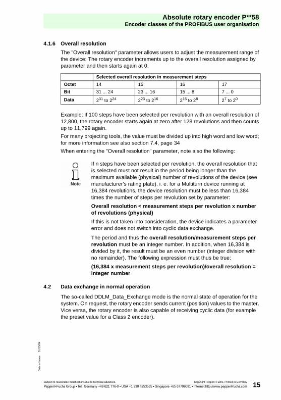
4.1.6 Overall resolution
The "Overall resolution" parameter allows users to adjust the measurement range of the device: The rotary encoder increments up to the overall resolution assigned by parameter and then starts again at 0.
Example: If 100 steps have been selected per revolution with an overall resolution of 12,800, the rotary encoder starts again at zero after 128 revolutions and then counts up to 11,799 again.
For many projecting tools, the value must be divided up into high word and low word; for more information see also section 7.4, page 34
When entering the "Overall resolution" parameter, note also the following:
4.2 Data exchange in normal operation
The so-called DDLM_Data_Exchange mode is the normal state of operation for the system. On request, the rotary encoder sends current (position) values to the master. Vice versa, the rotary encoder is also capable of receiving cyclic data (for example the preset value for a Class 2 encoder).
Selected overall resolution in measurement steps
Octet 14 15 16 17
Bit 31 ... 24 23 ... 16 15 ... 8 7 ... 0
Data 231 to 224 223 to 216 215 to 28 27 to 20
If n steps have been selected per revolution, the overall resolution that is selected must not result in the period being longer than the maximum available (physical) number of revolutions of the device (see manufacturer's rating plate), i. e. for a Multiturn device running at 16,384 revolutions, the device resolution must be less than 16,384 times the number of steps per revolution set by parameter:
Overall resolution < measurement steps per revolution x number of revolutions (physical)
If this is not taken into consideration, the device indicates a parameter error and does not switch into cyclic data exchange.
The period and thus the overall resolution/measurement steps per revolution must be an integer number. In addition, when 16,384 is divided by it, the result must be an even number (integer division with no remainder). The following expression must thus be true:
(16,384 x measurement steps per revolution)/overall resolution = integer number
Note

Absolute rotary encoder P**58Encoder classes of the PROFIBUS user organisation
Subject to reasonable modifications due to technical advances. Copyright Pepperl+Fuchs, Printed in Germany
Pepperl+Fuchs Group • Tel.: Germany +49 621 776-0 • USA +1 330 4253555 • Singapore +65 67799091 • Internet http://www.pepperl-fuchs.com
Dat
e of
issu
e01
/15/
04
16
4.2.1 Transferring the actual process value
In the case of a Multiturn encoder, the current position value is transferred to the master as a 32 bit value (double word):
Similarly, transfer for a Singleturn encoder is as a 16 bit value (word).
4.2.2 Preset function
The Preset function can be used to adjust the encoder zero point to the mechanical zero point of the system. Setting the preset value sets the actual value of the rotary encoder to the desired "Preset value". The necessary zero point offset is calculated by the device and stored zero-voltage-safe in an EEPROM (requires less than 40 ms).
The preset value is activated by Bit 31 in the (peripheral) output double word (accepted with a rising edge). The preset value must be set after the scaling parameters are transferred, i. e. the preset value refers to the actual scaled value.
(The procedure can be applied to the Singleturn version with appropriate changes – in this case, Bit 15 is used to activate the preset value.)
If very high precision is required, the preset value should only be set when the rotary encoder shaft is at rest. If the shaft moves very rapidly during this time, there may be shifts, since run times may occur through the bus while the preset value is being set.
Word word 1 word 0
Function status bits actual process value
Bit 31 30 29 28 27 26 25 24 23 22 21 20 19 18 17 16 15 14 13 12 11 10 9 8 7 6 5 4 3 2 1 0
0 0 0 0 0 0 0 X X X X X X X X X X X X X X X X X X X X X X X X X
Status bits Data bits
Bit 31 30 29 28 27 26 25 24 23 22 21 20 19 18 17 16 15 14 13 12 11 10 9 8 7 6 5 4 3 2 1 0
Master → Encoder 1 0 0 0 0 0 0 transfer of desired value (= Preset value)
Encoder → Master
0 0 0 0 0 0 0 new = desired actual process value is transferred
Master → Encoder
0 0 0 0 0 0 0reset Bit 31 – normal mode
Encoder → Master
0 0 0 0 0 0 0 new = desired actual process value is transferred

Absolute rotary encoder P**58Manufacturer specific encoder classes
Subject to reasonable modifications due to technical advances. Copyright Pepperl+Fuchs, Printed in Germany
Pepperl+Fuchs Group • Tel.: Germany +49 621 776-0 • USA +1 330 4253555 • Singapore +65 67799091 • Internet http://www.pepperl-fuchs.com
Dat
e of
issu
e01
/15/
04
17
5 Manufacturer specific encoder classes
With manufacturer specific encoder classes P+F 2.1 and P+F 2.2, the rotary encoder offers, in addition to functions based on the encoder profile of the PROFIBUS user organisation, functions such as commissioning mode (TEACH-IN), speed output and limit switches.
The following table describes transfer of individual parameters in the parameter assignment telegram. Note also the following: Users will generally be using user-friendly input masks in the projecting tool. The structure of the parameter assignment telegram itself is only of interest in exceptional cases.
Octet no. Parameter Bit no. Details
1 ... 8 PROFIBUS standard parameter
9 direction of rotation 0 section 4.1.1, page 13
Class 2 functionality 1 section 4.1.2, page 14
commissioning diagnostics 2 section 4.1.3, page 14
scaling function 3 section 4.1.4, page 14
reserved 4
reserved 5
activate manufacturer specific parameters (Octet 26) 6 section 5.1.1, page 18
reserved 7
10 ... 13desired measurement steps (reference: Octet 26 Bits 0 and 1) section 5.1.2, page 18
14 ... 17 overall resolution section 4.1.6, page 15
18 ... 25 reserved (according to encoder profile)
26reference for desired measurement steps
0section 5.1.3, page 19
1
activate commissioning mode 2 section 5.1.4, page 20
reduced diagnostics 3 section 5.1.5, page 20
reserved 4
activate lower software limit switch 5 section 5.1.6, page 20
activate upper software limit switch 6 section 5.1.6, page 20
activation of parameters starting at Octet 27 7 section 5.1.1, page 18
27 ... 30 lower limit switch section 5.1.6, page 20
31 ... 34 upper limit switch section 5.1.6, page 20
35 ... 38 physical measurement steps section 5.1.7, page 21
39 reserved 0
rotary encoder type (singleturn or multiturn) 1 section 5.1.8, page 22
reserved 2
reserved 3
selection of unit of measure for speed output4
section 5.1.9, page 225
reserved 6
reserved 7

Absolute rotary encoder P**58Manufacturer specific encoder classes
Subject to reasonable modifications due to technical advances. Copyright Pepperl+Fuchs, Printed in Germany
Pepperl+Fuchs Group • Tel.: Germany +49 621 776-0 • USA +1 330 4253555 • Singapore +65 67799091 • Internet http://www.pepperl-fuchs.com
Dat
e of
issu
e01
/15/
04
18
5.1 Parameters
Manufacturer specific parameters are described in greater detail below. For a description of parameters based on the encoder profile (that are also supported), see section 4.
5.1.1 Activation of manufacturer specific parameters
• The manufacturer specific parameter byte 26 is activated with Bit 6 in Octet 9.
• Manufacturer specific Octets 27 ... 39 are further activated in Octet 26.
If Encoder class P+F 2.1 or P+F 2.2 is selected, this happens automatically. These bits only need to be considered if parameters are assigned "manually" in hexadecimal.
5.1.2 Desired measurement steps
The parameter "Desired measurement steps" is used to program the device so that any number of measurement steps can be implemented in reference to one revolution, the entire measurement range or any given partial measurement range.
What the measurement steps refer to is specified with the parameter "Resolution reference" (see section 5.1.3). If "per revolution" is selected here as the reference for the desired measurement steps, the measurement range can be adjusted with the parameter "Overall resolution". The rules listed in section 4.1.6 must be taken into consideration for this.
Octet 9 Bit 6 Octet 26
0 deactivated
1 activated
Octet 26 Bit 7 Octet 27 ... 39
0 deactivated
1 activated
Desired measurement steps
Octet 10 11 12 13
Bit 31 ... 24 23 ... 16 15 ... 8 7 ... 0
Data 231 to 224 223 to 216 215 to 28 27 to 20
For many projecting tools, the value must be divided up into high word and low word; for more information see section 7.4, page 34.
Note

Absolute rotary encoder P**58Manufacturer specific encoder classes
Subject to reasonable modifications due to technical advances. Copyright Pepperl+Fuchs, Printed in Germany
Pepperl+Fuchs Group • Tel.: Germany +49 621 776-0 • USA +1 330 4253555 • Singapore +65 67799091 • Internet http://www.pepperl-fuchs.com
Dat
e of
issu
e01
/15/
04
19
5.1.3 Resolution reference
This parameter is used to specify what the "desired measurement steps" that are entered should refer to (see section 5.1.2):
• Revolution
• maximum overall resolution
• Physical measurement steps
Desired resolution per revolution
In this case the position value is set in such a manner that it is incremented by the number of desired measurement steps for each revolution. In addition, in this case the "Overall resolution" parameter is evaluated. It can be used to adjust the measurement range (see section 4.1.6).
Desired resolution per maximum overall resolution
The desired measurement steps that are entered refer to the entire measurement range of the device, i. e. the device generates the number of measurement steps assigned by parameter over the entire (physical) number of revolutions.
Desired resolution per physical measurement steps
In this case, the desired number of steps refers to the physical measurement steps entered with the "Physical measurement steps" parameter (see also section 5.1.7). In this context, physical steps means the numeric value that is read internally from the code disk by the rotary encoder (for example 4,096 steps per revolution for the standard 12 bit version). Gear factors can be freely set with this option.
Reference Octet 26 Bit 0 Octet 26 Bit 1
per revolution 0 0
per maximum overall resolution 1 0
per physical measurement steps (= steps specified in Octet 35 ... 38) 0 1

Absolute rotary encoder P**58Manufacturer specific encoder classes
Subject to reasonable modifications due to technical advances. Copyright Pepperl+Fuchs, Printed in Germany
Pepperl+Fuchs Group • Tel.: Germany +49 621 776-0 • USA +1 330 4253555 • Singapore +65 67799091 • Internet http://www.pepperl-fuchs.com
Dat
e of
issu
e01
/15/
04
20
5.1.4 Activate commissioning mode
Bit 2 in Octet 26 represents a switch for "commissioning mode". Commissioning mode is a special state of the device in which additional parameters beyond the Preset value can be transferred to the rotary encoder. When commissioning mode is activated, you can perform "TEACH-IN", a form of programming in which the gear factor can be determined by moving the system directly. In this mode (recognisable by the flashing green LED) the direction of rotation and scaling set during projecting are ignored. Instead of them, values stored internally in EEPROM are used.
The device can also be operated long term in commissioning mode. We recommend, however, that you transfer the parameters determined in commissioning mode to projecting and then use the device in normal mode. (This makes it possible to replace the device without having to perform TEACH-IN again).
For a detailed description of commissioning mode, please refer to section 5.3.
5.1.5 Reduced diagnostics
For many PROFIBUS masters, the full number of diagnostic bytes (standard diagnostics: 57 bytes) may lead to problems. Often older masters in particular cannot work with the full number of diagnostic bytes. With rotary encoders, there is the possibility of reducing the number of diagnostic bytes generated by the rotary encoder to 16. If "Class 1" is selected as the device class, only 16 diagnostic bytes will be generated.
5.1.6 Software limit switches
Two positions can be programmed. If the value falls above or below these limits respectively, the absolute encoder sets Bit 27 to "1" in the 32-bit actual process value. The bit is set to "0" between these two positions. Both limit switch values can be set as desired with parameter assignment, but they must not exceed the value of the "Overall resolution" parameter. Limit switches are activated via Bits 5 and 6 in Octet 26.
Octet 26 Bit 2 Commissioning mode
0 turned off
1 turned on
Octet 26 Bit 3 Diagnostic data length
0 standard = 57 bytes
1 reduced = 16 bytes
Octet 26 Bit 5 Lower limit switch
0 turned off
1 turned on
Octet 26 Bit 6 Upper limit switch
0 turned off
1 turned on

Absolute rotary encoder P**58Manufacturer specific encoder classes
Subject to reasonable modifications due to technical advances. Copyright Pepperl+Fuchs, Printed in Germany
Pepperl+Fuchs Group • Tel.: Germany +49 621 776-0 • USA +1 330 4253555 • Singapore +65 67799091 • Internet http://www.pepperl-fuchs.com
Dat
e of
issu
e01
/15/
04
21
For many projecting tools, values must be divided up into high word and low word; for more information see section 7.4, page 34
5.1.7 Physical measurement steps
This parameter is evaluated by the device if "Physical measurement steps" was selected as the reference for the desired measurement steps(see section 5.1.3).
A gear factor can be freely selected using "Physical measurement steps". The user specifies in this process how many measurement steps ("Desired measurement steps") should be generated for a specified partial measurement range. This option is helpful if you will be entering "uneven" scaling factors.
Lower limit switch in measurement steps (in reference to scaled value)
Octet 27 28 29 30
Bit 31 ... 24 23 ... 16 15 ... 8 7 ... 0
Data 231 to 224 223 to 216 215 to 28 27 to 20
Upper limit switch in measurement steps (in reference to scaled value)
Octet 31 32 33 34
Bit 31 ... 24 23 ... 16 15 ... 8 7 ... 0
Data 231 to 224 223 to 216 215 to 28 27 to 20
Physical measurement steps
Octet 35 36 37 38
Bit 31 ... 24 23 ... 16 15 ... 8 7 ... 0
Data 231 to 224 223 to 216 215 to 28 27 to 20

Absolute rotary encoder P**58Manufacturer specific encoder classes
Subject to reasonable modifications due to technical advances. Copyright Pepperl+Fuchs, Printed in Germany
Pepperl+Fuchs Group • Tel.: Germany +49 621 776-0 • USA +1 330 4253555 • Singapore +65 67799091 • Internet http://www.pepperl-fuchs.com
Dat
e of
issu
e01
/15/
04
22
Example:
Problem: The rotary encoder must generate 400 steps over 3 revolutions.
This number of steps cannot be set with the "Desired measurement steps per revolution" reference (the "Desired measurement steps" would have to contain the value 133,333 but only whole numbers can be entered in this case).
Solution:
"Physical measurement steps" is selected as a reference for the desired number of steps.
The number of physical measurement steps over the desired measurement range is determined based on the actual (physical) resolution of the device (see the manufacturer's rating plate). For an absolute encoder with a standard resolution of 12 bits, for example, this would be
4,096 steps/revolution x 3 revolutions = 12,288 steps in this case
This value is then entered as the "Physical measurement steps" parameter and the actual number of steps desired, 400, is entered under "Desired measurement steps". The rotary encoder now generates 400 steps for a measurement range of 12,288 physical steps (i. e. for 3 revolutions).
5.1.8 Rotary encoder type
The type of rotary encoder (singleturn or multiturn) is specified in Bit 1 of Octet 39. This happens automatically if the encoder class is selected. The user only needs to make note of this parameter if parameter assignment is made directly in hexadecimal.
5.1.9 Unit of measure for speed
You can use this parameter to adjust the unit for speed output (Class P+F 2.2). This base value will be stored in Bits 4 and 5 of Octet 39.
For many projecting tools, the value must be divided up into high word and low word; for more information see also section 7.4, page 34
Octet 39 Bit 1 Type
0 singleturn
1 multiturn
Unit Bit 4 Bit 5
steps/second 0 0
steps/100 ms 1 0
steps/10 ms 0 1
revolutions/minute 1 1
Note

Absolute rotary encoder P**58Manufacturer specific encoder classes
Subject to reasonable modifications due to technical advances. Copyright Pepperl+Fuchs, Printed in Germany
Pepperl+Fuchs Group • Tel.: Germany +49 621 776-0 • USA +1 330 4253555 • Singapore +65 67799091 • Internet http://www.pepperl-fuchs.com
Dat
e of
issu
e01
/15/
04
23
5.2 Data exchange in normal mode
For manufacturer specific encoder classes P+F 2.1 and P+F 2.2, the actual process value is transferred as a 32-bit value (double word). In addition to 25 bits that are used for the position value, another 7 bits are used as status bits. The master sends the Preset value to the rotary encoder along with the control bits in the (periphery) output double word.
The current speed value is transferred as well in an additional (periphery) input word in device class P+F 2.2:
The meanings of the status bits in the input double word are as follow:
Identifier F1 hex D0 hex
Enc. → Master status + actual position value speed
status + 224 223 ... 216 215 ... 28 27 ... 20 215 ... 28 27 ... 20
Master → Encoder Preset value + control bits
control + 224 223 ... 216 215 ... 28 27 ... 20
Bit 28 Bit 27 Bit 26 Bit 25 Meaning
ready for operation0 = rotary encoder not ready for operation1 = rotary encoder ready for operation
operating mode0 = commissioning mode1 = normal mode
software limit switch0 = lower limit switch = actual value = upper limit switch1 = actual value > upper limit switch or actual value < lower limit switch
direction of rotation0 = rising clockwise (as seen facing the shaft)1 = rising counterclockwise (as seen facing the shaft)

Absolute rotary encoder P**58Manufacturer specific encoder classes
Subject to reasonable modifications due to technical advances. Copyright Pepperl+Fuchs, Printed in Germany
Pepperl+Fuchs Group • Tel.: Germany +49 621 776-0 • USA +1 330 4253555 • Singapore +65 67799091 • Internet http://www.pepperl-fuchs.com
Dat
e of
issu
e01
/15/
04
24
5.3 Commissioning mode
If the rotary encoder is switched into commissioning mode using parameter assignment, gear factors can be determined directly on the system using a process called "TEACH-IN".
Commissioning mode is indicated by the rotary encoder by the flashing green LED in the connection hood and by Bit 26 in the input double word (set to 0).
In commissioning mode, parameters set in projecting mode (direction of rotation and scaling) are ignored. Instead of them, values stored internally in EEPROM are used. If the direction of rotation and gear factor are changed in commissioning mode, the new values are stored in EEPROM and the device will then use these new values.
The main procedure in commissioning mode is as follows:
• Install the device into the system.
• Turn on commissioning mode with parameter assignment (see section 5.1.4).
• If necessary, adjust the direction of rotation.
• Move the system to its initial position.
• Transfer the Start command for TEACH-IN to the rotary encoder.
• Move the system to its end position.
• Use the TEACH-IN stop command to transfer the desired number of steps to the rotary encoder.
• The preset value is set.
• Transfer the values determined in TEACH-IN to projecting (parameters).
• Commissioning mode is turned off in parameter assignment.
5.3.1 Setting the direction of rotation
The direction of rotation in which the output code rises can be changed online in commissioning mode. The current direction of rotation is displayed with Bit 28 in the input double word (0: rising/1: falling, clockwise). The direction of rotation can be changed with Bit 28 in the output double word.
The direction of rotation that is set is saved zero-voltage-safe in EEPROM.
Status bits Data bits
Bit 31 30 29 28 27 26 25 24 23 22 21 20 19 18 17 16 15 14 13 12 11 10 9 8 7 6 5 4 3 2 1 0
Master → Encoder
0 0 0 1 0 0 0 changeover of direction of rotation via Bit 28
Encoder → Master
0 0 0 0/1 0 0 1rotary encoder acknowledged in Bit 0 and Bit 28 with new direction of rotation
0/1
Master → Encoder
0 0 0 0 0 0 0 changeover is ended by resetting Bit 28
Encoder → Master
0 0 0 0/1 X 0 1output of actual process value with modified direction of rotation

Absolute rotary encoder P**58Manufacturer specific encoder classes
Subject to reasonable modifications due to technical advances. Copyright Pepperl+Fuchs, Printed in Germany
Pepperl+Fuchs Group • Tel.: Germany +49 621 776-0 • USA +1 330 4253555 • Singapore +65 67799091 • Internet http://www.pepperl-fuchs.com
Dat
e of
issu
e01
/15/
04
25
5.3.2 TEACH-IN start
After the system has been moved to the beginning of the measurement range, the TEACH-IN start command is transferred to the rotary encoder. The device will now start the measurement for determining the gear factor internally.
5.3.3 TEACH-IN stop
After the system is moved over the measurement range with the TEACH-IN stop command, the number of steps desired over the measurement path must be transferred. Care should be taken that the physical resolution is not exceeded. Positive and negative direction as well as the zero point having been exceeded are automatically taken into consideration. The measurement path that is traversed must not exceed 2,047 revolutions.
In response to the TEACH-IN stop command, the rotary encoder transfers the overall resolution calculated by the device. This value should be noted and accepted later for normal operation of the system in projecting/parameter assignment.
After this procedure, the device works with the new scaling factor that has just been determined. It is stored zero-voltage-safe in EEPROM.
Status bits Data bits
Bit 31 30 29 28 27 26 25 24 23 22 21 20 19 18 17 16 15 14 13 12 11 10 9 8 7 6 5 4 3 2 1 0
Master → Encoder 0 1 0 0 0 0 0 start of TEACH-IN by setting Bit 30
Encoder → Master
0 1 0 X X 0 1 rotary encoder acknowledges start of TEACH-IN by setting Bit 30
Master → Encoder 0 0 0 0 0 0 0 reset Bit 30
Encoder → Master 0 1 0 X X 0 1 output of uncalculated feedback value (gear factor = 1,
Preset not active)
The gear factor is set to 1 internally; the zero point offset is deleted.
Status bits Data bits
Bit 31 30 29 28 27 26 25 24 23 22 21 20 19 18 17 16 15 14 13 12 11 10 9 8 7 6 5 4 3 2 1 0
Master → Encoder 0 0 1 0 0 0 0 number of desired steps via measurement path traversed
Encoder → Master 0 1 1 X X 0 1 determination of overall resolution for new gear factor (should
be noted for later reference)
Master → Encoder
0 0 0 0 0 0 0 reset Bit 29
Encoder → Master 0 0 0 X X 0 1 output of actual value calculated with the new gear factor
Note

Absolute rotary encoder P**58Manufacturer specific encoder classes
Subject to reasonable modifications due to technical advances. Copyright Pepperl+Fuchs, Printed in Germany
Pepperl+Fuchs Group • Tel.: Germany +49 621 776-0 • USA +1 330 4253555 • Singapore +65 67799091 • Internet http://www.pepperl-fuchs.com
Dat
e of
issu
e01
/15/
04
26
To make it possible to replace the encoder later without having to repeat the TEACH-IN procedure, the overall resolution determined by the encoder should be transferred to projecting. This is done by entering the overall resolution that was determined du-ring TEACH-IN (and noted for future reference) in the parameter field "Desired mea-surement steps" (see section 5.1.2) and then setting the "Resolution reference" switch to "Maximum overall resolution" (see section 5.1.3). Care must be taken in the reconfiguration that the direction of rotation (see section 4.1.1) is entered correctly. The setting in commissioning mode must also be observed when assigning parame-ters. Then commissioning mode can be turned off with parameter assignment. The rotary encoder is now used in "normal mode".
5.3.4 Preset value
The preset value can be set in a manner similar to the procedure described in section 4.2.2. The only difference is that setting of the preset value is confirmed for manufacturer specific classes P+F 2.1 and P+F 2.2 by a status bit:
Status bits Data bits
Bit 31 30 29 28 27 26 25 24 23 22 21 20 19 18 17 16 15 14 13 12 11 10 9 8 7 6 5 4 3 2 1 0
Master → Encoder
1 0 0 0 0 0 0 transfer of desired value (= Preset value)
Encoder → Master 1 0 0 0 0 0 1 new = desired actual process value is transferred
Master → Encoder 0 0 0 0 0 0 0 reset Bit 31 – normal mode
Encoder → Master
0 0 0 0 0 0 1 new = desired actual process value is transferred

Absolute rotary encoder P**58Diagnostic messages
Subject to reasonable modifications due to technical advances. Copyright Pepperl+Fuchs, Printed in Germany
Pepperl+Fuchs Group • Tel.: Germany +49 621 776-0 • USA +1 330 4253555 • Singapore +65 67799091 • Internet http://www.pepperl-fuchs.com
Dat
e of
issu
e01
/15/
04
27
6 Diagnostic messages
6.1 Overview
In the "DDLM_Slave_Diag" operating mode, diagnostic data is transferred from the rotary encoder to the master on request. The number of diagnostic bytes is 57. Exception: Reduced diagnostics (see section 5.1.5). Output of diagnostic data is based on the specifications of the PROFIBUS standard (Octets 1 ... 6) or on the encoder profile (starting at Octet 7).
Diagnostic function Data typeDiagnostic Octet number
Encoder class
Station status 1 (see: PROFIBUS standard) Octet 1 1
Station status 2 (see: PROFIBUS standard) Octet 2 1
Station status 3 (see: PROFIBUS standard) Octet 3 1
Diagnostic master address Octet 4 1
Profibus user organisation ID number Octet 5, 6 1
Advanced diagnostics header Octet string 7 1
Alarm messages Octet string 8 1
Operating status Octet string 9 1
Encoder type Octet string 10 1
Resolution per revolution (hardware) unsigned 32 11 ... 14 1
Number of revolutions (hardware) unsigned 16 15, 16 1
Additional alarm messages Octet string 17 2
Supported alarm messages Octet string 18, 19 2
Warning messages Octet string 20, 21 2
Supported warning messages Octet string 22, 23 2
Profile version Octet string 24, 25 2
Software version Octet string 26, 27 2
Operating time unsigned 32 28 ... 31 2
Reference point shift unsigned 32 32 ... 35 2
Manufacturer specific: offset values unsigned 32 36 ... 39 2
Resolution per revolution as assigned by parameter
unsigned 32 40 ... 43 2
Overall resolution as assigned by parameter unsigned 32 44 ... 47 2
Serial number ASCII string 48 ... 57 2

Absolute rotary encoder P**58Diagnostic messages
Subject to reasonable modifications due to technical advances. Copyright Pepperl+Fuchs, Printed in Germany
Pepperl+Fuchs Group • Tel.: Germany +49 621 776-0 • USA +1 330 4253555 • Singapore +65 67799091 • Internet http://www.pepperl-fuchs.com
Dat
e of
issu
e01
/15/
04
28
6.2 Supported diagnostic messages
Individual diagnostic entries are explained below in greater detail.
6.2.1 Advanced diagnostics header
Diagnostic Octet 7 contains the length of advanced diagnostics (including the diagnostics header itself).
6.2.2 Memory error
Bit 4 in diagnostic Octet 8 indicates whether a memory error has occurred.
In this context, a memory error means that the EEPROM of the rotary encoder is no longer functioning properly and zero-voltage-safe storage (for example of the zero point offset) is no longer ensured.
6.2.3 Operating status
Diagnostic Octet 9 can be used to query operating parameters that are set by parameter assignment.
6.2.4 Rotary encoder type
Diagnostic Octet 10 can be used to query the version of the rotary encoder.
6.2.5 Singleturn resolution
Diagnostic Octets 11 ... 14 can be used to store the physical resolution per revolution of the rotary encoder.
6.2.6 Number of revolutions
Diagnostic Octets 15 and 16 can be used to query the physical number of distinguishable revolutions. Standard values are 1 for Singleturn and 4,096 for Multiturn.
6.2.7 Operating time warning
Bit 4 of diagnostic Octet 20 displays the warning message for exceeding the operating time. The bit is set after 105 hours.
Bit Definition 0 1
4 memory error (defect in EEPROM) no yes
Bit Definition 0 1
0 direction of rotation cw ccw
1 Class 2 functionality off on
2 diagnostic routine off on
3 scaling function off on
Octet 10 Definition
0 singleturn rotary encoder
1 multiturn rotary encoder

Absolute rotary encoder P**58Diagnostic messages
Subject to reasonable modifications due to technical advances. Copyright Pepperl+Fuchs, Printed in Germany
Pepperl+Fuchs Group • Tel.: Germany +49 621 776-0 • USA +1 330 4253555 • Singapore +65 67799091 • Internet http://www.pepperl-fuchs.com
Dat
e of
issu
e01
/15/
04
29
6.2.8 Profile version
The profile version of the rotary encoder is stored in diagnostic Octets 24 and 25:
6.2.9 Software version
The software version of the rotary encoder is stored in diagnostic Octets 26 and 27.
6.2.10 Operating time
Diagnostic Octets 28 ... 31 contain the operating time of the device. When power supply voltage is applied, the "Operating time" value is stored again once every 6 minutes in the rotation encoder in increments of 0.1 hours.
6.2.11 Reference point shift
The zero point offset is available for output in diagnostic Octets 32 ... 35.
6.2.12 Resolution as assigned by parameter
Diagnostic Octets 40 ... 43 store the resolution per revolution as assigned by parameter. This value is only valid if the gear factor has been calculated with the setting "Resolution per revolution" in the parameter mask (see section 5.1.3).
6.2.13 Overall resolution as assigned by parameter
The overall resolution assigned by parameter or calculated is stored in diagnosticOctets 44 ... 47.
6.2.14 Serial number
Diagnostic Octets 48 ... 57 are provided for a serial number according to the encoder profile.
Revision no. Index
Octet 24 25
Bit 15 ... 8 7 ... 0
Data 27 ... 20 27 ... 20
Revision no. Index
Octet 26 27
Bit 15 ... 8 7 ... 0
Data 27 ... 20 27 ... 20

Absolute rotary encoder P**58Diagnostic messages
Subject to reasonable modifications due to technical advances. Copyright Pepperl+Fuchs, Printed in Germany
Pepperl+Fuchs Group • Tel.: Germany +49 621 776-0 • USA +1 330 4253555 • Singapore +65 67799091 • Internet http://www.pepperl-fuchs.com
Dat
e of
issu
e01
/15/
04
30
6.3 Status information of LEDs
The connection hood is equipped with two LEDs that provide a visual indication of the operating status on the rotary encoder. The red LED serves to display errors, while the green LED displays the status of the rotary encoder. Each LED can be in one of three states: On, Off, or Flashing. Of the nine possible combinations of these states, only seven are used to indicate a special status.
If problems occur while the device is being placed in service, the status of the LEDs should first be checked. Often this makes it possible to draw conclusions regarding the cause of the error.
No. red LED green LED Status information/possible cause
1 off off no power supply
2 on on
rotary encoder is ready for operation, but has not yet received any configuration data based on voltage;possible causes: address set incorrectly, bus line incorrectly connected
3 on flashing
error in parameter assignment or configurationthe rotary encoder is receiving configuration or parameter assignment data of incorrect length or inconsistent data;possible cause: (for example) overall resolution set to high
4 flashing onrotary encoder is ready for operation, but is not being accessed by the master (for example the wrong address may be accessed)
5 on off rotary encoder has not received any data for some time (approx. 40 seconds) (the data line may be interrupted)
6 off on normal operation in Data Exchange mode
7 off flashing commissioning mode in Data Exchange mode
Status displayLED green
Error displayLED red

Absolute rotary encoder P**58Sample configuration
Subject to reasonable modifications due to technical advances. Copyright Pepperl+Fuchs, Printed in Germany
Pepperl+Fuchs Group • Tel.: Germany +49 621 776-0 • USA +1 330 4253555 • Singapore +65 67799091 • Internet http://www.pepperl-fuchs.com
Dat
e of
issu
e01
/15/
04
31
7 Sample configuration
Commissioning of the rotary encoder is described below, using the STEP7 projecting tool (V5.1) and the CPU 315-2DP (with an integrated PROFIBUS interface) as examples. For questions related to other projecting tools, please contact the manufacturer in question.
7.1 Reading the GSD file
The first time it is used, the GSD file must be installed ("PFDG5046.gsd") to accept the rotary encoder in the hardware catalogue. Select "Install new GSD" in the "HW Config" window and select the GSD file ("PFDG5046.gsd").
After the GSD file is read, the rotary encoder appears in the hardware catalogue under "PROFIBUS-DP" – "Other field devices" – "Encoders" –"Rotary encoders".

Absolute rotary encoder P**58Sample configuration
Subject to reasonable modifications due to technical advances. Copyright Pepperl+Fuchs, Printed in Germany
Pepperl+Fuchs Group • Tel.: Germany +49 621 776-0 • USA +1 330 4253555 • Singapore +65 67799091 • Internet http://www.pepperl-fuchs.com
Dat
e of
issu
e01
/15/
04
32
7.2 Projecting the rotary encoder
After the PROFIBUS network has been configured in the hardware configurator using the menu item "Insert" – "Master system" the absolute encoder can be selected from the hardware catalogue and inserted into the network. To do this, connect the "Encoder" device to the bus using Drag and Drop (or double click on the module with the bus marked).
After the device has been inserted, the station address of the slave device must be entered. It must agree with the address set in the connection hood.

Absolute rotary encoder P**58Sample configuration
Subject to reasonable modifications due to technical advances. Copyright Pepperl+Fuchs, Printed in Germany
Pepperl+Fuchs Group • Tel.: Germany +49 621 776-0 • USA +1 330 4253555 • Singapore +65 67799091 • Internet http://www.pepperl-fuchs.com
Dat
e of
issu
e01
/15/
04
33
7.3 Selecting the device class
As described in section 3, the functionality of the device depends on which encoder class is selected. After the device has been inserted into the PROFIBUS network as described above, the desired device class can then be selected. To do this, drag one of the modules listed in the hardware catalogue under "Rotary encoders" to mounting station 1 using Drag and Drop (Table in the lower part of the station window):

Absolute rotary encoder P**58Sample configuration
Subject to reasonable modifications due to technical advances. Copyright Pepperl+Fuchs, Printed in Germany
Pepperl+Fuchs Group • Tel.: Germany +49 621 776-0 • USA +1 330 4253555 • Singapore +65 67799091 • Internet http://www.pepperl-fuchs.com
Dat
e of
issu
e01
/15/
04
34
7.4 Parameter assignment
Mark the rotary encoder to which you want to assign parameters in projecting and then double click on mounting station 1 (table in the lower part of the station window). The "DP slave properties" dialog window appears. You can change the default address of the device here if you want to.
To enter parameters, select the "Parameter assignment" properties tab.
Next, enter the parameters of the device. After selecting the "Device-specific parameters" folder, various parameters can be entered, depending on the encoder class that is selected. If there is a selection between multiple options in the fields on the right, an additional selection window appears when you double click. On the other hand, numeric values can be entered directly. The example shows parameter selection for version P+F 2.2 – the device class with the greatest functionality.

Absolute rotary encoder P**58Sample configuration
Subject to reasonable modifications due to technical advances. Copyright Pepperl+Fuchs, Printed in Germany
Pepperl+Fuchs Group • Tel.: Germany +49 621 776-0 • USA +1 330 4253555 • Singapore +65 67799091 • Internet http://www.pepperl-fuchs.com
Dat
e of
issu
e01
/15/
04
35
As required by the STEP 7 projecting software, 32-bit parameter values (for example overall resolution, limit switches, etc.) are divided into high word and low word.
Example:
The decimal value "1" is entered in the high field, while the decimal value "64,064" is entered in the low field.
or:
Divide the value by 65,536 and enter the integer portion of the result into the high word, the remainder portion into the low word:
It is also possible to enter parameters directly as hex values. However, this is significantly more complicated. If possible, it should be avoided.
Decimal Hexadecimal Hexadecimal Decimal (input)
129,600 00 01 FA 40 high word 0001 1
low word FA 40 64,064
129,600/65,536 = 1,977539 → integer portion = 1 → high word:1
129,600 – 1 x 65,536 = 64,064 → remainder = 64,064 → low word = 64,064
Absolute rotary encoder P**58Technical data
Subject to reasonable modifications due to technical advances. Copyright Pepperl+Fuchs, Printed in Germany
Pepperl+Fuchs Group • Tel.: Germany +49 621 776-0 • USA +1 330 4253555 • Singapore +65 67799091 • Internet http://www.pepperl-fuchs.com
Dat
e of
issu
e01
/15/
04
36
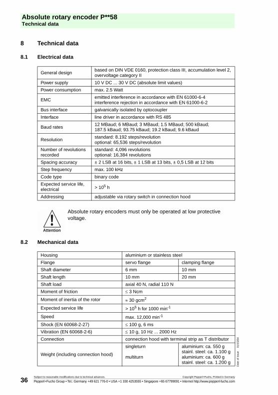
8 Technical data
8.1 Electrical data
8.2 Mechanical data
General designbased on DIN VDE 0160, protection class III, accumulation level 2, overvoltage category II
Power supply 10 V DC ... 30 V DC (absolute limit values)
Power consumption max. 2.5 Watt
EMC emitted interference in accordance with EN 61000-6-4interference rejection in accordance with EN 61000-6-2
Bus interface galvanically isolated by optocoupler
Interface line driver in accordance with RS 485
Baud rates 12 MBaud; 6 MBaud; 3 MBaud; 1.5 MBaud; 500 kBaud; 187.5 kBaud; 93.75 kBaud; 19.2 kBaud; 9.6 kBaud
Resolution standard: 8.192 steps/revolution optional: 65,536 steps/revolution
Number of revolutionsrecorded
standard: 4,096 revolutionsoptional: 16,384 revolutions
Spacing accuracy ± 2 LSB at 16 bits, ± 1 LSB at 13 bits, ± 0,5 LSB at 12 bits
Step frequency max. 100 kHz
Code type binary code
Expected service life, electrical > 105 h
Addressing adjustable via rotary switch in connection hood
Absolute rotary encoders must only be operated at low protective voltage.
Housing aluminium or stainless steel
Flange servo flange clamping flange
Shaft diameter 6 mm 10 mm
Shaft length 10 mm 20 mm
Shaft load axial 40 N, radial 110 N
Moment of friction ≤ 3 Ncm
Moment of inertia of the rotor ≈ 30 gcm2
Expected service life > 105 h for 1000 min-1
Speed max. 12,000 min-1
Shock (EN 60068-2-27) ≤ 100 g, 6 ms
Vibration (EN 60068-2-6) ≤ 10 g, 10 Hz ... 2000 Hz
Connection connection hood with terminal strip as T distributor
Weight (including connection hood)
singleturn
multiturn
aluminium: ca. 550 gstainl. steel: ca. 1.100 galuminium: ca. 600 gstainl. steel: ca. 1.200 g
Attention

Absolute rotary encoder P**58Technical data
Subject to reasonable modifications due to technical advances. Copyright Pepperl+Fuchs, Printed in Germany
Pepperl+Fuchs Group • Tel.: Germany +49 621 776-0 • USA +1 330 4253555 • Singapore +65 67799091 • Internet http://www.pepperl-fuchs.com
Dat
e of
issu
e01
/15/
04
37
8.3 Ambient conditions
Working temperature range -40 °C ... +85 °C
Storage temperature range -40 °C ... +85 °C
Relative humidity 98 % (no moisture condensation)
Protection class (EN 60529)
Housing side IP65
Shaft side IP64 (without shaft seal)IP66 (with shaft seal)

Absolute rotary encoder P**58Technical data
Subject to reasonable modifications due to technical advances. Copyright Pepperl+Fuchs, Printed in Germany
Pepperl+Fuchs Group • Tel.: Germany +49 621 776-0 • USA +1 330 4253555 • Singapore +65 67799091 • Internet http://www.pepperl-fuchs.com
Dat
e of
issu
e01
/15/
04
38
8.4 Dimensional drawings
8.4.1 Rotary encoder with servo flange
Singleturn design
Multiturn design
3 x M4
6 deep
Servo flange
Cable gland PG9, radial
10
3 x 120˚
23
30
~32
ø59
4
82
ø58
ø50
f7ø
6f6
3 3
ø60
ø42
63.5
15
ø5.5 ... ø9 20 20
3 x M4
6 deep
Servo flange
Cable gland PG9, radial
10
3 x 120˚
23
30
~32
ø59
4
92
ø58
ø50
f7ø
6f6
3 3
ø60
ø42
63.5
15
ø5.5 ... ø9 20 20

Absolute rotary encoder P**58Technical data
Subject to reasonable modifications due to technical advances. Copyright Pepperl+Fuchs, Printed in Germany
Pepperl+Fuchs Group • Tel.: Germany +49 621 776-0 • USA +1 330 4253555 • Singapore +65 67799091 • Internet http://www.pepperl-fuchs.com
Dat
e of
issu
e01
/15/
04
39
8.4.2 Rotary encoder with clamp flange
Singleturn design
Multiturn design
Cable gland PG9, radial
Clamping flange
3 x M4
6 deep
3 x M3
6 deep
23
30
~32
ø59
10
30 82ø
58
ø53
ø36
f7
1
ø10
h8
3 3
ø60 ø48
18
63.5
15
ø5.5 ... ø9 20 20
3 x 120˚
15˚
Cable gland PG9, radial
Clamping flange
3 x M4
6 deep
3 x M3
6 deep
23
30
~32
ø59
10
30 92
ø58
ø53
ø36
f7
1
ø10
h8
3 3
ø60 ø48
18
63.5
15
ø5.5 ... ø9 20 20
3 x 120˚
15˚

Absolute rotary encoder P**58Technical data
Subject to reasonable modifications due to technical advances. Copyright Pepperl+Fuchs, Printed in Germany
Pepperl+Fuchs Group • Tel.: Germany +49 621 776-0 • USA +1 330 4253555 • Singapore +65 67799091 • Internet http://www.pepperl-fuchs.com
Dat
e of
issu
e01
/15/
04
40
8.4.3 Rotary encoder with recessed hollow shaft
Singleturn design
Multiturn design
Cable gland PG9, radial
max. insertiondepth = 30min. insertiondepth = 15La
y-on
edg
e to
rque
res
t
* shaft can be reduced to ø10F7 or ø12F7 by using an adapter
Recessed hollow shaft
3.3
1.3
3.2
63.5
15
ø5.5 ... ø9
72
ø63
20 20˚
ø59
23
100
30
20 20
~32
ø60
ø15
F7*
Cable gland PG9, radial
max. insertiondepth = 30min. insertiondepth = 15La
y-on
edg
e to
rque
res
t
* shaft can be reduced to ø10F7 or ø12F7 by using an adapter
Recessed hollow shaft
3.3
1.3
3.2
63.5
15
ø5.5 ... ø9
72
ø63
20 20˚
ø59
23
112
30
20 20
~32
ø60
ø15
F7*

Absolute rotary encoder P**58Appendix
Subject to reasonable modifications due to technical advances. Copyright Pepperl+Fuchs, Printed in Germany
Pepperl+Fuchs Group • Tel.: Germany +49 621 776-0 • USA +1 330 4253555 • Singapore +65 67799091 • Internet http://www.pepperl-fuchs.com
Dat
e of
issu
e01
/15/
04
41
9 Appendix
9.1 Type code, model number
P 5 8 – A G R 0 B N – 1 2 1 3
Number of bits singleturn13 8,192 (standard)16 65,536
Number of bits multiturn12 4,096 (standard)14 16,384
Option 2N not extended
Output codeB binary
Option 10 no option
Exit positionR radial
Connection typeAG removable housing cover with terminal compartment
Shaft dimension/flange version011 shaft Ø10 mm x 20 mm with clamp flange032 shaft Ø6 mm x 10 mm with servo flangeF1A recessed hollow shaft Ø10 mm x 30 mmF2A recessed hollow shaft Ø12 mm x 30 mm
Housing materialN Aluminium, powder-coatedI Inox
Principle of operationM multiturnS singleturn
Shaft versionS recessed hollow shaftV solid shaft
Data formatP PROFIBUS

Absolute rotary encoder P**58Appendix
Subject to reasonable modifications due to technical advances. Copyright Pepperl+Fuchs, Printed in Germany
Pepperl+Fuchs Group • Tel.: Germany +49 621 776-0 • USA +1 330 4253555 • Singapore +65 67799091 • Internet http://www.pepperl-fuchs.com
Dat
e of
issu
e01
/15/
04
42
9.2 Troubleshooting
Problem
If one of the following PROFIBUS masters is used, problems occur when the system starts up if encoder classes higher than Class 1 are used (bus malfunction, encoder does not report):
• SIEMENS S5-95U
• Master connection SIEMENS IM 308-B
• Softing PROFIboard
• Allen Bradley 1785 PFB/B
• Mitsubishi A1SJ 71PB92D
Possible cause
Masters do not support the full number of diagnostic bytes (57 bytes) made available by absolute encoders in some circumstances.
Solution
If this is a possibility, the maximum amount of diagnostic data per slave should be increased in the master.
If this is not a possibility, the absolute encoder can either be used as a Class1 device (16 diagnostic bytes), or one of the manufacturer specific P+F classes can be selected (P+F 2.1 or 2.2), in which case "Reduced diagnostics" should be turned on in parameter assignment (see section 5.1.5).
Problem:
For COM PROFIBUS version 5.0, the P+F absolute encoder cannot be projected together with the S5-95U.
Cause
The S5-95U does not support the full amount of diagnostic data (57 bytes).
For the COM PROFIBUS version 5.0, the GSD entry "Max_Diag_Data_Len=57" is checked and projecting together with the S5-95U is prevented.
Solution
Use COM PROFIBUS version 3.3, select one of the manufacturer specific P+F classes (P+F 2.1 or 2.2), and activate reduced diagnostics (parameter).
Use with COM Profibus Version 5.0 is only possible with a modified GSD file (the slave key "Max_Diag_Data_Len" must be changed).For COM PROFIBUS version 5.0, the P+F absolute encoder cannot be projected together with the S5-95U.

Absolute rotary encoder P**58Appendix
Subject to reasonable modifications due to technical advances. Copyright Pepperl+Fuchs, Printed in Germany
Pepperl+Fuchs Group • Tel.: Germany +49 621 776-0 • USA +1 330 4253555 • Singapore +65 67799091 • Internet http://www.pepperl-fuchs.com
Dat
e of
issu
e01
/15/
04
43
Problem
The PLC and master connection are turned on and the bus is active, but the absolute encoder is not reporting.
Solution
First, check the status of the LEDs in the connection hood (see section 6.3). In some cases this will allow you to draw conclusions to determine what the cause of the error is.
• Both LEDs off: Check the power supply!
• Both LEDs on: The device is not receiving any parameters or configuration data. Check the address setting in the connection hood. Check for correction connection of bus lines (BUS IN/BUS OUT). Check projecting.
• Red LED on, green LED flashing: Parameter error! Check parameter assignment: (for example the overall resolution (see section 4.1.6)
Problem
Bus malfunctions occur sporadically.
Possible cause
Terminating resistors not correct
Solution
Check terminating resistors!
A terminating resistor of 220 Ω must be switched into the circuit at the beginning and end of the bus segment. Measure the resistance between the two data lines! To do this, turn off the power supply and measure in the connection hood between connections "A" and "B". The measured resistance value must be approximately 110 Ω (parallel 220 Ω).
Problem
Bus malfunctions occur sporadically.
Possible cause
EMC problems
Solution
Check whether the baud rate that is set is permissible for the line length. It may be necessary to use a lower baud rate. Check the connection hood to ensure the shield is connected properly and that the cable is laid properly for EMC.

Absolute rotary encoder P**58Appendix
Subject to reasonable modifications due to technical advances. Copyright Pepperl+Fuchs, Printed in Germany
Pepperl+Fuchs Group • Tel.: Germany +49 621 776-0 • USA +1 330 4253555 • Singapore +65 67799091 • Internet http://www.pepperl-fuchs.com
Dat
e of
issu
e01
/15/
04
44
9.3 Terms
Term Meaning
Address A number that is assigned to each bus station regardless of whether it is a master or slave. For a rotary encoder, it can be adjusted in the connection hood with decimal rotary switches and is retained in memory even when the power is turned off.
Baud rate The speed of a data transfer; indicates then number of bits transferred per second (baud rate = bit rate).
Bus station A device that is capable of sending, receiving or amplifying data via the bus.
Configuration During configuration, the master specifies properties of the slave, for example the number of input and output words. (→ DDLM_Set_Prm).
DDLM Direct Data Link Mapper. The interface between PROFIBUS DP functions and the encoder software.
DDLM_Data_Exchange The operating status of the bus in which "normal" data traffic occurs.
DDLM_Set_Prm The operating status of the bus in which configuration data is transferred.
DDLM_Slave_Diag The operating status of the bus in which diagnostic data is requested by the slave (for example rotary encoder).
Diagnostics Detection, pinpointing, classification, display and further evaluation of faults, malfunctions and messages.
DP Local peripherals
Encoder Alternative designation for absolute rotary encoder
Freeze A master command to the slave. The master is thus able to freeze the states of the inputs to the current value. Input data is not updated again until after the UNFREEZE command is sent.
GSD file Device master data file (in german: Geräte-Stammdaten-Datei). A file in which slave-specific properties are specified. The GSD is a file that is made available by the manufacturer for most PROFIBUS stations. The formats of the GSD are specified in a uniform manner, thus facilitating access to them by the corresponding control software. (→ type file).
Master A bus station that is able to send data "of its own initiative". It also determines which slave should send data at any given time. (→ Slave)
Octet, Byte A data unit of 8 bits = 1 byte
Parameter assignment Transfer of specific parameters (in this case, for example resolution per revolution, direction of rotation, etc.) from the master to the slave (in this case the rotary encoder). Parameter assignment is performed when the system starts up.
PROFIBUS Process Fieldbus, a european fieldbus standard specified in the PROFIBUS standard. It assigns functional electrical and mechanical properties to a bit-serial fieldbus system.

Absolute rotary encoder P**58Appendix
Subject to reasonable modifications due to technical advances. Copyright Pepperl+Fuchs, Printed in Germany
Pepperl+Fuchs Group • Tel.: Germany +49 621 776-0 • USA +1 330 4253555 • Singapore +65 67799091 • Internet http://www.pepperl-fuchs.com
Dat
e of
issu
e01
/15/
04
45
Rotary encoders Alternative designation for absolute rotary encoder
Slave A bus station that essentially sends data only in response to the command of a → master. Rotary encoders are always slaves by definition.
Terminating resistor Resistance to line adjustment with bus cable; terminating resistors; always required at cable and segment ends.
Type file Similar to a GSD file; used by older projecting tools.
Word Frequently, but not uniformly used for a data unit of 2 bytes.
Term Meaning

Absolute rotary encoder P**58Index
Subject to reasonable modifications due to technical advances. Copyright Pepperl+Fuchs, Printed in Germany
Pepperl+Fuchs Group • Tel.: Germany +49 621 776-0 • USA +1 330 4253555 • Singapore +65 67799091 • Internet http://www.pepperl-fuchs.com
Dat
e of
issu
e01
/15/
04
46
10 Index
C
ccw. . . . . . . . . . . . . . . . . . . . . . . . . . . . . . . . . . . . . . . . . . . . . . . . . . . . . . . . . . . . . . 13
Clamping flange . . . . . . . . . . . . . . . . . . . . . . . . . . . . . . . . . . . . . . . . . . . . . . . . . . . . 39
Code type. . . . . . . . . . . . . . . . . . . . . . . . . . . . . . . . . . . . . . . . . . . . . . . . . . . . . . . . . 36
Commissioning mode . . . . . . . . . . . . . . . . . . . . . . . . . . . . . . . . . . . . . . . . . . . . . . . 24
Configuration (identifier). . . . . . . . . . . . . . . . . . . . . . . . . . . . . . . . . . . . . . . . . . . . . . 12
Counting direction . . . . . . . . . . . . . . . . . . . . . . . . . . . . . . . . . . . . . . . . . . . . . . . . . 13
cw. . . . . . . . . . . . . . . . . . . . . . . . . . . . . . . . . . . . . . . . . . . . . . . . . . . . . . . . . . . . . . . 13
D
DDLM_Data_Exchange . . . . . . . . . . . . . . . . . . . . . . . . . . . . . . . . . . . . . . . .10, 15, 44
Desired measurement steps . . . . . . . . . . . . . . . . . . . . . . . . . . . . . . . . . . . . . . . . . . 18
Device address . . . . . . . . . . . . . . . . . . . . . . . . . . . . . . . . . . . . . . . . . . . . . . . . . . . . .6
Diagnostic bytes. . . . . . . . . . . . . . . . . . . . . . . . . . . . . . . . . . . . . . . . . . . . . . . . . . . . 20
Direction of rotation . . . . . . . . . . . . . . . . . . . . . . . . . . . . . . . . . . . . . . . . . . . . . . 13, 24
I
EEPROM . . . . . . . . . . . . . . . . . . . . . . . . . . . . . . . . . . . . . . . . . . . . . . . . . . . . . . . . . 20
Encoder class . . . . . . . . . . . . . . . . . . . . . . . . . . . . . . . . . . . . . . . . . . . . . . . . . . . . .33
Encoder classes. . . . . . . . . . . . . . . . . . . . . . . . . . . . . . . . . . . . . . . . . . . . . .10, 11, 17
Encoder is not reporting. . . . . . . . . . . . . . . . . . . . . . . . . . . . . . . . . . . . . . . . . . . . . . 43
G
Gear factor . . . . . . . . . . . . . . . . . . . . . . . . . . . . . . . . . . . . . . . . . . . . . . . . . . . . . . . . 20
GSD file . . . . . . . . . . . . . . . . . . . . . . . . . . . . . . . . . . . . . . . . . . . . . . . . . . . . . . . 10, 44
H
High word. . . . . . . . . . . . . . . . . . . . . . . . . . . . . . . . . . . . . . . . . . . . . . . . . . . . . . . . . 35
Hollow shaft . . . . . . . . . . . . . . . . . . . . . . . . . . . . . . . . . . . . . . . . . . . . . . . . . . . . . . . 40
I
Installation of GSD file . . . . . . . . . . . . . . . . . . . . . . . . . . . . . . . . . . . . . . . . . . . . . . . 31
L
LED . . . . . . . . . . . . . . . . . . . . . . . . . . . . . . . . . . . . . . . . . . . . . . . . . . . . . . . . . . . . 30
Limit switch . . . . . . . . . . . . . . . . . . . . . . . . . . . . . . . . . . . . . . . . . . . . . . . . . . . . . . . 20
Low word . . . . . . . . . . . . . . . . . . . . . . . . . . . . . . . . . . . . . . . . . . . . . . . . . . . . . . . . . 35
M
Measurement range. . . . . . . . . . . . . . . . . . . . . . . . . . . . . . . . . . . . . . . . . . . . . . . . . 15
O
Overall resolution . . . . . . . . . . . . . . . . . . . . . . . . . . . . . . . . . . . . . . . . . . . . . . . . . . . 15

Absolute rotary encoder P**58Index
Subject to reasonable modifications due to technical advances. Copyright Pepperl+Fuchs, Printed in Germany
Pepperl+Fuchs Group • Tel.: Germany +49 621 776-0 • USA +1 330 4253555 • Singapore +65 67799091 • Internet http://www.pepperl-fuchs.com
Dat
e of
issu
e01
/15/
04
47
P
Physical measurement steps . . . . . . . . . . . . . . . . . . . . . . . . . . . . . . . . . . . 17, 19, 21
Power consumption . . . . . . . . . . . . . . . . . . . . . . . . . . . . . . . . . . . . . . . . . . . . . . . . 36
Power supply . . . . . . . . . . . . . . . . . . . . . . . . . . . . . . . . . . . . . . . . . . . . . . . . . . . . . 36
Preset function . . . . . . . . . . . . . . . . . . . . . . . . . . . . . . . . . . . . . . . . . . . . . . . . . 11, 16
Preset set . . . . . . . . . . . . . . . . . . . . . . . . . . . . . . . . . . . . . . . . . . . . . . . . . . . . . 16, 26
Preset value . . . . . . . . . . . . . . . . . . . . . . . . . . . . . . . . . . . . . . . . . . . . . . . . . . . 16, 26
PROFIBUS user organisation. . . . . . . . . . . . . . . . . . . . . . . . . . . . . . . . . . . . . . . . . . 5
S
Scaling function . . . . . . . . . . . . . . . . . . . . . . . . . . . . . . . . . . . . . . . . . . . . . . . . . . . 14
Servo flange . . . . . . . . . . . . . . . . . . . . . . . . . . . . . . . . . . . . . . . . . . . . . . . . . . . . . 38
Shaft load . . . . . . . . . . . . . . . . . . . . . . . . . . . . . . . . . . . . . . . . . . . . . . . . . . . . . . . . 36
Speed . . . . . . . . . . . . . . . . . . . . . . . . . . . . . . . . . . . . . . . . . . . . . . . . . . . . . . . . . . . 23
Status bits . . . . . . . . . . . . . . . . . . . . . . . . . . . . . . . . . . . . . . . . . . . . . . . . . . . . . . . . 23
T
TEACH-IN. . . . . . . . . . . . . . . . . . . . . . . . . . . . . . . . . . . . . . . . . . . . . . . . . . . . . 17, 20
TEACH-IN start command . . . . . . . . . . . . . . . . . . . . . . . . . . . . . . . . . . . . . . . . . . . 25
TEACH-IN stop command . . . . . . . . . . . . . . . . . . . . . . . . . . . . . . . . . . . . . . . . . . . 25
Terminating resistor . . . . . . . . . . . . . . . . . . . . . . . . . . . . . . . . . . . . . . . . . . . . . . . . . 6
Type code. . . . . . . . . . . . . . . . . . . . . . . . . . . . . . . . . . . . . . . . . . . . . . . . . . . . . . . . 41
Type file . . . . . . . . . . . . . . . . . . . . . . . . . . . . . . . . . . . . . . . . . . . . . . . . . . . . . . . . . 44

Absolute rotary encoder P**58Notes
Subject to reasonable modifications due to technical advances. Copyright Pepperl+Fuchs, Printed in Germany
Pepperl+Fuchs Group • Tel.: Germany +49 621 776-0 • USA +1 330 4253555 • Singapore +65 67799091 • Internet http://www.pepperl-fuchs.com
Dat
e of
issu
e01
/15/
04
48

Absolute rotary encoder P**58Notes
Subject to reasonable modifications due to technical advances. Copyright Pepperl+Fuchs, Printed in Germany
Pepperl+Fuchs Group • Tel.: Germany +49 621 776-0 • USA +1 330 4253555 • Singapore +65 67799091 • Internet http://www.pepperl-fuchs.com
Dat
e of
issu
e01
/15/
04
49

Absolute rotary encoder P**58Notes
Subject to reasonable modifications due to technical advances. Copyright Pepperl+Fuchs, Printed in Germany
Pepperl+Fuchs Group • Tel.: Germany +49 621 776-0 • USA +1 330 4253555 • Singapore +65 67799091 • Internet http://www.pepperl-fuchs.com
Dat
e of
issu
e01
/15/
04
50

Absolute rotary encoder P**58Notes
Subject to reasonable modifications due to technical advances. Copyright Pepperl+Fuchs, Printed in Germany
Pepperl+Fuchs Group • Tel.: Germany +49 621 776-0 • USA +1 330 4253555 • Singapore +65 67799091 • Internet http://www.pepperl-fuchs.com
Dat
e of
issu
e01
/15/
04
51

Absolute rotary encoder P**58Notes
Subject to reasonable modifications due to technical advances. Copyright Pepperl+Fuchs, Printed in Germany
Pepperl+Fuchs Group • Tel.: Germany +49 621 776-0 • USA +1 330 4253555 • Singapore +65 67799091 • Internet http://www.pepperl-fuchs.com
Dat
e of
issu
e01
/15/
04
52

With regard to the supply of products, the current issue of the following document is applicable:The General Terms of Delivery for Products and Services of the Electrical Industry, as published by
the Central Association of the "Elektrotechnik und Elektroindustrie (ZVEI) e.V.", including the supplementary clause "Extended reservation of title".
We at Pepperl+Fuchs recognize a duty to make a contribution to the future.For this reason, this printed matter is produced on paper bleached without the use of chlorine.

!"#$%&'"#$%&%
(!%)*+, ,-./""01 !%"$2222'%"$2"
*3*4!54%678*1/%##"$ !2###%'2%
17**///49*/4*/*4:;8/*))63081;*4 ;
!
122 535 01/04 00


