Facoltà di Ingegneria - COnnecting REpositories · Figure 2.3-21 VIGVs schedule for T1000,...
123
1 A.A. 2010-2011 Università di Pisa Facoltà di Ingegneria A study on the integration of the IP Power Offtake system within the Trent 1000 turbofan engine Author: Leonardo Lupelli Supervisors: Fabrizio Paganucci Torsten Geis This information is given in good faith based upon the latest information available to Rolls-Royce plc, no warranty or representation is given concerning such information, which must not be taken as establishing any contractual or other commitment binding upon Rolls-Royce plc or any of its subsidiary or associated companies
-
Upload
duongkhanh -
Category
Documents
-
view
219 -
download
0
Transcript of Facoltà di Ingegneria - COnnecting REpositories · Figure 2.3-21 VIGVs schedule for T1000,...
1
A.A. 2010-2011
Università di Pisa
Facoltà di Ingegneria
A study on the integration of the
IP Power Offtake system within the Trent 1000
turbofan engine
Author: Leonardo Lupelli
Supervisors: Fabrizio Paganucci
Torsten Geis
This information is given in good faith based upon the latest information available to Rolls-Royce plc, no warranty or
representation is given concerning such information, which must not be taken as establishing any contractual or
other commitment binding upon Rolls-Royce plc or any of its subsidiary or associated companies

2
3
TABLE OF CONTENTS
FIGURES .................................................................................................................................... 6
ENGINE STATIONS ................................................................................................................. 10
SUMMARY ............................................................................................................................... 11
PART ONE – UNDERSTANDING OF THE IP POWER OFFTAKE SYSTEM ........................... 12
1.1 INTRODUCTION ...................................................................................................................... 13
1.2 LOAD REQUIREMENTS ............................................................................................................ 16
1.2.1 Interaction with the aircraft ........................................................................................ 16
1.2.2 Normal conditions ...................................................................................................... 16
1.2.3 Max conditions / peak levels ...................................................................................... 16
1.2.4 Transient loads .......................................................................................................... 17
1.2.5 Maximum P/O level for an IP/HP/LP system .............................................................. 18
1.2.6 Requirements: ........................................................................................................... 19
1.3 DESCRIPTION OF KEY WHOLE ENGINE SYSTEMS AND ATTRIBUTES AFFECTED BY THE
DEFINITION OF THE IP P/O SYSTEM .................................................................................................. 20
1.3.1 Accessories speed range .......................................................................................... 20
1.3.2 NMix variation ........................................................................................................... 22
1.3.3 Air/Oil Systems .......................................................................................................... 23
1.3.4 Thrust Response ....................................................................................................... 24
1.3.5 Thrust Asymmetry ..................................................................................................... 24
1.3.6 Icing .......................................................................................................................... 25
1.3.7 Bleed valve PR .......................................................................................................... 25
1.3.8 VSV overclosure........................................................................................................ 25
1.4 MECHANICAL ASPECTS ........................................................................................................... 25
1.4.1 Shaft critical speed .................................................................................................... 25
1.4.2 SAGB/IGB heat management and Windage .............................................................. 26
1.4.3 Effects of higher torque ............................................................................................. 27
1.4.4 Resonance during surge events ................................................................................ 27
1.4.5 Sustained Torsional Oscillations (STO) ..................................................................... 28
1.5 MAIN DRIVES TO MOVE FROM AN HP P/O SYSTEM TO AN IP P/O SYSTEM ................................... 28
1.5.1 Introduction ............................................................................................................... 28
1.5.2 Power extraction........................................................................................................ 29
2 PART TWO - A COMPARISON BETWEEN THE IP AND THE HP P/O SYSTEM ............. 31
2.1 ENGINE WEIGHT ..................................................................................................................... 32
2.1.1 Differences between IP & HP P/O systems ............................................................... 32
2.1.2 Extracting power from the core .................................................................................. 32
2.1.3 Starting the engine .................................................................................................... 33
2.1.4 Engine stability .......................................................................................................... 33
2.1.5 Engine weight estimation ........................................................................................... 33
2.2 FUEL BURN ............................................................................................................................ 34
2.2.1 How the IP P/O system affects the fuel burn ............................................................. 34
2.2.2 Flight conditions ........................................................................................................ 34
2.2.3 Impact on engine performance .................................................................................. 35
2.3 STARTING .............................................................................................................................. 36
4
2.3.1 Introduction to the coupling device and Mark 1 SAGB ............................................... 36
2.3.2 Problems with coupling devices ................................................................................. 36
2.3.3 Differences between IP and HP starting system ........................................................ 37
2.3.4 Windmill - Relight capability ....................................................................................... 41
2.3.5 Hot start .................................................................................................................... 42
2.3.6 Requirements for the P/O system: ............................................................................. 43
2.3.7 Requirements for stakeholders: ................................................................................. 43
2.4 IDLE SETTING IN THE CONTEXT OF IP P/O SYSTEM.................................................................... 45
2.4.1 Introduction ............................................................................................................... 45
2.4.2 The boundaries for the idle setting ............................................................................ 45
2.5 EFFECTS OF THE IP P/O SYSTEM ON THERMODYNAMIC ASPECTS .............................................. 47
2.5.1 Introduction ............................................................................................................... 47
2.5.2 Effects on Core Matching .......................................................................................... 48
2.6 HOW THE DIFFERENT P/O SYSTEMS AFFECT THE SURGE MARGIN .............................................. 52
2.6.1 Introduction ............................................................................................................... 52
2.6.2 Definition of the available Surge Margin .................................................................... 53
2.6.3 HPC Stability ............................................................................................................. 54
2.6.4 P/O effects on HPC worst case assessment ............................................................. 57
2.6.5 IPC stability ............................................................................................................... 57
2.6.6 P/O effects on IPC worst case assesment ................................................................. 59
2.6.7 LP power offtake ....................................................................................................... 59
2.6.8 Core size ................................................................................................................... 59
2.6.9 Operability / HBV control ........................................................................................... 60
2.6.10 Operability / VSV control ........................................................................................... 60
2.6.11 Cruise conditions ....................................................................................................... 63
2.6.12 Effect of P/O on core size for increased BPR ............................................................ 64
2.6.13 Requirements for P/O system.................................................................................... 66
2.6.14 Requirements for stakeholders .................................................................................. 66
2.8 SECONDARY AIR SYSTEM ....................................................................................................... 67
2.8.1 Controls of Handling Bleed Valves with IP P/O system ............................................. 67
2.8.2 Sealing, IPT issue ..................................................................................................... 69
2.8.3 Bearing chamber issue .............................................................................................. 71
2.8.4 ESS anti-icing system ............................................................................................... 71
2.8.5 Reliability – FMECA issues ....................................................................................... 72
3 PART THREE – ANALISYS OF THE IP P/O SYSTEM ..................................................... 73
3.1 SYSTEM ENGINEERING ........................................................................................................... 74
3.1.1 System engineering and system thinking .................................................................. 74
3.1.2 Emergent properties .................................................................................................. 75
3.2 DEFINE REQUIREMENTS .......................................................................................................... 78
3.2.1 Summary ................................................................................................................... 78
3.2.2 Requirements of the IP P/O system........................................................................... 79
3.2.3 Context Diagram and definition of boundaries ........................................................... 79
3.2.4 Stakeholder analysis ................................................................................................. 85
3.2.5 Systemic Textural Analysis ........................................................................................ 86
3.2.6 Viewpoint Analysis .................................................................................................... 87
3.2.7 Functional Modelling ................................................................................................. 88
5
3.2.8 Sensitivity Analysis .................................................................................................... 90
3.2.9 Quality Functional Deployment .................................................................................. 90
4 PART FOUR - REVIEW OF THE TRENT 1000 IP P/O SYSTEM ..................................... 100
4.1 STAKEHOLDERS DISCUSSION ................................................................................................ 101
4.1.1 Introduction ............................................................................................................. 101
4.1.2 Compressors ........................................................................................................... 101
4.1.3 Turbines .................................................................................................................. 102
4.1.4 Air and Oil systems ................................................................................................. 102
4.1.5 Transmission, Structures and Drives ....................................................................... 104
4.1.6 FMECA ................................................................................................................... 106
4.2 REQUIREMENTS – FUNCTIONS CORRELATION ......................................................................... 108
4.3 ERMS REPORT .................................................................................................................... 108
4.3.1 ERMS Reliability categories .................................................................................... 108
4.3.2 ERMS Status Categories ......................................................................................... 109
4.3.3 Trent 1000 ERMS log .............................................................................................. 109
4.4 LESSONS LEARNT LOG ......................................................................................................... 111
5 APPENDIX 1 – IDLE CONTROL PARAMETERS............................................................ 111
6 APPENDIX 2 – SYS-ML MODEL OF THE IP P/O SYSTEM ............................................ 113
6.1 SYSML LANGUAGE ............................................................................................................... 113
6.2 REQUIREMENTS ................................................................................................................... 113
6.3 BLOCK DEFINITION DIAGRAM (BDD) ...................................................................................... 114
6.4 INTERNAL BLOCK DIAGRAM (IBD).......................................................................................... 114
6.5 ACTIVITY DIAGRAM ............................................................................................................... 114
6.6 USE CASE DIAGRAMS ........................................................................................................... 114
7 APPENDIX 3 - FLUID COUPLING DEVICE .................................................................... 115
7.1.1 Accommodation of Failure cases ............................................................................. 119
7.1.2 Additional requirements for coupling devices ........................................................... 120
6
FIGURES
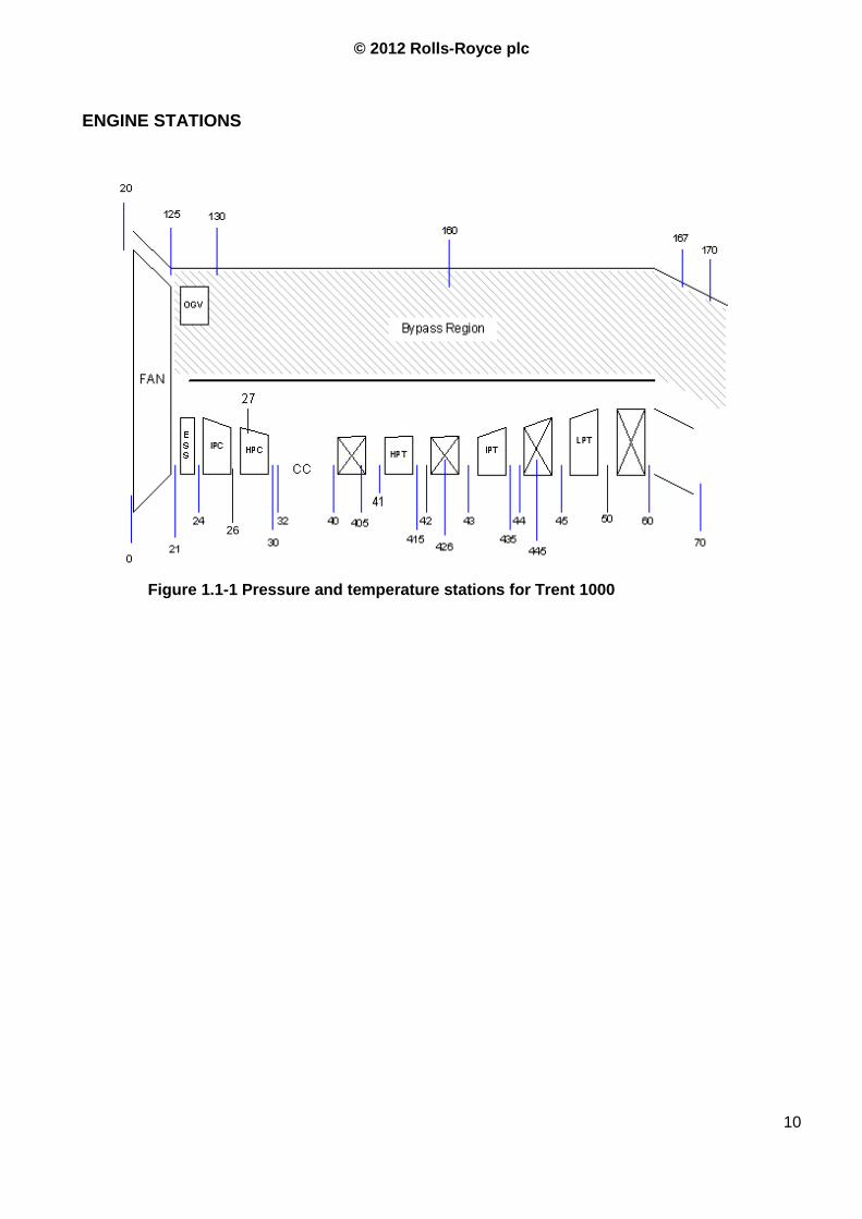
Figure 1.1-1 Pressure and temperature stations for Trent 1000 .............................................. 10
Figure 1.1-2 IP Power offtake system layout .......................................................................... 13
Figure 1.1-3 Trent 1000 AGB and accessories layout ............................................................ 14
Figure 1.1-4 Trent 1000 Engine cut-off ................................................................................... 15
Figure 1.2-5 Step load characteristics used to model transient loads ..................................... 17
Figure 1.3-6 Trent 1000 idle thrust estimation Vs. day temperature with different IP shaft SR 21
Figure 1.3-7 N3 and N2 variation with IP P/O for constant NMix ............................................. 23
Figure 1.5-14 Power offtake levels of different engines .......................................................... 29
Figure 1.5-15 P/O levels Vs. P/O architectures ...................................................................... 30
Figure 2.2-18 Effects of weight increase on fuel burn ............................................................. 35
Figure 2.3-20 Layout of the IP P/O with low speed mechanical clutch .................................... 37
Figure 2.3-21 VIGVs schedule for T1000, Cranking Vs High speed ....................................... 39
Figure 2.3-22 Starting procedure with IP P/O and dual starter (with coupling device). ............ 40
Figure 2.3-23 Starting procedure with IP shaft crank .............................................................. 41
Figure 2.3-25 Starting time requirement, temperature envelope ............................................. 44
Figure 2.5-26 Typical HP compressor map with constant speed and constant efficiency
iso-lines ................................................................................................................................ 47
Figure 2.5-27 Pressure conditions for turbines ....................................................................... 49
Figure 2.5-28 P/O effects on turbines' power .......................................................................... 52
Figure 2.6-29 Residual surge margin and threats to WL and surge line .................................. 54
Figure 2.6-30 Effects on the HPC working line: IP P/O and HP P/O ....................................... 55
Figure 2.6-31 Loop shaping of the HPC with IP P/O system ................................................... 56
Figure 2.6-34 Changes on IPC working line with IP or HP P/O system, HBV effect is shown for
Hp P/O ................................................................................................................................... 58
Figure 2.6-36 Effects of the switched air system on the HPC and IPC stability margin ........... 59
Figure 2.6-24 VSV open loop schedule .................................................................................. 61
Figure 2.6-25 IPC speed triangle control with VSV ................................................................. 62
Figure 2.6-39 Flowchart for HBR requirements ...................................................................... 65
Figure 2.8-42 Effect of bleed air on compressor stages .......................................................... 69
Figure 2.8-43 Effect of min P26/P44 on resulting thrust at low idle ......................................... 71
Figure 2.8-44 Cooling air flow as function of P26/P44 ............................................................ 71
Figure 2.8-45 Trent 1000 ESS anti iceing system ................................................................... 72
Figure 3.1-47 Solution definition procedure, logic scheme ...................................................... 76
Figure 3.1-48 Requirements flowdown diagram ..................................................................... 77
Figure 3.1-49 Solution definition using System Engineering, preliminary design tools ............ 77
Figure 3.1-50 The "W diagram" .............................................................................................. 78
Figure 3.2-51 Power Offtake System physical boundaries and interfaces (cyan balloons) ...... 80
Figure 3.2-52 IP power offtake context diagram ..................................................................... 81
Figure 3.2-53 Engine context diagram for systems related to the IP P/O system .................... 82
Figure 3.2-54 IP P/O system Function Flow Diagram ............................................................. 89
Figure 3.2-55 QFD1 structure ................................................................................................. 92
Figure 3.2-56 IP P/O system Functional Reqirements Tree (Red boxes are top-level functions)
............................................................................................................................................... 97

7
Figure 3.2-57 IP P/O system QFD1 results ............................................................................. 98
Figure 3.2-58 QFD1 results: System attributes rating ............................................................. 99
Figure 3.2-59 QFD1 results: Functional requirements rating .................................................. 99
Figure 6.6-60 Fluid coupling device ...................................................................................... 115
Figure 6.6-61 SAGB with breather, high speed fluid coupling device .................................... 117
Figure 6.6-62 SAGB, low speed fluid coupling device .......................................................... 119
© 2012 Rolls-Royce plc
©2012 Rolls-Royce plc
The information in this document is the property of Rolls-Royce plc and may not be copied, or communicated to a third party, or
used, for any purpose other than that for which it is supplied without the express written consent of Rolls-Royce plc.
Acronyms
A/C Aircraft
ACU Acceleration Control Unit
AFDX Avionics Full Duplex network
AGB Accessory Gearbox
Amb Ambient
AOHE Air Oil Heat Exchanger
APU Auxiliary Power Unit
B787 Boeing 787
BPR By-Pass Ratio
BV Bleed Valve
CACV Cooling Air Control Valve
CFB Centrifugal Breather
DP Differential Pressure
DPT Differential Pressure Transducer
EAI Engine Anti Ice
ECS Environmental Control System
EDP Engine Driven Pump (hydr.pump)
EDP Engine Development Program
EEC Engine Electronic Controller
EGT Exhaust gas Temperature
EIS Entry Into Service
EMI Electromagnetic Interference
EMU Engine Monitoring Unit
EPDC Electrical Power Distr. Centre
ESS Engine Section Stators
FAA Federal Aviation Administration
FADEC Full Authority Digital Engine Control
FBH Front Bearing Housing
fh flight hour
FOGV Fan Outlet Guide Vanes
FOHE Fuel Oil Heat Exchanger
HBV Handling Bleed Valve
GBX Gearbox
Gpm Gallons Per Minute
HBPR High BPR
HMU Hydro-Mechanical Unit
HP High Pressure
HPC High Pressure Compressor
HPT High Pressure Turbine
hp horse power
IFSD In Flight Shut Down
IGB Intermediate Gearbox
IGV Inlet Guide vane
IP Intermediate Pressure
IPC Intermediate Pressure Compr.
IPT Intermediate Pressure Turbine
IOM Input-Output Module
Kg Kilogram
KOZ Keep Out Zone
KT Knot
KVA Kilo Volt Ampere
Lbs Pounds
L/G Landing Gear
Lpm Liters per minute
LP Low Pressure
LPC Low Pressure Compressor
LPT Low Pressure Turbine
LPTCCV LPT Case Cooling Valve
LVDT Linear Variable Differ. Transducer
MCT Maximum Continuous Thrust
Mn Mach number
MoU Master of Understanding
MTBF Mean Time Between Failures
MTBR Mean Time Between Removals
MTO Maximum Take-Off
N1 (or NL) LP spool rotation speed
N2 (or NI) IP spool rotation speed
N3 (or NH) HP spool rotation speed
NM NMix rotation speed
NMDot Rate of change of NMix
OEI One Engine Inoperative
OGV Outlet Guide Vanes
P0 Ambient pressure
P160 Fan Exit Pressure
P24 Engine Intake Pressure
P26 IPC Exit Pressure
© 2012 Rolls-Royce plc
9
P30 HPC Delivery Pressure
P50 LPT exit pressure
Pamb Ambient pressure
PCE Pre cooler
PMA Permanent Magnet Alternator
P/O Power Off-take
Pph Pound Per Hour
Psi Pound per square inch
PWR Power
RAT Ram Air Turbine
RCI Resolve Customer Issue
RDC Remote Data Concentrator
RDS Radial Drive Shaft
R-R Rolls-Royce plc
RTO Rejected Take-Off
S/C Short Circuit
SAGB Step Aside Gear Box
SASV Secondary Air System Salves
SFC Specific Fuel Consumption
SID System Interface Document
SLS Sea Level Static
T/O Take Off
TBH Tail Bearing Housing
TCAF Turbine Cooling Air Front
TCAR Turbine Cooling Air Rear
TCC Turbine Case Cooling
TCCV Turbine Case Cooling Valve
TET Turbine Entry Temperature
TGT Turbine Gas Temperature
TOD Top Of Descent
VFG Variable Frequency Generator
VFSG Variable Frequency Starter Generator
WL Working Line
© 2012 Rolls-Royce plc
10
ENGINE STATIONS
Figure 1.1-1 Pressure and temperature stations for Trent 1000
26
© 2012 Rolls-Royce plc
11
Summary
The progressive increase of power extracted from the engine for the electrical aircraft has raised
the issue of the competitive position of 2-shaft vs. 3-shaft engines and, within the 3-shaft architecture,
the effects of using a different shaft to drive the accessory gearbox.
The aim of this report is to define the key parameters and features of an IP P/O system, how they
are influenced, what are the systems and stakeholders involved and, qualitatively, how they are
influenced. This is done in order to explain and better understand the decisions made during the
design and development of the T1000, why certain solutions have been selected and others rejected,
which areas of P/O design require particular attention and what are the lessons learnt.
The first part of this document is aimed at better understanding the theory and the rationale behind
the IP P/O system and its influences on the engine. In order to do this different topics are discussed,
starting from Load requirements, Idle setting, Engine weight, Fuel burn, Starting performance,
Thermodynamic and Mechanical aspects, Secondary air system features and Noise.
The second part is aimed at reviewing the design procedure using the Systems Thinking
approach, i.e. considering the P/O system not just as the sum of its components but as a system
with different properties, functions and effects. The review of the design process starts from the
Definition of Requirements, proceeds with the Stakeholders Analysis (only the most affected
are considered in detail) and ends with a review of the system on the actual engine (Trent 1000
Pack B): relation between requirements, functions and implementation, review of ERMS and
Lessons Learnt databases and FMECA report.

© 2012 Rolls-Royce plc
12
PART ONE – UNDERSTANDING OF THE IP POWER OFFTAKE SYSTEM
© 2012 Rolls-Royce plc
13
1.1 Introduction
The progressive increase of power extracted from the engine for the aircraft has raised the issue of
the competitive position of 2-shaft vs. 3-shaft engines since, as will be widely discussed later, the
former engines are less affected by this change. For the 3-shaft engines this resulted in the
requirement of using a different shaft to drive the accessory gearbox.
With the term “power offtake system” we refer to the whole of the parts, mechanisms and functional
systems that allow taking the power from the core of the engine and making it available for the
accessory gearbox (AGB). The main assemblies that constitute the P/O system are the Internal Gear
Box (IGB), the Step Aside Gear Box (SAGB) and the External Gear Box (EGB). The External Gear
Box (EGB) is the assembly of Transfer Gear Box (TGB) and Accessories Gear Box (AGB). Although
the turbine and the core shaft are not considered as part of the P/O system, but they are required to
extract the thermal power from the gas flow, convert it into mechanical power and transfer it to the
IGB.
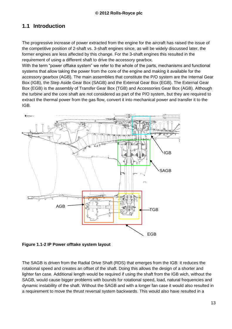
The SAGB is driven from the Radial Drive Shaft (RDS) that emerges from the IGB: it reduces the
rotational speed and creates an offset of the shaft. Doing this allows the design of a shorter and
lighter fan case. Additional length would be required if using the shaft from the IGB wich, without the
SAGB, would cause bigger problems with bounds for rotational speed, load, natural frequencies and
dynamic instability of the shaft. Without the SAGB and with a longer fan case it would also resulted in
a requirement to move the thrust reversal system backwards. This would also have resulted in a
AGB
EGB
TGB
SAGB
IGB
Figure 1.1-2 IP Power offtake system layout
© 2012 Rolls-Royce plc
14
longer and heavier nacelle and a potential increase in drag. Moreover, reducing the shaft speed
provide a solution to some important problems. Connecting the IGB directly to the TGB would have
required a very long shaft rotating at high speed. This would have been problematic from the
prospective of its dynamic behaviour.
It will be evident from the next chapters why the design of the RDS and the SAGB has been crucial
for the development of the IP P/O system.
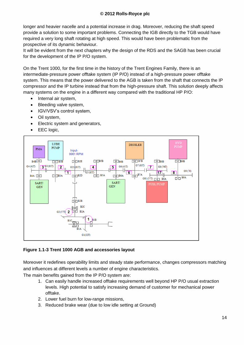
On the Trent 1000, for the first time in the history of the Trent Engines Family, there is an
intermediate-pressure power offtake system (IP P/O) instead of a high-pressure power offtake
system. This means that the power delivered to the AGB is taken from the shaft that connects the IP
compressor and the IP turbine instead that from the high-pressure shaft. This solution deeply affects
many systems on the engine in a different way compared with the traditional HP P/O:
Internal air system,
Bleeding valve system,
IGV/VSV‟s control system,
Oil system,
Electric system and generators,
EEC logic,
Figure 1.1-3 Trent 1000 AGB and accessories layout
Moreover it redefines operability limits and steady state performance, changes compressors matching
and influences at different levels a number of engine characteristics.
The main benefits gained from the IP P/O system are:
1. Can easily handle increased offtake requirements well beyond HP P/O usual extraction
levels. High potential to satisfy increasing demand of customer for mechanical power
offtake.
2. Lower fuel burn for low-range missions,
3. Reduced brake wear (due to low idle setting at Ground)
Angled Drive shaft
© 2012 Rolls-Royce plc
15
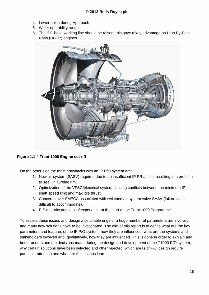
4. Lower noise during Approach,
5. Wider operability range,
6. The IPC base working line should be raised; this gave a key advantage on High By-Pass
Ratio (HBPR) engines.
On the other side the main drawbacks with an IP P/O system are:
1. New air system (SASV) required due to an insufficient IP PR at idle, resulting in a problem
to seal IP Turbine rim,
2. Optimization of the VFSG/electrical system causing conflicts between the minimum IP
shaft speed limit and max idle thrust,
3. Concerns over FMECA associated with switched air system valve SASV (failure case
difficult to accommodate),
4. EIS maturity and lack of experience at the start of the Trent 1000 Programme
To assess these issues and design a certifiable engine, a huge number of parameters are involved
and many new solutions have to be investigated. The aim of this report is to define what are the key
parameters and features of the IP P/O system, how they are influenced, what are the systems and
stakeholders involved and, qualitatively, how they are influenced. This is done in order to explain and
better understand the decisions made during the design and development of the T1000 P/O system,
why certain solutions have been selected and other rejected, which areas of P/O design require
particular attention and what are the lessons learnt.
Figure 1.1-4 Trent 1000 Engine cut-off
© 2012 Rolls-Royce plc
16
1.2 Load requirements
1.2.1 Interaction with the aircraft
The Trent 1000 has been designed and optimized to power the new Boeing 787. In order to
achieve the task of improving overall efficiency of the aircraft, Boeing made a decision towards the
“More Electric Concept”. This culminates in a requirement for the engine manufacturer to provide a
significantly larger amount of electric power via the external gearbox. For instance, the T1000 has
to provide power to a novel aircraft-mounted electric Environmental Control System (ECS), which
would have been existed in the form of a traditional bleed air system on recent Trent engines. This
system now comprises two fuselage mounted air conditioning and pressurization packs that are
driven by electric motors. This means that the P/O system has to provide the additional power
required by the Air Conditioning Packs. The main difference for a More Electric Engine is that
bleed air is only used for engine internal use (engine secondary air system) and to guarantee the
operability of the engine over a wider range (Handling Bleed Valves, HBV‟s).
One Engine Driven Hydraulic Pump (EDP) and two Variable Phase Starter Generators (VFSG‟s)
are mounted on each engine in order to provide the required power for the ECS packs. In
conjunction with the other core driven accessories (oil pump, fuel pump and oil breather) this
requires the P/O system to deliver a significant amount of power to the EGB during normal
operation. This was the first estimation of the power required from the aircraft. The “More Electric
Aircraft” was a very new concept and there was a small margin of confidence with the actual
requirements of such a configuration. The power requirements have largely evolved during the
development of the Trent 1000 programme, leading to a maximum peak value of more than
1100hp to be delivered by a single engine.
1.2.2 Normal conditions
The typical power extraction levels have been identified for different flight phases for a 3000nm flight
for a B787-8, with 223 and 371 passengers. Data are property of Rolls Royce plc.
Data removed
1.2.3 Max conditions / peak levels
The max load conditions are defined as maximum loads and hold time. Typical hydraulic pump loads
are less than one 10th of the VFSG power, except during certain conditions occurring at high engine
power when loads up to 120% of the nominal load can occur.
The engine and the power offtake system must be designed to accommodate the transient loads
defined in Errore. L'origine riferimento non è stata trovata. without suffering mechanical damage,
reduced drive train components‟ life and without threatening the engine stability. The worse situation
© 2012 Rolls-Royce plc
17
for all conditions is the direct short (DS, i.e. short circuit). A 5 second sustained overload is required
for the system to recognise and isolate this fault, during this period the electric system has to provide
the maximum power required. Data are property of Rolls Royce plc.
1.2.4 Transient loads
The power offtake system has to cope with shocks and transitory load due to:
Normal load variation, i.e. activation of wing ice protection system or high load condition for
the A/C packs (aircraft on ground during a hot day)
Abnormal loads, i.e. failure of a part of the electric system
Starter.
The hydraulic pump and the fuel pump also require variable amounts of power but their variation is
one order of magnitude smaller than the electric demand fluctuation.
For transient step loads a dynamic factor applies (Ref. 1)
The system must stand shocks and rapid changes of load without diminishing the predicted life and
reliability. This can ultimately lead to an increase in the system‟s weight. Further work should be done
as part of an improvement task in order to reduce the rate of change of loads and avoid predictable
shocks.
From the performance point of view the engine shall demonstrate uniform Engine-to-Engine and
Control-to-Engine acceleration and deceleration rates with any combinations of normal level of bleed
and power extraction with an acceptable deviation from a reference value of acceleration rate.
The difference between the normal load and the peak load has a much deeper impact on idle setting
and performance: if a power load signal would be available than it would be possible to optimize the
control system for best SFC when there is no load. It would also remove problems with load peaks
because it would be possible to “prepare the engine” for such loads. Without this kind of control the
engine has to be designed and the idle condition be settled considering the worst-case load step,
which is usually an almost impulsive peak load.
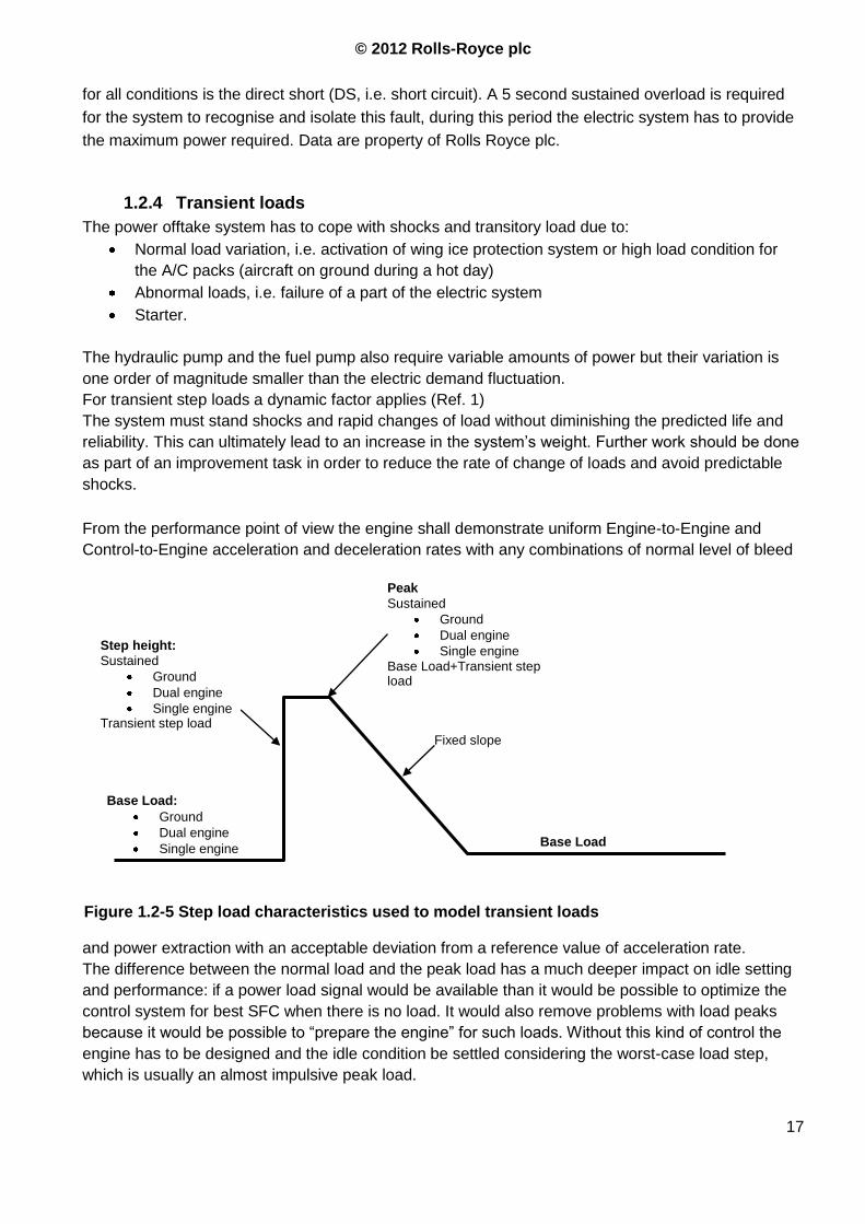
Figure 1.2-5 Step load characteristics used to model transient loads
Base Load:
Ground
Dual engine
Single engine
Step height:
Sustained
Ground
Dual engine
Single engine Transient step load
Peak
Sustained
Ground
Dual engine
Single engine Base Load+Transient step load
Base Load
Fixed slope

© 2012 Rolls-Royce plc
18
In order to assess the operability and the transient behaviour of the engine the time variation law of
the applied load has to be defined. The wave shape used for the Trent 1000 is shown in Figure 1.2-5.
There is no Environment Control System (ECS) bleed on the Trent 1000 engine; the VFSG‟s have to
provide the electric power for two A/C units installed on the aircraft also during one engine inoperative
(OEI) condition, there is therefore a need for a robust operability with high power load.
As the P/O level increases, its influence on the whole engine becomes more and more important
and the engine has to be optimized around the offtake level to reach the best performance. For
instance having a robust load signal would allow R-R to lower the idle speed and increase it only
when needed, e.g. only raise it when the anti-icing system is turned at idle condition.
On the Trent 1000 design, some conservatism has been taken because of the novelty of the P/O
system. Introducing other new devices, systems or control logic would have resulted in an
excessive risk level due to new failure modes. To improve reliability and robustness of the system
the EEC doesn‟t receive a control signal from the aircraft. The pressure ratio P30/P26 is used by
the EEC since this can be related to the extracted power. For future engines a monitoring system
should be desired if margin for max P/O is required to maintain a low minimum idle thrust.
Requirements for a better control of idle are extensively discussed between Performance, Fluid
System and IPTs but requirements for the design of the P/O system may be raised by other crucial
engine systems to define how to interact with the P/O.
1.2.5 Maximum P/O level for an IP/HP/LP system
There is not a unique and precise limit for the power that can be extracted with an HP or an IP P/O
system; everything depends on a trade off study and on the performance required by the customer as
operability, min and max thrust, overhaul intervals etc. The constrains of the system can be related
with the P/O level but this is not an easy problem and the answer depends on core size,
requirements, transient behaviour etc. The best thing to do this is express the extracted power as
percentage of the turbine power in a specific condition (e.g. MTO) to have an idea of how much the
core is affected by the power extraction. To compare P/O effects on surge margin at different
conditions one has to use the operative turbine power.
For instance, a binding condition could be the generator speed or the HPC/IPC surge margin but
there are also the air system related issues and other constrains that are not uniquely defined. Which
of these is the relevant design constraint depends on requirements and operative condition of the
engine. The next chapters are aimed at describing what the differences between IP P/O and HP P/O
are in different conditions like idle and throttle response.
For both the systems, IP and HP P/O, we can roughly say that the maximum power that can be
extracted can be expressed as a percentage of the turbine power. The percentage value is almost
independent on the shaft used for extraction.
It is not possible to define the limits for either system in a simple and straightforward way. Obtaining a
more accurate answer requires use of a performance model able to predict the stability margins for
each system.
A smart parameter to relate with the P/O is the core turbine power or the shaft turbine power.
During the preliminary design is fundamental to understand the relationship between P/O demand,
engine size, stability and other engine functions or constraints in order to work out an optimum
solution for the power offtake system, i.e IP or HP powered, to obtain a robust engine.
© 2012 Rolls-Royce plc
19
1.2.6 Requirements:
1. Maintain margin on efficiencies and sizing to avoid shortfalls and to allow refinement of the
design during EDP: More Electric Engine is a relatively new concept (see both cases T1000
and XWB)
2. Design for max load considering both steady state and transient, consider normal and
exceptional overloads
3. Modify VFSG control system and transient behaviour, 1.9 transient factor for step loads will no
longer be acceptable: it has a too strong impact on idle setting. Consider for custom design of
generators.
4. Performance need to push for a “load state” and “upcoming load” signals, reduce engine
weight and allow to redefine idle
5. Hydraulic loads are much smaller and more constant than electrical loads.
6. Consider shocks resulting from sudden application of load during transient operation and
during starting crank. These include switching anti-icing devices, faults on aircraft systems and
other conditions reported in Ref. 1.
7. Satisfy engine to engine and control to engine acceleration and deceleration rate
8. Compressor stability has to facilitate all IP P/O levels and scenarios at all engine conditions.
© 2012 Rolls-Royce plc
20
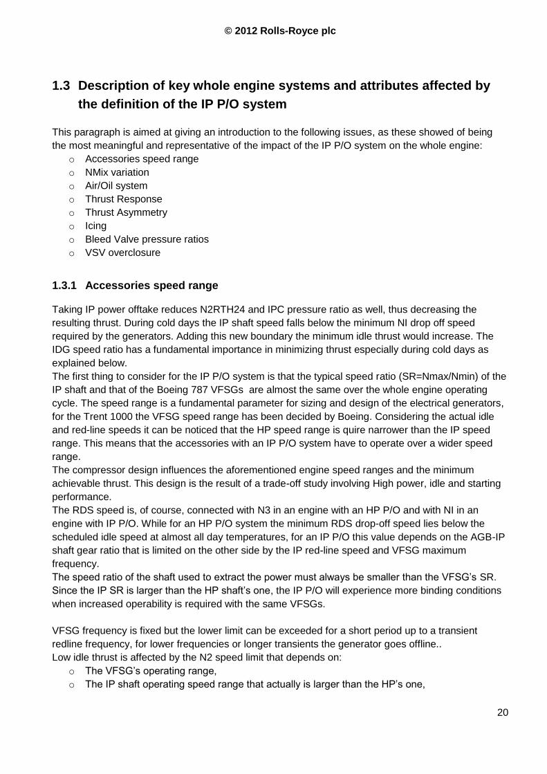
1.3 Description of key whole engine systems and attributes affected by
the definition of the IP P/O system
This paragraph is aimed at giving an introduction to the following issues, as these showed of being
the most meaningful and representative of the impact of the IP P/O system on the whole engine:
o Accessories speed range
o NMix variation
o Air/Oil system
o Thrust Response
o Thrust Asymmetry
o Icing
o Bleed Valve pressure ratios
o VSV overclosure
1.3.1 Accessories speed range
Taking IP power offtake reduces N2RTH24 and IPC pressure ratio as well, thus decreasing the
resulting thrust. During cold days the IP shaft speed falls below the minimum NI drop off speed
required by the generators. Adding this new boundary the minimum idle thrust would increase. The
IDG speed ratio has a fundamental importance in minimizing thrust especially during cold days as
explained below.
The first thing to consider for the IP P/O system is that the typical speed ratio (SR=Nmax/Nmin) of the
IP shaft and that of the Boeing 787 VFSGs are almost the same over the whole engine operating
cycle. The speed range is a fundamental parameter for sizing and design of the electrical generators,
for the Trent 1000 the VFSG speed range has been decided by Boeing. Considering the actual idle
and red-line speeds it can be noticed that the HP speed range is quire narrower than the IP speed
range. This means that the accessories with an IP P/O system have to operate over a wider speed
range.
The compressor design influences the aforementioned engine speed ranges and the minimum
achievable thrust. This design is the result of a trade-off study involving High power, idle and starting
performance.
The RDS speed is, of course, connected with N3 in an engine with an HP P/O and with NI in an
engine with IP P/O. While for an HP P/O system the minimum RDS drop-off speed lies below the
scheduled idle speed at almost all day temperatures, for an IP P/O this value depends on the AGB-IP
shaft gear ratio that is limited on the other side by the IP red-line speed and VFSG maximum
frequency.
The speed ratio of the shaft used to extract the power must always be smaller than the VFSG‟s SR.
Since the IP SR is larger than the HP shaft‟s one, the IP P/O will experience more binding conditions
when increased operability is required with the same VFSGs.
VFSG frequency is fixed but the lower limit can be exceeded for a short period up to a transient
redline frequency, for lower frequencies or longer transients the generator goes offline..
Low idle thrust is affected by the N2 speed limit that depends on:
o The VFSG‟s operating range,
o The IP shaft operating speed range that actually is larger than the HP‟s one,
© 2012 Rolls-Royce plc
21
o IGB speed ratio SR=N2_Redline/N2_idle with N2_Redline
On actual engine the IP SR is slightly smaller than the VFSG‟s one, this because some margin is
required to tolerate overspeed and sub-idle speeds. On the first T1000 engines the Generator
frequency range was shifted towards larger N2. By modifying the gear ratio between the NI spool and
the generator through an SAGB redesign this range of speeds had been moved towards smaller
values of N2 which would allow for a reduction in the idle setting.
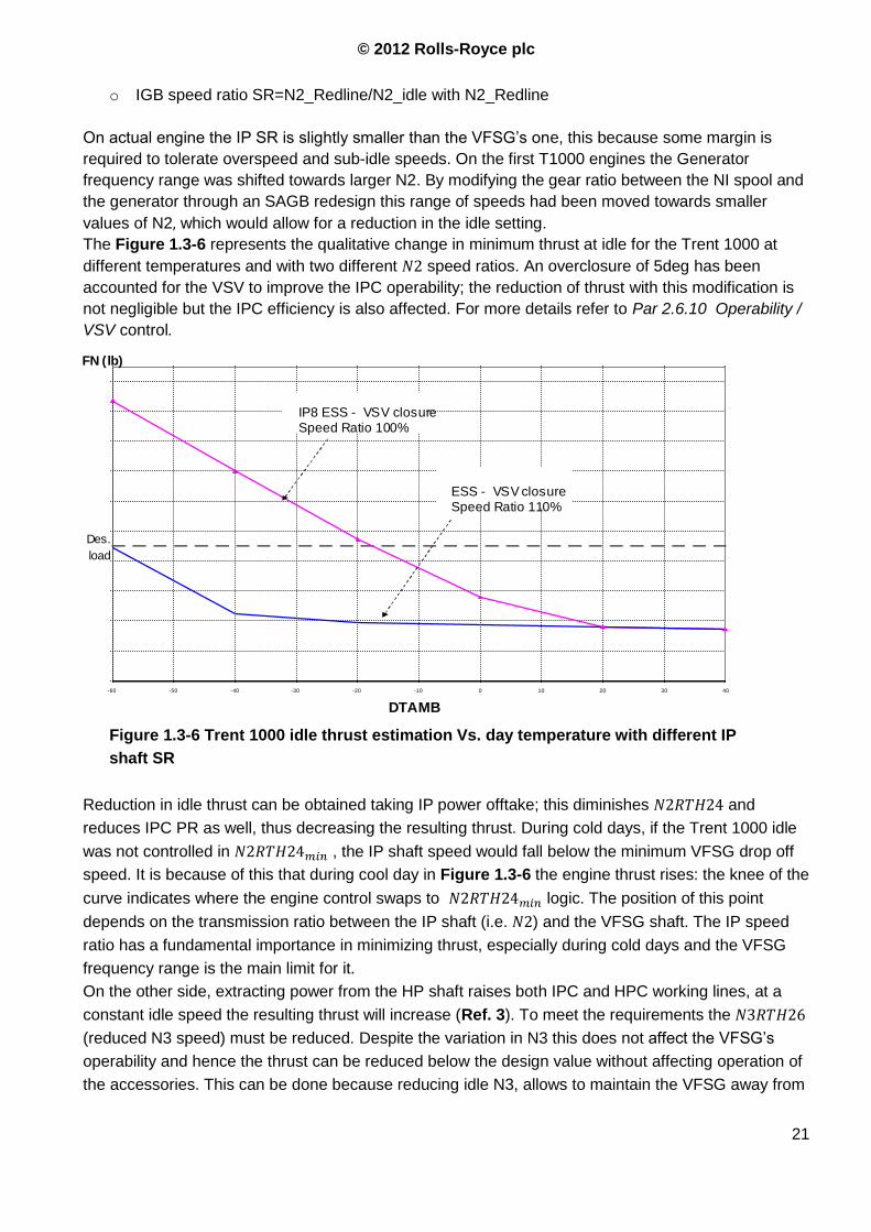
The Figure 1.3-6 represents the qualitative change in minimum thrust at idle for the Trent 1000 at
different temperatures and with two different speed ratios. An overclosure of 5deg has been
accounted for the VSV to improve the IPC operability; the reduction of thrust with this modification is
not negligible but the IPC efficiency is also affected. For more details refer to Par 2.6.10 Operability /
VSV control.
Reduction in idle thrust can be obtained taking IP power offtake; this diminishes and
reduces IPC PR as well, thus decreasing the resulting thrust. During cold days, if the Trent 1000 idle
was not controlled in , the IP shaft speed would fall below the minimum VFSG drop off
speed. It is because of this that during cool day in Figure 1.3-6 the engine thrust rises: the knee of the
curve indicates where the engine control swaps to logic. The position of this point
depends on the transmission ratio between the IP shaft (i.e. ) and the VFSG shaft. The IP speed
ratio has a fundamental importance in minimizing thrust, especially during cold days and the VFSG
frequency range is the main limit for it.
On the other side, extracting power from the HP shaft raises both IPC and HPC working lines, at a
constant idle speed the resulting thrust will increase (Ref. 3). To meet the requirements the
(reduced N3 speed) must be reduced. Despite the variation in N3 this does not affect the VFSG‟s
operability and hence the thrust can be reduced below the design value without affecting operation of
the accessories. This can be done because reducing idle N3, allows to maintain the VFSG away from
Des.
load
-60 -50 -40 -30 -20 -10 0 10 20 30 40 DTAMB
FN (lb)
IP8 ESS - VSV closure Speed Ratio 100%
ESS - VSV closure Speed Ratio 110%
Figure 1.3-6 Trent 1000 idle thrust estimation Vs. day temperature with different IP
shaft SR
© 2012 Rolls-Royce plc
22
its drop-off speed because the generator SR1 is still larger than N3 SR. The binding condition for an
engine with an HP P/O system and high power extraction is likely to become the IPC stability margin
which in turn may require a bigger core size or a redesign of the PR split between the compressors.
This can take away the advantage of the hypothetical benefit from a larger speed margin
With an IP P/O, the speed of the electrical generators and P/O limitations can ultimately limit Ground
Idle reduction, the recovery though generators with a wider speed range is the subject of a current
R&T programme.
1.3.2 NMix variation
Considering the situation of having Low and High idle scheduled through corrected NMix rather than
allows to define a value for NMix that meets the compressor stability requirements and another
that meets the minimum Air System pressure ratio.
The effects of altitude, Mach number, day temperature and power offtake on the idle setting
parameters have to be assessed (Ref. 11).
Day temperature has not a relevant effect on HPC and IPC working line or on WRTP/corr_NMix
relationship that are instead affected by Mach number and altitude. These effects are due to
beneficial influence of a higher Reynolds number for the compressor/turbine efficiency and, assuming
the turbine being not choked, to the variation of the work split.
The main parameter affecting working lines and WRTP/NMix on both IP and HP P/O is the power
offtake level, its effect at idle is still more pronounced taking a larger amount of the total Turbine
power (as widely explained in Effects of the IP P/O system on thermodynamic aspects).
Analysis of the idle thrust for the Trent1000 at different altitudes, Mach number and day temperatures
showed that the highest thrust was reached at the sea level static condition (higher mass flow), the
NMix idle schedule can be defined at SLS but altitude and Mach number dependency is needed in the
schedule in order to cover the entire flight envelope. If the power offtake level signal is not available
design for worst condition is required (consistently with aircraft manufacturer specifications) (Ref. 11).
The minimum corrected NMix limiter could be set at the point of minimum required compressor
stability but, on the Trent 1000, this constraint hides behind the minimum generator speed.
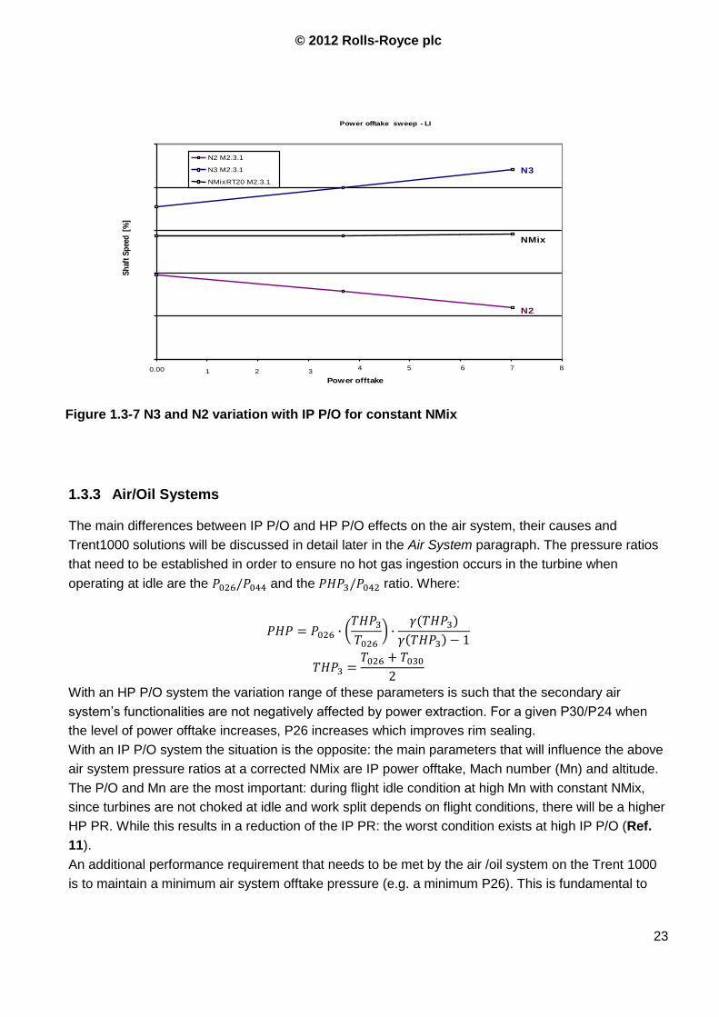
With an IP P/O system at a constant corrected NMix as power offtake is gradually increased N2
speed will decrease linearly (see Figure 1.3-7) while N3 will increase. Consequently, the minimum
corrected NMix schedule is defined to ensure that when maximum power offtake is being demanded
the engine operates on the intersection between the minimum N2 limiter (due to generators) and the
minimum corrected NMix (for core stability). This has the additional benefit of maintaining high levels
of N2 speed when no power offtake is demanded which will allow the engine to cope with a sudden
load addition and the subsequent N2 dip maintaining N2 speed above the minimum generator
frequency. On the other side this limit affects idle thrust control and fuel burn (see previous
paragraph).
For an HP P/O system the N2 and N3 lines converges as the power extracted increases. Indeed the
HP shaft speed is reduced while the IP shaft accelerates to maintain constant NMix.
1 Speed Ratio
© 2012 Rolls-Royce plc
23
1.3.3 Air/Oil Systems
The main differences between IP P/O and HP P/O effects on the air system, their causes and
Trent1000 solutions will be discussed in detail later in the Air System paragraph. The pressure ratios
that need to be established in order to ensure no hot gas ingestion occurs in the turbine when
operating at idle are the and the ratio. Where:
With an HP P/O system the variation range of these parameters is such that the secondary air
system‟s functionalities are not negatively affected by power extraction. For a given P30/P24 when
the level of power offtake increases, P26 increases which improves rim sealing.
With an IP P/O system the situation is the opposite: the main parameters that will influence the above
air system pressure ratios at a corrected NMix are IP power offtake, Mach number (Mn) and altitude.
The P/O and Mn are the most important: during flight idle condition at high Mn with constant NMix,
since turbines are not choked at idle and work split depends on flight conditions, there will be a higher
HP PR. While this results in a reduction of the IP PR: the worst condition exists at high IP P/O (Ref.
11).
An additional performance requirement that needs to be met by the air /oil system on the Trent 1000
is to maintain a minimum air system offtake pressure (e.g. a minimum P26). This is fundamental to
Figure 1.3-7 N3 and N2 variation with IP P/O for constant NMix
Power offtake sweep - LI
0.00 1 2 34 5 6 7 8
Power offtake
Sh
aft
Sp
eed
[%
]
N2 M2.3.1
N3 M2.3.1
NMixRT20 M2.3.1
NMix
N2
N3
© 2012 Rolls-Royce plc
24
ensure that the bearing chambers buffers are correctly pressurised and pressure drops across oil
seals are such that oil leaks do not occur.
The pressure drop limit depends on the sealing technology used on the current Trent 1000: oil seals
are unable to withstand negative pressure drops, especially at low speed.
Low P26 on Trent 1000 can affect oil scavenge capability, reducing pressure difference between
bearing chamber and scavenge pump. Breather efficiency can be affected by this situation.
1.3.4 Thrust Response
Since idle schedule with IP P/O requires different settings than with HP P/O it is recommended that
once Performance have set the preliminary minimum limiters (P26/P44, N2_idle, NMix, P30 and
others listed in Table 2.4-1) are defined, transient performance team tests the Acceleration Control
Unit (ACU) schedule to check whether the acceleration thrust response requirements are met. The
transient behaviour with an IP P/O system is quite different from those with HP P/O since the binding
conditions are different: the worst case for the HP power extraction system is with no power offtake
since the IP shaft in this condition has a very low rotating speed. With the IP P/O the IP shaft is slower
when a high level of power is extracted. In both cases the idle thrust increases when a larger amount
of power is extracted from the core. This might lead to an iterative process by which the Low Idle and
High Idle settings as well as the ACU loop are redefined to ensure both the thrust response
requirements and the compressor stability requirements are met.
1.3.5 Thrust Asymmetry
As said above, for an IP P/O system the idle NMix schedule is currently set as a constant NMix, which
means N2 decreases with increasing power offtake. If engine load is greater than a threshold amount
the engine will be operating on the Minimum N2 loop in order to maintain generator speed and NMix
will increase. Modifying the shaft speed will change the „starting point‟ on the Acceleration schedule
and the two engines will start from different points. In order to minimize thrust asymmetry the
acceleration of the engines should be scheduled using the same parameters used to define Low and
High Idle and ensuring that the acceleration phase starts from the same point for all the engines. If the
idle is settled using NMixRTHT24 the ACU (Acceleration Control Unit) has to use the loop based on
Nmix.Dot Vs. NMixRTHT24. This is possible and gives good results only if idle conditions of all
engines are defined using the same parameters and the min limiter, otherwise it would lead to
different starting point with different transient behaviour. It is thus important that all the engines are
controlled with the same schedule when on the ground, in this case the resulting thrust asymmetry will
depend only on the engine deterioration and engine-to-engine variation.
For engines with HP P/O systems controlled in constant NMix there is no such kind of problem since
switching to minN3 logic is not required not even for high levels of power extraction
© 2012 Rolls-Royce plc
25
1.3.6 Icing
High bypass engines like the T1000 have a very low fan PR at idle, this corresponds to a small
temperature rise across the fan that can result in ice growth on ESS and VIGVs. With future IP P/O
engines this problem will become even more evident since this system allows for higher BP ratios with
lower pressure ratios (i.e. bigger fan for same core size, as explained in Par.2.6.8). HP P/O limits the
achievable bypass ratio since the IPC has to maintain a larger surge margin. This means that with the
same hardware the IPC pressure ratio has to be reduced if an HP P/O system is installed on the
engine to reduce the working line and increase the surge margin. In order to obtain an acceptable
cycle efficiency the fan PR cannot become too small as there are no improvement margins for the
HPC PR with current designs whilst with an IP P/O this pressure shortfall can be recovered through
the IPC.
1.3.7 Bleed valve PR
It is possible that with an IP P/O system once the idle settings have been defined the resulting
pressure ratios across the IP8 bleed valves at a number of flight conditions is not high enough to force
them to open once commanded because of P26 being too low. These cases will need to be assessed
in detail by the HBV system owner to determine whether or not bleed valve opening capability at idle
is required at these conditions (Ref. 19).
On HP P/O engines the lowest P26 at idle is obtained without P/O. If idle with no power extraction is
considered as the design condition for the bleed valve system then the engine will not suffer for this.
1.3.8 VSV overclosure
The VSV overclosure is aimed at reducing the IPC PR when a high value of this parameter is not
required or is detrimental for the engine performance.
1.4 Mechanical aspects
1.4.1 Shaft critical speed
On the first design of the Trent 1000 a certain seto of gear ratios have been used (Ref. 4) in order to
achieve the starting speed ratio SR=NI
NH requested by the performance team without excessively
compromise the layout and the design of the central bearing house. The following rotation speed have
been obtained:
The speed difference between the IP and HP radial drive shaft cannot be undertaken. This speed
difference, in conjunction with the max rotation speed of the two shafts and gears, could create
problems related to:
© 2012 Rolls-Royce plc
26
Critical shaft speed
SAGB/IGB oil and Windage heat
Bearing lubrication and minimum load
Coupling device control (only early T1000)
Coupling device complete disengagement and heat (only early T1000)
The last two points only exist if a coupling device is used to start the engine. The image below shows
the layout of the IGB/SAGB with a hydraulic coupling device. Note that the design of the centre
bearing house requires modifications (1inch lengthier) to create the space for the HPC gear, required
as part of the start system.
The mechanical instability of a rotating shaft depends on the so-called Whirling Constant which is
proportional to 2
L
. To have a rough idea of the effective importance of the rotational speed on the
RDS we can compare the whirling constants of different engines.
The absolute value of the whirling constent alone doesn‟t identifies the problem, however the mutual
interaction of the two shafts and the effective dynamic behaviour needs to be analyzed for each
configuration in order to avoid resonance or other unexpected loads. This is one of the requirements
for the mechanical design of the P/O system, irrespective of IP or HP driven.
1.4.2 SAGB/IGB heat management and Windage
The windage effect is energy transfer to or from a fluid as a result of drag either from viscous effects
or by form drag from, for example, surface protrusions. This energy transfer is manifested in two
ways:
o A change in the whirl velocity of the fluid
o A change in the static enthalpy (or static temperature) of the fluid.
Windage power is proportional to 3shaftspeed
5_ radiusdisc
It is strongly influenced by protrusions and swirl velocity of air in the cavity.
Since the windage effect is proportional to35 rpmdiameter , reducing the diameters of the gears or
their width has a very important effect on the generated heat. Redesign of local layout, i.e. gear type
and size, could be considered in order to achieve this task.
Note that rotating components see a relative gas velocity so will not see the Total temperature in the
non-rotating (measured) frame of reference.
Free disk windage 58.2Relog491.0mC
© 2012 Rolls-Royce plc
27
535.0 r
erWindagepowCm
Consider that in this formula Re depends on the teeth dimensions.
“Heat to Oil" within the IGB and SAGB was one of the largest concerns with the HP/IP dual drive
solution on the early T1000 engines. The main risks were oil degradation and coking caused by high
HTO and ineffective oil scavenging due to accumulation of oil lumps around the scavenge ports. The
extra heating of a second set of bevel gears and set of bearings is evaluated based upon Trent 500
experience in an internal memo by N.Fomison and on Ref. 32. The overall design requirement was to
improve the effectiveness of the IGB scavenge system and to generate no more windage heating
than the Trent 500. On actual Trent 1000 engines the higher heat generated is mainly due to the
bigger gears, bearings and contact force. To minimize the windage effects and drain the hot oil
directly to the scavenge oil system shrouds have been designed around the gears.
1.4.3 Effects of higher torque
The Trent 1000 has experienced problems due to VFSG failures. This happened early in the
programme and raised reliability concerns. Taking power from a shaft at lower rpm means more
torque and transient loads with very a high impact energy (which compromises the mechanical life of:
bearings, gears, shafts…). This needs to be considered by the design of the IP P/O system. Another
not negligible problem related with the failure of a VFSG, or the failure of another accessory, is the
containment of debris. In event of a failure of an accessory, for instance a pump seizes, the “slingshot
effect” on the gear train is stronger with an IP P/O system due to the higher involved torque.
1.4.4 Resonance during surge events
The most important mechanical excitation for the IP P/O system is a high power surge event. During
this situation the IP system excites the P/O drive train with a very high torque with a frequency that is
close to the drive train‟s natural frequency. The first natural frequency of the HP system is many
hundreds of Hz instead that of the IP. This is because the IP system is less stiff and heavier, hence
the gear train responds with non negligible deformations. On a Development engine an IGB bevel
gear broke because these loads had not been considered. Another important aspect is that when the
engine surges, the HP speed doesn‟t change significantly, whereas the IP speed changes a lot. This
is why the net pressure (and air density) in the HPC educes while the IPC pressure (and density)
rises. With larger VFSG‟s inertia and two generators per engine, high power surge can exert a
significantly higher running torque on the system, which must be considered in the design. Hamilton
Sundstrand‟s dynamic modelling of the Trent 1000 drivetrain showed large dynamic torques occurring
when the engine is subjected to high power IP surge. A safety factor, compared to the nominal
maximum load, has been found on the Trent 1000. The effects of surge can be more pronounced in
the internal gearbox than the transfer gearbox (Ref. 30, Ref. 31) .
© 2012 Rolls-Royce plc
28
1.4.5 Sustained Torsional Oscillations (STO)
There is also an issue related with to vibrations caused by the electric generators. The generator
produces a constant frequency electrical output. In order to do this the VFSGs are controlled by an
electronic device that uses the PMA signal as input. When the input speed changes the effect of this
system is a variation of the torque required by the VFSGs, which in turn results in a change of N2.
The properties of this closed loop control system, due to the interaction of torque variation and IP P/O
system mechanical behaviour, could lead to undamped torsional oscillations. This is likely to result in
a problem for the generator in achieving a steady state condition for the required torque (Ref. 29). As
stated above the first torsional mode of the IPC, IPT and shaft is very close to the frequency of the
VFSG control signal.
Boeing are using the Permanent Magnet Generator PMG output voltage as a speed signal, which is a
3 phase electric signal. Its frequency is three times the IP shaft rotational speed, e.g. - 60% N2 =
9,000rpm VFSG speed = 150Hz x 3 = 450Hz signal).
Torsional oscillations (STO) have been measured by the testing team as a variation in the frequency
of the PMG signal, for Ground idle:
55%N2, 400Hz PMG signal
+/- 2Hz Signal oscillation: 398 – 402Hz, Hz4
Frequency of oscillation = 25Hz (Natural frequency of mechanical system)
Resultant VFSG shaft torque equivalent to +/- kWW 80
These values were taken from a Boeing presentation. It is possible to compute the allowable steady
state torque AllowableM (being MW where30
rpm ) as:
MMM alNoAllowable min
Assuming an idle condition with the system rated at 250kW @ 60%N2 (i.e. 250kW are required by the
A/C systems), is a very conservative assumption since the maximum extraction is higher than 750kW
per engine.
1.5 Main drives to move from an HP P/O system to an IP P/O system
1.5.1 Introduction
In the first part of this paragraph a comparison between different engines and their P/O levels will be
carried out. The engines considered are other Trent family engines and the General Electric GEnx. In
the second part the XWB approach to the P/O system will be illustrated in order to understand the
problems involved with an HP P/O system when high power levels are required from the accessory
gearbox.
© 2012 Rolls-Royce plc
29
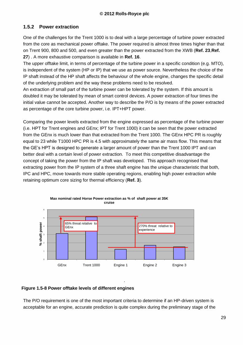
1.5.2 Power extraction
One of the challenges for the Trent 1000 is to deal with a large percentage of turbine power extracted
from the core as mechanical power offtake. The power required is almost three times higher than that
on Trent 900, 800 and 500, and even greater than the power extracted from the XWB (Ref. 23,Ref.
27) . A more exhaustive comparison is available in Ref. 16.
The upper offtake limit, in terms of percentage of the turbine power in a specific condition (e.g. MTO),
is independent of the system (HP or IP) that we use as power source. Nevertheless the choice of the
IP shaft instead of the HP shaft affects the behaviour of the whole engine, changes the specific detail
of the underlying problem and the way these problems need to be resolved.
An extraction of small part of the turbine power can be tolerated by the system. If this amount is
doubled it may be tolerated by mean of smart control devices. A power extraction of four times the
initial value cannot be accepted. Another way to describe the P/O is by means of the power extracted
as percentage of the core turbine power, i.e. IPT+HPT power.
Comparing the power levels extracted from the engine expressed as percentage of the turbine power
(i.e. HPT for Trent engines and GEnx; IPT for Trent 1000) it can be seen that the power extracted
from the GEnx is much lower than that extracted from the Trent 1000. The GEnx HPC PR is roughly
equal to 23 while T1000 HPC PR is 4.5 with approximately the same air mass flow. This means that
the GE‟s HPT is designed to generate a larger amount of power than the Trent 1000 IPT and can
better deal with a certain level of power extraction. To meet this competitive disadvantage the
concept of taking the power from the IP shaft was developed. This approach recognised that
extracting power from the IP system of a three shaft engine has the unique characteristic that both,
IPC and HPC, move towards more stable operating regions, enabling high power extraction while
retaining optimum core sizing for thermal efficiency (Ref. 3).
.
The P/O requirement is one of the most important criteria to determine if an HP-driven system is
acceptable for an engine, accurate prediction is quite complex during the preliminary stage of the
Figure 1.5-8 Power offtake levels of different engines
0
1
2
3
4
5
6
GEnx Trent 1000 Engine 1 Engine 2 Engine 3
% s
haft
po
wer
Max nominal rated Horse Power extraction as % of shaft power at 35K cruise
270% threat relative to experience
65% threat relative to GEnx
© 2012 Rolls-Royce plc
30
aircraft design. A certain safety margin has to be considered in the design of the selected system, in
order to accommodate an increase of the power needed by the aircraft during the whole flight
envelope.
Airbus has not adopted the “More Electric Engine” philosophy. This means that on the Trent XWB
there is an air bleed system for the Environment Control Unit (ECU), and the mechanical power
required from the AGB is smaller than on the Trent 1000.
A comparison of power levels extracted from the core should be checked against the non-dimensional
HPC inlet mass flow =30
3026
P
TW @ ISA day, SLS, MTO. This values for different Rolls-Royce engines
are considered Propertary Data.
Comparing the three engines with HP P/O, the worst cases for HPC & IPC and respective surge
margin losses due to a fixed power extraction are (Ref. 23):
o Trent XWB HPC: due to the higher initial working line: the HPT capacity that is defined by
SFC performance.
o Trent 500 IPC: due to the smaller core size.
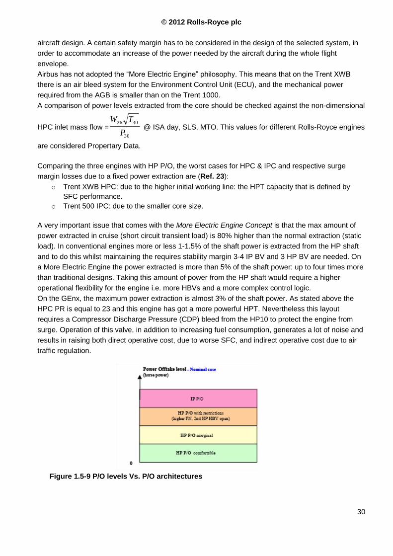
A very important issue that comes with the More Electric Engine Concept is that the max amount of
power extracted in cruise (short circuit transient load) is 80% higher than the normal extraction (static
load). In conventional engines more or less 1-1.5% of the shaft power is extracted from the HP shaft
and to do this whilst maintaining the requires stability margin 3-4 IP BV and 3 HP BV are needed. On
a More Electric Engine the power extracted is more than 5% of the shaft power: up to four times more
than traditional designs. Taking this amount of power from the HP shaft would require a higher
operational flexibility for the engine i.e. more HBVs and a more complex control logic.
On the GEnx, the maximum power extraction is almost 3% of the shaft power. As stated above the
HPC PR is equal to 23 and this engine has got a more powerful HPT. Nevertheless this layout
requires a Compressor Discharge Pressure (CDP) bleed from the HP10 to protect the engine from
surge. Operation of this valve, in addition to increasing fuel consumption, generates a lot of noise and
results in raising both direct operative cost, due to worse SFC, and indirect operative cost due to air
traffic regulation.
Figure 1.5-9 P/O levels Vs. P/O architectures

© 2012 Rolls-Royce plc
31
2 PART TWO - A COMPARISON BETWEEN THE IP AND THE HP P/O SYSTEM
© 2012 Rolls-Royce plc
32
2.1 Engine weight
2.1.1 Differences between IP & HP P/O systems
Without a double-shaft drive on the T1000, the weight penalty due to the power offtake configuration
is only linked to the additional hardware required for the Switched Air System. This additional weight
is “the smaller evil” when comparing power extraction between IP and HP P/O. The additional
hardware required by an HP P/O with a very high level of power extraction, such that required by the
787-9, can be bigger than that associated with the Switched Air System. For instance, an additional
set of bleed valves on both, IP and HP compressor, or bigger core may be required to facilitate high
levels of HP P/O. This configuration would result in additional weight and worse cruise performance.
In principle, there are is direct reason why an IP P/O system should be heavier than an equivalent HP
P/O system. The hardware required to perform the main function (transfer power from the core to the
accessories) is exactly the same.
Considering what stated above the following factors can affect the system weight:
Bearings
Gears
Shaft
Stiffeners
Lubrication system
Differences between these components exist between IP & HP P/O as the torque transmitted to
generate the same amount of power in a system with 25-30% reduced shaft speed is roughly 30-40%
higher. The IP shaft is designed against buckling and the increase in torque due to the P/O system is
quite small so this is not important for the weight.
The actual increase of weight is attributed to the secondary effects of the individual system. A
secondary effect is e.g. the requirement to perform accessory functions (i.e. starting the engine, don‟t
threat the engine stability….) and other assembly features necessary to operate the system (engine
case stiffener, mounting system…).On the Trent 1000 the redesign of the drive train was not
accompanied by a full redesign of the adjacent areas, like e.g. mounting features for SAGB and IGB.
When the clutch was removed on Pack A engines, no other parts of the engine were changed to
recover the full weight penalty. The current design has therefore not been optimized. Knowing the
required dimension of the SAGB without a clutch, a complete redesign of this area could have
resulted in a layout with less interference with the Fan Duct. In the current engine design this feature
has not been changed significantly from the original design.
The IP shaft is designed against buckling and the increase in torque due to the P/O system is quite
small (max 5% shaft torque) so this is not important for the weight.
A short list of operational functions of the P/O system is reported and their impact on the engine
weight discussed.
2.1.2 Extracting power from the core
Increasing the system weight when the general level of power is increased is unavoidable from a
mechanical viewpoint: bigger gear, shafts, bearings and a more capable lubrication system are
required, irrespective of whether the power is extracted from the IP shaft or the HP shaft

© 2012 Rolls-Royce plc
33
2.1.3 Starting the engine
The forecasted increase in weight for the first engine design with the coupling device in the SAGB
ranged between 155 and 255lbs. Most of this mass was due to the clutch, its control system, the
double RDS, gears, bearings and larger casing to house all these components (SAGB sump and fan
air duct).
Because this complex system is no longer necessary, the increase in weight relative to an HP P/O
necessary for the “start the engine” function is zero.
2.1.4 Engine stability
The secondary switched air system is required by the Trent 1000 because of insufficient flows at
ground idle operation. The additional hardware required to switch the Secondary Air System feed
from IP8 to HP3 results in an estimated weight penalty between 55 and 155lbs per engine. The
155lbs weight difference is unlikely because the weight penalty associated with an HP power offtake
system with high power demands have not been taken into account. The indirect effects due to
control components and other necessary elements depend on the requirements of the engine.
Assuming that an HP P/O system (for a three-shaft engine) is able to cope with a 1000Hp extraction,
it would require a complex and heavy stability bleed system (on the GEnx there is also a Compressor
Discharge Pressure valve and, being a two-shaft configuration the GEnx accounted for a more
powerful HP turbine).
The increase in weight necessary to “establish stability margin” on the Trent 1000 has to be
accounted for considering the weigh penalty required to satisfy the same requirement with an HP P/O
system.
2.1.5 Engine weight estimation
An estimation of the weight that could be saved on a redesigned Trent 1000 compared to a Pack A
engine is reported in Ref. 16 redesigning or removing some components of the IP P/O system

© 2012 Rolls-Royce plc
34
2.2 Fuel burn
2.2.1 How the IP P/O system affects the fuel burn
The saving in fuel burn with respect to a 3 shaft engine with HP P/O system can be attributed to:
o IP drive configuration moves the operating points of the engine. The working points of the
compressors have changed, allowing the compressors to rematch (see Par.2.5.2).This has an
impact on the efficiencies and can possibly improve the engine fuel flow at some conditions.
o As described in the operability section, the IP power offtake improves the IPC stability by
dropping off the working line. This gives the opportunity to set up a different handling bleed
valve schedule in order to have less bleed valves open during certain flight segments, such as
hold and descent.
Using the IP P/O system on the B787s allows to reduce the HBV opening time during ground idle or
flight idle descent operations relative to an equivalent engine with HP P/O(see Par.0).This has a
significant effect on the SFC and on the fuel burn. With the original engine design, i.e. with the starting
coupling system, the beneficial effect of the different HBV schedule on the fuel burn is partially
mitigated by the weight increase, as discussed in the previous chapter.
On one of the earliest Trent 1000 engines the idle fuel burn was 40% high relative to the Boeing spec.
This shortfall was mainly due to differences in IP Compressor efficiency, Turbine efficiency, Handling
Bleed Valve schedule and minimum idle setting: excessively optimistic assumptions have been made
during the preliminary study due to the novelty of the engine configuration.
Fuel consumption at idle can be reduced by modifying the gear ratio between the N2 spool and the
generator, through a redesign of the SAGB with range of speeds set to lower N2. It has been
estimated that this would allow for a reduction of the minimum N2 limiter. These modifications have
shown only a little improvement of the block fuel.
2.2.2 Flight conditions
The effects of the IP P/O system on the fuel burn are much more evident for short range missions
where idle, taxi and descent (i.e. those conditions where the IP P/O allow to shut the HBV and the HP
P/O requires air bleed) occupy a larger fraction of the total mission. For a 500nm mission (considered
for Japanese operators), the former studies underlined a 6% benefit on the fuel burn of the RB262-58
(with IP P/O) over the RB262-51 (with HP P/O).
For the baseline aircraft (3000nm mission) the advantage is eroded as the length of time at hold and
descent constitutes a smaller percentage of the total flight cycle and the improvement is
predominantly associated with the ability of the engine to achieve a higher overall pressure ratio.
For instance, with an IP power offtake system, there is no IP handling bleed open at hold whereas,
with a HP offtake system, at least one IP8 bleed valve has to be constantly kept open. This has a
non-negligible impact on the resulting block fuel.
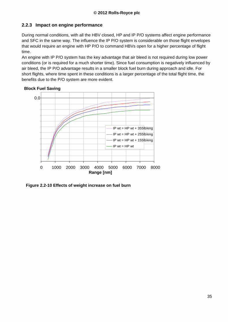
© 2012 Rolls-Royce plc
35
2.2.3 Impact on engine performance
During normal conditions, with all the HBV closed, HP and IP P/O systems affect engine performance
and SFC in the same way. The influence the IP P/O system is considerable on those flight envelopes
that would require an engine with HP P/O to command HBVs open for a higher percentage of flight
time.
An engine with IP P/O system has the key advantage that air bleed is not required during low power
conditions (or is required for a much shorter time). Since fuel consumption is negatively influenced by
air bleed, the IP P/O advantage results in a smaller block fuel burn during approach and idle. For
short flights, where time spent in these conditions is a larger percentage of the total flight time, the
benefits due to the P/O system are more evident.
Figure 2.2-10 Effects of weight increase on fuel burn
0.0
0 1000 2000 3000 4000 5000 6000 7000 8000
Range [nm]
IP wt = HP wt + 355lb/eng
IP wt = HP wt + 255lb/eng
IP wt = HP wt + 155lb/eng
IP wt = HP wt
Block Fuel Saving
© 2012 Rolls-Royce plc
36
2.3 Starting
2.3.1 Introduction to the coupling device and Mark 1 SAGB
The Power Offtake system is also used to crank the engine during the starting procedure. In order to
reduce weight and both engine and system dimensions the core shaft used to drive the accessory
gearbox is also used during the aforementioned procedure. At the beginning of the Trent 1000
programme Rolls-Royce had no experience with the starting of an engine driving only the IP
compressor and test results from a demonstrator engine discouraged the engineers since very long
time was needed to reach a sufficient HP shaft speed (Ref. 5) . The main concern was about how to
mitigate this problem in order to achieve an acceptable starting time with this system. A double
starting system, driving both HP and IP shafts, was introduced in the original Trent 1000 layout. Later,
due to reliability issues and the weight penalty of this solution, the development team attempted to
start the engine driving only the IP shaft. This situation arose when the team faced a clutch failure
which made it impossible to start the engine as intended. The requirements for the power to drive the
IP shaft were unchanged and the same VFSGs were used.
The positive result of this test was a great surprise for all the people involved in the project because
the engine was not designed to start in this configuration. Driving the HP compressor via the IP shaft
is a very inefficient way to obtain the sufficient pressure in the combustion chamber to attempt to light
the combustor. Through the compressors, from the IPC inlet to the HPC outlet, there are many bleed
areas and many sources of losses, thus a big part of the energy transmitted from the IPC to the fluid
is wasted. Because of this, people were surprised in seeing both the shafts reaching the green-light
rotation speed in a relatively short time, comparable with the HP-drive starting time. Rolls Royce
continued the development process of this solution, deleted the clutch and accepted a small shortfall
in starting performance. The engine‟s weight was considerably reduced which eliminated all the
drawbacks linked with the increase in size, relative to an HP P/O system.
2.3.2 Problems with coupling devices
In starting mode each VFSG supplies 300ft-lb of torque to the external gearbox, but when the engine
is running the power is taken from the IP shaft by the IGB. The IGB consists in a couple of conical
gears, that transmit the torque to the SAGB, which reduces the rotational speed by means of a couple
of bevel gears, transmitted through the fan air duct to the transfer gearbox and to the accessory drive
gearbox. In the AGB the torque is used to drive generators, pumps and other accessories. During the
starting procedure the power‟s path is in the opposite direction, with the same hardware used. It was
evident that the problem consisted in designing a light system that could drive two shafts during the
starting procedure, disengage from the HP shaft and, post the cranking procedure, transfer power
only from the IP system.
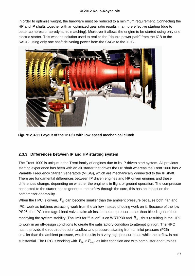
© 2012 Rolls-Royce plc
37
In order to optimize weight, the hardware must be reduced to a minimum requirement. Connecting the
HP and IP shafts together with an optimized gear ratio results in a more effective starting (due to
better compressor aerodynamic matching). Moreover it allows the engine to be started using only one
electric starter. This was the solution used to realize the “double power path” from the IGB to the
SAGB, using only one shaft delivering power from the SAGB to the TGB.
2.3.3 Differences between IP and HP starting system
The Trent 1000 is unique in the Trent family of engines due to its IP driven start system. All previous
starting experience has been with an air starter that drives the HP shaft whereas the Trent 1000 has 2
Variable Frequency Starter Generators (VFSG), which are mechanically connected to the IP shaft.
There are fundamental differences between IP driven engines and HP driven engines and these
differences change, depending on whether the engine is in flight or ground operation. The compressor
connected to the starter has to generate the airflow through the core, this has an impact on the
compressor operability.
When the HPC is driven, 26P can become smaller than the ambient pressure because both, fan and
IPC, work as turbines extracting work from the airflow instead of doing work on it. Because of the low
PS26, the IPC interstage bleed valves take air inside the compressor rather than bleeding it off thus
modifying the system stability. The limit for “fuel on” is on WRTP30 and 30P , thus resulting in the HPC
to work in an off-design conditions to create the satisfactory condition to attempt ignition. The HPC
has to provide the required outlet massflow and pressure, starting from an inlet pressure (P26)
smaller than the ambient pressure, which results in a very high pressure ratio while the airflow is not
substantial. The HPC is working with AmbPP26 as inlet condition and with combustor and turbines
Figure 2.3-11 Layout of the IP P/O with low speed mechanical clutch
© 2012 Rolls-Royce plc
38
acting as downstream blockage. During this procedure, working very far away from its design point,
the compressor is very prone to stall. The goal is to flow as much air as possible to keep the risk of
stall as small as possible. During the initial phase of cranking the HP shaft usually has to be turned
slowly, in order to avoid stall. When the IP system begins to turn and reach a minimum N2, then the
HP spool can be accelerated.
If there is an IP P/O system, the IPC condition during the starting procedure is very different. The inlet
pressure is slightly lower than the ambient pressure and the IPC can rely on the VSVs to improve the
working conditions on the front stages (Trent 1000 has 1 VIGV and 2 VSVs), moreover the IPC is
designed to work over a wider range of “off design” conditions. Consequently the IPC is not in stall
during cranking while in this phase the HPC works as a turbine2 and can run without mechanical
restrictions (i.e. there is no mechanical power extraction from the HP shaft).
During sub-idle running a different off-design condition exists in the last stages of the compressors.
The core is sized for cruise condition during which the pressure increase inside the compressor is
higher, and thus the decrease in air volume is quite substantial. During the starting procedure the PR
is quite low and the axial air speed increases across the compressors, which can lead to a speed
mismatch if the HP spool rotates too slowly. The IP P/O system is more prone to this kind of “off
design” condition because the HP shaft is very slow during the starting procedure. This situation can
easily be handled in an IP P/O system by using bleed valves to reduce the air massflow and its
velocity.
This conditions change at the ignition point, when both compressors begin to work as compressors
(during cranking the HPC works as a turbine) and the turbines begin to produce shaft power. From
this moment the compressors cannot be stalled, however surge could still occur. A minimum HP shaft
speed is required by an HP driven engine to prevent compressor from surge. No lower limit exists for
an IP driven engine, this is because the HPC is never stalled during cranking because it works as a
turbine.
Previous investigations have established that it is possible to start a three shaft engine by spinning
only the IP shaft (Ref. 4) . However, trials on industrial RB211 engines at Ansty (Ref. 6) demonstrated
very slow engine start times. Driving the IP spool by itself, or coupling of the IP and HP spools, during
the starting procedure was not considered a viable method for starting previous Trent engines since it
would have resulted in a too deep redesign of the engine. Previous Trent engines have an HP P/O
system, compressors and turbines are designed to handle different amount of power and have a
different matching range from those required by an IP P/O system. The IPC design PR of the Trent
1000 is quite larger if compared with that of an industrial engine (like that used during the
aforementioned Ansty test). This means that on the T1000 the bigger IPC is able to transfer a much
higher power to the air flow while a smaller HPC represents a weaker downstream blockage during
cranking.
2 Note that to define the effect of the rotors in a certain condition (whether a compressor is making work on the fluid or is
extracting work from it) the only important thing to consider are the flow characteristics; the pressure changes are only a
consequence. The direction of the torque generated by the compressor depends on the blade angles and not on the
pressure ratio.
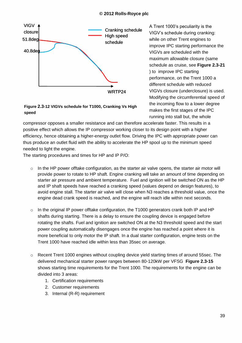
© 2012 Rolls-Royce plc
39
A Trent 1000‟s peculiarity is the
VIGV‟s schedule during cranking:
while on other Trent engines to
improve IPC starting performance the
VIGVs are scheduled with the
maximum allowable closure (same
schedule as cruise, see Figure 2.3-21
) to improve IPC starting
performance, on the Trent 1000 a
different schedule with reduced
VIGVs closure (underclosure) is used.
Modifying the circumferential speed of
the incoming flow to a lower degree
makes the first stages of the IPC
running into stall but, the whole
compressor opposes a smaller resistance and can therefore accelerate faster. This results in a
positive effect which allows the IP compressor working closer to its design point with a higher
efficiency, hence obtaining a higher-energy outlet flow. Driving the IPC with appropriate power can
thus produce an outlet fluid with the ability to accelerate the HP spool up to the minimum speed
needed to light the engine.
The starting procedures and times for HP and IP P/O:
o In the HP power offtake configuration, as the starter air valve opens, the starter air motor will
provide power to rotate to HP shaft. Engine cranking will take an amount of time depending on
starter air pressure and ambient temperature. Fuel and ignition will be switched ON as the HP
and IP shaft speeds have reached a cranking speed (values depend on design features), to
avoid engine stall. The starter air valve will close when N3 reaches a threshold value, once the
engine dead crank speed is reached, and the engine will reach idle within next seconds.
o In the original IP power offtake configuration, the T1000 generators crank both IP and HP
shafts during starting. There is a delay to ensure the coupling device is engaged before
rotating the shafts. Fuel and ignition are switched ON at the N3 threshold speed and the start
power coupling automatically disengages once the engine has reached a point where it is
more beneficial to only motor the IP shaft. In a dual starter configuration, engine tests on the
Trent 1000 have reached idle within less than 35sec on average.
o Recent Trent 1000 engines without coupling device yield starting times of around 55sec. The
delivered mechanical starter power ranges between 80-120kW per VFSG Figure 2.3-15
shows starting time requirements for the Trent 1000. The requirements for the engine can be
divided into 3 areas:
1. Certification requirements
2. Customer requirements
3. Internal (R-R) requirement
WRTP24
VIGV
closure
51.8deg
40.8deg
Cranking schedule
High speed
schedule
Figure 2.3-12 VIGVs schedule for T1000, Cranking Vs High
speed
WRTP24
VIGV
closure
51.8deg
40.8deg
Cranking schedule
High speed
schedule

© 2012 Rolls-Royce plc
40
Theoretically, driving only the IP shaft would lock a normal IPC into stall due to the HPC acting as a
blockage. The Trent 1000‟s IPC capacity is designed larger to achieve a greater stall margin. The
compressor is able to perform a starting procedure with IP cranking, within acceptable starting time,
although requires more time if compared with the coupling device. When the IPC is cranked during
starting and the HP shaft is almost still, part of the HPC is stalled and has a very low efficiency. The
main losses are due to the presence of the combustor and to the absence of sealing air (the
secondary air system is not pressurized yet) which increases bleeds. The time required to overcome
this situation is roughly 30-35secs.
The time to fuel ON and time to idle are nearly divided by two when both the IP and the HP shafts are
cranked during engine start.
Figure 2.3-13 Starting procedure with IP P/O and dual starter (with coupling device).
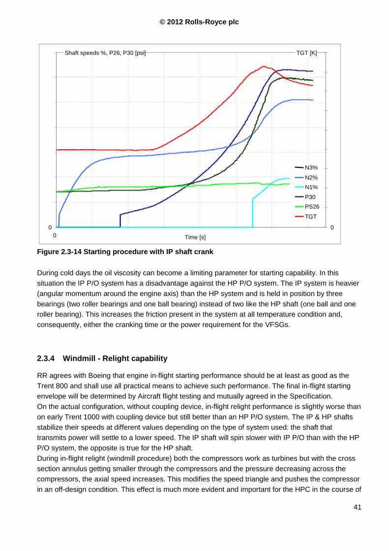
© 2012 Rolls-Royce plc
41
During cold days the oil viscosity can become a limiting parameter for starting capability. In this
situation the IP P/O system has a disadvantage against the HP P/O system. The IP system is heavier
(angular momentum around the engine axis) than the HP system and is held in position by three
bearings (two roller bearings and one ball bearing) instead of two like the HP shaft (one ball and one
roller bearing). This increases the friction present in the system at all temperature condition and,
consequently, either the cranking time or the power requirement for the VFSGs.
2.3.4 Windmill - Relight capability
RR agrees with Boeing that engine in-flight starting performance should be at least as good as the
Trent 800 and shall use all practical means to achieve such performance. The final in-flight starting
envelope will be determined by Aircraft flight testing and mutually agreed in the Specification.
On the actual configuration, without coupling device, in-flight relight performance is slightly worse than
on early Trent 1000 with coupling device but still better than an HP P/O system. The IP & HP shafts
stabilize their speeds at different values depending on the type of system used: the shaft that
transmits power will settle to a lower speed. The IP shaft will spin slower with IP P/O than with the HP
P/O system, the opposite is true for the HP shaft.
During in-flight relight (windmill procedure) both the compressors work as turbines but with the cross
section annulus getting smaller through the compressors and the pressure decreasing across the
compressors, the axial speed increases. This modifies the speed triangle and pushes the compressor
in an off-design condition. This effect is much more evident and important for the HPC in the course of
0
0 35 00 0
N3%
N2%
N1%
P30
PS26
TGT
Shaft speeds %, P26, P30 [psi] TGT [K]
Time [s]
Figure 2.3-14 Starting procedure with IP shaft crank
© 2012 Rolls-Royce plc
42
the relight procedure. The situation with an IP P/O system, slower IPC and faster HPC, is much better
than the situation with the HP P/O. This gives the Trent 1000 an advantage over conventional engines
based on HP P/O systems.
Using a coupling device would improve the performance of the IPC during windmill. The intermediate
pressure compressor works less efficiently as windmill device compared with the HPC, due to a
relatively smaller Mach number seen during this phase.
Connecting the two shafts together would produce a stronger windmill effect compared with the actual
Trent 1000. The consequence would be that less energy is used to drive the AGB and more pressure
is available in the combustor chamber. This would have a direct effect on the relight capability,
especially at high altitude, relaxing a bounding parameter for the combustion chamber.
2.3.5 Hot start
Between ignition and idle, there is the reversion of compressors‟ roles: when thermal power is
available at IP turbine and HP turbine the latter accelerates faster than the former. This is reflected on
compressors‟ behaviours. As this happens the HPC is beginning to work properly as a compressor
and increases his flow demand, acting no longer as blockage for the IPC and removing the risk of stall
in its rear stages.
How does TGT (in terms of engine stations44T , LPT NGVs inlet temperature) affect this process? TGT
in this context is not used to monitor the LPT status but is used as a measure for the thermal state of
the engine when it is shut down. TGT can also be used to introduce in the ECC logic the information
about the hardware temperature since when thermal power is made available to the turbine the HPC
begins working properly; in this condition the engine behaviour changes from cold to hot days. The
Turbine Gas Temperature (TGT) signal can be used in the ECC to account for the Hardware
temperature during the starting procedure. The thermal expansion of shafts, drums, disks, casings etc
can be related with this temperature. These thermal effects change the clearance between the
abradable sealing rings and the compressor‟s blade tip; the phenomenon is called “Casing
Asymmetric Cooling” (CAC). The compressor surge line is very much affected by this situation. CAC
limits the relight capability because increasing locally the tip clearance, it promotes IPC surging. This
phenomenon is common to all engines and is very evident when the engine has been shut for 1-3
hours. Only after about 8 hours the TGT condition depends only on the external (ambient)
temperature.
Based on this, the surge threat can be expressed in terms of max TGT. When the engine has been
shut down only for a short time the TGT is higher than the allowed value, and a venting crank period
prior to relighting of the engine is required in order to cool the relevant engine components down. The
TGT cooling crank increases significantly the starting time during hot day conditions.
With an IP P/O system the HPC compressor is far away from the surge line during cranking
procedure (it is actually working as a turbine and not as a compressor), the limit is then on the IPC.
Being at the cold end of the engine the IPC is much less sensitive to thermal variations. This allows to
increase the max TGT limit for light up, and also incorporates the vent phase into the normal crank
procedure without requiring additional time (Ref. 7) . This results in a benefit every time the engine
has to be shut down and turned on in a short period, like for short-range missions.
© 2012 Rolls-Royce plc
43
Starting time is a major concern for the B787 launch customer (ANA). The Trent 1000 is much less
sensitive to high TGT and reduces the cooling-crank period to save both time and power required to
drive the spool. On Package B engines there is a proposal to raise the maximum fuel-on TGT limit.
2.3.6 Requirements for the P/O system:
1. The drive train has to be designed in order to satisfy the Starting Time Requirements from the
customer. Boeing requirements are reported in Figure 2.3-15 and all other requirements are
listed in Ref. 17
2. AGB/IP shaft gear ratio affects the cranking capability, especially during cold days. This needs
to be considered when designing the P/O drive train.
3. The power transmission system has to facilitate starting power demands.
4. External dimensions of the SAGB shall not affect the fan air duct shape
5. RDS length and bore have to be optimized considering structural issues (power transmitted
and instability) as well as integration issues (interaction with fan duct design, SAGB stiffness
and weight)
6. Consider debris and oil contamination effects on drive train life and required torque during
starting
7. Accommodate for FMECA for starting requirements with one VFSG inoperative, windmill
relight and starting capability with VSV failure
2.3.7 Requirements for stakeholders:
1. A larger IPC with higher PR is required to ensure enough energy is transferred to a sufficient
air mass flow during the starting procedure. This influences the power split between HP and IP
systems
2. IPC must maintain a positive stability margin and PR to start the engine.
3. Consider usage of blisk3 or bling4 for first HPC or last IPC stages to increase available space
in the IGB area and reduce limits on usable gears.
4. Consider pressure levels during cranking in the assessment of air system, oil system,
compressor stability and sealing.
5. Include transient behaviour during cranking and ignition in the assessment of air system, oil
system, compressor stability and sealing.
3 Bladed Disk
4 Integrally bladed ring or bling, see Rolls-Royce Metal Matrix Composite research website.
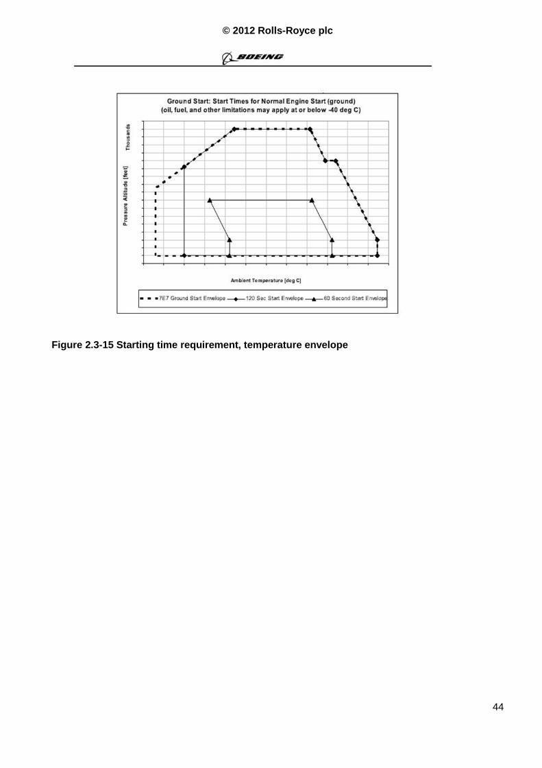
© 2012 Rolls-Royce plc
44
Figure 2.3-15 Starting time requirement, temperature envelope
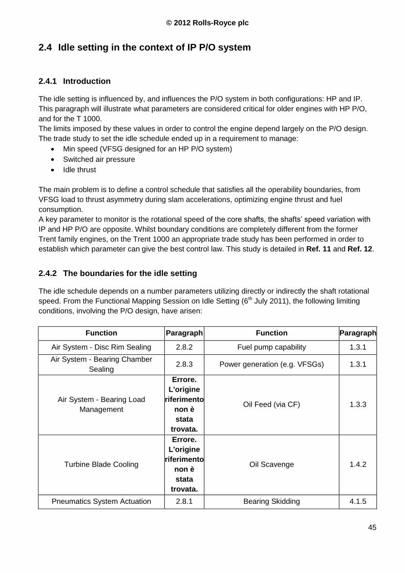
© 2012 Rolls-Royce plc
45
2.4 Idle setting in the context of IP P/O system
2.4.1 Introduction
The idle setting is influenced by, and influences the P/O system in both configurations: HP and IP.
This paragraph will illustrate what parameters are considered critical for older engines with HP P/O,
and for the T 1000.
The limits imposed by these values in order to control the engine depend largely on the P/O design.
The trade study to set the idle schedule ended up in a requirement to manage:
Min speed (VFSG designed for an HP P/O system)
Switched air pressure
Idle thrust
The main problem is to define a control schedule that satisfies all the operability boundaries, from
VFSG load to thrust asymmetry during slam accelerations, optimizing engine thrust and fuel
consumption.
A key parameter to monitor is the rotational speed of the core shafts, the shafts‟ speed variation with
IP and HP P/O are opposite. Whilst boundary conditions are completely different from the former
Trent family engines, on the Trent 1000 an appropriate trade study has been performed in order to
establish which parameter can give the best control law. This study is detailed in Ref. 11 and Ref. 12.
2.4.2 The boundaries for the idle setting
The idle schedule depends on a number parameters utilizing directly or indirectly the shaft rotational
speed. From the Functional Mapping Session on Idle Setting (6th July 2011), the following limiting
conditions, involving the P/O design, have arisen:
Function Paragraph Function Paragraph
Air System - Disc Rim Sealing 2.8.2 Fuel pump capability 1.3.1
Air System - Bearing Chamber
Sealing 2.8.3 Power generation (e.g. VFSGs) 1.3.1
Air System - Bearing Load
Management
Errore.
L'origine
riferimento
non è
stata
trovata.
Oil Feed (via CF) 1.3.3
Turbine Blade Cooling
Errore.
L'origine
riferimento
non è
stata
trovata.
Oil Scavenge 1.4.2
Pneumatics System Actuation 2.8.1 Bearing Skidding 4.1.5
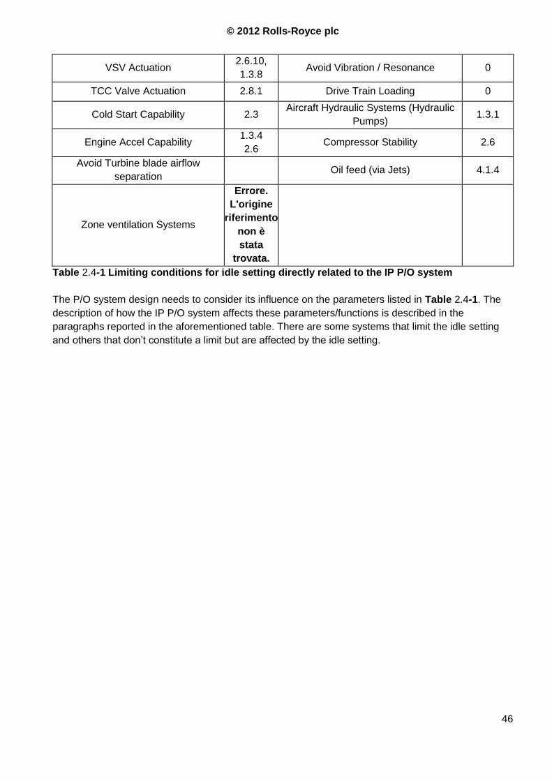
© 2012 Rolls-Royce plc
46
VSV Actuation 2.6.10,
1.3.8 Avoid Vibration / Resonance 0
TCC Valve Actuation 2.8.1 Drive Train Loading 0
Cold Start Capability 2.3 Aircraft Hydraulic Systems (Hydraulic
Pumps) 1.3.1
Engine Accel Capability 1.3.4
2.6 Compressor Stability 2.6
Avoid Turbine blade airflow
separation Oil feed (via Jets) 4.1.4
Zone ventilation Systems
Errore.
L'origine
riferimento
non è
stata
trovata.
Table 2.4-1 Limiting conditions for idle setting directly related to the IP P/O system
The P/O system design needs to consider its influence on the parameters listed in Table 2.4-1. The
description of how the IP P/O system affects these parameters/functions is described in the
paragraphs reported in the aforementioned table. There are some systems that limit the idle setting
and others that don‟t constitute a limit but are affected by the idle setting.
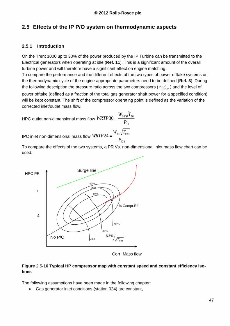
© 2012 Rolls-Royce plc
47
2.5 Effects of the IP P/O system on thermodynamic aspects
2.5.1 Introduction
On the Trent 1000 up to 30% of the power produced by the IP Turbine can be transmitted to the
Electrical generators when operating at idle (Ref. 11). This is a significant amount of the overall
turbine power and will therefore have a significant effect on engine matching.
To compare the performance and the different effects of the two types of power offtake systems on
the thermodynamic cycle of the engine appropriate parameters need to be defined (Ref. 3). During
the following description the pressure ratio across the two compressors ( 2430
PP ) and the level of
power offtake (defined as a fraction of the total gas generator shaft power for a specified condition)
will be kept constant. The shift of the compressor operating point is defined as the variation of the
corrected inlet/outlet mass flow.
HPC outlet non-dimensional mass flow 30
303030
P
TWWRTP
IPC inlet non-dimensional mass flow 024
0242424
P
TWWRTP
To compare the effects of the two systems, a PR Vs. non-dimensional inlet mass flow chart can be
used.
Figure 2.5-16 Typical HP compressor map with constant speed and constant efficiency iso-
lines
The following assumptions have been made in the following chapter:
Gas generator inlet conditions (station 024) are constant,
No P/O
% Compr.Eff.
Surge line HPC PR
Corr. Mass flow
4
7 97%
95%
93%
80%
90%
70%
© 2012 Rolls-Royce plc
48
24
30
PP
is kept constant
Fixed polytrophic exponents for compressor ( 3C ) and turbine ( 5.4T)
Mass flow rate is computed considering the HPT NGVs are choked, .40
404const
P
TW so an
increase in TET produces a decrease of the in core flow proportional to i.e. +5% TET
- =-1.025 -2.5% mass flow
2.5.2 Effects on Core Matching
The working lines of a core driving a free turbine5 are independent from the applied load and are
defined only by the capacity of the turbine. For an aero engine, where the LPT doesn‟t acts as free
turbine but contributes to the compression of the airflow, the LPT load influences the core matching,
but to a small extent (Ref. 36). This is partially due to the fact that the LP system matching
requirements are much less strict than that for the core.
One of the main features of the IP power offtake system is its positive effect on the IPC stability
margin, especially with high levels of extracted power; i.e. the opposite of the HP P/O effect. This is
mainly due to two reasons:
1. The HP and the IP compressor/turbine systems have very different constraints and are
influenced differently by the TET;
2. The HP compressor is aerodynamically more stable than the IPC (smaller speed range,
smaller range of working conditions, directly affected by the combustion chamber)
With an IP P/O system, during low power operation, the unrestricted HPC tries to pull more air
through the core than the mechanically loaded IPC will pass. This situation is aerodynamically much
more stable than the more common situation where the IPC tries to push more air into the HP system
than it can swallow. Indeed, the IPC working line is primarily determined by the flow requirements of
the HPC, thus determining the IPC flow, PR and IPT expansion. The HPC working line on the other
hand is determined by the HPT capacity and , which determine the mass flow.
Considering the characteristics of the airflow at the inlet of the IPC and at the outlet of the HPC the
following considerations apply for our simplified model without bleeds:
The pressure at the IPC inlet and 24
30P
P are given as constants, thus the total pressure at
the HPC outlet (P30) is constant for all the cases in our analysis,
The axial velocity is kept almost constant across the engine, considering inlet end outlet flow
with almost zero swirl speed, which gives a constant static pressure ,
The polytrophic exponent and the pressure ratio are fixed. This also keeps the temperature
ratio across the compressors unchanged,
5 A free turbine, or power turbine, is a turbine that is not used to drive air compression but to generate
mechanical power
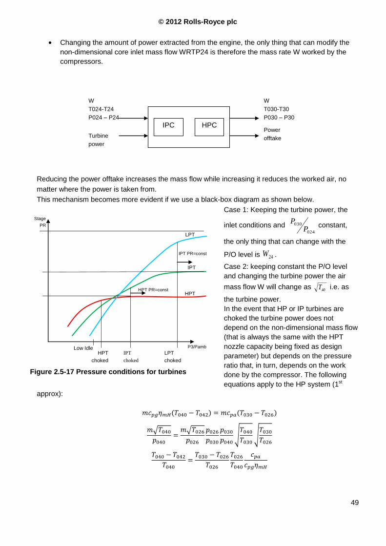
© 2012 Rolls-Royce plc
49
Changing the amount of power extracted from the engine, the only thing that can modify the
non-dimensional core inlet mass flow WRTP24 is therefore the mass rate W worked by the
compressors.
Reducing the power offtake increases the mass flow while increasing it reduces the worked air, no
matter where the power is taken from.
This mechanism becomes more evident if we use a black-box diagram as shown below.
Case 1: Keeping the turbine power, the
inlet conditions and 024
030
PP
constant,
the only thing that can change with the
P/O level is 24W .
Case 2: keeping constant the P/O level
and changing the turbine power the air
mass flow W will change as 40T i.e. as
the turbine power.
In the event that HP or IP turbines are
choked the turbine power does not
depend on the non-dimensional mass flow
(that is always the same with the HPT
nozzle capacity being fixed as design
parameter) but depends on the pressure
ratio that, in turn, depends on the work
done by the compressor. The following
equations apply to the HP system (1st
approx):
W
T024-T24
P024 – P24
IPC HPC
Turbine
power
W
T030-T30
P030 – P30
Power
offtake
HPT PR=const
Stage
PR
P3/Pamb
LPT
IPT
HPT
HPT
choked
IPT
choked
LPT
choked
Figure 2.5-17 Pressure conditions for turbines
Low Idle
IPT PR=const
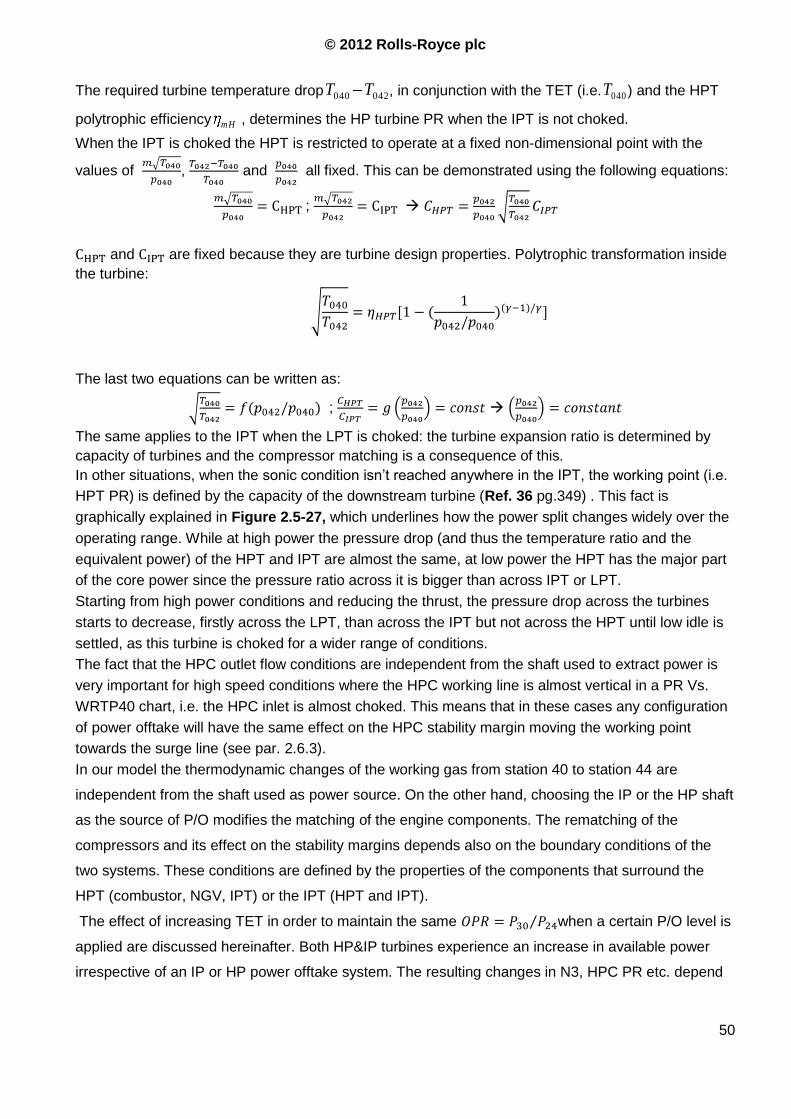
© 2012 Rolls-Royce plc
50
The required turbine temperature drop 042040 TT , in conjunction with the TET (i.e. 040T ) and the HPT
polytrophic efficiency mH , determines the HP turbine PR when the IPT is not choked.
When the IPT is choked the HPT is restricted to operate at a fixed non-dimensional point with the
values of , and all fixed. This can be demonstrated using the following equations:
;
and are fixed because they are turbine design properties. Polytrophic transformation inside
the turbine:
The last two equations can be written as:
;
The same applies to the IPT when the LPT is choked: the turbine expansion ratio is determined by
capacity of turbines and the compressor matching is a consequence of this.
In other situations, when the sonic condition isn‟t reached anywhere in the IPT, the working point (i.e.
HPT PR) is defined by the capacity of the downstream turbine (Ref. 36 pg.349) . This fact is
graphically explained in Figure 2.5-27, which underlines how the power split changes widely over the
operating range. While at high power the pressure drop (and thus the temperature ratio and the
equivalent power) of the HPT and IPT are almost the same, at low power the HPT has the major part
of the core power since the pressure ratio across it is bigger than across IPT or LPT.
Starting from high power conditions and reducing the thrust, the pressure drop across the turbines
starts to decrease, firstly across the LPT, than across the IPT but not across the HPT until low idle is
settled, as this turbine is choked for a wider range of conditions.
The fact that the HPC outlet flow conditions are independent from the shaft used to extract power is
very important for high speed conditions where the HPC working line is almost vertical in a PR Vs.
WRTP40 chart, i.e. the HPC inlet is almost choked. This means that in these cases any configuration
of power offtake will have the same effect on the HPC stability margin moving the working point
towards the surge line (see par. 2.6.3).
In our model the thermodynamic changes of the working gas from station 40 to station 44 are
independent from the shaft used as power source. On the other hand, choosing the IP or the HP shaft
as the source of P/O modifies the matching of the engine components. The rematching of the
compressors and its effect on the stability margins depends also on the boundary conditions of the
two systems. These conditions are defined by the properties of the components that surround the
HPT (combustor, NGV, IPT) or the IPT (HPT and IPT).
The effect of increasing TET in order to maintain the same when a certain P/O level is
applied are discussed hereinafter. Both HP&IP turbines experience an increase in available power
irrespective of an IP or HP power offtake system. The resulting changes in N3, HPC PR etc. depend

© 2012 Rolls-Royce plc
51
on the power required by the components mounted on the HP shaft (i.e. only HPC or HPC+P/O). On
the other hand the IP turbine power does not depend on the power that is extracted from the gas path
by the HPT, for a given TET. An increase in , obtained by burning more fuel, increases the power
available at the HPT and raises the HPC WL. The IPT “sees” the downstream flow conditions, i.e.
power from combustion minus the power extracted by the HPT. This happens because the HPT
always extracts part of the extra power from the gas flow. Since the power split across the turbines
depends on theirs capacities (which are fixed), when increases (e.g. resulting in +Y% HPT
power), roughly the same % power increase applies to the IP and LP turbines. The core turbine power
has to be increased by the amount needed to deal with the P/O level. The compression system then
re-balances to reach a new matching condition. For example with an HP power offtake the HPC
power falls and the IPC power rises. In Figure 2.5-28 is reported a graphical representation of the
power split variation in the core when either, IP or HP P/O system is used. The opposite happens with
IP power. Which is better for SFC depends on the efficiencies of the components at the new operating
points and on the power in those spools. It does not depend on the initial power levels of the turbines.
Setting in order to provide the additional power to the desired turbine, i.e. that mounted on the
P/O shaft, modifies the power of the other turbines and compressors depending on which shaft is
used for P/O.
This is only a rough, quantitative example but gives the idea of the different boundaries that apply on
IP and HP systems.
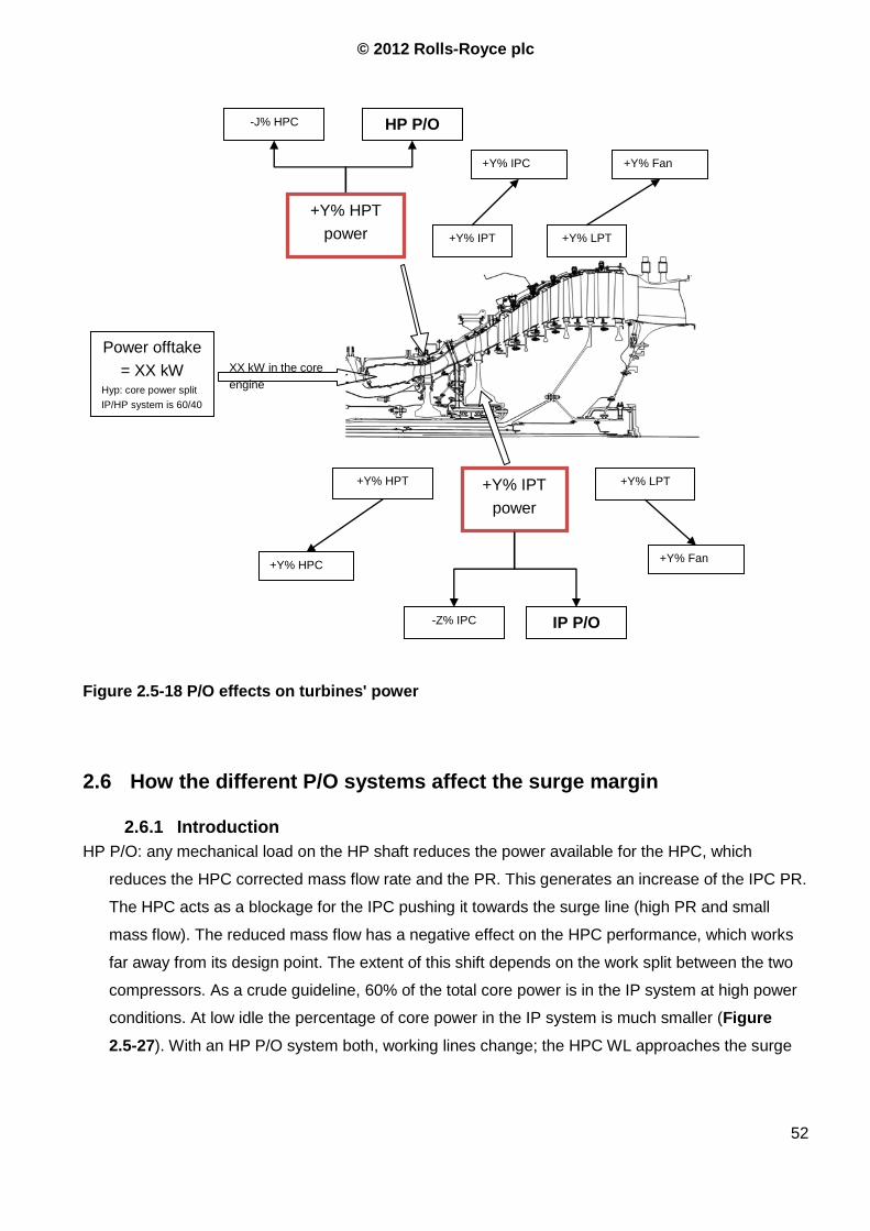
© 2012 Rolls-Royce plc
52
2.6 How the different P/O systems affect the surge margin
2.6.1 Introduction
HP P/O: any mechanical load on the HP shaft reduces the power available for the HPC, which
reduces the HPC corrected mass flow rate and the PR. This generates an increase of the IPC PR.
The HPC acts as a blockage for the IPC pushing it towards the surge line (high PR and small
mass flow). The reduced mass flow has a negative effect on the HPC performance, which works
far away from its design point. The extent of this shift depends on the work split between the two
compressors. As a crude guideline, 60% of the total core power is in the IP system at high power
conditions. At low idle the percentage of core power in the IP system is much smaller (Figure
2.5-27). With an HP P/O system both, working lines change; the HPC WL approaches the surge
Power offtake
= XX kW Hyp: core power split
IP/HP system is 60/40
XX kW in the core
engine
+Y% HPT
+Y% HPC
HP P/O
+Y% IPT
power
-Z% IPC
+Y% LPT
+Y% HPT
power +Y% IPT +Y% LPT
IP P/O
+Y% Fan
-J% HPC
+Y% Fan +Y% IPC
Figure 2.5-18 P/O effects on turbines' power
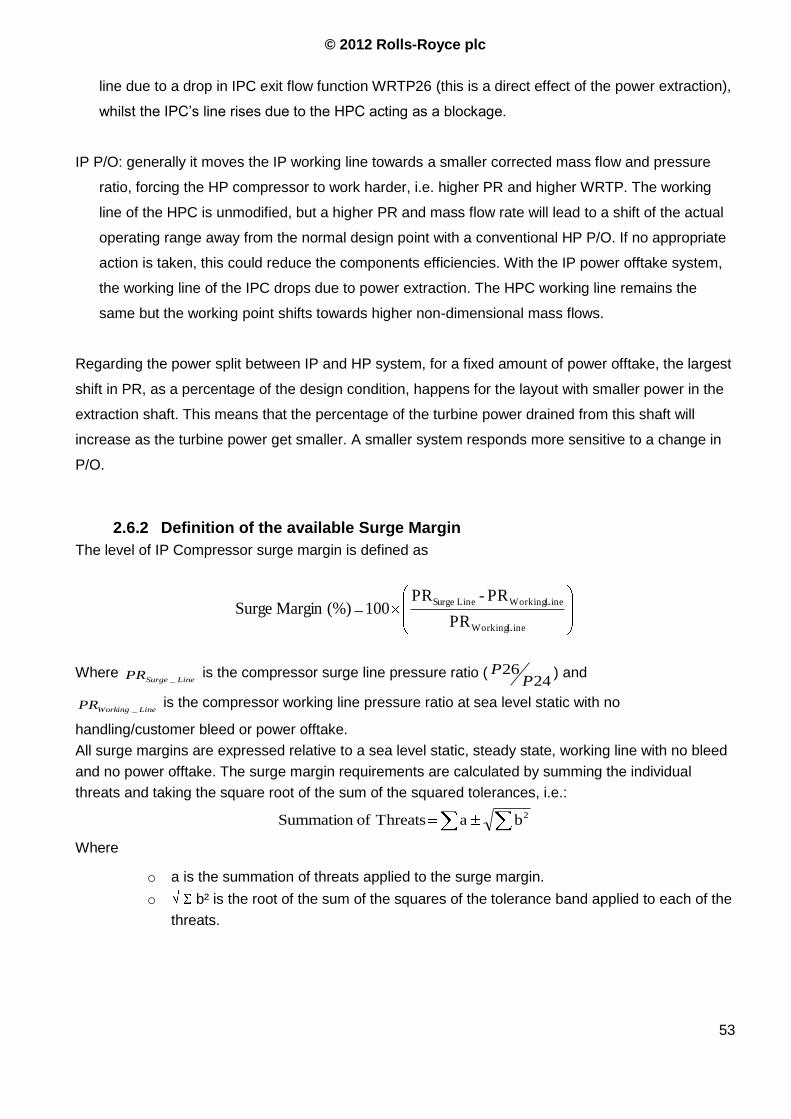
© 2012 Rolls-Royce plc
53
line due to a drop in IPC exit flow function WRTP26 (this is a direct effect of the power extraction),
whilst the IPC‟s line rises due to the HPC acting as a blockage.
IP P/O: generally it moves the IP working line towards a smaller corrected mass flow and pressure
ratio, forcing the HP compressor to work harder, i.e. higher PR and higher WRTP. The working
line of the HPC is unmodified, but a higher PR and mass flow rate will lead to a shift of the actual
operating range away from the normal design point with a conventional HP P/O. If no appropriate
action is taken, this could reduce the components efficiencies. With the IP power offtake system,
the working line of the IPC drops due to power extraction. The HPC working line remains the
same but the working point shifts towards higher non-dimensional mass flows.
Regarding the power split between IP and HP system, for a fixed amount of power offtake, the largest
shift in PR, as a percentage of the design condition, happens for the layout with smaller power in the
extraction shaft. This means that the percentage of the turbine power drained from this shaft will
increase as the turbine power get smaller. A smaller system responds more sensitive to a change in
P/O.
2.6.2 Definition of the available Surge Margin
The level of IP Compressor surge margin is defined as
Line Working
Line WorkingLine Surge
PR
PR - PR 100 (%)Margin Surge
Where LineSurgePR _
is the compressor surge line pressure ratio (24
26P
P ) and
LineWorkingPR _ is the compressor working line pressure ratio at sea level static with no
handling/customer bleed or power offtake.
All surge margins are expressed relative to a sea level static, steady state, working line with no bleed
and no power offtake. The surge margin requirements are calculated by summing the individual
threats and taking the square root of the sum of the squared tolerances, i.e.:
2b a Threats ofSummation
Where
o a is the summation of threats applied to the surge margin.
o b² is the root of the sum of the squares of the tolerance band applied to each of the
threats.
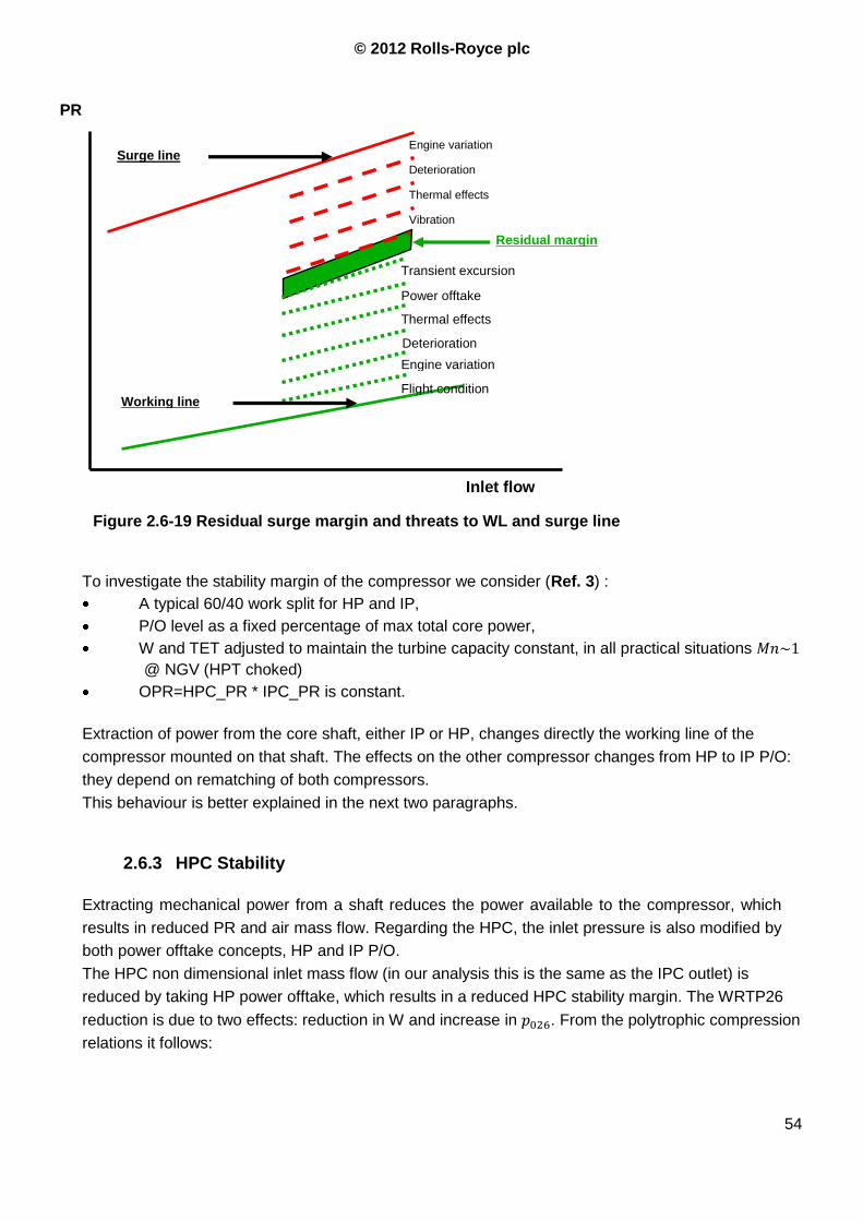
© 2012 Rolls-Royce plc
54
To investigate the stability margin of the compressor we consider (Ref. 3) :
A typical 60/40 work split for HP and IP,
P/O level as a fixed percentage of max total core power,
W and TET adjusted to maintain the turbine capacity constant, in all practical situations
@ NGV (HPT choked)
OPR=HPC_PR * IPC_PR is constant.
Extraction of power from the core shaft, either IP or HP, changes directly the working line of the
compressor mounted on that shaft. The effects on the other compressor changes from HP to IP P/O:
they depend on rematching of both compressors.
This behaviour is better explained in the next two paragraphs.
2.6.3 HPC Stability
Extracting mechanical power from a shaft reduces the power available to the compressor, which
results in reduced PR and air mass flow. Regarding the HPC, the inlet pressure is also modified by
both power offtake concepts, HP and IP P/O.
The HPC non dimensional inlet mass flow (in our analysis this is the same as the IPC outlet) is
reduced by taking HP power offtake, which results in a reduced HPC stability margin. The WRTP26
reduction is due to two effects: reduction in W and increase in . From the polytrophic compression
relations it follows:
Figure 2.6-19 Residual surge margin and threats to WL and surge line
Engine variation Surge line
Deterioration
Thermal effects
Residual margin
Vibration
Transient excursion
Power offtake
Thermal effects
Deterioration
Engine variation
Flight condition Working line
Inlet flow
PR
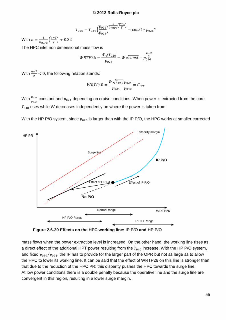
© 2012 Rolls-Royce plc
55
With
The HPC inlet non dimensional mass flow is
With , the following relation stands:
With constant and depending on cruise conditions. When power is extracted from the core
rises while W decreases independently on where the power is taken from.
With the HP P/O system, since is larger than with the IP P/O, the HPC works at smaller corrected
mass flows when the power extraction level is increased. On the other hand, the working line rises as
a direct effect of the additional HPT power resulting from the increase. With the HP P/O system,
and fixed , the IP has to provide for the larger part of the OPR but not as large as to allow
the HPC to lower its working line. It can be said that the effect of WRTP26 on this line is stronger than
that due to the reduction of the HPC PR: this disparity pushes the HPC towards the surge line.
At low power conditions there is a double penalty because the operative line and the surge line are
convergent in this region, resulting in a lower surge margin.
No P/O
Figure 2.6-20 Effects on the HPC working line: IP P/O and HP P/O
Surge line
IP P/O
WRTP26
IP P/O Range HP P/O Range
Normal range
Effect of HP P/O
HP PR Stability margin
Effect of IP P/O
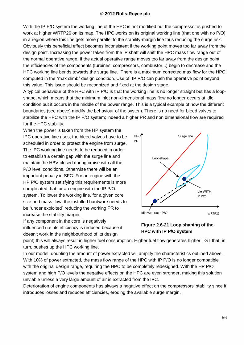
© 2012 Rolls-Royce plc
56
With the IP P/O system the working line of the HPC is not modified but the compressor is pushed to
work at higher WRTP26 on its map. The HPC works on its original working line (that one with no P/O)
in a region where this line gets more parallel to the stability-margin line thus reducing the surge risk.
Obviously this beneficial effect becomes inconsistent if the working point moves too far away from the
design point. Increasing the power taken from the IP shaft will shift the HPC mass flow range out of
the normal operative range. If the actual operative range moves too far away from the design point
the efficiencies of the components (turbines, compressors, combustor...) begin to decrease and the
HPC working line bends towards the surge line. There is a maximum corrected max flow for the HPC
computed in the “max climb” design condition. Use of IP P/O can push the operative point beyond
this value. This issue should be recognized and fixed at the design stage.
A typical behaviour of the HPC with IP P/O is that the working line is no longer straight but has a loop-
shape, which means that the minimum inlet non-dimensional mass flow no longer occurs at idle
condition but it occurs in the middle of the power range. This is a typical example of how the different
boundaries (see above) modify the behaviour of the system. There is no need for bleed valves to
stabilize the HPC with the IP P/O system; indeed a higher PR and non dimensional flow are required
for the HPC stability.
When the power is taken from the HP system the
IPC operative line rises, the bleed valves have to be
scheduled in order to protect the engine from surge.
The IPC working line needs to be reduced in order
to establish a certain gap with the surge line and
maintain the HBV closed during cruise with all the
P/O level conditions. Otherwise there will be an
important penalty in SFC. For an engine with the
HP P/O system satisfying this requirements is more
complicated that for an engine with the IP P/O
system. To lower the working line, for a given core
size and mass flow, the installed hardware needs to
be “under exploited” reducing the working PR to
increase the stability margin.
If any component in the core is negatively
influenced (i.e. its efficiency is reduced because it
doesn‟t work in the neighbourhood of its design
point) this will always result in higher fuel consumption. Higher fuel flow generates higher TGT that, in
turn, pushes up the HPC working line.
In our model, doubling the amount of power extracted will amplify the characteristics outlined above.
With 10% of power extracted, the mass flow range of the HPC with IP P/O is no longer compatible
with the original design range, requiring the HPC to be completely redesigned. With the HP P/O
system and high P/O levels the negative effects on the HPC are even stronger, making this solution
unviable unless a very large amount of air is extracted from the IPC.
Deterioration of engine components has always a negative effect on the compressors‟ stability since it
introduces losses and reduces efficiencies, eroding the available surge margin.
Idle WITHOUT P/O
Idle WITH
IP P/O
Loopshape
HPC
PR
WRTP26
Surge line
Figure 2.6-21 Loop shaping of the
HPC with IP P/O system
© 2012 Rolls-Royce plc
57
2.6.4 P/O effects on HPC worst case assessment
Unlike the IPC, the HP compressor stability stack-up with either HP or IP P/O system should
always include the effect of high power offtake when accounting for the threats applied to the
working line. The worst maneuvers in the above idle engine operating range have been identified
using experience of the previous Trent engines. The worst case stability for slam acceleration is
based on transient engine modelling and verified by test.
After accounting for the threats, the XWB HP compressor residual surge margin has been assessed
at each of these critical points for both IP and HP power offtake configurations. The final HPC stack-
ups with IP and HP power offtake from the Trent 1700 trade study using the respective handling bleed
valve schedules are reported in Ref. 21. In fact, as the HPC does not operate at the same point on its
map depending on IP or HP power offtake, the bleed valve schedules must be set to accommodate
for this difference and compensate for the threats. The shortfalls associated with increased bleed
requirement for the HP P/O system were discussed in a previous paragraph. It can be said that the
HP compressor efficiency is likely to vary quite a lot from IP to HP offtake. This difference cannot be
captured in the stack-ups. The IP offtake configuration gives better HPC stability than the HP offtake
option when the same bleed valve schedule is used. For further information regarding HPC stability
and stack-ups see Ref. 21.
2.6.5 IPC stability
The boundary conditions for the IP system are slightly different since between the compressor and
the turbine there is not only the combustor but also the HP system. This system can represent a
blockage or can promote the flow through the IPC whether the HPC required flow is smaller or
bigger than that delivered by the IPC. Being in one situation or another depends also on the P/O
system layout.
With an HP P/O system the IPC working line changes unlike the HPC WL with the IP P/O. When
power is extracted from the HP shaft, the specific power of the turbines is increased as a result of
the increase in turbine inlet temperature temperature. This means that the IPC specific power also
raises, i.e. pressure ratio at a flow increases. The intermediate pressure compressor tries to
accelerate in order to deliver a higher pressure ratio. If the compressor is operated on its standard
working line, this results in a larger WRTP24. The HPT cannot swallow all the air that the IPC tries
to compress since its capacity is fixed:
is fixed because it is the HPT capacity, is fixed for hypothesis and is almost
constant because it depends only on the combustor losses. Since has to be increased in order
do deal with the power offtake, the final result is that decreases. This blockage pushes the IPC
to work at lower WRTP24 with an increased PR, i.e. with reduced stall margin.
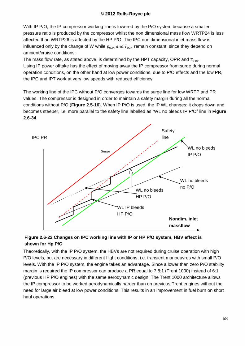
© 2012 Rolls-Royce plc
58
With IP P/O, the IP compressor working line is lowered by the P/O system because a smaller
pressure ratio is produced by the compressor whilst the non dimensional mass flow WRTP24 is less
affected than WRTP26 is affected by the HP P/O. The IPC non dimensional inlet mass flow is
influenced only by the change of W while remain constant, since they depend on
ambient/cruise conditions.
The mass flow rate, as stated above, is determined by the HPT capacity, OPR and .
Using IP power offtake has the effect of moving away the IP compressor from surge during normal
operation conditions, on the other hand at low power conditions, due to P/O effects and the low PR,
the IPC and IPT work at very low speeds with reduced efficiency.
The working line of the IPC without P/O converges towards the surge line for low WRTP and PR
values. The compressor is designed in order to maintain a safety margin during all the normal
conditions without P/O (Figure 2.5-16). When IP P/O is used, the IP WL changes: it drops down and
becomes steeper, i.e. more parallel to the safety line labelled as “WL no bleeds IP P/O” line in Figure
2.6-34.
Theoretically, with the IP P/O system, the HBVs are not required during cruise operation with high
P/O levels, but are necessary in different flight conditions, i.e. transient manoeuvres with small P/O
levels. With the IP P/O system, the engine takes an advantage. Since a lower than zero P/O stability
margin is required the IP compressor can produce a PR equal to 7.8:1 (Trent 1000) instead of 6:1
(previous HP P/O engines) with the same aerodynamic design. The Trent 1000 architecture allows
the IP compressor to be worked aerodynamically harder than on previous Trent engines without the
need for large air bleed at low power conditions. This results in an improvement in fuel burn on short
haul operations.
Surge
WL no bleeds
HP P/O
Safety
line
WL IP bleeds
HP P/O Nondim. inlet
massflow
WL no bleeds
no P/O
IPC PR
WL no bleeds
IP P/O
Figure 2.6-22 Changes on IPC working line with IP or HP P/O system, HBV effect is
shown for Hp P/O
© 2012 Rolls-Royce plc
59
Taking power from the IP shaft, as stated above, modifies in a convenient way the IPC working line
since it increases its steepness. Consequently the available surge margin increases as the extraction
level gets higher. This allows for a reduced base surge margin and it is possible to obtain a larger
pressure ratio at high power settings. In this way it is possible to exploit the hardware at its best,
reducing the component weight at a given performance.
2.6.6 P/O effects on IPC worst case assesment
Data removed
2.6.7 LP power offtake
The LP P/O provides some interesting features. Some of these are:
It doesn‟t change the core matching,
LPT is very efficient, best place to take power off, it is “designed” right for this purpose,
Possibility of using the fan as windmill generator to obtain emergency power for the aircraft,
The LP P/O concept has also a series of drawbacks for using it on a civil aero engine:
The LP shaft has a very wide speed range (@ idle 20% of design N1),currently not compliant with
VFSG speed range,
High power offtake levels at low idle are problematic. In order to maintain a min N1 speed more
fuel must be burned which also increases the HP and IP speed resulting in a higher thrust. The
core needs to be oversized to cope with this situation.
Cannot be used to start the engine. Need for an additional mechanical drive/starter.
2.6.8 Core size
The design of new engines is going towards smaller core sizes optimized for cruise conditions in
order to improve efficiency and reduce engine weight. A conventional HP P/O system would struggle
to deliver the amount of power required by the Boeing 787. A consequence of high P/O levels would
be a continuous increase of the core‟s dimensions thus leading to a heavier engine. This will
considerably worsen the cruise SFC. On the RB262-51 (former name of the Trent 1000, preliminary
study, configuration 51), adopting a HP P/O system, the high power demand was one of the
controlling parameters for the minimum achievable engine core size. This situation is further
aggravated by the requirement to achieve low thrust during the descent phase of the flight.
This problem was solved on the Trent 1000 by using the IP P/O system.
Figure Errore. Per applicare Heading 2 al testo da visualizzare in questo punto, utilizzare la scheda
Home.-23 Effects of the switched air system on the HPC and IPC stability margin
© 2012 Rolls-Royce plc
60
2.6.9 Operability / HBV control
To rematch the core and control the engine stability, two systems are used on the Trent 1000:
Handling Bleed Valves and Variable Stator Vanes. The main difference between T1000 and other
engines is how and when these systems are used. The HBVs are used on both compressors; on the
other hand the VSVs are used only on the IPC. With an IP P/O system this allows to use the angle of
the VSVs as an additional parameter to control the compressor mounted on the shaft used for power
extraction.
The main differences between an IP P/O and HP P/O, with regards to the HBV operation, are:
o With an HP power offtake configuration, the first IP8 handling bleed valve must open earlier
than with an IP P/O for both steady state and transient schedules, to accommodate for the
higher threats due to power offtake. This will cause fuel burn penalties as the IP handling
bleed valve will be opened more often at certain flight conditions like taxing and descents
(report PTR127002)
o The HP3 steady state handling bleed valve schedule has been kept identical for both offtake
configurations. Although reduced with HP power offtake, the residual surge margin remains
positive at all stack-up cases.
o Transiently, the HP handling bleed valve HP3.1 will be closing at a lower speed with an HP
offtake configuration to accommodate for the higher power offtake threats. This is due to the
working line excursion, which operates at a lower power setting, and to the nature of the surge
line, which drops as bleed valves open.
From the performance point of view the big work is on schedule optimization, taking into account
the requirements on bleed stations and flow rates that, as on the Trent 1000, could be influenced
by the P/O strategy. To do this, precise information about how the IP P/O system works has to be
collected from flight tests over the whole flight envelope.
2.6.10 Operability / VSV control
The control of the VSV incidence angle is required to:
obtain optimum SFC,
relax the N2 speed margin,
improve low idle performance,
improve IPC surge margin
improve IPC off design performance
reduce IPC noise.
Other characteristics that are influenced by the VSV schedule are: VSV actuator load, air system
behaviour and blade/vane stress which all need to remain within acceptable limits. Extracting power
from the IP shaft and using it to start the engine modifies the control law as well as the VSV schedule.
IP P/O drops the working line on the IP compressor, as the HPC is driving more freely (no more
blockage) and improves surge margin at all flows. On the other side, the HPC reduces the operating
range (HPC works at higher flows) improving low power surge margin.
The operational requirements for the Handling Bleed Valves are:
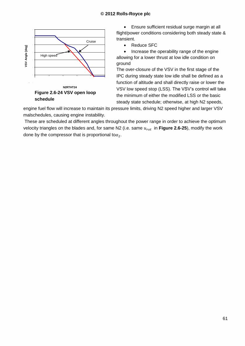
© 2012 Rolls-Royce plc
61
Ensure sufficient residual surge margin at all
flight/power conditions considering both steady state &
transient.
Reduce SFC
Increase the operability range of the engine
allowing for a lower thrust at low idle condition on
ground
The over-closure of the VSV in the first stage of the
IPC during steady state low idle shall be defined as a
function of altitude and shall directly raise or lower the
VSV low speed stop (LSS). The VSV‟s control will take
the minimum of either the modified LSS or the basic
steady state schedule; otherwise, at high N2 speeds,
engine fuel flow will increase to maintain its pressure limits, driving N2 speed higher and larger VSV
malschedules, causing engine instability.
These are scheduled at different angles throughout the power range in order to achieve the optimum
velocity triangles on the blades and, for same N2 (i.e. same in Figure 2.6-25), modify the work
done by the compressor that is proportional to .
VSV Schedule
-10
0
10
20
30
40
50
60
50 60 70 80 90 100
N2RTHT24
VS
V A
ng
le [
deg
]
VSV Schedule
Figure 2.6-24 VSV open loop
schedule
High speed

Cruise
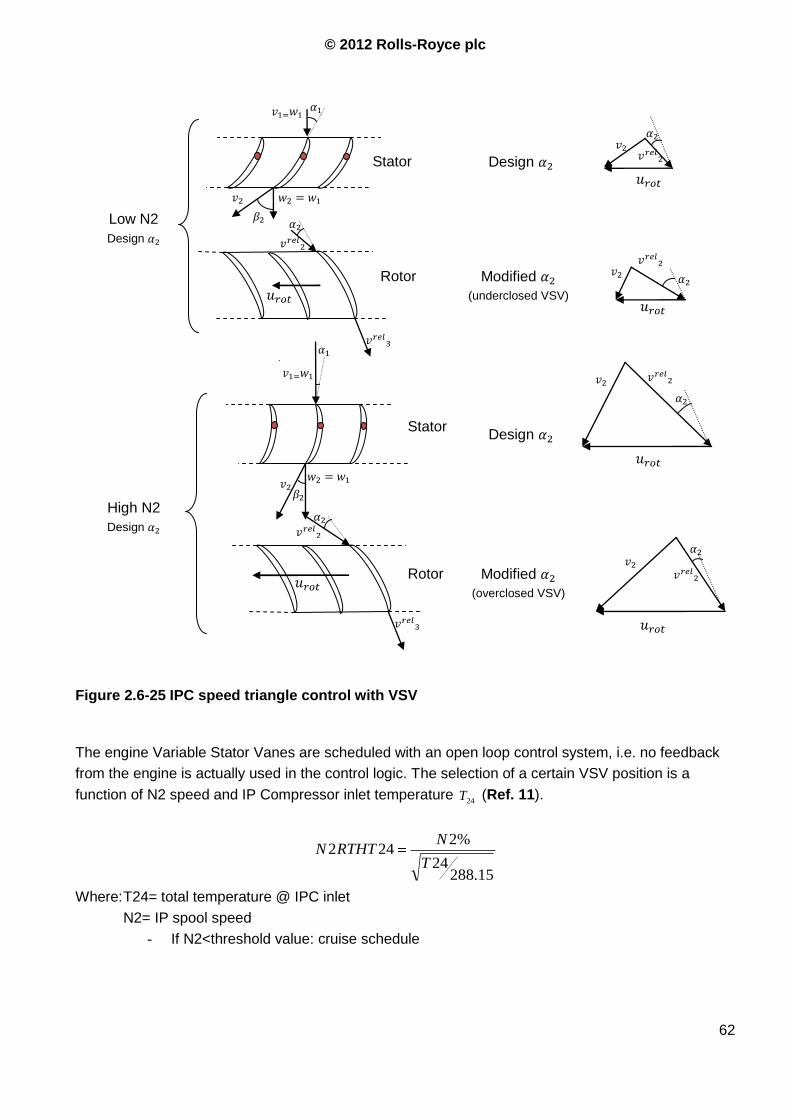
© 2012 Rolls-Royce plc
62
The engine Variable Stator Vanes are scheduled with an open loop control system, i.e. no feedback
from the engine is actually used in the control logic. The selection of a certain VSV position is a
function of N2 speed and IP Compressor inlet temperature 24T (Ref. 11).
15.28824
%2242
T
NRTHTN
Where: T24= total temperature @ IPC inlet
N2= IP spool speed
- If N2<threshold value: cruise schedule
Figure 2.6-25 IPC speed triangle control with VSV
Low N2
Design
High N2
Design
Stator
Rotor
Rotor
Stator
Modified
(overclosed VSV)
Design
Design
Modified
(underclosed VSV)

© 2012 Rolls-Royce plc
63
- If N2>threshold value: high-speed
schedule
- If between: interpolation
The optimal VSV schedule is chosen as a compromise
between compressor efficiency and available surge
margin. To improve the efficiency of this system and
optimize idle fuel consumption the main problem of the
open-loop VSV control is overcome. As sentenced
above, the schedule has to be chosen as a compromise,
considering the minimum required margin for the sudden
application of the highest possible load. Because of this
the compressor cannot work in a high-efficiency point. In
particular, for idle operation the VSVs are scheduled
predominantly to maximize surge margin (same applied
load subtracts more stability margin because of the
higher %turbine power value) hence resulting in severe
efficiency penalties and low levels of compressor outlet
pressure.
The most desirable idle operating point is one where the
engine is simultaneously running at the minimum compressor outlet pressure AND at the minimum
speed. The VSV closed loop control scheme basically attempts to accomplish this by using the
existing fuel control loops which are part of the Control System. The compressor VSVs are used as a
second variable to modulate the relationship between pressure rise and speed. It is now possible to
use a reference working line and, for a givenambP , P24 and T24, define the minimum P26/P24 and
N2RTHT24.
The control system detects the actual operating point and, knowing the reference working line,
modifies the VSV LSS position in order to minimize the distance between the current operating point
and the reference working line.
The overclosure of VSV‟s allows increasing the IP shaft speed range (as Redline/idle speed). This
has demonstrated a satisfactory low idle thrust. This system is however constrained by the
accessories‟ speed range.
The HP P/O system doesn‟t need to deal with this problem because the higher T40 required to
facilitate the P/O is directly used by the HPT. Delivering the required power in an IP P/O system, the
increase in fluid energy (higher T40) is not felt only by the IPT but also by the HPT. This results in an
increase in generated thrust. See also Par.2.5.2.
2.6.11 Cruise conditions
The VSV schedule during cruise condition is not directly affected by the power offtake system but is
influenced by the engine idle control logic that is different from those on the previous Trent engines.
For a typical flight descent profile the engine operates at high idle with relatively low corrected IP
speeds (engine running to shaft speed control). However, when the engine is controlled to one of its
Engine
Pamb
Calculate minimum required compressor corrected outlet
pressure and minimum required compressor corrected speed
Calculate reference compressor operating line
Engine
Variable Stator Vane actuator
P20 T20
Compare measured operating point with reference working line
Compressor speed
Compressor outlet pressure
© 2012 Rolls-Royce plc
64
pressure limits, due to the aircraft operating at high altitude, low Mach number and high IP offtake,
this will push the engine steady state operating points to higher corrected N2 speeds. It is important
that the VSV‟s are constrained to the Minimum of either the nominal steady state VSV schedule or the
Overclosed LSS. Otherwise, if the VSV‟s remain on the overclosed LSS, the engine control would
continue to raise fuel flow in an attempt to maintain its pressure limit, resulting in high values of N2
speed and ever increasing levels of VSV malschedule.
2.6.12 Effect of P/O on core size for increased BPR
As seen in previous chapters the IP P/O system modifies the IP working line, making it steeper
(almost parallel to the surge line) and reduce the PR when power is extracted from the core. Taking
power from the IP shaft allows the IPC working line to be raised to higher PR in zero-load conditions
since in normal operation the stability margin will increase. This results in a key advantage for a
turbofan with an high bypass ratio (HBPR). Indeed, maintaining the same core size and increasing the
fan diameter or reducing the core dimension for the same fan size (i.e. increasing the BPR to obtain a
higher propulsion efficiency) results in a higher bypass/core mass flow ratio and a lower pressure ratio
across the fan. This is clear if, considering the same core (i.e. same LPT power), the flow rate worked
by the fan is increased. The HBPR philosophy consists in accelerating a bigger amount of air to a
lower speed, this is achieved by increasing the bypass ratio and obtaining a smaller PR across the
fan (this means a lower 125P and 125T with risk of ice on the ESS, see Ref. 24). Thus, in order to
increase the BPR the contribution of the fan to the OPR is reduced and this loss in pressure has to be
recovered in the core engine in order to maintain a high efficiency of the thermal cycle.
The HPC is already working at its best and on modern engines there is no appreciable margin for
improvement in that direction. The IP P/O system allows recovery of the loss in the fan PR within the
IPC, resulting in a more efficient and lighter fan (20 fan blades are sufficient to provide the required
PR) without affecting the core performance. As stated in the IPC stability paragraph, with IP P/O the
engine takes an advantage by a higher compressor PR with the same aerodynamic design and same
dimensions. Actually a different PR means different loads that require a modified structure to
withstand the cycles.
This aspect is very important for future engines: airlines and aircraft manufacturers are given lower
limits for the operative cost and the environmental impact of their airplanes. The general trend is to
reduce the cruise speed in order to diminish the drag on the engine. Increasing the engine efficiency
by using higher bypass ratios is compatible with the reduced cruise speed. Owning the know-how and
the experience in the IP P/O system and be capable of delivering an effective solution in a short time
can give R-R an advantage over other competitors.
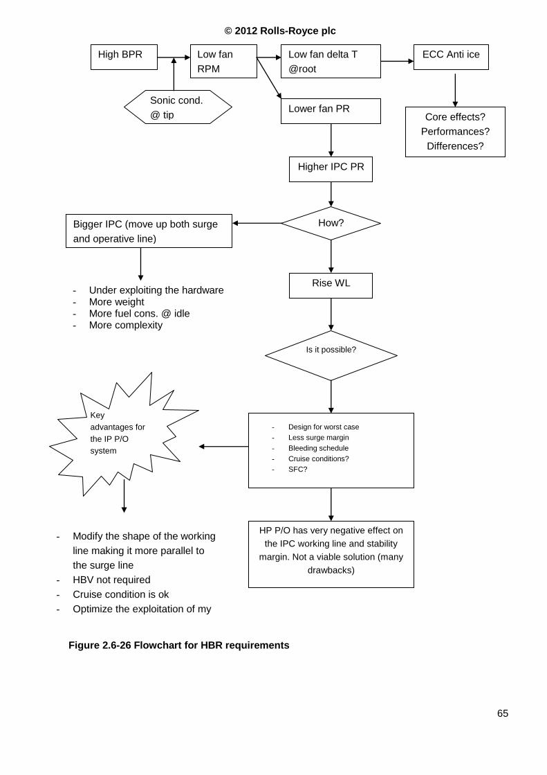
© 2012 Rolls-Royce plc
65
High BPR Low fan
RPM
Low fan delta T
@root
Bigger IPC (move up both surge
and operative line)
- Under exploiting the hardware - More weight - More fuel cons. @ idle - More complexity
Is it possible?
- Design for worst case
- Less surge margin
- Bleeding schedule
- Cruise conditions?
- SFC?
HP P/O has very negative effect on
the IPC working line and stability
margin. Not a viable solution (many
drawbacks)
Key
advantages for
the IP P/O
system
- Modify the shape of the working
line making it more parallel to
the surge line
- HBV not required
- Cruise condition is ok
- Optimize the exploitation of my
hardware
Sonic cond.
@ tip Lower fan PR
ECC Anti ice
Core effects?
Performances?
Differences?
Higher IPC PR
How?
Rise WL
Figure 2.6-26 Flowchart for HBR requirements
© 2012 Rolls-Royce plc
66
2.6.13 Requirements for P/O system
1. VSVs and HBVs schedules required to facilitate for engine operation with IP P/O (min win
logic to cover the whole operation envelope)
2. Compressor rematching is required to facilitate engine operation with IP P/O.
2.6.14 Requirements for stakeholders
1. Consider variation of tip clearance at idle/high power for the engine model used to generate
the engine spec.
2. Consider loss in efficiency with VSV overclosure, it is not negligible.
3. Consider the need for a switched air system.
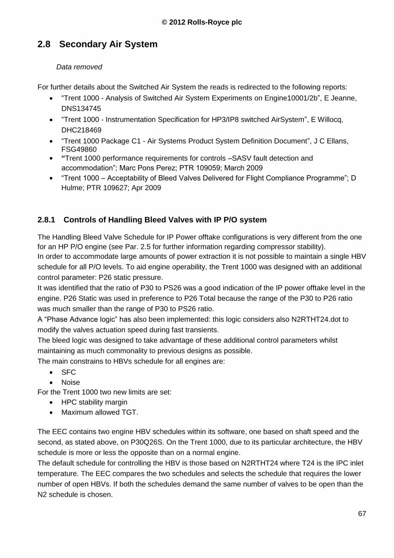
© 2012 Rolls-Royce plc
67
2.8 Secondary Air System
Data removed
For further details about the Switched Air System the reads is redirected to the following reports:
“Trent 1000 - Analysis of Switched Air System Experiments on Engine10001/2b”, E Jeanne,
DNS134745
“Trent 1000 - Instrumentation Specification for HP3/IP8 switched AirSystem”, E Willocq,
DHC218469
“Trent 1000 Package C1 - Air Systems Product System Definition Document”, J C Ellans, FSG49860
“Trent 1000 performance requirements for controls –SASV fault detection and
accommodation”; Marc Pons Perez; PTR 109059; March 2009
“Trent 1000 – Acceptability of Bleed Valves Delivered for Flight Compliance Programme”; D
Hulme; PTR 109627; Apr 2009
2.8.1 Controls of Handling Bleed Valves with IP P/O system
The Handling Bleed Valve Schedule for IP Power offtake configurations is very different from the one
for an HP P/O engine (see Par. 2.5 for further information regarding compressor stability).
In order to accommodate large amounts of power extraction it is not possible to maintain a single HBV
schedule for all P/O levels. To aid engine operability, the Trent 1000 was designed with an additional
control parameter: P26 static pressure.
It was identified that the ratio of P30 to PS26 was a good indication of the IP power offtake level in the
engine. P26 Static was used in preference to P26 Total because the range of the P30 to P26 ratio
was much smaller than the range of P30 to PS26 ratio.
A “Phase Advance logic” has also been implemented: this logic considers also N2RTHT24.dot to
modify the valves actuation speed during fast transients.
The bleed logic was designed to take advantage of these additional control parameters whilst
maintaining as much commonality to previous designs as possible.
The main constrains to HBVs schedule for all engines are:
SFC
Noise
For the Trent 1000 two new limits are set:
HPC stability margin
Maximum allowed TGT.
The EEC contains two engine HBV schedules within its software, one based on shaft speed and the
second, as stated above, on P30Q26S. On the Trent 1000, due to its particular architecture, the HBV
schedule is more or less the opposite than on a normal engine.
The default schedule for controlling the HBV is those based on N2RTHT24 where T24 is the IPC inlet
temperature. The EEC compares the two schedules and selects the schedule that requires the lower
number of open HBVs. If both the schedules demand the same number of valves to be open than the
N2 schedule is chosen.
© 2012 Rolls-Royce plc
68
When conditions with high VFSG load occur then a very high P30s/P26s is registered. This will try to
close more bleeding valves than the N2-based schedule to protect HPC surge margin. The valves will
then be controlled to Pressure Ratio Schedule (Ref. 19).
During starting of the Trent 1000 and when engine is not running, the valves are held open by the
spring pressure.
As stated in Par.2.5.2, the critical condition for the stability of the IPC for this engine is at low thrust
conditions with a small amount of power offtake. When only a small percentage of the design
maximum power is taken from the IP shaft the beneficial effects of the IP P/O system on the IPC
stability are not strong enough to obtain a satisfactory stall margin. In order to maintain an acceptable
stability margin it could be necessary to command one or more IP HBVs open. As shown in Figure
2.8-42, it is clear that when an IP HBV is opened the HPC working line is negatively affected and it
approaches the surge line. At low power conditions the HPC working point is lower than the surge line
and the aforementioned effect does not represent a serious stability issue. On the other hand, when
the HPC surge margin is reduced (i.e. with high level of P/O) and IP bleed is harmful for the HPC,
opening the IP HBV is not required for IPC stability. It can be said that the engine is able to maintain a
considerable stability margin during all conditions above idle (in order to deal with unexpected and
quick changes of power offtake) with a reduced use of the HBVs.
Low idle with low P/O level forces the engine to maintain, particularly in low idle condition, a power
level higher than that actually required. Having an input signal that communicates information about
the rate of change of the required power would be very useful in diminishing the fuel burn during low
power conditions. Additional improvements should result from modulating the rate of change of the
electrical, and thus mechanical, loads. The first benefit is on fuel burn at low speed conditions and the
other is on gear train weight. Reducing the mechanical shocks on gear teeth due to sudden
overloads, starting and transients would allow gears, bearings and shafts to be resized, thus reducing
weight. The effect shown in Figure 2.8-42 does not apply only to IPC and HPC when some amount of
air is extracted from the station 026, it applies also to front and rear stages of the same compressor
when the air is taken from an intermediate stage. On Pack B engines the IPC drum is pressurized
using IP5 bleed instead of IP8, as on Pack A T1000. The IP8 bleed is therefore diminished. This
reduces the performance of rear stages of the IPC, (Talk with Arthur)
The effect of the Switched air System has an impact on core matching since the bleed point is moved
forward (IP8) at high power or backward (HP3) at low power conditions. This modifies the working
point of the first portion of the HPC
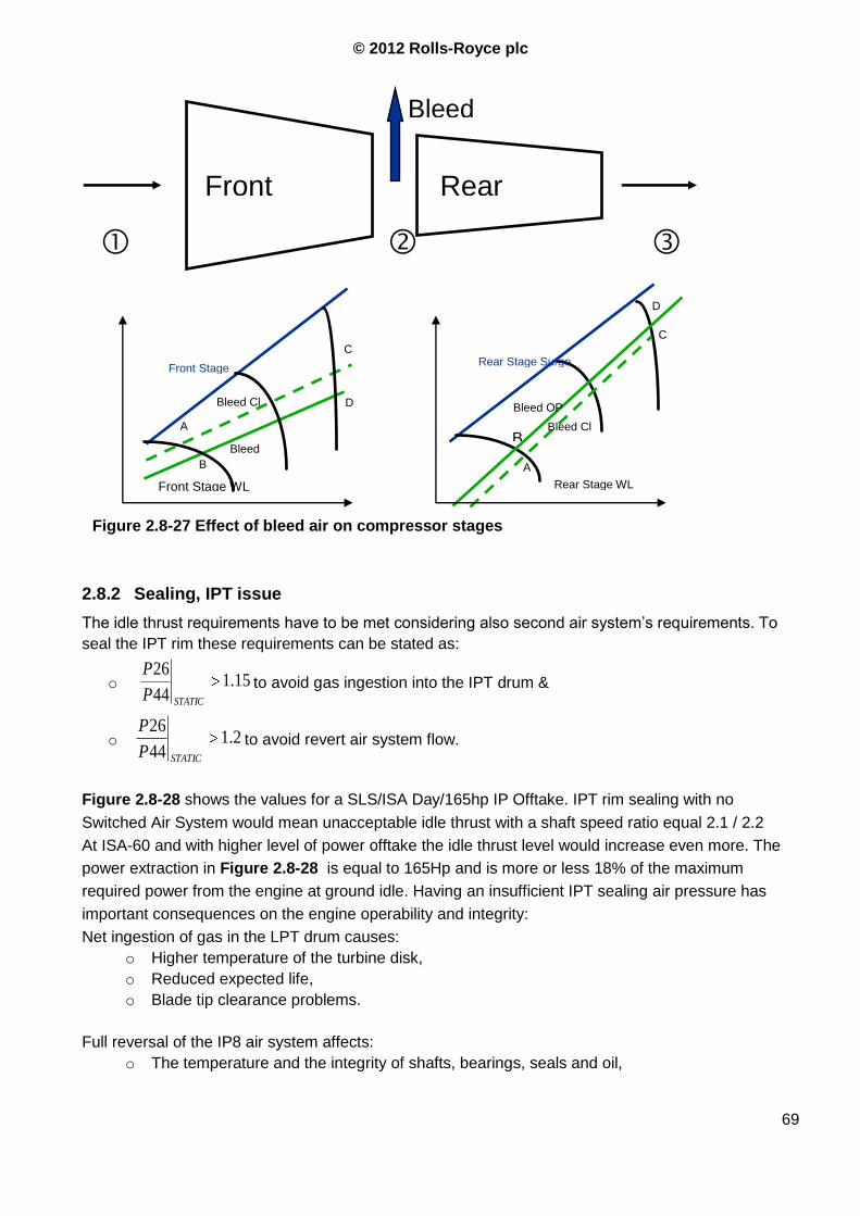
© 2012 Rolls-Royce plc
69
2.8.2 Sealing, IPT issue
The idle thrust requirements have to be met considering also second air system‟s requirements. To
seal the IPT rim these requirements can be stated as:
o 15.144
26
STATICP
Pto avoid gas ingestion into the IPT drum &
o 2.144
26
STATICP
Pto avoid revert air system flow.
Figure 2.8-28 shows the values for a SLS/ISA Day/165hp IP Offtake. IPT rim sealing with no
Switched Air System would mean unacceptable idle thrust with a shaft speed ratio equal 2.1 / 2.2
At ISA-60 and with higher level of power offtake the idle thrust level would increase even more. The
power extraction in Figure 2.8-28 is equal to 165Hp and is more or less 18% of the maximum
required power from the engine at ground idle. Having an insufficient IPT sealing air pressure has
important consequences on the engine operability and integrity:
Net ingestion of gas in the LPT drum causes:
o Higher temperature of the turbine disk,
o Reduced expected life,
o Blade tip clearance problems.
Full reversal of the IP8 air system affects:
o The temperature and the integrity of shafts, bearings, seals and oil,
Figure 2.8-27 Effect of bleed air on compressor stages
Front
Stages
Rear
Stages
Bleed
Front Stage
Surge Line Bleed Cl
Bleed
Op
D
A
B
C
Front Stage WL
A
B
C
D
Rear Stage Surge
Line
Bleed Cl
Rear Stage WL
Bleed OP
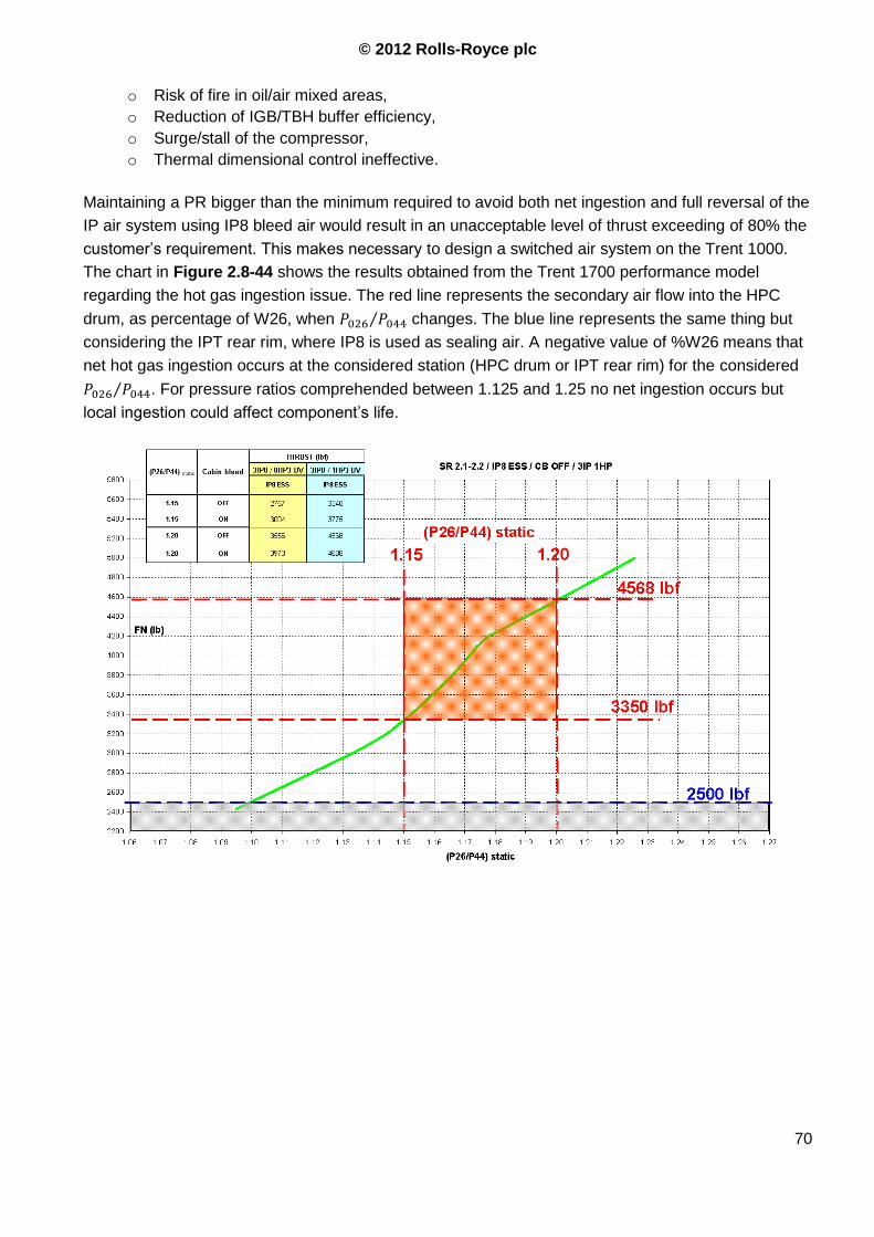
© 2012 Rolls-Royce plc
70
o Risk of fire in oil/air mixed areas,
o Reduction of IGB/TBH buffer efficiency,
o Surge/stall of the compressor,
o Thermal dimensional control ineffective.
Maintaining a PR bigger than the minimum required to avoid both net ingestion and full reversal of the
IP air system using IP8 bleed air would result in an unacceptable level of thrust exceeding of 80% the
customer‟s requirement. This makes necessary to design a switched air system on the Trent 1000.
The chart in Figure 2.8-44 shows the results obtained from the Trent 1700 performance model
regarding the hot gas ingestion issue. The red line represents the secondary air flow into the HPC
drum, as percentage of W26, when changes. The blue line represents the same thing but
considering the IPT rear rim, where IP8 is used as sealing air. A negative value of %W26 means that
net hot gas ingestion occurs at the considered station (HPC drum or IPT rear rim) for the considered
. For pressure ratios comprehended between 1.125 and 1.25 no net ingestion occurs but
local ingestion could affect component‟s life.
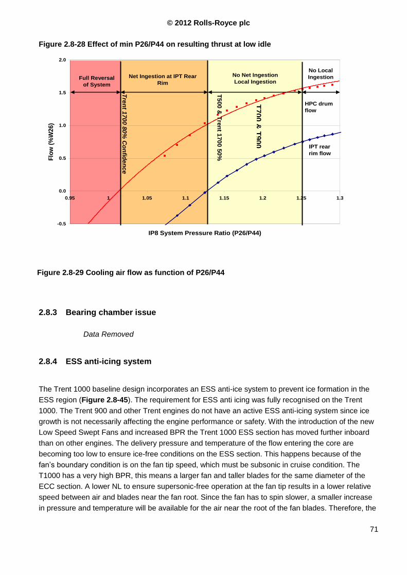
© 2012 Rolls-Royce plc
71
Figure 2.8-28 Effect of min P26/P44 on resulting thrust at low idle
2.8.3 Bearing chamber issue
Data Removed
2.8.4 ESS anti-icing system
The Trent 1000 baseline design incorporates an ESS anti-ice system to prevent ice formation in the
ESS region (Figure 2.8-45). The requirement for ESS anti icing was fully recognised on the Trent
1000. The Trent 900 and other Trent engines do not have an active ESS anti-icing system since ice
growth is not necessarily affecting the engine performance or safety. With the introduction of the new
Low Speed Swept Fans and increased BPR the Trent 1000 ESS section has moved further inboard
than on other engines. The delivery pressure and temperature of the flow entering the core are
becoming too low to ensure ice-free conditions on the ESS section. This happens because of the
fan‟s boundary condition is on the fan tip speed, which must be subsonic in cruise condition. The
T1000 has a very high BPR, this means a larger fan and taller blades for the same diameter of the
ECC section. A lower NL to ensure supersonic-free operation at the fan tip results in a lower relative
speed between air and blades near the fan root. Since the fan has to spin slower, a smaller increase
in pressure and temperature will be available for the air near the root of the fan blades. Therefore, the
Figure 2.8-29 Cooling air flow as function of P26/P44
-0.5
0.0
0.5
1.0
1.5
2.0
0.95 1 1.05 1.1 1.15 1.2 1.25 1.3
IP8 System Pressure Ratio (P26/P44)
Flo
w (
%W
26
)
Net Ingestion at IPT Rear
Rim
No Net Ingestion
Local Ingestion Full Reversal
of System
IPT rear
rim flow
HPC drum
flow
No Local
Ingestion
T5
00
& T
ren
t 170
0 5
0%
Co
nfid
en
ce
Idle
T70
0 &
T90
0
Idle
Tre
nt 1
70
0 8
0%
Co
nfid
en
ce
Idle

© 2012 Rolls-Royce plc
72
Trent 1000 uses IP8 air to supply the ESS vanes. Using air from the IP compressor the ESS air
system improves the stability at low power/low offtake conditions (power offtake drops the working
line while at high power condition the surge margin is usually larger), reducing the necessity to use
HBV bleeding.
o The ESS anti-icing system takes air from the I compressor and therefore drops its working
line. The design point of the ESS bleed system is in the same order of magnitude than the IP
HBV (Ref. 19) . The surge margin benefit coming from the ESS anti-icing is slightly offset as
re-entry of air into the gas path can possibly cause a surge line effect. The IP compressor
stability assessment was therefore made for the critical case where the ESS anti-ice valves
failed closed.
o For the HP compressor, the ESS anti-ice offtake acts as an IP handling bleed valve, and
therefore raises its working line. The HP compressor stability assessment was made for the
worst case, which is with ESS anti-icing flowing.
2.8.5 Reliability – FMECA issues
Data removed
Figure 2.8-30 Trent 1000 ESS anti iceing system

© 2012 Rolls-Royce plc
73
3 PART THREE – ANALISYS OF THE IP P/O SYSTEM
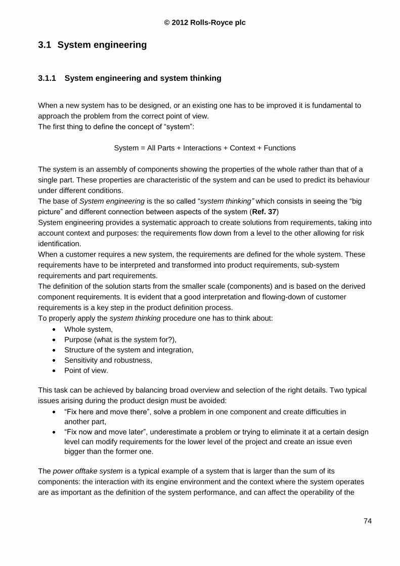
© 2012 Rolls-Royce plc
74
3.1 System engineering
3.1.1 System engineering and system thinking
When a new system has to be designed, or an existing one has to be improved it is fundamental to
approach the problem from the correct point of view.
The first thing to define the concept of “system”:
System = All Parts + Interactions + Context + Functions
The system is an assembly of components showing the properties of the whole rather than that of a
single part. These properties are characteristic of the system and can be used to predict its behaviour
under different conditions.
The base of System engineering is the so called “system thinking” which consists in seeing the “big
picture” and different connection between aspects of the system (Ref. 37)
System engineering provides a systematic approach to create solutions from requirements, taking into
account context and purposes: the requirements flow down from a level to the other allowing for risk
identification.
When a customer requires a new system, the requirements are defined for the whole system. These
requirements have to be interpreted and transformed into product requirements, sub-system
requirements and part requirements.
The definition of the solution starts from the smaller scale (components) and is based on the derived
component requirements. It is evident that a good interpretation and flowing-down of customer
requirements is a key step in the product definition process.
To properly apply the system thinking procedure one has to think about:
Whole system,
Purpose (what is the system for?),
Structure of the system and integration,
Sensitivity and robustness,
Point of view.
This task can be achieved by balancing broad overview and selection of the right details. Two typical
issues arising during the product design must be avoided:
“Fix here and move there”, solve a problem in one component and create difficulties in
another part,
“Fix now and move later”, underestimate a problem or trying to eliminate it at a certain design
level can modify requirements for the lower level of the project and create an issue even
bigger than the former one.
The power offtake system is a typical example of a system that is larger than the sum of its
components: the interaction with its engine environment and the context where the system operates
are as important as the definition of the system performance, and can affect the operability of the
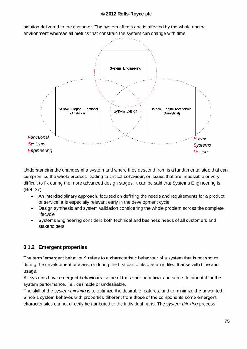
© 2012 Rolls-Royce plc
75
solution delivered to the customer. The system affects and is affected by the whole engine
environment whereas all metrics that constrain the system can change with time.
Understanding the changes of a system and where they descend from is a fundamental step that can
compromise the whole product, leading to critical behaviour, or issues that are impossible or very
difficult to fix during the more advanced design stages. It can be said that Systems Engineering is
(Ref. 37):
An interdisciplinary approach, focused on defining the needs and requirements for a product
or service. It is especially relevant early in the development cycle
Design synthesis and system validation considering the whole problem across the complete
lifecycle
Systems Engineering considers both technical and business needs of all customers and
stakeholders
3.1.2 Emergent properties
The term “emergent behaviour” refers to a characteristic behaviour of a system that is not shown
during the development process, or during the first part of its operating life. It arise with time and
usage.
All systems have emergent behaviours: some of these are beneficial and some detrimental for the
system performance, i.e., desirable or undesirable.
The skill of the system thinking is to optimize the desirable features, and to minimize the unwanted.
Since a system behaves with properties different from those of the components some emergent
characteristics cannot directly be attributed to the individual parts. The system thinking process
Functional
Systems
Engineering
Power
Systems
Design
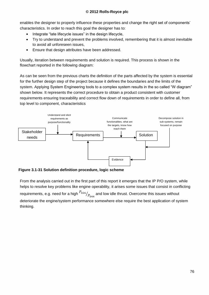
© 2012 Rolls-Royce plc
76
enables the designer to properly influence these properties and change the right set of components‟
characteristics. In order to reach this goal the designer has to:
Integrate “late lifecycle issues” in the design lifecycle,
Try to understand and prevent the problems involved, remembering that it is almost inevitable
to avoid all unforeseen issues,
Ensure that design attributes have been addressed.
Usually, iteration between requirements and solution is required. This process is shown in the
flowchart reported in the following diagram:
As can be seen from the previous charts the definition of the parts affected by the system is essential
for the further design step of the project because it defines the boundaries and the limits of the
system. Applying System Engineering tools to a complex system results in the so called “W diagram”
shown below. It represents the correct procedure to obtain a product consistent with customer
requirements ensuring traceability and correct flow down of requirements in order to define all, from
top level to component, characteristics
From the analysis carried out in the first part of this report it emerges that the IP P/O system, while
helps to resolve key problems like engine operability, it arises some issues that consist in conflicting
requirements, e.g. need for a high and low idle thrust. Overcome this issues without
deteriorate the engine/system performance somewhere else require the best application of system
thinking.
Stakeholder
needs Requirements Solution
Evidence
Understand and elicit
requirements as
purpose/functionality
Communicate
functionalities, what are
the targets, know how
reach them
Decompose solution in
sub-systems, remain
focused on purpose
Figure 3.1-31 Solution definition procedure, logic scheme
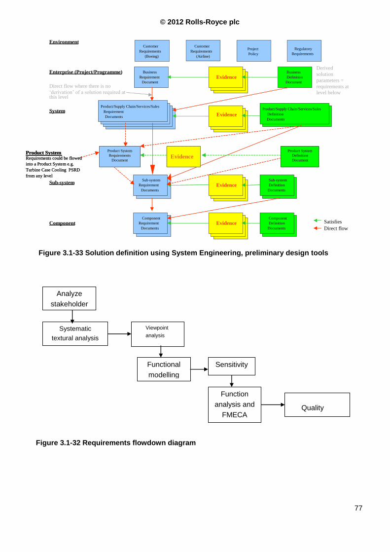
© 2012 Rolls-Royce plc
77
Analyze
stakeholder
Systematic
textural analysis
Viewpoint
analysis
Functional
modelling
Sensitivity
Function
analysis and
FMECA Quality
Function
Diagram
Figure 3.1-33 Solution definition using System Engineering, preliminary design tools
Environment
Enterprise (Project/Programme)
System
Sub - system
Component
Customer Requirements
(Boeing) Project Policy
Regulatory Requirements
Customer Requirements
(Airline)
Business Requirement
Document
Requirement Document Product/Supply Chain/Services/Sales
Requirement Documents
Requirement Document Product/Supply Chain/Services/Sales
Definition Documents
Business Definition
Document Evidence
Evidence
Satisfies Direct flow
Sub - system Requirement
Documents Evidence
Sub - system Definition
Documents
Component Requirement
Documents Evidence
Component Definition
Documents
Direct flow where there is no ‘derivation’ of a solution required at this level
Derived solution parameters = requirements at level below
Evidence Product System Product System Requirements
Document
Product System Definition Document Requirements could be flowed
into a Product System e.g. Turbine Case Cooling PSRD from any level
EE Product System Product System
Requirements Document
Product System Definition Document Requirements could be flowed
into a Product System e.g. Turbine Case Cooling PSRD from any level
Evidence
Figure 3.1-32 Requirements flowdown diagram
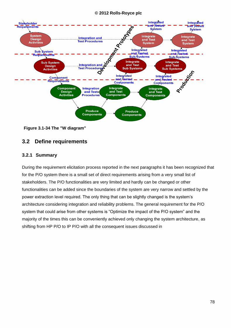
© 2012 Rolls-Royce plc
78
3.2 Define requirements
3.2.1 Summary
During the requirement elicitation process reported in the next paragraphs it has been recognized that
for the P/O system there is a small set of direct requirements arising from a very small list of
stakeholders. The P/O functionalities are very limited and hardly can be changed or other
functionalities can be added since the boundaries of the system are very narrow and settled by the
power extraction level required. The only thing that can be slightly changed is the system‟s
architecture considering integration and reliability problems. The general requirement for the P/O
system that could arise from other systems is “Optimize the impact of the P/O system” and the
majority of the times this can be conveniently achieved only changing the system architecture, as
shifting from HP P/O to IP P/O with all the consequent issues discussed in
Figure 3.1-34 The "W diagram"
© 2012 Rolls-Royce plc
79
Summary
The progressive increase of power extracted from the engine for the electrical aircraft has raised the
issue of the competitive position of 2-shaft vs. 3-shaft engines and, within the 3-shaft architecture, the
effects of using a different shaft to drive the accessory gearbox.
The aim of this report is to define the key parameters and features of an IP P/O system, how they
are influenced, what are the systems and stakeholders involved and, qualitatively, how they are
influenced. This is done in order to explain and better understand the decisions made during the
design and development of the T1000, why certain solutions have been selected and others rejected,
which areas of P/O design require particular attention and what are the lessons learnt.
The first part of this document is aimed at better understanding the theory and the rationale behind
the IP P/O system and its influences on the engine. In order to do this different topics are discussed,
starting from Load requirements, Idle setting, Engine weight, Fuel burn, Starting performance,
Thermodynamic and Mechanical aspects, Secondary air system features and Noise.
The second part is aimed at reviewing the design procedure using the Systems Thinking
approach, i.e. considering the P/O system not just as the sum of its components but as a system
with different properties, functions and effects. The review of the design process starts from the
Definition of Requirements, proceeds with the Stakeholders Analysis (only the most affected
are considered in detail) and ends with a review of the system on the actual engine (Trent 1000
Pack B): relation between requirements, functions and implementation, review of ERMS and
Lessons Learnt databases and FMECA report.
PART ONE – Understanding of the IP Power Offtake system.
From the integration point of view the P/O system is taken as a datum since, once that the
architecture has been decided, its effect on other systems depends only on the amount of power
extracted which is a requirement arising from the airframer and cannot be changed. The other engine
systems, due to their greater design flexibility, are optimized in order to mitigate the power offtake
impact on the engine performance and operability.
Because of this, the “requirements flow” is larger from the P/O system towards other systems rather
than from other systems to the P/O.
3.2.2 Requirements of the IP P/O system
Usually, the customers do not provide a complete set of requirements. The available list is often
inappropriate for direct use, thus some work has to be done to produce a proper requirements
document. Within Rolls Royce six techniques are used to explicit a full set of design requirements.
The first technique is a basic stakeholder requirements elicitation, and it is carried out in five steps
that use different techiques:
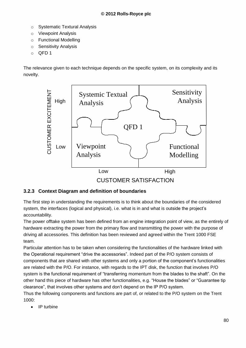
© 2012 Rolls-Royce plc
80
o Systematic Textural Analysis
o Viewpoint Analysis
o Functional Modelling
o Sensitivity Analysis
o QFD 1
The relevance given to each technique depends on the specific system, on its complexity and its
novelty.
3.2.3 Context Diagram and definition of boundaries
The first step in understanding the requirements is to think about the boundaries of the considered
system, the interfaces (logical and physical), i.e. what is in and what is outside the project‟s
accountability.
The power offtake system has been defined from an engine integration point of view, as the entirely of
hardware extracting the power from the primary flow and transmitting the power with the purpose of
driving all accessories. This definition has been reviewed and agreed within the Trent 1000 FSE
team.
Particular attention has to be taken when considering the functionalities of the hardware linked with
the Operational requirement “drive the accessories”. Indeed part of the P/O system consists of
components that are shared with other systems and only a portion of the component‟s functionalities
are related with the P/O. For instance, with regards to the IPT disk, the function that involves P/O
system is the functional requirement of “transferring momentum from the blades to the shaft”. On the
other hand this piece of hardware has other functionalities, e.g. “House the blades” or “Guarantee tip
clearance”, that involves other systems and don‟t depend on the IP P/O system.
Thus the following components and functions are part of, or related to the P/O system on the Trent
1000:
IP turbine
AssumedThose features that
while not basic are
taken for granted and
not worth mentioning
CUSTOMER SATISFACTION
CU
ST
OM
ER
EX
CIT
EM
EN
T
High
Low
Low High
BasicThe fundamentalfeatures and aspectsso obvious that theyare not worth mentioning
DelightWhen deliver allthe expressed,Basic andAssumed requirements
ExpressedFeatures and aspectsverbalised bythe customer
Systemic Textual
Analysis
Systemic Textual
Analysis
Viewpoint
Analysis
Viewpoint
Analysis
Functional
Modelling
Functional
Modelling
Sensitivity
Analysis
Sensitivity
Analysis
QFD 1QFD 1
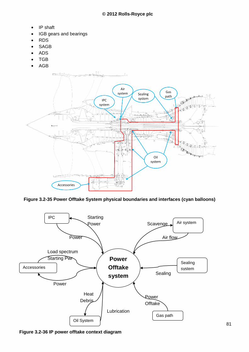
© 2012 Rolls-Royce plc
81
IP shaft
IGB gears and bearings
RDS
SAGB
ADS
TGB
AGB
Figure 3.2-35 Power Offtake System physical boundaries and interfaces (cyan balloons)
Power
Offtake
system
Gas path
Oil System
Sealing
system Accessories
Air system
IPC
System
Power
Offtake
Lubrication
Load spectrum
Starting Pwr
Power
Starting
Power Scavenge
Air flow
Sealing
Heat
Debris
Power
Figure 3.2-36 IP power offtake context diagram
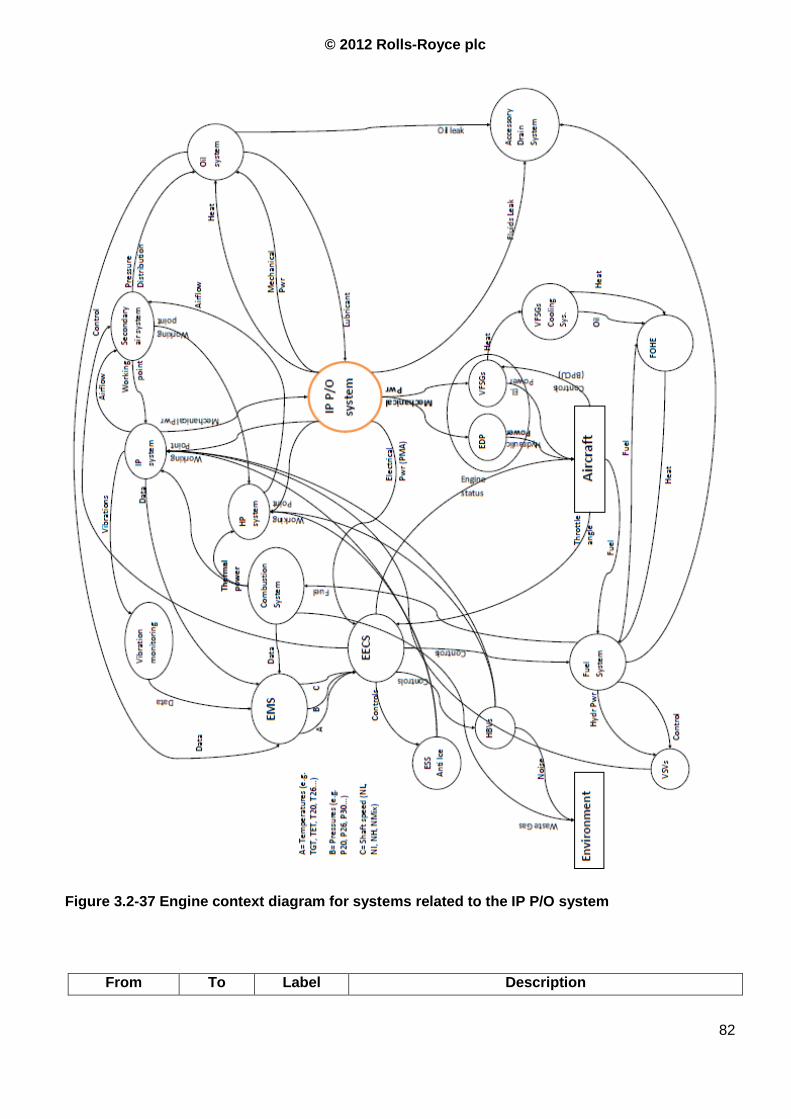
© 2012 Rolls-Royce plc
82
From To Label Description
Figure 3.2-37 Engine context diagram for systems related to the IP P/O system
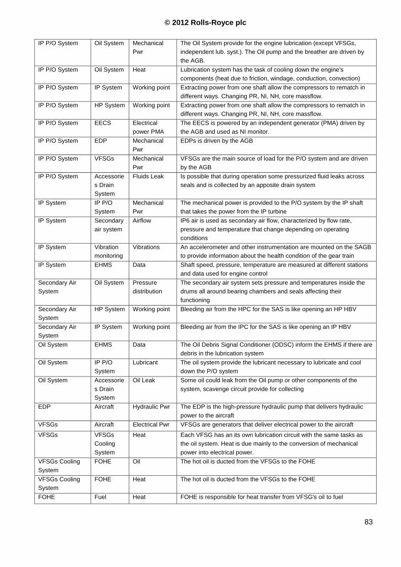
© 2012 Rolls-Royce plc
83
IP P/O System Oil System Mechanical
Pwr
The Oil System provide for the engine lubrication (except VFSGs,
independent lub. syst.). The Oil pump and the breather are driven by
the AGB.
IP P/O System Oil System Heat Lubrication system has the task of cooling down the engine's
components (heat due to friction, windage, conduction, convection)
IP P/O System IP System Working point Extracting power from one shaft allow the compressors to rematch in
different ways. Changing PR, NI, NH, core massflow.
IP P/O System HP System Working point Extracting power from one shaft allow the compressors to rematch in
different ways. Changing PR, NI, NH, core massflow.
IP P/O System EECS Electrical
power PMA
The EECS is powered by an independent generator (PMA) driven by
the AGB and used as NI monitor.
IP P/O System EDP Mechanical
Pwr
EDPs is driven by the AGB
IP P/O System VFSGs Mechanical
Pwr
VFSGs are the main source of load for the P/O system and are driven
by the AGB
IP P/O System Accessorie
s Drain
System
Fluids Leak Is possible that during operation some pressurized fluid leaks across
seals and is collected by an apposite drain system
IP System IP P/O
System
Mechanical
Pwr
The mechanical power is provided to the P/O system by the IP shaft
that takes the power from the IP turbine
IP System Secondary
air system
Airflow IP6 air is used as secondary air flow, characterized by flow rate,
pressure and temperature that change depending on operating
conditions
IP System Vibration
monitoring
Vibrations An accelerometer and other instrumentation are mounted on the SAGB
to provide information about the health condition of the gear train
IP System EHMS Data Shaft speed, pressure, temperature are measured at different stations
and data used for engine control
Secondary Air
System
Oil System Pressure
distribution
The secondary air system sets pressure and temperatures inside the
drums all around bearing chambers and seals affecting their
functioning
Secondary Air
System
HP System Working point Bleeding air from the HPC for the SAS is like opening an HP HBV
Secondary Air
System
IP System Working point Bleeding air from the IPC for the SAS is like opening an IP HBV
Oil System EHMS Data The Oil Debris Signal Conditioner (ODSC) inform the EHMS if there are
debris in the lubrication system
Oil System IP P/O
System
Lubricant The oil system provide the lubricant necessary to lubricate and cool
down the P/O system
Oil System Accessorie
s Drain
System
Oil Leak Some oil could leak from the Oil pump or other components of the
system, scavenge circuit provide for collecting
EDP Aircraft Hydraulic Pwr The EDP is the high-pressure hydraulic pump that delivers hydraulic
power to the aircraft
VFSGs Aircraft Electrical Pwr VFSGs are generators that deliver electrical power to the aircraft
VFSGs VFSGs
Cooling
System
Heat Each VFSG has an its own lubrication circuit with the same tasks as
the oil system. Heat is due mainly to the conversion of mechanical
power into electrical power.
VFSGs Cooling
System
FOHE Oil The hot oil is ducted from the VFSGs to the FOHE
VFSGs Cooling
System
FOHE Heat The hot oil is ducted from the VFSGs to the FOHE
FOHE Fuel Heat FOHE is responsible for heat transfer from VFSG's oil to fuel
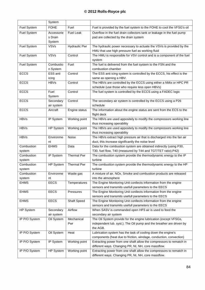
© 2012 Rolls-Royce plc
84
System
Fuel System FOHE Fuel Fuel is provided by the fuel system to the FOHE to cool the VFSG's oil
Fuel System Accessorie
s Drain
System
Fuel Leak Overflow in the fuel drain collectors tank or leakage in the fuel pump
pad are collected by the drain system
Fuel System VSVs Hydraulic Pwr The hydraulic power necessary to actuate the VSVs is provided by the
HMU that use high pressure fuel as working fluid
Fuel System VSVs Control The HMU is responsible for VSV control and is a component of the fuel
system
Fuel System Combustio
n System
Fuel The fuel is delivered from the fuel system to the FSN and the
combustion chamber
ECCS ESS anti
icing
Control The ESS anti icing system is controlled by the ECCS, his effect is the
same as opening a HBV.
ECCS HBVs Control The HBVs are controlled by the ECCS using either a NMix or HPC PR
schedule (use those who require less open HBVs)
ECCS Fuel
System
Control The fuel system is controlled by the ECCS using a FADEC logic
ECCS Secondary
air system
Control The secondary air system is controlled by the ECCS using a P26
schedule
ECCS Aircraft Engine status The information about the engine status are sent from the ECS to the
flight deck
HBVs IP System Working point The HBVs are used appositely to modify the compressors working line
thus increasing operability
HBVs HP System Working point The HBVs are used appositely to modify the compressors working line
thus increasing operability
HBVs Environme
nt
Noise The HBVs extract high pressure air that is discharged into the fan air
duct, this increase significantly the noise level
Combustion
system
EHMS Data Data for the combustion system are obtained indirectly (using P30,
T30, fuel flow, T40 (measured by T44 and TGT/TET ratio),P42)
Combustion
system
IP System Thermal Pwr The combustion system provide the thermodynamic energy to the IP
turbine
Combustion
system
HP System Thermal Pwr The combustion system provide the thermodynamic energy to the HP
turbine
Combustion
system
Environme
nt
Waste gas A mixture of air, NOx, Smoke and combustion products are released
into the atmosphere
EHMS EECS Temperatures The Engine Monitoring Unit conllects information from the engine
sensors and transmits usefull parameters to the EECS
EHMS EECS Pressures The Engine Monitoring Unit conllects information from the engine
sensors and transmits usefull parameters to the EECS
EHMS EECS Shaft Speed The Engine Monitoring Unit conllects information from the engine
sensors and transmits usefull parameters to the EECS
HP System Secondary
air system
Airflow When SASV is commanded open HP3 air is used to feed the
secondary air system
IP P/O System Oil System Mechanical
Pwr
The Oil System provide for the engine lubrication (except VFSGs,
independent lub. syst.). The Oil pump and the breather are driven by
the AGB.
IP P/O System Oil System Heat Lubrication system has the task of cooling down the engine's
components (heat due to friction, windage, conduction, convection)
IP P/O System IP System Working point Extracting power from one shaft allow the compressors to rematch in
different ways. Changing PR, NI, NH, core massflow.
IP P/O System HP System Working point Extracting power from one shaft allow the compressors to rematch in
different ways. Changing PR, NI, NH, core massflow.
© 2012 Rolls-Royce plc
85
Table Errore. Per applicare Heading 2 al testo da visualizzare in questo punto, utilizzare la scheda
Home.-2 Engine Context diagram legenda (Function DIctionary)
3.2.4 Stakeholder analysis
A stakeholder is a person, a group of people or another subject that is affected by a subject matter, or
that can influence it. The stakeholder‟s influence on project execution, the level at which a stakeholder
is affected by the project itself, its position regarding the project, its interest in it, what can go wrong
with negatively affected stakeholders are all points that have to be considered.
In order to capture the stakeholder‟s requirements the questions under consideration are:
“what is needed to enable an IP power offtake system to be developed?” (“bottom up”
approach),
“what do all the stakeholders want?”, ( “top down” approach).
Both approaches have strengths and weaknesses: indeed the bottom up method is easier but can fail
to capture key requirements while the latter is more complicated but addresses the limitations of the
former.
To help us identifying the stakeholders we can try to answer 4 questions: o To whom
–Who will accept servicing of the product – throughout its life?
o For whom
–Who is the product for – throughout its life?
o From whom
–Who will provide the solution creator, i.e. RR, with a service/product?
o Through whom
–Who will allow the product/service to be „exercised‟?
The list of stakeholders reported in Table 3.2-3 is a top-level analysis of the subjercts that have to be
involved into the design of the power offtake system to successfully integrate it with the whole engine.
For the IP P/O system, while the hardware is easily identifiable and can be located in a restricted area
of the engine, the functional impact on other systems is so broad and relevant that it affects the other
teams thinking to achieve solutions. Whilst teams accountable for the systems influenced by power
extraction have to take into account the P/O effects, the power extraction system is only marginally
affected by other systems‟ solutions.
While there were not many changes of requirements with regard to the basic function of gears, shafts
and bearings during the Trent 1000 and Trent XWB EDP the issues related to the variability of the
power extraction level have turned out to be of high importance. It is because of this that the
interaction with Airframe manufacturer, Airline operator and suppliers of accessories is very important
and strongly recommended. This is particularly important during the first stage of the design process
in order to have the best possible understanding of the effective loads. The importance of the
interactions with other design teams stems from the fact that the higher the power extracted the
stronger the influence on the whole engine
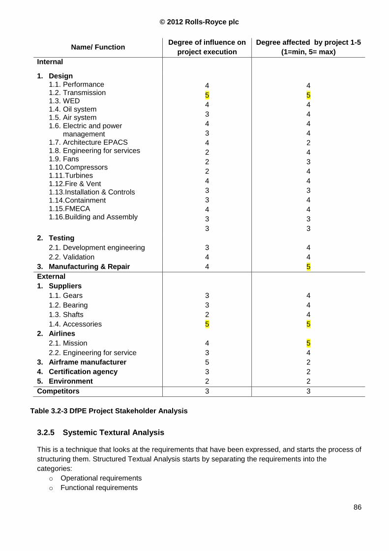
© 2012 Rolls-Royce plc
86
Name/ Function Degree of influence on
project execution
Degree affected by project 1-5
(1=min, 5= max)
Internal
1. Design 1.1. Performance 1.2. Transmission 1.3. WED 1.4. Oil system 1.5. Air system 1.6. Electric and power
management 1.7. Architecture EPACS 1.8. Engineering for services 1.9. Fans 1.10. Compressors 1.11. Turbines 1.12. Fire & Vent 1.13. Installation & Controls 1.14. Containment 1.15. FMECA 1.16. Building and Assembly
4
5
4
3
4
3
4
2
2
2
4
3
3
4
3
3
4
5
4
4
4
4
2
4
3
4
4
3
4
4
3
3
2. Testing
2.1. Development engineering
2.2. Validation
3
4
4
4
3. Manufacturing & Repair 4 5
External
1. Suppliers
1.1. Gears
1.2. Bearing
1.3. Shafts
1.4. Accessories
2. Airlines
2.1. Mission
2.2. Engineering for service
3. Airframe manufacturer
4. Certification agency
5. Environment
3
3
2
5
4
3
5
3
2
4
4
4
5
5
4
2
2
2
Competitors 3 3
3.2.5 Systemic Textural Analysis
This is a technique that looks at the requirements that have been expressed, and starts the process of
structuring them. Structured Textual Analysis starts by separating the requirements into the
categories:
o Operational requirements
o Functional requirements
Table 3.2-3 DfPE Project Stakeholder Analysis
© 2012 Rolls-Royce plc
87
o Non-functional requirements
This procedure is very useful when there is input documentation from customers that is considered
incomplete, or when the requirements come from a range of customers.
Applying this analysis to the power offtake system allows to identify only a small part of the system
requirements because the customers define only top level functions and characteristics that flow
down in this system. The spreadsheet that contains the aforementioned process is reported in the
SysTexturalAnalysis.xls spreadsheet and reported below.
Identify key product attributes (What are the target as weight, reliability, power requirements
etc?)
The design loads are reported in Errore. L'origine riferimento non è stata trovata. and
Table 3.2-5,
There are no specific requirements on the system‟s weight, the engine should have a dry
weight of less than 11.920lbs
The VFSGs frequency range for steady state conditions, the lower limit can be shifted to a
lower value for no longer than X sec.
The PMA must be able to power the EECS at sub-idle condition
There are no explicit limits for the Engine Driven Pump
The engine mean time to shop visit shall, as a goal, be no less than 10.000 Engine Flight
Hours (EFH) or 8.000 cycles, whichever comes first (Ref. 1, 3.21.3.1).
For ETOPS requirements, the In-Flight shout down rate should be less than 0.01 per 1000
EFH considering all causes (Ref. 1, 3.21.3.1)
The design objective shall be that the engine have a useful on-wing life without repair or
replacement of major components in excess of the hours stated in Table 3.2-4.
Table 3.2-5 Max transient loads (removed)
3.2.6 Viewpoint Analysis
This technique exposes the basic requirements. It is important to capture these, as they are
often not explicitly expressed because, whilst they might raise low technical interest, they
are an enormous source of customer dissatisfaction if they are not met (partly because they are so
basic).
Viewpoint Analysis is a tool that can help a multi-disciplinary team to identify and structure the
functional and non-functional Basic Customer Requirements of a system, i.e. those characteristics
and features that are so obvious that are not specified into the customer documentation. Indeed, the
customer will never provide a complete, consistent and un-ambiguous list of requirements, it is often
up to the System Engineer to derive such a document.
Table 3.2-4 Mature shop visit lives (removed)
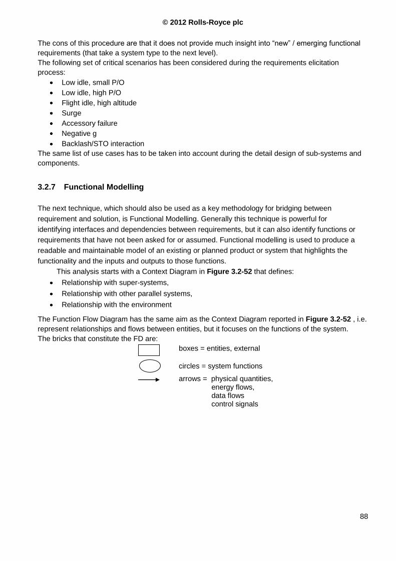
© 2012 Rolls-Royce plc
88
The cons of this procedure are that it does not provide much insight into “new” / emerging functional
requirements (that take a system type to the next level).
The following set of critical scenarios has been considered during the requirements elicitation
process:
Low idle, small P/O
Low idle, high P/O
Flight idle, high altitude
Surge
Accessory failure
Negative g
Backlash/STO interaction
The same list of use cases has to be taken into account during the detail design of sub-systems and
components.
3.2.7 Functional Modelling
The next technique, which should also be used as a key methodology for bridging between
requirement and solution, is Functional Modelling. Generally this technique is powerful for
identifying interfaces and dependencies between requirements, but it can also identify functions or
requirements that have not been asked for or assumed. Functional modelling is used to produce a
readable and maintainable model of an existing or planned product or system that highlights the
functionality and the inputs and outputs to those functions.
This analysis starts with a Context Diagram in Figure 3.2-52 that defines:
Relationship with super-systems,
Relationship with other parallel systems,
Relationship with the environment
The Function Flow Diagram has the same aim as the Context Diagram reported in Figure 3.2-52 , i.e.
represent relationships and flows between entities, but it focuses on the functions of the system.
The bricks that constitute the FD are:
boxes = entities, external
circles = system functions
arrows = physical quantities, energy flows, data flows control signals
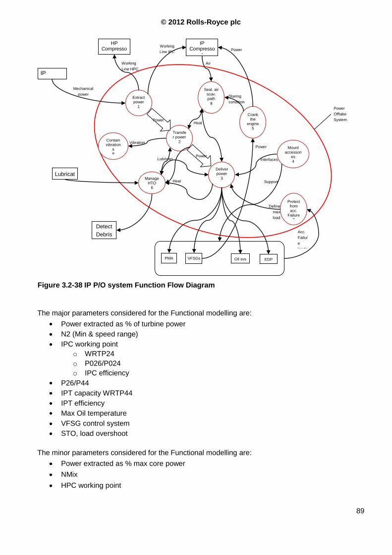
© 2012 Rolls-Royce plc
89
The major parameters considered for the Functional modelling are:
Power extracted as % of turbine power
N2 (Min & speed range)
IPC working point
o WRTP24
o P026/P024
o IPC efficiency
P26/P44
IPT capacity WRTP44
IPT efficiency
Max Oil temperature
VFSG control system
STO, load overshoot
The minor parameters considered for the Functional modelling are:
Power extracted as % max core power
NMix
HPC working point
Extract power
1
Transfer power
2
Deliver power
3 Lubricat
e
Working
Line IPC
Working
Line HPC
EDP Oil sys PMA
Power
Power
IP Compresso
r
HP Compresso
r
Mechanical
power
Detect
Debris
Mount accessori
es 4 Interfaces
Crank the
engine
5
Power
Power
Offtake
System
IP
Turbine
Lubrican
t
Manage HTO
6
Heat
VFSGs
Protect from acc.
Failure 7
Seal. air scav. path
8
Contain vibration
s 9
Power
Heat
Air
Define
max
load
Staring
condition
Acc.
Failur
e
loads
Support
Vibration
Figure 3.2-38 IP P/O system Function Flow Diagram
© 2012 Rolls-Royce plc
90
o WRTP26
o P030/P026
o HPC efficiency
HPT capacity
HPT efficiency
BPR
Idle thrust
While requirements flow down from product characteristics towards component characteristics, the
boundaries can arise from a lower level or from related systems: the system‟s performance is
determined by the limits of its components and by the limits of the other systems involved. It is useful
to start from the outputs and consider what inputs they need, and then think about the elementary
functions of the system.
For the power offtake system the requirements derived from the system analysis (just looking into the
system) don‟t necessarily highlight the main problem. Moreover, they are not very different from the
requirements for an HP P/O system, hence the owned know-how can be used considering the
peculiarities explained in Par. 2.3, 0 and 2.1. The main issues related with the power offtake system,
those that require a deeper investigation in the first design stage, are related to the system interaction
with the whole engine as highlighted in Figure 3.2-53
3.2.8 Sensitivity Analysis
The Sensitivity Analysis, directly using the Functional Modelling output, looks at the issues that
would be in the interest of the customer. When using this technique it needs to be clear that the
identified functions are the ones whose value customers or stakeholders are prepared to pay for or
invest in. Sensitivity analysis provides a “black box” view of the effect the effect of variation in
“flows” (inputs to functions) on the functionality of the system this tool can be used in conjunction
with the FMECA to study how a function can fail. This analysis has not been reported in the
present report.
3.2.9 Quality Functional Deployment
QFD1 is used to integrate together all the techniques described in the previous paragraphs. QFD1 is
an essential technique to ensure robust flow down of requirements through functional definitions. It
enables a check whether there are functions/qualities definitions to address all requirements, and that
all functions address a requirement.
If the level of novelty of the system is not sufficiently high or an existing system only requires an
upgrade, that is our case, functions and stakeholders are known and maybe most of the procedure
has already been performed. There are two possibilities with relative drawbacks:
o Re-doing the analysis from scratch (which can be a significant effort), and may merely
duplicate what was done before (or even miss some bits out) and hence add no value,
© 2012 Rolls-Royce plc
91
o Picking up the analysis from a previous time, and failing to recognise the novel and different
issues or functions required. In this case the best thing is elicit a list of the differences between
the new and the old system and analyze what requirements can be affected, and how, by this
differences
The second option has been considered: the analysis is focused on the differences between the IP
and HP P/O systems and on those fields where a shortfall or a poor understanding has been
identified in Chapter 1.
When the problem is truly mew, and the situation is one where there is an attempt to “change” the
market by “pushing” a new capability that customers are not really familiar with, then the
techniques described above can go wrong on the first iteration. The best practice is to select the
technique that is supposed to be the most sensible, and guess scenarios or use case vignettes. An
idea of a potential solution can be used to extract a definition of functionality, and then
requirements. This then gives a clearer definition of what the capability is. After this, it is possible to
look at stakeholders and their needs in a more informed manner, during a second iteration for
requirements.
The techniques descript in the previous paragraphs produce a heterogeneous set of requirements
that cannot be directly used. To guarantee correct flow-down and traceability of requirements
through the design process it is necessary to sort them into three categories depending on their
impact on the project. This procedure is the same applied during the Systemic Textural Analysis
but it is more detailed and applies to the entire set of requirements, and not only to those directly
expressed by the customers. In order to obtain a complete and structured set, the requirements
have to be divided in:
1. Operational Requirements: define the major purpose of a product/system (i.e. what
it fundamentally does – its capability) together with the key overarching constraints
2. Functional requirements: specify what the product/system has to do in order to
satisfy the Operational Requirements. A functional requirement is a verb or verb
phrase. A phrase can have a verb but not be a function. A good test to check if a
requirement is a Functional Requirement is try to answer the question “does this
system do this or has to be this?” E.g. for a civil aircraft they include:
a. navigate
b. control flight
c. store passengers
d. control cabin environment
e. communicate with other aircraft and ATC
f. Etc.
3. Non-functional requirements: are constraints on the system/product. They define
how a system is to be built in terms of a specific technology. They are solution-based
requirements from customer, legislation or other stakeholder. They fall into three
categories:
a. Non-functional Performance, associated with corresponding Functional
Requirement and define “how well a particular function has to perform”

© 2012 Rolls-Royce plc
92
b. Non-functional System, define constraints that affect the whole system and
include:
i. Physical Attributes, e.g. style, size, weight etc.
ii. The –ilities, e.g. reliability, maintainability, interoperability, deployability
etc
iii. System Performance, e.g. cost, speed, manoeuvrability etc.
iv. Contractual/commercial requirements, e.g. “the system must be ready
for trials by a particular date”.
c. Non-functional Implementation, define how a system is to be built in terms of a
specific technology. They are solution-based requirements from the customer
or legislation.
The output of this procedure cannot be used into the QFD1, another step is required to start this
analysis. The Functional Requirements have to be organized in “function trees” in order to identify
functions and the related sub-functions. This allows to choose the level of detail used to analyze
each function: high, if all the sub-functions are reported into the QFD1 chart, or low, if only the top-
level function is used.
The Functional Requirements fit into the “HOW” box in the QFD chart (Figure 3.2-55).
Operational and Non Functional System requirements fit into the “WHAT” box.
Non-Functional Performance requirements fit into the “HOW MUCH” box.
The results of the aforementioned procedure are reported hereinafter.
Figure 3.2-39 QFD1 structure
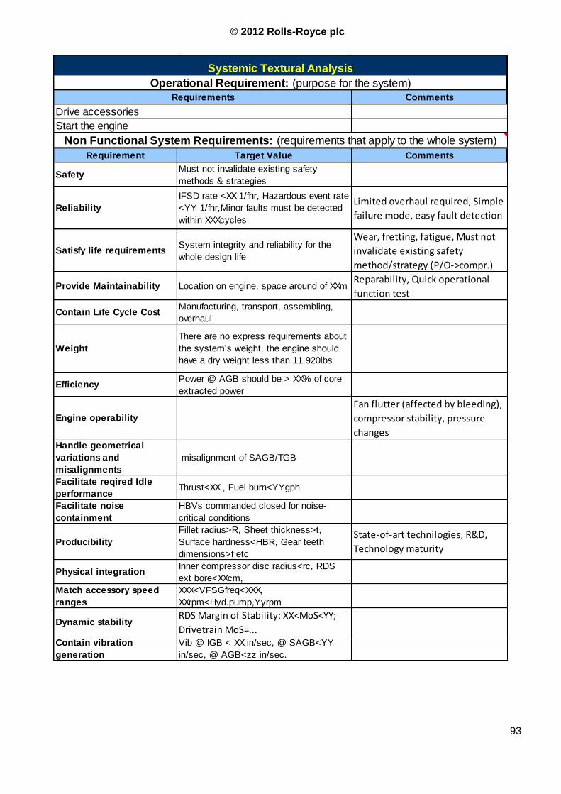
© 2012 Rolls-Royce plc
93
Comments
Requirement Target Value Comments
Safety Must not invalidate existing safety
methods & strategies
Reliability
IFSD rate <XX 1/fhr, Hazardous event rate
<YY 1/fhr,Minor faults must be detected
within XXXcycles
Limited overhaul required, Simple
failure mode, easy fault detection
Satisfy life requirements System integrity and reliability for the
whole design life
Wear, fretting, fatigue, Must not
invalidate existing safety
method/strategy (P/O->compr.)
Provide Maintainability Location on engine, space around of XXmReparability, Quick operational
function test
Contain Life Cycle Cost Manufacturing, transport, assembling,
overhaul
Weight
There are no express requirements about
the system‟s weight, the engine should
have a dry weight less than 11.920lbs
EfficiencyPower @ AGB should be > XX% of core
extracted power
Engine operability
Fan flutter (affected by bleeding),
compressor stability, pressure
changesHandle geometrical
variations and
misalignments
misalignment of SAGB/TGB
Facilitate reqired Idle
performanceThrust<XX , Fuel burn<YYgph
Facilitate noise
containment
HBVs commanded closed for noise-
critical conditions
Producibility
Fillet radius>R, Sheet thickness>t,
Surface hardness<HBR, Gear teeth
dimensions>f etc
State-of-art technilogies, R&D,
Technology maturity
Physical integrationInner compressor disc radius<rc, RDS
ext bore<XXcm,
Match accessory speed
ranges
XXX<VFSGfreq<XXX,
XXrpm<Hyd.pump,Yyrpm
Dynamic stabilityRDS Margin of Stability: XX<MoS<YY;
Drivetrain MoS=...Contain vibration
generation
Vib @ IGB < XX in/sec, @ SAGB<YY
in/sec, @ AGB<zz in/sec.
Non Functional System Requirements: (requirements that apply to the whole system)
Systemic Textural Analysis
Operational Requirement: (purpose for the system)
Requirements
Drive accessories
Start the engine
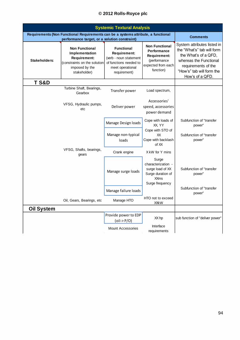
© 2012 Rolls-Royce plc
94
Comments
Stakeholders:
Non Functional
Implementation
Requirement:
(constraints on the solution
imposed by the
stakeholder)
Functional
Requirement:
(verb - noun statement
of functions needed to
meet operational
requirement)
Non Functional
Performance
Requirement:
(performance
expected from each
function)
System attributes listed in
the “What‟s” tab will form
the What‟s of a QFD,
whereas the Functional
requirements of the
“How‟s” tab will form the
How‟s of a QFD.
T S&DTurbine Shaft, Bearings,
GearboxTransfer power Load spectrum,
VFSG, Hydraulic pumps,
etcDeliver power
Accessories'
speed, accessories
power demand
Manage Design loadsCope with loads of
XX, YY
Subfunction of "transfer
power"
Manage non-typical
loads
Cope with STO of
XX
Cope with backlash
of XX
Subfunction of "transfer
power"
VFSG, Shafts, bearings,
gearsCrank engine X kW for Y mins
Manage surge loads
Surge
characterization -
surge load of XX
Surge duration of
XXms
Surge frequency
Subfunction of "transfer
power"
Manage failure loadsSubfunction of "transfer
power"
Oil, Gears, Bearings, etc Manage HTOHTO not to exceed
XXkW
Oil SystemProvide power to EDP
(oil-> P/O)XX hp sub function of "deliver power"
Mount AccessoriesInterface
requirements
Systemic Textural Analysis
Requirements (Non Functional Requirements can be a systems attribute, a functional
performance target, or a solution constraint)
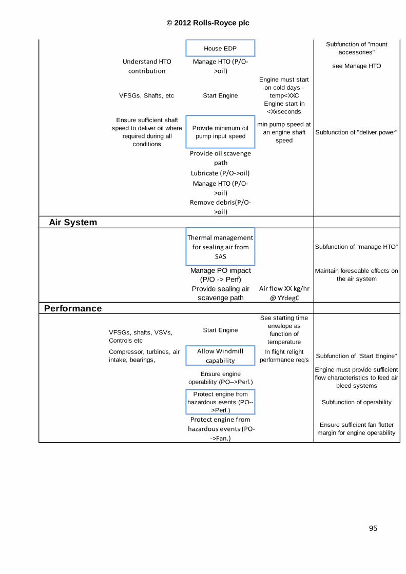
© 2012 Rolls-Royce plc
95
House EDPSubfunction of "mount
accessories"
Understand HTO
contribution
Manage HTO (P/O-
>oil)see Manage HTO
VFSGs, Shafts, etc Start Engine
Engine must start
on cold days -
temp<XXC
Engine start in
<Xxseconds
Ensure sufficient shaft
speed to deliver oil where
required during all
conditions
Provide minimum oil
pump input speed
min pump speed at
an engine shaft
speed
Subfunction of "deliver power"
Provide oil scavenge
path
Lubricate (P/O->oil)
Manage HTO (P/O-
>oil)
Remove debris(P/O-
>oil)
Air System
Thermal management
for sealing air from
SAS
Subfunction of "manage HTO"
Manage PO impact
(P/O -> Perf)
Maintain foreseable effects on
the air system
Provide sealing air
scavenge path
Air flow XX kg/hr
@ YYdegC
Performance
VFSGs, shafts, VSVs,
Controls etc
Start Engine
See starting time
envelope as
function of
temperature
Compressor, turbines, air
intake, bearings,
Allow Windmill
capability
In flight relight
performance req'sSubfunction of "Start Engine"
Ensure engine
operability (PO-->Perf.)
Engine must provide sufficient
flow characteristics to feed air
bleed systems
Protect engine from
hazardous events (PO--
>Perf.)
Subfunction of operability
Protect engine from
hazardous events (PO-
->Fan.)
Ensure sufficient fan flutter
margin for engine operability
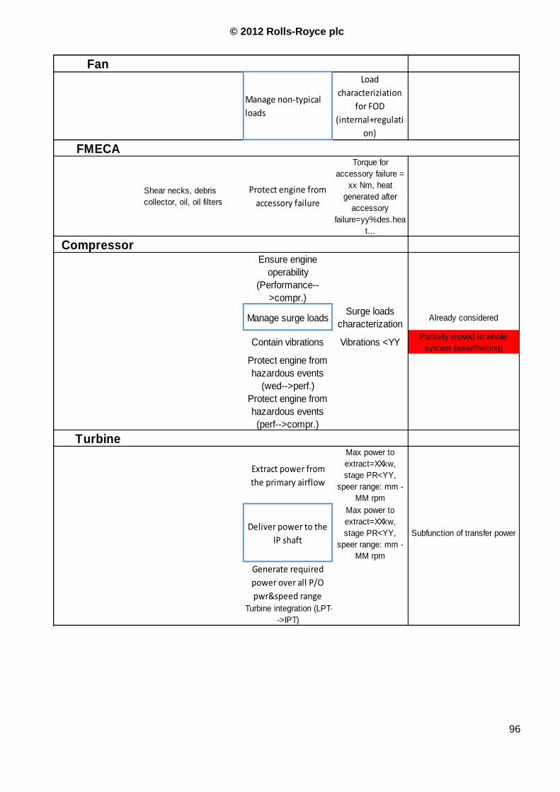
© 2012 Rolls-Royce plc
96
Fan
Manage non-typical
loads
Load
characteriziation
for FOD
(internal+regulati
on)
FMECA
Shear necks, debris
collector, oil, oil filters
Protect engine from
accessory failure
Torque for
accessory failure =
xx Nm, heat
generated after
accessory
failure=yy%des.hea
t...
CompressorEnsure engine
operability
(Performance--
>compr.)
Manage surge loadsSurge loads
characterizationAlready considered
Contain vibrations Vibrations <YYPartially moved to whole
system (wear/fretting)
Protect engine from
hazardous events
(wed-->perf.)
Protect engine from
hazardous events
(perf-->compr.)
Turbine
Extract power from
the primary airflow
Max power to
extract=XXkw,
stage PR<YY,
speer range: mm -
MM rpm
Deliver power to the
IP shaft
Max power to
extract=XXkw,
stage PR<YY,
speer range: mm -
MM rpm
Subfunction of transfer power
Generate required
power over all P/O
pwr&speed range Turbine integration (LPT-
->IPT)

© 2012 Rolls-Royce plc
97
EPACS
VFSGs, PMA, EEC,
ingniters
Start the engine
(EPACS-->airframer)
Power required by
the engine to be
lighted over the
whole envelope
Manage failure loads
Aricraft system
failure derived peak
load=xxkW,
duration=Yyms
Subfunction of transfer
power
Extract power from the
primary airflow (effects
on compressors and
turbine)
Aricraft system
failure derived peak
load=xxkW,
duration=Yyms
Deliver power
Aircraft AC
frequency range=
360-800Hz
Ensure aircraft architecture
and engine speed range are
compatible
Manage PO (EPACS--
>performance)
Figure 3.2-40 IP P/O system Functional Reqirements Tree (Red boxes are top-level functions)
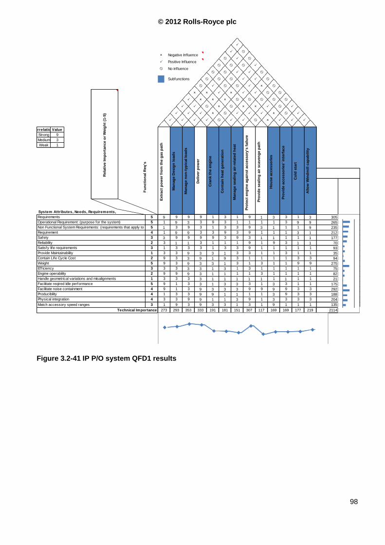
© 2012 Rolls-Royce plc
98
CorrelationsValue
Strong 9
Medium 3
Weak 1
305
265
235
212
177
70
93
35
94
275
75
82
21
175
292
188
204
135
2114 Score307 117 169 169 177 219Technical Importance 273 293 353 333 191 181 151
1 1
9 1 1 19 3 3 1 3 1
9 9 1 1 1 1
3
Match accessory speed ranges 3 1 9 3
3 9 1 3 3 3Physical integration 4 3 3 9 9
3
Producibility 4 1 3 3
3 9 9 9 9 3Facilitate noise containment 4 9 1 3 9 3 3
3 9 3 3
1 1
3 3 1 13 1 3 3 3 1
3 1 1 1 1 3
1
Facilitate reqired Idle performance 5 9 1 3
1 1 1 1 1 1Handle geometrical variations and misalignments 1 3 3 3 3
1
Engine operability 2 9 9 9
1 3 1 1 1 1Efficiency 3 3 3 3 3 1 3
1 1 1 1
1 9
1 1 9 93 3 1 3 1 3
3 3 1 3 3 1
3
Weight 5 9 3 9
3 1 1 1 1 3Contain Life Cycle Cost 2 9 3 3 9
1
Provide Maintainability 1 3 3 9
3 9 1 1 1 1Satisfy life requirements 3 1 3 3 3 1 3
1 3 1 1
9 3
9 3 1 13 1 1 1 9 1
3 3 9 3 9 1
1
Reliability 2 3 1 1
9 3 1 1 1 1Safety 3 3 9 9 9
9
Requirement 4 1 9 9
3 9 3 1 1 1Non Functional System Requirements: (requirements that apply to the w hole system)5 1 3 9 3 1 3
1 1 3 1
3 9 93 9 3 1 1 1Operational Requirement: (purpose for the system) 5 1 9 3
1 9 1 39 9 9 9 1 3
1
System Attributes, Needs, Requirements,
Requirements 5
Ho
use a
ccesso
ries
Pro
vid
e a
ccesso
ries' in
terf
ace
Co
ld s
tart
Allo
w W
ind
mill cap
ab
ilit
y
Extr
act
po
wer
fro
m t
he g
as p
ath
Man
ag
e D
esig
n lo
ad
s
Man
ag
e n
on
-typ
ical lo
ad
s
Deliver
po
wer
Cra
nk t
he e
ng
ine
Co
nta
in h
eat
gen
era
tio
n
Man
ag
e s
ealin
g a
ir-r
ela
ted
heat
Pro
tect
en
gin
e a
gain
st
accesso
ry's
failu
re
Pro
vid
e s
ealin
g a
ir s
caven
ge p
ath
33 1
P
Fu
ncti
on
al R
eq
's
P P P P W
W PP P P O W P
W O P P
W
O P W PP P W O W
P W W
Rela
tive Im
po
rtan
ce o
r W
eig
ht
(1-5
)
O O P O P
O
P P
P O O O W W W W
P P O
WW P W W P O
WSubfunctions W W W P P
W
W No influenceW W P
P Positive InfluenceW W W P
O Negative Influence W P W
P W
P
P
Figure 3.2-41 IP P/O system QFD1 results
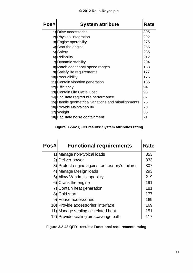
© 2012 Rolls-Royce plc
99
1) Drive accessories 305
2) Physical integration 292
3) Engine operability 275
4) Start the engine 265
5) Safety 235
6) Reliability 212
7) Dynamic stability 204
8) Match accessory speed ranges 188
9) Satisfy life requirements 177
10) Producibility 175
11) Contain vibration generation 135
12) Efficiency 94
13) Contain Life Cycle Cost 93
14) Facilitate reqired Idle performance 82
15) Handle geometrical variations and misalignments 75
16) Provide Maintainability 70
17) Weight 35
18) Facilitate noise containment 21
Pos# System attribute Rate
Figure 3.2-42 QFD1 results: System attributes rating
1) Manage non-typical loads 353
2) Deliver power 333
3) Protect engine against accessory's failure 307
4) Manage Design loads 293
5) Allow Windmill capability 219
6) Crank the engine 191
7) Contain heat generation 181
8) Cold start 177
9) House accessories 169
10) Provide accessories' interface 169
11) Manage sealing air-related heat 151
12) Provide sealing air scavenge path 117
Pos# Functional requirements Rate
Figure 3.2-43 QFD1 results: Functional requirements rating

© 2012 Rolls-Royce plc
100
4 PART FOUR - REVIEW OF THE TRENT 1000 IP P/O SYSTEM
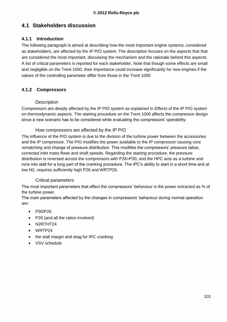
© 2012 Rolls-Royce plc
101
4.1 Stakeholders discussion
4.1.1 Introduction
The following paragraph is aimed at describing how the most important engine systems, considered
as stakeholders, are affected by the IP P/O system. The description focuses on the aspects that that
are considered the most important, discussing the mechanism and the rationale behind this aspects.
A list of critical parameters is reported for each stakeholder. Note that though some effects are small
and negligible on the Trent 1000, their importance could increase significantly for new engines if the
values of the controlling parameter differ from those in the Trent 1000
4.1.2 Compressors
Description
Compressors are deeply affected by the IP P/O system as explained in Effects of the IP P/O system
on thermodynamic aspects. The starting procedure on the Trent 1000 affects the compressor design
since a new scenario has to be considered while evaluating the compressors‟ operability.
How compressors are affected by the IP P/O
The influence of the P/O system is due to the division of the turbine power between the accessories
and the IP compressor. The P/O modifies the power available to the IP compressor causing core
rematching and change of pressure distribution. This modifies the compressors‟ pressure ratios,
corrected inlet mass flows and shaft speeds. Regarding the starting procedure, the pressure
distribution is reversed across the compressors with P26>P30, and the HPC acts as a turbine and
runs into stall for a long part of the cranking procedure. The IPC‟s ability to start in a short time and at
low N2, requires sufficiently high P26 and WRTP26.
Critical parameters
The most important parameters that affect the compressors‟ behaviour is the power extracted as % of
the turbine power.
The main parameters affected by the changes in compressors‟ behaviour during normal operation
are:
P30/P26
P26 (and all the ratios involved)
N2RTHT24
WRTP24
the stall margin and drag for IPC cranking
VSV schedule
© 2012 Rolls-Royce plc
102
4.1.3 Turbines
Description
Turbines are not directly affected by the P/O system in since HPT and IPT are usually choked during
the main part of the operational envelope, as explained in Effects of the IP P/O system on
thermodynamic aspects.
How Turbines are affected by the IP P/O system
The starting point to size a turbine is the specific power required based, on the aerodynamic
parameters which deliver the work at the required level of performance. If the required specific power
goes up due to power offtake load, the stage efficiency should drop for a heavily loaded stage,
requiring another stage and the redesign of the turbine.
An increase in P/O level from the IP shaft, affects the turbine also via variation of cooling and sealing
air characteristics. Considered are also effects of rematching and the effects of SAS on the IPT
blades cooling air.
No action has been taken to take into account changes of mechanical loads due to P/O level variation
or dynamic behaviour (e.g. STO): the P/O effect has been considered only as extra power to deliver
to the IP shaft over a certain range of conditions.
Critical parameters
The parameters affected by the presence of the IP P/O system are the same as those modified by a
larger compressor:
Annulus mean radius,
Blade tip to root ratio,
Blade number,
Blade speed.
The limiting parameters for the specific stage load level and thus for the shaft power are:
Flow turning angle within a single stage,
Peak Mn,
Diffusion rate on blade suction surface,
LPT inlet flow characteristics,
Stage load.
The critical parameters for the secondary air system are:
P44/P26,
P43/P27.
4.1.4 Air and Oil systems
Description
The P/O system changes the pressure distribution inside the engine, which affects bearing loads and
their clearances. The P/O system, in turn, can be affected by changes in air bleed temperature:
different working temperatures for gears and bearings can require modifications of the detailed design
© 2012 Rolls-Royce plc
103
and of the oil/air flows. If the temperature difference is significant then modification of the lubrication
system and heat-to-oil management could be required.
At low engine power levels, the SASV feeds the secondary air system with HP3 air, the same stage is
used over the whole engine operation to provide the air necessary to cool the IPT disk and blades.
When HP HBVs are commanded open (total of 4 bleeds from HP3: 2 HBVs, 1 SASV, and internal air
system bleed) up to the 10% of the core airflow can be extracted. If too much air is taken this can
reduce the stage pressure at HP3 and modify the pressure difference across the secondary air
system. On actual Trent 1000, there is not enough air bleed from HP3, so the small pressure variation
is likely to be harmless for the considered systems.
The IP P/O system has a particular effect on the sealing systems of all bearing chambers: increasing
P/O level increases bearing loads and reduces the buffer pressure. The first effect is a direct effect of
the larger forces between the gears‟ teeth, the second effect is a consequence of the PS26 drop
when the IP P/O level increases. This is exactly the opposite of what happens in an HP P/O engine,
where PS26 increases with the power extraction. The design condition to avoid that the source
pressure drops lower than sink pressure is where high power is extracted. The EDP for an HP P/O
engine is conducted with no P/O, i.e. the worst air system configuration. For the Trent 1000, to obtain
the worst condition; the power extraction has to be kept to the maximum.
Negative G acceleration has a negative effect on the engine since the oil system is based on gravity
effects, from the oil tank to scavenge and venting lines. When the gravity is reversed the scavenge
flow stops while the feeding system is still pumping oil inside the gearbox until the feed line is filled
with oil. Something similar happens also in the oil tank and the pump is no longer fed with oil but
starts pumping air into the oil system increasing the pressure in the bearing chambers.
The robustness of the oil system has to be checked against negative-G requirements which arise
from Airframer and Certification Agency. If the result of this assessment is negative, i.e. the oil system
is not able to operate at negative G and provide for this capability would result in an unacceptable
effort, mitigation has to be provided by the P/O system design. This can produce a requirement in
terms of operation (time and load) without lubricant and with non standard pressures in gearboxes
and bearing housings.
How Air and Oil systems are affected by the IP P/O system
Data removed
Critical parameters
The working characteristics of both compressors are important since air and oil system rely on P26
(IP8), P27 (HP3) and P30 (HP6). The oil pressure, oil massflow and HTO performance depend
directly on shaft speed. The oil pressure affects the oil sealing capability.
The impact of the P/O system on air and oil systems is through these pressures and shaft speed
changes. The most important but less evident features that are on the Trent 1000 (e.g. buffer
pressure and turbine rim seals) depend directly on this matter.
The main parameters affecting the Air system, which are related to the P/O system are:
1. Compressors‟ (HPC and IPC) delivery pressures
2. Secondary air system pressures
3. Secondary air system temperatures
© 2012 Rolls-Royce plc
104
4. Shaft speeds.
4.1.5 Transmission, Structures and Drives
Description
T, S & D are the Stakeholder responsible for the hardware design and integration of the Power
Offtake system. Increased power offtake capability of the drive train, decreased weight, minimized
windage are some aspects that have to be considered by the T, S & D department.
The mechanical problems of the P/O system are not directly related with taking the power from the IP
shaft instead of the HP, but are likely to depend on secondary effects of the two architectures and on
the accessories‟ control system, behaviour, and configuration.
The loads resulting from compressor deep surge are larger on the IP system than on the HP system;
the same observation can be made for the speed gradient: usually, after a deep surge, the IP shaft
speed is almost zero. The deceleration of the spool is huge and loads are very high since the inertia is
much bigger than in an HP P/O system. These loads are a design constraint since they cannot be
influenced or changed, and the mechanical system has to be able to withstand them. It is also
because of this that all problems related to resonance or natural frequencies don‟t constitute a threat
for the system integrity: the system is usually somehow “oversized”. The HP spool has a lower inertia
compared to the IP shaft, smaller speed variation during surge, a smaller speed range during normal
engine operation and smaller torque have to be transferred through the drivetrain.
The length of the Radial Drive Shaft (RDS) is usually set by the radial dimension of the fan air duct.
The Trent 1000 has a very high BPR, which requires a larger fan duct and a longer RDS. Another
issue that restricts the range of viable solutions is the necessity of allocating the bearings inside the
IGB considering lubrication, HTO, assemblability and effects on structure performance. Natural
frequencies of the drive train should not change very much from an HP to an IP P/O system. The
spool inertia of both HP and IP systems are so high that the elastic characteristics of the drive train
can have only a very small influence on their dynamic behaviour.
Mounting the P/O bevel gear on a stub secured to the IP shaft instead that directly on the IP shaft has
a beneficial effect from the mechanic prospective: a “bumper-like” system is created. This feature
decouples the oscillations of the two systems, i.e. the IP shaft with compressor/turbine and the P/O
drive train. The IP shaft is very thin compared to the much stiffer stub shaft and compressor drum,
and can be considered as a torsional spring with two masses at both ends. Because of this, the drive
train is only slightly affected by oscillations of the IP system.
The SAGB‟s radial dimension is a concern for the fan air duct because it can cause aerodynamic
interference. When attempting to reduce this dimension, new problems arise from the RDS since the
shaft‟s length becomes critical for the dynamic behaviour. This is all due to an aerodynamic
requirement. The minimum required distance between the splitter and the fan OGVs is fixed and the
splitter length is proportional to its width that, in turn, depends on the RDS outer diameter. The RDS
location bearing in the SAGB cannot be excessively moved towards the centre of the engine and
must provide a sufficiently rigid support for the shaft. During normal operation, the relative
displacement between the core fairings and the fan case ranges between X and Ymm. The drive train
© 2012 Rolls-Royce plc
105
has to be designed to tolerate this misalignment. This is a very stringent requirement in conjunction
with all the other characteristics required by the drivetrain: large misalignment in the barrel splines
under long time means a huge amount of heat produced inside the RDS assembly and larger gap
between the RDS and its case. Because of the increased amount of power extracted, and the
aforementioned lower speed and higher torque, the heat generated by friction or windage on the Trent
1000 is larger than on other Trent engines.
Another set of requirements for the AGB is related to maintainability and assemblability, which can
limit integration and new layouts for the accessories. This issue is common on IP and HP P/O
systems.
An important difference between IP and HP P/O system is the management ball bearing skidding for
the HP shaft. Historically the HP ball bearing in the IGB is exposed to aerodynamic and pressure
loads, from turbine/compressor interaction, and from mechanical loads (P/O drive train). The
aerodynamic loads at idle are very small and near to zero. The reason why this has been accepted on
other Trent engines is that a small mechanical load was always present in the HP P/O system,
preventing the bearing from skidding
How T, S & D are affected by the IP P/O system
The bevel gear that rotates with the IP shaft is not mounted directly on the torque-carrying section of
the IP shaft but on a stub, which is coupled with the IP ball bearing and then secured on the IP shaft
in order to reduce the gear teeth misalignment. Bringing the loads as close as possible to the bearing
in the IGB is an important requirement for the IP P/O system because the transferred torque is bigger
compared to an HP P/O system with the same power
With an IP P/O system, since the gears work at lower rotational speed but with a higher torque, the
teeth‟s width has to be increased in order to meet the life requirements. This affects the design of the
whole IGB area including
The bearing position and the gap between the last IP stage and the first HP stage
The radius of the IP8 blades roots.
Bearing design and size.
Critical parameters Power peaks during load transients caused by VFSG control system need to be considered by the
design of the IP P/O system to guarantee the drive train‟s life and mechanical integrity. There will be a
considerable amount of extra weight due to this requirement. A similar behaviour can be seen when a
brittle shear neck breaks: a very high load is impulsively removed, this create a “slingshot effect” that
is harmful for mechanical parts.
Transient overshoot factor,
STO frequency,
Minimum P/O load,
Maximum P/O load,
Loads related to accessory failure,
Loads related to shear neck failure,
IGB – SAGB displacement and misalignment,
IGB bevel gears axial movement,
IP shaft – AGB gear ratio,
© 2012 Rolls-Royce plc
106
RDS and ADS whirling constants,
4.1.6 FMECA
The Failure Mode Effects And Criticality Analysis, also known as FMECA, is the main tool to satisfy
the requirements of EASA Certification Specification (Engines CS-E 510 Safety Analysis) with respect
to the engine turbo-machinery. The Safety Analysis of the Engine Control System is excluded from
the scope of this procedure. A FMECA is produced for two main purposes:
1. To assist in the design process in order to identify and eliminate unsafe or unreliable designs
2. As part of a process to produce a Safety Analysis for product certification.
There are four main activities involved in producing a FMECA:
Identification and Design Understanding
Failure Mode and Effects Analysis
Criticality Analysis and Classification
Reporting and Feedback
The first point of the list is implicit to the first part of this report (
© 2012 Rolls-Royce plc
107
Summary
The progressive increase of power extracted from the engine for the electrical aircraft has
raised the issue of the competitive position of 2-shaft vs. 3-shaft engines and, within the
3-shaft architecture, the effects of using a different shaft to drive the accessory gearbox.
The aim of this report is to define the key parameters and features of an IP P/O system, how they
are influenced, what are the systems and stakeholders involved and, qualitatively, how they are
influenced. This is done in order to explain and better understand the decisions made during the
design and development of the T1000, why certain solutions have been selected and others rejected,
which areas of P/O design require particular attention and what are the lessons learnt.
The first part of this document is aimed at better understanding the theory and the rationale behind
the IP P/O system and its influences on the engine. In order to do this different topics are discussed,
starting from Load requirements, Idle setting, Engine weight, Fuel burn, Starting performance,
Thermodynamic and Mechanical aspects, Secondary air system features and Noise.
The second part is aimed at reviewing the design procedure using the Systems Thinking
approach, i.e. considering the P/O system not just as the sum of its components but as a system
with different properties, functions and effects. The review of the design process starts from the
Definition of Requirements, proceeds with the Stakeholders Analysis (only the most affected
are considered in detail) and ends with a review of the system on the actual engine (Trent 1000
Pack B): relation between requirements, functions and implementation, review of ERMS and
Lessons Learnt databases and FMECA report.
PART ONE – Understanding of the IP Power Offtake system). The most important activities
are the second and the third, while the fourth is used during the design and will not be reviewed here.
Failure mode and effects analysis
For each part of the engine, all potential failure mechanisms should be recorded. The resulting
System Failure Modes are entered into FMECA tables. For each System Failure Mode all possible
effects of the failure should be considered and recorded. The effects should be described at a system
level, at an engine level and at an aircraft level. The analyst needs to address any effects propagating
over interfaces. Consideration must be given to the continued safe flight and landing of the aircraft.
Criticality Analysis and Classification
For each failure, the effects need to be classified at Engine level. The categories are given in the
regulations. It is important that the severity classification reflects the failure effect exactly.
A judgement or estimation needs to be made concerning the rate at which each effect might occur.
This needs to be estimated based on whatever evidence or experience is available. Failure rate
bands are given in the regulations. Advice on failure classification and rate estimation is given in the
ALG section in the RRQMS (Rolls Royce Quality Management System). When a FMECA is used to
© 2012 Rolls-Royce plc
108
answer the requirements for Safety Analysis, that FMECA is executive in classification of Critical
Parts.
The FMECA should be developed throughout the design process. In stage 1 the FMECA should
concentrate on novel features of the design. Increase in detail should be added throughout stage 2. A
FMECA statement is required for each gate review
Before the engine development programme starts, an estimate of the likelihood of detection (in the
programme) should be made for each failure mode / effect. This combined with the severity and the
estimated rate of occurrence in service should be used to calculate a Risk Priority Number or RPN.
Failure modes / effects with large RPNs should be highlighted to the Engine Project for further
mitigation. A list of high risk items or list of items in RPN order should be produced.
Full FMECA System/Functional FMECA and, subsequently, part FMECA detailing all
failure mechanisms, propagations and consequences. The first issue should
be available before first engine test bed run.
Summary FMECA Summary of all Major and Hazardous Effects is normally a document used for
certification and therefore has to be agreed by the Certifying Authority. The
first issue is required for Engine Certification. Includes assumptions about the
aircraft and its operation, maintenance and instrumentation.
Within the present report the Summary FMECA performed for the Trent 1000 Pack B engines has
been reviewed to underline the main features related to the presence of the IP power offtake system.
As underlined in the previous paragraphs, from the engine prospective, the main differences between
HP and IP P/O system can arise from the following systems or components:
IGB;
Air System;
Oil system.
Data removed
© 2012 Rolls-Royce plc
109
4.2 Requirements – Functions correlation
In this paragraph, the functional requirements will be checked against the implementation solutions
that have been adopted on the Trent 1000. A short summary of the lessons learnt from each solution
is reported in the last column.
The information reported in the following table has been obtained from interviews with senior
engineers working in the Trent 1000 programme. Technical reports and from the Lessons Learnt Log
on the R-R Intranet Capability website have also been used as data source. For a proper design of
the drive train, in addition to the aforementioned recommendations, all the lessons learnt listed in
“Definition checklist for Gearboxes”, DNS 131800, C. Childs must be considered.
Data removed
4.3 ERMS report
The acronym ERMS stands for Event Recording and Monitoring System. An essential element of a
development process for all projects is the recording of significant events during engine build, test and
strip that may have implications for the reliability of in-service engines. These events must be formally
considered for corrective action and a database maintained giving traceability of what action has been
carried out. This process is a subset of the total workflow needed to completely define a new or
modified Rolls-Royce product within the context of Create customer solutions. In order to maintain the
coherency of the safety and reliability process the entire product lifecycle is covered. The ERMS
process should run through the entire Engine Development Programme until Entry Into Service, at
which point all problems should be raised and dealt with via the Resolve Customer Issues process.
At EIS+2 years the ERMS database should be closed and archived. At EIS all open ERMS events
should be addressed and driven towards closure by EIS+2. At EIS+2 all residual ERMS events should
be migrated to the RCI process to allow formal closure of the ERMS database and archiving of the
data.
An ERMS event is defined as an event during build, test or strip of development engines or
components which would be considered undesirable on a production or service basis and which
represents a potential reliability concern
A Category assigned to an event denoted by a letter that indicates a level
of reliability according to likely effects that fault/failure may produce.
4.3.1 ERMS Reliability categories
These categories are used to classify the impact of the arisen/detected problem on engine
performance and to express the severity of its consequences. They range from major issue that can
result in a safety concern to minor issues that have no effects on operability or reliability of the engine.
A Events that could have directly or indirectly cause an IFSD
B Events where the commanded thrust is not achieved or
© 2012 Rolls-Royce plc
110
uncommanded thrust changes are observed.
C Events where the in-flight restart capability is degraded.
D Events which could result in an unscheduled engine removal.
E Events which could cause serious service disruption in terms of
delays, cancellations or diversions
F Loss of dual lane redundancy of the FADEC system
X Other, non-ETOPS affecting events. These may be further sub-
divided as given below as X1 or X2.
X1 Non-ETOPS Customer irritant
X2 Non-ETOPS
4.3.2 ERMS Status Categories
Investigate The Event is still being looked into by the Problem Owner.
Repeat An event with the same root cause as an existing event on the database
Problem Report/A-Sheet Following the investigation, a design solution has been requested.
Hold Although the Event has been investigated, there is no clear understanding of
how to address it, and unless there is a recurrence, or additional evidence from
elsewhere, the Event cannot be taken any further.
Reject The Event has been rejected. No further updates are required.
Ex-committee An event that can be closed/rejected etc. when the appropriate out of meeting
action has been carried out.
Closed The Event has been understood and addressed, and the solution proven, if
applicable (PCB 3 or 4, as agreed within the project, dependent upon
modification incorporation policy. Refer to GQP C.1.4).
In addition, there is a temporary status of 'Undecided' that can be applied to new Events before they
are discussed at the Committee Meeting and given a status.
4.3.3 Trent 1000 ERMS log
The analysis of the Trent1000 ERMS was focused on capturing those elements related with the
Power Offtake hardware. Investigate the issues that are plausibly related to the IP P/O system is likely
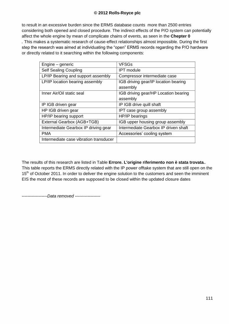
© 2012 Rolls-Royce plc
111
to result in an excessive burden since the ERMS database counts more than 2500 entries
considering both opened and closed procedure. The indirect effects of the P/O system can potentially
affect the whole engine by mean of complicate chains of events, as seen in the Chepter 0
. This makes a systematic research of cause-effect relationships almost impossible. During the first
step the research was aimed at individuating the “open” ERMS records regarding the P/O hardware
or directly related to it searching within the following components:
Engine – generic VFSGs
Self Sealing Coupling IPT module
LP/IP Bearing and support assembly Compressor intermediate case
LP/IP location bearing assembly IGB driving gear/IP location bearing
assembly
Inner Air/Oil static seal IGB driving gear/HP Location bearing
assembly
IP IGB driven gear IP IGB drive quill shaft
HP IGB driven gear IPT case group assembly
HP/IP bearing support HP/IP bearings
External Gearbox (AGB+TGB) IGB upper housing group assembly
Intermediate Gearbox IP driving gear Intermediate Gearbox IP driven shaft
PMA Accessories‟ cooling system
Intermediate case vibration transducer
The results of this research are listed in Table Errore. L'origine riferimento non è stata trovata..
This table reports the ERMS directly related with the IP power offtake system that are still open on the
15th of October 2011. In order to deliver the engine solution to the customers and seen the imminent
EIS the most of these records are supposed to be closed within the updated closure dates
------------------Data removed ------------------
© 2012 Rolls-Royce plc
112
4.4 Lessons Learnt Log
-----------------Data removed----------------------
5 APPENDIX 1 – IDLE CONTROL PARAMETERS
On the Trent family the idle schedules are based on (Ref. 1):
o Minimum T20/288.15
N3 i.e. HP reduced rotation speed, primary schedule used to define Low
Idle and High Idle. Also ensures HP electrical generators do not drop offline on Trent 700,
Trent 800, Trent 500, Trent 900
o Minimum N1 – Ensures the IP Compressor inlet conditions are aligned with those
demonstrated during the Certification icing tests, for all Trent engines,
o Minimum T30 – Avoids presence of liquid water at combustor inlet conditions, for all Trent
engines
o Minimum P30 – Ensures cabin bleed pressure requirements are met (Trent 700, Trent 800,
Trent 500, Trent 900) and protects combustor stability, for all Trent engines
o Minimum Fuel Flow / P30 – Protects the engine lean stability limit by ensuring operation with
healthy levels of Air-to-Fuel ratio, for all Trent engines.
o Minimum PS26 – Protects Air/Oil system by sealing the Front Bearing Housing to prevent oil
leaks and ensure enough HP Compressor drum flow. Also protects HP Compressor stability at
the top left hand corner of the envelope on Trent 1000 only,
o Minimum corrected NMix – Avoids excessive thrust asymmetry during slam acceleration
manoeuvres and is the primary schedule used to define Low Idle and High Idle, only on the
Trent 1000,
o Minimum N2 – Ensures the electrical generators do not drop offline, on the Trent 1000 only,
The idle schedule is controlled only by some of the aforementioned parameters. The remaining
quantities are extracted as function of the controlling variables. NMix is a measure of the core shaft
speed and depends on the angular momentum of the IP and HP spools. Since this parameter is
very
1
2
3
2
2
K
NNKNMix (%)
Where: .N 100%
N 100%2
3
2 constJ
JK
HP
IP
N2= IP Shaft Speed (%)
N3= HP Shaft Speed (%)
JI = IP Spool Inertia (lb.ft2)
© 2012 Rolls-Royce plc
113
JH = HP Spool axial Inertia (lb.ft2)
100% N3 = 100% HP Shaft Speed (rpm)
100% N2 = 100% IP Shaft Speed, (rpm)
Note that K~1.289 for Trent 1000 (Ref. 12). NmixDot is the time derivate of NMix and is used as the
acceleration control feedback parameter and the set point is taken from a schedule versus Nmix . The
ACU (Acceleration Control Unit) parameters are:
696.14/20 NMDTDP20P
NMixDot Vs.
15.288/20 NMRTHT20
T
NMix
Where:
P24: Engine Inlet Total Pressure (psi)
T24: Engine Inlet Total Temperature (K)
Increasing IPT size to lower the IPC working line (and PR at idle), as a mean to reduce idle thrust and
fuel burn needs to be checked against the requirements for the IP P/O system. Advantages gained
lowering the IPC operating point are counterbalanced by the need for a higher speed for the IP/HP
shaft (
Ref. 41, Ref. 42).

© 2012 Rolls-Royce plc
114
6 APPENDIX 2 – SYS-ML MODEL OF THE IP P/O SYSTEM
6.1 SysML language
The Systems Modelling Language (SysML) is a general-purpose modelling language for systems
engineering applications. It supports the specification, analysis, design, verification and validation
of a broad range of systems and systems-of-systems.
Systems Engineering (SE) relies on modelling and simulation methods to validate requirements or
to evaluate the system. Therefore modelling is common practice in SE to deliver functional
specifications, data flow description, or system structure definitions through the use of modelling
techniques such as:
Data Flow Diagram (DFD) to define the data going through a system, and any processing
required
Functional Flow Block Diagram (FFBD), similar to the UML6 activity diagram
Specifications produced with SE often result from a document-based approach, producing a large
amount of documents with various types of diagrams or notations, sometimes used in an
inconsistent manner.
SysML offers the alternative of using a model-based approach, usually referred as the “Model-
Based Systems Engineering”, to deliver a consistent set of system views, stored and managed in a
repository. Modelling the system in such a way helps to manage complexity and avoid ambiguities
or discrepancies since each element that constitutes the system can be defined only once and
then used in different diagrams.
SysML defines the following diagrams:
The requirements diagrams
Structure diagrams
o The Block Definition Diagram (BDD)
o The Internal Block Diagram (IBD)
o The Parametric Diagram,
o The Package Diagram
Dynamic diagrams
o The activity diagram
o The sequence, state chart, and use case diagrams
Only some types of diagram have been produced for the IP P/O system. They are reported in the
next paragraphs alongside a short description of their content.
6.2 Requirements
Systems Engineering uses requirements to formalize the stakeholders‟ needs, which will be
realized as functionality and constraints, satisfied by the delivered application or system. In order to
6 Forerunner of the SysML language
© 2012 Rolls-Royce plc
115
create a consistent set of requirements the procedure described in Par.3.2 can be used, this set
may then be organized using SysML. A model based approach makes use of requirements
through dependency associations with elements from the model such as use cases, blocks, or test
cases, establishing the model traceability.
6.3 Block Definition Diagram (BDD)
The BDD is a kind of “bill of sub-system” or components that constitutes the IP P/O system. It
provides a black box representation of the hardware.
6.4 Internal Block Diagram (IBD)
The Internal Block Diagram or IBD provides the white box or internal view of a system block, and is
usually derived from the Block Definition Diagram (BDD) to represent the final assembly of all
blocks within the main system block. Composite blocks from the BDD are instantiated on the IBD
as parts. These parts are assembled through connectors, linking them directly or via their ports
(standard ports with exposed interfaces and/or flow ports).
6.5 Activity diagram
The Activity Diagram represents steps of a process, often making use of “input and output pins”
that respectively correspond to the element type required as the input of an activity or action, and
the element generated as an output. If an action or activity corresponds to a block operation, it is
possible to ensure that the types of the input and output of this activity are consistent with the block
operation signature.
6.6 Use case diagrams
A Use Case Diagram can be used to describe the functionality of a system in a horizontal way.
That is, rather than merely representing the details of individual features of your system, UCDs can
be used to show all of its available functionality. It is important to note, though, that UCDs are
fundamentally different from sequence diagrams or flow charts because they do not make any
attempt to represent the order or number of times that the systems actions and sub-actions should
be executed. The use case diagram usually relies on a Use Case Analysis, for the Trent 1000 IP
P/O system this diagrams are obtained starting from the Viewpoint Analysis carried out during the
requirements elicitation process. A use case diagram can represent the system and the actors
from a top-level point, showing just a link between the parts, or it can show what are the quantities
involved into the aforementioned interaction.
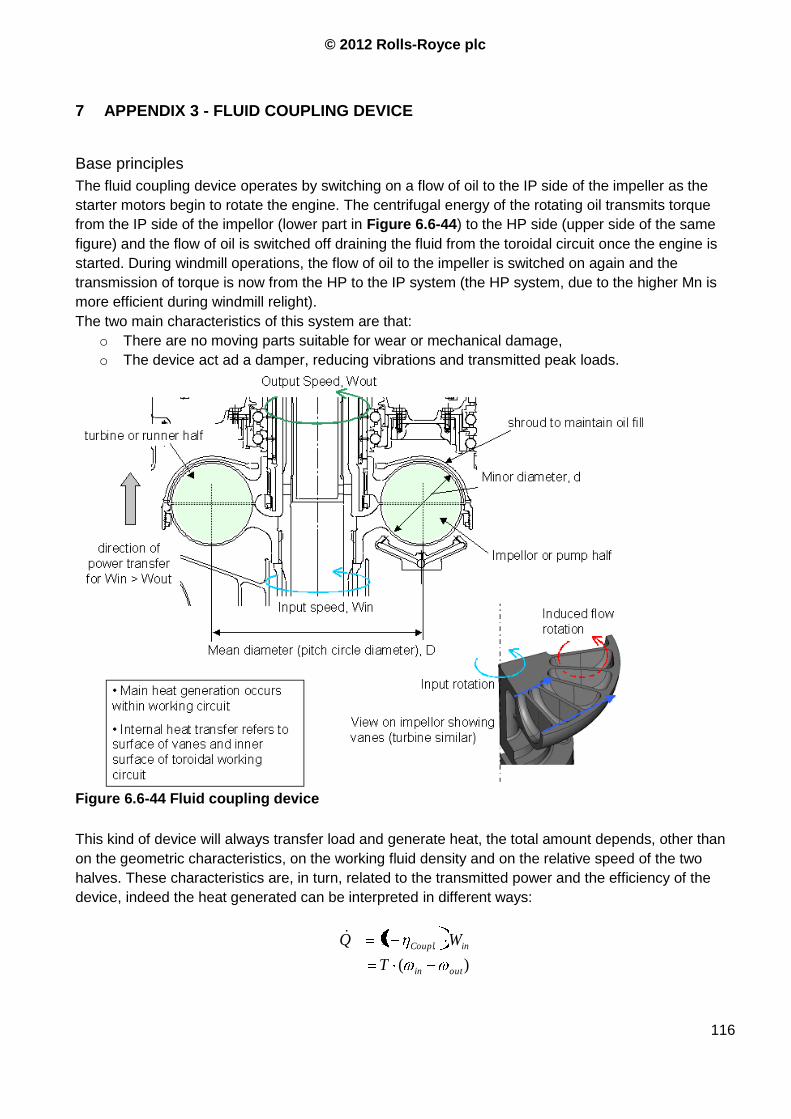
© 2012 Rolls-Royce plc
116
7 APPENDIX 3 - FLUID COUPLING DEVICE
Base principles
The fluid coupling device operates by switching on a flow of oil to the IP side of the impeller as the
starter motors begin to rotate the engine. The centrifugal energy of the rotating oil transmits torque
from the IP side of the impellor (lower part in Figure 6.6-44) to the HP side (upper side of the same
figure) and the flow of oil is switched off draining the fluid from the toroidal circuit once the engine is
started. During windmill operations, the flow of oil to the impeller is switched on again and the
transmission of torque is now from the HP to the IP system (the HP system, due to the higher Mn is
more efficient during windmill relight).
The two main characteristics of this system are that:
o There are no moving parts suitable for wear or mechanical damage,
o The device act ad a damper, reducing vibrations and transmitted peak loads.
Figure 6.6-44 Fluid coupling device
This kind of device will always transfer load and generate heat, the total amount depends, other than
on the geometric characteristics, on the working fluid density and on the relative speed of the two
halves. These characteristics are, in turn, related to the transmitted power and the efficiency of the
device, indeed the heat generated can be interpreted in different ways:
)(
1 .
outin
inCoupl
T
WQ

© 2012 Rolls-Royce plc
117
Where: Coupl
is the coupling device efficiency,
inW is the inlet power
T is the torque, equal between in and out
in and out are the inlet and outlet rotation speeds.
Since the torque is constant among the two shafts the power transmitted and that lost will be a
function of the relative speed outin as stated above.
Now is possible to define a series of non-dimensional parameters:
Speed ratio 1in
outSR
Slip Factor SRSin
outin 1
Torque coefficient: 52 D
TC
inM
Where: D is a characteristic dimension of the coupling device, assumed being
the PCD (Pitch Circular Diameter)
is the density of the working fluid
It can easily be seen as SRW
W
in
out being T=const.
Using the aforementioned parameters the rate of heat generated by the fluid clutch can be written as
)1(53 SRCDQ Min
This expression underlines the importance of some key parameters involved in heat generation, i.e.
power loss. These parameters are driving shaft speed and the coupling size D. the fluid density and
the slip factor are also present but with unitary exponent.
Using a 1-D model that does not consider the number of vanes can be obtained that:
----Data removed-----
Where: k is the internal flow loss coefficient, accounts for friction and
imperfections,
d is the internal diameter of the impellor
This model has been shown to be reasonably reliable by comparison with experimental data and CFD
analysis if the following set of input parameters is used (Ref. 8, Ref. 9):
o 4.0D
d
o 5.0
1 SRk if
15.0
5.00
SR
SR
o Approximately 20 vanes.
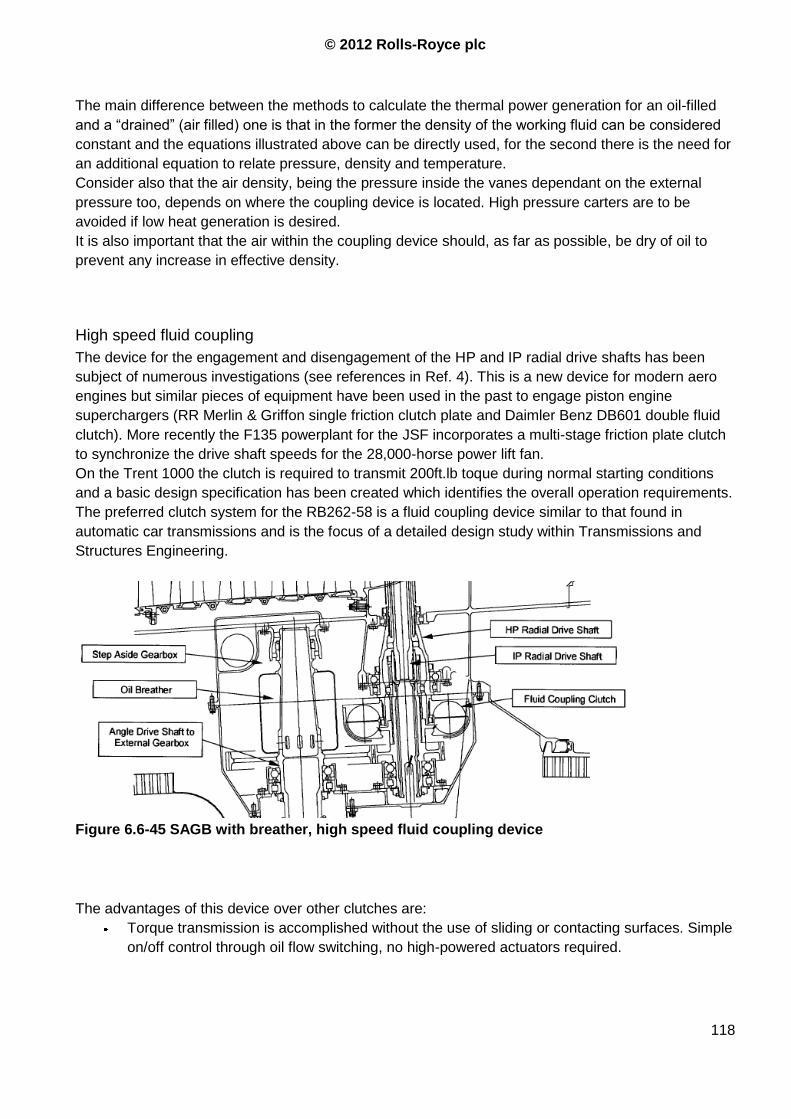
© 2012 Rolls-Royce plc
118
The main difference between the methods to calculate the thermal power generation for an oil-filled
and a “drained” (air filled) one is that in the former the density of the working fluid can be considered
constant and the equations illustrated above can be directly used, for the second there is the need for
an additional equation to relate pressure, density and temperature.
Consider also that the air density, being the pressure inside the vanes dependant on the external
pressure too, depends on where the coupling device is located. High pressure carters are to be
avoided if low heat generation is desired.
It is also important that the air within the coupling device should, as far as possible, be dry of oil to
prevent any increase in effective density.
High speed fluid coupling
The device for the engagement and disengagement of the HP and IP radial drive shafts has been
subject of numerous investigations (see references in Ref. 4). This is a new device for modern aero
engines but similar pieces of equipment have been used in the past to engage piston engine
superchargers (RR Merlin & Griffon single friction clutch plate and Daimler Benz DB601 double fluid
clutch). More recently the F135 powerplant for the JSF incorporates a multi-stage friction plate clutch
to synchronize the drive shaft speeds for the 28,000-horse power lift fan.
On the Trent 1000 the clutch is required to transmit 200ft.lb toque during normal starting conditions
and a basic design specification has been created which identifies the overall operation requirements.
The preferred clutch system for the RB262-58 is a fluid coupling device similar to that found in
automatic car transmissions and is the focus of a detailed design study within Transmissions and
Structures Engineering.
Figure 6.6-45 SAGB with breather, high speed fluid coupling device
The advantages of this device over other clutches are:
Torque transmission is accomplished without the use of sliding or contacting surfaces. Simple
on/off control through oil flow switching, no high-powered actuators required.
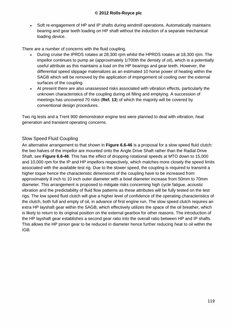
© 2012 Rolls-Royce plc
119
Soft re-engagement of HP and IP shafts during windmill operations. Automatically maintains
bearing and gear teeth loading on HP shaft without the induction of a separate mechanical
loading device.
There are a number of concerns with the fluid coupling.
During cruise the IPRDS rotates at 28,300 rpm whilst the HPRDS rotates at 18,300 rpm. The
impellor continues to pump air (approximately 1/700th the density of oil), which is a potentially
useful attribute as this maintains a load on the HP bearings and gear teeth. However, the
differential speed slippage materializes as an estimated 10 horse power of heating within the
SAGB which will be removed by the application of impingement oil cooling over the external
surfaces of the coupling.
At present there are also unassessed risks associated with vibration effects, particularly the
unknown characteristics of the coupling during oil filling and emptying. A succession of
meetings has uncovered 70 risks (Ref. 13) of which the majority will be covered by
conventional design procedures.
Two rig tests and a Trent 900 demonstrator engine test were planned to deal with vibration, heat
generation and transient operating concerns.
Slow Speed Fluid Coupling
An alternative arrangement to that shown in Figure 6.6-46 is a proposal for a slow speed fluid clutch:
the two halves of the impellor are mounted onto the Angle Drive Shaft rather than the Radial Drive
Shaft, see Figure 6.6-46. This has the effect of dropping rotational speeds at MTO down to 15,000
and 10,000 rpm for the IP and HP impellors respectively, which matches more closely the speed limits
associated with the available test rig. Due to the slower speed, the coupling is required to transmit a
higher toque hence the characteristic dimensions of the coupling have to be increased from
approximately 8 inch to 10 inch outer diameter with a bowl diameter increase from 50mm to 70mm
diameter. This arrangement is proposed to mitigate risks concerning high cycle fatigue, acoustic
vibration and the predictability of fluid flow patterns as these attributes will be fully tested on the test
rigs. The low speed fluid clutch will give a higher level of confidence of the operating characteristics of
the clutch, both full and empty of oil, in advance of first engine run. The slow speed clutch requires an
extra HP layshaft gear within the SAGB, which effectively utilizes the space of the oil breather, which
is likely to return to its original position on the external gearbox for other reasons. The introduction of
the HP layshaft gear establishes a second gear ratio into the overall ratio between HP and IP shafts.
This allows the HP pinion gear to be reduced in diameter hence further reducing heat to oil within the
IGB.
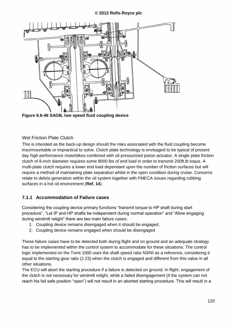
© 2012 Rolls-Royce plc
120
Figure 6.6-46 SAGB, low speed fluid coupling device
Wet Friction Plate Clutch
This is intended as the back-up design should the risks associated with the fluid coupling become
insurmountable or impractical to solve. Clutch plate technology is envisaged to be typical of present
day high performance motorbikes combined with oil pressurized piston actuator. A single plate friction
clutch of 8-inch diameter requires some 8000 lbs of end load in order to transmit 200ft.lb toque. A
multi-plate clutch requires a lower end load dependant upon the number of friction surfaces but will
require a method of maintaining plate separation whilst in the open condition during cruise. Concerns
relate to debris generation within the oil system together with FMECA issues regarding rubbing
surfaces in a hot oil environment (Ref. 14).
7.1.1 Accommodation of Failure cases
Considering the coupling device primary functions “transmit torque to HP shaft during start
procedure”, “Let IP and HP shafts be independent during normal operation” and “Allow engaging
during windmill relight” there are two main failure cases:
1. Coupling device remains disengaged when it should be engaged,
2. Coupling device remains engaged when should be disengaged
These failure cases have to be detected both during flight and on ground and an adequate strategy
has to be implemented within the control system to accommodate for these situations. The control
logic implemented on the Trent 1000 uses the shaft speed ratio N3/NI as a reference, considering it
equal to the starting gear ratio (2.23) when the clutch is engaged and different from this value in all
other situations.
The ECU will abort the starting procedure if a failure is detected on ground. In flight, engagement of
the clutch is not necessary for windmill relight, while a failed disengagement (if the system can not
reach his fail safe position “open”) will not result in an aborted starting procedure. This will result in a

© 2012 Rolls-Royce plc
121
progressive deterioration of the coupling system until it burns, the heat released would not threaten
the engine integrity but could damage the SAGB.
7.1.2 Additional requirements for coupling devices
1. Consider power required to engage and control the coupling system
2. Consider heat generated by the coupling device when in “disengaged position”
3. Vibration effects on the system:
a. Disengaged
b. Engaged
c. Engaging transiently (filling the oil coupling device)
4. For multiple disk clutch provide a device that separates the disks when the clutch is not
engaged.
5. Accommodate for fail close / fail open and consequences on the component and on the
engine.
© 2012 Rolls-Royce plc
122
References
Ref. 1 D715Z004-01 Specification for Trent 1000 Commercial Turbofan Engine on 787 Aircraft
Ref. 2 Boeing 7E7 / Rolls Royce Coordination memo 04-40-6001; rev. BA2; Oct. 2004
Ref. 3 “Power offtake effects on Multi-spool Gas Turbine Engines”; Arthur Rowe
Ref. 4 “Rb262-58 (Trent 1000) HP/IP P/O drive system – Concept design Report”; Alan Maguire;
Technical report-TIA42553.
Ref. 5 “Starting of three shaft aero engines by IP drive”, J. Towe, Technical report – PDR95040.
Ref. 6 “IP starting – The Ansty experience and implications for aero engine starting”; A. Rowe;
Technical report - PTR90627
Ref. 7 “Trent 1000 TGT ground starting”; D. Elysee; CE Highspots 13/07/2011
Ref. 8 “ An Approximate Model for the Characteristics of a Fluid Coupling”; N. Fomison; FSG
49039; Iss. 2, Jan 2005
Ref. 9 “ A CFD Investigation of Fluid Flow and Heat Transfer in a Fluid Coupling”; Z. Sun;
Thermo-Fluids UTC Report TFSUTC/2004/4, May 2004.
Ref. 10 “Trent 1000 - Package B VSV Schedule Development and Performance Effect Of
Production Schedule”; Dave Brown; PTR109906; June 2010
Ref. 11 “Trent 1000 – Idle Performance”; M. Pons Perez, Technical report - PTR109631
Ref. 12 “Trent 1000 Ground Idle Performance Requirements for Controls”; Peter Gillard;
Technical report PTR 109018
Ref. 13 “IP Power offtake presentation pack April 2004”; R. Clough and A. Swift.
Ref. 14 “Trent 7E7 HP-IP Coupling Design Rationale version 3”; D. Knott; Technical report.
Ref. 15 “IP power offtake on Trent 1700”; presentation pack.
Ref. 16 “Trent 1700 trade study – IP Vs. HP P/O”; C. Fouche M. Roquelle; Technical report – TIA442901. Ref. 17 “Functional Operability Starting Strategy on Trent 1000”; D.T.Hayes ; DNS 154945 Ref. 18 “Trent 1000 IPC stability audit prior to IPC aero rig test and first engine run”; B. Zewde; Technical report – PTR109049 Ref. 19 “Trent 1000 Performance requirements for control – Handling Bleed Valves for M2.0
cert software and Secondary Air System Bleed Logic”; B. Zewde, Technical report – PTR 109026
Ref. 20 “R-R Trent XWB Power offtake and speed range status”; Stephane Demoulin; Airbus
presentation pack.
Ref. 21 “Trent 1000 HPC stability audit – First Flight Readiness”; M. Dann; Technical report –
PTR109402
Ref. 22 “Trent 1000 IPC stability audit post IPC aero rig 823/1”; B. Zewde; Technical report – TIA
455307
Ref. 23 “A350 Trent XWB Power-off-Take”; N. Feuillard J.L.Rivot; Technical report (Airbus).
Ref. 24 “Trent 1000 ESS Anti-icing system worst case design points”; B. Zewde; Technical
report - PTR 109009
Ref. 25 “Trent 1000 Engine Secondary Power Extraction” , N/A, Internal Memo
Ref. 26 “Horse power extraction limits Boeing 7E7 / Rolls-Royce coordination memo”; B. Kaku;
coordination memo 04-40-6001
Ref. 27 “Trent 1000 IP Power offtake concept for Boeing 787”; G. Knight; internal memo
Ref. 28 “Starter / Generator and Drive Train Dynamic Loading Characteristics”; D.Luxton;
Lessons learnt log; Source Reference: DEI 1183
Ref. 29 “Dynamic factors on stepped electrical loads”; M Mountney / D Scothern; Lessons learnt
log
© 2012 Rolls-Royce plc
123
Ref. 30 “High surge torques on IP driven power offtakes”; M Mountney / D Scothern; Lessons
learnt log
Ref. 31 “Transmission and structures, Gearboxes, Lesson 636”; Lesson Learnt log
Ref. 32 Capability Intranet – Fluid systems
Ref. 33 “Trent 1000, Sub Systems Requirements Document for the secondary air system”; C.
P. Gravett; Technical report - FSG49004.
Ref. 34 “Air System Familiarization”; Paul Ferra; Internal report
Ref. 35 “Guide to Transient Performance”; A. Rowe; Performance Engineers Guide
Ref. 36 “Gas turbine theory”; H. Cohen H. Saravanamuttoo; Prentice Hall ed.
Ref. 37 Capability Intranet - System engineering
Ref. 38 Rolls Royce Quality Management Process; Intranet Capability
Ref. 39 “Product systems Integration and System Engineering”; Tony Bell; 15/06/09 Internal
meeting on product system integration
Ref. 40 "Trent 1000 Summary of oil and fuel system development problems and solutions";
R.E.Leese; Technical report FSG49755; Oct. 2009
Ref. 41 “Trent 1000: Study of Turbine Capacity Design Space Including an Assessment of the
Influence of Post Engine 4/3 Analysis Factors”, D J Sherwood, PTR109429
Ref. 42 "IPT Capacity for IPC Operability", Paul Richardson, PTR109333
Ref. 43 "Bleed Valve Status for 787-8 Package B Noise Certification", E. Spalton, Rolls-Royce
ECM 10-00-7078 RR0
Ref. 44 "Summary FMECA for Trent 1000 Package B Engine Cooling Air System", M. Krohn,
DNS 156082
Ref. 45 "Summary FMECA for Trent 1000 Package B. External Gearbox", P. Russel, DNS 156086
Ref. 46 "Summary FMECA for Trent 1000 Package B Intercase and Internal Gearbox", S.
Morton, DNS 156118
Ref. 47 "Summary FMECA for Trent 1000 Package B. Step-Aside Gearbox." P. Russel, DNS
157135
Ref. 48 “Trent 1000 Performance requirements for control – Handling Bleed Valves for M2.0
cert software, M2.2.2 flight software and Secondary Air System Bleed Logic”, Braky Zewde,
PTR109026 & PTR109235, Jul 2007
Ref. 49 “Trent 1000 - Package B VSV Schedule Development and Performance Effect Of
Production Schedule”, Dave Brown, PTR109906, June 2010
Ref. 50 “Trent 1000 Performance Requirements for Control – VSV ATF Software M1.0.1”; Mark
Stockwell, PTR 109039, Dec.2005
Ref. 51 “Trent 1000 performance requirements for controls –SASV fault detection and
accommodation”; Marc Pons Perez; PTR 109059; March 2009
Ref. 52 “Trent 1000 – Acceptability of Bleed Valves Delivered for Flight Compliance
Programme”; D Hulme; PTR 109627; Apr 2009