Ecology: MCAS Questions MCAS Questions from Before and Including the 2010 Test.


Facility Repairs MCAS Cherry Point - Tank Farm C WON6444311
PROJECT TABLE OF CONTENTS
DIVISION 00 - PROCUREMENT AND CONTRACTING REQUIREMENTS
00 01 15 LIST OF DRAWINGS00 22 13.00 20 SUPPLEMENTARY INSTRUCTIONS TO OFFERORS
DIVISION 01 - GENERAL REQUIREMENTS
01 11 00 SUMMARY OF WORK01 14 00 WORK RESTRICTIONS01 20 00.00 20 PRICE AND PAYMENT PROCEDURES01 30 00 ADMINISTRATIVE REQUIREMENTS01 33 00 SUBMITTAL PROCEDURES01 35 26 GOVERNMENTAL SAFETY REQUIREMENTS01 45 00.00 20 QUALITY CONTROL01 50 00 TEMPORARY CONSTRUCTION FACILITIES AND CONTROLS01 57 19 TEMPORARY ENVIRONMENTAL CONTROLS01 62 35 RECYCLED/RECOVERED/BIOBASED MATERIALS01 74 19 CONSTRUCTION AND DEMOLITION WASTE MANAGEMENT01 78 00 CLOSEOUT SUBMITTALS01 78 23 OPERATION AND MAINTENANCE DATA01 78 30.00 22 GIS DATA DELIVERABLES
DIVISION 02 - EXISTING CONDITIONS
02 41 00 DEMOLITION02 65 00 UNDERGROUND STORAGE TANK REMOVAL02 81 00 TRANSPORTATION AND DISPOSAL OF HAZARDOUS MATERIALS02 82 16.00 20 ENGINEERING CONTROL OF ASBESTOS CONTAINING MATERIALS02 83 13.00 20 LEAD IN CONSTRUCTION
DIVISION 03 - CONCRETE
03 01 30.71 CONCRETE REHABILITATION03 30 00 CAST-IN-PLACE CONCRETE
DIVISION 05 - METALS
05 50 13 MISCELLANEOUS METAL FABRICATIONS
DIVISION 09 - FINISHES
09 97 13.00 40 STEEL COATINGS09 97 13.27 EXTERIOR COATING OF STEEL STRUCTURES
DIVISION 22 - PLUMBING
22 00 00 PLUMBING, GENERAL PURPOSE
DIVISION 26 - ELECTRICAL
26 00 00.00 20 BASIC ELECTRICAL MATERIALS AND METHODS26 08 00 APPARATUS INSPECTION AND TESTING26 20 00 INTERIOR DISTRIBUTION SYSTEM26 32 13.00 20 SINGLE OPERATION GENERATOR SETS26 36 23.00 20 AUTOMATIC TRANSFER SWITCHES26 41 00 LIGHTNING PROTECTION SYSTEM
PROJECT TABLE OF CONTENTS Page 1
Facility Repairs MCAS Cherry Point - Tank Farm C WON6444311
DIVISION 27 - COMMUNICATIONS
27 10 00 BUILDING TELECOMMUNICATIONS CABLING SYSTEM
DIVISION 28 - ELECTRONIC SAFETY AND SECURITY
28 10 05 ELECTRONIC SECURITY SYSTEMS (ESS)
DIVISION 31 - EARTHWORK
31 11 00 CLEARING AND GRUBBING31 23 00.00 20 EXCAVATION AND FILL
DIVISION 32 - EXTERIOR IMPROVEMENTS
32 01 19.61 RESEALING OF JOINTS IN RIGID PAVEMENT32 01 29.61 PARTIAL DEPTH PATCHING OF RIGID PAVING32 11 23 AGGREGATE AND/OR GRADED-CRUSHED AGGREGATE BASE COURSE32 12 10 BITUMINOUS TACK AND PRIME COATS32 12 17 HOT MIX BITUMINOUS PAVEMENT32 13 13.06 PORTLAND CEMENT CONCRETE PAVEMENT FOR ROADS AND SITE
FACILITIES32 31 13 CHAIN LINK FENCES AND GATES
DIVISION 33 - UTILITIES
33 08 55 COMMISSIONING OF FUEL FACILITY SYSTEMS33 11 00 WATER UTILITY DISTRIBUTION PIPING33 40 00 STORM DRAINAGE UTILITIES33 52 43.13 FUEL PIPING33 52 80 LIQUID FUELS PIPELINE COATING SYSTEMS33 52 90.00 20 WELDING FOR POL SERVICE PIPING33 56 10 FACTORY-FABRICATED FUEL STORAGE TANKS33 57 00 FUEL RECEIVING/DISPENSING EQUIPMENT33 65 00 CLEANING PETROLEUM STORAGE TANKS33 71 01 OVERHEAD TRANSMISSION AND DISTRIBUTION33 71 02 UNDERGROUND ELECTRICAL DISTRIBUTION
-- End of Project Table of Contents --
PROJECT TABLE OF CONTENTS Page 2

Facility Repairs MCAS Cherry Point - Tank Farm C WON6444311
DOCUMENT 00 01 15
LIST OF DRAWINGS02/11
PART 1 GENERAL
1.1 SUMMARY
This section lists the drawings for the project pursuant to contract clause "DFARS 252.236-7001, Contract Drawings, Maps and Specifications."
1.2 CONTRACT DRAWINGS
Contract drawings are as follows:
SHEET NAVFAC NO DRAWING DRAWING NUMBER TITLEGENERAL 1 12757117 G-001 TITLE SHEET2 12757118 G-002 INDEX OF DRAWINGS, NOTES AND SYMBOLS3 12757119 G-003 TANK FARM 'C' HAUL ROUTE AND CONTROL POINTSDEMOLITION 4 12757120 D-101 SITE PLAN - TANK FARM 'C' DEMOLITION5 12757121 D-901 DEMOLITION PHOTOSCIVIL 6 12757122 C-001 CIVIL ABBREVIATIONS, LEGEND, AND NOTES7 12757123 C-101 SITE PLAN - TANK FARM 'C'8 12757124 C-501 CIVIL DETAILS9 12757125 C-502 CIVIL DETAILS10 12757126 C-503 CIVIL DETAILS11 12757127 C-504 EROSION AND SEDIMENT CONTROLSTRUCTURAL 12 12757128 S-001 STRUCTURAL ABBREVIATIONS, LEGEND, AND NOTES13 12757129 S-401 MISC STRUCTURES14 12757130 S-402 MISC STRUCTURES15 12757131 S-501 DETAILSMECHANICAL 16 12757132 M-001 MECHANICAL ABBREVIATIONS, LEGEND, AND NOTES17 12757133 M-101 SITE PLAN - TANK FARM 'C'18 12757134 M-401 PARTIAL PLAN19 12757135 M-501 MECHANICAL PIPING DETAILS20 12757136 M-502 MISCELLANEOUS DETAILS21 12757137 M-601 PIPING SCHEMATICSELECTRICAL 22 12757138 E-001 ELECTRICAL ABBREVIATIONS, LEGEND, AND NOTES23 12757139 E-101 SITE PLAN - TANK FARM 'C'24 12757140 E-401 PARTIAL PLAN - TANK FARM 'C' 124425 12757141 E-402 GROUND PRODUCTS CANOPY LIGHTNING PROTECTION26 12757142 E-403 PARTIAL PLAN - ABOVEGROUND TANKS27 12757143 E-501 ELECTRICAL DETAILS28 12757144 E-601 PANEL SCHEDULE TANK FARM 'C' 124429 12757145 E-701 ELECTRICAL PLATES30 12757146 E-702 HAZARDOUS AREA CLASSIFICATIONS
DOCUMENT 00 01 15 Page 1

Facility Repairs MCAS Cherry Point - Tank Farm C WON6444311
-- End of Document --
DOCUMENT 00 01 15 Page 2

Facility Repairs MCAS Cherry Point - Tank Farm C WON6444311
DOCUMENT 00 22 13.00 20
SUPPLEMENTARY INSTRUCTIONS TO OFFERORS02/14
PART 1 GENERAL
1.1 CONTRACT LINE ITEMS
The terms Offeror and Bidder and versions thereof (offer/bid) have the same definition as used within this contract.
Provide the Contract Line Item (CLIN) lump sum price for the following items:
CLIN 0 2 - BASE PRICE. Price includes the following:
CLIN DESCRIPTION TOTAL PRICE FOR CLIN
02-001A Price for the entire work to provide a new emergency generator and automatic transfer switch (Facility 4853G)at Filling Station Building 1244 in accordance with the drawings and specifications.
$__________
02-002A Price for the entire work to provide leak detection monitoring sensors at Filling Station 1899 in accordance with the drawings and specifications.
$__________
02-002B Price for the entire work to provide a permanent emergency eyewash and safety shower at Filling Station 1899 in accordance with the drawings and specifications.
$__________
02-002C Price for the entire work to repair the fuel containment slab below the canopy at Filling Station 1899, in accordance with the drawings and specifications.
$__________
DOCUMENT 00 22 13.00 20 Page 1

Facility Repairs MCAS Cherry Point - Tank Farm C WON6444311
CLIN DESCRIPTION TOTAL PRICE FOR CLIN
02-002D Price for the entire work to replace concrete joint sealant as required at Filling Station 1899 in accordance with the drawings and specifications.
$__________
02-002E Price for the entire work to paint concrete islands, steel rims and the protective bollards at Filling Station 1899 in accordance with the drawings and specifications.
$__________
02-003A Price for the entire work to provide leak detection monitoring sensor for the existing dispenser at Mogas AST/Fuel Pump Station 4802 (converted from E85 use)in accordance with the drawings and specifications.
$__________
02-003B Price for the entire work to properly ground the Mogas Tank Facility 4802 (converted from E85 use) in accordance with the drawings and specifications.
$__________
02-003C Price for the entire work to paint the supports, grating, guard rails, access ladder and all braces for the Mogas Tank Facility 4802 (converted from E85 use) in accordance with the specifications and drawings.
$__________
02-003D Price for the entire work to provide a conservation vent for Mogas Tank Facility 4802 (converted from E85 use) in accordance with the drawings and specifications.
$__________
DOCUMENT 00 22 13.00 20 Page 2

Facility Repairs MCAS Cherry Point - Tank Farm C WON6444311
CLIN DESCRIPTION TOTAL PRICE FOR CLIN
02-003E Price for the entire work to replace the brass and aluminum at Mogas AST/Fuel Pump Station 4802 (converted from E85 use)in accordance with the drawings and specifications.
$__________
02-003F Price for the entire work to repair the weeping unions at Mogas AST/Fuel Pump Station 4802 (converted from E85 use)in accordance with the drawings and specifications.
$__________
02-003G Price for the entire work to provide new gaskets and seals for the dispenser at Mogas AST/Fuel Pump Station 4802 (converted from E85 use)in accordance with the drawings and specifications.
$__________
02-003H Price for the entire work to demolish the existing mogas Tank 4899 and the associated monitoring wells and clean the existing E85 Tank for Mogas uses in accordance with the drawings and specifications.
$__________
02-004A Price for the entire work to provide new E85 Tank (Facility 200399) in accordance with the drawings and specifications.
$__________
02-005A Price for the entire work to replace the underground diesel storage tank and demolish associated monitoring wells at Facility 4900 with an aboveground diesel storage tank (Facility 200400)in accordance with the drawings and specifications.
$__________
DOCUMENT 00 22 13.00 20 Page 3
Facility Repairs MCAS Cherry Point - Tank Farm C WON6444311
CLIN DESCRIPTION TOTAL PRICE FOR CLIN
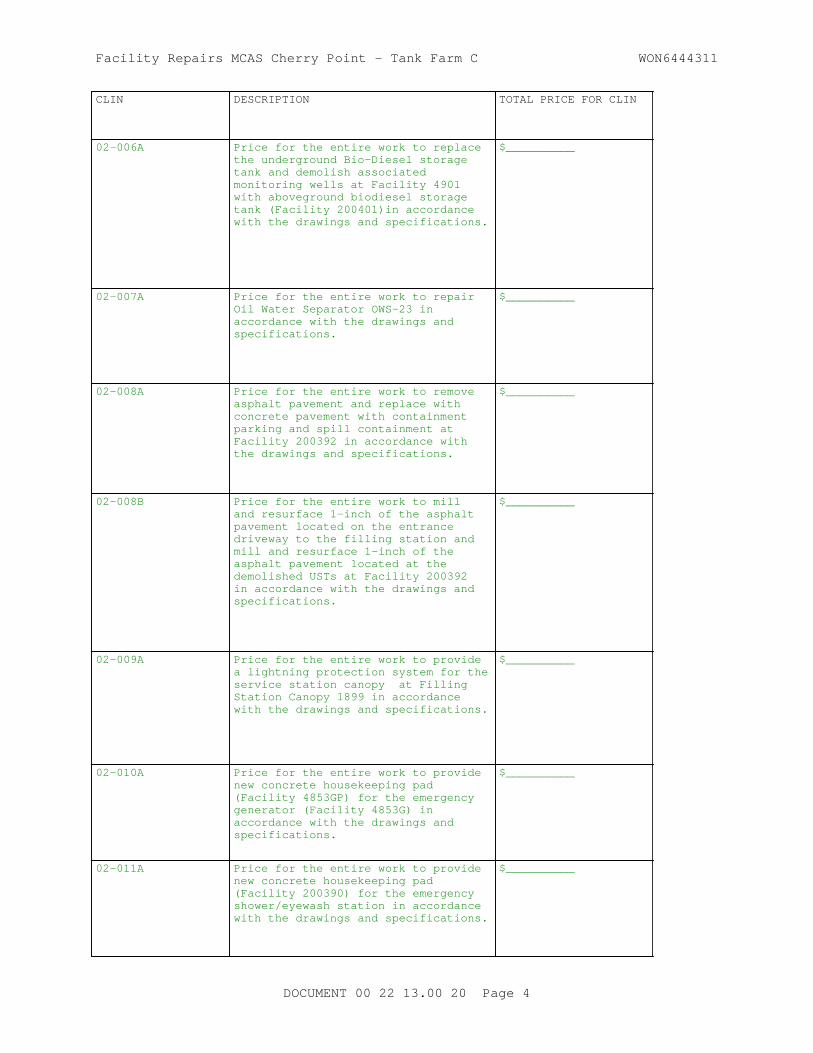
02-006A Price for the entire work to replace the underground Bio-Diesel storage tank and demolish associated monitoring wells at Facility 4901 with aboveground biodiesel storage tank (Facility 200401)in accordance with the drawings and specifications.
$__________
02-007A Price for the entire work to repair Oil Water Separator OWS-23 in accordance with the drawings and specifications.
$__________
02-008A Price for the entire work to remove asphalt pavement and replace with concrete pavement with containment parking and spill containment at Facility 200392 in accordance with the drawings and specifications.
$__________
02-008B Price for the entire work to mill and resurface 1-inch of the asphalt pavement located on the entrance driveway to the filling station and mill and resurface 1-inch of the asphalt pavement located at the demolished USTs at Facility 200392 in accordance with the drawings and specifications.
$__________
02-009A Price for the entire work to provide a lightning protection system for the service station canopy at Filling Station Canopy 1899 in accordance with the drawings and specifications.
$__________
02-010A Price for the entire work to provide new concrete housekeeping pad (Facility 4853GP) for the emergency generator (Facility 4853G) in accordance with the drawings and specifications.
$__________
02-011A Price for the entire work to provide new concrete housekeeping pad (Facility 200390) for the emergency shower/eyewash station in accordance with the drawings and specifications.
$__________
DOCUMENT 00 22 13.00 20 Page 4

Facility Repairs MCAS Cherry Point - Tank Farm C WON6444311
CLIN DESCRIPTION TOTAL PRICE FOR CLIN
02-012A Price for the entire work to provide new concrete housekeeping pad (Facility 200391) for the aboveground storage tanks in accordance with the drawings and specifications.
$__________
02-013A Price for the entire work to provide water distribution line (Facility 202547) to the emergency shower in accordance with the drawings and specifications.
$__________
02-014A Price for the entire work to provide Mogas piping (Facility 200406) between the tank and dispensing/off-load equipment in accordance with the drawings and specifications.
$__________
02-015A Price for the entire work to provide biodiesel piping (Facility 200407) between the tank and dispensing/off-load equipment in accordance with the drawings and specifications.
$__________
02-016A Price for the entire work to provide E85 piping (Facility 200408) between the tank and dispensing/off-load equipment in accordance with the drawings and specifications.
$__________
02-017A Price for the entire work to provide diesel piping (Facility 200409) between the tank and dispensing/off-load equipment in accordance with the drawings and specifications.
$__________
CLIN 02AE. UNIT PRICE - Price includes the following:
Contractor shall provide with their proposal, a per cubic yard unit price line item for the removal, stockpiling, testing and off station disposal of contaminated soil as described in Specificaiton Section 31 23 00.00 20 EXCAVATION AND FILL.
DOCUMENT 00 22 13.00 20 Page 5

Facility Repairs MCAS Cherry Point - Tank Farm C WON6444311
CLIN DESCRIPTION PRICE PER CUBIC YARD
02AE Removal, stockpiling, testing and off station disposal of contamintaed soil in accordance with Specification Section 31 23 00.00 20 EXCAVATION AND FILL.
$__________ /cy
CLIN 02AF. UNIT PRICE - Price includes the following:
Contractor shall provide with their proposal, a per gallon unit price line item for the removal, testing and off station disposal of contaminated ground water as described in Specificaiton Section 31 23 00.00 20 EXCAVATION AND FILL.
CLIN DESCRIPTION PRICE PER GALLON
02AF Removal, testing and off station disposal of contamintaed ground water in accordance with Specification Section 31 23 00.00 20 EXCAVATION AND FILL.
$__________/GAL
CLIN 02-002F . BID OPTION ITEM NO. 1 - Price Includes the following:
Price for porviding all work in connection with providing surveillance cameras at Filling Station 1899 in accordance with the drawings and specifications.
CLIN DESCRIPTION TOTAL PRICE FOR CLIN
02-002F Price for the entire work to provide surveillance cameras at Filling Station 1899 in accordance with the drawings and specifications.
$__________
PART 2 PRODUCTS
Not used.
PART 3 EXECUTION
Not used.
-- End of Document --
DOCUMENT 00 22 13.00 20 Page 6

Facility Repairs MCAS Cherry Point - Tank Farm C WON6444311
SECTION 01 11 00
SUMMARY OF WORK08/15
PART 1 GENERAL
1.1 WORK COVERED BY CONTRACT DOCUMENTS
1.1.1 Project Description
The work includes includes replacement of the (3) existing underground tanks and piping that issues fuel to the dispensers with (3) aboveground tanks, cleaning of the existing aboveground E85 fuel tank to convert to use as MOGAS storage, asphalt repairs, concrete containment repairs, miscellaneous other facility repairs, and incidental related work.
1.1.2 Location
The work is located at MACS Cherry Point, North Carolina , approximately as indicated. The exact location will be shown by the Contracting Officer.
1.2 OCCUPANCY OF PREMISES
Building(s) will be occupied during performance of work under this Contract. Occupancy notifications will be posted in a prominent location in the work area.
Before work is started, arrange with the Contracting Officer a sequence of procedure, means of access, space for storage of materials and equipment, and use of approaches, corridors, and stairways.
1.3 EXISTING WORK
In addition to "FAR 52.236-9, Protection of Existing Vegetation, Structures, Equipment, Utilities, and Improvements":
a. Remove or alter existing work in such a manner as to prevent injury or damage to any portions of the existing work which remain.
b. Repair or replace portions of existing work which have been altered during construction operations to match existing or adjoining work, as approved by the Contracting Officer. At the completion of operations, existing work must be in a condition equal to or better than that which existed before new work started.
1.4 LOCATION OF UNDERGROUND UTILITIES
It shall be the responsibility of the contractor to locate all existingunderground utilities that are within the limits of work, prior to anyexcavation activities. These include but are not limited to the followingburied utilities: water lines, sanitary and storm sewers, steamcondensate, fuel lines, gas lines, electrical ducts and direct buriedconductors, commercial telephone, Base telephone, commercial cable TV, Baseinstructional cable TV, EMCS and fire alarm. The contractor shall employthe services of a qualified Utility locating company to locate, identify,and mark all underground utilities. The entire construction limits shallbe thoroughly scanned and researched to determine existing utility
SECTION 01 11 00 Page 1

Facility Repairs MCAS Cherry Point - Tank Farm C WON6444311
locations. Any existing utilities that are indicated on the projectdrawings shall be considered for reference use by the locating company andshall be verified. All underground utilities shall be clearly marked withflags, paint or stakes prior to any digging operation except that requiredto determine exact utility location and depth. CAUTION shall be used whentrenching or excavating around or near buried utilities. The contractorshall be responsible for the timely repair and/or replacement of direct andcollateral damage on any and all underground utilities that are severed,crushed, broken, displaced or otherwise disturbed by the constructionoperation. The Government shall not incur any additional cost for suchrepair or replacement. The contractor shall notify the FEAD a minimum ofthree working days prior to utility location. Do not continue withexcavation or installation of new work without resolving elevationdiscrepancies and conflicts.
1.4.1 Notification Prior to Excavation
Notify the Contracting Officer at least 15 days prior to starting excavation work.
PART 2 PRODUCTS
Not used.
PART 3 EXECUTION
Not used. -- End of Section --
SECTION 01 11 00 Page 2

Facility Repairs MCAS Cherry Point - Tank Farm C WON6444311
SECTION 01 14 00
WORK RESTRICTIONS11/11
PART 1 GENERAL
1.1 SPECIAL SCHEDULING REQUIREMENTS
a. Have materials, equipment, and personnel required to perform the work at the site prior to the commencement of the work.
b. The MCAS Cherry Point will remain in operation during the entire construction period. The Contractor must conduct his operations so as to cause the least possible interference with normal operations of the activity.
c. Permission to interrupt any Activity roads, railroads, or utility service must be requested in writing a minimum of 15 calendar days prior to the desired date of interruption.
1.2 CONTRACTOR ACCESS AND USE OF PREMISES
Non-DoD cardholding visitors to Marine Corps Installations with a driver's license or ID issued by a state that is not compliant with the Real ID Act of 2005 will now need to provide an alternate form of acceptable identification to gain entry, or be escorted by an authorized patron of the air station.
North Carolina now issues REAL ID compliant drivers licenses, but many drivers have yet to be issued the new license. Drivers may get a North Carolina REAL ID driver's license at any NCDMV driver's license office.
The Act established minimum security standards for license issuance and production and prohibits Federal agencies from accepting driver's licenses and identification cards from states not meeting the Act's minimum standards.
In absence of a compliant state issued driver's license or ID, one of the following federally approved forms of identification must also be provided in addition to the non-compliant driver's license or ID:
1. U.S. Passport2. U.S. Passport Card3. U.S. Coast Guard Merchant Mariner Card4. Personal Identity Verification (PIV) Card5. Personal Identity Verification - Interoperable (PIV-I)6. U.S. State Department Driver's License7. Veteran's Health Identification Card (Issued by the U.S. Department ofVeterans Affairs)8. U.S. Permanent Resident Card (Form I-551)
1.2.1 Activity Regulations
Ensure that Contractor personnel employed on the Activity become familiar with and obey Activity regulations including safety, fire, traffic and security regulations. Keep within the limits of the work and avenues of
SECTION 01 14 00 Page 1
Facility Repairs MCAS Cherry Point - Tank Farm C WON6444311
ingress and egress. Wear hard hats in designated areas. Do not enter any restricted areas unless required to do so and until cleared for such entry. Mark Contractor equipment for identification.
1.2.1.1 DBIDS Identification Badges and Installation Access
Obtain access to Navy installations through participation in the Defense Biometrics Identification System (DBIDS). Requirements for Contractor employee registration, and transition for employees currently under Navy Commercial Access Control System (NCACS), are available at https://www.cnic.navy.mil/om/dbids.html. No fees are associated with obtaining a DBIDS credential.
Participation in the DBIDS is not mandatory, and Contractor personnel may apply for One-Day Passes at the Base Visitor Control Office to access an installation.
1.2.1.1.1 Registration for DBIDS
Registration for DBIDS is available at https://www.cnic.navy.mil/om/dbids.html. Procedure includes:
a. Present a letter or official award document (i.e. DD Form 1155 or SF 1442) from the Contracting Officer, that provides the purpose for access, to the base Visitor Control Center representative.
b. Present valid identification, such as a passport or Real ID Act-compliant state driver's license.
c. Provide completed SECNAV FORM 5512/1 to the base Visitor Control Center representative to obtain a background check. This form is available for download at https://www.cnic.navy.mil/om/dbids.html.
d. Upon successful completion of the background check, the Government will complete the DBIDS enrollment process, which includes Contractor employee photo, finger prints, base restriction and several other assessments.
e. Upon successful completion of the enrollment process, the Contractor employee will be issued a DBIDS credential, and will be allowed to proceed to worksite.
1.2.1.1.2 DBIDS Eligibility Requirements
Throughout the lenght of the contract, the Contractor employee must continue to meet background screen standards. Periodic background screenings are conducted to verify continued DBIDS participation and installation access privileges. DBIDS access privileges will be immediately suspended or revoked if at any time a Contractor employee becomes ineligible.
An adjudication process may be initiated when a background screen failure results in disqualification from participation in the DBIDS, and Contractor employee does not agree with the reason for disqualification. The Government is the final authority.
1.2.1.1.3 DBIDS Notification Requirements
a. Immediately report instances of lost or stolen badges to the
SECTION 01 14 00 Page 2

Facility Repairs MCAS Cherry Point - Tank Farm C WON6444311
Contracting Officer.
b. Immediately collect DBIDS credentials and notify the Contracting Officer in writing under the following circumstances:
(1) An employee has departed the company without having properly returned or surrendered their DBIDS credentials.
(2) There is a reasonable basis to conclude that an employee, or former employee, might pose a risk, compromise, or threat to the safety or security of the Installation or anyone therein.
1.2.1.1.4 One-Day Passes
Personnel applying for One-Day passes at the Base Visitor Control Office are subject to daily mandatory vehicle inspection, and will have limited access to the installation. The Government is not responsible for any cost or lost time associated with obtaining daily passes or added vehicle inspections incurred by non-participants in the DBIDS.
1.2.1.2 NCACS Identification Badges and Installation Access
Application for and use of badges will be as directed. Obtain access to the installation by participating in the Navy Commercial Access Control System (NCACS), or by obtaining passes each day from the Base Pass and Identification Office. Costs for obtaining passes through the NCACS are the responsibility of the Contractor. One-day passes, issued through the Base Pass and Identification Office, will be furnished without charge. Furnish a completed EMPLOYMENT ELIGIBILITY VERIFICATION (DHS FORM I-9) form for all personnel requesting badges. This form is available athttp://www.uscis.gov/portal/site/uscis by searching or selecting Employment Verification (Form I-9). Immediately report instances of lost or stolen badges to the Contracting Officer.
a. NCACS Program: NCACS is a voluntary program in which Contractor personnel who enroll, and are approved, are subsequently granted access to the installation for a period up to one year, or the length of the contract, whichever is less, and are not required to obtain a new pass from the Base Pass and Identification Office for each visit. The Government performs background screening and credentialing. Throughout the year the Contractor employee must continue to meet background screening standards. Periodic background screenings are conducted to verify continued NCACS participation and installation access privileges. Under the NCACS program, no commercial vehicle inspection is required, other than for Random Anti-Terrorism Measures (RAM) or in the case of an elevation of Force Protection Conditions (FPCON). Information on costs and requirements to participate and enroll in NCACS is available at http://www.rapidgate.com or by calling 1-877-727-4342. Contractors should be aware that the costs incurred to obtain NCACS credentials, or costs related to any means of access to a Navy Installation, are not reimbursable. Any time invested, or price(s) paid, for obtaining NCACS credentials will not be compensated in any way or approved as a direct cost of any contract with the Department of the Navy.
b. One-Day Passes: Participation in the NCACS is not mandatory, and if the Contractor chooses to not participate, the Contractor's personnel will have to obtain daily passes, be subject to daily mandatory vehicle inspection, and will have limited access to the installation. The
SECTION 01 14 00 Page 3

Facility Repairs MCAS Cherry Point - Tank Farm C WON6444311
Government will not be responsible for any cost or lost time associated with obtaining daily passes or added vehicle inspections incurred by non-participants in the NCACS.
1.2.1.3 No Smoking Policy
Smoking is prohibited within and outside of all buildings on installation, except in designated smoking areas. This applies to existing buildings, buildings under construction and buildings under renovation. Discarding tobacco materials other than into designated tobacco receptacles is considered littering and is subject to fines. The Contracting Officer will identify designated smoking areas.
1.2.2 Working Hours
Regular working hours must consist of an 8 1/2 hour period, between 7 a.m. and 3:30 p.m., Monday through Friday, excluding Government holidays.
1.2.3 Work Outside Regular Hours
Work outside regular working hours requires Contracting Officer approval. Make application 15 calendar days prior to such work to allow arrangements to be made by the Government for inspecting the work in progress, giving the specific dates, hours, location, type of work to be performed, contract number and project title. Based on the justification provided, the Contracting Officer may approve work outside regular hours. During periods of darkness, the different parts of the work must be lighted in a manner approved by the Contracting Officer. Make utility cutovers after normal working hours or on Saturdays, Sundays, and Government holidays unless directed otherwise.
1.2.4 Occupied Building[s]
The Contractor shall be working around existing buildings which are occupied. Do not enter the building[s] without prior approval of the Contracting Officer.
The existing buildings and their contents must be kept secure at all times. Provide temporary closures as required to maintain security as directed by the Contracting Officer.
1.2.5 Utility Cutovers and Interruptions
a. Make utility cutovers and interruptions after normal working hours or on Saturdays, Sundays, and Government holidays. Conform to procedures required paragraph WORK OUTSIDE REGULAR HOURS.
b. Ensure that new utility lines are complete, except for the connection, before interrupting existing service.
c. Interruption of , but not limited to, water, sanitary sewer, storm sewer, telephone service, electric service, air conditioning, heating, fire alarm, and compressed air are considered utility cutovers pursuant to the paragraph WORK OUTSIDE REGULAR HOURS.
SECTION 01 14 00 Page 4

Facility Repairs MCAS Cherry Point - Tank Farm C WON6444311
1.3 SECURITY REQUIREMENTS
1.3.1 Station Regulations
No employee or representative of the contractor will be admitted to the work site without an Identification Badge or is specifically authorized admittance to the work site by the FEAD, Facilities Engineering & Acquisition Division.
IMPORTANT NOTE: FEAD personnel (Construction Managers, Engineers/Architects, Engineering Technicians, Contract Specialists, or Contract Surveillance Representatives) will not receive, process, re-transmit or otherwise handle IN ANY WAY Personally Identifiable Information (PII) related to the badging process. Do NOT forward any of this information to the FEAD.
1.3.2 Contractor Access to MCAS Cherry Point and Outlying Areas
1. Documentation requirements for granting access to MCAS Cherry Point for commercial and contract employers and employees. This document is an aid in meeting ASO 5560.6A requirements and is not a substitute for the order.
2. The Pass & Identification Office at Building 251 will issue credentials to authorized contractors. Sub-Contractors and suppliers must coordinate through the Prime-Contractor:
3. Criminal Activity. In accordance with ASO 5560.6A, the below list of criminal activities within an applicant's record are considered not in the best interest of the Marine Corps and will be grounds for automatic denial of access aboard the Installation:
a. Conviction of any felony offense.
b. Conviction of any misdemeanor offense, which was the result of a plea bargain of a felony offense.
c. Conviction of any offense involving a weapon.
d. Conviction of any drug offense involving manufacturing or trafficking.
e. More than one misdemeanor conviction of drug related offenses over the applicant's lifetime or one misdemeanor drug related offense within the last five years.
f. Conviction of any assault charge.
g. Conviction of any offense involving theft or larceny.
h. Conviction of any offense of domestic violence.
i. Conviction of any offense related to the abuse/neglect of a child.
j. Conviction of any sexual in nature related offense or registration as a sex offender.
k. Commission of any grievous criminal offense/misconduct while aboard any Federal installation, including blatant disregard for
SECTION 01 14 00 Page 5
Facility Repairs MCAS Cherry Point - Tank Farm C WON6444311
rules and regulations of the Installation, but excluding minor traffic offenses.
l. Other than Honorable, Bad Conduct, and Dishonorable discharges from the U.S. Military.
m. Those identified as undocumented citizens.
n. Those on the National Terrorist Watch List.
o. Any individual who attempts to hide or purposely fails to disclose all past criminal history during the vetting process.
p. Any individual that the Provost Marshal's Office determines to present a risk to the security and safety of the Installation and whose access is deemed not in the best interest of the Marine Corps.
q. Any individual who has been debarred from the Installation by the Installation Commander or is currently listed as debarred from any other Federal installation.
r. Any individual with an outstanding warrant for their arrest or apprehension.
s. Any individual with a pending criminal court case that, if convicted, would result in access denial in accordance with the criteria listed above.
1.3.3 FLIGHTLINE SECURITY REQUIREMENTS
Work involved under this contract is in the Flightline Security Area. No employee or representative of the Contractor will be admitted to the work site unless they (1) are specifically authorized admittance by the FEAD, and (2) have a security badge. The Contractor shall obtain clearance and flightline security badges for all personnel required to be on the project site prior to performing any work. The Contractor shall submit a written request for security badges to the FEAD and to Pass & ID. Each employee will be required to go to PASS & ID at Building 251 to obtain his security badge with flightline access. A limited number of Contractor vehicles will be allowed access to the site of work subject to meeting regular Station access requirements. No personal vehicles will be allowed behind the security fence. Parking of vehicles shall be restricted to the immediate project site as determined by the FEAD. The security badges issued under this contract are valid for this specific project and are not transferable to another project.
1.3.4 Staging Area
As indicated on the plans, the Contractor staging area will be coordinated by the Contracting Officer. Amount of material on site shall be kept to a minimum and shall only be material that is pertinent to the work currently being performed. All stockpiling of equipment and materials shall be closely coordinated with the Government and shall not disrupt activities at the site.
SECTION 01 14 00 Page 6

Facility Repairs MCAS Cherry Point - Tank Farm C WON6444311
PART 2 PRODUCTS
Not Used
PART 3 EXECUTION
Not Used
-- End of Section --
SECTION 01 14 00 Page 7

Facility Repairs MCAS Cherry Point - Tank Farm C WON6444311
SECTION 01 20 00.00 20
PRICE AND PAYMENT PROCEDURES11/11
PART 1 GENERAL
1.1 REFERENCES
The publications listed below form a part of this specification to the extent referenced. The publications are referred to within the text by the basic designation only.
U.S. ARMY CORPS OF ENGINEERS (USACE)
EP-1110-1-8 (2009) Construction Equipment Ownership and Operating Expense Schedule
1.2 SUBMITTALS
Submit the following in accordance with Section 01 33 00 SUBMITTAL PROCEDURES:
SD-01 Preconstruction Submittals
Schedule of Prices ; G
1.3 SCHEDULE OF PRICES
1.3.1 Data Required
Within 15 calendar days of notice of award, prepare and deliver to the Contracting Officer a Schedule of Prices (construction contract) as directed by the Contracting Officer. Provide a detailed breakdown of the contract price, giving quantities for each of the various kinds of work, unit prices, and extended prices. Costs shall be summarized and totals provided for each construction category.
1.3.2 Schedule Instructions
Payments will not be made until the Schedule of Prices has been submitted to and accepted by the Contracting Officer. Identify the cost for site work, and include incidental work to the 5 ft line. Identify costs for the building(s), and include work out to the 5 ft line. Work out to the 5 ft line shall include construction encompassed within a theoretical line 5 ft from the face of exterior walls and shall include attendant construction, such as pad mounted HVAC cooling equipment, cooling towers, and transformers placed beyond the 5 ft line.
1.4 CONTRACT MODIFICATIONS
In conjunction with the Contract Clause "DFARS 252.236-7000, Modification Proposals-Price Breakdown," and where actual ownership and operating costs of construction equipment cannot be determined from Contractor accounting records, equipment use rates shall be based upon the applicable provisions of the EP-1110-1-8 .
SECTION 01 20 00.00 20 Page 1

Facility Repairs MCAS Cherry Point - Tank Farm C WON6444311
1.5 CONTRACTOR'S INVOICE AND CONTRACT PERFORMANCE STATEMENT
1.5.1 Content of Invoice
Requests for payment will be processed in accordance with the Contract Clause FAR 52.232-27, Prompt Payment Construction Contracts and FAR 52.232-5, Payments Under Fixed-Price Construction Contracts. The requests for payment shall include the documents listed below.
a. The Contractor's invoice, on NAVFAC Form 7300/30 furnished by the Government, showing in summary form, the basis for arriving at the amount of the invoice. Form 7300/30 shall include certification by Contractor and Quality Control (QC) Manager.
b. The Estimate for Voucher/ Contract Performance Statement on NAVFAC Form 4330/54 furnished by the Government, showing in detail: the estimated cost, percentage of completion, and value of completed performance. Use NAVFAC Form 43300/54 on NAVFAC contracts when a Monthly Estimate for Voucher is required.
c. Updated Project Schedule and reports required by the contract.
d. Contractor Safety Self Evaluation Checklist.
e. Other supporting documents as requested.
f. Updated copy of submittal register.
g. Invoices not completed in accordance with contract requirements will be returned to the Contractor for correction of the deficiencies.
h. Contractor's Monthly Estimate for Voucher and Conractors Certification (NAVFAC Form 4330/54) with Subcontractor and supplier payment certification.
i. Materials on Site.1.5.2 Submission of Invoices
If DFARS Clause 5252.232-7006 is included in the contract, provide the documents listed in paragraph CONTENT OF INVOICE in their entirety as attachments in Wide Area Work Flow (WAWF) for each invoice submitted. The maximum size of each WAWF attachment is two megabytes, but there are no limits on the number of attachments. If a document cannot be attached in WAWF due to system or size restriction, provide it as instructed by the Contracting Officer.
Monthly invoices and supporting forms for work performed through the anniversary award date of the contract shall be submitted to the Contracting Officer within 5 calendar days of the date of invoice. For example, contract award date is the 7th of the month, the date of each monthly invoice shall be the 7th and the invoice shall be submitted by the 12th of the month.
1.5.3 Final Invoice
a. A final invoice shall be accompanied by the certification required by DFARS 252.247.7023 TRANSPORTATION OF SUPPLIES BY SEA, and the Contractor's Final Release. If the Contractor is incorporated, the Final Release shall contain the corporate seal. An officer of the
SECTION 01 20 00.00 20 Page 2

Facility Repairs MCAS Cherry Point - Tank Farm C WON6444311
corporation shall sign and the corporate secretary shall certify the Final Release.
b. For final invoices being submitted via WAWF, the original Contractor's Final Release Form and required certification of Transportation of Supplies by Sea must be provided directly to the respective Contracting Officer prior to submission of the final invoice. Once receipt of the original Final Release Form and required certification of Transportation of Supplies by Sea has been confirmed by the Contracting Officer, the Contractor shall then submit final invoice and attach a copy of the Final Release Form and required certification of Transportation of Supplies by Sea in WAWF.
c. Final invoices not accompanied by the Contractor's Final Release and required certification of Transportation of Supplies by Sea will be considered incomplete and will be returned to the Contractor.
1.6 PAYMENTS TO THE CONTRACTOR
Payments will be made on submission of itemized requests by the Contractor which comply with the requirements of this section, and will be subject to reduction for overpayments or increase for underpayments made on previous payments to the Contractor.
1.6.1 Obligation of Government Payments
The obligation of the Government to make payments required under the provisions of this contract will, at the discretion of the Contracting Officer, be subject to reductions and suspensions permitted under the FAR and agency regulations including the following in accordance with FAR 32.503-6:
a. Reasonable deductions due to defects in material or workmanship;
b. Claims which the Government may have against the Contractor under or in connection with this contract;
c. Unless otherwise adjusted, repayment to the Government upon demand for overpayments made to the Contractor; and
d. Failure to provide up to date record drawings not current as stated in Contract Clause "FAC 5252.236-9310, Record Drawings."
1.6.2 Payment for Onsite and Offsite Materials
Progress payments may be made to the contractor for materials delivered on the site, for materials stored off construction sites, or materials that are in transit to the construction sites under the following conditions:
a. FAR 52.232-5(b) Payments Under Fixed Price Construction Contracts.
b. Materials delivered on the site but not installed, including completed preparatory work, and off-site materials to be considered for progress payment shall be major high cost, long lead, special order, or specialty items, not susceptible to deterioration or physical damage in storage or in transit to the construction site. Examples of materials acceptable for payment consideration include, but are not limited to, structural steel, non-magnetic steel, non-magnetic aggregate, equipment, machinery, large pipe and fittings,precast/prestressed
SECTION 01 20 00.00 20 Page 3

Facility Repairs MCAS Cherry Point - Tank Farm C WON6444311
concrete products, plastic lumber (e.g., fender piles/curbs), and high-voltage electrical cable. Materials not acceptable for payment include consumable materials such as nails, fasteners, conduits, gypsum board, glass, insulation, and wall coverings.
c. Materials to be considered for progress payment prior to installation shall be specifically and separately identified in the Contractor's estimates of work submitted for the Contracting Officer's approval in accordance with Schedule of Prices requirement of this contract. Requests for progress payment consideration for such items shall be supported by documents establishing their value and that the title requirements of the clause at FAR 52.232-5 have been met.
d. Materials are adequately insured and protected from theft and exposure.
e. Provide a written consent from the surety company with each payment request for offsite materials.
f. Materials to be considered for progress payments prior to installation shall be stored either in Hawaii, Guam, Puerto Rico, or the Continental United States. Other locations are subject to written approval by the Contracting Officer.
PART 2 PRODUCTS
Not Used
PART 3 EXECUTION
Not Used
-- End of Section --
SECTION 01 20 00.00 20 Page 4

Facility Repairs MCAS Cherry Point - Tank Farm C WON6444311
SECTION 01 30 00
ADMINISTRATIVE REQUIREMENTS08/15
PART 1 GENERAL
1.1 REFERENCES
The publications listed below form a part of this specification to the extent referenced. The publications are referred to within the text by the basic designation only.
U.S. ARMY CORPS OF ENGINEERS (USACE)
EM 385-1-1 (2014) Safety and Health Requirements Manual
1.2 SUBMITTALS
Government approval is required for the following in accordance with Section 01 33 00 SUBMITTAL PROCEDURES:
SD-01 Preconstruction Submittals
List of Contact Personnel
1.2.1 Contact Personnel
Furnish a list of contact personnel of the Contractor and subcontractors including addresses and telephone numbers for use in the event of an emergency. As changes occur and additional information becomes available, correct and change the information contained in previous lists.
1.3 MINIMUM INSURANCE REQUIREMENTS
Provide the minimum insurance coverage required by FAR 28.307-2 LIABILITY, during the entire period of performance under this contract. Provide other insurance coverage as required by North Carolina State law.
1.4 FIRST TIER CONTRACTOR REQUIREMENTS FOR ASBESTOS CONTAINING MATERIALS
Accomplish all contract requirements of Section 02 82 16.00 20 ENGINEERING CONTROL OF ASBESTOS CONTAINING MATERIALS, assigned to the Private Qualified Person, directly with a first tier subcontractor.
1.5 SUPERVISION
1.5.1 Minimum Communication Requirements
Have at least one qualified superintendent, or competent alternate, capable of reading, writing, and conversing fluently in the English language, on the job-site at all times during the performance of contract work. In addition, if a Quality Control (QC) representative is required on the contract, then that individual must also have fluent English communication skills.
SECTION 01 30 00 Page 1

Facility Repairs MCAS Cherry Point - Tank Farm C WON6444311
1.5.2 Superintendent Qualifications
The project superintendent must have a minimum of 10 years experience in construction with at least 5 of those years as a superintendent on projects similar in size and complexity. The individual must be familiar with the requirements of EM 385-1-1 and have experience in the areas of hazard identification and safety compliance. The individual must be capable of interpreting a critical path schedule and construction drawings. The qualification requirements for the alternate superintendent are the same as for the project superintendent. The Contracting Officer may request proof of the superintendent's qualifications at any point in the project if the performance of the superintendent is in question.
For routine projects where the superintendent is permitted to also serve as the Quality Control (QC) Manager as established in Section [ 01 45 00.00 20 QUALITY CONTROL, the superintendent must have qualifications in accordance with that section.
1.5.2.1 Duties
The project superintendent is primarily responsible for managing and coordinating day-to-day production and schedule adherence on the project. The superintendent is required to attend NAVFAC Red Zone meetings, partnering meetings, and quality control meetings. The superintendent or qualified alternative must be on-site at all times during the performance of this contract until the work is completed and accepted.
1.5.3 Non-Compliance Actions
The Project Superintendent is subject to removal by the Contracting Officer for non-compliance with requirements specified in the contract and for failure to manage the project to insure timely completion. Furthermore, the Contracting Officer may issue an order stopping all or part of the work until satisfactory corrective action has been taken. No part of the time lost due to such stop orders is acceptable as the subject of claim for extension of time for excess costs or damages by the Contractor.
1.6 PRECONSTRUCTION MEETING
After award of the contract but prior to commencement of any work at the site, meet with the Contracting Officer to discuss and develop a mutual understanding relative to the administration of the value engineering and safety program, preparation of the schedule of prices or earned value report, shop drawings, and other submittals, scheduling programming, prosecution of the work, and clear expectations of the "Interim DD Form 1354" Submittal. Major subcontractors who will engage in the work must also attend.
1.7 PARTNERING
To most effectively accomplish this contract, the Government requires the formation of a cohesive partnership within the Project Team whose members are from the Government, the Contractor and their Subcontractors. Key personnel from the Supported Command, the End User (who will occupy the facility), the Government Design and Construction team and Subject Matter Experts, the Installation, the Contractor and Subcontractors, and the Designer of Record will be invited to participate in the Partnering process. The Partnership will draw on the strength of each organization in an effort to achieve a project that is without any safety mishaps, conforms
SECTION 01 30 00 Page 2

Facility Repairs MCAS Cherry Point - Tank Farm C WON6444311
to the Contract, and stays within budget and on schedule.
The Contracting Officer will provide Information on the Partnering Process and a list of key and optional personnel who should attend the Partnering meeting.
1.8 ELECTRONIC MAIL (E-MAIL) ADDRESS
Establish and maintain electronic mail (e-mail) capability along with the capability to open various electronic attachments as text files, pdf files, and other similar formats. Within 10 days after contract award, provide the Contracting Officer a single (only one) e-mail address for electronic communications from the Contracting Officer related to this contract including, but not limited to contract documents, invoice information, request for proposals, and other correspondence. The Contracting Officer may also use email to notify the Contractor of base access conditions when emergency conditions warrant, such as hurricanes or terrorist threats. Multiple email addresses are not allowed.
It is the Contractor's responsibility to make timely distribution of all Contracting Officer initiated e-mail with its own organization including field office(s). Promptly notify the Contracting Officer, in writing, of any changes to this email address.
PART 2 PRODUCTS
Not Used
PART 3 EXECUTION
Not Used
-- End of Section --
SECTION 01 30 00 Page 3


Facility Repairs MCAS Cherry Point - Tank Farm C WON6444311
SECTION 01 33 00
SUBMITTAL PROCEDURES05/11
PART 1 GENERAL
1.1 DEFINITIONS
1.1.1 Submittal Descriptions (SD)
Submittals requirements are specified in the technical sections. Submittals are identified by Submittal Description (SD) numbers and titles as follows:
SD-01 Preconstruction Submittals
Submittals which are required prior to or commencing work on site.
Certificates of insurance
Surety bonds
List of proposed Subcontractors
List of proposed products
Construction progress schedule
Network Analysis Schedule (NAS)
Submittal register
Schedule of prices
Health and safety plan
Work plan
Quality Control(QC) plan
Environmental protection plan
SD-02 Shop Drawings
Drawings, diagrams and schedules specifically prepared to illustrate some portion of the work.
Diagrams and instructions from a manufacturer or fabricator for use in producing the product and as aids to the Contractor for integrating the product or system into the project.
Drawings prepared by or for the Contractor to show how multiple systems and interdisciplinary work will be coordinated.
SD-03 Product Data
Catalog cuts, illustrations, schedules, diagrams, performance charts,
SECTION 01 33 00 Page 1

Facility Repairs MCAS Cherry Point - Tank Farm C WON6444311
instructions and brochures illustrating size, physical appearance and other characteristics of materials, systems or equipment for some portion of the work.
Samples of warranty language when the contract requires extended product warranties.
SD-05 Design Data
Design calculations, mix designs, analyses or other data pertaining to a part of work.
SD-06 Test Reports
Report signed by authorized official of testing laboratory that a material, product or system identical to the material, product or system to be provided has been tested in accord with specified requirements. Unless specified in another section, testing must have been within three years of date of contract award for the project.
Report which includes findings of a test required to be performed by the Contractor on an actual portion of the work or prototype prepared for the project before shipment to job site.
Report which includes finding of a test made at the job site or on sample taken from the job site, on portion of work during or after installation.
Investigation reports.
Daily logs and checklists.
Final acceptance test and operational test procedure.
SD-07 Certificates
Statements printed on the manufacturer's letterhead and signed by responsible officials of manufacturer of product, system or material attesting that the product, system, or material meets specification requirements. Must be dated after award of project contract and clearly name the project.
Document required of Contractor, or of a manufacturer, supplier, installer or Subcontractor through Contractor. The document purpose is to further promote the orderly progression of a portion of the work by documenting procedures, acceptability of methods, or personnel qualifications.
Confined space entry permits.
Text of posted operating instructions.
SD-08 Manufacturer's Instructions
Preprinted material describing installation of a product, system or material, including special notices and (MSDS)concerning impedances, hazards and safety precautions.
SECTION 01 33 00 Page 2

Facility Repairs MCAS Cherry Point - Tank Farm C WON6444311
SD-09 Manufacturer's Field Reports
Documentation of the testing and verification actions taken by manufacturer's representative at the job site, in the vicinity of the job site, or on a sample taken from the job site, on a portion of the work, during or after installation, to confirm compliance with manufacturer's standards or instructions. The documentation must be signed by an authorized official of a testing laboratory or agency and state the test results; and indicate whether the material, product, or system has passed or failed the test.
Factory test reports.
SD-10 Operation and Maintenance Data
Data that is furnished by the manufacturer, or the system provider, to the equipment operating and maintenance personnel, including manufacturer's help and product line documentation necessary to maintain and install equipment. This data is needed by operating and maintenance personnel for the safe and efficient operation, maintenance and repair of the item.
This data is intended to be incorporated in an operations and maintenance manual or control system.
SD-11 Closeout Submittals
Documentation to record compliance with technical or administrative requirements or to establish an administrative mechanism.
Special requirements necessary to properly close out a construction contract. For example, Record Drawings and as-built drawings. Also, submittal requirements necessary to properly close out a major phase of construction on a multi-phase contract.
1.1.2 Approving Authority
Office or designated person authorized to approve submittal.
1.1.3 Work
As used in this section, on- and off-site construction required by contract documents, including labor necessary to produce submittals , except those SD-01 Pre-Construction Submittals noted above , construction, materials, products, equipment, and systems incorporated or to be incorporated in such construction.
1.2 SUBMITTALS
Government approval is required for submittals with a "G" designation; submittals not having a "G" designation are for Contractor QC review and certification prior to being submitted to the Government for apporval . Submit the following in accordance with this section.
SD-01 Preconstruction Submittals
Submittal Register ; G
SECTION 01 33 00 Page 3

Facility Repairs MCAS Cherry Point - Tank Farm C WON6444311
1.3 SUBMITTAL CLASSIFICATION
Submittals are classified as follows:
1.3.1 Government Approved (G)
Government approval is required for extensions of design, critical materials, deviations, equipment whose compatibility with the entire system must be checked, and other items as designated by the Contracting Officer. Within the terms of the Contract Clause SPECIFICATIONS AND DRAWINGS FOR CONSTRUCTION, they are considered to be "shop drawings."
1.4 FORWARDING SUBMITTALS REQUIRING GOVERNMENT APPROVAL
1.4.1 Submittals Required from the Contractor
As soon as practicable after award of contract, and before procurement of fabrication, forward to the Architect-Engineer: Austin Brockenbrough & Associates, LLP, 1011 Boulder Springs Drive, Suite 200, Richmond, VA 23225, submittals required in the technical sections of this specification, including shop drawings, product data and samples. Forward one copy of the transmittal form for all submittals to the Contracting Officer .
The Architect-Engineer for this project will review and approve for the Contracting Officer those submittals reserved for Contracting Officer approval to verify submittals comply with the contract requirements.
1.4.1.1 O&M Data
The Architect-Engineer for this project will review and approve for the Contracting Officer O&M Data to verify the submittals comply with the contract requirements; submit data specified for a given item within 30 calendar days after the item is delivered to the contract site.
In the event the Contractor fails to deliver O&M Data within the time limits specified, the Contracting Officer may withhold from progress payments 50 percent of the price of the item with which such O&M Data are applicable.
1.5 PREPARATION
1.5.1 Transmittal Form
Transmit each submittal, except sample installations and sample panels to office of approving authority. Transmit submittals with transmittal form prescribed by Contracting Officer and standard for project. On the transmittal form identify Contractor, indicate date of submittal, and include information prescribed by transmittal form and required in paragraph IDENTIFYING SUBMITTALS. Process transmittal forms to record actions regarding installations.
1.5.2 Identifying Submittals
When submittals are provided by a Subcontractor, the Prime Contractor is to prepare, review and stamp with Contractor's approval all specified submittals prior to submitting for Government approval.
Identify submittals, except sample installations and sample panels, with
SECTION 01 33 00 Page 4

Facility Repairs MCAS Cherry Point - Tank Farm C WON6444311
the following information permanently adhered to or noted on each separate component of each submittal and noted on transmittal form. Mark each copy of each submittal identically, with the following:
a. Project title and location.
b. Construction contract number.
c. Date of the drawings and revisions.
d. Name, address, and telephone number of subcontractor, supplier, manufacturer and any other subcontractor associated with the submittal.
e. Section number of the specification section by which submittal is required.
f. Submittal description (SD) number of each component of submittal.
g. When a resubmission, add alphabetic suffix on submittal description, for example, submittal 18 would become 18A, to indicate resubmission.
h. Product identification and location in project.
1.5.3 Format for SD-02 Shop Drawings
Shop drawings are not to be less than 8 1/2 by 11 inches nor more than 30 by 42 inches , except for full size patterns or templates. Prepare drawings to accurate size, with scale indicated, unless other form is required. Drawings are to be suitable for reproduction and be of a quality to produce clear, distinct lines and letters with dark lines on a white background.
Present 8 1/2 by 11 inches sized shop drawings as part of the bound volume for submittals required by section. Present larger drawings in sets.
Include on each drawing the drawing title, number, date, and revision numbers and dates, in addition to information required in paragraph IDENTIFYING SUBMITTALS.
Number drawings in a logical sequence. Contractors may use their own number system. Each drawing is to bear the number of the submittal in a uniform location adjacent to the title block. Place the Government contract number in the margin, immediately below the title block, for each drawing.
Reserve a blank space, no smaller than four inches on the right hand side of each sheet for the Government disposition stamp.
Dimension drawings, except diagrams and schematic drawings; prepare drawings demonstrating interface with other trades to scale. Use the same unit of measure for shop drawings as indicated on the contract drawings. Identify materials and products for work shown.
Include the nameplate data, size and capacity on drawings. Also include applicable federal, military, industry and technical society publication references.
Submit drawings in PDF format.
SECTION 01 33 00 Page 5

Facility Repairs MCAS Cherry Point - Tank Farm C WON6444311
1.5.4 Format of SD-03 Product Data and SD-08 Manufacturer's Instructions
Present product data submittals for each section as a complete, bound volume . Include table of contents, listing page and catalog item numbers for product data.
Indicate, by prominent notation, each product which is being submitted; indicate specification section number and paragraph number to which it pertains.
Supplement product data with material prepared for project to satisfy submittal requirements for which product data does not exist. Identify this material as developed specifically for project, with information and format as required for submission of SD-07 Certificates.
Include the manufacturer's name, trade name, place of manufacture, and catalog model or number on product data. Also include applicable federal, military, industry and technical society publication references. Should manufacturer's data require supplemental information for clarification, submit as specified for SD-07 Certificates.
Where equipment or materials are specified to conform to industry and technical society reference standards of the organizations such as American National Standards Institute (ANSI), ASTM International (ASTM), National Electrical Manufacturer's Association (NEMA), Underwriters Laboratories (UL), and Association of Edison Illuminating Companies (AEIC), submit proof of such compliance. The label or listing by the specified organization will be acceptable evidence of compliance. In lieu of the label or listing, submit a certificate from an independent testing organization, competent to perform testing, and approved by the Contracting Officer. State on the certificate that the item has been tested in accordance with the specified organization's test methods and that the item complies with the specified organization's reference standard.
Collect required data submittals for each specific material, product, unit of work, or system into a single submittal and marked for choices, options, and portions applicable to the submittal. Mark each copy of the product data identically. Partial submittals will [not] be accepted for expedition of construction effort.
Submit manufacturer's instructions prior to installation.
1.5.5 Format of SD-04 Samples
Furnish samples in sizes below, unless otherwise specified or unless the manufacturer has prepackaged samples of approximately same size as specified:
a. Sample of Equipment or Device: Full size.
b. Sample of Materials Less Than 2 by 3 inches : Built up to 8 1/2 by 11 inches .
c. Sample of Materials Exceeding 8 1/2 by 11 inches : Cut down to 8 1/2 by 11 inches and adequate to indicate color, texture, and material variations.
d. Sample of Linear Devices or Materials: 10 inch length or length to be supplied, if less than 10 inches . Examples of linear devices or
SECTION 01 33 00 Page 6

Facility Repairs MCAS Cherry Point - Tank Farm C WON6444311
materials are conduit and handrails.
e. Sample of Non-Solid Materials: Pint . Examples of non-solid materials are sand and paint.
f. Color Selection Samples: 2 by 4 inches . Where samples are specified for selection of color, finish, pattern, or texture, submit the full set of available choices for the material or product specified. Sizes and quantities of samples are to represent their respective standard unit.
g. Sample Panel: 4 by 4 feet .
h. Sample Installation: 100 square feet .
Samples Showing Range of Variation: Where variations in color, finish, pattern, or texture are unavoidable due to nature of the materials, submit sets of samples of not less than three units showing extremes and middle of range. Mark each unit to describe its relation to the range of the variation.
Reusable Samples: Incorporate returned samples into work only if so specified or indicated. Incorporated samples are to be in undamaged condition at time of use.
Recording of Sample Installation: Note and preserve the notation of area constituting sample installation but remove notation at final clean up of project.
When color, texture or pattern is specified by naming a particular manufacturer and style, include one sample of that manufacturer and style, for comparison.
1.5.6 Format of SD-05 Design Data and SD-07 Certificates
Provide design data and certificates on 8 1/2 by 11 inches paper. Provide a bound volume for submittals containing numerous pages.
1.5.7 Format of SD-06 Test Reports and SD-09 Manufacturer's Field Reports
Provide reports on 8 1/2 by 11 inches paper in a complete bound volume.
Indicate by prominent notation, each report in the submittal. Indicate specification number and paragraph number to which it pertains.
1.5.8 Format of SD-10 Operation and Maintenance Data (O&M)
Comply with the requirements specified in Section 01 78 23 OPERATION AND MAINTENANCE DATA for O&M Data format.
1.5.9 Format of SD-01 Preconstruction Submittals and SD-11 Closeout Submittals
When submittal includes a document which is to be used in project or become part of project record, other than as a submittal, do not apply Contractor's approval stamp to document, but to a separate sheet accompanying document.
SECTION 01 33 00 Page 7

Facility Repairs MCAS Cherry Point - Tank Farm C WON6444311
1.5.10 Source Drawings for Shop Drawings
The entire set of Source Drawing files (DWG) will not be provided to the Contractor. Only those requested by the Contractor to prepare shop drawings may be provided. Request the specific Drawing Number only for the preparation of Shop Drawings. These drawings may only be provided after award.
1.5.10.1 Terms and Conditions
Data contained on these electronic files must not be used for any purpose other than as a convenience in the preparation of construction data for the referenced project. Any other use or reuse shall be at the sole risk of the Contractor and without liability or legal exposure to the Government. The Contractor must make no claim and waives to the fullest extent permitted by law, any claim or cause of action of any nature against the Government, its agents or sub consultants that may arise out of or in connection with the use of these electronic files. The Contractor must, to the fullest extent permitted by law, indemnify and hold the Government harmless against all damages, liabilities or costs, including reasonable attorney's fees and defense costs, arising out of or resulting from the use of these electronic files.
These electronic Source Drawing files are not construction documents. Differences may exist between the Source Drawing files and the corresponding construction documents. The Government makes no representation regarding the accuracy or completeness of the electronic Source Drawing files, nor does it make representation to the compatibility of these files with the Contractor hardware or software. In the event that a conflict arises between the signed and sealed construction documents prepared by the Government and the furnished Source Drawing files, the signed and sealed construction documents govern. The Contractor is responsible for determining if any conflict exists. Use of these Source Drawing files does not relieve the Contractor of duty to fully comply with the contract documents, including and without limitation, the need to check, confirm and coordinate the work of all contractors for the project. If the Contractor uses, duplicates or modifies these electronic Source Drawing files for use in producing construction data related to this contract, remove all previous indicia of ownership (seals, logos, signatures, initials and dates).
1.6 QUANTITY OF SUBMITTALS
1.6.1 Number of Copies of SD-02 Shop Drawings
Submit six copies of submittals of shop drawings requiring review and approval by Contracting Officer.
1.6.2 Number of Copies of SD-03 Product Data and SD-08 Manufacturer's Instructions
Submit in compliance with quantity requirements specified for shop drawings.
1.6.3 Number of Samples SD-04 Samples
a. Submit two samples, or two sets of samples showing range of variation, of each required item. One approved sample or set of samples will be retained by approving authority and one will be returned to Contractor.
SECTION 01 33 00 Page 8

Facility Repairs MCAS Cherry Point - Tank Farm C WON6444311
b. Submit one sample panel or provide one sample installation where directed. Include components listed in technical section or as directed.
c. Submit one sample installation, where directed.
d. Submit one sample of non-solid materials.
1.6.4 Number of Copies SD-05 Design Data and SD-07 Certificates
Submit in compliance with quantity requirements specified for shop drawings.
1.6.5 Number of Copies SD-06 Test Reports and SD-09 Manufacturer's Field Reports
Submit in compliance with quantity and quality requirements specified for shop drawings other than field test results that will be submitted with QC reports.
1.6.6 Number of Copies of SD-10 Operation and Maintenance Data
Submit three copies of O&M Data to the Contracting Officer for review and approval.
1.6.7 Number of Copies of SD-01 Preconstruction Submittals and SD-11 Closeout Submittals
Unless otherwise specified, submit three sets of administrative submittals.
1.7 INFORMATION ONLY SUBMITTALS
Normally submittals for information only will not be returned. Approval of the Contracting Officer is not required on information only submittals. The Government reserves the right to require the Contractor to resubmit any item found not to comply with the contract. This does not relieve the Contractor from the obligation to furnish material conforming to the plans and specifications; will not prevent the Contracting Officer from requiring removal and replacement of nonconforming material incorporated in the work; and does not relieve the Contractor of the requirement to furnish samples for testing by the Government laboratory or for check testing by the Government in those instances where the technical specifications so prescribe.
1.8 SUBMITTAL REGISTER
Prepare and maintain submittal register, as the work progresses. Do not change data which is output in columns (c), (d), (e), and (f) as delivered by Government; retain data which is output in columns (a), (g), (h), and (i) as approved. A submittal register showing items of equipment and materials for which submittals are required by the specifications is provided as an attachment. This list may not be all inclusive and additional submittals may be required. The Government will provide the initial submittal register with the following fields completed, to the extent that will be required by the Government during subsequent usage.
Column (c): Lists specification section in which submittal is required.
Column (d): Lists each submittal description (SD No. and type,
SECTION 01 33 00 Page 9

Facility Repairs MCAS Cherry Point - Tank Farm C WON6444311
e.g. SD-02 Shop Drawings) required in each specification section.
Column (e): Lists one principal paragraph in specification section where a material or product is specified. This listing is only to facilitate locating submitted requirements. Do not consider entries in column (e) as limiting project requirements.
Column (f): Indicate approving authority for each submittal.
Thereafter, the Contractor is to track all submittals by maintaining a complete list, including completion of all data columns, including dates on which submittals are received and returned by the Government.
1.8.1 Use of Submittal Register
Submit submittal register. Submit with QC plan and project schedule. Verify that all submittals required for project are listed and add missing submittals. Coordinate and complete the following fields on the register submitted with the QC plan and the project schedule:
Column (a) Activity Number: Activity number from the project schedule.
Column (g) Contractor Submit Date: Scheduled date for approving authority to receive submittals.
Column (h) Contractor Approval Date: Date Contractor needs approval of submittal.
Column (i) Contractor Material: Date that Contractor needs material delivered to Contractor control.
1.8.2 Contractor Use of Submittal Register
Update the following fields in the Government-furnished submittal register program or equivalent fields in program utilized by Contractor with each submittal throughout contract.
Column (b) Transmittal Number: Contractor assigned list of consecutive numbers.
Column (j) Action Code (k): Date of action used to record Contractor's review when forwarding submittals to QC.
Column (l) List date of submittal transmission.
Column (q) List date approval received.
1.8.3 Approving Authority Use of Submittal Register
Update the following fields[ in the Government-furnished submittal register program or equivalent fields in program utilized by Contractor].
Column (b) Transmittal Number: Contractor assigned list of consecutive numbers.
Column (l) List date of submittal receipt.
Column (m) through (p) List Date related to review actions.
SECTION 01 33 00 Page 10
Facility Repairs MCAS Cherry Point - Tank Farm C WON6444311
Column (q) List date returned to Contractor.
1.8.4 Copies Delivered to the Government
Deliver one copy of submittal register updated by Contractor to Government with each invoice request.
1.9 VARIATIONS
Variations from contract requirements require both Designer of Record (DOR) and Government approval pursuant to contract Clause FAR 52.236-21 and will be considered where advantageous to Government.
1.9.1 Considering Variations
Discussion with Contracting Officer prior to submission, after consulting with the DOR, will help ensure functional and quality requirements are met and minimize rejections and re-submittals. When contemplating a variation which results in lower cost, consider submission of the variation as a Value Engineering Change Proposal (VECP).
Specifically point out variations from contract requirements in transmittal letters. Failure to point out deviations may result in the Government requiring rejection and removal of such work at no additional cost to the Government.
1.9.2 Proposing Variations
When proposing variation, deliver written request to the Contracting Officer, with documentation of the nature and features of the variation and why the variation is desirable and beneficial to Government, including the DOR's written analysis and approval. If lower cost is a benefit, also include an estimate of the cost savings. In addition to documentation required for variation, include the submittals required for the item. Clearly mark the proposed variation in all documentation.
1.9.3 Warranting that Variations are Compatible
When delivering a variation for approval, Contractor, including its Designer(s) of Record, warrants that this contract has been reviewed to establish that the variation, if incorporated, will be compatible with other elements of work.
1.9.4 Review Schedule Extension
In addition to normal submittal review period, a period of 10 working days will be allowed for consideration by the Government of submittals with variations.
1.10 SCHEDULING
Schedule and submit concurrently submittals covering component items forming a system or items that are interrelated. Include certifications to be submitted with the pertinent drawings at the same time. No delay damages or time extensions will be allowed for time lost in late submittals.
a. Coordinate scheduling, sequencing, preparing and processing of
SECTION 01 33 00 Page 11

Facility Repairs MCAS Cherry Point - Tank Farm C WON6444311
submittals with performance of work so that work will not be delayed by submittal processing. Allow for potential resubmittal of requirements.
b. Submittals called for by the contract documents will be listed on the register. If a submittal is called for but does not pertain to the contract work, the Contractor is to include the submittal in the register and annotate it "N/A" with a brief explanation. Approval by the Contracting Officer does not relieve the Contractor of supplying submittals required by the contract documents but which have been omitted from the register or marked "N/A."
c. Re-submit register and annotate monthly by the Contractor with actual submission and approval dates. When all items on the register have been fully approved, no further re-submittal is required.
d. Carefully control procurement operations to ensure that each individual submittal is made on or before the Contractor scheduled submittal date shown on the approved "Submittal Register."
e. Except as specified otherwise, allow review period, beginning with receipt by approving authority, that includes at least 20 working days for submittals for Contracting Officer approval. Period of review for submittals with Contracting Officer approval begins when Government receives submittal from QC organization.
f. For submittals requiring review by fire protection engineer, allow review period, beginning when Government receives submittal from QC organization, of 30 working days for return of submittal to the Contractor.
g. Period of review for each resubmittal is the same as for initial submittal.
1.10.1 Reviewing, Certifying, Approving Authority
The QC organization is responsible for reviewing and certifying that submittals are in compliance with contract requirements. Approving authority on submittals is Government unless otherwise specified for specific submittal. At each "Submittal" paragraph in individual specification sections, a notation "G," following a submittal item, indicates Contracting Officer is approving authority for that submittal item.
1.10.2 Constraints
Conform to provisions of this section, unless explicitly stated otherwise for submittals listed or specified in this contract.
Submit complete submittals for each definable feature of work. Submit at the same time components of definable feature interrelated as a system.
When acceptability of a submittal is dependent on conditions, items, or materials included in separate subsequent submittals, submittal will be returned without review.
Approval of a separate material, product, or component does not imply approval of assembly in which item functions.
SECTION 01 33 00 Page 12
Facility Repairs MCAS Cherry Point - Tank Farm C WON6444311
1.10.3 QC Organization Responsibilities
a. Note date on which submittal was received from Contractor on each submittal.
b. Review each submittal; and check and coordinate each submittal with requirements of work and contract documents.
c. Review submittals for conformance with project design concepts and compliance with contract documents.
d. Act on submittals, determining appropriate action based on QC organization's review of submittal.
( 1) When Contracting Officer is approving authority or when variation has been proposed, forward submittal to Government with certifying statement or return submittal marked "not reviewed" or "revise and resubmit" as appropriate. The QC organization's review of submittal determines appropriate action.
e. Ensure that material is clearly legible.
f. Stamp each sheet of each submittal with QC certifying statement, except that data submitted in bound volume or on one sheet printed on two sides may be stamped on the front of the first sheet only.
(1) When approving authority is Contracting Officer, QC organization will certify submittals forwarded to Contracting Officer with the following certifying statement:
"I hereby certify that the (equipment) (material) (article) shown and marked in this submittal is that proposed to be incorporated with contract Number [_____], is in compliance with the contract drawings and specification, can be installed in the allocated spaces, and is submitted for Government approval.
Certified by Submittal Reviewer _____________________, Date _______(Signature when applicable)
Certified by QC Manager _____________________________, Date ______"(Signature)
(2) When approving authority is QC Manager, QC Manager will use the following approval statement when returning submittals to Contractor as "Approved" or "Approved as Noted."
"I hereby certify that the (material) (equipment) (article) shown and marked in this submittal and proposed to be incorporated with contract Number [_____], is in compliance with the contract drawings and specification, can be installed in the allocated spaces, and is approved for use.
Certified by Submittal Reviewer ______________________, Date ______(Signature when applicable)
Approved by QC Manager _______________________________, Date _____"(Signature)
SECTION 01 33 00 Page 13
Facility Repairs MCAS Cherry Point - Tank Farm C WON6444311
g. Sign certifying statement. The QC organization member designated in the approved QC plan is the person signing certifying statements. The use of original ink for signatures is required. Stamped signatures are not acceptable.
h. Update submittal register as submittal actions occur and maintain the submittal register at project site until final acceptance of all work by Contracting Officer.
i. Retain a copy of approved submittals at project site, including Contractor's copy of approved samples.
1.11 GOVERNMENT APPROVING AUTHORITY
When approving authority is Contracting Officer, the Government will:
a. Note date on which submittal was received from QC Manager .
b. Review submittals for approval within scheduling period specified and only for conformance with project design concepts and compliance with contract documents.
c. Identify returned submittals with one of the actions defined in paragraph REVIEW NOTATIONS and with markings appropriate for action indicated.
Upon completion of review of submittals requiring Government approval, stamp and date submittals. 2 copies of the submittal will be retained by the Contracting Officer and remaining copies of the submittal will be returned to the Contractor.
1.11.1 Review Notations
Submittals will be returned to the Contractor with the following notations:
a. Submittals marked "approved" or "accepted" authorize the Contractor to proceed with the work covered.
b. Submittals marked "approved as noted" or "approved, except as noted, resubmittal not required," authorize the Contractor to proceed with the work covered provided he takes no exception to the corrections.
c. Submittals marked "not approved" or "disapproved," or "revise and resubmit," indicate noncompliance with the contract requirements or design concept, or that submittal is incomplete. Resubmit with appropriate changes. No work shall proceed for this item until resubmittal is approved.
d. Submittals marked "not reviewed" will indicate submittal has been previously reviewed and approved, is not required, does not have evidence of being reviewed and approved by Contractor, or is not complete. A submittal marked "not reviewed" will be returned with an explanation of the reason it is not reviewed. Resubmit submittals returned for lack of review by Contractor or for being incomplete, with appropriate action, coordination, or change.
SECTION 01 33 00 Page 14

Facility Repairs MCAS Cherry Point - Tank Farm C WON6444311
1.12 DISAPPROVED OR REJECTED SUBMITTALS
Make corrections required by the Contracting Officer. If the Contractor considers any correction or notation on the returned submittals to constitute a change to the contract drawings or specifications; notice as required under the FAR clause entitled CHANGES, is to be given to the Contracting Officer. Contractor is responsible for the dimensions and design of connection details and construction of work. Failure to point out deviations may result in the Government requiring rejection and removal of such work at the Contractor's expense.
If changes are necessary to submittals, make such revisions and submission of the submittals in accordance with the procedures above. No item of work requiring a submittal change is to be accomplished until the changed submittals are approved.
1.13 APPROVED/ACCEPTED SUBMITTALS
The Contracting Officer's approval or acceptance of submittals is not to be construed as a complete check, and indicates only that the general method of construction, materials, detailing and other information are satisfactory.
Approval or acceptance will not relieve the Contractor of the responsibility for any error which may exist, as the Contractor under the Contractor Quality Control (CQC) requirements of this contract is responsible for dimensions, the design of adequate connections and details, and the satisfactory construction of all work .
After submittals have been approved or accepted by the Contracting Officer, no resubmittal for the purpose of substituting materials or equipment will be considered unless accompanied by an explanation of why a substitution is necessary.
1.14 APPROVED SAMPLES
Approval of a sample is only for the characteristics or use named in such approval and is not be construed to change or modify any contract requirements. Before submitting samples, the Contractor to assure that the materials or equipment will be available in quantities required in the project. No change or substitution will be permitted after a sample has been approved.
Match the approved samples for materials and equipment incorporated in the work. If requested, approved samples, including those which may be damaged in testing, will be returned to the Contractor, at his expense, upon completion of the contract. Samples not approved will also be returned to the Contractor at its expense, if so requested.
Failure of any materials to pass the specified tests will be sufficient cause for refusal to consider, under this contract, any further samples of the same brand or make of that material. Government reserves the right to disapprove any material or equipment which previously has proved unsatisfactory in service.
Samples of various materials or equipment delivered on the site or in place may be taken by the Contracting Officer for testing. Samples failing to meet contract requirements will automatically void previous approvals. Contractor to replace such materials or equipment to meet contract
SECTION 01 33 00 Page 15

Facility Repairs MCAS Cherry Point - Tank Farm C WON6444311
requirements.
Approval of the Contractor's samples by the Contracting Officer does not relieve the Contractor of his responsibilities under the contract.
PART 2 PRODUCTS
Not Used
PART 3 EXECUTION
Not Used
-- End of Section --
SECTION 01 33 00 Page 16

SUBMITTAL FORM,Jan 96 PREVIOUS EDITION IS OBSOLETE PAGE 1 OF 32 PAGES
Facility Repairs MCAS Cherry Point - Tank Farm C
01 20 00.00 20 SD-01 Preconstruction Submittals1.3 GSchedule of Prices
01 30 00 SD-01 Preconstruction Submittals1.2.1List of Contact Personnel
01 33 00 SD-01 Preconstruction Submittals1.8 GSubmittal Register
01 35 26 SD-01 Preconstruction Submittals1.8 GAccident Prevention Plan (APP)
SD-06 Test Reports1.4Monthly Exposure Reports1.13Notifications and Reports1.13.2 GAccident Reports1.13.3LHE Inspection Reports
SD-07 Certificates1.5Contractor Safety Self-Evaluation
Checklist1.7.1.5Crane Operators/Riggers1.8.2.2 GStandard Lift Plan1.8.2.3 GCritical Lift Plan
GNaval Architecture Analysis1.9Activity Hazard Analysis (AHA)1.10.1Confined Space Entry Permit1.10.1Hot Work Permit1.13.4Certificate of Compliance1.15License Certificates
SUBMITTAL REGISTERCONTRACT NO.
TITLE AND LOCATION CONTRACTOR
CONTRACTOR:SCHEDULE DATES
CONTRACTORACTION
APPROVING AUTHORITY
ACTIVITY NO
TRANSMITTAL NO
SPEC SECT
DESCRIPTION
ITEM SUBMITTED
PARAGRAPH
#
CLASSIFICATION
GOVT OR A/E REVWR SUBMIT
APPROVALNEEDED
BY
MATERIALNEEDED
BY
ACTION CODE
DATEOF
ACTION
DATE FWDTO APPR
AUTH/
DATE RCDFROM
CONTR
DATE FWDTO OTHERREVIEWER
DATE RCDFROM OTHREVIEWER
ACTION CODE
DATEOF
ACTION
MAILEDTO
CONTR/
DATE RCDFRM APPR
AUTH REMARKS
(a) (b) (c) (d) (e) (f) (g) (h) (i) (j) (k) (l) (m) (n) (o) (p) (q) (r)

SUBMITTAL FORM,Jan 96 PREVIOUS EDITION IS OBSOLETE PAGE 2 OF 32 PAGES
Facility Repairs MCAS Cherry Point - Tank Farm C
01 35 26 1.15.1 GRadiography Operation PlanningWork Sheet
01 45 00.00 20 SD-01 Preconstruction Submittals1.6.1 GConstruction Quality Control (QC)
PlanContract Document Review
SD-07 CertificatesCA Resume
01 50 00 SD-01 Preconstruction Submittals1.3 GConstruction Site Plan3.3.1 GTraffic Control Plan
01 57 19 SD-01 Preconstruction Submittals1.6.1Preconstruction Survey1.10Solid Waste Management Permit1.6.2Regulatory Notifications1.7Environmental Protection Plan1.7.9.1Dirt and Dust Control Plan1.6.5Employee Training Records1.6.4Environmental Manager
QualificationsSD-06 Test Reports
3.7.1.1.2Laboratory Analysis3.7.2.1Solid Waste Management Report
SD-07 Certificates1.6.5Employee Training Records
SUBMITTAL REGISTERCONTRACT NO.
TITLE AND LOCATION CONTRACTOR
CONTRACTOR:SCHEDULE DATES
CONTRACTORACTION
APPROVING AUTHORITY
ACTIVITY NO
TRANSMITTAL NO
SPEC SECT
DESCRIPTION
ITEM SUBMITTED
PARAGRAPH
#
CLASSIFICATION
GOVT OR A/E REVWR SUBMIT
APPROVALNEEDED
BY
MATERIALNEEDED
BY
ACTION CODE
DATEOF
ACTION
DATE FWDTO APPR
AUTH/
DATE RCDFROM
CONTR
DATE FWDTO OTHERREVIEWER
DATE RCDFROM OTHREVIEWER
ACTION CODE
DATEOF
ACTION
MAILEDTO
CONTR/
DATE RCDFRM APPR
AUTH REMARKS
(a) (b) (c) (d) (e) (f) (g) (h) (i) (j) (k) (l) (m) (n) (o) (p) (q) (r)

SUBMITTAL FORM,Jan 96 PREVIOUS EDITION IS OBSOLETE PAGE 3 OF 32 PAGES
Facility Repairs MCAS Cherry Point - Tank Farm C
01 57 19 1.4.1.2ECATTS Certificate OfCompletion
1.6.5Erosion and Sediment ControlInspector
SD-11 Closeout Submittals3.7.1Waste Determination
Documentation3.7.3.5Disposal Documentation for
Hazardous and Regulated Waste1.6.5Assembled Employee Training
Records1.10Solid Waste Management Permit3.7.2.1Solid Waste Management Report3.8.1Contractor Hazardous Material
Inventory Log3.7.3.1Hazardous Waste/Debris
Management1.6.2Regulatory Notifications3.7.2.1Sales Documentation3.7.2.1Contractor Certification
01 62 35 SD-01 Preconstruction Submittals1.7Biobased Products
01 74 19 SD-01 Preconstruction Submittals1.5 GWaste Management Plan
SD-11 Closeout Submittals1.6Records
SUBMITTAL REGISTERCONTRACT NO.
TITLE AND LOCATION CONTRACTOR
CONTRACTOR:SCHEDULE DATES
CONTRACTORACTION
APPROVING AUTHORITY
ACTIVITY NO
TRANSMITTAL NO
SPEC SECT
DESCRIPTION
ITEM SUBMITTED
PARAGRAPH
#
CLASSIFICATION
GOVT OR A/E REVWR SUBMIT
APPROVALNEEDED
BY
MATERIALNEEDED
BY
ACTION CODE
DATEOF
ACTION
DATE FWDTO APPR
AUTH/
DATE RCDFROM
CONTR
DATE FWDTO OTHERREVIEWER
DATE RCDFROM OTHREVIEWER
ACTION CODE
DATEOF
ACTION
MAILEDTO
CONTR/
DATE RCDFRM APPR
AUTH REMARKS
(a) (b) (c) (d) (e) (f) (g) (h) (i) (j) (k) (l) (m) (n) (o) (p) (q) (r)

SUBMITTAL FORM,Jan 96 PREVIOUS EDITION IS OBSOLETE PAGE 4 OF 32 PAGES
Facility Repairs MCAS Cherry Point - Tank Farm C
01 78 00 SD-03 Product Data1.3.2As-Built Record of Equipment
and Materials1.6.1Warranty Management Plan1.6.4Warranty Tags1.8Final Cleaning1.4Spare Parts Data
SD-08 Manufacturer’s Instructions1.5Preventative Maintenance1.5Condition Monitoring (Predictive
Testing)1.5Inspection1.6.1Instructions
SD-10 Operation and MaintenanceData
1.7Operation and MaintenanceManuals
SD-11 Closeout Submittals1.3.1Record Drawings1.9 GInterim Form DD13541.9 GChecklist for Form DD1354
GNAVFAC Sustainable & EnergyData Record Card
01 78 23 SD-10 Operation and MaintenanceData
1.4 GO&M Database
SUBMITTAL REGISTERCONTRACT NO.
TITLE AND LOCATION CONTRACTOR
CONTRACTOR:SCHEDULE DATES
CONTRACTORACTION
APPROVING AUTHORITY
ACTIVITY NO
TRANSMITTAL NO
SPEC SECT
DESCRIPTION
ITEM SUBMITTED
PARAGRAPH
#
CLASSIFICATION
GOVT OR A/E REVWR SUBMIT
APPROVALNEEDED
BY
MATERIALNEEDED
BY
ACTION CODE
DATEOF
ACTION
DATE FWDTO APPR
AUTH/
DATE RCDFROM
CONTR
DATE FWDTO OTHERREVIEWER
DATE RCDFROM OTHREVIEWER
ACTION CODE
DATEOF
ACTION
MAILEDTO
CONTR/
DATE RCDFRM APPR
AUTH REMARKS
(a) (b) (c) (d) (e) (f) (g) (h) (i) (j) (k) (l) (m) (n) (o) (p) (q) (r)

SUBMITTAL FORM,Jan 96 PREVIOUS EDITION IS OBSOLETE PAGE 5 OF 32 PAGES
Facility Repairs MCAS Cherry Point - Tank Farm C
01 78 23 3.1.1 GTraining Plan3.1.3 GTraining Outline3.1.2 GTraining Content
SD-11 Closeout Submittals3.1.4 GTraining Video Recording3.1.6 GValidation of Training Completion
01 78 30.00 22 SD-11 Closeout Submittals1.3.7GIS Data Deliverables
02 41 00 SD-01 Preconstruction Submittals1.2.1 GDemolition Plan1.9Existing Conditions
SD-07 Certificates1.6 GNotification
SD-11 Closeout Submittals3.3.3Receipts
02 65 00 SD-01 Preconstruction Submittals1.5.4 GWork Plan1.5.4.1 GSite Safety and Health Plan1.5.4.2 GExcavation and Material Handling
Plan1.5.4.3 GField Sampling and Laboratory
Testing Plan1.5.4.4 GTank and Piping Removal And
Disposal Plan1.5.4.5 GSpill and Discharge Control Plan1.5.1 GQualifications
SUBMITTAL REGISTERCONTRACT NO.
TITLE AND LOCATION CONTRACTOR
CONTRACTOR:SCHEDULE DATES
CONTRACTORACTION
APPROVING AUTHORITY
ACTIVITY NO
TRANSMITTAL NO
SPEC SECT
DESCRIPTION
ITEM SUBMITTED
PARAGRAPH
#
CLASSIFICATION
GOVT OR A/E REVWR SUBMIT
APPROVALNEEDED
BY
MATERIALNEEDED
BY
ACTION CODE
DATEOF
ACTION
DATE FWDTO APPR
AUTH/
DATE RCDFROM
CONTR
DATE FWDTO OTHERREVIEWER
DATE RCDFROM OTHREVIEWER
ACTION CODE
DATEOF
ACTION
MAILEDTO
CONTR/
DATE RCDFRM APPR
AUTH REMARKS
(a) (b) (c) (d) (e) (f) (g) (h) (i) (j) (k) (l) (m) (n) (o) (p) (q) (r)

SUBMITTAL FORM,Jan 96 PREVIOUS EDITION IS OBSOLETE PAGE 6 OF 32 PAGES
Facility Repairs MCAS Cherry Point - Tank Farm C
02 65 00 1.5.2 GLaboratory Services3.11.3State Licensed Hazardous Waste
TransporterSD-06 Test Reports
3.14 GLaboratory and Field TestingReports
2.1 GBackfill Material3.2 GTank Contents Verification3.4.2 GContaminated Water Disposal3.9 GSoil Examination, Testing, and
Analysis3.10 GBackfilling
SD-11 Closeout Submittals3.11.4 GSalvage Rights3.14Tank Closure Report
02 81 00 SD-03 Product Data3.1 GOnsite Hazardous Waste
Management3.2Notices of Non-Compliance and
Notices of Violation2.1.1Packaging Notifications
SD-06 Test Reports3.7 GRecordkeeping3.8Spill Response3.7 GException Report
SD-07 Certificates
SUBMITTAL REGISTERCONTRACT NO.
TITLE AND LOCATION CONTRACTOR
CONTRACTOR:SCHEDULE DATES
CONTRACTORACTION
APPROVING AUTHORITY
ACTIVITY NO
TRANSMITTAL NO
SPEC SECT
DESCRIPTION
ITEM SUBMITTED
PARAGRAPH
#
CLASSIFICATION
GOVT OR A/E REVWR SUBMIT
APPROVALNEEDED
BY
MATERIALNEEDED
BY
ACTION CODE
DATEOF
ACTION
DATE FWDTO APPR
AUTH/
DATE RCDFROM
CONTR
DATE FWDTO OTHERREVIEWER
DATE RCDFROM OTHREVIEWER
ACTION CODE
DATEOF
ACTION
MAILEDTO
CONTR/
DATE RCDFRM APPR
AUTH REMARKS
(a) (b) (c) (d) (e) (f) (g) (h) (i) (j) (k) (l) (m) (n) (o) (p) (q) (r)

SUBMITTAL FORM,Jan 96 PREVIOUS EDITION IS OBSOLETE PAGE 7 OF 32 PAGES
Facility Repairs MCAS Cherry Point - Tank Farm C
02 81 00 1.4.3Certification3.2.4Security Plan1.4.1 GTransportation and Disposal
Coordinator1.4.2 GTraining3.2.2EPA Offsite Policy3.2.5Certificates of Disposal3.2.3 GShipping Documents and
Packagings Certification3.6Waste Minimization
02 82 16.00 20 SD-03 Product Data3.1.4 GLocal Exhaust Equipment3.1.5 GVacuums3.1.1.1 GRespirators3.1.4 GPressure Differential Automatic
Recording Instrument1.2.2 GAmended Water1.3.8 GMaterial Safety Data Sheets
(Msds) for all materials2.1 GEncapsulants
SD-06 Test Reports1.5.5 GAir Sampling Results1.5.6 GPressure Differential Recordings
For Local Exhaust System3.3.3.2 GAsbestos Disposal Quantity
Report
SUBMITTAL REGISTERCONTRACT NO.
TITLE AND LOCATION CONTRACTOR
CONTRACTOR:SCHEDULE DATES
CONTRACTORACTION
APPROVING AUTHORITY
ACTIVITY NO
TRANSMITTAL NO
SPEC SECT
DESCRIPTION
ITEM SUBMITTED
PARAGRAPH
#
CLASSIFICATION
GOVT OR A/E REVWR SUBMIT
APPROVALNEEDED
BY
MATERIALNEEDED
BY
ACTION CODE
DATEOF
ACTION
DATE FWDTO APPR
AUTH/
DATE RCDFROM
CONTR
DATE FWDTO OTHERREVIEWER
DATE RCDFROM OTHREVIEWER
ACTION CODE
DATEOF
ACTION
MAILEDTO
CONTR/
DATE RCDFRM APPR
AUTH REMARKS
(a) (b) (c) (d) (e) (f) (g) (h) (i) (j) (k) (l) (m) (n) (o) (p) (q) (r)

SUBMITTAL FORM,Jan 96 PREVIOUS EDITION IS OBSOLETE PAGE 8 OF 32 PAGES
Facility Repairs MCAS Cherry Point - Tank Farm C
02 82 16.00 20 GEncapsulation Test Patches3.2.6.3 GClearance Sampling
SD-07 Certificates1.3.9 GAsbestos Hazard Abatement Plan1.3.10 GTesting Laboratory1.5.1 GPrivate Qualified Person
Documentation1.5.4 GContractor's License1.5.2 GCompetent Person1.5.3 GWorker's License1.3.11 GLandfill Approval1.3.3 GEmployee Training1.3.12 GMedical Certification1.3.11 GWaste Shipment Records1.3.6 GRespiratory Protection Program1.3.11 GDelivery Tickets3.1.5 GVacuums3.1.2.3 GWater Filtration Equipment3.1.5 GVentilation Systems3.1 GEquipment Used To Contain
Airborne Asbestos Fibers2.1 GEncapsulants1.3.4Notifications
SD-11 Closeout Submittals1.3.4 GNotifications1.6.1 GRental Equipment
SUBMITTAL REGISTERCONTRACT NO.
TITLE AND LOCATION CONTRACTOR
CONTRACTOR:SCHEDULE DATES
CONTRACTORACTION
APPROVING AUTHORITY
ACTIVITY NO
TRANSMITTAL NO
SPEC SECT
DESCRIPTION
ITEM SUBMITTED
PARAGRAPH
#
CLASSIFICATION
GOVT OR A/E REVWR SUBMIT
APPROVALNEEDED
BY
MATERIALNEEDED
BY
ACTION CODE
DATEOF
ACTION
DATE FWDTO APPR
AUTH/
DATE RCDFROM
CONTR
DATE FWDTO OTHERREVIEWER
DATE RCDFROM OTHREVIEWER
ACTION CODE
DATEOF
ACTION
MAILEDTO
CONTR/
DATE RCDFRM APPR
AUTH REMARKS
(a) (b) (c) (d) (e) (f) (g) (h) (i) (j) (k) (l) (m) (n) (o) (p) (q) (r)

SUBMITTAL FORM,Jan 96 PREVIOUS EDITION IS OBSOLETE PAGE 9 OF 32 PAGES
Facility Repairs MCAS Cherry Point - Tank Farm C
02 82 16.00 20 1.3.6.1 GRespirator Program Records1.3.4 GPermits and Licenses
02 83 13.00 20 SD-01 Preconstruction Submittals1.5.2.3 GOccupational and Environmental
Assessment Data Report1.5.2.2 GLead Compliance Plan1.5.1.1 GCompetent Person1.5.1.2 GTraining Certification1.5.2.8 GLead Waste Management Plan3.5.2.1 GWritten Evidence1.5.2.4 GMedical Examinations
SD-06 Test Reports1.5.2.3 GSampling Results1.5.2.3 GOccupational and Environmental
Assessment Data ReportSD-07 Certificates
1.5.1.3 GTesting LaboratorySD-11 Closeout Submittals
3.5.2.1 Ghazardous waste manifest3.5.2.1 Gturn-in documents or weight
tickets03 01 30.71 SD-07 Certificates
2.1.1.1Epoxy Resin BinderSD-08 Manufacturer’s Instructions
2.1.1Epoxy03 30 00 SD-01 Preconstruction Submittals
SUBMITTAL REGISTERCONTRACT NO.
TITLE AND LOCATION CONTRACTOR
CONTRACTOR:SCHEDULE DATES
CONTRACTORACTION
APPROVING AUTHORITY
ACTIVITY NO
TRANSMITTAL NO
SPEC SECT
DESCRIPTION
ITEM SUBMITTED
PARAGRAPH
#
CLASSIFICATION
GOVT OR A/E REVWR SUBMIT
APPROVALNEEDED
BY
MATERIALNEEDED
BY
ACTION CODE
DATEOF
ACTION
DATE FWDTO APPR
AUTH/
DATE RCDFROM
CONTR
DATE FWDTO OTHERREVIEWER
DATE RCDFROM OTHREVIEWER
ACTION CODE
DATEOF
ACTION
MAILEDTO
CONTR/
DATE RCDFRM APPR
AUTH REMARKS
(a) (b) (c) (d) (e) (f) (g) (h) (i) (j) (k) (l) (m) (n) (o) (p) (q) (r)

SUBMITTAL FORM,Jan 96 PREVIOUS EDITION IS OBSOLETE PAGE 10 OF 32 PAGES
Facility Repairs MCAS Cherry Point - Tank Farm C
03 30 00 1.6.5 GQuality Control Plan1.6.6 GQuality Control Personnel
Certifications1.6.6Quality Control Organizational
Chart1.6.8 GLaboratory Accreditation
SD-02 Shop Drawings1.6.2.1 GReinforcing steel
SD-03 Product Data2.4.8Joint sealants2.4.7Joint filler2.1Materials for Forms
Recycled Aggregate Materials2.4.1Cementitious Materials2.4.6Vapor retarder2.3.3Concrete Curing Materials2.5Reinforcement2.4.5Admixtures2.2.1Waterstops
Biodegradable Form ReleaseAgent
1.6.3.1Pumping ConcreteSD-05 Design Data
2.3.1 Gmix designSD-06 Test Reports
1.6.1.1 GConcrete mix design
SUBMITTAL REGISTERCONTRACT NO.
TITLE AND LOCATION CONTRACTOR
CONTRACTOR:SCHEDULE DATES
CONTRACTORACTION
APPROVING AUTHORITY
ACTIVITY NO
TRANSMITTAL NO
SPEC SECT
DESCRIPTION
ITEM SUBMITTED
PARAGRAPH
#
CLASSIFICATION
GOVT OR A/E REVWR SUBMIT
APPROVALNEEDED
BY
MATERIALNEEDED
BY
ACTION CODE
DATEOF
ACTION
DATE FWDTO APPR
AUTH/
DATE RCDFROM
CONTR
DATE FWDTO OTHERREVIEWER
DATE RCDFROM OTHREVIEWER
ACTION CODE
DATEOF
ACTION
MAILEDTO
CONTR/
DATE RCDFRM APPR
AUTH REMARKS
(a) (b) (c) (d) (e) (f) (g) (h) (i) (j) (k) (l) (m) (n) (o) (p) (q) (r)

SUBMITTAL FORM,Jan 96 PREVIOUS EDITION IS OBSOLETE PAGE 11 OF 32 PAGES
Facility Repairs MCAS Cherry Point - Tank Farm C
03 30 00 1.6.4.1Fly ash1.6.4.1Pozzolan1.6.4.2Ground granulated blast-furnace
slag2.4.3Aggregates3.13.2.3 GCompressive strength tests3.13.2.4 GAir Content3.13.2.1 GSlump Tests2.4.2Water
SD-07 Certificates2.5.1Reinforcing Bars1.6.3.2Material Safety Data Sheets1.6.6.2Field Testing Technician and
Testing AgencySD-08 Manufacturer’s Instructions
2.3.3Curing Compound05 50 13 SD-02 Shop Drawings
2.3 GGratingsSD-03 Product Data
2.3Gratings09 97 13.00 40 SD-01 Preconstruction Submittals
Part 2 GMaterial, Equipment, and FixtureLists
1.3 GSafety PlanSD-03 Product Data
2.1.1 GAbrasive Blasting Material
SUBMITTAL REGISTERCONTRACT NO.
TITLE AND LOCATION CONTRACTOR
CONTRACTOR:SCHEDULE DATES
CONTRACTORACTION
APPROVING AUTHORITY
ACTIVITY NO
TRANSMITTAL NO
SPEC SECT
DESCRIPTION
ITEM SUBMITTED
PARAGRAPH
#
CLASSIFICATION
GOVT OR A/E REVWR SUBMIT
APPROVALNEEDED
BY
MATERIALNEEDED
BY
ACTION CODE
DATEOF
ACTION
DATE FWDTO APPR
AUTH/
DATE RCDFROM
CONTR
DATE FWDTO OTHERREVIEWER
DATE RCDFROM OTHREVIEWER
ACTION CODE
DATEOF
ACTION
MAILEDTO
CONTR/
DATE RCDFRM APPR
AUTH REMARKS
(a) (b) (c) (d) (e) (f) (g) (h) (i) (j) (k) (l) (m) (n) (o) (p) (q) (r)
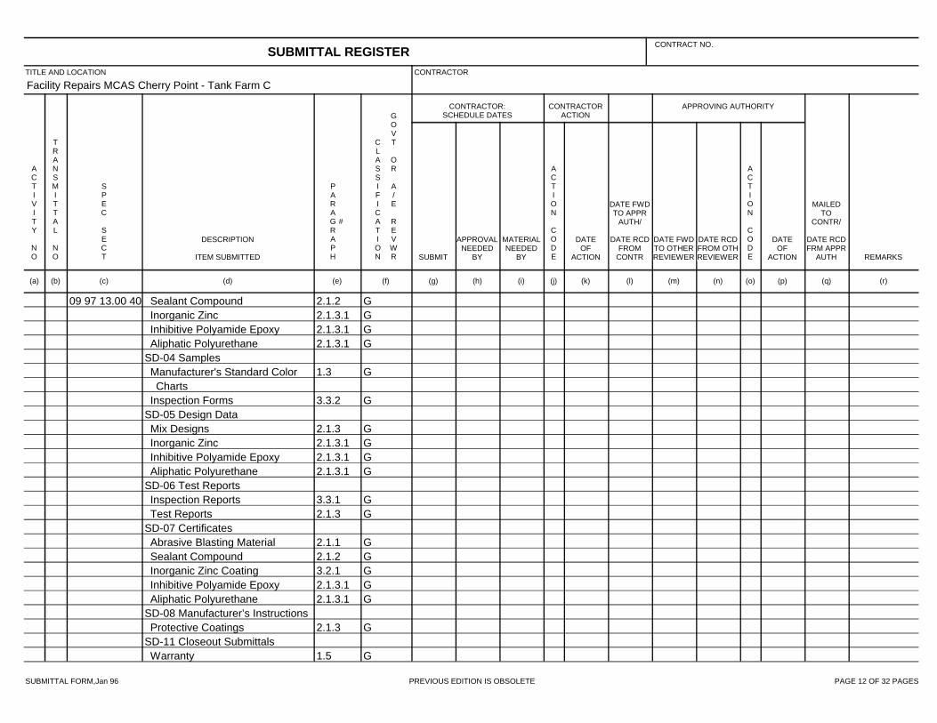
SUBMITTAL FORM,Jan 96 PREVIOUS EDITION IS OBSOLETE PAGE 12 OF 32 PAGES
Facility Repairs MCAS Cherry Point - Tank Farm C
09 97 13.00 40 2.1.2 GSealant Compound2.1.3.1 GInorganic Zinc2.1.3.1 GInhibitive Polyamide Epoxy2.1.3.1 GAliphatic Polyurethane
SD-04 Samples1.3 GManufacturer's Standard Color
Charts3.3.2 GInspection Forms
SD-05 Design Data2.1.3 GMix Designs2.1.3.1 GInorganic Zinc2.1.3.1 GInhibitive Polyamide Epoxy2.1.3.1 GAliphatic Polyurethane
SD-06 Test Reports3.3.1 GInspection Reports2.1.3 GTest Reports
SD-07 Certificates2.1.1 GAbrasive Blasting Material2.1.2 GSealant Compound3.2.1 GInorganic Zinc Coating2.1.3.1 GInhibitive Polyamide Epoxy2.1.3.1 GAliphatic Polyurethane
SD-08 Manufacturer’s Instructions2.1.3 GProtective Coatings
SD-11 Closeout Submittals1.5 GWarranty
SUBMITTAL REGISTERCONTRACT NO.
TITLE AND LOCATION CONTRACTOR
CONTRACTOR:SCHEDULE DATES
CONTRACTORACTION
APPROVING AUTHORITY
ACTIVITY NO
TRANSMITTAL NO
SPEC SECT
DESCRIPTION
ITEM SUBMITTED
PARAGRAPH
#
CLASSIFICATION
GOVT OR A/E REVWR SUBMIT
APPROVALNEEDED
BY
MATERIALNEEDED
BY
ACTION CODE
DATEOF
ACTION
DATE FWDTO APPR
AUTH/
DATE RCDFROM
CONTR
DATE FWDTO OTHERREVIEWER
DATE RCDFROM OTHREVIEWER
ACTION CODE
DATEOF
ACTION
MAILEDTO
CONTR/
DATE RCDFRM APPR
AUTH REMARKS
(a) (b) (c) (d) (e) (f) (g) (h) (i) (j) (k) (l) (m) (n) (o) (p) (q) (r)

SUBMITTAL FORM,Jan 96 PREVIOUS EDITION IS OBSOLETE PAGE 13 OF 32 PAGES
Facility Repairs MCAS Cherry Point - Tank Farm C
09 97 13.27 SD-05 Design Data1.4.4.1Containment System
SD-06 Test Reports1.4.5.1 GJoint Sealant Qualification Test
Reports1.4.5.2 GCoatings Qualification Test
Reports1.4.5.3 GMetallic Abrasive Qualification
Test Reports3.1.3 GCoating Sample Test Reports3.1.4 GAbrasive Sample Test Reports3.8.2.2 GInspection Report Forms3.8.2.3Daily Inspection Reports1.4.5.4Recycled Metallic Abrasive Field
Test Reports (Daily and Weekly)SD-07 Certificates
1.4.1Contract Errors, Omissions, andOther Discrepancies
1.4.2.1Corrective Action Procedures1.4.3 GCoating Work Plan1.4.6.1 GQualifications of Certified
Industrial Hygienist (CIH)1.4.6.5 GQualifications Of Individuals
Performing Abrasive Blasting
SUBMITTAL REGISTERCONTRACT NO.
TITLE AND LOCATION CONTRACTOR
CONTRACTOR:SCHEDULE DATES
CONTRACTORACTION
APPROVING AUTHORITY
ACTIVITY NO
TRANSMITTAL NO
SPEC SECT
DESCRIPTION
ITEM SUBMITTED
PARAGRAPH
#
CLASSIFICATION
GOVT OR A/E REVWR SUBMIT
APPROVALNEEDED
BY
MATERIALNEEDED
BY
ACTION CODE
DATEOF
ACTION
DATE FWDTO APPR
AUTH/
DATE RCDFROM
CONTR
DATE FWDTO OTHERREVIEWER
DATE RCDFROM OTHREVIEWER
ACTION CODE
DATEOF
ACTION
MAILEDTO
CONTR/
DATE RCDFRM APPR
AUTH REMARKS
(a) (b) (c) (d) (e) (f) (g) (h) (i) (j) (k) (l) (m) (n) (o) (p) (q) (r)

SUBMITTAL FORM,Jan 96 PREVIOUS EDITION IS OBSOLETE PAGE 14 OF 32 PAGES
Facility Repairs MCAS Cherry Point - Tank Farm C
09 97 13.27 1.4.6.2 GQualifications of CertifiedProtective Coatings Specialist(PCS)
1.4.6.3 GQualifications of CoatingInspection Company
1.4.6.4 GQualifications of QC SpecialistCoating Inspector
1.4.6.6 GQualifications of TestingLaboratory for Coatings
1.4.6.7 GQualifications of TestingLaboratory for Abrasive
1.4.6.8 GQualifications of CoatingContractors
1.4.6.9Joint Sealant Materials1.4.6.10 GCoating Materials1.4.6.11 GCoating System Component
Compatibility1.4.6.12 GNon-metallic Abrasive1.4.6.13 GMetallic Abrasive
SD-08 Manufacturer’s Instructions1.5.1Joint Sealant Instructions1.5.2Coating System Instructions
SD-11 Closeout Submittals3.5.6Disposal of Used Abrasive3.8.2.4 GInspection Logbook
22 00 00 SD-03 Product Data
SUBMITTAL REGISTERCONTRACT NO.
TITLE AND LOCATION CONTRACTOR
CONTRACTOR:SCHEDULE DATES
CONTRACTORACTION
APPROVING AUTHORITY
ACTIVITY NO
TRANSMITTAL NO
SPEC SECT
DESCRIPTION
ITEM SUBMITTED
PARAGRAPH
#
CLASSIFICATION
GOVT OR A/E REVWR SUBMIT
APPROVALNEEDED
BY
MATERIALNEEDED
BY
ACTION CODE
DATEOF
ACTION
DATE FWDTO APPR
AUTH/
DATE RCDFROM
CONTR
DATE FWDTO OTHERREVIEWER
DATE RCDFROM OTHREVIEWER
ACTION CODE
DATEOF
ACTION
MAILEDTO
CONTR/
DATE RCDFRM APPR
AUTH REMARKS
(a) (b) (c) (d) (e) (f) (g) (h) (i) (j) (k) (l) (m) (n) (o) (p) (q) (r)

SUBMITTAL FORM,Jan 96 PREVIOUS EDITION IS OBSOLETE PAGE 15 OF 32 PAGES
Facility Repairs MCAS Cherry Point - Tank Farm C
22 00 00 2.4Fixtures2.4.1 GPackaged Emergency Shower
Unit1.5.1Welding
SD-06 Test Reports3.3Tests, Flushing and Disinfection
SD-07 Certificates1.3Materials and Equipment2.1.1Bolts
SD-10 Operation and MaintenanceData
3.3.1 GPlumbing System26 08 00 SD-06 Test Reports
3.1 GAcceptance tests and inspectionsSD-07 Certificates
1.4.1 GQualifications1.4.3 GAcceptance test and inspections
procedure26 20 00 SD-02 Shop Drawings
2.8 GPanelboardsSD-03 Product Data
2.8.3 GCircuit breakers2.7 GEmergency Shutdown Push
Button2.6 GSwitches2.15 GSurge protective devices
SUBMITTAL REGISTERCONTRACT NO.
TITLE AND LOCATION CONTRACTOR
CONTRACTOR:SCHEDULE DATES
CONTRACTORACTION
APPROVING AUTHORITY
ACTIVITY NO
TRANSMITTAL NO
SPEC SECT
DESCRIPTION
ITEM SUBMITTED
PARAGRAPH
#
CLASSIFICATION
GOVT OR A/E REVWR SUBMIT
APPROVALNEEDED
BY
MATERIALNEEDED
BY
ACTION CODE
DATEOF
ACTION
DATE FWDTO APPR
AUTH/
DATE RCDFROM
CONTR
DATE FWDTO OTHERREVIEWER
DATE RCDFROM OTHREVIEWER
ACTION CODE
DATEOF
ACTION
MAILEDTO
CONTR/
DATE RCDFRM APPR
AUTH REMARKS
(a) (b) (c) (d) (e) (f) (g) (h) (i) (j) (k) (l) (m) (n) (o) (p) (q) (r)

SUBMITTAL FORM,Jan 96 PREVIOUS EDITION IS OBSOLETE PAGE 16 OF 32 PAGES
Facility Repairs MCAS Cherry Point - Tank Farm C
26 20 00 SD-06 Test Reports3.5.2 G600-volt wiring test3.5.3 GGrounding system test
26 32 13.00 20 SD-02 Shop Drawings1.5.2.1 GEngine-Generator set and
auxiliary equipmentSD-03 Product Data
1.3.1 GEngine-generator set data1.3.2 GEngine-generator set efficiencies1.3.3 GDiesel engine data1.3.4 GGenerator and exciter data2.1 GDiesel engine-generator set2.2 GAuxiliary systems and equipment2.2.7 GRemote alarm annunciator
SD-05 Design Data1.3.5 GCapacity calculations for
engine-generator set1.3.6 GCalculations for brake mean
effective pressure1.3.7 GTorsional vibration stress analysis
computations1.3.8 GCapacity calculations for batteries
SD-06 Test Reports3.5.1 GAcceptance checks and tests3.5.2 GFunctional acceptance tests
SUBMITTAL REGISTERCONTRACT NO.
TITLE AND LOCATION CONTRACTOR
CONTRACTOR:SCHEDULE DATES
CONTRACTORACTION
APPROVING AUTHORITY
ACTIVITY NO
TRANSMITTAL NO
SPEC SECT
DESCRIPTION
ITEM SUBMITTED
PARAGRAPH
#
CLASSIFICATION
GOVT OR A/E REVWR SUBMIT
APPROVALNEEDED
BY
MATERIALNEEDED
BY
ACTION CODE
DATEOF
ACTION
DATE FWDTO APPR
AUTH/
DATE RCDFROM
CONTR
DATE FWDTO OTHERREVIEWER
DATE RCDFROM OTHREVIEWER
ACTION CODE
DATEOF
ACTION
MAILEDTO
CONTR/
DATE RCDFRM APPR
AUTH REMARKS
(a) (b) (c) (d) (e) (f) (g) (h) (i) (j) (k) (l) (m) (n) (o) (p) (q) (r)

SUBMITTAL FORM,Jan 96 PREVIOUS EDITION IS OBSOLETE PAGE 17 OF 32 PAGES
Facility Repairs MCAS Cherry Point - Tank Farm C
26 32 13.00 20 3.4.4 GFunctional acceptance testprocedure
SD-07 Certificates1.5.3 GVibration isolation system1.5.4 GFuel system3.3 GStart-up engineer3.6.1 GInstructor's
SD-09 Manufacturer’s FieldReports
2.6.1 GEngine tests2.6.2 GGenerator tests2.6.3 GAssembled engine-generator set
tests1.6 GIBC Seismic Certificate of
ComplianceSD-10 Operation and MaintenanceData
2.1 GDiesel engine-generator set3.4.3 GPreliminary assembled operation
and maintenance manualsSD-11 Closeout Submittals
1.9.2 GPosted operating instructions3.6.2 GTraining plan
26 36 23.00 20 SD-02 Shop Drawings1.4.2 GAutomatic Transfer Switch
Drawings
SUBMITTAL REGISTERCONTRACT NO.
TITLE AND LOCATION CONTRACTOR
CONTRACTOR:SCHEDULE DATES
CONTRACTORACTION
APPROVING AUTHORITY
ACTIVITY NO
TRANSMITTAL NO
SPEC SECT
DESCRIPTION
ITEM SUBMITTED
PARAGRAPH
#
CLASSIFICATION
GOVT OR A/E REVWR SUBMIT
APPROVALNEEDED
BY
MATERIALNEEDED
BY
ACTION CODE
DATEOF
ACTION
DATE FWDTO APPR
AUTH/
DATE RCDFROM
CONTR
DATE FWDTO OTHERREVIEWER
DATE RCDFROM OTHREVIEWER
ACTION CODE
DATEOF
ACTION
MAILEDTO
CONTR/
DATE RCDFRM APPR
AUTH REMARKS
(a) (b) (c) (d) (e) (f) (g) (h) (i) (j) (k) (l) (m) (n) (o) (p) (q) (r)

SUBMITTAL FORM,Jan 96 PREVIOUS EDITION IS OBSOLETE PAGE 18 OF 32 PAGES
Facility Repairs MCAS Cherry Point - Tank Farm C
26 36 23.00 20 SD-03 Product Data2.1 GAutomatic Transfer Switches
SD-06 Test Reports3.3.1 GAcceptance Checks and Tests3.3.2 GFunctional Acceptance Tests
SD-07 Certificates1.4.1 GProof of Listing
SD-10 Operation and MaintenanceData
2.1 GAutomatic Transfer Switches26 41 00 SD-02 Shop Drawings
1.4.1.1 GOverall lightning protectionsystem
1.4.1.2 GEach major componentSD-06 Test Reports
1.4.3 GLightning Protection andGrounding System Test Plan
3.4.1 GLightning Protection andGrounding System Test
SD-07 Certificates1.2.3 GLightning Protection System
Installers Documentation1.4.2 GComponent UL Listed and
Labeled1.4.4 GLightning protection system
inspection certificate
SUBMITTAL REGISTERCONTRACT NO.
TITLE AND LOCATION CONTRACTOR
CONTRACTOR:SCHEDULE DATES
CONTRACTORACTION
APPROVING AUTHORITY
ACTIVITY NO
TRANSMITTAL NO
SPEC SECT
DESCRIPTION
ITEM SUBMITTED
PARAGRAPH
#
CLASSIFICATION
GOVT OR A/E REVWR SUBMIT
APPROVALNEEDED
BY
MATERIALNEEDED
BY
ACTION CODE
DATEOF
ACTION
DATE FWDTO APPR
AUTH/
DATE RCDFROM
CONTR
DATE FWDTO OTHERREVIEWER
DATE RCDFROM OTHREVIEWER
ACTION CODE
DATEOF
ACTION
MAILEDTO
CONTR/
DATE RCDFRM APPR
AUTH REMARKS
(a) (b) (c) (d) (e) (f) (g) (h) (i) (j) (k) (l) (m) (n) (o) (p) (q) (r)

SUBMITTAL FORM,Jan 96 PREVIOUS EDITION IS OBSOLETE PAGE 19 OF 32 PAGES
Facility Repairs MCAS Cherry Point - Tank Farm C
26 41 00 3.1.1 GRoof manufacturer's warranty27 10 00 SD-03 Product Data
2.3 GTelecommunications cabling2.4 GTelecommunications
outlet/connector assembliesSD-06 Test Reports
3.4.1 GTelecommunications cablingtesting
SD-07 Certificates1.6.1.1 GTelecommunications Contractor1.6.1.2 GManufacturer Qualifications1.6.2 GTest plan
SD-09 Manufacturer’s FieldReports
2.8.1 GFactory reel testsSD-10 Operation and MaintenanceData
1.10.1 GTelecommunications cabling andpathway system
28 10 05 SD-03 Product Data2.2.1 GCameras2.2.1.2 GCamera Lenses2.2.1.3 GCamera Housing and Mounts
31 11 00 SD-03 Product Data3.5.1 GNonsaleable Materials
31 23 00.00 20 SD-01 Preconstruction Submittals
SUBMITTAL REGISTERCONTRACT NO.
TITLE AND LOCATION CONTRACTOR
CONTRACTOR:SCHEDULE DATES
CONTRACTORACTION
APPROVING AUTHORITY
ACTIVITY NO
TRANSMITTAL NO
SPEC SECT
DESCRIPTION
ITEM SUBMITTED
PARAGRAPH
#
CLASSIFICATION
GOVT OR A/E REVWR SUBMIT
APPROVALNEEDED
BY
MATERIALNEEDED
BY
ACTION CODE
DATEOF
ACTION
DATE FWDTO APPR
AUTH/
DATE RCDFROM
CONTR
DATE FWDTO OTHERREVIEWER
DATE RCDFROM OTHREVIEWER
ACTION CODE
DATEOF
ACTION
MAILEDTO
CONTR/
DATE RCDFRM APPR
AUTH REMARKS
(a) (b) (c) (d) (e) (f) (g) (h) (i) (j) (k) (l) (m) (n) (o) (p) (q) (r)

SUBMITTAL FORM,Jan 96 PREVIOUS EDITION IS OBSOLETE PAGE 20 OF 32 PAGES
Facility Repairs MCAS Cherry Point - Tank Farm C
31 23 00.00 20 1.8.1Shoring and Sheeting Plan1.8.2Dewatering work plan
SD-06 Test ReportsGBorrow Site Testing
3.13.2.1Fill and backfill3.13.2.2Density tests3.13.2.3Moisture Content Tests
32 01 19.61 SD-03 Product Data2.1.1Joint sealant
SD-04 Samples3.1.1Joint filler2.1.3.2Separating tape2.1.3.1backer rod2.1.1Joint sealant
SD-06 Test Reports2.1.1Joint sealant
SD-07 Certificates1.6Equipment list
SD-08 Manufacturer’s Instructions2.1.1Joint sealant
32 01 29.61 SD-03 Product Data2.1.4.1 GMix Design2.1.10 GProprietary Cementitious
ProductsSD-05 Design Data
1.3.1 GConcrete Mix Design
SUBMITTAL REGISTERCONTRACT NO.
TITLE AND LOCATION CONTRACTOR
CONTRACTOR:SCHEDULE DATES
CONTRACTORACTION
APPROVING AUTHORITY
ACTIVITY NO
TRANSMITTAL NO
SPEC SECT
DESCRIPTION
ITEM SUBMITTED
PARAGRAPH
#
CLASSIFICATION
GOVT OR A/E REVWR SUBMIT
APPROVALNEEDED
BY
MATERIALNEEDED
BY
ACTION CODE
DATEOF
ACTION
DATE FWDTO APPR
AUTH/
DATE RCDFROM
CONTR
DATE FWDTO OTHERREVIEWER
DATE RCDFROM OTHREVIEWER
ACTION CODE
DATEOF
ACTION
MAILEDTO
CONTR/
DATE RCDFRM APPR
AUTH REMARKS
(a) (b) (c) (d) (e) (f) (g) (h) (i) (j) (k) (l) (m) (n) (o) (p) (q) (r)

SUBMITTAL FORM,Jan 96 PREVIOUS EDITION IS OBSOLETE PAGE 21 OF 32 PAGES
Facility Repairs MCAS Cherry Point - Tank Farm C
32 01 29.61 SD-06 Test Reports1.3.1Test Results1.3.1.2Gradation2.1.1.4Gradation1.3.1.1Cement2.1.4.1Slump2.1.4.1Air Content3.4.2Strength1.3.2Mixer Calibration and Efficiency
SD-07 Certificates1.3.1.1Cement1.3.1.2Aggregate2.1.3Admixtures3.6.3Absorbent curing material2.1.5.2Waterproof Sheet2.1.8Joint Filler2.1.7Joint Sealant
32 11 23 SD-03 Product Data2.1Plant, Equipment, and Tools
SD-06 Test Reports1.4 GSampling and Testing1.4.2.4 GField Density Tests
32 12 10 SD-06 Test Reports3.7Sampling and Testing
32 12 17 SD-04 SamplesBituminous pavement
SUBMITTAL REGISTERCONTRACT NO.
TITLE AND LOCATION CONTRACTOR
CONTRACTOR:SCHEDULE DATES
CONTRACTORACTION
APPROVING AUTHORITY
ACTIVITY NO
TRANSMITTAL NO
SPEC SECT
DESCRIPTION
ITEM SUBMITTED
PARAGRAPH
#
CLASSIFICATION
GOVT OR A/E REVWR SUBMIT
APPROVALNEEDED
BY
MATERIALNEEDED
BY
ACTION CODE
DATEOF
ACTION
DATE FWDTO APPR
AUTH/
DATE RCDFROM
CONTR
DATE FWDTO OTHERREVIEWER
DATE RCDFROM OTHREVIEWER
ACTION CODE
DATEOF
ACTION
MAILEDTO
CONTR/
DATE RCDFRM APPR
AUTH REMARKS
(a) (b) (c) (d) (e) (f) (g) (h) (i) (j) (k) (l) (m) (n) (o) (p) (q) (r)

SUBMITTAL FORM,Jan 96 PREVIOUS EDITION IS OBSOLETE PAGE 22 OF 32 PAGES
Facility Repairs MCAS Cherry Point - Tank Farm C
32 12 17 SD-05 Design Data1.3.2Job-mix formula2.2ASPHALT CEMENT BINDER2.3MIX DESIGN
SD-06 Test Reports2.4.1Specific gravity test of asphalt2.4.1Coarse aggregate tests2.4.1Weight of slag test2.4.1Percent of crushed pieces in
gravel2.4.1Fine aggregate tests2.4.1Specific gravity of mineral filler2.4.1Bituminous mixture tests3.5.2.1Aggregates tests3.5.2.2Bituminous mix tests3.5.2.3Pavement courses
32 13 13.06 SD-03 Product Data2.1.6 GCuring Materials2.1.4 GAdmixtures2.1.5.1 GDowel2.1.1 GCementitious Materials2.1.3 GAggregate
SD-04 Samples1.5.5Field-Constructed Mockup
SD-05 Design Data2.3 GMix Design
SUBMITTAL REGISTERCONTRACT NO.
TITLE AND LOCATION CONTRACTOR
CONTRACTOR:SCHEDULE DATES
CONTRACTORACTION
APPROVING AUTHORITY
ACTIVITY NO
TRANSMITTAL NO
SPEC SECT
DESCRIPTION
ITEM SUBMITTED
PARAGRAPH
#
CLASSIFICATION
GOVT OR A/E REVWR SUBMIT
APPROVALNEEDED
BY
MATERIALNEEDED
BY
ACTION CODE
DATEOF
ACTION
DATE FWDTO APPR
AUTH/
DATE RCDFROM
CONTR
DATE FWDTO OTHERREVIEWER
DATE RCDFROM OTHREVIEWER
ACTION CODE
DATEOF
ACTION
MAILEDTO
CONTR/
DATE RCDFRM APPR
AUTH REMARKS
(a) (b) (c) (d) (e) (f) (g) (h) (i) (j) (k) (l) (m) (n) (o) (p) (q) (r)

SUBMITTAL FORM,Jan 96 PREVIOUS EDITION IS OBSOLETE PAGE 23 OF 32 PAGES
Facility Repairs MCAS Cherry Point - Tank Farm C
32 13 13.06 SD-06 Test Reports2.1.3 GAggregate3.7.2 GConcrete Slump Tests3.7.4 GAir Content Tests3.7.3 GFlexural Strength Tests2.1.1 GCementitious Materials
SD-07 Certificates1.5.1 GReady-mixed Concrete Plant1.5.4 GBatch Tickets2.1.1 GCementitious Materials
32 31 13 SD-02 Shop Drawings1.3 GFence Assembly3.16.1 GLocation of Gate, Corner, End,
and Pull Posts1.3 GGate Assembly2.18 GGate Hardware and Accessories1.3 GErection/Installation Drawings
SD-03 Product Data1.3 GFence Assembly1.3 GGate Assembly2.18 GGate Hardware and Accessories2.2 GZinc Coating2.13 GStretcher Bars2.21 GConcrete
SD-04 Samples2.3 GFabric
SUBMITTAL REGISTERCONTRACT NO.
TITLE AND LOCATION CONTRACTOR
CONTRACTOR:SCHEDULE DATES
CONTRACTORACTION
APPROVING AUTHORITY
ACTIVITY NO
TRANSMITTAL NO
SPEC SECT
DESCRIPTION
ITEM SUBMITTED
PARAGRAPH
#
CLASSIFICATION
GOVT OR A/E REVWR SUBMIT
APPROVALNEEDED
BY
MATERIALNEEDED
BY
ACTION CODE
DATEOF
ACTION
DATE FWDTO APPR
AUTH/
DATE RCDFROM
CONTR
DATE FWDTO OTHERREVIEWER
DATE RCDFROM OTHREVIEWER
ACTION CODE
DATEOF
ACTION
MAILEDTO
CONTR/
DATE RCDFRM APPR
AUTH REMARKS
(a) (b) (c) (d) (e) (f) (g) (h) (i) (j) (k) (l) (m) (n) (o) (p) (q) (r)

SUBMITTAL FORM,Jan 96 PREVIOUS EDITION IS OBSOLETE PAGE 24 OF 32 PAGES
Facility Repairs MCAS Cherry Point - Tank Farm C
32 31 13 2.5 GPosts2.5 GBraces2.6 GLine Posts2.8 GSleeves2.9 GTop Rail2.12 GTension Wire2.13 GStretcher Bars2.16 GGate Posts2.18 GGate Hardware and Accessories2.23 GPadlocks2.20 GWire Ties
SD-08 Manufacturer’s Instructions1.3 GFence Assembly1.3 GGate Assembly1.3 GHardware Assembly1.3 GAccessories
33 08 55 SD-01 Preconstruction Submittals1.5 GCommissioning Plan
SD-06 Test Reports3.4.2 GPiping Flushing Checklist1.7 GCommissioning Report
SD-07 Certificates1.6Certification of Completion1.8Disposal of Waste Materials
33 11 00 SD-03 Product Data
SUBMITTAL REGISTERCONTRACT NO.
TITLE AND LOCATION CONTRACTOR
CONTRACTOR:SCHEDULE DATES
CONTRACTORACTION
APPROVING AUTHORITY
ACTIVITY NO
TRANSMITTAL NO
SPEC SECT
DESCRIPTION
ITEM SUBMITTED
PARAGRAPH
#
CLASSIFICATION
GOVT OR A/E REVWR SUBMIT
APPROVALNEEDED
BY
MATERIALNEEDED
BY
ACTION CODE
DATEOF
ACTION
DATE FWDTO APPR
AUTH/
DATE RCDFROM
CONTR
DATE FWDTO OTHERREVIEWER
DATE RCDFROM OTHREVIEWER
ACTION CODE
DATEOF
ACTION
MAILEDTO
CONTR/
DATE RCDFRM APPR
AUTH REMARKS
(a) (b) (c) (d) (e) (f) (g) (h) (i) (j) (k) (l) (m) (n) (o) (p) (q) (r)

SUBMITTAL FORM,Jan 96 PREVIOUS EDITION IS OBSOLETE PAGE 25 OF 32 PAGES
Facility Repairs MCAS Cherry Point - Tank Farm C
33 11 00 2.2 GPipe, Fittings, Joints andCouplings
2.3 GValves2.3.4 GIndicator Posts2.3.5 GValve Boxes2.4.1 GHydrants2.5.1 GTapping Sleeves2.5.3.1 GCorporation Stops
SD-06 Test Reports3.2.6 GBacteriological Samples
SD-07 Certificates2.2Pipe, Fittings, Joints and
Couplings2.2.1.1Lining2.2.1.1Lining2.2.2.1.1Lining for Fittings2.3Valves2.4.1Hydrants3.2.6Disinfection Procedures
SD-08 Manufacturer’s Instructions3.2.1Manufacturer's Instructions
33 40 00 SD-03 Product Data2.7Containment Valves3.3Placing Pipe
SD-04 Samples
SUBMITTAL REGISTERCONTRACT NO.
TITLE AND LOCATION CONTRACTOR
CONTRACTOR:SCHEDULE DATES
CONTRACTORACTION
APPROVING AUTHORITY
ACTIVITY NO
TRANSMITTAL NO
SPEC SECT
DESCRIPTION
ITEM SUBMITTED
PARAGRAPH
#
CLASSIFICATION
GOVT OR A/E REVWR SUBMIT
APPROVALNEEDED
BY
MATERIALNEEDED
BY
ACTION CODE
DATEOF
ACTION
DATE FWDTO APPR
AUTH/
DATE RCDFROM
CONTR
DATE FWDTO OTHERREVIEWER
DATE RCDFROM OTHREVIEWER
ACTION CODE
DATEOF
ACTION
MAILEDTO
CONTR/
DATE RCDFRM APPR
AUTH REMARKS
(a) (b) (c) (d) (e) (f) (g) (h) (i) (j) (k) (l) (m) (n) (o) (p) (q) (r)

SUBMITTAL FORM,Jan 96 PREVIOUS EDITION IS OBSOLETE PAGE 26 OF 32 PAGES
Facility Repairs MCAS Cherry Point - Tank Farm C
33 40 00 2.1Pipe for Culverts and StormDrains
SD-07 Certificates3.8Pipeline Testing2.6Hydrostatic Test on Watertight
Joints3.7.5Determination of Density2.3.4Frame and Cover for Gratings
33 52 43.13 SD-03 Product Data2.1.4 GFittings2.4.1 GFlexible Ball Joints2.1.1 GCarbon Steel Piping2.1.2 GFlexible Pipe
GStrainers2.5 GFlexible Hoses3.6.2 GProtective Coatings2.4.4 GSample Connections
GIsolating Gasket Kits2.1.6Gaskets - Spiral Wound2.1.2.14 GTransition Sumps
SD-06 Test Reports3.9.1Pneumatic Test3.9.1.2Hydrostatic Test
SD-07 Certificates3.5Welding2.1.4Fittings
SUBMITTAL REGISTERCONTRACT NO.
TITLE AND LOCATION CONTRACTOR
CONTRACTOR:SCHEDULE DATES
CONTRACTORACTION
APPROVING AUTHORITY
ACTIVITY NO
TRANSMITTAL NO
SPEC SECT
DESCRIPTION
ITEM SUBMITTED
PARAGRAPH
#
CLASSIFICATION
GOVT OR A/E REVWR SUBMIT
APPROVALNEEDED
BY
MATERIALNEEDED
BY
ACTION CODE
DATEOF
ACTION
DATE FWDTO APPR
AUTH/
DATE RCDFROM
CONTR
DATE FWDTO OTHERREVIEWER
DATE RCDFROM OTHREVIEWER
ACTION CODE
DATEOF
ACTION
MAILEDTO
CONTR/
DATE RCDFRM APPR
AUTH REMARKS
(a) (b) (c) (d) (e) (f) (g) (h) (i) (j) (k) (l) (m) (n) (o) (p) (q) (r)

SUBMITTAL FORM,Jan 96 PREVIOUS EDITION IS OBSOLETE PAGE 27 OF 32 PAGES
Facility Repairs MCAS Cherry Point - Tank Farm C
33 52 43.13 Isolating Gasket Kits3.4.7Survey Final Elevations
SD-10 Operation and MaintenanceData
1.2 GOperation and MaintenanceManuals
33 52 80 SD-03 Product DataGExternal Pipe CoatingGField-Applied External Pipe
CoatingSD-06 Test Reports
GQualification Testing3.3.2.2Inspection Report Forms3.3.2.3Daily Inspection Reports
SD-07 Certificates1.4.1 GContract Errors, Omissions, and
Other Discrepancies1.4.2.1 GCorrective Action Procedures1.4.3 GCoating Work Plan1.4.4.1 GQualifications of Certified
Industrial Hygienist (CIH)1.4.4.8 GQualifications of Pipe Coating
Shop1.4.4.2 GQualifications of Certified
Protective Coatings Specialist(PCS)
SUBMITTAL REGISTERCONTRACT NO.
TITLE AND LOCATION CONTRACTOR
CONTRACTOR:SCHEDULE DATES
CONTRACTORACTION
APPROVING AUTHORITY
ACTIVITY NO
TRANSMITTAL NO
SPEC SECT
DESCRIPTION
ITEM SUBMITTED
PARAGRAPH
#
CLASSIFICATION
GOVT OR A/E REVWR SUBMIT
APPROVALNEEDED
BY
MATERIALNEEDED
BY
ACTION CODE
DATEOF
ACTION
DATE FWDTO APPR
AUTH/
DATE RCDFROM
CONTR
DATE FWDTO OTHERREVIEWER
DATE RCDFROM OTHREVIEWER
ACTION CODE
DATEOF
ACTION
MAILEDTO
CONTR/
DATE RCDFRM APPR
AUTH REMARKS
(a) (b) (c) (d) (e) (f) (g) (h) (i) (j) (k) (l) (m) (n) (o) (p) (q) (r)

SUBMITTAL FORM,Jan 96 PREVIOUS EDITION IS OBSOLETE PAGE 28 OF 32 PAGES
Facility Repairs MCAS Cherry Point - Tank Farm C
33 52 80 1.4.4.3 GQualifications of CoatingInspection Company for FieldCoating
1.4.4.4 GQualifications of CoatingInspector for Field Coating
1.4.4.5 GQualifications Of IndividualsPerforming Abrasive Blasting forField Coating
1.4.4.6 GQualifications of IndividualsPerforming Coating Application forField Coating
1.4.4.6 GQualifications of IndividualsPerforming Coating Application forField Coating
1.4.4.7 GQualifications of IndividualsOperating Plural ComponentEquipment (Pump Tenders) forField Coating
1.4.4.9 GQualifications of CoatingContractors
SD-11 Closeout Submittals3.3.2.4Inspection Logbook
33 52 90.00 20 SD-01 Preconstruction Submittals1.6 GWelding procedure qualification3.1 GWelding Operations
SD-02 Shop Drawings
SUBMITTAL REGISTERCONTRACT NO.
TITLE AND LOCATION CONTRACTOR
CONTRACTOR:SCHEDULE DATES
CONTRACTORACTION
APPROVING AUTHORITY
ACTIVITY NO
TRANSMITTAL NO
SPEC SECT
DESCRIPTION
ITEM SUBMITTED
PARAGRAPH
#
CLASSIFICATION
GOVT OR A/E REVWR SUBMIT
APPROVALNEEDED
BY
MATERIALNEEDED
BY
ACTION CODE
DATEOF
ACTION
DATE FWDTO APPR
AUTH/
DATE RCDFROM
CONTR
DATE FWDTO OTHERREVIEWER
DATE RCDFROM OTHREVIEWER
ACTION CODE
DATEOF
ACTION
MAILEDTO
CONTR/
DATE RCDFRM APPR
AUTH REMARKS
(a) (b) (c) (d) (e) (f) (g) (h) (i) (j) (k) (l) (m) (n) (o) (p) (q) (r)

SUBMITTAL FORM,Jan 96 PREVIOUS EDITION IS OBSOLETE PAGE 29 OF 32 PAGES
Facility Repairs MCAS Cherry Point - Tank Farm C
33 52 90.00 20 1.6.2 GPOL Service PipingSD-06 Test Reports
3.2Examinations, Inspections andTests
SD-07 Certificates1.6 GQualifications
33 56 10 SD-02 Shop Drawings2.3.2Grounding and Bonding2.4 GAboveground Storage Tank
SD-03 Product Data2.4 GAboveground Storage Tank2.5 GTank Protective Coatings2.7 GAutomatic Level Alarm System2.8 GTank Gauges2.9Water Draw-Off Pump
SD-06 Test Reports3.2.1 GAboveground Storage Tank
Tightness Tests3.2.2Tank Manufacturer's Tests3.4Tank Fill Tests
SD-07 Certificates1.3.1 GContractor Qualifications1.3.2.1Permitting1.3.2.2Registration1.3.2.3Licensed Personnel3.3Demonstrations
SUBMITTAL REGISTERCONTRACT NO.
TITLE AND LOCATION CONTRACTOR
CONTRACTOR:SCHEDULE DATES
CONTRACTORACTION
APPROVING AUTHORITY
ACTIVITY NO
TRANSMITTAL NO
SPEC SECT
DESCRIPTION
ITEM SUBMITTED
PARAGRAPH
#
CLASSIFICATION
GOVT OR A/E REVWR SUBMIT
APPROVALNEEDED
BY
MATERIALNEEDED
BY
ACTION CODE
DATEOF
ACTION
DATE FWDTO APPR
AUTH/
DATE RCDFROM
CONTR
DATE FWDTO OTHERREVIEWER
DATE RCDFROM OTHREVIEWER
ACTION CODE
DATEOF
ACTION
MAILEDTO
CONTR/
DATE RCDFRM APPR
AUTH REMARKS
(a) (b) (c) (d) (e) (f) (g) (h) (i) (j) (k) (l) (m) (n) (o) (p) (q) (r)

SUBMITTAL FORM,Jan 96 PREVIOUS EDITION IS OBSOLETE PAGE 30 OF 32 PAGES
Facility Repairs MCAS Cherry Point - Tank Farm C
33 56 10 SD-08 Manufacturer’s Instructions2.4Aboveground Storage Tank2.7Automatic Level Alarm System2.8Tank Gauges
SD-10 Operation and MaintenanceData
2.4 GAboveground Storage Tank2.7 GAutomatic Level Alarm System2.8 GTank Gauges
33 57 00 SD-02 Shop Drawings2.2.5Grounding and Bonding
SD-03 Product Data2.3Tank Truck off-loading Cabinet2.4.3Dry-Break Coupler
SD-07 Certificates3.3Demonstrations
SD-10 Operation and MaintenanceData
2.3 GTank Truck Off-loading CabinetGNon-Aviation Fuel Hose
33 65 00 SD-03 Product Data2.1.1Cleaning agents2.2Gasoline-oil-resisting rubber
gloves and boots2.2Cotton coveralls and hard hat2.2Respiratory protective equipment
SUBMITTAL REGISTERCONTRACT NO.
TITLE AND LOCATION CONTRACTOR
CONTRACTOR:SCHEDULE DATES
CONTRACTORACTION
APPROVING AUTHORITY
ACTIVITY NO
TRANSMITTAL NO
SPEC SECT
DESCRIPTION
ITEM SUBMITTED
PARAGRAPH
#
CLASSIFICATION
GOVT OR A/E REVWR SUBMIT
APPROVALNEEDED
BY
MATERIALNEEDED
BY
ACTION CODE
DATEOF
ACTION
DATE FWDTO APPR
AUTH/
DATE RCDFROM
CONTR
DATE FWDTO OTHERREVIEWER
DATE RCDFROM OTHREVIEWER
ACTION CODE
DATEOF
ACTION
MAILEDTO
CONTR/
DATE RCDFRM APPR
AUTH REMARKS
(a) (b) (c) (d) (e) (f) (g) (h) (i) (j) (k) (l) (m) (n) (o) (p) (q) (r)

SUBMITTAL FORM,Jan 96 PREVIOUS EDITION IS OBSOLETE PAGE 31 OF 32 PAGES
Facility Repairs MCAS Cherry Point - Tank Farm C
33 65 00 2.2Disinfectant2.1.2.1Abrasive for blasting
SD-06 Test Reports1.4.9.1Blasting abrasive1.4.9.1Tank contents1.4.9.2 GMonitoring Results
SD-07 Certificates1.4.8.1Qualifications of Marine Chemist1.4.8.2Qualifications of Certified
Industrial Hygienist (CIH)1.4.8.3Testing laboratory1.4.8.4Safety plan1.4.8.5Work plan1.4.8.6Hazardous waste disposal plan1.4.8.7Tank certification of safety3.5.5 GPlan for pretreatment1.4.8.4Training certification2.2Respiratory protective equipment2.2Breathing-air supply source2.2Combustible gas indicator2.2Velometers2.2Lighting2.2First aid kit1.6.1exhaust
SD-08 Manufacturer’s Instructions2.1.1cleaning agents
SUBMITTAL REGISTERCONTRACT NO.
TITLE AND LOCATION CONTRACTOR
CONTRACTOR:SCHEDULE DATES
CONTRACTORACTION
APPROVING AUTHORITY
ACTIVITY NO
TRANSMITTAL NO
SPEC SECT
DESCRIPTION
ITEM SUBMITTED
PARAGRAPH
#
CLASSIFICATION
GOVT OR A/E REVWR SUBMIT
APPROVALNEEDED
BY
MATERIALNEEDED
BY
ACTION CODE
DATEOF
ACTION
DATE FWDTO APPR
AUTH/
DATE RCDFROM
CONTR
DATE FWDTO OTHERREVIEWER
DATE RCDFROM OTHREVIEWER
ACTION CODE
DATEOF
ACTION
MAILEDTO
CONTR/
DATE RCDFRM APPR
AUTH REMARKS
(a) (b) (c) (d) (e) (f) (g) (h) (i) (j) (k) (l) (m) (n) (o) (p) (q) (r)

SUBMITTAL FORM,Jan 96 PREVIOUS EDITION IS OBSOLETE PAGE 32 OF 32 PAGES
Facility Repairs MCAS Cherry Point - Tank Farm C
33 65 00 SD-11 Closeout Submittals1.4.3Safety permits
33 71 01 SD-03 Product Data2.1 GConductors
SD-06 Test Reports3.2 GField Quality Control1.5.3 GGround resistance test reports
33 71 02 SD-03 Product Data2.8.1 GComposite/fiberglass handholes
SD-06 Test Reports3.12.1 GField Acceptance Checks and
TestsSD-07 Certificates
1.5.1 GCable Installer Qualifications
SUBMITTAL REGISTERCONTRACT NO.
TITLE AND LOCATION CONTRACTOR
CONTRACTOR:SCHEDULE DATES
CONTRACTORACTION
APPROVING AUTHORITY
ACTIVITY NO
TRANSMITTAL NO
SPEC SECT
DESCRIPTION
ITEM SUBMITTED
PARAGRAPH
#
CLASSIFICATION
GOVT OR A/E REVWR SUBMIT
APPROVALNEEDED
BY
MATERIALNEEDED
BY
ACTION CODE
DATEOF
ACTION
DATE FWDTO APPR
AUTH/
DATE RCDFROM
CONTR
DATE FWDTO OTHERREVIEWER
DATE RCDFROM OTHREVIEWER
ACTION CODE
DATEOF
ACTION
MAILEDTO
CONTR/
DATE RCDFRM APPR
AUTH REMARKS
(a) (b) (c) (d) (e) (f) (g) (h) (i) (j) (k) (l) (m) (n) (o) (p) (q) (r)

Facility Repairs MCAS Cherry Point - Tank Farm C WON6444311
SECTION 01 35 26
GOVERNMENTAL SAFETY REQUIREMENTS11/15
PART 1 GENERAL
1.1 REFERENCES
The publications listed below form a part of this specification to the extent referenced. The publications are referred to within the text by the basic designation only.
AMERICAN SOCIETY OF SAFETY ENGINEERS (ASSE/SAFE)
ASSE/SAFE A10.34 (2001; R 2012) Protection of the Public on or Adjacent to Construction Sites
ASSE/SAFE A10.44 (2014) Control of Energy Sources (Lockout/Tagout) for Construction and Demolition Operations
ASSE/SAFE Z244.1 (2003; R 2014) Control of Hazardous Energy Lockout/Tagout and Alternative Methods
ASSE/SAFE Z359.0 (2012) Definitions and Nomenclature Used for Fall Protection and Fall Arrest
ASSE/SAFE Z359.1 ( 2016 ) Safety Requirements for Personal Fall Arrest Systems, Subsystems and Components
ASSE/SAFE Z359.11 (2014) Safety Requirements for Full Body Harnesses
ASSE/SAFE Z359.12 (2009) Connecting Components for Personal Fall Arrest Systems
ASSE/SAFE Z359.13 (2013) Personal Energy Absorbers and Energy Absorbing Lanyards
ASSE/SAFE Z359.14 (2014) Safety Requirements for Self-Retracting Devices for Personal Fall Arrest and Rescue Systems
ASSE/SAFE Z359.15 (2014) Safety Requirements for Single Anchor Lifelines and Fall Arresters for Personal Fall Arrest Systems
ASSE/SAFE Z359.2 ( 2017 ) Minimum Requirements for a Comprehensive Managed Fall Protection Program
ASSE/SAFE Z359.3 ( 2017 ) Safety Requirements for Positioning and Travel Restraint Systems
ASSE/SAFE Z359.4 (2013) Safety Requirements for Assisted-Rescue and Self-Rescue Systems,
SECTION 01 35 26 Page 1

Facility Repairs MCAS Cherry Point - Tank Farm C WON6444311
Subsystems and Components
ASSE/SAFE Z359.6 ( 2016 ) Specifications and Design Requirements for Active Fall Protection Systems
ASSE/SAFE Z359.7 (2011) Qualification and Verification Testing of Fall Protection Products
ASME INTERNATIONAL (ASME)
ASME B30.20 (2013; INT Oct 2010 - May 2012) Below-the-Hook Lifting Devices
ASME B30.22 (2016) Articulating Boom Cranes
ASME B30.26 (2015; INT Jun 2010 - Jun 2014) Rigging Hardware
ASME B30.3 (2016) Tower Cranes
ASME B30.5 (2014) Mobile and Locomotive Cranes
ASME B30.8 (2015) Floating Cranes and Floating Derricks
ASME B30.9 (2014; INT Feb 2011 - Nov 2013) Slings
ASTM INTERNATIONAL (ASTM)
ASTM F855 (2015) Standard Specifications for Temporary Protective Grounds to Be Used on De-energized Electric Power Lines and Equipment
INSTITUTE OF ELECTRICAL AND ELECTRONICS ENGINEERS (IEEE)
IEEE 1048 (2003) Guide for Protective Grounding of Power Lines
IEEE C2 (2017) National Electrical Safety Code
NATIONAL ELECTRICAL MANUFACTURERS ASSOCIATION (NEMA)
NEMA Z535.2 (2011) Environmental and Facility Safety Signs
NATIONAL FIRE PROTECTION ASSOCIATION (NFPA)
NFPA 10 (2013) Standard for Portable Fire Extinguishers
NFPA 241 (2013; Errata 2015) Standard for Safeguarding Construction,Alteration, and Demolition Operations
NFPA 51B (2014) Standard for Fire Prevention During Welding, Cutting, and Other Hot Work
SECTION 01 35 26 Page 2

Facility Repairs MCAS Cherry Point - Tank Farm C WON6444311
NFPA 70 (2017) National Electrical Code
NFPA 70E (2015; ERTA 1 2015) Standard for Electrical Safety in the Workplace
U.S. ARMY CORPS OF ENGINEERS (USACE)
EM 385-1-1 (2014) Safety and Health Requirements Manual
U.S. NATIONAL ARCHIVES AND RECORDS ADMINISTRATION (NARA)
10 CFR 20 Standards for Protection Against Radiation
29 CFR 1910 Occupational Safety and Health Standards
29 CFR 1910.146 Permit-required Confined Spaces
29 CFR 1910.147 Control of Hazardous Energy (Lock Out/Tag Out)
29 CFR 1910.333 Selection and Use of Work Practices
29 CFR 1915 Confined and Enclosed Spaces and Other Dangerous Atmospheres in Shipyard Employment
29 CFR 1915.89 Control of Hazardous Energy (Lockout/Tags-Plus)
29 CFR 1926 Safety and Health Regulations for Construction
29 CFR 1926.16 Rules of Construction
29 CFR 1926.450 Scaffolds
29 CFR 1926.500 Fall Protection
49 CFR 173 Shippers - General Requirements for Shipments and Packagings
CPL 2.100 (1995) Application of the Permit-Required Confined Spaces (PRCS) Standards, 29 CFR 1910.146
1.2 DEFINITIONS
1.2.1 Competent Person (CP)
The CP is a person designated in writing, who, through training, knowledge and experience, is capable of identifying, evaluating, and addressing existing and predictable hazards in the working environment or working conditions that are dangerous to personnel, and who has authorization to take prompt corrective measures with regards to such hazards.
1.2.2 Competent Person, Confined Space
The CP, Confined Space, is a person meeting the competent person
SECTION 01 35 26 Page 3
Facility Repairs MCAS Cherry Point - Tank Farm C WON6444311
requirements as defined EM 385-1-1 Appendix Q and the 2015 Construction Confined Space Standard (1926.1202) , with thorough knowledge of OSHA’s Confined Space Standard, 29 CFR 1910 .146, and designated in writing to be responsible for the immediate supervision, implementation and monitoring of the confined space program, who through training, knowledge and experience in confined space entry is capable of identifying, evaluating and addressing existing and potential confined space hazards and, who has the authority to take prompt corrective measures with regard to such hazards.
1.2.3 Competent Person, Cranes and Rigging
The CP, Cranes and Rigging, as defined in EM 385-1-1 Appendix Q, is a person meeting the competent person, who has been designated in writing to be responsible for the immediate supervision, implementation and monitoring of the Crane and Rigging Program, who through training, knowledge and experience in crane and rigging is capable of identifying, evaluating and addressing existing and potential hazards and, who has the authority to take prompt corrective measures with regard to such hazards.
1.2.4 Competent Person, Excavation/Trenching
A CP, Excavation/Trenching, is a person meeting the competent person requirements as defined in EM 385-1-1 Appendix Q and 29 CFR 1926 , who has been designated in writing to be responsible for the immediate supervision, implementation and monitoring of the excavation/trenching program, who through training, knowledge and experience in excavation/trenching is capable of identifying, evaluating and addressing existing and potential hazards and, who has the authority to take prompt corrective measures with regard to such hazards.
1.2.5 Competent Person, Fall Protection
The CP, Fall Protection, is a person meeting the competent person requirements as defined in EM 385-1-1 Appendix Q and in accordance with ASSE/SAFE Z359.0 , who has been designated in writing by the employer to be responsible for immediate supervising, implementing and monitoring of the fall protection program, who through training, knowledge and experience in fall protection and rescue systems and equipment, is capable of identifying, evaluating and addressing existing and potential fall hazards and, who has the authority to take prompt corrective measures with regard to such hazards.
1.2.6 Competent Person, Scaffolding
The CP, Scaffolding is a person meeting the competent person requirements in EM 385-1-1 Appendix Q, and designated in writing by the employer to be responsible for immediate supervising, implementing and monitoring of the scaffolding program. The CP for Scaffolding has enough training, knowledge and experience in scaffolding to correctly identify, evaluate and address existing and potential hazards and also has the authority to take prompt corrective measures with regard to these hazards. CP qualifications must be documented and include experience on the specific scaffolding systems/types being used, assessment of the base material that the scaffold will be erected upon, load calculations for materials and personnel, and erection and dismantling. The CP for scaffolding must have a documented, minimum of 8-hours of scaffold training to include training on the specific type of scaffold being used (e.g. mast-climbing, adjustable, tubular frame), in accordance with EM 385-1-1 Section 22.B.02.
SECTION 01 35 26 Page 4

Facility Repairs MCAS Cherry Point - Tank Farm C WON6444311
1.2.7 Competent Person (CP) Trainer
A competent person trainer as defined in EM 385-1-1 Appendix Q, who is qualified in the material presented, and who possesses a working knowledge of applicable technical regulations, standards, equipment and systems related to the subject matter on which they are training Competent Persons. A competent person trainer must be familiar with the typical hazards and the equipment used in the industry they are instructing. The training provided by the competent person trainer must be appropriate to that specific industry. The competent person trainer must evaluate the knowledge and skills of the competent persons as part of the training process.
1.2.8 High Risk Activities
High Risk Activities are activities that involve work at heights, crane and rigging, excavations and trenching, scaffolding, electrical work, and confined space entry.
1.2.9 High Visibility Accident
A High Visibility Accident is any mishap which may generate publicity or high visibility.
1.2.10 Load Handling Equipment (LHE)
LHE is a term used to describe cranes, hoists and all other hoisting equipment (hoisting equipment means equipment, including crane, derricks, hoists and power operated equipment used with rigging to raise, lower or horizontally move a load).
1.2.11 Medical Treatment
Medical Treatment is treatment administered by a physician or by registered professional personnel under the standing orders of a physician. Medical treatment does not include first aid treatment even through provided by a physician or registered personnel.
1.2.12 Near Miss
A Near Miss is a mishap resulting in no personal injury and zero property damage, but given a shift in time or position, damage or injury may have occurred (e.g., a worker falls off a scaffold and is not injured; a crane swings around to move the load and narrowly misses a parked vehicle).
1.2.13 Operating Envelope
The Operating Envelope is the area surrounding any crane or load handling equipment. Inside this "envelope" is the crane, the operator, riggers and crane walkers, other personnel involved in the operation, rigging gear between the hook, the load, the crane's supporting structure (i.e. ground or rail), the load's rigging path, the lift and rigging procedure.
1.2.14 Qualified Person (QP)
The QP is a person designated in writing, who, by possession of a recognized degree, certificate, or professional standing, or extensive knowledge, training, and experience, has successfully demonstrated their ability to solve or resolve problems related to the subject matter, the
SECTION 01 35 26 Page 5

Facility Repairs MCAS Cherry Point - Tank Farm C WON6444311
work, or the project.
1.2.15 Qualified Person, Fall Protection (QP for FP)
A QP for FP is a person meeting the requirements of EM 385-1-1 Appendix Q, and ASSE/SAFE Z359.0 , with a recognized degree or professional certificate and with extensive knowledge, training and experience in the fall protection and rescue field who is capable of designing, analyzing, and evaluating and specifying fall protection and rescue systems.
1.2.16 Recordable Injuries or Illnesses
Recordable Injuries or Illnesses are any work-related injury or illness that results in:
a. Death, regardless of the time between the injury and death, or the length of the illness;
b. Days away from work (any time lost after day of injury/illness onset);
c. Restricted work;
d. Transfer to another job;
e. Medical treatment beyond first aid;
f. Loss of consciousness; or
g. A significant injury or illness diagnosed by a physician or other licensed health care professional, even if it did not result in (a) through (f) above.
1.2.17 USACE Property and Equipment
Interpret "USACE" property and equipment specified in USACE EM 385-1-1 as Government property and equipment.
1.2.18 Load Handling Equipment (LHE) Accident or Load Handling Equipment Mishap
A LHE accident occurs when any one or more of the eight elements in the operating envelope fails to perform correctly during operation, including operation during maintenance or testing resulting in personnel injury or death; material or equipment damage; dropped load; derailment; two-blocking; overload; or collision, including unplanned contact between the load, crane, or other objects. A dropped load, derailment, two-blocking, overload and collision are considered accidents, even though no material damage or injury occurs. A component failure (e.g., motor burnout, gear tooth failure, bearing failure) is not considered an accident solely due to material or equipment damage unless the component failure results in damage to other components (e.g., dropped boom, dropped load, or roll over). Document any mishap that meets the criteria described in the Contractor Significant Incident Report (CSIR) using the NAVFAC prescribed Navy Crane Center (NCC) form.
1.3 SUBMITTALS
Submit the following in accordance with Section 01 33 00 SUBMITTAL
SECTION 01 35 26 Page 6

Facility Repairs MCAS Cherry Point - Tank Farm C WON6444311
PROCEDURES:
SD-01 Preconstruction Submittals
Accident Prevention Plan (APP) ; G
SD-06 Test Reports
Monthly Exposure Reports
Notifications and Reports
Accident Reports ; G
LHE Inspection Reports
SD-07 Certificates
Contractor Safety Self-Evaluation Checklist
Crane Operators/Riggers
Standard Lift Plan ; G
Critical Lift Plan ; G
Naval Architecture Analysis ; G
Activity Hazard Analysis (AHA)
Confined Space Entry Permit
Hot Work Permit
Certificate of Compliance
License Certificates
Radiography Operation Planning Work Sheet ; G
1.4 MONTHLY EXPOSURE REPORTS
Provide a Monthly Exposure Report and attach to the monthly billing request. This report is a compilation of employee-hours worked each month for all site workers, both Prime and subcontractor. Failure to submit the report may result in retention of up to 10 percent of the voucher.
1.5 CONTRACTOR SAFETY SELF-EVALUATION CHECKLIST
Contracting Officer will provide a "Contractor Safety Self-Evaluation checklist" to the Contractor at the pre-construction conference. Complete the checklist monthly and submit with each request for payment voucher. An acceptable score of 90 or greater is required. Failure to submit the completed safety self-evaluation checklist or achieve a score of at least 90 may result in retention of up to 10 percent of the voucher.
SECTION 01 35 26 Page 7

Facility Repairs MCAS Cherry Point - Tank Farm C WON6444311
1.6 REGULATORY REQUIREMENTS
In addition to the detailed requirements included in the provisions of this contract, comply with the most recent edition of USACE EM 385-1-1 , and any applicable federal, state, and local laws, ordinances, criteria, rules and regulations. Submit matters of interpretation of standards to the appropriate administrative agency for resolution before starting work. Where the requirements of this specification, applicable laws, criteria, ordinances, regulations, and referenced documents vary, the most stringent requirements govern.
1.6.1 Subcontractor Safety Requirements
For this contract, neither Contractor nor any subcontractor may enter into contract with any subcontractor that fails to meet the following requirements. The term subcontractor in this and the following paragraphs means any entity holding a contract with the Contractor or with a subcontractor at any tier.
1.6.1.1 Experience Modification Rate (EMR)
Subcontractors on this contract must have an effective EMR less than or equal to 1.10, as computed by the National Council on Compensation Insurance (NCCI) or if not available, as computed by the state agency's rating bureau in the state where the subcontractor is registered, when entering into a subcontract agreement with the Prime Contractor or a subcontractor at any tier. The Prime Contractor may submit a written request for additional consideration to the Contracting Officer where the specified acceptable EMR range cannot be achieved. Relaxation of the EMR range will only be considered for approval on a case-by-case basis for special conditions and must not be anticipated as tacit approval. Contractor's Site Safety and Health Officer (SSHO) must collect and maintain the certified EMR ratings for all subcontractors on the project and make them available to the Government at the Government's request.
1.6.1.2 OSHA Days Away from Work, Restricted Duty, or Job Transfer (DART) Rate
Subcontractors on this contract must have a DART rate, calculated from the most recent, complete calendar year, less than or equal to 3.4 when entering into a subcontract agreement with the Prime Contractor or a subcontractor at any tier. The OSHA Dart Rate is calculated using the following formula:
(N/EH) x 200,000
where:
N = number of injuries and illnesses with days away, restricted work, or job transfer
EH = total hours worked by all employees during most recent, complete calendar year
200,000 = base for 100 full-time equivalent workers (working 40 hours per week, 50 weeks per year)
The Prime Contractor may submit a written request for additional consideration to the Contracting Officer where the specified acceptable
SECTION 01 35 26 Page 8

Facility Repairs MCAS Cherry Point - Tank Farm C WON6444311
OSHA Dart rate range cannot be achieved for a particular subcontractor. Relaxation of the OSHA DART rate range will only be considered for approval on a case-by-case basis for special conditions and must not be anticipated as tacit approval. Contractor's Site Safety and Health Officer (SSHO) must collect and maintain self-certified OSHA DART rates for all subcontractors on the project and make them available to the Government at the Government's request.
1.7 SITE QUALIFICATIONS, DUTIES, AND MEETINGS
1.7.1 Personnel Qualifications
1.7.1.1 Site Safety and Health Officer (SSHO)
Provide an SSHO that meets the requirements of EM 385-1-1 Section 1. The SSHO must ensure that the requirements of 29 CFR 1926.16 are met for the project. Provide a Safety oversight team that includes a minimum of one (1) person at each project site to function as the (SSHO). The SSHO or an equally-qualified Alternate SSHO must be at the work site at all times to implement and administer the Contractor's safety program and government-accepted Accident Prevention Plan. The SSHO and Alternate SSHO must have the required training, experience, and qualifications in accordance with EM 385-1-1 Section 01.A.17, and all associated sub-paragraphs.
If the SSHO is off-site for a period longer than 24 hours, an equally-qualified alternate SSHO must be provided and must fulfill the same roles and responsibilities as the primary SSHO. When the SSHO is temporarily (up to 24 hours) off-site, a Designated Representative (DR), as identified in the AHA may be used in lieu of an Alternate SSHO, and must be on the project site at all times when work is being performed. Note that the DR is a collateral duty safety position, with safety duties in addition to their full time occupation.
1.7.1.2 Contractor Quality Control (QC) Manager
The Contractor Quality Control Manager can be the SSHO on this project.
1.7.1.3 Competent Person Qualifications
Provide Competent Persons in accordance with EM 385-1-1 , Appendix Q and herein. Competent Persons for high risk activities include confined space, cranes and rigging, excavation/trenching, fall protection, and electrical work. The CP for these activities must be designated in writing, and meet the requirements for the specific activity (i.e. competent person, fall protection).
The Competent Person identified in the Contractor's Safety and Health Program and accepted Accident Prevention Plan, must be on-site at all times when the work that presents the hazards associated with their professional expertise is being performed. Provide the credentials of the Competent Persons(s) to the the Contracting Officer for information in consultation with the Safety Office.
1.7.1.3.1 Competent Person for Confined Space Entry
Provide a Confined Space (CP) Competent Person who meets the requirements of EM 385-1-1 , Appendix Q, and herein. The CP for Confined Space Entry must supervise the entry into each confined space.
SECTION 01 35 26 Page 9

Facility Repairs MCAS Cherry Point - Tank Farm C WON6444311
1.7.1.3.2 Competent Person for Scaffolding
Provide a Competent Person for Scaffolding who meets the requirements of EM 385-1-1 , Section 22.B.02 and herein.
1.7.1.3.3 Competent Person for Fall Protection
Provide a Competent Person for Fall Protection who meets the requirements of EM 385-1-1 , Section 21.C.04 and herein.
1.7.1.4 Qualified Trainer Requirements
Individuals qualified to instruct the 40 hour contract safety awareness course, or portions thereof, must meet the definition of a Competent Person Trainer, and, at a minimum, possess a working knowledge of the following subject areas: EM 385-1-1 , Electrical Standards,Lockout/Tagout, Fall Protection, Confined Space Entry for Construction; Excavation, Trenching and Soil Mechanics, and Scaffolds in accordance with 29 CFR 1926.450 , Subpart L.
Instructors are required to:
a. Prepare class presentations that cover construction-related safety requirements.
b. Ensure that all attendees attend all sessions by using a class roster signed daily by each attendee. Maintain copies of the roster for at least five (5) years. This is a certification class and must be attended 100 percent. In cases of emergency where an attendee cannot make it to a session, the attendee can make it up in another class session for the same subject.
c. Update training course materials whenever an update of the EM 385-1-1 becomes available.
d. Provide a written exam of at least 50 questions. Students are required to answer 80 percent correctly to pass.
e. Request, review and incorporate student feedback into a continuous course improvement program.
1.7.1.5 Crane Operators/Riggers
Provide Operators meeting the requirements in EM 385-1-1 , Section 15.B for Riggers and Section 16.B for Crane Operators . In addition, for mobile cranes with Original Equipment Manufacturer (OEM) rated capacities of 50 pounds or greater, designate crane operators qualified by a source that qualifies crane operators (i.e., union, a government agency, or an organization that tests and qualifies crane operators). Provide proof of current qualification.
1.7.2 Personnel Duties
1.7.2.1 Duties of the Site Safety and Health Officer (SSHO)
The SSHO must:
a. Conduct daily safety and health inspections and maintain a written log
SECTION 01 35 26 Page 10

Facility Repairs MCAS Cherry Point - Tank Farm C WON6444311
which includes area/operation inspected, date of inspection, identified hazards, recommended corrective actions, estimated and actual dates of corrections. Attach safety inspection logs to the Contractors' daily production report.
b. Conduct mishap investigations and complete required accident reports. Report mishaps and near misses.
c. Use and maintain OSHA's Form 300 to log work-related injuries and illnesses occurring on the project site for Prime Contractors and subcontractors, and make available to the Contracting Officer upon request. Post and maintain the Form 300A on the site Safety Bulletin Board.
d. Maintain applicable safety reference material on the job site.
e. Attend the pre-construction conference, pre-work meetings including preparatory meetings, and periodic in-progress meetings.
f. Review the APP and AHAs for compliance with EM 385-1-1 , and approve, sign, implement and enforce them.
g. Establish a Safety and Occupational Health (SOH) Deficiency Tracking System that lists and monitors outstanding deficiencies until resolution.
h. Ensure subcontractor compliance with safety and health requirements.
i. Maintain a list of hazardous chemicals on site and their material Safety Data Sheets (SDS).
j. Maintain a weekly list of high hazard activities involving energy, equipment, excavation, entry into confined space, and elevation, and be prepared to discuss details during QC Meetings.
k. Provide and keep a record of site safety orientation and indoctrination for Contractor employees, subcontractor employees, and site visitors.
Superintendent, QC Manager, and SSHO are subject to dismissal if the above duties are not being effectively carried out. If Superintendent, QC Manager, or SSHO are dismissed, project work will be stopped and will not be allowed to resume until a suitable replacement is approved and the above duties are again being effectively carried out.
1.7.3 Meetings
1.7.3.1 Preconstruction Conference
a. Contractor representatives who have a responsibility or significant role in accident prevention on the project must attend the preconstruction conference. This includes the project superintendent, Site Safety and Occupational Health officer, quality control manager, or any other assigned safety and health professionals who participated in the development of the APP (including the Activity Hazard Analyses (AHAs) and special plans, program and procedures associated with it).
b. Discuss the details of the submitted APP to include incorporated plans, programs, procedures and a listing of anticipated AHAs that will be developed and implemented during the performance of the contract. This
SECTION 01 35 26 Page 11

Facility Repairs MCAS Cherry Point - Tank Farm C WON6444311
list of proposed AHAs will be reviewed at the conference and an agreement will be reached between the Contractor and the Contracting Officer as to which phases will require an analysis. In addition, establish a schedule for the preparation, submittal, and Government review of AHAs to preclude project delays.
c. Deficiencies in the submitted APP, identified during the Contracting Officer's review, must be corrected, and the APP re-submitted for review prior to the start of construction. Work is not permitted to begin work until an APP is established that is acceptable to the Contracting Officer.
1.7.3.2 Safety Meetings
Conduct safety meetings to review past activities, plan for new or changed operations, review pertinent aspects of appropriate AHA (by trade), establish safe working procedures for anticipated hazards, and provide pertinent Safety and Occupational Health (SOH) training and motivation. Conduct meetings at least once a month for all supervisors on the project location. The SSHO, supervisors, or foremen must conduct meetings at least once a week for the trade workers. Document meeting minutes to include the date, persons in attendance, subjects discussed, and names of individual(s) who conducted the meeting. Maintain documentation on-site and furnish copies to the Contracting Officer on request. Notify the Contracting Officer of all scheduled meetings 7 calendar days in advance.
1.8 ACCIDENT PREVENTION PLAN (APP)
A qualified person must prepare the written site-specific APP. Prepare the APP in accordance with the format and requirements of EM 385-1-1 , Appendix A, and as supplemented herein. Cover all paragraph and subparagraph elements in EM 385-1-1 , Appendix A. The APP must be job-specific and address any unusual or unique aspects of the project or activity for which it is written. The APP must interface with the Contractor's overall safety and health program referenced in the APP in the applicable APP element, and made site-specific. Describe the methods to evaluate past safety performance of potential subcontractors in the selection process. Also, describe innovative methods used to ensure and monitor safe work practices of subcontractors. The Government considers the Prime Contractor to be the "controlling authority" for all work site safety and health of the subcontractors. Contractors are responsible for informing their subcontractors of the safety provisions under the terms of the contract and the penalties for noncompliance, coordinating the work to prevent one craft from interfering with or creating hazardous working conditions for other crafts, and inspecting subcontractor operations to ensure that accident prevention responsibilities are being carried out. The APP must be signed by an officer of the firm (Prime Contractor senior person), the individual preparing the APP, the on-site superintendent, the designated SSHO, the Contractor Quality Control Manager, and any designated Certified Safety Professional (CSP) or Certified Health Physicist (CIH). The SSHO must provide and maintain the APP and a log of signatures by each subcontractor foreman, attesting that they have read and understand the APP, and make the APP and log available on-site to the Contracting Officer. If English is not the foreman's primary language, the Prime Contractor must provide an interpreter.
Submit the APP to the Contracting Officer 15 calendar days prior to the date of the preconstruction conference for acceptance. Work cannot proceed without an accepted APP. Once reviewed and accepted by the Contracting
SECTION 01 35 26 Page 12

Facility Repairs MCAS Cherry Point - Tank Farm C WON6444311
Officer, the APP and attachments will be enforced as part of the contract. Disregarding the provisions of this contract or the accepted APP is cause for stopping of work, at the discretion of the Contracting Officer, until the matter has been rectified. Continuously review and amend the APP, as necessary, throughout the life of the contract. Changes to the accepted APP must be made with the knowledge and concurrence of the Contracting Officer, project superintendent, SSHO and Quality Control Manager. Incorporate unusual or high-hazard activities not identified in the original APP as they are discovered. Should any severe hazard exposure (i.e. imminent danger) become evident, stop work in the area, secure the area, and develop a plan to remove the exposure and control the hazard. Notify the Contracting Officer within 24 hours of discovery. Eliminate and remove the hazard. In the interim, take all necessary action to restore and maintain safe working conditions in order to safeguard onsite personnel, visitors, the public (as defined by ASSE/SAFE A10.34 ), and the environment.
1.8.1 Names and Qualifications
Provide plans in accordance with the requirements outlined in Appendix A of EM 385-1-1 , including the following:
a. Names and qualifications (resumes including education, training, experience and certifications) of site safety and health personnel designated to perform work on this project to include the designated Site Safety and Health Officer and other competent and qualified personnel to be used. Specify the duties of each position.
b. Qualifications of competent and of qualified persons. As a minimum, designate and submit qualifications of competent persons for each of the following major areas: excavation; scaffolding; fall protection; hazardous energy; confined space; health hazard recognition, evaluation and control of chemical, physical and biological agents; and personal protective equipment and clothing to include selection, use and maintenance.
1.8.2 Plans
Provide plans in the APP in accordance with the requirements outlined in Appendix A of EM 385-1-1 , including the following:
1.8.2.1 Confined Space Entry Plan
Develop a confined or enclosed space entry plan in accordance with EM 385-1-1 , applicable OSHA standards 29 CFR 1910 , 29 CFR 1915 , and 29 CFR 1926 , OSHA Directive CPL 2.100 , and any other federal, state and local regulatory requirements identified in this contract. Identify the qualified person's name and qualifications, training, and experience. Delineate the qualified person's authority to direct work stoppage in the event of hazardous conditions. Include procedure for rescue by contractor personnel and the coordination with emergency responders. (If there is no confined space work, include a statement that no confined space work exists and none will be created.)
1.8.2.2 Standard Lift Plan (SLP)
Plan lifts to avoid situations where the operator cannot maintain safe control of the lift. Prepare a written SLP in accordance with EM 385-1-1 , Section 16.A.03, using Form 16-2 for every lift or series of lifts (if duty
SECTION 01 35 26 Page 13

Facility Repairs MCAS Cherry Point - Tank Farm C WON6444311
cycle or routine lifts are being performed). The SLP must be developed, reviewed and accepted by all personnel involved in the lift in conjunction with the associated AHA. Signature on the AHA constitutes acceptance of the plan. Maintain the SLP on the LHE for the current lift(s) being made. Maintain historical SLPs for a minimum of 3 months.
1.8.2.3 Critical Lift Plan - Crane or Load Handling Equipment
Provide a Critical Lift Plan as required by EM 385-1-1 , Section 16.H.01, using Form 16-3. Critical lifts require detailed planning and additional or unusual safety precautions. Develop and submit a critical lift plan to the Contracting Officer 30 calendar days prior to critical lift. Comply with load testing requirements in accordance with EM 385-1-1, Section 16.F.03. In addition to the requirements of EM 385-1-1, Section 16.H.02, the Critical Lift Plan must include the following:
a. For lifts of personnel, demonstrate compliance with the requirements of 29 CFR 1926.1400 and EM 385-1-1, Section 16.T.
b. Multi-purpose machines, materials, handling equipment, and construction equipment used to lift loads that are suspended by rigging gear, require proof of authorization from the machine OEM that the machine is capable of making lifts of loads suspended by rigging equipment. Demonstrate that the operator is properly trained and that the equipment is properly configured to make such lifts and is equipped with a load chart.
1.8.2.4 Fall Protection and Prevention (FP&P) Plan
The plan must comply with the requirements of EM 385-1-1 , Section 21.D and ASSE/SAFE Z359.2 , be site specific, and address all fall hazards in the work place and during different phases of construction. Address how to protect and prevent workers from falling to lower levels when they are exposed to fall hazards above 6 feet . A competent person or qualified person for fall protection must prepare and sign the plan documentation. Include fall protection and prevention systems, equipment and methods employed for every phase of work, roles and responsibilities, assisted rescue, self-rescue and evacuation procedures, training requirements, and monitoring methods. Review and revise, as necessary, the Fall Protection and Prevention Plan documentation as conditions change, but at a minimum every six months, for lengthy projects, reflecting any changes during the course of construction due to changes in personnel, equipment, systems or work habits. Keep and maintain the accepted Fall Protection and Prevention Plan documentation at the job site for the duration of the project. Include the Fall Protection and Prevention Plan documentation in the Accident Prevention Plan (APP).
1.8.2.5 Rescue and Evacuation Plan
Provide a Rescue and Evacuation Plan in accordance with EM 385-1-1 Section 21.N and ASSE/SAFE Z359.2 , and include in the FP&P Plan and as part of the APP. Include a detailed discussion of the following: methods of rescue; methods of self-rescue; equipment used; training requirement; specialized training for the rescuers; procedures for requesting rescue and medical assistance; and transportation routes to a medical facility.
SECTION 01 35 26 Page 14

Facility Repairs MCAS Cherry Point - Tank Farm C WON6444311
1.8.2.6 Hazardous Energy Control Program (HECP)
Develop a HECP in accordance with EM 385-1-1 Section 12, 29 CFR 1910.147 , 29 CFR 1910.333 , 29 CFR 1915.89 , ASSE/SAFE Z244.1 , and ASSE/SAFE A10.44 . Submit this HECP as part of the Accident Prevention Plan (APP). Conduct a preparatory meeting and inspection with all effected personnel to coordinate all HECP activities. Document this meeting and inspection in accordance with EM 385-1-1 , Section 12.A.02. Ensure that each employee is familiar with and complies with these procedures.
1.8.2.7 Excavation Plan
Identify the safety and health aspects of excavation, and provide and prepare the plan in accordance with EM 385-1-1 , Section 25.A and Section 31 00 00 EARTHWORK.
1.8.2.8 Occupant Protection Plan
Identify the safety and health aspects of lead-based paint removal, prepared in accordance with Section 02 83 13.00 20 LEAD IN CONSTRUCTION.
1.8.2.9 Lead Compliance Plan
Identify the safety and health aspects of lead work, and prepare in accordance with Section 02 83 13.00 20 LEAD IN CONSTRUCTION.
1.8.2.10 Asbestos Hazard Abatement Plan
Identify the safety and health aspects of asbestos work, and prepare in accordance with Section 02 82 16.00 20 ENGINEERING CONTROL OF ASBESTOS CONTAINING MATERIALS.
1.8.2.11 Site Demolition Plan
Identify the safety and health aspects, and prepare in accordance with Section 02 41 00 DEMOLITION and referenced sources. Include engineering survey as applicable.
1.9 ACTIVITY HAZARD ANALYSIS (AHA)
Before beginning each activity, task or Definable Feature of Work (DFOW) involving a type of work presenting hazards not experienced in previous project operations, or where a new work crew or subcontractor is to perform the work, the Contractor(s) performing that work activity must prepare an AHA. AHAs must be developed by the Prime Contractor, subcontractor, or supplier performing the work, and provided for Prime Contractor review and approval before submitting to the Contracting Officer. AHAs must be signed by the SSHO, Superintendent, QC Manager and the subcontractor Foreman performing the work. Format the AHA in accordance with EM 385-1-1 , Section 1 or as directed by the Contracting Officer. Submit the AHA for review at least 15 working days prior to the start of each activity task, or DFOW. The Government reserves the right to require the Contractor to revise and resubmit the AHA if it fails to effectively identify the work sequences, specific anticipated hazards, site conditions, equipment, materials, personnel and the control measures to be implemented.
AHAs must identify competent persons required for phases involving high risk activities, including confined entry, crane and rigging, excavations, trenching, electrical work, fall protection, and scaffolding.
SECTION 01 35 26 Page 15

Facility Repairs MCAS Cherry Point - Tank Farm C WON6444311
1.9.1 AHA Management
Review the AHA list periodically (at least monthly) at the Contractor supervisory safety meeting, and update as necessary when procedures, scheduling, or hazards change. Use the AHA during daily inspections by the SSHO to ensure the implementation and effectiveness of the required safety and health controls for that work activity.
1.9.2 AHA Signature Log
Each employee performing work as part of an activity, task or DFOW must review the AHA for that work and sign a signature log specifically maintained for that AHA prior to starting work on that activity. The SSHO must maintain a signature log on site for every AHA. Provide employees whose primary language is other than English, with an interpreter to ensure a clear understanding of the AHA and its contents.
1.10 DISPLAY OF SAFETY INFORMATION
1.10.1 Safety Bulletin Board
Within one calendar day) after commencement of work, erect a safety bulletin board at the job site. Where size, duration, or logistics of project do not facilitate a bulletin board, an alternative method, acceptable to the Contracting Officer, that is accessible and includes all mandatory information for employee and visitor review, may be deemed as meeting the requirement for a bulletin board. Include and maintain information on safety bulletin board as required by EM 385-1-1 , Section 01.A.07. Additional items required to be posted include:
a. Confined space entry permit .
b. Hot work permit .
1.10.2 Safety and Occupational Health (SOH) Deficiency Tracking System
Establish a SOH deficiency tracking system that lists and monitors the status of SOH deficiencies in chronological order. Use the tracking system to evaluate the effectiveness of the APP. A monthly evaluation of the data must be discussed in the QC or SOH meeting with everyone on the project. The list must be posted on the project bulletin board and updated daily, and provide the following information:
a. Date deficiency identified;
b. Description of deficiency;
c. Name of person responsible for correcting deficiency;
d. Projected resolution date;
e. Date actually resolved.
1.11 SITE SAFETY REFERENCE MATERIALS
Maintain safety-related references applicable to the project, including those listed in paragraph REFERENCES. Maintain applicable equipment manufacturer's manuals.
SECTION 01 35 26 Page 16

Facility Repairs MCAS Cherry Point - Tank Farm C WON6444311
1.12 EMERGENCY MEDICAL TREATMENT
Contractors must arrange for their own emergency medical treatment. Government has no responsibility to provide emergency medical treatment.
1.13 NOTIFICATIONS and REPORTS
1.13.1 Mishap Notification
Notify the Contracting Officer as soon as practical, but no more than twenty-four hours, after any mishaps, including recordable accidents, incidents, and near misses, as defined in EM 385-1-1 Appendix Q, any report of injury, illness, or any property damage. The Contractor is responsible for obtaining appropriate medical and emergency assistance and for notifying fire, law enforcement, and regulatory agencies. Immediate reporting is required for electrical mishaps, to include Arc Flash; shock; uncontrolled release of hazardous energy (includes electrical and non-electrical); load handling equipment or rigging; fall from height (any level other than same surface); and underwater diving. These mishaps must be investigated in depth to identify all causes and to recommend hazard control measures.
Within notification include Contractor name; contract title; type of contract; name of activity, installation or location where accident occurred; date and time of accident; names of personnel injured; extent of property damage, if any; extent of injury, if known, and brief description of accident (for example, type of construction equipment used and PPE used). Preserve the conditions and evidence on the accident site until the Government investigation team arrives on-site and Government investigation is conducted. Assist and cooperate fully with the Government's investigation(s) of any mishap.
1.13.2 Accident Reports
a. Conduct an accident investigation for recordable injuries and illnesses, property damage, and near misses as defined in EM 385-1-1 , to establish the root cause(s) of the accident. Complete the applicable NAVFAC Contractor Incident Reporting System (CIRS), and electronically submit via the NAVFAC Enterprise Safety Applications Management System (ESAMS). The Contracting Officer will provide copies of any required or special forms.
b. Near Misses: For Navy Projects, complete the applicable documentation in NAVFAC Contractor Incident Reporting System (CIRS), and electronically submit via the NAVFAC Enterprise Safety Applications Management System (ESAMS). Near miss reports are considered positive and proactive Contractor safety management actions.
c. Conduct an accident investigation for any load handling equipment accident (including rigging accidents) to establish the root cause(s) of the accident. Complete the LHE Accident Report (Crane and Rigging Accident Report) form and provide the report to the Contracting Officer within 30 calendar days of the accident. Do not proceed with crane operations until cause is determined and corrective actions have been implemented to the satisfaction of the Contracting Officer. The Contracting Officer will provide a blank copy of the accident report form.
SECTION 01 35 26 Page 17
Facility Repairs MCAS Cherry Point - Tank Farm C WON6444311
1.13.3 LHE Inspection Reports
Submit LHE inspection reports required in accordance with EM 385-1-1 and as specified herein with Daily Reports of Inspections.
1.13.4 Certificate of Compliance and Pre-lift Plan/Checklist for LHE and Rigging
Provide a FORM 16-1 Certificate of Compliance for LHE entering an activity under this contract and in accordance with EM 385-1-1 . Post certifications on the crane.
Develop a Standard Lift Plan (SLP) in accordance with EM 385-1-1 , Section 16.H.03 using Form 16-2 Standard Pre-Lift Crane Plan/Checklist for each lift planned. Submit SLP to the Contracting Officer for approval within 15 calendar days in advance of planned lift.
1.14 HOT WORK
1.14.1 Permit and Personnel Requirements
Submit and obtain a written permit prior to performing "Hot Work" (i.e. welding or cutting) or operating other flame-producing/spark producing devices, from the MCAS Cherry Point Fire Department . A permit is required from the Explosives Safety Office for work in and around where explosives are processed, stored, or handled. CONTRACTORS ARE REQUIRED TO MEET ALL CRITERIA BEFORE A PERMIT IS ISSUED. Provide at least two 20 pound 4A:20 BC rated extinguishers for normal "Hot Work". The extinguishers must be current inspection tagged, and contain an approved safety pin and tamper resistant seal. It is also mandatory to have a designated FIRE WATCH for any "Hot Work" done at this activity. The Fire Watch must be trained in accordance with NFPA 51B and remain on-site for a minimum of two hour s after completion of the task or as specified on the hot work permit.
When starting work in the facility, require personnel to familiarize themselves with the location of the nearest fire alarm boxes and place in memory the emergency Fire Department phone number. REPORT ANY FIRE, NO MATTER HOW SMALL, TO THE MCAS CHERRY POINT FIRE DEPARTMENT IMMEDIATELY.
1.14.2 Work Around Flammable Materials
Obtain permit approval from a NFPA Certified Marine Chemist for "HOT WORK" within or around flammable materials (such as fuel systems or welding/cutting on fuel pipes) or confined spaces (such as sewer wet wells, manholes, or vaults) that have the potential for flammable or explosive atmospheres.
Whenever these materials, except beryllium and chromium (VI), are encountered in indoor operations, local mechanical exhaust ventilation systems that are sufficient to reduce and maintain personal exposures to within acceptable limits must be used and maintained in accordance with manufacturer's instruction and supplemented by exceptions noted in EM 385-1-1 , Section 06.H
1.15 RADIATION SAFETY REQUIREMENTS
Submit License Certificates , employee training records, and Leak Test Reports for radiation materials and equipment to the Contracting Officer and Radiation Safety Office (RSO) , and Contracting Oversight Technician
SECTION 01 35 26 Page 18

Facility Repairs MCAS Cherry Point - Tank Farm C WON6444311
(COT) for all specialized and licensed material and equipment proposed for use on the construction project (excludes portable machine sources of ionizing radiation including moisture density and X-Ray Fluorescence (XRF)). Maintain on-site records whenever licensed radiological materials or ionizing equipment are on government property.
Protect workers from radiation exposure in accordance with 10 CFR 20 , ensuring any personnel exposures are maintained As Low As Reasonably Achievable.
1.15.1 Radiography Operation Planning Work Sheet
Submit a Gamma and X-Ray Radiography Operation Planning Work Sheet to Contracting Officer 14 days prior to commencement of operations involving radioactive materials or radiation generating devices. For portable machine sources of ionizing radiation, including moisture density and XRF, use and submit the Portable Gauge Operations Planning Worksheet instead. The Contracting Officer and COT will review the submitted worksheet and provide questions and comments.
Contractors must use primary dosimeters process by a National Voluntary Laboratory Accreditation Program (NVLAP) accredited laboratory.
1.15.2 Site Access and Security
Coordinate site access and security requirements with the Contracting Officer and COT for all radiological materials and equipment containing ionizing radiation that are proposed for use on a government facility. For gamma radiography materials and equipment, a Government escort is required for any travels on the Installation. The Navy COT or Government authorized representative will meet the Contractor at a designated location outside the Installation, ensure safety of the materials being transported, and will escort the Contractor for gamma sources onto the Installation, to the job site, and off the Installation. For portable machine sources of ionizing radiation, including moisture density and XRF, the Navy COT or Government authorized representative will meet the Contractor at the job site.
Provide a copy of all calibration records, and utilization records to the COT for radiological operations performed on the site.
1.15.3 Loss or Release and Unplanned Personnel Exposure
Loss or release of radioactive materials, and unplanned personnel exposures must be reported immediately to the Contracting Officer, RSO, and Base Security Department Emergency Number.
1.15.4 Site Demarcation and Barricade
Properly demark and barricade an area surrounding radiological operations to preclude personnel entrance, in accordance with EM 385-1-1, Nuclear Regulatory Commission, and Applicable State regulations and license requirements, and in accordance with requirements established in the accepted Radiography Operation Planning Work Sheet.
Do not close or obstruct streets, walks, and other facilities occupied and used by the Government without written permission from the Contracting Officer.
SECTION 01 35 26 Page 19

Facility Repairs MCAS Cherry Point - Tank Farm C WON6444311
1.15.5 Security of Material and Equipment
Properly secure the radiological material and ionizing radiation equipment at all times, including keeping the devices in a properly marked and locked container, and secondarily locking the container to a secure point in the Contractor's vehicle or other approved storage location during transportation and while not in use. While in use, maintain a continuous visual observation on the radiological material and ionizing radiation equipment. In instances where radiography is scheduled near or adjacent to buildings or areas having limited access or one-way doors, make no assumptions as to building occupancy. Where necessary, the Contracting Officer will direct the Contractor to conduct an actual building entry, search, and alert. Where removal of personnel from such a building cannot be accomplished and it is otherwise safe to proceed with the radiography, position a fully instructed employee inside the building or area to prevent exiting while external radiographic operations are in process.
1.15.6 Transportation of Material
Comply with 49 CFR 173 for Transportation of Regulated Amounts of Radioactive Material. Notify Local Fire authorities and the site Radiation Safety officer (RSO) of any Radioactive Material use.
1.15.7 Schedule for Exposure or Unshielding
Actual exposure of the radiographic film or unshielding the source must not be initiated until after 5 p.m. on weekdays.
1.15.8 Transmitter Requirements
Adhere to the base policy concerning the use of transmitters, such as radios and cell phones. Obey Emissions control (EMCON) restrictions.
1.16 CONFINED SPACE ENTRY REQUIREMENTS
Confined space entry must comply with Section 34 of EM 385-1-1 , OSHA 29 CFR 1926 , OSHA 29 CFR 1910 , OSHA 29 CFR 1910.146 , and OSHA Directive CPL 2.100 . Any potential for a hazard in the confined space requires a permit system to be used.
1.16.1 Entry Procedures
Prohibit entry into a confined space by personnel for any purpose, including hot work, until the qualified person has conducted appropriate tests to ensure the confined or enclosed space is safe for the work intended and that all potential hazards are controlled or eliminated and documented. Comply with EM 385-1-1 , Section 34 for entry procedures. Hazards pertaining to the space must be reviewed with each employee during review of the AHA.
1.16.2 Forced Air Ventilation
Forced air ventilation is required for all confined space entry operations and the minimum air exchange requirements must be maintained to ensure exposure to any hazardous atmosphere is kept below its action level.
1.16.3 Sewer Wet Wells
Sewer wet wells require continuous atmosphere monitoring with audible alarm
SECTION 01 35 26 Page 20
Facility Repairs MCAS Cherry Point - Tank Farm C WON6444311
for toxic gas detection.
1.16.4 Rescue Procedures and Coordination with Local Emergency Responders
Develop and implement an on-site rescue and recovery plan and procedures. The rescue plan must not rely on local emergency responders for rescue from a confined space.
1.17 SEVERE STORM PLAN
In the event of a severe storm warning, the Contractor must:
a. Secure outside equipment and materials and place materials that could be damaged in protected areas.
b. Check surrounding area, including roof, for loose material, equipment, debris, and other objects that could be blown away or against existing facilities.
c. Ensure that temporary erosion controls are adequate.
PART 2 PRODUCTS
Not used.
2.1 CONFINED SPACE SIGNAGE
Provide permanent signs integral to or securely attached to access covers for new permit-required confined spaces. Signs for confined spaces must comply with NEMA Z535.2 . Signs wording: "DANGER--PERMIT-REQUIRED CONFINED SPACE, DO NOT ENTER" in bold letters a minimum of one inch in height and constructed to be clearly legible with all paint removed. The signal word "DANGER" must be red and readable from 5 feet .
PART 3 EXECUTION
3.1 CONSTRUCTION AND OTHER WORK
Comply with EM 385-1-1 , NFPA 70 , NFPA 70E, NFPA 241 , the APP, the AHA, Federal and State OSHA regulations, and other related submittals and activity fire and safety regulations. The most stringent standard prevails.
PPE is governed in all areas by the nature of the work the employee is performing. Use personal hearing protection at all times in designated noise hazardous areas or when performing noise hazardous tasks. Safety glasses must be worn or carried/available on each person. Mandatory PPE includes:
a. Hard Hat
b. Long Pants
c. Appropriate Safety Shoes
d. Appropriate Class Reflective Vests
3.1.1 Worksite Communication
Employees working alone in a remote location or away from other workers
SECTION 01 35 26 Page 21

Facility Repairs MCAS Cherry Point - Tank Farm C WON6444311
must be provided an effective means of emergency communications (i.e., cellular phone, two-way radios, land-line telephones or other acceptable means). The selected communication must be readily available (easily within the immediate reach) of the employee and must be tested prior to the start of work to verify that it effectively operates in the area/environment. An employee check-in/check-out communication procedure must be developed to ensure employee safety.
3.1.2 Hazardous Material Use
Each hazardous material must receive approval from the Contracting Office or their designated representative prior to being brought onto the job site or prior to any other use in connection with this contract. Allow a minimum of 10 working days for processing of the request for use of a hazardous material.
3.1.3 Hazardous Material Exclusions
Notwithstanding any other hazardous material used in this contract, radioactive materials or instruments capable of producing ionizing/non-ionizing radiation (with the exception of radioactive material and devices used in accordance with EM 385-1-1 such as nuclear density meters for compaction testing and laboratory equipment with radioactive sources) as well as materials which contain asbestos, mercury or polychlorinated biphenyls, di-isocyanates, lead-based paint, and hexavalent chromium, are prohibited. The Contracting Officer, upon written request by the Contractor, may consider exceptions to the use of any of the above excluded materials. Low mercury lamps used within fluorescent lighting fixtures are allowed as an exception without further Contracting Officer approval. Notify the Radiation Safety Officer (RSO) prior to excepted items of radioactive material and devices being brought on base.
3.1.4 Unforeseen Hazardous Material
Contract documents identify materials such as PCB, lead paint, and friable and non-friable asbestos and other OSHA regulated chemicals (i.e. 29 CFR Part 1910.1000). If material(s) that may be hazardous to human health upon disturbance are encountered during construction operations, stop that portion of work and notify the Contracting Officer immediately. Within 14 calendar days the Government will determine if the material is hazardous. If material is not hazardous or poses no danger, the Government will direct the Contractor to proceed without change. If material is hazardous and handling of the material is necessary to accomplish the work, the Government will issue a modification pursuant to FAR 52.243-4, "Changes" and FAR 52.236-2, "Differing Site Conditions."
3.2 PRE-OUTAGE COORDINATION MEETING
Apply for utility outages at least 15 days in advance. As a minimum, the request must include the location of the outage, utilities being affected, duration of outage and any necessary sketches. Special requirements for electrical outage requrests are located elsewhere in this specification section. Once approved, and prior to beginning work on the utility system requiring shut down, attend a pre-outage coordination meeting with the Contracting Officer to review the scope of work and the lock-out/tag-out procedures for worker protection. No work will be performed on energized electrical circuits unless proof is provided that no other means exist.
SECTION 01 35 26 Page 22

Facility Repairs MCAS Cherry Point - Tank Farm C WON6444311
3.3 CONTROL OF HAZARDOUS ENERGY (LOCKOUT/TAGOUT)
Provide and operate a Hazardous Energy Control Program (HECP) in accordance with EM 385-1-1 Section 12, 29 CFR 1910.333 , 29 CFR 1915.89 , and paragraph HAZARDOUS ENERGY CONTROL PROGRAM (HECP).
3.4 FALL PROTECTION PROGRAM
Establish a fall protection program, for the protection of all employees exposed to fall hazards. Within the program include company policy, identify roles and responsibilities, education and training requirements, fall hazard identification, prevention and control measures, inspection, storage, care and maintenance of fall protection equipment and rescue and evacuation procedures in accordance with ASSE/SAFE Z359.2 and EM 385-1-1 , Sections 21.A and 21.D.
3.4.1 Training
Institute a fall protection training program. As part of the Fall Protection Program, provide training for each employee who might be exposed to fall hazards. Provide training by a competent person for fall protection in accordance with EM 385-1-1 , Section 21.C. Document training and practical application of the competent person in accordance with EM 385-1-1 , Section 21.C.04 and ASSE/SAFE Z359.2 in the AHA.
3.4.2 Fall Protection Equipment and Systems
Enforce use of personal fall protection equipment and systems designated (to include fall arrest, restraint, and positioning) for each specific work activity in the Site Specific Fall Protection and Prevention Plan and AHA at all times when an employee is exposed to a fall hazard. Protect employees from fall hazards as specified in EM 385-1-1 , Section 21.
Provide personal fall protection equipment, systems, subsystems, and components that comply with EM 385-1-1 Section 21.I, 29 CFR 1926.500 Subpart M, ASSE/SAFE Z359.0 , ASSE/SAFE Z359.1 , ASSE/SAFE Z359.2 , ASSE/SAFE Z359.3 , ASSE/SAFE Z359.4 , ASSE/SAFE Z359.6 , ASSE/SAFE Z359.7 , ASSE/SAFE Z359.11 , ASSE/SAFE Z359.12 , ASSE/SAFE Z359.13 , ASSE/SAFE Z359.14 , and ASSE/SAFE Z359.15 .
3.4.2.1 Additional Personal Fall Protection
In addition to the required fall protection systems, other protection such as safety skiffs, personal floatation devices, and life rings, are required when working above or next to water in accordance with EM 385-1-1 , Sections 21.O through 21.O.06. Personal fall protection systems and equipment are required when working from an articulating or extendible boom, swing stages, or suspended platform. In addition, personal fall protection systems are required when operating other equipment such as scissor lifts. The need for tying-off in such equipment is to prevent ejection of the employee from the equipment during raising, lowering, travel, or while performing work.
3.4.2.2 Personal Fall Protection Harnesses
Only a full-body harness with a shock-absorbing lanyard or self-retracting lanyard is an acceptable personal fall arrest body support device. The use of body belts is not acceptable. Harnesses must have a fall arrest attachment affixed to the body support (usually a Dorsal D-ring) and
SECTION 01 35 26 Page 23

Facility Repairs MCAS Cherry Point - Tank Farm C WON6444311
specifically designated for attachment to the rest of the system. Snap hooks and carabiners must be self-closing and self-locking, capable of being opened only by at least two consecutive deliberate actions and have a minimum gate strength of 3,600 lbs in all directions. Use webbing, straps, and ropes made of synthetic fiber. The maximum free fall distance when using fall arrest equipment must not exceed 6 feet , unless the proper energy absorbing lanyard is used. Always take into consideration the total fall distance and any swinging of the worker (pendulum-like motion), that can occur during a fall, when attaching a person to a fall arrest system. All full body harnesses must be equipped with Suspension Trauma Preventers such as stirrups, relief steps, or similar in order to provide short-term relief from the effects of orthostatic intolerance in accordance with EM 385-1-1 , Section 21.I.06.
3.4.3 Fall Protection for Roofing Work
Implement fall protection controls based on the type of roof being constructed and work being performed. Evaluate the roof area to be accessed for its structural integrity including weight-bearing capabilities for the projected loading.
a. Low Sloped Roofs:
(1) For work within 6 feet of an edge, on a roof having a slope less than or equal to 4:12 (vertical to horizontal), protect personnel from falling by use of personal fall arrest/restraint systems, guardrails, or safety nets. A safety monitoring system is not adequate fall protection and is not authorized. Provide in accordance with 29 CFR 1926.500 .
(2) For work greater than 6 feet from an edge, erect and install warning lines in accordance with 29 CFR 1926.500 and EM 385-1-1 , Section L.
b. Steep-Sloped Roofs: Work on a roof having a slope greater than 4:12 (vertical to horizontal) requires a personal fall arrest system, guardrails with toe-boards, or safety nets. This requirement also applies to residential or housing type construction.
3.4.4 Horizontal Lifelines (HLL)
Provide HLL in accordance with EM 385-1-1 , Section 21.I.08.d.2. Commercially manufactured horizontal lifelines (HLL) must be designed, installed, certified and used, under the supervision of a qualified person, for fall protection as part of a complete fall arrest system which maintains a safety factor of 2 ( 29 CFR 1926.500 ). The competent person for fall protection may (if deemed appropriate by the qualified person) supervise the assembly, disassembly, use and inspection of the HLL system under the direction of the qualified person. Locally manufactured HLLs are not acceptable unless they are custom designed for limited or site specific applications by a Registered Professional Engineer who is qualified in designing HLL systems.
3.4.5 Guardrails and Safety Nets
Design, install and use guardrails and safety nets in accordance with EM 385-1-1 , Section 21.F.01 and 29 CFR 1926 Subpart M.
SECTION 01 35 26 Page 24
Facility Repairs MCAS Cherry Point - Tank Farm C WON6444311
3.4.6 Rescue and Evacuation Plan and Procedures
When personal fall arrest systems are used, ensure that the mishap victim can self-rescue or can be rescued promptly should a fall occur. Prepare a Rescue and Evacuation Plan and include a detailed discussion of the following: methods of rescue; methods of self-rescue or assisted-rescue; equipment used; training requirement; specialized training for the rescuers; procedures for requesting rescue and medical assistance; and transportation routes to a medical facility. Include the Rescue and Evacuation Plan within the Activity Hazard Analysis (AHA) for the phase of work, in the Fall Protection and Prevention (FP&P) Plan, and the Accident Prevention Plan (APP). The plan must comply with the requirements of EM 385-1-1 , ASSE/SAFE Z359.2 , and ASSE/SAFE Z359.4 .
3.5 WORK PLATFORMS
3.5.1 Scaffolding
Provide employees with a safe means of access to the work area on the scaffold. Climbing of any scaffold braces or supports not specifically designed for access is prohibited. Comply with the following requirements:
a. Scaffold platforms greater than 20 feet in height must be accessed by use of a scaffold stair system.
b. Ladders commonly provided by scaffold system manufacturers are
prohibited for accessing scaffold platforms greater than 20 feet maximum in height.
c. An adequate gate is required.
d. Employees performing scaffold erection and dismantling must be qualified.
e. Scaffold must be capable of supporting at least four times the maximum intended load or without appropriate fall protection as delineated in the accepted fall protection and prevention plan.
f. Stationary scaffolds must be attached to structural building components to safeguard against tipping forward or backward.
g. Special care must be given to ensure scaffold systems are not overloaded.
h. Side brackets used to extend scaffold platforms on self-supported scaffold systems for the storage of material are prohibited. The first tie-in must be at the height equal to 4 times the width of the smallest dimension of the scaffold base.
i. Scaffolding other than suspended types must bear on base plates upon wood mudsills ( 2 in x 10 in x 8 in minimum) or other adequate firm foundation.
j. Scaffold or work platform erectors must have fall protection during the erection and dismantling of scaffolding or work platforms that are more than 6 feet .
k. Delineate fall protection requirements when working above 6 feet or above dangerous operations in the Fall Protection and Prevention (FP&P)
SECTION 01 35 26 Page 25
Facility Repairs MCAS Cherry Point - Tank Farm C WON6444311
Plan and Activity Hazard Analysis (AHA) for the phase of work.
3.5.2 Elevated Aerial Work Platforms (AWPs)
Workers must be anchored to the basket or bucket in accordance with manufacturer's specifications and instructions (anchoring to the boom may only be used when allowed by the manufacturer and permitted by the CP). Lanyards used must be sufficiently short to prohibit worker from climbing out of basket. The climbing of rails is prohibited. Lanyards with built-in shock absorbers are acceptable. Self-retracting devices are not acceptable. Tying off to an adjacent pole or structure is not permitted unless a safe device for 100 percent tie-off is used for the transfer.
Use of AWPs must be operated, inspected, and maintained as specified in the operating manual for the equipment and delineated in the AHA. Operators of AWPs must be designated as qualified operators by the Prime Contractor. Maintain proof of qualifications on site for review and include in the AHA.
3.6 EQUIPMENT
3.6.1 Material Handling Equipment (MHE)
a. Material handling equipment such as forklifts must not be modified with work platform attachments for supporting employees unless specifically delineated in the manufacturer's printed operating instructions. Material handling equipment fitted with personnel work platform attachments are prohibited from traveling or positioning while personnel are working on the platform.
b. The use of hooks on equipment for lifting of material must be in accordance with manufacturer's printed instructions. Material Handling Equipment Operators must be trained in accordance with OSHA 29 CFR 1910 , Subpart N.
c. Operators of forklifts or power industrial trucks must be licensed in accordance with OSHA.
3.6.2 Load Handling Equipment (LHE)
a. Equip cranes and derricks as specified in EM 385-1-1 , Section 16.
b. Notify the Contracting Officer 15 working days in advance of any LHE entering the activity, in accordance with EM 385-1-1 , Section 16.A.02, so that necessary quality assurance spot checks can be coordinated. Prior to cranes entering federal activities, a Crane Access Permit must be obtained from the Contracting Officer. A copy of the permitting process will be provided at the Preconstruction Conference. Contractor's operator must remain with the crane during the spot check. Rigging gear must comply with OSHA, ASME B30.9 Standards safety standards.
c. Comply with the LHE manufacturer's specifications and limitations for erection and operation of cranes and hoists used in support of the work. Perform erection under the supervision of a designated person (as defined in ASME B30.5 ). Perform all testing in accordance with the manufacturer's recommended procedures.
d. Comply with ASME B30.5 for mobile and locomotive cranes, ASME B30.22
SECTION 01 35 26 Page 26

Facility Repairs MCAS Cherry Point - Tank Farm C WON6444311
for articulating boom cranes, ASME B30.3 for construction tower cranes, ASME B30.8 for floating cranes and floating derricks, ASME B30.9 for slings, ASME B30.20 for below the hook lifting devices and ASME B30.26 for rigging hardware.
e. Under no circumstances must a contractor make a lift at or above 90 percent of the cranes rated capacity in any configuration.
f . When operating in the vicinity of overhead transmission lines, operators and riggers must be alert to this special hazard and follow the requirements of EM 385-1-1 Section 11, and ASME B30.5 or ASME B30.22 as applicable.
g. Do not use crane suspended personnel work platforms (baskets) unless the Contractor proves that using any other access to the work location would provide a greater hazard to the workers or is impossible. Do not lift personnel with a line hoist or friction crane. Additionally, submit a specific AHA for this work to the Contracting Officer. Ensure the activity and AHA are thoroughly reviewed by all involved personnel.
h. Inspect, maintain, and recharge portable fire extinguishers as specified in NFPA 10 , Standard for Portable Fire Extinguishers.
i . All employees must keep clear of loads about to be lifted and of suspended loads.
j . Use cribbing when performing lifts on outriggers.
k. The crane hook/block must be positioned directly over the load. Side loading of the crane is prohibited.
l . A physical barricade must be positioned to prevent personnel access where accessible areas of the LHE's rotating superstructure poses a risk of striking, pinching or crushing personnel.
m. Maintain inspection records in accordance by EM 385-1-1 , Section 16.D, including shift, monthly, and annual inspections, the signature of the person performing the inspection, and the serial number or other identifier of the LHE that was inspected. Records must be available for review by the Contracting Officer.
n. Maintain written reports of operational and load testing in accordance with EM 385-1-1 , Section 16.F, listing the load test procedures used along with any repairs or alterations performed on the LHE. Reports must be available for review by the Contracting Officer.
o. Certify that all LHE operators have been trained in proper use of all safety devices (e.g. anti-two block devices).
p. Take steps to ensure that wind speed does not contribute to loss of control of the load during lifting operations. At wind speeds greater than 20 mph , the operator, rigger and lift supervisor must cease all crane operations, evaluate conditions and determine if the lift may proceed. Base the determination to proceed or not on wind calculations per the manufacturer and a reduction in LHE rated capacity if applicable. Include this maximum wind speed determination as part of the activity hazard analysis plan for that operation.
SECTION 01 35 26 Page 27

Facility Repairs MCAS Cherry Point - Tank Farm C WON6444311
3.6.3 Machinery and Mechanized Equipment
a. Proof of qualifications for operator must be kept on the project site for review.
b. Manufacture specifications or owner's manual for the equipment must be on-site and reviewed for additional safety precautions or requirements that are sometimes not identified by OSHA or USACE EM 385-1-1 . Incorporate such additional safety precautions or requirements into the AHAs.
3.6.4 Use of Explosives
Explosives must not be used or brought to the project site without prior written approval from the Contracting Officer. Such approval does not relieve the Contractor of responsibility for injury to persons or for damage to property due to blasting operations.
Storage of explosives, when permitted on Government property, must be only where directed and in approved storage facilities. These facilities must be kept locked at all times except for inspection, delivery, and withdrawal of explosives.
3.7 EXCAVATIONS
Soil classification must be performed by a competent person in accordance with 29 CFR 1926 and EM 385-1-1 .
3.7.1 Utility Locations
Provide a third party, independent, private utility locating company to positively identify underground utilities in the work area in addition to any station locating service and coordinated with the station utility department.
3.7.2 Utility Location Verification
Physically verify underground utility locations, including utility depth, by hand digging using wood or fiberglass handled tools when any adjacent construction work is expected to come within 3 feet of the underground system.
3.7.3 Utilities Within and Under Concrete, Bituminous Asphalt, and Other Impervious Surfaces
Utilities located within and under concrete slabs or pier structures, bridges, parking areas, and the like, are extremely difficult to identify. Whenever contract work involves chipping, saw cutting, or core drilling through concrete, bituminous asphalt or other impervious surfaces, the existing utility location must be coordinated with station utility departments in addition to location and depth verification by a third party, independent, private locating company. The third party, independent, private locating company must locate utility depth by use of Ground Penetrating Radar (GPR), X-ray, bore scope, or ultrasound prior to the start of demolition and construction. Outages to isolate utility systems must be used in circumstances where utilities are unable to be positively identified. The use of historical drawings does not alleviate the Contractor from meeting this requirement.
SECTION 01 35 26 Page 28

Facility Repairs MCAS Cherry Point - Tank Farm C WON6444311
3.8 ELECTRICAL
Perform electrical work in accordance with EM 385-1-1 , Appendix A, Sections 11 and 12.
3.8.1 Conduct of Electrical Work
As delineated in EM 385-1-1 , electrical work is to be conducted in a de-energized state unless there is no alternative method for accomplishing the work. In those cases obtain an energized work permit from the Contracting Officer. The energized work permit application must be accompanied by the AHA and a summary of why the equipment/circuit needs to be worked energized. Underground electrical spaces must be certified safe for entry before entering to conduct work. Cables that will be cut must be positively identified and de-energized prior to performing each cut. Attach temporary grounds in accordance with ASTM F855 and IEEE 1048 . Perform all high voltage cable cutting remotely using hydraulic cutting tool. When racking in or live switching of circuit breakers, no additional person other than the switch operator is allowed in the space during the actual operation. Plan so that work near energized parts is minimized to the fullest extent possible. Use of electrical outages clear of any energized electrical sources is the preferred method.
When working in energized substations, only qualified electrical workers are permitted to enter. When work requires work near energized circuits as defined by NFPA 70 , high voltage personnel must use personal protective equipment that includes, as a minimum, electrical hard hat, safety shoes, insulating gloves and electrical arc flash protection for personnel as required by NFPA 70E. Insulating blankets, hearing protection, and switching suits may also be required, depending on the specific job and as delineated in the Contractor's AHA. Ensure that each employee is familiar with and complies with these procedures and 29 CFR 1910.147 .
3.8.2 Qualifications
Electrical work must be performed by QP personnel with verifiable credentials who are familiar with applicable code requirements. Verifiable credentials consist of State, National and Local Certifications or Licenses that a Master or Journeyman Electrician may hold, depending on work being performed, and must be identified in the appropriate AHA. Journeyman/Apprentice ratio must be in accordance with State and Local requirements applicable to where work is being performed.
3.8.3 Arc Flash
Conduct a hazard analysis/arc flash hazard analysis whenever work on or near energized parts greater than 50 volts is necessary, in accordance with NFPA 70E.
All personnel entering the identified arc flash protection boundary must be QPs and properly trained in NFPA 70E requirements and procedures. Unless permitted by NFPA 70E, no Unqualified Person is permitted to approach nearer than the Limited Approach Boundary of energized conductors and circuit parts. Training must be administered by an electrically qualified source and documented.
SECTION 01 35 26 Page 29

Facility Repairs MCAS Cherry Point - Tank Farm C WON6444311
3.8.4 Grounding
Ground electrical circuits, equipment and enclosures in accordance with NFPA 70 and IEEE C2 to provide a permanent, continuous and effective path to ground unless otherwise noted by EM 385-1-1 .
Check grounding circuits to ensure that the circuit between the ground and a grounded power conductor has a resistance low enough to permit sufficient current flow to allow the fuse or circuit breaker to interrupt the current.
3.8.5 Testing
Temporary electrical distribution systems and devices must be inspected, tested and found acceptable for Ground-Fault Circuit Interrupter (GFCI) protection, polarity, ground continuity, and ground resistance before initial use, before use after modification and at least monthly. Monthly inspections and tests must be maintained for each temporary electrical distribution system, and signed by the electrical CP or QP.
-- End of Section --
SECTION 01 35 26 Page 30

Facility Repairs MCAS Cherry Point - Tank Farm C WON6444311
SECTION 01 45 00.00 20
QUALITY CONTROL11/11
PART 1 GENERAL
1.1 REFERENCES
The publications listed below form a part of this specification to the extent referenced. The publications are referred to in the text by the basic designation only.
U.S. ARMY CORPS OF ENGINEERS (USACE)
EM 385-1-1 (2014) Safety and Health Requirements Manual
1.2 SUBMITTALS
Submit the following in accordance with Section 01 33 00 SUBMITTAL PROCEDURES
SD-01 Preconstruction Submittals
Construction Quality Control (QC) Plan ; G
Submit a Construction QC Plan within 20 days after receipt of Notice of Award. The QC Plan shall include a preliminary submittal of the list of definable features of work that shall cover the first 90 days of construction .
Contract Document Review
SD-07 Certificates
CA Resume
1.3 INFORMATION FOR THE CONTRACTING OFFICER
Prior to commencing work on construction, the Contractor can obtain a single copy set of the current report forms from the Contracting Officer. The report forms will consist of the Contractor Production Report, Contractor Production Report (Continuation Sheet), Contractor Quality Control (CQC) Report, CQC Report (Continuation Sheet), Preparatory Phase Checklist, Initial Phase Checklist, Rework Items List, and Testing Plan and Log.
Deliver the following to the Contracting Officer during Construction:
a. CQC Report: Submit the report by 10:00 AM the next working day after each day that work is performed and for every seven consecutive calendar days of no-work.
b. Contractor Production Report: Submit the report by 10:00 AM the next working day after each day that work is performed and for every seven consecutive calendar days of no-work, attached to the CQC Report.
SECTION 01 45 00.00 20 Page 1
Facility Repairs MCAS Cherry Point - Tank Farm C WON6444311
c. Preparatory Phase Checklist: Submit the report in the same manner as the CQC Report for each Preparatory Phase held.
d. Initial Phase Checklist: Submit the report in the same manner as the CQC Report for each Initial Phase held.
e. QC Specialist Reports: Submit the report by 10:00 AM the next working day after each day that work is performed.
f. Field Test Reports: Within two working days after the test is performed, submit the report as an attachment to the CQC Report.
g. Monthly Summary Report of Tests: Submit the report as an attachment to the CQC Report at the end of each month.
h. Testing Plan and Log: Submit the report as an attachment to the CQC Report, at the end of each month. Provide a copy of the final Testing Plan and Log to the OMSI preparer for inclusion into the OMSI documentation.
i. Rework Items List: Submit lists containing new entries daily, in the same manner as the CQC Report.
j. CQC Meeting Minutes: Within two working days after the meeting is held, submit the report as an electronic attachment to the CQC Report.
k. QC Certifications: As required by the paragraph entitled "QC Certifications."
1.4 QC PROGRAM REQUIREMENTS
Establish and maintain a QC program as described in this section. This QC program is a key element in meeting the objectives of NAVFAC Commissioning. The QC program consists of a QC Organization, QC Plan, QC Plan Meeting(s), a Coordination and Mutual Understanding Meeting, QC meetings, three phases of control, submittal review and approval, testing, completion inspections, QC certifications, and documentation necessary to provide materials, equipment, workmanship, fabrication, construction and operations which comply with the requirements of this Contract. The QC program must cover on-site and off-site work and be keyed to the work sequence. No construction work or testing may be performed unless the QC Manager is on the work site. The QC Manager must report to an officer of the firm and not be subordinate to the Project Superintendent or the Project Manager. The QC Manager, Project Superintendent and Project Manager must work together effectively. Although the QC Manager is the primary individual responsible for quality control, all individuals will be held responsible for the quality of work on the job.
1.4.1 Commissioning
Commissioning (Cx) is a systematic process of ensuring that all building systems meet the requirements and perform interactively according to the Contract. The QC Program is a key to this process by coordinating, verifying and documenting measures to achieve the following objectives:
a. Verify and document that the applicable equipment and systems are installed in accordance with the design intent as expressed through the Contract and according to the manufacturer's recommendations and
SECTION 01 45 00.00 20 Page 2

Facility Repairs MCAS Cherry Point - Tank Farm C WON6444311
industry accepted minimum standards.
b. Verify and document that equipment and systems receive complete operational checkout by the installing contractors.
c. Verify and document proper performance of equipment and systems.
d. Verify that Operation and Maintenance (O&M) documentation is complete.
e. Verify the Training Plan and training materials are accurate and provide correct instruction and documentation on the critical elements of the products, materials, and systems in the constructed facility. Verify that all identified Government operating personnel are trained.
f. Verify and document that all contract requirements for LEED fundamental commissioning are met.
1.4.2 Acceptance of the Construction Quality Control (QC) Plan
Acceptance of the QC Plan is required prior to the start of construction. The Contracting Officer reserves the right to require changes in the QC Plan and operations as necessary, including removal of personnel, to ensure the specified quality of work. The Contracting Officer reserves the right to interview any member of the QC organization at any time in order to verify the submitted qualifications. All QC organization personnel are subject to acceptance by the Contracting Officer. The Contracting Officer may require the removal of any individual for non-compliance with quality requirements specified in the Contract.
1.4.3 Preliminary Construction Work Authorized Prior to Acceptance
The only construction work that is authorized to proceed prior to the acceptance of the QC Plan is mobilization of storage and office trailers, temporary utilities, and surveying.
1.4.4 Notification of Changes
Notify the Contracting Officer, in writing, of any proposed changes in the QC Plan or changes to the QC organization personnel, a minimum of 10 work days prior to a proposed change. Proposed changes are subject to acceptance by the Contracting Officer.
1.5 QC ORGANIZATION
1.5.1 QC Manager
1.5.1.1 Duties
Provide a QC Manager at the work site to implement and manage the QC program, and to serve as the Site Safety and Health Officer (SSHO) as detailed in Section 01 35 26 GOVERNMENTAL SAFETY REQUIREMENTS. The QC Manager is required to attend the partnering meetings, QC Plan Meetings, Coordination and Mutual Understanding Meeting, conduct the QC meetings, perform the three phases of control except for those phases of control designated to be performed by QC Specialists, perform submittal review and approval, ensure testing is performed and provide QC certifications and documentation required in this Contract. The QC Manager is responsible for managing and coordinating the three phases of control and documentation performed by the QC Specialists, testing laboratory personnel and any other inspection and
SECTION 01 45 00.00 20 Page 3

Facility Repairs MCAS Cherry Point - Tank Farm C WON6444311
testing personnel required by this Contract. The QC Manager is the manager of all QC activities.
1.5.1.2 Qualifications
An individual with a minimum of 10 years combined experience in the following positions: Project Superintendent, QC Manager, Project Manager, Project Engineer or Construction Manager on similar size and type construction contracts which included the major trades that are part of this Contract. The individual must have at least two years experience as a QC Manager. The individual must be familiar with the requirements of EM 385-1-1 , and have experience in the areas of hazard identification, safety compliance, and sustainability.
1.5.2 Construction Quality Management Training
In addition to the above experience and education requirements, the QC Manager must have completed the course entitled "Construction Quality Management (CQM) for Contractors." If the QC Manager does not have a current certification, they must obtain the CQM for Contractors course certification within 90 days of award. This course is periodically offered by the Naval Facilities Engineering Command and the Army Corps of Engineers. Contact the Contracting Officer for information on the next scheduled class.
1.5.3 Alternate QC Manager Duties and Qualifications
Designate an alternate for the QC Manager at the work site to serve in the event of the designated QC Manager's absence. The period of absence may not exceed two weeks at one time, and not more than 30 workdays during a calendar year. The qualification requirements for the Alternate QC Manager must be the same as for the QC Manager.
1.5.4 QC Specialists Duties and Qualifications
Provide a separate QC Specialist at the work site for each of the areas of responsibilities, specified in Part 3, Execution, of the technical sections, who must assist and report to the QC Manager and who may perform production related duties but must be allowed sufficient time to perform their assigned quality control duties. QC Specialists are required to attend the QC meetings and be physically present at the construction site to perform the three phases of control and prepare documentation for each definable feature of work in their area of responsibility at the frequency specified below.
1.6 QUALITY CONTROL (QC) PLAN
1.6.1 Construction Quality Control (QC) Plan
1.6.1.1 Requirements
Provide, for acceptance by the Contracting Officer, a Construction QC Plan submitted in a three-ring binder that includes a table of contents, with major sections identified with tabs, with pages numbered sequentially, and that documents the proposed methods and responsibilities for accomplishing quality control commissioning activities during the construction of the project:
SECTION 01 45 00.00 20 Page 4

Facility Repairs MCAS Cherry Point - Tank Farm C WON6444311
a. QC ORGANIZATION: A chart showing the QC organizational structure.
b. NAMES AND QUALIFICATIONS: Names and qualifications, in resume format, for each person in the QC organization. Include the CQM for Contractors course certifications for the QC Manager and Alternate QC Manager as required by the paragraphs entitled "Construction Quality Management Training" and "Alternate QC Manager Duties and Qualifications".
c. DUTIES, RESPONSIBILITY AND AUTHORITY OF QC PERSONNEL: Duties, responsibilities, and authorities of each person in the QC organization.
d. OUTSIDE ORGANIZATIONS: A listing of outside organizations, such as architectural and consulting engineering firms, that will be employed by the Contractor and a description of the services these firms will provide.
e. APPOINTMENT LETTERS: Letters signed by an officer of the firm appointing the QC Manager and Alternate QC Manager and stating that they are responsible for implementing and managing the QC program as described in this Contract. Include in this letter the responsibility of the QC Manager and Alternate QC Manager to implement and manage the three phases of control, and their authority to stop work which is not in compliance with the Contract. Letters of direction are to be issued by the QC Manager to all other QC Specialists outlining their duties, authorities, and responsibilities. Include copies of the letters in the QC Plan.
f. SUBMITTAL PROCEDURES AND INITIAL SUBMITTAL REGISTER: Procedures for reviewing, approving, and managing submittals. Provide the name(s) of the person(s) in the QC organization authorized to review and certify submittals prior to submitting for approval. Provide the initial submittal of the Submittal Register as specified in Section 01 33 00 SUBMITTAL PROCEDURES.
g. TESTING LABORATORY INFORMATION: Testing laboratory information required by the paragraphs entitled "Accreditation Requirements", as applicable.
h. TESTING PLAN AND LOG: A Testing Plan and Log that includes the tests required, referenced by the specification paragraph number requiring the test, the frequency, and the person responsible for each test. Use Government forms to log and track tests.
i. PROCEDURES TO COMPLETE REWORK ITEMS: Procedures to identify, record, track, and complete rework items. Use Government forms to record and track rework items.
j. DOCUMENTATION PROCEDURES: Use Government form.
k. LIST OF DEFINABLE FEATURES: A Definable Feature of Work (DFOW) is a task that is separate and distinct from other tasks and has control requirements and work crews unique to that task. A DFOW is identified by different trades or disciplines and is an item or activity on the construction schedule. Include in the list of DFOWs, but not be limited to, all critical path activities on the construction schedule . Include all activities for which this specification requires QC Specialists or specialty inspection personnel. Provide separate DFOWs
SECTION 01 45 00.00 20 Page 5

Facility Repairs MCAS Cherry Point - Tank Farm C WON6444311
in the Construction Schedule for each design development stage and submittal package.
l. PROCEDURES FOR PERFORMING THE THREE PHASES OF CONTROL: Identify procedures used to ensure the three phases of control to manage the quality on this project. For each DFOW, a Preparatory and Initial phase checklist will be filled out during the Preparatory and Initial phase meetings. Conduct the Preparatory and Initial Phases and meetings with a view towards obtaining quality construction by planning ahead and identifying potential problems for each DFOW.
m. PERSONNEL MATRIX: A personnel matrix showing for each section of the specification who will review and approve submittals, who will perform and document the three phases of control, and who will perform and document the testing.
n. PROCEDURES FOR COMPLETION INSPECTION: Procedures for identifying and documenting the completion inspection process. Include in these procedures the responsible party for punch out inspection, pre-final inspection, and final acceptance inspection.
o. TRAINING PROCEDURES AND TRAINING LOG: Procedures for coordinating and documenting the training of personnel required by the Contract.
p. ORGANIZATION AND PERSONNEL CERTIFICATIONS LOG: Procedures for coordinating, tracking and documenting all certifications on subcontractors, testing laboratories, suppliers, personnel, etc. QC Manager will ensure that certifications are current, appropriate for the work being performed, and will not lapse during any period of the contract that the work is being performed.
1.7 COORDINATION AND MUTUAL UNDERSTANDING MEETING
After submission of the QC Plan, and prior to Government approval and the start of construction, the QC Manager will meet with the Contracting Officer to present the QC program required by this Contract. When a new QC Manager is appointed, the coordination and mutual understanding meeting must be repeated.
1.7.1 Purpose
The purpose of this meeting is to develop a mutual understanding of the QC details, including documentation, administration for on-site and off-site work, design intent, Cx, environmental requirements and procedures, coordination of activities to be performed,and the coordination of the Contractor's management, production, and QC personnel. At the meeting, the Contractor will be required to explain in detail how three phases of control will be implemented for each DFOW, as well as how each DFOW will be affected by each management plan or requirement as listed below:
a. Waste Management Plan.
b. IAQ Management Plan.
c. Procedures for noise and acoustics management.
d. Environmental Protection Plan.
e. Environmental regulatory requirements.
SECTION 01 45 00.00 20 Page 6

Facility Repairs MCAS Cherry Point - Tank Farm C WON6444311
f. Cx Plan.
1.7.2 Coordination of Activities
Coordinate activities included in various sections to assure efficient and orderly installation of each component. Coordinate operations included under different sections that are dependent on each other for proper installation and operation.
1.7.3 Attendees
As a minimum, the Contractor's personnel required to attend include an officer of the firm, the Project Manager, Project Superintendent, QC Manager, Alternate QC Manager, QC Specialists, CA, Environmental Manager, and subcontractor representatives. Each subcontractor who will be assigned QC responsibilities must have a principal of the firm at the meeting. Minutes of the meeting will be prepared by the QC Manager and signed by the Contractor and the Contracting Officer. Provide a copy of the signed minutes to all attendees and include in the QC Plan.
1.8 QC MEETINGS
After the start of construction, conduct QC meetings once every two weeks by the QC Manager at the work site with the Project Superintendent , the QC Specialists, the CA, and the foremen who are performing the work of the DFOWs. The QC Manager is to prepare the minutes of the meeting and provide a copy to the Contracting Officer within two working days after the meeting. The Contracting Officer may attend these meetings. As a minimum, accomplish the following at each meeting:
a. Review the minutes of the previous meeting.
b. Review the schedule and the status of work and rework.
c. Review the status of submittals.
d. Review the work to be accomplished in the next two weeks and documentation required.
e. Resolve QC and production problems (RFI, etc.).
f. Address items that may require revising the QC Plan.
g. Review Accident Prevention Plan (APP).
h. Review environmental requirements and procedures.
i. Review Waste Management Plan.
j . Review Environmental Management Plan.
k. Review the status of training completion.
l . Review Cx Plan and progress.
SECTION 01 45 00.00 20 Page 7

Facility Repairs MCAS Cherry Point - Tank Farm C WON6444311
1.9 THREE PHASES OF CONTROL
Adequately cover both on-site and off-site work with the Three Phases of Control and include the following for each DFOW.
1.9.1 Preparatory Phase
Notify the Contracting Officer at least two work days in advance of each preparatory phase meeting. The meeting will be conducted by the QC Manager and attended by the QC Specialists, the Project Superintendent, the CA, and the foreman responsible for the DFOW. When the DFOW will be accomplished by a subcontractor, that subcontractor's foreman must attend the preparatory phase meeting. Document the results of the preparatory phase actions in the daily Contractor Quality Control Report and in the Preparatory Phase Checklist. Perform the following prior to beginning work on each DFOW:
a. Review each paragraph of the applicable specification sections.
b. Review the Contract drawings.
c. Verify that field measurements are as indicated on construction and/or shop drawings before confirming product orders, in order to minimize waste due to excessive materials.
d. Verify that appropriate shop drawings and submittals for materials and equipment have been submitted and approved. Verify receipt of approved factory test results, when required.
e. Review the testing plan and ensure that provisions have been made to provide the required QC testing.
f . Examine the work area to ensure that the required preliminary work has been completed.
g. Coordinate the schedule of product delivery to designated prepared areas in order to minimize site storage time and potential damage to stored materials.
h. Arrange for the return of shipping/packaging materials, such as wood pallets, where economically feasible.
i . Examine the required materials, equipment and sample work to ensure that they are on hand and conform to the approved shop drawings and submitted data and are properly stored.
j . Discuss specific controls used and construction methods, construction tolerances, workmanship standards, and the approach that will be used to provide quality construction by planning ahead and identifying potential problems for each DFOW.
k. Review the APP and appropriate Activity Hazard Analysis (AHA) to ensure that applicable safety requirements are met, and that required Material Safety Data Sheets (MSDS) are submitted.
l . Review the Cx Plan and ensure all preliminary work items have been completed and documented.
SECTION 01 45 00.00 20 Page 8

Facility Repairs MCAS Cherry Point - Tank Farm C WON6444311
1.9.2 Initial Phase
Notify the Contracting Officer at least two work days in advance of each initial phase. When construction crews are ready to start work on a DFOW, conduct the initial phase with the QC Specialists, the Project Superintendent, and the foreman responsible for that DFOW. Observe the initial segment of the DFOW to ensure that the work complies with Contract requirements. Document the results of the initial phase in the daily CQC Report and in the Initial Phase Checklist. Repeat the initial phase for each new crew to work on-site, or when acceptable levels of specified quality are not being met. Perform the following for each DFOW:
a. Establish level of workmanship and verify that it meets the minimum acceptable workmanship standards. Compare with required sample panels as appropriate.
b. Resolve any workmanship issues.
c. Ensure that testing is performed by the approved laboratory.
d. Check work procedures for compliance with the APP and the appropriate AHA to ensure that applicable safety requirements are met.
e. Review project specific work plans (i.e. Cx, HAZMAT Abeatement, Stormwater Management) to ensure all preparatory work items have been completed and documented.
1.9.3 Follow-Up Phase
Perform the following for on-going work daily, or more frequently as necessary, until the completion of each DFOW and document in the daily CQC Report:
a. Ensure the work is in compliance with Contract requirements.
b. Maintain the quality of workmanship required.
c. Ensure that testing is performed by the approved laboratory.
d. Ensure that rework items are being corrected.
e. Assure manufacturers representatives have performed necessary inspections if required and perform safety inspections.
f. Review the Cx Plan and ensure all work items, testing, and documentation has been completed.
1.9.4 Additional Preparatory and Initial Phases
Conduct additional preparatory and initial phases on the same DFOW if the quality of on-going work is unacceptable, if there are changes in the applicable QC organization, if there are changes in the on-site production supervision or work crew, if work on a DFOW is resumed after substantial period of inactivity, or if other problems develop.
1.9.5 Notification of Three Phases of Control for Off-Site Work
Notify the Contracting Officer at least two weeks prior to the start of the preparatory and initial phases.
SECTION 01 45 00.00 20 Page 9

Facility Repairs MCAS Cherry Point - Tank Farm C WON6444311
1.10 SUBMITTAL REVIEW AND APPROVAL
Procedures for submission, review and approval of submittals are described in Section 01 33 00 SUBMITTAL PROCEDURES.
1.11 TESTING
Except as stated otherwise in the specification sections, perform sampling and testing required under this Contract.
1.11.1 Accreditation Requirements
Construction materials testing laboratories must be accredited by a laboratory accreditation authority and will be required to submit a copy of the Certificate of Accreditation and Scope of Accreditation. The laboratory's scope of accreditation must include the appropriate ASTM standards (E 329, C 1077, D 3666, D 3740, A 880, E 543) listed in the technical sections of the specifications. Laboratories engaged in Hazardous Materials Testing must meet the requirements of OSHA and EPA. The policy applies to the specific laboratory performing the actual testing, not just the Corporate Office.
1.11.2 Laboratory Accreditation Authorities
Laboratory Accreditation Authorities include the National Voluntary Laboratory Accreditation Program (NVLAP) administered by the National Institute of Standards and Technology at http://ts.nist.gov/ts/htdocs/210/214/214.htm , the American Association of State Highway and Transportation Officials (AASHTO) program athttp://www.amrl.net/amrlsitefinity/default/aap.aspx , International Accreditation Services, Inc. (IAS) at http://www.iasonline.org , U. S. Army Corps of Engineers Materials Testing Center (MTC) at http://gsl.erdc.usace.army.mil/SL/MTC/ , the American Association for Laboratory Accreditation (A2LA) program at http://www.a2la.org/ .
1.11.3 Capability Check
The Contracting Officer retains the right to check laboratory equipment in the proposed laboratory and the laboratory technician's testing procedures, techniques, and other items pertinent to testing, for compliance with the standards set forth in this Contract.
1.11.4 Test Results
Cite applicable Contract requirements, tests or analytical procedures used. Provide actual results and include a statement that the item tested or analyzed conforms or fails to conform to specified requirements. If the item fails to conform, notify the Contracting Officer immediately. Conspicuously stamp the cover sheet for each report in large red letters "CONFORMS" or "DOES NOT CONFORM" to the specification requirements, whichever is applicable. Test results must be signed by a testing laboratory representative authorized to sign certified test reports. Furnish the signed reports, certifications, and other documentation to the Contracting Officer via the QC Manager. Furnish a summary report of field tests at the end of each month, in accordance with paragraph INFORMATION FOR THE CONTRACTING OFFICER.
SECTION 01 45 00.00 20 Page 10

Facility Repairs MCAS Cherry Point - Tank Farm C WON6444311
1.11.5 Test Reports and Monthly Summary Report of Tests
Furnish the signed reports, certifications, and a summary report of field tests at the end of each month to the Contracting Officer. Attach a copy of the summary report to the last daily Contractor Quality Control Report of each month. Provide a copy of the signed test reports and certifications to the OMSI preparer for inclusion into the OMSI documentation.
1.12 QC CERTIFICATIONS
1.12.1 CQC Report Certification
Contain the following statement within the CQC Report: "On behalf of the Contractor, I certify that this report is complete and correct and equipment and material used and work performed during this reporting period is in compliance with the contract drawings and specifications to the best of my knowledge, except as noted in this report."
1.12.2 Invoice Certification
Furnish a certificate to the Contracting Officer with each payment request, signed by the QC Manager, attesting that as-built drawings are current, coordinated and attesting that the work for which payment is requested, including stored material, is in compliance with Contract requirements.
1.12.3 Completion Certification
Upon completion of work under this Contract, the QC Manager must furnish a certificate to the Contracting Officer attesting that "the work has been completed, inspected, tested and is in compliance with the Contract." Provide a copy of this final QC Certification for completion to the OMSI preparer for inclusion into the OMSI documentation.
1.13 COMPLETION INSPECTIONS
1.13.1 Punch-Out Inspection
Near the completion of all work or any increment thereof, established by a completion time stated in the Contract Clause entitled "Commencement, Prosecution, and Completion of Work," or stated elsewhere in the specifications, the QC Manager and the CA must conduct an inspection of the work and develop a "punch list" of items which do not conform to the approved drawings, specifications and Contract. Include in the punch list any remaining items on the "Rework Items List", which were not corrected prior to the Punch-Out Inspection. Include within the punch list the estimated date by which the deficiencies will be corrected. Provide a copy of the punch list to the Contracting Officer. The QC Manager, or staff, must make follow-on inspections to ascertain that all deficiencies have been corrected. Once this is accomplished, notify the Government that the facility is ready for the Government "Pre-Final Inspection".
1.13.2 Pre-Final Inspection
The Government and QCM will perform this inspection to verify that the facility is complete and ready to be occupied. A Government "Pre-Final Punch List" will be documented by the CQM as a result of this inspection. The QC Manager will ensure that all items on this list are corrected prior to notifying the Government that a "Final" inspection with the Client can
SECTION 01 45 00.00 20 Page 11

Facility Repairs MCAS Cherry Point - Tank Farm C WON6444311
be scheduled. Any items noted on the "Pre-Final" inspection must be corrected in a timely manner and be accomplished before the contract completion date for the work,or any particular increment thereof, if the project is divided into increments by separate completion dates.
1.13.3 Final Acceptance Inspection
Notify the Contracting Officer at least 14 calendar days prior to the date a final acceptance inspection can be held. State within the notice that all items previously identified on the pre-final punch list will be corrected and acceptable, along with any other unfinished Contract work, by the date of the final acceptance inspection. The Contractor must be represented by the QC Manager, the Project Superintendent, the CA, and others deemed necessary. Attendees for the Government will include the Contracting Officer, other FEAD/ROICC personnel, and personnel representing the Client. Failure of the Contractor to have all contract work acceptably complete for this inspection will be cause for the Contracting Officer to bill the Contractor for the Government's additional inspection cost in accordance with the Contract Clause entitled "Inspection of Construction."
1.14 DOCUMENTATION
Maintain current and complete records of on-site and off-site QC program operations and activities.
1.14.1 Construction Documentation
Reports are required for each day that work is performed and must be attached to the Contractor Quality Control Report prepared for the same day. Maintain current and complete records of on-site and off-site QC program operations and activities. The forms identified under the paragraph "INFORMATION FOR THE CONTRACTING OFFICER" will be used. Reports are required for each day work is performed. Account for each calendar day throughout the life of the Contract. Every space on the forms must be filled in. Use N/A if nothing can be reported in one of the spaces. The Project Superintendent and the QC Manager must prepare and sign the Contractor Production and CQC Reports, respectively. The reporting of work must be identified by terminology consistent with the construction schedule. In the "remarks" sections of the reports, enter pertinent information including directions received, problems encountered during construction, work progress and delays, conflicts or errors in the drawings or specifications, field changes, safety hazards encountered, instructions given and corrective actions taken, delays encountered and a record of visitors to the work site, quality control problem areas, deviations from the QC Plan, construction deficiencies encountered, meetings held. For each entry in the report(s), identify the Schedule Activity No. that is associated with the entered remark.
1.14.2 Quality Control Validation
Establish and maintain the following in a series of three ring binders. Binders must be divided and tabbed as shown below. These binders must be readily available to the Contracting Officer during all business hours.
a. All completed Preparatory and Initial Phase Checklists, arranged by specification section.
b. All milestone inspections, arranged by Activity Number.
SECTION 01 45 00.00 20 Page 12

Facility Repairs MCAS Cherry Point - Tank Farm C WON6444311
c. An up-to-date copy of the Testing Plan and Log with supporting field test reports, arranged by specification section.
d. Copies of all contract modifications, arranged in numerical order. Also include documentation that modified work was accomplished.
e. An up-to-date copy of the Rework Items List.
f. Maintain up-to-date copies of all punch lists issued by the QC staff to the Contractor and Sub-Contractors and all punch lists issued by the Government.
g. Commissioning documentation including Cx checklists, schedules, tests, and reports.
1.14.3 Reports from the QC Specialist(s)
Reports are required for each day that work is performed in their area of responsibility. QC Specialist reports must include the same documentation requirements as the CQC Report for their area of responsibility. QC Specialist reports are to be prepared, signed and dated by the QC Specialists and must be attached to the CQC Report prepared for the same day.
1.14.4 Testing Plan and Log
As tests are performed, the CA and the QC Manager will record on the "Testing Plan and Log" the date the test was performed and the date the test results were forwarded to the Contracting Officer. Attach a copy of the updated "Testing Plan and Log" to the last daily CQC Report of each month, per the paragraph "INFORMATION FOR THE CONTRACTING OFFICER". Provide a copy of the final "Testing Plan and Log" to the OMSI preparer for inclusion into the OMSI documentation.
1.14.5 Rework Items List
The QC Manager must maintain a list of work that does not comply with the Contract, identifying what items need to be reworked, the date the item was originally discovered, the date the item will be corrected by, and the date the item was corrected. There is no requirement to report a rework item that is corrected the same day it is discovered. [Attach a copy of the "Rework Items List" to the last daily CQC Report of each month. ]The Contractor is responsible for including those items identified by the Contracting Officer.
1.14.6 As-Built Drawings
The QC Manager is required to ensure the as-built drawings, required by Section 01 78 00 CLOSEOUT SUBMITTALS are kept current on a daily basis and marked to show deviations which have been made from the Contract drawings. Ensure each deviation has been identified with the appropriate modifying documentation (e.g. PC No., Modification No., Request for Information No., etc.). The QC Manager must initial each revision. Upon completion of work, the QC Manager will furnish a certificate attesting to the accuracy of the as-built drawings prior to submission to the Contracting Officer.
1.15 NOTIFICATION ON NON-COMPLIANCE
The Contracting Officer will notify the Contractor of any detected
SECTION 01 45 00.00 20 Page 13

Facility Repairs MCAS Cherry Point - Tank Farm C WON6444311
non-compliance with the Contract. Take immediate corrective action after receipt of such notice. Such notice, when delivered to the Contractor at the work site, is deemed sufficient for the purpose of notification. If the Contractor fails or refuses to comply promptly, the Contracting Officer may issue an order stopping all or part of the work until satisfactory corrective action has been taken. No part of the time lost due to such stop orders will be made the subject of claim for extension of time for excess costs or damages by the Contractor.
PART 2 PRODUCTS
Not Used
PART 3 EXECUTION
3.1 PREPARATION
Designate receiving/storage areas for incoming material to be delivered according to installation schedule and to be placed convenient to work area in order to minimize waste due to excessive materials handling and misapplication. Store and handle materials in a manner as to prevent loss from weather and other damage. Keep materials, products, and accessories covered and off the ground, and store in a dry, secure area. Prevent contact with material that may cause corrosion, discoloration, or staining. Protect all materials and installations from damage by the activities of other trades.
-- End of Section --
SECTION 01 45 00.00 20 Page 14

Facility Repairs MCAS Cherry Point - Tank Farm C WON6444311
SECTION 01 50 00
TEMPORARY CONSTRUCTION FACILITIES AND CONTROLS08/09
PART 1 GENERAL
1.1 REFERENCES
The publications listed below form a part of this specification to the extent referenced. The publications are referred to within the text by the basic designation only.
NATIONAL FIRE PROTECTION ASSOCIATION (NFPA)
NFPA 241 (2013; Errata 2015) Standard for Safeguarding Construction,Alteration, and Demolition Operations
NFPA 70 (2017) National Electrical Code
U.S. FEDERAL AVIATION ADMINISTRATION (FAA)
FAA AC 70/7460-1 (2015; Rev L) Obstruction Marking and Lighting
U.S. FEDERAL HIGHWAY ADMINISTRATION (FHWA)
MUTCD (2009) Manual on Uniform Traffic Control Devices
1.2 SUBMITTALS
Government approval is required for all submittals in accordance with Section 01 33 00 SUBMITTAL PROCEDURES:
SD-01 Preconstruction Submittals
Construction Site Plan ; G
Traffic Control Plan ; G
1.3 CONSTRUCTION SITE PLAN
Prior to the start of work, submit a site plan showing the locations and dimensions of temporary facilities (including layouts and details, equipment and material storage area (onsite and offsite), and access and haul routes, avenues of ingress/egress to the fenced area and details of the fence installation. Identify any areas which may have to be graveled to prevent the tracking of mud. Indicate if the use of a supplemental or other staging area is desired. Show locations of safety and construction fences, site trailers, construction entrances, trash dumpsters, temporary sanitary facilities, and worker parking areas.
1.4 HURRICANE CONDITION OF READINESS
Unless directed otherwise, comply with:
SECTION 01 50 00 Page 1

Facility Repairs MCAS Cherry Point - Tank Farm C WON6444311
a. Condition FOUR (Sustained winds of 50 knots or greater expected within 72 hours): Normal daily jobsite cleanup and good housekeeping practices. Collect and store in piles or containers scrap lumber, waste material, and rubbish for removal and disposal at the close of each work day. Maintain the construction site including storage areas, free of accumulation of debris. Stack form lumber in neat piles less than 4 feet high. Remove all debris, trash, or objects that could become missile hazards. Contact Contracting Officer for weather and Condition of Readiness (COR) updates and completion of required actions.
b. Condition THREE (Sustained winds of 50 knots or greater expected within 48 hours): Maintain "Condition FOUR" requirements and commence securing operations necessary for "Condition ONE" which cannot be completed within 18 hours. Cease all routine activities which might interfere with securing operations. Commence securing and stow all gear and portable equipment. Make preparations for securing buildings. Review requirements pertaining to "Condition TWO" and continue action as necessary to attain "Condition THREE" readiness. Contact Contracting Officer for weather and COR updates and completion of required actions.
c. Condition TWO (Sustained winds of 50 knots or greater expected within 24 hours): Curtail or cease routine activities until securing operation is complete. Reinforce or remove form work and scaffolding. Secure machinery, tools, equipment, materials, or remove from the jobsite. Expend every effort to clear all missile hazards and loose equipment from general base areas. Contact Contracting Officer for weather and Condition of Readiness (COR) updates and completion of required actions.
d. Condition ONE. (Sustained winds of 50 knots or greater expected within 12 hours): Secure the jobsite, and leave Government premises.
PART 2 PRODUCTS
2.1 TEMPORARY TRAFFIC CONTROL
2.1.1 Haul Roads
Construct access and haul roads necessary for proper prosecution of the work under this contract. Construct with suitable grades and widths; sharp curves, blind corners, and dangerous cross traffic are be avoided. Provide necessary lighting, signs, barricades, and distinctive markings for the safe movement of traffic. The method of dust control, although optional, must be adequate to ensure safe operation at all times. Location, grade, width, and alignment of construction and hauling roads are subject to approval by the Contracting Officer. Lighting must be adequate to assure full and clear visibility for full width of haul road and work areas during any night work operations.
2.1.2 Barricades
Erect and maintain temporary barricades to limit public access to hazardous areas. Whenever safe public access to paved areas such as roads, parking areas or sidewalks is prevented by construction activities or as otherwise necessary to ensure the safety of both pedestrian and vehicular traffic barricades will be required. Securely place barricades clearly visible with adequate illumination to provide sufficient visual warning of the
SECTION 01 50 00 Page 2

Facility Repairs MCAS Cherry Point - Tank Farm C WON6444311
hazard during both day and night.
2.1.3 Fencing
Provide fencing along the construction site at all open excavations and tunnels to control access by unauthorized people.
a. The safety fencing must be a high visibility orange colored, high density polyethylene grid or approved equal, a minimum of 48 inches high and maximum mesh size of 2 inches , supported and tightly secured to steel posts located on maximum 10 foot centers, constructed at the approved location. Install fencing to be able to restrain a force of at least 250 pounds against it.
2.2 TEMPORARY WIRING
Provide temporary wiring in accordance with NFPA 241 and NFPA 70 . Include frequent inspection of all equipment and apparatus.
PART 3 EXECUTION
3.1 EMPLOYEE PARKING
Contractor employees will park privately owned vehicles in an area designated by the Contracting Officer. This area will be within reasonable walking distance of the construction site. Contractor employee parking must not interfere with existing and established parking requirements of the government installation.
3.2 AVAILABILITY AND USE OF UTILITY SERVICES
3.2.1 Temporary Utilities
Provide temporary utilities required for construction. Materials may be new or used, must be adequate for the required usage, not create unsafe conditions, and not violate applicable codes and standards.
3.2.2 Utilities at Special Locations
a. Reasonable amounts of utilities will be made available to the Contractor at the prevailing Government rates. These rates may be obtained upon application to the Commanding Officer, by way of the Contracting Officer. A $300.00 deposit will be required before connecting electricity. The Contractor will be responsible for making connections, providing transformers and meters, (the Contractor must certify that all transformers installed for temporary power during this contract are PCB free) and making disconnections; and for providing backflow preventer devices on connections to domestic water lines. Neither potable water nor sanitary facilities will be available at the main Contractor laydown area at Marine Corps Air Station (MCAS), Cherry Point, NC.
3.2.3 Sanitation
a. Provide and maintain within the construction area minimum field-type sanitary facilities approved by the Contracting Officer and periodically empty wastes into a municipal, district, or station sanitary sewage system, or remove waste to a commercial facility. Obtain approval from the system owner prior to discharge into any
SECTION 01 50 00 Page 3

Facility Repairs MCAS Cherry Point - Tank Farm C WON6444311
municipal, district, or commercial sanitary sewer system. Any penalties and / or fines associated with improper discharge will be the responsibility of the Contractor. Coordinate with the Contracting Officer and follow station regulations and procedures when discharging into the station sanitary sewer system. Maintain these conveniences at all times without nuisance. Include provisions for pest control and elimination of odors. Government toilet facilities will not be available to Contractor's personnel.
b. Provide temporary sewer and sanitation facilities that are self-contained units with both urinals and stool capabilities. Ventilate the units to control odors and fumes and empty and clean them at least once a week or more often if required by the Contracting Officer. The doors shall be self-closing. The exterior of the unit shall match the base standard color. Locate the facility behind the construction fence or out of the public view.
3.2.4 Telephone
Make arrangements and pay all costs for telephone facilities desired.
3.2.5 Obstruction Lighting of Cranes
Provide a minimum of 2 aviation red or high intensity white obstruction lights on temporary structures (including cranes) over 100 feet above ground level. Light construction and installation must comply with FAA AC 70/7460-1 . Lights must be operational during periods of reduced visibility, darkness, and as directed by the Contracting Officer.
3.2.6 Fire Protection
Provide temporary fire protection equipment for the protection of personnel and property during construction. Remove debris and flammable materials [daily][weekly][monthly] to minimize potential hazards.
3.3 TRAFFIC PROVISIONS
3.3.1 Maintenance of Traffic
a. Conduct operations in a manner that will not close any thoroughfare or interfere in any way with traffic on railways or highways except with written permission of the Contracting Officer at least 15 calendar days prior to the proposed modification date, and provide a Traffic Control Plan detailing the proposed controls to traffic movement for approval. The plan must be in accordance with State and local regulations and the MUTCD, Part VI. [Make all notifications and obtain any permits required for modification to traffic movements outside Station's jurisdiction.]. Contractor may move oversized and slow-moving vehicles to the worksite provided requirements of the highway authority have been met.
b. Conduct work so as to minimize obstruction of traffic, and maintain traffic on at least half of the roadway width at all times. Obtain approval from the Contracting Officer prior to starting any activity that will obstruct traffic.
c. Provide, erect, and maintain, at contractors expense, lights, barriers, signals, passageways, detours, and other items, that may be required by the Life Safety Signage, overhead protection authority having
SECTION 01 50 00 Page 4

Facility Repairs MCAS Cherry Point - Tank Farm C WON6444311
jurisdiction.
3.3.2 Protection of Traffic
Maintain and protect traffic on all affected roads during the construction period except as otherwise specifically directed by the Contracting Officer. Measures for the protection and diversion of traffic, including the provision of watchmen and flagmen, erection of barricades, placing of lights around and in front of equipment the work, and the erection and maintenance of adequate warning, danger, and direction signs, will be as required by the State and local authorities having jurisdiction. Protect the traveling public from damage to person and property. Minimize the interference with public traffic on roads selected for hauling material to and from the site. Investigate the adequacy of existing roads and their allowable load limit. Contractor is responsible for the repair of any damage to roads caused by construction operations.
3.3.3 Rush Hour Restrictions
Do not interfere with the peak traffic flows preceding and during normal operationswithout notification to and approval by the Contracting Officer.
3.3.4 Dust Control
Dust control methods and procedures must be approved by the Contracting Officer. Treat dust abatement on access roads with applications of calcium chloride, water sprinklers, or similar methods or treatment.
3.4 SAFETY
Protect the integrity of any installed safety systems or personnel safety devices. If entrance into systems serving safety devices is required, the Contractor must obtain prior approval from the Contracting Officer. If it is temporarily necessary to remove or disable personnel safety devices in order to accomplish contract requirements, provide alternative means of protection prior to removing or disabling any permanently installed safety devices or equipment and obtain approval from the Contracting Officer.
3.5 STORAGE AREA
Construct a temporary 6 foot high chain link fence around trailers and materials. Include plastic strip inserts, colored green, so that visibility through the fence is obstructed. Fence posts may be driven, in lieu of concrete bases, where soil conditions permit. Do not place or store Trailers, materials, or equipment outside the fenced area unless such trailers, materials, or equipment are assigned a separate and distinct storage area by the Contracting Officer away from the vicinity of the construction site but within the installation boundaries. Trailers, equipment, or materials must not be open to public view with the exception of those items which are in support of ongoing work on any given day. Do not stockpile materials outside the fence in preparation for the next day's work. Park mobile equipment, such as tractors, wheeled lifting equipment, cranes, trucks, and like equipment within the fenced area at the end of each work day.
3.6 SUPPLEMENTAL STORAGE AREA
Upon Contractor's request, the Contracting Officer will designate another or supplemental area for the Contractor's use and storage of trailers,
SECTION 01 50 00 Page 5

Facility Repairs MCAS Cherry Point - Tank Farm C WON6444311
equipment, and materials. This area may not be in close proximity of the construction site but will be within the installation boundaries. Fencing of materials or equipment will not be required at this site; however, the Contractor is responsible for cleanliness and orderliness of the area used and for the security of any material or equipment stored in this area. Utilities will not be provided to this area by the Government.
3.7 APPEARANCE OF TRAILERS
a. Trailers utilized by the Contractor for administrative or material storage purposes must present a clean and neat exterior appearance and be in a state of good repair. Trailers which, in the opinion of the Contracting Officer, require exterior painting or maintenance will not be allowed on installation property.
3.8 MAINTENANCE OF STORAGE AREA
a. Keep fencing in a state of good repair and proper alignment. Grassed or unpaved areas, which are not established roadways, will be covered with a layer of gravel as necessary to prevent rutting and the tracking of mud onto paved or established roadways, should the Contractor elect to traverse them with construction equipment or other vehicles; gravel gradation will be at the Contractor's discretion. Mow and maintain grass located within the boundaries of the construction site for the duration of the project. Grass and vegetation along fences, buildings, under trailers, and in areas not accessible to mowers will be edged or trimmed neatly.
3.9 SECURITY PROVISIONS
Provide adequate outside security lighting at the Contractor's temporary facilities. The Contractor will be responsible for the security of its own equipment; in addition, the Contractor will notify the appropriate law enforcement agency requesting periodic security checks of the temporary project field office.
3.10 WEATHER PROTECTION OF TEMPORARY FACILITIES AND STORED MATERIALS
Take necessary precautions to ensure that roof openings and other critical openings in the building are monitored carefully. Take immediate actions required to seal off such openings when rain or other detrimental weather is imminent, and at the end of each workday. Ensure that the openings are completely sealed off to protect materials and equipment in the building from damage.
3.10.1 Building and Site Storm Protection
When a warning of gale force winds is issued, take precautions to minimize danger to persons, and protect the work and nearby Government property. Precautions must include, but are not limited to, closing openings; removing loose materials, tools and equipment from exposed locations; and removing or securing scaffolding and other temporary work. Close openings in the work when storms of lesser intensity pose a threat to the work or any nearby Government property.
3.11 TEMPORARY PROJECT SAFETY FENCING
As soon as practicable, but not later than 15 days after the date established for commencement of work, furnish and erect temporary project
SECTION 01 50 00 Page 6

Facility Repairs MCAS Cherry Point - Tank Farm C WON6444311
safety fencing at the work site. Maintain the safety fencing during the life of the contract and, upon completion and acceptance of the work, will become the property of the Contractor and be removed from the work site.
3.12 CLEANUP
Remove construction debris, waste materials, packaging material and the like from the work site daily. Any dirt or mud which is tracked onto paved or surfaced roadways must be cleaned away. Store any salvageable materials resulting from demolition activities within the fenced area described above or at the supplemental storage area. Neatly stack stored materials not in trailers, whether new or salvaged.
3.13 RESTORATION OF STORAGE AREA
Upon completion of the project remove the bulletin board, signs, barricades, haul roads, and any other temporary products from the site. After removal of trailers, materials, and equipment from within the fenced area, remove the fence that will become the property of the Contractor. Restore areas used by the Contractor for the storage of equipment or material, or other use to the original or better condition. Remove gravel used to traverse grassed areas and restore the area to its original condition, including top soil and seeding as necessary.
-- End of Section --
SECTION 01 50 00 Page 7


Facility Repairs MCAS Cherry Point - Tank Farm C WON6444311
SECTION 01 57 19
TEMPORARY ENVIRONMENTAL CONTROLS11/15
PART 1 GENERAL
1.1 REFERENCES
The publications listed below form a part of this specification to the extent referenced. The publications are referred to within the text by the basic designation only.
U.S. ENVIRONMENTAL PROTECTION AGENCY (EPA)
EPA SW-846 (Third Edition; Update IV) Test Methods for Evaluating Solid Waste: Physical/Chemical Methods
U.S. NATIONAL ARCHIVES AND RECORDS ADMINISTRATION (NARA)
29 CFR 1910.120 Hazardous Waste Operations and Emergency Response
40 CFR 112 Oil Pollution Prevention
40 CFR 241 Guidelines for Disposal of Solid Waste
40 CFR 243 Guidelines for the Storage and Collection of Residential, Commercial, and Institutional Solid Waste
40 CFR 258 Subtitle D Landfill Requirements
40 CFR 260 Hazardous Waste Management System: General
40 CFR 261 Identification and Listing of Hazardous Waste
40 CFR 261.7 Residues of Hazardous Waste in Empty Containers
40 CFR 262 Standards Applicable to Generators of Hazardous Waste
40 CFR 262.31 Standards Applicable to Generators of Hazardous Waste-Labeling
40 CFR 262.34 Standards Applicable to Generators of Hazardous Waste-Accumulation Time
40 CFR 263 Standards Applicable to Transporters of Hazardous Waste
40 CFR 264 Standards for Owners and Operators of Hazardous Waste Treatment, Storage, and Disposal Facilities
SECTION 01 57 19 Page 1

Facility Repairs MCAS Cherry Point - Tank Farm C WON6444311
40 CFR 265 Interim Status Standards for Owners and Operators of Hazardous Waste Treatment, Storage, and Disposal Facilities
40 CFR 266 Standards for the Management of Specific Hazardous Wastes and Specific Types of Hazardous Waste Management Facilities
40 CFR 268 Land Disposal Restrictions
40 CFR 273 Standards For Universal Waste Management
40 CFR 273.2 Standards for Universal Waste Management - Batteries
40 CFR 273.4 Standards for Universal Waste Management - Mercury Containing Equipment
40 CFR 273.5 Standards for Universal Waste Management - Lamps
40 CFR 279 Standards for the Management of Used Oil
40 CFR 300 National Oil and Hazardous Substances Pollution Contingency Plan
40 CFR 300.125 National Oil and Hazardous Substances Pollution Contingency Plan - Notification and Communications
40 CFR 355 Emergency Planning and Notification
40 CFR 403 General Pretreatment Regulations for Existing and New Sources of Pollution
40 CFR 50 National Primary and Secondary Ambient Air Quality Standards
40 CFR 60 Standards of Performance for New Stationary Sources
40 CFR 61 National Emission Standards for Hazardous Air Pollutants
40 CFR 63 National Emission Standards for Hazardous Air Pollutants for Source Categories
40 CFR 64 Compliance Assurance Monitoring
40 CFR 745 Lead-Based Paint Poisoning Prevention in Certain Residential Structures
49 CFR 171 General Information, Regulations, and Definitions
49 CFR 172 Hazardous Materials Table, Special Provisions, Hazardous Materials Communications, Emergency Response Information, and Training Requirements
SECTION 01 57 19 Page 2

Facility Repairs MCAS Cherry Point - Tank Farm C WON6444311
49 CFR 173 Shippers - General Requirements for Shipments and Packagings
49 CFR 178 Specifications for Packagings
1.2 DEFINITIONS
1.2.1 Class I and II Ozone Depleting Substance (ODS)
Class I ODS is defined in Section 602(a) of The Clean Air Act. A list of Class I ODS can be found on the EPA website at the following weblink. http://www.epa.gov/ozone/science/ods/classone.html .
Class II ODS is defined in Section 602(s) of The Clean Air Act. A list of Class II ODS can be found on the EPA website at the following weblink. http://www.epa.gov/ozone/science/ods/classtwo.html .
1.2.2 Contractor Generated Hazardous Waste
Contractor generated hazardous waste is materials that, if abandoned or disposed of, may meet the definition of a hazardous waste. These waste streams would typically consist of material brought on site by the Contractor to execute work, but are not fully consumed during the course of construction. Examples include, but are not limited to, excess paint thinners (i.e. methyl ethyl ketone, toluene), waste thinners, excess paints, excess solvents, waste solvents, excess pesticides, and contaminated pesticide equipment rinse water.
1.2.3 Electronics Waste
Electronics waste is discarded electronic devices intended for salvage, recycling, or disposal.
1.2.4 Environmental Pollution and Damage
Environmental pollution and damage is the presence of chemical, physical, or biological elements or agents which adversely affect human health or welfare; unfavorably alter ecological balances of importance to human life; affect other species of importance to humankind; or degrade the environment aesthetically, culturally or historically.
1.2.5 Environmental Protection
Environmental protection is the prevention/control of pollution and habitat disruption that may occur to the environment during construction. The control of environmental pollution and damage requires consideration of land, water, and air; biological and cultural resources; and includes management of visual aesthetics; noise; solid, chemical, gaseous, and liquid waste; radiant energy and radioactive material as well as other pollutants.
1.2.6 Hazardous Debris
As defined in paragraph SOLID WASTE, debris that contains listed hazardous waste (either on the debris surface, or in its interstices, such as pore structure) in accordance with 40 CFR 261 . Hazardous debris also includes debris that exhibits a characteristic of hazardous waste in accordance with 40 CFR 261 .
SECTION 01 57 19 Page 3

Facility Repairs MCAS Cherry Point - Tank Farm C WON6444311
1.2.7 Hazardous Materials
Hazardous materials as defined in 49 CFR 171 and listed in 49 CFR 172 .
Hazardous material is any material that: Is regulated as a hazardous material in accordance with 49 CFR 173 ; or requires a Safety Data Sheet (SDS) in accordance with 29 CFR 1910.120 ; or during end use, treatment, handling, packaging, storage, transportation, or disposal meets or has components that meet or have potential to meet the definition of a hazardous waste as defined by 40 CFR 261 Subparts A, B, C, or D. Designation of a material by this definition, when separately regulated or controlled by other sections or directives, does not eliminate the need for adherence to that hazard-specific guidance which takes precedence over this section for "control" purposes. Such material includes ammunition, weapons, explosive actuated devices, propellants, pyrotechnics, chemical and biological warfare materials, medical and pharmaceutical supplies, medical waste and infectious materials, bulk fuels, radioactive materials, and other materials such as asbestos, mercury, and polychlorinated biphenyls (PCBs).
1.2.8 Hazardous Waste
Hazardous Waste is any material that meets the definition of a solid waste and exhibit a hazardous characteristic (ignitability, corrosivity, reactivity, or toxicity) as specified in 40 CFR 261 , Subpart C, or contains a listed hazardous waste as identified in 40 CFR 261 , Subpart D.
1.2.9 Land Application
Land Application means spreading or spraying discharge water at a rate that allows the water to percolate into the soil. No sheeting action, soil erosion, discharge into storm sewers, discharge into defined drainage areas, or discharge into the "waters of the United States" must occur. Comply with federal, state, and local laws and regulations.
1.2.10 Municipal Separate Storm Sewer System (MS4) Permit
MS4 permits are those held by installations to obtain NPDES permit coverage for their stormwater discharges.
1.2.11 National Pollutant Discharge Elimination System (NPDES)
The NPDES permit program controls water pollution by regulating point sources that discharge pollutants into waters of the United States.
1.2.12 Oily Waste
Oily waste are those materials that are, or were, mixed with Petroleum, Oils, and Lubricants (POLs) and have become separated from that POLs. Oily wastes also means materials, including wastewaters, centrifuge solids, filter residues or sludges, bottom sediments, tank bottoms, and sorbents which have come into contact with and have been contaminated by, POLs and may be appropriately tested and discarded in a manner which is in compliance with other state and local requirements.
This definition includes materials such as oily rags, "kitty litter" sorbent clay and organic sorbent material. These materials may be land filled provided that: It is not prohibited in other state regulations or
SECTION 01 57 19 Page 4

Facility Repairs MCAS Cherry Point - Tank Farm C WON6444311
local ordinances; the amount generated is "de minimus" (a small amount); it is the result of minor leaks or spills resulting from normal process operations; and free-flowing oil has been removed to the practicable extent possible. Large quantities of this material, generated as a result of a major spill or in lieu of proper maintenance of the processing equipment, are a solid waste. As a solid waste, perform a hazardous waste determination prior to disposal. As this can be an expensive process, it is recommended that this type of waste be minimized through good housekeeping practices and employee education.
1.2.13 Regulated Waste
Regulated waste are solid wastes that have specific additional federal, state, or local controls for handling, storage, or disposal.
1.2.14 Sediment
Sediment is soil and other debris that have eroded and have been transported by runoff water or wind.
1.2.15 Solid Waste
Solid waste is a solid, liquid, semi-solid or contained gaseous waste. A solid waste can be a hazardous waste, non-hazardous waste, or non-Resource Conservation and Recovery Act (RCRA) regulated waste. Types of solid waste typically generated at construction sites may include:
1.2.15.1 Debris
Debris is non-hazardous solid material generated during the construction, demolition, or renovation of a structure that exceeds 2.5-inch particle size that is: a manufactured object; plant or animal matter; or natural geologic material (for example, cobbles and boulders), broken or removed concrete, masonry, and rock asphalt paving; ceramics; roofing paper and shingles. Inert materials may be reinforced with or contain ferrous wire, rods, accessories and weldments. A mixture of debris and other material such as soil or sludge is also subject to regulation as debris if the mixture is comprised primarily of debris by volume, based on visual inspection.
1.2.15.2 Green Waste
Green waste is the vegetative matter from landscaping, land clearing and grubbing, including, but not limited to, grass, bushes, scrubs, small trees and saplings, tree stumps and plant roots. Marketable trees, grasses and plants that are indicated to remain, be re-located, or be re-used are not included.
1.2.15.3 Material not regulated as solid waste
Material not regulated as solid waste is nuclear source or byproduct materials regulated under the Federal Atomic Energy Act of 1954 as amended; suspended or dissolved materials in domestic sewage effluent or irrigation return flows, or other regulated point source discharges; regulated air emissions; and fluids or wastes associated with natural gas or crude oil exploration or production.
SECTION 01 57 19 Page 5

Facility Repairs MCAS Cherry Point - Tank Farm C WON6444311
1.2.15.4 Non-Hazardous Waste
Non-hazardous waste is waste that is excluded from, or does not meet, hazardous waste criteria in accordance with 40 CFR 263 .
1.2.15.5 Recyclables
Recyclables are materials, equipment and assemblies such as doors, windows, door and window frames, plumbing fixtures, glazing and mirrors that are recovered and sold as recyclable, wiring, insulated/non-insulated copper wire cable, wire rope, and structural components. It also includes commercial-grade refrigeration equipment with Freon removed, household appliances where the basic material content is metal, clean polyethylene terephthalate bottles, cooking oil, used fuel oil, textiles, high-grade paper products and corrugated cardboard, stackable pallets in good condition, clean crating material, and clean rubber/vehicle tires. Metal meeting the definition of lead contaminated or lead based paint contaminated may not be included as recyclable if sold to a scrap metal company. Paint cans that meet the definition of empty containers in accordance with 40 CFR 261.7 may be included as recyclable if sold to a scrap metal company.
1.2.15.6 Surplus Soil
Surplus soil is existing soil that is in excess of what is required for this work, including aggregates intended, but not used, for on-site mixing of concrete, mortars, and paving. Contaminated soil meeting the definition of hazardous material or hazardous waste is not included and must be managed in accordance with paragraph HAZARDOUS MATERIAL MANAGEMENT.
1.2.15.7 Scrap Metal
This includes scrap and excess ferrous and non-ferrous metals such as reinforcing steel, structural shapes, pipe, and wire that are recovered or collected and disposed of as scrap. Scrap metal meeting the definition of hazardous material or hazardous waste is not included.
1.2.15.8 Wood
Wood is dimension and non-dimension lumber, plywood, chipboard, hardboard. Treated or painted wood that meets the definition of lead contaminated or lead based contaminated paint is not included. Treated wood includes, but is not limited to, lumber, utility poles, crossties, and other wood products with chemical treatment.
1.2.16 Surface Discharge
Surface discharge means discharge of water into drainage ditches, storm sewers, creeks or "waters of the United States". Surface discharges are discrete, identifiable sources and require a permit from the governing agency. Comply with federal, state, and local laws and regulations.
1.2.17 Wastewater
Wastewater is the used water and solids from a community that flow to a treatment plant.
SECTION 01 57 19 Page 6

Facility Repairs MCAS Cherry Point - Tank Farm C WON6444311
1.2.17.1 Stormwater
Stormwater is any precipitation in an urban or suburban area that does not evaporate or soak into the ground, but instead collects and flows into storm drains, rivers, and streams.
1.2.18 Waters of the United States
Waters of the United States means Federally jurisdictional waters, including wetlands, that are subject to regulation under Section 404 of the Clean Water Act or navigable waters, as defined under the Rivers and Harbors Act.
1.2.19 Wetlands
Wetlands are those areas that are inundated or saturated by surface or groundwater at a frequency and duration sufficient to support, and that under normal circumstances do support, a prevalence of vegetation typically adapted for life in saturated soil conditions.
1.2.20 Universal Waste
The universal waste regulations streamline collection requirements for certain hazardous wastes in the following categories: batteries, pesticides, mercury-containing equipment (for example, thermostats), and lamps (for example, fluorescent bulbs). The rule is designed to reduce hazardous waste in the municipal solid waste (MSW) stream by making it easier for universal waste handlers to collect these items and send them for recycling or proper disposal. These regulations can be found at 40 CFR 273 .
1.3 SUBMITTALS
Submit the following in accordance with Section 01 33 00 SUBMITTAL PROCEDURES:
SD-01 Preconstruction Submittals
Preconstruction Survey
Solid Waste Management Permit ;
Regulatory Notifications ;
Environmental Protection Plan ;
Dirt and Dust Control Plan ;
Employee Training Records ;
Environmental Manager Qualifications ;
SD-06 Test Reports
Laboratory Analysis
Solid Waste Management Report
SD-07 Certificates
SECTION 01 57 19 Page 7

Facility Repairs MCAS Cherry Point - Tank Farm C WON6444311
Employee Training Records
ECATTS Certificate Of Completion
Erosion and Sediment Control Inspector Qualifications
SD-11 Closeout Submittals
Waste Determination Documentation
Disposal Documentation for Hazardous and Regulated Waste
Assembled Employee Training Records
Solid Waste Management Permit
Solid Waste Management Report
Contractor Hazardous Material Inventory Log
Hazardous Waste/Debris Management
Regulatory Notifications
Sales Documentation
Contractor Certification
1.4 ENVIRONMENTAL PROTECTION REQUIREMENTS
Provide and maintain, during the life of the contract, environmental protection as defined. Plan for and provide environmental protective measures to control pollution that develops during construction practice. Plan for and provide environmental protective measures required to correct conditions that develop during the construction of permanent or temporary environmental features associated with the project. Protect the environmental resources within the project boundaries and those affected outside the limits of permanent work during the entire duration of this Contract. Comply with federal, state, and local regulations pertaining to the environment, including water, air, solid waste, hazardous waste and substances, oily substances, and noise pollution.
Tests and procedures assessing whether construction operations comply with Applicable Environmental Laws may be required. Analytical work must be performed by qualified laboratories; and where required by law, the laboratories must be certified.
1.4.1 Training in Environmental Compliance Assessment Training and Tracking System (ECATTS)
1.4.1.1 Personnel Requirements
The Environmental Manager is responsible for environmental compliance on projects. The Environmental Manager[ and other staff], must complete applicable ECATTS training modules (installation specific or general) prior to starting respective portions of on-site work under this Contract. If personnel changes occur for any of these positions after starting work,
SECTION 01 57 19 Page 8

Facility Repairs MCAS Cherry Point - Tank Farm C WON6444311
replacement personnel must complete applicable ECATTS training within 14 days of assignment to the project.
1.4.1.2 Certification
Submit an ECATTS certificate of completion for personnel who have completed the required ECATTS training. This training is web-based and can be accessed from any computer with Internet access using the following instructions.
Register for NAVFAC Environmental Compliance Training and Tracking System, by logging on to https://environmentaltraining.ecatts.com/ . Obtain the password for registration from the Contracting Officer.
1.4.1.3 Refresher Training
This training has been structured to allow contractor personnel to receive credit under this contract and to carry forward credit to future contracts. Ensure the Environmental Manager review their training plans for new modules or updated training requirements prior to beginning work. Some training modules are tailored for specific state regulatory requirements; therefore, Contractors working in multiple states will be required to retake modules tailored to the state where the contract work is being performed.
1.4.2 Conformance with the Environmental Management System
Perform work under this contract consistent with the policy and objectives identified in the installation's Environmental Management System (EMS). Perform work in a manner that conforms to objectives and targets of the environmental programs and operational controls identified by the EMS. Support Government personnel when environmental compliance and EMS audits are conducted by escorting auditors at the Project site, answering questions, and providing proof of records being maintained. Provide monitoring and measurement information as necessary to address environmental performance relative to environmental, energy, and transportation management goals. In the event an EMS nonconformance or environmental noncompliance associated with the contracted services, tasks, or actions occurs, take corrective and preventative actions. In addition, employees must be aware of their roles and responsibilities under the installation EMS and of how these EMS roles and responsibilities affect work performed under the contract.
Coordinate with the installation's EMS coordinator to identify training needs associated with environmental aspects and the EMS, and arrange training or take other action to meet these needs. Provide training documentation to the Contracting Officer. The Installation Environmental Office will retain associated environmental compliance records. Make EMS Awareness training completion certificates available to Government auditors during EMS audits and include the certificates in the Employee Training Records. See paragraph EMPLOYEE TRAINING RECORDS.
1.5 SPECIAL ENVIRONMENTAL REQUIREMENTS
Comply with the special environmental requirements listed here.
SECTION 01 57 19 Page 9

Facility Repairs MCAS Cherry Point - Tank Farm C WON6444311
1.6 QUALITY ASSURANCE
1.6.1 Preconstruction Survey and Protection of Features
This paragraph supplements the Contract Clause PROTECTION OF EXISTING VEGETATION, STRUCTURES, EQUIPMENT, UTILITIES, AND IMPROVEMENTS. Prior to start of any onsite construction activities, perform a Preconstruction Survey of the project site with the Contracting Officer, and take photographs showing existing environmental conditions in and adjacent to the site. Submit a report for the record. Include in the report a plan describing the features requiring protection under the provisions of the Contract Clauses, which are not specifically identified on the drawings as environmental features requiring protection along with the condition of trees, shrubs and grassed areas immediately adjacent to the site of work and adjacent to the Contractor's assigned storage area and access route(s), as applicable. The Contractor and the Contracting Officer will sign this survey report upon mutual agreement regarding its accuracy and completeness. Protect those environmental features included in the survey report and any indicated on the drawings, regardless of interference that their preservation may cause to the work under the Contract.
1.6.2 Regulatory Notifications
Provide regulatory notification requirements in accordance with federal, state and local regulations. In cases where the Government will also provide public notification (such as stormwater permitting), coordinate with the Contracting Officer. Submit copies of regulatory notifications to the Contracting Officer within 15 days prior to commencement of work activities. Typically, regulatory notifications must be provided for the following (this listing is not all-inclusive): demolition, renovation, NPDES defined site work, construction, removal or use of a permitted air emissions source, and remediation of controlled substances (asbestos, hazardous waste, lead paint).
1.6.3 Environmental Brief
Attend an environmental brief to be included in the preconstruction meeting. Provide the following information: types, quantities, and use of hazardous materials that will be brought onto the installation; and types and quantities of wastes/wastewater that may be generated during the Contract. Discuss the results of the Preconstruction Survey at this time.
Prior to initiating any work on site, meet with the Contracting Officer and installation Environmental Office to discuss the proposed Environmental Protection Plan (EPP). Develop a mutual understanding relative to the details of environmental protection, including measures for protecting natural and cultural resources, required reports, required permits, permit requirements (such as mitigation measures), and other measures to be taken.
1.6.4 Environmental Manager
Appoint in writing an Environmental Manager for the project site. The Environmental Manager is directly responsible for coordinating contractor compliance with federal, state, local, and installation requirements. The Environmental Manager must ensure compliance with Hazardous Waste Program requirements (including hazardous waste handling, storage, manifesting, and disposal); implement the EPP; ensure environmental permits are obtained, maintained, and closed out; ensure compliance with Stormwater Program requirements; ensure compliance with Hazardous Materials (storage,
SECTION 01 57 19 Page 10

Facility Repairs MCAS Cherry Point - Tank Farm C WON6444311
handling, and reporting) requirements; and coordinate any remediation of regulated substances (lead, asbestos, PCB transformers). This can be a collateral position; however, the person in this position must be trained to adequately accomplish the following duties: ensure waste segregation and storage compatibility requirements are met; inspect and manage Satellite Accumulation areas; ensure only authorized personnel add wastes to containers; ensure Contractor personnel are trained in 40 CFR requirements in accordance with their position requirements; coordinate removal of waste containers; and maintain the Environmental Records binder and required documentation, including environmental permits compliance and close-out. Submit Environmental Manager Qualifications to the Contracting Officer.
1.6.5 Employee Training Records
Prepare and maintain Employee Training Records throughout the term of the contract meeting applicable 40 CFR requirements. Provide Employee Training Records in the Environmental Records Binder.Submit these Assembled Employee Training Records to the Contracting Officer at the conclusion of the project, unless otherwise directed.
Train personnel to meet EPA requirements. Conduct environmental protection/pollution control meetings for personnel prior to commencing construction activities. Contact additional meetings for new personnel and when site conditions change. Include in the training and meeting agenda: methods of detecting and avoiding pollution; familiarization with statutory and contractual pollution standards; installation and care of devices, vegetative covers, and instruments required for monitoring purposes to ensure adequate and continuous environmental protection/pollution control; anticipated hazardous or toxic chemicals or wastes, and other regulated contaminants; recognition and protection of archaeological sites, artifacts, waters of the United States, and endangered species and their habitat that are known to be in the area. Provide copy of the Erosion and Sediment Control Inspector Certification as required by state.
1.6.6 Non-Compliance Notifications
The Contracting Officer will notify the Contractor in writing of any observed noncompliance with federal, state or local environmental laws or regulations, permits, and other elements of the Contractor's EPP. After receipt of such notice, inform the Contracting Officer of the proposed corrective action and take such action when approved by the Contracting Officer. The Contracting Officer may issue an order stopping all or part of the work until satisfactory corrective action has been taken. No time extensions will be granted or equitable adjustments allowed for any such suspensions. This is in addition to any other actions the Contracting Officer may take under the contract, or in accordance with the Federal Acquisition Regulation or Federal Law.
1.7 ENVIRONMENTAL PROTECTION PLAN
The purpose of the EPP is to present an overview of known or potential environmental issues that must be considered and addressed during construction. Incorporate construction related objectives and targets from the installation's EMS into the EPP. Include in the EPP measures for protecting natural and cultural resources, required reports, and other measures to be taken. Meet with the Contracting Officer or Contracting Officer Representative to discuss the EPP and develop a mutual understanding relative to the details for environmental protection including measures for protecting natural resources, required reports, and
SECTION 01 57 19 Page 11
Facility Repairs MCAS Cherry Point - Tank Farm C WON6444311
other measures to be taken. Submit the EPP within 15 days after notice to proceed and not less than 10 days before the preconstruction meeting. Revise the EPP throughout the project to include any reporting requirements, changes in site conditions, or contract modifications that change the project scope of work in a way that could have an environmental impact. No requirement in this section will relieve the Contractor of any applicable federal, state, and local environmental protection laws and regulations. During Construction, identify, implement, and submit for approval any additional requirements to be included in the EPP. Maintain the current version onsite.
The EPP includes, but is not limited to, the following elements:
1.7.1 General Overview and Purpose
1.7.1.1 Descriptions
A brief description of each specific plan required by environmental permit or elsewhere in this Contract such as stormwater pollution prevention plan, spill control plan, solid waste management plan, wastewater management plan, air pollution control plan, contaminant prevention plan, a historical, archaeological, cultural resources, biological resources and wetlands plan, traffic control plan Hazardous, Toxic and Radioactive Waste (HTRW) Plan Non-Hazardous Solid Waste Disposal Plan.
1.7.1.2 Duties
The duties and level of authority assigned to the person(s) on the job site who oversee environmental compliance, such as who is responsible for adherence to the EPP, who is responsible for spill cleanup and training personnel on spill response procedures, who is responsible for manifesting hazardous waste to be removed from the site (if applicable), and who is responsible for training the Contractor's environmental protection personnel.
1.7.1.3 Procedures
A copy of any standard or project-specific operating procedures that will be used to effectively manage and protect the environment on the project site.
1.7.1.4 Communications
Communication and training procedures that will be used to convey environmental management requirements to Contractor employees and subcontractors.
1.7.1.5 Contact Information
Emergency contact information contact information (office phone number, cell phone number, and e-mail address).
1.7.2 General Site Information
1.7.2.1 Drawings
Drawings showing locations of proposed temporary excavations or embankments for haul roads, stream crossings, jurisdictional wetlands, material storage areas, structures, sanitary facilities, storm drains and conveyances, and
SECTION 01 57 19 Page 12

Facility Repairs MCAS Cherry Point - Tank Farm C WON6444311
stockpiles of excess soil.
1.7.2.2 Work Area
Work area plan showing the proposed activity in each portion of the area and identify the areas of limited use or nonuse. Include measures for marking the limits of use areas, including methods for protection of features to be preserved within authorized work areas and methods to control runoff and to contain materials on site, and a traffic control plan.
1.7.2.3 Documentation
A letter signed by an officer of the firm appointing the Environmental Manager and stating that person is responsible for managing and implementing the Environmental Program as described in this contract. Include in this letter the Environmental Manager's authority to direct the removal and replacement of non-conforming work.
1.7.3 Management of Natural Resources
a. Land resources
b. Tree protection
c. Replacement of damaged landscape features
d. Temporary construction
e. Stream crossings
f. Fish and wildlife resources
g. Wetland areas
1.7.4 Protection of Historical and Archaeological Resources
a. Objectives
b. Methods
1.7.5 Stormwater Management and Control
a. Ground cover
b. Erodible soils
c. Temporary measures
(1) Structural Practices
(2) Temporary and permanent stabilization
d. Effective selection, implementation and maintenance of Best Management Practices (BMPs).
1.7.6 Protection of the Environment from Waste Derived from Contractor Operations
Control and disposal of solid and sanitary waste. Control and disposal of
SECTION 01 57 19 Page 13

Facility Repairs MCAS Cherry Point - Tank Farm C WON6444311
hazardous waste.
This item consist of the management procedures for hazardous waste to be generated. The elements of those procedures will coincide with the Installation Hazardous Waste Management Plan. The Contracting Officer will provide a copy of the Installation Hazardous Waste Management Plan. As a minimum, include the following:
a. List of the types of hazardous wastes expected to be generated
b. Procedures to ensure a written waste determination is made for appropriate wastes that are to be generated
c. Sampling/analysis plan, including laboratory method(s) that will be used for waste determinations and copies of relevant laboratory certifications
d. Methods and proposed locations for hazardous waste accumulation/storage (that is, in tanks or containers)
e. Management procedures for storage, labeling, transportation, and disposal of waste (treatment of waste is not allowed unless specifically noted)
f. Management procedures and regulatory documentation ensuring disposal of hazardous waste complies with Land Disposal Restrictions ( 40 CFR 268 )
g. Management procedures for recyclable hazardous materials such as lead-acid batteries, used oil, and similar
h. Used oil management procedures in accordance with 40 CFR 279 ; Hazardous waste minimization procedures
i. Plans for the disposal of hazardous waste by permitted facilities; and Procedures to be employed to ensure required employee training records are maintained.
1.7.7 Prevention of Releases to the Environment
Procedures to prevent releases to the environment
Notifications in the event of a release to the environment
1.7.8 Regulatory Notification and Permits
List what notifications and permit applications must be made. Some permits require up to 180 days to obtain. Demonstrate that those permits have been obtained or applied for by including copies of applicable environmental permits. The EPP will not be approved until the permits have been obtained.
1.7.9 Clean Air Act Compliance
1.7.9.1 Haul Route
Submit truck and material haul routes along with a Dirt and Dust Control Plan for controlling dirt, debris, and dust on Installation roadways. As a minimum, identify in the plan the subcontractor and equipment for cleaning along the haul route and measures to reduce dirt, dust, and debris from roadways.
SECTION 01 57 19 Page 14

Facility Repairs MCAS Cherry Point - Tank Farm C WON6444311
1.7.9.2 Pollution Generating Equipment
Identify air pollution generating equipment or processes that may require federal, state, or local permits under the Clean Air Act. Determine requirements based on any current installation permits and the impacts of the project. Provide a list of all fixed or mobile equipment, machinery or operations that could generate air emissions during the project to the Installation Environmental Office (Air Program Manager).
1.7.9.3 Stationary Internal Combustion Engines
Identify portable and stationary internal combustion engines that will be supplied, used or serviced. Comply with 40 CFR 60 Subpart IIII, 40 CFR 60 Subpart JJJJ, 40 CFR 63 Subpart ZZZZ, and local regulations as applicable. At minimum, include the make, model, serial number, manufacture date, size (engine brake horsepower), and EPA emission certification status of each engine. Maintain applicable records and log hours of operation and fuel use. Logs must include reasons for operation and delineate between emergency and non-emergency operation.
1.7.9.4 Refrigerants
Identify management practices to ensure that heating, ventilation, and air conditioning (HVAC) work involving refrigerants complies with 40 CFR 82 requirements. Technicians must be certified, maintain copies of certification on site, use certified equipment and log work that requires the addition or removal of refrigerant. Any refrigerant reclaimed is the property of the Government, coordinate with the Installation Environmental Office to determine the appropriate turn in location.
1.7.9.5 Air Pollution-engineering Processes
Identify planned air pollution-generating processes and management control measures (including, but not limited to, spray painting, abrasive blasting, demolition, material handling, fugitive dust, and fugitive emissions). Log hours of operations and track quantities of materials used.
1.7.9.6 Compliant Materials
Provide the Government a list of and SDSs for all hazardous materials proposed for use on site. Materials must be compliant with all Clean Air Act regulations for emissions including solvent and volatile organic compound contents, and applicable National Emission Standards for Hazardous Air Pollutants requirements. The Government may alter or limit use of specific materials as needed to meet installation permit requirements for emissions.
1.8 LICENSES AND PERMITS
Obtain licenses and permits required for the construction of the project and in accordance with FAR 52.236-7. Notify the Government of all general use permitted equipment the Contractor plans to use on site. This paragraph supplements the Contractor's responsibility under FAR 52.236-7.
1.9 ENVIRONMENTAL RECORDS BINDER
Maintain on-site a separate three-ring Environmental Records Binder and submit at the completion of the project. Make separate parts within the
SECTION 01 57 19 Page 15

Facility Repairs MCAS Cherry Point - Tank Farm C WON6444311
binder that correspond to each submittal listed under paragraph CLOSEOUT SUBMITTALS in this section.
1.10 SOLID WASTE MANAGEMENT PERMIT
Provide the Contracting Officer with written notification of the quantity of anticipated solid waste or debris that is anticipated or estimated to be generated by construction. Include in the report the locations where various types of waste will be disposed or recycled. Include letters of acceptance from the receiving location or as applicable; submit one copy of the receiving location state and local Solid Waste Management Permit or license showing such agency's approval of the disposal plan before transporting wastes off Government property.
1.10.1 Solid Waste Management Report
Monthly, submit a solid waste disposal report to the Contracting Officer. For each waste, the report will state the classification (using the definitions provided in this section), amount, location, and name of the business receiving the solid waste.
1.11 FACILITY HAZARDOUS WASTE GENERATOR STATUS
Marine Corps Air Station Cherry Point is designated as a Large Quantity Generator. Meet the regulatory requirements of this generator designation for any work conducted within the boundaries of this Installation. Comply with provisions of federal, state, and local regulatory requirements applicable to this generator status regarding training and storage, handling, and disposal of construction derived wastes.
PART 2 PRODUCTS
Not Used
PART 3 EXECUTION
3.1 PROTECTION OF NATURAL RESOURCES
Minimize interference with, disturbance to, and damage to fish, wildlife, and plants, including their habitats. Prior to the commencement of activities, consult with the Installation Environmental Office, regarding rare species or sensitive habitats that need to be protected. The protection of rare, threatened, and endangered animal and plant species identified, including their habitats, is the Contractor's responsibility.
Preserve the natural resources within the project boundaries and outside the limits of permanent work. Restore to an equivalent or improved condition upon completion of work that is consistent with the requirements of the Installation Environmental Office or as otherwise specified. Confine construction activities to within the limits of the work indicated or specified.
3.1.1 Flow Ways
Do not alter water flows or otherwise significantly disturb the native habitat adjacent to the project and critical to the survival of fish and wildlife, except as specified and permitted.
SECTION 01 57 19 Page 16

Facility Repairs MCAS Cherry Point - Tank Farm C WON6444311
3.1.2 Vegetation
Except in areas to be cleared, do not remove, cut, deface, injure, or destroy trees or shrubs without the Contracting Officer's permission. Do not fasten or attach ropes, cables, or guys to existing nearby trees for anchorages unless authorized by the Contracting Officer. Where such use of attached ropes, cables, or guys is authorized, the Contractor is responsible for any resultant damage.
Protect existing trees that are to remain to ensure they are not injured, bruised, defaced, or otherwise damaged by construction operations. Remove displaced rocks from uncleared areas. Coordinate with the Contracting Officer and Installation Environmental Office to determine appropriate action for trees and other landscape features scarred or damaged by equipment operations.
3.1.3 Streams
Stream crossings must allow movement of materials or equipment without violating water pollution control standards of the federal, state, and local governments. Construction of stream crossing structures must be in compliance with any required permits including, but not limited to, Clean Water Act Section 404, and Section 401 Water Quality.
The Contracting Officer's approval and appropriate permits are required before any equipment will be permitted to ford live streams. In areas where frequent crossings are required, install temporary culverts or bridges. Obtain Contracting Officer's approval prior to installation. Remove temporary culverts or bridges upon completion of work, and repair the area to its original condition unless otherwise required by the Contracting Officer.
3.2 STORMWATER
Do not discharge stormwater from construction sites to the sanitary sewer. If the water is noted or suspected of being contaminated, it may only be released to the storm drain system if the discharge is specifically permitted. Obtain authorization in advance from the Installation Environmental Office for any release of contaminated water.
3.2.1 Erosion and Sediment Control Measures
Provide erosion and sediment control measures in accordance with state and local laws and regulations. Preserve vegetation to the maximum extent practicable.
Erosion control inspection reports may be compiled as part of a stormwater pollution prevention plan inspection reports.
3.2.1.1 Erosion Control
Prevent erosion as indicated . Stabilize slopes by chemical stabilization, sodding, seeding, or such combination of these methods necessary for effective erosion control. Use of hay bales is prohibited.
3.2.1.2 Sediment Control Practices
Implement sediment control practices to divert flows from exposed soils, temporarily store flows, or otherwise limit runoff and the discharge of
SECTION 01 57 19 Page 17

Facility Repairs MCAS Cherry Point - Tank Farm C WON6444311
pollutants from exposed areas of the site. Implement sediment control practices prior to soil disturbance and prior to creating areas with concentrated flow, during the construction process to minimize erosion and sediment laden runoff. Include the following devices: silt fence, temporary diversion dikes, storm drain inlet protection, Location and details of installation and construction are indicated on the drawings.
3.2.2 Work Area Limits
Mark the areas that need not be disturbed under this Contract prior to commencing construction activities. Mark or fence isolated areas within the general work area that are not to be disturbed. Protect monuments and markers before construction operations commence. Where construction operations are to be conducted during darkness, any markers must be visible in the dark. Personnel must be knowledgeable of the purpose for marking and protecting particular objects.
3.2.3 Contractor Facilities and Work Areas
Place field offices, staging areas, stockpile storage, and temporary buildings in areas designated on the drawings or as directed by the Contracting Officer. Move or relocate the Contractor facilities only when approved by the Government. Provide erosion and sediment controls for onsite borrow and spoil areas to prevent sediment from entering nearby waters. Control temporary excavation and embankments for plant or work areas to protect adjacent areas.
3.2.4 Municipal Separate Storm Sewer System (MS4) Management
Comply with the Installation's MS4 permit requirements.
3.3 SURFACE AND GROUNDWATER
3.3.1 Cofferdams, Diversions, and Dewatering
Construction operations for dewatering, removal of cofferdams, tailrace excavation, and tunnel closure must be constantly controlled to maintain compliance with existing state water quality standards and designated uses of the surface water body. Comply with the State of North Carolina water quality standards and anti-degradation provisions. Do not discharge excavation ground water to the sanitary sewer, storm drains, or to surface waters without prior specific authorization in writing from the Installation Environmental Office. Discharge of hazardous substances will not be permitted under any circumstances. Use sediment control BMPs to prevent construction site runoff from directly entering any storm drain or surface waters.
If the construction dewatering is noted or suspected of being contaminated, it may only be released to the storm drain system if the discharge is specifically permitted. Obtain authorization for any contaminated groundwater release in advance from the Installation Environmental Officer and the federal or state authority, as applicable. Discharge of hazardous substances will not be permitted under any circumstances.
3.3.2 Waters of the United States
Do not enter, disturb, destroy, or allow discharge of contaminants into waters of the United States.
SECTION 01 57 19 Page 18

Facility Repairs MCAS Cherry Point - Tank Farm C WON6444311
3.4 PROTECTION OF CULTURAL RESOURCES
3.4.1 Archaeological Resources
Existing archaeological resources within the work area are shown on the drawings. Protect these resources and be responsible for their preservation during the life of the Contract. If, during excavation or other construction activities, any previously unidentified or unanticipated historical, archaeological, and cultural resources are discovered or found, activities that may damage or alter such resources will be suspended. Resources covered by this paragraph include, but are not limited to: any human skeletal remains or burials; artifacts; shell, midden, bone, charcoal, or other deposits; rock or coral alignments, pavings, wall, or other constructed features; and any indication of agricultural or other human activities. Upon such discovery or find, immediately notify the Contracting Officer so that the appropriate authorities may be notified and a determination made as to their significance and what, if any, special disposition of the finds should be made. Cease all activities that may result in impact to or the destruction of these resources. Secure the area and prevent employees or other persons from trespassing on, removing, or otherwise disturbing such resources. The Government retains ownership and control over archaeological resources.
3.4.2 Historical Resources
Existing historical resources within the work area are shown on the drawings. Protect these resources and be responsible for their preservation during the life of the Contract.
3.5 AIR RESOURCES
Equipment operation, activities, or processes will be in accordance with 40 CFR 64 and state air emission and performance laws and standards.
3.5.1 Preconstruction Air Permits
Notify the Air Program Manager, through the Contracting Officer, at least 6 months prior to bringing equipment, assembled or unassembled, onto the Installation, so that air permits can be secured. Necessary permitting time must be considered in regard to construction activities. Clean Air Act (CAA) permits must be obtained prior to bringing equipment, assembled or unassembled, onto the Installation.
3.5.2 Burning
Burning is prohibited on the Government premises.
3.5.3 Class I and II ODS Prohibition
Class I and II ODS are Government property and must be returned to the Government for appropriate management. Coordinate with the Installation Environmental Office to determine the appropriate location for turn in of all reclaimed refrigerant.
3.5.4 Accidental Venting of Refrigerant
Accidental venting of a refrigerant is a release and must be reported immediately to the Contracting Officer.
SECTION 01 57 19 Page 19

Facility Repairs MCAS Cherry Point - Tank Farm C WON6444311
3.5.5 EPA Certification Requirements
Heating and air conditioning technicians must be certified through an EPA-approved program. Maintain copies of certifications at the employees' places of business; technicians must carry certification wallet cards, as provided by environmental law.
3.5.6 Dust Control
Keep dust down at all times, including during nonworking periods. Sprinkle or treat, with dust suppressants, the soil at the site, haul roads, and other areas disturbed by operations. Dry power brooming will not be permitted. Instead, use vacuuming, wet mopping, wet sweeping, or wet power brooming. Air blowing will be permitted only for cleaning nonparticulate debris such as steel reinforcing bars. Only wet cutting will be permitted for cutting concrete blocks, concrete, and bituminous concrete. Do not unnecessarily shake bags of cement, concrete mortar, or plaster.
3.5.6.1 Particulates
Dust particles, aerosols and gaseous by-products from construction activities, and processing and preparation of materials (such as from asphaltic batch plants) must be controlled at all times, including weekends, holidays, and hours when work is not in progress. Maintain excavations, stockpiles, haul roads, permanent and temporary access roads, plant sites, spoil areas, borrow areas, and other work areas within or outside the project boundaries free from particulates that would exceed 40 CFR 50 , state, and local air pollution standards or that would cause a hazard or a nuisance. Sprinkling, chemical treatment of an approved type, baghouse, scrubbers, electrostatic precipitators, or other methods will be permitted to control particulates in the work area. Sprinkling, to be efficient, must be repeated to keep the disturbed area damp. Provide sufficient, competent equipment available to accomplish these tasks. Perform particulate control as the work proceeds and whenever a particulate nuisance or hazard occurs. Comply with state and local visibility regulations.
3.5.6.2 Abrasive Blasting
Blasting operations cannot be performed without prior approval of the Installation Air Program Manager. The use of silica sand is prohibited in sandblasting.
Provide tarpaulin drop cloths and windscreens to enclose abrasive blasting operations to confine and collect dust, abrasive agent, paint chips, and other debris. Perform work involving removal of hazardous material in accordance with 29 CFR 1910.
3.5.7 Odors
Control odors from construction activities. The odors must be in compliance with state regulations and local ordinances and may not constitute a health hazard.
3.6 WASTE MINIMIZATION
Minimize the use of hazardous materials and the generation of waste. Include procedures for pollution prevention/ hazardous waste minimization in the Hazardous Waste Management Section of the EPP. Obtain a copy of the
SECTION 01 57 19 Page 20
Facility Repairs MCAS Cherry Point - Tank Farm C WON6444311
installation's Pollution Prevention/Hazardous Waste Minimization Plan for reference material when preparing this part of the EPP. If no written plan exists, obtain information by contacting the Contracting Officer. Describe the anticipated types of the hazardous materials to be used in the construction when requesting information.
3.6.1 Salvage, Reuse and Recycle
Identify anticipated materials and waste for salvage, reuse, and recycling. Describe actions to promote material reuse, resale or recycling. To the extent practicable, all scrap metal must be sent for reuse or recycling and will not be disposed of in a landfill.
Include the name, physical address, and telephone number of the hauler, if transported by a franchised solid waste hauler. Include the destination and, unless exempted, provide a copy of the state or local permit (cover) or license for recycling.
3.6.2 Nonhazardous Solid Waste Diversion Report
Maintain an inventory of nonhazardous solid waste diversion and disposal of construction and demolition debris. Submit a report to the Contracting Officer on the first working day after each fiscal year quarter, starting the first quarter that nonhazardous solid waste has been generated. Include the following in the report:
Construction and Demolition (C&D) Debris Disposed
_____ cubic yards or tons as appropriate
C&D Debris Recycled _____ cubic yards or tons as appropriate
Total C&D Debris Generated _____ cubic yards or tons as appropriate
Waste Sent to Waste-To-Energy Incineration Plant (This amount should not be included in the recycled amount)
_____ cubic yards or tons as appropriate
3.7 WASTE MANAGEMENT AND DISPOSAL
3.7.1 Waste Determination Documentation
Complete a Waste Determination form (provided at the pre-construction conference) for Contractor-derived wastes to be generated. All potentially hazardous solid waste streams that are not subject to a specific exclusion or exemption from the hazardous waste regulations (e.g. scrap metal, domestic sewage) or subject to special rules, (lead-acid batteries and precious metals) must be characterized in accordance with the requirements of 40 CFR 261 or corresponding applicable state or local regulations. Base waste determination on user knowledge of the processes and materials used, and analytical data when necessary. Consult with the Installation environmental staff for guidance on specific requirements. Attach support documentation to the Waste Determination form. As a minimum, provide a Waste Determination form for the following waste (this listing is not
SECTION 01 57 19 Page 21

Facility Repairs MCAS Cherry Point - Tank Farm C WON6444311
inclusive): oil- and latex -based painting and caulking products, solvents, adhesives, aerosols, petroleum products, and containers of the original materials.
3.7.1.1 Sampling and Analysis of Waste
3.7.1.1.1 Waste Sampling
Sample waste in accordance with EPA SW-846. Clearly mark each sampled drum or container with the Contractor's identification number, and cross reference to the chemical analysis performed.
3.7.1.1.2 Laboratory Analysis
Follow the analytical procedure and methods in accordance with the 40 CFR 261 . Provide analytical results and reports performed to the Contracting Officer.
3.7.1.1.3 Analysis Type
Identify hazardous waste by analyzing for the following characteristics: ignitability, corrosivity, reactivity, and toxicity based on TCLP results.
3.7.2 Solid Waste Management
3.7.2.1 Solid Waste Management Report
Provide copies of the waste handling facilities' weight tickets, receipts, bills of sale, and other sales documentation . In lieu of sales documentation, a statement indicating the disposal location for the solid waste that is signed by an employee authorized to legally obligate or bind the firm may be submitted. The Contractor certification must include the receiver's tax identification number and business, EPA or state registration number, along with the receiver's delivery and business addresses and telephone numbers. For each solid waste retained for the Contractor's own use, submit the information previously described in this paragraph on the solid waste disposal report. Prices paid or received do not have to be reported to the Contracting Officer unless required by other provisions or specifications of this Contract or public law.
3.7.2.2 Control and Management of Solid Wastes
Pick up solid wastes, and place in covered containers that are regularly emptied. Do not prepare or cook food on the project site. Prevent contamination of the site or other areas when handling and disposing of wastes. At project completion, leave the areas clean. Employ segregation measures so that no hazardous or toxic waste will become co-mingled with non-hazardous solid waste. Transport solid waste off Government property and dispose of it in compliance with 40 CFR 260 , state, and local requirements for solid waste disposal. A Subtitle D RCRA permitted landfill is the minimum acceptable offsite solid waste disposal option. Verify that the selected transporters and disposal facilities have the necessary permits and licenses to operate. Solid waste disposal offsite must comply with most stringent local, state, and federal requirements, including 40 CFR 241 , 40 CFR 243 , and 40 CFR 258 .
Manage hazardous material used in construction, including but not limited to, aerosol cans, waste paint, cleaning solvents, contaminated brushes, and used rags, in accordance with 49 CFR 173 .
SECTION 01 57 19 Page 22

Facility Repairs MCAS Cherry Point - Tank Farm C WON6444311
3.7.3 Control and Management of Hazardous Waste
Do not dispose of hazardous waste on Government property. Do not discharge any waste to a sanitary sewer, storm drain, or to surface waters or conduct waste treatment or disposal on Government property without written approval of the Contracting Officer.
3.7.3.1 Hazardous Waste/Debris Management
Identify construction activities that will generate hazardous waste or debris. Provide a documented waste determination for resultant waste streams. Identify, label, handle, store, and dispose of hazardous waste or debris in accordance with federal, state, and local regulations, including 40 CFR 261 , 40 CFR 262 , 40 CFR 263 , 40 CFR 264 , 40 CFR 265 , 40 CFR 266 , and 40 CFR 268 .
Manage hazardous waste in accordance with the approved Hazardous Waste Management Section of the EPP. Store hazardous wastes in approved containers in accordance with 49 CFR 173 and 49 CFR 178 . Hazardous waste generated within the confines of Government facilities is identified as being generated by the Government. Prior to removal of any hazardous waste from Government property, hazardous waste manifests must be signed by personnel from the Installation Environmental Office. Do not bring hazardous waste onto Government property. Provide the Contracting Officer with a copy of waste determination documentation for any solid waste streams that have any potential to be hazardous waste or contain any chemical constituents listed in 40 CFR 372-SUBPART D.
3.7.3.2 Waste Storage/Satellite Accumulation/90 Day Storage Areas
Accumulate hazardous waste at satellite accumulation points and in compliance with 40 CFR 262.34 and applicable state or local regulations. Individual waste streams will be limited to 55 gallons of accumulation (or 1 quart for acutely hazardous wastes). If the Contractor expects to generate hazardous waste at a rate and quantity that makes satellite accumulation impractical, the Contractor may request a temporary 90 day accumulation point be established. Submit a request in writing to the Contracting Officer and provide the following information (Attach Site Plan to the Request):
Contract Number
Contractor
Haz/Waste or Regulated Waste POC
Phone Number
Type of Waste
Source of Waste
Emergency POC
Phone Number
SECTION 01 57 19 Page 23

Facility Repairs MCAS Cherry Point - Tank Farm C WON6444311
Contract Number
Location of the Site
Attach a Waste Determination form for the expected waste streams. Allow 10 working days for processing this request. Additional compliance requirements (e.g. training and contingency planning) that may be required are the responsibility of the Contractor. Barricade the designated area where waste is being stored and post a sign identifying as follows:
"DANGER - UNAUTHORIZED PERSONNEL KEEP OUT"
3.7.3.3 Hazardous Waste Disposal
3.7.3.3.1 Responsibilities for Contractor's Disposal
Provide hazardous waste manifest to the Installations Environmental Office for review, approval, and signature prior to shipping waste off Government property.
3.7.3.3.1.1 Services
Provide service necessary for the final treatment or disposal of the hazardous material or waste in accordance with 40 CFR 260 , local, and state, laws and regulations, and the terms and conditions of the Contract within 60 days after the materials have been generated. These services include necessary personnel, labor, transportation, packaging, detailed analysis (if required for disposal or transportation, include manifesting or complete waste profile sheets, equipment, and compile documentation).
3.7.3.3.1.2 Samples
Obtain a representative sample of the material generated for each job done to provide waste stream determination.
3.7.3.3.1.3 Analysis
Analyze each sample taken and provide analytical results to the Contracting Officer. See paragraph WASTE DETERMINATION DOCUMENTATION.
3.7.3.3.1.4 Labeling
Determine the Department of Transportation's (DOT's) proper shipping names for waste (each container requiring disposal) and demonstrate to the Contracting Officer how this determination is developed and supported by the sampling and analysis requirements contained herein. Label all containers of hazardous waste with the words "Hazardous Waste" or other words to describe the contents of the container in accordance with 40 CFR 262.31 and applicable state or local regulations.
3.7.3.4 Universal Waste Management
Manage the following categories of universal waste in accordance with federal, state, and local requirements and installation instructions:
a. Batteries as described in 40 CFR 273.2
SECTION 01 57 19 Page 24

Facility Repairs MCAS Cherry Point - Tank Farm C WON6444311
b. Lamps as described in 40 CFR 273.5
c. Mercury-containing equipment as described in 40 CFR 273.4
Mercury is prohibited in the construction of this facility, unless specified otherwise, and with the exception of mercury vapor lamps and fluorescent lamps. Dumping of mercury-containing materials and devices such as mercury vapor lamps, fluorescent lamps, and mercury switches, in rubbish containers is prohibited. Remove without breaking, pack to prevent breakage, and transport out of the activity in an unbroken condition for disposal as directed.
3.7.3.5 Disposal Documentation for Hazardous and Regulated Waste
Contact the Contracting Officer for the facility RCRA identification number that is to be used on each manifest.
Submit a copy of the applicable EPA and or state permit(s), manifest(s), or license(s) for transportation, treatment, storage, and disposal of hazardous and regulated waste by permitted facilities. Hazardous or toxic waste manifests must be reviewed, signed, and approved by the Contracting Officer before the Contractor may ship waste. To obtain specific disposal instructions, coordinate with the Installation Environmental Office.
3.7.4 Releases/Spills of Oil and Hazardous Substances
3.7.4.1 Response and Notifications
Exercise due diligence to prevent, contain, and respond to spills of hazardous material, hazardous substances, hazardous waste, sewage, regulated gas, petroleum, lubrication oil, and other substances regulated in accordance with 40 CFR 300 . Maintain spill cleanup equipment and materials at the work site. In the event of a spill, take prompt, effective action to stop, contain, curtail, or otherwise limit the amount, duration, and severity of the spill/release. In the event of any releases of oil and hazardous substances, chemicals, or gases; immediately (within 15 minutes) notify the Installation Fire Department, the Installation Command Duty Officer, the Installation Environmental Office, the Contracting Officer and the state or local authority.
Submit verbal and written notifications as required by the federal (40 CFR 300.125 and 40 CFR 355 ), state, local regulations and instructions. Provide copies of the written notification and documentation that a verbal notification was made within 20 days. Spill response must be in accordance with 40 CFR 300 and applicable state and local regulations. Contain and clean up these spills without cost to the Government.
3.7.4.2 Clean Up
Clean up hazardous and non-hazardous waste spills. Reimburse the Government for costs incurred including sample analysis materials, clothing, equipment, and labor if the Government will initiate its own spill cleanup procedures, for Contractor- responsible spills, when: Spill cleanup procedures have not begun within one hour of spill discovery/occurrence; or, in the Government's judgment, spill cleanup is inadequate and the spill remains a threat to human health or the environment.
SECTION 01 57 19 Page 25

Facility Repairs MCAS Cherry Point - Tank Farm C WON6444311
3.7.5 Mercury Materials
Immediately report to the Environmental Office and the Contracting Officer instances of breakage or mercury spillage. Clean mercury spill area to the satisfaction of the Contracting Officer.
Do not recycle a mercury spill cleanup; manage it as a hazardous waste for disposal.
3.7.6 Wastewater
3.7.6.1 Disposal of wastewater must be as specified below.
3.7.6.1.1 Treatment
Do not allow wastewater from construction activities, such as onsite material processing, concrete curing, foundation and concrete clean-up, water used in concrete trucks, and forms to enter water ways or to be discharged prior to being treated to remove pollutants. Dispose of the construction- related waste water off-Government property in accordance with 40 CFR 403 , state, regional, and local laws and regulations.
3.7.6.1.2 Surface Discharge
For discharge of ground water, obtain a state or federal permit specific for pumping and discharging ground water prior to surface discharging. Surface discharge in accordance with the requirements of the NPDES or state STORMWATER DISCHARGES FROM CONSTRUCTION SITES permit.
3.7.6.1.3 Land Application
Water generated from the flushing of lines after disinfection or disinfection in conjunction with hydrostatic testing discharged into the sanitary sewer with prior approval and notification to the Wastewater Treatment Plant's Operator.
3.8 HAZARDOUS MATERIAL MANAGEMENT
Include hazardous material control procedures in the Safety Plan, in accordance with Section 01 35 26 GOVERNMENTAL SAFETY REQUIREMENTS. Address procedures and proper handling of hazardous materials, including the appropriate transportation requirements. Do not bring hazardous material onto Government property that does not directly relate to requirements for the performance of this contract. Submit an SDS and estimated quantities to be used for each hazardous material to the Contracting Officer prior to bringing the material on the installation. Typical materials requiring SDS and quantity reporting include, but are not limited to, oil and latex based painting and caulking products, solvents, adhesives, aerosol, and petroleum products. Use hazardous materials in a manner that minimizes the amount of hazardous waste generated. Containers of hazardous materials must have National Fire Protection Association labels or their equivalent. Certify that hazardous materials removed from the site are hazardous materials and do not meet the definition of hazardous waste, in accordance with 40 CFR 261 .
3.8.1 Contractor Hazardous Material Inventory Log
Submit the "Contractor Hazardous Material Inventory Log"(found at: https://www.wbdg.org/FFC/NAVGRAPH/graphtoc.pdf ), which provides information required by (EPCRA Sections 312 and 313) along with corresponding SDS, to
SECTION 01 57 19 Page 26

Facility Repairs MCAS Cherry Point - Tank Farm C WON6444311
the Contracting Officer at the start and at the end of construction (30 days from final acceptance), and update no later than January 31 of each calendar year during the life of the contract. Keep copies of the SDSs for hazardous materials onsite. At the end of the project, provide the Contracting Officer with copies of the SDSs, and the maximum quantity of each material that was present at the site at any one time, the dates the material was present, the amount of each material that was used during the project, and how the material was used.
The Contracting Officer may request documentation for any spills or releases, environmental reports, or off-site transfers.
3.9 PREVIOUSLY USED EQUIPMENT
Clean previously used construction equipment prior to bringing it onto the project site. Equipment must be free from soil residuals, egg deposits from plant pests, noxious weeds, and plant seeds. Consult with the U.S. Department of Agriculture jurisdictional office for additional cleaning requirements.
3.10 CONTROL AND MANAGEMENT OF ASBESTOS-CONTAINING MATERIAL (ACM)
Manage and dispose of asbestos- containing waste in accordance with 40 CFR 61 . Refer to Section 02 82 16.00 20 ENGINEERING CONTROL OF ASBESTOS CONTAINING MATERIALS. Manifest asbestos-containing waste and provide the manifest to the Contracting Officer. Notifications to the state and Installation Air Program Manager are required before starting any asbestos work.
3.11 CONTROL AND MANAGEMENT OF LEAD-BASED PAINT (LBP)
Manage and dispose of lead-contaminated waste in accordance with 40 CFR 745 and Section 02 83 13.00 20 LEAD IN CONSTRUCTION. Manifest any lead-contaminated waste and provide the manifest to the Contracting Officer.
3.12 PETROLEUM, OIL, LUBRICANT (POL) STORAGE AND FUELING
POL products include flammable or combustible liquids, such as gasoline, diesel, lubricating oil, used engine oil, hydraulic oil, mineral oil, and cooking oil. Store POL products and fuel equipment and motor vehicles in a manner that affords the maximum protection against spills into the environment. Manage and store POL products in accordance with EPA 40 CFR 112 , and other federal, state, regional, and local laws and regulations. Use secondary containments, dikes, curbs, and other barriers, to prevent POL products from spilling and entering the ground, storm or sewer drains, stormwater ditches or canals, or navigable waters of the United States. Describe in the EPP (see paragraph ENVIRONMENTAL PROTECTION PLAN) how POL tanks and containers must be stored, managed, and inspected and what protections must be provided. Storage of fuel on the project site must be in accordance with EPA, state, and local laws and regulations and paragraph OIL STORAGE INCLUDING FUEL TANKS.
3.12.1 Used Oil Management
Manage used oil generated on site in accordance with 40 CFR 279 . Determine if any used oil generated while onsite exhibits a characteristic of hazardous waste. Used oil containing 1,000 parts per million of solvents is considered a hazardous waste and disposed of at the Contractor's expense. Used oil mixed with a hazardous waste is also considered a
SECTION 01 57 19 Page 27

Facility Repairs MCAS Cherry Point - Tank Farm C WON6444311
hazardous waste. Dispose in accordance with paragraph HAZARDOUS WASTE DISPOSAL.
3.12.2 Oil Storage Including Fuel Tanks
Provide secondary containment and overfill protection for oil storage tanks. A berm used to provide secondary containment must be of sufficient size and strength to contain the contents of the tanks plus 5 inches freeboard for precipitation. Construct the berm to be impervious to oil for 72 hours that no discharge will permeate, drain, infiltrate, or otherwise escape before cleanup occurs. Use drip pans during oil transfer operations; adequate absorbent material must be onsite to clean up any spills and prevent releases to the environment. Cover tanks and drip pans during inclement weather. Provide procedures and equipment to prevent overfilling of tanks. If tanks and containers with an aggregate aboveground capacity greater than 1320 gallons will be used onsite (only containers with a capacity of 55 gallons or greater are counted), provide and implement a SPCC plan meeting the requirements of 40 CFR 112. Do not bring underground storage tanks to the installation for Contractor use during a project. Submit the SPCC plan to the Contracting Officer for approval.
Monitor and remove any rainwater that accumulates in open containment dikes or berms. Inspect the accumulated rainwater prior to draining from a containment dike to the environment, to determine there is no oil sheen present.
3.13 INADVERTENT DISCOVERY OF PETROLEUM-CONTAMINATED SOIL OR HAZARDOUS WASTES
If petroleum-contaminated soil, or suspected hazardous waste is found during construction that was not identified in the Contract documents, immediately notify the Contracting Officer. Do not disturb this material until authorized by the Contracting Officer.
3.14 CHLORDANE
Evaluate excess soils and concrete foundation debris generated during the demolition of housing units or other wooden structures for the presence of chlordane or other pesticides prior to reuse or final disposal.
3.15 SOUND INTRUSION
Make the maximum use of low-noise emission products, as certified by the EPA. Blasting or use of explosives are not permitted.
Keep construction activities under surveillance and control to minimize environment damage by noise. Comply with the provisions of the State of North Carolina rules.
3.16 POST CONSTRUCTION CLEANUP
Clean up areas used for construction in accordance with Contract Clause:
SECTION 01 57 19 Page 28

Facility Repairs MCAS Cherry Point - Tank Farm C WON6444311
"Cleaning Up". Unless otherwise instructed in writing by the Contracting Officer, remove traces of temporary construction facilities such as haul roads, work area, structures, foundations of temporary structures, stockpiles of excess or waste materials, and other vestiges of construction prior to final acceptance of the work. Grade parking area and similar temporarily used areas to conform with surrounding contours.
-- End of Section --
SECTION 01 57 19 Page 29

Facility Repairs MCAS Cherry Point - Tank Farm C WON6444311
SECTION 01 62 35RECYCLED/RECOVERED/BIOBASED MATERIALS
04/15
PART 1 GENERAL
1.1 REFERENCES
The publications listed below form a part of this specification to the extent referenced. The publications are referred to within the text by the basic designation only.
U.S. NATIONAL ARCHIVES AND RECORDS ADMINISTRATION (NARA)
40 CFR 247 Comprehensive Procurement Guideline for Products Containing Recovered Materials
48 CFR 23 Environment, Energy and Water Efficiency, Renewable Energy Technologies, Occupational Safety, and Drug-Free Workplace
1.2 OBJECTIVES
Government procurement policy is to acquire, in a cost effective manner, items containing the highest percentage of recycled, recovered and biobased materials practicable consistent with maintaining a satisfactory level of competition without adversely affecting performance requirements or exposing suppliers' employees to undue hazards from the recovered materials. The Environmental Protection Agency (EPA) and the United States Department of Agriculture (USDA) has designated certain items which must contain a specified percent range of recovered or recycled materials. EPA and USDA designated products specified in this contract comply with the stated policy and with the EPA and USDA guidelines. Make all reasonable efforts to use recycled, recovered and biobased materials in providing the EPA and USDA designated products and in otherwise utilizing recycled, recovered and biobased materials in the execution of the work.
1.3 SUBMITTALS
Submit the following in accordance with Section 01 33 00 SUBMITTAL PROCEDURES:
SD-01 Preconstruction Submittals
Biobased Products
1.4 DESIGNATED ITEMS INCORPORATED IN THE WORK
Various sections of the specifications contain requirements for materials that have been designated by EPA and USDA as being products which are or can be made with recovered or recycled, recovered and biobased materials. These items, when incorporated into the work under this contract, shall contain at least the specified percentage of recycled or recovered materials or biobased unless adequate justification (non-availability) for non-use is provided. When a designated item is specified as an option to a non-designated item, the designated item requirements apply only if the
SECTION 01 62 35 Page 1

Facility Repairs MCAS Cherry Point - Tank Farm C WON6444311
designated item is used in the work.
1.5 PROPOSED ITEMS INCORPORATED IN THE WORK
Products other than those designated by EPA and USDA are still being researched and are being considered for future Comprehensive Procurement Guideline (CPG) and USDA's Federal Procument Preferences (FPP) designations. It is recommended that these items, when incorporated in the work under this contract, contain the highest practicable percentage of recycled, recovered and biobased materials, provided specified requirements are also met.
1.6 LISTED ITEMS USED IN CONDUCT OF THE WORK BUT NOT INCORPORATED IN THE WORK
Many products listed in 40 CFR 247 and 48 CFR 23 have been designated or proposed by EPA and USDA to include recycled, recovered and biobased materials that may be used by the Contractor in performing the work but will not be incorporated into the work. These products include office products, temporary traffic control products, and pallets. It is recommended that these non-construction products, when used in the conduct of the work, contain the highest practicable percentage of recycled, recovered and biobased materials and that these products be recycled when no longer needed.
1.7 BIOPREFERRED FPP
Utilize products and material made from biobased materials to the maximum extent possible without jeopardizing the intended end use or detracting from the overall quality delivered to the end user. All supplies and materials shall be of a type and quality that conform to applicable specifications and standards.
Biobased products that are designated for preferred procurement under USDA’s BioPreferred program must meet the required minimum biobased content. Refer to http://www.biopreferred.gov/ProductCategories.aspx for the product categories and http://www.biopreferred.gov/bioPreferredCatalog/faces/jsp/catalogLanding.jsp for the BioPreferred Catalog. Submit data for the biobased products to include biobased content and source of biobased material; indicating the name of the manufacturer, cost of each material, and the intended use of each of the materials that are to be used in carrying out the requirements of the contract.
PART 2 PRODUCTS
Not Used
PART 3 EXECUTION
Not Used
-- End of Section --
SECTION 01 62 35 Page 2

Facility Repairs MCAS Cherry Point - Tank Farm C WON6444311
SECTION 01 74 19
CONSTRUCTION AND DEMOLITION WASTE MANAGEMENT01/07
PART 1 GENERAL
1.1 GOVERNMENT POLICY
Government policy is to apply sound environmental principles in the design, construction and use of facilities. As part of the implementation of that policy: (1) practice efficient waste management when sizing, cutting, and installing products and materials and (2) use all reasonable means to divert construction and demolition waste from landfills and incinerators and to facilitate their recycling or reuse. Divert a minimum of 60 percent by weight of total project solid waste from the landfill.
1.2 MANAGEMENT
Develop and implement a waste management program. Take a pro-active, responsible role in the management of construction and demolition waste and require all subcontractors, vendors, and suppliers to participate in the effort. The Environmental Manager, as specified in Section 01 57 19 TEMPORARY ENVIRONMENTAL CONTROLS, is responsible for instructing workers and overseeing and documenting results of the Waste Management Plan for the project. Construction and demolition waste includes products of demolition or removal, excess or unusable construction materials, packaging materials for construction products, and other materials generated during the construction process but not incorporated into the work. In the management of waste, consider the availability of viable markets, the condition of the material, the ability to provide the material in suitable condition and in a quantity acceptable to available markets, and time constraints imposed by internal project completion mandates. Implement any special programs involving rebates or similar incentives related to recycling of waste. Revenues or other savings obtained for salvage, or recycling accrue to the Contractor. Appropriately permit firms and facilities used for recycling, reuse, and disposal for the intended use to the extent required by federal, state, and local regulations. Also, provide on-site instruction of appropriate separation, handling, recycling, salvage, reuse, and return methods to be used by all parties at the appropriate stages of the project.
1.3 SUBMITTALS
Submit the following in accordance with Section 01 33 00 SUBMITTAL PROCEDURES:
SD-01 Preconstruction Submittals
Waste Management Plan ; G
SD-11 Closeout Submittals
Records
1.4 MEETINGS
Conduct Construction Waste Management meetings. After award of the
SECTION 01 74 19 Page 1

Facility Repairs MCAS Cherry Point - Tank Farm C WON6444311
Contract and prior to commencement of work, schedule and conduct a meeting with the Contracting Officer to discuss the proposed Waste Management Plan and to develop a mutual understanding relative to the details of waste management. The requirements for this meeting may be fulfilled during the coordination and mutual understanding meeting outlined in Section 01 45 00.00 20 QUALITY CONTROL. At a minimum, discuss environmental and waste management goals and issues at the following additional meetings:
a. Pre-bid meeting.
b. Preconstruction meeting.
c. Regular QC meetings.
d. Work safety meetings.
1.5 WASTE MANAGEMENT PLAN
Submit a waste management plan within 15 days after notice to proceed and not less than 10 days before the preconstruction meeting. The plan demonstrates how to meet the the project waste diversion goal. Also, include the following in the plan:
a. Name of individuals on the Contractor's staff responsible for waste prevention and management.
b. Actions that will be taken to reduce solid waste generation, including coordination with subcontractors to ensure awareness and participation.
c. Description of the regular meetings to be held to address waste management.
d. Description of the specific approaches to be used in recycling/reuse of the various materials generated, including the areas on site and equipment to be used for processing, sorting, and temporary storage of wastes.
e. Characterization, including estimated types and quantities, of the waste to be generated.
f. Name of landfill and/or incinerator to be used and the estimated costs for use, assuming that there would be no salvage or recycling on the project.
g. Identification of local and regional reuse programs, including non-profit organizations such as schools, local housing agencies, and organizations that accept used materials such as materials exchange networks and Habitat for Humanity. Include the name, location, and phone number for each reuse facility to be used, and provide a copy of the permit or license for each facility.
h. List of specific waste materials that will be salvaged for resale, salvaged and reused on the current project, salvaged and stored for reuse on a future project, or recycled. Identify the recycling facilities by name, location, and phone number, including a copy of the permit or license for each facility.
i. Identification of materials that cannot be recycled/reused with an explanation or justification, to be approved by the Contracting Officer.
SECTION 01 74 19 Page 2

Facility Repairs MCAS Cherry Point - Tank Farm C WON6444311
j. Description of the means by which any waste materials identified in item (h) above will be protected from contamination.
k. Description of the means of transportation of the recyclable materials (whether materials will be site-separated and self-hauled to designated centers, or whether mixed materials will be collected by a waste hauler and removed from the site).
l. Anticipated net cost savings determined by subtracting Contractor program management costs and the cost of disposal from the revenue generated by sale of the materials and the incineration and/or landfill cost avoidance.
Revise and resubmit Plan as required by the Contracting Officer. Approval of Contractor's Plan will not relieve the Contractor of responsibility for compliance with applicable environmental regulations or meeting project cumulative waste diversion requirement. Distribute copies of the Waste Management Plan to each subcontractor, the Quality Control Manager, and the Contracting Officer.
1.6 RECORDS
Maintain records to document the quantity of waste generated; the quantity of waste diverted through sale, reuse, or recycling; and the quantity of waste disposed by landfill or incineration. Quantities may be measured by weight or by volume, but must be consistent throughout. List each type of waste separately noting the disposal or diversion date. Identify the landfill, recycling center, waste processor, or other organization used to process or receive the solid waste. Provide explanations for any waste not recycled or reused. With each application for payment, submit updated documentation for solid waste disposal and diversion, and submit manifests, weight tickets, receipts, and invoices specifically identifying the project and waste material. Make the records available to the Contracting Officer during construction, and deliver to the Contracting Officer upon completion of the construction.
1.7 COLLECTION
Separate, store, protect, and handle at the site identified recyclable and salvageable waste products in a manner that maximizes recyclability and salvagability of identified materials. Provide the necessary containers, bins and storage areas to facilitate effective waste management and clearly and appropriately identify them. Provide materials for barriers and enclosures around recyclable material storage areas which are nonhazardous and recyclable or reusable. Locate out of the way of construction traffic. Provide adequate space for pick-up and delivery and convenience to subcontractors. Recycling and waste bin areas are to be kept neat and clean, and handle recyclable materials to prevent contamination of materials from incompatible products and materials. Clean contaminated materials prior to placing in collection containers. Use cleaning materials that are nonhazardous and biodegradable. Handle hazardous waste and hazardous materials in accordance with applicable regulations and coordinate with Section 01 57 19 TEMPORARY ENVIRONMENTAL CONTROLS. Separate materials by one of the following methods:
SECTION 01 74 19 Page 3

Facility Repairs MCAS Cherry Point - Tank Farm C WON6444311
1.7.1 Source Separated Method.
Separate waste products and materials that are recyclable from trash and sorted as described below into appropriately marked separate containers and then transported to the respective recycling facility for further processing. Deliver materials in accordance with recycling or reuse facility requirements (e.g., free of dirt, adhesives, solvents, petroleum contamination, and other substances deleterious to the recycling process). Separate materials into the following category types as appropriate to the project waste and to the available recycling and reuse programs in the project area:
a. Land clearing debris.
b. Asphalt.
c. Concrete and masonry.
d. Metal (e.g. banding, stud trim, ductwork, piping, rebar, roofing, other trim, steel, iron, galvanized, stainless steel, aluminum, copper, zinc, lead brass, bronze).
(1) Ferrous.
(2) Non-ferrous.
e. Wood (nails and staples allowed).
f. Debris.
g. Glass (colored glass allowed).
h. Paper.
(1) Bond.
(2) Newsprint.
(3) Cardboard and paper packaging materials.
i. Plastic.
Type
1 Polyethylene Terephthalate (PET, PETE)
2 High Density Polyethylene (HDPE)
3 Vinyl (Polyvinyl Chloride or PVC)
4 Low Density Polyethylene (LDPE)
5 Polypropylene (PP)
6 Polystyrene (PS)
SECTION 01 74 19 Page 4

Facility Repairs MCAS Cherry Point - Tank Farm C WON6444311
Type
7 Other. Use of this code indicates that the package in question is made with a resin other than the six listed above, or is made of more than one resin listed above, and used in a multi-layer combination.
j. Gypsum.
k. Non-hazardous paint and paint cans.
l. Carpet.
m. Ceiling tiles.
n. Insulation.
o. Beverage containers.
1.7.2 Co-Mingled Method.
Place waste products and recyclable materials into a single container and then transport to a recycling facility where the recyclable materials are sorted and processed.
1.7.3 Other Methods.
Other proposed methods may be used when approved by the Contracting Officer.
1.8 DISPOSAL
Control accumulation of waste materials and trash. Recycle or dispose of collected materials off-site at intervals approved by the Contracting Officer and in compliance with waste management procedures. Except as otherwise specified in other sections of the specifications, dispose of in accordance with the following:
1.8.1 Reuse.
Give first consideration to salvage for reuse since little or no re-processing is necessary for this method, and less pollution is created when items are reused in their original form. Consider sale or donation of waste suitable for reuse.
1.8.2 Recycle.
Recycle waste materials not suitable for reuse, but having value as being recyclable. Recycle all fluorescent lamps, HID lamps, and mercury-containing thermostats removed from the site. Arrange for timely pickups from the site or deliveries to recycling facilities in order to prevent contamination of recyclable materials.
1.8.3 Waste.
Dispose of materials with no practical use or economic benefit to waste-to-energy plants where available. As the last choice, dispose of materials at a landfill or incinerator.
SECTION 01 74 19 Page 5

Facility Repairs MCAS Cherry Point - Tank Farm C WON6444311
1.8.4 Return
Set aside and protect misdelivered and substandard products and materials and return to supplier for credit.
PART 2 PRODUCTS
Not used.
PART 3 EXECUTION
Not used. -- End of Section --
SECTION 01 74 19 Page 6
Facility Repairs MCAS Cherry Point - Tank Farm C WON6444311
SECTION 01 78 00
CLOSEOUT SUBMITTALS08/11
PART 1 GENERAL
1.1 REFERENCES
The publications listed below form a part of this specification to the extent referenced. The publications are referred to within the text by the basic designation only.
ASTM INTERNATIONAL (ASTM)
ASTM E1971 (2005; R 2011) Stewardship for the Cleaning of Commercial and Institutional Buildings
GREEN SEAL (GS)
GS-37 (2000; R 2009) Industrial and Institutional Cleaners
U.S. DEPARTMENT OF DEFENSE (DOD)
UFC 1-300-08 (2009, with Change 2) Criteria for Transfer and Acceptance of DoD Real Property
1.2 SUBMITTALS
Submit the following in accordance with Section 01 33 00 SUBMITTAL PROCEDURES:
SD-03 Product Data
As-Built Record of Equipment and MaterialsWarranty Management PlanWarranty TagsFinal CleaningSpare Parts Data
SD-08 Manufacturer's Instructions
Preventative MaintenanceCondition Monitoring (Predictive Testing)InspectionPosted Instructions
SD-10 Operation and Maintenance Data
Operation and Maintenance Manuals
SD-11 Closeout Submittals
Record Drawings
SECTION 01 78 00 Page 1

Facility Repairs MCAS Cherry Point - Tank Farm C WON6444311
Interim Form DD1354 ; GChecklist for Form DD1354 ; GNAVFAC Sustainable & Energy Data Record Card ; G
1.3 PROJECT RECORD DOCUMENTS
1.3.1 Record Drawings
Drawings showing final as-built conditions of the project. This paragraph covers record drawings complete, as a requirement of the contract. The terms "drawings," "contract drawings," "drawing files," "working record drawings" and "final record drawings" refer to contract drawings which are revised to be used for final record drawings showing as-built conditions. The final record drawings must consist of one set of electronic PDF drawing files in the specified format, 2 sets of prints, and one set of the approved working Record drawings.
1.3.1.1 Working Record and Final Record Drawings
Revise 2 sets of paper drawings by red-line process to show the as-built conditions during the prosecution of the project. Keep these working as-built marked drawings current on a weekly basis and at least one set available on the jobsite at all times. Changes from the contract plans which are made in the work or additional information which might be uncovered in the course of construction must be accurately and neatly recorded as they occur by means of details and notes. Prepare final record (as-built) drawings after the completion of each definable feature of work as listed in the Contractor QC Plan (Foundations, Utilities, Structural Steel, etc., as appropriate for the project). The working as-built marked prints and final record (as-built) drawings will be jointly reviewed for accuracy and completeness by the Contracting Officer and the Contractor prior to submission of each monthly pay estimate. If the Contractor fails to maintain the working and final record drawings as specified herein, the Contracting Officer will deduct from the monthly progress payment an amount representing the estimated cost of maintaining the record drawings. This monthly deduction will continue until an agreement can be reached between the Contracting Officer and the Contractor regarding the accuracy and completeness of updated drawings. Show on the working and final record drawings , but not limited to, the following information:
a. The actual location, kinds and sizes of all sub-surface utility lines. In order that the location of these lines and appurtenances may be determined in the event the surface openings or indicators become covered over or obscured, show by offset dimensions to two permanently fixed surface features the end of each run including each change in direction on the record drawings. Locate valves, splice boxes and similar appurtenances by dimensioning along the utility run from a reference point. Also record the average depth below the surface of each run.
b. The location and dimensions of any changes within the building structure.
c. Correct grade, elevations, cross section, or alignment of roads, earthwork, structures or utilities if any changes were made from contract plans.
d. Changes in details of design or additional information obtained from
SECTION 01 78 00 Page 2

Facility Repairs MCAS Cherry Point - Tank Farm C WON6444311
working drawings specified to be prepared and/or furnished by the Contractor; including but not limited to fabrication, erection, installation plans and placing details, pipe sizes, insulation material, dimensions of equipment foundations, etc.
e. The topography, invert elevations and grades of drainage installed or affected as part of the project construction.
f. Changes or modifications which result from the final inspection.
g. Where contract drawings or specifications present options, show only the option selected for construction on the final as-built prints.
h. If borrow material for this project is from sources on Government property, or if Government property is used as a spoil area, furnish a contour map of the final borrow pit/spoil area elevations.
i. Systems designed or enhanced by the Contractor, such as HVAC controls, fire alarm, fire sprinkler, and irrigation systems.
j. Modifications (include within change order price the cost to change working and final record drawings to reflect modifications) and compliance with the following procedures.
(1) Follow directions in the modification for posting descriptive changes.
(2) Place a Modification Circle at the location of each deletion.
(3) For new details or sections which are added to a drawing, place a Modification Circle by the detail or section title.
(4) For minor changes, place a Modification Circle by the area changed on the drawing (each location).
(5) For major changes to a drawing, place a Modification Circle by the title of the affected plan, section, or detail at each location.
(6) For changes to schedules or drawings, place a Modification Circle either by the schedule heading or by the change in the schedule.
(7) The Modification Circle size shall be 1/2 inch diameter unless the area where the circle is to be placed is crowded. Smaller size circle shall be used for crowded areas.
1.3.1.2 Drawing Preparation
Modify the record drawings as may be necessary to correctly show the features of the project as it has been constructed by bringing the contract set into agreement with approved working as-built prints, and adding such additional drawings as may be necessary. These working as-built marked prints must be neat, legible and accurate. These drawings are part of the permanent records of this project and must be returned to the Contracting Officer after approval by the Government. Any drawings damaged or lost by the Contractor must be satisfactorily replaced by the Contractor at no expense to the Government.
SECTION 01 78 00 Page 3

Facility Repairs MCAS Cherry Point - Tank Farm C WON6444311
1.3.1.3 Payment
No separate payment will be made for record drawings required under this contract, and all costs accrued in connection with such drawings are considered a subsidiary obligation of the Contractor.
1.3.2 As-Built Record of Equipment and Materials
Furnish 2 copies of preliminary record of equipment and materials used on the project 15 days prior to final inspection. This preliminary submittal will be reviewed and returned 2 days after final inspection with Government comments. Submit 2 sets of final record of equipment and materials 10 days after final inspection. Key the designations to the related area depicted on the contract drawings. List the following data:
RECORD OF DESIGNATED EQUIPMENT AND MATERIALS DATA
Description Specification Section
Manufacturer and Catalog, Model, and Serial Number
Composition and Size
Where Used
1.3.3 Final Approved Shop Drawings
Furnish final approved project shop drawings 30 days after transfer of the completed facility.
1.3.4 Real Property Equipment
Furnish a list of installed equipment furnished under this contract. Include all information usually listed on manufacturer's name plate. In the "EQUIPMENT-IN-PLACE LIST" include, as applicable, the following for each piece of equipment installed: description of item, location (by room number), model number, serial number, capacity, name and address of manufacturer, name and address of equipment supplier, condition, spare parts list, manufacturer's catalog, and warranty. Furnish a draft list at time of transfer. Furnish the final list 30 days after transfer of the completed facility.
1.4 SPARE PARTS DATA
Submit two copies of the Spare Parts Data list.
a. Indicate manufacturer's name, part number, nomenclature, and stock level required for maintenance and repair. List those items that may be standard to the normal maintenance of the system.
b. Supply items of each part for spare parts inventory. Provision of spare parts does not relieve the Contractor of responsibilities listed under the contract guarantee provisions.
1.5 PREVENTATIVE MAINTENANCE
Submit Preventative Maintenance , Condition Monitoring (Predictive Testing) and Inspection schedules with instructions that state when systems should be retested.
SECTION 01 78 00 Page 4

Facility Repairs MCAS Cherry Point - Tank Farm C WON6444311
a. Define the anticipated length of each test, test apparatus, number of personnel identified by responsibility, and a testing validation procedure permitting the record operation capability requirements within the schedule. Provide a signoff blank for the Contractor and Contracting Officer for each test feature; e.g., gpm, rpm, psi . Include a remarks column for the testing validation procedure referencing operating limits of time, pressure, temperature, volume, voltage, current, acceleration, velocity, alignment, calibration, adjustments, cleaning, or special system notes. Delineate procedures for preventative maintenance, inspection, adjustment, lubrication and cleaning necessary to minimize corrective maintenance and repair.
b. Repair requirements must inform operators how to check out, troubleshoot, repair, and replace components of the system. Include electrical and mechanical schematics and diagrams and diagnostic techniques necessary to enable operation and troubleshooting of the system after acceptance.
1.6 WARRANTY MANAGEMENT
1.6.1 Warranty Management Plan
Develop a warranty management plan. Include within the warranty management plan all required actions and documents to assure that the Government receives all warranties to which it is entitled. The plan must be in narrative form and contain sufficient detail to render it suitable for use by future maintenance and repair personnel, whether tradesmen, or of engineering background, not necessarily familiar with this contract. The term "status" as indicated below must include due date and whether item has been submitted or was accomplished. Warranty information made available during the construction phase must be submitted to the Contracting Officer for approval prior to each monthly pay estimate. Assemble approved information in a binder and turn over to the Government upon acceptance of the work. The construction warranty period will begin on the date of project acceptance and continue for the full product warranty period. A joint 4 month and 9 month warranty inspection will be conducted, measured from time of acceptance, by the Contractor, Contracting Officer and the Customer Representative. Include within the warranty management plan , but not limited to, the following:
a. Roles and responsibilities of all personnel associated with the warranty process, including points of contact and telephone numbers within the organizations of the Contractors, Sub-Contractors, manufacturers or suppliers involved.
b. Furnish with each warranty the name, address, and telephone number of each of the guarantor's representatives nearest to the project location.
c. Listing and status of delivery of all Certificates of Warranty for extended warranty items, to include roofs, HVAC balancing, pumps, motors, transformers, and for all commissioned systems such as fire protection and alarm systems, sprinkler systems, lightning protection systems, etc.
d. A list for each warranted equipment, item, feature of construction or system indicating:
(1) Name of item.(2) Model and serial numbers.
SECTION 01 78 00 Page 5

Facility Repairs MCAS Cherry Point - Tank Farm C WON6444311
(3) Location where installed.(4) Name and phone numbers of manufacturers or suppliers.(5) Names, addresses and telephone numbers of sources of spare parts.(6) Warranties and terms of warranty. Include one-year overall
warranty of construction, including the starting date of warranty of construction. Items which have extended warranties must be indicated with separate warranty expiration dates.
(7) Cross-reference to warranty certificates as applicable.(8) Starting point and duration of warranty period.(9) Summary of maintenance procedures required to continue the
warranty in force.(10) Cross-reference to specific pertinent Operation and Maintenance
manuals.(11) Organization, names and phone numbers of persons to call for
warranty service.(12) Typical response time and repair time expected for various
warranted equipment.
e. The Contractor's plans for attendance at the 4 and 9 month post-construction warranty inspections conducted by the Government.
f. Procedure and status of tagging of all equipment covered by extended warranties.
g. Copies of instructions to be posted near selected pieces of equipment where operation is critical for warranty and/or safety reasons.
1.6.2 Performance Bond
The Contractor's Performance Bond must remain effective throughout the construction period.
a. In the event the Contractor fails to commence and diligently pursue any construction warranty work required, the Contracting Officer will have the work performed by others, and after completion of the work, will charge the remaining construction warranty funds of expenses incurred by the Government while performing the work, including, but not limited to administrative expenses.
b. In the event sufficient funds are not available to cover the construction warranty work performed by the Government at the Contractor's expense, the Contracting Officer will have the right to recoup expenses from the bonding company.
c. Following oral or written notification of required construction warranty repair work, respond in a timely manner. Written verification will follow oral instructions. Failure of the Contractor to respond will be cause for the Contracting Officer to proceed against the Contractor.
1.6.3 Pre-Warranty Conference
Prior to contract completion, and at a time designated by the Contracting Officer, meet with the Contracting Officer to develop a mutual understanding with respect to the requirements of this section. Communication procedures for Contractor notification of construction warranty defects, priorities with respect to the type of defect, reasonable time required for Contractor response, and other details deemed necessary by the Contracting Officer for the execution of the construction warranty
SECTION 01 78 00 Page 6

Facility Repairs MCAS Cherry Point - Tank Farm C WON6444311
will be established/reviewed at this meeting. In connection with these requirements and at the time of the Contractor's quality control completion inspection, furnish the name, telephone number and address of a licensed and bonded company which is authorized to initiate and pursue construction warranty work action on behalf of the Contractor. This point of contact will be located within the local service area of the warranted construction, be continuously available, and be responsive to Government inquiry on warranty work action and status. This requirement does not relieve the Contractor of any of its responsibilities in connection with other portions of this provision.
1.6.4 Warranty Tags
At the time of installation, tag each warranted item with a durable, oil and water resistant tag approved by the Contracting Officer. Attach each tag with a copper wire and spray with a silicone waterproof coating. Also, submit two record copies of the warranty tags showing the layout and design. The date of acceptance and the QC signature must remain blank until the project is accepted for beneficial occupancy. Show the following information on the tag.Type of product/material
Model number
Serial number
Contract number
Warranty period from/to
Inspector's signature
Construction Contractor
Address
Telephone number
Warranty contact
Address
Telephone number
Warranty response time priority code
WARNING - PROJECT PERSONNEL TO PERFORM ONLY OPERATIONAL MAINTENANCE DURING THE WARRANTY PERIOD.
1.7 OPERATION AND MAINTENANCE MANUALS
Submit three copies of the project operation and maintenance manuals 30 calendar days prior to testing the system involved. Update and resubmit data for final approval no later than 30 calendar days prior to contract completion.
SECTION 01 78 00 Page 7

Facility Repairs MCAS Cherry Point - Tank Farm C WON6444311
1.7.1 Configuration
Operation and Maintenance Manuals must be consistent with the manufacturer's standard brochures, schematics, printed instructions, general operating procedures, and safety precautions. Bind information in manual format and grouped by technical sections. Test data must be legible and of good quality. Light-sensitive reproduction techniques are acceptable provided finished pages are clear, legible, and not subject to fading. Pages for vendor data and manuals must be bound in 3-ring, loose-leaf binders. Organize data by separate index and tabbed sheets, in a loose-leaf binder. Binder must lie flat with printed sheets that are easy to read. Caution and warning indications must be clearly labeled.
1.7.2 Training and Instruction
Submit classroom and field instructions in the operation and maintenance of systems equipment where required by the technical provisions. These services must be directed by the Contractor, using the manufacturer's factory-trained personnel or qualified representatives. Contracting Officer will be given 7 calendar days written notice of scheduled instructional services. Instructional materials belonging to the manufacturer or vendor, such as lists, static exhibits, and visual aids, must be made available to the Contracting Officer.
1.8 CLEANUP
Provide final cleaning in accordance with ASTM E1971 and submit two copies of the listing of completed final clean-up items. Leave premises "broom clean." Comply with GS-37 for general purpose cleaning and bathroom cleaning. Use only nonhazardous cleaning materials, including natural cleaning materials, in the final cleanup. Clean interior and exterior glass surfaces exposed to view; remove temporary labels, stains and foreign substances; polish transparent and glossy surfaces; vacuum carpeted and soft surfaces. Clean equipment and fixtures to a sanitary condition. Replace filters of operating equipment and comply with the Indoor Air Quality (IAQ) Management Plan . Clean debris from roofs, gutters, downspouts and drainage systems. Sweep paved areas and rake clean landscaped areas. Remove waste and surplus materials, rubbish and construction facilities from the site. Recycle, salvage, and return construction and demolition waste from project in accordance with the Waste Management Plan. Promptly and legally transport and dispose of any trash. Do not burn, bury, or otherwise dispose of trash on the project site.
1.9 REAL PROPERTY RECORD
Near the completion of Project, but a minimum of 60 days prior to final acceptance of the work, complete and submit an accounting of all installed property with Interim Form DD1354 "Transfer and Acceptance of Military Real Property." Include any additional assets/improvements/alterations from the Draft DD Form 1354. Contact the Contracting Officer for any project specific information necessary to complete the DD Form 1354. Refer to UFC 1-300-08 for instruction on completing the DD Form 1354. For information purposes, a blank DD Form 1354 (fill-able) in ADOBE (PDF) may be obtained at the following web site: http://www.dtic.mil/whs/directives/infomgt/forms/eforms/dd1354.pdf
Submit the completed Checklist for Form DD1354 of Installed Building Equipment items. Attach this list to the updated DD Form 1354.
SECTION 01 78 00 Page 8

Facility Repairs MCAS Cherry Point - Tank Farm C WON6444311
PART 2 PRODUCTS
Not Used
PART 3 EXECUTION
Not Used
-- End of Section --
SECTION 01 78 00 Page 9


Facility Repairs MCAS Cherry Point - Tank Farm C WON6444311
SECTION 01 78 23
OPERATION AND MAINTENANCE DATA08/15
PART 1 GENERAL
1.1 REFERENCES
The publications listed below form a part of this specification to the extent referenced. The publications are referred to within the text by the basic designation only.
ASTM INTERNATIONAL (ASTM)
ASTM E1971 (2005; R 2011) Standard Guide for Stewardship for the Cleaning of Commercial and Institutional Buildings
1.2 SUBMITTALS
Submit the following in accordance with Section 01 33 00 SUBMITTAL PROCEDURES:
SD-10 Operation and Maintenance Data
O&M Database ; G
Training Plan ; G
Training Outline ; G
Training Content ; G
SD-11 Closeout Submittals
Training Video Recording ; G
Validation of Training Completion ; G
1.3 OPERATION AND MAINTENANCE DATA
Submit Operation and Maintenance (O&M) Data for the provided equipment, product, or system, defining the importance of system interactions, troubleshooting, and long-term preventive operation and maintenance. Compile, prepare, and aggregate O&M data to include clarifying and updating the original sequences of operation to as-built conditions. Organize and present information in sufficient detail to clearly explain O&M requirements at the system, equipment, component, and subassembly level. Include an index preceding each submittal. Submit in accordance with this section and Section 01 33 00 SUBMITTAL PROCEDURES.
1.3.1 Package Quality
Documents must be fully legible. Operation and Maintenance data must be consistent with the manufacturer's standard brochures, schematics, printed instructions, general operating procedures, and safety precautions.
SECTION 01 78 23 Page 1

Facility Repairs MCAS Cherry Point - Tank Farm C WON6444311
1.3.2 Package Content
Provide data package content in accordance with paragraph SCHEDULE OF OPERATION AND MAINTENANCE DATA PACKAGES. Comply with the data package requirements specified in the individual technical sections, including the content of the packages and addressing each product, component, and system designated for data package submission, except as follows. Use Data Package 5 for commissioned items without a specified data package requirement in the individual technical sections. Provide a Data Package 5 instead of Data Package 1 or 2, as specified in the individual technical section, for items that are commissioned.
1.3.3 Changes to Submittals
Provide manufacturer-originated changes or revisions to submitted data if a component of an item is so affected subsequent to acceptance of the O&M Data. Submit changes, additions, or revisions required by the Contracting Officer for final acceptance of submitted data within 30 calendar days of the notification of this change requirement.
1.3.4 Commissioning Authority Review and Approval
Submit the commissioned systems and equipment submittals to the Commissioning Authority (CxA) to review for completeness and applicability. Obtain validation from the CxA that the systems and equipment provided meet the requirements of the Contract documents and design intent, particularly as they relate to functionality, energy performance, water performance, maintainability, sustainability, system cost, indoor environmental quality, and local environmental impacts. The CxA communicates deficiencies to the Contracting Officer. Submit the O&M manuals to the Contracting Officer upon a successful review of the corrections, and with the CxA recommendation for approval and acceptance of these O&M manuals. This work is in addition to the normal review procedures for O&M data.
1.4 O&M DATABASE
Develop an editable, electronic spreadsheet based on the equipment in the Operation and Maintenance Manuals that contains the information required to start a preventive maintenance program. As a minimum, provide list of system equipment, location installed, warranty expiration date, manufacturer, model, and serial number.
1.5 OPERATION AND MAINTENANCE MANUAL FILE FORMAT
Assemble data packages into electronic Operation and Maintenance Manuals. Assemble each manual into a composite electronically indexed file using the most current version of Adobe Acrobat or similar software capable of producing PDF file format. Provide compact disks (CD) or data digital versatile disk (DVD) as appropriate, so that each one contains operation, maintenance and record files, project record documents, and training videos. Include a complete electronically linked operation and maintenance directory.
1.5.1 Organization
Bookmark Product and Drawing Information documents using the current version of CSI Masterformat numbering system, and arrange submittals using the specification sections as a structure. Use CSI Masterformat and UFGS
SECTION 01 78 23 Page 2

Facility Repairs MCAS Cherry Point - Tank Farm C WON6444311
numbers along with descriptive bookmarked titles that explain the content of the information that is being bookmarked.
1.5.2 CD or DVD Label and Disk Holder or Case
Provide the following information on the disk label and disk holder or case:
a. Building Number
b. Project Title
c. Activity and Location
d. Construction Contract Number
e. Prepared For: (Contracting Agency)
f. Prepared By: (Name, title, phone number and email address)
g. Include the disk content on the disk label
h. Date
i. Virus scanning program used
1.6 TYPES OF INFORMATION REQUIRED IN O&M DATA PACKAGES
The following are a detailed description of the data package items listed in paragraph SCHEDULE OF OPERATION AND MAINTENANCE DATA PACKAGES.
1.6.1 Operating Instructions
Provide specific instructions, procedures, and illustrations for the following phases of operation for the installed model and features of each system:
1.6.1.1 Safety Precautions and Hazards
List personnel hazards and equipment or product safety precautions for operating conditions. List all residual hazards identified in the Activity Hazard Analysis provided under Section 01 35 26 GOVERNMENT SAFETY REQUIREMENTS. Provide recommended safeguards for each identified hazard.
1.6.1.2 Operator Prestart
Provide procedures required to install, set up, and prepare each system for use.
1.6.1.3 Startup, Shutdown, and Post-Shutdown Procedures
Provide narrative description for Startup, Shutdown and Post-shutdown operating procedures including the control sequence for each procedure.
1.6.1.4 Normal Operations
Provide Control Diagrams with data to explain operation and control of systems and specific equipment. Provide narrative description of Normal Operating Procedures.
SECTION 01 78 23 Page 3

Facility Repairs MCAS Cherry Point - Tank Farm C WON6444311
1.6.1.5 Emergency Operations
Provide Emergency Procedures for equipment malfunctions to permit a short period of continued operation or to shut down the equipment to prevent further damage to systems and equipment. Provide Emergency Shutdown Instructions for fire, explosion, spills, or other foreseeable contingencies. Provide guidance and procedures for emergency operation of utility systems including required valve positions, valve locations and zones or portions of systems controlled.
1.6.1.6 Operator Service Requirements
Provide instructions for services to be performed by the operator such as lubrication, adjustment, inspection, and recording gauge readings.
1.6.1.7 Environmental Conditions
Provide a list of Environmental Conditions (temperature, humidity, and other relevant data) that are best suited for the operation of each product, component or system. Describe conditions under which the item equipment should not be allowed to run.
1.6.1.8 Operating Log
Provide forms, sample logs, and instructions for maintaining necessary operating records.
1.6.2 Preventive Maintenance
Provide the following information for preventive and scheduled maintenance to minimize repairs for the installed model and features of each system. Include potential environmental and indoor air quality impacts of recommended maintenance procedures and materials.
1.6.2.1 Lubrication Data
Include the following preventive maintenance lubrication data, in addition to instructions for lubrication required under paragraph OPERATOR SERVICE REQUIREMENTS:
a. A table showing recommended lubricants for specific temperature ranges and applications.
b. Charts with a schematic diagram of the equipment showing lubrication points, recommended types and grades of lubricants, and capacities.
c. A Lubrication Schedule showing service interval frequency.
1.6.2.2 Preventive Maintenance Plan, Schedule, and Procedures
Provide manufacturer's schedule for routine preventive maintenance, inspections, condition monitoring (predictive tests) and adjustments required to ensure proper and economical operation and to minimize repairs. Provide instructions stating when the systems should be retested. Provide manufacturer's projection of preventive maintenance work-hours on a daily, weekly, monthly, and annual basis including craft requirements by type of craft. For periodic calibrations, provide manufacturer's specified frequency and procedures for each separate operation.
SECTION 01 78 23 Page 4

Facility Repairs MCAS Cherry Point - Tank Farm C WON6444311
a. Define the anticipated time required to perform each of each test (work-hours), test apparatus, number of personnel identified by responsibility, and a testing validation procedure permitting the record operation capability requirements within the schedule. Provide a remarks column for the testing validation procedure referencing operating limits of time, pressure, temperature, volume, voltage, current, acceleration, velocity, alignment, calibration, adjustments, cleaning, or special system notes. Delineate procedures for preventive maintenance, inspection, adjustment, lubrication and cleaning necessary to minimize repairs.
b. Repair requirements must inform operators how to check out, troubleshoot, repair, and replace components of the system. Include electrical and mechanical schematics and diagrams and diagnostic techniques necessary to enable operation and troubleshooting of the system after acceptance.
1.6.2.3 Cleaning Recommendations
Provide environmentally preferable cleaning recommendations in accordance with ASTM E1971.
1.6.3 Repair
Provide manufacturer's recommended procedures and instructions for correcting problems and making repairs for the installed model and features of each system. Include potential environmental and indoor air quality impacts of recommended maintenance procedures and materials .
1.6.3.1 Troubleshooting Guides and Diagnostic Techniques
Provide step-by-step procedures to promptly isolate the cause of typical malfunctions. Describe clearly why the checkout is performed and what conditions are to be sought. Identify tests or inspections and test equipment required to determine whether parts and equipment may be reused or require replacement.
1.6.3.2 Wiring Diagrams and Control Diagrams
Provide point-to-point drawings of wiring and control circuits including factory-field interfaces. Provide a complete and accurate depiction of the actual job specific wiring and control work. On diagrams, number electrical and electronic wiring and pneumatic control tubing and the terminals for each type, identically to actual installation configuration and numbering.
1.6.3.3 Repair Procedures
Provide instructions and a list of tools required to repair or restore the product or equipment to proper condition or operating standards.
1.6.3.4 Removal and Replacement Instructions
Provide step-by-step procedures and a list of required tools and supplies for removal, replacement, disassembly, and assembly of components, assemblies, subassemblies, accessories, and attachments. Provide tolerances, dimensions, settings and adjustments required. Use a combination of text and illustrations.
SECTION 01 78 23 Page 5

Facility Repairs MCAS Cherry Point - Tank Farm C WON6444311
1.6.3.5 Spare Parts and Supply Lists
Provide lists of spare parts and supplies required for repair to ensure continued service or operation without unreasonable delays. Special consideration is required for facilities at remote locations. List spare parts and supplies that have a long lead-time to obtain.
1.6.3.6 Repair Work-Hours
Provide manufacturer's projection of repair work-hours including requirements by type of craft. Identify, and tabulate separately, repair that requires the equipment manufacturer to complete or to participate.
1.6.4 Appendices
Provide information required below and information not specified in the preceding paragraphs but pertinent to the maintenance or operation of the product or equipment. Include the following:
1.6.4.1 Product Submittal Data
Provide a copy of SD-03 Product Data submittals documented with the required approval.
1.6.4.2 Manufacturer's Instructions
Provide a copy of SD-08 Manufacturer's Instructions submittals documented with the required approval.
1.6.4.3 O&M Submittal Data
Provide a copy of SD-10 Operation and Maintenance Data submittals documented with the required approval.
1.6.4.4 Parts Identification
Provide identification and coverage for the parts of each component, assembly, subassembly, and accessory of the end items subject to replacement. Include special hardware requirements, such as requirement to use high-strength bolts and nuts. Identify parts by make, model, serial number, and source of supply to allow reordering without further identification. Provide clear and legible illustrations, drawings, and exploded views to enable easy identification of the items. When illustrations omit the part numbers and description, both the illustrations and separate listing must show the index, reference, or key number that will cross-reference the illustrated part to the listed part. Group the parts shown in the listings by components, assemblies, and subassemblies in accordance with the manufacturer's standard practice. Parts data may cover more than one model or series of equipment, components, assemblies, subassemblies, attachments, or accessories, such as typically shown in a master parts catalog.
1.6.4.5 Warranty Information
List and explain the various warranties and clearly identify the servicing and technical precautions prescribed by the manufacturers or contract documents in order to keep warranties in force. Include warranty information for primary componentsof the system. Provide copies of
SECTION 01 78 23 Page 6

Facility Repairs MCAS Cherry Point - Tank Farm C WON6444311
warranties required by Section 01 78 00 CLOSEOUT SUBMITTALS.
1.6.4.6 Extended Warranty Information
List all warranties for products, equipment, components, and sub-components whose duration exceeds one year. For each warranty listed, indicate the applicable specification section, duration, start date, end date, and the point of contact for warranty fulfillment. Also, list or reference the specific operation and maintenance procedures that must be performed to keep the warranty valid. Provide copies of warranties required by Section 01 78 00 CLOSEOUT SUBMITTALS.
1.6.4.7 Personnel Training Requirements
Provide information available from the manufacturers that is needed for use in training designated personnel to properly operate and maintain the equipment and systems.
1.6.4.8 Testing Equipment and Special Tool Information
Include information on test equipment required to perform specified tests and on special tools needed for the operation, maintenance, and repair of components. Provide final set points.
1.6.4.9 Testing and Performance Data
Include completed prefunctional checklists, functional performance test forms, and monitoring reports. Include recommended schedule for retesting and blank test forms. Provide final set points.
1.6.4.10 Field Test Reports
Provide a copy of Field Test Reports (SD-06) submittals documented with the required approval.
1.6.4.11 Contractor Information
Provide a list that includes the name, address, and telephone number of the General Contractor and each Subcontractor who installed the product or equipment, or system. For each item, also provide the name address and telephone number of the manufacturer's representative and service organization that can provide replacements most convenient to the project site. Provide the name, address, and telephone number of the product, equipment, and system manufacturers.
1.7 SCHEDULE OF OPERATION AND MAINTENANCE DATA PACKAGES
Provide the O&M data packages specified in individual technical sections. The information required in each type of data package follows:
1.7.1 Data Package 1
a. Safety precautions and hazards
b. Cleaning recommendations
c. Maintenance and repair procedures
d. Warranty information
SECTION 01 78 23 Page 7

Facility Repairs MCAS Cherry Point - Tank Farm C WON6444311
e. Extended warranty information
f. Contractor information
g. Spare parts and supply list
1.7.2 Data Package 2
a. Safety precautions and hazards
b. Normal operations
c. Environmental conditions
d. Lubrication data
e. Preventive maintenance plan, schedule, and procedures
f. Cleaning recommendations
g. Maintenance and repair procedures
h. Removal and replacement instructions
i. Spare parts and supply list
j. Parts identification
k. Warranty information
l. Extended warranty information
m. Contractor information
1.7.3 Data Package 3
a. Safety precautions and hazards
b. Operator prestart
c. Startup, shutdown, and post-shutdown procedures
d. Normal operations
e. Emergency operations
f. Environmental conditions
g. Operating log
h. Lubrication data
i. Preventive maintenance plan, schedule, and procedures
j. Cleaning recommendations
k. Troubleshooting guides and diagnostic techniques
SECTION 01 78 23 Page 8

Facility Repairs MCAS Cherry Point - Tank Farm C WON6444311
l. Wiring diagrams and control diagrams
m. Maintenance and repair procedures
n. Removal and replacement instructions
o. Spare parts and supply list
p. Product submittal data
q. O&M submittal data
r. Parts identification
s. Warranty information
t. Extended warranty information
u. Testing equipment and special tool information
v. Testing and performance data
w. Contractor information
x. Field test reports
1.7.4 Data Package 4
a. Safety precautions and hazards
b. Operator prestart
c. Startup, shutdown, and post-shutdown procedures
d. Normal operations
e. Emergency operations
f. Operator service requirements
g. Environmental conditions
h. Operating log
i. Lubrication data
j. Preventive maintenance plan, schedule, and procedures
k. Cleaning recommendations
l. Troubleshooting guides and diagnostic techniques
m. Wiring diagrams and control diagrams
n. Repair procedures
o. Removal and replacement instructions
p. Spare parts and supply list
SECTION 01 78 23 Page 9

Facility Repairs MCAS Cherry Point - Tank Farm C WON6444311
q. Repair work-hours
r. Product submittal data
s. O&M submittal data
t. Parts identification
u. Warranty information
v. Extended warranty information
w. Personnel training requirements
x. Testing equipment and special tool information
y. Testing and performance data
z. Contractor information
aa. Field test reports
1.7.5 Data Package 5
a. Safety precautions and hazards
b. Operator prestart
c. Start-up, shutdown, and post-shutdown procedures
d. Normal operations
e. Environmental conditions
f. Preventive maintenance plan, schedule, and procedures
g. Troubleshooting guides and diagnostic techniques
h. Wiring and control diagrams
i. Maintenance and repair procedures
j. Removal and replacement instructions
k. Spare parts and supply list
l. Product submittal data
m. Manufacturer's instructions
n. O&M submittal data
o. Parts identification
p. Testing equipment and special tool information
q. Warranty information
SECTION 01 78 23 Page 10
Facility Repairs MCAS Cherry Point - Tank Farm C WON6444311
r. Extended warranty information
s. Testing and performance data
t. Contractor information
u. Field test reports
PART 2 PRODUCTS
Not Used
PART 3 EXECUTION
3.1 TRAINING
Prior to acceptance of the facility by the Contracting Officer for Beneficial Occupancy, provide comprehensive training for the systems and equipment specified in the technical specifications. The training must be targeted for the building maintenance personnel, and applicable building occupants. Instructors must be well-versed in the particular systems that they are presenting. Address aspects of the Operation and Maintenance Manual submitted in accordance with Section 01 78 00 CLOSEOUT SUBMITTALS.. Training must include classroom or field lectures based on the system operating requirements. The location of classroom training requires approval by the Contracting Officer.
3.1.1 Training Plan
Submit a written training plan to the Contracting Officer for approval at least 60 calendar days prior to the scheduled training. Training plan must be approved by the Quality Control Manager (QC) prior to forwarding to the Contracting Officer. Also, coordinate the training schedule with the Contracting Officer and QC. Include within the plan the following elements:
a. Equipment included in training
b. Intended audience
c. Location of training
d. Dates of training
e. Objectives
f. Outline of the information to be presented and subjects covered including description
g. Start and finish times and duration of training on each subject
h. Methods (e.g. classroom lecture, video, site walk-through, actual operational demonstrations, written handouts)
i. Instructor names and instructor qualifications for each subject
j. List of texts and other materials to be furnished by the Contractor that are required to support training
k. Description of proposed software to be used for video recording of
SECTION 01 78 23 Page 11

Facility Repairs MCAS Cherry Point - Tank Farm C WON6444311
training sessions.
3.1.2 Training Content
The core of this training must be based on manufacturer's recommendations and the operation and maintenance information. The QC is responsible for overseeing and approving the content and adequacy of the training. Spend 95 percent of the instruction time during the presentation on the OPERATION AND MAINTENANCE DATA. Include the following for each system training presentation:
a. Start-up, normal operation, shutdown, unoccupied operation, seasonal changeover, manual operation, controls set-up and programming, troubleshooting, and alarms.
b. Relevant health and safety issues.
c. Discussion of how the feature or system is environmentally responsive. Advise adjustments and optimizing methods for energy conservation.
d. Design intent.
e. Use of O&M Manual Files.
f. Review of control drawings and schematics.
g. Interactions with other systems.
h. Special maintenance and replacement sources.
i. Tenant interaction issues.
3.1.3 Training Outline
Provide the Operation and Maintenance Manual Files (Bookmarked PDF) and a written course outline listing the major and minor topics to be discussed by the instructor on each day of the course to each trainee in the course. Provide the course outline 14 calendar days prior to the training.
3.1.4 Training Video Recording
Record classroom training session(s) on video. Provide to the Contracting Officer two copies of the training session(s) in DVD video recording format. Capture within the recording, in video and audio, the instructors' training presentations including question and answer periods with the attendees. The recording camera(s) must be attended by a person during the recording sessions to assure proper size of exhibits and projections during the recording are visible and readable when viewed as training.
3.1.5 Unresolved Questions from Attendees
If, at the end of the training course, there are questions from attendees that remain unresolved, the instructor must send the answers, in writing, to the Contracting Officer for transmittal to the attendees, and the training video must be modified to include the appropriate clarifications.
3.1.6 Validation of Training Completion
Ensure that each attendee at each training session signs a class roster
SECTION 01 78 23 Page 12

Facility Repairs MCAS Cherry Point - Tank Farm C WON6444311
daily to confirm Government participation in the training. At the completion of training, submit a signed validation letter that includes a sample record of training for reporting what systems were included in the training, who provided the training, when and where the training was performed, and copies of the signed class rosters. Provide two copies of the validation to the Contracting Officer, and one copy to the Operation and Maintenance Manual Preparer for inclusion into the Manual's documentation.
3.1.7 Quality Control Coordination
Coordinate this training with the QC in accordance with Section 01 45 00.00 20 QUALITY CONTROL.
-- End of Section --
SECTION 01 78 23 Page 13


Facility Repairs MCAS Cherry Point - Tank Farm C WON6444311
SECTION 01 78 30.00 22
GIS DATA DELIVERABLES
02/16
PART 1 GENERAL
1.1 OBJECTIVE
The primary objective of this section is to provide detailed specifications for collection and delivery of geospatial data commonly referred to as Geographic Information System (GIS) data. Additionally, this section shall provide guidance to ensure that all GIS data delivered is compatible and will add value to the MCAS Cherry Point's Installation Geospatial Information and Services (IGI&S) GEOdatabase .
Failure to comply with the specifications outlined in this document will result in non-acceptance of data deliverables.
1.1.1 Point of Contact for MCAS Cherry Point
The Point of Contact (POC) for assistance in preparation of GIS deliverables is:
MCAS Cherry Point Facilities Systems Service OfficeGIS [email protected]
1.2 SUBMITTALS
Government approval is required for all submittals. Submit the following in accordance with Section:
SD-11 Closeout Submittals
GIS Data Deliverables
1.3 GOVERNMENT GEOSPATIAL DATA AND SCHEMA
1. The IGI&S repository model schema is based on the Spatial Data Standards for Facilities, Infrastructure and Environment (SDSFIE) GEOFidelis Data Model with recurring business driven modifications and or adaptations.
a. Data will be created and delivered by developing an ARCGIS Personal GEODatabase using ArcGIS 10.1 or higher if a higher version is being utilized by the Government at the time the deliverable is being developed.
b. The Contractor shall verify the ArcGIS and schema version, via the CM or PM, at the commencement of this contract. All GIS DATA DELIVERABLES will be created in accordance with the current version and these specifications.
c. The Contractor is responsible for requesting the existing GIS Data, Schema and Domain Properties by means of a Data Request Package (DRP). Receipt of request will include Geospatial
SECTION 01 78 30.00 22 Page 1

Facility Repairs MCAS Cherry Point - Tank Farm C WON6444311
Database table structure, schema, Domain configuration, Attribute text format, i.e., case size as well as Meta Data information.
d. The DRP should be submitted prior to the start of data collection efforts and again on an as needed basis. The Contractor shall ensure that all GIS data has been created and delivered utilizing the most up to date IGI&S GEODatabase schema.
2. The Contractor shall submit a request for a Geospatial DRP to the CM or the PM.
a. Request shall be completely filled out and include the all information as instructed on the data request form.
b. Request only GIS data and or schema for feature classes that are relevant to the contract and within the boundary of project area.
c. Utilize associated Government modified domain structure(s).
d. Attach Scope of Work, which is defined by this GIS DATA DELIVERABLES section for each project request.
e. Return the DRP to the CM or PM for sponsorship and submittal to the Installation Geospatial Information & Services (IGI&S) Office.
f. Incomplete forms may delay receipt of the requested GIS data and Schema.
The following Spatial Data Standards for Facilities, Infrastructure, and Environment (SDSFIE) website may offer definitions for Feature data sets; Feature Classes and other applicable information. However, please note that specific Schema or Domain modifications are not available via this resource:
http://www.sdsfieonline.org/
1.3.1 Global Positioning System (GPS) and Spatial Reference Properties
GPS data shall be completed in accordance with the GPS Data Collection and Documentation Standards, Version 3 (or higher version if available at the time of this project) as prepared by Geographic Information Coordinating Council (GICC) Statewide Mapping Advisory Committee (SMAC) and adopted by the North Carolina Geographic Information Coordinating Council.
1. Prior to GPS efforts, ALL underground utilities shall be located utilizing a utility locating service in order to verify and obtain accurate feature locations.
2. Only bench marks included in the North Carolina Geodetic Survey Base Station Network shall be used for GPS data collection.
3. Mission planning is essential and Contractor shall utilize the best Position Dilution of Precision (PDOP) values for data accuracy.
4. Utility data, as identified in paragraph "ATTRIBUTE DATA COLLECTION AND GPS REQUIREMENTS FOR SPECIFIC FEATURES" will be collected utilizing Survey Grade GPS data collection methods.
5. Infrastructure data, as identified in paragraph "ATTRIBUTE DATA
SECTION 01 78 30.00 22 Page 2

Facility Repairs MCAS Cherry Point - Tank Farm C WON6444311
COLLECTION AND GPS REQUIREMENTS FOR SPECIFIC FEATURES" shall be collected utilizing Sub-Foot or better GPS data collection methods.
a. Spatial accuracy requirements for Survey and Sub-Foot grade data collection are as follows:
i. Sub-Foot requirements
1) All points shall be within + 12 inches
2) 95% accuracy rate for all points.
ii. Survey Grade requirements
1) All points shall be within + 1 centimeter
2) 98% accuracy rate for all points
6. Every effort shall be made to capture feature locations without using offsets. All Offsets will be noted in the Final Report for each feature.
7. Excessive offsets included in the Final Data, which shall be referenced in the Final Report, shall be reviewed for quality control.
a. Resubmittal of data will be required if PDOP planning was not observed per this specification.
The following GEODatabase Coordinate Systems and Spatial Reference Properties should be used for Marine Corps Air Station, Cherry Point:
1. North Carolina Coordinate System of 1983
a. NAD 1983 StatePlane (North American Datum of 1927)
b. FIPS 3200 Feet
2. Domain precision of 1000 which will result in a database accuracy of 1/1000 m
1.3.2 Demolished and Abandoned in Place (AIP) features
The Contractor shall reference all Demolished and or AIP features in the data delivered. Should the current feature data class attributes and or domains not reference AIP or demolished features, the Contractor shall be responsible for appropriately delivering these features by creating an associated "Demolished" or AIP feature class, i.e., CLJN.CL.WastewaterUtilitySegment.
The Contractor shall:
1. Utilize a blank schema for the associated feature class.
2. Rename associated feature class and add DEMO or AIP as a prefix, i.e., DEMO.CLJN.CL.WastewaterUtilitySegment, AIP.CLJN.CL.WastewaterUtilitySegment.
3. All demolished and or AIP features should provide existing spatial and non-spatial data which may be copied from existing data.
SECTION 01 78 30.00 22 Page 3

Facility Repairs MCAS Cherry Point - Tank Farm C WON6444311
4. The Contractor will update attributes appropriately to include the following:
a. Contract Number
b. Drawing Number
c. isDemolished
d. dateDemolished or dateAIP
e. Status
1.3.3 Creating a New Feature Class
Should a new feature class be required that is not readily available in the current GIS schema provided by the Government; the Contractor shall develop the feature class utilizing the schema consistent with the most current version of SDSFIE and document in the Final Report.
1. The Contractor shall include the following modifications (fields) to the schema structure and shall submit all information to the CM or PM for direction and final approval.
a. Contract Number
b. Drawing Number
1.3.4 GIS Topology Rules
All data must be created using GIS topology rules for polygons, points and lines, such as, but not limited to the following examples:
1. Polygons, Polylines and points rules; please reference illustrating topology rules in ArcGIS at www.esri.com.
2. Polygons must not have slivers.
3. All utility or infrastructure system data, which is, but is not limited to, transportation system and electrical, water, steam distribution, and wastewater collection, etc., will be created using GIS spatial connectivity rules which specify that vertex, edge and endpoints be snapped to features within the system.
4. Features will be snapped to the appropriate item.
5. Data will be created to represent the real world, for example, water, sewer and transportations systems, etc. will be drawn and or created in the direction of flow.
6. Utility and transportation systems will be created from source to sink, etc.
7. Abandoned In Place (AIP) utility lines will be located and updated in the current feature data set and identified as AIP in the attribute table.
SECTION 01 78 30.00 22 Page 4
Facility Repairs MCAS Cherry Point - Tank Farm C WON6444311
1.3.5 Creation of Geographic Data Documentation (METADATA)
For each digital file delivered containing geographic information the Contractor shall provide documentation consistent with the Federal Geographic Data Committee (FGDC) Content Standards for Digital Geospatial Metadata (CSDGM). Both 'GEOFidelis Mandatory' and 'FGDC Mandatory' fields shall be completed for each geographic data set.
The Geospatial Information & Services (IGI&S) Metadata Authoring Guide is included in the DRP package.
Metadata generation tools included in the ArcGIS suite of software (or equivalent technology) shall be used in the production of the required metadata in XML format. Regardless of the tools used for metadata creation, the Contractor must ensure that the metadata is delivered in XML format and can be easily imported into the IGI&S GEODatabase. A copy of the FGDC metadata standard can be obtained on the internet at http://www.fgdc.gov or by contacting:
Federal Geographic Data Committee590 National CenterReston, Virginia 20192Email: [email protected]
(NOTE: The metadata should be formatted from the Government perspective, not the Contractor project perspective. Therefore such items as Point of Contact (POC) should be the POC currently associated with the data and NOT the Contractor's Project Manager. The Contractor shall use language and format consistent with existing metadata.)
1.3.6 New Feature Class Requirements
When developing a new feature class, the Contractor shall develop the initial structure consistent with the most current version of SDSFIE.
a. If further modifications to the database structure are required, the Contractor shall consult with the Government Project Manager for direction and final approval.
b. All new feature data classes shall be created in compliance with SDSFIE noted on the final report.
1.3.7 GIS Submittals Guidelines
All GIS Submittals will be submitted to the CM or PM and then analyzed by Government GIS personnel prior to final approval. Failure to comply with the specifications outlined in this document will result in non-acceptance of data deliverables.
1. Prior to any database development, the Contractor shall provide the Government with a technical approach document for review and approval. The Technical Approach document will describe in detail the Contractor's technical approach to designing and developing the database.
2. All attributes shall be populated in accordance with the "ATTRIBUTE DATA COLLECTION AND GPS REQUIREMENTS FOR SPECIFIC FEATURES" and shall be obtained via contract specifications, plans and record drawings.
SECTION 01 78 30.00 22 Page 5

Facility Repairs MCAS Cherry Point - Tank Farm C WON6444311
3. The Contractor may be required to conduct research, collect data and make copies of reports and studies as necessary to verify existing and/or record drawing data. Record drawing data and closed contracts can be located in the Technical Records Section in the Public Works Department.
4. Raw GPS data and collection data files shall be included with every phase of delivery.
5. Actual spatial and non-spatial conditions in the field always supersede drawings. It is the Contractor's responsibility to locate and field verify all features to ensure attribute data and location is correctly recorded.
6. The Contractor shall submit a preliminary review of data at 15 to 25 percent contract completion to ensure specifications compliance.
7. The Contractor shall deliver digital geographic maps, GPS collection files and related data. All working text and documents and personal geodatabase shall be included for review in the draft and final delivery of data.
a. All maps of GIS DATA DELIVERABLES will be ANSI C size and include a project title, contract number, scale, legend, standard symbology, attributes, i.e., building numbers, road names, segment diameters, etc.
8. The Contractor may be required to provide a technical consultant to meet on site.
9. The Contractor shall not deliver blank unused schema or feature class data with no attributes. Deliver only data pertinent to the contract that adds value to the GEODatabase per this section.
10. The Contractor shall deliver GIS Data at the end of each phase for all Phased Projects and Construction projects.
11. The Contractor accepts the responsibility to perform quality assurance for all data and related materials required in the section prior to submitting product to the Government.
12. The data will be analyzed for discrepancies in subject content, correct format in accordance with this statement of work, and compatibility with the existing GIS system as well as all other specifications in this section.
1.3.8 Formats, Versions and Guidelines
All data deliverables will be in the following formats and/or versions.
1. GIS data will be provided in an ArcGIS 10.1 or higher if a higher version is being used by the Government at the time of this project. The Contractor shall verify the ArcGIS version, via the CM or PM at the commencement of this contract.
2. Microsoft Office (MS) Suite data shall be delivered in MS 2010.
3. Microsoft Windows 7 operating system, unless otherwise approved by the Government.
SECTION 01 78 30.00 22 Page 6

Facility Repairs MCAS Cherry Point - Tank Farm C WON6444311
4. All reports and maps will be delivered as a hard copy and in a searchable Adobe Portable Document Format (PDF).
5. All text, spreadsheet, and database files, reports and maps shall be delivered on Compact Disc read - only memory (CD-ROM) or Digital Versatile Disc read - only memory (DVD-ROM).
6. The Contractor shall verify required version(s) of software and schema, via the CM or PM.
7. Map submittals shall accompany each geospatial deliverable.
a. Include ANSI C map for each project/area.
b. Data should be labeled and attributed per specification.
c. All maps should include the date, a legend, scale, contract title and number.
1.3.9 Final Report Requirements with additional Guidelines
The Contractor shall follow the following:
1. Specific procedures and list of equipment, software and versions that were utilized for the GPS data collection and creation of geospatial data.
2. Submit all GPS data files.
3. Provide the date(s) the IGI&S schema and geospatial data was received.
4. Provide steps taken to create the GEODatabase.
5. Provide details on any offsets to include justification as to why offsets were utilized and on which features and or points offsets were used.
6. Describe all modifications to the geodatabase to include the name of all new features classes, i.e., new, demolished or AIP.
7. Provide the source that was utilized for required attributes.
a. Include an ANSI C size copy of all design drawings that were referenced in the attribute data. This information should be included in all phases of delivery to include draft and final reviews.
b. Provide the overall utility site plan drawing(s)with each submittal.
8. Specify Deliverable "Draft #" or "Final Submittal" when data is submitted to the CM or PM for review.
9. Provide the name and contact information for the GIS Technical Point of Contact who can answer questions regarding the data deliverable.
10. GIS DATA DELIVERABLES must be provided in a format that does not require translation or pre/post processing prior to being loaded into
SECTION 01 78 30.00 22 Page 7

Facility Repairs MCAS Cherry Point - Tank Farm C WON6444311
the IGI&S GEODatabase.
11. Provide any miscellaneous information that the Contractor deems significant.
12. Provide the current version of the GIS DATA DELIVERABLES specification utilized for this contract submittal.
1.3.10 Ownership
All digital files, final hardcopy products, GPS raw data, source data acquired for this project, and related materials, including that furnished by the Government, shall become the property of the Government and will not be issued, posted, distributed, or published by the Contractor.
Note: No endorsement of software or hardware is implied.
1.4 ATTRIBUTE DATA COLLECTION AND GPS REQUIREMENTS FOR SPECIFIC FEATURES
For Attributes and Data Collection of specific MCAS Cherry Point features please consult the Cherry Point IGI&S Manager, [email protected], for a checklist and copy of the most recent Data Dictionary.
1.4.1 Non-Compliance
Failure to follow the specification outlined in this document will result in non-acceptance of data deliverable.
Note: Geospatial data delivery does not replace record drawing requirements.
PART 2 PRODUCTS
Not Used.
PART 3 EXECUTION
Not Used.
-- End of Section --
SECTION 01 78 30.00 22 Page 8

Facility Repairs MCAS Cherry Point - Tank Farm C WON6444311
SECTION 02 41 00
DEMOLITION05/10
PART 1 GENERAL
1.1 REFERENCES
The publications listed below form a part of this specification to the extent referenced. The publications are referred to within the text by the basic designation only.
AIR-CONDITIONING, HEATING AND REFRIGERATION INSTITUTE (AHRI)
AHRI Guideline K (2009) Guideline for Containers for Recovered Non-Flammable Fluorocarbon Refrigerants
AMERICAN ASSOCIATION OF STATE HIGHWAY AND TRANSPORTATION OFFICIALS (AASHTO)
AASHTO M 145 (1991; R 2012) Standard Specification for Classification of Soils and Soil-Aggregate Mixtures for Highway Construction Purposes
AASHTO T 180 (2015) Standard Method of Test for Moisture-Density Relations of Soils Using a 4.54-kg (10-lb) Rammer and a 457-mm (18-in.) Drop
AMERICAN SOCIETY OF SAFETY ENGINEERS (ASSE/SAFE)
ASSE/SAFE A10.6 (2006) Safety Requirements for Demolition Operations
U.S. ARMY CORPS OF ENGINEERS (USACE)
EM 385-1-1 (2014) Safety and Health Requirements Manual
U.S. DEFENSE LOGISTICS AGENCY (DLA)
DLA 4145.25 (Jun 2000; Reaffirmed Oct 2010) Storage and Handling of Liquefied and Gaseous Compressed Gases and Their Full and Empty Cylinders http://www.aviation.dla.mil/UserWeb/aviationengineering/HazInfo/
U.S. DEPARTMENT OF DEFENSE (DOD)
DOD 4000.25-1-M (2006) MILSTRIP - Military Standard Requisitioning and Issue Procedures
MIL-STD-129 (2014; Rev R) Military Marking for Shipment and Storage
SECTION 02 41 00 Page 1

Facility Repairs MCAS Cherry Point - Tank Farm C WON6444311
U.S. FEDERAL AVIATION ADMINISTRATION (FAA)
FAA AC 70/7460-1 (2015; Rev L) Obstruction Marking and Lighting
U.S. NATIONAL ARCHIVES AND RECORDS ADMINISTRATION (NARA)
40 CFR 61 National Emission Standards for Hazardous Air Pollutants
40 CFR 82 Protection of Stratospheric Ozone
49 CFR 173.301 Shipment of Compressed Gases in Cylinders and Spherical Pressure Vessels
1.2 PROJECT DESCRIPTION
1.2.1 Demolition/Deconstruction Plan
Prepare a Demolition Plan and submit proposed demolition and removal procedures for approval before work is started. Include in the plan procedures for careful removal and disposition of materials specified to be salvaged, coordination with other work in progress, a disconnection schedule of utility services, and a detailed description of methods and equipment to be used for each operation and of the sequence of operations. Identify components and materials to be salvaged for reuse or recycling with reference to paragraph Existing Facilities to be Removed. Append tracking forms for all removed materials indicating type, quantities, condition, destination, and end use. Coordinate with Waste Management Plan. Provide procedures for safe conduct of the work in accordance with EM 385-1-1 . Plan shall be approved by Contracting Officer prior to work beginning.
1.2.2 General Requirements
Do not begin demolition or deconstruction until authorization is received from the Contracting Officer. The work of this section is to be performed in a manner that maximizes the value derived from the salvage and recycling of materials. Remove rubbish and debris from the project site; do not allow accumulations inside or outside the buildings or on airfield pavements. The work includes demolition, salvage of identified items and materials, and removal of resulting rubbish and debris. Remove rubbish and debris from Government property daily, unless otherwise directed. Store materials that cannot be removed daily in areas specified by the Contracting Officer. In the interest of occupational safety and health, perform the work in accordance with EM 385-1-1 , Section 23, Demolition, and other applicable Sections.
1.3 ITEMS TO REMAIN IN PLACE
Take necessary precautions to avoid damage to existing items to remain in place, to be reused, or to remain the property of the Government. Repair or replace damaged items as approved by the Contracting Officer. Coordinate the work of this section with all other work indicated. Construct and maintain shoring, bracing, and supports as required. Ensure that structural elements are not overloaded. Increase structural supports or add new supports as may be required as a result of any cutting, removal, deconstruction, or demolition work performed under this contract. Do not overload structural elements or pavements to remain. Provide new supports
SECTION 02 41 00 Page 2

Facility Repairs MCAS Cherry Point - Tank Farm C WON6444311
and reinforcement for existing construction weakened by demolition, deconstruction, or removal work. Repairs, reinforcement, or structural replacement require approval by the Contracting Officer prior to performing such work.
1.3.1 Existing Construction Limits and Protection
Do not disturb existing construction beyond the extent indicated or necessary for installation of new construction. Provide temporary shoring and bracing for support of building components to prevent settlement or other movement. Provide protective measures to control accumulation and migration of dust and dirt in all work areas. Remove snow, dust, dirt, and debris from work areas daily.
1.3.2 Weather Protection
For portions of the building to remain, protect building interior and materials and equipment from the weather at all times. Where removal of existing roofing is necessary to accomplish work, have materials and workmen ready to provide adequate and temporary covering of exposed areas.
1.3.3 Trees
Protect trees within the project site which might be damaged during demolition or deconstruction, and which are indicated to be left in place, by a 6 foot high fence. Erect and secure fence a minimum of 5 feet from the trunk of individual trees or follow the outer perimeter of branches or clumps of trees. Replace any tree designated to remain that is damaged during the work under this contract with like-kind or as approved by the Contracting Officer.
1.3.4 Utility Service
Maintain existing utilities indicated to stay in service and protect against damage during demolition and deconstruction operations. Prior to start of work, utilities serving each area of alteration or removal will be shut off by the Government and disconnected and sealed by the Contractor.
1.3.5 Facilities
Protect electrical and mechanical services and utilities. Where removal of existing utilities and pavement is specified or indicated, provide approved barricades, temporary covering of exposed areas, and temporary services or connections for electrical and mechanical utilities. Floors, roofs, walls, columns, pilasters, and other structural components that are designed and constructed to stand without lateral support or shoring, and are determined to be in stable condition, must remain standing without additional bracing, shoring, or lateral support until demolished or deconstructed, unless directed otherwise by the Contracting Officer. Ensure that no elements determined to be unstable are left unsupported and place and secure bracing, shoring, or lateral supports as may be required as a result of any cutting, removal, deconstruction, or demolition work performed under this contract.
1.4 BURNING
The use of burning at the project site for the disposal of refuse and debris will not be permitted.
SECTION 02 41 00 Page 3
Facility Repairs MCAS Cherry Point - Tank Farm C WON6444311
1.5 SUBMITTALS
Government approval is required for submittals with a "G" designation; submittals not having a "G" designation are for Contractor Quality Control approval. Submit the following in accordance with Section 01 33 00 SUBMITTAL PROCEDURES:
SD-01 Preconstruction Submittals
Demolition Plan ; GExisting Conditions
SD-07 Certificates
Notification ; G
SD-11 Closeout Submittals
Receipts
1.6 QUALITY ASSURANCE
Submit timely notification of demolition and renovation projects to Federal, State, regional, and local authorities in accordance with 40 CFR 61 , Subpart M. Notify the Regional Office of the United States Environmental Protection Agency (USEPA) , State's environmental protection agency , local air pollution control district/agency and the Contracting Officer in writing 10 working days prior to the commencement of work in accordance with 40 CFR 61 , Subpart M. Comply with federal, state, and local hauling and disposal regulations. In addition to the requirements of the "Contract Clauses," conform to the safety requirements contained in ASSE/SAFE A10.6 . Comply with the Environmental Protection Agency requirements specified. Use of explosives will not be permitted.
1.6.1 Dust and Debris Control
Prevent the spread of dust and debris to occupied portions of the building and on airfield pavements and avoid the creation of a nuisance or hazard in the surrounding area. Do not use water if it results in hazardous or objectionable conditions such as, but not limited to, ice, flooding, or pollution. Sweep pavements as often as necessary to control the spread of debris that may result in foreign object damage potential to aircraft.
1.7 PROTECTION
1.7.1 Traffic Control Signs
a. Where pedestrian , driver and/or aircraft safety is endangered in the area of removal work, use traffic barricades with flashing lights. Anchor barricades in a manner to prevent displacement by wind, jet or prop blast. Notify the Contracting Officer prior to beginning such work.
Provide a minimum of 2 FAA type L-810 steady burning red obstruction lights on temporary structures (including cranes) over 100 feet , but less than 100 ft, above ground level. The use of LED based obstruction lights are not permitted. For temporary structures (including cranes) over 200 ft above ground level provide obstruction lighting in accordance with FAA AC 70/7460-1 . Light construction and installation shall comply with FAA AC 70/7460-1 . Lights shall be
SECTION 02 41 00 Page 4

Facility Repairs MCAS Cherry Point - Tank Farm C WON6444311
operational during periods of reduced visibility, darkness, and as directed by the Contracting Officer. Maintain the temporary services during the period of construction and remove only after permanent services have been installed and tested and are in operation.
1.7.2 Protection of Personnel
Before, during and after the demolition work continuously evaluate the condition of the structure being demolished and take immediate action to protect all personnel working in and around the project site. No area, section, or component of floors, roofs, walls, columns, pilasters, or other structural element will be allowed to be left standing without sufficient bracing, shoring, or lateral support to prevent collapse or failure while workmen remove debris or perform other work in the immediate area.
1.8 RELOCATIONS
Perform the removal and reinstallation of relocated items as indicated with workmen skilled in the trades involved. Repair or replace items to be relocated which are damaged by the Contractor with new undamaged items as approved by the Contracting Officer.
1.9 EXISTING CONDITIONS
Before beginning any demolition or deconstruction work, survey the site and examine the drawings and specifications to determine the extent of the work. Record existing conditions in the presence of the Contracting Officer showing the condition of structures and other facilities adjacent to areas of alteration or removal. Photographs sized 4 inch will be acceptable as a record of existing conditions. Include in the record the elevation of the top of foundation walls, finish floor elevations, possible conflicting electrical conduits, plumbing lines, alarms systems, the location and extent of existing cracks and other damage and description of surface conditions that exist prior to before starting work. It is the Contractor's responsibility to verify and document all required outages which will be required during the course of work, and to note these outages on the record document. Submit survey results.
PART 2 PRODUCTS
2.1 FILL MATERIAL
a. Comply with excavating, backfilling, and compacting procedures for soils used as backfill material to fill basements, voids, depressions or excavations resulting from demolition or deconstruction of structures.
b. Fill material shall conform to the definition of satisfactory soil material as defined in AASHTO M 145, Soil Classification Groups A-1, A-2-4, A-2-5 and A-3. In addition, fill material shall be free from roots and other organic matter, trash, debris, frozen materials, and stones larger than 2 inches in any dimension.
c. Proposed fill material must be sampled and tested by an approved soil testing laboratory, as follows:
SECTION 02 41 00 Page 5

Facility Repairs MCAS Cherry Point - Tank Farm C WON6444311
Soil classification AASHTO M 145
Moisture-density relations AASHTO T 180 , Method B or D
PART 3 EXECUTION
3.1 EXISTING FACILITIES TO BE REMOVED
Inspect and evaluate existing structures onsite for reuse. Existing construction scheduled to be removed for reuse shall be disassembled. Dismantled and removed materials are to be separated, set aside, and prepared as specified, and stored or delivered to a collection point for reuse, remanufacture, recycling, or other disposal, as specified. Materials shall be designated for reuse onsite whenever possible.
3.1.1 Structures
a. Remove existing structures as indicated.
b. Demolish structures in a systematic manner from the top of the structure to the ground.
3.1.2 Utilities and Related Equipment
3.1.2.1 General Requirements
Do not interrupt existing utilities serving occupied or used facilities, except when authorized in writing by the Contracting Officer. Do not interrupt existing utilities serving facilities occupied and used by the Government except when approved in writing and then only after temporary utility services have been approved and provided. Do not begin demolition or deconstruction work until all utility disconnections have been made. Shut off and cap utilities for future use, as indicated.
3.1.2.2 Disconnecting Existing Utilities
Remove existing utilities , as indicated and terminate in a manner conforming to the nationally recognized code covering the specific utility and approved by the Contracting Officer. When utility lines are encountered but are not indicated on the drawings, notify the Contracting Officer prior to further work in that area. Remove meters and related equipment and deliver to a location on the station in accordance with instructions of the Contracting Officer.
3.1.3 Chain Link Fencing
Remove chain link fencing, gates and other related salvaged items scheduled for removal and transport to designated areas. Remove gates as whole units. Cut chain link fabric to 25 foot lengths and store in rolls off the ground.
3.1.4 Paving and Slabs
Remove concrete and asphaltic concrete paving and slabs , including aggregate base , as indicated. Provide neat sawcuts at limits of pavement removal as indicated. Pavement and slabs designated to be recycled and
SECTION 02 41 00 Page 6

Facility Repairs MCAS Cherry Point - Tank Farm C WON6444311
utilized in this project shall be moved, ground and stored as directed by the Contracting Officer. Pavement and slabs not to be used in this project shall be removed from the Installation at Contractor's expense.
3.1.5 Concrete
Saw concrete along straight lines to a depth of a minimum 2 inch . Make each cut in walls perpendicular to the face and in alignment with the cut in the opposite face. Break out the remainder of the concrete provided that the broken area is concealed in the finished work, and the remaining concrete is sound. At locations where the broken face cannot be concealed, grind smooth or saw cut entirely through the concrete.
3.1.6 Structural Steel
Dismantle structural steel at field connections and in a manner that will prevent bending or damage. Salvage for recycle structural steel, steel joists, girders, angles, plates, columns and shapes. Flame-cutting torches are permitted when other methods of dismantling are not practical. Transport steel joists and girders as whole units and not dismantled. Transport structural steel shapes to a designated recycling facility , stacked according to size, type of member and length, and stored off the ground, protected from the weather.
3.1.7 Miscellaneous Metal
Salvage shop-fabricated items such as access doors and frames, steel gratings, metal ladders, wire mesh partitions, metal railings, metal windows and similar items as whole units. Salvage light-gage and cold-formed metal framing, such as steel studs, steel trusses, metal gutters, roofing and siding, metal toilet partitions, toilet accessories and similar items. Scrap metal shall become the Contractor's property. Recycle scrap metal as part of demolition and deconstruction operations. Provide separate containers to collect scrap metal and transport to a scrap metal collection or recycling facility, in accordance with the Waste Management Plan.
3.1.8 Patching
Where removals leave holes and damaged surfaces exposed in the finished work, patch and repair these holes and damaged surfaces to match adjacent finished surfaces, using on-site materials when available. Where new work is to be applied to existing surfaces, perform removals and patching in a manner to produce surfaces suitable for receiving new work. Finished surfaces of patched area shall be flush with the adjacent existing surface and shall match the existing adjacent surface as closely as possible as to texture and finish. Patching shall be as specified and indicated, and shall include:
a. Concrete and Masonry: Completely fill holes and depressions, caused by previous physical damage or left as a result of removals in existing masonry walls to remain, with an approved masonry patching material, applied in accordance with the manufacturer's printed instructions.
b. Where existing partitions have been removed leaving damaged or missing resilient tile flooring, patch to match the existing floor tile.
c. Patch acoustic lay-in ceiling where partitions have been removed. The transition between the different ceiling heights shall be effected by
SECTION 02 41 00 Page 7

Facility Repairs MCAS Cherry Point - Tank Farm C WON6444311
continuing the higher ceiling level over to the first runner on the lower ceiling and closing the vertical opening with a painted sheet metal strip.
3.1.9 Mechanical Equipment and Fixtures
Disconnect mechanical hardware at the nearest connection to existing services to remain, unless otherwise noted. Disconnect mechanical equipment and fixtures at fittings. Remove service valves attached to the unit. Salvage each item of equipment and fixtures as a whole unit; listed, indexed, tagged, and stored. Salvage each unit with its normal operating auxiliary equipment. Transport salvaged equipment and fixtures, including motors and machines, to a designated on station storage area as directed by the Contracting Officer. Do not remove equipment until approved. Do not offer low-efficiency equipment for reuse; provide to recycling service for disassembly and recycling of parts.
3.1.9.1 Preparation for Storage
Remove water, dirt, dust, and foreign matter from units; tanks, piping and fixtures shall be drained; interiors, if previously used to store flammable, explosive, or other dangerous liquids, shall be steam cleaned. Seal openings with caps, plates, or plugs. Secure motors attached by flexible connections to the unit. Change lubricating systems with the proper oil or grease.
3.1.9.2 Piping
Disconnect piping at unions, flanges and valves, and fittings as required to reduce the pipe into straight lengths for practical storage. Store salvaged piping according to size and type. If the piping that remains can become pressurized due to upstream valve failure, end caps, blind flanges, or other types of plugs or fittings with a pressure gage and bleed valve shall be attached to the open end of the pipe to ensure positive leak control. Carefully dismantle piping that previously contained gas, gasoline, oil, or other dangerous fluids, with precautions taken to prevent injury to persons and property. Store piping outdoors until all fumes and residues are removed. Box prefabricated supports, hangers, plates, valves, and specialty items according to size and type. Wrap sprinkler heads individually in plastic bags before boxing. Classify piping not designated for salvage, or not reusable, as scrap metal.
3.1.9.3 Fixtures, Motors and Machines
Remove and salvage fixtures, motors and machines associated with plumbing, heating, air conditioning, refrigeration, and other mechanical system installations. Salvage, box and store auxiliary units and accessories with the main motor and machines. Tag salvaged items for identification, storage, and protection from damage. Classify broken, damaged, or otherwise unserviceable units and not caused to be broken, damaged, or otherwise unserviceable as debris to be disposed of by the Contractor.
3.1.10 Electrical Equipment and Fixtures
Salvage motors, motor controllers, and operating and control equipment that are attached to the driven equipment. Salvage wiring systems and components. Box loose items and tag for identification. Disconnect primary, secondary, control, communication, and signal circuits at the point of attachment to their distribution system.
SECTION 02 41 00 Page 8

Facility Repairs MCAS Cherry Point - Tank Farm C WON6444311
3.1.10.1 Fixtures
Remove and salvage electrical fixtures. Salvage unprotected glassware from the fixture and salvage separately. Salvage incandescent, mercury-vapor, and fluorescent lamps and fluorescent ballasts manufactured prior to 1978, boxed and tagged for identification, and protected from breakage.
3.1.10.2 Electrical Devices
Remove and salvage switches, switchgear, transformers, conductors including wire and nonmetallic sheathed and flexible armored cable, regulators, meters, instruments, plates, circuit breakers, panelboards, outlet boxes, and similar items. Box and tag these items for identification according to type and size.
3.1.10.3 Wiring Ducts or Troughs
Remove and salvage wiring ducts or troughs. Dismantle plug-in ducts and wiring troughs into unit lengths. Remove plug-in or disconnecting devices from the busway and store separately.
3.1.10.4 Conduit and Miscellaneous Items
Salvage conduit except where embedded in concrete or masonry. Consider corroded, bent, or damaged conduit as scrap metal. Sort straight and undamaged lengths of conduit according to size and type. Classify supports, knobs, tubes, cleats, and straps as debris to be removed and disposed.
3.1.11 Elevators and Hoists
Remove elevators, hoists, and similar conveying equipment and salvage as whole units, to the most practical extent. Remove and prepare items for salvage without damage to any of the various parts. Salvage and store rails for structural steel with the equipment as an integral part of the unit.
3.1.12 Items With Unique/Regulated Disposal Requirements
Remove and dispose of items with unique or regulated disposal requirements in the manner dictated by law or in the most environmentally responsible manner.
3.2 CONCURRENT EARTH-MOVING OPERATIONS
Do not begin excavation, filling, and other earth-moving operations that are sequential to demolition or deconstruction work in areas occupied by structures to be demolished or deconstructed until all demolition and deconstruction in the area has been completed and debris removed. Fill holes, open basements and other hazardous openings.
3.3 DISPOSITION OF MATERIAL
3.3.1 Title to Materials
Except for salvaged items specified in related Sections, and for materials or equipment scheduled for salvage, all materials and equipment removed and not reused or salvaged, shall become the property of the Contractor and
SECTION 02 41 00 Page 9

Facility Repairs MCAS Cherry Point - Tank Farm C WON6444311
shall be removed from Government property. Title to materials resulting from demolition and deconstruction, and materials and equipment to be removed, is vested in the Contractor upon approval by the Contracting Officer of the Contractor's demolition, deconstruction, and removal procedures, and authorization by the Contracting Officer to begin demolition and deconstruction. The Government will not be responsible for the condition or loss of, or damage to, such property after contract award. Showing for sale or selling materials and equipment on site is prohibited.
3.3.2 Reuse of Materials and Equipment
Remove and store materials and equipment to be reused or relocated to prevent damage, and reinstall as the work progresses.
3.3.3 Disposal of Ozone Depleting Substance (ODS)
Class I and Class II ODS are defined in Section, 602(a) and (b), of The Clean Air Act. Prevent discharge of Class I and Class II ODS to the atmosphere. Place recovered ODS in cylinders meeting AHRI Guideline K suitable for the type ODS (filled to no more than 80 percent capacity) and provide appropriate labeling. Recovered ODS shall be removed from Government property and disposed of in accordance with 40 CFR 82 . Products, equipment and appliances containing ODS in a sealed, self-contained system (e.g. residential refrigerators and window air conditioners) shall be disposed of in accordance with 40 CFR 82 . Submit Receipts or bills of lading, as specified. Submit a shipping receipt or bill of lading for all containers of ozone depleting substance (ODS) shipped to the Defense Depot, Richmond, Virginia.
3.3.3.1 Special Instructions
No more than one type of ODS is permitted in each container. A warning/hazardous label shall be applied to the containers in accordance with Department of Transportation regulations. All cylinders including but not limited to fire extinguishers, spheres, or canisters containing an ODS shall have a tag with the following information:
a. Activity name and unit identification code
b. Activity point of contact and phone number
c. Type of ODS and pounds of ODS contained
d. Date of shipment
e. National stock number (for information, call (804) 279-4525).
3.3.3.2 Fire Suppression Containers
Deactivate fire suppression system cylinders and canisters with electrical charges or initiators prior to shipment. Also, safety caps must be used to cover exposed actuation mechanisms and discharge ports on these special cylinders.
3.3.4 Transportation Guidance
Ship all ODS containers in accordance with MIL-STD-129 , DLA 4145.25 (also referenced one of the following: Army Regulation 700-68, Naval Supply
SECTION 02 41 00 Page 10

Facility Repairs MCAS Cherry Point - Tank Farm C WON6444311
Instruction 4440.128C, Marine Corps Order 10330.2C, and Air Force Regulation 67-12), 49 CFR 173.301 , and DOD 4000.25-1-M .
3.3.5 Unsalvageable and Non-Recyclable Material
Dispose of unsalvageable and non-recyclable noncombustible material in the sanitary fill area located off-site . Dispose of unsalvageable and non-recyclable combustible material in the sanitary fill area located off-site .
3.4 CLEANUP
Remove debris and rubbish from basement and similar excavations. Remove and transport the debris in a manner that prevents spillage on streets or adjacent areas. Apply local regulations regarding hauling and disposal.
3.5 DISPOSAL OF REMOVED MATERIALS
3.5.1 Regulation of Removed Materials
Dispose of debris, rubbish, scrap, and other nonsalvageable materials resulting from removal operations with all applicable federal, state and local regulations as contractually specified Storage of removed materials on the project site is prohibited.
3.5.2 Burning on Government Property
Burning of materials removed from demolished and deconstructed structures will not be permitted on Government property.
3.5.3 Removal to Spoil Areas on Government Property
Transport noncombustible materials removed from demolition and deconstruction structures to designated spoil areas on Government property.
3.5.4 Removal from Government Property
Transport waste materials removed from demolished and deconstructed structures, except waste soil, from Government property for legal disposal. Dispose of waste soil as directed.
3.6 REUSE OF SALVAGED ITEMS
Recondition salvaged materials and equipment designated for reuse before installation. Replace items damaged during removal and salvage operations or restore them as necessary to usable condition.
-- End of Section --
SECTION 02 41 00 Page 11

Facility Repairs MCAS Cherry Point - Tank Farm C WON6444311
SECTION 02 65 00
UNDERGROUND STORAGE TANK REMOVAL02/10
PART 1 GENERAL
1.1 UNIT PRICES
Compensation for removal of contaminated soil will be paid as a unit cost. This unit cost includes testing, excavation, stockpiling, transportation and disposal of the contaminated soil and backfilling with non-contaminated soil. Payment for all other work is under the base bid for the tank removal and constitutes full payment for all work defined in the contract documents including testing of the contents, excavation and disposal of the tank, and testing of the underlying soil.
Assume, for bidding purposes, that soil and water encountered during the removal of the underground tanks are contaminated with JP-5 , diesel fuel and gasoline to be handled as specified herein. Payment for removal from temporary stockpile and disposal of contaminated soil and furnishing clean soil will be paid for at the contract unit price per cubic yard . Wash bituminous pavement and concrete slabs and dispose of as demolition debris. Collect and store wash water.
1.2 REFERENCES
The publications listed below form a part of this specification to the extent referenced. The publications are referred to within the text by the basic designation only.
AMERICAN PETROLEUM INSTITUTE (API)
API PUBL 1628 (1996) A Guide to the Assessment and Remediation of Underground Petroleum Releases
API RP 1604 (1996; R 2010) Closure of Underground Petroleum Storage Tanks
API RP 2003 (2008; 7th Ed) Protection Against Ignitions Arising out of Static, Lightning, and Stray Currents
API RP 2219 (2005; R 2012) Safe Operation of Vacuum Trucks in Petroleum Service
API STD 2217A (2009) Guidelines for Safe Work in Inert Confined Spaces in the Petroleum and Petrochemical Industries
API Std 2015 (2014) Safe Entry and Cleaning of Petroleum Storage Tanks
ASTM INTERNATIONAL (ASTM)
ASTM D1556/D1556M (2015; E 2016) Standard Test Method for
SECTION 02 65 00 Page 1

Facility Repairs MCAS Cherry Point - Tank Farm C WON6444311
Density and Unit Weight of Soil in Place by Sand-Cone Method
ASTM D1557 (2012; E 2015) Standard Test Methods for Laboratory Compaction Characteristics of Soil Using Modified Effort (56,000 ft-lbf/ft3) (2700 kN-m/m3)
ASTM D2167 (2015) Density and Unit Weight of Soil in Place by the Rubber Balloon Method
ASTM D4397 (2010) Standard Specification for Polyethylene Sheeting for Construction, Industrial, and Agricultural Applications
ASTM D6938 (2015) Standard Test Method for In-Place Density and Water Content of Soil and Soil-Aggregate by Nuclear Methods (Shallow Depth)
U.S. ARMY CORPS OF ENGINEERS (USACE)
EM 1110-1-4006 (1998) Engineering and Design -- Removal of Underground Storage Tanks (USTs)
EM 200-1-1 (1994) Environmental Quality -- Validation of Analytical Chemistry Laboratories
EM 200-1-6 (1997) Environmental Quality -- Chemical Quality Assurance for HTRW Projects
EM 200-1-7 (2001) Environmental Quality - Performance Evaluation (PE) Program
EM 385-1-1 (2014) Safety and Health Requirements Manual
U.S. ENVIRONMENTAL PROTECTION AGENCY (EPA)
EPA 530-R-97-007 (1997) Best Management Practices (BMPs) for Soils Treatment Technologies;, Suggested Operational Guidelines to Prevent Cross-Media Transfer of Contaminants During Cleanup Activities
EPA 600/4-79/020 (1983) Methods for Chemical Analysis of Water and Wastes
EPA SW-846 (Third Edition; Update IV) Test Methods for Evaluating Solid Waste: Physical/Chemical Methods
U.S. NATIONAL ARCHIVES AND RECORDS ADMINISTRATION (NARA)
29 CFR 1910 Occupational Safety and Health Standards
40 CFR 261 Identification and Listing of Hazardous Waste
SECTION 02 65 00 Page 2

Facility Repairs MCAS Cherry Point - Tank Farm C WON6444311
40 CFR 262 Standards Applicable to Generators of Hazardous Waste
40 CFR 264 Standards for Owners and Operators of Hazardous Waste Treatment, Storage, and Disposal Facilities
40 CFR 265 Interim Status Standards for Owners and Operators of Hazardous Waste Treatment, Storage, and Disposal Facilities
40 CFR 266 Standards for the Management of Specific Hazardous Wastes and Specific Types of Hazardous Waste Management Facilities
40 CFR 268 Land Disposal Restrictions
40 CFR 279 Standards for the Management of Used Oil
40 CFR 280 Technical Standards and Corrective Action Requirements for Owners and Operators of Underground Storage Tanks (UST)
1.3 SYSTEM DESCRIPTION
The work consists of removal, decontamination and disposal of three 20,000 gallon underground storage tank s and associated piping and ancillary equipment, including but not limited to dewatering (if approved), disposal of contaminated soil, laboratory testing, providing reports which are required by regulatory agencies, and backfilling. The tanks are constructed of fiberglass and are at the location shown on the drawings. Verify the actual conditions prior to submitting a bid. The site is not a hazardous waste site, but due to the nature of the materials and hazards present, use specified procedures until closure activities are complete.
1.4 SUBMITTALS
Government approval is required for submittals with a "G" designation; submittals not having a "G" designation are for Contractor Quality Control approval. Submit the following in accordance with Section 01 33 00 SUBMITTAL PROCEDURES:
SD-01 Preconstruction Submittals
Work Plan ; G.Site Safety and Health Plan ; GExcavation and Material Handling Plan ; GField Sampling and Laboratory Testing Plan ; GTank and Piping Removal And Disposal Plan ; GSpill and Discharge Control Plan ; GQualifications ; GLaboratory Services ; GState Licensed Hazardous Waste Transporter
SD-06 Test Reports
Laboratory and Field Testing Reports ; GBackfill Material ; GTank Contents Verification ; G
SECTION 02 65 00 Page 3

Facility Repairs MCAS Cherry Point - Tank Farm C WON6444311
Contaminated Water Disposal ; GSoil Examination, Testing, and Analysis ; GBackfilling ; G.
SD-11 Closeout Submittals
Salvage Rights ; GTank Closure Report
1.5 QUALITY ASSURANCE
1.5.1 Qualifications
Substantiate a minimum of 2 years of tank removal experience, including subcontractors and personnel employed on the project, and certification by the local authority having jurisdiction for tank removal work. Experience shall include removal, transportation, and disposal of underground tanks and associated piping, in conformance with the following:
a. API RP 1604
b. 40 CFR 280 , State and local regulations and procedures.
c. Applicable safety rules and regulations.
d. Use of equipment and procedures for testing and vapor-freeing tanks.
e. Handling and disposal of types of wastes encountered in underground tank and pipe removal including disposal of underground tanks and associated piping.
f. Excavation, testing, and disposal of petroleum contaminated soils, liquids, and sludge.
g. Project titles, dates performed, owner's names, points of contact for each project with current contact phone numbers.
1.5.2 Laboratory Services
Submit documentation for laboratory services in accordance with State of North Carolina certification requirements EM 1110-1-4006 , EM 200-1-1 , EM 200-1-6 and EM 200-1-7 .
1.5.3 Support Staff
Identify all staff involved for the various components, including personnel collecting and shipping samples, and detail staff member's qualifications.
1.5.4 Preconstruction Conference and Work Plan
Prior to the commencement of work, a preconstruction conference will be scheduled by the Contracting Officer. Prepare and submit a comprehensive Work Plan within 30 days of contract award. The work plan shall conform to the requirements of this specification, API RP 1604 , API Std 2015 , API RP 2003 , API STD 2217A and API RP 2219 . Allow 30 days in the schedule for the Government's review and approval. No adjustment for time or money will be made for re-submittals required as a result of noncompliance. No work at the site is allowed, with the exception of site inspections and mobilization, until the Work Plan is approved. As a minimum, include the
SECTION 02 65 00 Page 4

Facility Repairs MCAS Cherry Point - Tank Farm C WON6444311
following in the Work Plan:
1.5.4.1 Site Safety and Health Plan
Furnish detailed safety, health, and accident prevention provisions and develop a Site Safety and Health Plan (SSHP). Incorporate the requirements of 29 CFR 1910 and EM 385-1-1 into the SSHP. Include current training certification statement for personnel prior to entry into the work site. Do not commence work until the SSHP is approved by the Contracting Officer , US EPA, and NC DEQ. Submittal to US EPA and NC DEQ shall be coordinated with and submitted by Cherry Point Environmental Affairs Department . As a minimum, include the following:
a. Health and safety organization, including discussion of distribution of functions and responsibilities.
b. Organization and components of the SSHP.
c. Physical and chemical site hazard identification.
d. Basic toxicology and toxicity information.
e. Discussion of the EZ and CRZ.
f. Protective clothing.
g. Respiratory protection.
h. Air quality monitoring.
i. Personnel exposure guidelines.
j. Decontamination procedures.
k. Basic first aid review.
l. Emergency response and contingency plan.
m. Site entry and exit procedures.
n. Sampling procedures.
1.5.4.2 Excavation and Material Handling Plan
Describe methods, means, equipment, sequence of operations and schedule to be employed in excavation, transport, handling, borrowing source and stockpiling of soil during underground tank removal. Include shoring requirements. Fifteen days before beginning tank removal work, submit to the Contracting Officer, for approval, a material handling plan that describes phases of dealing with the contaminated soil and water as it relates to the proposed tank s and piping removal, including methods of excavating, a material handling plan for the contaminated material, soil testing requirements, and water pumping and collection requirements.
1.5.4.3 Field Sampling and Laboratory Testing Plan
Submit a detailed Sampling and Analysis Plan.
Describe field sampling methods and quality control procedures. Identify
SECTION 02 65 00 Page 5

Facility Repairs MCAS Cherry Point - Tank Farm C WON6444311
laboratory and laboratory methods to be used for contamination testing. Include sample reports showing sample identification for location, date, time, sample method, contamination level, name of individual sampler, identification of laboratory, and quality control procedures.
1.5.4.4 Tank and Piping Removal and Disposal Plan
Describe methods, means, sequence of operations, and schedule to be employed in the testing, pumping, cleaning, de-vaporizing, inspecting, cutting and removal, and disposal of underground storage tanks and piping. Include methods to be employed for product, sludge, vapor, and pumpable liquid removal; purging and inerting; and storage methods proposed for control of surface water. Also address the following:
a. Treatment Optionsb. Identification of waste, tank and contaminated soil transporters and
means of transport.c. Disposal and alternate facilities, disposal or remediation.d. Decontamination procedures and coordination with SSHP.
Coordinate decontamination procedures, shoring, and safety measures in accordance with Section 01 35 29.13 HEALTH, SAFETY, AND EMERGENCY RESPONSE PROCEDURES FOR CONTAMINATED SITES.
1.5.4.5 Spill and Discharge Control Plan
Develop a comprehensive spill and discharge control plan. Consider and provide contingency measures for potential spills and discharges from handling and transportation of contaminated soils and water. A possible source of guidance for assessment and remediation is API PUBL 1628 .
1.5.4.6 Site Safety And Health Officer
Identify an individual to serve as the Site Safety and Health Officer (SSHO) to report problems and concerns regarding health and safety to the Contracting Officer. Provide documentation that the SSHO possesses working knowledge of local and Federal occupational safety and health regulations, and provide training, in accordance with 29 CFR 1910 to Contractor employees in air monitoring practices and techniques. The SSHO shall remain onsite to provide day to day industrial hygiene support, including air monitoring, training, and daily site safety inspections. The SSHO may be assigned other duties, such as project foreman or quality control manager.
1.5.5 Permits and Licenses
As required or as directed by the Contracting Officer, obtain local, state, or federal permits and licenses that directly impact the Contractor's ability to perform the work prior to commencing removal operations.
1.5.6 Statutes and Regulations
Perform tank closures, removal, and disposal in accordance with 40 CFR 280 , 40 CFR 262 , 40 CFR 264 , and 40 CFR 265 as well as the applicable local, State of North Carolina , and Federal regulations. Transport hazardous material and waste in accordance with Section 02 81 00 TRANSPORTATION AND DISPOSAL OF HAZARDOUS MATERIALS.
SECTION 02 65 00 Page 6

Facility Repairs MCAS Cherry Point - Tank Farm C WON6444311
1.6 PROJECT/SITE CONDITIONS
Notify the Installation Environmental Coordinator (IEC) and the Contracting Officer 30 days prior to tank removal. The Contractor is responsible for contacting the Implementation Agency (IA) in accordance with the applicable reporting requirements.
PART 2 PRODUCTS
2.1 BACKFILL MATERIAL
Backfill in accordance with 31 23 00.00 20 EXCAVATION AND FILL. Use non-contaminated material removed from the excavation for backfill in accordance with Paragraph BACKFILLING from this section .
2.2 PLASTIC SHEETING
Provide plastic sheeting conforming to ASTM D4397.
PART 3 EXECUTION
3.1 GENERAL REQUIREMENTS
Furnish labor, materials, necessary permits, laboratory tests, and reports and equipment to remove and dispose of products remaining in the underground tanks; clean and vapor free the underground tanks and connecting piping; excavate, remove underground tanks and associated piping, and backfill to the level of the adjacent ground; sample soil and water to determine if contaminated; dispose of tanks and associated piping, and petroleum contaminated soil and water.
3.1.1 Safety Guidelines
Comply with personnel safety guidelines specified in Section 01 35 29.13 HEALTH, SAFETY, AND EMERGENCY RESPONSE PROCEDURES FOR CONTAMINATED SITES, and conform to the guidelines as stipulated in the approved SSHP.
3.1.2 Exclusion Zone (EZ) And Contamination Reduction Zone (CRZ)
Do not permit personnel, not directly involved with the project, to enter work zones, called the EZ and CRZ. The EZ is an area around the tank a minimum of 10 feet from the limits of the tank excavation. At the perimeter of the EZ, establish a CRZ. Clean equipment and personnel within the CRZ, as stated in the paragraph titled "Personnel and Equipment Decontamination." Locate the Contractor's site office, parking area, and other support facilities outside the EZ and CRZ. Clearly mark and post boundaries of the EZ and CRZ. Include a site map, outlining the extent of work zones and location of support facilities, in the SSHP.
3.1.3 Onsite Training
Prior to starting onsite work, conduct a health and safety training class directed by the SSHO to discuss the implementation of the SSHP. Notify the Contracting Officer 24 hours prior to beginning the training class.
3.1.4 Personnel Protection
Furnish appropriate personal safety equipment and protective clothing to personnel and ensure that safety equipment and protective clothing is kept
SECTION 02 65 00 Page 7

Facility Repairs MCAS Cherry Point - Tank Farm C WON6444311
clean and well maintained. Furnish three clean sets of personal protective equipment and clothing for use by the Contracting Officer or official visitors as required for entry into the EZ.
3.1.5 Respiratory Protection Program
Fully employ respiratory protection program, addressing respirator usage and training, in accordance with 29 CFR 1910 and EM 385-1-1 .
3.1.6 Decontamination
Decontaminate or properly dispose of personal protective equipment and clothing worn in contaminated areas at the end of the work day. The SSHO is responsible for ensuring that personal protective clothing and equipment are decontaminated before being reissued.
3.1.7 Emergency Response and First Aid Equipment
a. Prior to commencement of work, thoroughly review emergency response and contingency plan in accordance with 29 CFR 1910 . In an emergency, take action to remove or minimize the cause of the emergency, alert the Contracting Officer, and institute necessary measures to prevent repetition of the emergency. Equip site-support vehicles with route maps providing directions to the medical treatment facility.
b. Provide appropriate emergency first aid equipment for treatment of exposure to site physical and chemical hazards. Provide and post a list of emergency phone numbers and points of contact for fire, hospital, police, ambulance, and other necessary contacts. Provide and post a route map detailing the directions to the nearest medical facility.
c. Notify the Contracting Officer of any unforeseen hazard or condition which becomes evident during work.
3.1.8 Burning and Explosives
Use of explosives or burning debris is not allowed. Do not permit ignition sources in the EZ and CRZ.
3.1.9 Protection of Existing Structures and Utilities
Take all necessary precautions to avoid damage to existing structures, their appurtenances, monitoring wells, or utilities that may be affected by work activities. Repair any damage to utilities and/or monitoring wells resulting from the Contractor's operations at no expense to the Government. Coordinate with the installation to locate underground utilities prior to beginning construction. Do not disturb utilities encountered which were not previously shown or otherwise located without approval from the Contracting Officer.
3.1.10 Shoring
Provide shoring in accordance with Section 31 23 00.00 20 EXCAVATION AND FILL .
3.2 TANK CONTENTS VERIFICATION
Conduct sampling and analysis in accordance with the approved Sampling and
SECTION 02 65 00 Page 8

Facility Repairs MCAS Cherry Point - Tank Farm C WON6444311
Analysis Plan. Submit reports, including the chain-of-custody records.
3.2.1 Sampling
Sample tank product, pumpable liquids, tank coatings and sludge. If the data is not adequate, additional sampling and analysis to the extent required by the approved offsite permitted treatment, storage or disposal (TSD) facility receiving the material is the responsibility of the Contractor. Meeting all regulatory requirements, including the preparation of hazardous materials and waste for transportation, is the responsibility of the Contractor.
3.2.2 Analysis
Test tank contents for the parameters listed herein. Include total petroleum hydrocarbons (TPH) benzene, ethylbenzene, toluene and xylene (BETX) AND lead in the analysis.
3.2.3 Characterization
Prior to removing any of the tank contents, characterize the contents to determine the type of required disposal: as a hazardous or special waste based on local, state, and Federal disposal regulations. Characterize tank product, pumpable liquids, and sludge in accordance with 40 CFR 261 and 40 CFR 279 . Submit the waste contents determination and accompanying test results for each phase present in the tank to the Contracting Officer.
3.3 REMOVALS
Saw cut concrete or asphalt pavement at the limits of removal and break, remove and dispose of the the resulting debris off Government Property .
3.4 PREPARATIONS FOR EXCAVATION
Before excavating, drain product piping back to the tank and remove all product from the tank. Purge and vent the tank in accordance with API RP 1604 , and as specified herein.
3.4.1 Removal of Product, Pumpable Liquids, and Sludge
Remove and dispose of tank product, pumpable liquids, and sludge. Use of Government facilities for permanent storage or disposal of the wastes is prohibited. Temporary storage on Government facilities will be allowed only until testing is complete, manifests (if necessary) are complete, and transportation is arranged. The Contractor is responsible for obtaining all required permits. Usable product shall be the property of the Government. Provide approved containers, vehicles, equipment, labor, signs, labels, placards and manifests and associated land disposal restriction notices and notifications, necessary for accomplishment of the work, including materials necessary for cleaning up spills that could occur from tank removal operations.
3.4.2 Contaminated Water Disposal
3.4.2.1 Sampling, Analysis, and Containment
Sample and analyze contaminated water both prior to and after treatment. Conform analysis of contaminated water to be taken to an offsite treatment facility to the requirements of the treatment facility, with documentation
SECTION 02 65 00 Page 9

Facility Repairs MCAS Cherry Point - Tank Farm C WON6444311
of all analyses performed furnished to the Contracting Officer in accordance with paragraph RECORDS. Contain, store onsite, and analyze contaminated water prior to transport to the approved treatment, storage and disposal facility and dispose of in accordance with applicable Federal and state disposal regulations. Provide approved containers, vehicles, equipment, labor, signs, labels, placards and manifests and associated land disposal notices and notifications, necessary for accomplishment of the work.
3.4.2.2 Treatment
Treat contaminated water offsite as approved by the Contracting Officer.
3.5 PURGING AND INERTING
After the tank and piping contents have been removed, but prior to excavation beyond the top of the tank, disconnect all the piping (except the piping needed to purge or inert the tank). Purge flammable and toxic vapors from the tank or make the tank inert in accordance with API RP 1604 , with the exception that filling with water is not permitted and, if dry ice is employed, use a minimum of 3 pounds per 100 gallons of tank volume. Continuously monitor the tank atmosphere for combustible vapors if the tank is purged, or continuously monitor for oxygen, if the tank is inerted.
3.6 EXCAVATION
Mark all excavation areas, as well as work near roadways, in accordance with Section 01 35 29.13 HEALTH, SAFETY, AND EMERGENCY RESPONSE PROCEDURES FOR CONTAMINATED SITES.
3.6.1 Exploratory Trenches
a. Excavate exploratory trenches as necessary to determine the tank location, limits and the location of ancillary equipment. Upon commencing exploratory excavation, utilize organic vapor analyzer/flame ionization device (OVA/FID) equipment to obtain readings for total petroleum hydrocarbons (TPH), and benzene, tolulene, ethylbenzene, and xylene (BTX), and toxicity characteristic leaching procedure (TCLP).
b. To determine soil contamination levels, continuously monitor soil materials excavated to remove tanks with an OVA/FID capable of detecting volatile organic vapors to a minimum of one ppm. Further test contaminated soils with OVA/FID readings of 10 ppm or greater for TPH and BTEX as specified herein. Soils with OVA/FID readings less than 10 ppm may be used as clean backfill. Dispose of contaminated soils in accordance with Federal, State, and local regulations.
3.6.2 Tank Excavation
a. Notify the Contracting Officer at least 48 hours prior to start of tank removal work. Stage operations to minimize the time that tank excavation is open and the time that contaminated soil is exposed to the weather. Provide protection measures around the excavation area to prevent water runoff and to contain the soil within the excavation area.
b. Perform excavation around the perimeter of the tank to limit the amount of potentially petroleum contaminated soil that could be mixed with previously uncontaminated soil. Segregate petroleum contaminated soil in separate stockpiles.
SECTION 02 65 00 Page 10

Facility Repairs MCAS Cherry Point - Tank Farm C WON6444311
c. Maintain an excavation around the tank of sufficient size to allow workers ample room to complete the work, but also protect the workers from sliding or cave-ins. Install sheeting, bracing, or shoring in the absence of adequate side slopes if there is a need for workers to enter the excavated area. Divert surface water to prevent direct entry into the excavation.
d. Dewatering of the excavation may require a discharge permit by the State and shall be limited to allow adequate access to the tank and piping, to assure a safe excavation, and to ensure that compaction and moisture requirements are met during backfilling. Dewatering may result in the production of petroleum contaminated water and/or free product. Recover free product from the groundwater only as part of necessary dewatering.
e. Collect and test water generated by dewatering during excavation required for removal of tanks or piping, surface water collected in open excavation, or water used for washing equipment or existing concrete or bituminous surfaces, in accordance with EPA 530-R-97-007 , EPA 600/4-79/020 , EPA SW-846 and state or locally required analyses.
3.6.3 Temporary Containment of Excavated Soil
Provide temporary containment area near the excavated area. Cover containment area with 30 mil polyethylene sheeting. Place excavated soil on the impervious barrier and cover with 6 mil polyethylene sheeting. Provide straw bale berm around the outer limits of the containment area and cover with polyethylene sheets. Secure edges of sheets to keep the polyethylene sheeting in place.
3.6.4 Piping Excavation
Perform excavation as necessary to remove tank piping and ancillary equipment in accordance with paragraphs: Shoring, Tank Excavation, and Open Excavations.
3.6.5 Open Excavations
Secure open excavations and stockpile areas while awaiting confirmation test results from the soil beneath the tank. Backfill the excavation as soon as possible after tank and contaminated soil removals have been completed and confirmation samples have been taken. Divert surface water around excavations to prevent water from directly entering into the excavation.
3.6.6 Hidden Structures
During excavation activities, if asphalt pavement, concrete slabs, or other hidden structures are encountered, remove and wash with high pressure water cleaning equipment. Remove and dispose of the pavement, concrete, and other structures as specified in Section 02 41 00 DEMOLITION.
3.6.7 Stockpiles
Uncontaminated excavated soil and petroleum contaminated soil, that is not a state-regulated hazardous waste, shall be stockpiled and used for backfill in the tank excavation prior to using borrow material. Excavated material that is regulated by the state as a hazardous waste for which real
SECTION 02 65 00 Page 11

Facility Repairs MCAS Cherry Point - Tank Farm C WON6444311
time vapor monitoring instrument readings exceed 10 ppm for volatile and possibly semi-volatile hydrocarbons depending on the performance criteria for the field screening method and which has an obvious petroleum odor or as required by the State of North Carolina or implementing agency is considered contaminated. Stockpile material if the site is a RCRA-designated CAMU for sampling in accordance with paragraph Stockpiled Material Sampling. Separately stockpile uncontaminated soil from the contaminated soil, a safe distance away from, but adjacent to, the excavation. Place allowable stockpiles of contaminated soil on an impermeable geomembrane a minimum of 3 layers, each 30 mils thick, covered with a 10 mils sheet of geomembrane. Place the geomembrane to prevent the stockpiled soil from coming into contact with surface water run-off. Locate the geomembrane cover to prevent rain or surface water from coming into contact with the contaminated soil, as well as limit the escape of the volatile constituents in the stockpile.
3.6.8 Acceptable Levels of Contamination
Take further samples and test soils with OVA/FID readings of 10 ppm or greater for TPH and for BTEX in accordance with EPA SW-846 and EPA 600/4-79/020 , and for toxicity characteristic leaching procedure (TCLP) for lead if leaded gasoline was stored in or near the underground tank being removed. For stockpiled soils, provide a minimum of one test for every 100 cubic yards for TPH, and one test for every 100 cubic yards for BTEX and TCLP. Soils that contain 50 ppm or more TPH, 10 ppm or more BTEX or have TCLP reading of 10 ppm lead or virgin petroleum products are considered contaminated materials. Soils which are less than the above may be used as clean fill. Furnish results to the Contracting Officer within 24 hours after the results are obtained.
3.7 REMOVAL OF PIPING, ANCILLARY EQUIPMENT, AND TANK
3.7.1 Piping and Ancillary Equipment
Disconnect all piping and ancillary equipment from the tank. Remove the piping completely (interior and exterior of the tank). Cap all tank ancillary equipment and piping connections, except those connections necessary to inert the tank within the excavation zone. Clean the piping exterior and ancillary equipment to remove all soil and inspect for signs of corrosion and leakage. Ensure no spillage of the piping contents occurs, as specified in the Work Plan, and as required in paragraph SPILLS. If the soil under and around the tank pad is contaminated, remove the tank pad and dispose of offsite at an approved hazardous waste facility.
3.7.2 Tank
Remove the tank from the excavation and clean the exterior to remove all soil and inspect for signs of corrosion, structural damage, or leakage. Use only non-sparking type materials or equipment which comes into contact with the tank, or in the vicinity of the excavation such as shovels, slings and tools. After removal from the excavation, place the tank on a level surface at an approved location and secure it with wood blocks to prevent movement.
3.7.3 Contaminated Soil, Tank and Piping Excavation Examination
a. After the tank has been removed from the ground, examine and test the adjacent and underlying soil for any evidence of leakage. Visually inspect the soil for staining after removal of all obviously
SECTION 02 65 00 Page 12

Facility Repairs MCAS Cherry Point - Tank Farm C WON6444311
contaminated soil, then screen for the presence of volatile and/or semi-volatile contamination using a real time vapor monitoring instrument.
b. If tank is 20 feet or less in length, take two samples. Take each sample 2 feet from each end of the tank and 2 feet below the bottom of the excavation.
c. If the tank is greater than 20 feet , take three samples. Take two samples 2 feet from each end of the tank and 2 feet below the bottom of the excavation. Take a third sample from the middle of the tank area and 2 feet below the bottom of the excavation.
d. Analyze samples for TPH, BTEX, and TCLP. Perform sampling and analysis conforming to standards specified above for stockpiled soils. Soils that contain 50 ppm or more TPH, 10 ppm or more BTEX, or have TCLP reading of 10 ppm of lead or virgin petroleum products are considered contaminated materials. Soils which are less than the above may be used as clean fill. Furnish results to the Contracting Officer within 24 hours after the results are obtained. Along with the results furnish a sketch showing underground tank, sampling location, and extent of excavations.
e. Stockpile onsite in accordance with paragraph Stockpiles uncontaminated soil or petroleum contaminated soil not regulated by the state as hazardous waste. Stockpile contaminated soil or suspected contaminated soil, or, if the site is a RCRA-designated CAMU, containerized until further disposition.
f. The Contracting Officer will determine the extent of the contaminated soil to be removed from each site per site. Report any evidence indicating that the amount of contaminated soil may exceed the individual site limit specified, to the Contracting Officer the same day it is discovered. If minimal additional excavation is required, the Contracting Officer may allow the Contractor to proceed. If extensive contamination is encountered, sample the excavation and backfill in accordance with paragraph BACKFILLING.
g. After the known contaminated soil is removed, sample and analyze the excavation as specified herein .
3.7.4 Testing Along Piping
For every 25 linear feet of product delivery piping, take one soil sample and analyze for TPH, BTEX, and TCLP. Conform sampling and analysis of soil materials to EPA standards specified above.
3.8 TANK CLEANING
Provide additional requirements for cleaning and vapor freeing tank as specified in Section 33 65 00 CLEANING PETROLEUM STORAGE TANKS.
3.8.1 Exterior
Remove soil from the exterior of the tank, piping, and associated equipment to eliminate soil deposition on roadways during transportation to a temporary storage area, ensure markings will adhere to the surfaces, and simplify tank cutting. Use non-sparking tools to remove soil. Recover removed uncontaminated soil and soil not regulated by the state as a
SECTION 02 65 00 Page 13

Facility Repairs MCAS Cherry Point - Tank Farm C WON6444311
hazardous waste and use them as backfill in the former tank excavation . Remove and containerize soil believed to be contaminated, or if the site is a RCRA designated CAMU, collect it on 3 layers of 30 mil impermeable geomembrane and stockpile it with other contaminated soil removed from the excavation.
3.8.2 Temporary Storage
If the tank is stored after the tank exterior is cleaned and ancillary equipment is removed, and prior to being cut into sections, label the tank as directed in API RP 1604 , place it on blocks, and temporarily store it at the location indicated by the Contracting Officer . Prior to cleaning the tank interior, monitor the tank atmosphere for combustible vapors and purge or inert it if combustible vapors are detected. Provide warning labels as follows:
"TANK HAS CONTAINED LEADED GASOLINE
NOT VAPOR FREE
NOT SUITABLE FOR STORAGE OF FOOD OR LIQUIDSINTENDED FOR HUMAN OR ANIMAL CONSUMPTION
DATE OF REMOVAL: MONTH/DAY/YEAR"
Make tank unusable for future use, then transport and dispose of tank at an EPA approved disposal site in accordance with applicable local, State, and Federal regulations.
3.8.3 Interior
Clean tank interior using a high pressure (greater than 500 psi ), low volume (less than 2 gpm ) water spray. Also clean the interior surfaces of piping, to the extent possible, using the same method used for cleaning the tank. Contaminated water generated from interior cleaning operations (of both piping and tank) shall not exceed the following quantities for each UST cleaned:
UST VOLUME (GALLONS) PERCENT OF UST VOLUME
1,000 or less 5
10,000 or less 5 or 100 gal., whichever is less
20,000 or less 1 or 150 gal., whichever is less
greater than 20,000 1 or 250 gal., whichever is less
Handle in accordance with paragraph Contaminated Water Disposal all contaminated water resulting from cleaning operations. Clean so as to eliminate, to the greatest extent possible, the need for personnel to enter the tank. Use specially designed tank cleaning equipment which allows the tank to be cleaned prior to cutting into sections without requiring personnel to enter the tank or, if less specialized equipment is used, the tank shall be partially dissected to overcome confined space entry
SECTION 02 65 00 Page 14

Facility Repairs MCAS Cherry Point - Tank Farm C WON6444311
hazards. Accomplish this work in accordance with Section 01 35 29.13 HEALTH, SAFETY, AND EMERGENCY RESPONSE PROCEDURES FOR CONTAMINATED SITES.
3.9 SOIL EXAMINATION, TESTING, AND ANALYSIS
3.9.1 Tank Excavation Sampling Procedures
After soil known to be contaminated has been removed or after soil excavation is complete, sample the excavation with procedures, number, location, and methodology as specified and in accordance with state regulations.
3.9.2 Stockpiled Material Sampling
Sampling locations, number and specific procedures are as required by the State of North Carolina and the disposal facility.
3.9.3 Analysis
Test soil samples from the excavation and stockpiled material in accordance with the approved Sampling and Analysis Plan. Submit copies of all test results, including the chain-of-custody records,.to the Contracting Officer.
3.10 BACKFILLING
a. Backfill the tank area and any other excavations only after the soil test results have been approved. Complete contaminated soil removal after approval by the state inspector and/or Contracting Officer.
b. Dewater the excavation if necessary. Use stockpiled material, subjected to chemical confirmation testing as backfill, if it is found to conform to the requirements of clean fill in accordance with appropriate state and local regulations. Place clean backfill in layers with a maximum loose thickness of 8 inches , compacted to 90 percent maximum density for cohesive soils and 95 percent maximum density for cohesionless soils. Perform density tests using an approved commercial testing laboratory or by facilities furnished by the Contractor. Attach test results to Contractor's Quality Control Report; submit one cop y of the report for each UST site opened, prepared in a standard 3-ring binder, within 14 days of completing work at each site. Label each binder with contract number, project name, location and tank number; each binder shall be indexed. Furnish a copy of the report to the Installation Environmental Coordinator.. Perform a minimum of 1 density test on each lift. Determine laboratory tests for moisture density relations in accordance with ASTM D1557, Method B, C, or D, or ASTM D6938. A mechanical tamper may be used, provided that the results are correlated with those obtained by the hand tamper. Determine field in-place density shall be in accordance with ASTM D1556/D1556M , ASTM D6938, or ASTM D2167.
3.11 DISPOSAL REQUIREMENTS
3.11.1 Treatment, Disposal, and Recycling
Perform disposal of hazardous wastes in accordance with all local, State, and Federal solid and hazardous waste laws and regulations; the RCRA; Section 02 81 00 TRANSPORTATION AND DISPOSAL OF HAZARDOUS MATERIALS; and conditions specified herein. This work includes all necessary personnel, labor, transportation, packaging, detailed analyses (if required for
SECTION 02 65 00 Page 15

Facility Repairs MCAS Cherry Point - Tank Farm C WON6444311
disposal, manifesting or completing waste profile sheets), equipment, and reports. Recycle product and pumpable liquids removed from the tank to the greatest extent practicable. Dispose of the tanks removed at a state approved facility . Provide manifest for each tank disposed of in this manner as required by the State of North Carolina to document delivery and acceptance at the disposal facility.
3.11.2 Tank and Ancillary Equipment Disposal
After the tank, piping, and ancillary equipment have been removed from the excavation and the tank cleaned, cut the tank into sections with no dimension greater than 5 feet . Recycle or Dispose of tank and piping sections in a State approved offsite disposal facility. Perform tank cutting prior to being taken from the tank removal site. Do not sell the tank intact. Recycle or Dispose of ancillary equipment at an approved offsite disposal facility.
3.11.3 Transportation of Wastes
Provide transportation in accordance with Department of Transportation (DOT) Hazardous Material Regulations and State and local requirements, including obtaining all necessary permits, licenses, and approvals. Submit evidence that a State licensed hazardous waste transporter is being used.
3.11.4 Salvage Rights
The Contractor retains the rights to salvage value of recycled or reclaimed product and metal not turned in to the DRMO or otherwise identified, so long as the requirements of 40 CFR 266 and 40 CFR 279 , or the applicable State requirements are met. At the end of the contract, provide documentation on the disposition of salvaged materials.
3.11.5 Manifest Records
Maintain records of all waste determinations, including appropriate results of analyses performed, substances and sample location, the time of collection, and other pertinent data as required by 40 CFR 280 , Section 74 and 40 CFR 262 Subpart D , and Section 01 35 45.00 10 CHEMICAL DATA QUALITY CONTROL. Also record transportation, treatment, disposal methods and dates, the quantities of waste, the names and addresses of each transporter and the disposal or reclamation facility, shall and available for inspection, as well as copies of the following documents:
a. Manifests.
b. Waste analyses or waste profile sheets.
c. Certifications of final treatment/disposal signed by the responsible disposal facility official.
d. Land disposal notification records required under 40 CFR 268 for hazardous wastes.
Provide records in accordance with Section 02 81 00 TRANSPORTATION AND DISPOSAL OF HAZARDOUS MATERIALS. Upon contract close out, the records will become the property of the Government.
SECTION 02 65 00 Page 16

Facility Repairs MCAS Cherry Point - Tank Farm C WON6444311
3.11.6 Hazardous/Special Waste Manifests
Provide manifesting conforming to the requirements specified in Section 02 81 00 TRANSPORTATION AND DISPOSAL OF HAZARDOUS MATERIALS.
3.11.7 Documentation of Treatment or Disposal
Take wastes, other than recyclable or reclaimable product or metal, to a treatment, storage, or disposal facility which has EPA or appropriate state permits and hazardous waste identification numbers and complies with the provisions of the disposal regulations. Furnish the original return copy of the hazardous waste manifest, signed by the owner or operator of a facility legally permitted to treat or dispose of those materials shall be furnished to the Contracting Officer not later than 5 working days following the delivery of those materials to the facility; and include a copy in the Tank Closure Report. Furnish a statement of agreement from the proposed treatment, storage or disposal facility and certified transporters to accept hazardous wastes in the Work Plan and to the Contracting Officer not less than 14 days before transporting any wastes. If the Contractor selects a different facility than is identified in the contract and Work Plan, provide documentation for approval to certify that the facility is authorized and meets the standards specified in 40 CFR 264 .
3.12 SPILLS
Use appropriate vehicles and operating practices to prevent spillage or leakage of contaminated materials from occurring during operations. Inspect vehicles leaving the area of contamination to ensure that no contaminated materials adhere to the wheels or undercarriage. Take immediate containment actions as necessary to minimize effect of any spill or leak. Cleanup in accordance with applicable Federal, State, local laws and regulations, and district policy at no additional cost to the Government. Refer to Section 02 81 00 TRANSPORTATION AND DISPOSAL OF HAZARDOUS MATERIALS for spill response and reporting requirements.
3.13 INSPECTIONS
Arrange for and perform required inspections. Provide copies of inspections to Contracting Officer.
3.14 TANK CLOSURE REPORT
Submit a Site Assessment/Tank Closure Report in a single binder notebook containing a collection of reports, records, starting and ending dates of reporting period, inspections, documentation, and data as follows:
a. Complete UST Notification Form (within 30 days of closure).
b. Description of work, including removal procedures, number of tanks removed, identification of tanks removed and disposed of (include site map showing location of tank and piping), cubic yards of excavated soil, location of disposal sites, and dates of excavation.
c. Site plan, including location of tanks and piping, limits of excavation, sampling points, results of excavation, and depths.
d. Laboratory and field testing reports , copies of data and test results from testing laboratory and the chain-of-custody records.
SECTION 02 65 00 Page 17

Facility Repairs MCAS Cherry Point - Tank Farm C WON6444311
e. Tank disposal paperwork ( one copies of UST Notification Form and method of conditioning tank for disposal), contaminated soil disposal paperwork (include laboratory testing reports), and contaminated water disposal paperwork (include laboratory testing reports).
f. Certifications required by implementing agency.
g. Building permit and other permits required for underground tank removal, notifications, and inspection reports.
h. Cumulative quantities of soil excavated, beginning with start date for each tank and associated piping.
Include in Tank Closure Reports the following information as a minimum:
a. A cover letter signed by a responsible company official certifying that all services involved have been performed in accordance with the terms and conditions of this specification.
b. A narrative report describing what was encountered at each site, including:
(1) condition of the UST.
(2) any visible evidence of leaks or stained soils.
(3) results of vapor monitoring readings.
(4) actions taken including quantities of materials treated or removed.
(5) reasons for selecting sample locations.
(6) sample locations.
(7) collection data such as time of collection and method of preservation.
(8) reasons for backfilling site.
(9) whether or not groundwater was encountered.
c. Copies of all analyses performed for disposal.
d. Copies of all waste analyses or waste profile sheets.
e. Copies of all certifications of final disposal signed by the responsible disposal installation official.
f. Information on who sampled, analyzed, transported, and accepted all wastes encountered, including copies of manifests, waste profile sheets, land disposal restriction, notification and certification forms, certificates of disposal, and other pertinent documentation.
g. Copies of all analyses performed for confirmation that underlying soil is not contaminated, with copies of chain-of-custody for each sample. Analyses shall give the identification number of the sample used. Sample identification numbers shall correspond to those provided on the one-line drawings.
SECTION 02 65 00 Page 18

Facility Repairs MCAS Cherry Point - Tank Farm C WON6444311
h. Scaled one-line drawings showing tank locations, limits of excavation, limits of contamination, underground utilities within 50 feet , sample locations, and sample identification numbers.
i. Progress Photographs. Take a minimum of 4 views of the site showing such things as the location of each tank, entrance/exit road, and any other notable site condition before work begins. After work has been started at the site, photographically record activities at each work location daily. Photographs shall be 3-1/2 x 5 inches and shall include:
(1) Soil removal, handling, and sampling.
(2) Unanticipated events such as discovery of additional contaminated areas.
(3) Soil stockpile area.
(4) Tank.
(5) Site or task-specific employee respiratory and personal protection.
(6) Fill placement and grading.
(7) Post-construction photographs. After completion of work at each site, take a minimum of four (4) views of the site. Prints shall illustrate the condition and location of work and the state of progress. The photographs shall be mounted and enclosed back-to-back in a double face plastic sleeve punched to fit standard three ring binders. Each color print shall show an information box, 1-1/2 x 3-1/2 inches . The information box for the 3-1/2 x 5 inch photographs shall be scaled down accordingly, or taped to the bottom of the photo. The box shall be typewritten and arranged as follows:
Project No. Contract No.
Location
Contractor/Photographer
Photograph No. Date/Time:
Description
Direction of View
j. One copies of the report for each UST site opened, prepared in a standard 3-ring binder, within 14 days of completing work at each site. Label each binder with contract number, project name, location and tank number; each binder shall be indexed. Furnish a copy of the report to the Installation Environmental Coordinator .
3.15 COMPACTION, FINISH GRADING, and SEEDING
Provide backfill, compaction, grading, and seeding in accordance with
SECTION 02 65 00 Page 19

Facility Repairs MCAS Cherry Point - Tank Farm C WON6444311
Section 31 00 00 EXCAVATION.
-- End of Section --
SECTION 02 65 00 Page 20

Facility Repairs MCAS Cherry Point - Tank Farm C WON6444311
SECTION 02 81 00
TRANSPORTATION AND DISPOSAL OF HAZARDOUS MATERIALS02/10
PART 1 GENERAL
1.1 REFERENCES
The publications listed below form a part of this specification to the extent referenced. The publications are referred to within the text by the basic designation only.
INTERNATIONAL AIR TRANSPORT ASSOCIATION (IATA)
IATA DGR (2013) Dangerous Goods Regulations
U.S. NATIONAL ARCHIVES AND RECORDS ADMINISTRATION (NARA)
40 CFR 261 Identification and Listing of Hazardous Waste
40 CFR 262 Standards Applicable to Generators of Hazardous Waste
40 CFR 263 Standards Applicable to Transporters of Hazardous Waste
40 CFR 264 Standards for Owners and Operators of Hazardous Waste Treatment, Storage, and Disposal Facilities
40 CFR 265 Interim Status Standards for Owners and Operators of Hazardous Waste Treatment, Storage, and Disposal Facilities
40 CFR 266 Standards for the Management of Specific Hazardous Wastes and Specific Types of Hazardous Waste Management Facilities
40 CFR 268 Land Disposal Restrictions
40 CFR 270 EPA Administered Permit Programs: The Hazardous Waste Permit Program
40 CFR 300 National Oil and Hazardous Substances Pollution Contingency Plan
40 CFR 302 Designation, Reportable Quantities, and Notification
40 CFR 61 National Emission Standards for Hazardous Air Pollutants
49 CFR 107 Hazardous Materials Program Procedures
49 CFR 172 Hazardous Materials Table, Special
SECTION 02 81 00 Page 1

Facility Repairs MCAS Cherry Point - Tank Farm C WON6444311
Provisions, Hazardous Materials Communications, Emergency Response Information, and Training Requirements
49 CFR 173 Shippers - General Requirements for Shipments and Packagings
49 CFR 178 Specifications for Packagings
1.2 DEFINITIONS
1.2.1 Hazardous Material
A substance or material which has been determined by the Secretary of Transportation to be capable of posing an unreasonable risk to health, safety, and property when transported in commerce, and which has been so designated pursuant to the Hazardous Materials Transportation Act, 49 U.S.C. Appendix Section 1801 et seq. The term includes materials designated as hazardous materials under the provisions of 49 CFR 172 , Sections .101 and .102 and materials which meet the defining criteria for hazard classes and divisions in 49 CFR 173 . EPA designated hazardous wastes are also hazardous materials.
1.2.2 Hazardous Waste
A waste which meets criteria established in RCRA or specified by the EPA in 40 CFR 261 or which has been designated as hazardous by a RCRA authorized state program.
1.3 SUBMITTALS
Government approval is required for submittals with a "G" designation; submittals not having a "G" designation are for Contractor Quality Control approval. Submit the following in accordance with Section 01 33 00 SUBMITTAL PROCEDURES:
SD-03 Product Data
Onsite Hazardous Waste Management ; GNotices of Non-Compliance and Notices of ViolationPackaging Notifications
SD-06 Test Reports
Recordkeeping ; GSpill ResponseException Report ; G
SD-07 Certificates
CertificationSecurity PlanTransportation and Disposal Coordinator ; GTraining ; G EPA Offsite PolicyCertificates of DisposalShipping Documents and Packagings Certification ; GWaste Minimization
SECTION 02 81 00 Page 2

Facility Repairs MCAS Cherry Point - Tank Farm C WON6444311
1.4 QUALITY ASSURANCE
1.4.1 Transportation and Disposal Coordinator
Designate, by position and title, one person to act as the Transportation and Disposal Coordinator (TDC) for this contract. The TDC shall serve as the single point of contact for all environmental regulatory matters and shall have overall responsibility for total environmental compliance at the site including, but not limited to, accurate identification and classification of hazardous waste and hazardous materials; determination of proper shipping names; identification of marking, labeling, packaging and placarding requirements; completion of waste profiles, hazardous waste manifests, asbestos waste shipment records, PCB manifests, bill of ladings, exception and discrepancy reports; and all other environmental documentation. The TDC shall have, at a minimum, one year of specialized experience in the management and transportation of hazardous waste and have been Department of Transportation certified under 49 CFR 172 , Subpart H.
1.4.2 Training
The Contractor's hazardous materials employees shall be trained, tested, and certified to safely and effectively carry out their assigned duties in accordance with Section 01 35 29.13 HEALTH, SAFETY, AND EMERGENCY RESPONSE PROCEDURES FOR CONTAMINATED SITES. The Contractor's employees transporting hazardous materials or preparing hazardous materials for transportation, including samples, shall be trained, tested, and certified in accordance with 49 CFR 172 , Subpart H, including security awareness and any applicable security plans. Where shipment of hazardous materials by air may be occurring, such as for sample shipments, the Contractor's hazardous material employees shall also be trained on IATA DGR. Contractor employees making determinations that shipments do not constitute DOT regulated hazardous materials shall also be trained, tested, and certified in accordance with 49 CFR 172 , Subpart H.
1.4.3 Certification
The Contractor and/or subContractors transporting hazardous materials shall possess a current certificate of registration issued by the Research and Special Programs Administration (RSPA), U.S. Department of Transportation, when required by 49 CFR 107 , Subpart G. Submit copies of the certificates or written statements certifying exemption from these requirements.
1.4.4 Laws and Regulations Requirements
Work shall meet or exceed the minimum requirements established by Federal, state, and local laws and regulations which are applicable. These requirements are amended frequently and compliance with amendments is required as they become effective. In the event that compliance exceeds the scope of work or conflicts with specific requirements of the contract, notify the Contracting Officer immediately.
PART 2 PRODUCTS
2.1 MATERIALS
Provide all the materials required for the packaging, labeling, marking, placarding and transportation of hazardous wastes and hazardous materials in conformance with Department of Transportation standards. Details in this specification shall not be construed as establishing the limits of the
SECTION 02 81 00 Page 3

Facility Repairs MCAS Cherry Point - Tank Farm C WON6444311
Contractor's responsibility.
2.1.1 Packagings
Provide bulk and non-bulk containers for packaging hazardous materials/wastes consistent with the authorizations referenced in the Hazardous Materials Table in 49 CFR 172 , Section .101, Column 8. Bulk and non-bulk packaging shall meet the corresponding specifications in 49 CFR 173 referenced in the Hazardous Materials Table, 49 CFR 172 , Section .101. Each packaging shall conform to the general packaging requirements of Subpart B of 49 CFR 173 , to the requirements of 49 CFR 178 at the specified packing group performance level, to the requirements of special provisions of column 7 of the Hazardous Materials Table in 49 CFR 172 , Section .101, and shall be compatible with the material to be packaged as required by 40 CFR 262 . Also provide other packaging related materials such as materials used to cushion or fill voids in overpacked containers, etc. Sorbent materials shall not be capable of reacting dangerously with, being decomposed by, or being ignited by the hazardous materials being packaged. Additionally, sorbents used to treat free liquids to be disposed of in landfills shall be non-biodegradable as specified in 40 CFR 264 , Section .314. In addition, packaging notifications will be provided to the Government in accordance with 49 CFR 172 , Section .178.2(c) regarding type and dimensions of closures, including gaskets, needed to satisfy performance test requirements.
2.1.2 Markings
Provide markings for each hazardous material/waste package, freight container, and transport vehicle consistent with the requirements of 49 CFR 172 , Subpart D and 40 CFR 262 , Section .32 (for hazardous waste)40 CFR 61 , Section .149(d) (for asbestos). Markings shall be capable of withstanding, without deterioration or substantial color change, a 180 day exposure to conditions reasonably expected to be encountered during container storage and transportation.
2.1.3 Labeling
Provide primary and subsidiary labels for hazardous materials/wastes consistent with the requirements in the Hazardous Materials Table in 49 CFR 172 , Section .101, Column 6. Labels shall meet design specifications required by 49 CFR 172 , Subpart E including size, shape, color, printing, and symbol requirements. Labels shall be durable and weather resistant and capable of withstanding, without deterioration or substantial color change, a 180 day exposure to conditions reasonably expected to be encountered during container storage and transportation.
2.1.4 Placards
For each offsite shipment of hazardous material/waste, provide primary and subsidiary placards consistent with the requirements of 49 CFR 172 , Subpart F. Placards shall be provided for each side and each end of bulk packaging, freight containers, transport vehicles, and rail cars requiring such placarding. Placards may be plastic, metal, or other material capable of withstanding, without deterioration, a 30 day exposure to open weather conditions and shall meet design requirements specified in 49 CFR 172 , Subpart F.
SECTION 02 81 00 Page 4

Facility Repairs MCAS Cherry Point - Tank Farm C WON6444311
2.1.5 Spill Response Materials
Provide spill response materials including, but not limited to, containers, adsorbent, shovels, and personal protective equipment. Spill response materials shall be available at all times in which hazardous materials/wastes are being handled or transported. Spill response materials shall be compatible with the type of material being handled.
2.2 EQUIPMENT AND TOOLS
Provide miscellaneous equipment and tools necessary to handle hazardous materials and hazardous wastes in a safe and environmentally sound manner.
PART 3 EXECUTION
3.1 ONSITE HAZARDOUS WASTE MANAGEMENT
These paragraphs apply to Government owned waste only. Contractors are prohibited by 10 U.S.C. 2692 from storing Contractor owned waste onsite for any length of time. The Contractor is responsible for ensuring compliance with all Federal, state, and local hazardous waste laws and regulations and shall verify those requirements when preparing reports, waste shipment records, hazardous waste manifests, or other documents. Identify hazardous wastes using criteria set forth in 40 CFR 261 or all applicable state and local laws, regulations, and ordinances. When accumulating hazardous waste onsite, comply with generator requirements in 40 CFR 262 and any applicable state or local law or regulations. Onsite accumulation times shall be restricted to applicable time frames referenced in 40 CFR 262 , Section .34 and any applicable state or local law or regulation. Accumulation start dates shall commence when waste is first generated (i.e. containerized or otherwise collected for discard). Only use containers in good condition and compatible with the waste to be stored. Ensure containers are closed except when adding or removing waste, and immediately mark all hazardous waste containers with the words "hazardous waste" and other information required by 40 CFR 262 , Section .32 and any applicable state or local law or regulation as soon as the waste is containerized. An additional marking shall be placed on containers of "unknowns" designating the date sampled, and the suspected hazard. Inspect containers for signs of deterioration and for responding to any spills or leaks. Inspect all hazardous waste areas weekly and provide written documentation of the inspection. Include date and time of inspection, name of individual conducting the inspection, problems noted, and corrective actions taken on the inspection logs.
3.1.1 Hazardous Waste Classification
Identify, in consultation with the Contracting Officer , all waste codes applicable to each hazardous waste stream based on requirements in 40 CFR 261 or any applicable state or local law or regulation. Also identify all applicable treatment standards in 40 CFR 268 and state land disposal restrictions and make a determination as to whether or not the waste meets or exceeds the standards. Waste profiles, analyses, classification and treatment standards information shall be submitted to Contracting Officer for review and approval.
3.1.2 Management Plan
Prepare a plan detailing the manner in which hazardous wastes will be managed and describing the types and volumes of hazardous wastes anticipated to be managed as well as the management practices to be
SECTION 02 81 00 Page 5

Facility Repairs MCAS Cherry Point - Tank Farm C WON6444311
utilized. The plan shall identify the method to be used to ensure accurate piece counts and/or weights of shipments; shall identify waste minimization methods; shall propose facilities to be utilized for treatment, storage, and/or disposal; shall identify areas onsite where hazardous wastes are to be handled; and shall identify whether transfer facilities are to be utilized; and if so, how the wastes will be tracked to ultimate disposal. Submit the plan prior to start of work. Written documentation of weekly hazardous waste inspections shall be submitted on a monthly basis.
3.2 OFFSITE HAZARDOUS WASTE MANAGEMENT
Use RCRA Subtitle C permitted facilities which meet the requirements of 40 CFR 264 or facilities operating under interim status which meet the requirements of 40 CFR 265 . Offsite treatment, storage, and/or disposal facilities with significant RCRA violations or compliance problems (such as facilities known to be releasing hazardous constituents into ground water, surface water, soil, or air) shall not be used. Submit Notices of Non-Compliance and Notices of Violation by a Federal, state, or local regulatory agency issued to the Contractor in relation to any work performed under this contract. Immediately provide copies of such notices to the Contracting Officer. Also furnish all relevant documents regarding the incident and any information requested by the Contracting Officer, and coordinate its response to the notice with the Contracting Officer or the designated representative prior to submission to the notifying authority. Also furnish a copy to the Contracting Officer of all documents submitted to the regulatory authority, including the final reply to the notice, and all other materials, until the matter is resolved.
3.2.1 Treatment, Storage, and/or Disposal Facility and Transporter
Provide the Contracting Officer with EPA ID numbers, names, locations, and telephone numbers of TSD facilities and transporters. This information shall be contained in the Hazardous Waste Management Plan and shall be approved by the Contracting Officer prior to waste disposal.
3.2.2 Status of the Facility
Facilities receiving hazardous waste shall be permitted in accordance with 40 CFR 270 or operating under interim status in accordance with 40 CFR 265 requirements, or permitted by a state authorized by the Environmental Protection Agency to administer the RCRA permit program. Additionally, prior to using a TSD Facility, contact the EPA Regional Offsite Coordinator specified in 40 CFR 300 , Section .440, to determine the facility's status, and document all information necessary to satisfy the requirements of the EPA Offsite policy and submit this information to the Contracting Officer.
3.2.3 Shipping Documents and Packagings Certification
Prior to shipment of any hazardous material offsite and a minimum of 14 days prior to anticipated pickup, provide for review written certification to the Contracting Officer that hazardous materials have been properly packaged, labeled, and marked in accordance with Department of Transportation and EPA requirements. Furnish designated disposal facility packaging assurances by the not later than 35 days after acceptance of the shipment. The Contractor's TDC shall also provide written certification regarding waste minimization efforts documenting that efforts have been taken to reduce the volume and toxicity of waste to the degree economically practicable and that the method of treatment, storage, or disposal selected
SECTION 02 81 00 Page 6

Facility Repairs MCAS Cherry Point - Tank Farm C WON6444311
minimizes threats to human health and the environment.
3.2.4 Transportation
Prior to conducting hazardous materials activities, the Contractor responsible for pre-transportation activities shall either certify to the Government that a Security Plan is in place which meets the requirements of 49 CFR 172 , Subpart I or in the event that the types or amounts of hazardous materials are excluded from the security planning requirements, a written statement to that effect detailing the basis for the exception. Use manifests for transporting hazardous wastes as required by 40 CFR 263 or any applicable state or local law or regulation. Transportation shall comply with all requirements in the Department of Transportation referenced regulations in the 49 CFR series. Prepare hazardous waste manifests for each shipment of hazardous waste shipped offsite. Manifests shall be completed using instructions in 40 CFR 262 , Subpart B and any applicable state or local law or regulation. Submit manifests and waste profiles to Contracting Officer for review and approval. Prepare land disposal restriction notifications as required by 40 CFR 268 or any applicable state or local law or regulation for each shipment of hazardous waste. Submit notifications with the manifest to the Contracting Officer for review and approval.
3.2.5 Treatment and Disposal of Hazardous Wastes
The hazardous waste shall be transported to an approved hazardous waste treatment, storage, or disposal facility within 90 days of the accumulation start date on each container. Ship hazardous wastes only to facilities which are properly permitted to accept the hazardous waste or operating under interim status. Ensure wastes are treated to meet land disposal treatment standards in 40 CFR 268 prior to land disposal. Propose TSD facilities via submission of the Hazardous Waste Management Plan, subject to the approval of the Contracting Officer. Submit Certificates of Disposal documenting the ultimate disposal, destruction or placement of hazardous wastes, and/or asbestos within 180 days of initial shipment. Receipt of these certificates will be required for final payment.
3.3 RADIOACTIVE MATERIALS MANAGEMENT
In consultation with the Contracting Officer, evaluate, prior to shipment of any material offsite, whether the material is regulated as a hazardous waste in addition to being regulated as a radioactive material; this shall be done for the purpose of determining proper shipping descriptions, marking requirements, etc., as described below.
3.3.1 Identification of Proper Shipping Names
Use 49 CFR 172 , Section .101 to identify proper shipping names for each hazardous material (including hazardous wastes) to be shipped offsite. Submit proper shipping names to the Contracting Officer in the form of draft shipping documents for review and approval.
3.3.2 Packaging, Labeling, and Marking
Package, label, and mark hazardous materials/wastes using the specified materials and in accordance with the referenced authorizations. Mark each container of hazardous waste of 110 gallons or less with the following:
"HAZARDOUS WASTE - Federal Law Prohibits Improper Disposal.
SECTION 02 81 00 Page 7

Facility Repairs MCAS Cherry Point - Tank Farm C WON6444311
If found, contact the nearest police or public safety authority or the U.S. Environmental Protection Agency.Generator's name _____________________________________Manifest Document Number ___________________________".
3.3.3 Shipping Documents
Ensure that each shipment of hazardous material sent offsite is accompanied by properly completed shipping documents. This includes shipments of samples that may potentially meet the definition of a Department of Transportation regulated hazardous material.
3.3.3.1 Asbestos Waste Shipment Documents
Prepare waste shipment records, as required by 40 CFR 61 , for shipments of asbestos. Submit waste shipment records to the Contracting Officer for review and approval. Waste shipment records shall be signed by the Contractor.
3.3.3.2 Other Hazardous Material Shipment Documents
Prepare a bill of lading for each shipment of hazardous material which is not accompanied by a hazardous waste manifest or asbestos waste shipment record which fulfills the shipping paper requirements. The bill of lading shall satisfy the requirements of 49 CFR 172 , Subpart C, and any applicable state or local law or regulation, and shall be submitted to the Contracting Officer for review and approval. For laboratory samples and treatability study samples, prepare bills of lading and other documentation as necessary to satisfy conditions of the sample exclusions in 40 CFR 261 , Section .4(d) and (e) and any applicable state or local law or regulation. Bill of ladings requiring shipper's certifications will be signed by the Government.
3.4 OBTAINING EPA ID NUMBERS
Complete EPA Form 8700-12, Notification of Hazardous Waste Activity, and submit to the Contracting Officer for review and approval. Allow a minimum of 30 days for processing the application and assigning the EPA ID number. Shipment shall be made not earlier than one week after receipt of the EPA ID number.
3.5 SPECIAL REQUIREMENTS FOR ASBESTOS WASTES
If work involves asbestos containing wastes, manage these wastes in accordance with specification Section 02 82 16.00 20 ENGINEERING CONTROL OF ASBESTOS CONTAINING MATERIALS.
3.6 WASTE MINIMIZATION
Minimize the generation of hazardous waste to the maximum extent practicable and take all necessary precautions to avoid mixing clean and contaminated wastes. Identify and evaluate recycling and reclamation options as alternatives to land disposal. Requirements of 40 CFR 266 shall apply to: hazardous wastes recycled in a manner constituting disposal; hazardous waste burned for energy recovery; lead-acid battery recycling; and hazardous wastes with economically recoverable precious metals. Submit written certification that waste minimization efforts have been undertaken to reduce the volume and toxicity of waste to the degree economically practicable and that the method of treatment, storage, or disposal selected minimizes threats to human health and the environment.
SECTION 02 81 00 Page 8

Facility Repairs MCAS Cherry Point - Tank Farm C WON6444311
3.7 RECORDKEEPING
Maintain adequate records to support information provided to the Contracting Officer regarding exception reports, annual reports, and biennial reports; maintain asbestos waste shipment records for a minimum of 3 years from the date of shipment or any longer period required by any applicable law or regulation or any other provision of this contract; and maintain bill of ladings for a minimum of 375 days from the date of shipment or any longer period required by any applicable law or regulation or any other provision of this contract. Submit information necessary to file state annual or EPA biennial reports for all hazardous waste transported, treated, stored, or disposed of under this contract. Do not forward these data directly to the regulatory agency but to the Contracting Officer at the specified time. The submittal shall contain all the information necessary for filing of the formal reports in the form and format required by the governing Federal or state regulatory agency. A cover letter shall accompany the data to include the contract number, Contractor name, and project location. In the events that a manifest copy documenting receipt of hazardous waste at the treatment storage and disposal facility is not received within 35 days of shipment initiation, or that a manifest copy documenting receipt of PCB waste at the designated facility is not received within 35 days of shipment initiation, prepare and submit an exception report to the Contracting Officer within 37 days of shipment initiation.
3.8 SPILL RESPONSE
In the event of a spill or release of a hazardous substance (as designated in 40 CFR 302 ), or pollutant or contaminant, or oil (as governed by the Oil Pollution Act (OPA), 33 U.S.C. 2701 et seq.), notify the Contracting Officer immediately. Any direction from the Contracting Officer concerning a spill or release shall not be considered a change under the contract. If the spill exceeds a reporting threshold, follow the pre-established procedures for immediate reporting to the Contracting Officer. Comply with all applicable requirements of Federal, state, or local laws or regulations regarding any spill incident.
3.9 EMERGENCY CONTACTS
The Contractor is responsible for complying with the emergency contact provisions in 49 CFR 172 , Section .604. Whenever the Contractor ships hazardous materials, provide a 24 hr emergency response contact and phone number of a person knowledgeable about the hazardous materials being shipped and who has comprehensive emergency response and incident mitigation information for that material, or has immediate access to a person who possesses such knowledge and information. The phone shall be monitored on a 24 hour basis at all times when the hazardous materials are in transportation, including during storage incidental to transportation. Ensure that information regarding this emergency contact and phone number are placed on all hazardous material shipping documents. Designate an emergency coordinator and post the following information at areas in which hazardous wastes are managed:
a. The name of the emergency coordinator.
b. Phone number through which the emergency coordinator can be contacted on a 24 hour basis.
SECTION 02 81 00 Page 9

Facility Repairs MCAS Cherry Point - Tank Farm C WON6444311
c. The telephone number of the local fire department.
d. The location of fire extinguishers and spill control materials.
SECTION 02 81 00 Page 10

Facility Repairs MCAS Cherry Point - Tank Farm C WON6444311
Attachment ASAMPLE OFF-SITE POLICY CERTIFICATION MEMO
Project/Contract #:
Waste Stream:
Primary TSD Facility, EPA ID # and Location:
Alter. TSD Facility, EPA ID # and Location:
EPA Region Contact
I (617) 918-1752
II (212) 637-4130
III (214) 814-5267
IV (404) 562-8591
V (312) 353-8207
VI (214) 665-2282
VII (913) 551-7154
VIII (303) 312-6419
IX (415) 972-3304
X (206) 553-2859
EPA representative contacted:
EPA representative phone number:
Date contacted:
Comment:
The above EPA representative was contacted on __________. As of that datethe above sites were considered acceptable in accordance with the Off-SitePolicy in 40 CFR 300 .440.
Date: Signature:
Phone number:
-- End of Section --
SECTION 02 81 00 Page 11


Facility Repairs MCAS Cherry Point - Tank Farm C WON6444311
SECTION 02 82 16.00 20
ENGINEERING CONTROL OF ASBESTOS CONTAINING MATERIALS08/11
PART 1 GENERAL
1.1 REFERENCES
The publications listed below form a part of this specification to the extent referenced. The publications are referred to within the text by the basic designation only.
AMERICAN INDUSTRIAL HYGIENE ASSOCIATION (AIHA)
AIHA Z88.6 (2006) Respiratory Protection - Respirator Use-Physical Qualifications for Personnel
AMERICAN SOCIETY OF SANITARY ENGINEERING (ASSE)
ASSE Z9.2 (2012) Fundamentals Governing the Design and Operation of Local Exhaust Ventilation Systems
ASTM INTERNATIONAL (ASTM)
ASTM C732 (2006; R 2012) Aging Effects of Artificial Weathering on Latex Sealants
ASTM D2794 (1993; R 2010) Resistance of Organic Coatings to the Effects of Rapid Deformation (Impact)
ASTM D522/D522M (2014) Mandrel Bend Test of Attached Organic Coatings
ASTM E119 (2016) Standard Test Methods for Fire Tests of Building Construction and Materials
ASTM E1368 (2014) Visual Inspection of Asbestos Abatement Projects
ASTM E736 (2000; R 2011) Cohesion/Adhesion of Sprayed Fire-Resistive Materials Applied to Structural Members
ASTM E84 (2015b) Standard Test Method for Surface Burning Characteristics of Building Materials
ASTM E96/E96M (2016) Standard Test Methods for Water Vapor Transmission of Materials
U.S. NATIONAL ARCHIVES AND RECORDS ADMINISTRATION (NARA)
29 CFR 1926.103 Respiratory Protection
SECTION 02 82 16.00 20 Page 1

Facility Repairs MCAS Cherry Point - Tank Farm C WON6444311
29 CFR 1926.1101 Asbestos
29 CFR 1926.200 Accident Prevention Signs and Tags
29 CFR 1926.51 Sanitation
29 CFR 1926.59 Hazard Communication
40 CFR 61-SUBPART A General Provisions
40 CFR 61-SUBPART M National Emission Standard for Asbestos
40 CFR 763 Asbestos
U.S. NAVAL FACILITIES ENGINEERING COMMAND (NAVFAC)
ND OPNAVINST 5100.23 (2005; Rev G) Navy Occupational Safety and Health (NAVOSH) Program Manual
UNDERWRITERS LABORATORIES (UL)
UL 586 (2009; Reprint Sep 2014) Standard for High-Efficiency Particulate, Air Filter Units
1.2 DEFINITIONS
1.2.1 ACM
Asbestos Containing Materials.
1.2.2 Amended Water
Water containing a wetting agent or surfactant with a maximum surface tension of 0.00042 psi .
1.2.3 Area Sampling
Sampling of asbestos fiber concentrations which approximates the concentrations of asbestos in the theoretical breathing zone but is not actually collected in the breathing zone of an employee.
1.2.4 Asbestos
The term asbestos includes chrysotile, amosite, crocidolite, tremolite asbestos, anthophyllite asbestos, and actinolite asbestos and any of these minerals that has been chemically treated or altered. Materials are considered to contain asbestos if the asbestos content of the material is determined to be at least one percent.
1.2.5 Asbestos Control Area
That area where asbestos removal operations are performed which is isolated by physical boundaries which assist in the prevention of the uncontrolled release of asbestos dust, fibers, or debris.
1.2.6 Asbestos Fibers
Those fibers having an aspect ratio of at least 3:1 and longer than 5
SECTION 02 82 16.00 20 Page 2
Facility Repairs MCAS Cherry Point - Tank Farm C WON6444311
micrometers as determined by National Institute for Occupational Safety and Health (NIOSH) Method 7400.
1.2.7 Asbestos Permissible Exposure Limit
0.1 fibers per cubic centimeter of air as an 8-hour time weighted average measured in the breathing zone as defined by 29 CFR 1926.1101 or other Federal legislation having legal jurisdiction for the protection of workers health.
1.2.8 Background
The ambient airborne asbestos concentration in an uncontaminated area as measured prior to any asbestos hazard abatement efforts. Background concentrations for other (contaminated) areas are measured in similar but asbestos free locations.
1.2.9 Contractor
The Contractor is that individual, or entity under contract to the Navy to perform the herein listed work.
1.2.10 Competent Person
A person meeting the requirements for competent person as specified in 29 CFR 1926.1101 including a person capable of identifying existing asbestos hazards in the workplace and selecting the appropriate control strategy for asbestos exposure, who has the authority to take prompt corrective measures to eliminate them, and is specifically trained in a training course which meet the criteria of EPA's Model Accreditation Plan (40 CFR 763 ) for project designer or supervisor, or its equivalent. The competent person shall have a current State of North Carolina asbestos contractors or supervisors license.
1.2.11 Encapsulation
The abatement of an asbestos hazard through the appropriate use of chemical encapsulants.
1.2.12 Encapsulants
Specific materials in various forms used to chemically or physically entrap asbestos fibers in various configurations to prevent these fibers from becoming airborne. There are four types of encapsulants as follows which must comply with performance requirements as specified herein.
a. Removal Encapsulant (can be used as a wetting agent)
b. Bridging Encapsulant (used to provide a tough, durable surface coating to asbestos containing material)
c. Penetrating Encapsulant (used to penetrate the asbestos containing material encapsulating all asbestos fibers and preventing fiber release due to routine mechanical damage)
d. Lock-Down Encapsulant (used to seal off or "lock-down" minute asbestos fibers left on surfaces from which asbestos containing material has been removed).
SECTION 02 82 16.00 20 Page 3

Facility Repairs MCAS Cherry Point - Tank Farm C WON6444311
1.2.13 Friable Asbestos Material
One percent asbestos containing material that can be crumbled, pulverized, or reduced to powder by hand pressure when dry.
1.2.14 Glovebag Technique
Those asbestos removal and control techniques put forth in 29 CFR 1926.1101 Appendix G.
1.2.15 HEPA Filter Equipment
High efficiency particulate air (HEPA) filtered vacuum and/or exhaust ventilation equipment with a filter system capable of collecting and retaining asbestos fibers. Filters shall retain 99.97 percent of particles 0.3 microns or larger as indicated in UL 586 .
1.2.16 Navy Consultant (NC)
That qualified person employed directly by the Government to monitor, sample, inspect the work or in some other way advise the Contracting Officer. The NC is normally a private consultant, but can be an employee of the Government.
1.2.17 Negative Pressure Enclosure (NPE)
That engineering control technique described as a negative pressure enclosure in 29 CFR 1926.1101 .
1.2.18 Nonfriable Asbestos Material
Material that contains asbestos in which the fibers have been immobilized by a bonding agent, coating, binder, or other material so that the asbestos is well bound and will not normally release asbestos fibers during any appropriate use, handling, storage or transportation. It is understood that asbestos fibers may be released under other conditions such as demolition, removal, or mishap.
1.2.19 Personal Sampling
Air sampling which is performed to determine asbestos fiber concentrations within the breathing zone of a specific employee, as performed in accordance with 29 CFR 1926.1101 .
1.2.20 Private Qualified Person (PQP)
That qualified person hired by the Contractor to perform the herein listed tasks.
1.2.21 Qualified Person (QP)
A Registered Architect, Professional Engineer, Certified Industrial Hygienist, consultant or other qualified person who has successfully completed training and is therefore accredited under a legitimate State Model Accreditation Plan as described in 40 CFR 763 as a Building Inspector, Contractor/Supervisor Abatement Worker, and Asbestos Project Designer; and has successfully completed the National Institute of Occupational Safety and Health (NIOSH) 582 course "Sampling and Evaluating Airborne Asbestos Dust" or equivalent. The QP must be qualified to perform
SECTION 02 82 16.00 20 Page 4

Facility Repairs MCAS Cherry Point - Tank Farm C WON6444311
visual inspections as indicated in ASTM E1368. The QP shall be appropriately licensed in the State of North Carolina .
1.2.22 TEM
Refers to Transmission Electron Microscopy.
1.2.23 Time Weighted Average (TWA)
The TWA is an 8-hour time weighted average airborne concentration of asbestos fibers.
1.2.24 Wetting Agent
A chemical added to water to reduce the water's surface tension thereby increasing the water's ability to soak into the material to which it is applied. An equivalent wetting agent must have a surface tension of at most 0.00042 psi .
1.3 REQUIREMENTS
1.3.1 Description of Work
The work covered by this section includes the handling and control of asbestos containing materials and describes some of the resultant procedures and equipment required to protect workers, the environment and occupants of the building or area, or both, from contact with airborne asbestos fibers. The work also includes the disposal of any asbestos containing materials generated by the work. More specific operational procedures shall be outlined in the Asbestos Hazard Abatement Plan called for elsewhere in this specification. The asbestos work includes the demolition and removal of gasket materials, miscellaneous sealants, and 9" floor tiles and mastic located at the project sites of Tank Farm A, Tank Farm C, and Railhead area . Under normal conditions non-friable or chemically bound materials containing asbestos would not be considered hazardous; however, this material may release airborne asbestos fibers during demolition and removal and therefore must be handled in accordance with the removal and disposal procedures as specified herein. Provide wet removal techniques as outlined in this specification. The Navy will evacuate the work area during the asbestos abatement work. All asbestos removal work shall be supervised by a competent person as specified herein.
1.3.1.1 Wallboard/Joint Compound
Both composite samples of the wallboard and discrete samples of the components (wallboard and joint compound) have been tested and results are attached.
1.3.2 Medical Requirements
Provide medical requirements including but not limited to medical surveillance and medical record keeping as listed in 29 CFR 1926.1101 .
1.3.2.1 Medical Examinations
Before exposure to airborne asbestos fibers, provide workers with a comprehensive medical examination as required by 29 CFR 1926.1101 or other
SECTION 02 82 16.00 20 Page 5

Facility Repairs MCAS Cherry Point - Tank Farm C WON6444311
pertinent State or local directives. This requirement must have been satisfied within the 12 months prior to the start of work on this contract. The same medical examination shall be given on an annual basis to employees engaged in an occupation involving asbestos and within 30 calendar days before or after the termination of employment in such occupation. Specifically identify x-ray films of asbestos workers to the consulting radiologist and mark medical record jackets with the word "ASBESTOS."
1.3.2.2 Medical Records
Maintain complete and accurate records of employees' medical examinations, medical records, and exposure data for a period of indefinite time after termination of employment and make records of the required medical examinations and exposure data available for inspection and copying to: The Assistant Secretary of Labor for Occupational Safety and Health (OSHA), or authorized representatives of them, and an employee's physician upon the request of the employee or former employee.
1.3.3 Employee Training
Submit certificates, prior to the start of work but after the main abatement submittal, signed by each employee indicating that the employee has received training in the proper handling of materials and wastes that contain asbestos in accordance with 40 CFR 763 ; understands the health implications and risks involved, including the illnesses possible from exposure to airborne asbestos fibers; understands the use and limits of the respiratory equipment to be used; and understands the results of monitoring of airborne quantities of asbestos as related to health and respiratory equipment as indicated in 29 CFR 1926.1101 on an initial and annual basis. Certificates shall be organized by individual worker, not grouped by type of certification. Post appropriate evidence of compliance with the training requirements of 40 CFR 763 . Train all personnel involved in the asbestos control work in accordance with United States Environmental Protection Agency (USEPA) Asbestos Hazard Emergency Response Act (AHERA) training criteria or State training criteria whichever is more stringent. The Contractor shall document the training by providing: dates of training, training entity, course outline, names of instructors, and qualifications of instructors upon request by the Contracting Officer. Furnish each employee with respirator training and fit testing administered by the PQP as required by 29 CFR 1926.1101 . Fully cover engineering and other hazard control techniques and procedures. All asbestos workers shall have a current State of North Carolina asbestos worker's license.
1.3.4 Permits , Licenses, and Notifications
Obtain necessary permits and licenses in conjunction with asbestos removal, encapsulation, hauling, and disposition, and furnish notification of such actions required by Federal, State, regional, and local authorities prior to the start of work. Notify the Regional Office of the United States Environmental Protection Agency (USEPA) and the Contracting Officer in writing 20 working days prior to commencement of work in accordance with 40 CFR 61-SUBPART M . Notify the Contracting Officer and other appropriate Government agencies in writing 20 working days prior to the start of asbestos work as indicated in applicable laws, ordinances, criteria, rules, and regulations. Submit copies of all Notifications to the Contracting Officer.
SECTION 02 82 16.00 20 Page 6

Facility Repairs MCAS Cherry Point - Tank Farm C WON6444311
1.3.5 Environment, Safety and Health Compliance
In addition to detailed requirements of this specification, comply with those applicable laws, ordinances, criteria, rules, and regulations of Federal, State, regional, and local authorities regarding handling, storing, transporting, and disposing of asbestos waste materials. Comply with the applicable requirements of the current issue of 29 CFR 1926.1101 , 40 CFR 61-SUBPART A , 40 CFR 61-SUBPART M , and ND OPNAVINST 5100.23 . Submit matters of interpretation of standards to the appropriate administrative agency for resolution before starting the work. Where the requirements of this specification, applicable laws, rules, criteria, ordinances, regulations, and referenced documents vary, the most stringent requirement as defined by the Government shall apply. The following laws, ordinances, criteria, rules and regulations regarding removal, handling, storing, transporting and disposing of asbestos materials apply:
a.
b.
c. .
1.3.6 Respiratory Protection Program
Establish and implement a respirator program as required by AIHA Z88.6 , 29 CFR 1926.1101 , and 29 CFR 1926.103 . Submit a written description of the program to the Contracting Officer. Submit a written program manual or operating procedure including methods of compliance with regulatory statutes.
1.3.6.1 Respirator Program Records
Submit records of the respirator program as required by AIHA Z88.6 , 29 CFR 1926.103 , and 29 CFR 1926.1101 .
1.3.7 Asbestos Hazard Control Supervisor
The Contractor shall be represented on site by a supervisor, trained using the model Contractor accreditation plan as indicated in the Federal statutes for all portions of the herein listed work.
1.3.8 Hazard Communication
Adhere to all parts of 29 CFR 1926.59 and provide the Contracting Officer with a copy of the Material Safety Data Sheets (MSDS) for all materials brought to the site.
1.3.9 Asbestos Hazard Abatement Plan
Submit a detailed plan of the safety precautions such as lockout, tagout, tryout, fall protection, and confined space entry procedures and equipment and work procedures to be used in the removal and demolition of materials containing asbestos. The plan, not to be combined with other hazard abatement plans, shall be prepared, signed, and sealed by the PQP. Provide a Table of Contents for each abatement submittal, which shall follow the sequence of requirements in the contract. Such plan shall include but not be limited to the precise personal protective equipment to be used including, but not limited to, respiratory protection, type of whole-body protection , the location of asbestos control areas including clean and
SECTION 02 82 16.00 20 Page 7

Facility Repairs MCAS Cherry Point - Tank Farm C WON6444311
dirty areas, buffer zones, showers, storage areas, change rooms, removal method, interface of trades involved in the construction, sequencing of asbestos related work, disposal plan, type of wetting agent and asbestos sealer to be used, locations of local exhaust equipment, planned air monitoring strategies, and a detailed description of the method to be employed in order to control environmental pollution. The plan shall also include (both fire and medical emergency) response plans. The Asbestos Hazard Abatement Plan must be approved in writing prior to starting any asbestos work. The Contractor, Asbestos Hazard Control Supervisor, and PQP shall meet with the Contracting Officer prior to beginning work, to discuss in detail the Asbestos Hazard Abatement Plan, including work procedures and safety precautions. Once approved by the Contracting Officer, the plan will be enforced as if an addition to the specification. Any changes required in the specification as a result of the plan shall be identified specifically in the plan to allow for free discussion and approval by the Contracting Officer prior to starting work.
1.3.10 Testing Laboratory
Submit the name, address, and telephone number of each testing laboratory selected for the sampling, analysis, and reporting of airborne concentrations of asbestos fibers along with evidence that each laboratory selected holds the appropriate State license and/or permits and certification that each laboratory is American Industrial Hygiene Association (AIHA) accredited and that persons counting the samples have been judged proficient by current inclusion on the AIHA Asbestos Analysis Registry (AAR) and successful participation of the laboratory in the Proficiency Analytical Testing (PAT) Program. Where analysis to determine asbestos content in bulk materials or transmission electron microscopy is required, submit evidence that the laboratory is accredited by the National Institute of Science and Technology (NIST) under National Voluntary Laboratory Accreditation Program (NVLAP) for asbestos analysis. The testing laboratory firm shall be independent of the asbestos contractor and shall have no employee or employer relationship which could constitute a conflict of interest.
1.3.11 Landfill Approval
Submit written evidence that the landfill is for asbestos disposal by the U.S. Environmental Protection Agency, Region 3, Air Enforcement Section (38W12), and local regulatory agencies. Within 3 working days after delivery, submit detailed delivery tickets , prepared, signed, and dated by an agent of the landfill, certifying the amount of asbestos materials delivered to the landfill. Submit a copy of the waste shipment records within 1 day of the shipment leaving the project site.
1.3.12 Medical Certification
Provide a written certification for each worker and supervisor, signed by a licensed physician indicating that the worker and supervisor has met or exceeded all of the medical prerequisites listed herein and in 29 CFR 1926.1101 and 29 CFR 1926.103 as prescribed by law. Submit certificates prior to the start of work but after the main abatement submittal.
1.4 SUBMITTALS
Government approval is required for submittals with a "G" designation; submittals not having a "G" designation are for Contractor Quality Control
SECTION 02 82 16.00 20 Page 8

Facility Repairs MCAS Cherry Point - Tank Farm C WON6444311
approval. Submittals with an "S" are for inclusion in the Sustainability Notebook, in conformance to Section 01 33 29 SUSTAINABILITY REPORTING. Submit the following in accordance with Section 01 33 00 SUBMITTAL PROCEDURES:
SD-03 Product Data
Local Exhaust Equipment ; G
Vacuums; G
Respirators ; G
Pressure Differential Automatic Recording Instrument ; G
Amended Water ; G
Material Safety Data Sheets (Msds) for all materials proposed for transport to the project site; G
Encapsulants ; G
SD-06 Test Reports
Air Sampling Results ; G
Pressure Differential Recordings For Local Exhaust System ; G
Asbestos Disposal Quantity Report ; G
Encapsulation Test Patches ; G
Clearance Sampling ; G
SD-07 Certificates
Asbestos Hazard Abatement Plan ; G
Testing Laboratory ; G
Private Qualified Person Documentation ; G
Contractor's License ; G
Competent Person documentation; G
Worker's License ; G
Landfill Approval ; G
Employee Training ; G
Medical Certification requirements; G
Waste Shipment Records and if applicable exemption report; G
Respiratory Protection Program ; G
Delivery Tickets ; G
SECTION 02 82 16.00 20 Page 9
Facility Repairs MCAS Cherry Point - Tank Farm C WON6444311
Vacuums; G
Water Filtration Equipment ; G
Ventilation Systems ; G
Other Equipment Used To Contain Airborne Asbestos Fibers ; G
Chemical Encapsulants Sealers; G
Notifications
Show compliance with ASSE Z9.2 by providing manufacturers' certifications.
SD-11 Closeout Submittals
Notifications ; G
Rental Equipment ; G
Respirator Program Records ; G
Permits and Licenses ; G
1.5 QUALITY ASSURANCE
1.5.1 Private Qualified Person DocumentationSubmit the name, address, and telephone number of the Private Qualified Person (PQP) selected to prepare the Asbestos Hazard Abatement Plan, direct monitoring and training, and documented evidence that the PQP has successfully completed training in and is accredited and where required is certified as, a Building Inspector, Contractor/Supervisor Abatement Worker, and Asbestos Project Designer as described by 40 CFR 763 and has successfully completed the National Institute of Occupational Safety and Health (NIOSH) 582 course "Sampling and Evaluating Airborne Asbestos Dust" or equivalent. The PQP shall be appropriately licensed in the State of North Carolina as a supervising air monitor . The PQP and the asbestos contractor shall not have an employee/employer relationship or financial relationship which could constitute a conflict of interest. The PQP shall be a first tier subcontractor.
1.5.2 Competent Person Documentation
Submit training certification and a current State of North Carolina Asbestos Contractor's and Supervisor's License.
1.5.3 Worker's License
Submit documentation that requires all workers have a current State of North Carolina Asbestos Workers License.
1.5.4 Contractor's License
Contractor shall have current North Carolina asbestos contractor's license. Submit a copy of the asbestos contractor's license issued by the State of North Carolina .
SECTION 02 82 16.00 20 Page 10

Facility Repairs MCAS Cherry Point - Tank Farm C WON6444311
1.5.5 Air Sampling Results
Complete fiber counting and provide results to the PQP and NC for review within 16 hours of the "time off" of the sample pump. Notify the Contracting Officer immediately of any airborne levels of asbestos fibers in excess of the acceptable limits. Submit sampling results to the Contracting Officer and the affected Contractor employees where required by law within 3 working days, signed by the testing laboratory employee performing air sampling, the employee that analyzed the sample, and the PQP and NC. Notify the Contractor and the Contracting Officer immediately of any variance in the pressure differential which could cause adjacent unsealed areas to have asbestos fiber concentrations in excess of 0.01 fibers per cubic centimeter or background whichever is higher. In no circumstance shall levels exceed 0.1 fibers per cubic centimeter.
1.5.6 Pressure Differential Recordings for Local Exhaust System
Provide a local exhaust system that creates a negative pressure of at least 0.02 inches of water relative to the pressure external to the enclosure and operate it continuously, 24 hours a day, until the temporary enclosure of the asbestos control area is removed. Submit pressure differential recordings for each work day to the PQP and NC for review and to the Contracting Officer within 24 hours from the end of each work day.
1.6 EQUIPMENT
1.6.1 Rental Equipment
Provide a copy of the written notification to the rental company concerning the intended use of the equipment and the possibility of asbestos contamination of the equipment.
PART 2 PRODUCTS
2.1 ENCAPSULANTS
Shall conform to current USEPA requirements, shall contain no toxic or hazardous substances as defined in 29 CFR 1926.59 , and shall conform to the following performance requirements.
2.1.1 Removal Encapsulants
Requirement Test Standard
Flame Spread - 25, Smoke Emission - 50 ASTM E84
Life Expectancy - 20 years ASTM C732 Accelerated Aging Test
Permeability - Minimum 0.4 perms ASTM E96/E96M
SECTION 02 82 16.00 20 Page 11

Facility Repairs MCAS Cherry Point - Tank Farm C WON6444311
Requirement Test Standard
Fire Resistance - Negligible affect on fire resistance rating over 3 hour test (Classified by UL for use over fibrous and cementitious sprayed fireproofing)
ASTM E119
Impact Resistance - Minimum 43 in/lb ASTM D2794 Gardner Impact Test
Flexibility - no rupture or cracking ASTM D522/D522M Mandrel Bend Test
2.1.2 Bridging Encapsulant
Requirement Test Standard
Flame Spread - 25, Smoke Emission - 50 ASTM E84
Life Expectancy - 20 years ASTM C732 Accelerated Aging Test
Permeability - Minimum 0.4 perms ASTM E96/E96M
Fire Resistance - Negligible affect on fire resistance rating over 3 hour test (Classified by UL for use over fibrous and cementitious sprayed fireproofing)
ASTM E119
Impact Resistance - Minimum 43 in/lb ASTM D2794 Gardner Impact Test
Flexibility - no rupture or cracking ASTM D522/D522M Mandrel Bend Test
2.1.3 Penetrating Encapsulant
Requirement Test Standard
Flame Spread - 25, Smoke Emission - 50 ASTM E84
Life Expectancy - 20 years ASTM C732 Accelerated Aging Test
Permeability - Minimum 0.4 perms ASTM E96/E96M
SECTION 02 82 16.00 20 Page 12

Facility Repairs MCAS Cherry Point - Tank Farm C WON6444311
Requirement Test Standard
Cohesion/Adhesion Test - 50 pounds of force/foot
ASTM E119
Fire Resistance - Negligible affect on fire resistance rating over 3 hour test (Classified by UL for use over fibrous and cementitious sprayed fireproofing)
ASTM E119
Impact Resistance - Minimum 43 in/lb ASTM D2794 Gardner Impact Test
Flexibility - no rupture or cracking ASTM D522/D522M Mandrel Bend Test
2.1.4 Lock-down Encapsulant
Requirement Test Standard
Flame Spread - 25, Smoke Emission - 50 ASTM E84
Life Expectancy - 20 years ASTM C732 Accelerated Aging Test
Permeability - Minimum 0.4 perms ASTM E96/E96M
Fire Resistance - Negligible affect on fire resistance rating over 3 hour test (Tested with fireproofing over encapsulant applied directly to steel member)
ASTM E119
Bond Strength: 100 pounds of force/foot ASTM E736
(Tests compatibility with cementitious and fibrous fireproofing)
PART 3 EXECUTION
3.1 EQUIPMENT
At all times, provide the Contracting Officer or the Contracting Officer's Representative, with at least two complete sets of personal protective equipment as required for entry to and inspection of the asbestos control area. Provide equivalent training to the Contracting Officer or a designated representative as provided to Contractor employees in the use of the required personal protective equipment. Provide manufacturer's
SECTION 02 82 16.00 20 Page 13

Facility Repairs MCAS Cherry Point - Tank Farm C WON6444311
certificate of compliance for all equipment used to contain airborne asbestos fibers .
3.1.1 Respirators
Select respirators from those approved by the National Institute for Occupational Safety and Health (NIOSH), Department of Health and Human Services.
3.1.1.1 Respirators for Handling Asbestos
Provide personnel engaged in pre-cleaning, cleanup, handling, removal and or demolition of asbestos materials with respiratory protection as indicated in 29 CFR 1926.1101 and 29 CFR 1926.103 .
3.1.2 Exterior Whole Body Protection
3.1.2.1 Outer Protective Clothing
Provide personnel exposed to asbestos with disposable "non-breathable," whole body outer protective clothing, head coverings, gloves, and foot coverings. Provide disposable plastic or rubber gloves to protect hands. Cloth gloves may be worn inside the plastic or rubber gloves for comfort, but shall not be used alone. Make sleeves secure at the wrists, make foot coverings secure at the ankles, and make clothing secure at the neck by the use of tape.
3.1.2.2 Work Clothing
Provide cloth work clothes for wear under the outer protective clothing and foot coverings and either dispose of or properly decontaminate them as recommended by the PQP after each use.
3.1.2.3 Personal Decontamination Unit
Provide a temporary, negative pressure unit with a separate decontamination locker room and clean locker room with a shower that complies with 29 CFR 1926.51 (f)(4)(ii) through (V) in between for personnel required to wear whole body protective clothing. Provide two separate lockers for each asbestos worker, one in each locker room. Keep street clothing and street shoes in the clean locker. HEPA vacuum and remove asbestos contaminated disposable protective clothing while still wearing respirators at the boundary of the asbestos work area and seal in impermeable bags or containers for disposal. Do not wear work clothing between home and work. Locate showers between the decontamination locker room and the clean locker room and require that all employees shower before changing into street clothes. Collect used shower water and filter with approved water filtration equipment to remove asbestos contamination. Dispose of filters and residue as asbestos waste. Discharge clean water to the sanitary system. Dispose of asbestos contaminated work clothing as asbestos contaminated waste . Decontamination units shall be physically attached to the asbestos control area. Build both a personnel decontamination unit and an equipment decontamination unit onto and integral with each asbestos control area.
3.1.2.4 Eye Protection
Provide goggles to personnel engaged in asbestos abatement operations when the use of a full face respirator is not required.
SECTION 02 82 16.00 20 Page 14

Facility Repairs MCAS Cherry Point - Tank Farm C WON6444311
3.1.3 Warning Signs and Labels
Provide bilingual warning signs printed in English and Spanish at all approaches to asbestos control areas. Locate signs at such a distance that personnel may read the sign and take the necessary protective steps required before entering the area. Provide labels and affix to all asbestos materials, scrap, waste, debris, and other products contaminated with asbestos.
3.1.3.1 Warning Sign
Provide vertical format conforming to 29 CFR 1926.200 , and 29 CFR 1926.1101 minimum 20 by 14 inches displaying the following legend in the lower panel:
Legend Notation
Danger one inch Sans Serif Gothic or Block
Asbestos one inch Sans Serif Gothic or Block
Cancer and Lung Disease Hazard 1/4 inch Sans Serif Gothic or Block
Authorized Personnel Only 1/4 inch Sans Serif Gothic or Block
Respirators and Protective Clothing are Required in this Area
1/4 inch Sans Serif Gothic or Block
Spacing between lines shall be at least equal to the height of the upper of any two lines.
3.1.3.2 Warning Labels
Provide labels conforming to 29 CFR 1926.1101 of sufficient size to be clearly legible, displaying the following legend:
DANGER
CONTAINS ASBESTOS FIBERS
AVOID CREATING DUST
CANCER AND LUNG DISEASE HAZARD
BREATHING ASBESTOS DUST MAY CAUSE SERIOUS BODILY HARM
3.1.4 Local Exhaust System
Provide a local exhaust system in the asbestos control area in accordance
SECTION 02 82 16.00 20 Page 15

Facility Repairs MCAS Cherry Point - Tank Farm C WON6444311
with ASSE Z9.2 and 29 CFR 1926.1101 that will provide at least four air changes per hour inside of the negative pressure enclosure. Local exhaust equipment shall be operated 24 hours per day, until the asbestos control area is removed and shall be leak proof to the filter and equipped with HEPA filters. Maintain a minimum pressure differential in the control area of minus 0.02 inch of water column relative to adjacent, unsealed areas. Provide continuous 24-hour per day monitoring of the pressure differential with a pressure differential automatic recording instrument . In no case shall the building ventilation system be used as the local exhaust system for the asbestos control area. Filters on exhaust equipment shall conform to ASSE Z9.2 and UL 586 . The local exhaust system shall terminate out of doors and remote from any public access or ventilation system intakes.
3.1.5 Tools
Vacuums shall be leak proof to the filter and equipped with HEPA filters. Filters on vacuums shall conform to ASSE Z9.2 and UL 586 . Do not use power tools to remove asbestos containing materials unless the tool is equipped with effective, integral HEPA filtered exhaust ventilation systems . Remove all residual asbestos from reusable tools prior to storage or reuse.
3.1.6 Rental Equipment
If rental equipment is to be used, furnish written notification to the rental agency concerning the intended use of the equipment and the possibility of asbestos contamination of the equipment.
3.2 WORK PROCEDURE
Perform asbestos related work in accordance with 29 CFR 1926.1101 , 40 CFR 61-SUBPART M , and as specified herein. Use wet removal procedures and methodical removal techniques. Personnel shall wear and utilize protective clothing and equipment as specified herein. Eating, smoking, drinking, chewing gum, tobacco, or applying cosmetics shall not be permitted in the asbestos work or control areas. Personnel of other trades not engaged in the removal and demolition of asbestos containing material shall not be exposed at any time to airborne concentrations of asbestos unless all the personnel protection and training provisions of this specification are complied with by the trade personnel. Shut down the building heating, ventilating, and air conditioning system, cap the openings to the system, prior to the commencement of asbestos work. Disconnect electrical service when wet removal is performed and provide temporary electrical service with verifiable ground fault circuit interrupter (GFCI) protection prior to the use of any water . If an asbestos fiber release or spill occurs outside of the asbestos control area, stop work immediately, correct the condition to the satisfaction of the Contracting Officer including clearance sampling, prior to resumption of work.
3.2.1 Protection of Existing Work to Remain
Perform work without damage or contamination of adjacent work. Where such work is damaged or contaminated as verified by the Contracting Officer using visual inspection or sample analysis, it shall be restored to its original condition or decontaminated by the Contractor at no expense to the Government as deemed appropriate by the Contracting Officer. This includes inadvertent spill of dirt, dust, or debris in which it is reasonable to conclude that asbestos may exist. When these spills occur, stop work immediately. Then clean up the spill. When satisfactory visual inspection
SECTION 02 82 16.00 20 Page 16

Facility Repairs MCAS Cherry Point - Tank Farm C WON6444311
and air sampling results are obtained from the PQP work may proceed at the discretion of the Contracting Officer.
3.2.2 Furnishings
Furniture and equipment will be removed from the area of work by the Government before asbestos work begins.
.
3.2.3 Precleaning
Wet wipe and HEPA vacuum all surfaces potentially contaminated with asbestos prior to establishment of an enclosure.
3.2.4 Asbestos Control Area Requirements
3.2.4.1 Negative Pressure Enclosure
Block and seal openings in areas where the release of airborne asbestos fibers can be expected. Establish an asbestos negative pressure enclosure with the use of curtains, portable partitions, or other enclosures in order to prevent the escape of asbestos fibers from the contaminated asbestos work area. Negative pressure enclosure development shall include protective covering of uncontaminated walls, and ceilings with a continuous membrane of two layers of minimum 6-mil plastic sheet sealed with tape to prevent water or other damage. Provide two layers of 6-mil plastic sheet over floors and extend a minimum of 12 inches up walls. Seal all joints with tape. Provide local exhaust system in the asbestos control area. Openings will be allowed in enclosures of asbestos control areas for personnel and equipment entry and exit, the supply and exhaust of air for the local exhaust system and the removal of properly containerized asbestos containing materials. Replace local exhaust system filters as required to maintain the efficiency of the system.
3.2.5 Removal Procedures
Wet asbestos material with a fine spray of amended water during removal, cutting, or other handling so as to reduce the emission of airborne fibers. Remove material and immediately place in 6 mil plastic disposal bags. Remove asbestos containing material in a gradual manner, with continuous application of the amended water or wetting agent in such a manner that no asbestos material is disturbed prior to being adequately wetted. Where unusual circumstances prohibit the use of 6 mil plastic bags, submit an alternate proposal for containment of asbestos fibers to the Contracting Officer for approval. For example, in the case where both piping and insulation are to be removed, the Contractor may elect to wet the insulation, wrap the pipes and insulation in plastic and remove the pipe by sections. Asbestos containing material shall be containerized while wet. At no time shall asbestos material be allowed to accumulate or become dry. Lower and otherwise handle asbestos containing material as indicated in 40 CFR 61-SUBPART M .
3.2.5.1 Sealing Contaminated Items Designated for Disposal
Remove contaminated architectural, mechanical, and electrical appurtenances such as venetian blinds, full-height partitions, carpeting, duct work, pipes and fittings, radiators, light fixtures, conduit, panels, and other contaminated items designated for removal by completely coating the items
SECTION 02 82 16.00 20 Page 17

Facility Repairs MCAS Cherry Point - Tank Farm C WON6444311
with an asbestos lock-down encapsulant at the demolition site before removing the items from the asbestos control area. These items need not be vacuumed. The asbestos lock-down encapsulant shall be tinted a contrasting color. It shall be spray-applied by airless method. Thoroughness of sealing operation shall be visually gauged by the extent of colored coating on exposed surfaces. Lock-down encapsulants shall comply with the performance requirements specified herein.
3.2.5.2 Exposed Pipe Insulation Edges
Contain edges of asbestos insulation to remain that are exposed by a removal operation. Wet and cut the rough ends true and square with sharp tools and then encapsulate the edges with a 1/4 inch thick layer of non-asbestos containing insulating cement troweled to a smooth hard finish. When cement is dry, lag the end with a layer of non-asbestos lagging cloth, overlapping the existing ends by at least 4 inches . When insulating cement and cloth is an impractical method of sealing a raw edge of asbestos, take appropriate steps to seal the raw edges as approved by the Contracting Officer.
3.2.6 Air Sampling
Sampling of airborne concentrations of asbestos fibers shall be performed in accordance with 29 CFR 1926.1101 and as specified herein. Sampling performed in accordance with 29 CFR 1926.1101 shall be performed by the PQP. Sampling performed for environmental and quality control reasons shall be performed by the NC. Unless otherwise specified, use NIOSH Method 7400 for sampling and analysis. Monitoring may be duplicated by the Government at the discretion of the Contracting Officer. If the air sampling results obtained by the Government differ from those results obtained by the Contractor, the Government will determine which results predominate.
3.2.6.1 Sampling Prior to Asbestos Work
Provide area air sampling and establish the baseline one day prior to the masking and sealing operations for each demolition removal site. Establish the background by performing area sampling in similar but uncontaminated sites in the building.
3.2.6.2 Sampling During Asbestos Work
The PQP shall provide personal and area sampling as indicated in 29 CFR 1926.1101 and governing environmental regulations. In addition, provided the same type of work is being performed, provide area sampling at least once every work shift close to the work inside the enclosure, outside the clean room entrance to the enclosure, and at the exhaust opening of the local exhaust system. If sampling outside the enclosure shows airborne levels have exceeded background or 0.01 fibers per cubic centimeter, whichever is greater, stop all work, correct the condition(s) causing the increase, and notify the Contracting Officer immediately. Where alternate methods are used, perform personal and area air sampling at locations and frequencies that will accurately characterize the evolving airborne asbestos levels.
3.2.6.3 Sampling After Final Clean-Up ( Clearance Sampling )
Provide area sampling of asbestos fibers and establish an airborne asbestos concentration of less than 0.01 fibers per cubic centimeter after
SECTION 02 82 16.00 20 Page 18

Facility Repairs MCAS Cherry Point - Tank Farm C WON6444311
final clean-up but before removal of the enclosure or the asbestos work control area. After final cleanup and the asbestos control area is dry but prior to clearance sampling, the PQP shall perform a visual inspection in accordance with ASTM E1368 to ensure that the asbestos control and work area is free of any accumulations of dirt, dust, or debris. Prepare a written report signed and dated by the PQP documenting that the asbestos control area is free of dust, dirt, and debris and all waste has been removed. Perform at least two airborne PCM clearance samples. The asbestos fiber counts from these samples shall be less than 0.01 fibers per cubic centimeter or be not greater than the background, whichever is greater. Should any of the final samples indicate a higher value, the Contractor shall take appropriate actions to re-clean the area and shall repeat the sampling and analysis at the Contractor's expense.
3.2.7 Lock-Down
Prior to removal of plastic barriers and after pre-clearance clean up of gross contamination, the PQP shall conduct a visual inspection of all areas affected by the removal in accordance with ASTM E1368. Inspect for any visible fibers , and to ensure that encapsulants were applied evenly and appropriately. A post removal (lock-down) encapsulant shall then be spray applied to ceiling, walls, floors and other areas exposed in the removal area. The exposed area shall include but not be limited to plastic barriers, furnishings and articles to be discarded as well as dirty change room, air locks for bag removal and decontamination chambers.
3.2.8 Site Inspection
While performing asbestos engineering control work, the Contractor shall be subject to on-site inspection by the Contracting Officer who may be assisted by or represented by safety or industrial hygiene personnel. If the work is found to be in violation of this specification, the Contracting Officer or his representative will issue a stop work order to be in effect immediately and until the violation is resolved. All related costs including standby time required to resolve the violation shall be at the Contractor's expense.
3.3 CLEAN-UP AND DISPOSAL
3.3.1 Housekeeping
Essential parts of asbestos dust control are housekeeping and clean-up procedures. Maintain surfaces of the asbestos control area free of accumulations of asbestos fibers. Give meticulous attention to restricting the spread of dust and debris; keep waste from being distributed over the general area. Use HEPA filtered vacuum cleaners. DO NOT BLOW DOWN THE SPACE WITH COMPRESSED AIR. When asbestos removal is complete, all asbestos waste is removed from the work-site, and final clean-up is completed, the Contracting Officer will attest that the area is safe before the signs can be removed. After final clean-up and acceptable airborne concentrations are attained but before the HEPA unit is turned off and the enclosure removed, remove all pre-filters on the building HVAC system and provide new pre-filters. Dispose of filters as asbestos contaminated materials. Reestablish HVAC mechanical, and electrical systems in proper working order. The Contracting Officer will visually inspect all surfaces within the enclosure for residual material or accumulated dust or debris. The Contractor shall re-clean all areas showing dust or residual materials. If re-cleaning is required, air sample and establish an acceptable asbestos airborne concentration after re-cleaning. The Contracting Officer must
SECTION 02 82 16.00 20 Page 19

Facility Repairs MCAS Cherry Point - Tank Farm C WON6444311
agree that the area is safe in writing before unrestricted entry will be permitted. The Government shall have the option to perform monitoring to determine if the areas are safe before entry is permitted.
3.3.2 Title to Materials
All waste materials, except as specified otherwise, shall become the property of the Contractor and shall be disposed of as specified in applicable local, State, and Federal regulations and herein.
3.3.3 Disposal of Asbestos
3.3.3.1 Procedure for Disposal
Collect asbestos waste, asbestos contaminated water, scrap, debris, bags, containers, equipment, and asbestos contaminated clothing which may produce airborne concentrations of asbestos fibers and place in sealed fiber-proof, waterproof, non-returnable containers (e.g. double plastic bags 6 mils thick, cartons, drums or cans). Wastes within the containers must be adequately wet in accordance with 40 CFR 61-SUBPART M . Affix a warning and Department of Transportation (DOT) label to each container including the bags or use at least 6 mils thick bags with the approved warnings and DOT labeling preprinted on the bag. The name of the waste generator and the location at which the waste was generated shall be clearly indicated on the outside of each container. Prevent contamination of the transport vehicle (especially if the transport vehicle is a rented truck likely to be used in the future for non-asbestos purposes). These precautions include lining the vehicle cargo area with plastic sheeting (similar to work area enclosure) and thorough cleaning of the cargo area after transport and unloading of asbestos debris is complete. Dispose of waste asbestos material at an Environmental Protection Agency (EPA) or State-approved asbestos landfill off Government property. For temporary storage, store sealed impermeable bags in asbestos waste drums or skids. An area for interim storage of asbestos waste-containing drums or skids will be assigned by the Contracting Officer or his authorized representative. Procedure for hauling and disposal shall comply with 40 CFR 61-SUBPART M , State, regional, and local standards. Sealed plastic bags may be dumped from drums into the burial site unless the bags have been broken or damaged. Damaged bags shall remain in the drum and the entire contaminated drum shall be buried. Uncontaminated drums may be recycled. Workers unloading the sealed drums shall wear appropriate respirators and personal protective equipment when handling asbestos materials at the disposal site.
3.3.3.2 Asbestos Disposal Quantity Report
Direct the PQP to record and report, to the Contracting Officer, the amount of asbestos containing material removed and released for disposal. Deliver the report for the previous day at the beginning of each day shift with amounts of material removed during the previous day reported in linear feet or square feet as described initially in this specification and in cubic feet for the amount of asbestos containing material released for disposal.
-- End of Section --
SECTION 02 82 16.00 20 Page 20

Prepared For:
Hazardous Material Inspection ReportTank Farms A and C, Railhead
Marine Corps Air Station Cherry Point, Havelock NC
September 2016
Environmental Consultants

This page left blank intentionally

HAZARDOUS MATERIAL INSPECTION REPORT Tank Farms A, C, Railhead, and Building 4221 Marine Corps Air Station Cherry PointHavelock, NC
Prepared For: Naval Facilities Engineering Command and Austin Brockenbrough and Associates, LLP
AH Project Number: 122-89
August 2016
AH Environmental Consultants, Inc. 11837 Rock Landing Drive, Suite 300
Newport News, VA 23606 757.873.4959

This page left blank intentionally

HTM
A12
E
1
2
3
HAZARDOUS MTANK FARMS AMCAS CHERRY
AH Environmen22-89
EXECUTIVE S
. ASBES A1.1
1.1.1.
A1.2 CE1.3
. LEAD SA2.1 X2.2 LE2.3
2.32.32.32.3
CO2.42.42.4
CE2.5
. OTHER M3.1
3.3.
3.2 PC UN3.3 O3.4 RE3.5
MATERIAL INSP
, C, AND RAILH
Y POINT, NC
ntal Consultant
SUMMARY ...
STOS SBESTOS INS
1.1 Tank F1.2 Tank F1.3 RailheCM FINDING
ERTIFICATION
AMPLING .....RF RANGES EAD COMPON
3.1 Lead c3.2 Elevat3.3 Lead o3.4 DetectOMMENTS ...4.1 Specif4.2 GeneraERTIFICATION
R HAZARDMERCURY .....
1.1 Mercu1.2 MercuCBS ..........NDERGROUN
THER ITEMS
ECOMMENDA
ECTION HEAD
ts
...................
SPECTIONS ....Farm A ........Farm C ........ead Area .......GS ................N .................
.......................................
NENTS ..........components .ed lead com
of concern cotable lead co....................
fic recommenal recommenN .................
DS ....................
ury Lamp Insury Switch In....................
ND FUEL TAN
OF NOTE .....ATIONS .........
i
...................
....................
....................
....................
....................
....................
....................
....................
....................
....................
....................mponents .......
omponents ..omponents .......................ndations ......ndations ..........................
....................spection .......nspection .........................
NK ........................................................
i
...................
....................
....................
....................
....................
....................
....................
....................
....................
....................
....................
....................
....................
....................
....................
....................
....................
....................
....................
....................
....................
....................
....................
....................
....................
TA
...................
....................
....................
....................
....................
....................
....................
....................
....................
....................
....................
....................
....................
....................
....................
....................
....................
....................
....................
....................
....................
....................
....................
....................
....................
ABLE OF CONT
Augus
...................
....................
....................
....................
....................
....................
....................
....................
....................
....................
....................
....................
....................
....................
....................
....................
....................
....................
....................
....................
....................
....................
....................
....................
....................
TENTS
st 2016
... III
... 1-3
... 1-3
... 1-5
... 1-6
... 1-7
... 1-8
... 2-2
... 2-3
... 2-3
... 2-3
... 2-4
... 2-4
... 2-4
... 2-4
... 2-4
... 2-5
... 2-6
... 3-1
... 3-1
... 3-2
... 3-2
... 3-3
... 3-3
... 3-3

HTM
A12
T
TTT
A
ABC
HAZARDOUS MTANK FARMS AMCAS CHERRY
AH Environmen22-89
TABLE
Table 1-1 Table 1-2 TTable 1-3
APPENDIX
A HAZMB INSPE
C LABOR
MATERIAL INSP
, C, AND RAILH
Y POINT, NC
ntal Consultant
Tank Farm ATank Farm CRailhead Asb
MAT INSPEC
CTION PHOT
RATORY REP
ECTION HEAD
ts
L
A Asbestos SC Asbestos Sbestos Summ
LIS
CTION DRAW
TO-LOG PORTS OF AN
ii
LIST OF TAB
Summary .....Summary ......mary...............
ST OF APPEN
WINGS
NALYSIS, XRF
i
BLES
................................................................
NDICES
F, AND SUPPO
TA
....................
......................
......................
ORTING DAT
ABLE OF CONT
Augus
PAG
.................. 1.................... 1.................... 1
TA
TENTS
st 2016
GE
1-4 1-6 1-7

HTM
A12
E
A
R
B
b
(H
C
an
F
T
su
m
m
T
co
sp
an
sp
In
an
h
A
p
co
Si
H
an
A
HAZARDOUS MTANK FARMS AMCAS CHERRY
AH Environmen22-89
EXECUTIV
AH Environm
Report for th
Brockenbroug
uilding mat
HAZMAT) i
Cherry Point,
nd/or demo
Farm A, Tank
This site insp
uspect asbes
mercury and
materials (HA
The primary
ontaining gas
pecial concer
nd methods
pecifications,
nspection at
nd analysis, e
azardous ma
Asbestos insp
rovided in S
oncerns. Ad
ite drawings
HAZMAT ar
nd the labor
Appendix C.
MATERIAL INSP
, C, AND RAILH
Y POINT, NC
ntal Consultant
VE SUMMA
mental Cons
he use of th
gh and Ass
terials, lead
identified at
Havelock N
olition of the
k Farm C, an
pection and a
stos containi
polychlorina
AZMAT) anti
HAZMAT
skets. Limite
rn are presen
s to handle
, separate fro
the facility w
evaluation of
aterials that c
pection infor
Section 2. S
dditional HAZ
s indicating
re provided i
ratory and X
ECTION HEAD
ts
ARY
sultants (AH
he Naval Fac
ociates Eng
containing
proposed w
NC, that may
e buildings.
d the Railhea
assessment w
ing materials
ated bipheny
icipated to be
concern fo
ed paint/coa
nt, but do not
the identifi
om this docu
was conducte
f paint/ coat
ould impact
rmation is pr
Section 3 co
ZMAT issue
sample loca
in Appendix
XRF reports
iii
H) has prepa
cility Engine
gineers to p
paints, or
work areas ab
y be impacte
Work areas
ad offload ar
was conducte
s (ACM), te
yls (PCBs),
e impacted b
or planned
atings contain
t require sign
fied hazardo
ment.
ed 5-8 July, 2
tings and sus
planned wor
rovided in S
ontains infor
s are contain
ations and
A, a referen
of analysis
ared this Ha
eering Comm
provide infor
other reco
board Marin
ed by work a
of concern
rea.
ed by AH st
sting of pain
and other
by proposed w
work activi
ning lead we
nificant safety
us materials
2016 and inc
spect ACM,
rk actions.
ection 1. L
rmation pert
ned in Section
information
nce photo-lo
for all samp
EX
azardous M
mand (NAVF
rmation con
ognized haz
ne Corps Air
associated wi
include Bui
taff and invo
nt/coatings,
known pote
work.
ities appears
ere identified
y controls. T
s are covere
cluded identi
inventory of
Lead inspectio
aining to m
n 4.
concerning
og is included
ples collected
XECUTIVE SUM
Augus
aterial Inspe
FAC) and A
ncerning asb
zardous mat
r Station (M
ith the renov
ilding 4221,
olved sampli
investigatio
entially hazar
s to be asb
as well. Item
The precise m
ed under pr
ification, sam
f other poten
on informati
old and mo
g the locatio
d in Append
d are provid
MMARY
st 2016
ection
Austin
bestos
terials
MCAS)
vation
Tank
ng of
n for
rdous
bestos
ms of
means
roject
mpling
ntially
ion is
isture
on of
dix B,
ded in

HTM
A12
HAZARDOUS MTANK FARMS AMCAS CHERRY
AH Environmen22-89
MATERIAL INSP
, C, AND RAILH
Y POINT, NC
ntal Consultant
ECTION HEAD
ts ivv
EXXECUTIVE SUM
Augus
MMARY
st 2016

HTM
A12
1
T
su
E
re
as
A
m
re
T
m
sp
an
60
E
an
T
n
in
n
h
th
co
m
th
in
fl
HAZARDOUS MTANK FARMS AMCAS CHERRY
AH Environmen22-89
1. ASB
There is a we
uch as asbest
Emergency R
equires an ac
ssumed friab
ACM and tou
materials. Th
equire thorou
The intent of
may impact
pecifications
nalyzed utiliz
00/M4/82/0
Electron Micr
nalysis are pr
The sample id
umber. Th
ndicates the
umbers indi
omogenous
he sample wa
ollected [of
match the ch
he drawings
nspected by A
loor tile and r
MATERIAL INSP
, C, AND RAILH
Y POINT, NC
ntal Consultant
BESTOS
ell-known lin
tosis, mesoth
esponse Act
ccredited insp
ble asbestos-c
uch it to de
he National
ugh inspectio
f the inspecti
the renovat
for such.
zing Polarize
020). For co
roscopy (TE
rovided in Ap
dentification
e first set o
homogenou
icate the co
area group o
as collected f
that homog
ain-of-custod
(Appendix A
AH Environ
roofing mate
ECTION HEAD
ts
nk between t
helioma, lung
(AHERA, 4
pector to vis
containing bu
etermine fria
Emission S
ons for asbes
ion was to p
tions of pro
Bulk sampli
ed Light Micr
onfirmation,
EM), NIOSH
ppendix C.
system of th
of digits indi
us material g
onsecutive s
of the buildin
from Buildin
genous mate
dy, lab repor
A). Historica
nmental Con
erials. The re
1-
the inhalatio
g and other c
40 CFR Part 7
sually inspect
uilding mater
ability; and t
Standards fo
stos in structu
provide suffi
oject buildin
ing of suspe
roscopy (PLM
two floor til
H method 74
his report con
icates the bu
grouping for
sample num
ng or asset. F
ng 44, homog
rial] during
rts of analys
al record data
nsultants on
ecord data us
-1
on of asbesto
cancers. As
763) was ena
t and assess
rials (ACM);
to identify h
or Hazardous
ures before r
cient inform
ngs and to
ect ACM wa
M) with disp
le samples w
402. The acc
nsists of a th
uilding or as
r the buildin
mber as col
For example
genous area o
the inspecti
sis, and samp
a was used fo
29 October
sed is include
os fibers and
a result, the
acted. An AH
the condition
to visually in
homogeneou
s Air Pollut
renovation or
mation to inv
prepare ade
as performed
persion staini
were analyzed
credited labo
hree-unit sam
sset designat
ng or asset,
llected in th
e, 44-01-03 w
one, and was
ion. These
ple identifica
or Building 1
2007 indicat
ed in Append
SECTIO
ASB
Augus
d various dis
Asbestos H
HERA inspe
n of all know
nspect non-f
s areas of f
tants (NESH
r demolition
volved parties
equate abate
d. Samples
ing (EPA me
d by Transmi
oratory repor
mple identific
tion, the nex
and the last
he field for
would indicate
s the third sa
sample num
ation numbe
1244 as previ
ting known A
dix C.
ON 1.0 ESTOS
st 2016
seases
Hazard
ection
wn or
friable
friable
HAPs)
.
s that
ement
were
ethod
ission
rts of
cation
xt set
t two
r the
e that
ample
mbers
ers on
iously
ACM

HTM
A12
S
co
th
fi
th
as
T
m
d
(A
Sa
cr
by
w
co
ar
A
th
st
b
sh
HAZARDOUS MTANK FARMS AMCAS CHERRY
AH Environmen22-89
Sample result
olumn indica
his column m
irst number r
he second nu
sbestos are h
The samples
materials are
ate and gen
Appendix B)
ample summ
rushed or pu
y hand press
were at least
ollection. A
round the fac
As previously
horough insp
tructures. M
e categorized
hown in the
Catego
Friable
Cat I, Non
Cat II, Non
MATERIAL INSP
, C, AND RAILH
Y POINT, NC
ntal Consultant
t summaries
ates that ther
may be displa
represents th
umber repre
highlighted in
are also gro
suspect mate
neral appeara
for assistanc
mary tables al
ulverized by h
sure) for the
l cubic cen
Appropriate p
cility during t
y mentioned
pection for a
Materials deter
d for remova
following ch
ories
ACM
n-friable
n-friable
ECTION HEAD
ts
are provided
re was No A
ayed in this r
he first mate
esents the se
n bold red an
ouped into
erials that ar
ance. Photo
ce in later ma
lso distinguis
hand pressur
purpose of d
ntimeter and
precautions w
the collection
d, the asbes
sbestos in st
rmined to be
al and demo
hart.
ACM C
Typical MTyp
Pipe insulation
Floor coveringproducts, Gask
Cement siding Significantly da
d in table fo
Asbestos Detect
report with a
rial listed un
econd materi
nd underlined
homogeneou
re uniform b
os of ACM
aterial identif
sh whether m
re) or non-fri
determining t
d were place
were taken to
n of samples
tos NESHA
tructures befo
e ACM (conta
olition purpo
CATEGORY (N
Material pe
n fittings A
gs, Roofing kets
NNd
(Transite), amaged tile
Nber
1-2
rmat. Note
ted in the sam
a slash betwe
nder the mat
ial listed. Sa
d.
us material/
by color, text
are included
fication.
materials are
iable (not ab
the ACM cat
ed in a seal
o prevent ex
s, including w
AP (40 CFR
fore the reno
aining greate
oses. The va
NESHAP)
Gu
Able to crush wNon-friable maNon-friable madue to sanding,Non-friable mabecoming or haexpected to actrenovation or d
that NAD i
mple. Some
een two num
terial location
ampled mate
/area groups
ture, constru
d in the ref
considered f
ble to be crus
tegory. The
led containe
xposure to th
wet collection
R 61, subpa
ovation or de
er than 1% as
arious catego
uidance for
with hand pressaterials that havaterial that is or, grinding, cuttiaterial that has as become friabt on the materiademolition
ASB
Augus
in the % asb
sample resu
mbers, (#/#).
n/description
erials that co
. Homogen
uction/applic
ference phot
friable (able
shed or pulve
collected sam
er at the tim
hose present
n methods.
art M) requi
emolition of
sbestos) mus
ories for ACM
RACM
sure ve become friabr will be damaging, or abradinga high probabilble by forces al in the course
ESTOS
st 2016
bestos
ults in
The
n and
ontain
neous
cation
to-log
to be
erized
mples
me of
in or
ires a
those
st also
M are
ble, or ged g lity of
e of

HTM
A12
A
b
d
p
T
re
1.1
T
A
in
st
19
1
T
as
HAZARDOUS MTANK FARMS AMCAS CHERRY
AH Environmen22-89
Any ACM th
e considered
emolition or
reclude acces
The findings
ecommendat
ASBES1
The work plan
Survey4430, 4803
Surveypipes, coa
Surveyassociated
A visual surve
ncluded the
tructures/ co
940’s (e.g. 12
.1.1 Tank
The asbestos
ssets where t
Gasket ma
Asphalt sh
Caulking,
Miscellane
Drywall an
Miscellane
Miscellane
Brown vin
MATERIAL INSP
, C, AND RAILH
Y POINT, NC
ntal Consultant
hat is Friable,
d a Regulated
r disturbance
ss to the mat
of the asbe
tions for actio
STOS INSPEC
n called for t
y of Tank Fa3, tanks, pipe
y of Tank Fatings, and as
y of Railhead component
ey was perfo
interior and
omponents (i
244) to curren
Farm A
survey iden
the material m
aterials, [400
hingle and ta
[4430]
eous sealant a
nd joint mate
eous sealant a
eous patching
nyl base, [422
ECTION HEAD
ts
, or Category
d Asbestos-C
that would
terial for sub
estos inspect
on.
CTIONS
the following
arm A, inclues, and assoc
Farm C, inclsociated com
d area, incluts.
ormed of acc
exterior of
(i.e. tanks). C
nt 2000’s era
ntified the fo
may be identi
4, 4416, 4417
r paper, [443
at tank base,
erial/ compo
at roof vents
g, [4221]
21]
y I and II N
ontaining M
break up, dis
sequent rem
tion are det
g actions requ
ding buildingciated compo
luding buildmponents.
uding buildin
cessible susp
buildings, in
Construction
a equipment
ollowing hom
ified:
7, 4002, 4803
30, 4221]
[Tanks]
ound, [4221,
s, [4221]
1-3
Non-friable th
aterial (RAC
slodge, or sim
oval. This in
tailed in the
uiring asbesto
g/ asset numonents.
ding/ asset n
ng/ asset nu
pect ACM at
ncluding the
n dates appea
(e.g. 4803).
mogenous su
3]
4430]
hat meets the
CM), must be
milarly destro
ncludes gaske
e following s
os inspection
mbers 4004,
numbers 124
mbers 1959,
t all aforeme
e roofing an
ared to be fr
uspect mater
ASB
Augus
e qualificatio
removed pr
oy the mater
et materials.
section, inclu
n:
4416, 4417,
44, canopy,
, 4650, 4651
entioned site
nd exterior o
from original
rials and ind
ESTOS
st 2016
ons to
rior to
rial or
uding
4221,
4802,
1, and
s and
of the
l circa
dicates

HTM
A12
B
(2
an
ga
HAZARDOUS MTANK FARMS AMCAS CHERRY
AH Environmen22-89
12” Beige
Window s
Bulk sampling
29) samples w
nalysis. A su
asket materia
Sample #
4404-10-10 4404-10-11 4404-10-12 4416-10-10 4417-10-10 4002-10-10 4803-10-10 4803-10-11 4803-10-12 4803-10-13
4430-10-10 4430-10-11
4430-11-10
4002-11-10 4001-10-11 4636-10-10
MATERIAL INSP
, C, AND RAILH
Y POINT, NC
ntal Consultant
tile and adhe
sill material [4
g was perfor
were collecte
ummary of sa
al and miscel
Gasket mGasket mGasket mGasket mGasket mGasket mGasket mGasket mGasket mGasket m
Asphalt shAsphalt sh
Caulking,
Misc. sealMisc. sealMisc. seal
ECTION HEAD
ts
esive, [4221]
4221]
rmed on the
ed for asbesto
ample results
laneous roof
Tank Far
Descript
material, gramaterial, greenmaterial, browmaterial, greenmaterial, greenmaterial, greenmaterial, beigematerial, beigematerial, beigematerial, green
hingle and tahingle and ta
white, trim
lant, tank baslant, tank baslant, tank bas
Table conti
and
suspect ACM
os analysis w
s are provide
f sealant.
Table 1-1
rm A Asbest
tion (locatio
ay, SS flangen, SS flange (
wn, SS flange n, diesel flangn, diesel pumn, SS flange (e/red (FP1)e/red (FP4)e (FP3) n, valve (FP3
ar paper, maiar paper, awn
(4430 SE)
se (4002) se (4001) se (4636)
inues on the f
1-4
M found in
which thirty s
ed in Table 1
1
tos Summar
on)
e (FS1/2) (FS1/2) (FS1/2)
ge (4416) mp (T4353) (4002)
3)
in (4430 W)ning (4430 S)
following pa
the survey a
seven (37) in
-1. Asbestos
ry
Asbe%
6NANANANANANANANANA
) NANA
NA
NANANA
age
ASB
Augus
rea. Twenty
dividual laye
s was identifi
estos %
Fri
0 AD AD AD AD AD AD AD AD AD
NNNNNNNNNN
AD AD
NN
AD N
AD AD AD
NNN
ESTOS
st 2016
y nine
rs for
fied in
iable?
NO N/A N/A N/A N/A N/A N/A N/A N/A N/A
N/A N/A
N/A
N/A N/A N/A
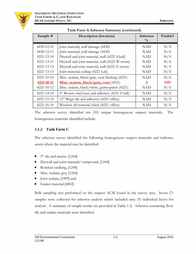
HTM
A12
T
h
1
T
as
B
sa
an
ti
HAZARDOUS MTANK FARMS AMCAS CHERRY
AH Environmen22-89
Sample #
4430-12-10 4430-12-11 4221-13-10 4221-13-11 4221-13-12 4221-13-13
4221-10-10 4221-10-11 4221-10-12
4221-14-10
4221-15-10
4221-16-10
The asbestos
omogenous
.1.2 Tank
The asbestos
ssets where t
9” tile and
Drywall an
Residual c
Misc. seala
Joint seala
Gasket ma
Bulk sampling
amples were
nalysis. A su
le and sealan
MATERIAL INSP
, C, AND RAILH
Y POINT, NC
ntal Consultant
Tan
Joint matJoint matDrywall aDrywall aDrywall aJoint mat
Misc. sealMisc. seaMisc. seal
4” Brown
12” Beige
Window s
s survey ide
materials ide
Farm C
survey iden
the material m
d mastic, [124
nd joint mate
caulking, [124
ant, gray [124
ant, [1899] an
aterial [4802]
g was perfor
collected fo
ummary of sa
nt materials w
ECTION HEAD
ts
nk Farm A A
Descript
erial, wall damerial, wall dam
and joint matand joint matand joint material, ceiling
lant, black/galant, blacklant, black/w
n vinyl base a
e tile and adh
sill material,
entified ten
entified includ
ntified the fo
may be identi
44]
erial/ compo
44]
44]
nd
]
rmed on the
or asbestos a
ample results
were identifie
Asbestos Sum
tion (locatio
mage (4430)mage (4430)terial, wall (42terial, wall (42terial, wall (42(4221 Lab)
gray, vent flas/gray, vent
white, gutter p
and adhesive
hesive (4221 o
black (4221 o
(10) unique
de:
ollowing hom
ified:
ound, [1244]
e suspect AC
analysis whic
s are provide
ed.
1-5
mmary (con
on)
221 S hall) 221 W room221 E room)
shing (4221)(4221)
patch (4221)
(4221 S hall)
office)
office)
e homogeno
mogenous su
CM found in
ch included
ed in Table 1
ntinued)
Asbe%
m) )
NANANANANANA
NA3
NA
) NA
NA
NA
ous suspect
uspect mater
n the survey
nine (9) ind
-2. Asbesto
ASB
Augus
estos %
Fri
AD AD AD AD AD AD
NNNNNN
AD 3 AD
NNN
AD N
AD N
AD N
materials.
rials and ind
y area. Seve
dividual layer
s containing
ESTOS
st 2016
iable?
N/A N/A N/A N/A N/A N/A
N/A NO N/A
N/A
N/A
N/A
The
dicates
en (7)
rs for
floor

HTM
A12
N
A
1
T
as
B
sa
an
se
HAZARDOUS MTANK FARMS AMCAS CHERRY
AH Environmen22-89
Sample #
1244-01-30
1244-03-30
1244-10-30
1244-11-30
1899-10-10 1899-10-11
4802-10-10
Note: record
Appendix C.
.1.3 Railh
The asbestos
ssets where t
Gasket ma
Joint seala
Bulk sampling
amples were
nalysis. A s
ealant was id
MATERIAL INSP
, C, AND RAILH
Y POINT, NC
ntal Consultant
9” Black
Drywall a
Residual c
Misc. sea
Joint sealaJoint seala
Gasket m
data of all m
head Area
survey iden
the material m
aterial, [railhe
ant, [railhead
g was perform
collected for
summary of
entified.
ECTION HEAD
ts
Tank Far
Descript
k tile and mas
and joint mat
caulking, doo
alant, black
ant, beige (Nant, gray (MO
material, acces
materials sam
ntified the fo
may be identi
ead offload,
offload] and
med on the
r asbestos an
sample resu
Table 1-2
rm C Asbest
tion [locatio
stic (head)
terial, ceiling
or (entry)
/gray, wall
N canopy) OGAS Tank)
ss hatch (480
mpled at 1244
ollowing hom
ified:
4651] and
d
suspect ACM
nalysis which
ults are prov
1-6
2
tos Summar
on]
(main room)
(exterior)
k)
02 tank top)
4 during a p
mogenous su
M found in t
included thi
vided in Tab
ry
Asbe%
3/
) NA
NA
4
NANA
NA
prior inspecti
uspect mater
the survey ar
irteen (13) in
ble 1-3. Asb
ASB
Augus
estos %
Fri
/ - N
AD N
AD N
4 N
AD AD
NN
AD N
ion is provid
rials and ind
rea. Thirteen
dividual laye
bestos conta
ESTOS
st 2016
iable?
NO
N/A
N/A
NO
N/A N/A
N/A
ded in
dicates
n (13)
ers for
aining

HTM
A12
1.2
A
D
w
in
in
A
ch
HAZARDOUS MTANK FARMS AMCAS CHERRY
AH Environmen22-89
Sample #
RH-10-10 RH-10-11 RH-10-12 RH-10-13 RH-10-14 RH-10-15 4651-10-10 4651-10-11 4651-10-12
RH-11-10 RH-11-11 RH-11-12 RH-11-13
ACM2
Asbestos cont
Gaske
Roofin
9” Bla
Miscel
Concr
During demol
with those ad
ndicates othe
nspection dra
Additional ins
hain of custo
MATERIAL INSP
, C, AND RAILH
Y POINT, NC
ntal Consultant
Gasket mGasket mGasket mGasket mGasket mGasket mGasket mGasket mGasket m
Joint sealaJoint sealaJoint seaJoint sea
M FINDINGS
taining mater
et material, (T
ng sealant, bl
ack floor tile
llaneous seal
rete joint seal
lition or reno
dressed in th
erwise. Loca
awings (Appe
spection info
ody documen
ECTION HEAD
ts
Railhead
Descript
material, greenmaterial, beigematerial, beigematerial, beigematerial, greenmaterial, beigematerial, gray material, gray material, green
ant, black (Oant, black (O
alant, black alant, black
rials were ide
Tank Farm A
lack/gray (Bu
(Building 12
lant, black/gr
lant, black (R
ovation, any
his report mu
ations of sam
endix A).
ormation is in
nts and buildi
Table 1-3
Area Asbes
tion [locatio
n (OS1) e (OS3) e (OS5) e (OS8) n (OS11) e (OS14) (4651 GTS3(4651 GTS4n (4651 valve
OS1/2) OS5)
(OS11) (OS14)
entified at all
A)
uilding 4221)
44)
ray (Building
Railhead)
building mat
ust be consid
mples and ex
ncluded in th
ing drawings
1-7
3
tos Summar
on]
0) 6) e)
three main a
)
g 1244)
terial that is
dered as an A
xtent of know
he appendices
s
ry
Asbe%
NANANANANANANANANA
NANA
22
areas and inc
not identifie
ACM unless
wn ACM are
s on the lab r
ASB
Augus
estos %
Fri
AD AD AD AD AD AD AD AD AD
NNNNNNNNN
AD AD 2 2
NNNN
clude:
ed as homoge
additional te
e indicated o
reports of an
ESTOS
st 2016
iable?
N/A N/A N/A N/A N/A N/A N/A N/A N/A
N/A N/A NO NO
enous
esting
on the
nalysis

HTM
A12
1.
T
as
M
Su
T
E
SI
Thcosu
HAZARDOUS MTANK FARMS AMCAS CHERRY
AH Environmen22-89
CERT.3
The AIHA a
sbestos cont
Method for t
ubpart F in 4
The inspecto
EPA-approve
IGNATURE O
The above-signed innditions at the tim
uch as wall interio
MATERIAL INSP
, C, AND RAILH
Y POINT, NC
ntal Consultant
TIFICATION
nd NVLAP
tent by PLM
the Determin
40 CFR Part
SAN
r who phys
ed training as
AH1
OF INSPECTOR
nspectors certify infme of survey only. rs may contain ma
ECTION HEAD
ts
Accredited
M and NIOSH
nation of As
763) was:
NAIR TECHN
1551 OA
POW
sically survey
an asbestos
DA
H ENVIRONM
11837 ROCK LNEWP
R:
formation contain Every reasonableaterials not yet ide
laboratory s
H method 7
sbestos in B
NOLOGIES LAKBRIDGE DWHATAN, VA(804) 897-1
yed for ACM
inspector an
AVID W. DO
MENTAL CO
LANDING DPORT NEWS,
(757) 873-49
ed within this asbe attempt was madentified.
1-8
selected to a
7402 method
Bulk Insulatio
LABORATORY
DR, SUITE BA 23139 177
M at the fa
nd manageme
OBSON ONSULTANTS
DRIVE, SUITE
, VA 23608 959
bestos inspection repde to identify all A
analyze the
ds, equivalen
on Samples”
RY, INC.
acility and w
ent planner i
S, INC. E 300
eport is true and cACM. However,
ASB
Augus
bulk sample
nt to the "In
” (Appendix
who has rec
s:
correct concerning s, locations not acce
ESTOS
st 2016
es for
nterim
A to
ceived
site essible

HTM
A12
2
Si
le
C
(P
d
d
p
p
O
an
co
p
re
un
A
(H
id
du
o
st
an
D
at
co
in
if
HAZARDOUS MTANK FARMS AMCAS CHERRY
AH Environmen22-89
2. LEA
ince 1971, th
ead through
CFR 1926.62
PEL) lead of
etermined u
etermined to
aint is requi
ublic, and to
OSHA and E
ny lead base
ontaining lea
rimary testin
enovation or
nnecessary b
A preconstruc
HUD) Title
dentify major
uring renova
f OSHA co
tandards for
nd local regu
Disturbance o
t a minimum
onsidered to
n constructio
f any lead is p
MATERIAL INSP
, C, AND RAILH
Y POINT, NC
ntal Consultant
AD
he constructio
engineering
set the follow
f 50 microgra
using an 8-h
o be a health
ired in order
enact appro
EPA regulatio
ed paint (L
ad (PCL). X
ng method f
r demolition
based on the
ction inspect
X lead insp
r building co
ation/ demol
ompliance.
conducting l
ulations.
of paint conta
m. Above 0
be lead-base
on since OSH
present in the
ECTION HEAD
ts
on industry h
and work p
wing limits fo
ams per cub
hour time w
h threat, ass
r to prevent
opriate contro
ons must be
BP) or pain
X-Ray Fluore
for Tank Fa
. No bulk
XRF finding
ion is not to
pection. Th
omponents c
lition that m
The inspect
lead-based pa
aining lead re
0.5% by we
ed. However
HA standard
e paint; there
2-
has been requ
practice cont
or lead expos
bic meter (µg
weighted ave
sessment of
t occupation
ol measures f
followed wh
nts with det
escence (XRF
arm A, Tank
paint or lead
gs.
be confused
he preconstru
containing le
ay be impact
tion was co
aint activities
equires speci
eight (bulk
r, in the inter
s 29 CFR 19
e is no minim
-1
uired to prot
trols. The c
sure includin
g/m3), and an
erage. Since
buildings fo
nal exposure
for lead haza
hen renovatio
tectable lead
F) testing of
k Farm C,
d wipe samp
d with a Hou
uction inspe
ead in order
ted by the pr
nducted usin
s (40 CFR 74
ial training an
paint) or >1
rest of safety
926.62 (Lead
mum concent
tect workers
current OSH
ng a permissi
n action leve
e lead-based
or the presen
to personn
ards.
on or demol
d levels refe
f component
and Railhea
pling was co
using and Urb
ections prima
to properly
roposed wor
ng the EPA
45.227) as a g
nd initial exp
1.0 mg/cm
y, lower thres
d in Construc
tration level.
SECTIO
Augus
from exposu
HA regulation
ble exposure
el of 30 µg/m
d paint has
nce of lead-b
nel or the ge
lition work a
erred to as
s was used a
ad Areas pri
onducted, de
ban Develop
ary purpose
y address the
rk for the pu
A’s work pr
guide and all
posure monit
m2 (XRF), pa
sholds are ut
ction) are inv
ON 2.0 LEAD
st 2016
ure to
ns 29
e limit
m3, as
been
based
eneral
affects
paint
as the
ior to
eemed
pment
is to
e lead
urpose
actice
l State
toring
aint is
tilized
voked

HTM
A12
T
re
n
A
40
le
Sh
n
o
X
ca
co
2.1
X
T
qu
co
un
ch
L
M
to
co
lo
du
O
im
co
R
HAZARDOUS MTANK FARMS AMCAS CHERRY
AH Environmen22-89
These standa
enovation of
ecessarily lea
An Innov-X,
000, serial nu
ead paint test
heet (PCS) fo
o substrate c
f the testing,
X-ray fluores
alibrations to
omponent.
SAMP1
XRF samplin
This state-of-
uickly determ
oncerning th
nit at the tim
haracteristic
LBP/PCL usi
Most compon
o interpret.
ontain lead.
ocation. Lead
ue to averag
OSHA standa
mpact these
onsidered lea
Results of the
MATERIAL INSP
, C, AND RAILH
Y POINT, NC
ntal Consultant
ards set fort
f painted mat
ad pigment co
X-ray tube
umber 9897)
t mode using
for the instru
corrections w
, and/or ever
scence data
o the NIST
PLING
ng does not
-the-art met
mine if a su
he amount of
me of survey
sheet of th
ing this meth
nents tested a
XRF and bu
The results
d is likely to
ging the weig
ards apply t
paints may
ad-based pain
e lead testing
ECTION HEAD
ts
th the regu
terials or stru
ontaining ite
source, XRF
). The unit w
g the rules an
ument. The X
were required
ry four hour
sheets incl
standard fo
require colle
thod for det
urface conta
f lead contain
using pre an
he equipmen
hod.
are believed
ulk paint ana
only indicate
be present at
ght of other
to any samp
result in exp
nts.
conducted a
ulations that
uctures that c
ms that have
F instrument
was operated
nd procedure
XRF is not s
d. The XRF
s, whichever
luded in A
or XRF sam
ection of ma
termining th
ains LBP/PC
ned in paint.
nd post calib
nt. Areas ar
to contain se
alysis does n
e the amount
t a higher pe
layers of pa
ple with dete
posure to le
are presented
2-2
apply with
contain detec
e been manuf
t was used fo
d by a factor
es found in th
substrate dep
was calibrat
r came first.
Appendix C.
mpling and d
aterial and i
he composit
CL or not,
Data is prov
bration, and b
re immediat
everal layers
not differenti
t of lead that
ercentage in a
aint into the
ectable lead.
ead, even tho
d in the follow
h regards to
ctable amoun
factured.
or this inspe
ry trained use
he Performa
pendent acco
ted prior to u
Calibrations
Quality
duplicate tes
s considered
tion of pain
and provide
vided as reco
by following
tely identified
of paint film
iate which la
t is present i
a particular la
calculation.
Constructi
ough they ar
wing sections
Augus
o constructio
nts of lead an
ection (mode
er in the stan
ance Characte
ording the PC
use and at th
s are noted o
control inc
ting of the
d non-destru
nted surfaces
es sufficient
orded by the
g the perform
d as coated
m and are dif
ayer of paint
in the sample
ayer than rep
For this re
ion activities
re not techn
s.
LEAD
st 2016
on or
nd not
el #a-
ndard
eristic
CS, so
he end
on the
luded
same
uctive.
s can
t data
XRF
mance
with
fficult
t may
e/test
ported
eason,
s that
nically

HTM
A12
2.
A
fo
o
p
le
p
p
w
2.3
L
re
su
fo
T
T
2
C
HAZARDOUS MTANK FARMS AMCAS CHERRY
AH Environmen22-89
XRF 2
An inspection
or the presen
f a represent
resent. Alth
ead” is relev
resented in
rocedures th
were categoriz
Lead-b Conta Conta Detec Readin
LEAD3
Lead inspectio
eadings were
ummary of t
ollowing sect
The building
The complete
.3.1 Lead
Components
Brown Brown Gray a Gray d White White White
MATERIAL INSP
, C, AND RAILH
Y POINT, NC
ntal Consultant
RANGES
n was perform
nce of lead fo
tative numbe
hough OSHA
vant in order
a lead range
hat may be r
zed as follow
based paint [aining elevateaining lead oftable levels ongs below 0.0
COMPONEN
on at the fac
e taken, whi
the compon
tions. A des
or area locat
e XRF sampli
component
tested and de
n vinyl base cn metal gutteand Beige bridrywall wall, e wood trim ae concrete sille block wall, B
ECTION HEAD
ts
med on paint
ound at the p
er of surfaces
A utilizes the
r to determi
e format to a
required dur
ws:
[L] or >1.0 ed lead levels f concern [Cof lead [D] o05 mg/cm2 l
NTS
cility was con
ich included
ents tested a
scription of t
ted and the X
ing summary
ts
etermined to
cove, Buildiner and eave, Bick wall, BuilBuilding 124
and componel, Building 12Building 124
ted and limit
project buildi
s, dependent
term “any d
ine the pote
assist in dete
ring renovati
mg/cm2 lea[E] or betw
C] or betweeor between 0ead were con
nducted 5-7 J
d twenty five
and determin
the compone
XRF reading
y is presented
o be lead-base
ng 4221 [113,Building 4221lding 1244 [044 [008] ents, Building244 [016]
44 [021]
2-3
ted non-pain
ings and asse
t on the quan
detectable lea
ential for lea
ermining pro
ion/ demoli
ad; ween 0.99 anen 0.65 and 00.32 and 0.05nsidered insig
July, 2016.
e (25) test s
ned to cont
ent, including
g numbers ar
d in Appendi
ed [L] or >1
, 115] 1 [118, 119, 1006, 011]
ng 1244 [013,
ted compone
ets. Reading
ntity of the p
ad”, the amou
ad exposure
otective mea
ition activitie
nd 0.66 mg/0.33 mg/cm5 mg/cm2 legnificant.
Two hundre
standards fo
tain lead are
g color and
re also includ
ix C.
1.0 mg/cm2 l
123, 124]
020]
Augus
ents to be su
gs were then
particular ma
unt of “detec
. Informati
asures and sp
es. The rea
/cm2 lead; m2 lead; and
ad.
ed forty-one
or calibration
presented i
substrate is l
ded for refer
lead include:
LEAD
st 2016
uspect
taken
aterial
ctable
ion is
pecial
adings
(241)
n. A
n the
listed.
rence.

HTM
A12
2
C
in
2
C
in
2
C
m
2.4
O
el
o
du
W
p
2
B
HAZARDOUS MTANK FARMS AMCAS CHERRY
AH Environmen22-89
.3.2 Eleva
Components
nclude:
White Gray m
.3.3 Lead
Components
nclude:
White
.3.4 Detec
Components
mg/cm2 lead i
Gray m Yellow Gray m Lt. Gr Red m Unpai White
COMM4
Occupational
levated blood
xidizes and/
usts may cau
Where paints
ose little haz
.4.1 Speci
Based upon th
MATERIAL INSP
, C, AND RAILH
Y POINT, NC
ntal Consultant
ated lead com
tested and d
e wood door, metal valve, T
of concern
tested and d
e window trim
ctable lead c
tested and d
include:
metal supporw metal bollametal framesreen metal st
metal piping, Tinted metal be drywall ceili
MENTS
exposure to
d lead levels.
/or is presen
use lead relate
are intact an
ard. When p
fic recomm
he lead samp
ECTION HEAD
ts
mponents
determined to
Building 124Tank Farm C
component
determined to
m, Building 1
components
determined t
rt frames, Raard, Tank Fars/ beams/ suairway, Tank Tank Farm A
beams, Buildiing, Building
o persons con
Lead paint
nt as lead du
ed health pro
nd firmly adh
paints begin t
endations
pling results, t
o contain ele
44 [012] C [057]
ts
o contain lea
1244 [014]
s
to contain d
ailhead [018, rm A [007] upports, Build
Farm A [074A [076] ing 4803 [087
g 1244 [009]
nducting dist
becomes an
ust. Ingestio
oblems.
hered to the
to deteriorate
the following
2-4
evated lead [E
ad of concer
detectable lea
029, 030]
ding 4416 an4]
7, 088]
turbance or r
n increased ha
on and pote
substrates, d
e, a greater h
g recommend
E] or 0.99- 0
rn [C] or 0.6
ad levels [D
nd 4417 [012,
removal of p
azard when i
entially inhal
deconstructio
hazard exists.
dations are m
Augus
0.66 mg/cm
65 – 0.33 mg
D] or 0.32 –
, 013, 025, 02
paint can res
it deteriorate
ation of resu
on would typ
.
made:
LEAD
st 2016
m2 lead
g/cm2
– 0.05
26]
sult in
es and
ulting
pically

HTM
A12
2
T
o
U
im
to
al
o
A
m
at
w
HAZARDOUS MTANK FARMS AMCAS CHERRY
AH Environmen22-89
Workecompoframin
Removpositivfor de
The leunlike
.4.2 Gener
The followin
perations.
Followaffecti
Inform Any fr
care as
Under no circ
mmediate haz
oxic than ai
lthough chop
perators and
A (TCLP) has
mass of debri
t a reclamatio
waste [EPA 4
MATERIAL INSP
, C, AND RAILH
Y POINT, NC
ntal Consultant
er exposure tonents contang). val of the love impact to ebris disposalead containinely to expose
ral recomm
ng measures
w OSHA anding paints com facility perraming or eqs not to remo
cumstances s
zard as heavy
rborne parti
p saw cutting
d risk of area
s not been c
s for disposa
on facility, th
0 CFR 261.6
ECTION HEAD
ts
testing shouldaining lead ar
ose and flakythe toxicity c
l. ng metal comif manual re
mendations
are recom
d EPA regulantaining lead
rsonnel of thquipment thatove the coati
should torch
y metal vapo
iculates. Th
g also release
contaminatio
conducted on
al has yet to b
he materials
6 (a)(3)(ii)].
d take place dre intact and
y lead paint acharacteristic
mponents at Bemoved and d
mmended to
ations when pd. he inspection t will be reloings.
h cutting of
ors resulting f
he use of n
es particulate
on.
n bulk struct
be determine
are exempt f
2-5
during work factory appli
and debris at c leachate pro
Building 4221dismantled.
conduct o
performing c
n findings. cated/ reuse
metals coate
from the inte
non-torch m
es into the a
tural compon
ed. Note: wh
from regulat
at Building 1ied (ceramic
t Building 124ocedure (TCL
1 are factory
operations s
construction
ed should be
ed with lead
ense heat and
methods are
air posing a r
nents of this
hen scrap me
tion as a pote
Augus
1244 since glazing and m
44 may provLP) test requ
applied and
afely during
operations
handled with
since it pos
d are acutely
always prefe
risk to equip
s project sinc
etal is dispos
entially hazar
LEAD
st 2016
metal
vide a uired
g site
h
ses an
more
ferred,
pment
ce the
sed of
rdous

HTM
A12
2.
T
fo
T
SI
Thth
HAZARDOUS MTANK FARMS AMCAS CHERRY
AH Environmen22-89
CERT5
The AIHA an
or lead and R
The EPA-app
IGNATURE O
The above-signed inhe time of survey on
MATERIAL INSP
, C, AND RAILH
Y POINT, NC
ntal Consultant
TIFICATION
nd NVLAP A
RCRA metals
SAN
proved and tr
AH1
OF INSPECTOR
nspectors certify infnly.
ECTION HEAD
ts
Accredited la
s content, usi
NAIR TECHN
1551 OA
POW
rained inspec
DA
H ENVIRONM
11837 ROCK LNEWP
R:
formation contain
aboratory sele
ing EPA Met
NOLOGIES LAKBRIDGE DWHATAN, VA(804) 897-1
ctor who phy
AVID W. DO
MENTAL CO
LANDING DPORT NEWS,
(757) 873-49
ed within this insp
2-6
ected to anal
thod 6010C w
LABORATORY
DR, SUITE BA 23139 177
ysically survey
OBSON ONSULTANTS
DRIVE, SUITE
, VA 23608 959
pection report is tr
lyze the bulk
was:
RY, INC.
yed the proje
S, INC. E 300
rue and correct con
Augus
k material sam
ect site is
ncerning site condi
LEAD
st 2016
mples
itions at

HTM
A12
3
In
co
se
O
li
b
co
n
3.1
M
st
In
m
ex
M
3
T
li
li
pr
id
HAZARDOUS MTANK FARMS AMCAS CHERRY
AH Environmen22-89
3. OTH
n addition t
oncerns asse
ection.
Older buildin
ighting fixtu
allasts and e
ontain mercu
arrative conc
MERC1
Mercury is a
tate at room
nhalation of
mercury in al
xposure to m
Mercury is us
Fl M Sw Th Th
.1.1 Merc
The use of f
ighting sour
ighting. Ho
roperly man
dentified by
MATERIAL INSP
, C, AND RAILH
Y POINT, NC
ntal Consultant
HER HAZ
to asbestos
essed and p
ng renovatio
ures have po
elemental me
ury switches
cerning the h
CURY
a toxic elem
m temperatur
f mercury v
ll forms is di
mercury prim
sed in a wide
luorescent anMercury vapo
witches and rhermostats ahermometers
ury Lamp I
fluorescent a
rces since th
wever, fluor
naged. Low
looking at th
ECTION HEAD
ts
ZARDS
and lead, v
protocols fol
on creates a
otential to c
ercury in the
s in thermos
hazards of ea
ental metal
es. Human
vapor is ano
istributed vi
marily affects
e variety of c
nd neon lampor and high prelays,
and regulators and manom
Inspection
and high-int
hey can use
rescent and
w mercury f
he metal end
3-
various addi
llowed durin
dditional ite
contain polyc
e fluorescent
stats and oth
ach are discu
with unique
intake of m
other source
a the blood
s the central
common pro
ps, pressure sodi
rs, and meters,
tensity disch
e up to 50
HID lamps
fluorescent
d plates. Lo
-1
itional issue
ng the asses
ems of conc
chlorinated
nt light bulbs
her materials
ussed below
e properties,
mercury is pr
e of human
steam to all
nervous sys
oducts includ
ium lamps,
harge (HID)
percent les
contain me
lamps are c
ow mercury
es are relev
ssment are
cern; specifi
biphenyls (
s. In additio
s of special
w.
, including b
rimarily thro
exposure.
tissues in th
stem and kid
ding:
) lamps is a
ss energy th
ercury and th
currently in
lamps may h
SECTIO
OTHER HAZ
Augus
vant. Addit
described in
ically fluore
(PCB) conta
on, buildings
concern. A
being in a l
ough oral m
Once abso
he body. Ch
dneys.
a wise choic
han incande
herefore mu
use and ca
have “green
ON 3.0 ZARDS
st 2016
tional
n this
escent
aining
s may
brief
liquid
means.
orbed,
hronic
ce for
escent
ust be
an be
” and

HTM
A12
s
bu
am
3
B
sw
if
re
a
3.2
A
O
ca
fi
P
m
P
to
el
ap
p
m
th
P
ca
in
en
HAZARDOUS MTANK FARMS AMCAS CHERRY
AH Environmen22-89
ometimes “g
ulbs. Altho
mount of me
.1.2 Merc
Building may
witches. Wh
f a mercury
enovation or
liquid state,
PCBS2
Another pote
Older fluores
apacitors. In
ixtures were
CBs are re
manufacture o
CBs are syn
o 1977. D
lectrical insu
pplications i
aints, plastic
many other ap
he capacitor)
CBs have b
ancer and a
nclude dama
ndocrine sy
MATERIAL INSP
, C, AND RAILH
Y POINT, NC
ntal Consultant
gold” end ca
ough low me
ercury as sta
ury Switch
y contain o
hen an older
y-filled glass
r demolition
, within a sm
S
ntial concer
scent lightin
nspections in
e present. A
equired to b
or clearly m
nthetic organ
Due to their
ulating prope
including ele
cs and rubb
pplications.
).
been demon
a number of
age to the
ystem. Stud
ECTION HEAD
ts
aps, and are
ercury lamp
andard lamps
Inspection
older style t
r thermostat
s vial is pre
, they are lik
mall glass via
n associated
ng fixtures
ncluded a vi
All ballasts m
be clearly m
marked “NO P
nic chemical
non-flamm
erties, PCBs
ectrical, heat
er products;
A major use
nstrated to c
f serious no
immune sy
dies in hum
typically a s
s (e.g. T5, T
s, they still m
thermostats
is identified
esent. If a
kely to conta
al.
d with buildi
have the p
sual survey
manufacture
marked “NO
PCBs” must
s that were p
mability, chem
s were used i
t transfer, an
; in pigment
e of PCBs w
cause a vari
on-cancer he
ystem, repro
mans provid
3-2
smaller diam
T8) contain
must be hand
that are lik
d, the cover c
any are iden
ain mercury
ing renovatio
potential to
of light fixtu
ed after 1 Ju
O PCBs”.
t be assumed
produced in
mical stabil
in hundreds
nd hydraulic
ts, dyes and
was in fluore
iety of adve
ealth effects
oductive sy
de evidence
meter than or
approximate
dled properly
kely to cont
can be remo
ntified durin
switches. T
ons is the pr
contain ba
ures to deter
uly 1978 tha
Ballasts w
d to contain
the United
lity, high b
of industrial
equipment;
d carbonless
scent light fi
erse health
s in animals
ystem, nervo
for carcino
OTHER HAZ
Augus
riginal T12 (
ely one-tent
y.
tain mercur
oved to deter
ng the cour
The mercury
resence of P
allasts with
rmine if pre-
at do not co
without a da
PCBs.
States from
oiling point
l and comme
as plasticize
s copy paper
fixture ballas
effects inclu
s. These ef
ous system,
ogenic and
ZARDS
st 2016
(1.5”)
th the
ry tilt
rmine
rse of
y is in
PCBs.
PCB
-1980
ontain
ate of
1929
t and
ercial
ers in
r and
sts (in
uding
ffects
, and
non-

HTM
A12
c
1
ot
o
O
3.3
A
id
is
ap
T
un
co
3.4
It
fo
3.5
B
F
fl
T
HAZARDOUS MTANK FARMS AMCAS CHERRY
AH Environmen22-89
carcinogenic
976 to enac
ther things,
f PCBs.
Only electron
UNDE3
A suspected
dentified on
s unknown.
ppears to ind
Testing of the
ndetermined
ollection and
OTHE4
tems of not
ollows:
Exit s
done w
Fire s
damag
RECO5
Broken fluore
ederal Gove
luorescent an
Through recy
MATERIAL INSP
, C, AND RAILH
Y POINT, NC
ntal Consultant
effects of P
ct §6(e) of th
prohibitions
nic style ball
ERGROUND F
undergroun
the Northwe
Although,
dicate soil de
e soils will b
d and the sit
d analysis.
ER ITEMS OF
te for poten
signage may
with caution
strobe lights
ge fire strobe
OMMENDATIO
escent and H
ernment and
nd HID lam
ycling and pr
ECTION HEAD
ts
PCBs. Conc
he Toxic Su
s on the man
asts were ob
FUEL TANK
nd fuel tank,
est exterior o
the tank has
epression ind
be required.
te is paved
F NOTE
ntial regulat
y contain lea
n.
may contai
es and dispo
ONS
HID lamps m
d most local
mps as a univ
roper handli
cern over PC
ubstances Co
nufacture, p
bserved. No
, presumably
of Building 4
s a newer u
dicating dist
However, t
preventing s
tory concern
ad battery b
in mercury h
ose of with fl
must be mana
les have ad
versal waste
ing of spent
3-3
CBs in the e
ontrol Act (
rocessing, a
PCB ballast
y JP5 (as in
4221. The t
upper end pl
turbance of t
the undergro
standard aug
n were note
backup. Rem
high intensi
luorescent li
aged as a haz
dopted dispo
e based upon
lamps as a
environment
TSCA) that
and distribut
ts are believ
ndicated by
tank size and
lumbing fixt
the soils.
ound location
ger bore tec
ed during th
moval if req
ity discharge
ighting.
zardous was
osal regulati
n a “recyclin
universal w
OTHER HAZ
Augus
t led Congre
included am
tion in comm
ved to be pre
y the cover),
d installation
tures and the
n of the tank
chniques and
he inspectio
quired shou
e lamps. D
ste. Howeve
ons for han
ng presumpt
waste, the bur
ZARDS
st 2016
ess in
mong
merce
sent.
, was
n date
e site
k was
d soil
on as
uld be
o not
er, the
ndling
tion”.
rdens

HTM
A12
a
th
A
N
en
d
an
A
co
en
D
d
so
sa
HAZARDOUS MTANK FARMS AMCAS CHERRY
AH Environmen22-89
and liabilitie
heir primary
Although mo
NAVFAC po
nvironmenta
eemed low m
n approved r
All batteries
ollection pr
nvironment.
Determine th
ocumentatio
oils, with or
ample to det
MATERIAL INSP
, C, AND RAILH
Y POINT, NC
ntal Consultant
s placed upo
components
ost light ball
olicy [spec
ally preferred
mercury), H
recycling fac
(lead acid,
otocols/ pro
he installati
on of previou
without petr
termine the m
ECTION HEAD
ts
on disposers
s: spent glas
lasts identifi
ification 02
d manner. T
HID lights, an
cility for disp
lithium, Ni
ogram. Thi
ion date of
us tanks in t
roleum odor
matrix of the
s are reduce
s, aluminum
ied during th
2 82 16.20
Therefore, al
nd all ballas
posal/recycl
iMH, or NiC
is prevents
f the under
the area. Up
rs should be
e soil before
3-4
ed. Recyclin
m, and phosp
he inspectio
0] to dispo
ll fluorescen
sts should be
ling.
Cd) should
hazardous
rground tan
pon excavat
just cause to
further distu
ng facilities
hor and mer
n do not co
ose of all
nt light tubes
e packaged i
be recycled
materials fr
nk and loc
tion, any dar
o stop work
urbance.
OTHER HAZ
Augus
reduce lam
rcury powde
ontain PCBs
ballasts in
s (including
intact and se
d per the fa
rom entering
cate any cl
rk and disco
and collect
ZARDS
st 2016
mps to
er.
, it is
n an
those
ent to
acility
g the
osure
olored
a soil

HTM
A12
HAZARDOUS MTANK FARMS AMCAS CHERRY
AH Environmen22-89
MATERIAL INSP
, C, AND RAILH
Y POINT, NC
ntal Consultant
ECTION HEAD
ts
HAZMA
AT Inspectio
H
on Drawing
HAZMAT INSP
gs
APPEN
PECTION DRAW
Augus
NDIX A WINGS
st 2016

HTM
A12
HAZARDOUS MTANK FARMS AMCAS CHERRY
AH Environmen22-89
MATERIAL INSP
, C, AND RAILH
Y POINT, NC
ntal Consultant
ECTION HEAD
ts
This pagge left blank i
H
intentionally
HAZMAT INSP
y
PECTION DRAW
Augus
WINGS
st 2016


HTM
A12
HAZARDOUS MTANK FARMS AMCAS CHERRY
AH Environmen22-89
MATERIAL INSP
, C, AND RAILH
Y POINT, NC
ntal Consultant
ECTION HEAD
ts
Insp
pection Phooto-Log
INSPE
APPEN
ECTION PHOTO
Augus
NDIX B O-LOG
st 2016

HTM
A12
HAZARDOUS MTANK FARMS AMCAS CHERRY
AH Environmen22-89
MATERIAL INSP
, C, AND RAILH
Y POINT, NC
ntal Consultants
ECTION HEAD
s
This pagge left blank iintentionally
INSPE
y
ECTION PHOTO
Augus
O-LOG
st 2016

Hazardous Material InspectionPOL Tank Farm A, C, and Railhead
MCAS Cherry Point, Havelock NC1 of 2
ACM: Railhead, joint sealant (sample RH-11-12).
ACM: Building 4221, cement panel fume hood known ACM.
ACM: Tank farm A, 4004; gasket material on stainless steel flange (sample 4004-10-10).
ACM: Tank farm A, 4221; sealant on vent flashings (sample 4221-10-11).
ACM: Building 1244, 9” Black floor tile (sample 1244-01-30).
ACM: Building 1244, miscellaneous sealant, gray (sample 1244-11-30).

Hazardous Material InspectionPOL Tank Farm A, C, and Railhead
MCAS Cherry Point, Havelock NC2 of 2
LEAD: Tank Farm C; Elevated lead on OWS valve [XRF057].
OTHER: Building 4221; underground fuel storage, sampling still required.
LEAD: Building 4221; Brown vinyl base cove contains lead [XRF113, 115].
LEAD: Building 4221; Brown metal gutter/ eave contains lead [XRF118, 119, 123, 124].
LEAD: Building 1244; Interior walls and components with lead [XRF006, 008, 011].
LEAD: Building 1244; Interior and exterior wood have lead paint [XRF013, 020].

HTM
A12
HAZARDOUS MTANK FARMS AMCAS CHERRY
AH Environmen22-89
MATERIAL INSP
, C, AND RAILH
Y POINT, NC
ntal Consultant
Labo
ECTION HEAD
ts
oratory, XRF
LABORA
F, and Supp
ATORY, XRF, A
porting Data
AND SUPPORT
a Reports
APPEN
TING DATA REP
Augus
NDIX C PORTS
st 2016

HTM
A12
HAZARDOUS MTANK FARMS AMCAS CHERRY
AH Environmen22-89
MATERIAL INSP
, C, AND RAILH
Y POINT, NC
ntal Consultants
ECTION HEAD
s
This pag
LABORA
ge left blank i
ATORY, XRF, A
intentionally
AND SUPPORT
y
TING DATA REP
Augus
PORTS
st 2016

Page 10 of 12

Page 11 of 12

Page 12 of 12

SanAir Technologies Laboratory, Inc.1551 Oakbridge Drive, Suite B, Powhatan, VA 23139804.897.1177 Toll Free: 888.895.1177 Fax: 804.897.0070Web: http://www.sanair.com E-mail: [email protected]
Name:Address:
AH Environmental Consultants, Inc.11837 Rock Landing DriveSuite 300Newport News, VA 23606
Project Number:P.O. Number:
Project Name:
AH #122-89 ABA
MCAS Cherry Point
Collected Date:Received Date:
Report Date:Analyst:
7/6/20167/13/2016 10:10:00 AM7/19/2016 5:17:07 PMRobertson, ErinRutter, Amber
Asbestos Bulk PLM EPA 600/R-93/116Stereoscopic Components Asbestos
SanAir ID / Description Appearance % Fibrous % Non-Fibrous Fibers4004-10-10 / 16024089-001 Grey 40% Other 60% Chrysotile
Non-FibrousHomogeneous
Stereoscopic Components AsbestosSanAir ID / Description Appearance % Fibrous % Non-Fibrous Fibers4004-10-11 / 16024089-002 Green 60% Cellulose 40% Other None Detected
FibrousHomogeneous
Stereoscopic Components AsbestosSanAir ID / Description Appearance % Fibrous % Non-Fibrous Fibers4004-10-12 / 16024089-003 Brown 10% Cellulose 88% Other None Detected
Non-Fibrous 2% GlassHeterogeneous
Stereoscopic Components AsbestosSanAir ID / Description Appearance % Fibrous % Non-Fibrous Fibers4416-10-10 / 16024089-004 Green 60% Cellulose 30% Other None Detected
Fibrous 10% WollastoniteHomogeneous
Stereoscopic Components AsbestosSanAir ID / Description Appearance % Fibrous % Non-Fibrous Fibers4417-10-10 / 16024089-005 Green 60% Cellulose 30% Other None Detected
Fibrous 10% WollastoniteHomogeneous
Stereoscopic Components AsbestosSanAir ID / Description Appearance % Fibrous % Non-Fibrous Fibers4430-10-10 / 16024089-006 Black 15% Glass 85% Other None DetectedShingle Non-Fibrous
Homogeneous
4430-10-10 / 16024089-006 Black 60% Cellulose 40% Other None DetectedTar Paper Non-Fibrous
Homogeneous
16024089SanAir ID Number
FINAL REPORT
Certification
Analyst: Approved Signatory:
Analysis Date: 7/19/2016 Date: 7/19/2016 Page 3 of 12

SanAir Technologies Laboratory, Inc.1551 Oakbridge Drive, Suite B, Powhatan, VA 23139804.897.1177 Toll Free: 888.895.1177 Fax: 804.897.0070Web: http://www.sanair.com E-mail: [email protected]
Name:Address:
AH Environmental Consultants, Inc.11837 Rock Landing DriveSuite 300Newport News, VA 23606
Project Number:P.O. Number:
Project Name:
AH #122-89 ABA
MCAS Cherry Point
Collected Date:Received Date:
Report Date:Analyst:
7/6/20167/13/2016 10:10:00 AM7/19/2016 5:17:07 PMRobertson, ErinRutter, Amber
Asbestos Bulk PLM EPA 600/R-93/116Stereoscopic Components Asbestos
SanAir ID / Description Appearance % Fibrous % Non-Fibrous Fibers4430-10-11 / 16024089-007 Black 15% Glass 85% Other None DetectedShingle Non-Fibrous
Homogeneous
4430-10-11 / 16024089-007 Black 60% Cellulose 40% Other None DetectedTar Paper Non-Fibrous
Homogeneous
Stereoscopic Components AsbestosSanAir ID / Description Appearance % Fibrous % Non-Fibrous Fibers4430-11-10 / 16024089-008 White 100% Other None Detected
Non-FibrousHomogeneous
Stereoscopic Components AsbestosSanAir ID / Description Appearance % Fibrous % Non-Fibrous Fibers4002-11-10 / 16024089-009 Black 5% Cellulose 95% Other None Detected
Non-FibrousHomogeneous
Stereoscopic Components AsbestosSanAir ID / Description Appearance % Fibrous % Non-Fibrous Fibers4002-10-10 / 16024089-010 Green 60% Cellulose 30% Other None Detected
Fibrous 10% WollastoniteHomogeneous
Stereoscopic Components AsbestosSanAir ID / Description Appearance % Fibrous % Non-Fibrous Fibers4001-10-11 / 16024089-011 Black 5% Cellulose 95% Other None Detected
Non-FibrousHomogeneous
Stereoscopic Components AsbestosSanAir ID / Description Appearance % Fibrous % Non-Fibrous Fibers4636-10-10 / 16024089-012 Off-White 2% Cellulose 98% Other None Detected
Non-FibrousHomogeneous
16024089SanAir ID Number
FINAL REPORT
Certification
Analyst: Approved Signatory:
Analysis Date: 7/19/2016 Date: 7/19/2016 Page 4 of 12

SanAir Technologies Laboratory, Inc.1551 Oakbridge Drive, Suite B, Powhatan, VA 23139804.897.1177 Toll Free: 888.895.1177 Fax: 804.897.0070Web: http://www.sanair.com E-mail: [email protected]
Name:Address:
AH Environmental Consultants, Inc.11837 Rock Landing DriveSuite 300Newport News, VA 23606
Project Number:P.O. Number:
Project Name:
AH #122-89 ABA
MCAS Cherry Point
Collected Date:Received Date:
Report Date:Analyst:
7/6/20167/13/2016 10:10:00 AM7/19/2016 5:17:07 PMRobertson, ErinRutter, Amber
Asbestos Bulk PLM EPA 600/R-93/116Stereoscopic Components Asbestos
SanAir ID / Description Appearance % Fibrous % Non-Fibrous Fibers4803-10-10 / 16024089-013 Beige 60% Cellulose 40% Other None Detected
FibrousHomogeneous
Stereoscopic Components AsbestosSanAir ID / Description Appearance % Fibrous % Non-Fibrous Fibers4803-10-11 / 16024089-014 Beige 60% Cellulose 40% Other None Detected
FibrousHomogeneous
Stereoscopic Components AsbestosSanAir ID / Description Appearance % Fibrous % Non-Fibrous Fibers4803-10-12 / 16024089-015 Beige 60% Cellulose 40% Other None Detected
FibrousHomogeneous
Stereoscopic Components AsbestosSanAir ID / Description Appearance % Fibrous % Non-Fibrous Fibers4803-10-13 / 16024089-016 Green 60% Cellulose 30% Other None Detected
Fibrous 10% WollastoniteHomogeneous
Stereoscopic Components AsbestosSanAir ID / Description Appearance % Fibrous % Non-Fibrous Fibers4430-12-10 / 16024089-017 White 100% Other None Detected
Non-FibrousHomogeneous
Stereoscopic Components AsbestosSanAir ID / Description Appearance % Fibrous % Non-Fibrous Fibers4430-12-11 / 16024089-018 White 100% Other None Detected
Non-FibrousHomogeneous
16024089SanAir ID Number
FINAL REPORT
Certification
Analyst: Approved Signatory:
Analysis Date: 7/19/2016 Date: 7/19/2016 Page 5 of 12

SanAir Technologies Laboratory, Inc.1551 Oakbridge Drive, Suite B, Powhatan, VA 23139804.897.1177 Toll Free: 888.895.1177 Fax: 804.897.0070Web: http://www.sanair.com E-mail: [email protected]
Name:Address:
AH Environmental Consultants, Inc.11837 Rock Landing DriveSuite 300Newport News, VA 23606
Project Number:P.O. Number:
Project Name:
AH #122-89 ABA
MCAS Cherry Point
Collected Date:Received Date:
Report Date:Analyst:
7/6/20167/13/2016 10:10:00 AM7/19/2016 5:17:07 PMRobertson, ErinRutter, Amber
Asbestos Bulk PLM EPA 600/R-93/116Stereoscopic Components Asbestos
SanAir ID / Description Appearance % Fibrous % Non-Fibrous Fibers4221-10-10 / 16024089-019 Black 4% Cellulose 96% Other None Detected
Non-FibrousHomogeneous
Stereoscopic Components AsbestosSanAir ID / Description Appearance % Fibrous % Non-Fibrous Fibers4221-10-11 / 16024089-020 Black 2% Cellulose 95% Other 3% Chrysotile
Non-FibrousHomogeneous
Stereoscopic Components AsbestosSanAir ID / Description Appearance % Fibrous % Non-Fibrous Fibers4221-11-10 / 16024089-021 Black 15% Glass 85% Other None DetectedShingle Non-Fibrous
Homogeneous
4221-11-10 / 16024089-021 Black 60% Cellulose 40% Other None DetectedTar Paper Non-Fibrous
Homogeneous
Stereoscopic Components AsbestosSanAir ID / Description Appearance % Fibrous % Non-Fibrous Fibers4221-10-12 / 16024089-022 Black 20% Synthetic 80% Other None Detected
Non-FibrousHomogeneous
Stereoscopic Components AsbestosSanAir ID / Description Appearance % Fibrous % Non-Fibrous Fibers4221-13-10 / 16024089-023 White 3% Glass 97% Other None DetectedDrywall Non-Fibrous
Homogeneous
4221-13-10 / 16024089-023 White 100% Other None DetectedJoint Compound Non-Fibrous
Homogeneous
16024089SanAir ID Number
FINAL REPORT
Certification
Analyst: Approved Signatory:
Analysis Date: 7/19/2016 Date: 7/19/2016 Page 6 of 12

SanAir Technologies Laboratory, Inc.1551 Oakbridge Drive, Suite B, Powhatan, VA 23139804.897.1177 Toll Free: 888.895.1177 Fax: 804.897.0070Web: http://www.sanair.com E-mail: [email protected]
Name:Address:
AH Environmental Consultants, Inc.11837 Rock Landing DriveSuite 300Newport News, VA 23606
Project Number:P.O. Number:
Project Name:
AH #122-89 ABA
MCAS Cherry Point
Collected Date:Received Date:
Report Date:Analyst:
7/6/20167/13/2016 10:10:00 AM7/19/2016 5:17:07 PMRobertson, ErinRutter, Amber
Asbestos Bulk PLM EPA 600/R-93/116Stereoscopic Components Asbestos
SanAir ID / Description Appearance % Fibrous % Non-Fibrous Fibers4221-13-11 / 16024089-024 White 5% Glass 95% Other None DetectedDrywall Non-Fibrous
Homogeneous
4221-13-11 / 16024089-024 White 100% Other None DetectedJoint Compound Non-Fibrous
Homogeneous
Stereoscopic Components AsbestosSanAir ID / Description Appearance % Fibrous % Non-Fibrous Fibers4221-13-12 / 16024089-025 White 3% Glass 97% Other None DetectedDrywall Non-Fibrous
Homogeneous
4221-13-12 / 16024089-025 White 100% Other None DetectedJoint Compound Non-Fibrous
Homogeneous
Stereoscopic Components AsbestosSanAir ID / Description Appearance % Fibrous % Non-Fibrous Fibers4221-13-13 / 16024089-026 White 100% Other None Detected
Non-FibrousHomogeneous
Stereoscopic Components AsbestosSanAir ID / Description Appearance % Fibrous % Non-Fibrous Fibers4221-14-10 / 16024089-027 Brown 100% Other None DetectedVinyl Base Non-Fibrous
Homogeneous
4221-14-10 / 16024089-027 Yellow 100% Other None DetectedAdhesive Non-Fibrous
Homogeneous
Stereoscopic Components AsbestosSanAir ID / Description Appearance % Fibrous % Non-Fibrous Fibers4221-15-10 / 16024089-028 Beige 100% Other None DetectedFloor Tile Non-Fibrous
Homogeneous
4221-15-10 / 16024089-028 Yellow 100% Other None DetectedMastic Non-Fibrous
Homogeneous
16024089SanAir ID Number
FINAL REPORT
Certification
Analyst: Approved Signatory:
Analysis Date: 7/19/2016 Date: 7/19/2016 Page 7 of 12

SanAir Technologies Laboratory, Inc.1551 Oakbridge Drive, Suite B, Powhatan, VA 23139804.897.1177 Toll Free: 888.895.1177 Fax: 804.897.0070Web: http://www.sanair.com E-mail: [email protected]
Name:Address:
AH Environmental Consultants, Inc.11837 Rock Landing DriveSuite 300Newport News, VA 23606
Project Number:P.O. Number:
Project Name:
AH #122-89 ABA
MCAS Cherry Point
Collected Date:Received Date:
Report Date:Analyst:
7/6/20167/13/2016 10:10:00 AM7/19/2016 5:17:07 PMRobertson, ErinRutter, Amber
Asbestos Bulk PLM EPA 600/R-93/116Stereoscopic Components Asbestos
SanAir ID / Description Appearance % Fibrous % Non-Fibrous Fibers4221-16-10 / 16024089-029 Black 100% Other None Detected
Non-FibrousHomogeneous
16024089SanAir ID Number
FINAL REPORT
Certification
Analyst: Approved Signatory:
Analysis Date: 7/19/2016 Date: 7/19/2016 Page 8 of 12

Page 6 of 6

SanAir Technologies Laboratory, Inc.1551 Oakbridge Drive, Suite B, Powhatan, VA 23139804.897.1177 Toll Free: 888.895.1177 Fax: 804.897.0070Web: http://www.sanair.com E-mail: [email protected]
Name:Address:
AH Environmental Consultants, Inc.11837 Rock Landing DriveSuite 300Newport News, VA 23606
Project Number:P.O. Number:
Project Name:
AH #122-89 ABA
MCAS Cherry Point 1244, 1899, 4802 (C Farm)
Collected Date:Received Date:
Report Date:Analyst:
7/5/20167/13/2016 10:10:00 AM7/19/2016 3:43:43 PMToth, Elizabeth
Asbestos Bulk PLM EPA 600/R-93/116Stereoscopic Components Asbestos
SanAir ID / Description Appearance % Fibrous % Non-Fibrous Fibers1244-01-30 / 16024094-001 Black 97% Other 3% ChrysotileTile Non-Fibrous
Homogeneous
1244-01-30 / 16024094-001 Black 100% Other None DetectedMastic Non-Fibrous
Homogeneous
Stereoscopic Components AsbestosSanAir ID / Description Appearance % Fibrous % Non-Fibrous Fibers1244-03-30 / 16024094-002 Off-White 5% Cellulose 95% Other None DetectedDrywall Non-Fibrous
Homogeneous
1244-03-30 / 16024094-002 White 100% Other None DetectedJoint Material Non-Fibrous
Homogeneous
Stereoscopic Components AsbestosSanAir ID / Description Appearance % Fibrous % Non-Fibrous Fibers1244-10-30 / 16024094-003 White 100% Other None Detected
Non-FibrousHomogeneous
Stereoscopic Components AsbestosSanAir ID / Description Appearance % Fibrous % Non-Fibrous Fibers1244-11-30 / 16024094-004 Grey 96% Other 4% Chrysotile
Non-FibrousHomogeneous
Stereoscopic Components AsbestosSanAir ID / Description Appearance % Fibrous % Non-Fibrous Fibers1899-10-10 / 16024094-005 Beige 100% Other None Detected
Non-FibrousHomogeneous
Stereoscopic Components AsbestosSanAir ID / Description Appearance % Fibrous % Non-Fibrous Fibers1899-10-11 / 16024094-006 Grey 100% Other None Detected
Non-FibrousHomogeneous
16024094SanAir ID Number
FINAL REPORT
Certification
Analyst: Approved Signatory:
Analysis Date: 7/19/2016 Date: 7/19/2016 Page 3 of 6

SanAir Technologies Laboratory, Inc.1551 Oakbridge Drive, Suite B, Powhatan, VA 23139804.897.1177 Toll Free: 888.895.1177 Fax: 804.897.0070Web: http://www.sanair.com E-mail: [email protected]
Name:Address:
AH Environmental Consultants, Inc.11837 Rock Landing DriveSuite 300Newport News, VA 23606
Project Number:P.O. Number:
Project Name:
AH #122-89 ABA
MCAS Cherry Point 1244, 1899, 4802 (C Farm)
Collected Date:Received Date:
Report Date:Analyst:
7/5/20167/13/2016 10:10:00 AM7/19/2016 3:43:43 PMToth, Elizabeth
Asbestos Bulk PLM EPA 600/R-93/116Stereoscopic Components Asbestos
SanAir ID / Description Appearance % Fibrous % Non-Fibrous Fibers4802-10-10 / 16024094-007 Black 10% Cellulose 87% Other None Detected
Non-Fibrous 3% GlassHomogeneous
16024094SanAir ID Number
FINAL REPORT
Certification
Analyst: Approved Signatory:
Analysis Date: 7/19/2016 Date: 7/19/2016 Page 4 of 6

Page 6 of 6

SanAir Technologies Laboratory, Inc.1551 Oakbridge Drive, Suite B, Powhatan, VA 23139804.897.1177 Toll Free: 888.895.1177 Fax: 804.897.0070Web: http://www.sanair.com E-mail: [email protected]
Name:Address:
AH Environmental Consultants, Inc.11837 Rock Landing DriveSuite 300Newport News, VA 23606
Project Number:P.O. Number:
Project Name:
AH #122-89 ABA
MCAS Cherry Point Truck Offload, 4651 Railhead
Collected Date:Received Date:
Report Date:Analyst:
7/13/20167/13/2016 10:10:00 AM7/19/2016 5:15:12 PMChildress, Susan
Asbestos Bulk PLM EPA 600/R-93/116Stereoscopic Components Asbestos
SanAir ID / Description Appearance % Fibrous % Non-Fibrous FibersRH-10-10 / 16024092-001 Green 30% Cellulose 70% Other None Detected
Non-FibrousHomogeneous
Stereoscopic Components AsbestosSanAir ID / Description Appearance % Fibrous % Non-Fibrous FibersRH-11-10 / 16024092-002 Black 100% Other None Detected
Non-FibrousHomogeneous
Stereoscopic Components AsbestosSanAir ID / Description Appearance % Fibrous % Non-Fibrous FibersRH-10-11 / 16024092-003 Beige 90% Cellulose 10% Other None Detected
FibrousHomogeneous
Stereoscopic Components AsbestosSanAir ID / Description Appearance % Fibrous % Non-Fibrous FibersRH-11-11 / 16024092-004 Black 100% Other None Detected
Non-FibrousHomogeneous
Stereoscopic Components AsbestosSanAir ID / Description Appearance % Fibrous % Non-Fibrous FibersRH-10-12 / 16024092-005 Beige 90% Cellulose 10% Other None Detected
FibrousHomogeneous
Stereoscopic Components AsbestosSanAir ID / Description Appearance % Fibrous % Non-Fibrous FibersRH-10-13 / 16024092-006 Beige 90% Cellulose 10% Other None Detected
FibrousHomogeneous
Stereoscopic Components AsbestosSanAir ID / Description Appearance % Fibrous % Non-Fibrous FibersRH-10-14 / 16024092-007 Green 30% Cellulose 70% Other None Detected
Non-FibrousHomogeneous
16024092SanAir ID Number
FINAL REPORT
Certification
Analyst: Approved Signatory:
Analysis Date: 7/19/2016 Date: 7/19/2016 Page 3 of 6

SanAir Technologies Laboratory, Inc.1551 Oakbridge Drive, Suite B, Powhatan, VA 23139804.897.1177 Toll Free: 888.895.1177 Fax: 804.897.0070Web: http://www.sanair.com E-mail: [email protected]
Name:Address:
AH Environmental Consultants, Inc.11837 Rock Landing DriveSuite 300Newport News, VA 23606
Project Number:P.O. Number:
Project Name:
AH #122-89 ABA
MCAS Cherry Point Truck Offload, 4651 Railhead
Collected Date:Received Date:
Report Date:Analyst:
7/13/20167/13/2016 10:10:00 AM7/19/2016 5:15:12 PMChildress, Susan
Asbestos Bulk PLM EPA 600/R-93/116Stereoscopic Components Asbestos
SanAir ID / Description Appearance % Fibrous % Non-Fibrous FibersRH-11-12 / 16024092-008 Black 98% Other 2% Chrysotile
Non-FibrousHomogeneous
Stereoscopic Components AsbestosSanAir ID / Description Appearance % Fibrous % Non-Fibrous FibersRH-10-15 / 16024092-009 Beige 90% Cellulose 10% Other None Detected
FibrousHomogeneous
Stereoscopic Components AsbestosSanAir ID / Description Appearance % Fibrous % Non-Fibrous FibersRH-11-13 / 16024092-010 Black 98% Other 2% Chrysotile
Non-FibrousHomogeneous
Stereoscopic Components AsbestosSanAir ID / Description Appearance % Fibrous % Non-Fibrous Fibers4651-10-10 / 16024092-011 Grey 20% Cellulose 80% Other None Detected
Non-FibrousHomogeneous
Stereoscopic Components AsbestosSanAir ID / Description Appearance % Fibrous % Non-Fibrous Fibers4651-10-11 / 16024092-012 Grey 20% Cellulose 80% Other None Detected
Non-FibrousHomogeneous
Stereoscopic Components AsbestosSanAir ID / Description Appearance % Fibrous % Non-Fibrous Fibers4651-10-12 / 16024092-013 Green 30% Cellulose 70% Other None Detected
Non-FibrousHomogeneous
16024092SanAir ID Number
FINAL REPORT
Certification
Analyst: Approved Signatory:
Analysis Date: 7/19/2016 Date: 7/19/2016 Page 4 of 6

MCAS Cherry Point
Fuel System Upgrades
XRF Readings
ReadingPb
Pb +/‐LL
COMPO
NEN
TCO
LOR
SUBSTRATE
CONDITIO
NLO
CATION
NOTE
Date
21.14
0.06X
STANDARD
REDGOOD
Railhead7‐Jul‐16
31.04
0.04X
STANDARD
REDGOOD
Railhead7‐Jul‐16
41.08
0.04X
STANDARD
REDGOOD
Railhead7‐Jul‐16
50.00
0.00MISCELLAN
EOUS
WHITE
METAL
GOOD
FILL 14piping
7‐Jul‐16
60.00
0.00MISCELLAN
EOUS
BLUE
METAL
GOOD
FILL 14piping
7‐Jul‐16
70.00
0.00MISCELLAN
EOUS
BLUE
METAL
GOOD
FILL 13piping
7‐Jul‐16
80.00
0.00MISCELLAN
EOUS
WHITE
METAL
GOOD
FILL 13piping
7‐Jul‐16
90.00
0.00MISCELLAN
EOUS
YELLOW
METAL
GOOD
FILL 13bollard
7‐Jul‐16
100.00
0.00MISCELLAN
EOUS
BLUE
METAL
GOOD
FILL 11piping
7‐Jul‐16
110.00
0.00MISCELLAN
EOUS
WHITE
METAL
GOOD
FILL 11piping
7‐Jul‐16
120.00
0.00MISCELLAN
EOUS
BLUE
METAL
GOOD
FILL 11handle
7‐Jul‐16
130.00
0.00MISCELLAN
EOUS
WHITE
METAL
GOOD
FILL 8piping
7‐Jul‐16
140.00
0.00MISCELLAN
EOUS
BLUE
METAL
GOOD
FILL 8piping
7‐Jul‐16
150.00
0.00MISCELLAN
EOUS
YELLOW
METAL
GOOD
FILL 8bollards
7‐Jul‐16
160.00
0.00MISCELLAN
EOUS
WHITE
METAL
GOOD
FILL 7piping
7‐Jul‐16
170.00
0.00MISCELLAN
EOUS
WHITE
METAL
GOOD
FILL 6piping
7‐Jul‐16
180.20
0.06D
MISCELLAN
EOUS
GRAY
METAL
GOOD
FILL 6support
7‐Jul‐16
190.00
0.00MISCELLAN
EOUS
WHITE
METAL
GOOD
FILL 6piping
7‐Jul‐16
200.00
0.00MISCELLAN
EOUS
WHITE
METAL
GOOD
FILL 5piping
7‐Jul‐16
210.00
0.00MISCELLAN
EOUS
BLUE
METAL
GOOD
FILL 5piping
7‐Jul‐16
220.00
0.00MISCELLAN
EOUS
BLUE
METAL
GOOD
FILL 4piping
7‐Jul‐16
230.00
0.00MISCELLAN
EOUS
WHITE
METAL
GOOD
FILL 2piping
7‐Jul‐16
240.00
0.00MISCELLAN
EOUS
WHITE
METAL
GOOD
FILL 2piping
7‐Jul‐16
250.00
0.00MISCELLAN
EOUS
BLUE
METAL
GOOD
FILL 2piping
7‐Jul‐16
260.00
0.00MISCELLAN
EOUS
YELLOW
METAL
GOOD
FILL 2bollards
7‐Jul‐16
270.00
0.00MISCELLAN
EOUS
WHITE
METAL
GOOD
FILL 1piping
7‐Jul‐16
280.00
0.00MISCELLAN
EOUS
BLUE
METAL
GOOD
FILL 1valve
7‐Jul‐16
290.16
0.05D
MISCELLAN
EOUS
GRAY
METAL
GOOD
FILL 1support
7‐Jul‐16
300.14
0.04D
MISCELLAN
EOUS
GRAY
METAL
GOOD
FILL 7support
7‐Jul‐16
310.00
0.00MISCELLAN
EOUS
WHITE
METAL
GOOD
main
vent7‐Jul‐16
320.00
0.00MISCELLAN
EOUS
WHITE
METAL
GOOD
main
vent7‐Jul‐16
330.00
0.00MISCELLAN
EOUS
WHITE
METAL
GOOD
4651piping
7‐Jul‐16
340.00
0.00MISCELLAN
EOUS
WHITE
METAL
GOOD
4651piping
7‐Jul‐16
AH Environm
ental Consultants, Inc.D Dobson
Lead Paint M
ode

MCAS Cherry Point
Fuel System Upgrades
XRF Readings
ReadingPb
Pb +/‐LL
COMPO
NEN
TCO
LOR
SUBSTRATE
CONDITIO
NLO
CATION
NOTE
Date
350.00
0.00MISCELLAN
EOUS
WHITE
METAL
GOOD
4651filter
7‐Jul‐16
360.00
0.00MISCELLAN
EOUS
WHITE
METAL
GOOD
4651tank
7‐Jul‐16
370.00
0.00MISCELLAN
EOUS
WHITE
METAL
GOOD
4651piping
7‐Jul‐16
380.00
0.00MISCELLAN
EOUS
WHITE
METAL
GOOD
4651piping
7‐Jul‐16
390.00
0.00MISCELLAN
EOUS
WHITE
METAL
GOOD
4651valve
7‐Jul‐16
400.00
0.00MISCELLAN
EOUS
WHITE
METAL
GOOD
4651piping
7‐Jul‐16
410.00
0.00MISCELLAN
EOUS
WHITE
METAL
GOOD
4651filter
7‐Jul‐16
420.00
0.00MISCELLAN
EOUS
WHITE
METAL
GOOD
4651piping
7‐Jul‐16
430.00
0.00MISCELLAN
EOUS
WHITE
METAL
GOOD
4651piping
7‐Jul‐16
440.00
0.00MISCELLAN
EOUS
WHITE
METAL
GOOD
4651valve
7‐Jul‐16
450.00
0.00MISCELLAN
EOUS
GREEN
METAL
GOOD
4651motor
7‐Jul‐16
460.00
0.00MISCELLAN
EOUS
WHITE
METAL
GOOD
4651piping
7‐Jul‐16
470.00
0.00MISCELLAN
EOUS
WHITE
METAL
GOOD
4651piping
7‐Jul‐16
480.00
0.00MISCELLAN
EOUS
WHITE
METAL
GOOD
4651piping
7‐Jul‐16
490.00
0.00MISCELLAN
EOUS
WHITE
METAL
GOOD
4651fram
ework
7‐Jul‐16
500.00
0.00MISCELLAN
EOUS
WHITE
METAL
GOOD
4651valve
7‐Jul‐16
510.00
0.00FIRE EXTIN
GUISHER
REDMETAL
GOOD
46517‐Jul‐16
521.14
0.06X
STANDARD
REDGOOD
Railheadend
cal7‐Jul‐16
531.16
0.07X
STANDARD
REDGOOD
Railheadend
cal7‐Jul‐16
541.07
0.04X
STANDARD
REDGOOD
Railheadend
cal7‐Jul‐16
21.05
0.04X
STANDARD
REDGOOD
A farm
6‐Jul‐16
31.05
0.03X
STANDARD
REDGOOD
A farm
6‐Jul‐16
41.10
0.04X
STANDARD
REDGOOD
A farm
6‐Jul‐16
50.00
0.00STAN
DARDWHITE
GOOD
A farm
blank6‐Jul‐16
60.01
0.00MISCELLAN
EOUS
METAL
GOOD
A farm
40046‐Jul‐16
70.05
0.03D
MISCELLAN
EOUS
YELLOW
METAL
GOOD
4004bollard
6‐Jul‐16
80.03
0.02MISCELLAN
EOUS
YELLOW
METAL
GOOD
4004bollard
6‐Jul‐16
90.00
0.00MISCELLAN
EOUS
YELLOW
METAL
GOOD
4004filter
6‐Jul‐16
100.01
0.00MISCELLAN
EOUS
METAL
GOOD
4004beam
6‐Jul‐16
110.00
0.00MISCELLAN
EOUS
GRAY
METAL
GOOD
4004toof
6‐Jul‐16
120.31
0.09D
MISCELLAN
EOUS
GRAY
METAL
GOOD
44166‐Jul‐16
130.21
0.08D
MISCELLAN
EOUS
GRAY
METAL
GOOD
4416beam
s6‐Jul‐16
140.00
0.01MISCELLAN
EOUS
YELLOW
METAL
GOOD
4416bollard
6‐Jul‐16
AH Environm
ental Consultants, Inc.D Dobson
Lead Paint M
ode

MCAS Cherry Point
Fuel System Upgrades
XRF Readings
ReadingPb
Pb +/‐LL
COMPO
NEN
TCO
LOR
SUBSTRATE
CONDITIO
NLO
CATION
NOTE
Date
150.00
0.00MISCELLAN
EOUS
YELLOW
CONCRETE
GOOD
4416base
footing6‐Jul‐16
160.00
0.00MISCELLAN
EOUS
YELLOW
CONCRETE
GOOD
4416curb
6‐Jul‐16
170.00
0.00MISCELLAN
EOUS
YELLOW
METAL
GOOD
4416filter
6‐Jul‐16
180.00
0.00MISCELLAN
EOUS
WHITE
METAL
GOOD
4416piping
6‐Jul‐16
190.00
0.00MISCELLAN
EOUS
BLUE
METAL
GOOD
4416piping
6‐Jul‐16
200.00
0.00MISCELLAN
EOUS
WHITE
METAL
GOOD
4416piping
6‐Jul‐16
210.00
0.00MISCELLAN
EOUS
YELLOW
METAL
GOOD
4416filter
6‐Jul‐16
220.00
0.00MISCELLAN
EOUS
REDMETAL
GOOD
44166‐Jul‐16
230.00
0.01MISCELLAN
EOUS
YELLOW
METAL
GOOD
4416bollard
6‐Jul‐16
240.00
0.00MISCELLAN
EOUS
YELLOW
METAL
GOOD
4417curb
6‐Jul‐16
250.27
0.09D
MISCELLAN
EOUS
METAL
GOOD
4417beam
6‐Jul‐16
260.18
0.07D
MISCELLAN
EOUS
METAL
GOOD
4417beam
6‐Jul‐16
270.00
0.00MISCELLAN
EOUS
GRAY
METAL
GOOD
4417room
6‐Jul‐16
280.00
0.00MISCELLAN
EOUS
WHITE
METAL
GOOD
4417gutter
6‐Jul‐16
290.00
0.00MISCELLAN
EOUS
YELLOW
METAL
GOOD
4417base
6‐Jul‐16
300.00
0.00MISCELLAN
EOUS
WHITE
WOOD
GOOD
4430facia
6‐Jul‐16
310.00
0.00MISCELLAN
EOUS
WHITE
WOOD
GOOD
4430facia trim
6‐Jul‐16
320.00
0.00MISCELLAN
EOUS
WHITE
WOOD
GOOD
4430facia eave
6‐Jul‐16
330.00
0.00MISCELLAN
EOUS
WHITE
WOOD
GOOD
4430facia
6‐Jul‐16
340.00
0.00MISCELLAN
EOUS
WHITE
WOOD
GOOD
4430facia trim
6‐Jul‐16
350.00
0.00MISCELLAN
EOUS
WHITE
WOOD
GOOD
4430facia eave
6‐Jul‐16
360.00
0.00WALL
WHITE
METAL
GOOD
4430aw
ning6‐Jul‐16
370.00
0.00MISCELLAN
EOUS
WHITE
METAL
GOOD
4430eave
6‐Jul‐16
380.00
0.00WALL
GRAY
BLOCK
GOOD
44306‐Jul‐16
390.00
0.00MISCELLAN
EOUS
GRAY
WOOD
GOOD
44306‐Jul‐16
400.00
0.00CEILIN
GWHITE
DRYWALL
GOOD
44306‐Jul‐16
410.00
0.00CEILIN
GWHITE
DRYWALL
GOOD
44306‐Jul‐16
420.00
0.00WALL
BEIGE
DRYWALL
GOOD
44306‐Jul‐16
430.00
0.00WALL
BEIGE
DRYWALL
GOOD
44306‐Jul‐16
440.00
0.00WALL
BEIGE
DRYWALL
GOOD
44306‐Jul‐16
450.00
0.00DO
OR TRIM
GRAY
WOOD
GOOD
44306‐Jul‐16
460.00
0.00BASE CO
VEBLACK
VINYL
GOOD
44306‐Jul‐16
470.00
0.00MISCELLAN
EOUS
WHITE
METAL
GOOD
40026‐Jul‐16
AH Environm
ental Consultants, Inc.D Dobson
Lead Paint M
ode

MCAS Cherry Point
Fuel System Upgrades
XRF Readings
ReadingPb
Pb +/‐LL
COMPO
NEN
TCO
LOR
SUBSTRATE
CONDITIO
NLO
CATION
NOTE
Date
480.00
0.00MISCELLAN
EOUS
WHITE
METAL
GOOD
40026‐Jul‐16
490.00
0.00MISCELLAN
EOUS
WHITE
METAL
GOOD
4001tank
6‐Jul‐16
500.00
0.00MISCELLAN
EOUS
WHITE
METAL
GOOD
4001tank
6‐Jul‐16
510.00
0.00MISCELLAN
EOUS
WHITE
METAL
GOOD
4001piping
6‐Jul‐16
520.00
0.00MISCELLAN
EOUS
WHITE
METAL
GOOD
4001piping
6‐Jul‐16
530.00
0.00MISCELLAN
EOUS
BLUE
METAL
GOOD
40016‐Jul‐16
540.00
0.00MISCELLAN
EOUS
BLUE
METAL
GOOD
4351tank
6‐Jul‐16
550.00
0.00MISCELLAN
EOUS
BLUE
METAL
GOOD
4351tank
6‐Jul‐16
560.00
0.00MISCELLAN
EOUS
WHITE
METAL
GOOD
4351tank top
6‐Jul‐16
570.00
0.00RAILIN
GWHITE
METAL
GOOD
43516‐Jul‐16
580.00
0.00MISCELLAN
EOUS
WHITE
METAL
GOOD
4351piping
6‐Jul‐16
590.00
0.00MISCELLAN
EOUS
WHITE
METAL
GOOD
4351piping
6‐Jul‐16
600.00
0.00MISCELLAN
EOUS
REDMETAL
GOOD
4351piping
6‐Jul‐16
610.00
0.00MISCELLAN
EOUS
WHITE
METAL
GOOD
4236tank
6‐Jul‐16
620.00
0.00MISCELLAN
EOUS
WHITE
METAL
GOOD
4236tank
6‐Jul‐16
630.00
0.00MISCELLAN
EOUS
WHITE
METAL
GOOD
4236piping
6‐Jul‐16
640.00
0.00MISCELLAN
EOUS
WHITE
METAL
GOOD
4236piping
6‐Jul‐16
650.00
0.00MISCELLAN
EOUS
WHITE
METAL
GOOD
4637tank
6‐Jul‐16
660.00
0.00MISCELLAN
EOUS
WHITE
METAL
GOOD
4637tank
6‐Jul‐16
670.00
0.00STAIR
WHITE
METAL
GOOD
4637tank
6‐Jul‐16
680.00
0.00MISCELLAN
EOUS
BEIGE
CONCRETE
GOOD
4637‐1
tank6‐Jul‐16
690.00
0.00MISCELLAN
EOUS
BEIGE
CONCRETE
GOOD
4637‐1
tank6‐Jul‐16
700.00
0.00MISCELLAN
EOUS
BLACKMETAL
GOOD
4637‐1
tank hatch6‐Jul‐16
710.01
0.00MISCELLAN
EOUS
REDMETAL
GOOD
4637‐1
piping6‐Jul‐16
720.00
0.00MISCELLAN
EOUS
WHITE
METAL
GOOD
4637‐1
piping6‐Jul‐16
730.02
0.01MISCELLAN
EOUS
REDMETAL
GOOD
Tank farm A
firen pipe
6‐Jul‐16
740.07
0.03D
STAIRLT.G
REENMETAL
GOOD
Tank farm A
6‐Jul‐16
750.00
0.00MISCELLAN
EOUS
REDMETAL
GOOD
Tank farm A
piping6‐Jul‐16
760.13
0.03D
MISCELLAN
EOUS
REDMETAL
GOOD
Tank farm A
piping6‐Jul‐16
770.00
0.00MISCELLAN
EOUS
WHITE
METAL
GOOD
4803piping
6‐Jul‐16
780.00
0.00MISCELLAN
EOUS
WHITE
METAL
GOOD
4803piping
6‐Jul‐16
790.00
0.00MISCELLAN
EOUS
WHITE
METAL
GOOD
4803piping
6‐Jul‐16
800.00
0.00MISCELLAN
EOUS
WHITE
METAL
GOOD
4803piping
6‐Jul‐16
AH Environm
ental Consultants, Inc.D Dobson
Lead Paint M
ode

MCAS Cherry Point
Fuel System Upgrades
XRF Readings
ReadingPb
Pb +/‐LL
COMPO
NEN
TCO
LOR
SUBSTRATE
CONDITIO
NLO
CATION
NOTE
Date
810.00
0.00MISCELLAN
EOUS
WHITE
METAL
GOOD
4803piping
6‐Jul‐16
820.00
0.00MISCELLAN
EOUS
BLUE
METAL
GOOD
4803pum
p6‐Jul‐16
830.00
0.00MISCELLAN
EOUS
BLUE
METAL
GOOD
4803pum
p6‐Jul‐16
840.00
0.00MISCELLAN
EOUS
GREEN
METAL
GOOD
4803pum
p m
otor6‐Jul‐16
850.00
0.00MISCELLAN
EOUS
GREEN
METAL
GOOD
4803pum
p m
otor6‐Jul‐16
860.00
0.00MISCELLAN
EOUS
BLUE
METAL
GOOD
4803pum
p base
6‐Jul‐16
870.26
0.09D
MISCELLAN
EOUS
METAL
GOOD
4803beans
6‐Jul‐16
880.18
0.05D
MISCELLAN
EOUS
METAL
GOOD
4803beans
6‐Jul‐16
890.00
0.00MISCELLAN
EOUS
SILVERMETAL
GOOD
4803filters
6‐Jul‐16
900.00
0.00MISCELLAN
EOUS
SILVERMETAL
GOOD
4803filters
6‐Jul‐16
910.00
0.00MISCELLAN
EOUS
REDMETAL
GOOD
4803alarm
6‐Jul‐16
920.00
0.00MISCELLAN
EOUS
WHITE
METAL
GOOD
4803‐1
tank6‐Jul‐16
930.00
0.00MISCELLAN
EOUS
WHITE
METAL
GOOD
4803‐1
piping6‐Jul‐16
940.00
0.00STAIR
YELLOW
METAL
GOOD
4803‐1
6‐Jul‐16
951.05
0.04X
STANDARD
REDGOOD
Tank farm A
end6‐Jul‐16
961.16
0.08X
STANDARD
REDGOOD
Tank farm A
end6‐Jul‐16
971.04
0.03X
STANDARD
REDGOOD
Tank farm A
end6‐Jul‐16
991.05
0.04X
STANDARD
REDGOOD
42216‐Jul‐16
1001.04
0.03X
STANDARD
REDGOOD
42216‐Jul‐16
1011.05
0.04X
STANDARD
REDGOOD
42216‐Jul‐16
1020.00
0.00WALL
BEIGE
BLOCK
GOOD
42216‐Jul‐16
1030.00
0.00WALL
BEIGE
BLOCK
GOOD
42216‐Jul‐16
1040.00
0.00WALL
BEIGE
BLOCK
GOOD
42216‐Jul‐16
1050.00
0.00WALL
BEIGE
BLOCK
GOOD
42216‐Jul‐16
1060.00
0.00WALL
LT. BLUE
BLOCK
GOOD
42216‐Jul‐16
1070.00
0.00CEILIN
GBEIG
EDRYW
ALLGOOD
42216‐Jul‐16
1080.00
0.00WALL
BEIGE
DRYWALL
GOOD
42216‐Jul‐16
1090.00
0.00WALL
BEIGE
DRYWALL
GOOD
42216‐Jul‐16
1100.00
0.00WALL
BEIGE
DRYWALL
GOOD
42216‐Jul‐16
1110.00
0.00WALL
BEIGE
DRYWALL
GOOD
42216‐Jul‐16
1120.00
0.00WINDO
W FRAM
EBRO
WN
WOOD
GOOD
42216‐Jul‐16
1131.22
0.10L
BASE COVE
BROWN
VINYL
GOOD
42216‐Jul‐16
1140.00
0.00DO
OR FRAM
EBRO
WN
METAL
GOOD
42216‐Jul‐16
AH Environm
ental Consultants, Inc.D Dobson
Lead Paint M
ode

MCAS Cherry Point
Fuel System Upgrades
XRF Readings
ReadingPb
Pb +/‐LL
COMPO
NEN
TCO
LOR
SUBSTRATE
CONDITIO
NLO
CATION
NOTE
Date
1151.22
0.10L
BASE COVE
BROWN
VINYL
GOOD
42216‐Jul‐16
1160.00
0.00DO
OR FRAM
EBRO
WN
METAL
GOOD
42216‐Jul‐16
1170.00
0.00DO
OR
WOOD
GOOD
42216‐Jul‐16
1181.00
0.02L
MISCELLAN
EOUS
BROWN
METAL
GOOD
4221gutter
6‐Jul‐16
1191.00
0.00L
MISCELLAN
EOUS
BROWN
METAL
GOOD
4221eave
6‐Jul‐16
1200.03
0.02MISCELLAN
EOUS
BROWN
METAL
GOOD
4221fascia
6‐Jul‐16
1210.00
0.00MISCELLAN
EOUS
BROWN
METAL
GOOD
4221dow
nspout6‐Jul‐16
1220.02
0.02MISCELLAN
EOUS
BROWN
METAL
GOOD
4221gutter
6‐Jul‐16
1231.00
0.00L
MISCELLAN
EOUS
BROWN
METAL
GOOD
4221eave
6‐Jul‐16
1241.00
0.01L
MISCELLAN
EOUS
BROWN
METAL
GOOD
4221gutter
6‐Jul‐16
1250.00
0.00MISCELLAN
EOUS
BROWN
METAL
GOOD
4221dow
nspout6‐Jul‐16
1260.00
0.00MISCELLAN
EOUS
WHITE
GLASS
GOOD
4221ugt cover
6‐Jul‐16
1270.00
0.00MISCELLAN
EOUS
WHITE
GLASS
GOOD
4221ugt cover
6‐Jul‐16
1281.05
0.03X
STANDARD
REDGOOD
4221end
cal6‐Jul‐16
1291.07
0.04X
STANDARD
REDGOOD
4221end
cal6‐Jul‐16
1301.25
0.10X
STANDARD
REDGOOD
4221end
cal6‐Jul‐16
1310.00
0.00X
STANDARD
WHITE
GOOD
4221end
cal blank6‐Jul‐16
21.03
0.03X
STANDARD
REDGOOD
Cherry Point Fuel farm C
5‐Jul‐16
31.07
0.04X
STANDARD
REDGOOD
Cherry Point Fuel farm C
5‐Jul‐16
41.18
0.09X
STANDARD
REDGOOD
Cherry Point Fuel farm C
5‐Jul‐16
50.00
0.00WALL
GRAY
BRICKGOOD
12445‐Jul‐16
61.00
0.10L
WALL
GRAY
BRICKGOOD
12445‐Jul‐16
70.00
0.00WALL
GRAY
DRYWALL
GOOD
12445‐Jul‐16
81.00
0.12L
WALL
GRAY
DRYWALL
GOOD
12445‐Jul‐16
90.24
0.29D
CEILING
WHITE
DRYWALL
GOOD
12445‐Jul‐16
100.00
0.00CEILIN
GBEIG
EDRYW
ALLGOOD
12445‐Jul‐16
111.00
0.01L
WALL
BEIGE
BRICKFAIR
12445‐Jul‐16
120.88
0.16E
DOOR
WHITE
WOOD
GOOD
12445‐Jul‐16
131.03
0.28L
DOOR TRIM
WHITE
WOOD
GOOD
12445‐Jul‐16
140.39
0.18C
WINDO
W TRIM
WHITE
WOOD
GOOD
12445‐Jul‐16
150.00
0.00DO
OR
WHITE
METAL
GOOD
12445‐Jul‐16
161.00
0.04L
WINDO
W SILL
WHITE
CONCRETE
GOOD
12445‐Jul‐16
170.04
0.02TRIM
WHITE
WOOD
GOOD
1244fascia
5‐Jul‐16
AH Environm
ental Consultants, Inc.D Dobson
Lead Paint M
ode

MCAS Cherry Point
Fuel System Upgrades
XRF Readings
ReadingPb
Pb +/‐LL
COMPO
NEN
TCO
LOR
SUBSTRATE
CONDITIO
NLO
CATION
NOTE
Date
180.00
0.00WALL
WHITE
WOOD
GOOD
1244aw
ning5‐Jul‐16
190.00
0.00CEILIN
GWHITE
WOOD
GOOD
1244aw
ning5‐Jul‐16
204.61
1.18L
MISCELLAN
EOUS
WHITE
WOOD
GOOD
1244aw
ning frame
5‐Jul‐16
211.00
0.01L
WALL
WHITE
BLOCK
GOOD
12445‐Jul‐16
220.00
0.00MISCELLAN
EOUS
ORAN
GE
PLASTICGOOD
1244box
5‐Jul‐16
230.00
0.00MISCELLAN
EOUS
WHITE
METAL
GOOD
1899colum
n5‐Jul‐16
240.00
0.00MISCELLAN
EOUS
WHITE
METAL
GOOD
1899colum
n5‐Jul‐16
250.00
0.00MISCELLAN
EOUS
YELLOW
METAL
GOOD
1899curb
5‐Jul‐16
260.00
0.00MISCELLAN
EOUS
YELLOW
METAL
GOOD
1899curb
5‐Jul‐16
270.00
0.00MISCELLAN
EOUS
YELLOW
METAL
GOOD
1899curb
5‐Jul‐16
280.00
0.00MISCELLAN
EOUS
YELLOW
METAL
GOOD
1899bollards
5‐Jul‐16
290.00
0.00MISCELLAN
EOUS
YELLOW
METAL
GOOD
1899bollards
5‐Jul‐16
300.00
0.00MISCELLAN
EOUS
BLACKMETAL
GOOD
1899bollards
5‐Jul‐16
310.00
0.00MISCELLAN
EOUS
YELLOW
CONCRETE
GOOD
1899residue
5‐Jul‐16
320.00
0.00MISCELLAN
EOUS
WHITE
METAL
GOOD
1899mogas cap
5‐Jul‐16
330.00
0.00MISCELLAN
EOUS
GREEN
METAL
GOOD
1899diesel cap
5‐Jul‐16
340.00
0.00MISCELLAN
EOUS
GREEN
METAL
GOOD
1899bio
cap5‐Jul‐16
350.00
0.00MISCELLAN
EOUS
WHITE
CONCRETE
GOOD
1899markings
5‐Jul‐16
360.00
0.00MISCELLAN
EOUS
YELLOW
CONCRETE
GOOD
1899markings
5‐Jul‐16
380.00
0.00MISCELLAN
EOUS
BLACKCO
NCRETE
GOOD
1899markings
5‐Jul‐16
390.00
0.00MISCELLAN
EOUS
YELLOW
METAL
GOOD
4802tank
5‐Jul‐16
400.00
0.00MISCELLAN
EOUS
YELLOW
METAL
GOOD
4802tank
5‐Jul‐16
410.00
0.00MISCELLAN
EOUS
YELLOW
METAL
GOOD
4802tank
5‐Jul‐16
420.00
0.00MISCELLAN
EOUS
YELLOW
METAL
GOOD
4802tank cradle
5‐Jul‐16
430.00
0.00MISCELLAN
EOUS
YELLOW
METAL
GOOD
4802bollards
5‐Jul‐16
440.00
0.00MISCELLAN
EOUS
YELLOW
METAL
GOOD
4802bollards
5‐Jul‐16
450.00
0.00MISCELLAN
EOUS
YELLOW
METAL
GOOD
4802pum
p base
5‐Jul‐16
460.00
0.00MISCELLAN
EOUS
YELLOW
METAL
GOOD
4802pum
p aw
ning5‐Jul‐16
470.00
0.00MISCELLAN
EOUS
YELLOW
METAL
GOOD
4802piping
5‐Jul‐16
480.00
0.00MISCELLAN
EOUS
YELLOW
METAL
GOOD
4802piping
5‐Jul‐16
490.00
0.00MISCELLAN
EOUS
YELLOW
METAL
GOOD
4802ladder 1
5‐Jul‐16
500.00
0.00MISCELLAN
EOUS
YELLOW
METAL
GOOD
4802ladder 2
5‐Jul‐16
510.00
0.00MISCELLAN
EOUS
YELLOW
METAL
GOOD
4802catw
alk 2 fram
e5‐Jul‐16
AH Environm
ental Consultants, Inc.D Dobson
Lead Paint M
ode

MCAS Cherry Point
Fuel System Upgrades
XRF Readings
ReadingPb
Pb +/‐LL
COMPO
NEN
TCO
LOR
SUBSTRATE
CONDITIO
NLO
CATION
NOTE
Date
520.00
0.00MISCELLAN
EOUS
YELLOW
METAL
GOOD
4802catw
alk 2 railing
5‐Jul‐16
530.00
0.00MISCELLAN
EOUS
YELLOW
METAL
GOOD
4802catw
alk 2 railing
5‐Jul‐16
540.00
0.00MISCELLAN
EOUS
YELLOW
METAL
GOOD
C farm
ug tank vents5‐Jul‐16
550.00
0.00FIRE EXTIN
GUISHER
REDMETAL
GOOD
C farm
5‐Jul‐16
560.00
0.00FIRE EXTIN
GUISHER
REDMETAL
GOOD
C farm
5‐Jul‐16
570.86
0.06E
MISCELLAN
EOUS
GRAY
METAL
GOOD
C farm
ows2 valve
5‐Jul‐16
581.04
0.03X
STANDARD
REDGOOD
C farm
end cal
5‐Jul‐16
591.12
0.05X
STANDARD
REDGOOD
C farm
end cal
5‐Jul‐16
601.09
0.05X
STANDARD
REDGOOD
C farm
end cal
5‐Jul‐16
AH Environm
ental Consultants, Inc.D Dobson
Lead Paint M
ode

Facility Repairs MCAS Cherry Point - Tank Farm C WON6444311
SECTION 02 83 13.00 20
LEAD IN CONSTRUCTION08/11
PART 1 GENERAL
1.1 REFERENCES
The publications listed below form a part of this specification to the extent referenced. The publications are referred to within the text by the basic designation only.
AMERICAN INDUSTRIAL HYGIENE ASSOCIATION (AIHA)
AIHA Z88.6 (2006) Respiratory Protection - Respirator Use-Physical Qualifications for Personnel
U.S. DEPARTMENT OF HOUSING AND URBAN DEVELOPMENT (HUD)
HUD 6780 (1995; Errata Aug 1996;Rev Ch. 7 - 1997) Guidelines for the Evaluation and Control of Lead-Based Paint Hazards in Housing
U.S. NATIONAL ARCHIVES AND RECORDS ADMINISTRATION (NARA)
29 CFR 1926.103 Respiratory Protection
29 CFR 1926.21 Safety Training and Education
29 CFR 1926.33 Access to Employee Exposure and Medical Records
29 CFR 1926.55 Gases, Vapors, Fumes, Dusts, and Mists
29 CFR 1926.59 Hazard Communication
29 CFR 1926.62 Lead
29 CFR 1926.65 Hazardous Waste Operations and Emergency Response
40 CFR 260 Hazardous Waste Management System: General
40 CFR 261 Identification and Listing of Hazardous Waste
40 CFR 262 Standards Applicable to Generators of Hazardous Waste
40 CFR 263 Standards Applicable to Transporters of Hazardous Waste
40 CFR 264 Standards for Owners and Operators of Hazardous Waste Treatment, Storage, and Disposal Facilities
SECTION 02 83 13.00 20 Page 1

Facility Repairs MCAS Cherry Point - Tank Farm C WON6444311
40 CFR 265 Interim Status Standards for Owners and Operators of Hazardous Waste Treatment, Storage, and Disposal Facilities
40 CFR 268 Land Disposal Restrictions
49 CFR 172 Hazardous Materials Table, Special Provisions, Hazardous Materials Communications, Emergency Response Information, and Training Requirements
49 CFR 178 Specifications for Packagings
UNDERWRITERS LABORATORIES (UL)
UL 586 (2009; Reprint Sep 2014) Standard for High-Efficiency Particulate, Air Filter Units
1.2 DEFINITIONS
1.2.1 Action Level
Employee exposure, without regard to use of respirators, to an airborne concentration of lead of 30 micrograms per cubic meter of air averaged over an 8 hour period.
1.2.2 Area Sampling
Sampling of lead concentrations within the lead control area and inside the physical boundaries which is representative of the airborne lead concentrations but is not collected in the breathing zone of personnel (approximately 5 to 6 feet above the floor).
1.2.3 Competent Person (CP)
As used in this section, refers to a person employed by the Contractor who is trained in the recognition and control of lead hazards in accordance with current federal, State, and local regulations and has the authority to take prompt corrective actions to control the lead hazard. A Certified Industrial Hygienist (CIH) certified by the American Board of Industrial Hygiene or a Certified Safety Professional (CSP) certified by the Board of Certified Safety Professionals is the best choice.
1.2.4 Contaminated Room
Refers to a room for removal of contaminated personal protective equipment (PPE).
1.2.5 Decontamination Shower Facility
That facility that encompasses a clean clothing storage room, and a contaminated clothing storage and disposal rooms, with a shower facility in between.
1.2.6 High Efficiency Particulate Arrestor (HEPA) Filter Equipment
HEPA filtered vacuuming equipment with a UL 586 filter system capable of
SECTION 02 83 13.00 20 Page 2

Facility Repairs MCAS Cherry Point - Tank Farm C WON6444311
collecting and retaining lead-contaminated particulate. A high efficiency particulate filter demonstrates at least 99.97 percent efficiency against 0.3 micron or larger size particles.
1.2.7 Lead
Metallic lead, inorganic lead compounds, and organic lead soaps. Excludes other forms of organic lead compounds.
1.2.8 Lead Control Area
A system of control methods to prevent the spread of lead dust, paint chips or debris to adjacent areas that may include temporary containment, floor or ground cover protection, physical boundaries, and warning signs to prevent unauthorized entry of personnel. HEPA filtered local exhaust equipment may be used as engineering controls to further reduce personnel exposures or building/outdoor environmental contamination.
1.2.9 Lead Permissible Exposure Limit (PEL)
Fifty micrograms per cubic meter of air as an 8 hour time weighted average as determined by 29 CFR 1926.62 . If an employee is exposed for more than eight hours in a work day, the PEL shall be determined by the following formula:
PEL (micrograms/cubic meter of air) = 400/No. hrs worked per day
1.2.10 Material Containing Lead/Paint with Lead (MCL/PWL)
Any material, including paint, which contains lead as determined by the testing laboratory using a valid test method. The requirements of this section does not apply if no detectable levels of lead are found using a quantitative method for analyzing paint or MCL using laboratory instruments with specified limits of detection (usually 0.01 percent). An X-Ray Fluorescence (XRF) instrument is not considered a valid test method.
1.2.11 Personal Sampling
Sampling of airborne lead concentrations within the breathing zone of an employee to determine the 8 hour time weighted average concentration in accordance with 29 CFR 1926.62 . Samples shall be representative of the employees' work tasks. Breathing zone shall be considered an area within a hemisphere, forward of the shoulders, with a radius of 6 to 9 inches and centered at the nose or mouth of an employee.
1.2.12 Physical Boundary
Area physically roped or partitioned off around lead control area to limit unauthorized entry of personnel.
1.3 DESCRIPTION
1.3.1 Description of Work
Construction activities impacting PWL or material containing lead which are covered by this specification include the demolition and/or removal of material containing lead in fair to poor condition, located at Tank Farm C and as indicated on the drawings. Additional details concerning the findings of lead are detailed in the Hazardous Materials Inspection Report,
SECTION 02 83 13.00 20 Page 3

Facility Repairs MCAS Cherry Point - Tank Farm C WON6444311
AH Environmental, August 2016.
1.3.2 Coordination with Other Work
The contractor shall coordinate with work being performed in adjacent areas. Coordination procedures shall be explained in the Plan and shall describe how the Contractor will prevent lead exposure to other contractors and/or Government personnel performing work unrelated to lead activities.
1.4 SUBMITTALS
Government approval is required for submittals with a "G" designation; submittals not having a "G" designation are for Contractor Quality Control approval. Submittals with an "S" are for inclusion in the Sustainability Notebook, in conformance to Section 01 33 29 SUSTAINABILITY REPORTING. Submit the following in accordance with Section 01 33 00 SUBMITTAL PROCEDURES:
SD-01 Preconstruction Submittals
Occupational and Environmental Assessment Data Report (if objective data is used to justify excluding the initial occupational exposure assessment); G
Lead Compliance Plan Including CP Approval(signature, date, and certification number); G
Competent Person Qualifications; G
Training Certification of Workers and Supervisors; G
Lead Waste Management Plan ; G
Written Evidence That Tsd Is Approved For Lead Disposal; G
Certification of Medical Examinations ; G
SD-06 Test Reports
Sampling Results ; G
Occupational and Environmental Assessment Data Report ; G
SD-07 Certificates
Testing Laboratory Qualifications; G
SD-11 Closeout Submittals
Completed and signed hazardous waste manifest from treatment or disposal facility; G
Waste turn-in documents or weight tickets for non-hazardous wastes that are disposed of at sanitary or construction and demolition landfills; G
SECTION 02 83 13.00 20 Page 4

Facility Repairs MCAS Cherry Point - Tank Farm C WON6444311
1.5 QUALITY ASSURANCE
1.5.1 Qualifications
1.5.1.1 Competent Person (CP)
Submit name, address, and telephone number of the CP selected to perform responsibilities specified in paragraph entitled "Competent Person (CP)Responsibilities." Provide documented construction project-related experience with implementation of OSHA's Lead in Construction standard (29 CFR 1926.62 ) which shows ability to assess occupational and environmental exposure to lead, experience with the use of respirators, personal protective equipment and other exposure reduction methods to protect employee health. Submit proper documentation that the CP is trained and certified in accordance with federal, State and local laws. The competent person shall be a licensed lead-based paint abatement Supervisor/Project Designer in the State of North Carolina .
1.5.1.2 Training Certification
Submit a certificate for each worker and supervisor, signed and dated by the accredited training provider, stating that the employee has received the required lead training specified in 29 CFR 1926.62 (l)and is certified to perform or supervise deleading, lead removal or demolition activities in the state of North Carolina .
1.5.1.3 Testing Laboratory
Submit the name, address, and telephone number of the testing laboratory selected to perform the air analysis, testing, and reporting of airborne concentrations of lead. Use a laboratory participating in the EPANational Lead Laboratory Accreditation Program (NLLAP) by being accredited by either the American Association for Laboratory Accreditation (A2LA) or the American Industrial Hygiene Association (AIHA) and that is successfully participating in the Environmental Lead Proficiency Analytical Testing (ELPAT) program to perform sample analysis. Laboratories selected to perform blood lead analysis shall be OSHA approved.
1.5.1.4 Third Party Consultant Qualifications
Submit the name, address and telephone number of the third party consultant selected to perform the wipe sampling for determining concentrations of lead in dust. Submit proper documentation that the consultant is trained and certified as an inspector technician or inspector/risk assessor by the USEPA authorized State (or local) certification and accreditation program.
1.5.2 Requirements
1.5.2.1 Competent Person (CP) Responsibilities
a. Verify training meets all federal, State, and local requirements.
b. Review and approve Lead Compliance Plan for conformance to the applicable referenced standards.
c. Continuously inspect PWL or MCL work for conformance with the approved plan.
SECTION 02 83 13.00 20 Page 5

Facility Repairs MCAS Cherry Point - Tank Farm C WON6444311
d. Perform (or oversee performance of) air sampling. Recommend upgrades or downgrades (whichever is appropriate based on exposure) on the use of PPE (respirators included) and engineering controls.
e. Ensure work is performed in strict accordance with specifications at all times.
f. Control work to prevent hazardous exposure to human beings and to the environment at all times.
g. Supervise final cleaning of the lead control area, take clearance wipe samples if necessary; review clearance sample results and make recommendations for further cleaning.
h. Certify the conditions of the work as called for elsewhere in this specification.
1.5.2.2 Lead Compliance Plan
Submit a detailed job-specific plan of the work procedures to be used in the disturbance of PWL or MCL. The plan shall include a sketch showing the location, size, and details of lead control areas, critical barriers, physical boundaries, location and details of decontamination facilities, viewing ports, and mechanical ventilation system. Include a description of equipment and materials, work practices, controls and job responsibilities for each activity from which lead is emitted. Include in the plan, eating, drinking, smoking, hygiene facilities and sanitary procedures, interface of trades, sequencing of lead related work, collected waste water and dust containing lead and debris, air sampling, respirators, personal protective equipment, and a detailed description of the method of containment of the operation to ensure that lead is not released outside of the lead control area. Include site preparation, cleanup and clearance procedures. Include occupational and environmental sampling, training and strategy, sampling and analysis strategy and methodology, frequency of sampling, duration of sampling, and qualifications of sampling personnel in the air sampling portion of the plan. Include a description of arrangements made among contractors on multicontractor worksites to inform affected employees and to clarify responsibilities to control exposures.
The plan shall be developed by a certified planner/project designer in the State of North Carolina .
1.5.2.3 Occupational and Environmental Assessment Data Report
If initial monitoring is necessary, submit occupational and environmental sampling results to the Contracting Officer within three working days of collection, signed by the testing laboratory employee performing the analysis, the employee that performed the sampling, and the CP.
In order to reduce the full implementation of 29 CFR 1926.62 , the Contractor shall provide documentation. Submit a report that supports the determination to reduce full implementation of the requirements of 29 CFR 1926.62 and supporting the Lead Compliance Plan.
a. The initial monitoring shall represent each job classification, or if working conditions are similar to previous jobs by the same employer, provide previously collected exposure data that can be used to estimate worker exposures per 29 CFR 1926.62 . The data shall represent the worker's regular daily exposure to lead for stated work.
SECTION 02 83 13.00 20 Page 6

Facility Repairs MCAS Cherry Point - Tank Farm C WON6444311
b. Submit worker exposure data gathered during the task based trigger operations of 29 CFR 1926.62 with a complete process description. This includes manual demolition, manual scraping, manual sanding, heat gun, power tool cleaning, rivet busting, cleanup of dry expendable abrasives, abrasive blast enclosure removal, abrasive blasting, welding, cutting and torch burning where lead containing coatings are present.
c. The initial assessment shall determine the requirement for further monitoring and the need to fully implement the control and protective requirements including the lead compliance plan per 29 CFR 1926.62 .
1.5.2.4 Medical Examinations
Initial medical surveillance as required by 29 CFR 1926.62 shall be made available to all employees exposed to lead at any time (1 day) above the action level. Full medical surveillance shall be made available to all employees on an annual basis who are or may be exposed to lead in excess of the action level for more than 30 days a year or as required by 29 CFR1926.62 . Adequate records shall show that employees meet the medical surveillance requirements of 29 CFR 1926.33 , 29 CFR 1926.62 and 29 CFR1926.103 . Provide medical surveillance to all personnel exposed to lead as indicated in 29 CFR 1926.62 . Maintain complete and accurate medical records of employees for the duration of employment plus 30 years.
1.5.2.5 Training
Train each employee performing work that disturbs lead, who performs MCL/PWL disposal, and air sampling operations prior to the time of initial job assignment and annually thereafter, in accordance with 29 CFR 1926.21 , 29 CFR 1926.62 , and State and local regulations where appropriate.
1.5.2.6 Respiratory Protection Program
a. Provide each employee required to wear a respirator a respirator fit test at the time of initial fitting and at least annually thereafter as required by 29 CFR 1926.62 .
b. Establish and implement a respiratory protection program as required by AIHA Z88.6 , 29 CFR 1926.103 , 29 CFR 1926.62 , and 29 CFR 1926.55 .
1.5.2.7 Hazard Communication Program
Establish and implement a Hazard Communication Program as required by 29CFR 1926.59 .
1.5.2.8 Lead Waste Management
The Lead Waste Management Plan shall comply with applicable requirements of federal, State, and local hazardous waste regulations. and address:
a. Identification and classification of wastes associated with the work.
b. Estimated quantities of wastes to be generated and disposed of.
c. Names and qualifications of each contractor that will be transporting,
SECTION 02 83 13.00 20 Page 7

Facility Repairs MCAS Cherry Point - Tank Farm C WON6444311
storing, treating, and disposing of the wastes. Include the facility location and a 24-hour point of contact. Furnish two copies of USEPA and local hazardous waste permits USEPA Identification numbers.
d. Names and qualifications (experience and training) of personnel who will be working on-site with hazardous wastes.
e. List of waste handling equipment to be used in performing the work, to include cleaning, volume reduction, and transport equipment.
f. Spill prevention, containment, and cleanup contingency measures including a health and safety plan to be implemented in accordance with 29 CFR 1926.65 .
g. Work plan and schedule for waste containment, removal and disposal. Proper containment of the waste includes using acceptable waste containers (e.g., 55-gallon drums) as well as proper marking/labeling of the containers. Wastes shall be cleaned up and containerized daily.
h. Include any process that may alter or treat waste rendering a hazardous waste non hazardous.
i. Unit cost for hazardous waste disposal according to this plan.
1.5.2.9 Environmental, Safety and Health Compliance
In addition to the detailed requirements of this specification, comply with laws, ordinances, rules, and regulations of federal, State, and local authorities regarding lead. Comply with the applicable requirements of the current issue of 29 CFR 1926.62 . Submit matters regarding interpretation of standards to the Contracting Officer for resolution before starting work. Where specification requirements and the referenced documents vary, the most stringent requirement shall apply.
1.5.3 Pre-Construction Conference
Along with the CP, meet with the Contracting Officer to discuss in detail the Lead Waste Management Plan and the Lead Compliance Plan, including procedures and precautions for the work.
1.6 EQUIPMENT
1.6.1 Respirators
Furnish appropriate respirators approved by the National Institute forOccupational Safety and Health (NIOSH), Department of Health and HumanServices, for use in atmospheres containing lead dust, fume and mist.Respirators shall comply with the requirements of 29 CFR 1926.62 .
1.6.2 Special Protective Clothing
Furnish personnel who will be exposed to lead-contaminated dust with proper disposable protective whole body clothing, head covering, gloves, eye, and foot coverings as required by 29 CFR 1926.62 . Furnish proper disposable plastic or rubber gloves to protect hands. Reduce the level of protection only after obtaining approval from the CP.
SECTION 02 83 13.00 20 Page 8

Facility Repairs MCAS Cherry Point - Tank Farm C WON6444311
1.6.3 Rental Equipment Notification
If rental equipment is to be used during PWL or MCL handling and disposal, notify the rental agency in writing concerning the intended use of the equipment.
1.6.4 Vacuum Filters
UL 586 labeled HEPA filters.
1.6.5 Equipment for Government Personnel
Furnish the Contracting Officer with two complete sets ofpersonal protective equipment (PPE) daily, as required herein, for entryinto and inspection of the lead removal work within the lead controlledarea. Personal protective equipment shall include disposable whole bodycovering, including appropriate foot, head, eye, and hand protection. PPEshall remain the property of the Contractor. The Government will providerespiratory protection for the Contracting Officer.
1.7 PROJECT/SITE CONDITIONS
1.7.1 Protection of Existing Work to Remain
Perform work without damage or contamination of adjacent areas. Where existing work is damaged or contaminated, restore work to its original condition or better as determined by the Contracting Officer.
PART 2 PRODUCTS
Not used.
PART 3 EXECUTION
3.1 PREPARATION
3.1.1 Protection
3.1.1.1 Notification
a. Notify the Contracting Officer 20 days prior to the start of any lead work.
3.1.1.2 Lead Control Area
a. Physical Boundary - Provide physical boundaries around the lead control area by roping off the area designated in the work plan or providing curtains, portable partitions or other enclosures to ensure that lead will not escape outside of the lead control area.
b. Warning Signs - Provide warning signs at approaches to lead control areas. Locate signs at such a distance that personnel may read the sign and take the necessary precautions before entering the area. Signs shall comply with the requirements of 29 CFR 1926.62 .
SECTION 02 83 13.00 20 Page 9

Facility Repairs MCAS Cherry Point - Tank Farm C WON6444311
3.1.1.3 Furnishings
The Government will remove furniture and equipment from the building before lead work begins.
3.1.1.4 Heating, Ventilating and Air Conditioning (HVAC) Systems
Shut down, lock out, and isolate HVAC systems that supply, exhaust, or pass through the lead control areas. Seal intake and exhaust vents in the lead control area with 6 mil plastic sheet and tape. Seal seams in HVAC components that pass through the lead control area.
3.1.1.5 Decontamination Shower Facility
Provide clean and contaminated change rooms and shower facilities in accordance with this specification and 29 CFR 1926.62 .
3.1.1.6 Eye Wash Station
Where eyes may be exposed to injurious corrosive materials, suitable facilities for quick drenching or flushing of the eyes shall be provided within the work area.
3.1.1.7 Mechanical Ventilation System
a. To the extent feasible, use local exhaust ventilation or other collection systems, approved by the CP. Local exhaust ventilation systems shall be evaluated and maintained in accordance with 29 CFR 1926.62 .
b. Vent local exhaust outside the building and away from building ventilation intakes or ensure system is connected to HEPA filters.
c. Use locally exhausted, power actuated tools or manual hand tools.
3.1.1.8 Personnel Protection
Personnel shall wear and use protective clothing and equipment as specified herein. Eating, smoking, or drinking or application of cosmetics is not permitted in the lead control area. No one will be permitted in the lead control area unless they have been appropriately trained and provided with protective equipment.
3.2 ERECTION
3.2.1 Lead Control Area Requirements
Establish a lead control area by completely establishing barriers and physical boundaries around the area or structure where PWL or MCL removal operations will be performed.
3.3 APPLICATION
3.3.1 Lead Work
Perform lead work in accordance with approved Lead Compliance Plan. Use procedures and equipment required to limit occupational exposure and
SECTION 02 83 13.00 20 Page 10

Facility Repairs MCAS Cherry Point - Tank Farm C WON6444311
environmental contamination with lead when the work is performed in accordance with 29 CFR 1926.62 , and as specified herein. Dispose of all PWL or MCL and associated waste in compliance with federal, State, and local requirements.
3.3.2 Paint with Lead or Material Containing Lead Removal
Manual or power sanding or grinding of lead surfaces or materials is not permitted unless tools are equipped with HEPA attachments or wet methods. The dry sanding or grinding of surfaces that contain lead is prohibited. Provide methodology for removing lead in the Lead Compliance Plan. Select lead removal processes to minimize contamination of work areas outside the control area with lead-contaminated dust or other lead-contaminated debris or waste and to ensure that unprotected personnel are not exposed to hazardous concentrations of lead. Describe this removal process in the Lead Compliance Plan.
3.3.2.1 Paint with Lead or Material Containing Lead - Indoor Removal
Perform manual removal in the lead control areas using enclosures, barriers or containments and powered locally exhausted tools. Collect residue debris for disposal in accordance with federal, State, and local requirements.
3.3.2.2 Paint with Lead or Material Containing Lead - Outdoor Removal
Perform outdoor removal as indicated in federal, State, and local regulations and in the Lead Compliance Plan. The worksite preparation (barriers or containments) shall be job dependent and presented in the Lead Compliance Plan.
3.3.3 Personnel Exiting Procedures
Whenever personnel exit the lead-controlled area, they shall perform the following procedures and shall not leave the work place wearing any clothing or equipment worn in the control area:
a. Vacuum all clothing before entering the contaminated change room.
b. Remove protective clothing in the contaminated change room, and place them in an approved impermeable disposal bag.
c. Wash hands and face at the site, don appropriate disposable or uncontaminated reusable clothing, move to an appropriate shower facility, shower.
d. Change to clean clothes prior to leaving the clean clothes storage area.
3.4 FIELD QUALITY CONTROL
3.4.1 Tests
3.4.1.1 Air and Wipe Sampling
Conduct sampling for lead in accordance with 29 CFR 1926.62 and as specified herein. Air and wipe sampling shall be directed or performed by the CP.
a. The CP shall be on the job site directing the air and wipe sampling and
SECTION 02 83 13.00 20 Page 11

Facility Repairs MCAS Cherry Point - Tank Farm C WON6444311
inspecting the PWL or MCL removal work to ensure that the requirements of the contract have been satisfied during the entire PWL or MCL operation.
b. Collect personal air samples on employees who are anticipated to have the greatest risk of exposure as determined by the CP. In addition, collect air samples on at least twenty-five percent of the work crew or a minimum of two employees, whichever is greater, during each work shift.
c. Submit results of air samples, signed by the CP, within 72 hours after the air samples are taken.
d. Conduct area air sampling daily, on each shift in which lead-based paint removal operations are performed, in areas immediately adjacent to the lead control area. Sufficient area monitoring shall be conducted to ensure unprotected personnel are not exposed at or above 30 micrograms per cubic meter of air. If 30 micrograms per cubic meter of air is reached or exceeded, stop work, correct the conditions(s) causing the increased levels. Notify the Contracting Officer immediately. Determine if condition(s) require any further change in work methods. Removal work shall resume only after the CP and the Contracting Officer give approval.
e. Before any work begins, a third party consultant shall collect and analyze baseline wipe and soil samples in accordance with methods defined by federal, State, and local standards inside and outside of the physical boundary to assess the degree of dust contamination in the facility prior to lead disturbance or removal.
3.4.1.2 Sampling After Removal
After the visual inspection, conduct soil sampling if bare soil is present during external removal operations and collect wipe and soil samples according to the HUD protocol contained in HUD 6780 to determine the lead content of settled dust in micrograms per square meter foot of surface area and parts per million (ppm) for soil.
3.4.1.3 Testing of Material Containing Lead Residue
Test residue in accordance with 40 CFR 261 for hazardous waste.
3.5 CLEANING AND DISPOSAL
3.5.1 Cleanup
Maintain surfaces of the lead control area free of accumulations of dust and debris. Restrict the spread of dust and debris; keep waste from being distributed over the work area. Do not dry sweep or use pressurized air to clean up the area. At the end of each shift and when the lead operation has been completed, clean the controlled area of visible contamination by vacuuming with a HEPA filtered vacuum cleaner, wet mopping the area and wet wiping the area as indicated by the Lead Compliance Plan. Reclean areas showing dust or debris. After visible dust and debris is removed, wet wipe and HEPA vacuum all surfaces in the controlled area. If adjacent areas become contaminated at any time during the work, clean, visually inspect, and then wipe sample all contaminated areas. The CP shall then certify in writing that the area has been cleaned of lead contamination before
SECTION 02 83 13.00 20 Page 12

Facility Repairs MCAS Cherry Point - Tank Farm C WON6444311
clearance testing.
3.5.1.1 Clearance Certification
The CP shall certify in writing that air samples collected outside the lead control area during paint removal operations are less than 30 micrograms per cubic meter of air; the respiratory protection used for the employees was adequate; the work procedures were performed in accordance with 29 CFR 1926.62 ; and that there were no visible accumulations of material and dust containing lead left in the work site. Do not remove the lead control area or roped off boundary and warning signs prior to the Contracting Officer's acknowledgement of receipt of the CP certification.
Certify surface wipe samples are not significantly greater than the initial surface loading determined prior to work.
Clear the lead control area in industrial facilities of all visible dust and debris.
3.5.2 Disposal
a. All material, whether hazardous or non-hazardous shall be disposed in accordance with all laws and provisions and all federal, State or local regulations. Ensure all waste is properly characterized. The result of each waste characterization (TCLP for RCRA materials) will dictate disposal requirements.
b. Contractor is responsible for segregation of waste. Collect lead-contaminated waste, scrap, debris, bags, containers, equipment, and lead-contaminated clothing that may produce airborne concentrations of lead particles. Label the containers in accordance with 29 CFR 1926.62 and 40 CFR 261 .
c. Dispose of lead-contaminated material classified as hazardous waste at an EPA approved hazardous waste treatment, storage, or disposal facility off Government property.
d. Store waste materials in U.S. Department of Transportation ( 49 CFR 178 ) approved 55 gallon drums. Properly label each drum to identify the type of waste ( 49 CFR 172 ) and the date the drum was filled. For hazardous waste, the collection drum requires marking/labeling in accordance with 40 CFR 262 during the accumulation/collection timeframe. The Contracting Officer or an authorized representative will assign an area for interim storage of waste-containing drums. Do not store hazardous waste drums in interim storage longer than 90 calendar days from the date affixed to each drum.
e. Handle, store, transport, and dispose lead or lead-contaminated waste in accordance with 40 CFR 260 , 40 CFR 261 , 40 CFR 262 , 40 CFR 263 , 40 CFR 264 , and 40 CFR 265 . Comply with land disposal restriction notification requirements as required by 40 CFR 268 .
3.5.2.1 Disposal Documentation
Submit written evidence to demonstrate the hazardous waste treatment, storage, or disposal facility (TSD) is approved for lead disposal by the EPA, State or local regulatory agencies. Submit one copy of the completed hazardous waste manifest , signed and dated by the initial transporter in
SECTION 02 83 13.00 20 Page 13

Facility Repairs MCAS Cherry Point - Tank Farm C WON6444311
accordance with 40 CFR 262 . Contractor shall provide a certificate that the waste was accepted by the disposal facility. Provide turn-in documents or weight tickets for non-hazardous waste disposal.
3.5.2.2 Payment for Hazardous Waste
Payment for disposal of hazardous and non-hazardous waste will not be made until a signed copy of the manifest from the treatment or disposal facility certifying the amount of lead-containing materials or non-hazardous waste delivered is returned and a copy is furnished to the Government.
-- End of Section --
SECTION 02 83 13.00 20 Page 14

Facility Repairs MCAS Cherry Point - Tank Farm C WON6444311
SECTION 03 01 30.71
CONCRETE REHABILITATION04/06
PART 1 GENERAL
1.1 REFERENCES
The publications listed below form a part of this specification to the extent referenced. The publications are referred to within the text by the basic designation only.
ASTM INTERNATIONAL (ASTM)
ASTM C33/C33M (2016) Standard Specification for Concrete Aggregates
ASTM C881/C881M (2015) Standard Specification for Epoxy-Resin-Base Bonding Systems for Concrete
1.2 DEFINITIONS
1.2.1 Epoxy Resin Binder
A two-component epoxy bonding system in low and medium viscosities used by itself as a primer or for producing epoxy concrete or mortars when mixed with aggregate.
1.2.2 Epoxy Concrete
A combination of epoxy resin binder and fine and coarse aggregate used in the repair of spalling along joints or cracks, small surface spalls or "popouts."
1.2.3 Epoxy Mortar
A combination of epoxy resin binder and fine aggregate used in the surface repair of non-structural cracks and filling of saw kerfs.
1.2.4 Non-Pressure Epoxy Grout
A combination of epoxy resin binder, a mineral filler and a thixotropic agent used in cementing dowels in place and the repair of non-structural cracks.
1.2.5 Pressure Grouting Epoxy
A low viscosity epoxy resin system pumped under pressure into structural cracks in walls or pavements.
1.3 SUBMITTALS
Government approval is required for submittals with a "G" designation; submittals not having a "G" designation are for Contractor Quality Control approval. Submit the following in accordance with Section 01 33 00 SUBMITTAL PROCEDURES:
SECTION 03 01 30.71 Page 1

Facility Repairs MCAS Cherry Point - Tank Farm C WON6444311
SD-07 Certificates
Epoxy Resin Binder
SD-08 Manufacturer's Instructions
Epoxy Repair Material
Submit for mixing and applying.
1.4 QUALITY ASSURANCE
1.4.1 Design Data
1.4.2 Test Reports
1.4.2.1 Epoxy Resin Binder
Include the following:
a. Viscosity
b. Consistency
c. Gel time
d. Absorption
e. Shrinkage
f. Thermal compatibility
1.4.2.2 Epoxy Resin Grout
Include the following:
a. Epoxy number
b. Consistency
c. Compressive single shear strength
d. Pot life
1.5 DELIVERY, STORAGE, AND HANDLING
Inspect materials delivered to site for damage, unload and store with a minimum of handling. Deliver epoxy resin components and aggregate materials in original sealed containers and store in dry covered areas at temperatures below 90 degrees F . Remove from job site unused mixed materials which have reached end of working or pot life.
1.6 WEATHER LIMITATIONS
Halt work when weather conditions detrimentally affect the quality of patching or bonding concrete. Apply epoxy resin materials only when the contact surfaces are completely dry and if the atmospheric and surface
SECTION 03 01 30.71 Page 2

Facility Repairs MCAS Cherry Point - Tank Farm C WON6444311
temperature ranges are suitable for the specified epoxy material. Follow manufacturer's instructions for weather conditions and temperature ranges.
1.7 EQUIPMENT
Use a container recommended by the epoxy manufacturer as the mixing vessel. Use a power drive (air or spark-proof) propeller type blade for mixing except that hand mixing may be used for small batches. Use equipment specified by epoxy manufacturer for field mixing of aggregates and epoxy resin.
PART 2 PRODUCTS
2.1 MATERIALS
2.1.1 Epoxy
2.1.1.1 Epoxy Resin Binder for Concrete and Mortar
For walls use ASTM C881/C881M, Type III, Grade 3, Class C with filler.
2.1.2 Aggregate
For material passing No. 200 sieve provide a non-plastic material composed of a minimum of 75 percent limestone dust, talc or silica inert filler. Provide dry aggregate.
a. For epoxy concrete: ASTM C33/C33M, Conform to the following requirements:
Sieve Designation Percent Passing by Weight
1/2 in. 100
3/8 in. 93-100
No. 4 70-80
No. 8 50-65
No. 16 37-53
No. 30 20-37
No. 50 10-20
No. 100 5-10
No. 200 3-5
SECTION 03 01 30.71 Page 3

Facility Repairs MCAS Cherry Point - Tank Farm C WON6444311
PART 3 EXECUTION
3.1 PREPARATION
3.1.1 Epoxy Concrete
3.1.1.1 Patch Areas
Remove loose concrete from the spalled areas indicated. Inspect the cavity for remaining defective concrete by tapping with a hammer or steel rod and listening for dull or hollow sounds. In areas where tapping does not produce a solid tone, remove additional concrete until testing produces a solid tone. Make the entire cavity at least one inch deep. Sawcut edges of cavity to avoid feather edging. Prepare surface of cavity by grinding, or water blasting. Remove dust, dirt, and loosely bonded material resulting from cleaning. Ensure cavity surfaces are dry.
3.2 MIXING MATERIALS
Make batches small enough to ensure placement before binder sets. Mix materials in accordance with manufacturer's recommendations.
3.3 PLACEMENT
3.3.1 Epoxy Concrete
Prime dry cavity surfaces with epoxy resin using a stiff bristle brush. Make coating approximately 20 mils thick. Place epoxy concrete while primer is still tacky and in layers not exceeding one inch thick. Use vibratory floats, plates, or hand tampers to consolidate the concrete. Level each layer and screed the final surface to match the adjoining surfaces. Remove excess epoxy concrete on adjacent surfaces before the concrete hardens. Do not feather epoxy concrete out onto adjacent surfaces.
3.4 CURING
Cure epoxy materials in accordance with manufacturer's recommendations.
3.5 FIELD QUALITY CONTROL
3.5.1 Inspection
Check each repaired area for cracks, spalls, popouts and loss of bond between repaired area and surrounding concrete. Check each repaired area for voids by tapping with a hammer or steel rod and listening for dull or hollow sounds. Immediately repair defects.
-- End of Section --
SECTION 03 01 30.71 Page 4

Facility Repairs MCAS Cherry Point - Tank Farm C WON6444311
SECTION 03 30 00
CAST-IN-PLACE CONCRETE05/14
PART 1 GENERAL
1.1 REFERENCES
The publications listed below form a part of this specification to the extent referenced. The publications are referred to within the text by the basic designation only.
AMERICAN CONCRETE INSTITUTE INTERNATIONAL (ACI)
ACI 117 (2010; Errata 2011) Specifications for Tolerances for Concrete Construction and Materials and Commentary
ACI 121R (2008) Guide for Concrete Construction Quality Systems in Conformance with ISO 9001
ACI 211.1 (1991; R 2009) Standard Practice for Selecting Proportions for Normal, Heavyweight and Mass Concrete
ACI 301 (2010; Errata 2011) Specifications for Structural Concrete
ACI 302.1R (2004; Errata 2006; Errata 2007) Guide for Concrete Floor and Slab Construction
ACI 304.2R (1996; R 2008) Placing Concrete by Pumping Methods
ACI 304R (2000; R 2009) Guide for Measuring, Mixing, Transporting, and Placing Concrete
ACI 305R (2010) Guide to Hot Weather Concreting
ACI 306.1 (1990; R 2002) Standard Specification for Cold Weather Concreting
ACI 306R (2010) Guide to Cold Weather Concreting
ACI 308.1 (2011) Specification for Curing Concrete
ACI 318 (2011; Errata 1 2011; Errata 2 2012; Errata 3-4 2013) Building Code Requirements for Structural Concrete and Commentary
ACI 347 (2004; Errata 2008; Errata 2012) Guide to Formwork for Concrete
ACI SP-15 (2011) Field Reference Manual: Standard Specifications for Structural Concrete ACI
SECTION 03 30 00 Page 1

Facility Repairs MCAS Cherry Point - Tank Farm C WON6444311
301-05 with Selected ACI References
ACI SP-2 (2007; Abstract: 10th Edition) ACI Manual of Concrete Inspection
ACI SP-66 (2004) ACI Detailing Manual
AMERICAN HARDBOARD ASSOCIATION (AHA)
AHA A135.4 (1995; R 2004) Basic Hardboard
ASTM INTERNATIONAL (ASTM)
ASTM A1064/A1064M (2013) Standard Specification for Carbon-Steel Wire and Welded Wire Reinforcement, Plain and Deformed, for Concrete
ASTM A53/A53M (2012) Standard Specification for Pipe, Steel, Black and Hot-Dipped, Zinc-Coated, Welded and Seamless
ASTM A615/A615M (2014) Standard Specification for Deformed and Plain Carbon-Steel Bars for Concrete Reinforcement
ASTM A934/A934M (2013) Standard Specification for Epoxy-Coated Prefabricated Steel Reinforcing Bars
ASTM C1017/C1017M (2013) Standard Specification for Chemical Admixtures for Use in Producing Flowing Concrete
ASTM C1077 (2014) Standard Practice for Laboratories Testing Concrete and Concrete Aggregates for Use in Construction and Criteria for Laboratory Evaluation
ASTM C1107/C1107M (2014) Standard Specification for Packaged Dry, Hydraulic-Cement Grout (Nonshrink)
ASTM C1157/C1157M (2011) Standard Specification for Hydraulic Cement
ASTM C1260 (2007) Standard Test Method for Potential Alkali Reactivity of Aggregates (Mortar-Bar Method)
ASTM C143/C143M (2012) Standard Test Method for Slump of Hydraulic-Cement Concrete
ASTM C150/C150M (2012) Standard Specification for Portland Cement
ASTM C1567 (2013) Standard Test Method for Potential Alkali-Silica Reactivity of Combinations of Cementitious Materials and Aggregate (Accelerated Mortar-Bar Method)
SECTION 03 30 00 Page 2

Facility Repairs MCAS Cherry Point - Tank Farm C WON6444311
ASTM C1602/C1602M (2012) Standard Specification for Mixing Water Used in Production of Hydraulic Cement Concrete
ASTM C172/C172M (2014) Standard Practice for Sampling Freshly Mixed Concrete
ASTM C173/C173M (2014) Standard Test Method for Air Content of Freshly Mixed Concrete by the Volumetric Method
ASTM C192/C192M (2013a) Standard Practice for Making and Curing Concrete Test Specimens in the Laboratory
ASTM C231/C231M (2014) Standard Test Method for Air Content of Freshly Mixed Concrete by the Pressure Method
ASTM C260/C260M (2010a) Standard Specification for Air-Entraining Admixtures for Concrete
ASTM C295/C295M (2012) Petrographic Examination of Aggregates for Concrete
ASTM C31/C31M (2012) Standard Practice for Making and Curing Concrete Test Specimens in the Field
ASTM C311/C311M (2013) Sampling and Testing Fly Ash or Natural Pozzolans for Use as a Mineral Admixture in Portland-Cement Concrete
ASTM C33/C33M (2013) Standard Specification for Concrete Aggregates
ASTM C39/C39M (2014a) Standard Test Method for Compressive Strength of Cylindrical Concrete Specimens
ASTM C42/C42M (2013) Standard Test Method for Obtaining and Testing Drilled Cores and Sawed Beams of Concrete
ASTM C494/C494M (2013) Standard Specification for Chemical Admixtures for Concrete
ASTM C595/C595M (2014) Standard Specification for Blended Hydraulic Cements
ASTM C618 (2012a) Standard Specification for Coal Fly Ash and Raw or Calcined Natural Pozzolan for Use in Concrete
ASTM C78/C78M (2012; E 2013) Standard Test Method for Flexural Strength of Concrete (Using Simple Beam with Third-Point Loading)
ASTM C920 (2014a) Standard Specification for
SECTION 03 30 00 Page 3

Facility Repairs MCAS Cherry Point - Tank Farm C WON6444311
Elastomeric Joint Sealants
ASTM C94/C94M (2014a) Standard Specification for Ready-Mixed Concrete
ASTM C989/C989M (2013) Standard Specification for Slag Cement for Use in Concrete and Mortars
ASTM D1751 (2004; E 2013; R 2013) Standard Specification for Preformed Expansion Joint Filler for Concrete Paving and Structural Construction (Nonextruding and Resilient Bituminous Types)
ASTM D1752 (2004a; R 2013) Standard Specification for Preformed Sponge Rubber Cork and Recycled PVC Expansion
ASTM D471 (2012a) Standard Test Method for Rubber Property - Effect of Liquids
ASTM D5759 (2012) Characterization of Coal Fly Ash and Clean Coal Combustion Fly Ash for Potential Uses
ASTM D6690 (2012) Standard Specification for Joint and Crack Sealants, Hot Applied, for Concrete and Asphalt Pavements
ASTM E1643 (2011) Standard Practice for Selection, Design, Installation, and Inspection of Water Vapor Retarders Used in Contact with Earth or Granular Fill Under Concrete Slabs
ASTM E1745 (2011) Standard Specification for Water Vapor Retarders Used in Contact with Soil or Granular Fill under Concrete Slabs
ASTM E329 (2014a) Standard Specification for Agencies Engaged in the Testing and/or Inspection of Materials Used in Construction
ASTM E96/E96M (2013) Standard Test Methods for Water Vapor Transmission of Materials
CONCRETE REINFORCING STEEL INSTITUTE (CRSI)
CRSI 10MSP (2009; 28th Ed) Manual of Standard Practice
NATIONAL INSTITUTE OF STANDARDS AND TECHNOLOGY (NIST)
NIST PS 1 (2009) DOC Voluntary Product Standard PS 1-07, Structural Plywood
U.S. ARMY CORPS OF ENGINEERS (USACE)
COE CRD-C 513 (1974) Corps of Engineers Specifications for Rubber Waterstops
SECTION 03 30 00 Page 4

Facility Repairs MCAS Cherry Point - Tank Farm C WON6444311
COE CRD-C 572 (1974) Corps of Engineers Specifications for Polyvinylchloride Waterstops
U.S. GENERAL SERVICES ADMINISTRATION (GSA)
FS SS-S-200 (Rev E; Am 1; Notice 1) Sealant, Joint, Two-Component, Jet-Blast-Resistant, Cold-Applied, for Portland Cement Concrete Pavement
U.S. GREEN BUILDING COUNCIL (USGBC)
LEED NC (2009) Leadership in Energy and Environmental Design(tm) New Construction Rating System
1.2 DEFINITIONS
a. "Cementitious material" as used herein must include all portland cement, pozzolan, fly ash, and ground granulated blast-furnace slag.
b. "Exposed to public view" means situated so that it can be seen from eye level from a public location after completion of the building. A public location is accessible to persons not responsible for operation or maintenance of the building.
c. "Chemical admixtures" are materials in the form of powder or fluids that are added to the concrete to give it certain characteristics not obtainable with plain concrete mixes.
d. "Complementary cementing materials" (CCM) include coal fly ash, granulated blast-furnace slag, natural or calcined pozzolans, and ultra-fine coal ash when used in such proportions to replace the portland cement that result in improvement to sustainability and durability and reduced cost.
e. "Design strength" (f'c) is the specified compressive strength of concrete at time(s) specified in this section to meet structural design criteria.
f. "Mass Concrete" is any concrete system that approaches a maximum temperature of 158 degrees F within the first 72 hours of placement. In addition, it includes all concrete elements with a section thickness of 3 feet or more regardless of temperature.
g. "Mixture proportioning" is the process of designing concrete mixture proportions to enable it to meet the strength, service life and constructability requirements of the project while minimizing the initial and life-cycle cost.
h. "Mixture proportions" are the masses or volumes of individual ingredients used to make a unit measure (cubic meter or cubic yard) of concrete.
i. "Pozzolan" is a siliceous or siliceous and aluminous material, which in itself possesses little or no cementitious value but will, in finely divided form and in the presence of moisture, chemically react with calcium hydroxide at ordinary temperatures to form compounds possessing
SECTION 03 30 00 Page 5

Facility Repairs MCAS Cherry Point - Tank Farm C WON6444311
cementitious properties.
j. "Workability (or consistence)" is the ability of a fresh (plastic) concrete mix to fill the form/mould properly with the desired work (vibration) and without reducing the concrete's quality. Workability depends on water content, chemical admixtures, aggregate (shape and size distribution), cementitious content and age (level of hydration).
1.3 SUBMITTALS
Government approval is required for submittals with a "G" designation; submittals not having a "G" designation are for Contractor Quality Control approval.Submit the following in accordance with Section 01 33 00 SUBMITTAL PROCEDURES:
SD-01 Preconstruction Submittals
Quality Control Plan ; GQuality Control Personnel Certifications ; GQuality Control Organizational ChartLaboratory Accreditation ; G
SD-02 Shop Drawings
Reinforcing steel ; G
SD-03 Product Data
Joint sealants ; ( LEED NC)Joint filler ; ( LEED NC)Materials for FormsRecycled Aggregate Materials ; ( LEED NC)Cementitious Materials ; ( LEED NC)Vapor retarder Concrete Curing MaterialsReinforcement ; ( LEED NC)AdmixturesWaterstops
Biodegradable Form Release AgentPumping Concrete
SD-05 Design Data
Concrete mix design ; G
SD-06 Test Reports
Concrete mix design ; G
Fly ash
Pozzolan
Ground granulated blast-furnace slag
Aggregates
Compressive strength tests ; G
SECTION 03 30 00 Page 6

Facility Repairs MCAS Cherry Point - Tank Farm C WON6444311
Air Content ; G
Slump Tests ; G
Water
SD-07 Certificates
Reinforcing Bars
Material Safety Data Sheets
Field Testing Technician and Testing Agency
SD-08 Manufacturer's Instructions
Curing Compound
1.4 MODIFICATION OF REFERENCES
Accomplish work in accordance with ACI publications except as modified herein. Consider the advisory or recommended provisions to be mandatory. Interpret reference to the "Building Official," the "Structural Engineer," and the "Architect/Engineer" to mean the Contracting Officer.
1.5 DELIVERY, STORAGE, AND HANDLING
Follow ACI 301 , ACI 304R and ASTM A934/A934M requirements and recommendations. Do not deliver concrete until vapor retarder, forms, reinforcement, embedded items, and chamfer strips are in place and ready for concrete placement. Do not store concrete curing compounds or sealers with materials that have a high capacity to adsorb volatile organic compound (VOC) emissions. Do not store concrete curing compounds or sealers in occupied spaces.
1.5.1 Reinforcement
Store reinforcement of different sizes and shapes in separate piles or racks raised above the ground to avoid excessive rusting. Protect from contaminants such as grease, oil, and dirt. Ensure bar sizes can be accurately identified after bundles are broken and tags removed.
1.6 QUALITY ASSURANCE
1.6.1 Design Data
1.6.1.1 Concrete Mix Design
Sixty days minimum prior to concrete placement, submit a mix design for each strength and type of concrete. Submit a complete list of materials including type; brand; source and amount of cement, complementary cementitious materials, and admixtures; and applicable reference specifications. Submit mill test and all other test for cement, complementary cementitious materials, aggregates, and admixtures. Provide documentation of maximum nominal aggregate size, gradation analysis, percentage retained and passing sieve, and a graph of percentage retained verses sieve size. Provide mix proportion data using at least three different water-cementitious material ratios for each type of mixture,
SECTION 03 30 00 Page 7

Facility Repairs MCAS Cherry Point - Tank Farm C WON6444311
which produce a range of strength encompassing those required for each type of concrete required. If source material changes, resubmit mix proportion data using revised source material. Provide only materials that have been proven by trial mix studies to meet the requirements of this specification, unless otherwise approved in writing by the Contracting Officer. Indicate clearly in the submittal where each mix design is used when more than one mix design is submitted. Resubmit data on concrete components if the qualities or source of components changes. For previously approved concrete mix designs used within the past twelve months, the previous mix design may be re-submitted without further trial batch testing if accompanied by material test data conducted within the last six months. Obtain mix design approval from the contracting officer prior to concrete placement.
1.6.2 Shop Drawings
1.6.2.1 Reinforcing Steel
ACI SP-66 . Indicate bending diagrams, assembly diagrams, splicing and laps of bars, shapes, dimensions, and details of bar reinforcing, accessories, and concrete cover. Do not scale dimensions from structural drawings to determine lengths of reinforcing bars. Reproductions of contract drawings are unacceptable.
1.6.3 Control Submittals
1.6.3.1 Pumping Concrete
Submit proposed materials and methods for pumping concrete. Submittal must include mix designs, pumping equipment including type of pump and size and material for pipe, and maximum length and height concrete is to be pumped.
1.6.3.2 Material Safety Data Sheets
Submit Material Safety Data Sheets (MSDS) for all materials that are regulated for hazardous health effects. MSDS must be readily accessible during each work shift to employees when they are at the construction site.
1.6.4 Test Reports
1.6.4.1 Fly Ash and Pozzolan
Submit test results in accordance with ASTM C618 for fly ash and pozzolan. Submit test results performed within 6 months of submittal date.
1.6.4.2 Ground Granulated Blast-Furnace Slag
Submit test results in accordance with ASTM C989/C989M for ground granulated blast-furnace slag. Submit test results performed within 6 months of submittal date.
1.6.5 Quality Control Plan
Develop and submit for approval a concrete quality control program in accordance with the guidelines of ACI 121R and as specified herein. The plan must include approved laboratories. Provide direct oversight for the concrete qualification program inclusive of associated sampling and testing. All quality control reports must be provided to the Contracting Officer, Quality Manager and Concrete Supplier. Maintain a copy of
SECTION 03 30 00 Page 8

Facility Repairs MCAS Cherry Point - Tank Farm C WON6444311
ACI SP-15 and CRSI 10MSP at project site.
1.6.6 Quality Control Personnel Certifications
The Contractor must submit for approval the responsibilities of the various quality control personnel, including the names and qualifications of the individuals in those positions and a quality control organizational chart defining the quality control hierarchy and the responsibility of the various positions. Quality control personnel must be employed by the Contractor.
Submit American Concrete Institute certification for the following:
a. CQC personnel responsible for inspection of concrete operations.
b. Lead Foreman or Journeyman of the Concrete Placing, Finishing, and Curing Crews.
c. Field Testing Technicians: ACI Concrete Field Testing Technician, Grade I.
1.6.6.1 Quality Manager Qualifications
The quality manager must hold a current license as a professional engineer in a U.S. state or territory with experience on at least five (5) similar projects. Evidence of extraordinary proven experience may be considered by the Contracting Officer as sufficient to act as the Quality Manager.
1.6.6.2 Field Testing Technician and Testing Agency
Submit data on qualifications of proposed testing agency and technicians for approval by the Contracting Officer prior to performing testing on concrete.
a. Work on concrete under this contract must be performed by an ACI Concrete Field Testing Technician Grade 1 qualified in accordance with ACI SP-2 or equivalent. Equivalent certification programs must include requirements for written and performance examinations as stipulated in ACI SP-2 .
b. Testing agencies that perform testing services on reinforcing steel must meet the requirements of ASTM E329.
c. Testing agencies that perform testing services on concrete materials must meet the requirements of ASTM C1077.
1.6.7 Laboratory Qualifications for Concrete Qualification Testing
The concrete testing laboratory must have the necessary equipment and experience to accomplish required testing. The laboratory must meet the requirements of ASTM C1077 and be Cement and Concrete Reference Laboratory (CCRL) inspected.
1.6.8 Laboratory Accreditation
Laboratory and testing facilities must be provided by and at the expense of the Contractor. The laboratories performing the tests must be accredited in accordance with ASTM C1077, including ASTM C78/C78M and ASTM C1260. The accreditation must be current and must include the required test methods,
SECTION 03 30 00 Page 9

Facility Repairs MCAS Cherry Point - Tank Farm C WON6444311
as specified. Furthermore, the testing must comply with the following requirements:
a. Aggregate Testing and Mix Proportioning: Aggregate testing and mixture proportioning studies must be performed by an accredited laboratory and under the direction of a registered professional engineer in a U.S. state or territory competent in concrete materials who is competent in concrete materials and must sign all reports and designs.
b. Acceptance Testing: Furnish all materials, labor, and facilities required for molding, curing, testing, and protecting test specimens at the site and in the laboratory. Furnish and maintain boxes or other facilities suitable for storing and curing the specimens at the site while in the mold within the temperature range stipulated by ASTM C31/C31M.
c. Contractor Quality Control: All sampling and testing must be performed by an approved, onsite, independent, accredited laboratory.
PART 2 PRODUCTS
2.1 MATERIALS FOR FORMS
Provide wood, plywood, plastic, carton, or steel. Use plywood or steel forms where a smooth form finish is required.
2.1.1 Wood Forms
Provide lumber that is square edged or tongue-and-groove boards, free of raised grain, knotholes, or other surface defects. Provide plywood that complies with NIST PS 1 , B-B concrete form panels or better or AHA A135.4 , hardboard for smooth form lining.
2.1.1.1 Concrete Form Plywood (Standard Rough)
Provide plywood that conforms to NIST PS 1 , B-B, concrete form, not less than 5/8-inch thick.
2.1.1.2 Overlaid Concrete Form Plywood (Standard Smooth)
Provide plywood that conforms to NIST PS 1 , B-B, high density form overlay, not less than 5/8-inch thick.
2.1.2 Plastic Forms
Provide plastic forms that contain a minimum 50 percent post-consumer recycled content, or a minimum 50 percent post-industrial recycled content.
2.1.3 Carton Forms
Moisture resistant treated paper faces, biodegradable, structurally sufficient to support weight of wet concrete until initial set. Provide carton forms that contain a minimum of 5 percent post-consumer recycled content, or a minimum of 20 percent post-industrial recycled content.
2.1.4 Steel Forms
Provide steel form surfaces that do not contain irregularities, dents, or sags.
SECTION 03 30 00 Page 10

Facility Repairs MCAS Cherry Point - Tank Farm C WON6444311
2.2 FORM TIES AND ACCESSORIES
Provide a form tie system that does not leave mild steel after break-off or removal any closer than 2 inches from the exposed surface. Do not use wire alone. Form ties and accessories must not reduce the effective cover of the reinforcement.
2.2.1 Waterstops
2.2.1.1 PVC Waterstop
Polyvinylchloride waterstops must conform to COE CRD-C 572 .
2.2.1.2 Rubber Waterstop
Rubber waterstops must conform to COE CRD-C 513 .
2.2.1.3 Thermoplastic Elastomeric Rubber Waterstop
Thermoplastic elastomeric rubber waterstops must conform to ASTM D471.2.3 CONCRETE MIX DESIGN
2.3.1 Contractor-Furnished Mix Design
ACI 211.1 , ACI 301 , and ACI 318 except as otherwise specified. Indicate the compressive strength (f'c) of the concrete for each portion of the structure(s) as specified below. Where faster set time is required, use Type III cement before using calcium chloride with approval from the contracting officer.
2.3.1.1 Footings
Proportion normal-weight concrete mixture as follows:
a. Minimum Compressive Strength: 4500 psi at 28 days.
b. Maximum Water-Cementitious Materials Ratio: 0.45.
c. Slump Limit: 8 inches for concrete with verified slump of 2 to 4 inches before adding high-range water-reducing admixture or plasticizing admixture, plus or minus 1 inch .
d. Air Content: 6 percent, plus or minus 1.5 percent at point of delivery for 1 inch nominal maximum aggregate size.
2.3.1.2 Foundation Walls
Proportion normal-weight concrete mixture as follows:
a. Minimum Compressive Strength: 4500 psi at 28 days.
b. Maximum Water-Cementitious Materials Ratio: 0.45 .
c. Slump Limit: 8 inches for concrete with verified slump of 2 to 4 inches before adding high-range water-reducing admixture or plasticizing admixture, plus or minus 1 inch .
d. Air Content: 6 percent, plus or minus 1.5 percent at point of delivery
SECTION 03 30 00 Page 11

Facility Repairs MCAS Cherry Point - Tank Farm C WON6444311
for 1 inch nominal maximum aggregate size.
2.3.1.3 Slab-on-Grade
Proportion normal-weight concrete mixture as follows:
a. Minimum Compressive Strength: 4500 psi at 28 days.
b. Maximum Water-Cementitious Materials Ratio: 0.45 .
c. Slump Limit: 8 inches for concrete with verified slump of 2 to 4 inches before adding high-range water-reducing admixture or plasticizing admixture, plus or minus 1 inch .
d. Air Content: 6 percent, plus or minus 1.5 percent at point of delivery for 1 inch nominal maximum aggregate size.
e. Air Content: Do not allow air content of trowel-finished floors to exceed 3 percent.
2.3.1.4 Mix Proportions for Normal Weight Concrete
Trial design batches, mixture proportioning studies, and testing requirements for various classes and types of concrete specified are the responsibility of the Contractor. Base mixture proportions on compressive strength as determined by test specimens fabricated in accordance with ASTM C192/C192M and tested in accordance with ASTM C39/C39M. Samples of all materials used in mixture proportioning studies must be representative of those proposed for use in the project and must be accompanied by the manufacturer's or producer's test report indicating compliance with these specifications. Base trial mixtures having proportions, consistencies, and air content suitable for the work on methodology described in ACI 211.1 . In the trial mixture, use at least three different water-cementitious material ratios for each type of mixture, which must produce a range of strength encompassing those required for each class and type of concrete required on the project. The maximum water-cementitious material ratio allowed must be based on equivalent water-cementitious material ratio calculations as determined by the conversion from the weight ratio of water to cement plus pozzolan by weight equivalency method. Design laboratory trial mixture for maximum permitted slump and air content. Each combination of material proposed for use must have separate trial mixture, except for accelerator or retarder use can be provided without separate trial mixture. Report the temperature of concrete in each trial batch. For each water-cementitious material ratio, at least three test cylinders for each test age must be made and cured in accordance with ASTM C192/C192M and tested in accordance with ASTM C39/C39M for 7 and 28 days. From these results, plot a curve showing the relationship between water-cementitious material ratio and strength for each set of trial mix studies. In addition, plot a curve showing the relationship between 7 and 28 day strengths.
2.3.1.5 Required Average Strength of Mix Design
The selected mixture must produce an average compressive strength exceeding the specified strength by the amount indicated in ACI 301 , but may not exceed the specified strength at the same age by more than 20 percent. When a concrete production facility has a record of at least 15 consecutive tests, the standard deviation must be calculated and the required average
SECTION 03 30 00 Page 12

Facility Repairs MCAS Cherry Point - Tank Farm C WON6444311
compressive strength must be determined in accordance with ACI 301 .
2.3.2 Ready-Mix Concrete
Provide concrete that meets the requirements of ASTM C94/C94M.
Ready-mixed concrete manufacturer must provide duplicate delivery tickets with each load of concrete delivered. Provide delivery tickets with the following information in addition to that required by ASTM C94/C94M:
Type and brand cement
Cement and complementary cementitious materials content in 94-pound bags per cubic yard of concrete
Maximum size of aggregate
Amount and brand name of admixtures
Total water content expressed by water cementitious material ratio
2.3.3 Concrete Curing Materials
Provide concrete curing material in accordance with ACI 301 Section 5 and ACI 308.1 Section 2. Submit product data for concrete curing compound s. Submit manufactures instructions for placement of curing compound.
2.4 MATERIALS
2.4.1 Cementitious Materials
For exposed concrete, use one manufacturer and one source for each type of cement, ground slag, fly ash, and pozzolan.
2.4.1.1 Fly Ash
ASTM C618, Class F, except that the maximum allowable loss on ignition must not exceed 3 percent. Class F fly ash for use in mitigating Alkali-Silica Reactivity must have a Calcium Oxide (CaO) content of less than 8 percent and a total equivalent alkali content less than 1.5 percent.
Add with cement. Fly ash content must be a minimum of 35 percent by weight of cementitious material, provided the fly ash does not reduce the amount of cement in the concrete mix below the minimum requirements of local building codes. Where the use of fly ash cannot meet the minimum level, provide the maximum amount of fly ash permittable that meets the code requirements for cement content. Report the chemical analysis of the fly ash in accordance with ASTM C311/C311M. Evaluate and classify fly ash in accordance with ASTM D5759.
2.4.1.2 Raw or Calcined Natural Pozzolan
Natural pozzolan must be raw or calcined and conform to ASTM C618, Class N, including the optional requirements for uniformity and effectiveness in controlling Alkali-Silica reaction and must have an ignition loss not exceeding 3 percent. Class N pozzolan for use in mitigating Alkali-Silica Reactivity must have a Calcium Oxide (CaO) content of less than 13 percent and total equivalent alkali content less than 3 percent.
SECTION 03 30 00 Page 13

Facility Repairs MCAS Cherry Point - Tank Farm C WON6444311
2.4.1.3 Ultra Fine Fly Ash and Ultra Fine Pozzolan
Ultra Fine Fly Ash (UFFA) and Ultra Fine Pozzolan (UFP) must conform to ASTM C618, Class F or N, and the following additional requirements:
a. The strength activity index at 28 days of age must be at least 95 percent of the control specimens.
b. The average particle size must not exceed 6 microns.
c. The sum of SiO2 + Al2O3 + Fe2O3 must be greater than 77 percent.
2.4.1.4 Ground Granulated Blast-Furnace Slag
ASTM C989/C989M, Grade 100. Slag content must be a minimum of 50 percent by weight of cementitious material.
2.4.1.5 Portland Cement
Provide cement that conforms to ASTM C150/C150M, Type II, with tri-calcium aluminates (C3A) content less than 10 percent and a maximum cement-alkali content of 0.80 percent Na2Oe (sodium oxide) equivalent.. Use one brand and type of cement for formed concrete having exposed-to-view finished surfaces.
2.4.1.6 Blended Cements
Blended cement must conform to ASTM C595/C595M and ASTM C1157/C1157M , Type IP or IS, including the optional requirement for mortar expansion and consist of a mixture of ASTM C150/C150M Type I, or Type II cement and a complementary cementing material. The slag added to the Type IS blend must be ASTM C989/C989M ground granulated blast-furnace slag. The pozzolan added to the Type IP blend must be ASTM C618 Class F and must be interground with the cement clinker. The manufacturer must state in writing that the amount of pozzolan in the finished cement will not vary more than plus or minus 5 mass percent of the finished cement from lot-to-lot or within a lot. The percentage and type of mineral admixture used in the blend must not change from that submitted for the aggregate evaluation and mixture proportioning.
2.4.2 Water
Water must comply with the requirements of ASTM C1602/C1602M . Minimize the amount of water in the mix. Improve workability by adjusting the grading rather than by adding water. Water must be potable; free from injurious amounts of oils, acids, alkalis, salts, organic materials, or other substances deleterious to concrete. Submit test report showing water complies with ASTM C1602/C1602M .
2.4.3 Aggregates
ASTM C33/C33M, except as modified herein. Furnish aggregates for exposed concrete surfaces from one source. Provide aggregates that do not contain any substance which may be deleteriously reactive with the alkalies in the cement. Submit test report showing compliance with ASTM C33/C33M.
If a combination of these materials is chosen, the minimum amount must be a linear combination of the minimum amounts above. Include these materials
SECTION 03 30 00 Page 14

Facility Repairs MCAS Cherry Point - Tank Farm C WON6444311
in sufficient proportion to show less than 0.08 percent expansion at 28 days after casting when tested in accordance with ASTM C1567.
Aggregates must not possess properties or constituents that are known to have specific unfavorable effects in concrete when tested in accordance with ASTM C295/C295M.
2.4.4 Nonshrink Grout
ASTM C1107/C1107M .
2.4.5 Admixtures
ASTM C494/C494M: Type A, water reducing; Type B, retarding; Type C, accelerating; Type D, water-reducing and retarding; and Type E, water-reducing and accelerating admixture. Do not use calcium chloride admixtures. Submit product data for admixtures used in concrete.
2.4.5.1 Air-Entraining
ASTM C260/C260M.
2.4.5.2 High Range Water Reducer (HRWR) (Superplasticizers)
ASTM C494/C494M, Type F and ASTM C1017/C1017M .
2.4.6 Vapor Retarder
ASTM E1745 Class C polyethylene sheeting, minimum 10 mil thickness or other equivalent material with a maximum permeance rating of 0.04 perms per ASTM E96/E96M.
2.4.7 Expansion/Contraction Joint Filler
ASTM D1751 or ASTM D1752 Type I or II. Material must be 1/2 inch thick, unless otherwise indicated.
2.4.8 Joint Sealants
Submit manufacturer's product data, indicating VOC content.
2.4.8.1 Horizontal Surfaces, 3 Percent Slope, Maximum
ASTM D6690 or ASTM C920, Type M, Class 25, Use T , FS SS-S-200 Fuel Resistant
2.4.8.2 Vertical Surfaces Greater Than 3 Percent Slope
ASTM C920, Type M, Grade NS, Class 25, Use T NT. FS SS-S-200 , no sag , Fuel Resistant .
2.5 REINFORCEMENT
2.5.1 Reinforcing Bars
ACI 301 unless otherwise specified. Use deformed steel. ASTM A615/A615M with the bars marked A, Grade 60 . Submit mill certificates for reinforcing bars.
SECTION 03 30 00 Page 15

Facility Repairs MCAS Cherry Point - Tank Farm C WON6444311
2.5.2 Wire
2.5.2.1 Welded Wire Reinforcement
ASTM A1064/A1064M . Provide flat sheets of welded wire reinforcement for slabs and toppings.
2.5.2.2 Steel Wire
Wire must conform to ASTM A1064/A1064M .
2.5.3 Reinforcing Bar Supports
Supports include bolsters, chairs, spacers, and other devices necessary for proper spacing, supporting, and fastening reinforcing bars and welded wire reinforcement in place.
Provide wire bar type supports of coated or non-corrodible material conforming to ACI SP-66 and CRSI 10MSP.
Legs of supports in contact with formwork must be plastic coated after fabrication, or stainless-steel bar supports.
2.5.4 Dowels for Load Transfer in Floors
Provide greased dowels for load transfer in floors of the type, design, weight, and dimensions indicated. Provide dowel bars that are plain-billet steel conforming to ASTM A615/A615M , Grade 40. Provide dowel pipe that is steel conforming to ASTM A53/A53M.
PART 3 EXECUTION
3.1 EXAMINATION
Do not begin installation until substrates have been properly constructed; verify that substrates are level.
If substrate preparation is the responsibility of another installer, notify Contracting Officer of unsatisfactory preparation before processing.
Check field dimensions before beginning installation. If dimensions vary too much from design dimensions for proper installation, notify Contracting Officer and wait for instructions before beginning installation.
3.2 PREPARATION
Determine quantity of concrete needed and minimize the production of excess concrete. Designate locations or uses for potential excess concrete before the concrete is poured.
3.2.1 General
Surfaces against which concrete is to be placed must be free of debris, loose material, standing water, snow, ice, and other deleterious substances before start of concrete placing.
Remove standing water without washing over freshly deposited concrete. Divert flow of water through side drains provided for such purpose.
SECTION 03 30 00 Page 16

Facility Repairs MCAS Cherry Point - Tank Farm C WON6444311
3.2.2 Subgrade Under Foundations and Footings
When subgrade material is semiporous and dry, sprinkle subgrade surface with water as required to eliminate suction at the time concrete is deposited .
3.2.3 Subgrade Under Slabs on Ground
Before construction of slabs on ground, have underground work on pipes and conduits completed and approved.
Previously constructed subgrade or fill must be cleaned of foreign materials.
Finish surface of capillary water barrier under interior slabs on ground must not show deviation in excess of 1/4 inch when tested with a 10-foot straightedge parallel with and at right angles to building lines.
Finished surface of subgrade or fill under exterior slabs on ground must not be more than 0.02-foot above or 0.10-foot below elevation indicated.
3.2.4 Edge Forms and Screed Strips for Slabs
Set edge forms or bulkheads and intermediate screed strips for slabs to obtain indicated elevations and contours in finished slab surface and must be strong enough to support vibrating bridge screeds or roller pipe screeds if nature of specified slab finish requires use of such equipment. Align concrete surface to elevation of screed strips by use of strike-off templates or approved compacting-type screeds.
3.2.5 Reinforcement and Other Embedded Items
Secure reinforcement, joint materials, and other embedded materials in position, inspected, and approved before start of concrete placing.
3.3 FORMS
Provide forms, shoring, and scaffolding for concrete placementin accordance with ACI 301 Section 2 and 5 and ACI 347 . Set forms mortar-tight and true to line and grade. Chamfer above grade exposed joints, edges, and external corners of concrete 0.75 inch unless otherwise indicated. Provide formwork with clean-out openings to permit inspection and removal of debris.
3.3.1 Coating
Before concrete placement, coat the contact surfaces of forms with a form release agent.
3.3.2 Reshoring
Reshore concrete elements in accordance with ACI 301 Section 2.
3.3.3 Reuse
Reuse forms providing the structural integrity of concrete and the aesthetics of exposed concrete are not compromised. Wood forms must not be clogged with paste and must be capable of absorbing high water-cementitious material ratio paste.
SECTION 03 30 00 Page 17

Facility Repairs MCAS Cherry Point - Tank Farm C WON6444311
3.3.4 Forms for Standard Rough Form Finish
Provide formwork in accordance with ACI 301 Section 5 with a surface finish, SF-1.0, for formed surfaces that are to be concealed by other construction.
3.3.5 Forms for Standard Smooth Form Finish
Provide formwork in accordance with ACI 301 Section 5 with a surface finish, SF-3.0, for formed surfaces that are exposed to view.
3.3.6 Form Ties
Provide ties in accordance with ACI 301 section 2.
3.3.7 Tolerances for Form Construction
Construct formwork to ensure that after removal of forms and prior to patching and finishing of formed surfaces, provide concrete surfaces in accordance with tolerances specified in ACI 301 Section 5 and ACI 117 .
3.3.8 Removal of Forms and Supports
After placing concrete, removal of forms must be in accordance with ACI 301 Section 2 except as modified by approved form removal schedule.
3.4 WATERSTOP INSTALLATION AND SPLICES
Provide waterstops in construction joints as indicated.
Install waterstops to form a continuous diaphragm in each joint. Make adequate provisions to support and protect waterstops during progress of work. Protect waterstops protruding from joints from damage.
3.4.1 PVC Waterstop
Make splices by heat sealing the adjacent waterstop edges together using a thermoplastic splicing iron utilizing a non-stick surface specifically designed for waterstop welding. Reform waterstops at splices with a remolding iron with ribs or corrugations to match the pattern of the waterstop. The spliced area, when cooled, must show no signs of separation, holes, or other imperfections when bent by hand in as sharp an angle as possible.
3.4.2 Rubber Waterstop
Rubber waterstops must be spliced using cold bond adhesive as recommended by the manufacturer.
3.4.3 Thermoplastic Elastomeric Rubber Waterstop
Fittings must be shop made using a machine specifically designed to mechanically weld the waterstop. A portable power saw must be used to miter or straight cut the ends to be joined to ensure good alignment and contact between joined surfaces. Maintain continuity of the characteristic features of the cross section of the waterstop (for example ribs, tabular center axis, and protrusions) across the splice.
SECTION 03 30 00 Page 18

Facility Repairs MCAS Cherry Point - Tank Farm C WON6444311
3.5 PLACING REINFORCEMENT AND MISCELLANEOUS MATERIALS
ACI 301 and ACI SP-66 . Provide bars, welded wire reinforcement, wire ties, supports, and other devices necessary to install and secure reinforcement. Reinforcement must not have rust, scale, oil, grease, clay, or foreign substances that would reduce the bond. Rusting of reinforcement is a basis of rejection if the effective cross-sectional area or the nominal weight per unit length has been reduced. Remove loose rust prior to placing steel. Tack welding is prohibited.
3.5.1 General
Provide details of reinforcement that are in accordance with ACI 301 and ACI SP-66 and as specified.
3.5.2 Vapor Retarder
Install in accordance with ASTM E1643. Provide beneath the on-grade concrete floor slab. Use the greatest widths and lengths practicable to eliminate joints wherever possible. Lap joints a minimum of 12 inches and tape. Remove torn, punctured, or damaged vapor retarder material and provide with new vapor retarder prior to placing concrete. Concrete placement must not damage vapor retarder .
3.5.3 Reinforcement Supports
Support reinforcement in accordance with ACI 301 Section 3. Supports for coated or galvanized bars must also be coated with electrically compatible material for a distance of at least 2 inches beyond the point of contact with the bars.
3.5.4 Splicing
As indicated. For splices not indicated ACI 301 . Do not splice at points of maximum stress. Overlap welded wire reinforcement the spacing of the cross wires, plus 2 inches .
3.5.5 Setting Miscellaneous Material
Place and secure anchors and bolts, pipe sleeves, conduits, and other such items in position before concrete placement and support against displacement. Plumb anchor bolts and check location and elevation. Temporarily fill voids in sleeves with readily removable material to prevent the entry of concrete.
3.5.6 Fabrication
Shop fabricate reinforcing bars to conform to shapes and dimensions indicated for reinforcement, and as follows:
Provide fabrication tolerances that are in accordance with ACI 318 and ACI SP-66 .
Provide hooks and bends that are in accordance with ACI 318 and ACI SP-66 .
Reinforcement must be bent cold to shapes as indicated. Bending must be done in the shop. Rebending of a reinforcing bar that has been bent incorrectly is not be permitted. Bending must be in accordance with standard approved practice and by approved machine methods.
SECTION 03 30 00 Page 19

Facility Repairs MCAS Cherry Point - Tank Farm C WON6444311
Tolerance on nominally square-cut, reinforcing bar ends must be in accordance with ACI SP-66 .
Deliver reinforcing bars bundled, tagged, and marked. Tags must be metal with bar size, length, mark, and other information pressed in by machine. Marks must correspond with those used on the placing drawings.
Do not use reinforcement that has any of the following defects:
a. Bar lengths, depths, and bends beyond specified fabrication tolerances
b. Bends or kinks not indicated on drawings or approved shop drawings
c. Bars with reduced cross-section due to rusting or other cause
Replace defective reinforcement with new reinforcement having required shape, form, and cross-section area.
3.5.7 Placing Reinforcement
Place reinforcement in accordance with ACI 301 and ACI SP-66 .
For slabs on grade (over earth or over capillary water barrier) and for footing reinforcement, support bars or welded wire reinforcement on precast concrete blocks, spaced at intervals required by size of reinforcement, to keep reinforcement the minimum height specified above the underside of slab or footing.
For slabs other than on grade, supports for which any portion is less than 1 inch from concrete surfaces that are exposed to view or to be painted must be of precast concrete units, plastic-coated steel, or stainless steel protected bar supports. Precast concrete units must be wedge shaped, not larger than 3-1/2 by 3-1/2 inches, and of thickness equal to that indicated for concrete protection of reinforcement. Provide precast units that have cast-in galvanized tie wire hooked for anchorage and blend with concrete surfaces after finishing is completed.
Provide reinforcement that is supported and secured together to prevent displacement by construction loads or by placing of wet concrete, and as follows:
Provide supports for reinforcing bars that are sufficient in number and have sufficient strength to carry the reinforcement they support, and in accordance with ACI 318 , ACI SP-66 and CRSI 10MSP. Do not use supports to support runways for concrete conveying equipment and similar construction loads.
Equip supports on ground and similar surfaces with sand-plates.
Support welded wire reinforcement as required for reinforcing bars.
Secure reinforcements to supports by means of tie wire. Wire must be black, soft iron wire, not less than 16 gage .
Reinforcement must be accurately placed, securely tied at intersections, and held in position during placing of concrete by spacers, chairs, or other approved supports. Point wire-tie ends away from the form. Unless otherwise indicated, numbers, type, and spacing of supports must
SECTION 03 30 00 Page 20

Facility Repairs MCAS Cherry Point - Tank Farm C WON6444311
conform to ACI SP-66 .
Bending of reinforcing bars partially embedded in concrete is permitted only as specified in ACI SP-66 and ACI 318 .
3.5.8 Spacing of Reinforcing Bars
Spacing must be as indicated. If not indicated, spacing must be in accordance with the ACI 318 and ACI SP-66 .
Reinforcing bars may be relocated to avoid interference with other reinforcement, or with conduit, pipe, or other embedded items. If any reinforcing bar is moved a distance exceeding one bar diameter or specified placing tolerance, resulting rearrangement of reinforcement is subject to preapproval by the Contracting Officer.
3.5.9 Concrete Protection for Reinforcement
Concrete protection must be in accordance with the ACI 318 and ACI SP-66 .
3.6 BATCHING, MEASURING, MIXING, AND TRANSPORTING CONCRETE
ASTM C94/C94M, ACI 301 , ACI 302.1R and ACI 304R , except as modified herein. Batching equipment must be such that the concrete ingredients are consistently measured within the following tolerances: 1 percent for cement and water, 2 percent for aggregate, and 3 percent for admixtures. Furnish mandatory batch ticket information for each load of ready mix concrete.
3.6.1 Measuring
Make measurements at intervals as specified in paragraphs SAMPLING and TESTING.
3.6.2 Mixing
ASTM C94/C94M, ACI 301 and ACI 304R . Machine mix concrete. Begin mixing within 30 minutes after the cement has been added to the aggregates. Place concrete within 90 minutes of either addition of mixing water to cement and aggregates or addition of cement to aggregates if the air temperature is less than 84 degrees F . Reduce mixing time and place concrete within 60 minutes if the air temperature is greater than 84 degrees F except as follows: if set retarding admixture is used and slump requirements can be met, limit for placing concrete may remain at 90 minutes. Additional water may be added, provided that both the specified maximum slump and water-cementitious material ratio are not exceeded and the required concrete strength is still met. When additional water is added, an additional 30 revolutions of the mixer at mixing speed is required. If the entrained air content falls below the specified limit, add a sufficient quantity of admixture to bring the entrained air content within the specified limits. Dissolve admixtures in the mixing water and mix in the drum to uniformly distribute the admixture throughout the batch. Do not reconstitute concrete that has begun to solidify.
3.6.3 Transporting
Transport concrete from the mixer to the forms as rapidly as practicable. Prevent segregation or loss of ingredients. Clean transporting equipment thoroughly before each batch. Do not use aluminum pipe or chutes. Remove concrete which has segregated in transporting and dispose of as directed.
SECTION 03 30 00 Page 21

Facility Repairs MCAS Cherry Point - Tank Farm C WON6444311
3.7 PLACING CONCRETE
Place concrete in accordance with ACI 301 Section 5.
3.7.1 Footing Placement
Concrete for footings may be placed in excavations without forms upon inspection and approval by the Contracting Officer. Excavation width must be a minimum of 4 inches greater than indicated.
3.7.2 Pumping
ACI 304R and ACI 304.2R . Pumping must not result in separation or loss of materials nor cause interruptions sufficient to permit loss of plasticity between successive increments. Loss of slump in pumping equipment must not exceed 2 inches at discharge/placement. Do not convey concrete through pipe made of aluminum or aluminum alloy. Avoid rapid changes in pipe sizes. Limit maximum size of course aggregate to 33 percent of the diameter of the pipe. Limit maximum size of well rounded aggregate to 40 percent of the pipe diameter. Take samples for testing at both the point of delivery to the pump and at the discharge end.
3.7.3 Cold Weather
ACI 306.1 . Do not allow concrete temperature to decrease below 50 degrees F . Obtain approval prior to placing concrete when the ambient temperature is below 40 degrees F or when concrete is likely to be subjected to freezing temperatures within 24 hours. Cover concrete and provide sufficient heat to maintain 50 degrees F minimum adjacent to both the formwork and the structure while curing. Limit the rate of cooling to 37 degrees F in any 1 hour and 50 degrees F per 24 hours after heat application.
3.7.4 Hot Weather
Maintain required concrete temperature using Figure 4.2 in ACI 305R to prevent the evaporation rate from exceeding 0.2 pound of water per square foot of exposed concrete per hour. Cool ingredients before mixing or use other suitable means to control concrete temperature and prevent rapid drying of newly placed concrete. Shade the fresh concrete as soon as possible after placing. Start curing when the surface of the fresh concrete is sufficiently hard to permit curing without damage. Provide water hoses, pipes, spraying equipment, and water hauling equipment, where job site is remote to water source, to maintain a moist concrete surface throughout the curing period. Provide burlap cover or other suitable, permeable material with fog spray or continuous wetting of the concrete when weather conditions prevent the use of either liquid membrane curing compound or impervious sheets. For vertical surfaces, protect forms from direct sunlight and add water to top of structure once concrete is set.
3.7.5 Bonding
Surfaces of set concrete at joints, must be roughened and cleaned of laitance, coatings, loose particles, and foreign matter. Roughen surfaces in a manner that exposes the aggregate uniformly and does not leave laitance, loosened particles of aggregate, nor damaged concrete at the surface.
Obtain bonding of fresh concrete that has set as follows:
SECTION 03 30 00 Page 22

Facility Repairs MCAS Cherry Point - Tank Farm C WON6444311
At joints between footings and walls or columns, between walls or columns and the beams or slabs they support, and elsewhere unless otherwise specified; roughened and cleaned surface of set concrete must be dampened, but not saturated, immediately prior to placing of fresh concrete.
At joints in exposed-to-view work; at vertical joints in walls; at joints near midpoint of span in girders, beams, supported slabs, other structural members; in work designed to contain liquids; the roughened and cleaned surface of set concrete must be dampened but not saturated and covered with a cement grout coating.
Provide cement grout that consists of equal parts of portland cement and fine aggregate by weight with not more than 6 gallons of water per sack of cement. Apply cement grout with a stiff broom or brush to a minimum thickness of 1/16 inch . Deposit fresh concrete before cement grout has attained its initial set.
3.8 WASTE MANAGEMENT
Provide as specified in the Waste Management Plan and as follows.
3.8.1 Mixing Equipment
Before concrete pours, designate for cleaning out concrete mixing trucks. Minimize water used to wash equipment.
3.8.2 Reinforcing Steel
Collect reinforcing steel and place in designated area for recycling.
3.8.3 Other Waste
Identify concrete manufacturer's or supplier's policy for collection or return of construction waste, unused material, deconstruction waste, and/or packaging material. Return excess cement to supplier.
3.9 SURFACE FINISHES EXCEPT FLOOR, SLAB, AND PAVEMENT FINISHES
3.9.1 Defects
Repair surface defects in accordance with ACI 301 Section 5.
3.9.2 Not Against Forms (Top of Walls)
Surfaces not otherwise specified must be finished with wood floats to even surfaces. Finish must match adjacent finishes.
3.9.3 Formed Surfaces
3.9.3.1 Tolerances
ACI 117 and as indicated.
3.9.3.2 As-Cast Rough Form
Provide for surfaces not exposed to public view a surface finish SF-1.0. Patch holes and defects in accordance with ACI 301 .
SECTION 03 30 00 Page 23

Facility Repairs MCAS Cherry Point - Tank Farm C WON6444311
3.9.3.3 Standard Smooth Finish
Provide for surfaces exposed to public view a surface finish SF-3.0. Patch holes and defects in accordance with ACI 301 .
3.10 FLOOR, SLAB, AND PAVEMENT FINISHES AND MISCELLANEOUS CONSTRUCTION
ACI 301 and ACI 302.1R , unless otherwise specified. Slope floors uniformly to drains where drains are provided. Where straightedge measurements are specified, Contractor must provide straightedge.
3.10.1 Finish
Place, consolidate, and immediately strike off concrete to obtain proper contour, grade, and elevation before bleedwater appears. Permit concrete to attain a set sufficient for floating and supporting the weight of the finisher and equipment. If bleedwater is present prior to floating the surface, drag the excess water off or remove by absorption with porous materials. Do not use dry cement to absorb bleedwater.
3.10.1.1 Scratched
Use for surfaces intended to receive bonded applied cementitious applications. Finish concrete in accordance with ACI 301 Section 5 for a scratched finish.
3.10.1.2 Floated
Use for exterior slabs where not otherwise specified. Finish concrete in accordance with ACI 301 Section 5 for a floated finish.
3.10.1.3 Steel Troweled
Use for floors intended as walking surfaces. Finish concrete in accordance with ACI 301 Section 5 for a steel troweled finish.
3.10.1.4 Nonslip Finish
Use on surfaces of exterior platforms, steps, and landings; and on exterior and interior pedestrian ramps. Finish concrete in accordance with ACI 301 Section 5 for a dry-shake finish. After the selected material has been embedded by the two floatings, complete the operation with a broomed finish.
3.10.1.5 Broomed
Use on surfaces of exterior walks, platforms, patios, and ramps, unless otherwise indicated. Finish concrete in accordance with ACI 301 Section 5 for a broomed finish.
3.10.1.6 Pavement
Screed the concrete with a template advanced with a combined longitudinal and crosswise motion. Maintain a slight surplus of concrete ahead of the template. After screeding, float the concrete longitudinally. Use a straightedge to check slope and flatness; correct and refloat as necessary. Obtain final finish by a burlap drag. Drag a strip of clean, wet burlap from 3 to 10 feet wide and 2 feet longer than the pavement width
SECTION 03 30 00 Page 24

Facility Repairs MCAS Cherry Point - Tank Farm C WON6444311
across the slab. Produce a fine, granular, sandy textured surface without disfiguring marks. Round edges and joints with an edger having a radius of 1/8 inch .
3.10.2 Concrete Walks
Provide 4 inches thick minimum. Provide contraction joints spaced every 5 linear feet unless otherwise indicated. Cut contraction joints one inch deep with a jointing tool after the surface has been finished. Provide 0.5 inch thick transverse expansion joints at changes in direction where sidewalk abuts curb, steps, rigid pavement, or other similar structures; space expansion joints every 50 feet maximum. Give walks a broomed finish. Unless indicated otherwise, provide a transverse slope of 1/48. Limit variation in cross section to 1/4 inch in 5 feet .
3.10.3 Pits and Trenches
Place bottoms and walls monolithically.
3.10.4 Curbs
Provide contraction joints spaced every 10 feet maximum unless otherwise indicated. Cut contraction joints 3/4 inch deep with a jointing tool after the surface has been finished. Provide expansion joints 1/2 inch thick and spaced every 100 feet maximum unless otherwise indicated. Perform pavement finish.
3.10.5 Splash Blocks
Provide at outlets of downspouts emptying at grade. Splash blocks may be precast concrete, and must be 24 inches long, 12 inches wide and 4 inches thick , unless otherwise indicated, with smooth-finished countersunk dishes sloped to drain away from the building.
3.11 JOINTS
3.11.1 Construction Joints
Make and locate joints not indicated so as not to impair strength and appearance of the structure, as approved. Joints must be perpendicular to main reinforcement. Reinforcement must be continued and developed across construction joints. Locate construction joints as follows:
3.11.1.1 Maximum Allowable Construction Joint Spacing
a. In walls at not more than 60 feet in any horizontal direction.
b. In slabs on ground, so as to divide slab into areas not in excess of 1,200 square feet .
3.11.1.2 Construction Joints for Constructability Purposes
a. In walls, at top of footing; at top of slabs on ground; at top and bottom of door and window openings or where required to conform to architectural details; and at underside of deepest beam or girder framing into wall.
b. In columns or piers, at top of footing; at top of slabs on ground; and at underside of deepest beam or girder framing into column or pier.
SECTION 03 30 00 Page 25

Facility Repairs MCAS Cherry Point - Tank Farm C WON6444311
c. Near midpoint of spans for supported slabs, beams, and girders unless a beam intersects a girder at the center, in which case construction joints in girder must offset a distance equal to twice the width of the beam. Make transfer of shear through construction joint by use of inclined reinforcement.
Provide keyways at least 1-1/2-inches deep in construction joints in walls and slabs and between walls and footings; approved bulkheads may be used for slabs.
3.11.2 Isolation Joints in Slabs on Ground
Provide joints at points of contact between slabs on ground and vertical surfaces, such as column pedestals, foundation walls, grade beams, and elsewhere as indicated.
Fill joints with premolded joint filler strips 1/2 inch thick, extending full slab depth. Install filler strips at proper level below finish floor elevation with a slightly tapered, dress-and-oiled wood strip temporarily secured to top of filler strip to form a groove not less than 3/4 inch in depth where joint is sealed with sealing compound and not less than 1/4 inch in depth where joint sealing is not required. Remove wood strip after concrete has set. Contractor must clean groove of foreign matter and loose particles after surface has dried.
3.11.3 Contraction Joints in Slabs on Ground
Provide joints to form panels as indicated.
Sawcut contraction joints into slab on ground in accordance with ACI 301 Section 5.
Joints must be 1/8-inch wide by 1/5 to 1/4 of slab depth and formed by inserting hand-pressed fiberboard strip into fresh concrete until top surface of strip is flush with slab surface. After concrete has cured for at least 7 days, the Contractor must remove inserts and clean groove of foreign matter and loose particles.
3.11.4 Sealing Joints in Slabs on Ground
Contraction and control joints which are to receive finish flooring material must be sealed with joint sealing compound after concrete curing period. Slightly underfill groove with joint sealing compound to prevent extrusion of compound. Remove excess material as soon after sealing as possible.
Sealed groove must be left ready to receive filling material that is provided as part of finish floor covering work.
3.12 CURING AND PROTECTION
ACI 301 Section 5, unless otherwise specified. Begin curing immediately following form removal. Avoid damage to concrete from vibration created by blasting, pile driving, movement of equipment in the vicinity, disturbance of formwork or protruding reinforcement, and any other activity resulting in ground vibrations. Protect concrete from injurious action by sun, rain,
SECTION 03 30 00 Page 26

Facility Repairs MCAS Cherry Point - Tank Farm C WON6444311
flowing water, frost, mechanical injury, tire marks, and oil stains. Do not allow concrete to dry out from time of placement until the expiration of the specified curing period. Do not use membrane-forming compound on surfaces where appearance would be objectionable, on any surface to be painted, where coverings are to be bonded to the concrete, or on concrete to which other concrete is to be bonded. If forms are removed prior to the expiration of the curing period, provide another curing procedure specified herein for the remaining portion of the curing period.
3.12.1 Curing Periods
ACI 301 Section 5, except 10 days for retaining walls, pavement or chimneys. Begin curing immediately after placement. Protect concrete from premature drying, excessively hot temperatures, and mechanical injury; and maintain minimal moisture loss at a relatively constant temperature for the period necessary for hydration of the cement and hardening of the concrete. The materials and methods of curing are subject to approval by the Contracting Officer.
3.12.2 Curing Formed Surfaces
Accomplish curing of formed surfaces, including undersurfaces of girders, beams, supported slabs, and other similar surfaces by moist curing with forms in place for full curing period or until forms are removed. If forms are removed before end of curing period, accomplish final curing of formed surfaces by any of the curing methods specified above, as applicable.
3.12.3 Curing Unformed Surfaces
Accomplish initial curing of unformed surfaces, such as monolithic slabs, floor topping, and other flat surfaces, by membrane curing.
Unless otherwise specified, accomplish final curing of unformed surfaces by any of curing methods specified, as applicable.
Accomplish final curing of concrete surfaces to receive liquid floor hardener of finish flooring by moisture-retaining cover curing.
3.12.4 Temperature of Concrete During Curing
When temperature of atmosphere is 41 degrees F and below, maintain temperature of concrete at not less than 55 degrees F throughout concrete curing period or 45 degrees F when the curing period is measured by maturity. When necessary, make arrangements before start of concrete placing for heating, covering, insulation, or housing as required to maintain specified temperature and moisture conditions for concrete during curing period.
When the temperature of atmosphere is 80 degrees F and above or during other climatic conditions which cause too rapid drying of concrete, make arrangements before start of concrete placing for installation of wind breaks, of shading, and for fog spraying, wet sprinkling, or moisture-retaining covering of light color as required to protect concrete during curing period.
Changes in temperature of concrete must be uniform and not exceed 37 degrees F in any 1 hour nor 80 degrees F in any 24-hour period.
SECTION 03 30 00 Page 27

Facility Repairs MCAS Cherry Point - Tank Farm C WON6444311
3.12.5 Protection from Mechanical Injury
During curing period, protect concrete from damaging mechanical disturbances, particularly load stresses, heavy shock, and excessive vibration and from damage caused by rain or running water.
3.12.6 Protection After Curing
Protect finished concrete surfaces from damage by construction operations.
3.13 FIELD QUALITY CONTROL
3.13.1 Sampling
ASTM C172/C172M. Collect samples of fresh concrete to perform tests specified. ASTM C31/C31M for making test specimens.
3.13.2 Testing
3.13.2.1 Slump Tests
ASTM C143/C143M. Take concrete samples during concrete placement/discharge. The maximum slump may be increased as specified with the addition of an approved admixture provided that the water-cementitious material ratio is not exceeded. Perform tests at commencement of concrete placement, when test cylinders are made, and for each batch (minimum) or every 20 cubic yards (maximum) of concrete.
3.13.2.2 Temperature Tests
Test the concrete delivered and the concrete in the forms. Perform tests in hot or cold weather conditions ( below 50 degrees F and above 80 degrees F) for each batch (minimum) or every 20 cubic yards (maximum) of concrete, until the specified temperature is obtained, and whenever test cylinders and slump tests are made.
3.13.2.3 Compressive Strength Tests
ASTM C39/C39M. Make six 4 inch by 8 inch test cylinders for each set of tests in accordance with ASTM C31/C31M, ASTM C172/C172M and applicable requirements of ACI 305R and ACI 306R . Take precautions to prevent evaporation and loss of water from the specimen. Test two cylinders at 7 days, two cylinders at 28 days, and hold two cylinder in reserve. Take samples for strength tests of each mix design of concrete placed each day not less than once a day, nor less than once for each 100 cubic yards of concrete for the first 500 cubic yards , then every 500 cubic yards thereafter, nor less than once for each 5400 square feet of surface area for slabs or walls. For the entire project, take no less than five sets of samples and perform strength tests for each mix design of concrete placed. Each strength test result must be the average of two cylinders from the same concrete sample tested at 28 days. Concrete compressive tests must meet the requirements of ACI 318 Section 5.6. Retest locations represented by erratic core strengths. Where retest does not meet concrete compressive strength requirements submit a mitigation or remediation plan for review and approval by the contracting officer. Repair core holes with nonshrink grout. Match color and finish of adjacent concrete.
SECTION 03 30 00 Page 28

Facility Repairs MCAS Cherry Point - Tank Farm C WON6444311
3.13.2.4 Air Content
ASTM C173/C173M or ASTM C231/C231M for normal weight concrete. Test air-entrained concrete for air content at the same frequency as specified for slump tests.
3.13.2.5 Strength of Concrete Structure
The strength of the concrete structure will be considered to be deficient if any of the following conditions are identified:
Failure to meet compressive strength tests as evaluated
Reinforcement not conforming to requirements specified
Concrete which differs from required dimensions or location in such a manner as to reduce strength
Concrete curing and protection of concrete against extremes of temperature during curing, not conforming to requirements specified
Concrete subjected to damaging mechanical disturbances, particularly load stresses, heavy shock, and excessive vibration
Poor workmanship likely to result in deficient strength
Where the strength of the concrete structure is considered deficient submit a mitigation or remediation plan for review and approval by the contracting officer.
3.13.2.6 Non-Conforming Materials
Factors that indicate that there are non-conforming materials include (but not limited to) excessive compressive strength, inadequate compressive strength, excessive slump, excessive voids and honeycombing, concrete delivery records that indicate excessive time between mixing and placement, or excessive water was added to the mixture during delivery and placement. Any of these indicators alone are sufficient reason for the Contracting Officer to request additional sampling and testing.
Investigations into non-conforming materials must be conducted at the Contractor's expense. The Contractor must be responsible for the investigation and must make written recommendations to adequately mitigate or remediate the non-conforming material. The Contracting Officer may accept, accept with reduced payment, require mitigation, or require removal and replacement of non-conforming material at no additional cost to the Government.
3.13.2.7 Testing Concrete Structure for Strength
When there is evidence that strength of concrete structure in place does not meet specification requirements or there are non-conforming materials, make cores drilled from hardened concrete for compressive strength determination in accordance with ASTM C42/C42M, and as follows:
Take at least three representative cores from each member or area of concrete-in-place that is considered potentially deficient. Location of cores will be determined by the Contracting Officer.
SECTION 03 30 00 Page 29

Facility Repairs MCAS Cherry Point - Tank Farm C WON6444311
Test cores after moisture conditioning in accordance with ASTM C42/C42M if concrete they represent is more than superficially wet under service.
Air dry cores, ( 60 to 80 degrees F with relative humidity less than 60 percent) for 7 days before test and test dry if concrete they represent is dry under service conditions.
Strength of cores from each member or area are considered satisfactory if their average is equal to or greater than 85 percent of the 28-day design compressive strength of the class of concrete.
Core specimens will be taken and tested by the Government. If the results of core-boring tests indicate that the concrete as placed does not conform to the drawings and specification, the cost of such tests and restoration required must be borne by the Contractor.
Fill core holes solid with patching mortar and finished to match adjacent concrete surfaces.
Correct concrete work that is found inadequate by core tests in a manner approved by the Contracting Officer.
3.14 REPAIR, REHABILITATION AND REMOVAL
Before the Contracting Officer accepts the structure the Contractor must inspect the structure for cracks, damage and substandard concrete placements that may adversely affect the service life of the structure. A report documenting these defects must be prepared which includes recommendations for repair, removal or remediation must be submitted to the Contracting Officer for approval before any corrective work is accomplished.
3.14.1 Repair of Weak Surfaces
Weak surfaces are defined as mortar-rich, rain-damaged, uncured, or containing exposed voids or deleterious materials. Concrete surfaces with weak surfaces less than 1/4 inch thick must be diamond ground to remove the weak surface. Surfaces containing weak surfaces greater than 1/4 inch thick must be removed and replaced or mitigated in a manner acceptable to the Contracting Officer.
3.14.2 Failure of Quality Assurance Test Results
Proposed mitigation efforts by the Contractor must be approved by the Contracting Officer prior to proceeding.
-- End of Section --
SECTION 03 30 00 Page 30

Facility Repairs MCAS Cherry Point - Tank Farm C WON6444311
SECTION 05 50 13
MISCELLANEOUS METAL FABRICATIONS05/10
PART 1 GENERAL
1.1 REFERENCES
The publications listed below form a part of this specification to the extent referenced. The publications are referred to within the text by the basic designation only.
AMERICAN INSTITUTE OF STEEL CONSTRUCTION (AISC)
AISC 303 (2010) Code of Standard Practice for Steel Buildings and Bridges
AMERICAN WELDING SOCIETY (AWS)
AWS D1.1/D1.1M (2015; Errata 1 2015; Errata 2 2016) Structural Welding Code - Steel
ASTM INTERNATIONAL (ASTM)
ASTM A123/A123M (2013) Standard Specification for Zinc (Hot-Dip Galvanized) Coatings on Iron and Steel Products
ASTM A153/A153M (2016) Standard Specification for Zinc Coating (Hot-Dip) on Iron and Steel Hardware
ASTM A653/A653M (2015; E 2016) Standard Specification for Steel Sheet, Zinc-Coated (Galvanized) or Zinc-Iron Alloy-Coated (Galvannealed) by the Hot-Dip Process
ASTM A780/A780M (2009; R 2015) Standard Practice for Repair of Damaged and Uncoated Areas of Hot-Dip Galvanized Coatings
ASTM A924/A924M (2016) Standard Specification for General Requirements for Steel Sheet, Metallic-Coated by the Hot-Dip Process
ASTM D1187/D1187M (1997; E 2011; R 2011) Asphalt-Base Emulsions for Use as Protective Coatings for Metal
MASTER PAINTERS INSTITUTE (MPI)
MPI 79 (Oct 2009) Alkyd Anti-Corrosive Metal Primer
SECTION 05 50 13 Page 1

Facility Repairs MCAS Cherry Point - Tank Farm C WON6444311
NATIONAL ASSOCIATION OF ARCHITECTURAL METAL MANUFACTURERS (NAAMM)
NAAMM MBG 531 (2009) Metal Bar Grating Manual
1.2 SUBMITTALS
Government approval is required for submittals with a "G" designation; submittals not having a "G" designation are for Contractor Quality Control approval. Submit the following in accordance with Section 01 33 00 SUBMITTAL PROCEDURES:
SD-02 Shop Drawings
Gratings , Installation Drawings; G
Submit fabrication drawings showing layout(s), connections to structural system, and anchoring details as specified in AISC 303 .
Submit templates, erection and installation drawings indicating thickness, type, grade, class of metal, and dimensions. Show construction details, reinforcement, anchorage, and installation with relation to the building construction.
SD-03 Product Data
Gratings
1.3 DELIVERY, STORAGE, AND PROTECTION
Protect from corrosion, deformation, and other types of damage. Store items in an enclosed area free from contact with soil and weather. Remove and replace damaged items with new items.
PART 2 PRODUCTS
2.1 MATERIALS
2.1.1 Gratings
a. Metal bar type grating NAAMM MBG 531.
2.2 FABRICATION FINISHES
2.2.1 Galvanizing
Hot-dip galvanize items specified to be zinc-coated, after fabrication where practicable. Galvanizing: ASTM A123/A123M , ASTM A153/A153M , ASTM A653/A653M or ASTM A924/A924M , G90 , as applicable.
2.2.2 Galvanize
Anchor bolts, grating fasteners, washers, and parts or devices necessary for proper installation, unless indicated otherwise.
SECTION 05 50 13 Page 2

Facility Repairs MCAS Cherry Point - Tank Farm C WON6444311
2.2.3 Repair of Zinc-Coated Surfaces
Repair damaged surfaces with galvanizing repair method and paint conforming to ASTM A780/A780M or by application of stick or thick paste material specifically designed for repair of galvanizing, as approved by Contracting Officer. Clean areas to be repaired and remove slag from welds. Heat surfaces to which stick or paste material is applied, with a torch to a temperature sufficient to melt the metallics in stick or paste; spread molten material uniformly over surfaces to be coated and wipe off excess material.
2.3 GRATINGS
Design steel grating in accordance with NAAMM MBG 531 for bar type grating or manufacturer's charts for plank grating. Galvanize steel gratings.
a. Design gratings to support a live load of 60 pounds per square foot for the spans indicated, with maximum deflection of L/240.
b. NAAMM MBG 531, band edges of grating with bars of the same size as the bearing bars. Weld banding in accordance with the manufacturer's standard for trim unless otherwise indicated. Design tops of bearing bars, cross or intermediate bars to be in the same plane and match grating finish.
c. Anchor gratings to structural members with bolts, toggle bolts, or expansion shields and bolts.Attach grating as per manufacturer's attachment system.
d. Slip resistance requirements must exceed both wet and dry a static coefficient of friction of 0.5.
PART 3 EXECUTION
3.1 GENERAL INSTALLATION REQUIREMENTS
Install items at locations indicated, according to manufacturer's instructions. Verify all measurements and take all field measurements necessary before fabrication. Exposed fastenings shall be compatible materials, shall generally match in color and finish, and harmonize with the material to which fastenings are applied. Include materials and parts necessary to complete each item, even though such work is not definitely shown or specified. Poor matching of holes for fasteners shall be cause for rejection. Conceal fastenings where practicable. Thickness of metal and details of assembly and supports shall provide strength and stiffness. Form joints exposed to the weather shall be formed to exclude water. Items listed below require additional procedures.
3.2 WORKMANSHIP
Provide miscellaneous metalwork that is well formed to shape and size, with sharp lines and angles and true curves. Drilling and punching shall produce clean true lines and surfaces. Provide continuous welding along the entire area of contact except where tack welding is permitted. Do not tack weld exposed connections of work in place and ground smooth. Provide a smooth finish on exposed surfaces of work in place and unless otherwise approved, flush exposed riveting. Mill joints where tight fits are
SECTION 05 50 13 Page 3

Facility Repairs MCAS Cherry Point - Tank Farm C WON6444311
required. Corner joints shall be coped or mitered, well formed, and in true alignment. Accurately set work to established lines and elevations and securely fastened in place. Install in accordance with manufacturer's installation instructions and approved drawings, cuts, and details.
3.3 ANCHORAGE, FASTENINGS, AND CONNECTIONS
Provide anchorage where necessary for fastening miscellaneous metal items securely in place. Include for anchorage not otherwise specified or indicated slotted inserts, expansion shields, and powder-driven fasteners, when approved for concrete; toggle bolts and through bolts for masonry; machine and carriage bolts for steel; through bolts, lag bolts, and screws for wood. Do not use wood plugs in any material. Provide non-ferrous attachments for non-ferrous metal. Make exposed fastenings of compatible materials, generally matching in color and finish, to which fastenings are applied. Conceal fastenings where practicable.
3.4 BUILT-IN WORK
Form for anchorage metal work built-in with concrete or masonry, or provide with suitable anchoring devices as indicated or as required. Furnish metal work in ample time for securing in place as the work progresses.
3.5 WELDING
Perform welding, welding inspection, and corrective welding, in accordance with AWS D1.1/D1.1M . Use continuous welds on all exposed connections. Grind visible welds smooth in the finished installation.
3.6 FINISHES
3.6.1 Dissimilar Materials
Where dissimilar metals are in contact, protect surfaces with a coat conforming to MPI 79 to prevent galvanic or corrosive action. Where aluminum is in contact with concrete, plaster, mortar, masonry, wood, or absorptive materials subject to wetting, protect with ASTM D1187/D1187M , asphalt-base emulsion.
3.6.2 Field Preparation
Remove rust preventive coating just prior to field erection, using a remover approved by the rust preventive manufacturer. Surfaces, when assembled, shall be free of rust, grease, dirt and other foreign matter.
3.6.3 Environmental Conditions
Do not clean or paint surface when damp or exposed to foggy or rainy weather, when metallic surface temperature is less than 5 degrees F above the dew point of the surrounding air, or when surface temperature is below 45 degrees F or over 95 degrees F , unless approved by the Contracting Officer.
-- End of Section --
SECTION 05 50 13 Page 4

Facility Repairs MCAS Cherry Point - Tank Farm C WON6444311
SECTION 09 97 13.00 40
STEEL COATINGS11/14
PART 1 GENERAL
1.1 REFERENCES
The publications listed below form a part of this specification to the extent referenced. The publications are referred to within the text by the basic designation only.
ASTM INTERNATIONAL (ASTM)
ASTM C920 (2014a) Standard Specification for Elastomeric Joint Sealants
SOCIETY FOR PROTECTIVE COATINGS (SSPC)
SSPC AB 1 (2015; E 2016) Mineral and Slag Abrasives
SSPC Painting Manual (2002) Good Painting Practice, Steel Structures Painting Manual, Volume 1
SSPC SP 1 (2015) Solvent Cleaning
SSPC SP 10/NACE No. 2 (2007) Near-White Blast Cleaning
SSPC SP 3 (1982; E 2004) Power Tool Cleaning
U.S. NATIONAL ARCHIVES AND RECORDS ADMINISTRATION (NARA)
29 CFR 1910.1000 Air Contaminants
29 CFR 1910.134 Respiratory Protection
1.2 SUBMITTALS
Government approval is required for submittals with a "G" designation; submittals not having a "G" designation are for Contractor Quality Control approval. Submit the following in accordance with Section 01 33 00 SUBMITTAL PROCEDURES:
SD-01 Preconstruction Submittals
Material, Equipment, and Fixture Lists ; G
A Safety Plan ; G
SD-03 Product Data
Abrasive Blasting Material ; G
Sealant Compound ; G
Inorganic Zinc ; G
SECTION 09 97 13.00 40 Page 1

Facility Repairs MCAS Cherry Point - Tank Farm C WON6444311
Inhibitive Polyamide Epoxy ; G
Aliphatic Polyurethane ; G
SD-04 Samples
Manufacturer's Standard Color Charts ; G
Inspection Forms ; G
SD-05 Design Data
Mix Designs ; G
Inorganic Zinc ; G
Inhibitive Polyamide Epoxy ; G
Aliphatic Polyurethane ; G
SD-06 Test Reports
Inspection Reports ; G
Test Reports ; G
SD-07 Certificates
Abrasive Blasting Material ; G
Sealant Compound ; G
Inorganic Zinc Coating ; G
Inhibitive Polyamide Epoxy ; G
Aliphatic Polyurethane ; G
SD-08 Manufacturer's Instructions
Protective Coatings ; G
SD-11 Closeout Submittals
Warranty ; G
1.3 QUALITY CONTROL
Submit a safety plan for protective coating systems in accordance with OSHA regulations.
Submit manufacturer's standard color charts showing manufacturer's standard finish colors.
1.4 DELIVERY, STORAGE, AND HANDLING
Deliver materials in their original, unopened containers bearing the manufacturer's name, shelf-life, product identification, and batch number.
SECTION 09 97 13.00 40 Page 2

Facility Repairs MCAS Cherry Point - Tank Farm C WON6444311
Store coatings, thinners, and cleaners in tightly closed containers in a covered, well-ventilated area; protected from exposure to extreme cold or heat, sparks, flame, direct sunlight, or rainfall. Follow manufacturer's instructions for storage limitations.
1.5 WARRANTY
Provide a Manufactures' warranty for each coating used.
PART 2 PRODUCTS
Submit a material, equipment, and fixture lists for manufacturer's style or catalog numbers, specification and drawing reference numbers and warranty information for the protective coatings systems fabrication site.
2.1 MATERIALS
2.1.1 Abrasive Blasting Material
Ensure abrasive blasting materials conforms to SSPC Painting Manual , Chapter 2.4, and SSPC AB 1 .
2.1.2 Sealant Compound
Sealant is a self-curing, single component, polysulfide-rubber type conforming to ASTM C920. Provide a sealant gray in color and capable of being applied into the joint with a caulking gun.
2.1.3 Protective Coatings
Submit mix designs for each type of protective coating including a complete list of ingredients and admixtures. Submit applicable test reports verifying that the mix has been successfully tested and meets design requirements.
2.1.3.1 Coating Systems
The following two coating systems definitions are to be specified for use on the surfaces listed in the Coating Schedule, of this section, and as directed.
Coating System No. 1 consists of inorganic zinc only. Select inorganic zinc from the following listing. Ensure coatings, thinners, and cleaners are the product of one manufacturer.
Coating System No. 2 consists of an inorganic zinc first coat, inhibitive polyamide epoxy intermediate coat, and aliphatic polyurethane finish coat. Select coatings from the following listing. Ensure all coatings, thinners, and cleaners are the product of the same manufacturer. Ensure each successive coating is a contrasting color to provide a visual assurance of complete coverage.
SECTION 09 97 13.00 40 Page 3

Facility Repairs MCAS Cherry Point - Tank Farm C WON6444311
COATING SYSTEMS
INORGANIC ZINCINHIBITIVE POLYAMIDE
EPOXYALIPHATIC
POLYURETHANE MANUFACTURER
Dimetcote 9 Amercoat 370 Amercoat 450HS PPG One PPG PlacePittsburgh, PA 15272412/434-3131
CarboZinc 11 Carboguard 893 Carbothane 134HG Carboline Company350 HanleyIndustrial CourtSt. Louis, MO 63144800/848-4645 Ext. 2557
Catha-Coat 304V Devran 201H Devthane 359 ICI-DEVOE925 Euclid Ave.Cleveland, OH44115216/344-8798
Ganicin 3.4 IOZ Corlar 3.2 PR orCorlar 2.1PR
Imron 3.5 HG DuPont CompanyDuPont Building1007 Market StreetWilmington, DE 19898800/441-7515
Porter Zinc 3200 Porter Glaze 4400 High Build
Porterthane 9000 Gloss Urethane
Porter Paint Company400 South 13th StreetLouisville, KY 40203800/332-6270
PART 3 EXECUTION
3.1 PREPARATION
3.1.1 Coating Hazards
Ensure that employees are trained in all aspects of the safety plan. Specified coatings may have potential health hazards if ingested or improperly handled. Follow the coating manufacturer's written safety precautions throughout mixing, application, and curing of the coatings. During all cleaning, cleanup, surface preparation, and paint application phases, ensure that employees are protected from toxic and hazardous chemical agents which exceed concentrations in 29 CFR 1910.1000 . Comply with respiratory protection requirements in 29 CFR 1910.134 .
3.1.2 Surface Preparation
For faying surfaces that become inaccessible after installation, abrasive blast and coat with inorganic zinc only, prior to installation.
Surfaces that are part of slip-critical joints are abrasive blasted prior
SECTION 09 97 13.00 40 Page 4

Facility Repairs MCAS Cherry Point - Tank Farm C WON6444311
to installation.
Leave surfaces to be welded uncoated. Welded areas are then masked and touched up.
Coat prepared surfaces within 6 hours after completion of surface preparation and before rusting or recontamination occurs. Re-prepare surfaces not coated within 6 hours or which show rusting or contamination, regardless of the length of time after preparation.
Sequence surface preparation and coating operations so that freshly applied coatings are not contaminated by dust or foreign matter.
Inspect and degrease surfaces as required prior to subsequent surface preparation and the application of protective coatings. Degreasing is by solvent cleaning, detergent washing, or steam cleaning. SSPC SP 1 applies for solvent cleaning.
3.1.3 Abrasive Blasting (AB)
Ensure abrasive blasting conforms to SSPC SP 10/NACE No. 2 and SSPC Painting Manual .
Ensure compressed air used for abrasive blasting is free of moisture and oil.
Surfaces not to be blasted are:
a. Galvanized steel and prefinished surfaces except when specified to be blast-cleaned in the coating schedule
b. Piston rods and bearing surfaces
Maintain a minimum nozzle pressure of 90 pounds per square inch .
Remove weld slag, weld spatter, and foreign matter from surfaces to be coated prior to abrasive blasting using mechanical methods as specified.
Ensure blast cleaning achieves a 1-to 2-mil anchor profile as indicated by a surface profile comparator, replica tape, or similar device.
Remove rust and corrosion from pits and depressions.
Do not reuse abrasive blast aggregate.
Remove all traces of abrasive residue and dust from the surface, leaving it clean and dry.
3.1.4 Mechanical Cleaning (MC)
Where mechanical cleaning is specified in the coating schedule for existing surfaces, use needle scalers or abrasive disks or wheels in accordance with SSPC SP 3 , leaving the surface cleanliness equivalent to near-white metal (SSPC SP 10/NACE No. 2 ).
SECTION 09 97 13.00 40 Page 5

Facility Repairs MCAS Cherry Point - Tank Farm C WON6444311
3.2 APPLICATION
3.2.1 General Requirements
Manufacturer's instructions for thinning, mixing, handling, and applying products are considered a part of this specification. In the event of conflict between the requirements of this specification and the manufacturer's recommendations, this specification takes precedence.
Ensure compressed air used for spraying coatings remains free of moisture and oil.
Ensure each coat of material applied is free from runs; sags; blisters; bubbles; mud cracking; variations in color, gloss, and texture; holidays (missed areas); excessive film build; foreign contaminants; and dry overspray.
Do not apply coating when rain is imminent or when the temperature or humidity is outside the limits recommended by the coating manufacturer.
Ensure the surface temperature is at least 5 degrees F above the dew point.
Work coatings thoroughly into all joints, crevices, and open spaces. Pay special attention to welds, cutouts, sharp edges, rivets, crevices, and bolts to ensure proper coverage and thickness.
Protect newly coated surfaces from damage.
Apply coatings by airless or conventional spray. Use airless spraying for uniform large surface areas. Use conventional spraying for small areas of intricate configuration and for touchup. During application of inorganic zinc coating , maintain uniform suspension.
3.2.2 Mixing and Application Procedures
Stir material thoroughly using an instrument that does not induce air into coating.
Strain mixed material through a 30- to 60-mesh screen.
Provide continuous slow agitation of the material during application of inorganic zinc coating, maintain uniform suspension. Avoid continuous rapid agitation.
Thin material for workability and improved spray characteristics only.
Apply material in even, parallel passes, overlapping 50 percent. Pay special attention to welds, cutouts, sharp edges, rivets, crevices, and bolts to ensure proper coverage and thickness.
3.2.3 Dry-Film Thickness (DFT)
Apply coatings to the following dry-film thicknesses:
Coating System No. 1:
a. Inorganic primer zinc: 2.5 to 4 mils .
b. Inhibitive polyamide epoxy, second coat: 2 to 4 mils .
SECTION 09 97 13.00 40 Page 6

Facility Repairs MCAS Cherry Point - Tank Farm C WON6444311
c. Aliphatic polyurethane, third coat: 2 to 4 mils , but sufficient to hide previous coat .
3.2.4 Touch-Up
Touch-up abrasions that occurred during shipment or erection as follows:
a. Ensure surface preparation and coating application conforms to the manufacturer's instructions.
b. Use inorganic zinc for touch-up and repair of inorganic zinc and hot-dip galvanizing .
c. Use inhibitive polyamide epoxy and aliphatic polyurethane for touch-up and repair of coating system No. 2.
3.2.5 Sealant Compound Application
For Coating System No. 1, accomplish caulking after application and cure of inorganic zinc coating.
For Coating System No. 2, accomplish caulking after application and cure of inhibitive epoxy coat and prior to aliphatic polyurethane coat.
Caulk exterior joints, including, but not limited to, the following:
a. Perimeter of faying and bearing surfaces of structural members
b. Joints in members between intermittent welds
c. Perimeter of bearing surfaces between floor plates and supporting members (inside, outside, top, and bottom)
d. Stair treads, where joined to channel stringers
e. Openings of 1/2 inch or smaller (Use foam filler backup as required.)
f. Hot-dipped galvanized vent holes
3.3 FIELD QUALITY CONTROL
3.3.1 Inspection
On-site work as described herein is inspected for compliance with this specification by a NACE (National Association of Corrosion Engineers) Certified Coating Inspector provided by the Contractor.
For all protective coatings applied off-site locations, provide full inspection by NACE Certified Coating Inspector. Ensure the inspector is present at the pre-work conference to address necessary clarification of inspection and specification requirements. Report immediately any apparent deviation from the specified requirements or any out of tolerance condition to the Contracting Officer for determination of corrective action. Submit the inspection reports performed by the Coating Inspector.
3.3.2 Inspection Forms
Submit inspection forms at the pre-work conference which are used by the
SECTION 09 97 13.00 40 Page 7

Facility Repairs MCAS Cherry Point - Tank Farm C WON6444311
Coating Inspector and forwarded to the Contracting Officer prior to delivery of the coated work to the job site.
3.4 SCHEDULES
3.4.1 Coating Schedule
SURFACE DESCRIPTION
SURFACE PREPARATION
COATING SYSTEM
FINISH COLOR FOR COATING SYSTEM NO. 2
DRY FILM THICKNESS, PRIMERCOAT, MILS
[_____] [_____] [1] [2] [red] [green]
[3-5] [4-6]
[_____] [_____] [_____]
-- End of Section --
SECTION 09 97 13.00 40 Page 8

Facility Repairs MCAS Cherry Point - Tank Farm C WON6444311
SECTION 09 97 13.27
EXTERIOR COATING OF STEEL STRUCTURES10/16
PART 1 GENERAL
1.1 REFERENCES
The publications listed below form a part of this specification to the extent referenced. The publications are referred to within the text by the basic designation only.
ASTM INTERNATIONAL (ASTM)
ASTM C920 (2014a) Standard Specification for Elastomeric Joint Sealants
ASTM D1200 (2010; R 2014) Viscosity by Ford Viscosity Cup
ASTM D1640/D1640M (2014) Standard Test Methods for Drying, Curing, or Film Formation of Organic Coatings
ASTM D3276 (2007) Painting Inspectors (Metal Substrates)
ASTM D3925 (2002; R 2015) Sampling Liquid Paints and Related Pigmented Coatings
ASTM D4285 (1983; R 2012) Indicating Oil or Water in Compressed Air
ASTM D7127 (2013) Measurement of Surface Roughness of Abrasive Blast Cleaned Metal Surfaces using a Portable Stylus Instrument
ASTM E11 (2015) Wire Cloth and Sieves for Testing Purposes
INTERNATIONAL ORGANIZATION FOR STANDARDIZATION (ISO)
ISO 9001 (2008; Corr 1 2009) Quality Management Systems- Requirements
SOCIETY FOR PROTECTIVE COATINGS (SSPC)
SSPC 7/NACE No.4 (2007; E 2004) Brush-Off Blast Cleaning
SSPC AB 2 (2015; E 2016) Cleanliness of Recycled Ferrous Metallic Abrasive
SSPC AB 3 (2003; E 2004) Ferrous Metallic Abrasive
SSPC Guide 12 (1998; E 2004) Guide for Illumination of Industrial Painting Projects
SECTION 09 97 13.27 Page 1

Facility Repairs MCAS Cherry Point - Tank Farm C WON6444311
SSPC Guide 6 (2015) Guide for Containing Surface Preparation Debris Generated During Paint Removal Operations
SSPC PA 1 (2000; E 2004) Shop, Field, and Maintenance Painting of Steel
SSPC PA 2 (2015) Procedure for Determining Conformance to Dry Coating Thickness Requirements
SSPC QP 1 (2012; E 2012) Standard Procedure for Evaluating Painting Contractors (Field Application to Complex Industrial Structures)
SSPC QP 5 (2012) Standard Procedure for Evaluating the Qualifications of Coating and Lining Inspection Companies
SSPC QS 1 (2015) Standard Procedure for Evaluating a Contractor's Advanced Quality Management System
SSPC SP 1 (2015) Solvent Cleaning
SSPC SP 10/NACE No. 2 (2007) Near-White Blast Cleaning
SSPC SP COM (2004) Surface Preparation Commentary for Steel and Concrete Substrates
SSPC VIS 1 (2002; E 2004) Guide and Reference Photographs for Steel Surfaces Prepared by Dry Abrasive Blast Cleaning
U.S. DEPARTMENT OF DEFENSE (DOD)
MIL-A-22262 (1993; Rev B; Am 2 1996) Abrasive Blasting Media Ship Hull Blast Cleaning
MIL-DTL-24441 (2009; Rev D) Paint, Epoxy-Polyamide, General Specification for
MIL-DTL-24441/19 (2009; Rev C) Paint, Epoxy-Polyamide, Zinc Primer, Formula 159, Type III
MIL-DTL-24441/31 (2009; Rev B) Paint, Epoxy-Polyamide, White, Formula 152, Type IV
MIL-PRF-85285 (2012; Rev E) Coating: Polyurethane Aircraft and Support Equipment
MIL-STD-161 (2005; Rev G; Notice 1 2010) Identification Methods for Bulk Petroleum Products Systems Including Hydrocarbon Missile Fuels
SECTION 09 97 13.27 Page 2

Facility Repairs MCAS Cherry Point - Tank Farm C WON6444311
U.S. GENERAL SERVICES ADMINISTRATION (GSA)
FED-STD-595 (Rev C; Notice 1) Colors Used in Government Procurement
U.S. NATIONAL ARCHIVES AND RECORDS ADMINISTRATION (NARA)
29 CFR 1910-SUBPART Z Toxic and Hazardous Substances
29 CFR 1910.1000 Air Contaminants
29 CFR 1910.134 Respiratory Protection
29 CFR 1926.59 Hazard Communication
1.2 DEFINITIONS
Definitions are provided throughout this Section, generally in the paragraph where used, and denoted by capital letters.
1.3 SUBMITTALS
Government approval is required for submittals with a "G" designation; submittals not having a "G" designation are for Contractor Quality Control approval. Submit the following in accordance with Section 01 33 00 SUBMITTAL PROCEDURES:
SD-05, Design Data
Containment System
SD-06 Test Reports
Joint Sealant Qualification Test Reports ; G
Coatings Qualification Test Reports ; G
Metallic Abrasive Qualification Test Reports ; G
Coating Sample Test Reports ; G
Abrasive Sample Test Reports ; G
Inspection Report Forms ; G
Daily Inspection Reports
Recycled Metallic Abrasive Field Test Reports (Daily and Weekly)
SD-07 Certificates
Contract Errors, Omissions, and Other Discrepancies
Corrective Action Procedures
Coating Work Plan ; G
Qualifications of Certified Industrial Hygienist (CIH) ; G
SECTION 09 97 13.27 Page 3

Facility Repairs MCAS Cherry Point - Tank Farm C WON6444311
Qualifications Of Individuals Performing Abrasive Blasting ; G
Qualifications of Certified Protective Coatings Specialist (PCS) ; G
Qualifications of Coating Inspection Company ; G
Qualifications of QC Specialist Coating Inspector ; G
Qualifications of Testing Laboratory for Coatings ; G
Qualifications of Testing Laboratory for Abrasive ; G
Qualifications of Coating Contractors ; G
Joint Sealant Materials
Coating Materials ; G
Coating System Component Compatibility ; G
Non-metallic Abrasive ; G
Metallic Abrasive ; G
SD-08 Manufacturer's Instructions
Joint Sealant Instructions
Coating System Instructions
SD-11 Closeout Submittals
Disposal of Used Abrasive
Inspection Logbook ; G
1.4 QUALITY ASSURANCE
1.4.1 Contract Errors, Omissions, and Other Discrepancies
Submit all errors, omissions, and other discrepancies in contract documents the Contracting Officer within 30 days of contract award for all work covered in this Section, other than the work that will not be uncovered until a later date. All such discrepancies shall be addressed and resolved, and the Coating Work Plan modified, prior to beginning the Initial and Follow-Up phases of work. Discrepancies that become apparent only after work is uncovered shall be identified at the earliest discoverable time and submitted for resolution. Schedule time (Float) should be built into the project schedule at those points where old work is to be uncovered or where access is not available during the first 30 days after award, to allow for resolution of contract discrepancies.
1.4.2 Corrective Action (CA)
CA shall be included in the Quality Control Plan.
1.4.2.1 Corrective Action Procedures
Develop procedures for determining the root cause of each non-compliance,
SECTION 09 97 13.27 Page 4

Facility Repairs MCAS Cherry Point - Tank Farm C WON6444311
developing a plan to eliminate the root cause so that the non-compliance does not recur, and following up to ensure that the root cause was eliminated. Develop Corrective Action Request (CAR) forms for initiating CA, and for tracking and documenting each step.
1.4.2.2 Implement Corrective Action
The Contractor shall take action to identify and eliminate the root cause of each non-compliance so as to prevent recurrence. These procedures shall apply to non-compliance in the work, and to non-compliance in the QC System. Corrective actions shall be appropriate to the effects of the non-compliance encountered. Each CAR shall be serialized, tracked in a Log to completion and acceptance by the Contracting Officer, and retained in project records. The Corrective Action Log, showing status of each CAR, shall be submitted to the Contracting Officer monthly. A CAR may be initiated by either the Contractor or the Contracting Officer. The Contracting Officer must approve each CAR at the root cause identification stage, the plan for elimination stage, and the close out stage after verification that the root cause has been eliminated.
1.4.3 Coating Work Plan
This work plan shall be considered as part of the Quality Control Plan.
Provide procedures for reviewing contract documents immediately after award to identify errors, omissions, and discrepancies so that any such issues can be resolved prior to project planning and development of detailed procedures.
Provide procedures for verification of key processes during Initial Phase to ensure that contract requirements can be met. Key processes shall include surface preparation, coating application and curing, inspection, and documentation, and any other process that might adversely impact orderly progression of work.
Provide procedures for all phases of coating operations, including planned work, rework, repair, inspection, and documentation. Address mobilization and setup, surface preparation, coating application, coating initial cure, tracking and correction of noncompliant work, and demobilization. Coordinate work processes with health and safety plans and confined space entry plans. For each process, provide procedures that include appropriate work instructions, material and equipment requirements, personnel qualifications, controls, and process verification procedures. Provide procedures for inspecting work to verify and document compliance with contract requirements, including inspection forms and checklists, and acceptance and rejection criteria.
Provide procedures for correcting noncompliant work. Detailed procedures are required in advance to avoid delays in meeting overcoat windows as well as to avoid delays in production. Provide procedures for repairing defects in the coating film, such as runs, drips, sags, holidays, overspray, as well as how to handle correct coating thickness noncompliance, any other areas of repair or rework that might be adversely affected by delays in preparing and approving new procedures.
If a procedure is based on a proposed or approved request for deviation, the deviation shall be referenced. Changes to procedures shall be noted by submittal number and date approved, clearly delineating old requirements and new requirements, so that the records provide a continuous log of
SECTION 09 97 13.27 Page 5

Facility Repairs MCAS Cherry Point - Tank Farm C WON6444311
requirements and procedures.
1.4.4 Design Data
1.4.4.1 Containment System
Submit complete design drawings and calculations for the scaffolding and containment system, including an analysis of the loads which will be added to the structure by the containment system and waste materials. A registered engineer shall approve calculations and scaffold system design.
1.4.5 Test Reports
1.4.5.1 Joint Sealant Qualification Test Reports
Submit test results from independent laboratory of representative samples of joint sealant material. Samples must have been tested within the last three years. Submit results as required in paragraph QUALITY ASSURANCE PROVISIONS of ASTM C920. Note that testing in accordance with QUALITY ASSURANCE PROVISIONS is a pre-qualification requirement.
1.4.5.2 Coatings Qualification Test Reports
Submit test results from independent laboratory of representative samples of each coating material. U.S. Department of Defense laboratories are considered to be independent laboratories for purposes of compliance with "QUALIFICATION INSPECTION" requirements herein. Samples must have been tested within the last three years. Submit results for epoxy materials as required in paragraph QUALIFICATION INSPECTION of MIL-DTL-24441 , and as revised by paragraph COATING SYSTEM herein. Submit results for polyurethane materials as required in paragraph QUALIFICATION INSPECTION of MIL-PRF-85285 , and as revised by paragraph COATING SYSTEM herein. Note that requirement for QUALIFICATION INSPECTION is a pre-qualification requirement, and involves the same testing required for listing in the Qualified Products List of the respective material. See appropriate Military Specification for specific test requirements.
1.4.5.3 Metallic Abrasive Qualification Test Reports
Submit results for abrasive as required in paragraph 4 REQUIREMENTS of SSPC AB 3 . Submit test results from independent laboratory of representative samples of each abrasive to be used on the jobsite. Samples must have been tested within the last three years. Note that this testing is for the purpose of prequalifying the abrasive.
1.4.5.4 Recycled Metallic Abrasive Field Test Reports (Daily and Weekly)
Submit test results from independent laboratory of daily and weekly Quality Control testing required by SSPC AB 2 , as modified in paragraph ABRASIVE.
1.4.6 Qualifications
1.4.6.1 Qualifications of Certified Industrial Hygienist (CIH)
Submit name, address, telephone number, FAX number, and e-mail address of the independent third party CIH. Submit documentation that hygienist is certified by the American Board of Industrial Hygiene in comprehensive practice, including certification number and date of certification/recertification. Provide evidence of experience with hazards
SECTION 09 97 13.27 Page 6

Facility Repairs MCAS Cherry Point - Tank Farm C WON6444311
involved in industrial coating application work.
1.4.6.2 Qualifications of Certified Protective Coatings Specialist (PCS)
Submit name, address, telephone number, FAX number, and e-mail address of the independent third party PCS. Submit documentation that specialist is certified by SSPC: The Society for Protective Coatings (SSPC) as a PCS, including certification number and date of certification/recertification. If the PCS is employed by the same coating inspection company to which the coating inspector is employed, this does not violate the independent third-party requirements. The PCS shall remain certified during the entire project, and the Contracting Officer shall be notified of any change in certification status within 10 days of the change. The PCS shall not be the designated coating inspector.
1.4.6.3 Qualifications of Coating Inspection Company
Submit documentation that the coating inspection company that will be performing all coating inspection functions is certified by SSPC to the requirements of SSPC QP 5 prior to contract award, and shall remain certified while accomplishing any coating inspection functions. The coating inspection company must remain so certified for the duration of the project. If a coating inspection company's certification expires, the firm will not be allowed to perform any inspection functions, and all surface preparation and coating application work must stop, until the certification is reissued. Requests for extension of time for any delay to the completion of the project due to an inactive certification will not be considered and liquidated damages will apply. Notify the Contracting Officer of any change in coating inspection company certification status.
1.4.6.4 Qualifications of QC Specialist Coating Inspector
Submit documentation that each coating inspector is employed, and qualified to SSPC QP 5 , Level III, by the selected coating inspection company. Each inspector shall remain employed by the coating inspection company while performing any coating inspection functions.
1.4.6.5 Qualifications Of Individuals Performing Abrasive Blasting
Submit name, address, and telephone number of each person that will be performing abrasive blasting. Submit documentation that each blaster is qualified by SSPC to the SSPC C-7 Dry Abrasive Blaster Qualification Program. Each blaster shall remain qualified during the entire period of abrasive blasting, and the Contracting Officer shall be notified of any change in qualification status.
1.4.6.6 Qualifications of Testing Laboratory for Coatings
Submit name, address, telephone number, FAX number, and e-mail address of the independent third party laboratory selected to perform testing of coating samples for compliance with specification requirements. Submit documentation that laboratory is regularly engaged in testing of paint samples for conformance with specifications, and that persons performing analyses are qualified.
1.4.6.7 Qualifications of Testing Laboratory for Abrasive
Submit name, address, telephone number, FAX number, and e-mail address of the independent third party laboratory selected to perform testing of
SECTION 09 97 13.27 Page 7

Facility Repairs MCAS Cherry Point - Tank Farm C WON6444311
abrasive for compliance with specification requirements. Submit documentation that laboratory has experience in testing samples of abrasive for conformance with specifications, and that persons performing analyses are qualified.
1.4.6.8 Qualifications of Coating Contractors
All Contractors and Subcontractors that perform surface preparation or coating application shall be certified to either ISO 9001 or SSPC QP 1 and SSPC QS 1 prior to contract award, and shall remain certified while accomplishing any surface preparation or coating application. The painting Contractors and painting Subcontractors must remain so certified for the duration of the project. If a Contractor's or Subcontractor's certification expires, the firm will not be allowed to perform any work until the certification is reissued. Requests for extension of time for any delay to the completion of the project due to an inactive certification will not be considered and liquidated damages will apply. Notify the Contracting Officer of any change in Contractor certification status.
1.4.6.9 Joint Sealant Materials
Provide manufacturer's certification of conformance to contract requirements.
1.4.6.10 Coating Materials
Provide manufacturer's certification of conformance to contract requirements.
1.4.6.11 Coating System Component Compatibility
Provide certification from each manufacturer of components of the coating system, epoxy primer, epoxy intermediate, and polyurethane topcoat, that the supplied coating material is suitable for use in the specified coating system. Each manufacturer shall identify the specific products, including manufacturer's name, which their product may be used with. The certification shall provide the name of the manufacturer that will provide technical support for the entire system. When all coating materials are manufactured by one manufacturer, this certification is not required.
1.4.6.12 Non-metallic Abrasive
Provide manufacturer's certification that the materials are currently approved by the Naval Sea Systems Command and listed on the Qualified Products Lists (QPL) for the specified materials.
1.4.6.13 Metallic Abrasive
Provide manufacturer's certification of conformance to contract requirements and provide copies of test results.
1.4.7 Protective Coating Specialist (PCS)
The PCS shall be considered a QC Specialist and shall report to the QC Manager, as specified in Section 01 45 00.00 10 01 45 00.00 20 01 45 00.00 40 QUALITY CONTROL. The PCS shall approve all submittals prior to submission to the QC Manager for approval or submission to the government for approval.
SECTION 09 97 13.27 Page 8

Facility Repairs MCAS Cherry Point - Tank Farm C WON6444311
1.4.8 Pre-Application Meeting
After approval of submittals but prior to the initiation of coating work, Contractor representatives, including at a minimum, project superintendent and QC manager, paint foreman, coating inspector, and PCS shall have a pre-application coating preparatory meeting. This meeting shall be in addition to the pre-construction conference. Specific items addressed shall include: corrective action requirements and procedures, coating work plan, safety plan, coordination with other Sections, inspection standards, inspection requirements and tools, test procedures, environmental control system, safety plan, and test logs. Notify Contracting Officer at least ten days prior to meeting.
1.5 PRODUCT DATA
1.5.1 Joint Sealant Instructions
Submit manufacturer's printed instructions including detailed application procedures, minimum and maximum application temperatures, and curing procedures. Include materials safety data sheets (MSDS) for materials to be used at the job site in accordance with 29 CFR 1926.59 .
1.5.2 Coating System Instructions
Submit manufacturer's printed instructions including detailed mixing and application procedures, number and types of coats required, minimum and maximum application temperatures, and curing procedures. Include materials safety data sheets (MSDS) for materials to be used at the job site in accordance with 29 CFR 1926.59 .
1.6 DELIVERY AND STORAGE
Ship, store, and handle materials in accordance with SSPC PA 1 , and as modified in this Section. Maintain temperature in storage spaces between 40 and 85 degrees F , and air temperature more than 5 degrees F above the dew-point at all times. Inspect materials for damage prior to use and return non-compliant materials to manufacturer. Remove materials with expired shelf life from government property immediately and notify the Contracting Officer.
If materials are approaching shelf life expiration and an extension is desired, samples may be sent to the manufacturer, along with complete records of storage conditions, with a request for shelf life extension. If the manufacturer finds the samples and storage data suitable for shelf life extension, the manufacturer may issue an extension, referencing the product evaluation and the review of storage records. Products may not be extended longer than allowed in the product specification.
1.7 COATING HAZARDS
Ensure that employees are trained in all aspects of the safety plan. Specified coatings may have potential health hazards if ingested or improperly handled. The coating manufacturer's written safety precautions shall be followed throughout mixing, application, and curing of the coatings. During all cleaning, cleanup, surface preparation, and paint application phases, ensure that employees are protected from toxic and hazardous chemical agents which exceed concentrations in 29 CFR 1910.1000 . Comply with respiratory protection requirements in 29 CFR 1910.134 . The CIH shall approve work procedures and personal protective equipment.
SECTION 09 97 13.27 Page 9

Facility Repairs MCAS Cherry Point - Tank Farm C WON6444311
1.8 JOB SITE REFERENCES
Make available to the Contracting Officer at least one copy each of ASTM D3276, ASTM D3925, ASTM D4285, ASTM D7127, SSPC SP COM, SSPC SP 1 , SSPC 7/NACE No.4 , SSPC SP 10/NACE No. 2 , SSPC PA 1 , SSPC PA 2 , SSPC Guide 6 , SSPC VIS 1 , SSPC QP 1 , SSPC QS 1 , and an SSPC Certified Contractor Evaluation Form at the job site.
PART 2 PRODUCTS
2.1 JOINT SEALANT
TT-S-00230, Type II, Class B
2.2 COATING SYSTEM
Alternate systems or products will not be considered. All primer, intermediate coat and topcoat materials shall be supplied by one supplier. The entire coating system is intended to be applied in the field. Alternatively, surface preparation may be accomplished in the shop, following all temperature, humidity, and testing requirements listed herein, followed by an application of a hold-primer. Remove all shop-applied primer prior to final field surface preparation and coating system application. Adjust all shop preparation to avoid conflicts with final surface preparation requirements.
The Military specification epoxy and polyurethane products specified in this Section do not require approval for listing on the QPL prior to contract award, as indicated in paragraph 3.2 of MIL-DTL-24441 and paragraph 3.1 of MIL-PRF-85285 . Testing of products by an independent laboratory to the QUALIFICATION INSPECTION requirements of MIL-DTL-24441 and MIL-PRF-85285 prior to contract award is required. See specific submittal requirements in paragraph QUALITY ASSURANCE.
2.2.1 Zinc-Rich Epoxy Primer Coat
Epoxy polyamide, MIL-DTL-24441/19 (Formula 159, Type III).
2.2.2 Epoxy Intermediate Coat
Epoxy polyamide, MIL-DTL-24441/31 (Formula 152, Type IV, White (Tinted)). Tint to approximately FED-STD-595 color number 27778 parchment using pigment dispersions prepared for epoxy paint tinting. Manufacturer shall tint material and appropriately label. All other requirements of this Military Specification apply.
2.2.3 Polyurethane Topcoat
Polyurethane coating topcoat of MIL-PRF-85285 , Type II, White FED-STD-595 color number 17925.
Modify paragraph 3.6.4 of MIL-PRF-85285 , Viscosity and Pot Life, as follows:
The viscosity of the admixed coating, when tested in accordance with ASTM D1200 through a No. 4 Ford cup, shall be as follows:
SECTION 09 97 13.27 Page 10

Facility Repairs MCAS Cherry Point - Tank Farm C WON6444311
Time from mix (minimum) Maximum time through a No. 4 Ford cup
Initially 30 seconds
2 hours 60 seconds
4 hours No gel
Modify paragraph 3.7.1 of MIL-PRF-85285 , Drying Time, as follows:
When applied by spray techniques and when tested in accordance with ASTM D1640/D1640M , the coating shall be set-to-touch within four hours and dry-hard within eight hours (see 4.6 and table I).
2.3 COLOR IDENTIFICATION OF FUEL HANDLING AND STORAGE FACILITIES
Piping, conduit, and tank identification shall be in accordance with MIL-STD-161 . Mark direction of fluids in accordance with MIL-STD-161 .
2.4 COATING SAMPLE COLLECTION AND SHIPPING KIT
Provide a kit that contains one quart can for the base of each coating material, an appropriately sized can for each activator, dipping cups for each component to be sampled, a shipping box sized for the samples to to be shipped, and packing material. Mark cans for the appropriate component. Provide shipping documents, including either pre-paid shipping or a shipper number that can be used by the QC Manager to arrange pickup, addressed to the approved coating testing laboratory.
2.5 ABRASIVE SAMPLE COLLECTION AND SHIPPING KIT
Provide a kit that contains one suitable plastic bag or container for each sample to be collected. Mark containers for the appropriate component. Provide shipping documents, including either pre-paid shipping or a shipper number that can be used by the QC Manager to arrange pickup, addressed to the approved coating testing laboratory.
2.6 TEST KITS
2.6.1 Test Kit for Measuring Chloride, Sulfate and Nitrate Ions on Steel and Coated Surfaces
Provide test kits called CHLOR*TEST CSN Salts, as manufactured by CHLOR*RID International Inc. of Chandler, Arizona ( www.chlor-rid.com ) or equal. An "equal" test kit shall meet the following requirements:
a. Kit contains all materials,supplies, tools and instructions for field testing and on-site quantitative evaluation of chloride, sulfate and nitrate ions;
b. Kit extract solution is acidic, factory pre-measured, pre-packaged, and of uniform concentration;
c. Kit components and solutions are mercury free and environmentally friendly;
SECTION 09 97 13.27 Page 11

Facility Repairs MCAS Cherry Point - Tank Farm C WON6444311
d. Kit contains new materials and solutions for each test extraction;
e. Extraction test container (vessel, sleeve, cell. etc.) creates a sealed, encapsulated environment during salt ion extraction;
f. Test extract container is suitable for testing the following steel surfaces: horizontal (up/down configuration), vertical, flat, curved, smooth, pitted, and rough;
g. All salt ion concentrations are directly measured in micrograms per square centimeter.
2.6.2 Test Kit for Identifying Amine Blush on Epoxy Surfaces
After coating and/or primer has hardened and prior to applying the next coat, test for unreacted amines using the AMINE BLUSH CHECK, manufactured by Elcometer, Rochester Hills, Michigan, or equal. To be considered for approval as an "equal" test kit it shall meet the following requirements:
a. Be a completely self-contained field test kit with all materials, supplies, tools and instructions to perform tests and indicate the presence of unreacted amines;
b. Use an identifiable, consistent, uniform, pre-packaged, factory pre-measured indicating solution;
c. Kit contains no mercury or lead and is environmentally friendly;
d. Kit contains a solution of an unreacted amine for the purpose of "self checking" the indicator solution;
2.7 ABRASIVE
The referenced abrasive specifications have maximum limits for soluble salts contamination, however, this maximum level of contamination does not guarantee that contamination will not be transferred to the steel surface during abrasive blasting. Other factors such as on-site handling and recycling can allow contamination of abrasive. Contractors are cautioned to verify that the chosen abrasive, along with work and storage processes, allow the final surface cleanliness requirements to be achieved. Successful testing of chlorides in abrasive does not negate the final acceptance testing of steel surfaces.
Interpret MIL-A-22262 to include the meaning that abrasive materialcontains a maximum one percent by weight of any toxic substance listed ineither Table Z-1, Z-2, or Z-3 or 29 CFR 1910-SUBPART Z , with theexception of inert or nuisance dust materials, arsenic, beryllium, cadmium,cobalt, lead, mercury, rhodium, silver, tellurium, thallium, and uranium.
2.7.1 Non-metallic Abrasive
Conform to MIL-A-22262 , Type I (Inorganic materials). Abrasive shall be approved by the Naval Sea Systems Command and listed on the appropriate Qualified Products List (QPL) for the specified materials. Use sampling procedures and testing frequencies as prescribed in MIL-A-22262 . Use abrasive that is specifically selected and graded to provide a sharp, angular profile to the specified depth. Do not use ungraded abrasive. Make adjustments to processes or abrasive gradation to achieve specified
SECTION 09 97 13.27 Page 12

Facility Repairs MCAS Cherry Point - Tank Farm C WON6444311
surface profile. Recycled non-metallic abrasive shall meet all requirements of the specification each time that it is placed in the blast pot.
2.7.2 Metallic Abrasive
2.7.2.1 New and Remanufactured Steel Grit
Conform to the chemical and physical properties of SSPC AB 3 Class 1 (Steel) only, except that the gross gamma radioactivity shall not exceed 5 picocuries per gram. Class 2 (Iron) abrasive shall not be used.
To develop a suitable work mix from new steel abrasive, a minimum of 200 - 400 recycles is required, therefore, it is advantageous for a Contractor to use remanufactured steel grit or grit reclaimed from a previous project. Such grit shall be considered to conform if it can be traced to new grit conforming to SSPC AB 3 Class 1 and it meets all cleanliness requirements of SSPC AB 3 Class 1 when brought to the current jobsite. Submit one representative sample of this work mix to the laboratory for testing, along with samples of new material. Acceptance and use of this work mix shall not be used to justify any deviation from surface preparation requirements.
2.7.2.2 Recycled Steel Grit
Conform to the chemical and physical properties of SSPC AB 2
2.8 White Aluminum Oxide Non-skid Grit
Size #60, dust free (washed and dry), minimum 99 percent pure, having thefollowing sieve analysis when tested in accordance with ASTM E11 using a 2.2 pound sample:
Sieve # Percent Retained
40 0
50 15-40
60 60-85
PART 3 EXECUTION
Perform all work, rework, and repair in accordance with approved procedures in the Coating Work Plan.
3.1 COATING AND ABRASIVE SAMPLE COLLECTION AND TESTING
Sample and test materials delivered to the jobsite. Notify Contracting Officer three days in advance of sampling. The QC Manager and either the PCS or coating inspector shall witness all sampling.
3.1.1 Coating Sample Collection
Provide a sample collection kit as required in paragraph COATING SAMPLE COLLECTION AND SHIPPING KIT. From each lot, obtain a one quart sample of each base material, and proportional samples of each activator based on mix ratio, by random selection from sealed containers in accordance with
SECTION 09 97 13.27 Page 13

Facility Repairs MCAS Cherry Point - Tank Farm C WON6444311
ASTM D3925. Prior to sampling, mix contents of each sealed container to ensure uniformity. As an alternative to collecting small samples from kits, entire kits may be randomly selected and shipped to laboratory, observing all requirements for witnessing and traceability. For purposes of quality conformance inspection, a lot is defined as that quantity of materials from a single, uniform batch produced and offered for delivery at one time. A batch is defined as that quantity of material processed by the manufacturer at one time and identified by number on the label. Identify samples by designated name, specification number, batch number, project contract number, sample date, intended use, and quantity involved. The QC manager will take possession of the packaged samples, contact the shipping company to arrange for pickup, and relinquish the samples only to the shipping representative for shipment to the approved laboratory for testing as required by the paragraph COATING SAMPLE TEST REPORTS.
3.1.2 Abrasive Sample Collection
Provide a sample collection kit as required in paragraph ABRASIVE SAMPLE COLLECTION AND SHIPPING KIT. For purposes of quality conformance inspection, a lot shall consist of all abrasive materials of the same type from a single, uniform batch produced and offered for delivery at one time. Obtain samples of each abrasive lot using the sampling techniques and schedule of MIL-A-22262 . The addition of any substance to a batch shall constitute a new lot. Identify samples by designated name, specification number, lot number, project contract number, sample date, intended use, and quantity involved. The QC manager will take possession of the packaged samples, contact the shipping company to arrange for pickup, and relinquish the samples only to the shipping representative for shipment to the approved laboratory for testing as required by the paragraph ABRASIVE SAMPLE TEST REPORTS.
3.1.3 Coating Sample Test Reports
Submit test results for each lot of coating material delivered to the jobsite. Test samples of primer, intermediate, and topcoat materials for compliance with requirements of Table I. Reject entire lot represented by samples that fail one or more tests, select new lots, and test samples.
3.1.4 Abrasive Sample Test Reports
Submit test results for each lot of abrasive delivered to the jobsite. Test samples of metallic abrasive to the requirements of paragraph REQUIREMENTS of SSPC AB 3 , except paragraph 4.1.5 DURABILITY. Test samples of non-metallic abrasive as required in paragraph QUALITY CONFORMANCE INSPECTION of MIL-A-22262 . Reject entire lot represented by samples that fail one or more tests, select new lots, and test samples.
3.2 SURFACES TO BE COATED
Coat exterior surfaces of tank including steel roof, shell, legs, ladders, platforms , railing, and other exterior appurtenances. Also coat exterior surfaces of aboveground carbon steel pipe and carbon steel pipe supports that are welded directly to the piping.
3.3 LIGHTING
Provide lighting for all work areas as prescribed in SSPC Guide 12 .
SECTION 09 97 13.27 Page 14
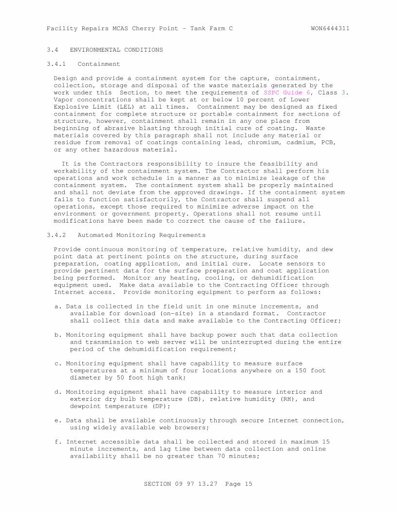
Facility Repairs MCAS Cherry Point - Tank Farm C WON6444311
3.4 ENVIRONMENTAL CONDITIONS
3.4.1 Containment
Design and provide a containment system for the capture, containment, collection, storage and disposal of the waste materials generated by the work under this Section, to meet the requirements of SSPC Guide 6 , Class 3. Vapor concentrations shall be kept at or below 10 percent of Lower Explosive Limit (LEL) at all times. Containment may be designed as fixed containment for complete structure or portable containment for sections of structure, however, containment shall remain in any one place from beginning of abrasive blasting through initial cure of coating. Waste materials covered by this paragraph shall not include any material or residue from removal of coatings containing lead, chromium, cadmium, PCB, or any other hazardous material.
It is the Contractors responsibility to insure the feasibility and workability of the containment system. The Contractor shall perform his operations and work schedule in a manner as to minimize leakage of the containment system. The containment system shall be properly maintained and shall not deviate from the approved drawings. If the containment system fails to function satisfactorily, the Contractor shall suspend all operations, except those required to minimize adverse impact on the environment or government property. Operations shall not resume until modifications have been made to correct the cause of the failure.
3.4.2 Automated Monitoring Requirements
Provide continuous monitoring of temperature, relative humidity, and dew point data at pertinent points on the structure, during surface preparation, coating application, and initial cure. Locate sensors to provide pertinent data for the surface preparation and coat application being performed. Monitor any heating, cooling, or dehumidification equipment used. Make data available to the Contracting Officer through Internet access. Provide monitoring equipment to perform as follows:
a. Data is collected in the field unit in one minute increments, and available for download (on-site) in a standard format. Contractor shall collect this data and make available to the Contracting Officer;
b. Monitoring equipment shall have backup power such that data collection and transmission to web server will be uninterrupted during the entire period of the dehumidification requirement;
c. Monitoring equipment shall have capability to measure surface temperatures at a minimum of four locations anywhere on a 150 foot diameter by 50 foot high tank;
d. Monitoring equipment shall have capability to measure interior and exterior dry bulb temperature (DB), relative humidity (RH), and dewpoint temperature (DP);
e. Data shall be available continuously through secure Internet connection, using widely available web browsers;
f. Internet accessible data shall be collected and stored in maximum 15 minute increments, and lag time between data collection and online availability shall be no greater than 70 minutes;
SECTION 09 97 13.27 Page 15

Facility Repairs MCAS Cherry Point - Tank Farm C WON6444311
g. Internet accessible data shall be available for viewing online in tabular format, and graphical format using selected data;
h. Internet accessible data shall be available for download in user-defined segments, or entire project to date, in a standard format usable by Microsoft Excel and other spreadsheet programs.
i. Internet-based controls shall provide alerts to pre-designated parties through email messaging;
j. Internet-based controls shall monitor data uploads from field unit and issue alert if data not initiated within 60 minutes of last upload;
k. Internet-based controls shall monitor operation of DH equipment and issues alert when power remains off for more than 15 seconds, or if pre-determined temperature, RH, or DP conditions are exceeded;
The requirements listed here were developed around the Munters Exactaire Monitoring System, as this was the only monitoring system having Internet connectivity known to be commercially available. There is no requirement for connectivity of the monitoring system to control the DH equipment, therefore, any combination of equipment having the required functionality will be accepted.
3.5 SURFACE PREPARATION
3.5.1 Abrasive Blasting Equipment
Use abrasive blasting equipment of conventional air, force-feed, or pressure type. Maintain a minimum pressure of 95 psig at nozzle. Confirm that air supply for abrasive blasting is free of oil and moisture when tested in accordance with ASTM D4285. Test air quality at each startup, but in no case less often than every five operating hours.
3.5.2 Operational Evaluation of Abrasive
Test abrasive for salt contamination and oil contamination as required by the appropriate abrasive specification daily at startup and every five operating hours thereafter.
3.5.3 Surface Standard
Inspect surfaces to be coated, and select plate with similar properties and surface characteristics for use as a surface standard. Blast clean one or more 1 foot square steel panels as specified in paragraph SURFACE PREPARATION. Record blast nozzle type and size, air pressure at nozzle and compressor, distance of nozzle from panel, and angle of blast to establish procedures for blast cleaning. Measure surface profile in accordance with ASTM D7127. When the surface standard complies with all specified requirements, seal with a clearcoat protectant. Use the surface standard for comparison to abrasive blasted surfaces throughout the course of work.
3.5.4 Pre-Preparation Testing for Surface Contamination
Perform testing, abrasive blasting, and testing in the prescribed order.
3.5.4.1 Pre-Preparation Testing for Oil and Grease Contamination
Inspect all surfaces for oil and/or grease contamination using two or more
SECTION 09 97 13.27 Page 16

Facility Repairs MCAS Cherry Point - Tank Farm C WON6444311
of the following inspection techniques: 1) Visual inspection, 2) WATER BREAK TEST, 3) CLOTH RUB TEST. Reject oil and/or grease contaminated surfaces, clean in accordance with SSPC SP 1 , and recheck for contamination until surfaces are free of oil and grease.
WATER BREAK TEST - Spray atomized mist of distilled water onto surface, and observe for water beading. If water "wets" surface rather than beading up, surface can be considered free of oil or grease contamination. Beading of water (water forms droplets) is evidence of oil or grease contamination.
CLOTH RUB TEST - Rub a clean, white, lint free, cotton cloth onto surface and observe for discoloration. To confirm oil or grease contamination in lightly stained areas, a non-staining solvent may be used to aid in oil or grease extraction. Any visible discoloration is evidence of oil or grease contamination.
3.5.4.2 Pre-Preparation Testing for Soluble Salts Contamination
Test surfaces for soluble salts, and wash as required, prior to abrasive blasting. Soluble salt testing is also required in paragraph PRE-APPLICATION TESTING FOR SOLUBLE SALTS CONTAMINATION as a final acceptance test of prepared surfaces after abrasive blasting, and successful completion of this phase does not negate that requirement. This phase is recommended since pre-preparation testing and washing are generally more advantageous than attempting to remove soluble salt contamination after abrasive blasting. Effective removal of soluble salts will require removal of any barrier to the steel surface, including rust. This procedure may necessitate combinations of wet abrasive blasting, high pressure water rinsing, and cleaning using a solution of water washing and soluble salts remover. The soluble salts remover shall be acidic, biodegradable, nontoxic, noncorrosive, and after application, will not interfere with primer adhesion. Delays between testing and preparation, or testing and coating application, may allow for the formation of new contamination. Use potable water, or potable water modified with soluble salt remover, for all washing or wet abrasive blasting. Test methods and equipment used in this phase are selected at the Contractor's discretion.
3.5.5 Abrasive Blasting
Abrasive blast steel surfaces to near-white metal in accordance with SSPC SP 10/NACE No. 2 . Prepared surfaces shall conform to SSPC VIS 1 and shall match the prepared test-panels. Provide a 2 to 3 mil surface profile. Reject profile greater than 3 mils , discontinue abrasive blasting, and modify processes and materials to provide the specified profile. Measure surface profile in accordance with ASTM D7127, using Rmax as the measure of profile height. Record all measurements required in this standard. Measure profile at rate of three test areas for the first 1000 square feet plus one test area for each additional 1000 square feet or part thereof. When surfaces are reblasted for any reason, retest profile as specified. Following abrasive blasting, remove dust and debris by vacuum cleaning. Do not attempt to wipe surface clean.
3.5.6 Disposal of Used Abrasive
Dispose of used abrasive off Government property in accordance with Federal, State, and Local mandated regulations.
SECTION 09 97 13.27 Page 17

Facility Repairs MCAS Cherry Point - Tank Farm C WON6444311
3.5.7 Pre-Application Testing For Surface Contamination
3.5.7.1 Pre-Application Testing for Oil and Grease Contamination
Ensure surfaces are free of contamination as described in paragraph PRE-PREPARATION TESTING FOR OIL AND GREASE CONTAMINATION, except that only questionable areas need be checked for beading of water misted onto surface.
3.5.7.2 Pre-Application Testing for Soluble Salts Contamination
Test surfaces for chloride contamination using the Test Kit described in TEST KIT FOR MEASURING CHLORIDE, SULFATE AND NITRATE IONS ON STEEL AND COATED SURFACES. Test all surfaces at rate of three tests for the first 1000 square feet plus one test for each additional 2000 square feet or part thereof. Perform 30 percent of tests on bare steel at welds, divided equally between horizontal and vertical welds. One or more readings greater than 3 micrograms per square centimeter of chlorides or 10 micrograms per square centimeter of sulfates or 5 micrograms per square centimeter of nitrates is evidence of soluble salt contamination. Reject contaminated surfaces, wash as discussed in paragraph PRE-PREPARATION TESTING FOR SOLUBLE SALTS CONTAMINATION, allow to dry, and re-test until all required tests show allowable results. Reblast tested and cleaned areas as required. Label all test tubes and retain for test verification.
3.5.7.3 Pre-Application Testing for Surface Cleanliness
Apply coatings to dust free surfaces. To test surfaces, apply strip of clear adhesive tape to surface and rub onto surface with finger. When removed, the tape should show little or no dust, blast abrasive, or other contaminant. Reject contaminated surfaces and retest. Test surfaces at rate of three tests for the first 1000 square feet plus one test for each additional 1000 square feet or part thereof. Provide two additional tests for each failed test or questionable test. Attach test tapes to Daily Inspection Reports.
3.6 MIXING AND APPLICATION OF SEALANT AND COATING SYSTEM
3.6.1 Preparation of Sealant and Coating Materials for Application
Each of the sealant, primer, intermediate, and topcoat materials is a two-component material supplied in separate containers.
3.6.1.1 Mixing Sealant, Primer and Intermediate Coat Materials
Mix in accordance with manufacturer's instructions, which may differ for each product. Do not mix partial kits, or alter mix ratios. Mix materials in same temperature and humidity conditions specified in paragraph DELIVERY AND STORAGE. Allow mixed material to stand for the required induction time based on its temperature.
3.6.1.2 Mixing Topcoat Material
Do not mix partial kits, or alter mix ratios. Mix polyurethane coating materials in same temperature conditions specified in paragraph DELIVERY AND STORAGE. The polyurethane coating material is moisture sensitive and any introduction of moisture or water into the material during mixing or application will shorten usable pot life. Use a mixer that does not create a vortex. Do not add solvent without specific written recommendation from the manufacturer. No induction time is required, only thorough agitation
SECTION 09 97 13.27 Page 18

Facility Repairs MCAS Cherry Point - Tank Farm C WON6444311
of the mixed material.
3.6.1.3 Pot Life
Apply mixed products within stated pot life for each product. Stop applying when material becomes difficult to apply in a smooth, uniform wet film. Add all required solvent at time of mixing. Do not add solvent to extend pot life. Pot life is based on standard conditions at 70 degrees F and 50 percent relative humidity. For every 18 degrees F rise in temperature, pot life is reduced by approximately half, and for every 18 degrees F drop it is approximately doubled. Usable pot life depends on the temperature of the material at the time of mixing and the sustained temperature at the time of application. Other factors such as the shape of the container and volume of mixed material may also affect pot life. Precooling or exterior icing of components for at least 24 hours to a minimum of 50 degrees F in hot climates will extend pot life. High humidity at time of mixing and application shortens pot life of the Polyurethane topcoat material. Following are approximate pot life times:
Sealant As specified by manufacturerEpoxy primer and intermediate materials 4 hoursPolyurethane topcoat materials 2 hours.
3.6.1.4 Application Conditions and Recoat Windows
The application condition requirements for the coating system are very time and temperature sensitive, and are intended to avoid the delamination problems frequently found on industrial structures. Plan coating application to ensure that specified temperature, humidity, and condensation conditions are met. If conditions do not allow for orderly application of sealant, primer, stripe coat, intermediate coat and topcoat, use appropriate means of controlling air and surface temperatures, as required. Partial or total enclosures, insulation, heating or cooling, or other appropriate measures may be required to control conditions to allow for orderly application of all required coats.
Maintain air and steel surface temperature between 60 and 100 degrees F during application and the first four hours of cure for epoxy coats and the first eight hours of cure for polyurethane coats. Maintain steel surface temperature more than 5 degrees F above the dew-point of the ambient air for the same period.
Use Table entitled "RECOAT WINDOWS" to determine appropriate recoat windows for each coat after the initial coat. Apply each coat during appropriate RECOAT WINDOW of preceding coat. If a RECOAT WINDOW is missed, the minimum and maximum primer and intermediate coat thickness may be adjusted to accommodate a FILL COAT, however, requirements for total epoxy coating thickness and total coating thickness will not be modified. Missing more than one RECOAT WINDOW may require complete removal of coating if maximum total coating thickness requirements cannot be achieved.
If coating is not applied during RECOAT WINDOW, or if surface temperature exceeds 120 degrees F between applications, provide GLOSS REMOVAL, apply next coat within 24 hours. If next planned coat is topcoat, apply FILL COAT if required to fill sanding marks. Sanding marks from GLOSS REMOVAL of intermediate coat reflecting through topcoat will be considered as noncompliant. Apply FILL COAT within 24 hours of GLOSS REMOVAL, then apply topcoat within RECOAT WINDOW of FILL COAT.
SECTION 09 97 13.27 Page 19
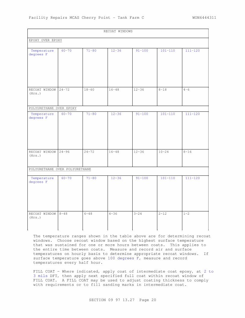
Facility Repairs MCAS Cherry Point - Tank Farm C WON6444311
RECOAT WINDOWS
EPOXY OVER EPOXY
Temperature degrees F
60-70 71-80 12-36 91-100 101-110 111-120
RECOAT WINDOW (Hrs.)
24-72 18-60 16-48 12-36 8-18 4-6
POLYURETHANE OVER EPOXY
Temperature degrees F
60-70 71-80 12-36 91-100 101-110 111-120
RECOAT WINDOW (Hrs.)
24-96 24-72 16-48 12-36 10-24 8-16
POLYURETHANE OVER POLYURETHANE
Temperature degrees F
60-70 71-80 12-36 91-100 101-110 111-120
RECOAT WINDOW (Hrs.)
8-48 6-48 4-36 3-24 2-12 1-2
The temperature ranges shown in the table above are for determining recoat windows. Choose recoat window based on the highest surface temperature that was sustained for one or more hours between coats. This applies to the entire time between coats. Measure and record air and surface temperatures on hourly basis to determine appropriate recoat windows. If surface temperature goes above 100 degrees F , measure and record temperatures every half hour.
FILL COAT - Where indicated, apply coat of intermediate coat epoxy, at 2 to 3 mils DFT, then apply next specified full coat within recoat window of FILL COAT. A FILL COAT may be used to adjust coating thickness to comply with requirements or to fill sanding marks in intermediate coat.
SECTION 09 97 13.27 Page 20

Facility Repairs MCAS Cherry Point - Tank Farm C WON6444311
GLOSS REMOVAL - Where required, hand sand in a linear fashion to remove gloss using 120-200 grit wet/dry sandpaper, followed by solvent wiping with a clean rag soaked with denatured alcohol to remove all dust. GLOSS REMOVAL of primer coat is to scarify surface and shall consist of removal of approximately 1 mil of coating. If steel is exposed during GLOSS REMOVAL, repair in accordance with paragraph PROCEDURE FOR HOLIDAY AND SPOT REPAIRS OF NEWLY APPLIED COATING. GLOSS REMOVAL of intermediate coat may include removal of up to 3 mils of coating to avoid excess thickness, prior to application of FILL COAT.
3.6.2 Amine Blush Testing of Epoxy Coat Prior to Overcoating
Test epoxy surfaces prior to application of roof joint sealant, epoxy coat, or polyurethane topcoat for amine blush contamination using the Test Kit described in paragraph TEST KIT FOR IDENTIFYING AMINE BLUSH ON EPOXY SURFACES. Test all surfaces at rate of three tests for the first 1000 square feet plus one test for each additional 2000 square feet or part thereof. Remove any identified contamination using an approved procedure.
3.6.3 Application of Coating System and Joint Sealant
Apply coatings in accordance with SSPC PA 1 and as specified herein. Apply coatings to surfaces that meet all stated surface preparation requirements.
After application of primer coat and prior to application of each subsequent coat, perform testing prescribed in paragraph PRE-APPLICATION TESTING FOR SURFACE CONTAMINATION, as necessary, to ensure minimal intercoat contamination. This testing may be reduced to one half of the prescribed rate for bare steel if the testing indicates no contamination when sampling is evenly distributed over surfaces being tested. If contamination is found between coats, revert to the specified testing rate. Generally, oil and grease contamination and soluble salts contamination are not encountered if subsequent coats are applied within specified recoat windows and unusual atmospheric events do not occur. Such atmospheric events as a coastal storm blowing onshore can bring unusual chloride contamination. Concern for intercoat contamination should be continually prevalent, and spot testing should be accomplished to verify satisfactory conditions. Where visual examination or spot testing indicates contamination, perform sufficient testing to verify non-contamination, or to define extent of contamination for appropriate treatment.
Apply each coat in a consistent wet film, at 90 degrees to previous coat. Ensure that primer and intermediate coat "cold joints" are no less than six inches from welds. Apply stripe coat by brush. For convenience, stripe coat material may be delivered by spray if followed immediately with brush-out and approved procedures include appropriate controls on thickness. Apply all other coats by spray application. Use appropriate controls to prevent airborne coating fog from drifting beyond 15 feet from the structure perimeter or the tank berm. Cover or protect all surfaces that will not be coated. The cleanliness, temperature, recoat windows, and airborne paint containment requirements may necessitate the use of enclosures, portable shelters, or other appropriate controls.
Apply coatings at the following specified thickness:
SECTION 09 97 13.27 Page 21

Facility Repairs MCAS Cherry Point - Tank Farm C WON6444311
Coat Minimum DFT (Mils) Maximum DFT (Mils)
Primer 3 5
Intermediate 3 5
Top 2 3
Total system 8 13
3.6.3.1 Application of Primer
Apply primer coat, maintaining paint supply container height within 3 feet of the paint nozzle for applying zinc primer. Maintain constant agitation of paint pot to ensure that zinc does not settle in container.
3.6.3.2 Application of Stripe Coat
Apply a stripe coat of intermediate coat epoxy material within RECOAT WINDOW of primer, allowing sufficient dry time to allow application of intermediate coat within RECOAT WINDOW of primer. Apply by brush, working material into corners, crevices, angles, and welds, and onto outside corners and angles.
3.6.3.3 Application of Intermediate Coat
Apply intermediate coat within RECOAT WINDOW of primer coat.
3.6.3.4 Non-skid for Stairs and Top
Where non-skid is required, apply a second intermediate coat, and immediately follow with application of non-skid grit, broadcast at the rate of 2 pounds per 100 square feet, and backroll. Apply topcoat as specified.
3.6.3.5 Application of Topcoat
Make all required repairs to primer and intermediate coats as specified in paragraph entitled "Procedure for Holiday and Spot Repairs of Newly Applied Coating" prior to applying topcoat. Apply topcoat within RECOAT WINDOW of intermediate coat. The polyurethane topcoat may require multiple passes to achieve desired aesthetics and required thickness. Consult manufacturer for thinning and application procedures for anticipated temperature, humidity, and wind conditions. Touch-up blemishes and defects within recoat window of polyurethane topcoat. Retain sample of polyurethane topcoat, from the same batch used to coat structure, to make touch-ups that might be required later.
3.6.3.6 Application of Joint Sealant
Apply joint sealant to back-to-back steel joints that are less that 3/8 inches wide and are not seal welded. Apply sealant to top and bottom, or each side, of narrow joints. Apply sealant within 48 hours of application of the topcoat, and touch-up with topcoat after appropriate cure of the sealant.
3.6.3.7 Procedure for Holiday and Spot Repairs of Newly Applied Coating
Repair coating film defects at the earliest practicable time, preferably
SECTION 09 97 13.27 Page 22

Facility Repairs MCAS Cherry Point - Tank Farm C WON6444311
before application of the succeeding coat. Observe all requirements for soluble salts contamination, cleanliness between coats, and application conditions. Prepare defective area in accordance with SSPC SP 10/NACE No. 2 , and feather coating as required to leave 4 inches of each succeeding coat feathered and abraded. Protect adjacent areas from damage and overspray. Remove dust and solvent wipe the prepared area plus an additional 4 inches beyond the prepared area with clean denatured alcohol. Apply each coat within RECOAT WINDOW of preceeding coat. Within four hours of preparation, apply zinc-rich primer to prepared steel and feather onto prepared primer. Apply intermediate coat to primed area and feather to prepared intermediate area. Apply topcoat to intermediate coat and feather to prepared topcoat. Apply each repair coat to approximate thickness of surrounding coating system.
3.6.3.8 Structure Occupancy After Coating Application
Use clean canvas or other approved shoe covers when walking on coated surfaces, regardless of curing time allowed. For heavily trafficked areas, provide cushioned mats for additional protection.
3.7 PROJECT IDENTIFICATION
At the completion of the work, stencil the following information on the tank exterior adjacent to the main manway opening in 3/4 to one inch Helvetica style letters of contrasting color using acrylic stencil paint:
Date exterior coated:Project Number:Contractor:Address:Coating System
Surface Prep: SSPC SP ____ Profile: ______Primer: __________________ Thickness: ____Intermediate: ____________ Thickness: ____Topcoat: _________________ Thickness: ____Total Thickness: _________
3.8 FIELD QUALITY CONTROL
For marking of tank surfaces, use chalk for marking bare steel, and water based markers for marking coated surfaces, and remove marks prior to coating. Do not use any wax or grease based markers, or any other markers that leave a residue or stain.
3.8.1 Coating Inspector
The coating inspector shall be considered a QC Specialist and shall report to the QC Manager, as specified in Section 01 45 00.00 20 QUALITY CONTROL. The Coating Inspector shall be present during all pre-preparation testing, surface preparation, coating application, initial cure of the coating system, during all coating repair work, and during completion activities as specified in Section 01 45 00.00 20 QUALITY CONTROL. The Coating Inspector shall provide complete documentation of conditions and occurrences on the job site, and be aware of conditions and occurrences that are potentially detrimental to the coating system. The requirements for inspection listed in this Section are in addition to the QC inspection and reporting requirements specified in Section 01 45 00.00 20 QUALITY CONTROL.
SECTION 09 97 13.27 Page 23
Facility Repairs MCAS Cherry Point - Tank Farm C WON6444311
3.8.2 Field Inspection
3.8.2.1 Inspection Requirements
Perform field inspection in accordance with ASTM D3276 and the approved Coating Work Plan. Document Contractor's compliance with the approved Coating Work Plan.
Provide all tools and instruments required to perform the required testing, as well as any tools or instruments that the inspector considers necessary to perform the required inspections and tests. Document each inspection and test, including required hold points and other required inspections and tests, as well as those inspections and tests deemed prudent from on-site evaluation to document a particular process or condition, as follows:
a. Location or area; b. Purpose (required or special);c. Method;d. Criteria for evaluation;e. Results;f. Determination of compliance;g. List of required rework;h. Observations.
Collect and record Environmental Conditions as described in ASTM D3276 on a 24 hour basis, as follows:
a. During surface preparation, every two hours or when changes occur;b. During coating application and the first four days of initial cure,
every hour, or when changes occur;c. Note location, time, and temperature of the highest and lowest surface
temperatures each day;d. Use a non-contact thermometer to locate temperature extremes, then
verify with contact thermometers.
Document all equipment used in inspections and testing, including manufacturer, model number, serial number, last calibration date and future calibration date, and results of on-site calibration performed.
Document Contractors compliance with the approved Coating Work Plan.
3.8.2.2 Inspection Report Forms
Develop project-specific report forms as required to report measurements, test results, and observations being complete and and conforming to contract requirements. This includes all direct requirements of the contract documents and indirect requirements of referenced documents. Show acceptance criteria with each requirement and indication of conformity of each inspected item. The data may be in any format, but must be legible and presented so that entered data can be quickly compared to the appropriate requirement.
3.8.2.3 Daily Inspection Reports
Submit one copy of daily inspection report completed each day when performing work under this Section, to the Contracting Officer. Note all non-compliance issues, and all issues that were reported for rework in accordance with QC procedures of Section 01 45 00.00 20 QUALITY CONTROL. Each report shall be signed by the coating inspector and the QC Manager.
SECTION 09 97 13.27 Page 24

Facility Repairs MCAS Cherry Point - Tank Farm C WON6444311
Submit report within 24 hours of date recorded on the report.
3.8.2.4 Inspection Logbook
A continuous record of all activity related to this Section shall be maintained in an Inspection Logbook on a daily basis. The logbook shall be hard or spiral bound with consecutively numbered pages, and shall be used to record all information provided in the Daily Inspection Reports, as well as other pertinent observations and information. The Coating Inspector's Logbook that is sold by NACE is satisfactory. Submit the original Inspection Logbook to the Contracting Officer upon completion of the project and prior to final payment.
3.8.2.5 Inspection Equipment
All equipment shall be in good condition, operational within its design range, and calibrated as required by the specified standard for use of each device.
3.9 FINAL CLEANUP
Following completion of the work, remove debris, equipment, and materials from the site. Remove temporary connections to Government or Contractor furnished water and electrical services. Restore existing facilities in and around the work areas to their original condition.
TABLE 1
COATING QUALITY CONFORMANCE INSPECTION REQUIREMENTS
Table Ia - Zinc-rich Epoxy Primer Coat MIL-DTL-24441/19 Formula 159
Test Componenent A Component B Mixed
Min. Max. Min. Max. Min. Max.
Pigment content, percent (zinc dust)
--- --- 81.5 85.5 --- ---
Volatiles, percent 42.8 44.3 8.0 8.4 --- ---
Non-volatile vehicle percent
53.7 57.7 8.3 8.7 --- ---
Weight, Kilograms/liter 0.87 1.01 3.30 3.40 2.80 2.91
Weight, Pounds/gallon 7.3 8.4 27.5 28.4 23.4 24.4
Flashpoint, Degrees C 35.6 --- 37.8 --- --- ---
SECTION 09 97 13.27 Page 25

Facility Repairs MCAS Cherry Point - Tank Farm C WON6444311
TABLE 1
COATING QUALITY CONFORMANCE INSPECTION REQUIREMENTS
Table Ia - Zinc-rich Epoxy Primer Coat MIL-DTL-24441/19 Formula 159
Test Componenent A Component B Mixed
Min. Max. Min. Max. Min. Max.
Flashpoint, Degrees F 96 --- 100 --- --- ---
Consistency, grams --- --- 250 500 150 300
Set to touch time, hours at 23 degrees C, 73 degrees F
--- --- --- --- --- 2
Dry hard time, hours at 23 degrees C, 73 degrees F
--- --- --- --- --- 8
Pot life, hours at 23 degrees C, 73 degrees F
--- --- --- --- 4 ---
Sag resistance, Micrometers
--- --- --- --- 300 ---
Sag resistance, Mils --- --- --- --- 12 ---
VOC, Grams/liter --- --- --- --- --- 304
VOC, Pounds/gallon --- --- --- --- --- 2.5
NOTES: Test methods as specified in MIL-DTL-24441 .
SECTION 09 97 13.27 Page 26

Facility Repairs MCAS Cherry Point - Tank Farm C WON6444311
TABLE 1
COATING QUALITY CONFORMANCE INSPECTION REQUIREMENTS
Table Ib. - Epoxy Intermediate Coat MIL-DTL-24441/31 Formula 152 Type IV (White (Tinted))
Test Componenent A Component B Mixed
Min. Max. Min. Max. Min. Max.
Pigment content, percent 44.0 49.0 33.0 38.0 --- ---
Volatiles, percent 29.0 35.0 16.0 21.0 --- ---
Non-volatile vehicle percent
17.5 23.5 44.0 49.0 --- ---
Coarse particles, percent --- 0.3 --- 0.3 --- ---
Consistency, grams 180 320 300 470 180 245
Weight, Kilograms/liter 1.39 1.45 1.29 1.35 1.34 1.4
Weight, Pounds/gallon 11.6 12.1 10.8 11.3 11.2 11.7
Set to touch time, hours at 23 degrees C, 73 degrees F
--- --- --- --- --- 3
Dry hard time, hours at 23 degrees C, 73 degrees F
--- --- --- --- --- 8
Fineness of grind, Hegman 4 --- 4 --- --- ---
Flashpoint, Degrees C 35.5 --- 37.8 --- --- ---
Flashpoint, Degrees F 96 --- 100 --- --- ---
Titanium dioxide, percent of pigment
91 --- --- --- --- ---
Pot life, hours at 23 degrees C, 73 degrees F
--- --- --- --- 4 ---
Sag resistance, Micrometers
--- --- --- --- 300 ---
Sag resistance, Mils --- --- --- --- 12 ---
SECTION 09 97 13.27 Page 27

Facility Repairs MCAS Cherry Point - Tank Farm C WON6444311
TABLE 1
COATING QUALITY CONFORMANCE INSPECTION REQUIREMENTS
Table Ib. - Epoxy Intermediate Coat MIL-DTL-24441/31 Formula 152 Type IV (White (Tinted))
Test Componenent A Component B Mixed
Min. Max. Min. Max. Min. Max.
Color of dry film to approximate color of FED-STD-595 color 27778
--- --- --- --- --- Conform
Contrast ratio, at 75 micrometers, 3 mils DFT
--- --- --- --- .098 ---
Gloss, 60 degree specular --- --- --- --- 35 ---
VOC, Grams/liter --- --- --- --- --- 340
VOC, Pounds/gallon --- --- --- --- --- 2.8
GENERAL NOTES: Test methods as specified in MIL-DTL-24441 .Where "Conform" is indicated, refer to specific requirements of MIL-DTL-24441/31 .
TABLE I
COATING QUALITY CONFORMANCE INSPECTION REQUIREMENTS
Table Ic - Polyurethane Topcoat MIL-PRF-85285 Type II (White and Colors)
Test Componenent A Component B Mixed
Min. Max. Min. Max. Min. Max.
Moisture content, percent --- 2 --- --- --- ---
Course particles, percent --- --- --- --- --- .5
Viscosity --- --- --- --- --- See Note 1
Fineness of grind, Hegman --- --- --- --- 7 ---
SECTION 09 97 13.27 Page 28

Facility Repairs MCAS Cherry Point - Tank Farm C WON6444311
TABLE I
COATING QUALITY CONFORMANCE INSPECTION REQUIREMENTS
Table Ic - Polyurethane Topcoat MIL-PRF-85285 Type II (White and Colors)
Test Componenent A Component B Mixed
Min. Max. Min. Max. Min. Max.
Drying to touch (See Note 2) --- --- --- --- --- 4
Dry-hard (See Note 2) --- --- --- --- --- 8
VOC, grams per liter --- --- --- --- --- 340
Color --- --- --- --- delta E+-1.0
Gloss 60 degree specular gloss
Gloss --- --- --- --- --- 90
Semi-gloss --- --- --- --- 15 45
Opacity --- --- --- --- 0.95 ---
Flexibility --- --- --- --- --- Conform
Fluid resistance --- --- --- --- --- Conform
Heat resistance (cure) --- --- --- --- --- Conform
Solvent resistance (cure) --- --- --- --- --- Conform
Condition in container --- --- --- --- --- Conform
Odor --- --- --- --- --- Conform
Lead percent --- --- --- --- --- 0.06
Cadmium percent --- --- --- --- --- 0.06
Chromium percent--- --- --- --- --- 0.00
SECTION 09 97 13.27 Page 29

Facility Repairs MCAS Cherry Point - Tank Farm C WON6444311
TABLE I
COATING QUALITY CONFORMANCE INSPECTION REQUIREMENTS
Table Ic - Polyurethane Topcoat MIL-PRF-85285 Type II (White and Colors)
Test Componenent A Component B Mixed
Min. Max. Min. Max. Min. Max.
NOTES:(1) Modify paragraph 3.6.4 Viscosity and Pot Life, of MIL-PRF-85285 as follows:
The viscosity of the admixed coating, when tested in accordance with ASTM D1200 through a No. 4 Ford cup, shall be as follows:
Time from mix (minimum) Maximum time through a No. 4 FordCup
Initially 30 seconds
2 hours 60 seconds
4 hours No gel
(2) Modify paragraph 3.7.1 Drying Time, of MIL-PRF-85285 .When applied by spray techniques and when tested in accordance with ASTM D1640/D1640M, the coating shall be set-to-touch within four hours and dry-hard within eight hours (see 4.6 and table I).
GENERAL NOTES:Test methods as specified in MIL-PRF-85285 , except those marked with "*".Where "Conform" is indicated, refer to specific requirements of MIL-PRF-85285 .
-- End of Section --
SECTION 09 97 13.27 Page 30
Facility Repairs MCAS Cherry Point - Tank Farm C WON6444311
SECTION 22 00 00
PLUMBING, GENERAL PURPOSE11/11
PART 1 GENERAL
1.1 REFERENCES
The publications listed below form a part of this specification to the extent referenced. The publications are referred to within the text by the basic designation only.
AMERICAN NATIONAL STANDARDS INSTITUTE (ANSI)
ANSI Z21.22/CSA 4.4 (1999; Addenda A 2000, Addenda B 2001; R 2004) Relief Valves for Hot Water Supply Systems
AMERICAN SOCIETY OF HEATING, REFRIGERATING AND AIR-CONDITIONING ENGINEERS (ASHRAE)
ASHRAE 90.1 - IP (2010; INT 1 2011; Errata 2011, Errata 2011; Errata 2011, INT 2-12 2011, Errata 2011; INT 13 2012; INT 14 2012) Energy Standard for Buildings Except Low-Rise Residential Buildings
AMERICAN SOCIETY OF SANITARY ENGINEERING (ASSE)
ASSE 1003 (2009) Performance Requirements for Water Pressure Reducing Valves for Domestic Water Distribution Systems - (ANSI approved 2010)
ASSE 1018 (2001) Performance Requirements for Trap Seal Primer Valves - Potable Water Supplied (ANSI Approved 2002
AMERICAN WATER WORKS ASSOCIATION (AWWA)
AWWA 10084 (2005) Standard Methods for the Examination of Water and Wastewater
AWWA B300 (2010; Addenda 2011) Hypochlorites
AWWA B301 (2010) Liquid Chlorine
AWWA C203 (2008) Coal-Tar Protective Coatings and Linings for Steel Water Pipelines - Enamel and Tape - Hot-Applied
AWWA C606 (2011) Grooved and Shouldered Joints
AWWA C651 (2005; Errata 2005) Standard for Disinfecting Water Mains
AWWA C652 (2011) Disinfection of Water-Storage
SECTION 22 00 00 Page 1

Facility Repairs MCAS Cherry Point - Tank Farm C WON6444311
Facilities
AMERICAN WELDING SOCIETY (AWS)
AWS A5.8/A5.8M (2011) Specification for Filler Metals for Brazing and Braze Welding
AWS B2.2/B2.2M (2010) Specification for Brazing Procedure and Performance Qualification
ASME INTERNATIONAL (ASME)
ASME A112.14.1 (2003; R 2008) Backwater Valves
ASME A112.6.1M (1997; R 2008) Floor Affixed Supports for Off-the-Floor Plumbing Fixtures for Public Use
ASME B1.20.1 (1983; R 2006) Pipe Threads, General Purpose (Inch)
ASME B16.12 (2009) Cast Iron Threaded Drainage Fittings
ASME B16.15 (2011) Cast Bronze Alloy Threaded Fittings Classes 125 and 250
ASME B16.18 (2012) Cast Copper Alloy Solder Joint Pressure Fittings
ASME B16.21 (2011) Nonmetallic Flat Gaskets for Pipe Flanges
ASME B16.22 (2001; R 2010) Standard for Wrought Copper and Copper Alloy Solder Joint Pressure Fittings
ASME B16.23 (2011) Cast Copper Alloy Solder Joint Drainage Fittings - DWV
ASME B16.24 (2011) Cast Copper Alloy Pipe Flanges and Flanged Fittings: Classes 150, 300, 600, 900, 1500, and 2500
ASME B16.29 (2012) Wrought Copper and Wrought Copper Alloy Solder Joint Drainage Fittings - DWV
ASME B16.3 (2011) Malleable Iron Threaded Fittings, Classes 150 and 300
ASME B16.34 (2009; Supp 2010) Valves - Flanged, Threaded and Welding End
ASME B16.39 (2009) Standard for Malleable Iron Threaded Pipe Unions; Classes 150, 250, and 300
ASME B16.4 (2011) Standard for Gray Iron Threaded Fittings; Classes 125 and 250
SECTION 22 00 00 Page 2

Facility Repairs MCAS Cherry Point - Tank Farm C WON6444311
ASME B16.5 (2009) Pipe Flanges and Flanged Fittings: NPS 1/2 Through NPS 24 Metric/Inch Standard
ASME B16.50 (2001; R 2008) Wrought Copper and Copper Alloy Braze-Joint Pressure Fittings
ASME B31.1 (2012) Power Piping
ASME B31.5 (2010) Refrigeration Piping and Heat Transfer Components
ASME B40.100 (2005; R 2010) Pressure Gauges and Gauge Attachments
ASME BPVC SEC IV (2010) BPVC Section IV-Rules for Construction of Heating Boilers
ASME BPVC SEC IX (2010) BPVC Section IX-Welding and Brazing Qualifications
ASME CSD-1 (2012) Control and Safety Devices for Automatically Fired Boilers
ASTM INTERNATIONAL (ASTM)
ASTM A105/A105M (2011a) Standard Specification for Carbon Steel Forgings for Piping Applications
ASTM A183 (2003; R 2009) Standard Specification for Carbon Steel Track Bolts and Nuts
ASTM A193/A193M (2012a) Standard Specification for Alloy-Steel and Stainless Steel Bolting Materials for High-Temperature Service and Other Special Purpose Applications
ASTM A47/A47M (1999; R 2009) Standard Specification for Ferritic Malleable Iron Castings
ASTM A515/A515M (2010) Standard Specification for Pressure Vessel Plates, Carbon Steel, for Intermediate- and Higher-Temperature Service
ASTM A516/A516M (2010) Standard Specification for Pressure Vessel Plates, Carbon Steel, for Moderate- and Lower-Temperature Service
ASTM A518/A518M (1999; R 2008) Standard Specification for Corrosion-Resistant High-Silicon Iron Castings
ASTM A53/A53M (2012) Standard Specification for Pipe, Steel, Black and Hot-Dipped, Zinc-Coated, Welded and Seamless
ASTM A536 (1984; R 2009) Standard Specification for Ductile Iron Castings
SECTION 22 00 00 Page 3

Facility Repairs MCAS Cherry Point - Tank Farm C WON6444311
ASTM A733 (2003e1; R 2009) Standard Specification for Welded and Seamless Carbon Steel and Austenitic Stainless Steel Pipe Nipples
ASTM A74 (2009) Standard Specification for Cast Iron Soil Pipe and Fittings
ASTM A888 (2011) Standard Specification for Hubless Cast Iron Soil Pipe and Fittings for Sanitary and Storm Drain, Waste, and Vent Piping Applications
ASTM B117 (2011) Standard Practice for Operating Salt Spray (Fog) Apparatus
ASTM B152/B152M (2009) Standard Specification for Copper Sheet, Strip, Plate, and Rolled Bar
ASTM B306 (2009) Standard Specification for Copper Drainage Tube (DWV)
ASTM B32 (2008) Standard Specification for Solder Metal
ASTM B370 (2011e1) Standard Specification for Copper Sheet and Strip for Building Construction
ASTM B42 (2010) Standard Specification for Seamless Copper Pipe, Standard Sizes
ASTM B43 (2009) Standard Specification for Seamless Red Brass Pipe, Standard Sizes
ASTM B584 (2011) Standard Specification for Copper Alloy Sand Castings for General Applications
ASTM B75/B75M (2011) Standard Specification for Seamless Copper Tube
ASTM B813 (2010) Standard Specification for Liquid and Paste Fluxes for Soldering of Copper and Copper Alloy Tube
ASTM B828 (2002; R 2010) Standard Practice for Making Capillary Joints by Soldering of Copper and Copper Alloy Tube and Fittings
ASTM B88 (2009) Standard Specification for Seamless Copper Water Tube
ASTM B88M (2005; R 2011) Standard Specification for Seamless Copper Water Tube (Metric)
ASTM C564 (2011) Standard Specification for Rubber Gaskets for Cast Iron Soil Pipe and Fittings
ASTM D1785 (2012) Standard Specification for
SECTION 22 00 00 Page 4

Facility Repairs MCAS Cherry Point - Tank Farm C WON6444311
Poly(Vinyl Chloride) (PVC), Plastic Pipe, Schedules 40, 80, and 120
ASTM D2000 (2012) Standard Classification System for Rubber Products in Automotive Applications
ASTM D2235 (2004; R 2011) Standard Specification for Solvent Cement for Acrylonitrile-Butadiene-Styrene (ABS) Plastic Pipe and Fittings
ASTM D2239 (2012) Standard Specification for Polyethylene (PE) Plastic Pipe (SIDR-PR) Based on Controlled Inside Diameter
ASTM D2241 (2009) Standard Specification for Poly(Vinyl Chloride) (PVC) Pressure-Rated Pipe (SDR Series)
ASTM D2464 (2006) Standard Specification for Threaded Poly(Vinyl Chloride) (PVC) Plastic Pipe Fittings, Schedule 80
ASTM D2466 (2006) Standard Specification for Poly(Vinyl Chloride) (PVC) Plastic Pipe Fittings, Schedule 40
ASTM D2467 (2006) Standard Specification for Poly(Vinyl Chloride) (PVC) Plastic Pipe Fittings, Schedule 80
ASTM D2564 (2004; R 2009e1) Standard Specification for Solvent Cements for Poly(Vinyl Chloride) (PVC) Plastic Piping Systems
ASTM D2661 (2011) Standard Specification for Acrylonitrile-Butadiene-Styrene (ABS) Schedule 40, Plastic Drain, Waste, and Vent Pipe and Fittings
ASTM D2665 (2012) Standard Specification for Poly(Vinyl Chloride) (PVC) Plastic Drain, Waste, and Vent Pipe and Fittings
ASTM D2672 (1996a; R 2009) Joints for IPS PVC Pipe Using Solvent Cement
ASTM D2683 (2010) Standard Specification for Socket-Type Polyethylene Fittings for Outside Diameter-Controlled Polyethylene Pipe and Tubing
ASTM D2737 (2012) Polyethylene (PE) Plastic Tubing
ASTM D2846/D2846M (2009be1) Chlorinated Poly(Vinyl Chloride) (CPVC) Plastic Hot- and Cold-Water Distribution Systems
ASTM D2855 (1996; R 2010) Standard Practice for
SECTION 22 00 00 Page 5
Facility Repairs MCAS Cherry Point - Tank Farm C WON6444311
Making Solvent-Cemented Joints with Poly(Vinyl Chloride) (PVC) Pipe and Fittings
ASTM D3035 (2010) Polyethylene (PE) Plastic Pipe (DR-PR) Based on Controlled Outside Diameter
ASTM D3122 (1995; R 2009) Solvent Cements for Styrene-Rubber (SR) Plastic Pipe and Fittings
ASTM D3138 (2004; R 2011) Solvent Cements for Transition Joints Between Acrylonitrile-Butadiene-Styrene (ABS) and Poly(Vinyl Chloride) (PVC) Non-Pressure Piping Components
ASTM D3139 (1998; R 2011) Joints for Plastic Pressure Pipes Using Flexible Elastomeric Seals
ASTM D3212 (2007) Standard Specification for Joints for Drain and Sewer Plastic Pipes Using Flexible Elastomeric Seals
ASTM D3261 (2010a) Standard Specification for Butt Heat Fusion Polyethylene (PE) Plastic Fittings for Polyethylene (PE) Plastic Pipe and Tubing
ASTM E1 (2007) Standard Specification for ASTM Liquid-in-Glass Thermometers
ASTM F1760 (2001; R 2011) Coextruded Poly(Vinyl Chloride) (PVC) Non-Pressure Plastic Pipe Having Reprocessed-Recycled Content
ASTM F2389 (2010) Standard Specification for Pressure-rated Polypropylene (PP) Piping Systems
ASTM F437 (2009) Standard Specification for Threaded Chlorinated Poly(Vinyl Chloride) (CPVC) Plastic Pipe Fittings, Schedule 80
ASTM F438 (2009) Standard Specification for Socket-Type Chlorinated Poly(Vinyl Chloride) (CPVC) Plastic Pipe Fittings, Schedule 40
ASTM F439 (2011) Standard Specification for Chlorinated Poly(Vinyl Chloride) (CPVC) Plastic Pipe Fittings, Schedule 80
ASTM F441/F441M (2009) Standard Specification for Chlorinated Poly(Vinyl Chloride) (CPVC) Plastic Pipe, Schedules 40 and 80
ASTM F442/F442M (2009) Standard Specification for
SECTION 22 00 00 Page 6

Facility Repairs MCAS Cherry Point - Tank Farm C WON6444311
Chlorinated Poly(Vinyl Chloride) (CPVC) Plastic Pipe (SDR-PR)
ASTM F477 (2010) Standard Specification for Elastomeric Seals (Gaskets) for Joining Plastic Pipe
ASTM F493 (2010) Solvent Cements for Chlorinated Poly (Vinyl Chloride) (CPVC) Plastic Pipe and Fittings
ASTM F628 (2008) Acrylonitrile-Butadiene-Styrene (ABS) Schedule 40 Plastic Drain, Waste, and Vent Pipe with a Cellular Core
ASTM F877 (2011a) Crosslinked Polyethylene (PEX) Plastic Hot- and Cold-Water Distribution Systems
ASTM F891 (2010) Coextruded Poly (Vinyl Chloride) (PVC) Plastic Pipe with a Cellular Core
CAST IRON SOIL PIPE INSTITUTE (CISPI)
CISPI 301 (2009) Hubless Cast Iron Soil Pipe and Fittings for Sanitary and Storm Drain, Waste, and Vent Piping Applications
CISPI 310 (2011) Coupling for Use in Connection with Hubless Cast Iron Soil Pipe and Fittings for Sanitary and Storm Drain, Waste, and Vent Piping Applications
COPPER DEVELOPMENT ASSOCIATION (CDA)
CDA A4015 (1994; R 1995) Copper Tube Handbook
INTERNATIONAL CODE COUNCIL (ICC)
ICC A117.1 (2009) Accessible and Usable Buildings and Facilities
ICC IPC (2009) International Plumbing Code
MANUFACTURERS STANDARDIZATION SOCIETY OF THE VALVE AND FITTINGS INDUSTRY (MSS)
MSS SP-110 (2010) Ball Valves Threaded, Socket-Welding, Solder Joint, Grooved and Flared Ends
MSS SP-25 (2008) Standard Marking System for Valves, Fittings, Flanges and Unions
MSS SP-44 (2010; Errata 2011) Steel Pipeline Flanges
MSS SP-58 (2009) Pipe Hangers and Supports - Materials, Design and Manufacture, Selection, Application, and Installation
SECTION 22 00 00 Page 7

Facility Repairs MCAS Cherry Point - Tank Farm C WON6444311
MSS SP-67 (2011) Butterfly Valves
MSS SP-69 (2003) Pipe Hangers and Supports - Selection and Application (ANSI Approved American National Standard)
MSS SP-70 (2011) Gray Iron Gate Valves, Flanged and Threaded Ends
MSS SP-71 (2011) Gray Iron Swing Check Valves, Flanged and Threaded Ends
MSS SP-72 (2010a) Ball Valves with Flanged or Butt-Welding Ends for General Service
MSS SP-78 (2011) Cast Iron Plug Valves, Flanged and Threaded Ends
MSS SP-80 (2008) Bronze Gate, Globe, Angle and Check Valves
MSS SP-83 (2006) Class 3000 Steel Pipe Unions Socket Welding and Threaded
MSS SP-85 (2011) Gray Iron Globe & Angle Valves Flanged and Threaded Ends
NATIONAL FIRE PROTECTION ASSOCIATION (NFPA)
NFPA 90A (2012) Standard for the Installation of Air Conditioning and Ventilating Systems
NSF INTERNATIONAL (NSF)
NSF/ANSI 14 (2012) Plastics Piping System Components and Related Materials
NSF/ANSI 61 (2011; Addenda 2012) Drinking Water System Components - Health Effects
PLASTIC PIPE AND FITTINGS ASSOCIATION (PPFA)
PPFA Fire Man (2010) Firestopping: Plastic Pipe in Fire Resistive Construction
SOCIETY OF AUTOMOTIVE ENGINEERS INTERNATIONAL (SAE)
SAE J1508 (2009) Hose Clamp Specifications
U.S. ENVIRONMENTAL PROTECTION AGENCY (EPA)
PL 93-523 (1974; A 1999) Safe Drinking Water Act
U.S. NATIONAL ARCHIVES AND RECORDS ADMINISTRATION (NARA)
40 CFR 141.80 National Primary Drinking Water Regulations; Control of Lead and Copper; General Requirements
SECTION 22 00 00 Page 8

Facility Repairs MCAS Cherry Point - Tank Farm C WON6444311
PL 109-58 Energy Policy Act of 2005 (EPAct05)
1.2 SUBMITTALS
Government approval is required for submittals with a "G" designation; submittals not having a "G" designation are for Contractor Quality Control approval. The following shall be submitted in accordance with Section 01 33 00 SUBMITTAL PROCEDURES:
SD-03 Product Data
Fixtures
List of installed fixtures with manufacturer, model, and flow rate.
Packaged Emergency Shower Unit ; G
Welding
A copy of qualified procedures and a list of names and identification symbols of qualified welders and welding operators.
SD-06 Test Reports
Tests, Flushing and Disinfection
Test reports in booklet form showing all field tests performed to adjust each component and all field tests performed to prove compliance with the specified performance criteria, completion and testing of the installed system. Each test report shall indicate the final position of controls.
SD-07 Certificates
Materials and Equipment
Where equipment is specified to conform to requirements of the ASME Boiler and Pressure Vessel Code, the design, fabrication, and installation shall conform to the code.
Bolts
Written certification by the bolt manufacturer that the bolts furnished comply with the specified requirements.
SD-10 Operation and Maintenance Data
Plumbing System ; G
Submit in accordance with Section 01 78 23 OPERATION AND MAINTENANCE DATA.
1.3 STANDARD PRODUCTS
Specified materials and equipment shall be standard products of a
SECTION 22 00 00 Page 9

Facility Repairs MCAS Cherry Point - Tank Farm C WON6444311
manufacturer regularly engaged in the manufacture of such products. Specified equipment shall essentially duplicate equipment that has performed satisfactorily at least two years prior to bid opening. Standard products shall have been in satisfactory commercial or industrial use for 2 years prior to bid opening. The 2-year use shall include applications of equipment and materials under similar circumstances and of similar size. The product shall have been for sale on the commercial market through advertisements, manufacturers' catalogs, or brochures during the 2 year period.
1.3.1 Alternative Qualifications
Products having less than a two-year field service record will be acceptable if a certified record of satisfactory field operation for not less than 6000 hours, exclusive of the manufacturer's factory or laboratory tests, can be shown.
1.3.2 Service Support
The equipment items shall be supported by service organizations. Submit a certified list of qualified permanent service organizations for support of the equipment which includes their addresses and qualifications. These service organizations shall be reasonably convenient to the equipment installation and able to render satisfactory service to the equipment on a regular and emergency basis during the warranty period of the contract.
1.3.3 Manufacturer's Nameplate
Each item of equipment shall have a nameplate bearing the manufacturer's name, address, model number, and serial number securely affixed in a conspicuous place; the nameplate of the distributing agent will not be acceptable.
1.3.4 Modification of References
In each of the publications referred to herein, consider the advisory provisions to be mandatory, as though the word, "shall" had been substituted for "should" wherever it appears. Interpret references in these publications to the "authority having jurisdiction", or words of similar meaning, to mean the Contracting Officer.
1.3.4.1 Definitions
For the International Code Council (ICC) Codes referenced in the contract documents, advisory provisions shall be considered mandatory, the word "should" shall be interpreted as "shall." Reference to the "code official" shall be interpreted to mean the "Contracting Officer." For Navy owned property, references to the "owner" shall be interpreted to mean the "Contracting Officer." For leased facilities, references to the "owner" shall be interpreted to mean the "lessor." References to the "permit holder" shall be interpreted to mean the "Contractor."
1.3.4.2 Administrative Interpretations
For ICC Codes referenced in the contract documents, the provisions of Chapter 1, "Administrator," do not apply. These administrative requirements are covered by the applicable Federal Acquisition Regulations (FAR) included in this contract and by the authority granted to the Officer in Charge of Construction to administer the construction of this project.
SECTION 22 00 00 Page 10
Facility Repairs MCAS Cherry Point - Tank Farm C WON6444311
References in the ICC Codes to sections of Chapter 1, shall be applied appropriately by the Contracting Officer as authorized by his administrative cognizance and the FAR.
1.4 DELIVERY, STORAGE, AND HANDLING
Handle, store, and protect equipment and materials to prevent damage before and during installation in accordance with the manufacturer's recommendations, and as approved by the Contracting Officer. Replace damaged or defective items.
1.5 PERFORMANCE REQUIREMENTS
1.5.1 Welding
Piping shall be welded in accordance with qualified procedures using performance-qualified welders and welding operators . Procedures and welders shall be qualified in accordance with ASME BPVC SEC IX . Welding procedures qualified by others, and welders and welding operators qualified by another employer, may be accepted as permitted by ASME B31.1 . The Contracting Officer shall be notified 24 hours in advance of tests, and the tests shall be performed at the work site if practicable. Welders or welding operators shall apply their assigned symbols near each weld they make as a permanent record.
1.6 REGULATORY REQUIREMENTS
Unless otherwise required herein, plumbing work shall be in accordance with ICC IPC . Energy consuming products and systems shall be in accordance with PL 109-58 and ASHRAE 90.1 - IP
1.7 PROJECT/SITE CONDITIONS
The Contractor shall become familiar with details of the work, verify dimensions in the field, and advise the Contracting Officer of any discrepancy before performing any work.
1.8 INSTRUCTION TO GOVERNMENT PERSONNEL
When specified in other sections, furnish the services of competent instructors to give full instruction to the designated Government personnel in the adjustment, operation, and maintenance, including pertinent safety requirements, of the specified equipment or system. Instructors shall be thoroughly familiar with all parts of the installation and shall be trained in operating theory as well as practical operation and maintenance work.
Instruction shall be given during the first regular work week after the equipment or system has been accepted and turned over to the Government for regular operation. The number of man-days (8 hours per day) of instruction furnished shall be as specified in the individual section. When more than 4 man-days of instruction are specified, use approximately half of the time for classroom instruction. Use other time for instruction with the equipment or system.
When significant changes or modifications in the equipment or system are made under the terms of the contract, provide additional instruction to acquaint the operating personnel with the changes or modifications.
SECTION 22 00 00 Page 11

Facility Repairs MCAS Cherry Point - Tank Farm C WON6444311
1.9 ACCESSIBILITY OF EQUIPMENT
Install all work so that parts requiring periodic inspection, operation, maintenance, and repair are readily accessible. Install concealed valves, expansion joints, controls, dampers, and equipment requiring access, in locations freely accessible through access doors.
PART 2 PRODUCTS
2.1 Materials
Materials for various services shall be in accordance with TABLES I and II. PVC pipe shall contain a minimum of 80 percent recycled content in accordance with ASTM F1760. HDPE pipe shall contain a minimum of 100 percent post-consumer recycled content. Steel pipe shall contain a minimum of 100 percent recycled content, with a minimum of 67 percent post-consumer recycled content. Pipe schedules shall be selected based on service requirements. Pipe fittings shall be compatible with the applicable pipe materials. Plastic pipe, fittings, and solvent cement shall meet NSF/ANSI 14 and shall be NSF listed for the service intended. Plastic pipe, fittings, and solvent cement used for potable hot and cold water service shall bear the NSF seal "NSF-PW." Polypropylene pipe and fittings shall conform to dimensional requirements of Schedule 40, Iron Pipe size and shall comply with NSF/ANSI 14 , NSF/ANSI 61 and ASTM F2389. Polypropylene piping that will be exposed to UV light shall be provided with a Factory applied UV resistant coating. Pipe threads (except dry seal) shall conform to ASME B1.20.1 . Grooved pipe couplings and fittings shall be from the same manufacturer. Material or equipment containing lead shall not be used in any potable water system. In line devices such as water meters, building valves, check valves, meter stops, valves, fittings and back flow preventers shall comply with PL 93-523 and NSF/ANSI 61 , Section 8. End point devices such as drinking water fountains, lavatory faucets, kitchen and bar faucets, residential ice makers, supply stops and end point control valves used to dispense water for drinking must meet the requirements of NSF/ANSI 61 , Section 9. Hubless cast-iron soil pipe shall not be installed underground, under concrete floor slabs, or in crawl spaces below kitchen floors. Cast-iron pipe shall contain a minimum of 100 percent recycled content. Plastic pipe shall not be installed in air plenums. Plastic pipe shall not be installed in a pressure piping system in buildings greater than three stories including any basement levels.
2.1.1 Pipe Joint Materials
Grooved pipe and hubless cast-iron soil pipe shall not be used under ground. Solder containing lead shall not be used with copper pipe. Cast iron soil pipe and fittings shall be marked with the collective trademark of the Cast Iron Soil Institute. Joints and gasket materials shall conform to the following:
a. Coupling for Cast-Iron Pipe: for hub and spigot type ASTM A74, AWWA C606. For hubless type: CISPI 310
b. Coupling for Steel Pipe: AWWA C606.
c. Couplings for Grooved Pipe: Ductile Iron ASTM A536 (Grade 65-45-12).
d. Flange Gaskets: Gaskets shall be made of non-asbestos material in accordance with ASME B16.21 . Gaskets shall be flat, 1/16 inch thick, and contain Aramid fibers bonded with Styrene Butadiene Rubber (SBR) or
SECTION 22 00 00 Page 12

Facility Repairs MCAS Cherry Point - Tank Farm C WON6444311
Nitro Butadiene Rubber (NBR). Gaskets shall be the full face or self centering flat ring type. Gaskets used for hydrocarbon service shall be bonded with NBR.
e. Brazing Material: Brazing material shall conform to AWS A5.8/A5.8M , BCuP-5.
f. Brazing Flux: Flux shall be in paste or liquid form appropriate for use with brazing material. Flux shall be as follows: lead-free; have a 100 percent flushable residue; contain slightly acidic reagents; contain potassium borides; and contain fluorides.
g. Solder Material: Solder metal shall conform to ASTM B32.
h. Solder Flux: Flux shall be liquid form, non-corrosive, and conform to ASTM B813, Standard Test 1.
i. PTFE Tape: PTFE Tape, for use with Threaded Metal or Plastic Pipe.
j. Rubber Gaskets for Cast-Iron Soil-Pipe and Fittings (hub and spigot type and hubless type): ASTM C564.
k. Rubber Gaskets for Grooved Pipe: ASTM D2000, maximum temperature 230 degrees F .
l. Flexible Elastomeric Seals: ASTM D3139, ASTM D3212 or ASTM F477.
m. Bolts and Nuts for Grooved Pipe Couplings: Heat-treated carbon steel, ASTM A183.
n. Solvent Cement for Transition Joints between ABS and PVC Nonpressure Piping Components: ASTM D3138.
o. Plastic Solvent Cement for ABS Plastic Pipe: ASTM D2235.
p. Plastic Solvent Cement for PVC Plastic Pipe: ASTM D2564 and ASTM D2855.
q. Plastic Solvent Cement for CPVC Plastic Pipe: ASTM F493.
r. Flanged fittings including flanges, bolts, nuts, bolt patterns, etc., shall be in accordance with ASME B16.5 class 150 and shall have the manufacturer's trademark affixed in accordance with MSS SP-25 . Flange material shall conform to ASTM A105/A105M . Blind flange material shall conform to ASTM A516/A516M cold service and ASTM A515/A515M for hot service. Bolts shall be high strength or intermediate strength with material conforming to ASTM A193/A193M .
s. Plastic Solvent Cement for Styrene Rubber Plastic Pipe: ASTM D3122.
u. Copper tubing shall conform to ASTM B88, Type K, L or M.
v. Heat-fusion joints for polypropylene piping: ASTM F2389.
SECTION 22 00 00 Page 13

Facility Repairs MCAS Cherry Point - Tank Farm C WON6444311
2.1.2 Miscellaneous Materials
Miscellaneous materials shall conform to the following:
a. Copper, Sheet and Strip for Building Construction: ASTM B370.
b. Hose Clamps: SAE J1508 .
c. Supports for Off-The-Floor Plumbing Fixtures: ASME A112.6.1M .
d. Plumbing Fixture Setting Compound: A preformed flexible ring seal molded from hydrocarbon wax material. The seal material shall be nonvolatile nonasphaltic and contain germicide and provide watertight, gastight, odorproof and verminproof properties.
e. Coal-Tar Protective Coatings and Linings for Steel Water Pipelines: AWWA C203.
f . Hypochlorites: AWWA B300.
g. Liquid Chlorine: AWWA B301.
h. Gauges - Pressure and Vacuum Indicating Dial Type - Elastic Element: ASME B40.100 .
i . Thermometers: ASTM E1. Mercury shall not be used in thermometers.
2.1.3 Pipe Insulation Material
Insulation shall be as specified in Section 23 07 00 THERMAL INSULATION FOR MECHANICAL SYSTEMS.
2.2 PIPE HANGERS, INSERTS, AND SUPPORTS
Pipe hangers, inserts, and supports shall conform to MSS SP-58 and MSS SP-69 .
2.3 VALVES
Valves shall be provided on supplies to equipment and fixtures. Valves 2-1/2 inches and smaller shall be bronze with threaded bodies for pipe and solder-type connections for tubing . Valves 3 inches and larger shall have flanged iron bodies and bronze trim. Pressure ratings shall be based upon the application. Grooved end valves may be provided if the manufacturer certifies that the valves meet the performance requirements of applicable MSS standard. Valves shall conform to the following standards:
Description Standard
Butterfly Valves MSS SP-67
Cast-Iron Gate Valves, Flanged and Threaded Ends
MSS SP-70
Cast-Iron Swing Check Valves, Flanged and Threaded Ends
MSS SP-71
SECTION 22 00 00 Page 14

Facility Repairs MCAS Cherry Point - Tank Farm C WON6444311
Ball Valves with Flanged Butt-Welding Ends for General Service
MSS SP-72
Ball Valves Threaded, Socket-Welding, Solder Joint, Grooved and Flared Ends
MSS SP-110
Cast-Iron Plug Valves, Flanged and Threaded Ends
MSS SP-78
Bronze Gate, Globe, Angle, and Check Valves MSS SP-80
Steel Valves, Socket Welding and Threaded Ends
ASME B16.34
Cast-Iron Globe and Angle Valves, Flanged and Threaded Ends
MSS SP-85
Backwater Valves ASME A112.14.1
Vacuum Relief Valves ANSI Z21.22/CSA 4.4
Water Pressure Reducing Valves ASSE 1003
Water Heater Drain Valves ASME BPVC SEC IV , Part HLW-810: Requirements for Potable-Water Heaters Bottom Drain Valve
Trap Seal Primer Valves ASSE 1018
Temperature and Pressure Relief Valves for Hot Water Supply Systems
ANSI Z21.22/CSA 4.4
Temperature and Pressure Relief Valves for Automatically Fired Hot Water Boilers
ASME CSD-1Safety Code No., Part CW, Article 5
2.4 FIXTURES
Fixtures shall be water conservation type, in accordance with ICC IPC . Fixtures for use by the physically handicapped shall be in accordance with ICC A117.1 . Vitreous China, nonabsorbent, hard-burned, and vitrified throughout the body shall be provided. Porcelain enameled ware shall have specially selected, clear white, acid-resisting enamel coating evenly applied on surfaces. No fixture will be accepted that shows cracks, crazes, blisters, thin spots, or other flaws. Fixtures shall be equipped with appurtenances such as traps, faucets, stop valves, and drain fittings. Each fixture and piece of equipment requiring connections to the
SECTION 22 00 00 Page 15

Facility Repairs MCAS Cherry Point - Tank Farm C WON6444311
drainage system, except grease interceptors, shall be equipped with a trap. Brass expansion or toggle bolts capped with acorn nuts shall be provided for supports, and polished chromium-plated pipe, valves, and fittings shall be provided where exposed to view. Fixtures with the supply discharge below the rim shall be equipped with backflow preventers. Internal parts of flush and/or flushometer valves, shower mixing valves, shower head face plates, pop-up stoppers of lavatory waste drains, and pop-up stoppers and overflow tees and shoes of bathtub waste drains shall be copper alloy with all visible surfaces chrome plated. Plastic in contact with hot water shall be suitable for 180 degrees F water temperature.
2.4.1 Packaged Emergency Shower Unit
Packaged emergency shower unit shall be provided as a packaged piece of equipment by a single manufacturer. Heated enclosed shower and eye/face wash unit shall include an all-weather foam-insulated 5' x 9' booth made of a membrane encapsulated wooden structure with elastomeric chemically resistant water proof coating, protected with UV inhibitors, and has a R-value of 11. The booth shall also include dual spring-loaded, self closing shower doors, equipment room door, and removable service panel. The booth shall have a fiberglass floor grate, and 3" inside caulk drain. The ball valves shall be equipped with stainless steel ball and stems, and protected by scald and freeze bleed valves. The internal booth temperature shall be maintained by a natural convection 2.5 kw space heater. Emergency eyewash and shower stall shall include a manufacturer provided double pole, double throw flow switch . Flow switch shall be explosion proof rated for Class I, Division I, Group D environment. The tempered blending system shall include an integral hot water supply, and shall incorporate tail-safe features like anti-scald protection and full flow clod water bypass. The electrical system shall be 208/240 VAC single phase, 3 wire, 40 amp minimum. Shower stall shall be capable of delivering 20 gpm of tempered water for 15 minutes. Combination shower and eyewash shall be certified to meet the ANSI Z358.1 Standard for Emergency Eyewash and Shower Equipment.
2.5 MISCELLANEOUS PIPING ITEMS
2.5.1 Pipe Hangers (Supports)
Provide MSS SP-58 and MSS SP-69 , Type 1 with adjustable type steel support rods, except as specified or indicated otherwise. Attach to steel joists with Type 19 or 23 clamps and retaining straps. Attach to Steel W or S beams with Type 21, 28, 29, or 30 clamps. Attach to steel angles and vertical web steel channels with Type 20 clamp with beam clamp channel adapter. Attach to horizontal web steel channel and wood with drilled hole on centerline and double nut and washer. Attach to concrete with Type 18 insert or drilled expansion anchor. Provide Type 40 insulation protection shield for insulated piping.
2.5.2 Nameplates
Provide 0.125 inch thick melamine laminated plastic nameplates, black matte finish with white center core, for equipment, gages, thermometers, and valves; valves in supplies to faucets will not require nameplates. Accurately align lettering and engrave minimum of 0.25 inch high normal block lettering into the white core. Minimum size of nameplates shall be 1.0 by 2.5 inches . Key nameplates to a chart and schedule for each system. Frame charts and schedules under glass and place where directed near each system. Furnish two copies of each chart and schedule.
SECTION 22 00 00 Page 16

Facility Repairs MCAS Cherry Point - Tank Farm C WON6444311
PART 3 EXECUTION
3.1 GENERAL INSTALLATION REQUIREMENTS
Piping located in air plenums shall conform to NFPA 90A requirements. Piping located in shafts that constitute air ducts or that enclose air ducts shall be noncombustible in accordance with NFPA 90A. Installation of plastic pipe where in compliance with NFPA may be installed in accordance with PPFA Fire Man . The plumbing system shall be installed complete with necessary fixtures, fittings, traps, valves, and accessories. Water and drainage piping shall be extended 5 feet outside the building, unless otherwise indicated. A ball valve and drain shall be installed on the water service line inside the building approximately 6 inches above the floor from point of entry. Piping shall be connected to the exterior service lines or capped or plugged if the exterior service is not in place. Sewer and water pipes shall be laid in separate trenches, except when otherwise shown. Exterior underground utilities shall be at least 12 inches below the average local frost depth or as indicated on the drawings. If trenches are closed or the pipes are otherwise covered before being connected to the service lines, the location of the end of each plumbing utility shall be marked with a stake or other acceptable means. Valves shall be installed with control no lower than the valve body.
3.1.1 Water Pipe, Fittings, and Connections
3.1.1.1 Utilities
The piping shall be extended to fixtures, outlets, and equipment. The hot-water and cold-water piping system shall be arranged and installed to permit draining. The supply line to each item of equipment or fixture, except faucets, flush valves, or other control valves which are supplied with integral stops, shall be equipped with a shutoff valve to enable isolation of the item for repair and maintenance without interfering with operation of other equipment or fixtures. Supply piping to fixtures, faucets, hydrants, shower heads, and flushing devices shall be anchored to prevent movement.
3.1.1.2 Cutting and Repairing
The work shall be carefully laid out in advance, and unnecessary cutting of construction shall be avoided. Damage to building, piping, wiring, or equipment as a result of cutting shall be repaired by mechanics skilled in the trade involved.
3.1.1.3 Protection of Fixtures, Materials, and Equipment
Pipe openings shall be closed with caps or plugs during installation. Fixtures and equipment shall be tightly covered and protected against dirt, water, chemicals, and mechanical injury. Upon completion of the work, the fixtures, materials, and equipment shall be thoroughly cleaned, adjusted, and operated. Safety guards shall be provided for exposed rotating equipment.
3.1.1.4 Mains, Branches, and Runouts
Piping shall be installed as indicated. Pipe shall be accurately cut and worked into place without springing or forcing. Structural portions of the building shall not be weakened. Aboveground piping shall run parallel with
SECTION 22 00 00 Page 17

Facility Repairs MCAS Cherry Point - Tank Farm C WON6444311
the lines of the building, unless otherwise indicated. Branch pipes from service lines may be taken from top, bottom, or side of main, using crossover fittings required by structural or installation conditions. Supply pipes, valves, and fittings shall be kept a sufficient distance from other work and other services to permit not less than 1/2 inch between finished covering on the different services. Bare and insulated water lines shall not bear directly against building structural elements so as to transmit sound to the structure or to prevent flexible movement of the lines. Water pipe shall not be buried in or under floors unless specifically indicated or approved. Changes in pipe sizes shall be made with reducing fittings. Use of bushings will not be permitted except for use in situations in which standard factory fabricated components are furnished to accommodate specific accepted installation practice. Change in direction shall be made with fittings, except that bending of pipe 4 inches and smaller will be permitted, provided a pipe bender is used and wide sweep bends are formed. The center-line radius of bends shall be not less than six diameters of the pipe. Bent pipe showing kinks, wrinkles, flattening, or other malformations will not be acceptable.
3.1.1.5 Pipe Drains
Pipe drains indicated shall consist of 3/4 inch hose bibb with renewable seat and ball valve ahead of hose bibb. At other low points, 3/4 inch brass plugs or caps shall be provided. Disconnection of the supply piping at the fixture is an acceptable drain.
3.1.1.6 Expansion and Contraction of Piping
Allowance shall be made throughout for expansion and contraction of water pipe. Each hot-water and hot-water circulation riser shall have expansion loops or other provisions such as offsets, changes in direction, etc., where indicated and/or required. Risers shall be securely anchored as required or where indicated to force expansion to loops. Branch connections from risers shall be made with ample swing or offset to avoid undue strain on fittings or short pipe lengths. Horizontal runs of pipe over 50 feet in length shall be anchored to the wall or the supporting construction about midway on the run to force expansion, evenly divided, toward the ends. Sufficient flexibility shall be provided on branch runouts from mains and risers to provide for expansion and contraction of piping. Flexibility shall be provided by installing one or more turns in the line so that piping will spring enough to allow for expansion without straining. If mechanical grooved pipe coupling systems are provided, the deviation from design requirements for expansion and contraction may be allowed pending approval of Contracting Officer.
3.1.2 Joints
Installation of pipe and fittings shall be made in accordance with the manufacturer's recommendations. Mitering of joints for elbows and notching of straight runs of pipe for tees will not be permitted. Joints shall be made up with fittings of compatible material and made for the specific purpose intended.
3.1.2.1 Threaded
Threaded joints shall have American Standard taper pipe threads conforming to ASME B1.20.1 . Only male pipe threads shall be coated with graphite or with an approved graphite compound, or with an inert filler and oil, or shall have a polytetrafluoroethylene tape applied.
SECTION 22 00 00 Page 18

Facility Repairs MCAS Cherry Point - Tank Farm C WON6444311
3.1.2.2 Unions and Flanges
Unions, flanges and mechanical couplings shall not be concealed in walls, ceilings, or partitions. Unions shall be used on pipe sizes 2-1/2 inches and smaller; flanges shall be used on pipe sizes 3 inches and larger.
3.1.2.3 Cast Iron Soil, Waste and Vent Pipe
Bell and spigot compression and hubless gasketed clamp joints for soil, waste and vent piping shall be installed per the manufacturer's recommendations.
3.1.2.4 Copper Tube and Pipe
a. Brazed. Brazed joints shall be made in conformance with AWS B2.2/B2.2M , ASME B16.50 , and CDA A4015 with flux and are acceptable for all pipe sizes. Copper to copper joints shall include the use of copper-phosphorus or copper-phosphorus-silver brazing metal without flux. Brazing of dissimilar metals (copper to bronze or brass) shall include the use of flux with either a copper-phosphorus, copper-phosphorus-silver or a silver brazing filler metal.
b. Soldered. Soldered joints shall be made with flux and are only acceptable for piping 2 inches and smaller. Soldered joints shall conform to ASME B31.5 and CDA A4015 . Soldered joints shall not be used in compressed air piping between the air compressor and the receiver.
c. Copper Tube Extracted Joint. Mechanically extracted joints shall be made in accordance with ICC IPC .
3.1.2.5 Plastic Pipe
Acrylonitrile-Butadiene-Styrene (ABS) pipe shall have joints made with solvent cement. PVC and CPVC pipe shall have joints made with solvent cement elastomeric, threading, (threading of Schedule 80 Pipe is allowed only where required for disconnection and inspection; threading of Schedule 40 Pipe is not allowed), or mated flanged.
3.1.2.6 Polypropylene Pipe
Joints for polypropylene pipe and fittings shall be made by heat fusion welding socket-type or butt-fusion type fittings and shall comply with ASTM F2389.
3.1.3 Dissimilar Pipe Materials
Connections between ferrous and non-ferrous copper water pipe shall be made with dielectric unions or flange waterways. Dielectric waterways shall have temperature and pressure rating equal to or greater than that specified for the connecting piping. Waterways shall have metal connections on both ends suited to match connecting piping. Dielectric waterways shall be internally lined with an insulator specifically designed to prevent current flow between dissimilar metals. Dielectric flanges shall meet the performance requirements described herein for dielectric waterways. Connecting joints between plastic and metallic pipe shall be made with transition fitting for the specific purpose.
SECTION 22 00 00 Page 19

Facility Repairs MCAS Cherry Point - Tank Farm C WON6444311
3.2 PAINTING
Painting of pipes, hangers, supports, and other iron work, either in concealed spaces or exposed spaces, is specified in Section 09 90 00 PAINTS AND COATINGS.
3.2.1 Painting of New Equipment
New equipment painting shall be factory applied or shop applied, and shall be as specified herein, and provided under each individual section.
3.2.1.1 Factory Painting Systems
Manufacturer's standard factory painting systems may be provided subject to certification that the factory painting system applied will withstand 125 hours in a salt-spray fog test, except that equipment located outdoors shall withstand 500 hours in a salt-spray fog test. Salt-spray fog test shall be in accordance with ASTM B117, and for that test the acceptance criteria shall be as follows: immediately after completion of the test, the paint shall show no signs of blistering, wrinkling, or cracking, and no loss of adhesion; and the specimen shall show no signs of rust creepage beyond 0.125 inch on either side of the scratch mark.
The film thickness of the factory painting system applied on the equipment shall not be less than the film thickness used on the test specimen. If manufacturer's standard factory painting system is being proposed for use on surfaces subject to temperatures above 120 degrees F , the factory painting system shall be designed for the temperature service.
3.2.1.2 Shop Painting Systems for Metal Surfaces
Clean, pretreat, prime and paint metal surfaces; except aluminum surfaces need not be painted. Apply coatings to clean dry surfaces. Clean the surfaces to remove dust, dirt, rust, oil and grease by wire brushing and solvent degreasing prior to application of paint, except metal surfaces subject to temperatures in excess of 120 degrees F shall be cleaned to bare metal.
Where more than one coat of paint is specified, apply the second coat after the preceding coat is thoroughly dry. Lightly sand damaged painting and retouch before applying the succeeding coat. Color of finish coat shall be aluminum or light gray.
a. Temperatures Less Than 120 Degrees F : Immediately after cleaning, the metal surfaces subject to temperatures less than 120 degrees F shall receive one coat of pretreatment primer applied to a minimum dry film thickness of 0.3 mil , one coat of primer applied to a minimum dry film thickness of one mil ; and two coats of enamel applied to a minimum dry film thickness of one mil per coat.
b. Temperatures Between 120 and 400 Degrees F : Metal surfaces subject to temperatures between 120 and 400 degrees F shall receive two coats of 400 degrees F heat-resisting enamel applied to a total minimum thickness of 2 mils .
c. Temperatures Greater Than 400 Degrees F : Metal surfaces subject to temperatures greater than 400 degrees F shall receive two coats of 600 degrees F heat-resisting paint applied to a total minimum dry film
SECTION 22 00 00 Page 20

Facility Repairs MCAS Cherry Point - Tank Farm C WON6444311
thickness of 2 mils .
3.3 TESTS, FLUSHING AND DISINFECTION
3.3.1 Plumbing System
The following tests shall be performed on the plumbing system in accordance with ICC IPC , except that the drainage and vent system final test shall include the smoke test. The Contractor has the option to perform a peppermint test in lieu of the smoke test. If a peppermint test is chosen, the Contractor must submit a testing procedure to the Contracting Officer for approval.
a. Drainage and Vent Systems Test. The final test shall include a smoke test.
b. Building Sewers Tests.
c. Water Supply Systems Tests.
3.3.1.1 Test of Backflow Prevention Assemblies
Backflow prevention assembly shall be tested using gauges specifically designed for the testing of backflow prevention assemblies .
Backflow prevention assembly test gauges shall be tested annually for accuracy in accordance with the requirements of State or local regulatory agencies. If there is no State or local regulatory agency requirements, gauges shall be tested annually for accuracy in accordance with the requirements of University of Southern California's Foundation of Cross Connection Control and Hydraulic Research or the American Water Works Association Manual of Cross Connection (Manual M-14), or any other approved testing laboratory having equivalent capabilities for both laboratory and field evaluation of backflow prevention assembly test gauges. Report form for each assembly shall include, as a minimum, the following:
Data on Device Data on Testing Firm
Type of Assembly Name
Manufacturer Address
Model Number Certified Tester
Serial Number Certified Tester No.
Size Date of Test
Location
Test Pressure Readings Serial Number and Test Data of Gauges
If the unit fails to meet specified requirements, the unit shall be repaired and retested.
SECTION 22 00 00 Page 21

Facility Repairs MCAS Cherry Point - Tank Farm C WON6444311
3.3.2 Defective Work
If inspection or test shows defects, such defective work or material shall be replaced or repaired as necessary and inspection and tests shall be repeated. Repairs to piping shall be made with new materials. Caulking of screwed joints or holes will not be acceptable .
3.3.3 System Flushing
3.3.3.1 During Flushing
Before operational tests or disinfection, potable water piping system shall be flushed with hot potable water. Sufficient water shall be used to produce a water velocity that is capable of entraining and removing debris in all portions of the piping system. This requires simultaneous operation of all fixtures on a common branch or main in order to produce a flushing velocity of approximately 4 fps through all portions of the piping system. In the event that this is impossible due to size of system, the Contracting Officer (or the designated representative) shall specify the number of fixtures to be operated during flushing. Contractor shall provide adequate personnel to monitor the flushing operation and to ensure that drain lines are unobstructed in order to prevent flooding of the facility. Contractor shall be responsible for any flood damage resulting from flushing of the system. Flushing shall be continued until entrained dirt and other foreign materials have been removed and until discharge water shows no discoloration. All faucets and drinking water fountains, to include any device considered as an end point device by NSF/ANSI 61 , Section 9, shall be flushed a minimum of 0.25 gallons per 24 hour period, ten times over a 14 day period.
3.3.3.2 After Flushing
System shall be drained at low points. Strainer screens shall be removed, cleaned, and replaced. After flushing and cleaning, systems shall be prepared for testing by immediately filling water piping with clean, fresh potable water. Any stoppage, discoloration, or other damage to the finish, furnishings, or parts of the building due to the Contractor's failure to properly clean the piping system shall be repaired by the Contractor. When the system flushing is complete, the hot-water system shall be adjusted for uniform circulation. Flushing devices and automatic control systems shall be adjusted for proper operation according to manufacturer's instructions. Comply with ASHRAE 90.1 - IP for minimum efficiency requirements. Unless more stringent local requirements exist, lead levels shall not exceed limits established by 40 CFR 141.80 (c)(1). The water supply to the building shall be tested separately to ensure that any lead contamination found during potable water system testing is due to work being performed inside the building.
3.3.4 Operational Test
Upon completion of flushing and prior to disinfection procedures, the Contractor shall subject the plumbing system to operating tests to demonstrate satisfactory installation, connections, adjustments, and functional and operational efficiency. Such operating tests shall cover a period of not less than 8 hours for each system and shall include the following information in a report with conclusion as to the adequacy of the system:
a. Time, date, and duration of test.
SECTION 22 00 00 Page 22

Facility Repairs MCAS Cherry Point - Tank Farm C WON6444311
b. Water pressures at the most remote and the highest fixtures.
c. Operation of each fixture and fixture trim.
d. Operation of each valve, hydrant, and faucet.
e. Pump suction and discharge pressures.
f. Temperature of each domestic hot-water supply.
g. Operation of each floor and roof drain by flooding with water.
h. Operation of each vacuum breaker and backflow preventer.
i. Complete operation of each water pressure booster system, including pump start pressure and stop pressure.
j. Compressed air readings at each compressor and at each outlet. Each indicating instrument shall be read at 1/2 hour intervals. The report of the test shall be submitted in quadruplicate. The Contractor shall furnish instruments, equipment, and personnel required for the tests; the Government will furnish the necessary water and electricity.
3.3.5 Disinfection
After all system components are provided and operational tests are complete, the entire domestic hot- and cold-water distribution system shall be disinfected. Before introducing disinfecting chlorination material, entire system shall be flushed with potable water until any entrained dirt and other foreign materials have been removed.
Water chlorination procedure shall be in accordance with AWWA C651 and AWWA C652 as modified and supplemented by this specification. The chlorinating material shall be hypochlorites or liquid chlorine. The chlorinating material shall be fed into the water piping system at a constant rate at a concentration of at least 50 parts per million (ppm) . Feed a properly adjusted hypochlorite solution injected into the system with a hypochlorinator, or inject liquid chlorine into the system through a solution-feed chlorinator and booster pump until the entire system is completely filled .
Test the chlorine residual level in the water at 6 hour intervals for a continuous period of 24 hours. If at the end of a 6 hour interval, the chlorine residual has dropped to less than 25 ppm, flush the piping including tanks with potable water, and repeat the above chlorination procedures. During the chlorination period, each valve and faucet shall be opened and closed several times.
After the second 24 hour period, verify that no less than 25 ppm chlorine residual remains in the treated system. The 24 hour chlorination procedure must be repeated until no less than 25 ppm chlorine residual remains in the treated system.
Upon the specified verification, the system including tanks shall then be flushed with potable water until the residual chlorine level is reduced to less than one part per million. During the flushing period, each valve and faucet shall be opened and closed several times.
SECTION 22 00 00 Page 23
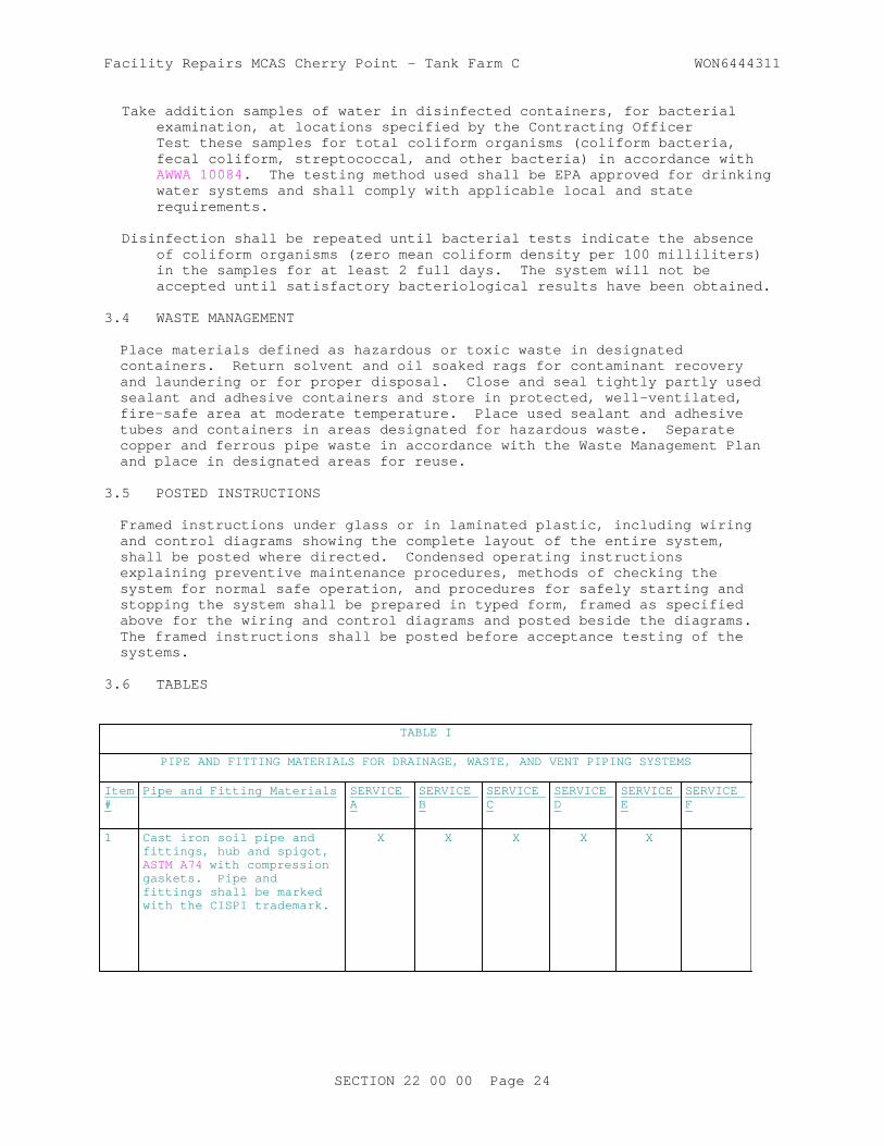
Facility Repairs MCAS Cherry Point - Tank Farm C WON6444311
Take addition samples of water in disinfected containers, for bacterial examination, at locations specified by the Contracting OfficerTest these samples for total coliform organisms (coliform bacteria, fecal coliform, streptococcal, and other bacteria) in accordance with AWWA 10084. The testing method used shall be EPA approved for drinking water systems and shall comply with applicable local and state requirements.
Disinfection shall be repeated until bacterial tests indicate the absence of coliform organisms (zero mean coliform density per 100 milliliters) in the samples for at least 2 full days. The system will not be accepted until satisfactory bacteriological results have been obtained.
3.4 WASTE MANAGEMENT
Place materials defined as hazardous or toxic waste in designated containers. Return solvent and oil soaked rags for contaminant recovery and laundering or for proper disposal. Close and seal tightly partly used sealant and adhesive containers and store in protected, well-ventilated, fire-safe area at moderate temperature. Place used sealant and adhesive tubes and containers in areas designated for hazardous waste. Separate copper and ferrous pipe waste in accordance with the Waste Management Plan and place in designated areas for reuse.
3.5 POSTED INSTRUCTIONS
Framed instructions under glass or in laminated plastic, including wiring and control diagrams showing the complete layout of the entire system, shall be posted where directed. Condensed operating instructions explaining preventive maintenance procedures, methods of checking the system for normal safe operation, and procedures for safely starting and stopping the system shall be prepared in typed form, framed as specified above for the wiring and control diagrams and posted beside the diagrams. The framed instructions shall be posted before acceptance testing of the systems.
3.6 TABLES
TABLE I
PIPE AND FITTING MATERIALS FOR DRAINAGE, WASTE, AND VENT PIPING SYSTEMS
Item #
Pipe and Fitting Materials SERVICE A
SERVICE B
SERVICE C
SERVICE D
SERVICE E
SERVICE F
1 Cast iron soil pipe and fittings, hub and spigot, ASTM A74 with compression gaskets. Pipe and fittings shall be marked with the CISPI trademark.
X X X X X
SECTION 22 00 00 Page 24

Facility Repairs MCAS Cherry Point - Tank Farm C WON6444311
TABLE I
PIPE AND FITTING MATERIALS FOR DRAINAGE, WASTE, AND VENT PIPING SYSTEMS
Item #
Pipe and Fitting Materials SERVICE A
SERVICE B
SERVICE C
SERVICE D
SERVICE E
SERVICE F
2 Cast iron soil pipe and fittings hubless, CISPI 301 and ASTM A888. Pipe and fittings shall be marked with the CISPI trademark.
X X X X
3 Cast iron drainage fittings, threaded, ASME B16.12 for use with Item 10
X X X
4 Cast iron screwed fittings (threaded) ASME B16.4 for use with Item 10
X X
5 Grooved pipe couplings, ferrous and non-ferrous pipe ASTM A536 And ASTM A47/A47M
X X X X
6 Ductile iron grooved joint fittings for ferrous pipe ASTM A536 and ASTM A47/A47M for use with Item 5
X X X X
7 Bronze sand casting grooved joint pressure fittings for non-ferrous pipe ASTM B584, for use with Item 5
X X X X
SECTION 22 00 00 Page 25

Facility Repairs MCAS Cherry Point - Tank Farm C WON6444311
TABLE I
PIPE AND FITTING MATERIALS FOR DRAINAGE, WASTE, AND VENT PIPING SYSTEMS
Item #
Pipe and Fitting Materials SERVICE A
SERVICE B
SERVICE C
SERVICE D
SERVICE E
SERVICE F
8 Wrought copper grooved joint pressure pressure fittings for non-ferrous pipe ASTM B75/B75M C12200, ASTM B152/B152M , C11000, ASME B16.22 ASME B16.22 for use with Item 5
X X
9 Malleable-iron threaded fittings, galvanized ASME B16.3 for use with Item 10
X X
10 Steel pipe, seamless galvanized, ASTM A53/A53M, Type S, Grade B
X X X
11 Seamless red brass pipe, ASTM B43
X X
12 Bronzed flanged fittings, ASME B16.24 for use with Items 11 and 14
X X
13 Cast copper alloy solder joint pressure fittings, ASME B16.18 for use with Item 14
X X
14 Seamless copper pipe, ASTM B42
X
15 Cast bronze threaded fittings, ASME B16.15
X X
16 Copper drainage tube, (DWV), ASTM B306
X* X X* X X
SECTION 22 00 00 Page 26

Facility Repairs MCAS Cherry Point - Tank Farm C WON6444311
TABLE I
PIPE AND FITTING MATERIALS FOR DRAINAGE, WASTE, AND VENT PIPING SYSTEMS
Item #
Pipe and Fitting Materials SERVICE A
SERVICE B
SERVICE C
SERVICE D
SERVICE E
SERVICE F
17 Wrought copper and wrought alloy solder-joint drainage fittings. ASME B16.29
X X X X X
18 Cast copper alloy solder joint drainage fittings, DWV, ASME B16.23
X X X X X
19 Acrylonitrile-Butadiene-Styrene (ABS) plastic drain, waste, and vent pipe and fittings ASTM D2661, ASTM F628
X X X X X X
20 Polyvinyl Chloride plastic drain, waste and vent pipe and fittings, ASTM D2665, ASTM F891, (Sch 40) ASTM F1760
X X X X X X
21 High-silicon content cast iron pipe and fittings (hub and spigot, and mechanical joint), ASTM A518/A518M
X X X
SERVICE: A - Underground Building Soil, Waste and Storm Drain B - Aboveground Soil, Waste, Drain In Buildings C - Underground Vent D - Aboveground Vent E - Interior Rainwater Conductors Aboveground F - Corrosive Waste And Vent Above And Belowground * - Hard Temper
SECTION 22 00 00 Page 27

Facility Repairs MCAS Cherry Point - Tank Farm C WON6444311
TABLE II
PIPE AND FITTING MATERIALS FOR PRESSURE PIPING SYSTEMS
Item # Pipe and Fitting Materials SERVICE A SERVICE B SERVICE C SERVICE D
1 Malleable-iron threaded fittings:
a. Galvanized, ASME B16.3 for use with Item 4a
X X X X
b. Same as "a" but not galvanized for use with Item 4b
X
2 Grooved pipe couplings, ferrous pipe ASTM A536 and ASTM A47/A47M, non-ferrous pipe, ASTM A536 and ASTM A47/A47M
X X X
3 Ductile iron grooved joint fittings for ferrous pipe ASTM A536 and ASTM A47/A47M, for use with Item 2
X X X
4 Steel pipe:
a. Seamless, galvanized, ASTM A53/A53M, Type S, Grade B
X X X X
b. Seamless, black, ASTM A53/A53M, Type S, Grade B
X
5 Seamless red brass pipe, ASTM B43 X X X
6 Bronze flanged fittings, ASME B16.24 for use with Items 5 and 7
X X X
7 Seamless copper pipe, ASTM B42 X X X
8 Seamless copper water tube, ASTM B88, ASTM B88M
X** X** X** X***
9 Cast bronze threaded fittings, ASME B16.15 for use with Items 5 and 7
X X X
SECTION 22 00 00 Page 28

Facility Repairs MCAS Cherry Point - Tank Farm C WON6444311
TABLE II
PIPE AND FITTING MATERIALS FOR PRESSURE PIPING SYSTEMS
Item # Pipe and Fitting Materials SERVICE A SERVICE B SERVICE C SERVICE D
10 Wrought copper and bronze solder-joint pressure fittings, ASME B16.22 for use with Items 5, 7 and 8
X X X X
11 Cast copper alloy solder-joint pressure fittings, ASME B16.18 for use with Item 8
X X X X
12 Bronze and sand castings groovedjoint pressure fittings for non-ferrous pipe ASTM B584, for use with Item 2
X X X
13 Polyethylene (PE) plastic pipe, Schedules 40 and 80, based on outside diameter
X X
14 Polyethylene (PE) plastic pipe (SDR-PR), based on controlled outside diameter, ASTM D3035
X X
15 Polyethylene (PE) plastic pipe (SIDR-PR), based on controlled inside diameter, ASTM D2239
X X
16 Butt fusion polyethylene (PE) plastic pipe fittings, ASTM D3261 for use with Items 14, 15, and 16
X X
17 Socket-type polyethylene fittings for outside diameter-controlled polyethylene pipe, ASTM D2683 for use with Item 15
X X
18 Polyethylene (PE) plastic tubing, ASTM D2737
X X
SECTION 22 00 00 Page 29

Facility Repairs MCAS Cherry Point - Tank Farm C WON6444311
TABLE II
PIPE AND FITTING MATERIALS FOR PRESSURE PIPING SYSTEMS
Item # Pipe and Fitting Materials SERVICE A SERVICE B SERVICE C SERVICE D
19 Chlorinated polyvinyl chloride (CPVC) plastic hot and cold water distribution system, ASTM D2846/D2846M
X X X
20 Chlorinated polyvinyl chloride (CPVC) plastic pipe, Schedule 40 and 80, ASTM F441/F441M
X X X
21 Chlorinated polyvinyl chloride (CPVC) plastic pipe (SDR-PR) ASTM F442/F442M
X X X
22 Threaded chlorinated polyvinyl chloride (chloride CPVC) plastic pipe fittings, Schedule 80, ASTM F437, for use with Items 20, and 21
X X X
23 Socket-type chlorinated polyvinyl chloride (CPVC) plastic pipe fittings, Schedule 40, ASTM F438 for use with Items 20, 21, and 22
X X X
24 Socket-type chlorinated polyvinyl chloride (CPVC) plastic pipe fittings Schedule 80, ASTM F439 for use with Items 20, 21, and 22
X X X
25 Polyvinyl chloride (PVC) plastic pipe, Schedules 40, 80, and 120, ASTM D1785
X X
26 Polyvinyl chloride (PVC) pressure-rated pipe (SDR Series), ASTM D2241
X X
27 Polyvinyl chloride (PVC) plastic pipe fittings, Schedule 40, ASTM D2466
X X
SECTION 22 00 00 Page 30

Facility Repairs MCAS Cherry Point - Tank Farm C WON6444311
TABLE II
PIPE AND FITTING MATERIALS FOR PRESSURE PIPING SYSTEMS
Item # Pipe and Fitting Materials SERVICE A SERVICE B SERVICE C SERVICE D
28 Socket-type polyvinyl chloride (PVC) plastic pipe fittings, schedule 80, ASTM D2467 for use with Items 26 and 27
X X
29 Threaded polyvinyl chloride (PVC) plastic pipe fittings, schedule 80, ASTM D2464
X X
30 Joints for IPS PVC pipe using solvent cement, ASTM D2672
X X
31 Polypropylene (PP) plastic pipe and fittings; ASTM F2389
X X X
32 Steel pipeline flanges, MSS SP-44 X X
33 Fittings: brass or bronze; ASME B16.15 , and ASME B16.18 ASTM B828
X X
34 Carbon steel pipe unions, socket-welding and threaded, MSS SP-83
X X X
35 Malleable-iron threaded pipe unions ASME B16.39
X X
36 Nipples, pipe threaded ASTM A733 X X X
37 Crosslinked Polyethylene (PEX) Plastic Pipe ASTM F877
X X X
SECTION 22 00 00 Page 31

Facility Repairs MCAS Cherry Point - Tank Farm C WON6444311
TABLE II
PIPE AND FITTING MATERIALS FOR PRESSURE PIPING SYSTEMS
Item # Pipe and Fitting Materials SERVICE A SERVICE B SERVICE C SERVICE D
38 Press Fittings: A - Cold Water Service Aboveground B - Hot and Cold Water Distribution 180 degrees F Maximum Aboveground C - Compressed Air Lubricated D - Cold Water Service Belowground Indicated types are minimum wall thicknesses. ** - Type L - Hard *** - Type K - Hard temper with brazed joints only or type K-soft temper without joints in or under floors **** - In or under slab floors only brazed joints
-- End of Section --
SECTION 22 00 00 Page 32

Facility Repairs MCAS Cherry Point - Tank Farm C WON6444311
SECTION 26 00 00.00 20
BASIC ELECTRICAL MATERIALS AND METHODS07/06
PART 1 GENERAL
1.1 REFERENCES
The publications listed below form a part of this specification to the extent referenced. The publications are referred to in the text by the basic designation only.
ASTM INTERNATIONAL (ASTM)
ASTM D709 (2016) Laminated Thermosetting Materials
INSTITUTE OF ELECTRICAL AND ELECTRONICS ENGINEERS (IEEE)
IEEE 100 (2000; Archived) The Authoritative Dictionary of IEEE Standards Terms
IEEE C2 (2012; Errata 1 2012; INT 1-4 2012; Errata 2 2013; INT 5-7 2013; INT 8-10 2014; INT 11 2015; INT 12 2016) National Electrical Safety Code
NATIONAL ELECTRICAL MANUFACTURERS ASSOCIATION (NEMA)
NEMA 250 (2014) Enclosures for Electrical Equipment (1000 Volts Maximum)
NATIONAL FIRE PROTECTION ASSOCIATION (NFPA)
NFPA 70 (2014; AMD 1 2013; Errata 1 2013; AMD 2 2013; Errata 2 2013; AMD 3 2014; Errata 3-4 2014; AMD 4-6 2014) National Electrical Code
1.2 RELATED REQUIREMENTS
This section applies to certain sections of Division 02, EXISTING CONDITIONS , Division 11, EQUIPMENT, Division 13, SPECIAL CONSTRUCTION, and Divisions 22 and 23, PLUMBING and HEATING VENTILATING AND AIR CONDITIONING. This section applies to all sections of Division 26 and 33, ELECTRICAL and UTILITIES, of this project specification unless specified otherwise in the individual sections. This section has been incorporated into, and thus, does not apply to, and is not referenced in the following sections.
Section 26 20 00 INTERIOR DISTRIBUTION SYSTEMSection 27 10 00 BUILDING TELECOMMUNICATIONS CABLING SYSTEMSection 33 71 02 UNDERGROUND ELECTRICAL DISTRIBUTION
1.3 DEFINITIONS
a. Unless otherwise specified or indicated, electrical and electronics terms used in these specifications, and on the drawings, shall be as defined in IEEE 100 .
SECTION 26 00 00.00 20 Page 1

Facility Repairs MCAS Cherry Point - Tank Farm C WON6444311
b. The technical sections referred to herein are those specification sections that describe products, installation procedures, and equipment operations and that refer to this section for detailed description of submittal types.
c. The technical paragraphs referred to herein are those paragraphs in PART 2 - PRODUCTS and PART 3 - EXECUTION of the technical sections that describe products, systems, installation procedures, equipment, and test methods.
1.4 ELECTRICAL CHARACTERISTICS
Electrical characteristics for this project shall be 120/240 volts secondary, single phase, three wire , 60 Hz . Final connections to the power distribution system at the existing transformer shall be made by the Government .
1.5 ADDITIONAL SUBMITTALS INFORMATION
Submittals required in other sections that refer to this section must conform to the following additional requirements as applicable.
1.5.1 Shop Drawings (SD-02)
Include wiring diagrams and installation details of equipment indicating proposed location, layout and arrangement, control panels, accessories, piping, ductwork, and other items that must be shown to ensure a coordinated installation. Wiring diagrams shall identify circuit terminals and indicate the internal wiring for each item of equipment and the interconnection between each item of equipment. Drawings shall indicate adequate clearance for operation, maintenance, and replacement of operating equipment devices.
1.5.2 Product Data (SD-03)
Submittal shall include performance and characteristic curves.
1.6 QUALITY ASSURANCE
1.6.1 Regulatory Requirements
In each of the publications referred to herein, consider the advisory provisions to be mandatory, as though the word, "shall" had been substituted for "should" wherever it appears. Interpret references in these publications to the "authority having jurisdiction," or words of similar meaning, to mean the Contracting Officer. Equipment, materials, installation, and workmanship shall be in accordance with the mandatory and advisory provisions of NFPA 70 unless more stringent requirements are specified or indicated.
1.6.2 Standard Products
Provide materials and equipment that are products of manufacturers regularly engaged in the production of such products which are of equal material, design and workmanship. Products shall have been in satisfactory commercial or industrial use for 2 years prior to bid opening. The 2-year period shall include applications of equipment and materials under similar circumstances and of similar size. The product shall have been on sale on
SECTION 26 00 00.00 20 Page 2

Facility Repairs MCAS Cherry Point - Tank Farm C WON6444311
the commercial market through advertisements, manufacturers' catalogs, or brochures during the 2-year period. Where two or more items of the same class of equipment are required, these items shall be products of a single manufacturer; however, the component parts of the item need not be the products of the same manufacturer unless stated in the technical section.
1.6.2.1 Alternative Qualifications
Products having less than a 2-year field service record will be acceptable if a certified record of satisfactory field operation for not less than 6000 hours, exclusive of the manufacturers' factory or laboratory tests, is furnished.
1.6.2.2 Material and Equipment Manufacturing Date
Products manufactured more than 3 years prior to date of delivery to site shall not be used, unless specified otherwise.
1.7 WARRANTY
The equipment items shall be supported by service organizations which are reasonably convenient to the equipment installation in order to render satisfactory service to the equipment on a regular and emergency basis during the warranty period of the contract.
1.8 POSTED OPERATING INSTRUCTIONS
Provide for each system and principal item of equipment as specified in the technical sections for use by operation and maintenance personnel. The operating instructions shall include the following:
a. Wiring diagrams, control diagrams, and control sequence for each principal system and item of equipment.
b. Start up, proper adjustment, operating, lubrication, and shutdown procedures.
c. Safety precautions.
d. The procedure in the event of equipment failure.
e. Other items of instruction as recommended by the manufacturer of each system or item of equipment.
Print or engrave operating instructions and frame under glass or in approved laminated plastic. Post instructions where directed. For operating instructions exposed to the weather, provide weather-resistant materials or weatherproof enclosures. Operating instructions shall not fade when exposed to sunlight and shall be secured to prevent easy removal or peeling.
1.9 MANUFACTURER'S NAMEPLATE
Each item of equipment shall have a nameplate bearing the manufacturer's name, address, model number, and serial number securely affixed in a conspicuous place; the nameplate of the distributing agent will not be acceptable.
SECTION 26 00 00.00 20 Page 3

Facility Repairs MCAS Cherry Point - Tank Farm C WON6444311
1.10 FIELD FABRICATED NAMEPLATES
ASTM D709. Provide laminated plastic nameplates for each equipment enclosure, relay, switch, and device; as specified in the technical sections or as indicated on the drawings. Each nameplate inscription shall identify the function and, when applicable, the position. Nameplates shall be melamine plastic, 0.125 inch thick, white with black center core. Surface shall be matte finish. Corners shall be square. Accurately align lettering and engrave into the core. Minimum size of nameplates shall be one by 2.5 inches . Lettering shall be a minimum of 0.25 inch high normal block style.
1.11 ELECTRICAL REQUIREMENTS
Electrical installations shall conform to IEEE C2 , NFPA 70 , and requirements specified herein.
1.12 INSTRUCTION TO GOVERNMENT PERSONNEL
Where specified in the technical sections, furnish the services of competent instructors to give full instruction to designated Government personnel in the adjustment, operation, and maintenance of the specified systems and equipment, including pertinent safety requirements as required. Instructors shall be thoroughly familiar with all parts of the installation and shall be trained in operating theory as well as practical operation and maintenance work. Instruction shall be given during the first regular work week after the equipment or system has been accepted and turned over to the Government for regular operation. The number of man-days (8 hours per day) of instruction furnished shall be as specified in the individual section.
PART 2 PRODUCTS
2.1 FACTORY APPLIED FINISH
Electrical equipment shall have factory-applied painting systems which shall, as a minimum, meet the requirements of NEMA 250 corrosion-resistance test.
PART 3 EXECUTION
3.1 FIELD APPLIED PAINTING
Paint electrical equipment as required to match finish of adjacent surfaces or to meet the indicated or specified safety criteria. Painting shall be as specified in the section specifying the associated electrical equipment.
3.2 FIELD FABRICATED NAMEPLATE MOUNTING
Provide number, location, and letter designation of nameplates as indicated. Fasten nameplates to the device with a minimum of two sheet-metal screws or two rivets.
-- End of Section --
SECTION 26 00 00.00 20 Page 4

Facility Repairs MCAS Cherry Point - Tank Farm C WON6444311
SECTION 26 08 00
APPARATUS INSPECTION AND TESTING08/08
PART 1 GENERAL
1.1 REFERENCES
The publications listed below form a part of this specification to the extent referenced. The publications are referred to within the text by the basic designation only.
INTERNATIONAL ELECTRICAL TESTING ASSOCIATION (NETA)
NETA ATS (2013) Standard for Acceptance Testing Specifications for Electrical Power Equipment and Systems
1.2 RELATED REQUIREMENTS
Section 26 00 00.00 20 BASIC ELECTRICAL MATERIALS AND METHODS applies to this section with additions and modifications specified herein.
1.3 SUBMITTALS
Government approval is required for submittals with a "G" designation; submittals not having a "G" designation are for Contractor Quality Control approval. Submit the following in accordance with Section 01 33 00 SUBMITTAL PROCEDURES:
SD-06 Test Reports
Acceptance tests and inspections ; G
SD-07 Certificates
Qualifications of organization, and lead engineering technician; G
Acceptance test and inspections procedure ; G
1.4 QUALITY ASSURANCE
1.4.1 Qualifications
Contractor shall engage the services of a qualified testing organization to provide inspection, testing, calibration, and adjustment of the electrical distribution system and generation equipment listed in paragraph entitled "Acceptance Tests and Inspections" herein. Organization shall be independent of the supplier, manufacturer, and installer of the equipment. The organization shall be a first tier subcontractor. No work required by this section of the specification shall be performed by a second tier subcontractor.
a. Submit name and qualifications of organization. Organization shall have been regularly engaged in the testing of electrical materials, devices, installations, and systems for a minimum of 5 years. The organization shall have a calibration program, and test instruments
SECTION 26 08 00 Page 1

Facility Repairs MCAS Cherry Point - Tank Farm C WON6444311
used shall be calibrated in accordance with NETA ATS.
b. Submit name and qualifications of the lead engineering technician performing the required testing services. Include a list of three comparable jobs performed by the technician with specific names and telephone numbers for reference. Testing, inspection, calibration, and adjustments shall be performed by an engineering technician, certified by NETA or the National Institute for Certification in Engineering Technologies (NICET) with a minimum of 5 years' experience inspecting, testing, and calibrating electrical distribution and generation equipment, systems, and devices.
1.4.2 Acceptance Tests and Inspections Reports
Submit certified copies of inspection reports and test reports. Reports shall include certification of compliance with specified requirements, identify deficiencies, and recommend corrective action when appropriate. Type and neatly bind test reports to form a part of the final record. Submit test reports documenting the results of each test not more than 10 days after test is completed.
1.4.3 Acceptance Test and Inspections Procedure
Submit test procedure reports for each item of equipment to be field tested at least 45 days prior to planned testing date. Do not perform testing until after test procedure has been approved.
PART 2 PRODUCTS
Not used.
PART 3 EXECUTION
3.1 ACCEPTANCE TESTS AND INSPECTIONS
Testing organization shall perform acceptance tests and inspections. Test methods, procedures, and test values shall be performed and evaluated in accordance with NETA ATS, the manufacturer's recommendations, and paragraph entitled "Field Quality Control" of each applicable specification section. Tests identified as optional in NETA ATS are not required unless otherwise specified. Equipment shall be placed in service only after completion of required tests and evaluation of the test results have been completed. Contractor shall supply to the testing organization complete sets of shop drawings, settings of adjustable devices, and other information necessary for an accurate test and inspection of the system prior to the performance of any final testing. Contracting Officer shall be notified at least 14 days in advance of when tests will be conducted by the testing organization. Perform acceptance tests and inspections on applicable equipment and systems specified in the following sections:
a. Section 26 32 13.00 20 SINGLE OPERATION GENERATOR SETS. Functional engine shutdown tests, vibration base-line test, and load bank test shall not be performed by the testing organization. These tests shall be performed by the start-up engineer.
b. Section 33 71 01 OVERHEAD TRANSMISSION AND DISTRIBUTION
c. Section 26 36 23.00 20 AUTOMATIC TRANSFER SWITCHES
SECTION 26 08 00 Page 2

Facility Repairs MCAS Cherry Point - Tank Farm C WON6444311
3.2 SYSTEM ACCEPTANCE
Final acceptance of the system is contingent upon satisfactory completion of acceptance tests and inspections.
3.3 PLACING EQUIPMENT IN SERVICE
A representative of the approved testing organization shall be present when equipment tested by the organization is initially energized and placed in service.
-- End of Section --
SECTION 26 08 00 Page 3


Facility Repairs MCAS Cherry Point - Tank Farm C WON6444311
SECTION 26 20 00
INTERIOR DISTRIBUTION SYSTEM02/14
PART 1 GENERAL
1.1 REFERENCES
The publications listed below form a part of this specification to the extent referenced. The publications are referred to in the text by the basic designation only.
ASTM INTERNATIONAL (ASTM)
ASTM B1 (2013) Standard Specification for Hard-Drawn Copper Wire
ASTM B8 (2011) Standard Specification for Concentric-Lay-Stranded Copper Conductors, Hard, Medium-Hard, or Soft
ASTM D709 (2016) Laminated Thermosetting Materials
INSTITUTE OF ELECTRICAL AND ELECTRONICS ENGINEERS (IEEE)
IEEE 100 (2000; Archived) The Authoritative Dictionary of IEEE Standards Terms
IEEE 81 (2012) Guide for Measuring Earth Resistivity, Ground Impedance, and Earth Surface Potentials of a Ground System
IEEE C2 (2012; Errata 1 2012; INT 1-4 2012; Errata 2 2013; INT 5-7 2013; INT 8-10 2014; INT 11 2015; INT 12 2016) National Electrical Safety Code
NATIONAL ELECTRICAL MANUFACTURERS ASSOCIATION (NEMA)
ANSI C80.1 (2005) American National Standard for Electrical Rigid Steel Conduit (ERSC)
ANSI C80.3 (2015) American National Standard for Electrical Metallic Tubing (EMT)
NEMA 250 (2014) Enclosures for Electrical Equipment (1000 Volts Maximum)
NEMA ICS 6 (1993; R 2011) Enclosures
NEMA KS 1 (2013) Enclosed and Miscellaneous Distribution Equipment Switches (600 V Maximum)
NEMA RN 1 (2005; R 2013) Polyvinyl-Chloride (PVC) Externally Coated Galvanized Rigid Steel Conduit and Intermediate Metal Conduit
SECTION 26 20 00 Page 1

Facility Repairs MCAS Cherry Point - Tank Farm C WON6444311
NEMA TC 2 (2013) Standard for Electrical Polyvinyl Chloride (PVC) Conduit
NEMA TC 3 (2015) Standard for Polyvinyl Chloride (PVC) Fittings for Use With Rigid PVC Conduit and Tubing
NEMA Z535.4 (2011) American National Standard for Product Safety Signs and Labels
NATIONAL FIRE PROTECTION ASSOCIATION (NFPA)
NFPA 70 (2014; AMD 1 2013; Errata 1 2013; AMD 2 2013; Errata 2 2013; AMD 3 2014; Errata 3-4 2014; AMD 4-6 2014) National Electrical Code
NFPA 70E (2015; ERTA 1 2015) Standard for Electrical Safety in the Workplace
NFPA 780 (2014) Standard for the Installation of Lightning Protection Systems
U.S. NATIONAL ARCHIVES AND RECORDS ADMINISTRATION (NARA)
29 CFR 1910.147 Control of Hazardous Energy (Lock Out/Tag Out)
UNDERWRITERS LABORATORIES (UL)
UL 1 (2005; Reprint Jul 2012) Standard for Flexible Metal Conduit
UL 1203 (2013; Reprint Apr 2015) UL Standard for Safety Explosion-Proof and Dust-Ignition-Proof Electrical Equipment for Use in Hazardous (Classified) Locations
UL 1449 (2014; Reprint Mar 2016) Surge Protective Devices
UL 360 (2013; Reprint Jan 2015) Liquid-Tight Flexible Steel Conduit
UL 44 (2014; Reprint Feb 2015) Thermoset-Insulated Wires and Cables
UL 467 (2013) Grounding and Bonding Equipment
UL 486A-486B (2013; Reprint Jan 2016) Wire Connectors
UL 486C (2013; Reprint Jan 2016) Splicing Wire Connectors
UL 489 (2013; Reprint Mar 2014) Molded-Case Circuit Breakers, Molded-Case Switches, and Circuit-Breaker Enclosures
SECTION 26 20 00 Page 2

Facility Repairs MCAS Cherry Point - Tank Farm C WON6444311
UL 50 (2007; Reprint Apr 2012) Enclosures for Electrical Equipment, Non-environmental Considerations
UL 510 (2005; Reprint Jul 2013) Polyvinyl Chloride, Polyethylene and Rubber Insulating Tape
UL 514B (2012; Reprint Nov 2014) Conduit, Tubing and Cable Fittings
UL 6 (2007; Reprint Nov 2014) Electrical Rigid Metal Conduit-Steel
UL 651 (2011; Reprint May 2014) Standard for Schedule 40 and 80 Rigid PVC Conduit and Fittings
UL 67 (2009; Reprint Apr 2015) Standard for Panelboards
UL 674 (2011; Reprint Jul 2013) Electric Motors and Generators for Use in Division 1 Hazardous (Classified) Locations
UL 797 (2007; Reprint Dec 2012) Electrical Metallic Tubing -- Steel
UL 83 (2014) Thermoplastic-Insulated Wires and Cables
UL 869A (2006) Reference Standard for Service Equipment
1.2 DEFINITIONS
Unless otherwise specified or indicated, electrical and electronics terms used in these specifications, and on the drawings, are as defined in IEEE 100 .
1.3 SUBMITTALS
Government approval is required for submittals with a "G" designation; submittals not having a "G" designation are for Contractor Quality Control approval Submit the following in accordance with Section 01 33 00 .
SD-02 Shop Drawings
Panelboards ; G
SD-03 Product Data
Circuit breakers ; G
Emergency Shutdown Push Button ; G
Switches ; G
Surge protective devices ; G
SECTION 26 20 00 Page 3

Facility Repairs MCAS Cherry Point - Tank Farm C WON6444311
Include performance and characteristic curves.
SD-06 Test Reports
600-volt wiring test ; G
Grounding system test ; G
1.4 QUALITY ASSURANCE
1.4.1 Regulatory Requirements
In each of the publications referred to herein, consider the advisory provisions to be mandatory, as though the word, "shall" or "must" had been substituted for "should" wherever it appears. Interpret references in these publications to the "authority having jurisdiction," or words of similar meaning, to mean the Contracting Officer. Provide equipment, materials, installation, and workmanship in accordance with the mandatory and advisory provisions of NFPA 70 unless more stringent requirements are specified or indicated.
1.4.2 Standard Products
Provide materials and equipment that are products of manufacturers regularly engaged in the production of such products which are of equal material, design and workmanship and:
a. Have been in satisfactory commercial or industrial use for 2 years prior to bid opening including applications of equipment and materials under similar circumstances and of similar size.
b. Have been on sale on the commercial market through advertisements, manufacturers' catalogs, or brochures during the 2-year period.
c. Where two or more items of the same class of equipment are required, provide products of a single manufacturer; however, the component parts of the item need not be the products of the same manufacturer unless stated in this section.
1.4.2.1 Alternative Qualifications
Products having less than a 2-year field service record will be acceptable if a certified record of satisfactory field operation for not less than 6000 hours, exclusive of the manufacturers' factory or laboratory tests, is furnished.
1.4.2.2 Material and Equipment Manufacturing Date
Products manufactured more than 3 years prior to date of delivery to site are not acceptable.
1.5 WARRANTY
Provide equipment items supported by service organizations that are reasonably convenient to the equipment installation in order to render satisfactory service to the equipment on a regular and emergency basis during the warranty period of the contract.
SECTION 26 20 00 Page 4

Facility Repairs MCAS Cherry Point - Tank Farm C WON6444311
PART 2 PRODUCTS
2.1 MATERIALS AND EQUIPMENT
As a minimum, meet requirements of UL, where UL standards are established for those items, and requirements of NFPA 70 for all materials, equipment, and devices.
2.2 CONDUIT AND FITTINGS
Conform to the following:
2.2.1 Rigid Metallic Conduit
2.2.1.1 Rigid, Threaded Zinc-Coated Steel Conduit
ANSI C80.1 , UL 6 .
2.2.2 Rigid Nonmetallic Conduit
PVC Type EPC-40 in accordance with NEMA TC 2, UL 651 .
2.2.3 Electrical, Zinc-Coated Steel Metallic Tubing (EMT)
UL 797 , ANSI C80.3 .
2.2.4 Plastic-Coated Rigid Steel
NEMA RN 1, Type 40( 40 mils thick).
2.2.5 Flexible Metal Conduit
UL 1 .
2.2.5.1 Liquid-Tight Flexible Metal Conduit, Steel
UL 360 .
2.2.6 Fittings for Metal Conduit, EMT, and Flexible Metal Conduit
UL 514B . Ferrous fittings: cadmium- or zinc-coated in accordance with UL 514B .
2.2.6.1 Fittings for Rigid Metal Conduit
Threaded-type. Split couplings unacceptable.
2.2.6.2 Fittings for EMT
Steel compression type.
2.2.7 Fittings for Rigid Nonmetallic Conduit
NEMA TC 3 for PVC, and UL 514B .
2.3 CABINETS, JUNCTION BOXES, AND PULL BOXES
Volume greater than 100 cubic inches , UL 50 , hot-dip, zinc-coated, if sheet steel.
SECTION 26 20 00 Page 5

Facility Repairs MCAS Cherry Point - Tank Farm C WON6444311
2.4 WIRES AND CABLES
Provide wires and cables in accordance applicable requirements of NFPA 70 and UL for type of insulation, jacket, and conductor specified or indicated. Do not use wires and cables manufactured more than 12 months prior to date of delivery to site.
2.4.1 Conductors
Provide the following:
a. Conductor sizes and capacities shown are based on copper, unless indicated otherwise.
b. Conductors No. 8 AWG and larger diameter: stranded.
c. Conductors No. 10 AWG and smaller diameter: solid.
d. Conductors for remote control, alarm, and signal circuits, classes 1, 2, and 3: stranded unless specifically indicated otherwise.
e. All conductors: copper.
2.4.1.1 Minimum Conductor Sizes
Provide minimum conductor size in accordance with the following:
a. Branch circuits: No. 12 AWG.
b. Class 1 remote-control and signal circuits: No. 14 AWG.
c. Class 2 low-energy, remote-control and signal circuits: No. 16 AWG.
d. Class 3 low-energy, remote-control, alarm and signal circuits: No. 22 AWG.
2.4.2 Color Coding
Provide color coding for service, feeder, branch, control, and signaling circuit conductors.
2.4.2.1 Ground and Neutral Conductors
Provide color coding of ground and neutral conductors as follows:
a. Grounding conductors: Green.
b. Neutral conductors: White.
c. Exception, where neutrals of more than one system are installed in same raceway or box, other neutrals color coding: white with a different colored (not green) stripe for each.
2.4.2.2 Ungrounded Conductors
Provide color coding of ungrounded conductors in different voltage systems as follows:
SECTION 26 20 00 Page 6

Facility Repairs MCAS Cherry Point - Tank Farm C WON6444311
a. 120/240 volt, single phase: Black and red
2.4.3 Insulation
Unless specified or indicated otherwise or required by NFPA 70 , provide power and lighting wires rated for 600-volts, Type THWN/THHN conforming to UL 83 or Type XHHW conforming to UL 44 , except that grounding wire may be type TW conforming to UL 83 ; remote-control and signal circuits: Type TW or TF, conforming to UL 83 . Where lighting fixtures require 90-degree Centigrade (C) conductors, provide only conductors with 90-degree C insulation or better.
2.4.4 Bonding Conductors
ASTM B1, solid bare copper wire for sizes No. 8 AWG and smaller diameter; ASTM B8, Class B, stranded bare copper wire for sizes No. 6 AWG and larger diameter.
2.5 SPLICES AND TERMINATION COMPONENTS
UL 486A-486B for wire connectors and UL 510 for insulating tapes. Connectors for No. 10 AWG and smaller diameter wires: insulated, pressure-type in accordance with UL 486A-486B or UL 486C (twist-on splicing connector). Provide solderless terminal lugs on stranded conductors.
2.6 SWITCHES
2.6.1 Disconnect Switches
NEMA KS 1. Provide heavy duty-type switches where indicated, where switches are rated higher than 240 volts, and for double-throw switches. Provide horsepower rated for switches serving as the motor-disconnect means. Provide switches in NEMA 4X, enclosure per NEMA ICS 6 .
2.7 EMERGENCY SHUTDOWN PUSH BUTTON
NEMA ICS 1, NEMA ICS 2, and UL 508. Non-illuminated push buttons shall be heavy duty, NEMA 4, round, utilize a 7/8-inch mounting hole, and have the number and type of contacts as indicated on the drawings or elsewhere in the specifications. The emergency shutdown push button shall be red mushroom head, 1.5-inch diameter, momentary contact. Push buttons shall be rated 600 V, 10 amps continuous. Push button enclosure shall be rated NEMA 4X and include a clear weather resistant cover. Legend plates shall be provided with each switch with words as indicated on the drawings.
2.8 PANELBOARDS
Provide panelboards in accordance with the following:
a. UL 67 and UL 50 having a short-circuit current rating as indicated.
b. Panelboards for use as service disconnecting means: additionally conform to UL 869A .
c. Panelboards: circuit breaker-equipped.
d. Designed such that individual breakers can be removed without disturbing adjacent units or without loosening or removing supplemental
SECTION 26 20 00 Page 7

Facility Repairs MCAS Cherry Point - Tank Farm C WON6444311
insulation supplied as means of obtaining clearances as required by UL.
e. "Specific breaker placement" is required in panelboards to match the breaker placement indicated in the panelboard schedule on the drawings.
f. Use of "Subfeed Breakers" is not acceptable unless specifically indicated otherwise.
g. Main breaker: "separately" mounted "above" or "below" branch breakers.
h. Where "space only" is indicated, make provisions for future installation of breakers.
i. Directories: indicate load served by each circuit in panelboard.
j. Directories: indicate source of service to panelboard (e.g., Panel PA served from Panel MDP).
k. Provide new directories for existing panels modified by this project.
l. Type directories and mount in holder behind transparent protective covering.
m. Panelboard nameplates: provided in accordance with paragraph FIELD FABRICATED NAMEPLATES.
2.8.1 Enclosure
Provide panelboard enclosure in accordance with the following:
a. UL 50 .
b. Cabinets mounted outdoors or flush-mounted: hot-dipped galvanized after fabrication.
c. Cabinets: painted in accordance with paragraph PAINTING.
d. Front edges of cabinets: form-flanged or fitted with structural shapes welded or riveted to the sheet steel, for supporting the panelboard front.
e. All cabinets: fabricated such that no part of any surface on the finished cabinet deviates from a true plane by more than 1/8 inch .
f . Holes: provided in the back of indoor surface-mounted cabinets, with outside spacers and inside stiffeners, for mounting the cabinets with a 1/2 inch clear space between the back of the cabinet and the wall surface.
g. Flush doors: mounted on hinges that expose only the hinge roll to view when the door is closed.
h. Each door: fitted with a combined catch and lock, except that doors over 24 inches long provided with a three-point latch having a knob with a T-handle, and a cylinder lock.
i . Keys: two provided with each lock, with all locks keyed alike.
SECTION 26 20 00 Page 8

Facility Repairs MCAS Cherry Point - Tank Farm C WON6444311
j . Finished-head cap screws: provided for mounting the panelboard fronts on the cabinets.
2.8.2 Panelboard Buses
Support bus bars on bases independent of circuit breakers. Design main buses and back pans so that breakers may be changed without machining, drilling, or tapping. Provide isolated neutral bus in each panel for connection of circuit neutral conductors. Provide separate ground bus identified as equipment grounding bus per UL 67 for connecting grounding conductors; bond to steel cabinet.
2.8.3 Circuit Breakers
UL 489 , thermal magnetic-type having a minimum short-circuit current rating equal to the short-circuit current rating of the panelboard in which the circuit breaker will be mounted. Breaker terminals: UL listed as suitable for type of conductor provided. Where indicated on the drawings, provide circuit breakers with shunt trip devices. Series rated circuit breakers and plug-in circuit breakers are unacceptable.
2.8.3.1 Multipole Breakers
Provide common trip-type with single operating handle. Design breaker such that overload in one pole automatically causes all poles to open. Maintain phase sequence throughout each panel so that any two adjacent breaker poles are connected to Lines 1 and 2 , respectively.
2.9 LOCKOUT REQUIREMENTS
Provide disconnecting means capable of being locked out for machines and other equipment to prevent unexpected startup or release of stored energy in accordance with 29 CFR 1910.147 . Comply with requirements of Division 23, "Mechanical" for mechanical isolation of machines and other equipment.
2.10 GROUNDING AND BONDING EQUIPMENT
2.10.1 Ground Rods
UL 467 . Ground rods: copper-clad steel, with minimum diameter of 3/4 inch and minimum length 10 feet .
2.11 HAZARDOUS LOCATIONS
Electrical materials, equipment, and devices for installation in hazardous locations, as defined by NFPA 70 : specifically approved by Underwriters' Laboratories, Inc., or Factory Mutual for particular "Class," "Division," and "Group" of hazardous locations involved. Boundaries and classifications of hazardous locations: as indicated. Equipment in hazardous locations: comply with UL 1203 for electrical equipment and industrial controls and UL 674 for motors.
2.12 MANUFACTURER'S NAMEPLATE
Provide on each item of equipment a nameplate bearing the manufacturer's name, address, model number, and serial number securely affixed in a conspicuous place; the nameplate of the distributing agent will not be acceptable.
SECTION 26 20 00 Page 9

Facility Repairs MCAS Cherry Point - Tank Farm C WON6444311
2.13 FIELD FABRICATED NAMEPLATES
Provide field fabricated nameplates in accordance with the following:
a. ASTM D709.
b. Provide laminated plastic nameplates for each equipment enclosure, relay, switch, and device; as specified or as indicated on the drawings.
c. Each nameplate inscription: identify the function and, when applicable, the position.
d. Nameplates: melamine plastic, 0.125 inch thick, white with black center core.
e. Provide red laminated plastic label with white center core where indicated.
f. Surface: matte finish. Corners: square. Accurately align lettering and engrave into the core.
g. Minimum size of nameplates: one by 2.5 inches .
h. Lettering size and style: a minimum of 0.25 inch high normal block style.
2.14 WARNING SIGNS
Provide warning signs for flash protection in accordance with NFPA 70E and NEMA Z535.4 for panelboards, and equipment panels that are in other than dwelling occupancies and are likely to require examination, adjustment, servicing, or maintenance while energized. Provide field installed signs to warn qualified persons of potential electric arc flash hazards when warning signs are not provided by the manufacturer. Provide marking that is clearly visible to qualified persons before examination, adjustment, servicing, or maintenance of the equipment.
2.15 SURGE PROTECTIVE DEVICES
Provide parallel type surge protective devices (SPD) which comply with UL 1449 at the service entrance panelboards. Provide surge protectors in a NEMA 2 enclosure per NEMA ICS 6 . Use Type 1 or Type 2 SPD and connect on the load side of a dedicated circuit breaker.
Provide the following modes of protection:
FOR SINGLE PHASE AND THREE PHASE WYE CONNECTED SYSTEMS- Phase to phase ( L-L ) Each phase to neutral ( L-N ) Neutral to ground ( N-G ) Phase to ground ( L-G )SPDs at the service entrance: provide with a minimum surge current rating of 80,000 amperes for L-L mode minimum and 40,000 amperes for other modes (L-N, L-G, and N-G).
Provide SPDs. Maximum L-N, L-G, and N-G Voltage Protection Rating: 700V for 120/240V, single phase system
SECTION 26 20 00 Page 10

Facility Repairs MCAS Cherry Point - Tank Farm C WON6444311
Maximum L-L Voltage Protection Rating: 1,200V for 120/240V, single phase system The minimum MCOV (Maximum Continuous Operating Voltage) rating for L-N and L-G modes of operation: 120% of nominal voltage for 240 volts and below.
2.16 FACTORY APPLIED FINISH
Provide factory-applied finish on electrical equipment in accordance with the following:
a. NEMA 250 corrosion-resistance test and the additional requirements as specified herein.
b. Interior and exterior steel surfaces of equipment enclosures: thoroughly cleaned followed by a rust-inhibitive phosphatizing or equivalent treatment prior to painting.
c. Exterior surfaces: free from holes, seams, dents, weld marks, loose scale or other imperfections.
d. Interior surfaces: receive not less than one coat of corrosion-resisting paint in accordance with the manufacturer's standard practice.
e. Exterior surfaces: primed, filled where necessary, and given not less than two coats baked enamel with semigloss finish.
f. Equipment located indoors: ANSI Light Gray, and equipment located outdoors: ANSI Light Gray.
g. Provide manufacturer's coatings for touch-up work and as specified in paragraph FIELD APPLIED PAINTING.
PART 3 EXECUTION
3.1 INSTALLATION
Electrical installations, including weatherproof and hazardous locations and ducts, plenums and other air-handling spaces: conform to requirements of NFPA 70 and IEEE C2 and to requirements specified herein.
3.1.1 Underground Service
Underground service conductors and associated conduit: continuous from service entrance equipment to outdoor power system connection.
3.1.2 Overhead Service
Overhead service conductors into buildings: terminate at service entrance fittings or weatherhead outside building. Overhead service conductors and support bracket for overhead conductors are included in Section 33 71 01 OVERHEAD TRANSMISSION AND DISTRIBUTION.
3.1.3 Hazardous Locations
Perform work in hazardous locations, as defined by NFPA 70 , in strict
SECTION 26 20 00 Page 11

Facility Repairs MCAS Cherry Point - Tank Farm C WON6444311
accordance with NFPA 70 for particular "Class," "Division," and "Group" of hazardous locations involved. Provide conduit and cable seals where required by NFPA 70 . Provide conduit with tapered threads.
3.1.4 Service Entrance Identification
Service entrance disconnect devices, switches, and enclosures: labeled and identified as such.
3.1.4.1 Labels
Wherever work results in service entrance disconnect devices in more than one enclosure, as permitted by NFPA 70 , label each enclosure, new and existing, as one of several enclosures containing service entrance disconnect devices. Label, at minimum: indicate number of service disconnect devices housed by enclosure and indicate total number of enclosures that contain service disconnect devices. Provide laminated plastic labels conforming to paragraph FIELD FABRICATED NAMEPLATES. Use lettering of at least 0.25 inch in height, and engrave on black-on-white matte finish. Service entrance disconnect devices in more than one enclosure: provided only as permitted by NFPA 70 .
3.1.5 Wiring Methods
Provide insulated conductors installed in rigid steel conduit, IMC, rigid nonmetallic conduit, or EMT, except where specifically indicated or specified otherwise or required by NFPA 70 to be installed otherwise. Grounding conductor: separate from electrical system neutral conductor. Provide insulated green equipment grounding conductor for circuit(s) installed in conduit and raceways. Minimum conduit size: 3/4 inch in diameter for low voltage lighting and power circuits.
3.1.5.1 Pull Wire
Install pull wires in empty conduits. Pull wire: plastic having minimum 200-pound force tensile strength. Leave minimum 36 inches of slack at each end of pull wire.
3.1.6 Conduit Installation
Unless indicated otherwise, conceal conduit within finished walls, ceilings, and floors. Keep conduit minimum 6 inches away from parallel runs of flues and steam or hot water pipes. Install conduit parallel with or at right angles to ceilings, walls, and structural members where located above accessible ceilings and where conduit will be visible after completion of project.
3.1.6.1 Restrictions Applicable to EMT
a. Do not install underground.
b. Do not encase in concrete, mortar, grout, or other cementitious materials.
c. Do not use in areas subject to severe physical damage including but not limited to equipment rooms where moving or replacing equipment could physically damage the EMT.
d. Do not use in hazardous areas.
SECTION 26 20 00 Page 12

Facility Repairs MCAS Cherry Point - Tank Farm C WON6444311
e. Do not use outdoors.
3.1.6.2 Restrictions Applicable to Nonmetallic Conduit
a. PVC Schedule 40 and PVC Schedule 80
(1) Do not use in areas where subject to severe physical damage, including but not limited to, mechanical equipment rooms, electrical equipment rooms, hospitals, power plants, missile magazines, and other such areas.
(2) Do not use in hazardous (classified) areas.
( 3) Do not use above grade, except where allowed in this section for rising through floor slab or indicated otherwise.
3.1.6.3 Restrictions Applicable to Flexible Conduit
Use only as specified in paragraph FLEXIBLE CONNECTIONS.
3.1.6.4 Underground Conduit
PVC, Type EPC-40. Convert nonmetallic conduit, other than PVC Schedule 40 or 80, to steel conduit before rising through floor slab.
3.1.6.5 Conduit Through Floor Slabs
Where conduits rise through floor slabs, do not allow curved portion of bends to be visible above finished slab.
3.1.6.6 Stub-Ups
Provide conduits stubbed up through concrete floor for connection to free-standing equipment with adjustable top or coupling threaded inside for plugs, set flush with finished floor. Extend conductors to equipment in rigid steel conduit, except that flexible metal conduit may be used 6 inches above floor. Where no equipment connections are made, install screwdriver-operated threaded flush plugs in conduit end.
3.1.6.7 Conduit Support
Support conduit by pipe straps, wall brackets, threaded rod conduit hangers, or ceiling trapeze. Fasten by toggle bolts on hollow masonry units; by concrete inserts or expansion bolts on concrete or brick; and by machine screws, welded threaded studs, or spring-tension clamps on steel work. Threaded C-clamps may be used on rigid steel conduit only. Do not weld conduits or pipe straps to steel structures. Do not exceed one-fourth proof test load for load applied to fasteners. Provide vibration resistant and shock-resistant fasteners attached to concrete ceiling. Do not cut main reinforcing bars for any holes cut to depth of more than 1 1/2 inches in reinforced concrete beams or to depth of more than 3/4 inch in concrete joints. Fill unused holes. In partitions of light steel construction, use sheet metal screws. In suspended-ceiling construction, run conduit above ceiling. Do not support conduit by ceiling support system. Conduit and box systems: supported independently of both (a) tie wires supporting ceiling grid system, and (b) ceiling grid system into which ceiling panels are placed. Do not share supporting means between electrical raceways and mechanical piping or ducts. Coordinate installationwith above-ceiling
SECTION 26 20 00 Page 13

Facility Repairs MCAS Cherry Point - Tank Farm C WON6444311
mechanical systems to assure maximum accessibility to all systems. Spring-steel fasteners may be used for lighting branch circuit conduit supports in suspended ceilings in dry locations. Where conduit crosses building expansion joints, provide suitable watertight expansion fitting that maintains conduit electrical continuity by bonding jumpers or other means. For conduits greater than 2 1/2 inches inside diameter, provide supports to resist forces of 0.5 times the equipment weight in any direction and 1.5 times the equipment weight in the downward direction.
3.1.6.8 Directional Changes in Conduit Runs
Make changes in direction of runs with symmetrical bends or cast-metal fittings. Make field-made bends and offsets with hickey or conduit-bending machine. Do not install crushed or deformed conduits. Avoid trapped conduits. Prevent plaster, dirt, or trash from lodging in conduits, boxes, fittings, and equipment during construction. Free clogged conduits of obstructions.
3.1.6.9 Locknuts and Bushings
Fasten conduits to sheet metal boxes and cabinets with two locknuts where required by NFPA 70 , where insulated bushings are used, and where bushings cannot be brought into firm contact with the box; otherwise, use at least minimum single locknut and bushing. Provide locknuts with sharp edges for digging into wall of metal enclosures. Install bushings on ends of conduits, and provide insulating type where required by NFPA 70 .
3.1.6.10 Flexible Connections
Provide flexible steel conduit between 3 and 6 feet in length for recessed and semirecessed lighting fixtures; for equipment subject to vibration, noise transmission, or movement; and for motors. Install flexible conduit to allow 20 percent slack. Minimum flexible steel conduit size: 1/2 inch diameter. Provide liquidtight flexible conduit in wet and damp locations for equipment subject to vibration, noise transmission, movement or motors. Provide separate ground conductor across flexible connections.
3.1.7 Boxes, Outlets, and Supports
Provide boxes in wiring and raceway systems wherever required for pulling of wires, making connections, and mounting of devices or fixtures. Boxes for metallic raceways: cast-metal, hub-type when located in wet locations, when surface mounted on outside of exterior surfaces, when surface mounted on interior walls exposed up to 7 feet above floors and walkways, or when installed in hazardous areas and when specifically indicated. Boxes in other locations: sheet stee l . Provide each box with volume required by NFPA 70 for number of conductors enclosed in box. Boxes for mounting lighting fixtures: minimum 4 inches square, or octagonal, except that smaller boxes may be installed as required by fixture configurations, as approved. Boxes for use in masonry-block or tile walls: square-cornered, tile-type, or standard boxes having square-cornered, tile-type covers. Provide gaskets for cast-metal boxes installed in wet locations and boxes installed flush with outside of exterior surfaces. Provide separate boxes for flush or recessed fixtures when required by fixture terminal operating temperature; provide readily removable fixtures for access to boxes unless ceiling access panels are provided. Support boxes and pendants for surface-mounted fixtures on suspended ceilings independently of ceiling supports. Fasten boxes and supports with bolts and expansion shields on concrete or brick, with toggle bolts on hollow masonry units, and with
SECTION 26 20 00 Page 14

Facility Repairs MCAS Cherry Point - Tank Farm C WON6444311
machine screws or welded studs on steel. Threaded studs driven in by powder charge and provided with lockwashers and nuts or nail-type nylon anchors may be used in lieu of wood screws, expansion shields, or machine screws. In open overhead spaces, cast boxes threaded to raceways need not be separately supported except where used for fixture support; support sheet metal boxes directly from building structure or by bar hangers. Where bar hangers are used, attach bar to raceways on opposite sides of box, and support raceway with approved-type fastener maximum 24 inches from box. When penetrating reinforced concrete members, avoid cutting reinforcing steel.
3.1.7.1 Boxes
Boxes for use with raceway systems: minimum 1 1/2 inches deep, except where shallower boxes required by structural conditions are approved. Boxes for other than lighting fixture outlets: minimum 4 inches square, except that 4 by 2 inch boxes may be used where only one raceway enters outlet. Mount outlet boxes flush in finished walls.
3.1.7.2 Pull Boxes
Construct of at least minimum size required by NFPA 70 of code-gauge galvanized sheet steel, except where cast-metal boxes are required in locations specified herein. Provide boxes with screw-fastened covers. Where several feeders pass through common pull box, tag feeders to indicate clearly electrical characteristics, circuit number, and panel designation.
3.1.7.3 Extension Rings
Extension rings are not permitted for new construction. Use only on existing boxes in concealed conduit systems where wall is furred out for new finish.
3.1.8 Mounting Heights
Mount panelboards, enclosed circuit breakers, and disconnecting switches so height of operating handle at its highest position is maximum 78 inches above floor. Mount lighting switches 48 inches above finished floor. Mount receptacles 18 inches above finished floor, unless otherwise indicated. Mount other devices as indicated. Measure mounting heights of wiring devices and outlets in non-hazardous areas to center of device or outlet. Measure mounting heights of receptacle outlet boxes in hazardous area locations to the bottom of the outlet box.
3.1.9 Conductor Identification
Provide conductor identification within each enclosure where tap, splice, or termination is made. For conductors No. 6 AWG and smaller diameter, provide color coding by factory-applied, color-impregnated insulation. For conductors No. 4 AWG and larger diameter, provide color coding by plastic-coated, self-sticking markers; colored nylon cable ties and plates; or heat shrink-type sleeves. Identify control circuit terminations in accordance with manufacturer's recommendations
3.1.10 Splices
Make splices in accessible locations. Make splices in conductors No. 10 AWG and smaller diameter with insulated, pressure-type connector. Make splices in conductors No. 8 AWG and larger diameter with solderless
SECTION 26 20 00 Page 15

Facility Repairs MCAS Cherry Point - Tank Farm C WON6444311
connector, and cover with insulation material equivalent to conductor insulation.
3.1.11 Covers and Device Plates
Install with edges in continuous contact with finished wall surfaces without use of mats or similar devices. Plaster fillings are not permitted. Install plates with alignment tolerance of 1/16 inch . Use of sectional-type device plates are not permitted. Provide gasket for plates installed in wet locations.
3.1.12 Grounding and Bonding
Provide in accordance with NFPA 70 and NFPA 780 . Ground exposed, non-current-carrying metallic parts of electrical equipment, metallic raceway systems, grounding conductor in metallic and nonmetallic raceways, and neutral conductor of wiring systems. Make ground connection at main service equipment, and extend grounding conductor to point of entrance of metallic water service. Make connection to water pipe by suitable ground clamp or lug connection to plugged tee. If flanged pipes are encountered, make connection with lug bolted to street side of flanged connection. Supplement metallic water service grounding system with additional made electrode in compliance with NFPA 70 . Make ground connection to driven ground rods on exterior of building. Interconnect all grounding media in or on the structure to provide a common ground potential. This includes lightning protection, electrical service, telecommunications system grounds, as well as underground metallic piping systems. Use main size lightning conductors for interconnecting these grounding systems to the lightning protection system.
3.1.12.1 Ground Rods
Provide cone pointed ground rods. Measure the resistance to ground using the fall-of-potential method described in IEEE 81 . Do not exceed 25 ohms under normally dry conditions for the maximum resistance of a driven ground. If the resultant resistance exceeds 25 ohms measured not less than 48 hours after rainfall, notify the Contracting Officer who will decide on the number of ground rods to add.
3.1.12.2 Grounding Connections
Make grounding connections which are buried or otherwise normally inaccessible, excepting specifically those connections for which access for periodic testing is required, by exothermic weld or compression connector.
a. Make exothermic welds strictly in accordance with the weld manufacturer's written recommendations. Welds which are "puffed up" or which show convex surfaces indicating improper cleaning are not acceptable. Mechanical connectors are not required at exothermic welds.
b. Make compression connections using a hydraulic compression tool to provide the correct circumferential pressure. Provide tools and dies as recommended by the manufacturer. Use an embossing die code or other standard method to provide visible indication that a connector has been adequately compressed on the ground wire.
3.1.12.3 Resistance
Maximum resistance-to-ground of grounding system: do not exceed 5 ohms
SECTION 26 20 00 Page 16

Facility Repairs MCAS Cherry Point - Tank Farm C WON6444311
under dry conditions. Where resistance obtained exceeds 5 ohms, contact Contracting Officer for further instructions.
3.1.13 Equipment Connections
Provide power wiring for the connection of motors and control equipment under this section of the specification. Except as otherwise specifically noted or specified, automatic control wiring, control devices, and protective devices within the control circuitry are not included in this section of the specifications and are provided under the section specifying the associated equipment.
3.1.14 Repair of Existing Work
Perform repair of existing work, demolition, and modification of existing electrical distribution systems as follows:
3.1.14.1 Workmanship
Lay out work in advance. Exercise care where cutting, channeling, chasing, or drilling of floors, walls, partitions, ceilings, or other surfaces is necessary for proper installation, support, or anchorage of conduit, raceways, or other electrical work. Repair damage to buildings, piping, and equipment using skilled craftsmen of trades involved.
3.1.14.2 Existing Concealed Wiring to be Removed
Disconnect existing concealed wiring to be removed from its source. Remove conductors; cut conduit flush with floor, underside of floor, and through walls; and seal openings.
3.1.14.3 Removal of Existing Electrical Distribution System
Removal of existing electrical distribution system equipment includes equipment's associated wiring, including conductors, cables, exposed conduit, surface metal raceways, boxes, and fittings, back to equipment's power source as indicated.
3.1.14.4 Continuation of Service
Maintain continuity of existing circuits of equipment to remain. Maintain existing circuits of equipment energized. Restore circuits wiring and power which are to remain but were disturbed during demolition back to original condition.
3.1.15 Surge Protective Devices
Connect the surge protective devices in parallel to the power source, keeping the conductors as short and straight as practically possible. Maximum allowed lead length is 3 feet .
3.2 FIELD FABRICATED NAMEPLATE MOUNTING
Provide number, location, and letter designation of nameplates as indicated. Fasten nameplates to the device with a minimum of two sheet-metal screws or two rivets.
SECTION 26 20 00 Page 17

Facility Repairs MCAS Cherry Point - Tank Farm C WON6444311
3.3 WARNING SIGN MOUNTING
Provide the number of signs required to be readable from each accessible side. Space the signs in accordance with NFPA 70E.
3.4 FIELD APPLIED PAINTING
Paint electrical equipment as required to match finish of adjacent surfaces or to meet the indicated or specified safety criteria. Where field painting of enclosures for panelboards, load centers or the like is specified to match adjacent surfaces, to correct damage to the manufacturer's factory applied coatings, or to meet the indicated or specified safety criteria, provide manufacturer's recommended coatings and apply in accordance to manufacturer's instructions.
3.5 FIELD QUALITY CONTROL
Furnish test equipment and personnel and submit written copies of test results. Give Contracting Officer 5 working days notice prior to each test.
3.5.1 Devices Subject to Manual Operation
Operate each device subject to manual operation at least five times, demonstrating satisfactory operation each time.
3.5.2 600-Volt Wiring Test
Test wiring rated 600 volt and less to verify that no short circuits or accidental grounds exist. Perform insulation resistance tests on wiring No. 6 AWG and larger diameter using instrument which applies voltage of approximately 500 volts to provide direct reading of resistance. Minimum resistance: 250,000 ohms.
3.5.3 Grounding System Test
Test grounding system to ensure continuity, and that resistance to ground is not excessive. Test each ground rod for resistance to ground before making connections to rod; tie grounding system together and test for resistance to ground. Make resistance measurements in dry weather, not earlier than 48 hours after rainfall. Submit written results of each test to Contracting Officer, and indicate location of rods as well as resistance and soil conditions at time measurements were made.
-- End of Section --
SECTION 26 20 00 Page 18
Facility Repairs MCAS Cherry Point - Tank Farm C WON6444311
SECTION 26 32 13.00 20
SINGLE OPERATION GENERATOR SETS04/07
PART 1 GENERAL
1.1 REFERENCES
The publications listed below form a part of this specification to the extent referenced. The publications are referred to within the text by the basic designation only.
ASME INTERNATIONAL (ASME)
ASME B16.1 (2015) Gray Iron Pipe Flanges and Flanged Fittings Classes 25, 125, and 250
INSTITUTE OF ELECTRICAL AND ELECTRONICS ENGINEERS (IEEE)
IEEE 115 (2009) Guide for Test Procedures for Synchronous Machines: Part I Acceptance and Performance Testing; Part II Test Procedures and Parameter Determination for Dynamic Analysis
IEEE C2 (2012; Errata 1 2012; INT 1-4 2012; Errata 2 2013; INT 5-7 2013; INT 8-10 2014; INT 11 2015; INT 12 2016) National Electrical Safety Code
IEEE C50.12 (2005; R 2010) Standard for Salient Pole 50 HZ and 60 Hz Synchronous Generators and Generation/Motors for Hydraulic Turbine Applications Rated 5 MVA and above
INTERNATIONAL CODE COUNCIL (ICC)
ICC UBC (1997; Erratas Vol 1, 2 & 3 01/2001; Vol 1 & 2 03/2001; Vol 2 10/2001) Uniform Building Code
INTERNATIONAL ELECTRICAL TESTING ASSOCIATION (NETA)
NETA ATS (2013) Standard for Acceptance Testing Specifications for Electrical Power Equipment and Systems
INTERNATIONAL ORGANIZATION FOR STANDARDIZATION (ISO)
ISO 3046 (1986; Am. 1) Reciprocating Internal Combustion Engines - Performance
ISO 8528 (1993; R 2005) Reciprocating Internal Combustion Engine Driven Alternating Current Generator Sets
SECTION 26 32 13.00 20 Page 1

Facility Repairs MCAS Cherry Point - Tank Farm C WON6444311
NATIONAL ELECTRICAL MANUFACTURERS ASSOCIATION (NEMA)
NEMA C50.10 (1990) Rotating Electrical Machinery - Synchronous Machines
NEMA ICS 6 (1993; R 2011) Enclosures
NEMA MG 1 (2014) Motors and Generators
NATIONAL FIRE PROTECTION ASSOCIATION (NFPA)
NFPA 30 (2015) Flammable and Combustible Liquids Code
NFPA 37 (2015) Standard for the Installation and Use of Stationary Combustion Engines and Gas Turbines
NFPA 70 (2014; AMD 1 2013; Errata 1 2013; AMD 2 2013; Errata 2 2013; AMD 3 2014; Errata 3-4 2014; AMD 4-6 2014) National Electrical Code
U.S. GENERAL SERVICES ADMINISTRATION (GSA)
CID A-A-52557 (Rev A; Notice 1) Fuel Oil, Diesel; for Posts, Camps and Stations
U.S. NATIONAL ARCHIVES AND RECORDS ADMINISTRATION (NARA)
40 CFR 60 Standards of Performance for New Stationary Sources
UNDERWRITERS LABORATORIES (UL)
UL 1236 (2015) Standard for Battery Chargers for Charging Engine-Starter Batteries
UL 142 (2006; Reprint Jul 2013) Steel Aboveground Tanks for Flammable and Combustible Liquids
UL 467 (2013) Grounding and Bonding Equipment
UL 489 (2013; Reprint Mar 2014) Molded-Case Circuit Breakers, Molded-Case Switches, and Circuit-Breaker Enclosures
1.2 RELATED REQUIREMENTS
Section 26 00 00.00 20 BASIC ELECTRICAL MATERIALS AND METHODS, and Section 26 08 00 APPARATUS INSPECTION AND TESTING apply to this section except as modified herein.
1.3 SYSTEM DESCRIPTION
1.3.1 Engine-Generator Set Data
Submit data pertaining to the diesel engine-generator set and to the auxiliary equipment including but not limited to the following:
SECTION 26 32 13.00 20 Page 2

Facility Repairs MCAS Cherry Point - Tank Farm C WON6444311
a. Make of engine.
b. Type or model of engine.
c. Gross bhp rating of engine shall be the total rated power output before deducting power requirements of electric motor-driven equipment or engine driven radiator fan.
d. Net brake power rating of engine shall include deductions for the total power requirements of electric motor-driven or engine-driven accessories as defined in ISO 3046 . Net ratings shall include a deduction in power output for cooling media system power requirements including radiator fans and any other power consuming devices required to provide cooling as specified.
e. Strokes per cycle.
f. Number of cylinders.
g. Bore and stroke, inches .
h. Engine speed, rpm.
i. Piston speed, fpm .
j. kW power rating of engine-generator set as defined in the paragraph entitled "Engine-Generator Set Ratings and Performance."
k. Induction method (naturally aspirated, turbocharged).
l. Intercooler type (air-to-air or jacket water).
m. Governor type, make, and model.
n. Make and model of turbochargers.
1.3.2 Engine-Generator Set Efficiencies
Submit data pertaining to the diesel engine-generator set including but not limited to the following: Loads shall be calculated on basis of rated engine-generator set power.
a. Fuel consumption at 0.80 power factor, gallons per hr .
1. 1/2 load
2. 3/4 load
3. Full load
b. Generator efficiency at 0.80 power factor (percent).
1. 1/2 load
2. 3/4 load
3. Full load
SECTION 26 32 13.00 20 Page 3

Facility Repairs MCAS Cherry Point - Tank Farm C WON6444311
c. Radiator capacity at design conditions.
1. Coolant shall be antifreeze mixture as specified under paragraph entitled "Cooling System."
2. gpm of coolant
3. cfm of air through radiator
4. Btu per hr of heat exchange based on optimum coolant temperature to and from engine.
1.3.3 Diesel Engine Data
Submit data certified by the engine manufacturer including but not limited to the following: Loads shall be calculated on basis of rated engine-generator set power.
a. Approximate exhaust temperature degrees F at full load
b. Weight of exhaust gas at full load lb per hr
c. Weight of intake air at full load lb per hr
d. Total heat rejected at full load Btu per hr
1. To jacket coolant system
2. To fuel oil cooling system
e. Emissions (Lbs/hr)(kg/hr) at full load
1. Total Suspended Particulate
2. Particulate matter with an average aerodynamic diameter of 10 microns (PM-10)
3. Sulfur dioxides
4. Nitrogen Oxides (as N02)
5. Carbon Monoxide
6. Volatile Organic Compounds
f. Visible Emissions (percent opacity) at full load
1.3.4 Generator and Exciter Data
Submit data certified by the generator manufacturer including but not limited to the following:
a. Make and model number of generator
b. kW rating of generator
c. Generator reactances
1. Synchronous reactance, Xd
SECTION 26 32 13.00 20 Page 4

Facility Repairs MCAS Cherry Point - Tank Farm C WON6444311
2. Transient reactance, X'd
3. Subtransient reactance, X"d
4. Negative sequence reactance, X2
5. Zero sequence reactance, Xo
1.3.5 Capacity Calculations for Engine-Generator Set
Calculations shall verify that the engine-generator set power rating is adequate for the load described in the paragraph entitled "Load Profile."
1.3.6 Calculations for Brake Mean Effective Pressure (BMEP)
Calculation shall verify that the diesel engine meets the specified maximum BMEP as follows:
a. kW: Minimum power rating of engine-generator set as defined in the paragraph entitled "Engine-Generator Set Ratings and Performance."
b. rpm: Engine revolutions per minute.
c. cu. in. : Total engine piston displacement in cubic inches .
d. GEN.EFF.: Generator efficiency.
e. x: Multiplication sign.
f. bhp' : Brake horsepower required from diesel engine by generator loaded to full power rating.
g. bhp' : kW/(GEN.EFF. times 0.746) .
h. bhp" : Brake horsepower required by diesel engine driven fan for cooling radiator or motor driven fan for cooling radiator.
i. bhp : bhp' plus bhp" .
j. BMEP psi : (792,000 times bhp)/(rpm times cu. in. ).
1.3.7 Torsional Vibration Stress Analysis Computations
Torsional vibrational stresses in the crankshaft and generator shaft of assembled diesel engine and driven generator shall not exceed 5000 psi when engine is driving generator at rated speed while assembled unit is loaded to rated engine-generator set power. Computations shall be based on a mathematical model of the assembled generator set provided or based on calculations using measured values from tests on a unit identical to the one provided. Calculations based on models of, or measured data from, the unassembled engine and generator will not be acceptable. Calculations shall include:
a. A description of the system relating information pertinent to analysis such as operating speed range and identification plate data.
b. A mass elastic assembly drawing, showing the arrangement of the units
SECTION 26 32 13.00 20 Page 5

Facility Repairs MCAS Cherry Point - Tank Farm C WON6444311
in the generator set and dimensions of shafting, including minimum diameters (or section moduli) of shafting in the system.
c. A labeled line diagram of the mass elastic system indicating values of masses, stiffness, equivalent lengths, and equivalent diameters including basic assumptions and definition of terms.
d. Sample computations showing procedures used to obtain resulting stress values.
e. Computations indicating assembled engine-generator speed of 1800 rpm with assembly loaded to rated generator power and the resulting computed critical torsional stress values in the assembled engine crankshaft and generator shaft.
1.3.8 Capacity Calculations for Batteries
Calculation shall verify that the engine starting battery capacity exceeds dc power requirements.
1.4 SUBMITTALS
Government approval is required for submittals with a "G" designation; submittals not having a "G" designation are for Contractor Quality Control approval. Submit the following in accordance with Section 01 33 00 SUBMITTAL PROCEDURES:
SD-02 Shop Drawings
Engine-Generator set and auxiliary equipment ; G
SD-03 Product Data
Engine-generator set data ; G
Engine-generator set efficiencies ; G
Diesel engine data ; G
Generator and exciter data ; G
Diesel engine-generator set ; G
Auxiliary systems and equipment ; G
Remote alarm annunciator ; G
SD-05 Design Data
Capacity calculations for engine-generator set ; G
Calculations for brake mean effective pressure ; G
Torsional vibration stress analysis computations ; G
Capacity calculations for batteries ; G
SD-06 Test Reports
SECTION 26 32 13.00 20 Page 6

Facility Repairs MCAS Cherry Point - Tank Farm C WON6444311
Acceptance checks and tests ; G
Functional acceptance tests ; G
Functional acceptance test procedure ; G
SD-07 Certificates
Vibration isolation system certification; G
Fuel system certification; G
Start-up engineer qualification resume; G
Instructor's qualification resume; G
SD-09 Manufacturer's Field Reports
Engine tests ; G
Generator tests ; G
Assembled engine-generator set tests ; G
IBC Seismic Certificate of Compliance ; G
SD-10 Operation and Maintenance Data
Diesel engine-generator set , Data Package 4; G
Preliminary assembled operation and maintenance manuals ; G
Submit in accordance with Section 01 78 23 OPERATION AND MAINTENANCE DATA and the paragraph entitled "Assembled Operation and Maintenance Manuals."
SD-11 Closeout Submittals
Posted operating instructions ; G
Training plan ; G
1.5 QUALITY ASSURANCE
1.5.1 Air Permitting
Contractor shall coordinate with Cherry Point Environmental Affairs Department for air permitting at the beginning of the shop drawing submittal phase.
1.5.2 Drawing Requirements
1.5.2.1 Engine-Generator Set and Auxiliary Equipment
Submit drawings pertaining to the engine-generator set and auxiliary equipment, including but not limited to the following:
a. Certified outline, general arrangement (setting plan), and anchor bolt details. Show total weight and center of gravity of assembled
SECTION 26 32 13.00 20 Page 7

Facility Repairs MCAS Cherry Point - Tank Farm C WON6444311
equipment on the steel subbase.
b. Detailed elementary, schematic wiring, and interconnection diagrams of the engine starting system, jacket coolant heating system, engine protective devices, engine alarm devices, engine speed governor system, generator and excitation system, and other integral devices.
c. Detailed elementary, schematic wiring; and interconnection diagrams of the diesel fuel system, starting battery system, engine-generator control panel, generator circuit breaker, and remote alarm annunciator.
d. Dimensional drawings or catalog cuts of exhaust silencers, radiator, diesel fuel day tanks, fuel oil cooler, valves and pumps, intake filters, vibration isolators, and other auxiliary equipment not integral with the engine-generator set.
1.5.3 Vibration Isolation System Certification
Submit certification from the manufacturer that the vibration isolation system will reduce the vibration to the limits specified in the paragraph entitled "Vibration Isolation System."
1.5.4 Fuel System Certification
When the diesel fuel system requires a fuel oil cooler as described in the paragraph entitled "Fuel Oil Cooler," submit certification from the engine manufacturer that the fuel system design is satisfactory.
1.6 IBC Seismic Certificate of Compliance
Generator set shall have an up-to-date IBC Certificate of Compliance meeting the testing, labeling, and certification requirements of the IBC.
1.7 DELIVERY, STORAGE, AND HANDLING
Deliver equipment on pallets or blocking wrapped in heavy-duty plastic, sealed to protect parts and assemblies from moisture and dirt. Plug piping, conduit, exhaust, and air intake openings. Protect and prepare batteries for shipment as recommended by the battery manufacturer. Store auxiliary equipment at the site in covered enclosures, protected from atmospheric moisture, dirt, and ground water.
1.8 SITE CONDITIONS
Protect the components of the engine-generator set, including cooling system components, pumps, fans, and similar auxiliaries when not operating and provide components capable of the specified outputs in the following environment:
a. Site Location: MCAS Cherry Point, Havelock, North Carolina.
b. Site Elevation: 20 feet above mean sea level
c. Ambient Temperatures:
1. Maximum 93 degrees F dry bulb, 81 degrees F wet bulb.
2. Minimum 22 degrees F dry bulb.
SECTION 26 32 13.00 20 Page 8

Facility Repairs MCAS Cherry Point - Tank Farm C WON6444311
d. Design Wind Velocity: 100 mph .
e. Prevailing Wind Direction: SSW.
f. Seismic Zone: Zone 1 as defined by ICC UBC.
1.9 MAINTENANCE
1.9.1 Extra Materials
1.9.1.1 Paint
Furnish one gallon of identical paint used on engine-generator set in manufacturer's sealed container with each engine-generator set.
1.9.1.2 Filters
Furnish four spare replacement elements in their original containers for each filter with each unit.
1.9.2 Posted Operating Instructions
Provide proposed operating instructions for the engine-generator set and auxiliary equipment laminated between matte-surface thermoplastic sheets and suitable for placement adjacent to corresponding equipment. After approval, install operating instructions where directed.
PART 2 PRODUCTS
2.1 DIESEL ENGINE-GENERATOR SET
Provide diesel engine-generator sets consisting of a water cooled diesel engine direct connected to an ac generator with a brushless excitation system and accessories. Equipment and materials shall be the manufacturer's standard products offered in catalogs for commercial or industrial use.
2.1.1 Engine-Generator Set Ratings and Performance
ISO 8528 . Each engine-generator set shall have a power rating of not less than 30 kW at 0.8 power factor and supply 120/ 240 -volt, single -phase, 60-Hz ac output. Coordinate the engine-generator set to ensure an installed rating in the environment described in paragraph entitled "Site Conditions." The power of the engine-generator set is defined as the power output available at the generator terminals excluding the electrical power absorbed by the essential independent auxiliaries. Essential independent auxiliaries are items of equipment which are essential for the continued or repeated operation of the engine which uses power supplied from a source other than the engine.
2.1.1.1 Diesel Engine Capacity
The diesel engine shall meet the specified maximum BMEP requirements at rated speed as calculated in accordance with the paragraph entitled "Calculations for BMEP." The engine capacity shall be based on the following:
a. Engine burning diesel fuel conforming to CID A-A-52557 , Grade DF-2, at an ambient temperature of 85 degrees F .
SECTION 26 32 13.00 20 Page 9

Facility Repairs MCAS Cherry Point - Tank Farm C WON6444311
b. Engine cooled by a radiator fan mechanically driven by the diesel engine or remote with a motor driven fan.
c. Engine cooled by coolant mixture of water and ethylene glycol, 50 percent by volume of each.
Maximum BMEP, psi
Turbocharged and Intercooled
Four-cycle engines 153
Engine speed, rpm: 1800
2.1.1.2 Diesel Engine Emission Limits
Emissions from the operation of the engine-generator set shall not exceed the following limits at full rated load.
a. Total Suspended Particulate 0.14 Kg/Hr
b. Nitrogen Oxides (as NO2) plus Non-Methane Hydrocarbons 2.8 KG/Hr
c. Carbon Monoxide 2.45 Lbs/Hr
2.1.1.3 Performance Class
The voltage and frequency behavior of the generator set shall be in accordance with ISO 8528 operating limit values for performance Class G2.
2.1.1.4 Load Profile
The diesel engine-generator set shall be of adequate capacity necessary for the following load profile:
a. Lighting 3.5 kW
b. HVAC 4.0 kVA,
c. Miscellaneous Small Motors 4.4 kVA, largest 3/4 HP, Full voltage start
d. Other load: 12.9 kW at 1.0 p.f.
2.1.2 Diesel Engines and Accessories
ISO 3046 . Diesel engines shall be four-cycle naturally aspirated, or turbocharged, or turbocharged and intercooled; vertical in-line or vertical Vee type; designed for stationary service. Engines shall be capable of immediate acceleration from rest to normal speed without intermediate idle/warm up period or prelubrication to provide essential electrical power. Two-cycle engines are not acceptable.
2.1.2.1 Subbase Mounting
Mount each engine-generator set on a structural steel subbase sized to support the engine, generator, and necessary accessories, auxiliaries and
SECTION 26 32 13.00 20 Page 10

Facility Repairs MCAS Cherry Point - Tank Farm C WON6444311
control equipment to produce a complete self-contained unit as standard with the manufacturer. Design the structural subbase to properly support the equipment and maintain proper alignment of the engine-generator set in the specified seismic zone. In addition, provide subbase with both lifting rings and jacking pads properly located to facilitate shipping and installation of the unit. Factory align engine and generator on the subbase and securely bolt into place in accordance with the manufacturer's standard practice. Crankshaft shall have rigid coupling for connection to the generator.
2.1.2.2 Assembly
Completely shop assemble each engine-generator set on its structural steel subbase. Paint entire unit with manufacturer's standard paints and colors. After factory tests and before shipping, thoroughly clean and retouch painting as necessary to provide complete protection.
2.1.2.3 Turbocharger
If required by the manufacturer to meet the engine-generator set rating, provide turbine type driven by exhaust gas from engine cylinders, and direct connected to the blower supplying air to the engine intake manifold.
2.1.2.4 Intercooler
Provide manufacturer's standard intercooler for engine size specified.
2.1.2.5 Crankcase Protection
Provide manufacturer's standard method of preventing crankcase explosions and standard method of crankcase ventilation.
2.1.2.6 Engine Lubricating Oil System
Provide each engine with the manufacturer's standard full pressure lubricating oil system arranged to cool the pistons and to distribute oil to moving parts of the engine. Provide oil type and oil filters as recommended by the engine manufacturer.
2.1.2.7 Engine Cooling System
Provide each engine with the manufacturer's standard jacket water pump. Provide a thermostatic control valve in the jacket coolant system for each engine-generator set to maintain a constant jacket coolant temperature to the engine.
2.1.2.8 Engine Fuel System
Provide each engine with the manufacturer's standard fuel system integral with the engine, complete with necessary piping, fittings, and valves for connecting items of equipment which are a part of the system. Provide engine manufacturer's standard hand priming pump. Provide manufacturer's standard simplex filter for each engine, of the throwaway filter element type, consisting of shell filter elements, drains, and necessary connections and fittings.
2.1.2.9 Engine Intake Filter
Provide intake filter assemblies for each engine of the oil bath or dry
SECTION 26 32 13.00 20 Page 11

Facility Repairs MCAS Cherry Point - Tank Farm C WON6444311
type, as standard with the manufacturer. Filters shall be capable of removing a minimum of 92 percent of dirt and abrasive 3 microns and larger from intake air. Size filters to suit engine requirements at 100 percent of rated full load. Design unit for field access for maintenance purposes.
2.1.2.10 Engine Starting System
Starting shall be accomplished using an adequately sized dc starter system with a positive shift solenoid to engage the starter motor and to crank the engine continuously for 60 seconds without overheating.
2.1.2.11 Jacket Coolant Heating System
Provide a factory-installed, 120 volts ac, jacket coolant heating system to ensure rapid starting. Thermostatically control heater at the temperature recommended by engine manufacturer. Include necessary equipment, piping, controls, wiring, and accessories.
2.1.2.12 Engine Protective (Shutdown) Devices
Equip each engine with devices to shut down the engine by shutting off the fuel supply to the engine via a fuel shutoff solenoid. Auxiliary contacts shall be suitable for activating a remote alarm system. Shutdown shall open the associated generator circuit breaker. Provide the following shutdown devices:
a. Overspeed device which operates when engine speed exceeds normal synchronous speed by 18 percent or as recommended by manufacturer. Device shall require manual reset.
b. Pressure switch which operates when lubricating oil pressure to engine drops below a preset value.
c. Temperature switch which operates when jacket coolant temperature exceeds a preset value.
d. Device which operates when the coolant level in the radiator drops below a preset level.
e. Other shutdown devices as recommended by the engine manufacturer.
2.1.2.13 Engine Alarm Devices
Equip each engine with alarm devices. Auxiliary contacts shall be suitable for activating a remote alarm system. Alarm devices shall have factory-fixed set points. Provide the following alarm contact devices:
a. Pressure switch which operates when lubricating oil pressure drops below a preset value.
b. Temperature switch which operates when jacket coolant temperature exceeds a preset value.
c. Temperature switch which operates when jacket coolant temperature is too low.
d. Other alarm devices as recommended by the engine manufacturer.
SECTION 26 32 13.00 20 Page 12

Facility Repairs MCAS Cherry Point - Tank Farm C WON6444311
2.1.2.14 Miscellaneous Engine Accessories
Provide the following engine accessories where the manufacturer's standard design permits:
a. Structural steel subbase and vibration isolators, foundation bolts, nuts, and pipe sleeves.
b. Level jack screws or shims, as required.
c. Rails, chocks, and shims for installation of subbase on the foundation.
d. Removable guard, around fan. Support guard, on engine subbase, to suit manufacturer's standard.
2.1.2.15 Engine Speed Governor System
Provide a forward acting type engine speed governor system. Steady-state frequency band and frequency regulation (droop) shall be in accordance with the operating limit values of the performance class specified in the paragraph entitled "Performance Class."
2.1.3 Generator and Excitation System
2.1.3.1 Generator
Provide salient-pole type, ac, brushless-excited, revolving field, air-cooled, self-ventilated, coupled type, synchronous generator conforming to NEMA MG 1, Part 16, NEMA C50.10 , and IEEE C50.12 . Generator shall be rated for standby duty at 100 percent of the power rating of the engine-generator set as specified in paragraph entitled "Engine-Generator Set Ratings and Performance." Temperature rise of each of the various parts of the generator shall not exceed 130 degrees C as measured by resistance, based on a maximum ambient temperature of 40 degrees C. Winding insulation shall be Class H.
a. Stator: Stator windings shall be provided with VPI insulated coils.
b. Rotor: The rotor shall have connected amortiser windings.
c. Generator Space Heater: Provide 120 volt ac heaters. Heater capacity shall be as recommended by the generator manufacturer to aid in keeping the generator insulation dry.
d. Grounding: Provide non-corrosive steel grounding pads located at two opposite mounting legs.
e. Filters: Provide manufacturer's standard generator cooling air filter assembly.
2.1.3.2 Excitation System
Provide a brushless excitation system consisting of an exciter and rotating rectifier assembly integral with the generator and a voltage regulator. Insulation class for parts integral with the generator shall be as specified in paragraph entitled "Generator." System shall provide a minimum short circuit of 300 percent rated engine-generator set current for at least 10 seconds. Steady state voltage regulation shall be in accordance
SECTION 26 32 13.00 20 Page 13

Facility Repairs MCAS Cherry Point - Tank Farm C WON6444311
with the operating limit values of the performance class specified in the paragraph entitled "Performance Class."
a. Exciter and Rotating Rectifier Assembly: Rectifiers shall be provided with surge voltage protection.
b. Voltage Regulator: Voltage regulator shall be solid state or digital, automatic, three-phase sensing, volts per hertz type regulator. Voltage variation for any 40 degree C change over the operating temperature range shall be less than plus or minus 1.0 percent. Operating temperature shall be minus 40 degree C to plus 70 degree C. Voltage adjust range shall be plus to minus 5.0 percent of nominal. Inherent regulator features shall include overexcitation shutdown.
2.2 ENGINE-GENERATOR SET AUXILIARY SYSTEMS AND EQUIPMENT
Provide auxiliary systems and equipment designed for continuous duty at 100 percent of the power rating of the engine-generator set as specified in the paragraph entitled "Engine-Generator Set Ratings and Performance."
2.2.1 Vibration Isolation System
Install the subbase on vibration isolators that are secured to a suitable concrete foundation. Provide isolators as recommended by the engine-generator set and isolator manufacturers and provide integral or external lateral support to limit lateral movement and overturning moments. The isolation system shall reduce the vibration transmitted to the adjacent floor slab to a maximum of 0.0015 inch total amplitude throughout the frequency range down to 65 Hz.
2.2.2 Exhaust System
Provide exhaust systems for each engine.
2.2.2.1 Exhaust Silencers
A residential class silencer shall be provided for each engine which will reduce the exhaust sound spectrum by the following listed values at a 75 foot radius from the outlet, with generator set loaded to rated capacity and clear weather. Inlet and outlet connections shall be flanged.
Octave Band Center Frequency (Hertz)
Minimum Silencer Attenuation Decibels
63 125 250 500 1000 2000 4000 8000
Residental Class 10 25 32 30 25 25 24 23
2.2.3 Cooling System
Provide the specified cooling water system. Properly size equipment to handle the flow rate and pressure losses of the coolant mixture specified in the paragraph entitled "Diesel Engine Capacity," and at the site elevation specified in the paragraph entitled "Site Conditions."
SECTION 26 32 13.00 20 Page 14

Facility Repairs MCAS Cherry Point - Tank Farm C WON6444311
2.2.3.1 Radiators
Provide for each engine-generator set, as standard with the manufacturer.
a. Design Conditions: Each radiator unit shall have ample capacity to remove not less than the total Btu per hour of heat rejected by its respective engine at 100 percent full-rated load to the jacket water, fuel oil, and lubricating oil system, and intercooler. Radiator capacity shall be rated at optimum temperature of coolant leaving the engine and intercooler as recommended by the engine manufacturer with an ambient dry bulb air temperature outside the enclosure of 110 degrees F maximum, and 24 degrees F minimum at the site elevation specified in the paragraph entitled "Site Conditions," and with the coolant mixture specified in the paragraph entitled "Diesel Engine Capacity." Pressure drop through the radiator shall not exceed 6 psi when circulating the maximum required coolant flow. Radiator air velocity shall be a maximum of 1500 feet per minute .
b. Engine Mounted Radiator Construction: Radiator fan shall direct airflow from the engine outward through the radiator. Fan shall be V-belt driven directly from the engine crankshaft. Cooling section shall have a tube and fin-type core consisting of copper or copper base alloy tubes with nonferrous fins. Select engine-driven fans for quiet vibration-free operation. Make provision for coolant expansion either by self-contained expansion tanks or separately mounted expansion tanks, as standard with the manufacturer. Provide suitable guards for each fan and drive.
c. Coolant solution shall be a mixture of clean water and ethylene glycol, 50 percent by volume each. Provide an anti-freeze solution tester suitable for the mixture.
d. Coolant system shall include a filter for the coolant solution.
2.2.4 Diesel Fuel System
NFPA 30 and NFPA 37 and the requirements herein.
2.2.4.1 Diesel Fuel Piping System
Factory installed piping shall conform to the engine manufacturer's standard. Provide flange connections in accordance with ASME B16.1 Class 125 flanges.
2.2.4.2 Diesel Fuel Day Tank System
Provide 120 volt ac diesel fuel day tank system. Include necessary equipment, piping, controls, wiring, and accessories.
a. Day Tanks: UL 142 . Provide integral in skid double wall (110 percent containment) diesel fuel day tanks with a minimum capacity of 24 hours of engine-generator set operation at full-rated load. Epoxy coat day tanks inside and prime and paint outside. Construct tanks of not less than 3/16 inch steel plate with welded joints and necessary stiffeners on exterior of tank. Provide a braced structural steel framework support. Weld tank top tight and provide an access opening with dustproof, removable 24 inch cover. Provide 4 1/2 inch square inspection port. Provide proper venting of both inner and outer containment.
SECTION 26 32 13.00 20 Page 15

Facility Repairs MCAS Cherry Point - Tank Farm C WON6444311
b. Float Switches: Provide tank-top mounted or external float cage, single-pole, single-throw type designed for use on fuel oil tanks. Arrange high level float switches to close on rise of liquid level, and low level float switches to close on fall of liquid level. Mount float cage units with isolating and drain valves. Contacts shall be suitable for the station battery voltage.
1. Critical low level float switch which shall activate at 5 percent of normal liquid level shall shut engine off.
2. Low-low level float switch which shall activate alarm at 30 percent of normal liquid level.
3. Critical high level float switch which shall activate alarm at 95 percent of normal liquid level.
c. Leak Detector Switch: Actuates when fuel is detected in containment basin, stops fuel transfer pump, and closes the fuel oil solenoid valve.
d. Control Panel: Provide NEMA ICS 6 , Type 3R , enclosed control panel for each day tank. Control panel shall include the following accessories.
1. Power available LED (green).
2. Critical low fuel alarm contacts for shut down of engine.
3. Low-low level fuel alarm LED.
4. Low-low level fuel alarm contacts for remote annunciator.
5. Critical high level fuel alarm LED.
6. Leak detecting alarm LED.
7. Alarm horn.
e. Tank Gages: Provide buoyant force type gages for diesel fuel day tanks with dial indicator not less than 4 inches in size and arranged for top mounting. Calibrate each reading dial or scale for its specific tank to read from empty to full, with intermediate points of 1/4, 1/2, and 3/4.
2.2.4.3 Fuel Oil Cooler
Provide an air cooled fuel oil cooler if the temperature of the fuel returned to the tank from the engine will cause overheating of the tank fuel above the maximum fuel temperature allowed by the engine manufacturer when operating at maximum rated generator power output and low fuel level in the tank. The fuel oil cooler shall be furnished by the engine manufacturer for the application and the installation shall be complete including piping and power requirements.
2.2.4.4 Fuel/Water Separator
Fuel system shall be provided with a fuel/water separator.
SECTION 26 32 13.00 20 Page 16

Facility Repairs MCAS Cherry Point - Tank Farm C WON6444311
2.2.5 Starting Battery System
Provide a 24-volt dc starting battery installation for starting of each engine-generator set utilizing an electric cranking system.
2.2.5.1 Engine Starting Battery
Provide maintenance free, sealed, lead-acid, Absorbant Glass Mat (AGM) diesel engine starting batteries. Batteries shall have sufficient capacity to provide 60 seconds of continuous cranking of the engine in an ambient temperature of 25 degrees F .
2.2.5.2 Starting Battery Charger
UL 1236 . Provide 120 volt ac, enclosed, automatic equalizing, dual-rate, solid-state, constant voltage type battery charger with automatic ac line compensation. Dc output shall be voltage regulated and current limited. Charger shall have two ranges, float and equalize, and shall provide continuous taper charging. The charger shall have a continuous output rating of not less than 10 amperes and shall be sized to recharge the engine starting batteries in a minimum of 8 hours while providing the control power needs of the engine-generator set. Enclosure shall be NEMA ICS 6 , Type 1. The following accessories shall be included:
a. Dc ammeter
b. Dc voltmeter
c. Equalize light
d. Ac on light
e. Low voltage light
f. High voltage light
g. Equalize test button/switch
h. Ac circuit breaker
i. Low dc voltage alarm relay
j. High dc voltage alarm relay
k. Current failure relay
l. Ac power failure relay
2.2.6 Engine-Generator Control Panel
Provide NEMA ICS 6 , Type 3R, enclosed control panel mounted on the engine-generator set with vibration isolators. Provide the following control panel mounted devices and control features.
2.2.6.1 Control Panel Mounted Devices
a. Engine Control Switch (ECS): Provide a three position control switch with "MANUAL START" - "OFF/RESET" - "AUTO START" positions.
SECTION 26 32 13.00 20 Page 17

Facility Repairs MCAS Cherry Point - Tank Farm C WON6444311
b. Emergency Stop Push Button (ESPB): Provide a red, mushroom head, twist-to-reset, maintained contact type push button.
c. Generator Metering: Provide ac metering package that displays ac voltage, current, and frequency of one phase of the generator output simultaneously. Metering package shall include a voltmeter/ammeter phase selector switch to allow viewing of each phase.
d. Generator Voltage Adjust Potentiometer (VAP): Provide a potentiometer, locking screwdriver type, to adjust generator voltage.
e. Engine Instrumentation: Provide instrumentation package that displays the following engine information:
1. Engine oil pressure
2. Engine coolant temperature
3. Engine speed (rpm)
4. Engine running hours
f. Indicating Lamps: Provide LED type indicating lamps and a lamp test switch. Lamps shall indicate the following alarm and shutdown conditions:
1. Low engine lubricating oil pressure alarm
2. Low engine lubricating oil pressure shutdown
3. High engine coolant temperature alarm
4. High engine coolant temperature shutdown
5. Engine overcrank shutdown
6. Engine overspeed shutdown
7. Emergency stop shutdown
8. Starting battery system trouble alarm
9. Day tank low fuel shutdown
10. Low engine coolant temperature alarm
11. Low coolant level shutdown
g. Alarm Horn: Provide an alarm horn and a horn silence switch.
h. Panel Lamp: Provide a panel lamp and lamp "ON-OFF" switch.
2.2.6.2 Crank Cycle/Terminate Relay
Provide crank cycle/terminate relay with adjustable crank/rest periods of 1 to 60 seconds (initially set for 15 seconds) and adjustable total crank time of 30 seconds to 10 minutes (initially set for 75 seconds).
SECTION 26 32 13.00 20 Page 18

Facility Repairs MCAS Cherry Point - Tank Farm C WON6444311
2.2.6.3 Engine Cooldown Relay
Provide cooldown relay with adjustable cool down time of 0 to 30 minutes (initially set at engine manufacturer's recommended time).
2.2.6.4 Non-Volatile Memory
Generator shall be provided with non-volatile memory cabable of storing at least 20 events, and be compatible with RS-485 communications and serial interfacing.
2.2.7 Remote Alarm Annunciator
Provide NEMA ICS 6 , Type 3R , enclosed remote alarm annunciator. The annunciator shall have a lamp test switch and LED type indicating lamps. The annunciator shall give visual and audible warnings for the following operating and alarm conditions:
a. Provide lamps for the following operating conditions:
1. Operating power source, normal or emergency
2. Starting battery system trouble
b. Provide lamps and an audible signal for the following alarm conditions:
1. Low engine lubricating oil pressure
2. Low engine coolant temperature
3. High engine coolant temperature
4. Low fuel
5. Engine overcrank shutdown
6. Engine overspeed shutdown
2.2.7.1 Storage Battery
Provide storage batteries of suitable rating and capacity to supply and maintain power for the remote alarm annunciator for a period of 90 minutes minimum without the voltage applied falling below 87.5 percent of normal. Provide a 120 volt ac automatic battery charger.
2.2.8 Generator Circuit Breaker
UL 489 , molded case, adjustable thermal magnetic trip type circuit breaker. The circuit breaker continuous current rating shall be adequate for the power rating of the engine-generator set and the circuit breaker shall be rated to withstand the short circuit current provided by the generator set. Provide circuit breaker in a NEMA ICS 6 , Type 1 enclosure mounted on the engine-generator set.
2.2.9 Electrical Support Equipment
Furnish with respective pieces of equipment. Motors, controllers, contactors, and disconnects shall conform to Section 26 20 00 INTERIOR DISTRIBUTION SYSTEM. Provide electrical connections under Section 26 20 00
SECTION 26 32 13.00 20 Page 19

Facility Repairs MCAS Cherry Point - Tank Farm C WON6444311
INTERIOR DISTRIBUTION SYSTEM. Provide controllers and contactors with maximum of 120-volt control circuits, and auxiliary contacts for use with controls furnished. When motors and equipment furnished are larger than size indicated, the cost of providing additional electrical service and related work shall be included under this section.
2.2.10 Weatherproof Enclosure
Provide for each engine-generator set and fabricate from zinc coated or phosphatized and shop primed 14 gage minimum sheet steel in accordance with the manufacturer's standard design. Provide a complete, weatherproof enclosure for the engine, generator, and auxiliary systems and equipment. Support exhaust piping and silencer so that the turbocharger is not subjected to exhaust system weight or lateral forces generated in connecting piping that exceed the engine manufacturer's maximum allowed forces and moments. The housing shall have sufficient louvered openings to allow entrance of outside air for engine and generator cooling at full load. Radiator air discharge shall be deflected upward by the enclosure for the purpose of sound attenuation. Sound shall be attenuated to a level of 76 dB at 7 meters (level 2). Design louvered openings to exclude driving rain and snow. Provide properly arranged and sized, hinged panels in the enclosure to allow convenient access to the engine, generator, and control equipment for maintenance and operational procedures. Provide hinged panels with spring type latches which shall hold the panels closed securely and will not allow them to vibrate. Brace the housing internally to prevent excessive vibration when the set is in operation. Enclosure shall have a wind rating of at least 150 miles per hour.
2.3 SPECIAL WRENCHES AND TOOLS
Wrenches and tools specifically designed and required to work on the new equipment, which are not commercially available as standard mechanic's tools, shall be furnished to the Contracting Officer.
2.4 IDENTIFICATION OF EQUIPMENT
Provide plates and tags sized so that inscription is readily legible to operating or maintenance personnel and securely mounted to or attached in proximity of their identified controls or equipment. Lettering shall be normal block lettering, a minimum of 0.25 inch high.
2.4.1 Materials
Construct ID plates and tags of 16 gage minimum thickness bronze or stainless steel sheet metal engraved or stamped with inscription. Construct plates and tags not exposed to the weather or high operational temperature of the diesel engine of laminated plastic, 0.125 inch thick, matte white finish with black center core, with lettering accurately aligned and engraved into the core.
2.4.2 Control Devices and Operation Indicators
Provide ID plates or tags for control devices and operation indicators, including valves, off-on switches, visual alarm annunciators, gages and thermometers, that are required for operation and maintenance of provided mechanical systems. Plates or tags shall be minimum of 0.5 inch high and 2 inches long and shall indicate component system and component function.
SECTION 26 32 13.00 20 Page 20

Facility Repairs MCAS Cherry Point - Tank Farm C WON6444311
2.4.3 Equipment
Provide ID plates of a minimum size of 3 inches high and 5 inches long on provided equipment indicating the following information:
a. Manufacturer's name, address, type and model number, and serial number;
b. Contract number and accepted date;
c. Capacity or size;
d. System in which installed; and
e. System which it controls.
2.5 ASSEMBLED OPERATION AND MAINTENANCE MANUALS
The contents of the assembled operation and maintenance manuals shall include the manufacturer's O&M information required by the paragraph entitled "SD-10, Operation and Maintenance Data" and the manufacturer's O&M information specified in Section 26 36 23.00 20 AUTOMATIC TRANSFER SWITCHES.
a. Manuals shall be in separate books or volumes, assembled and bound securely in durable, hard covered, water resistant binder, and indexed by major assembly and components in sequential order.
b. A table of contents (index) shall be made part of the assembled O&M. The manual shall be assembled in the order noted in table of contents.
c. The cover sheet or binder on each volume of the manuals shall be identified and marked with the words, "Operation and Maintenance Manual."
2.6 SOURCE QUALITY CONTROL
Perform and report on factory tests and inspections prior to shipment. Provide certified copies of manufacturer's test data and results. Test procedures shall conform to ASME, IEEE,and ANSI standards, and to ISO requirements on testing, as appropriate and applicable. The manufacturer performing the tests shall provide equipment, labor, and consumables necessary for tests and measuring and indicating devices shall be certified to be within calibration. Tests shall indicate satisfactory operation and attainment of specified performance. If satisfactory, equipment tested will be given a tentative approval. Equipment shall not be shipped before approval of the factory test reports for the following tests.
2.6.1 Engine Tests
Perform customary commercial factory tests in accordance with ISO 3046 on each engine and associated engine protective device, including, but not limited to the following:
a. Perform dynamometer test at rated power. Record horsepower at rated speed and nominal characteristics such as lubricating oil pressure, jacket water temperature, and ambient temperature.
b. Test and record the values that the low oil pressure alarm and protective shutdown devices actuate prior to assembly on the engine.
SECTION 26 32 13.00 20 Page 21

Facility Repairs MCAS Cherry Point - Tank Farm C WON6444311
c. Test and record values that the high jacket water temperature alarm and protective shutdown devices actuate prior to assembly on the engine.
2.6.2 Generator Tests
Tests shall be performed on the complete factory assembled generator prior to shipment. Conduct tests in accordance with IEEE 115 , NEMA C50.10 , and NEMA MG 1.
2.6.2.1 Routine Tests
Perform the following routine tests on the generators and their exciters:
a. Resistance of armature and field windings
b. Mechanical balance
c. Phases sequence
d. Open circuit saturation curve and phase (voltage) balance test
e. Insulation resistance of armature and field windings
2.6.2.2 Design Tests
Submit the following design tests made on prototype machines that are physically and electrically identical to the generators specified.
a. Temperature rise test
b. Short circuit saturation curve and current balance test
2.6.3 Assembled Engine-Generator Set Tests
Submit the following tests made on prototype machines that are physically and electrically identical to the engine-generator set specified.
2.6.3.1 Initial Stabilization Readings
Operate the engine-generator set and allow the set to stabilize at rated kW at rated power factor, rated voltage, and rated frequency. During this period record instrument readings for output power (kW), terminal voltage, line current, power factor, frequency (rpm) generator (exciter) field voltage and current, lubricating oil pressure, jacket water temperature, and ambient temperature at minimum intervals of 15 minutes. Adjust the load, voltage, and frequency to maintain rated load at rated voltage and frequency. Adjustments to load, voltage, or frequency controls shall be recorded on the data sheet at the time of adjustment. Stabilization shall be considered to have occurred when four consecutive voltage and current recorded readings of the generator (or exciter) field either remain unchanged or have only minor variations about an equilibrium condition with no evident continued increase or decrease in value after the last adjustment to the load, voltage, or frequency has been made.
2.6.3.2 Regulator Range Test
Remove load and record instrument readings (after transients have subsided). Adjust voltage to the maximum attainable value or to a value just prior to actuation of the overvoltage protection device. Apply rated
SECTION 26 32 13.00 20 Page 22

Facility Repairs MCAS Cherry Point - Tank Farm C WON6444311
load and adjust voltage to the minimum attainable value or a value just prior to activation of the undervoltage protection device. The data sheets shall indicate the voltage regulation as a percent of rated voltage and the maximum and minimum voltages attainable. Voltage regulation shall be defined as follows:
Percent Regulation = ((No-Load Voltage) - (Rated-Load Voltage)) x 100 (Rated-Load Voltage)
2.6.3.3 Frequency Range Test
Adjust the engine-generator set frequency for the maximum attainable frequency at rated load. Record instrument readings. Adjust the engine-generator set frequency for the specified minimum attainable frequency at rated load. Record instrument readings. Reduce the load to zero and adjust the engine-generator set frequency for the maximum attainable frequency. Record instrument readings. Adjust the engine-generator set frequency for the minimum attainable frequency. Record instrument readings. The data sheet shall show the maximum and minimum frequencies attained at rated load, and at no load.
2.6.3.4 Transient Response Test
Drop the load to no load and re-apply rated load three times to ensure that the no load and rated load voltage and frequency values are repeatable and that the frequency and voltage regulation is within the limits specified. Record generator terminal voltage and frequency using a high speed strip chart recorder. The data sheet shall show the following results:
a. Frequency
1. Stability bandwidth or deviation in percent of rated frequency.
2. Recovery time.
3. Overshoot and undershoot.
b. Voltage
1. Stability bandwidth or deviation in percent of rated voltage.
2. Recovery time.
3. Overshoot and undershoot.
PART 3 EXECUTION
3.1 INSTALLATION
Installation shall conform to the applicable requirements of IEEE C2 NFPA 30 , NFPA 37 , and NFPA 70 .
3.2 GROUNDING
NFPA 70 and IEEE C2 , except that grounding systems shall have a resistance to solid earth ground not exceeding 5 ohms.
SECTION 26 32 13.00 20 Page 23

Facility Repairs MCAS Cherry Point - Tank Farm C WON6444311
3.2.1 Grounding Electrodes
Provide driven ground rods as specified in Section 33 71 02 UNDERGROUND ELECTRICAL DISTRIBUTION. Connect ground conductors to the upper end of ground rods by exothermic weld or compression connector. Provide compression connectors at equipment end of ground conductors.
3.2.2 Engine-Generator Set Grounding
Provide separate copper grounding conductors and connect them to the ground system as indicated. When work in addition to that indicated or specified is required to obtain the specified ground resistance, the provision of the contract covering "Changes" shall apply.
3.2.3 Connections
Make joints in grounding conductors by exothermic weld or compression connector. Exothermic welds and compression connectors shall be installed as specified in Section 33 71 02 UNDERGROUND ELECTRICAL DISTRIBUTION paragraph regarding "Grounding."
3.2.4 Grounding and Bonding Equipment
UL 467 , except as indicated or specified otherwise.
3.3 START-UP ENGINEER
Provide the services of a qualified factory trained start-up engineer, regularly employed by the engine-generator set manufacturer. The start-up services shall include conducting preliminary operations and functional acceptance tests. The start-up engineer shall be present at the engine generator set installation site, full-time, while preliminary operations and functional acceptance tests are being conducted.
3.4 PREREQUISITES FOR FUNCTIONAL ACCEPTANCE TESTING
Completion of the following requirements is mandatory prior to scheduling functional acceptance tests for the engine-generator set and auxiliary equipment.
3.4.1 Performance of Acceptance Checks and Tests
The acceptance checks and tests shall be accomplished by the testing organization as described in Section 26 08 00 APPARATUS INSPECTION AND TESTING.
3.4.1.1 Generator Sets
Complete as specified in the paragraph entitled "Acceptance Checks and Tests."
3.4.2 Preliminary Operations
The start-up engineer shall conduct manufacturer recommended start-up procedures and tests to verify that the engine-generator set and auxiliary equipment are ready for functional acceptance tests. Give the Contracting Officer 15 days' advance notice that preliminary operations will be conducted. After preliminary operation has been successfully conducted, the start-up engineer will notify the Contracting Officer in writing
SECTION 26 32 13.00 20 Page 24

Facility Repairs MCAS Cherry Point - Tank Farm C WON6444311
stating the engine-generator set and auxiliary equipment are ready for functional acceptance tests.
3.4.3 Preliminary Assembled Operation and Maintenance Manuals
Preliminary assembled operation and maintenance manuals shall have been submitted to and approved by the Contracting Officer. Manuals shall be prepared as specified in the paragraph entitled "Assembled Operation and Maintenance Manuals."
3.4.4 Functional Acceptance Test Procedure
Test procedure shall be prepared by the start-up engineer specifically for the engine-generator set and auxiliary equipment. The test agenda shall cover the requirements specified in the paragraph entitled "Functional Acceptance Tests." The test procedure shall indicate in detail how tests are to be conducted. A statement of the tests that are to be performed without indicating how the tests are to be performed is not acceptable. Indicate what work is planned on each workday and identify the calendar dates of the planned workdays. Specify what additional technical support personnel is needed such as factory representatives for major equipment. Specify on which testing workday each technical support personnel is needed. Data recording forms to be used to document test results are to be submitted with the proposed test procedure. A list of test equipment and instruments shall also be included in the test procedure.
3.4.5 Test Equipment
Test equipment and instruments shall be on hand prior to scheduling field tests or, subject to Contracting Officer approval, evidence shall be provided to show that arrangements have been made to have the necessary equipment and instruments on site prior to field testing.
3.5 FIELD QUALITY CONTROL
Give Contracting Officer 30 days notice of dates and times scheduled for tests which require the presence of the Contracting Officer. The Contracting Officer will coordinate with the using activity and schedule a time that will eliminate or minimize interruptions and interference with the activity operations. The Contractor shall be responsible for costs associated with conducting tests outside of normal working hours and with incorporating special arrangements and procedures, including temporary power conditions. The Contractor shall provide labor, equipment, diesel fuel, test load, and consumables required for the specified tests. The test load shall be a cataloged product. Calibration of measuring devices and indicating devices shall be certified. Refer to Section 26 00 00.00 20 BASIC ELECTRICAL MATERIALS AND METHODS, for requirements for a cataloged product. Perform the following field tests.
3.5.1 Acceptance Checks and Tests
Perform in accordance with the manufacturer's recommendations, and include the following visual and mechanical inspections and electrical tests, performed in accordance with NETA ATS.
3.5.1.1 Circuit Breakers - Low Voltage Insulated Case/Molded Case
a. Visual and mechanical inspection
SECTION 26 32 13.00 20 Page 25

Facility Repairs MCAS Cherry Point - Tank Farm C WON6444311
1. Compare nameplate data with specifications and approved shop drawings.
2. Inspect circuit breaker for correct mounting.
3. Operate circuit breaker to ensure smooth operation.
4. Inspect case for cracks or other defects.
5. Verify tightness of accessible bolted connections and cable connections by calibrated torque-wrench method. Thermographic survey is not required.
6. Inspect mechanism contacts and arc chutes in unsealed units.
b. Electrical Tests
1. Perform contact-resistance tests.
2. Perform insulation-resistance tests.
3. Adjust Breaker(s) for final settings in accordance with engine-generator set manufacturer's requirements.
3.5.1.2 Current Transformers
a. Visual and Mechanical Inspection
1. Compare equipment nameplate data with specifications and approved shop drawings.
2. Inspect physical and mechanical condition.
3. Verify correct connection.
4. Verify that adequate clearances exist between primary and secondary circuit.
5. Verify tightness of accessible bolted electrical connections by calibrated torque-wrench method. Thermographic survey is not required.
6. Verify that all required grounding and shorting connections provide good contact.
b. Electrical Tests
1. Perform insulation-resistance tests.
2. Perform polarity tests.
3. Perform ratio-verification tests.
3.5.1.3 Metering and Instrumentation
a. Visual and Mechanical Inspection
1. Compare equipment nameplate data with specifications and approved shop drawings.
SECTION 26 32 13.00 20 Page 26

Facility Repairs MCAS Cherry Point - Tank Farm C WON6444311
2. Inspect physical and mechanical condition.
3. Verify tightness of electrical connections.
b. Electrical Tests
1. Determine accuracy of meters at 25, 50, 75, and 100 percent of full scale.
2. Calibrate watthour meters according to manufacturer's published data.
3. Verify all instrument multipliers.
4. Electrically confirm that current transformer secondary circuits are intact.
3.5.1.4 Battery Systems
a. Visual and mechanical inspection
1. Compare equipment nameplate data with specifications and approved shop drawings.
2. Inspect physical and mechanical condition.
3. Verify tightness of accessible bolted electrical connections by calibrated torque-wrench method. Thermographic survey is not required.
4. Measure electrolyte specific gravity and temperature and visually check fill level.
5. Verify adequacy of battery support racks, mounting, anchorage, and clearances.
b. Electrical tests
1. Set charger float and equalizing voltage levels.
2. Verify all charger functions and alarms.
3. Measure each cell voltage and total battery voltage with charger energized and in float mode of operation.
4. Perform a capacity load test.
3.5.1.5 Engine-Generator Set
a. Visual and mechanical inspection
1. Compare equipment nameplate data with specifications and approved shop drawings.
2. Inspect physical and mechanical condition.
3. Inspect for correct anchorage and grounding.
SECTION 26 32 13.00 20 Page 27

Facility Repairs MCAS Cherry Point - Tank Farm C WON6444311
b. Electrical and mechanical tests
1. Perform an insulation-resistance test on generator winding with respect to ground. Calculate polarization index.
2. Perform phase rotation test to determine compatibility with load requirements.
3.5.1.6 Grounding System
a. Visual and mechanical inspection
1. Inspect ground system for compliance with contract plans and specifications.
b. Electrical tests
1. Perform ground-impedance measurements utilizing the fall-of-potential method. On systems consisting of interconnected ground rods, perform tests after interconnections are complete. On systems consisting of a single ground rod perform tests before any wire is connected. Take measurements in normally dry weather, not less than 48 hours after rainfall. Use a portable ground testing megger in accordance with manufacturer's instructions to test each ground or group of grounds. The instrument shall be equipped with a meter reading directly in ohms or fractions thereof to indicate the ground value of the ground rod or grounding systems under test.
3.5.2 Functional Acceptance Tests
The tests shall be performed by the start-up engineer. Upon successful test completion, the start-up engineer shall provide the Contracting Officer with a written test report within 15 calendar days showing the tests performed and the results of each test. The report shall include the completed approved test data forms and certification from the start-up engineer that the test results fall within the manufacturer's recommended limits and meet the specified requirements performance. The report shall be dated and signed by the start-up engineer, and submitted for approval by the Contracting Officer. The Contracting Officer will witness final acceptance tests. Testing shall include but not be limited to:
a. Verify proper functioning of each engine protective shutdown device and pre-shutdown alarm device. Testing of the devices shall be accomplished by simulating device actuation and observing proper alarm and engine shutdown operation.
b. Verify proper functioning of the engine overspeed trip device. Testing of the overspeed trip device shall be accomplished by raising the speed of the engine-generator set until an overspeed trip is experienced.
c. Verify proper functioning of the crank cycle/terminate relay. Testing of the relay shall be accomplished by engaging the starter motor with the engine being prevented from running. Observe the complete crank/rest cycle as described in the paragraph entitled "Crank Cycle/Terminate Relay."
d. Verify proper functioning of the following automatic and manual operations. Testing shall include but not be limited to:
SECTION 26 32 13.00 20 Page 28

Facility Repairs MCAS Cherry Point - Tank Farm C WON6444311
1. Loss of Utility: Initiate a normal power failure with connected test load of rated kW at 1.0 power factor. Record time delay on start, cranking time until engine starts and runs, time to come up to operating speed, voltage and frequency overshoot, and time to achieve steady state conditions with all switches transferred to emergency position.
2. Return of Utility: Return normal power and record time delay on retransfer for each automatic transfer switch, and time delay on engine cooldown and shutdown.
3. Manual starting
4. Emergency stop
e. Operate the engine-generator set at rated current (amperes) until the jacket water temperature stabilizes. Stabilization will be considered to have occurred when three consecutive temperature readings remain unchanged. Continue to operate the generator set for an additional 2 hours. Record instrument readings for terminal voltage, line current, frequency (Hz), engine speed rpm, lubricating oil pressure, jacket water temperature, and ambient temperature at 5 minute intervals for first 15 minutes and at 15 minute intervals thereafter.
3.5.3 Emissions Tests
Provide on site testing by a certified testing organization of each engine-generator set. Testing shall be in accordance with an EPA approved method, 40 CFR 60 , (Appendix, Method 7, 7A, 7B, 7C, 7D or 7E). Emissions at rated full load shall be within the limits specified in the paragraph entitled "Diesel Engine Emissions Limits."
3.6 DEMONSTRATION
Upon completion of the work and at a time approved by the Contracting Officer, the Contractor shall provide instructions by a qualified instructor to the Government personnel in the proper operation and maintenance of the equipment. Ten Government personnel shall receive training comparable to the equipment manufacturer's factory training. The duration of instruction shall be for not less than one 8 hour working day for instruction of operating personnel and not less than one 8 hour working day for instruction of maintenance personnel.
3.6.1 Instructor's Qualification Resume
Instructors shall be regular employees of the engine-generator set manufacturer. The instruction personnel provided to satisfy the requirements above shall be factory certified by the related equipment manufacturer to provide instruction services. Submit the name and qualification resume of instructor to the Contracting Officer for approval.
3.6.2 Training Plan
Submit training plan 30 calendar days prior to training sessions. Training plan shall include scheduling, content, outline, and training material (handouts). Content shall include but not limited to the following:
SECTION 26 32 13.00 20 Page 29

Facility Repairs MCAS Cherry Point - Tank Farm C WON6444311
3.6.2.1 Operating Personnel Training
This instruction includes operating the engine-generator set, auxiliary equipment including automatic transfer switches in all modes, and the use of all functions and features specified.
3.6.2.2 Maintenance Personnel Training
Shall include mechanical, hydraulic, electrical, and electronic instructions for the engine-generator set and auxiliary equipment including automatic transfer switches.
a. Mechanical Training: Shall include at least the following:
1. A review of mechanical diagrams and drawings.
2. Component location and functions.
3. Troubleshooting procedures and techniques.
4. Repair procedures.
5. Assembly/disassembly procedures.
6. Adjustments (how, when, and where).
7. Preventive maintenance procedures.
8. Review of flow diagram.
9. Valve locations and function.
10. Valve and hydraulic equipment adjustment and maintenance procedures.
11. Hydraulic system maintenance and servicing.
12. Lubrication points, type, and recommended procedures and frequency.
b. Electrical and Electronic Maintenance Training: Shall include at least the following:
1. A review of electrical and electronic systems including wiring diagrams and drawings.
2. Troubleshooting procedures for the machine and control systems.
3. Electrical and electronic equipment servicing and care.
4. Use of diagnostics to locate the causes of malfunction.
5. Procedures for adjustments (locating components, adjustments to be made, values to be measured, and equipment required for making adjustments).
6. Maintenance and troubleshooting procedures for microprocessor or
SECTION 26 32 13.00 20 Page 30

Facility Repairs MCAS Cherry Point - Tank Farm C WON6444311
minicomputer where applicable.
7. Circuit board repair procedures where applicable (with schematics provided).
8. Use of diagnostic tapes.
9. Recommended maintenance servicing and repair for motors, switches, relays, solenoids, and other auxiliary equipment and devices.
-- End of Section --
SECTION 26 32 13.00 20 Page 31

Facility Repairs MCAS Cherry Point - Tank Farm C WON6444311
SECTION 26 36 23.00 20
AUTOMATIC TRANSFER SWITCHES04/06
PART 1 GENERAL
1.1 REFERENCES
The publications listed below form a part of this specification to the extent referenced. The publications are referred to within the text by the basic designation only.
INTERNATIONAL ELECTRICAL TESTING ASSOCIATION (NETA)
NETA ATS (2013) Standard for Acceptance Testing Specifications for Electrical Power Equipment and Systems
NATIONAL FIRE PROTECTION ASSOCIATION (NFPA)
NFPA 70 (2014; AMD 1 2013; Errata 1 2013; AMD 2 2013; Errata 2 2013; AMD 3 2014; Errata 3-4 2014; AMD 4-6 2014) National Electrical Code
UNDERWRITERS LABORATORIES (UL)
UL 1008 (2014) Transfer Switch Equipment
UL 508 (1999; Reprint Oct 2013) Industrial Control Equipment
1.2 RELATED REQUIREMENTS
Section 26 00 00.00 20 BASIC ELECTRICAL MATERIALS AND METHODS, and Section 26 08 00 APPARATUS INSPECTION AND TESTING, apply to this section, with the additions and modifications specified herein.
1.3 SUBMITTALS
Government approval is required for submittals with a "G" designation; submittals not having a "G" designation are for Contractor Quality Control approval. Submit the following in accordance with Section 01 33 00 SUBMITTAL PROCEDURES:
SD-02 Shop Drawings
Automatic Transfer Switch Drawings ; G
SD-03 Product Data
Automatic Transfer Switches ; G
SD-06 Test Reports
Acceptance Checks and Tests ; G
SECTION 26 36 23.00 20 Page 1

Facility Repairs MCAS Cherry Point - Tank Farm C WON6444311
Functional Acceptance Tests ; G
SD-07 Certificates
Proof of Listing ; G
SD-10 Operation and Maintenance Data
Automatic Transfer Switches , Data Package 5; G
Submit in accordance with Section 01 78 23 OPERATION AND MAINTENANCE DATA.
1.4 QUALITY ASSURANCE
1.4.1 Proof of Listing
Submit proof of listing by UL 1008 .
1.4.2 Automatic Transfer Switch Drawings
Drawings shall include outline, arrangement, and detail drawings. Detail drawings shall include manufacturer's name and catalog number, electrical ratings, total system transfer statement, reduced normal supply voltage at which transfer to the alternate supply is initiated, transfer delay times, short-circuit current rating, wiring diagram, description of interconnections, testing instructions, acceptable conductor type for terminals, tightening torque for each wire connector, and other required UL 1008 markings.
PART 2 PRODUCTS
2.1 AUTOMATIC TRANSFER SWITCHES
Provide three -pole, automatic transfer switches for use in emergency systems in accordance with UL 1008 . Each automatic transfer switch shall be rated for total system transfer and have the current and voltage ratings as indicated. The rating of the switch shall be adequate for withstanding the effects of the indicated RMS symmetrical fault current when protected by the indicated overcurrent device without contact welding. The switch operating mechanism shall be electrically operated from the source to which it is transferring, shall have quick-make, quick-break, load break contacts, and shall be mechanically held in both positions. Non-fire pump service transfer switches shall have manual operating means provided for maintenance and servicing accessible only by opening the enclosure. The manual operating means shall affect the opening and closing of the switch contacts at the same rate of speed as that caused by the automatic operation of the switch. The switch enclosure shall comply with UL 508 , NEMA Type 3R, and shall be equipped with an equipment ground lug.
2.1.1 Automatic Transfer Switch Controls
2.1.1.1 Controls for Utility-Generator Automatic Transfer Switch
Provide all necessary controls to start the generator set upon loss of the normal (utility) source, transfer the load to the generator set upon reaching rated voltage and frequency, re-transfer the load when the normal (utility) source returns, and stop the generator set.
SECTION 26 36 23.00 20 Page 2

Facility Repairs MCAS Cherry Point - Tank Farm C WON6444311
The switch shall include the following control features.
a. Single -phase normal source voltage sensing circuit with adjustable dropout, 75-93 percent of nominal, and pickup, 85-100 percent of nominal.
b. Engine starting control contacts with adjustable commit-to-start delay circuit, 0.5-6.0 seconds.
c. Voltage/frequency sensing circuit, set for 80 percent of nominal, for enabling load transfer to emergency source.
d. Transfer to emergency source time delay for transfer switches as indicated, adjustable 0-5 minutes.
e. Re-transfer to normal source time delay, adjustable 1-30 minutes.
f. Programmable exerciser to allow automatic starting of the generator set and subsequent load transfer. Exercise periods shall be selectable for 1 to 24 hours per day for 0 to 7 days a week.
g. Adjustable time delay transition or in-phase monitor feature for indicated transfer switches to allow safe transfer of highly inductive loads between two non-synchronized sources.
2.1.2 Front Panel Devices
Provide devices mounted on cabinet front consisting of:
a. Mode selector switch with the following positions and associated functions;
1. TEST - Simulates loss of normal/preferred source system operation.
2. NORMAL - Transfers system to normal/preferred source bypassing re-transfer time delay.
b. Lamps for indicating connected source and normal/preferred source is available.
c. Auxiliary contacts for indicating connected source and normal/preferred source available.
PART 3 EXECUTION
3.1 INSTALLATION
Installation shall conform to the requirements of NFPA 70 and manufacturer's recommendation.
3.2 PREREQUISITES FOR FUNCTIONAL ACCEPTANCE TESTING
Completion of the following requirements is mandatory prior to scheduling functional acceptance tests for the automatic transfer switch.
3.2.1 Performance of Acceptance Checks and tests
Complete as specified in paragraph entitled "Acceptance Checks and Tests". The Acceptance Checks and Tests shall be accomplished by the Testing
SECTION 26 36 23.00 20 Page 3

Facility Repairs MCAS Cherry Point - Tank Farm C WON6444311
organization as described in Section 26 08 00 APPARATUS INSPECTION AND TESTING.
3.2.2 Manufacturers O&M Information
The manufacturers O&M information required by the paragraph entitled "SD-10 Operation and Maintenance Data", shall have been submitted to and approved by the Contracting Officer.
3.2.3 Test Equipment
All test equipment and instruments shall be on hand prior to scheduling field tests, or subject to Contracting Officer's approval, evidence shall be provided to show that arrangements have been made to have the necessary equipment and instruments on site prior to field testing.
3.3 FIELD QUALITY CONTROL
Give Contracting Officer 15 days notice of dates and times scheduled for tests which require the presence of the Contracting Officer. The Contracting Officer will coordinate with the using activity and schedule a time that will eliminate or minimize interruptions and interference with the activity operations. The contractor shall be responsible for costs associated with conducting tests outside of normal working hours and with incorporating special arrangements and procedures, including temporary power conditions. The contractor shall provide labor, equipment, apparatus, including test load, and consumables required for the specified tests. Calibration of all measuring devices and indicating devices shall be certified. The test load shall be a cataloged product in accordance with Section 26 00 00.00 20 BASIC ELECTRICAL MATERIALS AND METHODS. Perform the following field tests in accordance with the manufacturer's recommendations and include the following visual and mechanical inspections and electrical tests, performed in accordance with NETA ATS.
3.3.1 Automatic Transfer Switch Acceptance Checks and Tests
a. Visual and Mechanical Inspection
1. Compare equipment nameplate data with specifications and approved shop drawings.
2. Inspect physical and mechanical condition.
3. Confirm correct application of manufacturer's recommended lubricants.
4. Verify that manual transfer warnings are attached and visible.
5. Verify tightness of all control connections.
6. Verify tightness of accessible bolted connections by calibrated torque-wrench method. Thermographic survey is not required.
7. Perform manual transfer operation.
8. Verify positive mechanical interlocking between normal and alternate sources.
b. Electrical Tests
SECTION 26 36 23.00 20 Page 4

Facility Repairs MCAS Cherry Point - Tank Farm C WON6444311
1. Measure contact-resistance.
2. Perform insulation-resistance on each pole, phase-to-phase and phase-to-ground with switch closed, and across each open pole for one minute. Perform tests in both source positions.
3. Verify settings and operations of control devices.
4. Calibrate and set all relays and timers.
3.3.2 Functional Acceptance Tests
Functional Acceptance Tests shall be coordinated with Section 26 32 13.00 20 SINGLE OPERATION GENERATOR SETS and shall include simulating power failure and demonstrating the following operations for each automatic transfer switch. Contractor shall show by demonstration in service that the automatic transfer switches are in good operating condition, and function not less than five times.
a. Perform automatic transfer tests:
1. Simulate loss of normal/preferred power.
2. Return to normal/preferred power.
3. Simulate loss of emergency power.
4. Simulate all forms of single-phase conditions.
b. Verify correct operation and timing of the following functions:
1. Normal source voltage-sensing relays.
2. Engine start sequence.
3. Time delay upon transfer.
4. Alternate source voltage-sensing relays.
5. Automatic transfer operation.
6. Interlocks and limit switch function.
7. Time delay and retransfer upon normal power restoration.
-- End of Section --
SECTION 26 36 23.00 20 Page 5


Facility Repairs MCAS Cherry Point - Tank Farm C WON6444311
SECTION 26 41 00
LIGHTNING PROTECTION SYSTEM11/13
PART 1 GENERAL
1.1 REFERENCES
The publications listed below form a part of this specification to the extent referenced. The publications are referred to within the text by the basic designation only.
NATIONAL FIRE PROTECTION ASSOCIATION (NFPA)
NFPA 70 (2014; AMD 1 2013; Errata 1 2013; AMD 2 2013; Errata 2 2013; AMD 3 2014; Errata 3-4 2014; AMD 4-6 2014) National Electrical Code
NFPA 780 (2014) Standard for the Installation of Lightning Protection Systems
UNDERWRITERS LABORATORIES (UL)
UL 96 (2005; Reprint Mar 2015) Standard for Lightning Protection Components
1.2 RELATED REQUIREMENTS
1.2.1 Verification of Dimensions
Confirm all details of work, verify all dimensions in field, and advise Contracting Officer of any discrepancy before performing work. Obtain prior approval of Contracting Officer before making any departures from the design.
1.2.2 System Requirements
Provide a system furnished under this specification consisting of the latest UL Listed products of a manufacturer regularly engaged in production of lightning protection system components. Comply with NFPA 70 , NFPA 780 , and UL 96 .
1.2.3 Lightning Protection System Installers Documentation
Provide documentation showing that the installer is certified with a commercial third-party inspection company whose sole work is lightning protection, or is a UL Listed Lightning Protection Installer. In either case, the documentation must show that they have completed and passed the requirements for certification or listing, and have a minimum of 2 years documented experience installing lightning protection systems for DoD projects of similar scope and complexity.
1.3 SUBMITTALS
Government approval is required for submittals with a "G" designation; submittals not having a "G" designation are for Contractor Quality Control
SECTION 26 41 00 Page 1

Facility Repairs MCAS Cherry Point - Tank Farm C WON6444311
approval. Submit the following in accordance with Section 01 33 00 SUBMITTAL PROCEDURES:
SD-02 Shop Drawings
Overall lightning protection system ; G
Each major component ; G
SD-06 Test Reports
Lightning Protection and Grounding System Test Plan ; G
Lightning Protection and Grounding System Test ; G
SD-07 Certificates
Lightning Protection System Installers Documentation ; G
Component UL Listed and Labeled ; G
Lightning protection system inspection certificate ; G
Roof manufacturer's warranty ; G
1.4 QUALITY ASSURANCE
In each standard referred to herein, consider the advisory provisions to be mandatory, as though the word "shall" or "must" has been substituted for "should" wherever it appears. Interpret references in these standards to "authority having jurisdiction," or words of similar meaning, to mean Contracting Officer.
1.4.1 Installation Drawings
1.4.1.1 Overall System Drawing
Submit installation shop drawing for the overall lightning protection system . Include on the drawings the physical layout of the equipment (plan view and elevations), mounting details, relationship to other parts of the work, and wiring diagrams.
1.4.1.2 Major Components
Submit detail drawings for each major component including manufacturer's descriptive and technical literature, catalog cuts, and installation instructions.
1.4.2 Component UL Listed and Labeled
Submit proof of compliance that components are UL Listed and Labeled. Listing alone in UL Electrical Constructn , which is the UL Electrical Construction Directory, is not acceptable evidence. In lieu of Listed and Labeled, submit written certificate from an approved, nationally recognized testing organization equipped to perform such services, stating that items have been tested and conform to requirements and testing methods of Underwriters Laboratories.
SECTION 26 41 00 Page 2

Facility Repairs MCAS Cherry Point - Tank Farm C WON6444311
1.4.3 Lightning Protection and Grounding System Test Plan
Provide a lightning protection and grounding system test plan. Detail both the visual inspection and electrical testing of the system and components in the test plan. Identify (number) the system test points/locations along with a listing or description of the item to be tested and the type of test to be conducted. As a minimum, include a sketch of the facility and surrounding lightning protection system as part of the specific test plan for each structure. Include the requirements specified in paragraph, "Testing of Integral Lightning Protection System" in the test plan.
1.4.4 Lightning Protection System Inspection Certificate
Provide certification from a commercial third-party inspection company whose sole work is lightning protection, stating that the lightning protection system complies with NFPA 780 . Third party inspection company cannot be the system installer or the system designer. Alternatively, provide a UL Lightning Protection Inspection Master Label Certificate for each facility indicating compliance to NFPA 780 .
Inspection must cover every connection, air terminal, conductor, fastener, accessible grounding point and other components of the lightning protection system to ensure 100% system compliance. This includes witnessing the tests for the resistance measurements for ground rods with test wells, and for continuity measurements for bonds. It also includes verification of proper surge protective devices for power, data and telecommunication systems. Random sampling or partial inspection of a facility is not acceptable.
1.5 SITE CONDITIONS
Confirm all details of work, verify all dimensions in field, and advise Contracting Officer of any discrepancy before performing work. Obtain prior approval of Contracting Officer before changing the design.
PART 2 PRODUCTS
2.1 MATERIALS
Do not use a combination of materials that forms an electrolytic couple of such nature that corrosion is accelerated in the presence of moisture unless moisture is permanently excluded from the junction of such metals. Where unusual conditions exist which would cause corrosion of conductors, provide conductors with protective coatings, such as tin or lead, or oversize conductors. Where a mechanical hazard is involved, increase conductor size to compensate for the hazard or protect conductors. When metallic conduit or tubing is provided, electrically bond conductor to conduit or tubing at the upper and lower ends by clamp type connectors or welds (including exothermic). All lightning protection components, such as bonding plates, air terminals, air terminal supports and braces, chimney bands, clips, connector fittings, and fasteners are to comply with the requirements of UL 96 classes as applicable.
2.1.1 Main and Bonding Conductors
NFPA 780 and UL 96 Class I, Class II, or Class II modified materials as applicable.
SECTION 26 41 00 Page 3

Facility Repairs MCAS Cherry Point - Tank Farm C WON6444311
2.2 COMPONENTS
2.2.1 Air Terminals
Provide solid air terminals with a blunt tip. Tubular air terminals are not permitted. Support air terminals more than 24 inches in length by suitable brace, supported at not less than one-half the height of the terminal.
2.2.2 Connections and Terminations
Provide connectors for splicing conductors that conform to UL 96 , class as applicable. Conductor connections can be made by clamps or welds (including exothermic). Provide style and size connectors required for the installation.
2.2.3 Connector Fittings
Provide connector fittings for "end-to-end", "Tee", or "Y" splices that conform to NFPA 780 and UL 96 .
PART 3 EXECUTION
3.1 INTEGRAL SYSTEM
Provide a lightning protection system that meets the requirements of NFPA 780 . Lightning protection system consists of air terminals, roof conductors, down conductors, ground connections, grounding electrodes and ground ring electrode conductor. Expose conductors on the structures except where conductors are required to be in protective sleeves. Bond secondary conductors with grounded metallic parts within the building. Make interconnections within side-flash distances at or below the level of the grounded metallic parts.
3.1.1 Roof-Mounted Components
Coordinate with the roofing manufacturer and provide certification that the roof manufacturer's warranty is not violated by the installation methods for air terminals and roof conductors.
3.1.1.1 Air Terminals
Use a standing seam base for installation of air terminals on a standing seam metal roof that does not produce any roof penetrations.
3.1.1.2 Roof Conductors
Use a standing seam base for installation of roof conductors on a standing seam metal roof that does not produce any roof penetrations.
3.1.2 Down Conductors
Protect exposed down conductors from physical damage as required by NFPA 780 . Use Schedule 80 PVC to protect down conductors. Paint the Schedule 80 PVC to match the surrounding surface with paint that is approved for use on PVC.
3.1.3 Ground Connections
Attach each down conductor to ground ing electrode conductors as indicated .
SECTION 26 41 00 Page 4

Facility Repairs MCAS Cherry Point - Tank Farm C WON6444311
Accessible connections above ground level can be accomplished by mechanical clamping.
3.2 APPLICATIONS
3.2.1 Metallic Roof s
Bond metal roof sections together which are insulated from each other so that they are electrically continuous, having a surface contact of at least 3 square inches .
3.3 RESTORATION
Restore, to original condition, the areas disturbed by trenching, storing of dirt, cable laying, and other work. Overfill to accommodate for settling. Include necessary topsoil, fertilizing, liming, seeding, sodding, sprigging or mulching in any restoration. Maintain disturbed surfaces and replacements until final acceptance.
3.4 FIELD QUALITY CONTROL
3.4.1 Lightning Protection and Grounding System Test
Test the lightning protection and grounding system to ensure continuity is not in excess of 1 ohm and that resistance to ground is not in excess of 15 ohms. Provide documentation for the measured values at each test point. Test the ground rod for resistance to ground before making connections to the rod. Tie the grounding system together and test for resistance to ground. Make resistance measurements in dry weather, not earlier than 48 hours after rainfall. Include in the written report: locations of test points, measured values for continuity and ground resistances, and soil conditions at the time that measurements were made. Submit results of each test to the Contracting Officer.
-- End of Section --
SECTION 26 41 00 Page 5


Facility Repairs MCAS Cherry Point - Tank Farm C WON6444311
SECTION 27 10 00
BUILDING TELECOMMUNICATIONS CABLING SYSTEM08/11
PART 1 GENERAL
1.1 REFERENCES
The publications listed below form a part of this specification to the extent referenced. The publications are referred to within the text by the basic designation only.
ASTM INTERNATIONAL (ASTM)
ASTM D709 (2016) Standard Specification for Laminated Thermosetting Materials
INSTITUTE OF ELECTRICAL AND ELECTRONICS ENGINEERS (IEEE)
IEEE 100 (2000; Archived) The Authoritative Dictionary of IEEE Standards Terms
INSULATED CABLE ENGINEERS ASSOCIATION (ICEA)
ICEA S-83-596 (2016) Indoor Optical Fiber Cables
NATIONAL ELECTRICAL CONTRACTORS ASSOCIATION (NECA)
NECA/BICSI 568 (2006) Standard for Installing Building Telecommunications Cabling
NATIONAL FIRE PROTECTION ASSOCIATION (NFPA)
NFPA 70 (2017) National Electrical Code
TELECOMMUNICATIONS INDUSTRY ASSOCIATION (TIA)
TIA-1152 (2009) Requirements for Field Test Instruments and Measurements for Balanced Twisted-Pair Cabling
TIA-455-21 (1988a; R 2012) FOTP-21 - Mating Durability of Fiber Optic Interconnecting Devices
TIA-526-7 (2015a) OFSTP-7 Measurement of Optical Power Loss of Installed Single-Mode Fiber Cable Plant
TIA-568-C.0 (2009; Add 1 2010; Add 2 2012) Generic Telecommunications Cabling for Customer Premises
TIA-568-C.1 (2009; Add 2 2011; Add 1 2012) Commercial Building Telecommunications Cabling Standard
SECTION 27 10 00 Page 1

Facility Repairs MCAS Cherry Point - Tank Farm C WON6444311
TIA-568-C.2 (2009; Errata 2010; Add 2 2014; Add 1 2016) Balanced Twisted-Pair Telecommunications Cabling and Components Standards
TIA-568-C.3 (2008; Add 1 2011) Optical Fiber Cabling Components Standard
TIA-569 (2015d) Commercial Building Standard for Telecommunications Pathways and Spaces
TIA-606 (2012b; Add 1 2015) Administration Standard for the Telecommunications Infrastructure
TIA-607 (2011b) Generic Telecommunications Bonding and Grounding (Earthing) for Customer Premises
TIA/EIA-598 (2014d) Optical Fiber Cable Color Coding
TIA/EIA-604-10 (2002a) FOCIS 10 Fiber Optic Connector Intermateability Standard - Type LC
UNDERWRITERS LABORATORIES (UL)
UL 467 (2013) Grounding and Bonding Equipment
UL 969 (1995; Reprint Sep 2014) Standard for Marking and Labeling Systems
1.2 RELATED REQUIREMENTS
Section 26 20 00 INTERIOR DISTRIBUTION SYSTEM applies to this section with additions and modifications specified herein.
1.3 DEFINITIONS
Unless otherwise specified or indicated, electrical and electronics terms used in this specification shall be as defined in TIA-568-C.1 , TIA-568-C.2 , TIA-568-C.3 , TIA-569 , TIA-606 and IEEE 100 and herein.
1.3.1 Campus Distributor (CD)
A distributor from which the campus backbone cabling emanates. (International expression for main cross-connect (MC).)
1.3.2 Building Distributor (BD)
A distributor in which the building backbone cables terminate and at which connections to the campus backbone cables may be made. (International expression for intermediate cross-connect (IC).)
1.3.3 Floor Distributor (FD)
A distributor used to connect horizontal cable and cabling subsystems or equipment. (International expression for horizontal cross-connect (HC).)
SECTION 27 10 00 Page 2

Facility Repairs MCAS Cherry Point - Tank Farm C WON6444311
1.3.4 Telecommunications Room (TR)
An enclosed space for housing telecommunications equipment, cable, terminations, and cross-connects. The room is the recognized cross-connect between the backbone cable and the horizontal cabling.
1.3.5 Entrance Facility (EF) (Telecommunications)
An entrance to the building for both private and public network service cables (including wireless) including the entrance point at the building wall and continuing to the equipment room.
1.3.6 Equipment Room (ER) (Telecommunications)
An environmentally controlled centralized space for telecommunications equipment that serves the occupants of a building. Equipment housed therein is considered distinct from a telecommunications room because of the nature of its complexity.
1.3.7 Open Cable
Cabling that is not run in a raceway as defined by NFPA 70 . This refers to cabling that is "open" to the space in which the cable has been installed and is therefore exposed to the environmental conditions associated with that space.
1.3.8 Pathway
A physical infrastructure utilized for the placement and routing of telecommunications cable.
1.4 SYSTEM DESCRIPTION
The building telecommunications cabling and pathway system shall include permanently installed backbone and horizontal cabling, horizontal and backbone pathways, service entrance facilities, work area pathways, telecommunications outlet assemblies, conduit, raceway, and hardware for splicing, terminating, and interconnecting cabling necessary to transport telephone and data (including LAN) between equipment items in a building. The horizontal system shall be wired in a star topology from the telecommunications work area to the floor distributor or campus distributor at the center or hub of the star. The backbone cabling and pathway system includes intrabuilding and interbuilding interconnecting cabling, pathway, and terminal hardware. The intrabuilding backbone provides connectivity from the floor distributors to the building distributors or to the campus distributor and from the building distributors to the campus distributor as required. The backbone system shall be wired in a star topology with the campus distributor at the center or hub of the star. Provide telecommunications pathway systems referenced herein as specified in Section 26 20 00 INTERIOR DISTRIBUTION SYSTEM and 33 71 02 UNDERGROUND ELECTRICAL DISTRIBUTION. The telecommunications contractor must coordinate with the NMCI/COSC/NGEN contractor concerning access to and configuration of telecommunications spaces. The telecommunications contractor may be required to coordinate work effort within the telecommunications spaces with the NMCI/COSC/NGEN contractor.
1.5 SUBMITTALS
Government approval is required for submittals with a "G" designation;
SECTION 27 10 00 Page 3

Facility Repairs MCAS Cherry Point - Tank Farm C WON6444311
submittals not having a "G" designation are for Contractor Quality Control approval. Submit the following in accordance with Section 01 33 00 SUBMITTAL PROCEDURES:
SD-03 Product Data
Telecommunications cabling (horizontal); G
Telecommunications outlet/connector assemblies ; G
SD-06 Test Reports
Telecommunications cabling testing ; G
SD-07 Certificates
Telecommunications Contractor Qualifications; G
Manufacturer Qualifications ; G
Test plan ; G
SD-09 Manufacturer's Field Reports
Factory reel tests ; G
SD-10 Operation and Maintenance Data
Telecommunications cabling and pathway system Data Package 5; G 1.6 QUALITY ASSURANCE
1.6.1 Telecommunications Qualifications
Work under this section shall be performed by and the equipment shall be provided by the approved telecommunications contractor and key personnel. Qualifications shall be provided for: the telecommunications system contractor, the telecommunications system installer, and the supervisor (if different from the installer). A minimum of 30 days prior to installation, submit documentation of the experience of the telecommunications contractor and of the key personnel.
1.6.1.1 Telecommunications Contractor
The telecommunications contractor shall be a firm which is regularly and professionally engaged in the business of the applications, installation, and testing of the specified telecommunications systems and equipment. The telecommunications contractor shall demonstrate experience in providing successful telecommunications systems within the past 3 years of similar scope and size. Submit documentation for a minimum of three and a maximum of five successful telecommunication system installations for the telecommunications contractor.
1.6.1.2 Minimum Manufacturer Qualifications
Cabling, equipment and hardware manufacturers shall have a minimum of 3 years experience in the manufacturing, assembly, and factory testing of components which comply with TIA-568-C.1 , TIA-568-C.2 and TIA-568-C.3 .
SECTION 27 10 00 Page 4

Facility Repairs MCAS Cherry Point - Tank Farm C WON6444311
1.6.2 Test Plan
Provide a complete and detailed test plan for the telecommunications cabling system including a complete list of test equipment for the components and accessories for each cable type specified, 60 days prior to the proposed test date. Include procedures for certification, validation, and testing.
1.6.3 Regulatory Requirements
In each of the publications referred to herein, consider the advisory provisions to be mandatory, as though the word, "shall" had been substituted for "should" wherever it appears. Interpret references in these publications to the "authority having jurisdiction," or words of similar meaning, to mean the Contracting Officer. Equipment, materials, installation, and workmanship shall be in accordance with the mandatory and advisory provisions of NFPA 70 unless more stringent requirements are specified or indicated.
1.6.4 Standard Products
Provide materials and equipment that are products of manufacturers regularly engaged in the production of such products which are of equal material, design and workmanship. Products shall have been in satisfactory commercial or industrial use for 2 years prior to bid opening. The 2-year period shall include applications of equipment and materials under similar circumstances and of similar size. The product shall have been on sale on the commercial market through advertisements, manufacturers' catalogs, or brochures during the 2-year period. Where two or more items of the same class of equipment are required, these items shall be products of a single manufacturer; however, the component parts of the item need not be the products of the same manufacturer unless stated in this section.
1.6.4.1 Alternative Qualifications
Products having less than a 2-year field service record will be acceptable if a certified record of satisfactory field operation for not less than 6000 hours, exclusive of the manufacturers' factory or laboratory tests, is furnished.
1.6.4.2 Material and Equipment Manufacturing Date
Products manufactured more than 1 year prior to date of delivery to site shall not be used, unless specified otherwise.
1.7 DELIVERY AND STORAGE
Provide protection from weather, moisture, extreme heat and cold, dirt, dust, and other contaminants for telecommunications cabling and equipment placed in storage.
1.8 ENVIRONMENTAL REQUIREMENTS
Connecting hardware shall be rated for operation under ambient conditions of 32 to 140 degrees F and in the range of 0 to 95 percent relative humidity, noncondensing.
SECTION 27 10 00 Page 5

Facility Repairs MCAS Cherry Point - Tank Farm C WON6444311
1.9 WARRANTY
The equipment items shall be supported by service organizations which are reasonably convenient to the equipment installation in order to render satisfactory service to the equipment on a regular and emergency basis during the warranty period of the contract.
1.10 MAINTENANCE
1.10.1 Operation and Maintenance Manuals
Commercial off the shelf manuals shall be furnished for operation, installation, configuration, and maintenance of products provided as a part of the telecommunications cabling and pathway system , Data Package 5. Submit operations and maintenance data in accordance with Section 01 78 23 OPERATION AND MAINTENANCE DATA and as specified herein. Ensure that these drawings and documents depict the as-built configuration.
PART 2 PRODUCTS
2.1 COMPONENTS
Components shall be UL or third party certified. Where equipment or materials are specified to conform to industry and technical society reference standards of the organizations, submit proof of such compliance. The label or listing by the specified organization will be acceptable evidence of compliance. In lieu of the label or listing, submit a certificate from an independent testing organization, competent to perform testing, and approved by the Contracting Officer. The certificate shall state that the item has been tested in accordance with the specified organization's test methods and that the item complies with the specified organization's reference standard. Provide a complete system of telecommunications cabling and pathway components using star topology. Provide support structures and pathways, complete with outlets, cables, connecting hardware and telecommunications cabinets/racks. Cabling and interconnecting hardware and components for telecommunications systems shall be UL listed or third party independent testing laboratory certified, and shall comply with NFPA 70 and conform to the requirements specified herein.
2.2 TELECOMMUNICATIONS PATHWAY
Provide telecommunications pathways in accordance with TIA-569 and as specified in Section 26 20 00 INTERIOR DISTRIBUTION SYSTEM.
2.3 TELECOMMUNICATIONS CABLING
Cabling shall be UL listed for the application and shall comply with TIA-568-C.0 , TIA-568-C.1 , TIA-568-C.2 , TIA-568-C.3 and NFPA 70 . Provide a labeling system for cabling as required by TIA-606 and UL 969 . Ship cable on reels or in boxes bearing manufacture date for optical fiber cables in accordance with ICEA S-83-596 for all cable used on this project. Cabling manufactured more than 12 months prior to date of installation shall not be used.
2.3.1 Horizontal Cabling
Provide horizontal cable in compliance with NFPA 70 and performance
SECTION 27 10 00 Page 6

Facility Repairs MCAS Cherry Point - Tank Farm C WON6444311
characteristics in accordance with TIA-568-C.1 .
2.3.1.1 Horizontal Optical Fiber
Provide optical fiber horizontal cable in accordance with ICEA S-83-596 and TIA-568-C.3 . Cable shall be tight buffered, single-mode, 8/125-um diameter, OS1. Cable shall be imprinted with manufacturer, flammability rating and fiber count at regular intervals not to exceed 40 inches .
Provide general purpose (OFN or OFNG) rated non-conductive, fiber optic cable in accordance with NFPA 70 . Substitution of a higher rated cable shall be permitted in accordance with NFPA 70 . Cables installed in conduit within and under slabs be UL listed and labeled for wet locations in accordance with NFPA 70 . The cable jacket shall be of single jacket construction with color coding of cordage jacket, fiber, unit, and group in accordance with TIA/EIA-598 .
2.4 TELECOMMUNICATIONS OUTLET/CONNECTOR ASSEMBLIES
2.4.1 Optical Fiber Adapters(Couplers)
Provide optical fiber adapters suitable for duplex LC in accordance with TIA/EIA-604-10 with zirconia ceramic alignment sleeves, as indicated. Provide dust cover for adapters. Optical fiber adapters shall comply with TIA-455-21 for 500 mating cycles.
2.4.2 Optical Fiber Connectors
Provide in accordance with TIA-455-21 . Optical fiber connectors shall be duplex LC in accordance with TIA/EIA-604-10 with zirconia ceramic alignment sleeves, ferrule, epoxyless compatible with 8/125 single-mode fiber. The connectors shall provide a maximum attenuation of 0.3 dB at 1310 nm with less than a 0.2 dB change after 500 mating cycles.
2.5 GROUNDING AND BONDING PRODUCTS
Provide in accordance with UL 467 , TIA-607 , and NFPA 70 . Components shall be identified as required by TIA-606 . Provide ground rods, bonding conductors, and grounding busbars as specified in Section 26 20 00 INTERIOR DISTRIBUTION SYSTEM.
2.6 MANUFACTURER'S NAMEPLATE
Each item of equipment shall have a nameplate bearing the manufacturer's name, address, model number, and serial number securely affixed in a conspicuous place; the nameplate of the distributing agent will not be acceptable.
2.7 FIELD FABRICATED NAMEPLATES
ASTM D709. Provide laminated plastic nameplates for each equipment enclosure, relay, switch, and device; as specified or as indicated on the drawings. Each nameplate inscription shall identify the function and, when applicable, the position. Nameplates shall be melamine plastic, 0.125 inches thick, white with black center core. Surface shall be matte finish. Corners shall be square. Accurately align lettering and engrave into the core. Minimum size of nameplates shall be one by 2.5 inches . Lettering shall be a minimum of 0.25 inches high normal block style.
SECTION 27 10 00 Page 7

Facility Repairs MCAS Cherry Point - Tank Farm C WON6444311
2.8 TESTS, INSPECTIONS, AND VERIFICATIONS
2.8.1 Factory Reel Tests
Provide documentation of the testing and verification actions taken by manufacturer to confirm compliance with TIA-568-C.1 , TIA-568-C.2 , TIA-568-C.3 , TIA-526-7 for single mode optical fiber cables.
PART 3 EXECUTION
3.1 INSTALLATION
Install telecommunications cabling and pathway systems, including the horizontal and backbone cable, pathway systems, telecommunications outlet/connector assemblies, and associated hardware in accordance with NECA/BICSI 568 , TIA-568-C.1 , TIA-568-C.3 , TIA-569 , NFPA 70 , and UL standards as applicable. Provide cabling in a star topology network. Pathways shall be installed as specified in Section 26 20 00 INTERIOR DISTRIBUTION SYSTEM.
3.1.1 Cabling
Install optical fiber telecommunications cabling system as detailed in TIA-568-C.1 , and TIA-568-C.3 Do not exceed manufacturers' cable pull tensions for copper and optical fiber cables. Provide a device to monitor cable pull tensions. Do not exceed 25 pounds pull tension for four pair copper cables. Do not chafe or damage outer jacket materials. Use only lubricants approved by cable manufacturer. Do not over cinch cables, or crush cables with staples. Cables shall be terminated; no cable shall contain unterminated elements. Cables shall not be spliced. Label cabling in accordance with paragraph LABELING in this section.
3.1.1.1 Horizontal Cabling
Install horizontal cabling as indicated on drawings . Provide slack cable in the form of a figure eight (not a service loop) on each end of the cable, 10 feet in the telecommunications room, and 12 inches in the work area outlet.
3.1.2 Pathway Installations
Provide in accordance with TIA-569 and NFPA 70 . Provide building pathway as specified in Section 26 20 00 INTERIOR DISTRIBUTION SYSTEM.
3.1.3 Grounding and Bonding
Provide in accordance with TIA-607 , NFPA 70 and as specified in Section 26 20 00 INTERIOR DISTRIBUTION SYSTEM.
3.2 LABELING
3.2.1 Labels
Provide labeling in accordance with TIA-606 . Handwritten labeling is unacceptable.
3.2.2 Cable
Cables shall be labeled using color labels on both ends with identifiers in
SECTION 27 10 00 Page 8

Facility Repairs MCAS Cherry Point - Tank Farm C WON6444311
accordance with TIA-606 .
3.2.3 Termination Hardware
Workstation outlets and patch panel connections shall be labeled using color coded labels with identifiers in accordance with TIA-606 .
3.3 FIELD FABRICATED NAMEPLATE MOUNTING
Provide number, location, and letter designation of nameplates as indicated. Fasten nameplates to the device with a minimum of two sheet-metal screws or two rivets.
3.4 TESTING
3.4.1 Telecommunications Cabling Testing
Perform telecommunications cabling inspection, verification, and performance tests in accordance with TIA-568-C.1 , and TIA-568-C.3 . Test equipment shall conform to TIA-1152 . Perform optical fiber field inspection tests via attenuation measurements on factory reels and provide results along with manufacturer certification for factory reel tests. Remove failed cable reels from project site upon attenuation test failure.
3.4.1.1 Inspection
Visually inspect UTP and optical fiber jacket materials for UL or third party certification markings. Inspect cabling terminations in telecommunications rooms and at workstations to confirm color code for T568A or T568B pin assignments, and inspect cabling connections to confirm compliance with TIA-568-C.1 and TIA-568-C.3 .
3.4.1.2 Verification Tests
For single-mode optical fiber, perform optical fiber end-to-end attenuation tests in accordance with TIA-568-C.3 and TIA-526-7 using Method B, OTDR for single-mode optical fiber. Perform verification acceptance tests.
3.4.1.3 Performance Tests
Perform testing for each outlet as follows:
a. Optical fiber Links. Perform optical fiber end-to-end link tests in accordance with TIA-568-C.3 .
3.4.1.4 Final Verification Tests
Perform verification tests for optical fiber systems after the complete telecommunications cabling and workstation outlet/connectors are installed.
a. Data Tests. These tests assume the Information Technology Staff has a network installed and are available to assist with testing. Connect to the network interface device at the demarcation point. Log onto the network to ensure proper connection to the network.
-- End of Section --
SECTION 27 10 00 Page 9


Facility Repairs MCAS Cherry Point - Tank Farm C WON6444311
SECTION 28 10 05
ELECTRONIC SECURITY SYSTEMS (ESS)05/16
PART 1 GENERAL
1.1 REFERENCES
The publications listed below form a part of this specification to the extent referenced. The publications are referred to within the text by the basic designation only.
ASTM INTERNATIONAL (ASTM)
ASTM A123/A123M (2015) Standard Specification for Zinc (Hot-Dip Galvanized) Coatings on Iron and Steel Products
INSTITUTE OF ELECTRICAL AND ELECTRONICS ENGINEERS (IEEE)
IEEE 802.3 (2015; BW 2015) Standard Information Technology--Telecommunications and Information Exchange Between Systems--Specific Requirements Part 3: CSMA/CD Access Method and Physical Layer Specifications
IEEE C2 (2017) National Electrical Safety Code
INTELLIGENCE COMMUNITY STANDARD (ICS)
ICS 705-1 (2010) Physical and Technical Security Standard for Sensitive Compartmented Information Facilities
NATIONAL FIRE PROTECTION ASSOCIATION (NFPA)
NFPA 70 (2017) National Electrical Code
OPEN NETWORK VIDEO INTERFACE FORUM (ONVIF)
ONVIF (2015) Core Specification Version 2.6
TELECOMMUNICATIONS INDUSTRY ASSOCIATION (TIA)
TIA-222 (2005G; Add 1 2007; Add 2 2009; Add 3 2014; Add 4 2014; R 2014; R 2016) Structural Standards for Steel Antenna Towers and Antenna Supporting Structures
U.S. DEPARTMENT OF DEFENSE (DOD)
DODI 8500.01 (2014) Cybersecurity
U.S. NATIONAL ARCHIVES AND RECORDS ADMINISTRATION (NARA)
47 CFR 15 Radio Frequency Devices
SECTION 28 10 05 Page 1

Facility Repairs MCAS Cherry Point - Tank Farm C WON6444311
UNDERWRITERS LABORATORIES (UL)
UL 1037 (2016) UL Standard for Safety Antitheft Alarms and Devices
UL 1076 (1995; Reprint Mar 2015) Proprietary Burglar Alarm Units and Systems
UL 681 (2014) Installation and Classification of Burglar and Holdup Alarm Systems
UL 796 (2016) UL Standard for Safety Printed-Wiring Boards
1.2 SUBMITTALS
Government approval is required for submittals with a "G" designation; submittals not having a "G" designation are for Contractor Quality Control approval. Submit the following in accordance with Section 01 33 00 SUBMITTAL PROCEDURES:
SD-03 Product Data
Cameras ; G
Camera Lenses ; G
Camera Housing and Mounts ; G
1.3 QUALITY ASSURANCE
1.3.1 Regulatory Requirements
The advisory provisions in each of the publications referred to in this specification are mandatory. Interpret these publications as though the word "must" has been substituted for "should" wherever it appears. Interpret references in these publications to the "authority having jurisdiction," or words of similar meaning, to mean the Contracting Officer.
Equipment, materials, installation, and workmanship must be in accordance with the mandatory and advisory provisions of NFPA 70 unless more stringent requirements are specified or indicated.
1.3.2 Standard Products
Provide materials and equipment that are products of manufacturers regularly engaged in the production of such products which are of equal material, design and workmanship and:
a. Have been in satisfactory commercial or industrial use for 2 years prior to bid opening, and have been utilized in applications of equipment and materials under similar circumstances and of similar size.
b. Have been available on the commercial market through advertisements, manufacturers' catalogs, or brochures during the 2-year period.
c. Where two or more items of the same class of equipment are required, provide products of a single manufacturer.
SECTION 28 10 05 Page 2

Facility Repairs MCAS Cherry Point - Tank Farm C WON6444311
d. Provide commercial off-the-shelf (COTS) products in which the manufacturer allows a network of qualified distributors to sell, install, integrate, maintain, and repair the hardware and software products that make up the system.
1.3.2.1 Alternative Qualifications
Products having less than a 2 year field service record will be acceptable if a certified record of satisfactory field operation for not less than6000 hours, exclusive of the manufacturers' factory or laboratory tests, is furnished.
1.3.2.2 Material and Equipment Manufacturing Date
Products manufactured more than one year prior to date of delivery to the site are not acceptable.
1.3.2.3 Product Safety
System components are to conform to applicable rules and requirements of NFPA 70 . Equip system components with instruction stickers including warnings and cautions describing physical safety, and special or important procedures to be followed in operating and servicing system equipment.
1.4 Environmental Conditions
1.4.1 Exterior Conditions
Components in enclosures must meet performance requirements when exposed to the following ambient conditions:
1.4.1.1 Temperature
Minus 25 to 140 degrees F
1.4.1.2 Solar Radiation
Six hours of solar radiation per day at dry bulb temperature of 120 degrees F including 4 hours of solar radiation at 104 watts per square foot
1.4.1.3 Sand and Dust
Wind driven for up to 6 miles per hour (mph)
1.4.1.4 Rain
2 inches per hour and 5 inches per hour cyclic with wind plus one period of 12 inches per hour
1.4.1.5 Humidity
5 to 95 percent
1.4.1.6 Fungus
Warm, humid atmosphere conducive to the growth of heterotropic plants
SECTION 28 10 05 Page 3

Facility Repairs MCAS Cherry Point - Tank Farm C WON6444311
1.4.1.7 Ice Accretion
Up to 1/2 inches of radial ice
1.4.1.8 Wind
Continual velocity up to 50 mph with gusts to 66 mph , except that fence sensors must detect intrusions up to 35 mph
PART 2 PRODUCTS
2.1 PERFORMANCE REQUIREMENTS
Integrate the installed and operating subsystems into the overall ESS system to provide CCTV surveillance, as specified below. Provide electronic equipment that complies with 47 CFR 15 and are suitable for the environment where they will be installed.
2.1.1 Network Certification
Certify all Platform Information Technology (PIT) in accordance with DODI 8500.01 and the individual service implementation policy.
2.1.2 Maintainability
Provide components that can be maintained using commercially available tools and equipment. Arrange and assemble components to be readily accessible to maintenance personnel without compromising system defeat resistance and with no degradation in tamper protection, structural integrity, EMI or RFI attenuation, or line supervision after maintenance when it is performed in accordance with manufacturer's instructions.
2.1.3 Availablity
Provide components rated for continuous operation. Provide solid-state electronic components mounted on printed circuit boards, conforming to UL 796 . Provide boards that are plug-in, quick-disconnect type. Do not impede maintenance with densely packed circuitry. Provide power-dissipating components with safety margins of not less than 25 percent with respect to dissipation ratings, maximum voltages, and current-carrying capacity. Provide solid-state type or hemetically sealed electromechanical type light duty relays and similar switching devices.
2.1.4 Electromagnetic Interference (EMI)
Configure and provide ESS components employing electromagnetic radiation constructed to provide minimal vulnerability to electronic countermeasures.
2.1.5 Electromagnetic Radiation (EMR)
Provide only ESS communication components which are Federal Communications Commission (FCC) licensed and approved. Provide system components which are electromagnetically compatible.
2.1.6 Interchangeability
Use off-the-shelf components which are physically, electrically, and functionally interchangeable with equivalent components as complete items. Equivalent, replacement components must not require new or other component
SECTION 28 10 05 Page 4

Facility Repairs MCAS Cherry Point - Tank Farm C WON6444311
modification. Do not use custom designed or one-of-a-kind items. Interchangeable components or modules must not require trial and error matching in order to meet integrated system requirements, system accuracy, or restore complete system functionality.
2.2 CLOSED-CIRCUIT TELEVISION (CCTV) SYSTEM
Select system components that conform to the Open Network Video Interface Forum ( ONVIF) specification. Provide compatible UL listed CCTV components to provide visual assessment of ESS alarms automatically upon alarm or upon SCC operator selection. Otherwise, the subsystem is to continuously display the coverage area. Display alphanumeric camera location ID on all monitors. Provide the number of alarm monitors as required. The scene from each camera must appear clear, crisp, and stable on the respective monitor during both daytime and nighttime operation. Provide component equipment that minimizes both preventive and corrective maintenance. Provide components from a single manufacturer or justify mixing manufacturer components and demonstrate compatibility in submittal information.
2.2.1 Cameras
2.2.1.1 CCTV Camera
Provide cameras of digital fixed, pan-tilt-zoom (PTZ), or panoramic type as identified on the drawings.
a. Day-Night Color fixed, PTZ or panoramic cameras are to be used in all outdoor environments. Standard fixed, PTZ, or panoramic cameras are to be used for all indoor applications except when backlighting issues are observed. Use Day-Night cameras or standard cameras with backlighting compensation for backlighting or high contrast applications.
b. Provide PTZ cameras with a direct drive motor assembly. Belt driven PTZ camera units are not acceptable. Equip PTZ cameras with a slip ring assembly having an optical interface and be rated for continuous duty. PTZ cameras have to be fully integrated units. The pan-tilt mechanism must be an integral part of the camera.
c. Provide cameras that operate over a voltage range of 24 VDC Power over Ethernet (PoE) IEEE 802.3 .
d. All cameras must be constructed to provide rigid support for electrical and optical systems so that unintentional changes in alignment or microphonic effects do not occur during operation, movement, or lens adjustments.
e. Video Frame Rate: 30 frames per second (fps)
f. Minimum essential requirements for cameras include the following:
2.2.1.1.1 Sensitivity
Minimum Illumination: 0.08 foot-candles at F1.4 color mode; 0.01 foot-candles at F1.4 in the B&W mode.
2.2.1.1.2 Signal-To-Noise Ratio
Show a signal-to-noise ratio of not less than 50 decibels (dB) at Automatic
SECTION 28 10 05 Page 5

Facility Repairs MCAS Cherry Point - Tank Farm C WON6444311
Gain Control (AGC) "Off", weight "On".
2.2.1.1.3 Resolution
Provide a minimum of 2.1 megapixel resolution. The imager must have a minimum of 1920 horizontal x 1080 picture in progressive scan format. Resolution is to be maintained over the specified input voltage and frequency range, and not vary from minimum specification over the specified operating temperature range.
2.2.1.1.4 Synchronization
Provide cameras that have internal and line lock.
2.2.1.1.5 Low Light Level
Provide Day-Night cameras that have a B-W mode that may be automatically engaged on low light level and permit the use of an external infrared illuminator. Electronic removal of the color signal is not acceptable. The camera must have an infrared cut filter capable of being removed automatically upon low light threshold or manually.
2.2.1.2 Camera Lenses
Camera lenses are to be all glass with coated optics. Provide lens mount that is compatible with the cameras selected integrated with the cameras. Provide lens with the camera that have a maximum f-stop opening of f/1.2 or the maximum available for the focal length specified. The lens is to have an auto-iris mechanism unless otherwise specified. Lenses having auto iris, manual iris, or zoom and focus functions are to be supplied with connectors, wiring, receiver and driver units, and controls as needed to operate the lens functions. Provide lenses with sufficient circle of illumination to cover the image sensor evenly. Lenses are not to be used on a camera with an image format larger than the lens is configured to cover. Provide lens with focal lengths as indicated or specified in the manufacturer's lens selection tables.
2.2.1.3 Camera Housing and Mounts
The camera and lens are to be enclosed in a tamper resistant housing installed on a camera support. Any ancillary housing mounting hardware needed to install the housing at the camera location is to be provided as part of the housing. The camera support must be capable of supporting the mounted equipment and withstanding wind and ice loads normally encountered at the site.
2.2.1.3.1 Environmentally Sealed Camera Housing
The housing is to provide an environment needed for camera operation and be condensation free; dust and water tight; keep the viewing window free of fog, snow, and ice, and be fully operational in 100 percent condensing humidity. Provide housing equipped with a sunshield. Both the housing and sunshield are to be white. Purge the housing of atmospheric air and pressurized with dry nitrogen, equipped with a fill valve, overpressure valve, and include a humidity indicator visible from the exterior. Housing must not have a leak rate greater than 2 psi at sea level within a 90 day period.
Provide housing equipped with supplementary camera mounting blocks or
SECTION 28 10 05 Page 6

Facility Repairs MCAS Cherry Point - Tank Farm C WON6444311
supports needed to position the camera and lens to maintain the proper optical centerline. All electrical and signal connections required for camera and lens operation are to be supplied. Provide a mounting bracket as part of the housing which allows weight adjustment to center the weight of the assembly.
2.2.1.3.2 Exterior Dome Housing
Provide dome housing capable of being mounted by pendant, pole, ceiling, surface, or corner as shown on the drawings and constructed to be dust and water tight, and fully operational in 100 percent condensing humidity. Purge the housing of atmospheric air and pressurize with dry nitrogen. Provide a fill valve and overpressure valve with a pressure indicator visible from the exterior. The housing is to be equipped with supplementary camera mounting blocks or supports as needed to position the specified camera and lens to maintain the proper optical centerline.
Provide all electrical and signal connections required for camera and lens operation. The housing is to provide the environment needed for camera operation. The lower dome is to be black opaque acrylic with a light attenuation factor of not more than 1 f-stop. Provide housing with:
a. Integral pan-tilt complete with wiring
b. Wiring harnesses
c. Connectors
d. Receiver-driver
e. Pan-tilt control system
f . Heavy duty bearings
g. Hardened steel gears
h. Permanent lubrication
i . Motors that are thermally or impedance protected against overload damage.
j . Any other hardware and equipment as needed to provide a fully functional pan-tilt dome. Provide pan movement of 360 degrees and tilt movement of at least plus or minus 90 degrees. Pan speed must be at least 20 degrees per second and tilt speed be at least 10 degrees per second.
2.2.1.3.3 Exterior Wall Mount
Provide exterior camera wall mount that is 24 inches long, and has an adjustable head for mounting the camera. The wall mount and head must be constructed of aluminum, stainless steel, or steel with a corrosion-resistant finish. Provide adjustable head for at least plus and minus 90 degrees of pan, and at least plus and minus 45 degrees of tilt. If to be used in conjunction with a pan-tilt, provide bracket without the adjustable mounting head, and a bolt hole pattern to match the pan-tilt base.
SECTION 28 10 05 Page 7

Facility Repairs MCAS Cherry Point - Tank Farm C WON6444311
2.2.1.3.4 Pan-Tilt Mount
a. Provide pan-tilt mount capable of supporting the camera, lens, and housing specified that is weatherproof and sized to accommodate the camera, lens and housing weight plus maximum wind loading encountered at the installation site if the pan-tilt is to be mounted outdoors. Provide pan-tilt with:
(1) Heavy duty bearings
(2) Hardened steel gears
(3) Externally adjustable limit stops for pan and tilt
(4) Mechanical, dynamic, or friction brakes
(5) Permanent lubrication
(6) Motors that are thermally or impedance protected against overload damage.
b. Provide pan movement of 360 degrees pan rotation, a minimum tilt movement of plus and minus 90 degrees. Manual pan speed must be a minimum of 0 to 80 degrees per second, and a minimum tilt speed of 10 degrees per second. A minimum automatic pan speed of 280 degree per second and tilt speed of 160 degree per second.
c. The pan-tilt is to be supplied complete with wiring, wiring harnesses, connectors, receiver-driver, pan-tilt control system, pre-position cards, or any other hardware and equipment as needed to provide a fully functional pan-tilt mount to fulfill the site design requirements.
2.2.2 Camera Mounting Structures
Provide camera mounting structures designed specifically for CCTV cameras. The structure is to accommodate appropriate wiring pathways for power and communication as well as proper grounding and surge protection. Design loads for the camera mounting structure must conform to TIA-222 and all applicable addendums of the TIA standard. Allowable pole deflection is determined from the point of the camera mount and must not exceed 0.5 percent of the pole height under adjusted maximum wind load conditions. Adjusted maximum wind load conditions for deflection calcualtions must be 30 miles per hour (mph) or 35 percent of the basic wind speed as determined by TIA-222 , whichever is greater. Confirm compliance to TIA standards by structure manufacturer data or by analysis. Provide additional measures as required to stabilize the camera if placed in an environment that is subject to induced vibrations such as heavy winds or excessive traffic.
PART 3 EXECUTION
3.1 INSTALLATION
Install the system in accordance with safety and technical standards NFPA 70 , UL 681 , UL 1037 , and UL 1076 . Configure components within the system with appropriate service points to pinpoint system trouble in less than 20 minutes.
Install all system components, including any equipment that is furnished by the Government, and appurtenances in accordance with the manufacturer's
SECTION 28 10 05 Page 8
Facility Repairs MCAS Cherry Point - Tank Farm C WON6444311
instructions, IEEE C2 and as shown on the drawings, and furnish all necessary connectors, terminators, interconnections, services, and adjustments required for a complete and operable system.
3.1.1 Existing Equipment
Connect to and utilize existing equipment, control signal transmission lines, and devices as shown on the drawings. Any equipment and signal lines that are usable in their original configuration without modification may be reused with Government approval.
Make written requests and obtain approval prior to disconnecting any signal lines and equipment that creates equipment outage. Such work can proceed only after receiving Government approval of these requests. If any device fails after work has commenced on that device, signal, or control line, diagnose the failure and perform any necessary corrections to the equipment. The Government is responsible for maintenance and repair of Government equipment. The Contractor will be held responsible for repair costs due to negligence or abuse of Government equipment on their part.
3.1.2 Enclosure Penetrations
Enclosures are to be penetrated from the bottom unless shown otherwise. Penetrations of interior enclosures having transitions of conduit from interior to exterior, and penetrations of exterior enclosures are to be sealed with rubber silicone sealant to preclude the entry of water. Terminate conduit risers in a hot-dipped galvanized metal cable terminator that is filled with a sealant as recommended by the cable manufacturer, and in a manner that does not damage the cable.
3.1.3 Cable and Wire Runs
Perform required cable and wire routings per NFPA 70 and Section 26 20 00 INTERIOR DISTRIBUTION SYSTEM, and as specified. Terminate conduits including flexible metal and armored cable in the sensor or device enclosure. Fit ends of conduit with insulated bushings. Exposed conductors at ends of conduits external to sensors and devices are not acceptable.
3.1.4 Galvanizing
Ferrous metal is to be hot-dip galvanized in accordance with ASTM A123/A123M . Provide screws, bolts, nuts, and other fastenings and supports that are corrosion resistant.
Field welds or brazing on factory galvanized boxes, enclosures, conduits, and so on, are to be coated with a cold galvanized paint containing at least 95 percent zinc by weight.
3.1.5 Conduits
Install interior conduits in accordance with NFPA 70 , Section 26 20 00 INTERIOR DISTRIBUTION SYSTEM and ICS 705-1 . Install exterior conduits in accordance with NFPA 70 , Section 33 71 02 UNDERGROUND ELECTRICAL DISTRIBUTION and ICS 705-1 .
3.1.6 Camera Housings, Mounts, and Poles
a. Provide a foundation for each camera pole as specified and designed.
SECTION 28 10 05 Page 9

Facility Repairs MCAS Cherry Point - Tank Farm C WON6444311
b. Provide a ground rod for each camera pole and connect the camera pole to the ground rod as shown on the drawings .
3.2 ADJUSTMENT, ALIGNMENT, SYNCHRONIZATION, AND CLEANING
a. Clean each system component of dust, dirt, grease, or oil incurred during and after installation or accrued subsequent to installation from other project activities subsequent to installation.
b. Prepare for system activation by manufacturer's recommended procedures for adjustment, alignment, or synchronization.
c. Prepare each component in accordance with appropriate provisions of component installation, operations, and maintenance manuals.
3.3 SYSTEM STARTUP
Do not apply power to the system until after:
a. Set up system equipment items and communications in accordance with manufacturer's instructions.
b. Conduct a system visual inspection to ensure that defective equipment items have not been installed and that there are no loose connections.
c. Test and verify system wiring as correctly connected.
d. Verify system grounding and transient protection systems as properly installed.
e. Verify the correct voltage, phasing, and frequency of the system power supplies.
Satisfication of the requirements above does not relieve the contractor of responsibility for incorrect installations, defective equipment items, or collateral damage as result of Contractor work or equipment.
3.4 NAMEPLATE MOUNTING
Provide nameplate number, location, and letter designation as indicated. Fasten nameplates to the device with a minimum of two sheet-metal screws or rivets.
-- End of Section --
SECTION 28 10 05 Page 10

Facility Repairs MCAS Cherry Point - Tank Farm C WON6444311
SECTION 31 11 00
CLEARING AND GRUBBING08/08
PART 1 GENERAL
1.1 SUBMITTALS
Government approval is required for submittals with a "G" designation; submittals not having a "G" designation are for Contractor Quality Control approval. Submit the following in accordance with Section 01 33 00 SUBMITTAL PROCEDURES:
SD-03 Product Data
Nonsaleable Materials ; G
1.2 DELIVERY, STORAGE, AND HANDLING
Deliver materials to store at the site, and handle in a manner which will maintain the materials in their original manufactured or fabricated condition until ready for use.
PART 2 PRODUCTS
NOT USED
PART 3 EXECUTION
3.1 PROTECTION
3.1.1 Roads and Walks
Keep roads and walks free of dirt and debris at all times.
3.1.2 Trees, Shrubs, and Existing Facilities
Protect trees and vegetation to be left standing from damage incident to clearing, grubbing, and construction operations by the erection of barriers or by such other means as the circumstances require.
3.1.3 Utility Lines
Protect existing utility lines that are indicated to remain from damage. Notify the Contracting Officer immediately of damage to or an encounter with an unknown existing utility line. The Contractor is responsible for the repairs of damage to existing utility lines that are indicated or made known to the Contractor prior to start of clearing and grubbing operations. When utility lines which are to be removed are encountered within the area of operations, notify the Contracting Officer in ample time to minimize interruption of the service.
3.2 CLEARING
Clearing shall consist of the felling, trimming, and cutting of trees into
SECTION 31 11 00 Page 1

Facility Repairs MCAS Cherry Point - Tank Farm C WON6444311
sections and the satisfactory disposal of the trees and other vegetation designated for removal, including downed timber, snags, brush, and rubbish occurring within the areas to be cleared. Clearing shall also include the removal and disposal of structures that obtrude, encroach upon, or otherwise obstruct the work. Trees, stumps, roots, brush, and other vegetation in areas to be cleared shall be cut off flush with or below the original ground surface, except such trees and vegetation as may be indicated or directed to be left standing.
3.3 TREE REMOVAL
Where indicated or directed, trees and stumps that are designated as trees shall be removed from areas outside those areas designated for clearing and grubbing. This work shall include the felling of such trees and the removal of their stumps and roots as specified in paragraph GRUBBING. Trees shall be disposed of as specified in paragraph DISPOSAL OF MATERIALS.
3.4 GRUBBING
Grubbing consists of the removal and disposal of stumps, roots larger than 3 inches in diameter, and matted roots from the designated grubbing areas. Remove material to be grubbed, together with logs and other organic or metallic debris not suitable for foundation purposes, to a depth of not less than 18 inches below the original surface level of the ground in areas indicated to be grubbed and in areas indicated as construction areas under this contract, such as areas for buildings, and areas to be paved. Fill depressions made by grubbing with suitable material and compact to make the surface conform with the original adjacent surface of the ground.
3.5 DISPOSAL OF MATERIALS
3.5.1 Nonsaleable Materials
Written permission to dispose of such products on private property shall be filed with the Contracting Officer. Logs, stumps, roots, brush, rotten wood, and other refuse from the clearing and grubbing operations, except for salable timber, shall be disposed of outside the limits of Government-controlled land at the Contractor's responsibility, except when otherwise directed in writing. Such directive will state the conditions covering the disposal of such products and will also state the areas in which they may be placed.
-- End of Section --
SECTION 31 11 00 Page 2

Facility Repairs MCAS Cherry Point - Tank Farm C WON6444311
SECTION 31 23 00.00 20
EXCAVATION AND FILL02/11
PART 1 GENERAL
1.1 REFERENCES
The publications listed below form a part of this specification to the extent referenced. The publications are referred to in the text by the basic designation only.
AMERICAN WATER WORKS ASSOCIATION (AWWA)
AWWA C600 (2010) Installation of Ductile-Iron Water Mains and Their Appurtenances
ASTM INTERNATIONAL (ASTM)
ASTM C136/C136M (2014) Standard Test Method for Sieve Analysis of Fine and Coarse Aggregates
ASTM D1140 (2014) Amount of Material in Soils Finer than the No. 200 (75-micrometer) Sieve
ASTM D1556/D1556M (2015; E 2016) Standard Test Method for Density and Unit Weight of Soil in Place by Sand-Cone Method
ASTM D1557 (2012; E 2015) Standard Test Methods for Laboratory Compaction Characteristics of Soil Using Modified Effort (56,000 ft-lbf/ft3) (2700 kN-m/m3)
ASTM D1883 (2016) CBR (California Bearing Ratio) of Laboratory-Compacted Soils
ASTM D2216 (2010) Laboratory Determination of Water (Moisture) Content of Soil and Rock by Mass
ASTM D2321 (2014; E 2014) Standard Practice for Underground Installation of Thermoplastic Pipe for Sewers and Other Gravity-Flow Applications
ASTM D2487 (2011) Soils for Engineering Purposes (Unified Soil Classification System)
ASTM D4318 (2010; E 2014) Liquid Limit, Plastic Limit, and Plasticity Index of Soils
ASTM D5084 (2010) Measurement of Hydraulic Conductivity of Saturated Porous Materials Using a Flexible Wall Permeameter
ASTM D6938 (2015) Standard Test Method for In-Place Density and Water Content of Soil and
SECTION 31 23 00.00 20 Page 1

Facility Repairs MCAS Cherry Point - Tank Farm C WON6444311
Soil-Aggregate by Nuclear Methods (Shallow Depth)
ASTM D698 (2012; E 2014; E 2015) Laboratory Compaction Characteristics of Soil Using Standard Effort (12,400 ft-lbf/cu. ft. (600 kN-m/cu. m.))
U.S. ARMY CORPS OF ENGINEERS (USACE)
EM 385-1-1 (2014) Safety and Health Requirements Manual
1.2 DEFINITIONS
1.2.1 Capillary Water Barrier
A layer of clean, poorly graded crushed rock, stone, or natural sand or gravel having a high porosity which is placed beneath a building slab with or without a vapor barrier to cut off the capillary flow of pore water to the area immediately below a slab.
1.2.2 Degree of Compaction
Degree of compaction is expressed as a percentage of the maximum density obtained by the test procedure presented in ASTM D698, for general soil types, abbreviated as percent laboratory maximum density.
1.2.3 Hard Materials
Weathered rock, dense consolidated deposits, or conglomerate materials which are not included in the definition of "rock" but which usually require the use of heavy excavation equipment, ripper teeth, or jack hammers for removal.
1.2.4 Rock
Solid homogeneous interlocking crystalline material with firmly cemented, laminated, or foliated masses or conglomerate deposits, neither of which can be removed without systematic drilling and blasting, drilling and the use of expansion jacks or feather wedges, or the use of backhoe-mounted pneumatic hole punchers or rock breakers; also large boulders, buried masonry, or concrete other than pavement exceeding 1/2 cubic yard in volume. Removal of hard material will not be considered rock excavation because of intermittent drilling and blasting that is performed merely to increase production.
1.3 SUBMITTALS
Government approval is required for submittals with a "G" designation; submittals not having a "G" designation are for Contractor Quality Control approval. Submit the following in accordance with Section 01 33 00 SUBMITTAL PROCEDURES:
SD-01 Preconstruction Submittals
Shoring and Sheeting Plan
Dewatering work plan
SECTION 31 23 00.00 20 Page 2

Facility Repairs MCAS Cherry Point - Tank Farm C WON6444311
Submit 15 days prior to starting work.
SD-06 Test Reports
Borrow Site Testing ; G
Fill and backfill test
Density tests
Moisture Content Tests
Copies of all laboratory and field test reports within 24 hours of the completion of the test.
1.4 DELIVERY, STORAGE, AND HANDLING
Perform in a manner to prevent contamination or segregation of materials.
1.5 CRITERIA FOR BIDDING
Base bids on the following criteria:
a. Surface elevations are as indicated.
b. Pipes or other artificial obstructions, except those indicated, will not be encountered.
c. Borrow material , Suitable backfill , and bedding material in the quantities required is not available at the project site .
d. Blasting will not be permitted. Remove material in an approved manner.
1.6 REQUIREMENTS FOR OFF SITE SOIL
Soils brought in from off site for use as backfill shall be tested for petroleum hydrocarbons, BTEX, PCBs and HW characteristics (including toxicity, ignitability, corrosivity, and reactivity). Backfill shall not contain concentrations of these analytes above the appropriate State and/or EPA criteria, and shall pass the tests for HW characteristics. Determine petroleum hydrocarbon concentrations by using appropriate State protocols. Determine BTEX concentrations by using EPA SW-846.3-3 Method 5035/8260B.Perform complete TCLP in accordance with EPA SW-846.3-3 Method 1311.Perform HW characteristic tests for ignitability, corrosivity, andreactivity in accordance with accepted standard methods. Perform PCBtesting in accordance with accepted standard methods for sampling andanalysis of bulk solid samples. Provide borrow site testing for petroleumhydrocarbons and BTEX from a grab sample of material from the area mostlikely to be contaminated at the borrow site (as indicated by visual orolfactory evidence), with at least one test from each borrow site. Foreach borrow site, provide borrow site testing for HW characteristics from acomposite sample of material, collected in accordance with standard soilsampling techniques. Do not bring material onsite until tests results havebeen received and approved by the Contracting Officer.
Do not furnish or transport soils onto MCAS Cherry Point or outlyingfields when such act would violate the Comprehensive EnvironmentalResponse Compensation and Liability Act (CERCLA) or the General Statutes of
SECTION 31 23 00.00 20 Page 3

Facility Repairs MCAS Cherry Point - Tank Farm C WON6444311
North Carolina.
The Contractor shall provide documentation certifying that all soil furnished under the contract contains no petroleum or hazardous or toxicmaterials as stated in DoD Instruction 4715.6, which implements 10 U.S.C.2692. This documentation shall include the Soil Authorization Form (SAF)showing the volume of soil needed, analytical test data to support theenvironmental condition of the soil, and a copy of the State-issued “miningpermit” for the borrow pit source. The MCAS Cherry Point EnvironmentalAffairs Department (EAD) will review these documents before off site soilis considered approved for use.
The following methods shall be used to determine if soil meets therequirements for off site soil (RFOSS).
If the total amount of soil to be brought onto MCAS Cherry Point for asingle contract is less than 200 cubic yards, the Contractor shall certifythe soil meets the RFOSS by inspecting for “apparent contamination” asdetermined by visual or other indications of contamination includingabnormal or unnatural color, chemical or petroleum odors, or saturationwith a chemical or petroleum. If the soil shows no apparent contamination,the Contractor shall provide to EAD a signed SAF certifying the soilcontains no apparent contamination. Soil showing apparent contaminationshall not be utilized aboard MCAS Cherry Point or outlying fields.
If the total amount of soil to be brought aboard MCAS Cherry Point for asingle contract is equal to or greater than 200 cubic yards, the soil shallbe analyzed by a North Carolina certified laboratory. The laboratory mustbe certified by North Carolina in the specific tests to be performed.Sampling must be conducted by qualified personnel following proper fieldsampling methodology and proper chain-of-custody protocol must befollowed. Otherwise, the sampling will be considered invalid. Consult withthe selected laboratory about the specific sample handling proceduresrequired by the analytical methods. Sample containers, sample volumes, andtimeframes differ depending on the analytical method.
Sampling requirements are summarized below and are for a single soil sourceonly.
a. One representative sample for soil volumes of 200 cubic yards to 1,000 cubic yards needed. b. For soil volumes greater than 1,000 cubic yards, one additional representative sample is required for each additional 2,000 cubic yards or portion thereof.
A representative sample is achieved by collecting multiple samples in adefined area (e.g. soil stockpile or borrow pit) and directing thelaboratory to combine them into a “composite sample” for analysis. Thecomposite or representative sample is intended to represent the soil sourceas a whole.
Samples shall be collected by qualified personnel following proper fieldsampling methodology. For each representative sample, 3 “primary samples”from each of 2 soil borings (or excavation pits) shall be obtained for atotal of 6 primary samples. The 3 primary samples collected from eachboring/pit shall be obtained at even intervals throughout the soil column(i.e. upper, middle, lower) and placed into individual samplingcontainers. Samples shall not be combined in the field. The 6 primarysamples shall be sent to the NC certified laboratory where they will be
SECTION 31 23 00.00 20 Page 4

Facility Repairs MCAS Cherry Point - Tank Farm C WON6444311
combined into one “composite sample” for analysis.
Soil samples shall be analyzed for Gasoline Range Organics (GRO), DieselRange Organics (DRO), Oil and Grease (O&G), and eight Metals (Arsenic;Barium; Cadmium; Chromium; Lead; Mercury; Selenium; and Silver). Thelaboratory method detection limits must be set below the State actionlevels or the testing will be considered invalid. All units are to bereported in milligrams per kilograms (mg/kg).
Soil samples should be analyzed for the following parameters:
a. Gasoline Range Organics - use Standard Method 5030 b. Diesel Range Organics – use Standard Method 5030 c. Oil & Grease – use EPA Method 9071 with a silica gel wash d. Total Metals – use EPA 6010 (Arsenic, Barium, Cadmium, Chromium, Lead, Selenium, and Silver) e. Total Metals – use EPA 7471 (Mercury only)
If test results are greater than the allowed detection limits for petroleumconstituents (GRO, DRO, O&G) or the standards for the eight metals (asprovided by the EPA), the soil from which the sample was taken shall not beapproved for use.
1.7 CONTAMINATED SOILS
Select sites are located near or within an area with a history of major POLor chemical spills. Pre-characterization or soil sampling is not requiredprior to excavation. This information is provided to the Contractor'sIndustrial Hygiene Department for incorporation into their Health andSafety Plan to ensure worker safety.
During excavation, should soil be encountered which exhibits an abnormalor unnatural color, a chemical or petroleum odor, or is saturated with achemical or petroleum, the Contractor shall immediately stop excavatingin that area and contact the Contracting Officer who will contact theEnvironmental Affairs Department (EAD) so a course of action can bedeveloped to address the contamination and allow work to resume.
Excavated soil may be re-utilized as backfill at the same excavation fromwhich it was removed unless petroleum contamination is discovered. Ifpetroleum contamination is discovered, the soil shall be segregated byphotoionization detector (PID) levels of >/= 10 ppm or exhibits staining,properly stockpiled, tested, and disposed. If soil is stockpiled, it shallbe stockpiled on plastic, bermed, and covered in accordance with NCDEQGroundwater Section Guidelines for the Investigation and Remediation ofSoil and Groundwater, Vol. 1 dated July 2000 (Guidelines), or placed in awater-tight rolloff container and covered with plastic.
Excess waste soil that cannot be re-utilized as backfill at the sameexcavation from which it was removed shall be disposed of, at a minimum, ina Subtitle D Municipal Solid Waste Landfill with the understanding thatlaboratory testing results shall be used to support the proper level offinal disposal. The Contractor shall obtain and analyze one compositesample for each 200 cubic yards of waste soil (per NCDEQ Guidelines) andsubmit a completed waste profile form along with ALL laboratory results toEAD for signature and concurrence of the selected disposal facility. TheContractor shall properly manifest and weigh excess waste soil usingcertified weigh scales prior to removal from the Air Station. Properdisposal documents shall be obtained from the facility and provided to EAD.
SECTION 31 23 00.00 20 Page 5

Facility Repairs MCAS Cherry Point - Tank Farm C WON6444311
Use of a North Carolina certified laboratory to the perform specific soil analyses is required. The laboratory shall be certified by North Carolinain the specific tests to be performed. Contractor shall consult with theselected laboratory about specific sample handling procedures required forthe analytical methods. Sample containers, volumes, procedures, andpreservation vary among methods. Sampling shall be conducted by qualifiedpersonnel and proper chain-of-custody protocol shall be followed. Thestockpile sample(s) shall be analyzed for the following:
Std Method 5030 sample prep with Modified 8015 (CA GC-FID Method) -Gasoline Range Organics,
Std Method 5030 and 3550 sample prep with Modified 8015 - Diesel RangeOrganics,
EPA Method 9071 - Oil & Grease, with silica gel wash
TCLP for 8 RCRA Metals (D004-D011)
No soil (Clean or contaminated) shall be removed from the MCAS CherryPoint's property without EAD's written approval to ensure proper disposalhas been established.
All disturbed areas must also be capped by either (1) covering thesurficial soil with an impervious material such as concrete or asphalt, or(2) topping the excavated area with 12 inches of compacted, clean fill.Capping is required to prevent an increased exposure risk from bothsurficial exposure and contaminant leaching. Therefore, backfilled soilsmust be compacted to minimize infiltration of surface water through thesoil column.
In contaminated areas, if dewatering is required during excavation, allwater must be containerized. The groundwater cannot be discharged to theground surface, storm sewer etc. prior to sampling and analysis due to thepotential contamination from migrating plumes. FACENG/ROICC may makearrangements with the IWTP for disposal of contaminated groundwater. Ifgroundwater is accepted for disposal by the IWTP, then sampling may not berequired (water disposed of at the IWTP, historically has not requiredtesting). A chit must be obtained from EAD (Timothy Lawrence 466-2754)prior to sending contaminated water to the IWTP.
1.8 QUALITY ASSURANCE
1.8.1 Shoring and Sheeting Plan
Submit drawings and calculations, certified by a registered professional engineer, describing the methods for shoring and sheeting of excavations. Drawings shall include material sizes and types, arrangement of members, and the sequence and method of installation and removal. Calculations shall include data and references used.
1.8.2 Dewatering Work Plan
Submit procedures for accomplishing dewatering work.
1.8.3 Utilities
Movement of construction machinery and equipment over pipes and utilities
SECTION 31 23 00.00 20 Page 6

Facility Repairs MCAS Cherry Point - Tank Farm C WON6444311
during construction shall be at the Contractor's risk. Excavation made with power-driven equipment is not permitted within two feet of known Government-owned utility or subsurface construction. For work immediately adjacent to or for excavations exposing a utility or other buried obstruction, excavate by hand. Start hand excavation on each side of the indicated obstruction and continue until the obstruction is uncovered or until clearance for the new grade is assured. Support uncovered lines or other existing work affected by the contract excavation until approval for backfill is granted by the Contracting Officer. Report damage to utility lines or subsurface construction immediately to the Contracting Officer.
PART 2 PRODUCTS
2.1 SOIL MATERIALS
2.1.1 Satisfactory Materials
Any materials classified by ASTM D2487 as GW, GP, GM, GP-GM, GW-GM, GC, GP-GC, GM-GC, SW, SP, SM, SC, SP-SC, free of debris, roots, wood, scrap material, vegetation, refuse, soft unsound particles, and frozen, deleterious, or objectionable materials. Unless specified otherwise, the maximum particle diameter shall be one-half the lift thickness at the intended location.
2.1.2 Unsatisfactory Materials
Materials which do not comply with the requirements for satisfactory materials. Unsatisfactory materials also include man-made fills, trash, refuse, or backfills from previous construction. Unsatisfactory material also includes material classified as satisfactory which contains root and other organic matter, frozen material, and stones larger than 3 inches . The Contracting Officer shall be notified of any contaminated materials.
2.1.3 Cohesionless and Cohesive Materials
Cohesionless materials include materials classified in ASTM D2487 as GW, GP, SW, and SP. Cohesive materials include materials classified as GC, SC, ML, CL, MH, and CH. Materials classified as GM, GP-GM, GW-GM, SW-SM, SP-SM, and SM shall be identified as cohesionless only when the fines are nonplastic (plasticity index equals zero). Materials classified as GM and SM will be identified as cohesive only when the fines have a plasticity index greater than zero.
2.1.4 Common Fill
Approved, unclassified soil material with the characteristics required to compact to the soil density specified for the intended location.
2.1.5 Backfill and Fill Material
ASTM D2487, classification GW, GP, GM, GC, SW, SP, SM, SC with a maximum ASTM D4318 liquid limit of 35, maximum ASTM D4318 plasticity index of 12, and a maximum of 25 percent by weight passing ASTM D1140, No. 200 sieve.
2.1.6 Select Material
Provide materials classified as GW, GP, SW, SP, by ASTM D2487 where indicated. The liquid limit of such material shall not exceed 35 percent when tested in accordance with ASTM D4318. The plasticity index shall not
SECTION 31 23 00.00 20 Page 7

Facility Repairs MCAS Cherry Point - Tank Farm C WON6444311
be greater than 12 percent when tested in accordance with ASTM D4318, and not more than 35 percent by weight shall be finer than No. 200 sieve when tested in accordance with ASTM D1140. Coefficient of permeability shall be a minimum of 0.002 feet per minute when tested in accordance with ASTM D5084.
Bearing Ratio: At 0.1 inch penetration, the bearing ratio shall be 50 percent at 95 percent ASTM D1557 maximum density as determined in accordance with ASTM D1883 for a laboratory soaking period of not less than 4 days. The combined material shall conform to the following sieve analysis:
Sieve Size Percent Passing by Weight
2 1/2 inches 100
No. 4 40 - 85
No. 10 20 - 80
No. 40 10 - 60
No. 200 5 - 25
2.1.7 Topsoil
Natural, friable soil representative of productive, well-drained soils in the area, free of subsoil, stumps, rocks larger than one inch diameter, brush, weeds, toxic substances, and other material detrimental to plant growth. Amend topsoil pH range to obtain a pH of 5.5 to 7.
2.2 UTILITY BEDDING MATERIAL
Except as specified otherwise in the individual piping section, provide bedding for buried piping in accordance with AWWA C600, Type 4, except as specified herein. Backfill to top of pipe shall be compacted to 95 percent of ASTM D698 maximum density. Plastic piping shall have bedding to spring line of pipe. Provide ASTM D2321 materials as follows:
a. Class I: Angular, 0.25 to 1.5 inches , graded stone, including a number of fill materials that have regional significance such as coral, slag, cinders, crushed stone, and crushed shells.
b. Class II: Coarse sands and gravels with maximum particle size of 1.5 inches , including various graded sands and gravels containing small percentages of fines, generally granular and noncohesive, either wet or dry. Soil Types GW, GP, SW, and SP are included in this class as specified in ASTM D2487.
SECTION 31 23 00.00 20 Page 8

Facility Repairs MCAS Cherry Point - Tank Farm C WON6444311
2.2.1 Sand
Clean, coarse-grained sand classified by ASTM D2487 for bedding and backfill.
2.2.2 Gravel
Clean, coarsely graded natural gravel, crushed stone or a combination thereof or having a classification of GW or GP in accordance with ASTM D2487 for bedding and backfill. Maximum particle size shall not exceed 1 1/2 inches .
2.3 BORROW
Obtain borrow materials required in excess of those furnished from excavations from sources outside of Government property.
2.4 MATERIAL FOR RIP-RAP
2.4.1 Bedding Material
Consisting of sand, gravel, or crushed rock, well graded, with a maximum particle size of 2 inches . Material shall be composed of tough, durable particles. Fines passing the No. 200 standard sieve shall have a plasticity index less than six.
2.4.2 Rock
Rock fragments sufficiently durable to ensure permanence in the structure and the environment in which it is to be used. Rock fragments shall be free from cracks, seams, and other defects that would increase the risk of deterioration from natural causes. The size of the fragments shall be such that no individual fragment exceeds a weight of 150 pounds and that no more than 10 percent of the mixture, by weight, consists of fragments weighing 2 pounds or less each. Specific gravity of the rock shall be a minimum of 2.50. The inclusion of more than trace 1 percent quantities of dirt, sand, clay, and rock fines will not be permitted.
2.5 BURIED WARNING AND IDENTIFICATION TAPE
Polyethylene plastic warning tape manufactured specifically for warning and identification of buried utility lines. Provide tape on rolls, 3 inch minimum width, color coded as specified below for the intended utility with warning and identification imprinted in bold black letters continuously over the entire tape length. Warning and identification to read, "CAUTION, BURIED (intended service) LINE BELOW" or similar wording. Color and printing shall be permanent, unaffected by moisture or soil.
Warning Tape Color Codes
Red: Electric
Yellow: Gas, Oil; Dangerous Materials
Orange: Telephone and Other Communications
SECTION 31 23 00.00 20 Page 9

Facility Repairs MCAS Cherry Point - Tank Farm C WON6444311
Warning Tape Color Codes
Blue: Potable Water Systems
Green: Sewer Systems
2.5.1 Warning Tape for Metallic Piping
Acid and alkali-resistant polyethylene plastic tape conforming to the width, color, and printing requirements specified above. Minimum thickness of tape shall be 0.003 inch . Tape shall have a minimum strength of 1500 psi lengthwise, and 1250 psi crosswise, with a maximum 350 percent elongation.
2.6 DETECTION WIRE FOR NON-METALLIC PIPING
Detection wire shall be insulated single strand, solid copper with a minimum of 12 AWG.
PART 3 EXECUTION
3.1 PROTECTION
3.1.1 Shoring and Sheeting
Provide shoring trench boxes and sheeting where indicated. In addition to Section 25 A and B of EM 385-1-1 and other requirements set forth in this contract, include provisions in the shoring and sheeting plan that will accomplish the following:
a. Prevent undermining of pavements, foundations and slabs.
b. Prevent slippage or movement in banks or slopes adjacent to the excavation.
c. Allow for the abandonment of shoring and sheeting materials in place in critical areas as the work is completed. In these areas, backfill the excavation to within 3 feet of the finished grade and remove the remaining exposed portion of the shoring before completing the backfill.
3.1.2 Drainage and Dewatering
Provide for the collection and disposal of surface and subsurface water encountered during construction.
3.1.2.1 Drainage
So that construction operations progress successfully, completely drain construction site during periods of construction to keep soil materials sufficiently dry. The Contractor shall establish/construct storm drainage features (ponds/basins) at the earliest stages of site development, and throughout construction grade the construction area to provide positive surface water runoff away from the construction activity and/or provide temporary ditches, swales, and other drainage features and equipment as required to maintain dry soils, prevent erosion and undermining of foundations. When unsuitable working platforms for equipment operation and unsuitable soil support for subsequent construction features develop, remove unsuitable material and provide new soil material as specified herein. It is the responsibility of the Contractor to assess the soil and
SECTION 31 23 00.00 20 Page 10
Facility Repairs MCAS Cherry Point - Tank Farm C WON6444311
ground water conditions presented by the plans and specifications and to employ necessary measures to permit construction to proceed. Excavated slopes and backfill surfaces shall be protected to prevent erosion and sloughing. Excavation shall be performed so that the site, the area immediately surrounding the site, and the area affecting operations at the site shall be continually and effectively drained.
3.1.3 Underground Utilities
Location of the existing utilities indicated is approximate. The Contractor shall physically verify the location and elevation of the existing utilities indicated prior to starting construction. The Contractor shall contact the Public Works Department for assistance in locating existing utilities. The Contractor shall scan the construction site with electromagnetic and sonic equipment and mark the surface of the ground where existing underground utilities are discovered.
3.1.4 Machinery and Equipment
Movement of construction machinery and equipment over pipes during construction shall be at the Contractor's risk. Repair, or remove and provide new pipe for existing or newly installed pipe that has been displaced or damaged.
3.2 SURFACE PREPARATION
3.2.1 Clearing and Grubbing
Unless indicated otherwise, remove trees, stumps, logs, shrubs, brush and vegetation and other items that would interfere with construction operations within the clearing limits. Remove stumps entirely. Grub out matted roots and roots over 2 inches in diameter to at least 18 inches below existing surface.
3.2.2 Stripping
Strip suitable soil from the site where excavation or grading is indicated and stockpile separately from other excavated material. Material unsuitable for use as topsoil shall be stockpiled and used for backfilling. Locate topsoil so that the material can be used readily for the finished grading. Where sufficient existing topsoil conforming to the material requirements is not available on site, provide borrow materials suitable for use as topsoil. Protect topsoil and keep in segregated piles until needed.
3.2.3 Unsuitable Material
Remove vegetation, debris, decayed vegetable matter, sod, mulch, and rubbish underneath paved areas or concrete slabs.
3.3 EXCAVATION
Excavate to contours, elevation, and dimensions indicated. Reuse excavated materials that meet the specified requirements for the material type required at the intended location. Keep excavations free from water. Excavate soil disturbed or weakened by Contractor's operations, soils softened or made unsuitable for subsequent construction due to exposure to weather. Excavations below indicated depths will not be permitted except to remove unsatisfactory material. Unsatisfactory material encountered
SECTION 31 23 00.00 20 Page 11

Facility Repairs MCAS Cherry Point - Tank Farm C WON6444311
below the grades shown shall be removed as directed. Refill with backfill and fill material and compact to 95 percent of ASTM D698 maximum density. Unless specified otherwise, refill excavations cut below indicated depth with backfill and fill material and compact to 95 percent of ASTM D698 maximum density. Satisfactory material removed below the depths indicated, without specific direction of the Contracting Officer, shall be replaced with satisfactory materials to the indicated excavation grade; except as specified for spread footings. Determination of elevations and measurements of approved overdepth excavation of unsatisfactory material below grades indicated shall be done under the direction of the Contracting Officer.
3.3.1 Pipe Trenches
Excavate to the dimension indicated. Grade bottom of trenches to provide uniform support for each section of pipe after pipe bedding placement. Tamp if necessary to provide a firm pipe bed. Recesses shall be excavated to accommodate bells and joints so that pipe will be uniformly supported for the entire length. Rock, where encountered, shall be excavated to a depth of at least 6 inches below the bottom of the pipe.
3.3.2 Excavated Materials
Satisfactory excavated material required for fill or backfill shall be placed in the proper section of the permanent work required or shall be separately stockpiled if it cannot be readily placed. Satisfactory material in excess of that required for the permanent work and all unsatisfactory material shall be disposed of as specified in Paragraph "DISPOSITION OF SURPLUS MATERIAL."
3.3.3 Final Grade of Surfaces to Support Concrete
Excavation to final grade shall not be made until just before concrete is to be placed. Approximately level surfaces shall be roughened, and sloped surfaces shall be cut as indicated into rough steps or benches to provide a satisfactory bond. Shales shall be protected from slaking and all surfaces shall be protected from erosion resulting from ponding or flow of water.
3.4 SUBGRADE PREPARATION
Unsatisfactory material in surfaces to receive fill or in excavated areas shall be removed and replaced with satisfactory materials as directed by the Contracting Officer. The surface shall be scarified to a depth of 6 inches before the fill is started. Sloped surfaces steeper than 1 vertical to 4 horizontal shall be plowed, stepped, benched, or broken up so that the fill material will bond with the existing material. When subgrades are less than the specified density, the ground surface shall be broken up to a minimum depth of 6 inches , pulverized, and compacted to the specified density. When the subgrade is part fill and part excavation or natural ground, the excavated or natural ground portion shall be scarified to a depth of 12 inches and compacted as specified for the adjacent fill. Material shall not be placed on surfaces that are muddy, frozen, or contain frost. Compaction shall be accomplished by sheepsfoot rollers, pneumatic-tired rollers, steel-wheeled rollers, or other approved equipment well suited to the soil being compacted. Material shall be moistened or aerated as necessary to plus or minus 3 percent of optimum moisture Minimum subgrade density shall be as specified herein.
SECTION 31 23 00.00 20 Page 12

Facility Repairs MCAS Cherry Point - Tank Farm C WON6444311
3.5 FILLING AND BACKFILLING
Fill and backfill to contours, elevations, and dimensions indicated. Compact each lift before placing overlaying lift.
3.5.1 Common Fill Placement
Provide for general site Place in 8 inch lifts. Compact areas not accessible to rollers or compactors with mechanical hand tampers. Aerate material excessively moistened by rain to a satisfactory moisture content. Finish to a smooth surface by blading, rolling with a smooth roller, or both.
3.5.2 Backfill and Fill Material Placement
Provide for paved areas and under concrete slabs, except where select material is provided. Place in 8 inch lifts. Do not place over wet or frozen areas. Place backfill material adjacent to structures as the structural elements are completed and accepted. Backfill against concrete only when approved. Place and compact material to avoid loading upon or against the structure.
3.5.3 Select Material Placement
Provide under structures not pile supported. Place in 8 inch lifts. Do not place over wet or frozen areas. Backfill adjacent to structures shall be placed as structural elements are completed and accepted. Backfill against concrete only when approved. Place and compact material to avoid loading upon or against structure.
3.5.4 Trench Backfilling
Backfill as rapidly as construction, testing, and acceptance of work permits. Place and compact backfill under structures and paved areas in 8 inch lifts to top of trench and in 8 inch lifts to one foot over pipe outside structures and paved areas.
3.6 BORROW
Where satisfactory materials are not available in sufficient quantity from required excavations, approved borrow materials shall be obtained as specified herein.
3.7 BURIED WARNING AND IDENTIFICATION TAPE
Provide buried utility lines with utility identification tape. Bury tape 12 inches below finished grade; under pavements and slabs, bury tape 6 inches below top of subgrade.
3.8 BURIED DETECTION WIRE
Bury detection wire directly above non-metallic piping at a distance not to exceed 12 inches above the top of pipe. The wire shall extend continuously and unbroken, from manhole to manhole. The ends of the wire shall terminate inside the manholes at each end of the pipe, with a minimum of 3 feet of wire, coiled, remaining accessible in each manhole. The wire shall remain insulated over it's entire length. The wire shall enter manholes between the top of the corbel and the frame, and extend up through the chimney seal between the frame and the chimney seal. For force mains, the
SECTION 31 23 00.00 20 Page 13

Facility Repairs MCAS Cherry Point - Tank Farm C WON6444311
wire shall terminate in the valve pit at the pump station end of the pipe.
3.9 COMPACTION
Determine in-place density of existing subgrade; if required density exists, no compaction of existing subgrade will be required. Density requirements specified herein are for cohesionless materials. When cohesive materials are encountered or used, density requirements may be reduced by 5 percent.
3.9.1 General Site
Compact underneath areas designated for vegetation and areas outside the 5 foot line of the paved area or structure to 85 percent of ASTM D698.
3.9.2 Structures, Spread Footings, and Concrete Slabs
Compact top 12 inches of subgrades to 95 percent of ASTM D698. Compact select material to 95 percent of ASTM D698.
3.9.3 Adjacent Area
Compact areas within 5 feet of structures to 90 percent of ASTM D698.
3.9.4 Paved Areas
Compact top 12 inches of subgrades to 95 percent of ASTM D698. Compact fill and backfill materials to 95 percent of ASTM D698.
3.10 RIP-RAP CONSTRUCTION
3.10.1 Preparation
Trim and dress indicated areas to conform to cross sections, lines and grades shown within a tolerance of 0.1 foot .
3.10.2 Bedding Placement
Spread bedding material uniformly to a thickness of at least 3 inches on prepared subgrade as indicated.
3.10.3 Stone Placement
Place rock for rip-rap on prepared bedding material to produce a well graded mass with the minimum practicable percentage of voids in conformance with lines and grades indicated. Distribute larger rock fragments, with dimensions extending the full depth of the rip-rap throughout the entire mass and eliminate "pockets" of small rock fragments. Rearrange individual pieces by mechanical equipment or by hand as necessary to obtain the distribution of fragment sizes specified above.
3.11 FINISH OPERATIONS
3.11.1 Grading
Finish grades as indicated within one-tenth of one foot . Grade areas to drain water away from structures. Maintain areas free of trash and debris. For existing grades that will remain but which were disturbed by
SECTION 31 23 00.00 20 Page 14

Facility Repairs MCAS Cherry Point - Tank Farm C WON6444311
Contractor's operations, grade as directed.
3.11.2 Topsoil and Seed
Scarify existing subgrade. Provide 4 inches of topsoil for newly graded finish earth surfaces and areas disturbed by the Contractor. Topsoil shall not be placed when the subgrade is frozen, excessively wet, extremely dry, or in a condition otherwise detrimental to seeding, planting, or proper grading. Additional topsoil will not be required if work is performed in compliance with stripping and stockpiling requirements. If there is insufficient on-site topsoil meeting specified requirements for topsoil, provide topsoil required in excess of that available. Seed shall match existing vegetation. Provide seed at 5 pounds per 1000 square feet . Provide granular controlled release fertilizer containing the following minimum percentages, by weight, of plant food nutrients:
12 percent available nitrogen4 percent available phosphorus8 percent available potassium
Provide mulch and water to establish an acceptable stand of grass.
3.11.3 Protection of Surfaces
Protect newly backfilled, graded, and topsoiled areas from traffic, erosion, and settlements that may occur. Repair or reestablish damaged grades, elevations, or slopes.
3.12 DISPOSITION OF SURPLUS MATERIAL
Remove from Government property surplus or other soil material not required or suitable for filling or backfilling, and brush, refuse, stumps, roots, and timber.
3.13 FIELD QUALITY CONTROL
3.13.1 Sampling
Take the number and size of samples required to perform the following tests.
3.13.2 Testing
Perform one of each of the following tests for each material used. Provide additional tests for each source change.
3.13.2.1 Fill and Backfill Material Testing
Test fill and backfill material in accordance with ASTM C136/C136M for conformance to ASTM D2487 gradation limits; ASTM D1140 for material finer than the No. 200 sieve; ASTM D4318 for liquid limit and for plastic limit; ASTM D698 or ASTM D1557 for moisture density relations, as applicable.
3.13.2.2 Density Tests
Test density in accordance with ASTM D1556/D1556M , or ASTM D6938. When ASTM D6938 density tests are used, verify density test results by performing an ASTM D1556/D1556M density test at a location already ASTM D6938 tested as specified herein. Perform an ASTM D1556/D1556M
SECTION 31 23 00.00 20 Page 15

Facility Repairs MCAS Cherry Point - Tank Farm C WON6444311
density test at the start of the job, and for every 10 ASTM D6938 density tests thereafter. Test each lift at randomly selected locations every 2000 square feet of existing grade in fills for structures and concrete slabs, and every 2500 square feet for other fill areas and every 2000 square feet of subgrade in cut. Include density test results in daily report.
Bedding and backfill in trenches: One test per 50 linear feet in each lift.
3.13.2.3 Moisture Content Tests
In the stockpile, excavation or borrow areas, a minimum of two tests per day per type of material or source of materials being placed is required during stable weather conditions. During unstable weather, tests shall be made as dictated by local conditions and approved moisture content shall be tested in accordance with ASTM D2216. Include moisture content test results in daily report.
-- End of Section --
SECTION 31 23 00.00 20 Page 16

RFOSS (June 2012)
REQUIREMENTS FOR OFF SITE SOIL (RFOSS)
Do not furnish or transport soils onto MCAS Cherry Point or outlying fields when such act would violate the Comprehensive Environmental Response Compensation and Liability Act (CERCLA) or the General Statutes of North Carolina. The contractor shall provide documentation certifying that all soil furnished under the contract contains no petroleum or hazardous or toxic materials as stated in DoD Instruction 4715.6, which implements 10 U.S.C. 2692. This documentation shall include the Soil Authorization Form (SAF) showing the volume of soil needed, analytical test data to support the environmental condition of the soil, and a copy of the State-issued “mining permit” for the borrow pit source. The MCAS Cherry Point Environmental Affairs Department (EAD) will review these documents before off site soil is considered approved for use. The following methods shall be used to determine if soil meets the requirements for off site soil (RFOSS). If the total amount of soil to be brought onto MCAS Cherry Point for a single contract is less than 200 cubic yards, the contractor shall certify the soil meets the RFOSS by inspecting for “apparent contamination” as determined by visual or other indications of contamination including abnormal or unnatural color, chemical or petroleum odors, or saturation with a chemical or petroleum. If the soil shows no apparent contamination, the contractor shall provide to EAD a signed SAF certifying the soil contains no apparent contamination. Soil showing apparent contamination shall not be utilized aboard MCAS Cherry Point or outlying fields. If the total amount of soil to be brought aboard MCAS Cherry Point for a single contract is equal to or greater than 200 cubic yards, the soil shall be analyzed by a North Carolina certified laboratory. The laboratory must be certified by North Carolina in the specific tests to be performed. Sampling must be conducted by qualified personnel following proper field sampling methodology and proper chain-of-custody protocol must be followed. Otherwise, the sampling will be considered invalid. Consult with the selected laboratory about the specific sample handling procedures required by the analytical methods. Sample containers, sample volumes, and timeframes differ depending on the analytical method. Sampling requirements are summarized below and are for a single soil source only.
(a) One representative sample for soil volumes of 200 cubic yards to 1,000 cubic yards needed.
(b) For soil volumes greater than 1,000 cubic yards, one additional representative sample is required for each additional 2,000 cubic yards or portion thereof.
A representative sample is achieved by collecting multiple samples in a defined area (e.g. soil stockpile or borrow pit) and directing the laboratory to combine them into a “composite sample” for analysis. The composite or representative sample is intended to represent the soil source as a whole.
RFOSS (June 2012)
Samples shall be collected by qualified personnel following proper field sampling methodology. For each representative sample, 3 “primary samples” from each of 2 soil borings (or excavation pits) shall be obtained for a total of 6 primary samples. The 3 primary samples collected from each boring/pit shall be obtained at even intervals throughout the soil column (i.e. upper, middle, lower) and placed into individual sampling containers. Samples shall not be combined in the field. The 6 primary samples shall be sent to the NC certified laboratory where they will be combined into one “composite sample” for analysis. Soil sample(s) shall be analyzed for Gasoline Range Organics (GRO), Diesel Range Organics (DRO), Oil and Grease (O&G), and eight Metals (Arsenic; Barium; Cadmium; Chromium; Lead; Mercury; Selenium; and Silver). The laboratory method detection limits must be set below the State action levels or the testing will be considered invalid. All units are to be reported in milligrams per kilograms (mg/kg). Soil samples should be analyzed for the following parameters:
(a) Gasoline Range Organics - use Standard Method 5030 (b) Diesel Range Organics – use Standard Method 5030 (c) Oil & Grease – use EPA Method 9071 with a silica gel wash (d) Total Metals – use EPA 6010 (Arsenic, Barium, Cadmium, Chromium, Lead, Selenium,
and Silver) (e) Total Metals – use EPA 7471 (Mercury only)
If test results are greater than the allowed detection limits for petroleum constituents (GRO, DRO, O&G) or the standards for the eight metals (as provided by the EPA), the soil from which the sample was taken shall not be approved for use.

SOIL AUTHORIZATION FORM (SAF)
Based upon Requirements for Off Site Soil (RFOSS)
Project Name: _______________________________________________________________
Project Number: ____________________________________________________________
Base Contract Officer (e.g. ROICC/FSC): _________________________________________
Company Name: ____________________________________________________________
Amount of soil required (in cubic yards): __________________________________________
--- Check the applicable box below and sign/date in the appropriate section ---
Amount of soil needed for project is:
Up to 200 cubic yards (No analytical data required; Include NC mining permit)
I _____________________________ certify the soil contains No apparent contamination (print name) as determined by visual or other indications of contamination including abnormal or unnatural color, chemical or petroleum odors, or saturation with a chemical or petroleum.
________________________________________________________________________ Signature Date (mm/dd/yy)
More than 200 to 1000 cubic yards. (Requires 1 representative sample)
More than 1000 to 3000 cubic yards. (Requires 2 representative samples)
More than 3000 to 5000 cubic yards. (Requires 3 representative samples)
More than 5000 cubic yards. (Requires 4 or more representative samples)
I ________________________________ have enclosed analytical testing data, completed (print name)
SAF, an NC mining permit as outlined in the RFOSS and followed the guidance for proper sampling to ensure accurate data collection for the soil.
________________________________________________________________________ Signature Date (mm/dd/yy)


Facility Repairs MCAS Cherry Point - Tank Farm C WON6444311
SECTION 32 01 19.61
RESEALING OF JOINTS IN RIGID PAVEMENT04/06
PART 1 GENERAL
1.1 REFERENCES
The publications listed below form a part of this specification to the extent referenced. The publications are referred to within the text by the basic designation only.
ASTM INTERNATIONAL (ASTM)
ASTM C603 (2014) Extrusion Rate and Application Life of Elastomeric Sealants
ASTM C639 (2001; R 2011) Rheological (Flow) Properties of Elastomeric Sealants
ASTM C661 (2015) Indentation Hardness of Elastomeric-Type Sealants by Means of a Durometer
ASTM C679 (2003; E 2009; R 2009) Tack-Free Time of Elastomeric Sealants
ASTM C719 (2014) Adhesion and Cohesion of Elastomeric Joint Sealants Under Cyclic Movement (Hockman Cycle)
ASTM C792 (2004; R 2008) Effects of Heat Aging on Weight Loss, Cracking, and Chalking of Elastomeric Sealants
ASTM C793 (2005; R 2010) Effects of Accelerated Weathering on Elastomeric Joint Sealants
ASTM D412 (2015a) Standard Test Methods for Vulcanized Rubber and Thermoplastic Elastomers - Tension
U.S. GENERAL SERVICES ADMINISTRATION (GSA)
FS SS-S-200 (Rev E; Am 1; Notice 1) Sealant, Joint, Two-Component, Jet-Blast-Resistant, Cold-Applied, for Portland Cement Concrete Pavement
1.2 SUBMITTALS
Government approval is required for submittals with a "G" designation; submittals not having a "G" designation are for Contractor Quality Control approval. Submit the following in accordance with Section 01 33 00 SUBMITTAL PROCEDURES:
SD-03 Product Data
SECTION 32 01 19.61 Page 1

Facility Repairs MCAS Cherry Point - Tank Farm C WON6444311
Joint sealant
Submit catalog cuts, specifications, material Safety Data Sheets and other information documenting conformance to contract requirements.
SD-04 Samples
Joint filler
Separating tape
Joint backer rod
Joint sealant
Furnish for testing a five gallon sample of each joint seal with associated primer to the Contracting Officer a minimum of 60 days prior to its use on the job. Each container shall be factory sealed and must contain a factory applied label showing the following information:
Name of sealant
Identification of component, or primer
Specification number and type
Manufacturer's name
Manufacturer's lot and batch number
Date of Manufacture (month and year)
Shelf life retest date (month and year)
List of hazardous components
Quantity of material in container (volume)
Storage instructions
Instructions for use
SD-06 Test Reports
Joint sealant
SD-07 Certificates
Equipment list
SD-08 Manufacturer's Instructions
Joint sealant
Instructions shall include, but not be limited to: storage requirements, ambient temperature and humidity ranges, and
SECTION 32 01 19.61 Page 2

Facility Repairs MCAS Cherry Point - Tank Farm C WON6444311
moisture condition of joints for successful installation; requirements for preparation of joints; safe heating temperature; mixing instructions; installation equipment and procedures; application and disposal requirements; compatibility of sealant with filler material; curing requirements; and restrictions to be adhered to in order to reduce hazards to personnel or to the environment. Submit instructions at least 30 days prior to use.
1.3 DELIVERY, STORAGE, AND HANDLING
Inspect materials delivered to the site for visible damage, and unload and store with a minimum of handling. Joint materials shall be delivered in original sealed containers and shall be protected from freezing or overheating. Provide jobsite storage facilities capable of maintaining temperature ranges within manufacturers recommendations.
1.4 ENVIRONMENTAL REQUIREMENTS
Work shall not proceed when weather conditions detrimentally affect the quality of cleaning joints or applying joint sealants. Joint preparation and sealing shall proceed only when weather conditions are in accordance with manufacturer's instructions. During installation, surfaces shall be dry and sealant and bond breakers shall be protected from moisture.
1.5 TRAFFIC CONTROL
Do not permit vehicular or heavy equipment traffic on the pavement in the area of the joints being sealed during the protection and curing period of the joint sealant. At the end of the curing period, traffic may be permitted on the pavement when approved.
1.6 EQUIPMENT
Submit a equipment list and description of the equipment to be used and a statement from the supplier of the joint sealant that the proposed equipment is acceptable for installing the specified sealant. Equipment for heating, mixing, and installing joint seals shall be in accordance with the instructions provided by the joint seal manufacturer. Furnish equipment, tools, and accessories necessary to clean existing joints and install liquid joint sealants. Maintain machines, tools, and other equipment in proper working condition.
1.6.1 Joint Cleaning Equipment
1.6.1.1 Routing Tool
To remove old sealant from joints, select rectangular shaped routing tool that is adjustable to varying widths and depths required. The equipment shall be capable of maintaining accurate cutting depth and width control. The joint plow shall be equipped with a spring or hydraulic mechanism to release pressure on the tool prior to spalling the concrete.
1.6.1.2 Concrete Saw
Self-propelled power saw with diamond saw blades designed for sawing, refacing, widening, or deepening existing joints as specified without damaging the sides, bottom, or top edge of joints. Blades may be single or gang type with one or more blades mounted in tandem for fast cutting. Select saw adequately powered and sized to cut specified opening with not
SECTION 32 01 19.61 Page 3

Facility Repairs MCAS Cherry Point - Tank Farm C WON6444311
more than two passes of the saw through the joint.
1.6.1.3 Sandblasting Equipment
Commercial type capable of removing residual sealer, oil, or other foreign material. Equipment shall include an air compressor, hose and nozzles of proper size, shape, and opening. Attach an adjustable guide that will hold the nozzles aligned with the joint to effectively and efficiently clean without damage to concrete edges. Adjust height, angle of inclination, or size of nozzles to sandblast joint faces and not bottom of joint.
1.6.1.4 Air Compressor
Portable air compressor capable of operating the sandblasting equipment and capable of blowing out sand, water, dust adhering to sidewalls of concrete, and other objectionable materials from the joints. The compressor shall furnish air at a pressure not less than 90 psi and a minimum rate of 150 cubic feet of air per minute at the nozzles and free of oil.
1.6.1.5 Vacuum Sweeper
Self-propelled, vacuum pickup sweeper capable of completely removing loose sand, water, joint material, and debris from pavement surface.
1.6.1.6 Hand Tools
When approved, hand tools such as brooms and chisels may be used in small areas for removing old sealant from joints and repairing or cleaning the joint faces.
1.6.2 Joint Sealing Equipment
Joint sealing equipment shall be of a type required by the joint seal manufacturer's installation instructions. Equipment shall be capable of installing sealant to the depths, widths and tolerances indicated. When malfunctions are noted, joint sealing shall not proceed until they are corrected.
1.6.2.1 Two-Component Cold-Applied Liquid Sealants
For two component cold applied machine mixed sealants the equipment shall be capable of delivering each component within an accuracy of 5 percent. Equip reservoirs for each component with mechanical agitation devices. Equip equipment with thermostatically controlled indirect heating of components when required. Equipment shall include screens over each reservoir to eliminate foreign particles or partially polymerized material which may clog lines. Equipment shall be capable of intimately mixing the two components through a range of application rates from 10 to 60 gallons per hour and through a range of pressures from 50 to 150 pounds per square inch . Hand-mixing of cold-applied two component sealant may be done at the option of the Contractor for sealants conforming to FS SS-S-200 , Type H.
1.6.2.2 Equipment for Silicone Sealant
Equipment for silicone sealant shall be air powered pump, components, and hoses as recommended by the sealant manufacturer. Hoses and seals shall be lined to prevent moisture penetration and withstand pumping pressures. Equipment shall be free of contamination from previously used or other type sealant.
SECTION 32 01 19.61 Page 4
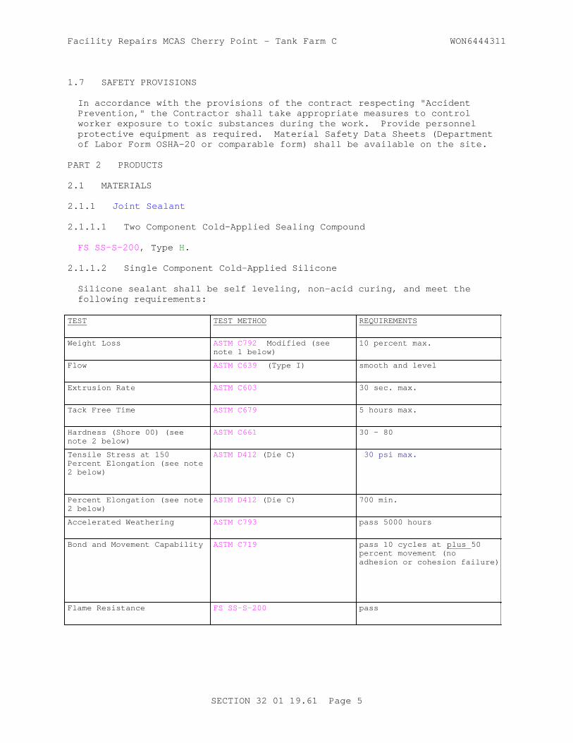
Facility Repairs MCAS Cherry Point - Tank Farm C WON6444311
1.7 SAFETY PROVISIONS
In accordance with the provisions of the contract respecting "Accident Prevention," the Contractor shall take appropriate measures to control worker exposure to toxic substances during the work. Provide personnel protective equipment as required. Material Safety Data Sheets (Department of Labor Form OSHA-20 or comparable form) shall be available on the site.
PART 2 PRODUCTS
2.1 MATERIALS
2.1.1 Joint Sealant
2.1.1.1 Two Component Cold-Applied Sealing Compound
FS SS-S-200 , Type H.
2.1.1.2 Single Component Cold-Applied Silicone
Silicone sealant shall be self leveling, non-acid curing, and meet the following requirements:
TEST TEST METHOD REQUIREMENTS
Weight Loss ASTM C792 Modified (see note 1 below)
10 percent max.
Flow ASTM C639 (Type I) smooth and level
Extrusion Rate ASTM C603 30 sec. max.
Tack Free Time ASTM C679 5 hours max.
Hardness (Shore 00) (see note 2 below)
ASTM C661 30 - 80
Tensile Stress at 150 Percent Elongation (see note 2 below)
ASTM D412 (Die C) 30 psi max.
Percent Elongation (see note 2 below)
ASTM D412 (Die C) 700 min.
Accelerated Weathering ASTM C793 pass 5000 hours
Bond and Movement Capability ASTM C719 pass 10 cycles at plus 50 percent movement (no adhesion or cohesion failure)
Flame Resistance FS SS-S-200 pass
SECTION 32 01 19.61 Page 5

Facility Repairs MCAS Cherry Point - Tank Farm C WON6444311
Notes:1. Percent weight loss of wet (uncured) sample after placing in forced-draft oven maintained at 158 degrees plus 1 degrees F for two hours.
2. Specimen cured 21 days at 73 degrees plus 1 degree F and 50 percent plus 5 percent humidity.
ACCELERATED WEATHERING FACTORY TEST REPORT. For the Accelerated Weathering test, in lieu of testing of actual joint sealant to be used on the project, a report of a factory test, performed within two years of contract award, may be submitted.
2.1.2 Primers
Select concrete primer recommended by the manufacturer of the proposed liquid joint sealant.
2.1.3 Bond Breakers
2.1.3.1 Blocking Media
Compressible, nonshrinkable, nonreactive with joint sealant and nonabsorption type such as plastic backer rod , free of oils or bitumens. Blocking media shall be consistent with the joint seal manufacturer's installation instructions and be at least 25 percent larger in diameter than the width of the cleaned and re-faced joints as shown.
2.1.3.2 Separating Tape
Polyethylene or polyester tape, 3 mil minimum thickness, or masking tape, nonreactive, nonabsorptive, adhesive-back tape, width equal to width of cleaned and refaced joints as indicated. Separating tape shall be consistent with the joint seal manufacturer's installation instructions.
PART 3 EXECUTION
3.1 JOINT PREPARATION
Unless otherwise indicated, remove existing material, saw, clean and reseal joints. Do not proceed with final cleaning operations by more than one working day in advance of sealant. Thoroughly clean joints by removing existing joint sealing compound, bond-breakers, dirt, and other foreign material with the equipment specified herein, but not limited thereto. Cleaning procedures which damage joints or previously repaired patches by chipping or spalling will not be permitted. Remove existing sealant to the required depth as indicated. Precise shape and size of existing joints vary, and conditions of joint walls and edges vary and include but are not limited to rounding, square edges, sloping, chips, voids, depressions, and projections.
3.1.1 Removal of Existing Material
Remove from the joint the existing sealants by using the specified routing tool. After cutting free the existing sealant from both joint faces, remove sealant to the depth required to accommodate the bond breaking material and to maintain the specified depth for the new sealant. For
SECTION 32 01 19.61 Page 6

Facility Repairs MCAS Cherry Point - Tank Farm C WON6444311
expansion joints, remove existing sealant to a depth of not less than one inch . When existing preformed expansion-joint material is more than one inch below the surface of the pavement, remove existing sealant to the top of the preformed joint filler . For joints other than expansion joints, remove in-place sealant to the depth as indicated. At the completion of routing operations, clean pavement surface with vacuum sweeper and clean the joint opening by blowing with compressed air. Protect previously cleaned joints from being contaminated by subsequent cleaning operations.
3.1.2 Refacing of Joints
Reface concrete joint walls. Refacing shall be by power-driven concrete saw specified herein to remove residual sealant and a minimum of concrete. Removal shall provide exposure of newly clean concrete. Remove burrs and irregularities from sides of joint faces. Immediately after sawing each joint, thoroughly clean saw cut and adjacent concrete surface. Flush with water under pressure, simultaneously blowing water out with compressed air until debris is removed from the joint. Protect adjacent previously cleaned joint spaces from receiving water and debris during the cleaning operation.
3.1.3 Final Cleaning of Joints
3.1.3.1 Sandblasting Cleaning
Following removal of existing sealant, and sawing, and immediately before resealing, thoroughly clean newly exposed concrete joint faces and pavement surface extending up to 2 inches from each joint edge by sandblasting until concrete surfaces in the joint space are free of sealants, dust, dirt, water and other foreign materials which would prevent bonding of new sealants to the concrete. Use sand particles of the proper size and quality for the work. Perform sandblasting with specified nozzles, air compressor, and other appurtenant equipment. Position nozzles to clean the joint faces. Make at least two passes; one for each joint face. Make as many passes as required for proper cleaning. Immediately prior to sealing the joint, blow out the joint spaces with compressed air until completely free of sand, water, and dust. Joints shall be dry before installation of joint sealant. Replace expansion joint filler material damaged in performing the work with new materials of the same type and dimensions as the existing material, or with appropriate blocking media.
3.1.4 Bond Breaker
At the time the joints receive the final cleaning and are dry, install bond breaker material as indicated with a steel wheel or other approved device.
3.1.4.1 Blocking Media (Backer Rod) (Except for Expansion Joints)
Plug or seal off the lower portion of the groove by installing the specified blocking media as indicated.
3.1.4.2 Separating Tape
Insert the specified tape as indicated.
3.1.5 Rate of Progress
The final stages of joint preparation, which include placement of bond breakers, if required, shall be limited to only that length of joint that can be resealed during the same workday.
SECTION 32 01 19.61 Page 7

Facility Repairs MCAS Cherry Point - Tank Farm C WON6444311
3.1.6 Disposal of Debris
Sweep from pavement surface to remove excess joint material, dirt, water, sand, and other debris by vacuum sweepers or hand brooms. Remove the debris immediately to a point off station.
3.2 PREPARATION OF SEALANT
3.2.1 Hot-Poured Type
Heat hot-poured sealing materials in accordance with safe heating temperature ranges recommended by the manufacturer. Withdraw and waste sealant that has been overheated or subjected to heating for over 3 hours or that remain in the applicator at the end of the day's operation. Heat sealant in specified equipment.
3.2.2 Cold-Applied, Two Component Type
Reject materials which contain water, hard caking of separated constituents, nonreversible jell, or other unsatisfactory conditions such as settlement of constituents into a soft mass that cannot be readily and uniformly remixed in the field with simple tools. In conformance with the manufacturer's recommendations, mix individual components in separate shipping containers before transferring components to appropriate reservoirs of application equipment. Thoroughly mix components to ensure homogeneity of components and incorporation of constituents at time of transfer. When necessary, for remixing prior to transfer, warm components to a temperature not exceeding 90 degrees F by placing components in heated storage or by other approved methods. In no case shall components be heated by direct flame or in single-walled, non-oil-bath heating kettles. Hand mixing of cold-applied two component sealant may be done at the option of the Contractor for sealants conforming to FS SS-S-200 , Type H.
3.3 INSTALLATION OF SEALANT
3.3.1 Test Section
Install a test section of 200 linear feet at the start of the sealing operation for each type sealant to be used. Test section shall meet contract requirements. The Contracting Officer shall be notified upon completion of the test section.
3.3.2 Time of Application
After approval of the test section, seal joints immediately following final cleaning and placing of bond breakers. Commence sealing joints when walls are dust free and dry, and when weather conditions meet joint seal manufacturer's instructions. If the above conditions cannot be met, or when rains interrupts sealing operations, reclean and permit the joints to dry prior to installing the sealant.
3.3.3 Sealing the Joints
Do not install joint sealant until joints to be sealed have been inspected and approved. Install bond breaker just prior to pouring sealant. Fill the joints with sealant from bottom up until joints are uniformly filled solid from bottom to top using the specified equipment for the type of sealant required. Fill joints to 1/4 inch below top of pavement within
SECTION 32 01 19.61 Page 8

Facility Repairs MCAS Cherry Point - Tank Farm C WON6444311
tolerances as indicated, and without formation of voids or entrapped air. Except as otherwise permitted, tool the sealant immediately after application to provide firm contact with the joint walls and to form the indicated sealant profile below the pavement surface. Remove excess sealant that has been inadvertently spilled on the pavement surface. When two-component sealants are placed, each day check hourly the proportioning capability of the equipment to determine that the preset volume output for each component is being maintained. The material used for these checks may be returned to the proper component reservoir. In no case shall two component sealants be installed using gravity methods and pouring spouts, except for approved hand mixing methods. When a primer is supplied or recommended by the manufacturer of a two component sealant, apply the primer evenly to the joint faces in accordance with the manufacturer's recommendations. Check sealed joints frequently to assure that newly installed sealant is cured to a tack-free condition within 3 hours. Protect new sealant from rain during curing period.
3.4 FIELD QUALITY CONTROL
3.4.1 Sampling Joint Seal
Obtain a one gallon sample of each type of joint seal on the project from material used for each 10,000 linear feet or less of joints sealed. Store samples according to joint seal manufacturer's instructions. Retain samples until final acceptance of the work by the Contracting Officer.
3.4.2 Joints
Inspect and approve joints which have been cleaned and have backer rods or bond breaking tape installed prior to sealing.
3.4.3 Joint Seal Test Section
Inspect joint seal test section. Correct deficiencies and obtain approval of test section by the Contracting Officer prior to installing joint seals.
3.4.4 Joint Sealer
Inspect installed joint seals for conformance to contract requirements, joint seal manufacturer's instructions, and the test section. Obtain approval for each joint seal installation.
3.5 ACCEPTANCE
Reject joint sealer that fails to cure properly, or fails to bond to joint walls, or reverts to the uncured state, or fails in cohesion, or shows excessive air voids, blisters, surface defects, swelling, or other deficiencies, or is not properly recessed within indicated tolerances. Remove rejected sealer and reclean and reseal joints in accordance with the specification. Perform removal and reseal work promptly by and at the expense of the Contractor.
-- End of Section --
SECTION 32 01 19.61 Page 9


Facility Repairs MCAS Cherry Point - Tank Farm C WON6444311
SECTION 32 01 29.61
PARTIAL DEPTH PATCHING OF RIGID PAVING11/08
PART 1 GENERAL
1.1 REFERENCES
The publications listed below form a part of this specification to the extent referenced. The publications are referred to within the text by the basic designation only.
AMERICAN ASSOCIATION OF STATE HIGHWAY AND TRANSPORTATION OFFICIALS (AASHTO)
AASHTO M 182 (2005; R 2012) Standard Specification for Burlap Cloth Made from Jute or Kenaf and Cotton Mats
ASTM INTERNATIONAL (ASTM)
ASTM C1059/C1059M (2013) Standard Specification for Latex Agents for Bonding Fresh to Hardened Concrete
ASTM C1260 (2014) Standard Test Method for Potential Alkali Reactivity of Aggregates (Mortar-Bar Method)
ASTM C131/C131M (2014) Standard Test Method for Resistance to Degradation of Small-Size Coarse Aggregate by Abrasion and Impact in the Los Angeles Machine
ASTM C136/C136M (2014) Standard Test Method for Sieve Analysis of Fine and Coarse Aggregates
ASTM C143/C143M (2015a) Standard Test Method for Slump of Hydraulic-Cement Concrete
ASTM C150/C150M (2016) Standard Specification for Portland Cement
ASTM C1581/C1581M (2009a) Standard Test Method for Determining Age at Cracking and Induced Tensile Stress Characteristics of Mortar and Concrete under Restrained Shrinkage
ASTM C1602/C1602M (2012) Standard Specification for Mixing Water Used in Production of Hydraulic Cement Concrete
ASTM C171 (2016) Standard Specification for Sheet Materials for Curing Concrete
ASTM C173/C173M (2016) Standard Test Method for Air
SECTION 32 01 29.61 Page 1

Facility Repairs MCAS Cherry Point - Tank Farm C WON6444311
Content of Freshly Mixed Concrete by the Volumetric Method
ASTM C192/C192M (2016) Standard Practice for Making and Curing Concrete Test Specimens in the Laboratory
ASTM C231/C231M (2014) Standard Test Method for Air Content of Freshly Mixed Concrete by the Pressure Method
ASTM C260/C260M (2010a) Standard Specification for Air-Entraining Admixtures for Concrete
ASTM C31/C31M (2015a; E 2016) Standard Practice for Making and Curing Concrete Test Specimens in the Field
ASTM C33/C33M (2016) Standard Specification for Concrete Aggregates
ASTM C39/C39M (2016) Standard Test Method for Compressive Strength of Cylindrical Concrete Specimens
ASTM C469/C469M (2014) Static Modulus of Elasticity and Poisson's Ratio of Concrete in Compression
ASTM C494/C494M (2015a) Standard Specification for Chemical Admixtures for Concrete
ASTM C531 (2000; R 2012) Linear Shrinkage and Coefficient of Thermal Expansion of Chemical-Resistant Mortars, Grouts, and Monolithic Surfacings, and Polymer Concretes
ASTM C666/C666M (2015) Resistance of Concrete to Rapid Freezing and Thawing
ASTM C685/C685M (2014) Concrete Made by Volumetric Batching and Continuous Mixing
ASTM C881/C881M (2015) Standard Specification for Epoxy-Resin-Base Bonding Systems for Concrete
ASTM C882/C882M (2013a) Bond Strength of Epoxy-Resin Systems Used with Concrete by Slant Shear
ASTM C94/C94M (2016) Standard Specification for Ready-Mixed Concrete
ASTM D1751 (2004; E 2013; R 2013) Standard Specification for Preformed Expansion Joint Filler for Concrete Paving and Structural Construction (Nonextruding and Resilient Bituminous Types)
SECTION 32 01 29.61 Page 2

Facility Repairs MCAS Cherry Point - Tank Farm C WON6444311
ASTM D1752 (2004a; R 2013) Standard Specification for Preformed Sponge Rubber Cork and Recycled PVC Expansion
ASTM D75/D75M (2014) Standard Practice for Sampling Aggregates
U.S. NATIONAL ARCHIVES AND RECORDS ADMINISTRATION (NARA)
29 CFR 1910 Occupational Safety and Health Standards
1.2 SUBMITTALS
Government approval is required for submittals with a "G" designation; submittals not having a "G" designation are for Contractor Quality Control approval. Submit the following in accordance with Section 01 33 00 SUBMITTAL PROCEDURES:
SD-03 Product Data
Mix Design ; GProprietary Cementitious Products ; G
SD-05 Design Data
Concrete Mix Design ; G
SD-06 Test Reports
Laboratory Test ResultsAggregates GradationCementConcrete SlumpConcrete Air ContentConcrete Strength (cylinder)Mixer Calibration and Efficiency
SD-07 Certificates
CementAggregateAdmixturesAbsorbent curing materialWaterproof SheetJoint FillerJoint Sealant
1.3 QUALITY ASSURANCE
1.3.1 Preconstruction Testing Of Materials
Submit proposed concrete mix design at least 30 days prior to placement. Provide mix design evaluation and certification by an approved engineering testing laboratory, and indicate the weight of each ingredient of the mixture, aggregate gradation, slump, air content, water-cement ratio, and 7-day and 28-day compressive strength test results. Include a complete list of materials including admixtures and applicable reference specifications. Place no concrete prior to approval of the proposed mix design. No deviation from the approved mix design is permitted without
SECTION 32 01 29.61 Page 3

Facility Repairs MCAS Cherry Point - Tank Farm C WON6444311
prior approval.
Within 24 hours of physical completion of laboratory testing, submit copies of test results for approval.
1.3.1.1 Cement
Test cement as prescribed in the referenced specification under which it is furnished. Cement may be accepted on the basis of mill tests and the manufacturer's certification of compliance with the specification.
1.3.1.2 Aggregate
Take aggregate gradation samples for laboratory testing in conformance with ASTM D75/D75M.
1.3.1.3 Proprietary Cementitious Products and Epoxy
At least 30 days before the material is used, submit certified copies of test results for the specific lots or batches to be used on the project, not more than 6 months old prior to use in the work.
Manufacturer's certifications may be submitted rather than laboratory test results for proprietary cementitious products. Include in the instructions details for substrate preparation, mixing, placing, finishing, curing and testing of the material. Include a minimum of three case histories documenting the use of the product in a similar freeze-thaw environment and airfield pavement condition. Certify compliance with the appropriate specification referenced herein. Place no materials without prior approval from the Contracting Officer.
1.3.2 Equipment; Approval, Maintenance, and Safety
Provide and use only dependable and well maintained equipment that is appropriate to accomplish the work specified. Allow sufficient time for assembly of equipment requiring such at the work site to permit thorough inspection, calibration of weighing and measuring devices, adjustment of parts, and the making of any repairs that may be required prior to the start of work.
a. Submit volumetric mixer calibration and efficiency test results. Results must be current within 6 months of concrete placement.
b. Provide Material Safety Data Sheets (MSDS) and Personal Protection Equipment (PPE) per 29 CFR 1910 .
1.4 DELIVERY, STORAGE, AND HANDLING
1.4.1 Cement
Deliver cement in bulk or in suitable bags used for packaging cements and store in a manner to prevent absorption of moisture.
1.4.2 Aggregate
Deliver, handle, and store aggregate in a manner to avoid breakage, segregation, or contamination by foreign materials.
SECTION 32 01 29.61 Page 4

Facility Repairs MCAS Cherry Point - Tank Farm C WON6444311
1.4.3 Other Materials
Deliver epoxy-resin, chemical admixtures and proprietary cementitious products to the site in such manner as to avoid damage or loss. Provide storage areas in a windowless and weatherproof, but ventilated, insulated noncombustible building, with provision nearby for conditioning the material to 70 to 85 degrees F for a period of 48 hours prior to use. Keep the ambient temperature in the storage area no higher than 100 degrees F .
1.5 Project/Site Conditions
Do not place concrete when weather conditions detrimentally affect the quality of the finished product. Do not place concrete when the air temperature is below 40 degrees F in the shade. When air temperature is likely to exceed 90 degrees F , provide concrete having a temperature not exceeding 90 degrees F when deposited. Keep the surface of placed concrete damp with a water fog until the approved curing medium is applied.
PART 2 PRODUCTS
2.1 MATERIALS
2.1.1 Coarse Aggregate
2.1.1.1 Composition
Provide coarse aggregate consisting of gravel, crushed gravel, crushed stone, or a combination thereof.
2.1.1.2 Quality
Provide aggregate , as delivered to the mixers, consisting of clean, hard, unweathered, and uncoated particles. Remove dust and other coatings from the coarse aggregate by adequate washing. Meet the requirements of ASTM C33/C33M, Class 4S for deleterious substances. Abrasion loss, when tested in accordance with ASTM C131/C131M, must not exceed 40 percent; the maximum allowable percentage for clay lumps and friable particles is 1.5 percent. Provide documentation of aggregate conforming to ASTM C136/C136M.
2.1.1.3 Particle Shape
Provide spherical or cubical shaped coarse aggregate particles.
2.1.1.4 Gradation
The maximum nominal size of the coarse aggregate is 1/2 inch . Provide well graded coarse aggregate, within the limits specified, and tested in accordance with ASTM C136/C136M, and conforming to the following grading requirements as delivered to the batching hoppers:
Sieve designation U.S.Standard square mesh
Percentage by weightpassing individual sieves
No. 4 to 1/2 inch
1/2 inch 100
3/8 inch 90-100
SECTION 32 01 29.61 Page 5
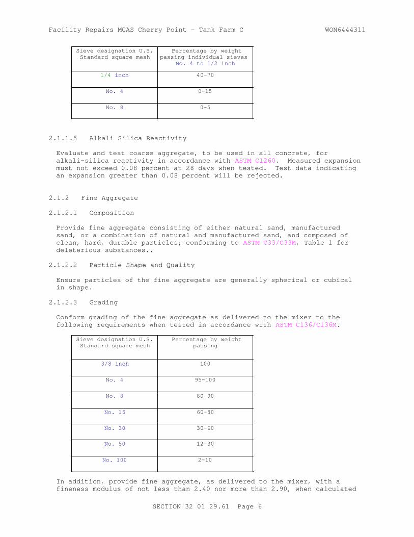
Facility Repairs MCAS Cherry Point - Tank Farm C WON6444311
Sieve designation U.S.Standard square mesh
Percentage by weightpassing individual sieves
No. 4 to 1/2 inch
1/4 inch 40-70
No. 4 0-15
No. 8 0-5
2.1.1.5 Alkali Silica Reactivity
Evaluate and test coarse aggregate, to be used in all concrete, for alkali-silica reactivity in accordance with ASTM C1260. Measured expansion must not exceed 0.08 percent at 28 days when tested. Test data indicating an expansion greater than 0.08 percent will be rejected.
2.1.2 Fine Aggregate
2.1.2.1 Composition
Provide fine aggregate consisting of either natural sand, manufactured sand, or a combination of natural and manufactured sand, and composed of clean, hard, durable particles; conforming to ASTM C33/C33M, Table 1 for deleterious substances..
2.1.2.2 Particle Shape and Quality
Ensure particles of the fine aggregate are generally spherical or cubical in shape.
2.1.2.3 Grading
Conform grading of the fine aggregate as delivered to the mixer to the following requirements when tested in accordance with ASTM C136/C136M.
Sieve designation U.S.Standard square mesh
Percentage by weightpassing
3/8 inch 100
No. 4 95-100
No. 8 80-90
No. 16 60-80
No. 30 30-60
No. 50 12-30
No. 100 2-10
In addition, provide fine aggregate, as delivered to the mixer, with a fineness modulus of not less than 2.40 nor more than 2.90, when calculated
SECTION 32 01 29.61 Page 6

Facility Repairs MCAS Cherry Point - Tank Farm C WON6444311
in accordance with ASTM C136/C136M.
2.1.2.4 Alkali Silica Reactivity
Evaluate and test fine aggregate to be used in all concrete for alkali-silica reactivity using the procedures described for coarse aggregate.
2.1.3 Admixtures
2.1.3.1 Air-Entraining Admixtures
Provide air-entraining admixtures conforming to ASTM C260/C260M.
2.1.3.2 Chemical Admixtures
ASTM C494/C494M. Where not shown or specified, the use of admixtures is subject to written approval of the Contracting Officer.
2.1.4 Cement
Provide portland cement conforming to ASTM C150/C150M, Type II . Provide low alkali cement if the proposed fine or coarse aggregate are found to have greater than 0.04 percent expansion when tested in accordance with paragraphs: Alkali Silica Reactivity.
2.1.4.1 Portland Cement Mix Design
Design the concrete mixture to produce a minimum flexural strength of 650 psi at 28 days of age, determined in conformance with ASTM C39/C39M and ASTM C192/C192M, using standard 6 by 12 inch cylinder specimens; and providing an air content by volume of 6 percent, plus or minus 1.5 percent, based on measurements made on concrete immediately after discharge from the mixer in conformance with ASTM C231/C231M.
The allowable range of slump is 1/2 to 2 inches when tested in accordance with ASTM C143/C143M. To minimize drying shrinkage, the maximum water-cement ratio by weight is 0.45.
2.1.5 Curing Materials
2.1.5.1 Burlap
Provide burlap conforming to AASHTO M 182.
2.1.5.2 Waterproof Sheet Materials
Provide waterproof sheet materials conforming to ASTM C171, Type optional, color white.
2.1.6 Bonding-Agents
2.1.6.1 Epoxy-Resin
Provide two component epoxy-resin material formulated to meet the requirements of ASTM C881/C881M, Type III, grade and class as approved, for use in bond coat applications and as a component of epoxy-resin concrete or mortar.
SECTION 32 01 29.61 Page 7

Facility Repairs MCAS Cherry Point - Tank Farm C WON6444311
Mix epoxy-resin grout components in the proportions recommended by the manufacturer. Condition the components to 70 to 85 degrees F for 48 hours prior to mixing. Mix the two epoxy components with a power-driven, explosion-proof stirring device in a metal or polyethylene container having a hemispherical bottom. Add the curing-agent component gradually to the epoxy-resin component with constant stirring until a uniform mixture is obtained. Stir such that the rate of entrained air is a minimum.
2.1.6.2 Latex
Provide latex bonding agent meeting the requirements of ASTM C1059/C1059M , Type II.
2.1.7 Joint Sealant
Provide joint sealant as specified in Section 32 01 19.61 RESEALING OF JOINTS IN RIGID PAVING.
2.1.8 Joint Filler
Provide joint filler material conforming to ASTM D1751 or ASTM D1752, Type II.
2.1.9 Water
Use only clean, fresh water, free from injurious amounts of oil, acid, salt, alkali, organic matter, or other deleterious substances. Water approved by Public Health authorities for domestic consumption may be accepted for use without being tested. Test water that is of questionable quality, in the opinion of the Contracting Officer, in accordance with ASTM C1602/C1602M and acceptance criteria of Table 1 of ASTM C94/C94M.
2.1.10 Proprietary Cementitious Products
A proprietary cementitious product is defined as a rigid material in its hardened state with an elastic modulus greater than 1,000,000 psi . Maximum size of aggregate used to extend the product is 3/4 inch . Test the product in accordance with the following test series. Replicate each test on three specimens. Report all three results for each test and use the average value for comparison with the specification requirements. Report the curing conditions for each test type.
2.1.10.1 Compressive Strength
Cast 3 by 6 inch cylinder specimens in accordance with ASTM C192/C192M and test in accordance with ASTM C39/C39M, using bonded or unbonded caps, after 3 hours and 1 day curing period. A minimum compressive strength of 3500 psi or greater is required at 3 hours and 1 day of age.
2.1.10.2 Bond Strength
Cast 3 by 6 inch cylinder specimens and test in accordance with ASTM C882/C882M. Cast the candidate material against a 30-degree wedge specimen consisting of the candidate material itself or an ordinary portland cement mixture. Test specimens, using bonded caps, after 1 day curing period. For a bond consisting of the candidate material bonded to OPC mortar, a minimum bond strength of 500 psi is required at 1 day of age. For a bond consisting of the candidate material bonded to itself, a minimum bond strength of 1000 psi is required at 1 day of age.
SECTION 32 01 29.61 Page 8

Facility Repairs MCAS Cherry Point - Tank Farm C WON6444311
2.1.10.3 Modulus of Elasticity
Cast 6 by 12 inch cylinder specimens in accordance with ASTM C192/C192M and test in accordance with ASTM C469/C469M, using bonded caps, after 3 day curing period. A maximum chord modulus of elasticity of 4,000,000 psi is required at 3 days of age.
2.1.10.4 Coefficient of Thermal Expansion
Cast 1 by 1 by 10-inches prismatic bar specimens and test in accordance with ASTM C531, after 3 days curing period. A maximum coefficient of 7 by
10-6 inch per inch per degree F is required at 3 days of age.
2.1.10.5 Shrinkage Potential
Cast 13 inch I.D. by 16 inch O.D. by 6 inch tall restrained toroidal specimens and test in accordance with ASTM C1581/C1581M . Start measuring strain after completion of casting. A maximum of 40 microstrain is required at 14 days of age. No cracking is permitted at 28 days of age.
2.1.10.6 Freeze-Thaw Resistance
Cast prismatic specimens in accordance with ASTM C192/C192M and test in accordance with ASTM C666/C666M, Procedure A. Begin freeze-thaw testing after specimens have been immersed in saturated lime-water for 3 days. Report the Durability Factor (DF) and the number of cycles to failure.
2.2 Neat Cement Grout
2.2.1 Sand-Cement Grout Bonding Course
Provide grout bonding course consisting of equal parts of Type I or II, portland cement and sand by dry weight, thoroughly mixed with water to yield a thick, creamy mixture; with a water-cement ratio no greater than 0.62 by weight. Sand must meet the requirements of the fine aggregate specified herein, except 100 percent must pass through a No. 8 sieve.
2.2.2 Sand-Cement Mortar for Filling Small Popouts
Provide mortar consisting of one part Type I or II portland cement and two parts sand by dry weight, thoroughly mixed with water to yield a thick, suitable mix; with a water-cement ratio no greater than 0.45 by weight. The sand must meet the requirements of the fine aggregate specified herein.
2.2.3 Dowels, Tie Bars, and Reinforcement
Provide dowels, tie bars, and reinforcement as indicated on the drawings.
PART 3 EXECUTION
3.1 PREPARATION OF EXISTING PAVEMENT
3.1.1 Preparation of Existing Surfaces
In the area to be patched, remove existing concrete to a minimum depth of 2 inches below the pavement surface adjacent to spalls and to such additional depth where necessary to expose a surface of sound, unweathered concrete that is uncontaminated by sealants, oils, greases, or deicing salts or
SECTION 32 01 29.61 Page 9

Facility Repairs MCAS Cherry Point - Tank Farm C WON6444311
solutions. Make a vertical saw cut at least 2 inches deep and 2 inches outside of the area needing repair. Accomplish concrete removal in spalled areas with light, hand-held, high-frequency chipping hammers weighing not more than 30 pounds or other approved hand tools. Do not use jack hammers weighing more than 30 pounds and do not use pavement breaker devices mounted on or pulled by mobile equipment.
Clean the cavity surface by sandblasting, blowing with compressed air, sweeping, and vacuums. Use sandblasting to remove all traces of sealer, oils, grease, rust, and other contaminants.
3.1.1.1 Joint Widening (Except Expansion Joints)
Saw joints having grooves less than 3/8 inch wide and less than one inch deep to a minimum width of 3/8 inch and to the minimum depth, of 1 inch .
3.1.2 Dowels, Tie Bars, and Reinforcement
Cut and remove to minimum dimensions indicated existing dowels and tie bars exposed in joints adjacent to the spall cavity. Perform cutting by saws, or other approved means; do not allow other cutting methods to damage concrete to remain. Clean to bare metal by sandblasting any existing reinforcement or dowels remaining exposed in the repair area. Remove any reinforcement that cannot be properly re-embedded in the new repair concrete. Cut and remove at the joint not less than 1/2 inch of existing exposed reinforcement that is continuous through the repair area and is embedded in the adjacent slab.
3.1.3 Preparation of Joints Adjacent to Spalls
Remove existing joint sealing and joint filler materials. Saw as indicated and install insert, cut to appropriate dimensions, to prevent contact between new patch material and existing concrete at existing joints. At the option of the Contractor, a bead of approved caulking material may be installed to preclude new patching material from getting around insert. Clean up any caulking material accidentally deposited on the prepared spall surface.
3.1.4 Disposal of Debris
Sweep from pavement surface to remove excess joint material, dirt, water, sand, and other debris by vacuum sweepers or hand brooms. Remove the debris immediately to a point off station.
3.1.5 Bonding Coat
Prior to placing concrete, wash the previously prepared surfaces with a high pressure water jet followed by an air jet to remove free water.
3.1.5.1 Neat Cement Grout
Coat the clean and dry surface, including sawed faces, with an approximate 1/16 inch thick coat of neat cement grout. Place the grout just prior to concrete placement and scrub with stiff bristle brushes to fill all voids and crevices in the spall cavity surface. Apply additional brush coats as needed to obtain the required thickness. The concrete patch material must be placed before the grout dries or sets. Remove dried or hardened grout by sandblasting and re-coat the cavity with fresh grout before placing concrete patch material.
SECTION 32 01 29.61 Page 10

Facility Repairs MCAS Cherry Point - Tank Farm C WON6444311
3.1.5.2 Epoxy-Resin
Limit epoxy-resin bonding coat to use on patches with a surface area of less than 2 feet square. Coat the clean and dry surface, including sawed faces, with a 20 to 40 mil thick film of the epoxy-resin grout. Place the epoxy-resin grout in one application, just prior to concrete placement, with the use of mechanical combination, mixing and spraying equipment, or two coat application with stiff brushes. Scrub the first brush coat into the concrete surface, followed by an additional brush coat to obtain the required thickness. When the brush method is used, the initial coat may be allowed to dry; however, apply the final coat just prior to placement of the concrete.
3.1.5.3 Proprietary Cementitious Products
Apply in accordance with the manufacturer's written instructions.
Test as prescribed in the referenced specification under which it is furnished. Cement may be accepted on the basis of mill tests and the manufacturer's certification of compliance with the specification, provided the cement is the product of a mill with a record for the production of high-quality cement for the past 3 years.
3.1.6 Popout Repair
Popouts, as used herein, are pavement surface defects caused by deterioration of unsatisfactory coarse aggregate, decaying of organic material such as wood or roots, mechanical accidents, or other reasons. Most popouts are indicated on the drawings by average diameter but the actual surface configuration will vary from circular to polygonal. Repair popouts as indicated using portland cement concrete for large popouts. Clean popout cavities of all dirt and contaminants prior to filling. As indicated on drawings, prepare popout areas by chipping the concrete to eliminate feather edging of the mortar or concrete repair material.
3.1.7 Patch Material Selection
Fill the prepared cavity with: Portland cement concrete or latex modified concrete for cavities more than 600 cubic inches in volume after removal operations; portland cement mortar for cavities between 50 and 600 cubic inches ; and epoxy resin mortar or latex modified mortar for those cavities less than 50 cubic inches in size. Proprietary cementitious patching materials may be used, subject to approval by the Contracting Officer.
3.2 BATCHING, MIXING AND PROPORTIONING
Provide facilities for the accurate measurement and control of each of the materials entering the concrete, mortar, or grout. Provide free access for the Contracting Officer to the batching and mixing plant at all times. Provide mixing equipment capable of combining the aggregate, cement, admixture, and water into a uniform mixture and discharging this mixture without segregation.
The use of volumetric batching and continuous mixing is acceptable, provided all operations are in accordance with ASTM C685/C685M.
SECTION 32 01 29.61 Page 11

Facility Repairs MCAS Cherry Point - Tank Farm C WON6444311
3.2.1 Equipment
Assemble dependable and operable equipment, allowing time for thorough inspection, calibration of weighing and measuring devices, adjustment of parts, and the making of any repairs that may be required prior to final approval and the commencement of work. Maintain the equipment in good working condition.
3.2.2 Conveying
Convey concrete from mixer to repair area as rapidly as practicable by methods which prevent segregation or loss of ingredients.
3.2.3 Facilities for Sampling
Provide facilities for readily obtaining representative samples of aggregate and concrete for test purposes. Furnish necessary platforms, tools, and equipment for obtaining samples.
3.2.4 Mix Proportions
Use proportions of materials entering into the concrete mixture in accordance with the approved mix design. Revise the mix design whenever necessary to maintain the workability, strength, and standard of quality required, and to meet the varying conditions encountered during the construction; however, no changes shall be made without prior approval.
3.2.5 Measurement
Provide equipment necessary to measure and control the amount of each material in each batch of concrete. Weigh bulk cement. Cement in unopened bags as packed by the manufacturer may be used without weighing. One bag of portland cement is considered as weighing 94 pounds . Measure mixing water and air-entraining admixtures by volume or by weight. Consider one gallon of water as weighing 8.33 pounds .
3.2.6 Workability
Maintain the slump of the concrete at the lowest practicable value, not exceeding the specified value.
3.3 PLACING
3.3.1 Portland Cement Concrete
Place concrete within 90 minutes after the introduction of the mixing water to the cement and aggregate or the introduction of the cement to the aggregate, and before the concrete has obtained its initial set, and before the sand-cement grout bonding course has dried or obtained its initial set. The temperature of the concrete, as deposited in the repair area, must be not less than 50 degrees F nor more than 90 degrees F . Deposit concrete as to require a minimum of re-handling and in such a manner so as to least disturb the sand-cement grout. Place concrete as indicated to maintain existing joints; do not allow new repair material to infiltrate or span existing joints indicated to remain. Place concrete continuously in each spall area. Do not allow workmen to walk on the bonding course surface or in the concrete during placing and finishing operations.
Consolidate the concrete by small spud vibrators not greater than one inch
SECTION 32 01 29.61 Page 12

Facility Repairs MCAS Cherry Point - Tank Farm C WON6444311
in diameter, except that repair areas less than 4 inches deep or one square foot in area may be consolidated by hand tamping or other approved means. To avoid pulling material away from patch edge and to maximize bond strength, work the finishing screed from the center of the patch out to the patch boundary. Fill all saw kerfs extending beyond the repair area with grout. Start finishing operations immediately after placement of the concrete. Match finished surface grade of patched areas to the existing surface grade of the adjacent undisturbed pavement. Keep screeding, floating, or troweling of patch material onto adjacent pavements to a minimum; remove loose or poorly bonded patch material from adjacent surfaces. Before the concrete becomes non-plastic, finish the surface with a broom to approximately match the surface finish of existing adjacent concrete pavement.
3.3.2 Epoxy-Resin Concrete and Mortar
Limit epoxy-resin bonding coat to use on patches with a surface area of less than 2 feet square. Place the epoxy resin materials in layers not over 2 inches thick. Make the time interval between placement of additional layers such that the temperature of the epoxy resin material does not exceed 140 degrees F at any time during hardening. Use mechanical vibrators and hand tampers to consolidate the concrete or mortar. Remove any repair material on the surrounding surfaces of the existing concrete before it hardens. Use an insert or other bond-breaking medium where the spalled area abuts a joint, to prevent bond at the joint face. Saw a reservoir for the joint sealant to the dimensions required for other joints. Thoroughly clean and seal the reservoir with the sealer specified for the joints.
3.3.3 Proprietary Cementitious Products
Perform placing, consolidating, finishing, and curing operations in accordance with the manufacturer's written instructions.
3.3.4 Joints
Construct new joints as detailed on the drawings and align with existing joints. After curing of the concrete, seal new joints as indicated.
3.4 FIELD QUALITY CONTROL
3.4.1 General Requirements
Furnish concrete samples, taken in the field and tested to determine the slump, air content, and strength of the concrete. Make test cylinders for determining conformance with the strength requirements of these specifications and, when required, for determining the time at which pavements may be placed in service. Determine air content in conformance with ASTM C231/C231M. Mold and cure test cylinders in conformance with ASTM C31/C31M and as specified below. Furnish all materials, labor, and facilities required for molding, curing, and protecting test cylinders at the site and under the supervision of the Contracting Officer. Include furnishing and operating water tanks in curing facilities for test beams, equipped with temperature-control devices that will automatically maintain the temperature of the water at 73 degrees F plus or minus 5 degrees F . Also furnish and maintain at the site, boxes or other facilities suitable for storing the specimens while in the mold at a temperature of 73 degrees F plus or minus 10 degrees F . Tests of the fresh concrete and of the hardened concrete cylinders are to be made by and at the expense of the
SECTION 32 01 29.61 Page 13
Facility Repairs MCAS Cherry Point - Tank Farm C WON6444311
Contractor. Test Proprietary Cementitious Products in accordance with the manufacturer's written instructions.
3.4.2 Specimens for Strength Tests
Sample concrete in the field and test to determine the slump, air content, and strength of the concrete. Make cylinders for each shift of placed concrete. Mold each group of test cylinders from the same batch of concrete, consisting of a sufficient number of specimens to provide two compressive-strength tests at each test age. Make one group of specimens during the first half of each shift, and the other during the last portion of the shift. However, at the start of paving operations and each time the aggregate source, aggregate characteristics, or mix design is changed, make one additional set of test cylinders.
Determine the air content and slump in conformance with ASTM C173/C173M and ASTM C143/C143M, respectively. Mold and cure test cylinders in conformance with ASTM C31/C31M. Furnish and maintain at the site, boxes or other facilities suitable for storing the specimens while in the mold at a temperature of 73 degrees F plus or minus 10 degrees F . Test cylinders in accordance with ASTM C39/C39M.
3.4.2.1 Test Results
Remove concrete not meeting strength, consistency, and air content requirements and provide new acceptable concrete. The removal and replacement method or methods are subject to approval of the Contracting Officer.
3.4.2.2 Acceptance
Reject any spall repair material that cracks, or delaminates, or loses bond partly or completely, or causes spalling of adjacent portland cement concrete, or is not separated properly from adjacent slabs at joints, or fails to cure uniformly and completely, or is otherwise defective. Remove all unacceptable repairs, including new damaged areas adjacent to new spall patches, and provide new repairs meeting the specifications.
3.5 FINISHING
Start finishing operations immediately after placement of the concrete. Finished surfaces of patched areas are to approximate surface texture of the adjacent undisturbed pavements.
3.6 CURING
Cure the concrete by protection against loss of moisture and rapid temperature changes for a period of not less than 7 days from the beginning of the curing operation. Protect unhardened concrete from rain and flowing water. Provide all equipment needed for adequate curing and protection of the concrete on hand and ready to install before actual concrete placement begins. Cure proprietary cementitious products in accordance with manufacturer's recommendations. Failure to comply with curing requirements will be cause for immediate suspension of concreting operations.
3.6.1 Moist Curing
Moist-cure all portland cement concrete patches for the first 24-hours after finishing. Immediately after the finishing operations are complete
SECTION 32 01 29.61 Page 14

Facility Repairs MCAS Cherry Point - Tank Farm C WON6444311
and the concrete is set sufficiently to prevent marring the surface, cover the entire surface of the newly laid concrete with approved wetted burlap, and keep wet for a period of not less than 24 hours. Keep the surface of the newly laid concrete moist until the burlap coverings are in place. Ensure that moist curing is continuous 24 hours per day and that the entire surface is wet, by having an approved work system. Continue curing the concrete for the duration of the required curing period by this method or one of the methods specified below.
3.6.2 Waterproof-Paper Blankets or Impermeable Sheets
Immediately after removing the covering used for initial curing, moisten the exposed concrete surfaces with a fine spray of water and cover with waterproof-paper blankets, polyethylene-coated-burlap blankets, or impermeable sheets. Saturate polyethylene-coated burlap with water before placing. Place sheets with the light-colored side up. Overlap sheets not less than 12 inches with edges taped or secured to form a completely closed joint. Weight down coverings to prevent displacement or billowing from winds. Immediately repair tears or holes appearing during the curing by patching.
3.6.3 Membrane-Forming Curing Compound
Apply membrane -forming curing compound immediately to exposed concrete surfaces after removing burlap coverings. Apply the curing compound with an overlapping coverage that will give a two-coat application at a coverage of not more than 200 square feet per gallon for both coats. When application is made by hand-operated sprayers, apply the second coat in a direction approximately at right angles to the first coat.
Cure concrete properly at joints, but do not allow absorbent curing compound to enter joints that are to be sealed with joint-sealing compounds. Provide a uniform, continuous, cohesive compound film that will not check, crack, or peel, and that will be free from pinholes and other imperfections. Respray concrete surfaces that are subjected to heavy rainfall within 3 hours after the curing compound has been applied at the coverage specified above and at no additional cost to the Government. Respray areas covered with absorbent curing material that are damaged by pedestrian and vehicular traffic or by subsequent construction operations within the specified curing period at no additional cost to the Government.
3.7 FINISH TOLERANCE
Provide finished surfaces of patched areas meeting the grade of the adjoining pavements without deviations more than 1/8 inch from a true plan surface within the patched area.
3.8 PAVEMENT PROTECTION
Protect the patched areas against damage prior to final acceptance of the work by the Government. Exclude traffic from the patched areas by erecting and maintaining barricades and signs until the completion of the curing period of the concrete.
3.9 JOINTS
Provide joints conforming in detail and in alignment with the existing joints. After curing of the concrete, prepare and seal the joints in accordance with Section 32 01 19.61 RESEALING OF JOINTS IN RIGID PAVEMENTS.
SECTION 32 01 29.61 Page 15

Facility Repairs MCAS Cherry Point - Tank Farm C WON6444311
-- End of Section --
SECTION 32 01 29.61 Page 16

Facility Repairs MCAS Cherry Point - Tank Farm C WON6444311
SECTION 32 11 23
AGGREGATE AND/OR GRADED-CRUSHED AGGREGATE BASE COURSE08/08
PART 1 GENERAL
1.1 REFERENCES
The publications listed below form a part of this specification to the extent referenced. The publications are referred to in the text by basic designation only.
AMERICAN ASSOCIATION OF STATE HIGHWAY AND TRANSPORTATION OFFICIALS (AASHTO)
AASHTO T 180 (2015) Standard Method of Test for Moisture-Density Relations of Soils Using a 4.54-kg (10-lb) Rammer and a 457-mm (18-in.) Drop
AASHTO T 224 (2010) Standard Method of Test for Correction for Coarse Particles in the Soil Compaction Test
ASTM INTERNATIONAL (ASTM)
ASTM C117 (2013) Standard Test Method for Materials Finer than 75-um (No. 200) Sieve in Mineral Aggregates by Washing
ASTM C127 (2015) Standard Test Method for Density, Relative Density (Specific Gravity), and Absorption of Coarse Aggregate
ASTM C128 (2015) Standard Test Method for Density, Relative Density (Specific Gravity), and Absorption of Fine Aggregate
ASTM C131/C131M (2014) Standard Test Method for Resistance to Degradation of Small-Size Coarse Aggregate by Abrasion and Impact in the Los Angeles Machine
ASTM C136/C136M (2014) Standard Test Method for Sieve Analysis of Fine and Coarse Aggregates
ASTM C29/C29M (2016) Standard Test Method for Bulk Density ("Unit Weight") and Voids in Aggregate
ASTM D1556/D1556M (2015; E 2016) Standard Test Method for Density and Unit Weight of Soil in Place by Sand-Cone Method
ASTM D1557 (2012; E 2015) Standard Test Methods for Laboratory Compaction Characteristics of
SECTION 32 11 23 Page 1
Facility Repairs MCAS Cherry Point - Tank Farm C WON6444311
Soil Using Modified Effort (56,000 ft-lbf/ft3) (2700 kN-m/m3)
ASTM D2167 (2015) Density and Unit Weight of Soil in Place by the Rubber Balloon Method
ASTM D2487 (2011) Soils for Engineering Purposes (Unified Soil Classification System)
ASTM D4318 (2010; E 2014) Liquid Limit, Plastic Limit, and Plasticity Index of Soils
ASTM D5821 (2013) Standard Test Method for Determining the Percentage of Fractured Particles in Coarse Aggregate
ASTM D6938 (2015) Standard Test Method for In-Place Density and Water Content of Soil and Soil-Aggregate by Nuclear Methods (Shallow Depth)
ASTM D75/D75M (2014) Standard Practice for Sampling Aggregates
ASTM E11 (2015) Wire Cloth and Sieves for Testing Purposes
1.2 DEFINITIONS
For the purposes of this specification, the following definitions apply.
1.2.1 Aggregate Base Course
Aggregate base course (ABC) is well graded, durable aggregate uniformly moistened and mechanically stabilized by compaction.
1.2.2 Degree of Compaction
Degree of compaction required, except as noted in the second sentence, is expressed as a percentage of the maximum laboratory dry density obtained by the test procedure presented in ASTM D1557 abbreviated as a percent of laboratory maximum dry density. Since ASTM D1557 applies only to soils that have 30 percent or less by weight of their particles retained on the 3/4 inch sieve, the degree of compaction for material having more than 30 percent by weight of their particles retained on the 3/4 inch sieve are expressed as a percentage of the laboratory maximum dry density in accordance with AASHTO T 180 Method D and corrected with AASHTO T 224 .
1.3 SUBMITTALS
Government approval is required for submittals with a "G" designation; submittals not having a "G" designation are for Contractor Quality Control approval. Submit the following in accordance with Section 01 33 00 SUBMITTAL PROCEDURES:
SD-03 Product Data
Plant, Equipment, and Tools
SECTION 32 11 23 Page 2

Facility Repairs MCAS Cherry Point - Tank Farm C WON6444311
SD-06 Test Reports
Sampling and Testing ; GField Density Tests ; G
1.4 QUALITY ASSURANCE
Sampling and testing are the responsibility of the Contractor and performed by a testing laboratory approved in accordance with Section 01 45 00.00 20 QUALITY CONTROL. Work requiring testing will not be permitted until the testing laboratory has been inspected and approved. Test the materials to establish compliance with the specified requirements; perform testing at the specified frequency. The Contracting Officer may specify the time and location of the tests. Furnish copies of test results to the Contracting Officer within 24 hours of completion of the tests.
1.4.1 Sampling
Take samples for laboratory testing in conformance with ASTM D75/D75M. When deemed necessary, the sampling will be observed by the Contracting Officer.
1.4.2 Tests
Perform the following tests in conformance with the applicable standards listed.
1.4.2.1 Sieve Analysis
Make sieve analysis in conformance with ASTM C117 and ASTM C136/C136M. Sieves shall conform to ASTM E11.
1.4.2.2 Liquid Limit and Plasticity Index
Determine liquid limit and plasticity index in accordance with ASTM D4318.
1.4.2.3 Moisture-Density Determinations
Determine the laboratory maximum dry density and optimum moisture content in accordance with AASHTO T 180 , Method D and corrected with AASHTO T 224 .
1.4.2.4 Field Density Tests
Measure field density in accordance with ASTM D1556/D1556M , ASTM D2167 or ASTM D6938. For the method presented in ASTM D1556/D1556M use the base plate as shown in the drawing. For the method presented in ASTM D6938 check the calibration curves and adjust them, if necessary, using only the sand cone method as described in paragraph Calibration, of the ASTM publication. Tests performed in accordance with ASTM D6938 result in a wet unit weight of soil, and ASTM D6938 shall be used to determine the moisture content of the soil. The calibration curves furnished with the moisture gauges shall also be checked along with density calibration checks as described in ASTM D6938. The calibration checks of both the density and moisture gauges shall be made by the prepared containers of material method, as described in paragraph Calibration of ASTM D6938, on each different type of material being tested at the beginning of a job and at intervals as directed.
a. Submit certified copies of test results for approval not less than 30
SECTION 32 11 23 Page 3

Facility Repairs MCAS Cherry Point - Tank Farm C WON6444311
days before material is required for the work.
b. Submit calibration curves and related test results prior to using the device or equipment being calibrated.
c. Submit copies of field test results within 24 hours after the tests are performed.
1.4.2.5 Wear Test
Perform wear tests on ABC course material in conformance with ASTM C131/C131M.
1.4.2.6 Weight of Slag
Determine weight per cubic foot of slag in accordance with ASTM C29/C29M on the ABC course material.
1.4.3 Testing Frequency
1.4.3.1 Initial Tests
Perform one of each of the following tests, on the proposed material prior to commencing construction, to demonstrate that the proposed material meets all specified requirements when furnished. If materials from more than one source are going to be utilized, this testing shall be completed for each source.
a. Sieve Analysis including the No. 635 sieve.
b. Liquid limit and plasticity index.
c. Moisture-density relationship.
d. Wear.
e. Weight per cubic foot of Slag.
1.4.3.2 In Place Tests
Perform each of the following tests on samples taken from the placed and compacted ABC. Samples shall be taken and tested at the rates indicated.
a. Perform density tests on every lift of material placed and at a frequency of one set of tests for every 250 square yards , or portion thereof, of completed area.
b. Perform sieve analysis including the No. 635 sieve on every lift of material placed and at a frequency of one sieve analysis for every 500 square yards , or portion thereof, of material placed.
c. Perform liquid limit and plasticity index tests at the same frequency as the sieve analysis.
d. Measure the total thickness of the base course at intervals, in such a manner as to ensure one measurement for each 500 square yards of base course. Measurements shall be made in 3 inch diameter test holes penetrating the base course.
SECTION 32 11 23 Page 4

Facility Repairs MCAS Cherry Point - Tank Farm C WON6444311
1.4.4 Approval of Material
Select the source of the material 30 days prior to the time the material will be required in the work. Tentative approval of material will be based on initial test results. Final approval of the materials will be based on sieve analysis, liquid limit, and plasticity index tests performed on samples taken from the completed and fully compacted course(s).
1.5 ENVIRONMENTAL REQUIREMENTS
Perform construction when the atmospheric temperature is above 35 degrees F . When the temperature falls below 35 degrees F , protect all completed areas by approved methods against detrimental effects of freezing. Correct completed areas damaged by freezing, rainfall, or other weather conditions to meet specified requirements.
PART 2 PRODUCTS
2.1 PLANT, EQUIPMENT, AND TOOLS
All plant, equipment, and tools used in the performance of the work will be subject to approval before the work is started and shall be maintained in satisfactory working condition at all times. Submit a list of proposed equipment, including descriptive data. Provide adequate equipment having the capability of producing the required compaction, meeting grade controls, thickness control, and smoothness requirements as set forth herein.
2.2 AGGREGATES
Provide ABC consisting of clean, sound, durable particles of crushed stone, crushed slag, crushed gravel, crushed recycled concrete, angular sand, or other approved material. ABC shall be free of lumps of clay, organic matter, and other objectionable materials or coatings. The portion retained on the No. 4 sieve is known as coarse aggregate; that portion passing the No. 4 sieve is known as fine aggregate.
2.2.1 Coarse Aggregate
Provide coarse aggregates with angular particles of uniform density. When the coarse aggregate is supplied from more than one source, aggregate from each source shall meet the specified requirements and shall be stockpiled separately.
a. Crushed Gravel: Crushed gravel manufactured by crushing gravels, and meets all the requirements specified below.
b. Crushed Stone: Provide crushed stone consisting of freshly mined quarry rock, meeting all the requirements specified below.
c. Crushed Recycled Concrete: Provide crushed recycled concrete consisting of previously hardened portland cement concrete or other concrete containing pozzolanic binder material. The recycled material shall be free of all reinforcing steel, bituminous concrete surfacing, and any other foreign material and shall be crushed and processed to meet the required gradations for coarse aggregate. Reject recycled concrete aggregate exceeding this value. Crushed recycled concrete must meet all other applicable requirements specified below.
SECTION 32 11 23 Page 5

Facility Repairs MCAS Cherry Point - Tank Farm C WON6444311
d. Crushed Slag: Crushed slag is an air-cooled blast-furnace product having an air dry unit weight of not less than 70 pcf as determined by ASTM C29/C29M, and meets all the requirements specified below.
2.2.1.1 Aggregate Base Course
ABC coarse aggregate shall not show more than 50 percent loss when subjected to the Los Angeles abrasion test in accordance with ASTM C131/C131M. The amount of flat and elongated particles shall not exceed 30 percent. A flat particle is one having a ratio of width to thickness greater than 3; an elongated particle is one having a ratio of length to width greater than 3. In the portion retained on each sieve specified, the crushed aggregates shall contain at least 50 percent by weight of crushed pieces having two or more freshly fractured faces determined in accordance with ASTM D5821. When two fractures are contiguous, the angle between planes of the fractures must be at least 30 degrees in order to count as two fractured faces. Crushed gravel shall be manufactured from gravel particles 50 percent of which, by weight, are retained on the maximum size sieve listed in TABLE 1.
2.2.2 Fine Aggregate
Fine aggregates shall be angular particles of uniform density. When the fine aggregate is supplied from more than one source, aggregate from each source shall meet the specified requirements.
2.2.2.1 Aggregate Base Course
ABC fine aggregate shall consist of screenings, angular sand, crushed recycled concrete fines, or other finely divided mineral matter processed or naturally combined with the coarse aggregate.
2.2.3 Gradation Requirements
Apply the specified gradation requirements to the completed base course. The aggregates shall be continuously well graded within the limits specified in TABLE 1. Sieves shall conform to ASTM E11.
TABLE 1. GRADATION OF AGGREGATES
Percentage by Weight Passing Square-Mesh Sieve
Sieve Designation No. 2
2 inch ---
1-1/2 inch 100
1 inch 60-100
1/2 inch 30-65
No. 4 20-50
SECTION 32 11 23 Page 6

Facility Repairs MCAS Cherry Point - Tank Farm C WON6444311
TABLE 1. GRADATION OF AGGREGATES
Percentage by Weight Passing Square-Mesh Sieve
Sieve Designation No. 2
No. 10 15-40
No. 40 5-25
No. 200 0-8
NOTE 1: Particles having diameters less than No. 635 shall not be in excess of 3 percent by weight of the total sample tested.
NOTE 2: The values are based on aggregates of uniform specific gravity. If materials from different sources are used for the coarse and fine aggregates, they shall be tested in accordance with ASTM C127 and ASTM C128 to determine their specific gravities. If the specific gravities vary by more than 10 percent, the percentages passing the various sieves shall be corrected as directed by the Contracting Officer.
2.3 LIQUID LIMIT AND PLASTICITY INDEX
Apply liquid limit and plasticity index requirements to the completed course and to any component that is blended to meet the required gradation. The portion of any component or of the completed course passing the No. 40 sieve shall be either nonplastic or have a liquid limit not greater than 25 and a plasticity index not greater than 5.
PART 3 EXECUTION
3.1 GENERAL REQUIREMENTS
When the ABC is constructed in more than one layer, clean the previously constructed layer of loose and foreign matter by sweeping with power sweepers or power brooms, except that hand brooms may be used in areas where power cleaning is not practicable. Provide adequate drainage during the entire period of construction to prevent water from collecting or standing on the working area. Provide line and grade stakes as necessary for control. Grade stakes shall be in lines parallel to the centerline of the area under construction and suitably spaced for string lining.
3.2 OPERATION OF AGGREGATE SOURCES
Clearing, stripping, and excavating are the responsibility of the Contractor. Operate the aggregate sources to produce the quantity and quality of materials meeting the specified requirements in the specified time limit. Aggregate sources on private lands shall be conditioned in agreement with local laws or authorities.
3.3 STOCKPILING MATERIAL
Clear and level storage sites prior to stockpiling of material. Stockpile all materials, including approved material available from excavation and grading, in the manner and at the locations designated. Aggregates shall be stockpiled on the cleared and leveled areas designated by the
SECTION 32 11 23 Page 7

Facility Repairs MCAS Cherry Point - Tank Farm C WON6444311
Contracting Officer to prevent segregation. Materials obtained from different sources shall be stockpiled separately.
3.4 PREPARATION OF UNDERLYING COURSE
Prior to constructing the base course(s), the underlying course or subgrade shall be cleaned of all foreign substances. At the time of construction of the base course(s), the underlying course shall contain no frozen material. The surface of the underlying course or subgrade shall meet specified compaction and surface tolerances. The underlying course shall conform to Section 31 23 00.00 20 EXCAVAION AND FILL . Ruts or soft yielding spots in the underlying courses, areas having inadequate compaction, and deviations of the surface from the requirements set forth herein shall be corrected by loosening and removing soft or unsatisfactory material and by adding approved material, reshaping to line and grade, and recompacting to specified density requirements. For cohesionless underlying courses containing sands or gravels, as defined in ASTM D2487, the surface shall be stabilized prior to placement of the base course(s). Stabilization shall be accomplished by mixing ABC into the underlying course and compacting by approved methods. The stabilized material shall be considered as part of the underlying course and shall meet all requirements of the underlying course. The finished underlying course shall not be disturbed by traffic or other operations and shall be maintained in a satisfactory condition until the base course is placed.
3.5 INSTALLATION
3.5.1 Mixing the Materials
Mix the coarse and fine aggregates in a stationary plant, or in a traveling plant or bucket loader on an approved paved working area. Make adjustments in mixing procedures or in equipment, as directed, to obtain true grades, to minimize segregation or degradation, to obtain the required water content, and to insure a satisfactory base course meeting all requirements of this specification.
3.5.2 Placing
Place the mixed material on the prepared subgrade or subbase in layers of uniform thickness with an approved spreader. When a compacted layer 6 inches or less in thickness is required, place the material in a single layer. When a compacted layer in excess of 6 inches is required, place the material in layers of equal thickness. No layer shall be thicker than 6 inches or thinner than 3 inches when compacted. The layers shall be so placed that when compacted they will be true to the grades or levels required with the least possible surface disturbance. Where the base course is placed in more than one layer, the previously constructed layers shall be cleaned of loose and foreign matter by sweeping with power sweepers, power brooms, or hand brooms, as directed. Such adjustments in placing procedures or equipment shall be made as may be directed to obtain true grades, to minimize segregation and degradation, to adjust the water content, and to insure an acceptable base course.
3.5.3 Grade Control
The finished and completed base course shall conform to the lines, grades, and cross sections shown. Underlying material(s) shall be excavated and prepared at sufficient depth for the required base course thickness so that the finished base course and the subsequent surface course will meet the
SECTION 32 11 23 Page 8

Facility Repairs MCAS Cherry Point - Tank Farm C WON6444311
designated grades.
3.5.4 Edges of Base Course
The base course(s) shall be placed so that the completed section will be a minimum of 1 foot wider, on all sides, than the next layer that will be placed above it. Additionally, place approved fill material along the outer edges of the base course in sufficient quantities to compact to the thickness of the course being constructed, or to the thickness of each layer in a multiple layer course, allowing in each operation at least a 2 foot width of this material to be rolled and compacted simultaneously with rolling and compacting of each layer of base course. If this base course material is to be placed adjacent to another pavement section, then the layers for both of these sections shall be placed and compacted along this edge at the same time.
3.5.5 Compaction
Compact each layer of the base course, as specified, with approved compaction equipment. Maintain water content during the compaction procedure to within plus or minus 2 percent of the optimum water content determined from laboratory tests as specified in this Section. Begin rolling at the outside edge of the surface and proceed to the center, overlapping on successive trips at least one-half the width of the roller. Alternate trips of the roller shall be slightly different lengths. Speed of the roller shall be such that displacement of the aggregate does not occur. In all places not accessible to the rollers, the mixture shall be compacted with hand-operated power tampers. Continue compaction until each layer has a degree of compaction that is at least 95 percent of laboratory maximum density through the full depth of the layer. Make such adjustments in compacting or finishing procedures as may be directed to obtain true grades, to minimize segregation and degradation, to reduce or increase water content, and to ensure a satisfactory base course. Any materials that are found to be unsatisfactory shall be removed and replaced with satisfactory material or reworked, as directed, to meet the requirements of this specification.
3.5.6 Thickness
Construct the compacted thickness of the base course as indicated. No individual layer shall be thicker than 6 inches nor be thinner than 3 inches in compacted thickness. The total compacted thickness of the base course(s) shall be within 1/2 inch of the thickness indicated. Where the measured thickness is more than 1/2 inch deficient, correct such areas by scarifying, adding new material of proper gradation, reblading, and recompacting as directed. Where the measured thickness is more than 1/2 inch thicker than indicated, the course shall be considered as conforming to the specified thickness requirements. Average job thickness shall be the average of all thickness measurements taken for the job, but shall be within 1/4 inch of the thickness indicated. The total thickness of the base course shall be measured at intervals in such a manner as to ensure one measurement for each 500 square yards of base course. Measurements shall be made in 3 inch diameter test holes penetrating the base course.
3.5.7 Proof Rolling
Proof rolling of the areas indicated shall be in addition to the compaction specified and shall consist of the application of 4 coverages with a heavy pneumatic-tired roller having four or more tires, each loaded to a minimum
SECTION 32 11 23 Page 9

Facility Repairs MCAS Cherry Point - Tank Farm C WON6444311
of 30,000 pounds and inflated to a minimum of 125 psi . In areas designated, apply proof rolling to the top of the underlying material on which the base course is laid and to each layer of base course top of the completed ABC course. Maintain water content of the underlying material at optimum or at the percentage directed from start of compaction to completion of proof rolling of that layer. Water content of each layer of the base course shall be maintained at the optimum percentage directed from start of compaction to completion of proof rolling. Any base course materials or any underlying materials that produce unsatisfactory results by proof rolling shall be removed and replaced with satisfactory materials, recompacted and proof rolled to meet these specifications.
3.5.8 Finishing
The surface of the top layer of base course shall be finished after final compaction and proof rolling by cutting any overbuild to grade and rolling with a steel-wheeled roller. Thin layers of material shall not be added to the top layer of base course to meet grade. If the elevation of the top layer of base course is 1/2 inch or more below grade, then the top layer should be scarified to a depth of at least 3 inches and new material shall be blended in and compacted to bring to grade. Adjustments to rolling and finishing procedures shall be made as directed to minimize segregation and degradation, obtain grades, maintain moisture content, and insure an acceptable base course. Should the surface become rough, corrugated, uneven in texture, or traffic marked prior to completion, the unsatisfactory portion shall be scarified, reworked and recompacted or it shall be replaced as directed.
3.5.9 Smoothness
The surface of the top layer shall show no deviations in excess of 3/8 inch when tested with a 12 foot straightedge. Take measurements in successive positions parallel to the centerline of the area to be paved. Measurements shall also be taken perpendicular to the centerline at 50 foot intervals. Deviations exceeding this amount shall be corrected by removing material and replacing with new material, or by reworking existing material and compacting it to meet these specifications.
3.6 TRAFFIC
Do not allow traffic on the completed base course.
3.7 MAINTENANCE
Maintain the base course in a satisfactory condition until the full pavement section is completed and accepted. Maintenance shall include immediate repairs to any defects and shall be repeated as often as necessary to keep the area intact. Any base course that is not paved over prior to the onset of winter, shall be retested to verify that it still complies with the requirements of this specification. Any area of base course that is damaged shall be reworked or replaced as necessary to comply with this specification.
3.8 DISPOSAL OF UNSATISFACTORY MATERIALS
Dispose of any unsuitable materials that must be removed as directed . No additional payments will be made for materials that must be replaced.
-- End of Section --
SECTION 32 11 23 Page 10

Facility Repairs MCAS Cherry Point - Tank Farm C WON6444311
SECTION 32 12 10
BITUMINOUS TACK AND PRIME COATS08/08
PART 1 GENERAL
1.1 REFERENCES
The publications listed below form a part of this specification to the extent referenced. The publications are referred to within the text by the basic designation only.
AMERICAN ASSOCIATION OF STATE HIGHWAY AND TRANSPORTATION OFFICIALS (AASHTO)
AASHTO M 81 (1992; R 2012) Standard Specification for Cutback Asphalt (Rapid-Curing Type)
AASHTO T 102 (2009; R 2013) Standard Method of Test for Spot Test of Asphaltic Materials
AASHTO T 40 (2002; R 2006) Sampling Bituminous Materials
ASTM INTERNATIONAL (ASTM)
ASTM D140/D140M (2015) Standard Practice for Sampling Bituminous Materials
ASTM D2995 (1999; R 2009) Determining Application Rate of Bituminous Distributors
ASTM D977 (2013; E 2014) Emulsified Asphalt
1.2 SUBMITTALS
Government approval is required for submittals with a "G" designation; submittals not having a "G" designation are for Contractor Quality Control approval. Submit the following in accordance with Section 01 33 00 SUBMITTAL PROCEDURES:
SD-06 Test Reports
Sampling and Testing
1.3 QUALITY ASSURANCE
1.4 DELIVERY, STORAGE, AND HANDLING
Inspect the materials delivered to the site for contamination and damage. Unload and store the materials with a minimum of handling.
SECTION 32 12 10 Page 1
Facility Repairs MCAS Cherry Point - Tank Farm C WON6444311
1.5 ENVIRONMENTAL REQUIREMENTS
Apply bituminous coat only when the surface to receive the bituminous coat is dry. Apply bituminous coat only when the atmospheric temperature in the shade is 50 degrees F or above and when the temperature has not been below 35 degrees F for the 12 hours prior to application, unless otherwise directed.
PART 2 PRODUCTS
2.1 PLANT, EQUIPMENT, MACHINES AND TOOLS
Plant, equipment, machines and tools used in the work are subject to approval and must be maintained in a satisfactory working condition at all times. Calibrated equipment such as asphalt distributors, scales, batching equipment, spreaders and similar equipment, must have been recalibrated by a calibration laboratory within 12 months prior to commencing work.
2.1.1 Bituminous Distributor
Provide a distributor with pneumatic tires of such size and number that the load produced on the base surface does not exceed 650 psi of tire width to prevent rutting, shoving or otherwise damaging the base surface or other layers in the pavement structure. Design and equip the distributor to spray the bituminous material in a uniform coverage at the specified temperature, at readily determined and controlled rates from 0.05 to 2.0 gallons per square yard , with a pressure range of 25 to 75 psi and with an allowable variation from the specified rate of not more than plus or minus 5 percent, and at variable widths. Include with the distributor equipment a separate power unit for the bitumen pump, full-circulation spray bars, tachometer, pressure gauges, volume-measuring devices, adequate heaters for heating of materials to the proper application temperature, a thermometer for reading the temperature of tank contents, and a hand hose attachment suitable for applying bituminous material manually to areas inaccessible to the distributor. Equip the distributor to circulate and agitate the bituminous material during the heating process.
2.1.2 Heating Equipment for Storage Tanks
The equipment for heating the bituminous material shall be steam, electric, or hot oil heaters. Provide steam heaters consisting of steam coils and equipment for producing steam, so designed that the steam cannot get into the material. Fix an armored thermometer to the tank with a temperature range from 40 to 400 degrees F so that the temperature of the bituminous material may be determined at all times.
2.1.3 Power Brooms and Power Blowers
Use power brooms and power blowers suitable for cleaning the surfaces to which the bituminous coat is to be applied.
2.2 PRIME COAT
Provide asphalt conforming to AASHTO M 81, Grade 64-28 and specified in the following two subparagraphs.
2.2.1 Emulsified Asphalt
Provide emulsified asphalt conforming to ASTM D977, Type SS-1.
SECTION 32 12 10 Page 2

Facility Repairs MCAS Cherry Point - Tank Farm C WON6444311
2.3 TACK COAT
Provide asphalt conforming to ASTM D977.
2.3.1 Emulsified Asphalt
Provide emulsified asphalt conforming to ASTM D977, Type SS-1. Dilute the emulsified asphalt with equal parts of water. The base asphalt used to manufacture the emulsion shall show a negative spot when tested in accordance with AASHTO T 102 using standard naphtha.
PART 3 EXECUTION
3.1 PREPARATION OF SURFACE
Immediately before applying the bituminous coat, remove all loose material, dirt, clay, or other objectionable material from the surface to be treated by means of a power broom or blower supplemented with hand brooms. The surface shall be dry and clean at the time of treatment.
3.2 APPLICATION RATE
The exact quantities within the range specified, which may be varied to suit field conditions, will be determined by the Contracting Officer.
3.2.1 Tack Coat
Apply bituminous material for the tack coat in quantities of not less than 0.05 gallon nor more than 0.15 gallon per square yard of pavement surface.
3.2.2 Prime Coat
Apply bituminous material for the prime coat in quantities of not less than 0.18 gallon nor more than 0.35 gallon per square yard of pavement surface.
3.3 APPLICATION TEMPERATURE
3.3.1 Viscosity Relationship
Asphalt application temperature shall provide an application viscosity between 10 and 60 seconds, Saybolt Furol, or between 20 and 120 centistokes , kinematic. Furnish the temperature viscosity relation to the Contracting Officer.
3.3.2 Temperature Ranges
The viscosity requirements determine the application temperature to be used. The following is a normal range of application temperatures:
Degrees F
Liquid Asphalts
SC-70 120-225
SECTION 32 12 10 Page 3

Facility Repairs MCAS Cherry Point - Tank Farm C WON6444311
Degrees F
SC-250 120-225
MC-30 85-190
MC-70 120-225
MC-250 165-270
RC-70 120-200*
RC-250 165-250*
Paving Grade Asphalts
Penetration Grades
200-300 plus 265
120-150 plus 270
85-100 plus 280
Viscosity Grades
AC 2.5 plus 270
AC 5 plus 280
AC 10 plus 280
AR 1000 plus 275
AR 2000 plus 285
AR 4000 plus 290
Emulsions
RS-1 70-140
MS-1 70-160
HFMS-1 70-160
SS-1 70-160
SS-1h 70-160
CRS-1 125-185
CSS-1 70-160
SECTION 32 12 10 Page 4

Facility Repairs MCAS Cherry Point - Tank Farm C WON6444311
Degrees F
CSS-1h 70-160
*These temperature ranges exceed the flash point of the material and care should be taken in their heating.
3.4 APPLICATION
3.4.1 General
Following preparation and subsequent inspection of the surface, apply the bituminous prime or tack coat with the Bituminous Distributor at the specified rate with uniform distribution over the surface to be treated. Properly treat all areas and spots missed by the distributor with the hand spray. Until the succeeding layer of pavement is placed, maintain the surface by protecting the surface against damage and by repairing deficient areas at no additional cost to the Government. If required, spread clean dry sand to effectively blot up any excess bituminous material. No smoking, fires, or flames other than those from the heaters that are a part of the equipment are permitted within 25 feet of heating, distributing, and transferring operations of bituminous material other than bituminous emulsions. Prevent all traffic, except for paving equipment used in constructing the surfacing, from using the underlying material, whether primed or not, until the surfacing is completed. The bituminous coat shall conform to all requirements as described herein.
3.4.2 Prime Coat
The prime coat is required if it will be at least 7 days before the surfacing (Asphalt cement hot mix concrete) layer is constructed on the underlying (base course, etc.) compacted material. The type of liquid asphalt and application rate will be as specified herein. Protect the underlying from any damage (water, traffic, etc.) until the surfacing is placed. If the Contractor places the surfacing within seven days, the choice of protection measures or actions to be taken is at the Contractor's option. Repair (recompact or replace) damage to the underlying material caused by lack of, or inadequate, protection by approved methods at no additional cost to the Government. If the Contractor opts to use the prime coat, apply as soon as possible after consolidation of the underlying material. Apply the bituminous material uniformly over the surface to be treated at a pressure range of 25 to 75 psi ; the rate shall be as specified above in paragraph APPLICATION RATE. To obtain uniform application of the prime coat on the surface treated at the junction of previous and subsequent applications, spread building paper on the surface for a sufficient distance back from the ends of each application to start and stop the prime coat on the paper and to ensure that all sprayers will operate at full force on the surface to be treated. Immediately after application remove and destroy the building paper.
3.4.3 Tack Coat
Apply tack coat at the locations shown on the drawings. Apply the tack coat when the surface to be treated is dry. Immediately following the preparation of the surface for treatment, apply the bituminous material by means of the bituminous distributor, within the limits of temperature
SECTION 32 12 10 Page 5

Facility Repairs MCAS Cherry Point - Tank Farm C WON6444311
specified herein and at a rate as specified above in paragraph APPLICATION RATE. Apply the bituminous material so that uniform distribution is obtained over the entire surface to be treated. Treat lightly coated areas and spots missed by the distributor with the bituminous material. Following the application of bituminous material, allow the surface to cure without being disturbed for period of time necessary to permit setting of the tack coat. Apply the bituminous tack coat only as far in advance of the placing of the overlying layer as required for that day's operation. Maintain and protect the treated surface from damage until the succeeding course of pavement is placed.
3.5 CURING PERIOD
Following application of the bituminous material and prior to application of the succeeding layer of pavement, allow the bituminous coat to cure and to obtain evaporation of any volatiles or moisture. Maintain the coated surface until the succeeding layer of pavement is placed, by protecting the surface against damage and by repairing and recoating deficient areas. Allow the prime coat to cure without being disturbed for a period of at least 48 hours or longer, as may be necessary to attain penetration into the treated course. Furnish and spread enough sand to effectively blot up and cure excess bituminous material.
3.6 FIELD QUALITY CONTROL
Samples of the bituminous material used shall be obtained by the Contractor as directed, under the supervision of the Contracting Officer. The sample may be retained and tested by the Government at no cost to the Contractor.
3.7 SAMPLING AND TESTING
Submit copies of all test results for emulsified asphalt, and bituminous materials, within 24 hours of completion of tests. Furnish certified copies of the manufacturer's test reports indicating temperature viscosity relationship for cutback asphalt, compliance with applicable specified requirements, not less than 30 days before the material is required in the work. Perform sampling and testing by an approved commercial testing laboratory or by facilities furnished by the Contractor. No work requiring testing will be permitted until the facilities have been inspected and approved.
3.7.1 Sampling
The samples of bituminous material, unless otherwise specified, shall be in accordance with ASTM D140/D140M or AASHTO T 40 . Sources from which bituminous materials are to be obtained shall be selected and notification furnished the Contracting Officer within 15 days after the award of the contract.
3.7.2 Calibration Test
Furnish all equipment, materials, and labor necessary to calibrate the bituminous distributor. Calibration shall be made with the approved job material and prior to applying the bituminous coat material to the prepared surface. Calibrate the bituminous distributor in accordance with ASTM D2995.
3.7.3 Trial Applications
Before providing the complete bituminous coat, apply three lengths of at
SECTION 32 12 10 Page 6

Facility Repairs MCAS Cherry Point - Tank Farm C WON6444311
least 100 feet for the full width of the distributor bar to evaluate the amount of bituminous material that can be satisfactorily applied.
3.7.3.1 Tack Coat Trial Application Rate
Unless otherwise authorized, apply the trial application rate of bituminous tack coat materials in the amount of 0.05 gallons per square yard . Other trial applications shall be made using various amounts of material as may be deemed necessary.
3.7.3.2 Prime Coat Trial Application Rate
Unless otherwise authorized, apply the trial application rate of bituminous materials in the amount of 0.25 gallon per square yard . Other trial applications shall be made using various amounts of material as may be deemed necessary.
3.7.4 Sampling and Testing During Construction
Perform quality control sampling and testing as required in paragraph FIELD QUALITY CONTROL.
3.8 TRAFFIC CONTROLS
Keep traffic off surfaces freshly treated with bituminous material. Provide sufficient warning signs and barricades so that traffic will not travel over freshly treated surfaces.
-- End of Section --
SECTION 32 12 10 Page 7


Facility Repairs MCAS Cherry Point - Tank Farm C WON6444311
SECTION 32 12 17
HOT MIX BITUMINOUS PAVEMENT04/08
PART 1 GENERAL
1.1 REFERENCES
The publications listed below form a part of this specification to the extent referenced. The publications are referred to within the text by the basic designation only.
AMERICAN ASSOCIATION OF STATE HIGHWAY AND TRANSPORTATION OFFICIALS (AASHTO)
AASHTO M 320 (2010; 2015) Standard Specification for Performance-Graded Asphalt Binder
ASPHALT INSTITUTE (AI)
AI MS-2 (2015) Asphalt Mix Design Methods
ASTM INTERNATIONAL (ASTM)
ASTM C117 (2013) Standard Test Method for Materials Finer than 75-um (No. 200) Sieve in Mineral Aggregates by Washing
ASTM C127 (2015) Standard Test Method for Density, Relative Density (Specific Gravity), and Absorption of Coarse Aggregate
ASTM C128 (2015) Standard Test Method for Density, Relative Density (Specific Gravity), and Absorption of Fine Aggregate
ASTM C131/C131M (2014) Standard Test Method for Resistance to Degradation of Small-Size Coarse Aggregate by Abrasion and Impact in the Los Angeles Machine
ASTM C136/C136M (2014) Standard Test Method for Sieve Analysis of Fine and Coarse Aggregates
ASTM C188 (2014) Standard Test Method for Density of Hydraulic Cement
ASTM C29/C29M (2016) Standard Test Method for Bulk Density ("Unit Weight") and Voids in Aggregate
ASTM C88 (2013) Standard Test Method for Soundness of Aggregates by Use of Sodium Sulfate or Magnesium Sulfate
ASTM D1073 (2016) Fine Aggregate for Bituminous Paving Mixtures
SECTION 32 12 17 Page 1

Facility Repairs MCAS Cherry Point - Tank Farm C WON6444311
ASTM D1188 (2007; E 2010) Bulk Specific Gravity and Density of Compacted Bituminous Mixtures Using Paraffin-Coated Specimens
ASTM D140/D140M (2015) Standard Practice for Sampling Bituminous Materials
ASTM D2041/D2041M (2011) Theoretical Maximum Specific Gravity and Density of Bituminous Paving Mixtures
ASTM D2172/D2172M (2011) Quantitative Extraction of Bitumen from Bituminous Paving Mixtures
ASTM D242/D242M (2009; R 2014) Mineral Filler for Bituminous Paving Mixtures
ASTM D2726/D2726M (2014) Bulk Specific Gravity and Density of Non-Absorptive Compacted Bituminous Mixtures
ASTM D3666 (2013) Standard Specification for Minimum Requirements for Agencies Testing and Inspecting Road and Paving Materials
ASTM D4867/D4867M (2009; R 2014) Effect of Moisture on Asphalt Concrete Paving Mixtures
ASTM D546 (2010) Sieve Analysis of Mineral Filler for Bituminous Paving Mixtures
ASTM D692/D692M (2015) Coarse Aggregate for Bituminous Paving Mixtures
ASTM D6927 (2015) Standard Test Method for Marshall Stability and Flow of Bituminous Mixtures
ASTM D70 (2009; E 2009) Specific Gravity and Density of Semi-Solid Bituminous Materials (Pycnometer Method)
ASTM D75/D75M (2014) Standard Practice for Sampling Aggregates
ASTM D854 (2014) Specific Gravity of Soil Solids by Water Pycnometer
ASTM D979/D979M (2015) Sampling Bituminous Paving Mixtures
1.2 SUBMITTALS
Government approval is required for submittals with a "G" designation; submittals not having a "G" designation are for Contractor Quality Control approval. Submit the following in accordance with Section 01 33 00 SUBMITTAL PROCEDURES:
SD-04 Samples
SECTION 32 12 17 Page 2

Facility Repairs MCAS Cherry Point - Tank Farm C WON6444311
Bituminous pavement
SD-05 Design Data
Job-mix formula
Submit a job-mix formula, prepared specifically for this project within one year of submittal for roads, for approval by the Government prior to preparing and placing the bituminous mixture. Design mix using procedures contained in Chapter V, Marshall Method of Mix Design, of AI MS-2 . Formulas shall indicate physical properties of the mixes as shown by tests made by a commercial laboratory approved by the Contracting Officer, using materials identical to those to be provided on this project. Submit formulas with material samples. Job-mix formula for each mixture shall be in effect until modified in writing by the Contractor and approved by the Contracting Officer. Provide a new job-mix formula for each source change. Submittal shall include all tests indicated in MIX DESIGN section of this specification.
ASPHALT CEMENT BINDER
MIX DESIGN
SD-06 Test Reports
Specific gravity test of asphalt
Coarse aggregate tests
Weight of slag test
Percent of crushed pieces in gravel
Fine aggregate tests
Specific gravity of mineral filler
Bituminous mixture tests
Aggregates tests
Bituminous mix tests
Pavement courses
Submit in accordance with paragraph entitled "Mock-Up Test Section."
1.3 QUALITY ASSURANCE
1.3.1 Safety Requirements
Provide adequate and safe stairways with handrails to the mixer platform, and safe and protected ladders or other means for accessibility to plant operations. Guard equipment and exposed steam or other high temperature lines or cover with a suitable type of insulation.
SECTION 32 12 17 Page 3

Facility Repairs MCAS Cherry Point - Tank Farm C WON6444311
1.3.2 Required Data
Job-mix formula shall show the following:
a. Source and proportions, percent by weight, of each ingredient of the mixture;
b. Correct gradation, the percentages passing each size sieve listed in the specifications for the mixture to be used, for the aggregate and mineral filler from each separate source and from each different size to be used in the mixture and for the composite mixture;
c. Amount of material passing the No. 200 sieve determined by dry sieving;
d. Number of blows of hammer compaction per side of molded specimen;
e. Temperature viscosity relationship of the asphalt cement;
f. Stability, flow, percent voids in mineral aggregate, percent air voids, unit weight;
g. Asphalt absorption by the aggregate;
h. Effective asphalt content as percent by weight of total mix;
i. Temperature of the mixture immediately upon completion of mixing;
j. Asphalt performance grade , viscosity grade; and
k. Curves for the binder and wearing courses.
1.3.3 Charts
Plot and submit, on a grain size chart, the specified aggregate gradation band, the job-mix gradation and the job-mix tolerance band.
1.3.4 Selection of Optimum Asphalt Content
Base selection on percent of total mix and the average of values at the following points on the curves for each mix:
a. Stability: Peak
b. Unit Weight: Peak
c. Percent Air Voids: Median
1.4 DELIVERY, STORAGE, AND HANDLING
Inspect materials delivered to the site for damage and store with a minimum of handling. Store aggregates in such a manner as to prevent segregation, contamination, or intermixing of the different aggregate sizes.
1.5 ENVIRONMENTAL CONDITIONS
Place bituminous mixture only during dry weather and on dry surfaces. Place courses only when the surface temperature of the underlying course is greater than 45 degrees F for course thicknesses greater than one inch and 55 degrees F for course thicknesses one inch or less.
SECTION 32 12 17 Page 4

Facility Repairs MCAS Cherry Point - Tank Farm C WON6444311
1.6 CONSTRUCTION EQUIPMENT
Calibrated equipment, such as scales, batching equipment, spreaders and similar equipment, shall have been recalibrated by a calibration laboratory approved by the Contracting Officer within 6 months of commencing work.
1.6.1 Paving Equipment
1.6.1.1 Spreading Equipment
Self-propelled electronically controlled type, unless other equipment is authorized by the Contracting Officer. Equip spreading equipment of the self-propelled electronically controlled type with hoppers, tamping or vibrating devices, distributing screws, electronically adjustable screeds, and equalizing devices. Capable of spreading hot bituminous mixtures without tearing, shoving, or gouging and to produce a finished surface of specified grade and smoothness. Operate spreaders, when laying mixture, at variable speeds between 5 and 45 feet per minute . Design spreader with a quick and efficient steering device; a forward and reverse traveling speed; and automatic devices to adjust to grade and confine the edges of the mixture to true lines. The use of a spreader that leaves indented areas or other objectionable irregularities in the fresh laid mix during operations is prohibited.
1.6.1.2 Rolling Equipment
Self-propelled pneumatic-tired rollers supplemented by three-wheel and tandem type steel wheel rollers. The number, type and weight of rollers shall be sufficient to compact the mixture to the required density without detrimentally affecting the compacted material. Rollers shall be suitable for rolling hot-mix bituminous pavements and capable of reversing without backlash. Pneumatic-tired rollers shall be capable of being operated both forward and backward without turning on the mat, and without loosening the surface being rolled. Equip rollers with suitable devices and apparatus to keep the rolling surfaces wet and prevent adherence of bituminous mixture. Vibratory rollers especially designed for bituminous concrete compaction may be used provided rollers do not impair stability of pavement structure and underlying layers. Repair depressions in pavement surfaces resulting from use of vibratory rollers. Rollers shall be self-propelled, single or dual vibrating drums, and steel drive wheels, as applicable; equipped with variable amplitude and separate controls for energy and propulsion.
1.6.1.3 Hand Tampers
Minimum weight of 25 pounds with a tamping face of not more than 50 square inches .
1.6.1.4 Mechanical Hand Tampers
Commercial type, operated by pneumatic pressure or by internal combustion.
PART 2 PRODUCTS
2.1 AGGREGATES
Grade and proportion aggregates and filler so that combined mineral aggregate conforms to specified grading.
SECTION 32 12 17 Page 5

Facility Repairs MCAS Cherry Point - Tank Farm C WON6444311
2.1.1 Coarse Aggregates
ASTM D692/D692M, except as modified herein. At least 75 percent by weight of aggregate retained on the No. 4 sieve shall have two or more fractured faces. Percentage of wear, Los Angeles test, except for slag, shall not exceed 40 in accordance with ASTM C131/C131M. Weight of slag shall not be less than 70 pounds per cubic foot . Soundness test is required in accordance with ASTM C88; after 5 cycles, loss shall not be more than 12 percent when tested with sodium sulfate or 18 percent when tested with magnesium sulfate.
2.1.2 Fine Aggregate
ASTM D1073, except as modified herein. Fine aggregate shall be produced by crushing stone, slag or gravel that meets requirements for wear and soundness specified for coarse aggregate. Where necessary to obtain the gradation of aggregate blend or workability, natural sand may be used. Quantity of natural sand to be added shall be approved by the Contracting Officer and shall not exceed 15 percent of weight of coarse and fine aggregate and material passing the No. 200 sieve.
2.1.3 Mineral Filler
Nonplastic material meeting the requirements of ASTM D242/D242M.
2.1.4 Aggregate Gradation
The combined aggregate gradation shall conform to gradations specified in Table I, when tested in accordance with ASTM C136/C136M and ASTM C117, and shall not vary from the low limit on one sieve to the high limit on the adjacent sieve or vice versa, but grade uniformly from coarse to fine.
2.2 ASPHALT CEMENT BINDER
Asphalt cement binder shall conform to AASHTO M 320 Performance Grade (PG) 70-22 . Test data indicating grade certification shall be provided by the supplier at the time of delivery of each load to the mix plant. Copies of these certifications shall be submitted to the Contracting Officer . The supplier is defined as the last source of any modification to the binder. The Contracting Officer may sample and test the binder at the mix plant at any time before or during mix production. Samples for this verification testing shall be obtained by the Contractor in accordance with ASTM D140/D140M and in the presence of the Contracting Officer . These samples shall be furnished to the Contracting Officer for the verification testing, which shall be at no cost to the Contractor. Samples of the asphalt cement specified shall be submitted for approval not less than 14 days before start of the test section.
2.3 MIX DESIGN
The Contractor shall develop the mix design. The asphalt mix shall be composed of a mixture of well-graded aggregate, mineral filler if required, and asphalt material. The aggregate fractions shall be sized, handled in separate size groups, and combined in such proportions that the resulting mixture meets the grading requirements of the job mix formula (JMF). No hot-mix asphalt for payment shall be produced until a JMF has been approved. The hot-mix asphalt shall be designed using procedures contained in AI MS-2 and the criteria shown in Table II. If the Tensile Strength
SECTION 32 12 17 Page 6

Facility Repairs MCAS Cherry Point - Tank Farm C WON6444311
Ratio (TSR) of the composite mixture, as determined by ASTM D4867/D4867M is less than 75, the aggregates shall be rejected or the asphalt mixture treated with an approved anti-stripping agent. The amount of anti-stripping agent added shall be sufficient to produce a TSR of not less than 75. If an antistrip agent is required, it shall be provided by the Contractor at no additional cost.
2.3.1 JMF Requirements
The job mix formula shall be submitted in writing by the Contractor for approval at least 14 days prior to the start of the test section and shall include as a minimum:
a. Percent passing each sieve size.
b. Percent of asphalt cement.
c. Percent of each aggregate and mineral filler to be used.
d. Asphalt viscosity grade, penetration grade, or performance grade.
e. Number of blows of hammer per side of molded specimen.
f. Laboratory mixing temperature.
g. Lab compaction temperature.
h. Temperature-viscosity relationship of the asphalt cement.
i. Plot of the combined gradation on the 0.45 power gradation chart, stating the nominal maximum size.
j. Graphical plots of stability, flow, air voids, voids in the mineral aggregate, and unit weight versus asphalt content as shown in AI MS-2 .
k. Specific gravity and absorption of each aggregate.
l. Percent natural sand.
m. Percent particles with two or more fractured faces (in coarse aggregate).
n. Fine aggregate angularity.
o. Percent flat or elongated particles (in coarse aggregate).
p. Tensile Strength Ratio.
q. Antistrip agent (if required) and amount.
r. List of all modifiers and amount.
SECTION 32 12 17 Page 7

Facility Repairs MCAS Cherry Point - Tank Farm C WON6444311
Table II. Marshall Design Criteria
Test Property 50 Blow Mix
Stability, pounds minimum *1350
Flow, 0.01 inch 8-18
Air voids, percent 3-5
Percent Voids in mineral aggregate (minimum) See Table III
TSR, minimum percent 75
* This is a minimum requirement. The average during construction shall be significantly higher than this number to ensure compliance with the specifications.
Table III. Minimum Percent Voids in Mineral Aggregate (VMA)**
Aggregate (See Table 2) Minimum VMA, percent
Gradation 3 15.0
** Calculate VMA in accordance with AI MS-2 , based on ASTM D2726/D2726M bulk specific gravity for the aggregate.
2.3.2 Adjustments to JMF
The JMF for each mixture shall be in effect until a new formula is approved in writing by the Contracting Officer . Should a change in sources of any materials be made, a new mix design shall be performed and a new JMF approved before the new material is used. The Contractor will be allowed to adjust the JMF within the limits specified below to optimize mix volumetric properties. Adjustments to the JMF shall be limited to plus or minus 3 percent on the 1/2 inch, No. 4, and No. 8 sieves; plus or minus 1.0 percent on the No. 200 sieve; and plus or minus 0.40 percent binder content. If adjustments are needed that exceed these limits, a new mix design shall be developed. Tolerances given above may permit the aggregate grading to be outside the limits shown in Table I; this is acceptable.
2.4 SOURCE QUALITY CONTROL
Employ a commercial laboratory approved by the Contracting Officer to perform testing. The laboratory used to develop the JMF and the laboratory used to perform all sampling and testing shall meet the requirements of ASTM D3666. A certification signed by the manager of the laboratory
SECTION 32 12 17 Page 8

Facility Repairs MCAS Cherry Point - Tank Farm C WON6444311
stating that it meets these requirements or clearly listing all deficiencies shall be submitted to the Contracting Officer prior to the start of construction. The certification shall contain as a minimum:
a. Qualifications of personnel; laboratory manager, supervising technician, and testing technicians.
b. A listing of equipment to be used in developing the job mix.
c. A copy of the laboratory's quality control system.
d. Evidence of participation in the AASHTO Materials Reference Laboratory (AMRL) program.
2.4.1 Tests
Perform testing in accordance with the following:
a. Specific Gravity Test of Asphalt : ASTM D70
b. Coarse Aggregate Tests :
(1) Bulk Specific Gravity: ASTM C127
(2) Abrasion Loss: ASTM C131/C131M
(3) Soundness Loss: ASTM C88
c. Weight of Slag Test : ASTM C29/C29M
d. Percent of Crushed Pieces in Gravel : Count by observation and weight
e. Fine Aggregate Tests :
(1) Bulk Specific Gravity: ASTM C128
(2) Soundness Loss: ASTM C88
f. Specific Gravity of Mineral Filler : ASTM C188 or ASTM D854
g. Bituminous Mixture Tests :
(1) Bulk Specific Gravity: ASTM D1188 or ASTM D2726/D2726M
(2) Theoretical Maximum Specific Gravity: ASTM D2041/D2041M
(3) Tensile Strength Ratio: ASTM D4867/D4867M
2.4.2 Specimens
ASTM D6927 for the making and testing of bituminous specimens with the following exceptions:
a. Compaction: Apply and 50 blows for mix number 1.
b. Curves: Plot curves for the binder, and wearing courses to show the effect on the test properties of at least four different percentages of asphalt on the unit weight, stability, flow, air voids, and voids in mineral aggregate; each point on the curves shall represent the average
SECTION 32 12 17 Page 9

Facility Repairs MCAS Cherry Point - Tank Farm C WON6444311
of at least four specimens.
c. Cooling of Specimen: After compaction is completed, allow the specimen to cool in air to the same temperature approximately as that of the water, 77 degrees F , to be used in the specific gravity determination.
PART 3 EXECUTION
3.1 PREPARATION
3.1.1 Preparation of Asphalt Binder Material
The asphalt cement material shall be heated avoiding local overheating and providing a continuous supply of the asphalt material to the mixer at a uniform temperature. The temperature of unmodified asphalts shall be no more than 160 degrees C 325 degrees F when added to the aggregates. Modified asphalts shall be no more than 174 degrees C 350 degrees F when added to the aggregate.
3.1.2 Preparation of Mineral Aggregates
Store different size aggregate in separate stockpiles so that different sizes will not mix. Stockpile different-sized aggregates in uniform layers by use of a clam shell or other approved method so as to prevent segregation. The use of bulldozers in stockpiling of aggregate or in feeding aggregate to the dryer is prohibited. Feed aggregates into the cold elevator by means of separate mechanical feeders so that aggregates are graded within requirements of the job-mix formulas and tolerances specified. Regulate rates of feed of the aggregates so that moisture content and temperature of aggregates are within tolerances specified herein. Dry and heat aggregates to the temperature necessary to achieve the mixture determined by the job mix formula within the job tolerance specified. Provide adequate dry storage for mineral filler.
3.1.3 Preparation of Bituminous Mixture
Accurately weigh aggregates and dry mineral filler and convey into the mixer in the proportionate amounts of each aggregate size required to meet the job-mix formula. In batch mixing, after aggregates and mineral filler have been introduced into the mixer and mixed for not less than 15 seconds, add asphalt by spraying or other approved methods and continue mixing for a period of not less than 20 seconds, or as long as required to obtain a homogeneous mixture. The time required to add or spray asphalt into the mixer will not be added to the total wet-mixing time provided the operation does not exceed 10 seconds and a homogeneous mixture is obtained. When a continuous mixer is employed, mixing time shall be more than 35 seconds to obtain a homogeneous mixture. Additional mixing time, when required, will be as directed by the Contracting Officer. When mixture is prepared in a twin-pugmill mixer, volume of the aggregates, mineral filler, and asphalt shall not extend above tips of mixer blades when blades are in a vertical position. Overheated and carbonized mixtures, or mixtures that foam or show indication of free moisture, will be rejected. When free moisture is detected in batch or continuous mix plant produced mixtures, waste the mix and withdraw the aggregates in the hot bins immediately and return to the respective stockpiles; for drum-dryer mixer plants, waste the mix, including that in surge or storage bins that is affected by free moisture.
SECTION 32 12 17 Page 10

Facility Repairs MCAS Cherry Point - Tank Farm C WON6444311
3.1.4 Transportation of Bituminous Mixtures
Transport bituminous material from the mixing plant to the paving site in trucks having tight, clean, smooth beds that have been coated with a minimum amount of concentrated solution of hydrated lime and water or other approved coating to prevent adhesion of the mixture to the truck. Petroleum products will not be permitted for coating truck. If air temperature is less than 60 degrees F or if haul time is greater than 30 minutes, cover each load with canvas or other approved material of ample size to protect the mixture from the loss of heat. Make deliveries so that the spreading and rolling of all the mixture prepared for one day's run can be completed during daylight, unless adequate approved artificial lighting is provided. Deliver mixture to area to be paved so that the temperature at the time of dumping into the spreader is within the range specified herein. Reject loads that are below minimum temperature, that have crusts of cold unworkable material, or that have been wet excessively by rain. Hauling over freshly laid material is prohibited.
3.1.5 Surface Preparation of Underlying Course
Prior to the laying of the asphalt concrete, clean underlying course of foreign or objectionable matter with power blowers or power brooms, supplemented by hand brooms and other cleaning methods where necessary. During the placement of multiple lifts of bituminous concrete, each succeeding lift of bituminous concrete shall have its underlying lift cleaned and provided with a bituminous tack coat if the time period between the placement of each lift of bituminous concrete exceeds 14 days, or the underlying bituminous concrete has become dirty. Remove grass and other vegetative growth from existing cracks and surfaces.
3.1.6 Spraying of Contact Surfaces
Spray contact surfaces of previously constructed pavement with a thin coat of bituminous materials to act as an anti-stripping agent. Paint contact surfaces of structures with a thin coat of emulsion or other approved bituminous material prior to placing the bituminous mixture. Tack coat the previously placed primed coats on base courses when surface has become excessively dirty and cannot be cleaned or when primed surface has cured to the extent that it has lost all bonding effect.
3.2 PLACEMENT
3.2.1 Machine Spreading
The range of temperatures of the mixtures at the time of spreading shall be between 250 degrees F and 300 degrees F . Bituminous concrete having temperatures less than minimum spreading temperature when dumped into the spreader will be rejected. Adjust spreader and regulate speed so that the surface of the course is smooth and continuous without tears and pulling, and of such depth that, when compacted, the surface conforms with the cross section, grade, and contour indicated. Unless otherwise directed, begin the placing along the centerline of areas to be paved on a crowned section or on the high side of areas with a one-way slope. Place mixture in consecutive adjacent strips having a minimum width of 10 feet , except where the edge lanes require strips less than 10 feet to complete the area. Construct longitudinal joints and edges to true line markings. Establish lines parallel to the centerline of the area to be paved, and place string lines coinciding with the established lines for the spreading machine to follow. Provide the number and location of the lines needed to accomplish
SECTION 32 12 17 Page 11
Facility Repairs MCAS Cherry Point - Tank Farm C WON6444311
proper grade control. When specified grade and smoothness requirements can be met for initial lane construction by use of an approved long ski-type device of not less than 30 feet in length and for subsequent lane construction by use of a short ski or shoe, in-place string lines for grade control may be omitted. Place mixture as nearly continuous as possible and adjust the speed of placing as needed to permit proper rolling.
3.2.2 Shoveling, Raking, and Tamping After Machine-Spreading
Shovelers and rakers shall follow the spreading machine. Add or remove hot mixture and rake the mixture as required to obtain a course that when completed will conform to requirements specified herein. Broadcasting or fanning of mixture over areas being compacted is prohibited. When segregation occurs in the mixture during placing, suspend spreading operation until the cause is determined and corrected. Correct irregularities in alignment left by the spreader by trimming directly behind the machine. Immediately after trimming, compact edges of the course by tamping laterally with a metal lute or by other approved methods. Distortion of the course during tamping is prohibited.
3.2.3 Hand-Spreading in Lieu of Machine-Spreading
In areas where the use of machine spreading is impractical, spread mixture by hand. The range of temperatures of the mixtures when dumped onto the area to be paved shall be between 250 and 300 degrees F . Mixtures having temperatures less than minimum spreading temperature when dumped onto the area to be paved will be rejected. Spread hot mixture with rakes in a uniformly loose layer of a thickness that, when compacted, will conform to the required grade, thickness, and smoothness. During hand spreading, place each shovelful of mixture by turning the shovel over in a manner that will prevent segregation. Do not place mixture by throwing or broadcasting from a shovel. Do not dump loads any faster than can be properly handled by the shovelers and rakers.
3.3 COMPACTION OF MIXTURE
Compact mixture by rolling. Begin rolling as soon as placement of mixture will bear rollers. Delays in rolling freshly spread mixture shall not be permitted. Start rolling longitudinally at the extreme sides of the lanes and proceed toward center of pavement, or toward high side of pavement with a one-way slope. Operate rollers so that each trip overlaps the previous adjacent strip by at least one foot . Alternate trips of the roller shall be of slightly different lengths. Conduct tests for conformity with the specified crown, grade and smoothness immediately after initial rolling. Before continuing rolling, correct variations by removing or adding materials as necessary. If required, subject course to diagonal rolling with the steel wheeled roller crossing the lines of the previous rolling while mixture is hot and in a compactible condition. Speed of the rollers shall be slow enough to avoid displacement of hot mixture. Correct displacement of mixture immediately by use of rakes and fresh mixture, or remove and replace mixture as directed. Continue rolling until roller marks are eliminated and course has a density of at least 96 percent but not more than 100 percent of that attained in a laboratory specimen of the same mixture prepared in accordance with ASTM D6927. During rolling, moisten wheels of the rollers enough to prevent adhesion of mixture to wheels, but excessive water is prohibited. Operation of rollers shall be by competent and experienced operators. Provide sufficient rollers for each spreading machine in operation on the job and to handle plant output.
SECTION 32 12 17 Page 12

Facility Repairs MCAS Cherry Point - Tank Farm C WON6444311
In places not accessible to the rollers, compact mixture thoroughly with hot hand tampers. Skin patching of an area after compaction is prohibited. Remove mixture that becomes mixed with foreign materials or is defective and replace with fresh mixture compacted to the density specified herein. Roller shall pass over unprotected edge of the course only when laying of course is to be discontinued for such length of time as to permit mixture to become cold.
3.4 JOINTS
Joints shall present the same texture and smoothness as other portions of the course, except permissible density at the joint may be up to 2 percent less than the specified course density. Carefully make joints between old and new pavement or within new pavements in a manner to ensure a thorough and continuous bond between old and new sections of the course. Vertical contact surfaces of previously constructed sections that are coated with dust, sand, or other objectionable material shall be painted with a thin uniform coat of emulsion or other approved bituminous material just before placing fresh mixture.
3.4.1 Transverse
Roller shall pass over unprotected end of freshly laid mixture only when laying of course is to be discontinued. Except when an approved bulkhead is used, cut back the edge of previously laid course to expose an even, vertical surface for the full thickness of the course. When required, rake fresh mixture against joints, thoroughly tamp with hot tampers, smooth with hot smoothers, and roll. Transverse joints in adjacent lanes shall be offset a minimum of 2 feet .
3.4.2 Longitudinal Joints
Space 6 inches apart. Do not allow joints to coincide with joints of existing pavement or previously placed courses. Spreader screed shall overlap previously placed lanes 2 to 3 inches and be of such height to permit compaction to produce a smooth dense joint. With a lute, push back mixture placed on the surface of previous lanes to the joint edge. Do not scatter mix. Remove and waste excess material. When edges of longitudinal joints are irregular, honeycombed, or poorly compacted, cut back unsatisfactory sections of joint and expose an even vertical surface for the full thickness of the course. When required, rake fresh mixture against joint, thoroughly tamp with hot tampers, smooth with hot smoothers, and roll while hot.
3.5 FIELD QUALITY CONTROL
3.5.1 Sampling
3.5.1.1 Aggregates At Source
Prior to production and delivery of aggregates, take at least one initial sample in accordance with ASTM D75/D75M at the source. Collect each sample by taking three incremental samples at random from the source material to make a composite sample of not less than 50 pounds . Repeat the sampling when the material source changes or when testing reveals unacceptable deficiencies or variations from the specified grading of materials.
SECTION 32 12 17 Page 13

Facility Repairs MCAS Cherry Point - Tank Farm C WON6444311
3.5.1.2 Cold Feed Aggregate Sampling
Take two samples daily from the belt conveying materials from the cold feed. Collect materials in three increments at random to make a representative composite sample of not less than 50 pounds . Take samples in accordance with ASTM D75/D75M.
3.5.1.3 Coarse and Fine Aggregates
Take a 50 pound sample from the cold feed at least once daily for sieve analyses and specific gravity tests. Additional samples may be required to perform more frequent tests when analyses show deficiencies, or unacceptable variances or deviations. The method of sampling is as specified herein for aggregates.
3.5.1.4 Mineral Filler
ASTM D546. Take samples large enough to provide ample material for testing.
3.5.1.5 Pavement and Mixture
Take plant samples for the determination of mix properties and field samples for thickness and density of the completed pavements. Furnish tools, labor and material for samples, and satisfactory replacement of pavement. Take samples and tests at not less than frequency specified hereinafter and at the beginning of plant operations; for each day's work as a minimum; each change in the mix or equipment; and as often as directed. Accomplish sampling in accordance with ASTM D979/D979M.
3.5.2 Testing
3.5.2.1 Aggregates Tests
a. Gradation: ASTM C136/C136M.
b. Mineral Filler Content: ASTM D546.
c. Abrasion: ASTM C131/C131M for wear (Los Angeles test). Perform one test initially prior to incorporation into the work and each time the source is changed.
3.5.2.2 Bituminous Mix Tests
Test one sample for each 500 tons , or fraction thereof, of the uncompacted mix for extraction in accordance with ASTM D2172/D2172M ; perform a sieve analysis on each extraction sample in accordance with ASTM C136/C136M and ASTM C117. Test one sample for each 200 tons or fraction thereof for stability and flow in accordance with ASTM D6927. Test one sample for each material blend for Tensile Strength Ratio in accordance with ASTM D4867/D4867M .
3.5.2.3 Pavement Courses
Perform the following tests:
a. Density: For each 200 tons of bituminous mixture placed, determine the representative laboratory density by averaging the density of four laboratory specimens prepared in accordance with ASTM D6927. Samples for laboratory specimens shall be taken from trucks delivering mixture
SECTION 32 12 17 Page 14

Facility Repairs MCAS Cherry Point - Tank Farm C WON6444311
to the site; record in a manner approved by the Contracting Officer the project areas represented by the laboratory densities. From each representative area recorded, determine field density of pavement by averaging densities of 4 inch diameter cores obtained from binder, and wearing courses; take one core for each 500 square yards or fraction thereof of course placed. Determine density of laboratory prepared specimens and cored samples in accordance with ASTM D1188 or ASTM D2726/D2726M , as applicable. Separate pavement layers by sawing or other approved means. Maximum allowable deficiency at any point, excluding joints, shall not be more than 2 percent less than the specified density for any course. The average density of each course, excluding joints, shall be not less than the specified density. Joint densities shall not be more than 2 percent less than specified course densities and are not included when calculating average course densities. When the deficiency exceeds the specified tolerances, correct each such representative area or areas by removing the deficient pavement and replacing with new pavement.
b. Thickness: Determine thickness of binder and wearing courses from samples taken for the field density test. The maximum allowable deficiency at any point shall not be more than 1/4 inch less than the thickness for the indicated course. Average thickness of course or of combined courses shall be not less than the indicated thickness. Where a deficiency exceeds the specified tolerances, correct each such representative area or areas by removing the deficient pavement and replacing with new pavement.
c. Smoothness: Straightedge test the compacted surface of binder, and wearing courses as work progresses. Apply straightedge parallel with and at right angles to the centerline after final rolling. Unevenness of binder course s shall not vary more than 1/4 inch in 10 feet ; variations in the wearing course shall not vary more than 1/8 inch in 10 feet . Correct each portion of the pavement showing irregularities greater than that specified.
d. Finished Grades: Finish grades of each course placed shall not vary from the finish elevations, profiles, and cross sections indicated by more than 1/2 inch . Finished surface of the final wearing course will be tested by the Contracting Officer by running lines of levels at intervals of 25 feet longitudinally and transversely to determine elevations of completed pavement. Within 45 days after completion of final placement, Correct deficient paved areas by removing existing work and replacing with new materials that meet the specifications. Skin patching for correcting low areas is prohibited.
e. Finish Surface Texture of Wearing Course: Visually check final surface texture for uniformity and reasonable compactness and tightness. Final wearing course with a surface texture having undesirable irregularities such as segregation, cavities, pulls or tears, checking, excessive exposure of coarse aggregates, sand streaks, indentations, ripples, or lack of uniformity shall be removed and replaced with new materials.
3.6 PROTECTION
Do not permit vehicular traffic, including heavy equipment, on pavement until surface temperature has cooled to at least 120 degrees F . Measure surface temperature by approved surface thermometers or other satisfactory methods.
SECTION 32 12 17 Page 15

Facility Repairs MCAS Cherry Point - Tank Farm C WON6444311
-- End of Section --
SECTION 32 12 17 Page 16

Facility Repairs MCAS Cherry Point - Tank Farm C WON6444311
SECTION 32 13 13.06
PORTLAND CEMENT CONCRETE PAVEMENT FOR ROADS AND SITE FACILITIES11/11
PART 1 GENERAL
1.1 REFERENCES
The publications listed below form a part of this specification to the extent referenced. The publications are referred to within the text by the basic designation only.
AMERICAN CONCRETE INSTITUTE INTERNATIONAL (ACI)
ACI 211.1 (1991; R 2009) Standard Practice for Selecting Proportions for Normal, Heavyweight and Mass Concrete
ACI 301 (2010; ERTA 2015) Specifications for Structural Concrete
ACI 305.1 (2014) Specification for Hot Weather Concreting
ACI 306.1 (1990; R 2002) Standard Specification for Cold Weather Concreting
ACI 325.12R (2002; R 2013) Guide for Design of Jointed Concrete Pavements for Streets and Local Roads
ACI 330R (2008) Guide for the Design and Construction of Concrete Parking Lots
ASTM INTERNATIONAL (ASTM)
ASTM A615/A615M (2016) Standard Specification for Deformed and Plain Carbon-Steel Bars for Concrete Reinforcement
ASTM C1077 (2016) Standard Practice for Laboratories Testing Concrete and Concrete Aggregates for Use in Construction and Criteria for Laboratory Evaluation
ASTM C1157/C1157M (2011) Standard Specification for Hydraulic Cement
ASTM C1260 (2014) Standard Test Method for Potential Alkali Reactivity of Aggregates (Mortar-Bar Method)
ASTM C143/C143M (2015a) Standard Test Method for Slump of Hydraulic-Cement Concrete
ASTM C150/C150M (2016) Standard Specification for Portland Cement
SECTION 32 13 13.06 Page 1

Facility Repairs MCAS Cherry Point - Tank Farm C WON6444311
ASTM C1567 (2013) Standard Test Method for Potential Alkali-Silica Reactivity of Combinations of Cementitious Materials and Aggregate (Accelerated Mortar-Bar Method)
ASTM C1602/C1602M (2012) Standard Specification for Mixing Water Used in Production of Hydraulic Cement Concrete
ASTM C172/C172M (2014a) Standard Practice for Sampling Freshly Mixed Concrete
ASTM C231/C231M (2014) Standard Test Method for Air Content of Freshly Mixed Concrete by the Pressure Method
ASTM C260/C260M (2010a) Standard Specification for Air-Entraining Admixtures for Concrete
ASTM C309 (2011) Standard Specification for Liquid Membrane-Forming Compounds for Curing Concrete
ASTM C31/C31M (2015a; E 2016) Standard Practice for Making and Curing Concrete Test Specimens in the Field
ASTM C33/C33M (2016) Standard Specification for Concrete Aggregates
ASTM C494/C494M (2015a) Standard Specification for Chemical Admixtures for Concrete
ASTM C595/C595M (2016) Standard Specification for Blended Hydraulic Cements
ASTM C78/C78M (2015b) Standard Test Method for Flexural Strength of Concrete (Using Simple Beam with Third-Point Loading)
ASTM C94/C94M (2016) Standard Specification for Ready-Mixed Concrete
U.S. DEPARTMENT OF DEFENSE (DOD)
UFC 3-250-01FA (2004) Pavement Design for Roads, Streets, Walks, and Open Storage Areas
1.2 DESIGN
This materials and construction specification is intended to be used on projects where the design was completed using UFC 3-250-01FA Pavement Design for Roads, Streets, Walks, and Open Storage Areas, ACI 330R , Guide for the Design and Construction of Concrete Parking Lots or ACI 325.12R , Guide for Design of Jointed Concrete Pavements for Streets and Local Roads, or equivalent.
SECTION 32 13 13.06 Page 2

Facility Repairs MCAS Cherry Point - Tank Farm C WON6444311
1.3 SUBMITTALS
Government approval is required for submittals with a "G" designation; submittals not having a "G" designation are for Contractor Quality Control approval. Submit the following in accordance with Section 01 33 00 SUBMITTAL PROCEDURES:
SD-03 Product Data
Curing Materials ; G
Admixtures ; G
Dowel ; G
Submit a complete list of materials including type, brand and applicable reference specifications.
Cementitious Materials ; G
Aggregate ; G
Submit documentation indicating percentage of post-industrial and post-consumer recycled content per unit of product. Indicate relative dollar value of recycled content products to total dollar value of products included in project.
SD-04 Samples Field-Constructed Mockup SD-05 Design Data
Concrete Mix Design ; G
Thirty days minimum prior to concrete placement, submit a mix design, with applicable tests, for each strength and type of concrete for approval. Submit a complete list of materials including type; brand; source and amount of cement, fly ash, slag, and admixtures; and applicable reference specifications. Provide mix proportion data using at least three different water-cement ratios for each type of mixture, which will produce a range of strength encompassing those required for each class and type of concrete required. Submittal shall clearly indicate where each mix design will be used when more than one mix design is submitted. Obtain acknowledgement of approvals prior to concrete placement. Submit a new mix design for each material source change.
SD-06 Test Reports
Aggregate Tests; G
Concrete Slump Tests ; G
Air Content Tests ; G
Flexural Strength Tests ; GCementitious Materials ; G
SD-07 Certificates
SECTION 32 13 13.06 Page 3

Facility Repairs MCAS Cherry Point - Tank Farm C WON6444311
Ready-mixed Concrete Plant ; G
Batch Tickets ; GCementitious Materials ; G
1.4 DELIVERY, STORAGE, AND HANDLING
ASTM C94/C94M.
1.5 QUALITY ASSURANCE
1.5.1 Ready-mixed Concrete Plant Certification
Unless otherwise approved by the Contracting Officer, ready mixed concrete shall be produced and provided by a National Ready-Mix Concrete Association (NRMCA) certified plant. If a volumetric mobile mixer is used to produce the concrete, rather than ready-mixed concrete, the mixer(s) must conform to the standards of the Volumetric Mixer Manufacturers Bureau (VMMB). Verification shall be made by a current VMMB conformance plate affixed to the volumetric mixer equipment.
1.5.2 Contractor Qualifications
Unless waived by the Contracting Officer, the Contractor shall meet one of the following criteria:
a. Contractor shall have at least one National Ready Mixed Concrete Association (NMRCA) certified concrete craftsman and at least one American Concrete Institute (ACI) Flatwork Finisher Certified craftsman on site, overseeing each placement crew during all concrete placement.
b. Contractor shall have no less than three NRMCA certified concrete
installersand at least two American Concrete Institute (ACI) Flatwork Finisher Certified installers, who shall be on site working as members of each placement crew during all concrete placement.
1.5.3 Required Information
Submit copies of laboratory test reports showing that the mix has been successfully tested to produce concrete with the properties specified and that mix will be suitable for the job conditions. The laboratory test reports shall include mill test and all other test for cementitious materials, aggregates, and admixtures. Provide maximum nominal aggregate size, combined aggregate gradation analysis, percentage retained and passing sieve, and a graph of percentage retained verses sieve size. Test reports shall be submitted along with the concrete mix design. Sampling and testing of materials, concrete mix design, sampling and testing in the field shall be performed by a commercial testing laboratory which conforms to ASTM C1077. The laboratory shall be approved in writing by the Government.
1.5.4 Batch Tickets
ASTM C94/C94M. Submit mandatory batch ticket information for each load of ready-mixed concrete.
SECTION 32 13 13.06 Page 4

Facility Repairs MCAS Cherry Point - Tank Farm C WON6444311
1.5.5 Field-Constructed Mockup
Install a minimum 50 square feet to demonstrate typical joints, surface finish, texture, color, thickness, and standard of workmanship. Test panels shall be placed using the mixture proportions, materials, and equipment as proposed for the project. Test mock up panels in accordance with requirements in FIELD QUALITY CONTROL.
When a test panel is does not meet one or more of the requirements, the test panel shall be rejected, removed, and replaced at the Contractor's expense. If the test panels are acceptable, they may be incorporated into the project with the approval of the Contracting Officer.
PART 2 PRODUCTS
2.1 MATERIALS
2.1.1 Cementitious Materials
Cementitious materials in concrete mix shall be 20 to 50 percent non-portland cement pozzolanic materials by weight.
2.1.1.1 Cement
ASTM C150/C150M, Type II low alkali or ASTM C595/C595M, Type IS, IP, or P or ASTM C1157/C1157M .
2.1.1.2 Supplementary Cementitious Materials (SCM) Content
The concrete mix shall always contain one of the SCMs listed in Table 1 within the range specified therein, whether or not the aggregates are found to be reactive in accordance with the paragraph entitled, "Alkali Silica Reactivity".
TABLE 1SUPPLEMENTARY CEMENTITIOUS MATERIALS CONTENT
Supplementary Cementitious Material Minimum Content(percent)
Maximum Content(percent)
Class N Pozzolan and Class F Fly Ash
SiO2 + Al2O3 + Fe2O3 > 70 percent 25 35
SiO2 + A12O3 + Fe2O3 > 80 percent 20 35
SiO2 + A12O3 + Fe2O3 > 90 percent 15 35
UFFA and UFP 7 16
GGBF Slag 40 50
2.1.2 Water
Water shall conform to ASTM C1602/C1602M . Hot water shall not be used unless approved by the Contracting Officer.
SECTION 32 13 13.06 Page 5

Facility Repairs MCAS Cherry Point - Tank Farm C WON6444311
2.1.3 Aggregate
Coarse aggregate shall consist of crushed or uncrushed gravel, crushed stone, or a combination thereof. Aggregates, as delivered to the mixers, shall consist of clean, hard, uncoated particles. Coarse aggregate shall be washed. Washing shall be sufficient to remove dust and other coatings. Fine aggregate shall consist of natural sand, manufactured sand, or a combination of the two, and shall be composed of clean, hard, durable particles. Both coarse and fine aggregates shall meet the requirements of ASTM C33/C33M.
2.1.3.1 Alkali Reactivity Test
Aggregates to be used in all concrete in projects over 50,000 SF in size shall be evaluated and tested by the Contractor for alkali-aggregate reactivity in accordance with ASTM C1260. The types of aggregates shall be evaluated in a combination which matches the contractors' proposed mix design (including Class F fly ash or GGBF slag), utilizing ASTM C1567. Test results of the combination shall have a measured expansion of less than 0.08 percent at 28 days. Should the test data indicate an expansion of greater than 0.08%, the aggregate(s) shall be rejected and the contractor shall submit new aggregate sources for retesting or may submit additional test results incorporating Lithium Nitrate for consideration.
ASTM C1567 shall be performed as follows to include one of the following options:
a. Utilize the contractor's proposed low alkali Portland cement and Class F fly ash in combination for the test proportioning. The laboratory shall use the contractor's proposed percentage of cement and fly ash.
b. Utilize the contractor's proposed low alkali Portland cement and ground granulated blast furnace (GGBF) slag in combination for the test proportioning. The laboratory shall use the contractor's proposed percentage of cement and GGBF.
c. Utilize the contractor's proposed low alkali Portland cement and Class F fly ash and ground granulated blast furnace (GGBF) slag in combination for the test proportioning. The laboratory shall use the contractor's proposed percentage of cement, fly ash and GGBF.
2.1.3.2 Fine Aggregates
ASTM C33/C33M.
2.1.3.3 Coarse Aggregates
ASTM C33/C33M.
2.1.4 Admixtures
ASTM C494/C494M: Type A, water reducing; Type B, retarding; Type C, accelerating; Type D, water-reducing and retarding; and Type E, water-reducing and accelerating admixture. Do not use calcium chloride admixtures. Where not shown or specified, the use of admixtures is subject to written approval of the Contracting Officer.
ASTM C260/C260M: Air-entraining.
SECTION 32 13 13.06 Page 6

Facility Repairs MCAS Cherry Point - Tank Farm C WON6444311
2.1.5 Reinforcement
2.1.5.1 Dowel Bars
Bars shall conform to ASTM A615/A615M , Grade 60 for plain billet-steel bars of the size and length indicated. Remove all burrs and projections from the bars.
2.1.6 Curing Materials
2.1.6.1 Liquid Membrane-Forming Compound
ASTM C309, white pigmented, Type 2, Class B, free of paraffin or petroleum.
2.2 CONCRETE PAVEMENT
2.2.1 Joint Layout Drawings
If jointing requirements on the project drawings are not compatible with the contractor's placement sequence, the contractor shall submit a joint layout plan shop drawing to the Contracting Officer for approval. No work shall be allowed to start until the joint layout plan is approved. The joint layout plan shall indicate and describe in the detail the proposed jointing plan for contraction joints, expansion joints, and construction joints, in accordance with the following:
a. Indicate locations of contraction joints, construction joints, and expansion joints. Spacing between contraction joints shall not exceed 15 feet unless noted otherwise or approved by the Contracting Officer.
b. The larger dimension of a panel shall not be greater than 125% of the smaller dimension.
c. The minimum angle between two intersecting joints shall be 80 degrees, unless noted otherwise or approved by the Contracting Officer.
d. Joints shall intersect pavement-free edges at a 90 degree angle the pavement edge and shall extend straight for a minimum of 1.5 feet from the pavement edge, where possible .
e. Align joints of adjacent panels.
f. Align joints in attached curbs with joints in pavement when possible.
g. Ensure joint depth, widths, and dimensions are specified.
h. Minimum contraction joint depth shall be 1/4 of the pavement thickness. The minimum joint width shall be 1/8 inch .
i. Use expansion joints only where pavement abuts buildings, foundations, manholes, and other fixed objects.
2.3 CONTRACTOR-FURNISHED MIX DESIGN
Contractor-furnished mix design concrete shall be designed in accordance with ACI 211.1 except as modified herein, and the mix design shall be as specified herein under paragraph entitled "Submittals." The concrete shall have a minimum flexural strength of 650 pounds per square inch at 28 days.
SECTION 32 13 13.06 Page 7

Facility Repairs MCAS Cherry Point - Tank Farm C WON6444311
The concrete may be air entrained. If air entrainment is used the air content shall be 6.0 . Maximum size aggregate for slip forming shall be 1.5 inches . The slump shall be 1 to 3 inches (or less when slip form is used). For slipformed pavement, at the start of the project, select a maximum allowable slump which will produce in-place pavement meeting the specified tolerances for control of edge slump. The selected slump shall be applicable to both pilot and fill-in lanes.
If the cementitious material is not sufficient to produce concrete of the flexural strength required it shall be increased as necessary, without additional compensation under the contract. The cementitious factor shall be calculated using cement, Class F fly ash, and or GGBF slag. The mix shall use a SCM material by weightper Table 1 in "Supplementary Cementitious Materials (SCM) Content"
PART 3 EXECUTION
3.1 FORMS
3.1.1 Construction
Construct forms to be removable without damaging the concrete.
3.1.2 Coating
Before placing the concrete, coat the contact surfaces of forms except existing pavement sections where bonding is required, with a non-staining mineral oil, non-staining form coating compound, or two coats of nitro-cellulose lacquer. When using existing pavement as a form, clean existing concrete and then coat with asphalt emulsion bondbreaker before concrete is placed.
3.1.3 Grade and Alignment
Check and correct grade elevations and alignment of the forms immediately before placing the concrete.
3.2 REINFORCEMENT
3.2.1 Dowel Bars
Install bars accurately aligned, vertically and horizontally, at indicated locations and to the dimensions and tolerances indicated. Before installation thoroughly grease the sliding portion of each dowel. Dowels must remain in position during concrete placement and curing.
3.2.2 Coated Dowel Bars
Install bars, accurately aligned vertically and horizontally, at indicated locations and to the dimensions and tolerances indicated. Reject coatings which are perforated, cracked or otherwise damaged. While handling avoid scuffing or gouging of the coatings.
3.2.3 Tie Bars
Install bars, accurately aligned horizontally and vertically, at indicated locations.
SECTION 32 13 13.06 Page 8

Facility Repairs MCAS Cherry Point - Tank Farm C WON6444311
3.2.4 Setting Slab Reinforcement
Reinforcement shall be positioned on suitable chairs prior to concrete placement. At expansion, contraction and construction joints, place the reinforcement as indicated. Reinforcement, when placed in concrete, shall be free of mud, oil, scale or other foreign materials. Place reinforcement accurately and wire securely. The laps at splices shall be 12 inches minimum and the distances from ends and sides of slabs and joints shall be as indicated.
3.3 MEASURING, MIXING, CONVEYING, AND PLACING CONCRETE
3.3.1 Measuring
ASTM C94/C94M.
3.3.2 Mixing
ASTM C94/C94M, except as modified herein. Begin mixing within 30 minutes after cement has been added to aggregates. When the air temperature is greater than 85 degrees F , place concrete within 60 minutes. With the approval of the Contracting Officer, a hydration stabilizer admixture meeting the requirements of ASTM C494/C494M Type D, may be used to extend the placement time to 90 minutes. Additional water may be added to bring slump within required limits as specified in Section 11.7 of ASTM C94/C94M, provided that the specified water-cement ratio is not exceeded.
3.3.3 Conveying
ASTM C94/C94M.
3.3.4 Placing
Follow guidance of ACI 301 , except as modified herein. Do not exceed a free vertical drop of 5 feet from the point of discharge. Deposit concrete either directly from the transporting equipment or by conveyor on to the pre-wetted subgrade or subbase, unless otherwise specified. Do not place concrete on frozen subgrade or subbase. Deposit the concrete between the forms to an approximately uniform height. Place concrete continuously at a uniform rate, with minimum amount of segregation, without damage to the grade and without unscheduled stops except for equipment failure or other emergencies. If this occurs within 10 feet of a previously placed expansion joint, remove concrete back to joint, repair any damage to grade, install a construction joint and continue placing concrete only after cause of the stop has been corrected.
3.3.5 Vibration
Immediately after spreading concrete, consolidate concrete with internal type vibrating equipment along the boundaries of all slabs regardless of slab thickness, and interior of all concrete slabs 6 inches or more in thickness. Limit duration of vibration to that necessary to produce consolidation of concrete. Excessive vibration will not be permitted. Vibrators shall not be operated in concrete at one location for more than 15 seconds. At the option of the Contractor, vibrating equipment of a type approved by the Contracting Officer may be used to consolidate concrete in unreinforced pavement slabs less than 6 inches thick.
SECTION 32 13 13.06 Page 9

Facility Repairs MCAS Cherry Point - Tank Farm C WON6444311
3.3.5.1 Vibrating Equipment
Operate equipment, except hand-manipulated equipment, ahead of the finishing machine. Select the number of vibrating units and power of each unit to properly consolidate the concrete. Mount units on a frame that is capable of vertical movement and, when necessary, radial movement, so vibrators may be operated at any desired depth within the slab or be completely withdrawn from the concrete. Clear distance between frame-mounted vibrating units that have spuds that extend into the slab at intervals across the paving lane shall not exceed 30 inches . Distance between end of vibrating tube and side form shall not exceed 2 inches . For pavements less than 10 inches thick, operate vibrators at mid-depth parallel with or at a slight angle to the subbase. For thicker pavements, angle vibrators toward the vertical, with vibrator tip preferably about 2 inches from subbase, and top of vibrator a few inches below pavement surface. Vibrators may be pneumatic, gas driven, or electric, and shall be operated at frequencies within the concrete of not less than 8,000 vibrations per minute. Amplitude of vibration shall be such that noticeable vibrations occur at 1.5 foot radius when the vibrator is inserted in the concrete to the depth specified.
3.3.6 Cold Weather
Except with authorization, do not place concrete when ambient temperature is below 40 degrees F or when concrete is likely to be subjected to freezing temperatures within 24 hours. When authorized, when concrete is likely to be subjected to freezing within 24 hours after placing, heat concrete materials so that temperature of concrete when deposited is between 65 and 80 degrees F . Methods of heating materials are subject to approval of the Contracting Officer. Do not heat mixing water above 165 degrees F . Remove lumps of frozen material and ice from aggregates before placing aggregates in mixer. Follow practices found in ACI 306.1 .
3.3.7 Hot Weather
Maintain required concrete temperature in accordance with Figure NRMCA NOMOGRAPH FOR ESTIMATING EVAPORATION RATE ON THE BASIS OF MENZEL FORMULA in ACI 305.1 to prevent evaporation rate from exceeding 0.2 pound of water per square foot of exposed concrete per hour. Cool ingredients before mixing or use other suitable means to control concrete temperature and prevent rapid drying of newly placed concrete. After placement, use fog spray, apply monomolecular film, or use other suitable means to reduce the evaporation rate. Start curing when surface of fresh concrete is sufficiently hard to permit curing without damage. Cool underlying material by sprinkling lightly with water before placing concrete. Follow practices found in ACI 305.1 .
3.4 PAVING
Pavement shall be constructed with paving and finishing equipment utilizing fixed forms.
3.4.1 Consolidation
The paver vibrators shall be inserted into the concrete not closer to the underlying material than 2 inches . The vibrators or any tamping units in front of the paver shall be automatically controlled so that they shall be stopped immediately as forward motion ceases. Excessive vibration shall not be permitted. Concrete in small, odd-shaped slabs or in locations
SECTION 32 13 13.06 Page 10

Facility Repairs MCAS Cherry Point - Tank Farm C WON6444311
inaccessible to the paver mounted vibration equipment shall be vibrated with a hand-operated immersion vibrator. Vibrators shall not be used to transport or spread the concrete.
3.4.2 Operation
When the paver is operated between or adjacent to previously constructed pavement (fill-in lanes), provisions shall be made to prevent damage to the previously constructed pavement, including keeping the existing pavement surface free of any debris, and placing rubber mats beneath the paver tracks. Transversely oscillating screeds and extrusion plates shall overlap the existing pavement the minimum possible, but in no case more than 8 inches .
3.4.3 Required Results
The paver-finisher shall be operated to produce a thoroughly consolidated slab throughout, true to line and grade within specified tolerances. The paver-finishing operation shall produce a surface finish free of irregularities, tears, voids of any kind, and any other discontinuities. It shall produce only a very minimum of paste at the surface. Multiple passes of the paver-finisher shall not be permitted. The equipment and its operation shall produce a finished surface requiring no hand finishing, other than the use of cutting straightedges, except in very infrequent instances. No water, other than true fog sprays (mist), shall be applied to the concrete surface during paving and finishing.
3.4.4 Fixed Form Paving
Forms shall be steel, except that wood forms may be used for curves having a radius of 150 feet or less, and for fillets. Forms may be built up with metal or wood, added only to the base, to provide an increase in depth of not more than 25 percent. The base width of the form shall be not less than eight-tenths of the vertical height of the form, except that forms 8 inches or less in vertical height shall have a base width not less than the vertical height of the form. Wood forms for curves and fillets shall be adequate in strength and rigidly braced. Forms shall be set on firm material cut true to grade so that each form section when placed will be firmly in contact with the underlying layer for its entire base. Forms shall not be set on blocks or on built-up spots of underlying material. Forms for overlay pavements and for other locations where forms must be set on existing pavements shall be held securely in place with stakes or by other approved methods. Holes in existing pavements for form stakes shall be carefully drilled without cracking or spalling the existing pavement. Prior to setting forms for paving operations, the Contractor shall demonstrate the proposed form setting procedures at an approved location and shall not proceed further until the proposed method is approved. Forms shall remain in place at least 12 hours after the concrete has been placed. Forms shall be removed without injuring the concrete.
3.4.5 Placing Reinforcing Steel
Reinforcement shall be positioned on suitable chairs securely fastened to the subgrade prior to concrete placement.
3.4.6 Placing Dowels and Tie Bars
Dowels shall be installed with alignment not greater than 1/8 inch per ft . Except as otherwise specified below, location of dowels shall be within a
SECTION 32 13 13.06 Page 11

Facility Repairs MCAS Cherry Point - Tank Farm C WON6444311
horizontal tolerance of plus or minus 5/8 inch and a vertical tolerance of plus or minus 3/16 inch . The portion of each dowel intended to move within the concrete or expansion cap shall be painted with one coat of rust inhibiting primer paint, and then oiled just prior to placement. Dowels in joints shall be omitted when the center of the dowel is located within a horizontal distance from an intersecting joint equal to or less than one-fourth of the slab thickness.
3.4.6.1 Contraction Joints
Dowels in longitudinal and transverse contraction joints within the paving lane shall be held securely in place by means of rigid metal basket assemblies. The dowels shall be welded to the assembly or held firmly by mechanical locking arrangements that will prevent them from becoming distorted during paving operations. The basket assemblies shall be held securely in the proper location by means of suitable anchors.
3.4.6.2 Construction Joints-Fixed Form Paving
Installation of dowels shall be by the bonded-in-place method, supported by means of devices fastened to the forms. Installation by removing and replacing in preformed holes will not be permitted.
3.4.6.3 Dowels Installed in Hardened Concrete
Installation shall be by bonding the dowels into holes drilled into the hardened concrete. Holes approximately 1/8 inch greater in diameter than the dowels shall be drilled into the hardened concrete. Dowels shall be bonded in the drilled holes using epoxy resin injected at the back of the hole before installing the dowel and extruded to the collar during insertion of the dowel so as to completely fill the void around the dowel. Application by buttering the dowel shall not be permitted. The dowels shall be held in alignment at the collar of the hole, after insertion and before the grout hardens, by means of a suitable metal or plastic collar fitted around the dowel. The vertical alignment of the dowels shall be checked by placing the straightedge on the surface of the pavement over the top of the dowel and measuring the vertical distance between the straightedge and the beginning and ending point of the exposed part of the dowel.
3.4.6.4 Expansion Joints
Dowels in expansion joints shall be installed by the bonded-in-place method or by bonding into holes drilled in hardened concrete, using procedures specified above.
3.5 FINISHING CONCRETE
Start finishing operations immediately after placement of concrete. Use finishing machine, except hand finishing may be used in emergencies and for concrete slabs in inaccessible locations or of such shapes or sizes that machine finishing is impracticable. Finish pavement surface on both sides of a joint to the same grade. Finish formed joints from a securely supported transverse bridge. Provide hand finishing equipment for use at all times. Transverse and longitudinal surface tolerances shall be 1/4 inch in 10 feet .
SECTION 32 13 13.06 Page 12

Facility Repairs MCAS Cherry Point - Tank Farm C WON6444311
3.5.1 Side Form Finishing
Strike off and screed concrete to the required slope and cross-section by a power-driven transverse finishing machine. Transverse rotating tube or pipe shall not be permitted unless approved by the Contracting Officer. Elevation of concrete shall be such that, when consolidated and finished, pavement surface will be adequately consolidated and at the required grade. Equip finishing machine with two screeds which are readily and accurately adjustable for changes in pavement slope and compensation for wear and other causes. Make as many passes over each area of pavement and at such intervals as necessary to give proper compaction, retention of coarse aggregate near the finished surface, and a surface of uniform texture, true to grade and slope. Do not permit excessive operation over an area, which will result in an excess of mortar and water being brought to the surface.
3.5.1.1 Equipment Operation
Maintain the travel of machine on the forms without lifting, wobbling, or other variation of the machine which tend to affect the precision of concrete finish. Keep the tops of the forms clean by a device attached to the machine. During the first pass of the finishing machine, maintain a uniform ridge of concrete ahead of the front screed for its entire length.
3.5.1.2 Joint Finish
Before concrete is hardened, correct edge slump of pavement, exclusive of edge rounding, in excess of 0.02 foot . Finish concrete surface on each side of construction joints to the same plane, and correct deviations before newly placed concrete has hardened.
3.5.1.3 Hand Finishing
Strike-off and screed surface of concrete to elevations slightly above finish grade so that when concrete is consolidated and finished pavement surface is at the indicated elevation. Vibrate entire surface until required compaction and reduction of surface voids is secured with a strike-off template.
3.5.1.4 Longitudinal Floating
After initial finishing, further smooth and consolidate concrete by means of hand-operated longitudinal floats. Use floats that are not less than 12 feet long and 6 inches wide and stiffened to prevent flexing and warping.
3.5.2 Texturing
Before the surface sheen has disappeared and before the concrete hardens, the surface of the pavement shall be given a texture as described herein. Following initial texturing on the first day of placement, the Placing Foreman, Contracting Officer representative, and a representative of the Using Agency shall inspect the texturing for compliance with design requirements. After curing is complete, all textured surfaces shall be thoroughly power broomed to remove all debris. The concrete in areas of recesses for tie-down anchors, lighting fixtures, and other outlets in the pavement shall be finished to provide a surface of the same texture as the surrounding area.
SECTION 32 13 13.06 Page 13
Facility Repairs MCAS Cherry Point - Tank Farm C WON6444311
3.5.3 Repair of Surface Defects
Follow guidance of ACI 301 .
3.6 CURING AND PROTECTION
Protect concrete adequately from injurious action by sun, rain, flowing water, frost, mechanical injury, tire marks and oil stains, and do not allow it to dry out from the time it is placed until the expiration of the minimum curing periods specified herein. Use White-Burlap-Polyethylene Sheet or liquid membrane-forming compound, except as specified otherwise herein. Do not use membrane-forming compound on surfaces where its appearance would be objectionable, on surfaces to be painted, where coverings are to be bonded to concrete, or on concrete to which other concrete is to be bonded. Maintain temperature of air next to concrete above 40 degrees F for the full curing periods.
3.6.1 Liquid Membrane-Forming Compound Curing
Apply compound immediately after surface loses its water sheen and has a dull appearance and before joints are sawed. Agitate curing compound thoroughly by mechanical means during use and apply uniformly in a two-coat continuous operation by suitable power-spraying equipment. Total coverage for the two coats shall be at least one gallon of undiluted compound per 200 square feet . Compound shall form a uniform, continuous, coherent film that will not check, crack, or peel and shall be free from pinholes or other imperfections. Apply an additional coat of compound immediately to areas where film is defective. Respray concrete surfaces that are subject to heavy rainfall within 3 hours after curing compound has been applied in the same manner.
3.6.1.1 Protection of Treated Surfaces
Keep concrete surfaces to which liquid membrane-forming compounds have been applied free from vehicular traffic and other sources of abrasion for not less than 72 hours. Foot traffic is allowed after 24 hours for inspection purposes. Maintain continuity of coating for entire curing period and repair damage to coating immediately.
3.7 FIELD QUALITY CONTROL
3.7.1 Sampling
The Contractor's approved laboratory shall collect samples of fresh concrete in accordance with ASTM C172/C172M during each working day as required to perform tests specified herein. Make test specimens in accordance with ASTM C31/C31M.
3.7.2 Consistency Tests
The Contractor's approved laboratory shall perform concrete slump tests in accordance with ASTM C143/C143M. Take samples for slump determination from concrete during placement. Perform tests at the beginning of a concrete placement operation and and for each batch (minimum) or every 20 cubic yards (maximum) of concrete to ensure that specification requirements are met. In addition, perform tests each time test beams and cylinders are made.
SECTION 32 13 13.06 Page 14

Facility Repairs MCAS Cherry Point - Tank Farm C WON6444311
3.7.3 Flexural Strength Tests
The Contractor's approved laboratory shall test for flexural strength in accordance with ASTM C78/C78M. Make four test specimens for each set of tests. Test two specimens at 7 days, and the other two at 28 days. Concrete strength will be considered satisfactory when the minimum of the 28-day test results equals or exceeds the specified 28-day flexural strength, and no individual strength test is less than 550 pounds per square inch . If the ratio of the 28-day strength test to the specified 28-day strength is less than 65 percent, make necessary adjustments for conformance. Frequency of flexural tests on concrete beams shall be not less than four test beams for each 50 cubic yards of concrete, or fraction thereof, placed. Concrete which is determined to be defective, based on the strength acceptance criteria therein, shall be removed and replaced with acceptable concrete.
3.7.4 Air Content Tests
Test air-entrained concrete for air content at the same frequency as specified for slump tests. Determine percentage of air in accordance with ASTM C231/C231M on samples taken during placement of concrete in forms.
3.7.5 Surface Testing
Surface testing for surface smoothness , edge slump and plan grade shall be performed as indicated below by the Testing Laboratory. The measurements shall be properly referenced in accordance with paving lane identification and stationing, and a report given to the Government within 24 hours after measurement is made. A final report of surface testing, signed by a Registered Engineer, containing all surface measurements and a description of all actions taken to correct deficiencies, shall be provided to the Government upon conclusion of surface testing.
3.7.5.1 Surface Smoothness Requirements
Surface smoothness shall be measured every 100 square feet . The finished surfaces of the pavements shall have no abrupt change of 1/8 inch or more, and all pavements shall be within the tolerances specified when checked with a 12 foot straightedge: 1/5 inch longitudinal and 1/4 inch transverse directions for roads and streets and 1/4 inch for both directions for other concrete surfaces, such as parking areas.
3.7.5.2 Surface Smoothness Testing Method
The surface of the pavement shall be tested with the straightedge to identify all surface irregularities exceeding the tolerances specified above. The straightedge shall be 12 feet and be constructedof aluminum or other lightweight metal and shall have blades of box or box-girder cross section with flat bottom reinforced to ensure rigidity and accuracy. Straightedges shall have handles to facilitate movement on pavement. The entire area of the pavement shall be tested in both a longitudinal and a transverse direction on parallel lines approximately 15 feet apart. The straightedge shall be held in contact with the surface and moved ahead one-half the length of the straightedge for each successive measurement. The amount of surface irregularity shall be determined by placing the straightedge on the pavement surface and allowing it to rest upon the two highest spots covered by its length and measuring the maximum gap between the straightedge and the pavement surface, in the area between these two high points.
SECTION 32 13 13.06 Page 15

Facility Repairs MCAS Cherry Point - Tank Farm C WON6444311
3.7.6 Plan Grade Testing and Conformance
The surfaces shall vary not more than 0.06 foot above or below the plan grade line or elevation indicated. Each pavement category shall be checked by the Contractor for conformance with plan grade requirements by running lines of levels at intervals to determine the elevation at each joint intersection.
3.7.7 Test for Pavement Thickness
Full depth cores of 4 inch diameter shall be taken of concrete pavement every 100 square feet to measure thickness.
3.7.8 Reinforcement
Inspect reinforcement prior to installation to assure it is free of loose flaky rust, loose scale, oil, mud, or other objectionable material.
3.7.9 Dowels
Inspect dowel placement prior to placing concrete to assure that dowels are of the size indicated, and are spaced, aligned and painted and oiled as specified. Dowels shall not deviate from vertical or horizontal alignment after concrete has been placed by more than 1/8 inch per foot .
-- End of Section --
SECTION 32 13 13.06 Page 16

Facility Repairs MCAS Cherry Point - Tank Farm C WON6444311
SECTION 32 31 13
CHAIN LINK FENCES AND GATES08/10
PART 1 GENERAL
1.1 REFERENCES
The publications listed below form a part of this specification to the extent referenced. The publications are referred to within the text by the basic designation only.
ASTM INTERNATIONAL (ASTM)
ASTM A116 (2011) Standard Specification for Metallic-Coated, Steel Woven Wire Fence Fabric
ASTM A153/A153M (2016) Standard Specification for Zinc Coating (Hot-Dip) on Iron and Steel Hardware
ASTM A702 (2013) Standard Specification for Steel Fence Posts and Assemblies, Hot Wrought
ASTM A780/A780M (2009; R 2015) Standard Practice for Repair of Damaged and Uncoated Areas of Hot-Dip Galvanized Coatings
ASTM A90/A90M (2013) Standard Test Method for Weight [Mass] of Coating on Iron and Steel Articles with Zinc or Zinc-Alloy Coatings
ASTM C94/C94M (2016) Standard Specification for Ready-Mixed Concrete
ASTM F1043 (2016) Strength and Protective Coatings on Metal Industrial Chain-Link Fence Framework
ASTM F1083 (2016) Standard Specification for Pipe, Steel, Hot-Dipped Zinc Coated (Galvanized) Welded, for Fence Structures
ASTM F567 (2014a) Standard Practice for Installation of Chain Link Fence
ASTM F626 (2014) Standard Specification for Fence Fittings
ASTM F883 (2013) Padlocks
U.S. GENERAL SERVICES ADMINISTRATION (GSA)
FS RR-F-191 (Rev K) Fencing, Wire and Post Metal (and Gates, Chain-Link Fence Fabric, and Accessories)
SECTION 32 31 13 Page 1

Facility Repairs MCAS Cherry Point - Tank Farm C WON6444311
FS RR-F-191/1 (Rev F) Fencing, Wire and Post, Metal (Chain-Link Fence Fabric)
FS RR-F-191/2 (Rev E) Fencing, Wire and Post, Metal (Chain-Link Fence Gates)
FS RR-F-191/3 (Rev E; Am 1) Fencing, Wire and Post, Metal (Chain-Link Fence Posts, Top Rails and Braces)
FS RR-F-191/4 (Rev F) Fencing, Wire and Post, Metal (Chain-Link Fence Accessories)
1.2 SUBMITTALS
Government approval is required for submittals with a "G" designation; submittals not having a "G" designation are for Contractor Quality Control approval. Submit the following in accordance with Section 01 33 00 SUBMITTAL PROCEDURES:
SD-02 Shop Drawings
Fence Assembly ; G
Location of Gate, Corner, End, and Pull Posts ; G
Gate Assembly ; G
Gate Hardware and Accessories ; G
Erection/Installation Drawings ; G
SD-03 Product Data
Fence Assembly ; G
Gate Assembly ; G
Gate Hardware and Accessories ; G
Zinc Coating ; G
Stretcher Bars ; G
Concrete ; G
SD-04 Samples
Fabric ; G
Posts ; G
Braces ; G
Line Posts ; G
Sleeves ; G
Top Rail ; G
SECTION 32 31 13 Page 2

Facility Repairs MCAS Cherry Point - Tank Farm C WON6444311
Tension Wire ; G
Stretcher Bars ; G
Gate Posts ; G
Gate Hardware and Accessories ; G
Padlocks ; G
Wire Ties ; G
SD-08 Manufacturer's Instructions
Fence Assembly ; G
Gate Assembly ; G
Hardware Assembly ; G
Accessories ; G
1.3 ASSEMBLY AND INSTALLATION INSTRUCTIONS
Submit manufacturer's erection/installation drawings and instructions that detail proper assembly and materials in the design for fence, gate, hardware and accessories.
Submit erection/installation drawings along with manufacturer's catalog data for complete fence assembly , gate assembly , hardware assembly and accessories .
1.4 DELIVERY, STORAGE, AND HANDLING
Deliver materials to site in an undamaged condition. Store materials off the ground to provide protection against oxidation caused by ground contact.
PART 2 PRODUCTS
2.1 GENERAL
Provide fencing materials conforming to the requirements of ASTM A116, ASTM A702, ASTM F626, and as specified.
2.2 ZINC COATING
Provide hot-dip galvanized (after fabrication) ferrous-metal components and accessories, except as otherwise specified.
Provide zinc coating of weight not less than 1.94 ounces per square foot , as determined from the average result of two specimens, when tested in accordance with ASTM A90/A90M.
Provide zinc coating conforming to the requirements of the following:
a. Pipe: FS RR-F-191/3 Class 1 Grade A in accordance with ASTM F1083
SECTION 32 31 13 Page 3

Facility Repairs MCAS Cherry Point - Tank Farm C WON6444311
b. Hardware and accessories: ASTM A153/A153M , Table 1
c. Surface: ASTM F1043
d. External: Type B-B surface zinc with organic coating, 0.97 ounce per square foot minimum thickness of acrylated polymer.
e. Internal: Surface zinc coating of 0.97 ounce per square foot minimum.
Provide galvanizing repair material that is cold-applied zinc-rich coating conforming to ASTM A780/A780M .
2.3 FABRIC
FS RR-F-191 and detailed specifications as referenced and other requirements as specified.
FS RR-F-191/1 ; Type I, zinc-coated steel, 9 gage. Mesh size, 2 inches . Provide selvage twisted and barbed on the top selvage and buckled on the bottom selvag . Height of fabric, as indicated.
Provide fabric consisting of No. 9-gage wires woven into a 2-inch diamond mesh, with dimensions of fabric and wire conforming to ASTM A116, ASTM A702 and ASTM F626, with 1.20 ounces per square foot zinc galvanizing.
Provide one-piece fabric widths for fence heights up to 12 feet .
2.4 TOP AND BOTTOM SELVAGES
Provide knuckled selvages at top and bottom for fabric with 2 inch mesh and up to 60 inches high, and if over 60 inches high, provide twisted and barbed top selvage and knuckled bottom selvage.
Knuckle top and bottom selvages for 1-3/4-inch and 1-inch mesh fabric.
2.5 POSTS , TOP RAILS AND BRACES
FS RR-F-191/3 line posts; Class 1, steel pipe, Grade A. End, corner, and pull posts; Class 1, steel pipe, Grade A. Braces; Class 1, steel pipe, Grade A, in minimum sizes listed in FS RR-F-191/3 for each class and grade .
2.6 LINE POSTS
Minimum acceptable line posts are as follows:
Up to 6-feet high:
Grade A: 1.900 inch O.D. pipe weighing 2.72 pounds per linear foot .
Over 6-feet high:
2.0 inch O.D. pipe weighing 3.65 pounds per linear foot .
2.7 END, CORNER, AND PULL POSTS
Provide minimally acceptable end, corner, and pull posts as follows:
SECTION 32 31 13 Page 4

Facility Repairs MCAS Cherry Point - Tank Farm C WON6444311
Up to 6 feet high:
Grade A: 2.375 inch O.D. pipe weighing 3.65 pounds per linear foot .
Over 6 feet high:
Grade A: 2.875 inch O.D. pipe weighing 5.79 pounds per linear foot .
2.8 SLEEVES
Provide sleeves for setting into concrete construction of the same material as post sections, sized 1-inch greater than the diameter or dimension of the post. Weld flat plates to each sleeve base to provide anchorage and prevent intrusion of concrete.
2.9 TOP RAIL
Provide Grade A weighing 2.27 pounds per linear foot . Provide expansion couplings 6-inches long at each joint in top rails.
2.10 CENTER RAILS BETWEEN LINE POSTS
For fencing over 6-feet high, provide 1.660 inches O.D. pipe center rails, Grade A weighing 2.27 pounds per linear foot .
2.11 POST-BRACE ASSEMBLY
Provide bracing consisting of 1.660 inches O.D. pipe Grade A weighing 2.27 pounds per linear foot and 3/8 inch adjustable truss rods and turnbuckles.
2.12 TENSION WIRE
Provide galvanized wire, No. 7-gage , coiled spring wire, provided at the bottom of the fabric only. Provide zinc coating that weighs not less than 1.2 ounces per square foot .
2.13 STRETCHER BARS
Provide bars that have one-piece lengths equal to the full height of the fabric with a minimum cross section of 3/16 by 3/4 inch , in accordance with ASTM A116, ASTM A702 and ASTM F626.
2.14 POST TOPS
Provide tops that are steel, wrought iron, or malleable iron designed as a weathertight closure cap. Provide one cap for each post, unless equal protection is provided by a combination post-cap and barbed-wire supporting arm. Provide caps with an opening to permit through passage of the top rail.
2.15 STRETCHER BAR BANDS
Provide bar bands for securing stretcher bars to posts that are steel, wrought iron, or malleable iron spaced not over 15 inches on center. Bands may also be used in conjunction with special fittings for securing rails to posts. Provide bands with projecting edges chamfered or eased.
SECTION 32 31 13 Page 5

Facility Repairs MCAS Cherry Point - Tank Farm C WON6444311
2.16 GATE POSTS
Provide a gate post for supporting each gate leaf as follows:
Over 18-feet wide:
Provide 8.625 inch O.D. pipe weighing 24.70 pounds per linear foot .
2.17 GATES
FS RR-F-191/2 ; Type III, single cantilever sliding, wheel sliding gate. Shape and size of gate frame, as indicated. Framing and bracing members, round of steel alloy. Steel member finish, zinc-coated . Provide gate frames and braces of minimum sizes listed in FS RR-F-191/3 for each Class and Grade, except that steel pipe frames are a minimum of 1.90 inches o.d., 0.120 inches minimum wall thickness and aluminum pipe frames and intermediate braces are 1.869 inches o.d. minimum, 0.940 lb/ft of length. Gate fabric, is as specified for fencing fabric. Coating for steel latches, stops, hinges, keepers, and accessories, galvanized . Provide fork type gate latches. Provide intermediate members as necessary for gate leaves more than 8 feet wide, to provide rigid construction, free from sag or twist. Provide truss rods or intermediate braces for gate leaves less than 8 feet wide. Attach gate fabric to gate frame in accordance with manufacturer's standards, except that welding is not permitted. Arrange padlocking latches to be accessible from both sides of gate, regardless of latching arrangement.
For gate leaves over 6 feet high or 6 feet wide, provide perimeter gate frames of 1.90 inch O.D. pipe Grade A weighing 2.72 pounds per linear foot .
Provide gate frame assembly that is welded or assembled with special malleable or pressed-steel fittings and rivets to provide rigid connections. Install fabric with stretcher bars at vertical edges; stretcher bars may also be used at top and bottom edges. Attach stretcher bars and fabric to gate frames on all sides at intervals not exceeding 15 inches. Attach hardware with rivets or by other means which provides equal security against breakage or removal.
Provide diagonal cross-bracing, consisting of 3/8-inch diameter adjustable-length truss rods on welded gate frames, where necessary to obtain frame rigidity without sag or twist. Provide nonwelded gate frames with diagonal bracing.
2.18 GATE HARDWARE AND ACCESSORIES
Provide gate hardware and accessories that conforms to ASTM A116, ASTM A702, ASTM F626, and be as specified:
Provide malleable iron hinges to suit gate size, non-lift-off type, offset to permit 180-degree opening.
Provide latch that permits operation from either side of the gate, with a padlock eye provided as an integral part of the latch.
Provide stops and holders of malleable iron for vehicular gates. Provide stops that automatically engage the gate and hold it in the open position until manually released.
SECTION 32 31 13 Page 6

Facility Repairs MCAS Cherry Point - Tank Farm C WON6444311
2.19 MISCELLANEOUS HARDWARE
Provide miscellaneous hot-dip galvanized hardware as required.
2.20 WIRE TIES
Provide 16-gage galvanized steel wire for tying fabric to line posts,spaced 12 inches on center. For tying fabric to rails and braces, space wire ties 24 inches on center. For tying fabric to tension wire, space 0.105-inch hog rings 24 inches on center.
Manufacturer's standard procedure will be accepted if of equal strength and durability.
FS RR-F-191/4 . Provide wire ties constructed of the same material as the fencing fabric.
2.21 CONCRETE
Provide concrete conforming to ASTM C94/C94M, and obtaining a minimum 28-day compressive strength of 3,000 psi .
2.22 GROUT
Provide grout of proportions one part portland cement to three parts clean, well-graded sand and a minimum amount of water to produce a workable mix.
2.23 PADLOCKS
Provide padlocks conforming to ASTM F883, with chain.
2.24 GATE OPERATOR
Provide electric gate operators for sliding gates as follows: Electrical gate operators shall have a right angle gearhead instantly reversing motor with magnetic drum-type brake, friction disc clutch, reversing starter with thermal overload protection, and a chain-driven geared rotary-type automatic limit switch. Gears shall consist of a hardened steel machine cut worm and mating bronze gear. All gears and bearings shall operate in a bath of oil. Gate operators with V-belt pulleys are not allowed. Equip gate operators with an emergency release to allow the gate to be operated manually. The emergency release mechanism shall be capable of being locked in the engaged or disengaged position. Provide positive stops on the gate tracks as a backup to the limit switches.
2.25 ELECTRO-MECHANICAL LOCKS
Electro-mechanical locking devices for sliding gates and personnel gates shall be solenoid actuated such that the deadbolt retracts when the solenoid is energized and remains electrically retracted until the gate is closed. Provide continuous duty type solenoid, rated for 120V ac, 60Hz operation. The locking device shall be unlockable by key and keyed on both sides. Status of the electro-mechanical lock shall be monitored by two limit switches (integral to the locking device) wired in series. One switch shall monitor the deadlock lever and the other monitor the locking tongue.
SECTION 32 31 13 Page 7
Facility Repairs MCAS Cherry Point - Tank Farm C WON6444311
PART 3 EXECUTION
Provide complete installation conforming to ASTM F567.
3.1 GENERAL
Ensure final grading and established elevations are complete prior to commencing fence installation.
3.2 EXCAVATION
Provide excavations for post footings which are drilled holes in virgin or compacted soil, of minimum sizes as indicated.
Space footings for line posts 10 feet on center maximum and at closer intervals when indicated, with bottoms of the holes approximately 3-inches below the bottoms of the posts. Set bottom of each post not less than 36-inches below finished grade when in firm, undisturbed soil. Set posts deeper, as required, in soft and problem soils and for heavy, lateral loads.
Uniformly spread soil from excavations adjacent to the fence line or on areas of Government property, as directed.
When solid rock is encountered near the surface, drill into the rock at least 12 inches for line posts and at least 18 inches for end, pull, corner, and gate posts. Drill holes at least 1 inch greater in diameter than the largest dimension of the placed post.
If solid rock is below the soil overburden, drill to the full depth required except that penetration into rock need not exceed the minimum depths specified above.
3.3 SETTING POSTS
Remove loose and foreign materials from holes and the soil moistened prior to placing concrete.
Provide tops of footings that are trowel finished and sloped or domed to shed water away from posts. Set hold-open devices, sleeves, and other accessories in concrete.
Keep exposed concrete moist for at least 7 calendar days after placement or cured with a membrane curing material, as approved.
Grout all posts set into sleeved holes in concrete with an approved grouting material.
Maintain vertical alignment of posts set in concrete construction until concrete has set.
3.3.1 Earth and Bedrock
Provide concrete bases of dimensions indicated. Compact concrete to eliminate voids, and finish to a dome shape.
3.3.2 Bracing
Brace gate, corner, end, and pull posts to nearest post with a horizontal brace used as a compression member, placed at least 12 inches below top of
SECTION 32 31 13 Page 8

Facility Repairs MCAS Cherry Point - Tank Farm C WON6444311
fence, and a diagonal tension rod.
3.4 CONCRETE STRENGTH
Provide concrete that has attained at least 75 percent of its minimum 28-day compressive strength, but in no case sooner than 7 calendar days after placement, before rails, tension wire, or fabric are installed. Do not stretch fabric and wires or hang gates until the concrete has attained its full design strength.
Take samples and test concrete to determine strength as specified.
3.5 TOP RAILS
Provide top rails that run continuously through post caps or extension arms, bending to radius for curved runs. Provide expansion couplings as recommended by the fencing manufacturer.
3.6 BRACE ASSEMBLY
Provide bracing assemblies at end and gate posts and at both sides of corner and pull posts, with the horizontal brace located at midheight of the fabric.
Install brace assemblies so posts are plumb when the diagonal rod is under proper tension.
Provide two complete brace assemblies at corner and pull posts where required for stiffness and as indicated.
3.7 TENSION WIRE INSTALLATION
Install tension wire by weaving them through the fabric and tying them to each post with not less than 7-gage galvanized wire or by securing the wire to the fabric with 10-gage ties or clips spaced 24 inches on center.
3.8 FABRIC INSTALLATION
Provide fabric in single lengths between stretch bars with bottom barbs placed approximately 1-1/2-inches above the ground line. Pull fabric taut and tied to posts, rails, and tension wire with wire ties and bands.
Install fabric on the security side of fence, unless otherwise directed.
Ensure fabric remains under tension after the pulling force is released.
3.9 STRETCHER BAR INSTALLATION
Thread stretcher bars through or clamped to fabric 4 inches on center and secured to posts with metal bands spaced 15 inches on center.
3.10 GATE INSTALLATION
Install gates plumb, level, and secure, with full opening without interference. Install ground set items in concrete for anchorage as recommended by the fence manufacturer. Adjust hardware for smooth operation and lubricated where necessary.
SECTION 32 31 13 Page 9

Facility Repairs MCAS Cherry Point - Tank Farm C WON6444311
3.11 TIE WIRES
Provide tie wires that are U-shaped to the pipe diameters to which attached. Twist ends of tie wires not less than two full turns and bent so as not to present a hazard.
3.12 FASTENERS
Install nuts for tension bands and hardware on the side of the fence opposite the fabric side. Peen ends of bolts to prevent removal of nuts.
3.13 ZINC-COATING REPAIR
Clean and repair galvanized surfaces damaged by welding or abrasion, and cut ends of fabric, or other cut sections with specified galvanizing repair material applied in strict conformance with the manufacturer's printed instructions.
3.14 TOLERANCES
Provide posts that are straight and plumb within a vertical tolerance of 1/4 inch after the fabric has been stretched. Provide fencing and gates that are true to line with no more than 1/2 inch deviation from the established centerline between line posts. Repair defects as directed.
3.15 SITE PREPARATION
3.15.1 Clearing and Grading
Clear fence line of trees, brush, and other obstacles to install fencing. Establish a graded, compacted fence line prior to fencing installation.
3.16 FENCE INSTALLATION
Install fence on prepared surfaces to line and grade indicated. Secure fastening and hinge hardware in place to fence framework by peening or welding. Allow for proper operation of components. Coat peened or welded areas with a repair coating matching original coating. Install fence in accordance with fence manufacturer's written installation instructions except as modified herein.
3.16.1 Post Spacing
Provide line posts spaced equidistantly apart, not exceeding 10 feet on center. Provide gate posts spaced as necessary for size of gate openings. Do not exceed 500 feet on straight runs between braced posts. Provide corner or pull posts, with bracing in both directions, for changes in direction of 15 degrees or more, or for abrupt changes in grade. Provide drawings showing location of gate, corner, end, and pull posts .
3.16.2 Top and Bottom Tension Wire
Install bottom tension wires before installing chain-link fabric, and pull wires taut. Place top and bottom tension wires within 8 inches of respective fabric line.
SECTION 32 31 13 Page 10
Facility Repairs MCAS Cherry Point - Tank Farm C WON6444311
3.17 ACCESSORIES INSTALLATION
3.17.1 Post Caps
Design post caps to accommodate top rail. Install post caps as recommended by the manufacturer.
3.17.2 Padlocks
Provide padlocks for gate openings and provide chains that are securely attached to gate or gate posts. Provide padlocks keyed alike, and provide two keys for each padlock.
3.18 GROUNDING
Ground fencing as indicated on drawings and specified.
Ground all fences crossed by overhead powerlines in excess of 600 volts, and all electrical equipment attached to the fence. Ground fences on each side of all gates, at each corner, at the closest approach to each building located within 50 feet of the fence, and where the fence alignment changes more than 15 degrees. Grounding locations can not exceed 650 feet . Bond each gate panel with a flexible bond strap to its gate post. Ground fences crossed by powerlines of 600 volts or more at or near the point of crossing and at distances not exceeding 150 feet on each side of crossing. Provide ground conductor consisting of No. 6 AWG solid copper wire. Provide copper-clad steel rod grounding electrodes 3/4 inch by 10 foot long. Drive electrodes into the earth so that the top of the electrode is at least 6 inches below the grade. Where driving is impracticable, bury electrodes a minimum of 12 inches deep and radially from the fence, with top of the electrode not less than 2 feet or more than 8 feet from the fence. Clamp ground conductor to the fence and electrodes with bronze grounding clamps to create electrical continuity between fence posts, fence fabric, and ground rods. Total resistance of the fence to ground cannot exceed 25 ohms
3.19 SECURITY
Install new security fencing, remove existing security fencing, and perform related work to provide continuous security for facility. Schedule and fully coordinate work with Contracting Officer and cognizant Security Officer.
3.20 CLEANUP
Remove waste fencing materials and other debris from the work site.
-- End of Section --
SECTION 32 31 13 Page 11


Facility Repairs MCAS Cherry Point - Tank Farm C WON6444311
SECTION 33 08 55
COMMISSIONING OF FUEL FACILITY SYSTEMS07/07
PART 1 GENERAL
1.1 SUMMARY/APPLICABILITY
This specification defines the requirements and procedures for startup and commissioning of fuel facility systems. It covers requirements for safety, Government scheduling and coordination, device testing, system flushing and cleaning, demonstration of indicated and specified system performance and final acceptance and reporting.
1.2 SUBMITTALS
Government approval is required for submittals with a "G" designation; submittals not having a "G" designation are for Contractor Quality Control approval. Submit the following in accordance with Section 01 33 00 SUBMITTAL PROCEDURES:
SD-01 Preconstruction Submittals
Commissioning Plan ; G
SD-06 Test Reports
Piping Flushing Checklist ; G
Commissioning Report ; G
SD-07 Certificates
Certification of Completion
Disposal of Waste Materials
1.3 SAFETY
Prior to any on-site commissioning activities, the following safety procedures shall be accomplished in all fueling areas to be commissioned under this specification section: testing/operation of emergency eyewash facilities, placement of Contractor-provided portable eyewash units within <100 feet> or 10 seconds from the fueling point, verification of proper grounding throughout system, coordination with Government Fire and Safety Office and Fuels personnel, placement of spill pads, placement of fire extinguishers capable of extinguishing a fuel fire. Ensure that all radios/devices at all Class I, Division 1 areas are intrinsically safe.
1.4 SYSTEM SUPPLIER INVOLVEMENT
The System Supplier is defined in Specification 33 52 43 AVIATION FUEL DISTRIBUTION (NON-HYDRANT) . The Contractor and the System Supplier shall work together to prepare the work plan, commissioning plan, test reports and final reports. They shall both be present during all commissioning activities and shall coordinate and schedule the work during construction, testing, calibration and acceptance of the system, and operator training.
SECTION 33 08 55 Page 1

Facility Repairs MCAS Cherry Point - Tank Farm C WON6444311
The System Supplier shall be responsible to the Contractor for scheduling all Contractor, sub-Contractor, and manufacturer's service personnel during system startup and final commissioning.
1.5 COMMISSIONING PLAN
The Contractor shall submit a detailed written plan prepared by the system supplier for implementation of system commissioning. The commissioning plan shall specify a detailed plan incorporating in an sequenced manner all work specified in PART 3 EXECUTION of this specification section. The plan shall be submitted for Government approval 90 calendar days prior to commencement of fuel system commissioning. The plan shall include:
a. Personnel. List of Contractor's personnel by trade, list of key personnel, list of safety equipment, list of miscellaneous equipment such as two-way radios, and personnel transportation vehicles.
b. Performance Testing. Detailed equipment startup procedures and schedules to perform all system tests under each operating scenario in accordance with paragraph entitled "Performance Tests".
c. Test forms. Develop all test forms required for documenting the fuel system commissioning work. The format of the test forms shall follow the sequencing and terminology of the commissioning plan and shall furnish data grids and ample areas for test data recording.
d. Schedule. Schedules shall generated listing dates and durations of all commissioning activities as well as regular coordination and safety meetings and dates of key events for Governmentparticipation.
e. Fuel. Quantities of fuel needed for all commissioning activities and fuel delivery schedules. Plan shall include requirements and schedules for Government-provided materials and equipment.
f . Contingency plans. Information on spill and fire contingencies, along with the required Government Fire and Safety Office involvement and approvals.
g. Coordination with Base. Description of how Contractor shall implement system start-up in coordination with ongoing base operations. Plan shall incorporate all phasing and work restriction requirements of the Contract Documents.
1.6 CERTIFICATION OF COMPLETION
As a prerequisite to fuel system commissioning, the Contractor shall submit a Certificate of Completion that certifies all work provided on the fuel system, except for field painting, has been inspected and approved by the specified approving authorities. Further, the Contractor shall certify on this certificate that all specified checks and inspections have been successfully completed prior to commissioning. The Contractor shall give the Contracting Officer at least 30 calendar days notice prior to commencement of fuel system commissioning. The Contractor shall submit the Certificate of Completion to the Contracting Officer at least 7 calendar days prior to commencement of system commissioning. The Contracting Officer shall then be responsible for scheduling the Government representatives for participation in the inspection, performance testing,
SECTION 33 08 55 Page 2

Facility Repairs MCAS Cherry Point - Tank Farm C WON6444311
and final approval activities. Any contractual deficiencies observed shall be corrected by the Contractor without cost to the Government.
1.7 COMMISSIONING REPORT
Contractor shall prepare a commissioning report that documents the execution of the approved commissioning plan. All items of work specified in the commissioning plan shall be carried out and reported in this report unless otherwise approved by the Contracting Officer. Include as a part of this report verification letters of approved fuel storage tank hydrostatic tests and the piping hydrostatic tests, as generated under other specification sections. The commissioning report shall include the final settings of the control valves and pressure and flow switches with an explanation of what each graph indicates and what the system is doing.
1.8 DISPOSAL OF WASTE MATERIALS
The Contractor shall be responsible for properly disposing of any sludge, debris, filtration elements, and waste fuel resulting from piping and tank cleaning and flushing activities as specified in Section 33 65 00 CLEANING PETROLEUM STORAGE TANKS. Comply with all applicable local, State, and Federal Regulations for hazardous waste disposal.
PART 2 PRODUCTS
2.1 DESIGN CONDITIONS
Temporary flushing lines and equipment shall be equal in strength, stability, and materials to the associated permanent components; however, temporary spools may be carbon steel.
2.2 CONTRACTOR PROVIDED MATERIALS AND EQUIPMENT
The Contractor shall provide all material, equipment and labor required for proper start-up of the system(s), except for that specified to be Government furnished. Equipment shall include but not be limited to the following:
a. Temporary strainers.
b. Flow meters.
c. The Contractor shall be responsible for providing the electrical power from a a source identified by the Government to the testing locations.
2.3 GOVERNMENT FURNISHED MATERIALS AND EQUIPMENT
The Government will furnish the following materials, equipment and services used during the execution of the commissioning plan. Any damage caused by the Contractor's operations shall be repaired at no additional cost to the Government.
2.3.1 Fuel
The Government will provide the fuel necessary for system testing. The Contractor shall notify the Contracting Officer a minimum of 60 days in advance of the requirements. Additional fuel will be provided by the Government as required for satisfactory flushing of the system. Upon
SECTION 33 08 55 Page 3

Facility Repairs MCAS Cherry Point - Tank Farm C WON6444311
satisfactory completion of the flushing and cleaning operations, the Government will supply the additional quantities of fuel required to complete the other work under this specification section.
Fuel will not be delivered to the system until the Contractor has satisfactorily completed all work and, in particular, the cleaning and coating of the interior surfaces of the storage tanks and the removal of preservatives and foreign matter from those portions coming in contact with the fuel valves, pumps, filter/separators and other such equipment. Fuel delivered to the system shall remain the property of the Government and the Contractor shall reimburse the Government for shortages not attributable to normal handling losses. The Contractor shall be responsible for the disposal of any contaminated fuel. The Government shall be reimbursed for fuel lost as a result of defective materials or workmanship.
2.3.2 Utilities
Electric power required for the performance of the work under this specification section will be furnished at no charge to the Contractor.
2.3.3 Tank Trucks
Refueler tank trucks will be furnished and operated by Government personnel.
PART 3 EXECUTION
3.1 PRELIMINARY REQUIREMENTS
All activities listed in paragraph "PART 3 EXECUTION" shall be performed sequentially in the order they are presented. Prior to any on-site commissioning activities, the Contractor shall ensure that all requirements of the paragraph entitled "Safety" are satisfied. Project shall be substantially complete and Contractor's work area shall be free of debris, trash and obstacles. Correct functioning of oil/water separator(s) shall be verified prior to receipt of fuel. Perform the following activities prior to receipt of fuel:
3.1.1 Electrical Preparations
Prior to energizing the electrical equipment, verify that short-circuit links have been removed from current transformer and that secondary circuits have been connected. Confirm that all tests required for fire detection and suppression systems have been performed and accepted. Verify all electrical transmitter connections and ensure proper calibration. Verify all electrical equipment meets Class I Division 1 requirements. Verify correct rotation of all motors prior to testing. Verify paddle type flow switches by physically actuating vanes and checking outputs. Conduit explosion-proof sealoffs shall be poured after initial electrical checks but before fuel receipt.
3.1.2 Emergency Fuel Shutoff (EFSO) System Testing
Prior to initial fuel receipt, verify that each switch will trip the circuit breaker of the fuel pumps and de-energize the EFSO relay and close the main emergency fuel shut-off valve .
3.1.3 Storage Tanks
Ensure approved performance of storage tank integrity testing, hydrostatic
SECTION 33 08 55 Page 4

Facility Repairs MCAS Cherry Point - Tank Farm C WON6444311
tests and coating application/inspection per the applicable specifications. Include verification letter of approved test results for information in commissioning report. Ensure that tank interior is clean and free of any fuel-contaminating debris. Verify operation of tank level alarms. Ensure that certified strapping charts for all tanks are available for start-up personnel.
3.1.4 Piping System
Ensure that all piping weld integrity and coating inspections have been performed per the applicable specifications. Include verification of approved test results for information in the commissioning report. Evacuate all accumulated water from piping low point drains, valve cavities, and equipment drains. Verify all bolted connections are tightness tested to required torque using a calibrated torque wrench. Verify that all pressure gauges are properly located and installed. Ensure that piping's cathodic protection system is tested and operational. Ensure that pipe marking and identification is provided as specified. Ensure that piping system thermal relief provisions are installed and operating as designed. Verify the correct installation of piping expansion loops and supports.
3.2 PREPARATIONS FOR FLUSHING
Upon completion of the construction to the satisfaction of the Contracting Officer, the Contractor shall make the following preparations for system flushing.
3.2.1 Protection Of Equipment
The following components shall be removed from the system prior to start of flushing operations and, where applicable, replaced with pipe spools of internal diameter equal to the item removed.
a. Control valves.
b. Flow and pressure sensors which are exposed to the system flush.
After flushing, the above items shall be reinstalled in the system and the spool sections turned over to the Contracting Officer.
3.2.2 Water Draw-Off
Remove any accumulated water from storage tanks' sumps and bottoms. Drain water and return fuel via filtration to storage tank. Repeat process until all water is removed.
3.3 INITIAL FUEL RECEIPT
3.3.1 General
Utilize one storage tank for initial fuel receipt to isolate contaminated fuel. Initial receipt of fuel shall be done by gravity if possible. The Contractor shall station personnel throughout piping system at high point vents to bleed air. All flanges and equipment will be periodically inspected for leaks during filling procedures.
SECTION 33 08 55 Page 5

Facility Repairs MCAS Cherry Point - Tank Farm C WON6444311
3.3.2 Storage Tanks
Receipt flow rate into an empty storage tank shall not exceed 3 feet per second (FPS) , as measured in the main receipt piping, until outlet of tank fill tube is submerged and pan/roof legs are lifted.
3.3.3 Components
Ensure that filter/separators and other vessels are filled slowly by closing outlet valves and venting through air eliminators. Downstream valves shall be throttled to maintain a packed condition in vessels throughout initial fill of piping system. Differential pressure across strainers shall be continuously monitored. Any time a strainer DP reaches 20 psig , it shall be cleaned.
3.3.4 Fuel Quality
Fuel used during initial receipt shall be considered contaminated and shall be positively isolated, with blind flanges or closed, padlocked manual valves, from any active aircraft or truck fueling operations. Fuel isolation shall continue until all flushing and cleaning is completed.
3.3.5 Fuel Receipt
3.3.5.1 Receipt by Commercial Truck
Coordinate with Government personnel to schedule quantity of trucks required. Contractor's personnel shall be positioned at each unloading island, at the pumphouse and at the receipt tank, all in radio contact. Contractor shall provide a written summary of truck receipt procedures to the Contracting Officer. If truck unloading system is newly constructed, perform initial receipt, flushing, and testing prior to performance testing.
3.3.6 Storage Tank and Piping Hydrostatic Tests with Fuel
After initial receipt of fuel into storage tanks, perform tank hydrostatic tests with fuel. Remaining system piping shall be packed with fuel, following procedures outlined in paragraph "General" above. Perform piping hydrostatic tests with fuel per the applicable specifications, ensuring the piping system is completely vented of air through the piping high point vent system. Contractor shall submit a tank and piping testing checklist to ensure the requirements of this and other applicable specifications are met.
3.4 FLUSHING
The intent of the flushing operation is to remove bulk solids and water from the system. Flushing procedures shall precede cleaning procedures. All new and modified fuel piping, including the supply and return lines to the storage tanks, product lines shall be flushed with fuel.
3.4.1 Fueling System Piping
The flushing of system pipelines shall be accomplished by pumping fuel from one storage tank through the fueling system piping. After high-speed flush of main system piping, all piping laterals shall be flushed with at least one refueling truck ( 5000 gallons ) of fuel. Air shall be bled from system high points. The procedure shall be continued until the fuel being delivered into the tanks is acceptable to the Contracting Officer. After
SECTION 33 08 55 Page 6

Facility Repairs MCAS Cherry Point - Tank Farm C WON6444311
the main piping system has been flushed to the satisfaction of the Contracting Officer, and periodically during the flushing operation, the Contractor shall flush all high point vents and low point drains for a minimum of 10 seconds at a pressure of 30 psig . Remove any accumulated water from storage tank sumps and bottoms. Strainers shall be kept clean in order to insure maximum flow rate. All accumulated material from the strainers shall be reviewed and identified, including source if possible. Upon completion of the first flushing operations, the cone strainers shall be removed from the system. In addition, baskets from all strainers shall be removed and cleaned.
3.4.2 Piping Flushing Checklist
The Contractor shall generate a comprehensive matrix of all new and existing piping sections in the system. Matrix shall serve as an Owner's piping inventory and a checklist for all Contractor-provided flushing operations. Column entries shall include pipe section name, location, diameter, approximate length, flushing fuel velocity and volume achieved and acceptable results of sampling.
3.5 EQUIPMENT TESTS
After completion of flushing and control valve and electrical component adjustments, the equipment tests and performance tests specified hereinafter shall be performed. After cleaning is complete and prior to performance testing, field adjustment of automatic control valves and automatic pump controls while in operation shall be made only by the valve manufacturer's authorized field test engineer. For final adjustment of installed electrical control equipment the Contractor shall provide an experienced electrical engineer, factory representative of control panel manufacturer. Both the mechanical and electrical components shall be adjusted concurrently. Tests will be witnessed by the Contracting Officer and other Government representatives.
3.5.1 Emergency Fuel Shutoff System
With one fueling pump operating, test each "Emergency Stop" pushbutton station to verify that the pump stops and the main emergency shutoff valve closes. Demonstrate operation of the EFSO station at the control center. Repeat this procedure for each fueling pump and "Emergency Stop" pushbutton station. Conduct tests for both the automatic and manual modes. With all the fueling pumps circulating fuel through the system, push an "Emergency Stop" pushbutton station, ensure all pumps stop, and emergency fuel shutoff valves close.
3.6 PERFORMANCE TESTS
During performance testing, the Contractor shall demonstrate that all portions of the fuel system are operating as designed and specified. Tests shall be performed under all operating scenarios. Additional tests may be required by the Contracting Officer and Command Fuels Engineer to fully demonstrate system performance. These tests shall be accomplished by the Contractor at no additional cost to the Government. The Contractor shall notify the Contracting Officer 15 calendar days in advance of the test to permit arrangement for the use of Government furnished items. Record required data necessary to prepare reports specified in paragraph entitled "Commissioning Report".
SECTION 33 08 55 Page 7

Facility Repairs MCAS Cherry Point - Tank Farm C WON6444311
3.6.1 Fuel Receipt Systems
3.6.2 Storage Tank Systems
Demonstrate the following features:
a. Tank overfill valve closure upon tank high level condition.
b. Level alarm actuation.
c. Pump shutdown on tank low level condition.
d. Tank leak detection system performance (remove probe s and actuate by dipping into water/fuel test buckets).
f. Tank gauging system.
Ensure certified strapping charts are provided to the Contracting Officer. Demonstrate all other tank features and functions per the applicable specifications.
3.6.3 Transfer/Delivery Systems
Demonstrate the following features:
a. Manual start/stop pushbutton control.
b. Pump shutdown upon no-flow condition signal from flow switch,
c. Pump shutdown upon signal from remote EFSO switch.
3.6.4 Satisfactory Performance
In the event a portion of the system or any piece of equipment fails to meet the test, the Contractor shall make the necessary repairs or adjustments and repeat the Performance Test until satisfactory performance is obtained. Measured flow rates should be within 10 percent of design. Tank level gauging and alarm measurements should be within 5 of design. Any component found not to be working as specified shall be repaired/replaced by the Contractor at no additional cost to the Government. The determination of satisfactory performance shall be made by the Contracting Officer. The system shall be filled with fuel and shall be operable and leak-free prior to acceptance. The Contractor shall be responsible for any leaks in the new or modified portions of the system. Anything wet with fuel is considered to be leaking.
3.7 TRAINING / INSTRUCTION FOR GOVERNMENT PERSONNEL
The contracting authority should provide one or two key personnel from their "operations" and "maintenance" departments to participate in all phases of system commissioning. The Contractor and System Supplier will be responsible for coordinating the involvement and training of these individuals during the startup process, including hands-on familiarization and adjustment of devices, valves, and components.
In addition, the Contractor and System Supplier shall conduct two 8-hour formal training sessions at the conclusion of system performance testing.
SECTION 33 08 55 Page 8

Facility Repairs MCAS Cherry Point - Tank Farm C WON6444311
These sessions shall include initial classroom system presentations as well as a complete system walk-through. The function, operation and maintenance procedures for all system devices and components will be explained. Training shall be videotaped and submitted in CD ROM or DVD format.
3.8 PROJECT CLOSEOUT
Ensure that As-Built drawings, equipment warranty documentation, and other project closeout activities are completed per the requirements of the applicable specifications.
-- End of Section --
SECTION 33 08 55 Page 9


Facility Repairs MCAS Cherry Point - Tank Farm C WON6444311
SECTION 33 11 00
WATER UTILITY DISTRIBUTION PIPING05/16
PART 1 GENERAL1.1 REFERENCES
The publications listed below form a part of this specification to the extent referenced. The publications are referred to within the text by the basic designation only.
AMERICAN WATER WORKS ASSOCIATION (AWWA)
AWWA B300 (2010; Addenda 2011) Hypochlorites
AWWA B301 (2010) Liquid Chlorine
AWWA C104/A21.4 (2013) Cement-Mortar Lining for Ductile-Iron Pipe and Fittings for Water
AWWA C110/A21.10 (2012) Ductile-Iron and Gray-Iron Fittings for Water
AWWA C111/A21.11 (2012) Rubber-Gasket Joints for Ductile-Iron Pressure Pipe and Fittings
AWWA C151/A21.51 (2009) Ductile-Iron Pipe, Centrifugally Cast, for Water
AWWA C153/A21.53 (2011) Ductile-Iron Compact Fittings for Water Service
AWWA C500 (2009) Metal-Seated Gate Valves for Water Supply Service
AWWA C502 (2014) Dry-Barrel Fire Hydrants
AWWA C503 (2014) Wet-Barrel Fire Hydrants
AWWA C504 (2010) Standard for Rubber-Seated Butterfly Valves
AWWA C509 (2015) Resilient-Seated Gate Valves for Water Supply Service
AWWA C515 (2015) Reduced-Wall, Resilient-Seated Gate Valves for Water Supply Service
AWWA C600 (2010) Installation of Ductile-Iron Water Mains and Their Appurtenances
AWWA C605 (2013) Underground Installation of Polyvinyl Chloride (PVC) Pressure Pipe and Fittings for Water
AWWA C651 (2014) Standard for Disinfecting Water Mains
SECTION 33 11 00 Page 1

Facility Repairs MCAS Cherry Point - Tank Farm C WON6444311
AWWA C800 (2014) Underground Service Line Valves and Fittings
AWWA C900 (2007; Errata 2008) Polyvinyl Chloride (PVC) Pressure Pipe, and Fabricated Fittings, 4 In. Through 12 In. (100 mm Through 300 mm), for Water Distribution
AWWA M23 (2002; 2nd Ed) Manual: PVC Pipe - Design and Installation
AWWA M55 (2006) PE Pipe - Design and Installation
AWWA M9 (2008; Errata 2013) Manual: Concrete Pressure Pipe
ASME INTERNATIONAL (ASME)
ASME B16.26 (2013) Standard for Cast Copper Alloy Fittings for Flared Copper Tubes
ASME B18.2.2 (2010) Nuts for General Applications: Machine Screw Nuts, Hex, Square, Hex Flange, and Coupling Nuts (Inch Series)
ASME B18.5.2.1M (2006; R 2011) Metric Round Head Short Square Neck Bolts
ASME B18.5.2.2M (1982; R 2010) Metric Round Head Square Neck Bolts
ASTM INTERNATIONAL (ASTM)
ASTM A126 (2004; R 2014) Standard Specification for Gray Iron Castings for Valves, Flanges, and Pipe Fittings
ASTM A307 (2014) Standard Specification for Carbon Steel Bolts and Studs, 60 000 PSI Tensile Strength
ASTM A47/A47M (1999; R 2014) Standard Specification for Ferritic Malleable Iron Castings
ASTM A536 (1984; R 2014) Standard Specification for Ductile Iron Castings
ASTM A563 (2015) Standard Specification for Carbon and Alloy Steel Nuts
ASTM B61 (2015) Standard Specification for Steam or Valve Bronze Castings
ASTM B62 (2015) Standard Specification for Composition Bronze or Ounce Metal Castings
ASTM D1785 (2012) Standard Specification for Poly(Vinyl Chloride) (PVC), Plastic Pipe,
SECTION 33 11 00 Page 2
Facility Repairs MCAS Cherry Point - Tank Farm C WON6444311
Schedules 40, 80, and 120
ASTM D2241 (2015) Standard Specification for Poly(Vinyl Chloride) (PVC) Pressure-Rated Pipe (SDR Series)
ASTM D2464 (2015) Standard Specification for Threaded Poly(Vinyl Chloride) (PVC) Plastic Pipe Fittings, Schedule 80
ASTM D2466 (2015) Standard Specification for Poly(Vinyl Chloride) (PVC) Plastic Pipe Fittings, Schedule 40
ASTM D2467 (2015) Standard Specification for Poly(Vinyl Chloride) (PVC) Plastic Pipe Fittings, Schedule 80
ASTM D2564 (2012) Standard Specification for Solvent Cements for Poly(Vinyl Chloride) (PVC) Plastic Piping Systems
ASTM D3139 (1998; R 2011) Joints for Plastic Pressure Pipes Using Flexible Elastomeric Seals
ASTM F2164 (2013) Standard Practice for Field Leak Testing of Polyethylene (PE) and Crosslinked Polyethylene (PEX) Pressure Piping Systems Using Hydrostatic Pressure
ASTM F477 (2014) Standard Specification for Elastomeric Seals (Gaskets) for Joining Plastic Pipe
MANUFACTURERS STANDARDIZATION SOCIETY OF THE VALVE AND FITTINGS INDUSTRY (MSS)
MSS SP-80 (2013) Bronze Gate, Globe, Angle and Check Valves
NATIONAL FIRE PROTECTION ASSOCIATION (NFPA)
NFPA 24 (2013) Standard for the Installation of Private Fire Service Mains and Their Appurtenances
U.S. DEPARTMENT OF DEFENSE (DOD)
UFC 3-600-01 (2006; with Change 3)) Fire Protection Engineering for Facilities
UNDERWRITERS LABORATORIES (UL)
UL 246 (2011; Reprint Feb 2013) Hydrants for Fire-Protection Service
UL 262 (2004; Reprint Oct 2011) Gate Valves for Fire-Protection Service
SECTION 33 11 00 Page 3

Facility Repairs MCAS Cherry Point - Tank Farm C WON6444311
UL 789 (2004; Reprint Feb 2013) Standard for Indicator Posts for Fire-Protection Service
UNI-BELL PVC PIPE ASSOCIATION (UBPPA)
UBPPA UNI-PUB-08 (2010) Tapping Guide for PVC Pressure Pipe)
1.2 SUBMITTALS
Government approval is required for submittals with a "G" designation; submittals not having a "G" designation are for Contractor Quality Control approval Submit the following in accordance with Section 01 33 00 SUBMITTAL PROCEDURES:
SD-03 Product Data
Pipe, Fittings, Joints and Couplings ; G
Valves ; G
Indicator Posts ; G
Valve Boxes ; G
Hydrants ; G
Tapping Sleeves ; G
Corporation Stops ; G
SD-06 Test Reports
Bacteriological Samples ; G
SD-07 Certificates
Pipe, Fittings, Joints and Couplings
Shop-Applied Lining
Lining
Lining for Fittings
Valves
Hydrants
Disinfection Procedures
SD-08 Manufacturer's Instructions
Manufacturer's Instructions
1.3 DELIVERY, STORAGE, AND HANDLING
1.3.1 Delivery and Storage
Inspect materials delivered to site for damage. Unload and store with
SECTION 33 11 00 Page 4

Facility Repairs MCAS Cherry Point - Tank Farm C WON6444311
minimum handling and in accordance with manufacturer's instructions. Store materials on site in enclosures or under protective covering. Store plastic piping, jointing materials and rubber gaskets under cover out of direct sunlight. Do not store materials directly on the ground. Keep inside of pipes, fittings, valves, hydrants, and other accessories free of dirt and debris.
1.3.2 Handling
Handle pipe, fittings, valves, hydrants, and other accessories in accordance with manufacturer's instructions and in a manner to ensure delivery to the trench in sound undamaged condition. Avoid injury to coatings and linings on pipe and fittings; make repairs if coatings or linings are damaged. Do not place other material, hooks, or pipe inside a pipe or fitting after the coating has been applied. Inspect the pipe for defects before installation. Carry, do not drag pipe to the trench. Use of pinch bars and tongs for aligning or turning pipe will be permitted only on the bare ends of the pipe. Clean the interior of pipe and accessories of foreign matter before being lowered into the trench and keep them clean during laying operations by plugging. Replace material found to be defective before or after laying with sound material without additional expense to the Government. Store rubber gaskets that are not to be installed immediately, under cover out of direct sunlight.
Handle ductile iron pipe, fittings, and accessories in accordance with AWWA C600. Handle PVC and PVCO pipe, fittings, and accessories in accordance with AWWA C605. Handle PE pipe, fittings, and accessories in accordance with AWWA M55.
PART 2 PRODUCTS
2.1 SYSTEM DESCRIPTION
2.1.1 Water Distribution Mains
Provide water distribution mains indicated as 4 through 12 inch lines of ductile iron pipe. Provide water main accessories and valves as specified and where indicated.
2.1.2 Water Service Lines
Provide water service lines indicated as less than 4 inch diameter pipe sizes from water distribution main to building service at a point approximately 5 feet from building Provide water service lines of PVC pipe. Provide water service line appurtenances as specified and where indicated.
2.2 PIPE, FITTINGS, JOINTS AND COUPLINGS
Submit manufacturer's standard drawings or catalog cuts, except submit both drawings and cuts for push-on joints. Include information concerning gaskets with submittal for joints and couplings.
2.2.1 Ductile-Iron Piping
2.2.1.1 Pipe and Fittings
a. Pipe, AWWA C151/A21.51 , Pressure Class 150 . Fittings, AWWA C110/A21.10 or AWWA C153/A21.53 . Provide fittings with pressure ratings equivalent
SECTION 33 11 00 Page 5

Facility Repairs MCAS Cherry Point - Tank Farm C WON6444311
to that of the pipe. Pipe ends and fittings are to be compatible for the specified joints. Provide cement-mortar lining , AWWA C104/A21.4 , standard thickness on pipe and fittings.
2.2.1.2 Joints and Jointing Material
Provide mechanical joints for pipe and fittings .
a. Mechanical Joints: Dimensional and material requirements for pipe ends, glands, bolts and nuts, and gaskets as recommended in AWWA C111/A21.11 .
2.2.2 Plastic Piping
2.2.2.1 PVC Piping
a. Plain end or gasket bell end, with a minimum Pressure Class 165 (DR25) with ductile iron outside diamater (DIOD).
2.2.2.1.1 Fittings for PVC Pipe
Gray iron or ductile iron fittings, AWWA C110/A21.10 or AWWA C153/A21.53 , with cement-mortar lining for fittings , AWWA C104/A21.4 , standard thickness. Fittings with push-on joint ends are to conform to the same requirements as fittings with mechanical-joint ends, except that bell design is to be factory modified for push-on joint compatible for use with PVC plastic pipe specified in this paragraph. Provide cement-mortar lined iron fittings and specials in accordance with AWWA C104/A21.4 . Fittings and specials of the same material as the pipe with elastomeric gaskets, in conformance with AWWA C605 and AWWA C900.
2.2.2.1.2 Joints and Jointing Material
Provide push-on joints ASTM D3139 between pipes, pipes and metal fittings, valves, and other accessories or compression-type joints/mechanical joints, ASTM D3139 and AWWA C111/A21.11 . Provide each joint connection with an elastomeric gasket compatible for the bell or coupling with which it is to be used. Gaskets for push-on joints for pipe, ASTM F477. Gaskets for push-on joints and compression-type joints/mechanical joints for joint connections between pipe and metal fittings, valves, and other accessories, AWWA C111/A21.11 , respectively, for push-on joints and mechanical joints. Utilize mechanically coupled joints using a sleeve-type mechanical coupling, as specified in the paragraph SLEEVE-TYPE MECHANICAL COUPLINGS, as an optional jointing method in lieu of push-on joints on plain-end PVC plastic pipe, subject to the limitations specified for mechanically coupled joints using a sleeve-type mechanical coupling and to the use of internal stiffeners as specified for compression-type joints in ASTM D3139.
2.2.2.2 PVC Piping for Service Lines
2.2.2.2.1 Pipe and Fittings
ASTM D1785, Schedule 40; or ASTM D2241, with SDR as necessary to provide 150 psi minimum pressure rating. Fittings, ASTM D2466 or ASTM D2467. Provide pipe and fittings of the same PVC plastic material and of the following pipe/fitting combinations, as marked on the pipe and fitting, respectively: PVC 2120/PVC II; PVC 2116/PVC II.
SECTION 33 11 00 Page 6

Facility Repairs MCAS Cherry Point - Tank Farm C WON6444311
2.2.2.2.1.1 Joints and Jointing Materials
Provide screw or solvent cement joints. Solvent cement for jointing, ASTM D2564. Test pipe couplings, when used as required by ASTM D2464.
2.3 VALVES
2.3.1 Gate Valves 3 Inch Size and Larger on Buried Piping
AWWA C500, AWWA C509, AWWA C515,or UL 262 . Unless otherwise specified, valves matching requirements of: (1) AWWA C500: nonrising stem type with double-disc gates and mechanical-joint ends or push-on joint ends compatible for the adjoining pipe, (2) AWWA C509 or AWWA C515: nonrising stem type with mechanical-joint ends or resilient-seated gate valves 3 to 12 inches in size, and (3) UL 262 : inside-screw type with operating nut, double-disc or split-wedge type gate, designed for a hydraulic working pressure of 175 psi , and have mechanical-joint ends or push-on joint ends as appropriate for the pipe to which it is joined. Match materials for UL 262 valves to the reference standards specified in AWWA C500. Valves open by counterclockwise rotation of the valve stem. Stuffing boxes have 0-ring stem seals. Stuffing boxes are bolted and constructed so as to permit easy removal of parts for repair. Use valves with special ends for connection to sleeve-type mechanical coupling in lieu of mechanical-joint ends and push-on joint ends. Provide valve ends and gaskets for connection to sleeve-type mechanical couplings that conform to the requirements specified respectively for the joint or coupling. Provide valves from one manufacturer.
2.3.2 Rubber-Seated Butterfly Valves
Provide rubber-seated butterfly valves and wafer type valves that match the performance requirements of AWWA C504. Wafer type valves not meeting laying length requirements are acceptable if supplied and installed with a spacer, providing the specified laying length. Meet all tests required by AWWA C504. Flanged-end valves are required in a pit. Provide a union or sleeve-type coupling in the pit to permit removal. Direct-bury mechanical-end valves 3 through 10 inches in diameter. Provide a valve box, means for manual operation, and an adjacent pipe joint to facilitate valve removal. Provide valve operators that restrict closing to a rate requiring approximately 60 seconds, from fully open to fully closed.
2.3.3 Water Service Valves
2.3.3.1 Gate Valves Smaller than 3 Inch in Size on Buried Piping
Gate valves smaller than 3 inch size on Buried Piping MSS SP-80 , Class 150, solid wedge, nonrising stem, with flanged or threaded end connections, a union on one side of the valve, and a handwheel operator.
2.3.4 Indicator Posts
Provide upright gate valve with indicator post in accordance with UL 789 and NFPA 24 , where indicated. Construct indicator post body of cast iron, ductile iron or a combination of both, bronze operating nut, cast iron locking wrench meeting the requirements of ASTM A126 Class B, with open and shut target window.
SECTION 33 11 00 Page 7

Facility Repairs MCAS Cherry Point - Tank Farm C WON6444311
2.3.5 Valve Boxes
Provide a valve box for each gate valve on buried piping. Construct adjustable valve boxes manufactured from precast concrete of a size compatible for the valve on which it is used. Provide a round head. Cast the word "WATER" on the lid. The least diameter of the shaft of the box is 5 1/4 inches .
2.4 FIRE HYDRANTS AND HOSE HOUSES
2.4.1 Fire Hydrants
Provide hydrants where indicated. Paint hydrants with at least one coat of primer and two coats of enamel paint. Paint barrel and bonnet colors in accordance with UFC 3-600-01 . Stencil hydrant number and main size on the hydrant barrel using black stencil paint.
2.4.1.1 Dry-Barrel Type Fire Hydrants
Provide Dry-barrel type hydrants, AWWA C502 or UL 246 , "Base Valve" design, with 6 inch inlet, 5 1/4 inch valve opening, one 4 1/2 inch pumper connection, and two 2 1/2 inch hose connections. Provide mechanical-joint or push-on joint end inlet; with end matching requirements as specified for the joint as specified in AWWA C502 or AWWA C503 or UL 246 as for size and shape of operating nut, cap nuts, and threads on hose and pumper connections. Provide hydrants with frangible sections as mentioned in AWWA C502. Design the hydrant with special couplings joining upper and lower sections of hydrant barrel and upper and lower sections of hydrant stem that break from a force imposed by a moving vehicle. Hydrant is to be fully operational under normal conditions.
2.5 ACCESSORIES
2.5.1 Tapping Sleeves
Provide cast gray, ductile, malleable iron or stainless steel, split-sleeve type tapping sleeves of the sizes indicated for connection to existing main with flanged or grooved outlet, and with bolts, follower rings and gaskets on each end of the sleeve. Utilize similar metals for bolts, nuts, and washers to minimize the possibility of galvanic corrosion. Provide dielectric gaskets where dissimilar metals adjoin. Construction is to be compatible with a maximum working pressure of 150 psi . Provide bolts with square heads and hexagonal nuts. Longitudinal gaskets and mechanical joints with gaskets as recommended by the manufacturer of the sleeve. When using grooved mechanical tee, utilize an upper housing with full locating collar for rigid positioning which engages a machine-cut hole in pipe, encasing an elastomeric gasket which conforms to the pipe outside diameter around the hole and a lower housing with positioning lugs, secured together during assembly by nuts and bolts as specified, pre-torqued to 50 foot-pound .
2.5.2 Sleeve-Type Mechanical Couplings
Design couplings to join plain-end piping by compression of a ring gasket at each end of the adjoining pipe sections. The coupling consists of one middle ring flared or beveled at each end to provide a gasket seat; two follower rings; two resilient tapered rubber gaskets; and bolts and nuts to draw the follower rings toward each other to compress the gaskets. The middle ring and the follower rings are to be true circular sections free from irregularities, flat spots, and surface defects; provide for
SECTION 33 11 00 Page 8

Facility Repairs MCAS Cherry Point - Tank Farm C WON6444311
confinement and compression of the gaskets. For ductile iron and PVC plastic pipe, the middle ring is cast-iron . Malleable and ductile iron are to meet the requirements of ASTM A47/A47M and ASTM A536, respectively. Design gaskets for resistance to set after installation and to meet the requirements specified for gaskets for mechanical joint in AWWA C111/A21.11 . Provide track-head type bolts ASTM A307, Grade A, with nuts, ASTM A563, Grade A; or round-head square-neck type bolts, ASME B18.5.2.1M and ASME B18.5.2.2M with hex nuts, ASME B18.2.2 . Provide 5/8 inch in diameter bolts; minimum number of bolts for each coupling is 6 for 8 inch pipe. Shape bolt holes in follower rings to hold fast to the necks of the bolts used. Do not use mechanically coupled joints using a sleeve-type mechanical coupling as an optional method of jointing except where pipeline is adequately anchored to resist tension pull across the joint. Provide a tight flexible joint with mechanical couplings under reasonable conditions, such as pipe movements caused by expansion, contraction, slight settling or shifting in the ground, minor variations in trench gradients, and traffic vibrations. Match coupling strength to that of the adjoining pipeline.
2.5.3 Water Service Line Appurtenances
2.5.3.1 Corporation Stops
Ground key type; lead-free bronze, ASTM B61 or ASTM B62; compatible with the working pressure of the system and solder-joint, or flared tube compression type joint. Threaded ends for inlet and outlet of corporation stops, AWWA C800; coupling nut for connection to flared copper tubing, ASME B16.26 .
2.5.3.2 Curb or Service Stops
Ground key, round way, inverted key type; made of lead-free bronze, ASTM B61or ASTM B62; and compatible with the working pressure of the system. Provide compatible ends for connection to the service piping. Cast an arrow into body of the curb or service stop indicating direction of flow.
2.5.3.3 Service Clamps
Provide service clamps used for repairing damaged cast-iron, steel or PVC pipe with a pressure rating not less than that of the pipe to be connected and either the single or double flattened strap type. Provide clamps with a galvanized malleable-iron body with cadmium plated straps and nuts and a rubber gasket cemented to the body.
2.5.3.4 Curb Boxes
Provide a curb box for each curb or service stop manufactured from cast iron of a size capable of containing the stop on which it is to be used. Provide a round head. Cast the word "WATER" on the lid. Factory coat the box with a heavy coat of bituminous paint.
2.6 DISINFECTION
Chlorinating materials are to conform to: Chlorine, Liquid: AWWA B301; Hypochlorite, Calcium and Sodium: AWWA B300.
SECTION 33 11 00 Page 9

Facility Repairs MCAS Cherry Point - Tank Farm C WON6444311
PART 3 EXECUTION
3.1 PRECAUTIONS
3.1.1 Connections to Existing System
Perform all connections to the existing water system in the presence of the Contracting Officer.
3.1.2 Operation of Existing Valves
Do not operate valves within or directly connected to the existing water system unless expressly directed to do so by the Contracting Officer.
3.2 INSTALLATION OF PIPELINES
3.2.1 General Requirements for Installation of Pipelines
Submit manufacturer's instructions for pipeline installations. These manufacturer's instructions apply to all pipeline installation except as noted herein.
3.2.1.1 Location of Water Lines
Terminate the work covered by this section at a point approximately 5 feet from the building , unless otherwise indicated.
Do not lay water lines in the same trench with gas lines, fuel lines, electric wiring, or any other utility. Do not install copper tubing in the same trench with ferrous piping materials. Where nonferrous metallic pipe, e.g. copper tubing, cross any ferrous piping, provide a minimum vertical separation of 12 inches between pipes.
Where water piping is required to be installed within 3 feet of existing structures, sleeve the water pipe. Provide ductile-iron or Schedule 40 steel sleeves. Fill annular space between pipe and sleeves with mastic. Install the water pipe and sleeve ensuring that there will be no damage to the structures and no settlement or movement of foundations or footings.
3.2.1.1.1 Water Piping Installation Parallel With Sewer Piping
3.2.1.1.1.1 Normal Conditions
Lay water piping at least 10 feet horizontally from a sewer or sewer manhole whenever possible. Measure the distance edge-to-edge. Provide at least 18 inches above the top (crown) of the sewer piping and the bottom (invert) of the water piping. The sewer piping is to be constructed of AWWA-compliant water pipe and pressure tested in place without leakage prior to backfilling where this vertical separation can not be obtained. Shop drawings for the waste water disposal method are required. Test the sewer manhole in place to ensure watertight construction.
3.2.1.1.2 Installation of Water Piping Crossing Sewer Piping
a. Normal Conditions: Provide a separation of at least 18 inches between the bottom of the water piping and the top of the sewer piping in cases where water piping crosses above sewer piping.
SECTION 33 11 00 Page 10

Facility Repairs MCAS Cherry Point - Tank Farm C WON6444311
b. Unusual Conditions: When local conditions prevent a vertical separation described above, construct sewer piping passing over or under water piping of AWWA-compliant ductile iron water piping, pressure tested in place without leakage prior to backfilling. Protect water piping passing under sewer piping by providing a vertical separation of at least 18 inches between the bottom of the sewer piping and the top of the water piping; adequate structural support for the sewer piping to prevent excessive deflection of the joints and the settling on and breaking of the water piping; and that the length, minimum 20 feet , of the water piping be centered at the point of the crossing so that joints are equidistant and as far as possible from the sewer piping.
3.2.1.1.3 Sewer Piping or Sewer Manholes
No water piping is to pass through or come in contact with any part of a sewer manhole.
3.2.1.2 Earthwork
Perform earthwork operations in accordance with Section 31 23 00.00 20 EXCAVATION AND FILL .
3.2.1.3 Pipe Laying and Jointing
Remove fins and burrs from pipe and fittings. Before placing in position, clean pipe, fittings, valves, and accessories, and maintain in a clean condition. Provide proper facilities for lowering sections of pipe into trenches. Under no circumstances is it permissible to drop or dump pipe, fittings, valves, or other water line material into trenches. Cut pipe cleanly, squarely, and accurately to the length established at the site and work into place without springing or forcing. Replace a pipe or fitting that does not allow sufficient space for installation of jointing material. Blocking or wedging between bells and spigots is not permitted. Lay bell-and-spigot pipe with the bell end pointing in the direction of laying. Grade the pipeline in straight lines; avoid the formation of dips and low points. Support pipe at the design elevation and grade. Secure firm, uniform support. Wood support blocking is not permitted. Lay pipe so that the full length of each section of pipe and each fitting rests solidly on the pipe bedding; excavate recesses to accommodate bells, joints, and couplings. Provide anchors and supports for fastening work into place. Make provision for expansion and contraction of pipelines. Keep trenches free of water until joints have been assembled. At the end of each work day, close open ends of pipe temporarily with wood blocks or bulkheads. Do not lay pipe when conditions of trench or weather prevent installation. Provide a minimum of 3 1/2 feet depth of cover over top of pipe.
3.2.1.4 Installation of Tracer Wire
Install a continuous length of tracer wire for the full length of each run of nonmetallic pipe. Attach wire to top of pipe in such manner that it will not be displaced during construction operations.
3.2.1.5 Connections to Existing Water Lines
Make connections to existing water lines after coordination with the facility and with a minimum interruption of service on the existing line.
SECTION 33 11 00 Page 11

Facility Repairs MCAS Cherry Point - Tank Farm C WON6444311
Make connections to existing lines under pressure in accordance with the recommended procedures of the manufacturer of the pipe being tapped and as indicated , except as otherwise specified, tap concrete pipe in accordance with AWWA M9 for tapping concrete pressure pipe .
3.2.1.6 Penetrations
Provide ductile-iron or Schedule 40 steel wall sleeves for pipe passing through walls of valve pits and structures. Fill annular space between walls and sleeves with rich cement mortar. Fill annular space between pipe and sleeves with mastic.
3.2.2 Special Requirements for Installation of Water Lines
3.2.2.1 Installation of Ductile-Iron Piping
Unless otherwise specified, install pipe and fittings in accordance with the paragraph GENERAL REQUIREMENTS FOR INSTALLATION OF PIPELINES and with the requirements of AWWA C600 for pipe installation, joint assembly, valve-and-fitting installation, and thrust restraint.
a. Jointing: Make mechanical joints with the gaskets, glands, bolts, and nuts specified for this type joint; assemble in accordance with the applicable requirements of AWWA C600 for joint assembly and the recommendations of Appendix A to AWWA C111/A21.11 .
b. Allowable Deflection: Follow AWWA C600 for the maximum allowable deflection. If the alignment requires deflection in excess of the above limitations, provide special bends or a sufficient number of shorter lengths of pipe to achieve angular deflections within the limit set forth.
3.2.2.2 Installation of PVC Water Main Pipe
Unless otherwise specified, install pipe and fittings in accordance with the paragraph GENERAL REQUIREMENTS FOR INSTALLATION OF PIPELINES; with the requirements of AWWA C605 for laying of pipe, joining PVC pipe to fittings and accessories, and setting of hydrants, valves, and fittings; and with the recommendations for pipe joint assembly and appurtenance installation in AWWA M23, Chapter 7, "Installation."
a. Jointing: Make push-on joints with the elastomeric gaskets specified for this type joint, using either elastomeric-gasket bell-end pipe or elastomeric-gasket couplings. For pipe-to-pipe push-on joint connections, use only pipe with push-on joint ends having factory-made bevel; for push-on joint connections to metal fittings, valves, and other accessories, cut spigot end of pipe off square and re-bevel pipe end to a bevel approximately the same as that on ductile-iron pipe used for the same type of joint. Use a lubricant recommended by the pipe manufacturer for push-on joints. Assemble push-on joints for pipe-to-pipe joint connections in accordance with the requirements of AWWA C605 for laying the pipe and the recommendations in AWWA M23, Chapter 7, "Installation," for pipe joint assembly. Assemble push-on joints for connection to fittings, valves, and other accessories in accordance with the requirements of AWWA C605 for joining PVC pipe to fittings and accessories and with the requirements of AWWA C600 for joint assembly. Make compression-type joints/mechanical joints with the gaskets, glands, bolts, nuts, and internal stiffeners previously
SECTION 33 11 00 Page 12
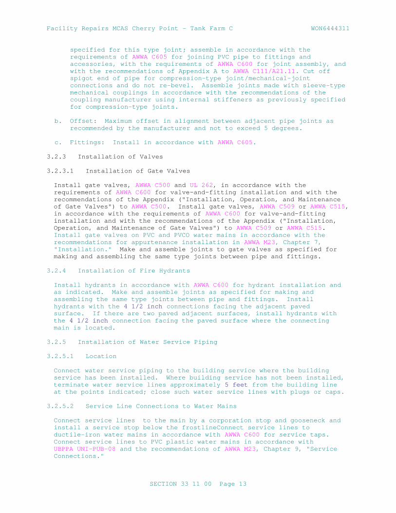
Facility Repairs MCAS Cherry Point - Tank Farm C WON6444311
specified for this type joint; assemble in accordance with the requirements of AWWA C605 for joining PVC pipe to fittings and accessories, with the requirements of AWWA C600 for joint assembly, and with the recommendations of Appendix A to AWWA C111/A21.11 . Cut off spigot end of pipe for compression-type joint/mechanical-joint connections and do not re-bevel. Assemble joints made with sleeve-type mechanical couplings in accordance with the recommendations of the coupling manufacturer using internal stiffeners as previously specified for compression-type joints.
b. Offset: Maximum offset in alignment between adjacent pipe joints as recommended by the manufacturer and not to exceed 5 degrees.
c. Fittings: Install in accordance with AWWA C605.
3.2.3 Installation of Valves
3.2.3.1 Installation of Gate Valves
Install gate valves, AWWA C500 and UL 262 , in accordance with the requirements of AWWA C600 for valve-and-fitting installation and with the recommendations of the Appendix ("Installation, Operation, and Maintenance of Gate Valves") to AWWA C500. Install gate valves, AWWA C509 or AWWA C515, in accordance with the requirements of AWWA C600 for valve-and-fitting installation and with the recommendations of the Appendix ("Installation, Operation, and Maintenance of Gate Valves") to AWWA C509 or AWWA C515. Install gate valves on PVC and PVCO water mains in accordance with the recommendations for appurtenance installation in AWWA M23, Chapter 7, "Installation." Make and assemble joints to gate valves as specified for making and assembling the same type joints between pipe and fittings.
3.2.4 Installation of Fire Hydrants
Install hydrants in accordance with AWWA C600 for hydrant installation and as indicated. Make and assemble joints as specified for making and assembling the same type joints between pipe and fittings. Install hydrants with the 4 1/2 inch connections facing the adjacent paved surface. If there are two paved adjacent surfaces, install hydrants with the 4 1/2 inch connection facing the paved surface where the connecting main is located.
3.2.5 Installation of Water Service Piping
3.2.5.1 Location
Connect water service piping to the building service where the building service has been installed. Where building service has not been installed, terminate water service lines approximately 5 feet from the building line at the points indicated; close such water service lines with plugs or caps.
3.2.5.2 Service Line Connections to Water Mains
Connect service lines to the main by a corporation stop and gooseneck and install a service stop below the frostlineConnect service lines to ductile-iron water mains in accordance with AWWA C600 for service taps. Connect service lines to PVC plastic water mains in accordance with UBPPA UNI-PUB-08 and the recommendations of AWWA M23, Chapter 9, "Service Connections."
SECTION 33 11 00 Page 13

Facility Repairs MCAS Cherry Point - Tank Farm C WON6444311
3.2.6 Disinfection
Prior to disinfection, provide disinfection procedures , proposed neutralization and disposal methods of waste water from disinfection procedures as part of the disinfection submittal. Disinfect new water piping and existing water piping affected by Contractor's operations in accordance with AWWA C651. Fill piping systems with solution containing minimum of 50 parts per million of available chlorine and allow solution to stand for minimum of 24 hours. Flush solution from the systems with domestic water until maximum residual chlorine content is within the range of 0.2 and 0.5 parts per million, or the residual chlorine content of domestic water supply. Obtain at least two consecutive bacteriological samples from new water piping. Analyze samples by a certified laboratory, and submit the results of the bacteriological samples . Obtain approval by the Contracting Officer prior to the new water piping being placed into service.
3.3 FIELD QUALITY CONTROL
3.3.1 Field Tests and Inspections
Notify the Contracting Officer a minimum of five days in advance of hydrostatic testing. Coordinate the proposed method for disposal of waste water from hydrostatic testing. Perform field tests, and provide labor, equipment, and incidentals required for testing. Provide documentation that all items of work have been constructed in accordance with the Contract documents. Do not begin testing on any section of a pipeline where concrete thrust blocks have been provided until at least five days after placing of the concrete.
3.3.2 Testing Procedure
3.3.2.1 Hydrostatic Testing
Test the water system in accordance with the applicable specified standard. Where water mains provide fire service, test in accordance with the special testing requirements given in the paragraph SPECIAL TESTING REQUIREMENTS FOR FIRE SERVICE. Test ductile-iron water mains in accordance with the requirements of AWWA C600 for hydrostatic testing. The amount of leakage on ductile-iron pipelines with mechanical-joints is not to exceed the amounts given in AWWA C600; no leakage will be allowed at joints made by any other methods. Test PVC and PVCO plastic water systems made with PVC pipe in accordance with the requirements of AWWA C605 for pressure and leakage tests. The amount of leakage on pipelines made of PVC plastic water main pipe is not to exceed the amounts given in AWWA C605, except that at joints made with sleeve-type mechanical couplings, no leakage will be allowed. Test concrete water mains in accordance with the recommendations in AWWA M9, "Hydrostatic Testing and Disinfection of Mains." The amount of leakage on concrete pipelines is not to exceed 20 gallons per 24 hours per inch of pipe diameter per mile of pipeline. Test steel water mains in accordance with applicable requirements of AWWA C600 for hydrostatic testing. The amount of leakage on steel pipelines with rubber-gasketed bell-and-spigot joints is not to exceed 20 gallons per 24 hours per inch of pipe diameter per mile of pipeline; no leakage will be allowed at joints made by any other method. Repair of welded joints to stop leakage is to be done by welding only. Test water service lines in accordance with requirements of AWWA C600 for hydrostatic testing. No leakage will be allowed at plastic pipe joints .
SECTION 33 11 00 Page 14

Facility Repairs MCAS Cherry Point - Tank Farm C WON6444311
3.3.2.2 Leakage Testing
For leakage test, use a hydrostatic pressure not less than the maximum working pressure of the system. Leakage test may be performed at the same time and at the same test pressure as the pressure test.
For PE perform leak testing in acordance with ASTM F2164.
3.3.3 Special Testing Requirements for Fire ServiceTest water mains and water service lines providing fire service or water and fire service in accordance with NFPA 24 . The additional water added to the system must not exceed the limits given in NFPA 24
3.3.4 Tracer Wire Continuity
Test tracer wire for continuity after service connections have been completed and prior to final pavement or restoration. Verify that tracer wire is locatable with electronic utility locating equipment. Repair breaks or separations and re-test for continuity.
3.4 CLEANUP
Upon completion of the installation of water lines and appurtenances, remove all debris and surplus materials resulting from the work.
-- End of Section --
SECTION 33 11 00 Page 15


Facility Repairs MCAS Cherry Point - Tank Farm C WON6444311
SECTION 33 40 00
STORM DRAINAGE UTILITIES02/10
PART 1 GENERAL
1.1 MEASUREMENT AND PAYMENT
1.2 REFERENCES
The publications listed below form a part of this specification to the extent referenced. The publications are referred to within the text by the basic designation only.
AMERICAN ASSOCIATION OF STATE HIGHWAY AND TRANSPORTATION OFFICIALS (AASHTO)
AASHTO M 167M/M 167 (2014) Standard Specification for Corrugated Steel Structural Plate, Zinc-Coated, for Field-Bolted Pipe, Pipe-Arches, and Arches
AASHTO M 219 (1992; R 2012) Standard Specification for Corrugated Aluminum Alloy Structural Plate for Field-Bolted Pipe, Pipe-Arches, and Arches
AASHTO M 243 (1996; R 2012) Standard Specification for Field-Applied Coating of Corrugated Metal Structural Plate for Pipe, Pipe-Arches, and Arches
ASTM INTERNATIONAL (ASTM)
ASTM A123/A123M (2013) Standard Specification for Zinc (Hot-Dip Galvanized) Coatings on Iron and Steel Products
ASTM A48/A48M (2003; R 2012) Standard Specification for Gray Iron Castings
ASTM A536 (1984; R 2014) Standard Specification for Ductile Iron Castings
ASTM A746 (2009; R 2014) Standard Specification for Ductile Iron Gravity Sewer Pipe
ASTM B26/B26M (2014; E 2015) Standard Specification for Aluminum-Alloy Sand Castings
ASTM C1103 (2014) Standard Practice for Joint Acceptance Testing of Installed Precast Concrete Pipe Sewer Lines
ASTM C1433 (2016a) Standard Specification for Precast Reinforced Concrete Box Sections for
SECTION 33 40 00 Page 1
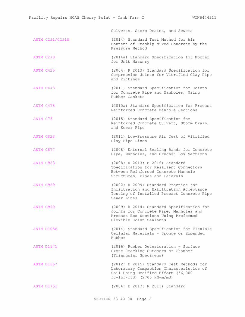
Facility Repairs MCAS Cherry Point - Tank Farm C WON6444311
Culverts, Storm Drains, and Sewers
ASTM C231/C231M (2014) Standard Test Method for Air Content of Freshly Mixed Concrete by the Pressure Method
ASTM C270 (2014a) Standard Specification for Mortar for Unit Masonry
ASTM C425 (2004; R 2013) Standard Specification for Compression Joints for Vitrified Clay Pipe and Fittings
ASTM C443 (2011) Standard Specification for Joints for Concrete Pipe and Manholes, Using Rubber Gaskets
ASTM C478 (2015a) Standard Specification for Precast Reinforced Concrete Manhole Sections
ASTM C76 (2015) Standard Specification for Reinforced Concrete Culvert, Storm Drain, and Sewer Pipe
ASTM C828 (2011) Low-Pressure Air Test of Vitrified Clay Pipe Lines
ASTM C877 (2008) External Sealing Bands for Concrete Pipe, Manholes, and Precast Box Sections
ASTM C923 (2008; R 2013; E 2016) Standard Specification for Resilient Connectors Between Reinforced Concrete Manhole Structures, Pipes and Laterals
ASTM C969 (2002; R 2009) Standard Practice for Infiltration and Exfiltration Acceptance Testing of Installed Precast Concrete Pipe Sewer Lines
ASTM C990 (2009; R 2014) Standard Specification for Joints for Concrete Pipe, Manholes and Precast Box Sections Using Preformed Flexible Joint Sealants
ASTM D1056 (2014) Standard Specification for Flexible Cellular Materials - Sponge or Expanded Rubber
ASTM D1171 (2016) Rubber Deterioration - Surface Ozone Cracking Outdoors or Chamber (Triangular Specimens)
ASTM D1557 (2012; E 2015) Standard Test Methods for Laboratory Compaction Characteristics of Soil Using Modified Effort (56,000 ft-lbf/ft3) (2700 kN-m/m3)
ASTM D1751 (2004; E 2013; R 2013) Standard
SECTION 33 40 00 Page 2

Facility Repairs MCAS Cherry Point - Tank Farm C WON6444311
Specification for Preformed Expansion Joint Filler for Concrete Paving and Structural Construction (Nonextruding and Resilient Bituminous Types)
ASTM D1752 (2004a; R 2013) Standard Specification for Preformed Sponge Rubber Cork and Recycled PVC Expansion
ASTM D2167 (2015) Density and Unit Weight of Soil in Place by the Rubber Balloon Method
ASTM D3212 (2007; R 2013) Standard Specification for Joints for Drain and Sewer Plastic Pipes Using Flexible Elastomeric Seals
ASTM D6938 (2015) Standard Test Method for In-Place Density and Water Content of Soil and Soil-Aggregate by Nuclear Methods (Shallow Depth)
ASTM F1417 (2011a) Standard Test Method for Installation Acceptance of Plastic Gravity Sewer Lines Using Low Pressure Air
1.3 SUBMITTALS
Government approval is required for submittals with a "G" designation; submittals not having a "G" designation are for Contractor Quality Control approval. Submit the following in accordance with Section 01 33 00 SUBMITTAL PROCEDURES:
SD-03 Product Data
Containment Valves
Placing Pipe
Submit printed copies of the manufacturer's recommendations for installation procedures of the material being placed, prior to installation.
SD-04 Samples
Pipe for Culverts and Storm Drains
SD-07 Certificates
Pipeline Testing
Hydrostatic Test on Watertight Joints
Determination of Density
Frame and Cover for Gratings
SECTION 33 40 00 Page 3

Facility Repairs MCAS Cherry Point - Tank Farm C WON6444311
1.4 DELIVERY, STORAGE, AND HANDLING
1.4.1 Delivery and Storage
Materials delivered to site shall be inspected for damage, unloaded, and stored with a minimum of handling. Materials shall not be stored directly on the ground. The inside of pipes and fittings shall be kept free of dirt and debris. Before, during, and after installation, plastic pipe and fittings shall be protected from any environment that would result in damage or deterioration to the material. Keep a copy of the manufacturer's instructions available at the construction site at all times and follow these instructions unless directed otherwise by the Contracting Officer. Solvents, solvent compounds, lubricants, elastomeric gaskets, and any similar materials required to install plastic pipe shall be stored in accordance with the manufacturer's recommendations and shall be discarded if the storage period exceeds the recommended shelf life. Solvents in use shall be discarded when the recommended pot life is exceeded.
1.4.2 Handling
Materials shall be handled in a manner that ensures delivery to the trench in sound, undamaged condition. Pipe shall be carried to the trench, not dragged.
PART 2 PRODUCTS
2.1 PIPE FOR CULVERTS AND STORM DRAINS
Pipe for culverts and storm drains shall be of the sizes indicated and shall conform to the requirements specified.
2.1.1 Concrete Pipe
Manufactured in accordance with and conforming to ASTM C76, Class V.
2.1.2 Structural Plate, Steel Pipe, Pipe Arches and Arches
Assembled with galvanized steel nuts and bolts, from galvanized corrugated steel plates conforming to AASHTO M 167M/M 167 . Pipe coating, when required, shall conform to the requirements of AASHTO M 243. Thickness of plates shall be as indicated.
2.1.3 Structural Plate, Aluminum Pipe, Pipe Arches and Arches
Assembled with either aluminum alloy, aluminum coated steel, stainless steel or zinc coated steel nuts and bolts. Nuts and bolts, and aluminum alloy plates shall conform to AASHTO M 219. Pipe coating, when required, shall conform to the requirements of AASHTO M 243. Thickness of plates shall be as indicated.
2.1.4 Ductile Iron Culvert Pipe
ASTM A746 . 2.2 DRAINAGE STRUCTURES
2.2.1 Precast Reinforced Concrete Box
Manufactured in accordance with and conforming to ASTM C1433.
SECTION 33 40 00 Page 4

Facility Repairs MCAS Cherry Point - Tank Farm C WON6444311
2.3 MISCELLANEOUS MATERIALS
2.3.1 Concrete
Unless otherwise specified, concrete and reinforced concrete shall conform to the requirements for 4000 psi concrete under Section 03 30 00 CAST-IN-PLACE CONCRETE. The concrete mixture shall have air content by volume of concrete, based on measurements made immediately after discharge from the mixer, of 5 to 7 percent when maximum size of coarse aggregate exceeds 1-1/2 inches . Air content shall be determined in accordance with ASTM C231/C231M. The concrete covering over steel reinforcing shall not be less than 1 inch thick for covers and not less than 1-1/2 inches thick for walls and flooring. Concrete covering deposited directly against the ground shall have a thickness of at least 3 inches between steel and ground. Expansion-joint filler material shall conform to ASTM D1751, or ASTM D1752, or shall be resin-impregnated fiberboard conforming to the physical requirements of ASTM D1752.
2.3.2 Mortar
Mortar for pipe joints, connections to other drainage structures, and brick or block construction shall conform to ASTM C270, Type M, except that the maximum placement time shall be 1 hour. The quantity of water in the mixture shall be sufficient to produce a stiff workable mortar. Water shall be clean and free of harmful acids, alkalis, and organic impurities. The mortar shall be used within 30 minutes after the ingredients are mixed with water. The inside of the joint shall be wiped clean and finished smooth. The mortar head on the outside shall be protected from air and sun with a proper covering until satisfactorily cured.
2.3.3 Precast Reinforced Concrete Manholes
Conform to ASTM C478. Joints between precast concrete risers and tops shall be full-bedded in cement mortar and shall be smoothed to a uniform surface on both interior and exterior of the structure.
2.3.4 Frame and Cover for Gratings
Submit certification on the ability of frame and cover or gratings to carry the imposed live load. Frame and cover for gratings shall be cast gray iron, ASTM A48/A48M, Class 35B; cast ductile iron, ASTM A536, Grade 65-45-12; or cast aluminum, ASTM B26/B26M, Alloy 356.OT6. Weight, shape, size, and waterway openings for grates and curb inlets shall be as indicated on the plans. The word "Storm Sewer" shall be stamped or cast into covers so that it is plainly visible.
2.3.5 Joints
2.3.5.1 Flexible Watertight Joints
a. Materials: Flexible watertight joints shall be made with plastic or rubber-type gaskets for concrete pipe and with factory-fabricated resilient materials for clay pipe. The design of joints and the physical requirements for preformed flexible joint sealants shall conform to ASTM C990, and rubber-type gaskets shall conform to ASTM C443. Factory-fabricated resilient joint materials shall conform to ASTM C425. Gaskets shall have not more than one factory-fabricated splice, except that two factory-fabricated splices of the rubber-type gasket are permitted if the nominal diameter of the pipe being gasketed exceeds 54
SECTION 33 40 00 Page 5

Facility Repairs MCAS Cherry Point - Tank Farm C WON6444311
inches .
b. Test Requirements: Watertight joints shall be tested and shall meet test requirements of paragraph HYDROSTATIC TEST ON WATERTIGHT JOINTS. Rubber gaskets shall comply with the oil resistant gasket requirements of ASTM C443. Certified copies of test results shall be delivered to the Contracting Officer before gaskets or jointing materials are installed. Alternate types of watertight joint may be furnished, if specifically approved.
2.3.5.2 External Sealing Bands
Requirements for external sealing bands shall conform to ASTM C877.
2.3.5.3 Flexible Watertight, Gasketed Joints
a. Gaskets: When infiltration or exfiltration is a concern for pipe lines, the couplings may be required to have gaskets. The closed-cell expanded rubber gaskets shall be a continuous band approximately 7 inches wide and approximately 3/8 inch thick, meeting the requirements of ASTM D1056, Type 2 B3, and shall have a quality retention rating of not less than 70 percent when tested for weather resistance by ozone chamber exposure, Method B of ASTM D1171. Rubber O-ring gaskets shall be 13/16 inch in diameter for pipe diameters of 36 inches or smaller and 7/8 inch in diameter for larger pipe having 1/2 inch deep end corrugation. Rubber O-ring gaskets shall be 1-3/8 inches in diameter for pipe having 1 inch deep end corrugations. O-rings shall meet the requirements of ASTM C990 or ASTM C443. Preformed flexible joint sealants shall conform to ASTM C990, Type B.
b. Connecting Bands: Connecting bands shall be of the type, size and sheet thickness of band, and the size of angles, bolts, rods and lugs as indicated or where not indicated as specified in the applicable standards or specifications for the pipe. Exterior rivet heads in the longitudinal seam under the connecting band shall be countersunk or the rivets shall be omitted and the seam welded. Watertight joints shall be tested and shall meet the test requirements of paragraph HYDROSTATIC TEST ON WATERTIGHT JOINTS.
2.3.5.4 Ductile Iron Pipe
Couplings and fittings shall be as recommended by the pipe manufacturer. Ductile iron gaskets and fittings shall be petroleum resistant.
2.4 STEEL LADDER
Steel ladder shall be provided where the depth of the storm drainage structure exceeds 12 feet . These ladders shall be not less than 16 inches in width, with 3/4 inch diameter rungs spaced 12 inches apart. The two stringers shall be a minimum 3/8 inch thick and 2-1/2 inches wide. Ladders and inserts shall be galvanized after fabrication in conformance with ASTM A123/A123M .
2.5 RESILIENT CONNECTORS
Flexible, watertight connectors used for connecting pipe to manholes and inlets shall conform to ASTM C923.
SECTION 33 40 00 Page 6

Facility Repairs MCAS Cherry Point - Tank Farm C WON6444311
2.6 HYDROSTATIC TEST ON WATERTIGHT JOINTS
2.6.1 Concrete, Clay, PVC, PE, SRPE and PP Pipe
A hydrostatic test shall be made on the watertight joint types as proposed. Only one sample joint of each type needs testing; however, if the sample joint fails because of faulty design or workmanship, an additional sample joint may be tested. During the test period, gaskets or other jointing material shall be protected from extreme temperatures which might adversely affect the performance of such materials. Performance requirements for joints in reinforced and nonreinforced concrete pipe shall conform to ASTM C990 or ASTM C443. Test requirements for joints in clay pipe shall conform to ASTM C425. Test requirements for joints in PVC, PE, and PP plastic pipe shall conform to ASTM D3212.
2.7 CONTAINMENT VALVES
Containment valves shall be 100 % port eccentric plug valves, which conform to AWWA C517. Seals and wedge shall be nitrile rubber or other material recommended by the manufacturer for jet fuel resistance. Valves shall have a sealed extended bonnet to a geared actuator. Actuator shall be equipped with an open/closed indicator and be lockable in the closed position.
PART 3 EXECUTION
3.1 EXCAVATION FOR PIPE CULVERTS, STORM DRAINS, AND DRAINAGE STRUCTURES
Excavation of trenches, and for appurtenances and backfilling for culverts and storm drains, shall be in accordance with the applicable portions of Section 31 23 00.00 20 EXCAVATION AND FILL and the requirements specified below.
3.1.1 Trenching
The width of trenches at any point below the top of the pipe shall be not greater than the outside diameter of the pipe plus 8 inches to permit satisfactory jointing and thorough tamping of the bedding material under and around the pipe. Sheeting and bracing, where required, shall be placed within the trench width as specified, without any overexcavation. Where trench widths are exceeded, redesign with a resultant increase in cost of stronger pipe or special installation procedures will be necessary. Cost of this redesign and increased cost of pipe or installation shall be borne by the Contractor without additional cost to the Government.
3.1.2 Removal of Rock
Rock in either ledge or boulder formation shall be replaced with suitable materials to provide a compacted earth cushion having a thickness between unremoved rock and the pipe of at least 8 inches or 1/2 inch for each foot of fill over the top of the pipe, whichever is greater, but not more than three-fourths the nominal diameter of the pipe. Where bell-and-spigot pipe is used, the cushion shall be maintained under the bell as well as under the straight portion of the pipe. Rock excavation shall be as specified and defined in Section 31 23 00.00 20 EXCAVATION AND FILL .
3.1.3 Removal of Unstable Material
Where wet or otherwise unstable soil incapable of properly supporting the pipe, as determined by the Contracting Officer, is unexpectedly encountered
SECTION 33 40 00 Page 7

Facility Repairs MCAS Cherry Point - Tank Farm C WON6444311
in the bottom of a trench, such material shall be removed to the depth required and replaced to the proper grade with select granular material, compacted as provided in paragraph BACKFILLING. When removal of unstable material is due to the fault or neglect of the Contractor while performing shoring and sheeting, water removal, or other specified requirements, such removal and replacement shall be performed at no additional cost to the Government.
3.2 BEDDING
The bedding surface for the pipe shall provide a firm foundation of uniform density throughout the entire length of the pipe.
3.2.1 Concrete Pipe Requirements
When no bedding class is specified or detailed on the drawings, concrete pipe shall be bedded in granular material minimum 4 inch in depth in trenches with soil foundation. Depth of granular bedding in trenches with rock foundation shall be 1/2 inch in depth per foot of depth of fill, minimum depth of bedding shall be 8 inch up to maximum depth of 24 inches . The middle third of the granular bedding shall be loosely placed. Bell holes and depressions for joints shall be removed and formed so entire barrel of pipe is uniformly supported. The bell hole and depressions for the joints shall be not more than the length, depth, and width required for properly making the particular type of joint.
3.3 PLACING PIPE
Note post installation requirements of paragraph DEFLECTION TESTING in PART 3 of this specification for all pipe products including deflection testing requirements for flexible pipe.
3.3.1 Concrete, Clay, PVC, Ribbed PVC, Ductile Iron and Cast-Iron Pipe
Laying shall proceed upgrade with spigot ends of bell-and-spigot pipe and tongue ends of tongue-and-groove pipe pointing in the direction of the flow.
3.4 JOINTING
3.4.1 Concrete and Clay Pipe
3.4.1.1 Cement-Mortar Bell-and-Spigot Joint
The first pipe shall be bedded to the established grade line, with the bell end placed upstream. The interior surface of the bell shall be thoroughly cleaned with a wet brush and the lower portion of the bell filled with mortar as required to bring inner surfaces of abutting pipes flush and even. The spigot end of each subsequent pipe shall be cleaned with a wet brush and uniformly matched into a bell so that sections are closely fitted. After each section is laid, the remainder of the joint shall be filled with mortar, and a bead shall be formed around the outside of the joint with sufficient additional mortar. If mortar is not sufficiently stiff to prevent appreciable slump before setting, the outside of the joint shall be wrapped or bandaged with cheesecloth to hold mortar in place.
3.4.1.2 Cement-Mortar Tongue-and-Groove Joint
The first pipe shall be bedded carefully to the established grade line with
SECTION 33 40 00 Page 8

Facility Repairs MCAS Cherry Point - Tank Farm C WON6444311
the groove upstream. A shallow excavation shall be made underneath the pipe at the joint and filled with mortar to provide a bed for the pipe. The grooved end of the first pipe shall be thoroughly cleaned with a wet brush, and a layer of soft mortar applied to the lower half of the groove. The tongue of the second pipe shall be cleaned with a wet brush; while in horizontal position, a layer of soft mortar shall be applied to the upper half of the tongue. The tongue end of the second pipe shall be inserted in the grooved end of the first pipe until mortar is squeezed out on interior and exterior surfaces. Sufficient mortar shall be used to fill the joint completely and to form a bead on the outside.
3.4.1.3 Flexible Watertight Joints
Gaskets and jointing materials shall be as recommended by the particular manufacturer in regard to use of lubricants, cements, adhesives, and other special installation requirements. Surfaces to receive lubricants, cements, or adhesives shall be clean and dry. Gaskets and jointing materials shall be affixed to the pipe not more than 24 hours prior to the installation of the pipe, and shall be protected from the sun, blowing dust, and other deleterious agents at all times. Gaskets and jointing materials shall be inspected before installing the pipe; any loose or improperly affixed gaskets and jointing materials shall be removed and replaced. The pipe shall be aligned with the previously installed pipe, and the joint pushed home. If, while the joint is being made the gasket becomes visibly dislocated the pipe shall be removed and the joint remade.
3.5 DRAINAGE STRUCTURES
3.5.1 Manholes and Inlets
Construction shall be of reinforced concrete, plain concrete, brick, precast reinforced concrete, precast concrete segmental blocks, prefabricated corrugated metal, or bituminous coated corrugated metal; complete with frames and covers or gratings; and with fixed galvanized steel ladders where indicated. Pipe studs and junction chambers of prefabricated corrugated metal manholes shall be fully bituminous-coated and paved when the connecting branch lines are so treated. Pipe connections to concrete manholes and inlets shall be made with flexible, watertight connectors.
3.6 STEEL LADDER INSTALLATION
Ladder shall be adequately anchored to the wall by means of steel inserts spaced not more than 6 feet vertically, and shall be installed to provide at least 6 inches of space between the wall and the rungs. The wall along the line of the ladder shall be vertical for its entire length.
3.7 BACKFILLING
3.7.1 Backfilling Pipe in Trenches
After the pipe has been properly bedded, selected material from excavation or borrow, at a moisture content that will facilitate compaction, shall be placed along both sides of pipe in layers not exceeding 6 inches in compacted depth. The backfill shall be brought up evenly on both sides of pipe for the full length of pipe. The fill shall be thoroughly compacted under the haunches of the pipe. Each layer shall be thoroughly compacted with mechanical tampers or rammers. This method of filling and compacting shall continue until the fill has reached an elevation equal to the
SECTION 33 40 00 Page 9

Facility Repairs MCAS Cherry Point - Tank Farm C WON6444311
midpoint (spring line) of RCP or has reached an elevation of at least 12 inches above the top of the pipe for flexible pipe. The remainder of the trench shall be backfilled and compacted by spreading and rolling or compacted by mechanical rammers or tampers in layers not exceeding 6 inches . Tests for density shall be made as necessary to ensure conformance to the compaction requirements specified below. Where it is necessary, in the opinion of the Contracting Officer, that sheeting or portions of bracing used be left in place, the contract will be adjusted accordingly. Untreated sheeting shall not be left in place beneath structures or pavements.
3.7.2 Backfilling Pipe in Fill Sections
For pipe placed in fill sections, backfill material and the placement and compaction procedures shall be as specified below. The fill material shall be uniformly spread in layers longitudinally on both sides of the pipe, not exceeding 6 inches in compacted depth, and shall be compacted by rolling parallel with pipe or by mechanical tamping or ramming. Prior to commencing normal filling operations, the crown width of the fill at a height of 12 inches above the top of the pipe shall extend a distance of not less than twice the outside pipe diameter on each side of the pipe or 12 feet , whichever is less. After the backfill has reached at least 12 inches above the top of the pipe, the remainder of the fill shall be placed and thoroughly compacted in layers not exceeding 6 inches . Use select granular material for this entire region of backfill for flexible pipe installations.
3.7.3 Movement of Construction Machinery
When compacting by rolling or operating heavy equipment parallel with the pipe, displacement of or injury to the pipe shall be avoided. Movement of construction machinery over a culvert or storm drain at any stage of construction shall be at the Contractor's risk. Any damaged pipe shall be repaired or replaced.
3.7.4 Compaction
3.7.4.1 General Requirements
Cohesionless materials include gravels, gravel-sand mixtures, sands, and gravelly sands. Cohesive materials include clayey and silty gravels, gravel-silt mixtures, clayey and silty sands, sand-clay mixtures, clays, silts, and very fine sands. When results of compaction tests for moisture-density relations are recorded on graphs, cohesionless soils will show straight lines or reverse-shaped moisture-density curves, and cohesive soils will show normal moisture-density curves.
3.7.4.2 Minimum Density
Backfill over and around the pipe and backfill around and adjacent to drainage structures shall be compacted at the approved moisture content to the following applicable minimum density, which will be determined as specified below.
a. Under airfield and heliport pavements, paved roads, streets, parking areas, and similar-use pavements including adjacent shoulder areas, the density shall be not less than 90 percent of maximum density for cohesive material and 95 percent of maximum density for cohesionless material, up to the elevation where requirements for pavement subgrade
SECTION 33 40 00 Page 10

Facility Repairs MCAS Cherry Point - Tank Farm C WON6444311
materials and compaction shall control.
b. Under unpaved or turfed traffic areas, density shall not be less than 90 percent of maximum density for cohesive material and 95 percent of maximum density for cohesionless material.
c. Under nontraffic areas, density shall be not less than that of the surrounding material.
3.7.5 Determination of Density
Testing is the responsibility of the Contractor and performed at no additional cost to the Government. Testing shall be performed by an approved commercial testing laboratory or by the Contractor subject to approval. Tests shall be performed in sufficient number to ensure that specified density is being obtained. Laboratory tests for moisture-density relations shall be made in accordance with ASTM D1557 except that mechanical tampers may be used provided the results are correlated with those obtained with the specified hand tamper. Field density tests shall be determined in accordance with ASTM D2167 or ASTM D6938. When ASTM D6938 is used, the calibration curves shall be checked and adjusted, if necessary, using the sand cone method as described in paragraph Calibration of the referenced publications. ASTM D6938 results in a wet unit weight of soil and ASTM D6938 shall be used to determine the moisture content of the soil. The calibration curves furnished with the moisture gauges shall be checked along with density calibration checks as described in ASTM D6938. Test results shall be furnished the Contracting Officer. The calibration checks of both the density and moisture gauges shall be made at the beginning of a job on each different type of material encountered and at intervals as directed.
3.8 PIPELINE TESTING
3.8.1 Leakage Tests
Lines shall be tested for leakage by low pressure air or water testing or exfiltration tests, as appropriate. Low pressure air testing for vitrified clay pipes shall conform to ASTM C828. Low pressure air testing for concrete pipes shall conform to ASTM C969. Low pressure air testing for plastic pipe shall conform to ASTM F1417. Low pressure air testing procedures for other pipe materials shall use the pressures and testing times prescribed in ASTM C828 or ASTM C969, after consultation with the pipe manufacturer. Testing of individual joints for leakage by low pressure air or water shall conform to ASTM C1103. Prior to exfiltration tests, the trench shall be backfilled up to at least the lower half of the pipe. If required, sufficient additional backfill shall be placed to prevent pipe movement during testing, leaving the joints uncovered to permit inspection. Visible leaks encountered shall be corrected regardless of leakage test results. When the water table is 2 feet or more above the top of the pipe at the upper end of the pipeline section to be tested, infiltration shall be measured using a suitable weir or other device acceptable to the Contracting Officer. An exfiltration test shall be made by filling the line to be tested with water so that a head of at least 2 feet is provided above both the water table and the top of the pipe at the upper end of the pipeline to be tested. The filled line shall be allowed to stand until the pipe has reached its maximum absorption, but not less than 4 hours. After absorption, the head shall be reestablished. The amount of water required to maintain this water level during a 2-hour test period shall be measured. Leakage as measured by the exfiltration test
SECTION 33 40 00 Page 11

Facility Repairs MCAS Cherry Point - Tank Farm C WON6444311
shall not exceed 0.2 gallons per inch in diameter per 100 feet of pipeline per hour. When leakage exceeds the maximum amount specified, satisfactory correction shall be made and retesting accomplished.
3.8.2 Post-Installation Inspection
Check each reinforced concrete pipe installation for joint separations, soil migration through the joint, cracks greater than 0.01 inches , settlement and alignment. Check each flexible pipe (HDPE, PVC, CMP, PP) for rips, tears, joint separations, soil migration through the joint, cracks, localized bucking, bulges, settlement and alignment.
a. Replace pipes having cracks greater than 0.1 inches in width or deflection greater than 5 percent deflection. An engineer shall evaluate all pipes with cracks greater than 0.01 inches but less than 0.10 inches to determine if any remediation or repair is required. RCP with crack width less than 0.10 inches and located in a non-corrosive environment (pH 5.5) are generally acceptable. Repair or replace any pipe with crack exhibiting displacement across the crack, exhibiting bulges, creases, tears, spalls, or delamination.
b. Reports: The deflection results and final post installation inspection report shall include: a copy of all video taken, pipe location identification, equipment used for inspection, inspector name, deviation from design, grade, deviation from line, deflection and deformation of flexible pipe systems, inspector notes, condition of joints, condition of pipe wall (e.g. distress, cracking, wall damage dents, bulges, creases, tears, holes, etc.).
3.9 FIELD PAINTING
After installation, clean cast-iron frames, covers, gratings, and steps not buried in masonry or concrete to bare metal of mortar, rust, grease, dirt, and other deleterious materials and apply a coat of bituminous paint. Do not paint surfaces subject to abrasion.
-- End of Section --
SECTION 33 40 00 Page 12
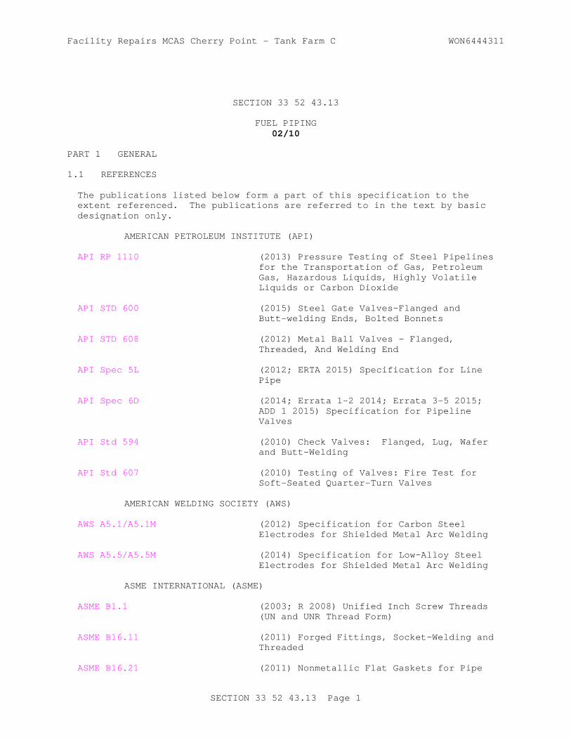
Facility Repairs MCAS Cherry Point - Tank Farm C WON6444311
SECTION 33 52 43.13
FUEL PIPING02/10
PART 1 GENERAL
1.1 REFERENCES
The publications listed below form a part of this specification to the extent referenced. The publications are referred to in the text by basic designation only.
AMERICAN PETROLEUM INSTITUTE (API)
API RP 1110 (2013) Pressure Testing of Steel Pipelines for the Transportation of Gas, Petroleum Gas, Hazardous Liquids, Highly Volatile Liquids or Carbon Dioxide
API STD 600 (2015) Steel Gate Valves-Flanged and Butt-welding Ends, Bolted Bonnets
API STD 608 (2012) Metal Ball Valves - Flanged, Threaded, And Welding End
API Spec 5L (2012; ERTA 2015) Specification for Line Pipe
API Spec 6D (2014; Errata 1-2 2014; Errata 3-5 2015; ADD 1 2015) Specification for Pipeline Valves
API Std 594 (2010) Check Valves: Flanged, Lug, Wafer and Butt-Welding
API Std 607 (2010) Testing of Valves: Fire Test for Soft-Seated Quarter-Turn Valves
AMERICAN WELDING SOCIETY (AWS)
AWS A5.1/A5.1M (2012) Specification for Carbon Steel Electrodes for Shielded Metal Arc Welding
AWS A5.5/A5.5M (2014) Specification for Low-Alloy Steel Electrodes for Shielded Metal Arc Welding
ASME INTERNATIONAL (ASME)
ASME B1.1 (2003; R 2008) Unified Inch Screw Threads (UN and UNR Thread Form)
ASME B16.11 (2011) Forged Fittings, Socket-Welding and Threaded
ASME B16.21 (2011) Nonmetallic Flat Gaskets for Pipe
SECTION 33 52 43.13 Page 1

Facility Repairs MCAS Cherry Point - Tank Farm C WON6444311
Flanges
ASME B16.34 (2013) Valves - Flanged, Threaded and Welding End
ASME B16.5 (2013) Pipe Flanges and Flanged Fittings: NPS 1/2 Through NPS 24 Metric/Inch Standard
ASME B16.9 (2012) Standard for Factory-Made Wrought Steel Buttwelding Fittings
ASME B18.2.1 (2012; Errata 2013) Square and Hex Bolts and Screws (Inch Series)
ASME B18.2.2 (2010) Nuts for General Applications: Machine Screw Nuts, Hex, Square, Hex Flange, and Coupling Nuts (Inch Series)
ASME B31.3 (2014) Process Piping
ASME BPVC SEC VIII D1 (2010) BPVC Section VIII-Rules for Construction of Pressure Vessels Division 1
ASTM INTERNATIONAL (ASTM)
ASTM A105/A105M (2014) Standard Specification for Carbon Steel Forgings for Piping Applications
ASTM A182/A182M (2016) Standard Specification for Forged or Rolled Alloy-Steel Pipe Flanges, Forged Fittings, and Valves and Parts for High-Temperature Service
ASTM A193/A193M (2016) Standard Specification for Alloy-Steel and Stainless Steel Bolting Materials for High-Temperature Service and Other Special Purpose Applications
ASTM A194/A194M (2016) Standard Specification for Carbon and Alloy Steel Nuts for Bolts for High-Pressure or High-Temperature Service, or Both
ASTM A234/A234M (2013; E 2014) Standard Specification for Piping Fittings of Wrought Carbon Steel and Alloy Steel for Moderate and High Temperature Service
ASTM A403/A403M (2016) Standard Specification for Wrought Austenitic Stainless Steel Piping Fittings
ASTM A436 (1984; R 2011) Standard Specification for Austenitic Gray Iron Castings
ASTM A53/A53M (2012) Standard Specification for Pipe, Steel, Black and Hot-Dipped, Zinc-Coated, Welded and Seamless
ASTM A961/A961M (2014) Standard Specification for Common
SECTION 33 52 43.13 Page 2

Facility Repairs MCAS Cherry Point - Tank Farm C WON6444311
Requirements for Steel Flanges, Forged Fittings, Valves, and Parts for Piping Applications
ASTM F436 (2011) Hardened Steel Washers
MANUFACTURERS STANDARDIZATION SOCIETY OF THE VALVE AND FITTINGS INDUSTRY (MSS)
MSS SP-58 (1993; Reaffirmed 2010) Pipe Hangers and Supports - Materials, Design and Manufacture, Selection, Application, and Installation
NATIONAL FIRE PROTECTION ASSOCIATION (NFPA)
NFPA 30 (2015) Flammable and Combustible Liquids Code
SOCIETY OF AUTOMOTIVE ENGINEERS INTERNATIONAL (SAE)
SAE J514 (2012) Hydraulic Tube Fittings
U.S. DEPARTMENT OF DEFENSE (DOD)
MIL-STD-161 (2005; Rev G; Notice 1 2010) Identification Methods for Bulk Petroleum Products Systems Including Hydrocarbon Missile Fuels
1.2 ADMINISTRATIVE REQUIREMENTS
Design conditions shall be as specified in Section 33 52 43.11 AVIATION FUEL MECHANICAL EQUIPMENT. Submit a copy of welding qualified procedures, where the procedures will be used, and a list of names and identification symbols of qualified welders and welding operators. Submit Operation and Maintenance Manuals for the equipment items or systems listed below.
Manual ValvesFlexible Ball JointsSurge Suppressor Tank and ValveStrainersProtective CoatingsSample ConnectionsIsolating Gasket KitsGasketsFlexible Hoses
1.3 SUBMITTALS
Government approval is required for submittals with a "G" designation; submittals not having a "G" designation are for Contractor Quality Control approval. Submit the following in accordance with Section 01 33 00 SUBMITTAL PROCEDURES:
SD-03 Product Data
Fittings ; G
SECTION 33 52 43.13 Page 3

Facility Repairs MCAS Cherry Point - Tank Farm C WON6444311
Flexible Ball Joints ; G
Carbon Steel Piping ; G
Flexible Pipe ; G
Strainers ; G
Flexible Hoses ; G
Protective Coatings ; G
Sample Connections ; G
Isolating Gasket Kits ; G
Gaskets - Spiral Wound
Transition Sumps ; G
SD-06 Test Reports
Pneumatic Test
Hydrostatic Test
SD-07 Certificates
Welding
Fittings
Isolating Gasket Kits
Survey Final Elevations
SD-10 Operation and Maintenance Data
Operation and Maintenance Manuals ; G
1.4 QUALITY ASSURANCE
1.4.1 Welding Qualifications
Welding of fuel pipe joints shall comply with Section 33 52 90.00 20 WELDING FOR POL SERVICE PIPING.
PART 2 PRODUCTS
2.1 MATERIALS AND EQUIPMENT
Pipe and fittings in contact with fuel shall be stainless steel, interior epoxy coated carbon steel, or carbon steel as indicated on the drawings. No zinc coated metals, brass, bronze or other copper bearing alloys shall be used in contact with the fuel. All carbon steel and stainless steel underground piping shall have an exterior protective coating.
SECTION 33 52 43.13 Page 4
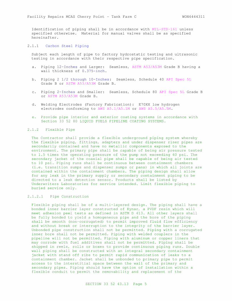
Facility Repairs MCAS Cherry Point - Tank Farm C WON6444311
Identification of piping shall be in accordance with MIL-STD-161 unless specified otherwise. Material for manual valves shall be as specified hereinafter.
2.1.1 Carbon Steel Piping
Subject each length of pipe to factory hydrostatic testing and ultrasonic testing in accordance with their respective pipe specification.
a. Piping 12-Inches and Larger: Seamless, ASTM A53/A53M Grade B having a wall thickness of 0.375-inch .
b. Piping 2 1/2 through 10-Inches : Seamless, Schedule 40 API Spec 5L Grade B or ASTM A53/A53M Grade B.
c. Piping 2-Inches and Smaller: Seamless, Schedule 80 API Spec 5L Grade B or ASTM A53/A53M Grade B.
d. Welding Electrodes (Factory Fabrication): E70XX low hydrogen electrodes conforming to AWS A5.1/A5.1M or AWS A5.5/A5.5M .
e. Provide pipe interior and exterior coating systems in accordance with Section 33 52 80 LIQUID FUELS PIPELINE COATING SYSTEMS.
2.1.2 Flexible Pipe
The Contractor shall provide a flexible underground piping system wherebythe flexible piping, fittings, adapters and under dispenser riser pipes aresecondarily contained and have no metallic components exposed to theenvironment. The primary pipe shall be capable of being air pressure testedto 1.5 times the operating pressure of the pump not exceeding 60 psi. Thesecondary jacket of the coaxial pipe shall be capable of being air testedto 10 psi. Piping runs shall be continuous between containment chambers(i.e. transition sumps and dispenser sumps or pans) in which all joints arecontained within the containment chambers. The piping design shall allowfor any leak in the primary supply or secondary containment piping to bedirected to a leak detection sensor. Products shall be listed byUnderwriters Laboratories for service intended. Limit flexible piping toburied service only.
2.1.2.1 Pipe Construction
Flexible piping shall be of a multi-layered design. The piping shall have abonded inner barrier layer constructed of Kynar, a PVDF resin which willmeet adhesion peel tests as defined in ASTM D 413. All other layers shallbe fully bonded to yield a homogeneous pipe and the bore of the pipingshall be smooth (non-corrugated) to permit improved fluid flow efficiencyand without break or interruption to the integrity of the barrier layer.Unbonded pipe construction shall not be permitted. Piping with a corrugatedinner bore shall not be permitted. Piping with welded couplers in thepipeline will not be permitted. Piping with aluminum or copper liners thatmay corrode with fuel additives shall not be permitted. Piping shall beshipped in reels, rolls or boxes to provide continuous piping runs. Doublewall piping shall be constructed with an integral secondary containmentjacket with stand off ribs to permit rapid communication of leaks to acontainment chamber. Jacket shall be unbonded to primary pipe to permitaccess to the interstitial space between the wall of the primary andsecondary pipes. Piping should have the option of installation within aflexible conduit to permit the removability and replacement of the
SECTION 33 52 43.13 Page 5

Facility Repairs MCAS Cherry Point - Tank Farm C WON6444311
piping without the need for excavating.
2.1.2.2 Fittings/Couplings Construction
Couplings shall be of stainless steel or a double wall (coaxial) glass composite thermo-plastic. Brass couplings shall not be permitted.Couplings shall be internally expanded. Stainless Steel couplings shallhave a smooth sealing face fitted with a Viton ring gasket. Coaxialcomposite fittings shall have a triple O-ring seal. Stainless steelcouplings shall have a swivel nut used to connect the pipe coupling to theswivel fittings. The pipe manufacturer shall supply the fittings, includingthe tee fittings, elbow fittings and adapters. The couplings and fittingsshall be listed by Underwriters Laboratories to UL 971. Only couplingssupplied by the pipe manufacturer will be connected to the pipe usingequipment designed specifically for connection to the pipe by themanufacturer.
2.1.2.3 Primary and Secondary Continuity
All primary and secondary piping shall be connected in such a way as topermit integrity testing of both pipes during installation, as well as atperiodic intervals. The interstitial space between the primary andsecondary pipes shall be connected using either double walled fittings or aconnector tube, which will permit access to the entire secondary systemfrom one location.
2.1.2.4 Product and Chemical Compatibility
The flexible underground piping and associated couplings, fittings andadapters shall be chemically compatible with the products to be transportedand with chemicals found naturally in the ground environment. The primaryand secondary piping shall be compatible with gasoline, alcohols,gasoline-alcohol mixtures and all EPA approved additives, including MTBE.
2.1.2.5 Resistance to Internal and External Bacteria
The flexible underground piping and associated couplings, fittings andadapters shall be resistant to internal and external attack by naturallyoccurring soil bacteria.
2.1.2.6 Corrosion Resistance
The flexible underground piping and associated couplings, fittings andadapters which come in contact with the ground environment shall be made ofnon-metallic material or encapsulated by non-metallic components whichprevent corrosion.
2.1.2.7 Structural Integrity
The flexible underground piping and associated couplings, fittings andadapters shall be designed and constructed of materials strong enough forits intended use. The flexible piping shall not collapse, crack or breakdue to ground movement or from backfill and high ground water pressures.Piping shall be able to transfer fluid up to a maximum temperature of 125degrees Fahrenheit (52 degrees Celsius). Piping shall be operational withina temperature band of minus 40C and +65C.
SECTION 33 52 43.13 Page 6

Facility Repairs MCAS Cherry Point - Tank Farm C WON6444311
2.1.2.8 Bend Radius
The double wall flexible piping shall be capable of a minimum bend radiuswithout kinking, cracking or breaking. Bend radii shall be dependent on thediameter of the pipe and should not exceed:
2.0 inch pipe - 36 inch radius
2.1.2.9 Surface Resistivity
The double wall flexible pipe shall have an inner layer electrical surfaceresistance less than 1011 Ohms.
2.1.2.10 Fluid Flow Efficiency
Both the primary inner and secondary outer pipe shall have an interiorsurface which is a smooth (non-corrugated) profile and be made of a lowfriction resistant material for improved fluid efficiency.
2.1.2.11 Operating Pressure and Vacuums
The flexible underground piping shall have a minimum five to one (5:1)safety factor from maximum operating pressure for rated pressure. 2.0 inchand 3.0 inch piping shall be rated at a maximum operating pressure of 75psi primary and 10 psi secondary.
2.1.2.12 Pipe Expansion
The primary supply pipe shall not expand more than 0.0025 percent indiameter and overall length when pressurized to 60 psi to permit accuratepressure decay readings by an in-line leak detector.
2.1.2.13 Interstitial Interconnection
All primary and secondary piping shall be connected in such a way as topermit integrity testing both during installation and at periodic intervalsin the future. Both primary and secondary piping shall remain continuousduring operation.
2.1.2.14 Transition Sumps
Chambers used for transitioning from aboveground steel pipe to undergroundflexible pipe shall be designed and constructed of materials strong enoughfor their intended use. Chambers shall not collapse, crack or break due toground movement, settling of backfill or static pressure associated withhigh ground water conditions. All chambers shall be provided with awatertight cover that does not require mechanical means to providecompression of the cover seal.
2.1.2.14.1 Chemical Resistance
All transition sumps shall be made of materials which are compatible withall EPA approved fuels and additives. Evidence shall be provided to supportthe chemical resistance of the materials for the temporary storage ofpetroleum and alcohol-based fuels as well as long term exposure to groundenvironments.
SECTION 33 52 43.13 Page 7
Facility Repairs MCAS Cherry Point - Tank Farm C WON6444311
2.1.2.14.2 Construction
Chambers shall be constructed of virgin high-grade polyethylene andmanufactured by rotational molding.
2.1.2.15 Pipe and Conduit Entry Seals
All containment chambers shall be fitted with pipe and conduit entrieswhich are semi-absorbent to ground movement and sufficiently flexible to permit angled entries up to 15 degrees off of the centerline in vertical orhorizontal direction. Seals shall be compatible with the fluids containedwithin the chamber as well as the surrounding ground environment andcapable of withstanding a static head pressure of 6 feet.
2.1.2.15.1 Construction
Seals shall be constructed of fuel compatible Buna-N rubber. Seals shall bestudded ring design with only non-metallic components exposed to theenvironment.
2.1.2.15.2 Corrosion Resistance
Pipe and conduit entry seals shall have an exterior studded compressionring encapsulated within rubber to protect it from corrosion. All studsshall be stainless steel and exposed only on the inside of the containmentchamber.
2.1.2.15.3 Angled Entries and Universal Alignment
Pipe and conduit seals shall be flexible enough to permit angled pipe orconduit entries (on two axis) into the sidewall of the containment chamber.All pipe and conduit seals shall permit angled entries up to a 15-degreeangle off the perpendicular centerline in any direction without leaking orputting undue stress on the pipe or conduit seal.
2.1.3 Protective Coatings for Aboveground Piping
Provide coating of aboveground piping, piping in pits, pipe supports, filter separators, and miscellaneous metal and equipment in accordance with Section 33 52 80 LIQUID FUELS PIPELINE COATING SYSTEM. Color of finish coat shall be white . Do not paint stainless steel or aluminum surfaces.
2.1.4 Fittings
2.1.4.1 General
Welding ells, caps, tees, reducers, etc., shall be of materials compatible for welding to the pipe line in which they are installed, and wall thickness, pressure and temperature ratings of the fittings shall be not less than the adjoining pipe line. Unless otherwise required by the conditions of installation, all elbows shall be the long radius type. Miter joints are not acceptable. Make odd angle offsets with pipe bends or elbows cut to the proper angle. Butt weld fittings shall be factory-made wrought fittings manufactured by forging or shaping. Fabricated fittings will not be permitted. Welding branch fittings shall be insert type suitable for radiographic inspections specified herein.
SECTION 33 52 43.13 Page 8
Facility Repairs MCAS Cherry Point - Tank Farm C WON6444311
2.1.4.2 Carbon Steel Fittings
a. Fittings 2.5 Inches and Larger: Butt weld, conforming to ASTM A234/A234M , grade WPB and ASME B16.9 of the same wall thickness as the adjoining pipe. All welds shall be radiographically examined throughout the entire length of each weld. Each fitting shall be subjected to the Supplementary Requirements S3 and S4, Liquid Penetration examination and Magnetic-Particle Examination. Detectable flaws will not be accepted in the supplementary examinations. Fittings shall be identified to relate them to their respective radiograph. Elbows located between the pig launcher and the receiver, shall have a radius three times the pipe diameter. Tees with branches 6-inches and larger, shall have guide bars.
b. Fittings 2 Inches and Smaller. Forged (socket welded or if indicated on drawings, threaded), 2,000-pound W.O.G., conforming to ASTM A105/A105M , Grade 2 and ASME B16.11 . Threaded fittings shall only be used for above grade applications. Underground and in pits low point drain pipe and high point vent pipe shall be butt welded.
c. Flanges: 150 weld neck, forged flanges conforming to ASTM A105/A105M , and ASME B16.5 . Flanges to be 1/16-inch raised face with phonographic finish, except where required otherwise to match equipment furnished. Match flange face to valves or equipment furnished. Flange face shall be machined to match valves or equipment furnished. Use of spacing rings or gaskets discs are not allowed. Flanges shall be subjected to the Supplementary Requirements S56, Liquid Penetrant Examination as outlined in ASTM A961/A961M . Detectable flaws will not be accepted.
d. Interior Epoxy Coating System shall be applied to the fittings as specified in paragraph "Carbon Steel Piping."
2.1.4.3 Stainless Steel Fittings
a. Fittings 2.5 Inches and Larger: Butt weld stainless steel conforming to ASTM A403/A403M , Class WP, Type 304L, seamless or welded, and ASME B16.9 of the same minimum wall thickness as the adjoining pipe. Welded fittings shall be tested and inspected the same as the welded seam pipe and meet the same requirements as for the pipe. Elbows located between the pig launcher and the receiver, shall have a radius three times the pipe diameter. Tees with branches 6-inches and larger, shall have guide bars.
b. Fittings 2-Inches and Smaller: Forged Type 304 (socket welded or if indicated on drawings, threaded), 2,000-pound W.O.G. conforming to ASTM A182/A182M and ASME B16.11 . Threaded fittings shall only be used for above grade applications. Underground and in pits low point drain pipe and high point vent pipe shall be butt welded.
c. Unions. Conforming to ASTM A182/A182M , Grade 304 or 316.
d. Flanges. 150 weld neck, forged Type 304 stainless steel flanges conforming to ASTM A182/A182M and ASME B16.5 , except flanges that are to be connected to the fueling/defueling pumps shall be 300-pound . Flanges to be 1/16-inch raised-face with phonographic finish, except where required otherwise to match equipment furnished. Match flange face to valves or equipment furnished. Flanges shall be subjected to the Supplementary Requirements S56, Liquid Penetrant Examination as
SECTION 33 52 43.13 Page 9

Facility Repairs MCAS Cherry Point - Tank Farm C WON6444311
outlined in ASTM A961/A961M .
e. Stainless Steel Tube Fittings. Flareless, 316 stainless steel fittings conforming to SAE J514 .
2.1.5 Bolts and Nuts
Bolts and nuts for pipe flanges, flanged fittings, valves and accessories shall conform to ASME B18.2.1 and ASME B18.2.2 , except as otherwise specified. Bolts shall be of sufficient length to obtain full bearing on the nuts and shall project no more than three full threads beyond the nuts with the bolts tightened to the required torque. Bolts shall be regular hexagonal bolts conforming to ASME B18.2.1 with material conforming to ASTM A193/A193M , Class 2, Grade B8, stainless steel. Bolts shall be threaded in accordance with ASME B1.1 , Class 2A fit, Coarse Thread Series, for sizes one inch and smaller and Eight-Pitch Thread Series for sizes larger than one inch . Nuts shall conform to ASME B18.2.2 , hexagonal, heavy series with material conforming to ASTM A194/A194M , Grade 8, stainless steel for stainless steel bolts, and Grade 7 for carbon steel bolts. Nuts shall be threaded in accordance with ASME B1.1 , Class 2B fit, Coarse Thread Series for sizes one inch and smaller and Eight-Pitch Thread Series for sizes larger than one inch . Provide washers under bolt heads and nuts. Use carbon steel washers conforming to ASTM F436 Type 1 (carbon steel), flat circular for carbon steel bolts. Stainless steel washer dimensioned in accordance with ASTM A436 flat circular, use material the same as the bolt. Use torque wrenches to tighten all flange bolts to the torque recommended by the gasket manufacturer. Tight in the pattern recommended by the gasket manufacturer. Use anti-seize compound on stainless steel bolts.
2.1.6 Gaskets - Spiral Wound
ASME B16.21 , composition ring, using a Buna-N, polytetrafluoroethylene (PTFE), or a protein and glycerin binder, 0.1250-inch thick. Gaskets shall be resistant to the effects of aviation hydrocarbon fuels and manufactured of fire-resistant materials. Full-face gaskets shall be used for flat-face flanged joints. Ring gaskets shall be used for raised-face flanged joints. Gaskets shall be of one piece factory cut.
2.1.7 Relief and Drain System Piping
Pressure relief valve discharge lines and drain lines shall be Schedule 40 API Spec 5L Grade B or ASTM A53/A53M Grade B Carbon Steel. See Gaskets specified herein before.
2.1.8 Relief and Drain System Protective Coating
Pipe shall be factory coated as specified herein before for steel piping.
2.1.9 Field Applied Protective Coatings
The field joints and fittings of all underground piping shall be coated as herein specified.
2.1.9.1 Welded Joints
Heat shrinkable radiation-cross-linked polyolefin wraparound type sleeves shall be applied to all welded joints. Joints shall not be coated until pressure testing is complete. Apply sleeves consisting of 40 mil
SECTION 33 52 43.13 Page 10

Facility Repairs MCAS Cherry Point - Tank Farm C WON6444311
polyolefin backing and 40 mil thermoplastic mastic adhesive in accordance with the manufacturer's instructions.
2.1.9.2 Tape for Fittings
Fittings and other irregular surfaces shall be tape wrapped. The tape shall be a plastic mastic laminated tape having 6 mil plastic backing of either polyethylene or polyvinylchloride and 29 to 44 mil of synthetic elastomer.
2.1.10 Threaded Joints
Threaded joints, if indicated on the drawings, shall be made tight with manufacturer recommended PTFE tape or a mixture of graphite and oil, inert filler and oil, or with a graphite compound, applied with a brush to the male threads. Not more than three threads shall show on made up joints. Threaded joints, mechanical couplings and flanges will not be permitted in buried piping. Threaded joints shall not get welded.
2.1.11 Welded Joints
Welded joints in steel pipe shall be as specified in Part 3.
2.2 MANUAL VALVES
All portions of a valve coming in contact with fuel in stainless steel pipe lines or epoxy lined carbon steel pipe lines shall be of noncorrosive material. Valves in stainless steel pipe lines or epoxy lined carbon steel pipe lines shall be Type 304 or Type 316 stainless steel or carbon steel internally plated with chromium or nickel or internally electroless nickel plated. Valves in unlined carbon steel pipelines shall have carbon steel body. Stem and trim shall be stainless steel for all valves. Manually operated valves 6 inches and larger shall be worm-gear operated and valves smaller than 6 inches shall be lever operated or handwheel operated. Valves smaller than 2 inches shall have lever-type handles. Valves installed more than 8 feet above finished floor shall have chain operators and a position indicators visible from ground level. Sprocket wheel for chain operator shall be aluminum. Valves in the isolation pits in fuel piping between the pig launchers and the pig receivers shall be full bore, piggable, double block and bleed type. The full bore piggable valves at the launcher and the receiver shall be ball type.
2.2.1 Ball Valves
Ball valves shall be fire tested and qualified in accordance with the requirements of API Std 607 and API STD 608 . Ball valves shall be nonlubricated valves that operate from fully open to fully closed with 90 degree rotation of the ball. Valves 2 inches and larger shall conform to applicable construction and dimension requirements of API Spec 6D , ANSI Class 150 and shall have flanged ends. Valves smaller than 2 inches shall be ANSI class 150 valves with one piece bodies with flanged ends, unless noted otherwise. The balls in valves 10 inches full port and 12 inch regular port and larger shall have trunnion type support bearings. Except as otherwise specified, reduced port or full port valves may be provided at the Contractor's option. Balls shall be solid, not hollow cavity.
2.2.1.1 Materials
Ball shall be stainless steel. Ball valves shall have tetrafluoroethylene
SECTION 33 52 43.13 Page 11

Facility Repairs MCAS Cherry Point - Tank Farm C WON6444311
(TFE) or fluoroelastetomer (FKM), commonly referred to as Viton seats, body seals and stem seals. Valves 4 inches and smaller shall have a locking mechanism.
2.2.2 Plug (Double Block and Bleed) Valves
API Spec 6D , Type III, ANSI Class 150, non-lubricated, resilient, double seated, trunnion mounted, tapered lift plug capable of two-way shutoff. Valve shall have tapered plug of steel or ductile iron with chrome or nickel plating and plug supported on upper and lower trunnions. Sealing slips shall be steel or ductile iron, with Viton seals which are held in place by dovetail connections. Valve design shall permit sealing slips to be replaced from the bottom with the valve mounted in the piping. Valves shall operate from fully open to fully closed by rotation of the handwheel to lift and turn the plug. Valves shall have weatherproof operators with mechanical position indicators. Indicator shaft shall be stainless steel. Minimum bore size shall be not less than 65 percent of the internal cross sectional area of a pipe of the same nominal diameter unless bore height of plug equals the nominal pipe diameter and manufacturer can show equal or better flow characteristics of the reduced bore size design. Full port plug valves in distribution piping shall be provided with a 1-inch flanged body drain.
2.2.2.1 General
Valves in the operating tank suction and fill lines and the valves at the four valve manifold in the pump room in the tank fill lines shall be provided with a factory-installed limit switch that is actuated by the valve closure. Each switch shall have one double pole double throw contacts or four single pole, double throw contracts, two for open, two for closed, and shall be watertight and U.L. listed for Class I, Division 1, Group D hazardous areas.
2.2.2.2 Valve Operation
Rotation of the handwheel toward open shall lift the plug without wiping the seals and retract the sealing slips so that during rotation of the plug clearance is maintained between the sealing slips and the valve body. Rotation of the handwheel toward closed shall lower the plug after the sealing slips are aligned with the valve body and force the sealing slips against the valve body for positive closure. When valve is closed, the slips shall form a secondary fire-safe metal-to-metal seat on both sides of the resilient seal. Plug valves located in Isolation Valve Pits or vaults shall be provided with handwheel extensions.
2.2.2.3 Relief Valves
ANSI Class 150. Provide plug valves with automatic thermal relief valves to relieve the pressure build up in the internal body cavity when the plug valve is closed. Relief valves shall open at 25 psi differential pressure and shall discharge to the throat of, and to the upstream side, of the plug valve.
2.2.2.4 Bleed Valves
ANSI Class 150, stainless steel body valve. Provide manually operated bleed valves that can be opened to verify that the plug valves are not leaking when in the closed position.
SECTION 33 52 43.13 Page 12

Facility Repairs MCAS Cherry Point - Tank Farm C WON6444311
2.2.3 Swing Check Valves
Swing check valves shall conform to applicable requirements of API Spec 6D , regular type, ANSI Class 150 with flanged end connections. Check valves shall conform to API STD 600 and be swing type with material as previously indicated herein. Discs and seating rings shall be renewable without removing the valve from the line. The disc shall be guided and controlled to contact the entire seating surface.
2.2.4 Silent Check Valves
Spring assisted, wafer/lug pattern, butterfly check with FKM or PTFE seat ring, designed to prevent flow reversal slamming of valve, dual plate, and shall conform to ASME B16.34 , API Std 594 , except face to face dimensions may deviate from standard. Valves shall be suitable for installation in any orientation. Valve body and trim material shall be as previously indicated herein.
2.3 RELIEF VALVES
Relief valves shall be the fully enclosed, spring loaded, angle pattern, single port, hydraulically operated type with plain caps, and shall be labeled in accordance with ASME BPVC SEC VIII D1 . Valve stems shall be fully guided between the closed and fully opened positions. The valves shall be factory-set to open at 265 psi unless otherwise indicated on the drawings. Operating pressure shall be adjustable by means of an enclosed adjusting screw. The valves shall have a minimum capacity of 20 GPM at 10 percent overpressure. Valves shall have a replaceable seat. Relief valves that do not relieve to a zone of atmospheric pressure or tank must be a balanced type relief or regulator valve.
2.3.1 Valve Materials
Valves shall have carbon steel bodies and bonnets with stainless steel springs and trim. Valves shall be Class 150 flanged end connections.
2.4 PIPING ACCESSORIES
2.4.1 Flexible Ball Joints
Flexible ball joints shall be carbon steel with electroless nickel-plating to a minimum of 3 mils thickness, capable of 360-degree rotation plus 15-degree angular flex movement, ASME B16.5 , Class 150 flanged end connections. Provide pressure molded composition gaskets designed for continuous operation temperature of 275 degrees F . Joints shall be designed for minimum working pressure of ANSI Class 150. Injectable packing will not be allowed.
2.4.2 Pipe Sleeves
Pipe sleeves shall be installed where indicated and at all points where the piping passes through concrete construction. Such sleeves shall be of sufficient inside diameter to provide a minimum clear distance between the pipe and the sleeve of 1/2-inch . Sleeves through concrete pits or slabs shall be standard weight carbon steel pipe with a protective coating. Each sleeve shall extend through the respective pit wall or slab and shall be provided with a Buna-N casing seal. Sleeves where piping passes under roads or piping indicated to be double walled shall be standard weight carbon steel pipe with a protective coating as previously specified.
SECTION 33 52 43.13 Page 13
Facility Repairs MCAS Cherry Point - Tank Farm C WON6444311
Alignment of the sleeve and piping shall be such that the pipe is accurately centered within the sleeve by a nonconductive centering element. The sleeve shall be securely anchored to prevent dislocation. Closure of space between the pipe and the pipe sleeve shall be by means of a mechanically adjustable segmented elastomeric seal. The seal shall be installed so as to be flush.
2.4.3 Pipe Hangers and Supports
2.4.3.1 General
Pipe hangers and supports shall conform to MSS SP-58 . Supports shall be provided at the indicated locations. Support channels for drain lines shall be epoxy coated on all surfaces or hot-dip galvanized after the channels are cut to length. Coated supports shall be coated with fusion bonded epoxy resin applied by the fluidized bed method. Thickness of the coating shall be not less than 10 mils . Surface preparation and coating application shall be in accordance with the epoxy manufacturer's instructions. The coating shall be pinhole free when tested with a low voltage holiday detector set at no more than 100 times the mil thickness of the coating. All pinholes shall be marked, repaired and retested to ensure a pinhole free film. The coating material shall be a 100 percent solids, thermosetting, fusion-bonded, dry powder epoxy resin. The manufacturer shall certify that the material is suitable for fluidized bed application and that it is approved by the Environmental Protection Agency. A PTFE pad shall be installed between the pipe and the u-bolt.
2.4.3.2 Low Friction Supports
Low friction supports shall be self-lubricating antifriction element composed of reinforced PTFE. Units shall be factory designed and manufactured.
2.4.3.3 Concrete and Grout
Concrete and grout for anchors and supports shall comply with SECTION 03 30 00 CAST-IN-PLACE CONCRETE.
2.4.4 Sample Connections
a. Sample connections shall be factory assembled units specifically designed for obtaining representative samples from fuel pipelines. Each connection shall include a 1/4-inch sampling probe where the probe faces upstream, ball valve and 1/4-inch quick disconnect coupling with dust plug, all assembled into a unit that is suitable for installation in a pipe nipple. The sampling probe shall extend not less than one inch into the fuel pipe. All materials in the sample connections shall be stainless steel or aluminum.
b. Furnish two sampling hose assemblies to the Contracting Officer at the project site. Each assembly shall consist of a 6-foot length of 1/4-inch clear plastic tubing with internal bonding/grounding wire. One end of the tubing will contain a male connector that actuates flow when inserted into the quick disconnect coupler. Each end of the bonding/grounding wire shall be equipped with clips for attaching to the pipe and metal sample container.
SECTION 33 52 43.13 Page 14

Facility Repairs MCAS Cherry Point - Tank Farm C WON6444311
2.5 FLEXIBLE HOSES
Flexible hoses for fueling pumps shall have ANSI Class 300 flanges to mate to the pump and Class 150 to connect to the system flanges of stainless steel construction conforming to ASME B16.5 . Flexible hoses shall be of stainless steel flexible metal hose consisting of an inner corrugated stainless steel tube with stainless steel braid cover. All components to be suitable for not less than 275 psig . Length and application of flexible hoses shall be per manufacturer's written recommendations.
PART 3 EXECUTION
3.1 VERIFICATION OF DIMENSIONS
After becoming familiar with details of the work, verify dimensions in the field, and advise the Contracting Officer of any discrepancy before performing any work.
3.2 CLEANING OF PIPING
Keep the interior and ends of all new piping, affected by construction operations, thoroughly cleaned of foreign matter and water before and after being installed. Piping systems shall be kept clean during installation by means of plugs or other approved methods. When work is not in progress, open ends of piping and fittings shall be closed so that no water or other foreign substance will enter the pipes or fittings. Piping shall be inspected before placing into position. The interior of each length of pipe shall be cleaned after welding insuring that the interior of the piping is free of foreign matter when it is connected into the system.
3.3 TRENCHING AND BACKFILLING
Trenching and backfilling shall conform to Section 31 23 00.00 20 EXCAVATION AND FILL , and the following bedding and backfill requirements. The pipe shall be laid in a bed of sand 6 inches deep, compacted in accordance with Section 31 23 00.00 20 EXCAVATION AND FILL , paragraph "Backfilling and Compaction". Sand shall meet the requirements of Section 31 23 00.00 20 EXCAVATION AND FILL , paragraph "Select Granular Material". The full length of each section of pipe without any protective covering shall be excavated to permit installation of the protective covering. Pipe that has the grade or joint disturbed after laying, shall be taken up and relaid. Pipe shall not be laid in water or when the trench or weather conditions are unsuitable for such work. After testing and application of protective covering to joints, sand backfill shall be placed and compacted around the pipe or protective coating to a depth of 1 foot above top of pipe. The remainder of the backfill shall be the same as for other types of pipe.
3.4 PIPING LAYOUT REQUIREMENTS
3.4.1 Pipe Fabrication
Fabricate piping to measurements established on the project site and position into place without springing or forcing. Make provisions for absorbing expansion and contraction without undue stress in any part of the system.
SECTION 33 52 43.13 Page 15

Facility Repairs MCAS Cherry Point - Tank Farm C WON6444311
3.4.2 Interferences and Measurements
Provide offsets, fittings, and accessories required to eliminate interferences and to match actual equipment connection locations and arrangements. Verify measurements before commencing work. Submit discrepancies for clarification before proceeding with the installations to the Contracting Officer.
3.4.3 Space and Access
Keep piping, control tubing, which is not detailed close to structures and columns so as to take up a minimum amount of space. Ensure that access is provided for maintenance of equipment, valves and gauges.
3.4.4 Location
Do not place unions in locations that will be inaccessible after the completion of the work. Place unions on each side of equipment.
3.4.5 Piping and Equipment
Provide anchors where required to absorb or transmit thrust or eliminate vibration or pulsation. Provide hangers and supports near each change of direction. Select support components which do not restrict the movement of the pipe due to thermal expansion. Space hangers uniformly and arrange symmetrically.
3.4.6 Structural Support
Provide supplementary or intermediate steel or other structural members as required for transmission of loads to members forming part of the supporting structure.
3.4.7 Grade
Where profiles of piping lines are shown on the drawings, grade the line uniformly between changes in slope or direction. Maintain gradient to within + 1/4-inch over the entire length of pipe. When backfilling has been completed to the top of the pipe, the pipe shall be surveyed at each joint, and logged by station number. Submit to the Contracting Officer for approval the survey final elevations before backfilling can continue.
3.4.8 Size Changes
Make changes in pipe size with reducing fittings. Do not use bushings. In lieu of welding reducing outlet tees for piping 2 inches and larger, welding branches suitable for 100 percent radiographic inspection may be used. Do not use weldolets unless specifically called out (labeled) on the drawings.
3.4.9 Direction Changes
Make changes in direction of pipes with long radius fittings. Provide special fittings when required. Do not make miter welds. Make odd-angle offsets with pipe bends or elbows cut to the proper angle.
SECTION 33 52 43.13 Page 16

Facility Repairs MCAS Cherry Point - Tank Farm C WON6444311
3.5 WELDING
3.5.1 General
All joints, unless indicated otherwise, in carbon steel and stainless steel piping systems shall be welded. Welding of fuel pipe joints shall comply with Section 33 52 90.00 20 WELDING FOR POL SERVICE PIPING.
3.6 INSTALLATION
3.6.1 Precautions
Take special care to ensure that the protective coating on buried pipe is not damaged during installation and that the completed system is free of rocks, sand, dirt, water, weld slag, and foreign objects including construction debris. Take the following steps to ensure these conditions.
a. Coated pipe shall be handled only with canvas or nylon slings or padded clamps. Any coating damaged by improper handling or storage shall be repaired as specified.
b. Pipe brought to the site shall be stored on blocks or horses at least 18 inches above the ground and adequately supported to prevent sagging. Padded blocks or horses shall be used for coated pipe. The method and height of storing coated pipe shall be in accordance with the coating manufacturer's instructions. Pipe ends shall be protected and capped against weather at all times, except to accommodate immediate installation.
c. Visual inspection shall be made of the inside of each length of pipe to ensure that it is clear and clean prior to installation.
d. The open ends of the pipe system shall be closed at the end of each day's work or when work is not in progress by use of expansion plugs and shall not be opened until the work is resumed.
e. A swab, with a leather or canvas belt disc to fit the inside diameter of pipe, shall be pulled through each length of pipe after welding in place.
f. Obstruction remaining in the pipe after completion of the system shall be removed at the expense of the Contractor.
g. Plasma cutters and torches are not to be used to make penetrations in the pipe or to cut pipe.
3.6.2 Protective Coatings
3.6.2.1 Application of Tape Wrapping
Surfaces to receive tape shall be clean, dry, grease-free and dust-free. Extruded polyethylene coating and adhesive undercoat surfaces to be tape wrapped shall be primed with a compatible primer prior to application of the tape. The primer shall be as recommended by the tape manufacturer and approved by the extruded polyethylene coating manufacturer. Weld beads shall be wire brushed. Burrs and weld spatter shall be removed. Weld beads shall be covered with one wrap of tape prior to spiral wrapping.
SECTION 33 52 43.13 Page 17

Facility Repairs MCAS Cherry Point - Tank Farm C WON6444311
Fittings shall be wrapped spirally beginning with one complete wrap three inches back from each edge of the extruded polyethylene coating. For pipe less than four-inch size, one layer half-lapped shall be used. For pipe 4-inch size and larger, two layers half-lapped shall be used, with the second layer wrapped opposite hand to the first. On irregular surfaces one layer shall be applied half-lapped and stretched to conform to the surface, followed by a second layer half-lapped and applied with the tension as it comes off the roll.
3.6.2.2 Inspection and Testing
The condition of factory field coated and wrapped piping shall be the responsibility of the Contractor and all damage to the protective covering during transit and handling shall be repaired at no additional cost to the Government. All field coating and wrapping shall be subject to approval by the Contracting Officer. The entire pipe shall be inspected as specified in sub-paragraph "Testing of Protective Coatings" under paragraph "Protective Coatings for Buried Steel Piping." The inspection for holidays shall be performed just prior to lowering the pipe into the ditch and every precaution shall be taken during lowering and backfilling to prevent damage to the protective covering.
3.6.2.3 Damage Repair
Damaged areas of extruded polyethylene coating shall be repaired by tape wrapping as specified in the preceding paragraph for fittings. Residual material from the extruded polyethylene coating shall be pressed into the break or shall be trimmed off; all areas to be taped shall be primed, and the tape shall be applied half-lapped.
3.7 INTERIOR EPOXY COATING
When internally epoxy lined pipe is cut, the lining shall be ground back from the end a minimum of one inch but not more than 1-1/2 inches .
3.8 INSTALLATION OF UNDERGROUND PIPE
Underground fuel pipelines shall be pitched as shown on the drawings. Where not indicated they shall be pitched a minimum of 2 inches per 100 feet . Branch lines to the hydrant pits shall slope up to the pit. Two-inch pipe size valved drain connections shall be provided at all low points and 1-1/2-inch pipe size valved outlet vent connections shall be provided at all high points. Vent and drain lines shall terminate in male cam-type locking end connectors with matching female dust covers and installed in pits. The pipe shall have cover as shown on the drawings. Drain lines shall be installed at the slopes indicated.
3.8.1 Pipe Assembly
Pipe shall be strung parallel and adjacent to or above a trench. The pipe shall be supported on padded skids during welding and inspection of joints. Protective coating shall be inspected and repaired prior to lowering the pipe into the trench. The pipe shall be lowered using only canvas or nylon slings. The sling shall be dug from underneath the pipe after placements and shall not be pulled from underneath the pipe while in contact with it. Care shall be taken to prevent damage to the pipe, welded joints or coating and any such damage shall be repaired as directed by the Contracting Officer. Pressure testing of the pipe shall be done after it has been placed in final position in the trench.
SECTION 33 52 43.13 Page 18

Facility Repairs MCAS Cherry Point - Tank Farm C WON6444311
3.8.2 Warning Tapes in Earth Trenches
For the purpose of early warning and identification of buried pipes outside of building walls during future trenching or other excavation, continuous identification tapes shall be provided in the trench. Provide metallic core or metallic-faced, acid- and alkali-resistant, polyethylene plastic warning tape manufactured for the purpose of early warning and identification of utilities buried below the tape. Tape shall be at least 3 inches in width. Color of tape shall be as standard with the manufacturer with respect to the type of utility buried below the tape. Tape shall have lettering at least 1 inch high with warning and identification imprinted in bold black letters continuously over the entire tape length with not less than the following identification on the tape: BURIED JET FUEL PIPING BELOW. Tape shall be installed in accordance with the printed recommendations of the tape manufacturer, as modified herein. Tapes shall be buried at a depth of 6 inches from the top of the subgrade or 12 inches below the top surface of earth. Provide permanent color and printing, unaffected by moisture or soil.
3.8.3 Clearances
Install pipe to be clear of contact with other pipes, pipe sleeves, casings, reinforcing steel, conduits, cables, or other metallic structures. Where pipes cross other pipes or structures with a separation of less than 6 inches , install an insulating separator. Protect the pipe from contact with a 12-inch square by 1 inch thick bituminous-impregnated canefiber board.
3.8.4 Protective Coating
When the protective coating on pipe is damaged, the Contracting Officer shall be notified and shall inspect the pipe before the coating is patched. If the damage to the pipe is deeper than 0.050-inch , the damage shall be repaired by welding in accordance with paragraph "WELDING". If the pipe is dented, out of round or damaged to the point that welding will not make it good as new, the length of pipe shall be rejected.
3.9 TESTING
Piping shall be tested by pneumatic and hydrostatic pressure. Testing shall comply with applicable requirements of ASME B31.3 , NFPA 30 and the requirements specified herein. Hydrostatic testing shall be performed using fuel as the liquid. Water shall not be introduced into the system for testing. Pressure and hydrostatic testing shall be performed only after welding inspection has been completed.
3.9.1 Pneumatic Test
Piping to be installed underground shall not receive field applied protective covering at the joints or be covered by backfill until the piping has passed the pneumatic test described herein. To facilitate the tests, isolate various sections of the piping system and test each one separately. Where such sections terminate at flanged valve points, the line shall be closed by means of blind flanges in lieu of relying on the valve. Furnish tapped flanges that can be attached to the end of the section of line being tested, and that will permit a direct connection between the piping and the air compressor and/or pressurizing pump. No taps in the permanent line will be permitted. Furnish all necessary
SECTION 33 52 43.13 Page 19
Facility Repairs MCAS Cherry Point - Tank Farm C WON6444311
equipment for testing; all gauges shall be subject to testing and approval of the Contracting Officer. The air used for pneumatic testing shall have a residual humidity of not over 20 percent. Provide dehumidifying equipment on the suction or discharge side of the air compressor used to provide air for testing. Pressurizing pump shall not exceed 10 cfm .
3.9.1.1 Pneumatic Test Procedure
Special safety measures, including the wearing of face mask, shall be taken during testing under pressure. Only authorized personnel shall be permitted in the area during testing. The pneumatic test pressure shall be applied in increments. A preliminary 25 psig test shall be applied. Examine joints with soap solution. Leaks revealed by this test shall be repaired. The full test pressure shall then be applied. Unless otherwise directed by the Contracting Officer, all piping shall be tested at a pressure of 50 psig for not less than 2 hours, during which time there shall be no drop in pressure, only pressure rises with temperature. The pressure source shall be disconnected during the final test period. Any leaks revealed by the test shall be repaired and the test repeated.
3.9.1.2 Hydrostatic Test
Upon completion of pneumatic testing and after backfilling, hydrostatically test each piping system with fuel at 450 psig for carbon stell and 350 psig for stainless steel in accordance with ASME B31.3 and API RP 1110 , with no leakage or reduction in gauge pressure for four hours. Furnish electricity, instruments, connecting devices, and personnel for test. Fuel shall be furnished by the Government. Defects in work shall be corrected at the Contractor's expense, and the test repeated until the work is proven to be in compliance with the Contract requirements.
3.9.2 Performance Testing
The completed fuel system shall be cleaned and performance tested as specified in Section 33 08 55 COMMISSIONING OF FUEL FACILITY SYSTEMS . All control valves, both manual and automatic, shall be checked for leaks (any area wetted with fuel) and proper operation and adjusted, repaired or replaced to correct any defects.
-- End of Section --
SECTION 33 52 43.13 Page 20

Facility Repairs MCAS Cherry Point - Tank Farm C WON6444311
SECTION 33 52 80
LIQUID FUELS PIPELINE COATING SYSTEMS02/10
PART 1 GENERAL
1.1 REFERENCES
The publications listed below form a part of this specification to the extent referenced. The publications are referred to within the text by the basic designation only.
ASTM INTERNATIONAL (ASTM)
ASTM D3276 (2007) Painting Inspectors (Metal Substrates)
SOCIETY FOR PROTECTIVE COATINGS (SSPC)
SSPC PA 1 (2000; E 2004) Shop, Field, and Maintenance Painting of Steel
SSPC QP 1 (2012; E 2012) Standard Procedure for Evaluating Painting Contractors (Field Application to Complex Industrial Structures)
SSPC QP 3 (2010) Standard Procedure for Evaluating Qualifications of Shop Painting Applicators
SSPC QP 5 (2012) Standard Procedure for Evaluating the Qualifications of Coating and Lining Inspection Companies
SSPC QS 1 (2015) Standard Procedure for Evaluating a Contractor's Advanced Quality Management System
1.2 SYSTEM DESCRIPTION
This section specifies the requirements for interior and exterior coating of aboveground and buried, carbon steel, liquid fuel pipelines. The exterior coating system for aboveground pipelines is specified with the same requirements as the exterior coating system for the exterior of fuel tanks, Section 09 97 13.27 EXTERIOR COATING OF STEEL STRUCTURES.
1.3 SUBMITTALS
Government approval is required for submittals with a "G" designation.Submittals without a "G" designation are for Contractor Quality Control approval. Submit the following in accordance with Section 01 33 00 SUBMITTAL PROCEDURES:
SD-03 Product Data
External Pipe Coating ; G
Field-Applied External Pipe Coating ; G
SECTION 33 52 80 Page 1

Facility Repairs MCAS Cherry Point - Tank Farm C WON6444311
SD-06 Test Reports
Qualification Testing of Shop-Applied External Pipe Coating ; G
Qualification Testing of Field-Applied External Pipe Coating ; G
Inspection Report Forms
Daily Inspection Reports
SD-07 Certificates
Contract Errors, Omissions, and Other Discrepancies ; G
Corrective Action Procedures ; G
Coating Work Plan ; G
Qualifications of Certified Industrial Hygienist (CIH) ; G
Qualifications of Pipe Coating Shop ; G
Qualifications of Certified Protective Coatings Specialist (PCS) ; G
Qualifications of Coating Inspection Company for Field Coating ; G
Qualifications of Coating Inspector for Field Coating ; G
Qualifications Of Individuals Performing Abrasive Blasting for Field Coating ; G
Qualifications of Individuals Performing Coating Application for Field Coating ; G
Qualifications of Individuals Performing Coating Application for Field Coating ; G
Qualifications of Individuals Operating Plural Component Equipment (Pump Tenders) for Field Coating ; G
Qualifications of Coating Contractors ; G
SD-11 Closeout Submittals
Inspection Logbook
1.4 QUALITY ASSURANCE
1.4.1 Contract Errors, Omissions, and Other Discrepancies
Submit all errors, omissions, and other discrepancies in contract documents to the Contracting Officer within 30 days of contract award for all work covered in this Section, other than the work that will not be uncovered until a later date. All such discrepancies shall be addressed and resolved, and the Coating Work Plan modified, prior to beginning the Initial and Follow-Up phases of work. Discrepancies that become apparent only after work is uncovered shall be identified at the earliest discoverable time and submitted for resolution. Schedule time (Float)
SECTION 33 52 80 Page 2

Facility Repairs MCAS Cherry Point - Tank Farm C WON6444311
should be built into the project schedule at those points where old work is to be uncovered or where access is not available during the first 30 days after award, to allow for resolution of contract discrepancies.
1.4.2 Corrective Action (CA)
CA shall be included in the Quality Control Plan.
1.4.2.1 Corrective Action Procedures
Develop procedures for determining the root cause of each non-compliance, developing a plan to eliminate the root cause so that the non-compliance does not recur, and following up to ensure that the root cause was eliminated. Develop Corrective Action Request (CAR) forms for initiating CA, and for tracking and documenting each step.
1.4.2.2 Implement Corrective Action
The Contractor shall take action to identify and eliminate the root cause of each non-compliance so as to prevent recurrence. These procedures shall apply to non-compliance in the work, and to non-compliance in the QC System. Corrective actions shall be appropriate to the effects of the non-compliance encountered. Each CAR shall be serialized, tracked in a Log to completion and acceptance by the Contracting Officer, and retained in project records. The Corrective Action Log, showing status of each CAR, shall be submitted to the Contracting Officer monthly. A CAR may be initiated by either the Contractor or the Contracting Officer. The Contracting Officer must approve each CAR at the root cause identification stage, the plan for elimination stage, and the close out stage after verification that the root cause has been eliminated.
1.4.3 Coating Work Plan
Provide procedures for reviewing contract documents immediately after award to identify errors, omissions, and discrepancies so that any such issues can be resolved prior to project planning and development of detailed procedures.
Provide procedures for verification of key processes during Initial Phase to ensure that contract requirements can be met. Key processes shall include surface preparation, coating application and curing, inspection, and documentation, and any other process that might adversely impact orderly progression of work.
Provide procedures for all phases of coating operations, including planned work, rework, repair, inspection, and documentation. Address mobilization and setup, surface preparation, coating application, coating initial cure, tracking and correction of non-compliant work, and demobilization. Coordinate work processes with health and safety plans and confined space entry plans. For each process, provide procedures that include appropriate work instructions, material and equipment requirements, personnel qualifications, controls, and process verification procedures. Provide procedures for inspecting work to verify and document compliance with contract requirements, including inspection forms and checklists, and acceptance and rejection criteria.
Provide procedures for correcting non-compliant work. Detailed procedures are required in advance to avoid delays in meeting overcoat windows as well as to avoid delays in production. Provide procedures for repairing defects
SECTION 33 52 80 Page 3

Facility Repairs MCAS Cherry Point - Tank Farm C WON6444311
in the coating film, such as runs, drips, sags, holidays, overspray, as well as how to handle correct coating thickness non-compliance, any other areas of repair or rework that might be adversely affected by delays in preparing and approving new procedures.
If a procedure is based on a proposed or approved request for deviation, the deviation shall be referenced. Changes to procedures shall be noted by submittal number and date approved, clearly delineating old requirements and new requirements, so that the records provide a continuous log of requirements and procedures.
1.4.4 Qualifications
The qualifications specified in this paragraph must be met throughout the duration of this contract. No work that is subject to specified qualifications shall be provided by personnel or corporate entities unless all specified qualifications are met.
1.4.4.1 Qualifications of Certified Industrial Hygienist (CIH)
Submit name, address, telephone number, FAX number, and e-mail address of the independent third party CIH. Submit documentation that hygienist is certified by the American Board of Industrial Hygiene in comprehensive practice, including certification number and date of certification/recertification. Provide evidence of experience with hazards involved in industrial coating application work.
1.4.4.2 Qualifications of Certified Protective Coatings Specialist (PCS)
Submit name, address, telephone number, FAX number, and e-mail address of the independent third party PCS. Submit documentation that specialist is certified by SSPC: The Society for Protective Coatings (SSPC) as a PCS, including certification number and date of certification/recertification. If the PCS is employed by the same coating inspection company to which the coating inspector is employed, this does not violate the independent third-party requirements. The PCS shall not be the designated coating inspector.
1.4.4.3 Qualifications of Coating Inspection Company for Field Coating
Submit documentation that the selected coating inspection company is certified by SSPC to the requirements of SSPC QP 5 prior to contract award. The coating inspection company must remain so certified for the duration of the project.
1.4.4.4 Qualifications of Coating Inspector for Field Coating
Submit documentation that each coating inspector is employed, and qualified to SSPC QP 5 , Level III, by the selected coating inspection company.
1.4.4.5 Qualifications Of Individuals Performing Abrasive Blasting for Field Coating
All individuals performing abrasive blasting shall be certified by SSPC to the SSPC C-7 Dry Abrasive Blaster Qualification Program, and shall remain certified during the entire period of coating application. Submit name, address, telephone number, and evidence of certification of each person that will be performing abrasive blasting.
SECTION 33 52 80 Page 4

Facility Repairs MCAS Cherry Point - Tank Farm C WON6444311
This requirement applies to all manual abrasive blasting performed in shop and field locations. This requirement does not apply to automated abrasive blasting performed in the shop.
1.4.4.6 Qualifications of Individuals Performing Coating Application for Field Coating
All individuals performing coating application shall be certified by SSPC to either the SSPC C-12 Marine/Industrial Airless Spray Program or to the SSPC C-15 Plural Component Spray Program; Spray Painter Category, and shall remain certified during the entire period of coating application. Submit name, address, telephone number, and evidence of certification of each person that will be performing coating application by any method.
1.4.4.7 Qualifications of Individuals Operating Plural Component Equipment (Pump Tenders) for Field Coating
All individuals operating plural component equipment shall be certified by SSPC to the SSPC C-15 Plural Component Spray Program; Equipment Operator Category, and shall remain certified during the entire period of coating application. Submit name, address, telephone number, and evidence of certification of each person that will be operating plural component equipment.
1.4.4.8 Qualifications of Pipe Coating Shop
Each shop that applies coatings to pipe shall be certified to SSPC QP 3 , Class A prior to contract award.
1.4.4.9 Qualifications of Coating Contractors for Field Coating
All Contractors and Subcontractors that perform surface preparation or coating application shall be certified to SSPC QP 1 and SSPC QS 1 prior to contract award.
1.4.5 Protective Coating Specialist (PCS)
The PCS shall be considered a QC Specialist and shall report to the QC Manager, as specified in Section 01 45 00.00 20 QUALITY CONTROL. The PCS shall approve all submittals prior to submission to the QC Manager for approval or submission to the government for approval.
1.4.6 Pre-Application Meeting For Field Coating
After approval of submittals but prior to the initiation of coating work, Contractor representatives, including at a minimum, project superintendent and QC manager, paint foreman, coating inspector, and PCS shall have a pre-application coating preparatory meeting. This meeting shall be in addition to the pre-construction conference. Specific items addressed shall include: corrective action requirements and procedures, coating work plan, safety plan, coordination with other Sections, inspection standards, inspection requirements and tools, test procedures, environmental control system, safety plan, and test logs. Notify Contracting Officer at least ten days prior to meeting.
1.5 DELIVERY AND STORAGE
Ship, store, and handle materials in accordance with SSPC PA 1 , applicable standards, and as modified in this Section. Maintain temperature in
SECTION 33 52 80 Page 5

Facility Repairs MCAS Cherry Point - Tank Farm C WON6444311
storage spaces between 40 and 75 degrees F , and air temperature more than 5 degrees F above the dew-point at all times. Inspect materials for damage and return non-compliant materials to manufacturer. Remove materials with expired shelf life from government property immediately and notify the Contracting Officer. Expired materials may be returned to manufacturer, tested, and if compliant, issued a shelf life extension.
PART 2 PRODUCTS
Not Used.
PART 3 EXECUTION
3.1 FIELD EXTERIOR COATING OF ABOVEGROUND PIPING
Coat aboveground piping in accordance with Section 09 97 13.27 EXTERIOR COATING OF STEEL STRUCTURES.
3.2 PROJECT IDENTIFICATION
At the completion of the work, affix pertinent coating data on structure at a location that is readily accessible and visible from the ground. Use either stencils or nameplates. The following list generally describes the pertinent coating data, but should be modified as required to describe the coating systems.
Date coated/accepted: __________/___________Project Number: ____________________________Contractor: ________________________________Address: ___________________________________Coating System
Manufacturer: ____________________________Surface Prep: SSPC SP ____ Profile: ______Primer: __________________ Thickness: ____Intermediate: ____________ Thickness: ____Topcoat: _________________ Thickness: ____Total Thickness: _________
3.2.1 Stencils
Use stencils on piping 8 in or larger. Use stencils with 3/4 to one inch Helvetica style letters and acrylic stencil paint of contrasting color.
3.2.2 Nameplates
Use nameplates for piping smaller than 8 in. Construct plates of stainless steel. Install nameplates in prominent locations with nonferrous screws, nonferrous bolts, or permanent adhesive. Minimum size of nameplates shall be one by 2.5 in . Lettering shall be the normal block style with a minimum 0.25 in height. Accurately align all lettering on nameplates.
3.3 FIELD QUALITY CONTROL
For marking of surfaces, use chalk for marking bare steel, and water based markers for marking coated surfaces, and remove marks prior to coating. Do not use any wax or grease based markers, or any other markers that leave a residue or stain.
SECTION 33 52 80 Page 6
Facility Repairs MCAS Cherry Point - Tank Farm C WON6444311
3.3.1 Coating Inspector
The coating inspector shall be considered a QC Specialist and shall report to the QC Manager, as specified in Section 01 45 00.00 20 QUALITY CONTROL. The Coating Inspector shall be present during all pre-preparation testing, surface preparation, coating application, initial cure of the coating system, during all coating repair work, and during completion activities as specified in Section 01 45 00.00 20 . The Coating Inspector shall provide complete documentation of conditions and occurrences on the job site, and be aware of conditions and occurrences that are potentially detrimental to the coating system. The requirements for inspection listed in this Section are in addition to the QC inspection and reporting requirements specified in Section 01 45 00.00 20 QUALITY CONTROL.
3.3.2 Field Inspection
3.3.2.1 Inspection Requirements
Perform field inspection in accordance with ASTM D3276 and the approved Coating Work Plan. Document Contractor's compliance with the approved Coating Work Plan.
Provide all tools and instruments required to perform the required testing, as well as any tools or instruments that the inspector considers necessary to perform the required inspections and tests. Document each inspection and test, including required hold points and other required inspections and tests, as well as those inspections and tests deemed prudent from on-site evaluation to document a particular process or condition, as follows:
a. Location or area; b. Purpose (required or special);c. Method;d. Criteria for evaluation;e. Results;f. Determination of compliance;g. List of required rework;h. Observations.
Collect and record Environmental Conditions as described in ASTM D3276 on a 24 hour basis, as follows:
a. During surface preparation, every two hours or when changes occur;b. During coating application and the first four days of initial cure,
every hour, or when changes occur;c. Note location, time, and temperature of the highest and lowest surface
temperatures each day;d. Use a non-contact thermometer to locate temperature extremes, then
verify with contact thermometers.
Document all equipment used in inspections and testing, including manufacturer, model number, serial number, last calibration date and future calibration date, and results of on-site calibration performed.
Document Contractors compliance with the approved Coating Work Plan.
3.3.2.2 Inspection Report Forms
Develop project-specific report forms as required to report measurements, test results, and observations being complete and conforming to contract
SECTION 33 52 80 Page 7

Facility Repairs MCAS Cherry Point - Tank Farm C WON6444311
requirements. This includes all direct requirements of the contract documents and indirect requirements of referenced documents. Show acceptance criteria with each requirement and indication of conformity of each inspected item. The data may be in any format, but must be legible and presented so that entered data can be quickly compared to the appropriate requirement.
3.3.2.3 Daily Inspection Reports
Submit one copy of daily inspection report completed each day when performing work under this Section, to the Contracting Officer. Note all non-compliance issues, and all issues that were reported for rework in accordance with QC procedures of Section 01 45 00.00 20 QUALITY CONTROL. Each report shall be signed by the coating inspector and the QC Manager. Submit report within 24 hours of date recorded on the report.
3.3.2.4 Inspection Logbook
A continuous record of all activity related to this Section shall be maintained in an Inspection Logbook on a daily basis. The logbook shall be hard or spiral bound with consecutively numbered pages, and shall be used to record all information provided in the Daily Inspection Reports, as well as other pertinent observations and information. The Coating Inspector's Logbook that is sold by NACE is satisfactory. Submit the original Inspection Logbook to the Contracting Officer upon completion of the project and prior to final payment.
3.3.2.5 Inspection Equipment
All equipment shall be in good condition, operational within its design range, and calibrated as required by the specified standard for use of each device.
3.4 FINAL CLEANUP
Following completion of the work, remove debris, equipment, and materials from the site. Remove temporary connections to Government or Contractor furnished water and electrical services. Restore existing facilities in and around the work areas to their original condition.
-- End of Section --
SECTION 33 52 80 Page 8

Facility Repairs MCAS Cherry Point - Tank Farm C WON6444311
SECTION 33 52 90.00 20
WELDING FOR POL SERVICE PIPING02/10
PART 1 GENERAL
1.1 REFERENCES
The publications listed below form a part of this specification to the extent referenced. The publications are referred to within the text by the basic designation only.
AMERICAN SOCIETY FOR NONDESTRUCTIVE TESTING (ASNT)
ASNT SNT-TC-1A (2016) Recommended Practice for Personnel Qualification and Certification in Nondestructive Testing
AMERICAN WELDING SOCIETY (AWS)
AWS A2.4 (2012) Standard Symbols for Welding, Brazing and Nondestructive Examination
AWS A3.0M/A3.0 (2010) Standard Welding Terms and Definitions
AWS A5.1/A5.1M (2012) Specification for Carbon Steel Electrodes for Shielded Metal Arc Welding
AWS A5.10/A5.10M (2012) Welding Consumables - Wire Electrodes, Wires and Rods for Welding of Aluminum and Aluminum-Alloys - Classification
AWS A5.18/A5.18M (2005) Carbon Steel Filler Metals for Gas Shielded Arc Welding
AWS A5.22/A5.22M (2012) Specification for Stainless Steel Flux Cored and Metal Cored Welding Electrodes and Rods
AWS A5.3/A5.3M (1999; R 2007) Specification for Aluminum and Aluminum-Alloy Electrodes for Shielded Metal Arc Welding
AWS A5.32/A5.32M (2011) Specification for Welding Shielding Gases
AWS A5.36/A5.36M (2012) Specification for Carbon and Low-Alloy Steel Flux Cored Electrodes for Flux Cored Arc Welding and Metal Cored Electrodes for Gas Metal Arc Welding
AWS A5.4/A5.4M (2012) Specification for Stainless Steel Electrodes for Shielded Metal Arc Welding
AWS A5.9/A5.9M (2012) Specification for Bare Stainless
SECTION 33 52 90.00 20 Page 1

Facility Repairs MCAS Cherry Point - Tank Farm C WON6444311
Steel Welding Electrodes and Rods
AWS C5.5/C5.5M (2003) Recommended Practices for Gas Tungsten Arc Welding
AWS D1.1/D1.1M (2015; Errata 1 2015; Errata 2 2016) Structural Welding Code - Steel
AWS D10.10/D10.10M (1999; R 2009) Recommended Practices for Local Heating of Welds in Piping and Tubing
AWS D10.11M/D10.11 (2007) Guide for Root Pass Welding of Pipe Without Backing
AWS D10.12M/D10.12 (2000) Guideline for Welding Mild Steel Pipe
AWS D10.4 (1986; R 2000) Recommended Practices for Welding Austenitic Chromium-Nickel Stainless Steel Piping and Tubing
AWS D10.7/D10.7M (2008) Guide for the Gas Shielded Arc Welding of Aluminum and Aluminum Alloy Pipe
AWS QC1 (2007) Standard for AWS Certification of Welding Inspectors
AWS WHB-4.8 (1998) Welding Handbook, Volume 4 - Materials and Applications Part 2
AWS Z49.1 (2012) Safety in Welding and Cutting and Allied Processes
ASME INTERNATIONAL (ASME)
ASME B31.3 (2014) Process Piping
ASME BPVC SEC V (2010) BPVC Section V-Nondestructive Examination
ASTM INTERNATIONAL (ASTM)
ASTM E329 (2014a) Standard Specification for Agencies Engaged in the Testing and/or Inspection of Materials Used in Construction
1.2 DEFINITIONS
Definitions shall be in accordance with AWS A3.0M/A3.0 except as follows:
a. Weld slag is defined as the crystalline residue remaining on the weld surface following a weld procedure which uses flux as a shielding method.
b. POL service piping consists of piping and components used for petroleum, oil and lubricants (POL) under pressure or gravity force including modifications to existing hydrant fueling systems.
SECTION 33 52 90.00 20 Page 2
Facility Repairs MCAS Cherry Point - Tank Farm C WON6444311
1.3 SUBMITTALS
Government approval is required for submittals with a "G" designation; submittals not having a "G" designation are for Contractor Quality Control approval. Submit the following in accordance with Section 01 33 00 SUBMITTAL PROCEDURES:
SD-01 Preconstruction Submittals
Welding procedure qualification ; G
Welding Operations ; G
Detailed procedures which define methods of compliance to contract drawings and specifications.
SD-02 Shop Drawings
POL Service Piping ; G
Detail drawings showing location, length, and type of welds; and indicating preweld and postweld heat treatment and NDE as required. The drawings shall show the welding procedure specification (WPS) to be used at each weld location.
SD-06 Test Reports
Welding Reports
Written records and drawings indicating location of welds made by each welder or welding operator.
Examinations, Inspections and Tests
SD-07 Certificates
Qualifications ; G
Welder and welding operator performance qualification certificates. Welding inspectors and NDE personnel certificates. Qualifications of testing laboratory or the Contractor's quality assurance organization.
1.4 GENERAL REQUIREMENTS
This section covers the welding of Petroleum, Oil and Lubricant (POL) Service systems. Deviations from applicable codes, approved procedures, and approved detail drawings will not be permitted without prior written approval by the Contracting Officer. Materials or components with welds made offsite will not be accepted if the welding does not conform to the requirements of this specification, unless otherwise specified. Procedures shall be developed by the Contractor for welding all metals included in the work. Welding shall not be started until welding procedures, welders, and welding operators have been qualified. Qualification testing shall be performed by an approved testing laboratory, or by the Contractor if approved by the Contracting Officer. Costs of such testing shall be borne by the Contractor. The Contracting Officer shall be notified at least 1 week in advance of the time and place of the tests. If the Contracting
SECTION 33 52 90.00 20 Page 3

Facility Repairs MCAS Cherry Point - Tank Farm C WON6444311
Officer elects to witness the tests, the qualification tests shall be performed at or near the worksite. The Contractor shall maintain current records of the test results obtained in the welding procedure, welding operator, welder performance qualifications, and nondestructive examination (NDE) procedures readily available at the site for examination by the Contracting Officer. The procedures for making transition welds between different materials or between plates or pipes of different wall thicknesses shall be qualified. Unless otherwise specified, the choice of welding process shall be the responsibility of the Contractor.
1.5 PERFORMANCE
The Contractor shall be responsible for the quality of all joint preparation, welding, and examination. All materials used in the welding operations shall be clearly identified and recorded. The inspection and testing defined in this specification are minimum requirements. Additional inspection and testing shall be the responsibility of the Contractor when he deems it necessary to achieve the quality required.
1.6 QUALIFICATIONS
Welding procedures, welders, and welding operators previously qualified by test may be accepted for the work without requalification, provided that all of the following conditions are fulfilled:
a. Copies of the welding procedure specifications, the welding procedure qualification record, and the welder and welding operator certifications are submitted and approved in accordance with paragraph SUBMITTALS.
b. Testing was performed by an approved testing laboratory or approved technical consultant or by the Contractor's approved quality assurance organization.
c. The welding procedures, welders, and welding operators were qualified in accordance with ASME B31.3 and base materials, filler materials, electrodes, equipment, and processes conformed to the applicable requirements of this specification.
d. The requirements of paragraph "Renewal of Qualification" below are met and records showing name of employer and period of employment using the process for which qualified are submitted as evidence of conformance.
1.6.1 Welding Operations
The Contractor shall provide a description of how the critical welding operations will be accomplished. Provide the welding procedures to be used for each operation, the sequence of welding to minimize heat distortion, sequence of welding piping sections both in the trench and outside, machine welding if used, and multiple welders on same pipe weld.
1.6.2 Welding Procedure Specification and Qualification Records
The Contractor shall record in detail and shall qualify the Welding Procedure Specifications for every proposed welding procedure. Qualification for each welding procedure shall conform to the requirements of ASME B31.3 , and to this specification. The welding procedures shall specify back purge gas requirements, end preparation for butt welds including cleaning, alignment, and root openings. Preheat, interpass
SECTION 33 52 90.00 20 Page 4

Facility Repairs MCAS Cherry Point - Tank Farm C WON6444311
temperature control, and postheat treatment of welds shall be as required by approved welding procedures, unless otherwise indicated or specified. Copies of the welding procedure specifications and weld procedure qualification record results for each type of welding required shall be submitted in accordance with paragraph SUBMITTALS. Approval of any procedure does not relieve the Contractor of the sole responsibility for producing acceptable welds. Welding procedures shall be identified individually and shall be referenced on the POL service piping shop drawings.
1.6.3 Welder and Welding Operator Performance
Each welder and welding operator assigned to work shall be qualified in accordance with ASME B31.3 .
1.6.3.1 Certification
Before assigning welders or welding operators to the work, the Contractor shall provide the Contracting Officer with their names together with certification that each individual is performance-qualified as specified. The certification shall state the type of welding and positions for which each is qualified, the code and welding procedure specification under which each is qualified, date qualified, and the firm and individual certifying the qualification tests. The Contractor shall provide a summary table showing all welders and the WPS with which they are qualified to weld.
1.6.3.2 Identification
Each particular weld shall be identified with the personal number, letter, or symbol assigned to each welder or welding operator. To identify welds, written records indicating the location of welds made by each welder or welding operator shall be submitted, and each welder or welding operator shall apply the personal mark adjacent to the welds using a rubber stamp or felt-tipped marker with permanent, weatherproof ink or other methods approved by the Contracting Officer that do not deform the metal. Identification by die stamps or electric etchers will not be allowed.
1.6.3.3 Renewal of Qualification
Requalification of a welder or welding operator shall be required under any of the following conditions:
a. When a welder or welding operator has not used the specific welding procedure for a period of 3 months; the period may be extended to 6 months if the welder or welding operator has been employed on another welding procedure.
b. When a welder or welding operator has not welded with any procedure during a period of 3 months, all the personal qualifications shall be considered expired, including any extension by virtue of a. above.
c. There is specific reason to question the person's ability to make welds that will meet the requirements of the specifications.
d. The welder or welding operator was qualified by an employer, other than those firms performing work under this contract, and a qualification test has not been taken within the preceding 12 months.
e. Renewal of qualification for a specific welding procedure under
SECTION 33 52 90.00 20 Page 5

Facility Repairs MCAS Cherry Point - Tank Farm C WON6444311
conditions a., b., and d., above, needs to be made on only a single test joint or pipe of a thickness, position, or material required by the welding procedure specifications to reestablish the welder's or welding operator's qualification for the previous qualification.
1.6.4 Test Reports
Test reports shall consist of the following.
a. Records made by the AWS certified inspector for all duties performed per paragraph 4.2 of AWS QC1.
b. All NDE (radiograph, ultrasound, etc.) reports with unique weld ID for each weld tested.
c. "Weld Maps". These maps/drawings correlate the shop drawings submitted to the NDE reports. The NDE report that shows a weld number as acceptable is correlated with weld number on the drawings.
d. Provide the location of each weld, what procedure was used, which welder did the weld, the results of the visual test, and the results of the NDE.
1.6.5 Inspection and NDE Personnel
All inspection and NDE personnel shall be qualified in accordance with the following requirements. The contractor shall submit the qualifications of all the testing personnel that will perform all field tests for review by the Contracting Officer. The qualifications of all personnel on the job site that will perform welding inspections and NDE shall be submitted for approval. All inspectors and NDE personnel shall have a minimum of one (1) year experience inspecting the piping material being used and five (5) years in military or commercial aircraft hydrant fueling systems or truck fueling systems, petroleum refineries, power generating plants, or chemical process plants.
1.6.5.1 Inspector Certification
Welding inspectors shall be qualified in accordance with ASME B31.3 , Chapter VI.
1.6.5.2 NDE Personnel
NDE personnel shall be certified in accordance with Chapter VI, ASME B31.3 for each NDE procedure he is required to use, and a written procedure for the control and administration of NDE personnel training, examination, and certification shall be established. The procedures shall be based on appropriate specific and general guidelines of training and experience recommended by ASNT SNT-TC-1A .
1.6.5.3 Testing Agency
The testing agency, testing laboratory, technical consultant or contractor's approved quality assurance organization shall meet the requirements of ASTM E329.
1.7 DELIVERY, STORAGE, AND HANDLING
All filler metals, electrodes, and other welding materials shall be
SECTION 33 52 90.00 20 Page 6

Facility Repairs MCAS Cherry Point - Tank Farm C WON6444311
delivered to the site in manufacturers' original packages and stored in a dry space until used. Packages shall be properly labeled and designed to give maximum protection from moisture and to insure safe handling.
1.7.1 Material Control
Materials shall be stored in a controlled access and clean, dry area that is weathertight and is maintained at a temperature recommended by the manufacturer. The materials shall not be in contact with the floor and shall be stored on wooden pallets or cribbing.
1.7.1.1 Damaged Containers
Low-hydrogen steel electrodes shall be stored in their sealed shipping container. If the seal is damaged during shipment or storage, and the damage is not immediately detected, the covered electrodes in that container shall be rebaked in accordance with the manufacturer's instructions prior to issuance or shall be discarded. If a container is damaged in storage and the damage is witnessed, the electrodes from that container shall be immediately placed in a storage oven. The storage oven temperature shall be as recommended by the manufacturer or the welding material specification.
1.7.1.2 Partial Issues
When a container of covered electrodes is opened and only a portion of the content is issued, the remaining portion shall, within the limits established by AWS D1.1/D1.1M be placed in a storage oven.
1.7.2 Damaged Materials
Materials which are damaged shall be discarded. Covered electrodes which are oil or water-soaked, dirty, or on which the flux has separated from the wire shall be discarded.
1.8 SYMBOLS
Symbols shall be in accordance with AWS A2.4 .
1.9 SAFETY
Safety precautions shall conform to AWS Z49.1 .
PART 2 PRODUCTS
2.1 WELDING MATERIALS
Welding materials for carbon steel, stainless steel and aluminum shall comply with AWS WHB-4.8. Welding equipment, electrodes, welding wire, and fluxes shall be capable of producing satisfactory welds when used by a qualified welder or welding operator using qualified welding procedures. All field girth root pass welds shall be made with non-covered electrodes or welding wire. External welds on the pipe such as attaching pipe supports may be made with covered electrodes or welding wire. Electrodes, welding wire and/or fluxes shall be in accordance with Table 1. Welding materials for aluminum and aluminum alloy shall comply with AWS D10.7/D10.7M .
SECTION 33 52 90.00 20 Page 7

Facility Repairs MCAS Cherry Point - Tank Farm C WON6444311
TABLE I
AWS Process Alloy Consumable Use
Example (1)
AWS A5.1/A5.1M SMAW Low Carbon E7018, E6010 Fill
AWS A5.4/A5.4M SMAW Stainless E308L, E309L Fill
AWS A5.3/A5.3M SMAW Aluminum Fill
AWS A5.9/A5.9M GTAW/GMAW Stainless ER308L,ER309L Root and Fill
AWS A5.10/A5.10M GTAW/GMAW Aluminum Root and Fill
AWS A5.18/A5.18M GTAW/GMAW Low Carbon E70S-3,E70S-6 Root and Fill
AWS A5.36/A5.36M FCAW Low Carbon E71T1-1 Fill
AWS A5.22/A5.22M GTAW/FCAW Stainless E308LT1-1 FCAW Fill GTAW-Root
AWS A5.32/A5.32M GTAW/GMAW All Shielding Gas
Note(1): The consumable material designations shown are examples only and are not intended to limit the Contractor's selection of consumable materials.
PART 3 EXECUTION
3.1 WELDING OPERATIONS
Welding shall be performed in accordance with qualified procedures using qualified welders and welding operators. Welding shall not be done when the quality of the completed weld could be impaired by the prevailing working or weather conditions. The Contracting Officer shall determine when weather or working conditions are unsuitable for welding.
Welding shall be performed in accordance with ASME B31.3 and the applicable portions of AWS D10.4 ; AWS D10.7/D10.7M ; AWS D10.10/D10.10M ; AWS D10.11M/D10.11 ; AWS D10.12M/D10.12 ; AWS C5.5/C5.5M
All joints unless indicated otherwise, in carbon steel, aluminum and stainless steel piping systems shall be welded. Unless otherwise approved, all girth welds shall be complete penetration groove welds made in accordance with qualified welding procedures. The root pass on stainless steel and carbon steel pipe shall be by the GMAW or GTAW process.
a. Weld Preparation shall comply with the requirements of ASME B31.3 and the qualified Welding Procedure Specification. The use of "rice paper" as purge blocks is not permitted. Contractor shall submit alternate method for approval.
b. Backing Rings. The use of backing rings for making or repairing welds will not be permitted.
SECTION 33 52 90.00 20 Page 8

Facility Repairs MCAS Cherry Point - Tank Farm C WON6444311
3.1.1 Base Metal Preparation
Oxy-fuel cutting shall not be used on austenitic stainless steel or nonferrous materials.
Mechanical grinding of thermal cut ends shall be used to remove the heat affected area but should be limited to maximum 1/8".
3.1.2 Weld Joint Fit-Up
Parts that are to be joined by welding shall be fitted, aligned, and retained in position during the welding operation by the use of bars, jacks, clamps, or other mechanical fixtures. End welds shall be properly aligned prior to welding in accordance with Chapter V of ASME B31.3 . Welded temporary attachments shall not be used except when it is impractical to use mechanical fixtures. When temporary attachments are used, they shall be the same material as the base metal, and shall be completely removed by grinding or thermal cutting after the welding operation is completed. If thermal cutting is used, the attachment shall be cut to not less than 1/4 inch from the member and the balance removed by grinding. After the temporary attachment has been removed, the area shall be visually examined.
3.1.3 Preheat and Interpass Temperatures
Preheat temperatures shall meet the requirements specified by ASME B31.3 , . However, in no case shall the preheat be below 50 degrees F for ferritic steel or austenitic stainless steel, or 32 degrees F for nonferrous alloys. The maximum interpass temperatures shall not exceed 300 degrees F for austenitic stainless steels, nickel alloys, and copper alloys; and 500 degrees F for carbon steels. Preheat techniques shall be such as to ensure that the full thickness of the weld joint preparation and/or adjacent base material, at least 3 inches in all directions, is at the specified temperature. Preheating by induction or resistance methods is preferred. When flame heating is used, only a neutral flame shall be employed. Oxy-fuel heating shall not be used on austenitic stainless steel; however, air-fuel heating is acceptable if controlled to insure that the surface temperature does not exceed 150 degrees F . Interpass temperatures shall be checked on the surface of the component within 1 inch of the weld groove and at the starting location of the next weld pass, and for a distance of about 6 inches ahead of the weld, but not on the area to be welded.
3.1.4 Production Welding Instructions
a. Welding shall not be done when the ambient temperature is lower than 0 degrees F .
b. Welding is not permitted on surfaces that are wet or covered with ice, when snow or rain is falling on the surfaces to be welded, or during periods of high winds, unless the welders and the work are properly protected.
c. Gases for purging and shielding shall be welding grade and shall have a dew point of minus 40 degrees F or lower.
d. Back purges are required for austenitic stainless steels and nonferrous alloys welded from one side and shall be set up such that the flow of gas from the inlet to the outlet orifice passes across the area to be welded. The oxygen content of the gas exiting from the purge vent
SECTION 33 52 90.00 20 Page 9

Facility Repairs MCAS Cherry Point - Tank Farm C WON6444311
shall be less than 2 percent prior to welding. The flow rate shall be that required by the approved weld procedure specification.
e. The purge on groove welds shall be maintained for at least two passes or 3/16 inch whichever is greater.
f. Removable purge dam materials shall be made of expandable or flexible plugs, such as Plexiglas, plywood (which shall be dry when used), etc. Wood dams shall be kiln-dried quality. Nonremovable purge dams and purge dam adhesives shall be made of water soluble materials. Purge dams shall not be made of polyvinyl alcohol.
g. Any welding process which requires the use of external gas shielding shall not be done in a draft or wind unless the weld area is protected by a shelter. This shelter shall be of material and shape appropriate to reduce wind velocity in the vicinity of the weld to a maximum of 5 mph (440 fpm) .
h. Tack welds to be incorporated in the final welds shall have their ends tapered by grinding or welding technique. Tack welds that are cracked or defective shall be removed and the groove shall be retacked prior to welding. Temporary tack welds shall be removed, the surface ground smooth, and visually inspected. For low-alloy and hardenable high-alloy steels, the area shall be magnetic particle examination inspected.
i. Grinding of completed welds is to be performed only to the extent required for NDE, including any inservice examination, and to provide weld reinforcement within the requirements of ASME B31.3 . If the surface of the weld requires grinding, reducing the weld or base material below the minimum required thickness shall be avoided. Minimum weld external reinforcement shall be flush between external surfaces.
j. Each qualified welder shall be assigned an identification symbol. All welds shall be permanently marked with the symbol of the individual who made the weld.
k. Direct welded connection of carbon steel and stainless steel shall not be made.
3.1.5 Postweld Heat Treatment
a. Postweld heat treatment shall be performed in accordance with ASME B31.3 . Temperatures for local postweld heat treatment shall be measured continuously by thermocouples in contact with the weldment.
b. Postweld heat treatment of low-alloy steels, when required, shall be performed immediately upon completion of welding and prior to the temperature of the weld falling below the preheat temperature. However, postweld heat treatment may be postponed after the completion of the weld, if, immediately after the weld is completed, it is maintained at a minimum temperature of 300 degrees F or the preheat temperature, whichever is greater, for 2 hours per inch of weld thickness.
3.2 EXAMINATIONS, INSPECTIONS, AND TESTS
Weld inspection and NDE shall be performed by the Contractor to detect
SECTION 33 52 90.00 20 Page 10

Facility Repairs MCAS Cherry Point - Tank Farm C WON6444311
surface and internal discontinuities in completed welds. The services of a qualified commercial inspection or testing laboratory or technical consultant meeting the requirements of paragraph "Inspection and NDE Personnel", approved by the Contracting Officer, shall be employed by the Contractor. All tack welds, weld passes, and completed welds shall be visually inspected. In addition, magnetic particle for carbon steel or liquid penetrant for stainless steel examination shall be performed on root passes. Radiographic , Liquid penetrant , Magnetic particle or Ultrasonic examination shall be required as indicated below. When inspection and testing indicates disqualifying defects in a weld joint, the weld shall be repaired by a qualified welder in accordance with paragraph CORRECTIONS AND REPAIRS. The Contractor shall submit weld inspection and NDE field testing reports to the Contracting Officer.
The person performing the weld inspection shall perform the following:
a. Verify that the base materials and consumable welding materials conform to the specifications and that welding filler metals used are as specified for each base material.
b. Verify that the welding equipment to be used for the work is appropriate for use with the welding procedure specification and has the capability to meet the applicable requirements of the welding procedure.
c. Verify that only approved or qualified welding procedures are used for the work.
d. Verify that the edge preparation or joint geometry meet the requirements of the welding procedure and drawings.
e. Verify that the specified filler metals are used and that filler metals are maintained in proper condition, per requirements, or as recommended by the manufacturer.
f. Verify that the technique and performance of each welder, welding operator, and tack welder are as specified.
g. Verify that the work conforms to requirements of the applicable standards, drawings, or other documents.
h. Verify that the work inspected is identified and documented in accordance with specified requirements.
i. Prepare clear and concise reports and verify that records of the results of examinations are maintained.
j. Verify the approved WPS pre-heat and post heat procedures are being used.
3.2.1 Visual Inspection
Weld joints shall be inspected visually as follows:
a. Before welding - for compliance with requirements for joint preparation, alignment and fit-up, and cleanliness.
b. During welding - for cracks and conformance to the approved welding procedure.
SECTION 33 52 90.00 20 Page 11

Facility Repairs MCAS Cherry Point - Tank Farm C WON6444311
c. After welding - for cracks, contour and finish, bead reinforcement, undercutting, overlap, weld slag on the interior of the pipe and size of welds. Visual examination of the interior of the pipe may be performed by any of the remote means allowed by ASME BPVC SEC V, visual inspection.
3.2.2 NDE Testing Frequency
Provide 100 percent radiographic testing for all underground piping. Provide random radiographic testing in accordance with ASME B31.3 for all aboveground piping. The inspection shall include an examination of welds made by each welding operator or welder. If the testing reveals that any welds fail to meet minimum quality requirements, an additional percent of the welds in that same group shall be inspected in accordance with ASME B31.3 . If all of the additional welds inspected meet the quality requirements, the entire group of welds represented shall be accepted and the defective welds shall be repaired. If any of the additional welds inspected also fail to meet the quality requirements, that entire group of welds shall be rejected. The rejected welds shall be removed and rewelded, or the rejected welds shall be 100 percent inspected and all defective weld areas removed and rewelded.
3.2.3 NDE Testing
NDE shall be as required by ASME B31.3 , and in accordance with written procedures. Procedures for radiographic , liquid penetrant , magnetic particle or ultrasonic tests and methods shall conform to ASME BPVC SEC V. The approved procedure shall be demonstrated to the satisfaction of the Contracting Officer. In addition to the information required in ASME BPVC SEC V, the written procedures shall include the timing of the NDE in relation to the welding operations and safety precautions.
3.2.4 Inspection and Tests by the Government
The Government may perform inspection and supplemental nondestructive or destructive tests as deemed necessary. The cost of supplemental NDE will be borne by the Government. The correction and repair of defects and the reexamination of weld repairs shall be performed by the Contractor at no additional cost to the Government. Inspection and tests will be performed as required for visual inspection and NDE, except that destructive tests may be required also. When destructive tests are ordered by the Contracting Officer and performed by the Contractor and the specimens or other supplemental examinations indicate that the materials and workmanship do not conform to the contract requirements, the cost of the tests, corrections, and repairs shall be borne by the Contractor. When the specimens or other supplemental examinations of destructive tests indicate that materials or workmanship do conform to the specification requirements, the cost of the tests and repairs will be borne by the Government. When destructive tests are made, repairs shall be made by qualified welders or welding operators using welding procedures which will develop the full strength of the members cut. Welding shall be subject to inspection and tests in the mill, shop, and field. When materials or workmanship do not conform to the specification requirements, the work may be rejected at any time before final acceptance of the system containing the weldment.
3.3 ACCEPTANCE STANDARDS
Interpretation of test results and limitations on imperfections in welds
SECTION 33 52 90.00 20 Page 12

Facility Repairs MCAS Cherry Point - Tank Farm C WON6444311
shall comply with the requirements of 100 percent radiography, per ASME B31.3 , paragraph 341.3.2, Chapter VI. For hydrant systems and stainless steel systems the evaluation shall be based on severe cyclic conditions in addition to the following-specified items.
3.3.1 Visual
The following indications are unacceptable:
Weld Slag on the interior of the pipe.
3.3.2 Magnetic Particle Examination
The following relevant indications are unacceptable:
a. Any cracks and linear indications.
b. Rounded indications with dimensions greater than 3/16 inch .
c. Four or more rounded indications in a line separated by 1/16 inch or less edge-to-edge.
d. Ten or more rounded indications in any 6 square inches of surface with the major dimension of this area not to exceed 6 inches with the area taken in the most unfavorable location relative to the indications being evaluated.
3.3.3 Liquid Penetrant Examination
Indications with major dimensions greater than 1/16 of an inch shall be considered relevant. The following relevant indications are unacceptable:
a. Any cracks or linear indications.
b. Rounded indications with dimensions greater than 3/16 inch .
c. Four or more rounded indications in a line separated by 1/16 inch or less edge-to-edge.
d. Ten or more rounded indications in any 6 square inches of surface with the major dimension of this area not to exceed 6 inches with the area taken in the most unfavorable location relative to the indications being evaluated.
3.4 CORRECTIONS AND REPAIRS
Disqualifying defects shall be removed and repaired as specified in ASME B31.3 , unless otherwise specified. Disqualifying defects discovered between weld passes shall be repaired before additional weld material is deposited. After defect removal is complete and before rewelding, the area shall be examined by the same test method which first revealed the defect to ensure that the defect has been eliminated. After rewelding, the repaired area shall be reexamined by the same test method originally used for that area. Any indication of a defect shall be regarded as a defect unless reevaluation by NDE or by surface conditioning shows that no disqualifying defects are present.
SECTION 33 52 90.00 20 Page 13

Facility Repairs MCAS Cherry Point - Tank Farm C WON6444311
3.4.1 Defect Removal
Defective or unsound weld joints shall be corrected by removing and replacing the entire weld joint, or for the following defects corrections shall be made as follows:
a. Excessive Convexity and Overlap: Reduce by removal of excess metal.
b. Excessive Concavity of Weld, Undersized Welds, Undercutting: Clean and deposit additional weld metal.
c. Excessive Weld Porosity, Inclusions, Lack of Fusion, Incomplete Penetration: Remove defective portions and reweld.
d. Crack in Weld or Base Metal: Remove crack throughout its length, including sound weld metal for a distance of twice the thickness of the base metal or two inches, whichever is less, beyond each end of the crack, followed by the required rewelding. Complete removal shall be confirmed by magnetic particle inspection for carbon steel or liquid penetrant inspection for stainless steel. Inspection procedures shall comply with the requirements of ASME B31.3 .
e. Poor Fit-Up: Cut apart improperly fitted parts, and reweld.
3.4.1.1 Methods of Defect Removal
The removal of weld metal or portions of the base metal shall be done preferably by chipping, grinding, sawing, machining, or other mechanical means. Defects also may be removed by thermal cutting techniques. If thermal cutting techniques are used, the cut surfaces shall be cleaned and smoothed by mechanical means to remove the heat affected zone. In addition, a maximum of 1/8-inch of metal shall be removed by mechanical means from the cut surfaces of stainless steel.
Wherever a defect is removed, and repair by welding is not required, the affected area shall be blended into the surrounding surface eliminating sharp notches, crevices, or corners.
3.4.1.2 Rewelding
Repair welds shall be made using an electrode or filler wire smaller than that used in making the original weld. Rewelding shall be done using qualified welding procedures. The surface shall be cleaned before rewelding. Repair welds shall meet the requirements of this specification.
3.4.1.3 Peening or Caulking
The use of force (peening) or foreign materials to mask, fill in, seal, or disguise any welding defects shall not be permitted.
3.5 MAINTAINING CLEANLINESS OF PIPING
The Contractor shall keep the interior and ends of all new piping affected by the Contractor's operations thoroughly cleaned of foreign matter and water before and after being installed. Piping systems shall be kept clean during installation by means of plugs or other approved methods. When work is not in progress, open ends of piping and fittings shall be closed so that no water or other foreign substance will enter the pipes or fittings. Piping shall be inspected before placing into position. The interior of
SECTION 33 52 90.00 20 Page 14

Facility Repairs MCAS Cherry Point - Tank Farm C WON6444311
each length of pipe shall be cleaned after welding; A swab, with a leather or canvas belt disc to fit the inside diameter of pipe, shall be pulled through each length of pipe after welding in place. It shall be the Contractor's responsibility for insuring that the interior of the piping is free of foreign matter including weld slag when it is connected into the system.
3.6 COMMISSIONING
For commissioning of POL service piping systems see section 33 08 55 COMMISSIONING OF FUEL FACILITY SYSTEMS.
-- End of Section --
SECTION 33 52 90.00 20 Page 15


Facility Repairs MCAS Cherry Point - Tank Farm C WON6444311
SECTION 33 56 10
FACTORY-FABRICATED FUEL STORAGE TANKS01/08
PART 1 GENERAL
1.1 REFERENCES
The publications listed below form a part of this specification to the extent referenced. The publications are referred to within the text by the basic designation only.
AMERICAN PETROLEUM INSTITUTE (API)
API MPMS 2.2E (2004; Errata 2009; R 2009) Petroleum and Liquid Petroleum Products - Calibration of Horizontal Cylindrical Tanks - Part 1: Manual Methods
API RP 2003 (2008; 7th Ed) Protection Against Ignitions Arising out of Static, Lightning, and Stray Currents
API RP 540 (1999; R 2004) Electrical Installations in Petroleum Processing Plants
API Std 1631 (2001; R 2010) Interior Lining and Periodic Inspection of Underground Storage Tanks
ASTM INTERNATIONAL (ASTM)
ASTM A193/A193M (2016) Standard Specification for Alloy-Steel and Stainless Steel Bolting Materials for High-Temperature Service and Other Special Purpose Applications
ASTM A194/A194M (2016) Standard Specification for Carbon and Alloy Steel Nuts for Bolts for High-Pressure or High-Temperature Service, or Both
ASTM A307 (2014) Standard Specification for Carbon Steel Bolts and Studs, 60 000 PSI Tensile Strength
ASTM A563 (2015) Standard Specification for Carbon and Alloy Steel Nuts
ASTM F844 (2007a; R 2013) Washers, Steel, Plain (Flat), Unhardened for General Use
INSTITUTE OF ELECTRICAL AND ELECTRONICS ENGINEERS (IEEE)
IEEE 1100 (2005) Emerald Book IEEE Recommended Practice for Powering and Grounding
SECTION 33 56 10 Page 1

Facility Repairs MCAS Cherry Point - Tank Farm C WON6444311
Electronic Equipment
IEEE 142 (2007; Errata 2014) Recommended Practice for Grounding of Industrial and Commercial Power Systems - IEEE Green Book
NATIONAL ELECTRICAL MANUFACTURERS ASSOCIATION (NEMA)
NEMA 250 (2014) Enclosures for Electrical Equipment (1000 Volts Maximum)
NATIONAL FIRE PROTECTION ASSOCIATION (NFPA)
NFPA 30 (2015) Flammable and Combustible Liquids Code
NFPA 30A (2015) Code for Motor Fuel Dispensing Facilities and Repair Garages
NFPA 407 (2017) Standard for Aircraft Fuel Servicing
NFPA 70 (2014; AMD 1 2013; Errata 1 2013; AMD 2 2013; Errata 2 2013; AMD 3 2014; Errata 3-4 2014; AMD 4-6 2014) National Electrical Code
NFPA 77 (2014) Recommended Practice on Static Electricity
NFPA 780 (2014) Standard for the Installation of Lightning Protection Systems
STEEL TANK INSTITUTE (STI)
STI 700-50-5007 (2010) Installation Instructions for Shop Fabricated Aboveground Tanks for Flammable, Combustible Liquids
UNDERWRITERS LABORATORIES (UL)
UL 142 (2006; Reprint Jul 2013) Steel Aboveground Tanks for Flammable and Combustible Liquids
1.2 SUBMITTALS
Government approval is required for submittals with a "G" designation; submittals not having a "G" designation are for Contractor Quality Control approval. Submit the following in accordance with Section 01 33 00 SUBMITTAL PROCEDURES:
SD-02 Shop Drawings
Grounding and Bonding
Aboveground Storage Tank ; G
SD-03 Product Data
Aboveground Storage Tank ; G
SECTION 33 56 10 Page 2

Facility Repairs MCAS Cherry Point - Tank Farm C WON6444311
Tank Protective Coatings ; G
Automatic Level Alarm System ; G
Tank Gauges ; G
Water Draw-Off Pump
SD-06 Test Reports
Aboveground Storage Tank Tightness Tests ; G
Tank Manufacturer's Tests
Tank Fill Tests
SD-07 Certificates
Contractor Qualifications ; G
Permitting
Registration
Licensed Personnel
Demonstrations
SD-08 Manufacturer's Instructions
Aboveground Storage Tank
Automatic Level Alarm System
Tank Gauges
SD-10 Operation and Maintenance Data
Aboveground Storage Tank ; G
Automatic Level Alarm System ; G
Tank Gauges ; G
1.3 QUALITY ASSURANCE
1.3.1 Contractor Qualifications
Each installation Contractor shall have successfully completed at least 3 projects of the same scope, and the same size or larger within the last 6 years, and demonstrated specific installation experience in regard to the specific system installation to be performed. Each installation Contractor shall have taken, if applicable, manufacturer's training courses on the installation of storage tanks and shall meet all applicable licensing requirements in the state. Submit a letter listing prior projects, the date of construction, a point of contact for each prior project, the scope of work of each prior project, and a detailed list of work performed. The
SECTION 33 56 10 Page 3

Facility Repairs MCAS Cherry Point - Tank Farm C WON6444311
letter shall also provide evidence of prior manufacturer's training, state licensing, and other related information.
1.3.2 Regulatory Requirements
1.3.2.1 Permitting
Obtain necessary permits in conjunction with the installation of underground storage tanks as required by federal, state, or local authority.
1.3.2.2 Registration
Obtain and complete all required tank registration forms required by federal, state, and local authorities. Submit all tank registration forms within 30 days after contract award. The Contracting Officer will submit the forms to the proper regulatory agencies.
1.3.2.3 Licensed Personnel
Tank installers shall be licensed/certified by the state when the state requires licensed installers.
1.4 DELIVERY, STORAGE, AND HANDLING
Handle, store, and protect equipment and materials to prevent damage before and during installation in accordance with the manufacturer's recommendations, and as approved by the Contracting Officer. Replace damaged or defective items.
1.5 PROJECT/SITE CONDITIONS
Exposed moving parts, parts that produce high operating temperatures and pressures, parts that may be electrically energized, and parts that may be a hazard to operating personnel shall be insulated, fully enclosed, guarded, or fitted with other types of safety devices. Install safety devices so that proper operation of equipment is not impaired.
PART 2 PRODUCTS
2.1 MATERIALS AND EQUIPMENT
2.1.1 General
Provide materials and equipment that are standard products of a manufacturer regularly engaged in the manufacturing of such products, that are of a similar material, design and workmanship. Provide materials and equipment that have been in satisfactory commercial or industrial use for a minimum 2 years prior to bid opening. The 2 year period shall include applications of the equipment and materials under similar circumstances and of similar size. Provide materials and equipment that have been for sale on the commercial market through advertisements, manufacturers' catalogs, or brochures during the 2 year period.
2.1.2 Nameplates
Attach nameplates to all specified equipment defined herein. List on each nameplate the manufacturer's name, address, component type or style, model or serial number, catalog number, capacity or size, and the system that is controlled. Construct plates of stainless steel. Install nameplates in
SECTION 33 56 10 Page 4

Facility Repairs MCAS Cherry Point - Tank Farm C WON6444311
prominent locations with nonferrous screws, nonferrous bolts, or permanent adhesive. Minimum size of nameplates shall be one by 2.5 inches . Lettering shall be the normal block style with a minimum 0.25 inch height. Accurately align all lettering on nameplates.
2.2 MATERIALS
Internal parts and components of equipment, piping, piping components, and valves that could be exposed to fuel during system operation shall not be constructed of zinc coated (galvanized) metal, brass, bronze, or other copper bearing alloys. Do not install cast iron bodied valves in piping systems that could be exposed to fuel during system operation.
2.3 ELECTRICAL WORK
Provide controllers, integral disconnects, contactors, controls, and control wiring with their respective pieces of equipment. Provide electrical equipment, including motors and wiring, as specified in Section 26 20 00 INTERIOR DISTRIBUTION SYSTEM. Provide switches and devices necessary for controlling and protecting electrical equipment. Controllers and contactors shall have a maximum of 120-volt control circuits and shall have auxiliary contacts for use with the controls provided.
2.3.1 Underground Wiring
Enclose underground electrical wiring in PVC coated conduit. Dielectrically isolate conduit at any steel storage tank connection.
2.3.2 Grounding and Bonding
Grounding and bonding shall be in accordance with NFPA 70 , NFPA 77 , NFPA 407 , NFPA 780 , API RP 540 , API RP 2003 , IEEE 142 , and IEEE 1100 . Provide jumpers to overcome the insulating effects of gaskets, paints, or nonmetallic components.
2.4 ABOVEGROUND STORAGE TANK
2.4.1 Secondarily Contained Steel Tank
Provide a factory-assembled unit that includes a UL 2085 protected primary storage tank and an integral factory-fabricated secondary containment. Tank assembly shall be in accordance with NFPA 30 and NFPA 30A and be designed and manufactured for a horizontal cylindrical installation. Primary storage tank shall be factory-welded, steel that conforms to UL 142 . Tank assembly shall be mounted on the tank manufacturer's standard UL listed support skid that elevates the tank assembly above the underlying concrete slab a minimum of 12 inches . Tank assembly shall have lifting lugs that allow tank relocation. Provide tank assembly with the manufacturer's standard external ladder and platform. The ladder and platform assembly shall be constructed of structural steel and shall allow personal access for all nozzles that require access. Ladder and platform shall meet OSHA requirements. Platform to span the width of the aboveground tank .
2.5 TANK PROTECTIVE COATINGS
2.5.1 Interior Surfaces
Coat 100 percent of a metal tank's interior surfaces including all metal
SECTION 33 56 10 Page 5

Facility Repairs MCAS Cherry Point - Tank Farm C WON6444311
piping and metal appurtenances as specified in API Std 1631 .
2.5.2 Exterior Surfaces, Aboveground Tanks
Protect the exterior surfaces of each aboveground tank as specified in Section 09 97 13.27 EXTERIOR COATING OF STEEL STRUCTURES.
2.6 TANK COMPONENTS
2.6.1 Tank Manway
Tank manway shall have an internal diameter of 36 inches . Provide each manway with a matching flanged watertight manway cover. Manway covers shall be UL listed, be constructed of pressed or mild steel, and include a UL listed gasket.
2.6.2 Tank Piping Penetrations
Provide a welded-in-place double tapered National Pipe Thread (NPT) coupling for each tank piping connection.
2.6.3 Tank Striker/Impact Plates
Provide an interior striker/impact plate under each tank manway and pipe connection. Each plate shall be a minimum of 1/4 inch in thickness, be larger in diameter than the tank penetration, fit the curvature of the tank bottom, and be completely coated in the same fashion as the interior tank bottom coating. Each plate shall be welded to the tank bottom at the factory (full circumference connection).
2.6.4 Tank Cleanout and Gauge Assembly
Provide a combination cleanout and gauge assembly. The assembly shall include a bronze top-seal type adapter with a corresponding locking type cap (adapter and cap both externally-mounted to the top of the tank) and a steel or aluminum pipe mounted internal to the tank. The pipe shall be a minimum 2 inches in size and extend downward through the top of the tank to within 3 inches of the tank bottom. Provide the entire length of pipe inside the tank with 1/2 inch wide by 12 inches long slots at alternate locations. Coat the pipe in the same fashion as the interior tank bottom coating.
2.6.5 Tank Ladder
Provide interior tank ladders constructed of either fiberglass or steel. If steel, coat the ladder in the same fashion as the tank interior. The two stringers shall be a minimum 3/8 inch thick and a minimum 2 inches wide. The rungs shall be a minimum 3/4 inch rod on 12 inches centers. Members of the ladder shall be securely affixed. Ladder shall be of sufficient length to extend from the bottom of the tank to the top surface of the tank. Ladder shall be rigidly connected to the tank bottom in accordance with the tank manufacturer's standard. Ladder shall be connected to the top of the tank with pipe guides or slip bars to accommodate expansion of the two stringers.
2.6.6 Aboveground Tank Emergency Vent
Vent shall be the normally-closed, UL listed type that vents outward and upward. Vent shall conform with NFPA 30 and UL 142 . Provide vent with the
SECTION 33 56 10 Page 6

Facility Repairs MCAS Cherry Point - Tank Farm C WON6444311
cubic feet per minute (cfm) rating permanently labeled on the the vent's exterior.
2.6.7 Anti-Siphon Valves
Where product piping extends below the top of the primary tank, piping shall include shutoff valve and a normally closed safety valve; safety valve shall be an approved anti-siphon valve or an electric solenoid valve.
2.6.8 Overfill Protection Valve
Provide an overfill protection valve in the supply tube capable of providing a positive shut-off during a pressurized fill. The overfill prevention valve shall include an intergral anti-siphon valve.
2.7 AUTOMATIC LEVEL ALARM SYSTEM
Provide a system that will monitor 3 programmable liquid level setpoints. The system shall delineate between each individual setpoint as well as each individual tank. The system shall produce an audible and visible alarm in the event of monitoring an alarm condition. Mechanically-actuated float assemblies shall be field adjustable. The system shall be totally independent of the tank gauging system.
2.7.1 Setpoints
Configure the alarm system's 3 setpoints in accordance with the following.
a. High Level Setpoint. Produce an alarm condition when a tank's liquid level rises above 90 percent capacity.
b. High-High Level Setpoint. Produce an alarm condition when a tank's liquid level rises above 95 percent capacity.
c. Low Level Setpoint. Produce an alarm condition when a tank's liquid level drops below 5 percent capacity.
2.7.2 Control Panel
Install the control panel for the alarm system in a NEMA 4 rated enclosure . Panel doors shall swing left or right.
2.7.2.1 Audible Alarm
Panel shall have internal speakers that produce a buzzer sound of 70 decibels or greater in the event of a detected alarm condition.
2.7.2.2 Visual Alarm
Panel shall have a visual alarm that illuminates in the event of a detected alarm condition. The visual alarm shall include either individual lights for each alarm condition or shall include a single light and a liquid crystal display (LCD) panel that displaces information regarding each alarm condition.
2.7.2.3 Acknowledge Switch
Panel shall have a manual acknowledge switch that will deactivate the audible alarm. The acknowledge switch shall not deactivate subsequent
SECTION 33 56 10 Page 7
Facility Repairs MCAS Cherry Point - Tank Farm C WON6444311
audible alarms unless depressed manually again for each occurrence. Under no circumstance shall this acknowledgement switch extinguish the visual alarms until the alarm condition has been corrected. The acknowledge switch shall be an integral component located on the front of the control panel. The switch shall be either a key switch or push button.
2.8 TANK GAUGES
2.8.1 Stick Gauge
For each tank, provide 2 wooden stick gauges. Gauge length shall allow the measurement of the entire level of fuel in the corresponding tank. Gauges shall be compatible with the fuel to be measured (no swelling or damage from fuel contact). Provide gauge with non-sparking caps on each end. Mark gauges in feet and inches . The smallest unit of measure on the gauge shall be 1/16 inch .
2.8.2 Tank Strapping Table
Furnish 2 API MPMS 2.2E certified strapping tables (calibration charts) for each tank. Tables shall indicate the liquid contents in gallons for each 1/16 inch of tank depth. For each tank, provide an electronic media file of each strapping table.
2.8.3 Analog Tank Gauge
Gauge shall be the level sensing, mechanically actuated type that provides the tank level readout in a sealed glass cap contained in a gauge box. Gauge shall be accurate to plus or minus 1/4 inch and shall measure the liquid level over the full range of a tank's height. Gauge shall have vapor tight seals to prevent condensation from fogging the viewing glass.
2.8.4 Digital Tank Gauge System
Gauge system shall be the mechanically or electronically actuated type that can continuously monitor a tank's usable liquid level storage capacity. The system shall provide a digital readout of a tank's liquid level in terms of inches and gallons . The system shall be accurate to plus or minus 1/16 inch . The system shall measure water accumulation in inches from 3/4 to 5 inches off the bottom of a storage tank. Construct system components to be chemically compatible with the fuel to be handled. For each tank monitored, provide a sending unit that transmits the digital readout from a tank to an electronic display panel. Panel shall be a NEMA 4 enclosure as defined by NEMA 250. Panel doors shall swing left or right. The panel shall display the digital readout of each monitored tank on an LCD mounted exterior to the panel. The panel shall also have external controls to allow operators to toggle between information on the LCD without having to open the panel.
2.9 WATER DRAW-OFF PUMP
Provide manually operated Water Draw-Off Pump. Locate pump approximately 36 inches above grade adjacent to the tank. Tank manufacture to provide piping and supports for the pump as one assembly.
SECTION 33 56 10 Page 8

Facility Repairs MCAS Cherry Point - Tank Farm C WON6444311
2.10 ACCESSORIES
2.10.1 Concrete Anchor Bolts
Concrete anchors shall conform to ASTM A307, Grade C, hot-dipped galvanized.
2.10.2 Bolts and Studs
Carbon steel bolts and studs shall conform to ASTM A307, Grade B, hot-dipped galvanized. Stainless steel bolts and studs that conform to ASTM A193/A193M , Grade 8.
2.10.3 Nuts
Carbon steel nuts shall conform to ASTM A563, Grade A, hex style, hot-dipped galvanized. Stainless steel nuts shall conform to ASTM A194/A194M , Grade 8.
2.10.4 Washers
Provide flat circular washers under each bolt head and each nut. Washer materials shall be the same as the connecting bolt and nut. Carbon steel washers shall conform to ASTM F844, hot-dipped galvanized. Stainless steel washers shall conform to ASTM A194/A194M , Grade 8.
2.11 TANK PLATFORM, GRATING AND LADDER
OSHA 29 CFR 1910.24 and 29 CFR 1910.23. Provide bolt-on removable ladderand platform for accessing the top of the tank as indicated. Constructladder, platform, gratings, and guardrails entirely of steel. Hot-dipgalvanize ladder, platform, gratings, and guardrails in accordance withASTM A 123/A 123M Grade 100 after all welding is complete. No welding onthe ladder shall be permitted after galvanizing. Cold spray-on galvanizing is not allowed as a substitute for hot dip galvanizing or its repair. Provide replaceable platform tread grating made of galvanized metal bar grating. Provide platform with non-slip nosings. Ladder and platform bolting shall be ASTM A 325, hot dipped galvanized. All mounting brackets, used to connect the platform to the tank, shall be welded to the tank using seal welded mounting plates and shall be coated with the tank. Provide top of platform at approximately the same level as the manhole flanges. Provide framed cut-outs in grating for accessing tank nozzles. Grating shall be fixed in place by bolted clamps, and provided in sections weighing not more than 60 pounds. Grating shall be capable of supporting a safe uniform load of 60 lbs per square foot with a maximum deflection of L/180. Support the platform completely on the shell of the tank. Railings shall be continuous around the platform, except for access openings. Handrails, guardrails, and posts shall be constructed from 1 1/2-inch pipe. Ends of handrails, guardrails, and posts shall be sealed by welding. Guardrails shall be constructed in welded sections and their posts seal welded or bolted to the stringers. Seal butt welded platform guardrail toe-boards to guardrail posts.
PART 3 EXECUTION
3.1 INSTALLATION
Install work so that parts requiring periodic inspection, operation, maintenance, and repair are readily accessible. Handle storage tanks with extreme care to prevent damage during placement and install in accordance
SECTION 33 56 10 Page 9

Facility Repairs MCAS Cherry Point - Tank Farm C WON6444311
with the manufacturer's installation instructions and NFPA 30 or NFPA 30A, as applicable. Inspect the exterior surface of each tank for obvious visual damage prior to and during the placement of each storage tank. Repair surface damage to a storage tank according to manufacturer's requirements before proceeding with the system installation. Provide the termination of fill lines within a tank with an antisplash deflector. Provide nylon dielectric bushings on pipe connections to a steel tank.
3.1.1 Equipment
Properly level, align, and secure equipment in place in accordance with manufacturer's instructions. Provide supports for equipment, appurtenances, and pipe as required. Install anchors, bolts, nuts, washers, and screws where required for securing the work in place. Sizes, types, and spacings of anchors and bolts not indicated or specified shall be as required for proper installation.
3.2 FIELD QUALITY CONTROL
3.2.1 Aboveground Storage Tank Tightness Tests
Perform tightness tests on each aboveground storage tank prior to making piping connections. Perform testing in accordance with STI 700-50-5007 except as modified herein. Gauges used to monitor the tests shall have a scale with a maximum limit of 10 psig . Repair leaks discovered during the tightness tests in accordance with tank manufacturer's instructions. Following any repair, re-test the tank until the tank successfully passes the testing requirements of this paragraph.
3.2.2 Tank Manufacturer's Tests
In addition to the tests required herein, perform any additional tests (i.e., leak tests, cathodic protection verification tests, etc.) on each storage test that is required by the tank manufacturer's written test procedures. Manufacturer's tests that are redundant to tests already required by this specification will only be performed once per tank. Repair all leaks discovered during the tests in accordance with manufacturer's instructions. Following tank repairs, re-test the tank until the tank successfully passes the manufacturer's testing requirements.
3.2.3 System Commissioning
System commissioning shall conform to Section 33 08 55 COMMISSIONING OF FUEL FACILITY SYSTEMS.
3.3 DEMONSTRATIONS
Conduct a training session for designated Government personnel in the operation and maintenance procedures related to the equipment/systems specified herein. Include pertinent safety operational procedures in the session as well as physical demonstrations of the routine maintenance operations. Furnish instructors who are familiar with the installation/equipment/systems, both operational and practical theories, and associated routine maintenance procedures. The training session shall consist of a total of 4 hours of normal working time and shall start after the system is functionally completed, but prior to final system acceptance. Submit a letter, at least 14 working days prior to the proposed training date, scheduling a proposed date for conducting the onsite training.
SECTION 33 56 10 Page 10

Facility Repairs MCAS Cherry Point - Tank Farm C WON6444311
3.4 Tank Fill Tests
Tank fill tests shall not be performed until after the flushing, cleaning, and adjusting requirements defined in Section 33 08 55 COMMISSIONING OF FUEL FACILITY SYSTEMS. For the tank fill tests, initially fill each storage tank with fuel in order to verify the tank level alarm system operates properly and the tank overfill protection device functions as designed. Stop filling each tank immediately once the overfill devices operates. Do not overfill any storage tank more than the 98 percent level. Drain the system below the low liquid level setpoint to verify operation of the low level alarm. Correct and retest any problems with the level alarm system or the overfill device until each operate as specified herein. During the tests, verify that all tank gauges are calibrated and operating appropriately.
3.5 FIELD PAINTING
Painting required for surfaces not otherwise specified shall be field painted as specified in Section 09 97 13.27 EXTERIOR COATING OF STEEL STRUCTURES. Do not paint stainless steel and aluminum surfaces. Do not coat equipment or components provided with a complete factory coating. Prior to any field painting, clean surfaces to remove dust, dirt, rust, oil, and grease.
-- End of Section --
SECTION 33 56 10 Page 11


Facility Repairs MCAS Cherry Point - Tank Farm C WON6444311
SECTION 33 57 00
FUEL RECEIVING/DISPENSING EQUIPMENT08/11
PART 1 GENERAL
1.1 REFERENCES
The publications listed below form a part of this specification to the extent referenced. The publications are referred to within the text by the basic designation only.
AMERICAN PETROLEUM INSTITUTE (API)
API RP 2003 (2008; 7th Ed) Protection Against Ignitions Arising out of Static, Lightning, and Stray Currents
API RP 540 (1999; R 2004) Electrical Installations in Petroleum Processing Plants
ASME INTERNATIONAL (ASME)
ASME B31.3 (2014) Process Piping
ASTM INTERNATIONAL (ASTM)
ASTM B117 (2016) Standard Practice for Operating Salt Spray (Fog) Apparatus
INSTITUTE OF ELECTRICAL AND ELECTRONICS ENGINEERS (IEEE)
IEEE 1100 (2005) Emerald Book IEEE Recommended Practice for Powering and Grounding Electronic Equipment
IEEE 142 (2007; Errata 2014) Recommended Practice for Grounding of Industrial and Commercial Power Systems - IEEE Green Book
NATIONAL ELECTRICAL MANUFACTURERS ASSOCIATION (NEMA)
NEMA MG 1 (2014) Motors and Generators
NEMA MG 11 (1977; R 2012) Energy Management Guide for Selection and Use of Single Phase Motors
NATIONAL FIRE PROTECTION ASSOCIATION (NFPA)
NFPA 30 (2015) Flammable and Combustible Liquids Code
NFPA 407 (2017) Standard for Aircraft Fuel Servicing
NFPA 70 (2014; AMD 1 2013; Errata 1 2013; AMD 2 2013; Errata 2 2013; AMD 3 2014; Errata 3-4 2014; AMD 4-6 2014) National
SECTION 33 57 00 Page 1

Facility Repairs MCAS Cherry Point - Tank Farm C WON6444311
Electrical Code
NFPA 77 (2014) Recommended Practice on Static Electricity
NFPA 780 (2014) Standard for the Installation of Lightning Protection Systems
SOCIETY OF AUTOMOTIVE ENGINEERS INTERNATIONAL (SAE)
SAE AMS3275 (2009; Rev C) Sheet, Acrylonitrile Butadiene (NBR) Rubber and Non-Asbestos Fiber Fuel and Oil Resistant
U.S. GENERAL SERVICES ADMINISTRATION (GSA)
CID A-A-59326 (Rev D) General Specification For Coupling Halves, Quick-Disconnect, Cam-Locking Type
1.2 SYSTEM DESCRIPTION
Equipment specified herein shall be designed to handle a working pressure of 275 psig at 100 degrees F . Equipment specified herein shall be compatible with the fuel to be handled.
1.3 SUBMITTALS
Government approval is required for submittals with a "G" designation; submittals not having a "G" designation are for Contractor Quality Control approval. Submit the following in accordance with Section 01 33 00 SUBMITTAL PROCEDURES:
SD-02 Shop Drawings
Grounding and Bonding
SD-03 Product Data
Tank Truck off-loading Cabinet
Dry-Break Coupler
SD-07 Certificates
Demonstrations
SD-10 Operation and Maintenance Data
Tank Truck Off-loading Cabinet ; G
Non-Aviation Fuel Hose ; G
1.4 QUALITY ASSURANCE
1.4.1 Material and Equipment Qualifications
Provide materials and equipment that are standard products of a manufacturer regularly engaged in the manufacturing of such products, that are of a similar material, design and workmanship. Materials and equipment
SECTION 33 57 00 Page 2

Facility Repairs MCAS Cherry Point - Tank Farm C WON6444311
shall have been in satisfactory commercial or industrial use for a minimum two years prior to bid opening. The two year period shall include applications of the equipment and materials under similar circumstances and of similar size. Materials and equipment shall have been for sale on the commercial market through advertisements, manufacturers' catalogs, or brochures during the two year period.
1.4.2 Nameplates
Attach nameplates to all specified equipment, thermometers, gauges, and valves defined herein. List on each nameplate the manufacturer's name, address, component type or style, model or serial number, catalog number, capacity or size, and the system that is controlled. Construct plates of melamine plastic, 1/8 inch thick, UV resistance, black with white center core, matte finish surface and square corners. Install nameplates in prominent locations with nonferrous screws, nonferrous bolts, or permanent adhesive. Minimum size of nameplates shall be 1 by 2-1/2 inches . Lettering shall be the normal block style with a minimum 1/4 inch height. Accurately align all lettering on nameplates. For plastic nameplates, engrave lettering into the white core. Key the nameplates to a chart and schedule for each system. Frame charts and schedule under glass, and locate where directed near each system. Furnish two copies of each chart and schedule. Each nameplate description shall identify its function.
1.5 DELIVERY, STORAGE, AND HANDLING
Handle, store, and protect equipment and materials to prevent damage before and during installation in accordance with the manufacturer's recommendations, and as approved by the Contracting Officer. Replace damaged or defective items.
PART 2 PRODUCTS
2.1 MATERIALS
Internal parts and components of equipment, piping, piping components, and valves that could be exposed to fuel during system operation shall not be constructed of zinc coated (galvanized) metal, brass, bronze, or other copper bearing alloys. Do not install cast iron bodied valves in piping systems that could be exposed to fuel during system operation.
2.1.1 Nitrile Butadiene (Buna-N)
Provide Buna-N material that conforms to SAE AMS3275.
2.1.2 Acrylonitrile Butadiene Rubber (NBR)
Provide NBR material that conforms to SAE AMS3275.
2.2 ELECTRICAL WORK
2.2.1 General
Provide motors, motor starters, controllers, integral disconnects, contactors, controls, and control wiring with their respective pieces of equipment, except controllers indicated as part of motor control centers. Provide electrical equipment, including motors and wiring, as specified in Section 26 20 00 INTERIOR DISTRIBUTION SYSTEM. Provide switches and devices necessary for controlling and protecting electrical equipment.
SECTION 33 57 00 Page 3

Facility Repairs MCAS Cherry Point - Tank Farm C WON6444311
Provide motor starters complete with thermal overload protection and other necessary appurtenances. Controllers and contactors shall have a maximum of 120-volt control circuits and shall have auxiliary contacts for use with the controls provided. For packaged equipment, the manufacturer shall provide controllers including the required monitors and timed restart.
2.2.2 Motors
Provide motors in accordance with NEMA MG 1 and of sufficient size to drive the load at the specified capacity without exceeding the nameplate rating of the motor when operating at proper electrical system voltage. Provide high efficiency type, single-phase, fractional-horsepower alternating-current motors, including motors that are part of a system, in accordance with NEMA MG 11. Provide polyphase, squirrel-cage medium induction motors, including motors that are part of a system, that meet the efficiency ratings for premium efficiency motors in accordance with NEMA MG 1. Motors shall be rated for continuous duty with the enclosure specified. Motor duty requirements shall allow for maximum frequency start-stop operation and minimum encountered interval between start and stop. Motor torque shall be capable of accelerating the connected load within 20 seconds with 80 percent of the rated voltage maintained at motor terminals during one starting period. Motor bearings shall be fitted with grease supply fittings and grease relief to outside of the enclosure.
2.2.3 Motor Controllers
Where two-speed or variable-speed motors are indicated, solid-state variable-speed controllers may be provided to accomplish the same function. Use solid-state variable-speed controllers for motors rated 10 hpor less and adjustable frequency drives for larger motors.
2.2.4 Underground Wiring
Enclose underground electrical wiring in PVC coated conduit. Dielectrically isolate conduit at any steel storage tank connection.
2.2.5 Grounding and Bonding
Grounding and bonding shall be in accordance with NFPA 70 , NFPA 77 , NFPA 407 , NFPA 780 , API RP 540 , API RP 2003 , IEEE 142 , and IEEE 1100 . Provide jumpers to overcome the insulating effects of gaskets, paints, or nonmetallic components.
2.3 TANK TRUCK OFF-LOADING CABINET
Cabinet shall be a factory fabricated, lockable, with a weather tight enclosure . Cabinet shall have a spill capacity of 15 gallons minimum. Cabinet shall have a 1 inch drain with locking ball valve. Base shall be an adjustable four-key stand of steel powder coated white. Container and lid shall be 12 gauge steel, powder coated white. Container shall have single 2 inch connection or dual 2 inch connections for tasks with vapor recovery.
2.4 NOZZLES, ADAPTERS AND COUPLERS
2.4.1 Tight-Fit Fill Adapter
Adapter shall be the side seal type. Adapter shall provide a tight-fit connection to prevent vapor emissions during fuel transfer. Adapter shall
SECTION 33 57 00 Page 4

Facility Repairs MCAS Cherry Point - Tank Farm C WON6444311
be bronze and be fitted with a Buna-N or Viton gasket. Provide a locking cap with each adapter. Cap shall mate with the adapter and have a latching mechanism that provides a watertight seal. Cap shall provide some type of locking provision and be easily attachable and removable. Cap shall be attached to the tight-fit vapor recovery adapter by a minimum 12 inch section of brass cable or fuel resistant rope.
2.4.2 Tight-Fit Vapor Recovery Adapter
Adapter shall be the side seal type that includes an internal self-closing valve or poppet. Adapter shall provide a tight-fit connection to prevent vapor emissions during fuel transfer. Adapter shall be bronze and be fitted with a Buna-N or Viton gasket. The adapter's internal valve or poppet shall be driptight throughout the entire specified temperature range. The adapter's internal valve or poppet shall prevent vapor emissions when the locking cap is removed yet shall open immediately when the adapter is connected to an appropriate coupler. The adapter's internal valve or poppet shall operate at a lower pressure/vacuum than the system's pressure/vacuum relief vent in order for vapors to flow as designed instead of exiting to the atmosphere through the vent piping. Provide a locking cap with each adapter. Cap shall mate with the adapter and have a latching mechanism that provides a watertight seal. Cap shall provide some type of locking provision and be easily attachable and removable. Cap shall be attached to the tight-fit vapor recovery adapter by a minimum 12 inch section of brass cable or fuel resistant rope.
2.4.3 Dry-Break Coupler
Coupler shall be compatible with the connecting adaptor. Coupler shall provide a positive, leakproof connection when under constant or surge fuel flow. Coupler shall prevent vapor emissions during fuel flow. Seals within the coupler shall be Buna-N or Viton. Coupler shall have an internal, manually operated shutoff valve. The valve shall have an external operating handle with the valve's position (open or closed) clearly labeled. The internal valve shall not be capable of being manually opened unless the coupler is properly connected to its connecting adapter. After connecting coupler and adapter, opening of the coupler valve shall in turn open the poppet of the adjoining adapter to allow fuel flow.
2.4.4 Quick Disconnect Coupler
Coupler shall be the quick disconnect, cam type that conforms to CID A-A-59326 . Provide coupler with a stainless steel dust plug and a stainless steel hanging eye.
2.5 FINISHES
2.5.1 New Equipment and Components
2.5.1.1 Factory Coating
Unless otherwise specified, provide equipment and components fabricated from ferrous metal with the manufacturer's standard factory finish. Each factory finish shall be capable of withstanding 500 hours exposure to the salt spray test specified in ASTM B117. For test acceptance, the test specimen shall show no signs of blistering, wrinkling, cracking, or loss of adhesion and no sign of rust creepage beyond 1/8 in on either side of the scratch mark immediately after completion of the test. For equipment and component surfaces subject to temperatures above 120 degrees F , the factory
SECTION 33 57 00 Page 5

Facility Repairs MCAS Cherry Point - Tank Farm C WON6444311
coating shall be appropriately designed for the temperature service.
2.5.1.2 Field Painting
Painting required for surfaces not otherwise specified shall be field painted. Do not paint stainless steel and aluminum surfaces. Do not coat equipment or components provided with a complete factory coating. Prior to any field painting, clean surfaces to remove dust, dirt, rust, oil, and grease.
PART 3 EXECUTION
3.1 INSTALLATION
Installation, workmanship, fabrication, assembly, erection, examination, inspection, and testing shall be in accordance with ASME B31.3 and NFPA 30 , except as modified herein. Safety rules as specified in NFPA 30 and NFPA 407 shall be strictly observed. When work is not in progress, securely close open ends of pipe and fittings with expansion plugs so that water, earth, or other substances cannot enter the pipe or fittings.
3.1.1 Equipment
Properly level, align, and secure equipment in place in accordance with manufacturer's instructions. Provide supports for equipment, appurtenances, and pipe as required. Provide floor-mounted pumps with mechanical vibration isolators or a vibration isolation foundation. Install anchors, bolts, nuts, washers, and screws where required for securing the work in place. Sizes, types, and spacings of anchors and bolts not indicated or specified shall be as required for proper installation.
3.1.1.1 Differential Pressure Gauge
Install gauge such that high pressure is applied to the top of the gauge piston.
3.1.1.2 Fuel Sampling Connection
Install the sampling probe to piping through a 1/4 inch threadolet. Install the open face of the probe in the center of the connecting pipe. Face the probe opening in the direction of the upstream fluid.
3.2 SYSTEM COMMISSIONING
System commissioning shall conform to Section 33 08 55 COMMISSIONING OF FUEL FACILITY SYSTEMS.
3.3 DEMONSTRATIONS
Conduct a training session for designated Government personnel in the operation and maintenance procedures related to the equipment/systems specified herein. Include pertinent safety operational procedures in the session as well as physical demonstrations of the routine maintenance operations. Furnish instructors who are familiar with the installation/equipment/systems, both operational and practical theories, and associated routine maintenance procedures. The training session shall consist of a total of 8 hours of normal working time and shall start after the system is functionally completed, but prior to final system
SECTION 33 57 00 Page 6

Facility Repairs MCAS Cherry Point - Tank Farm C WON6444311
acceptance. Submit a letter, at least 14 working days prior to the proposed training date, scheduling a proposed date for conducting the on-site training.
-- End of Section --
SECTION 33 57 00 Page 7


Facility Repairs MCAS Cherry Point - Tank Farm C WON6444311
SECTION 33 65 00
CLEANING PETROLEUM STORAGE TANKS08/11
PART 1 GENERAL
1.1 REFERENCES
The publications listed below form a part of this specification to the extent referenced. The publications are referred to within the text by the basic designation only.
AMERICAN PETROLEUM INSTITUTE (API)
API RP 2003 (2008; 7th Ed) Protection Against Ignitions Arising out of Static, Lightning, and Stray Currents
API RP 500 (2012; Errata 2014) Classification of Locations for Electrical Installations at Petroleum Facilities Classified as Class I, Division and Division 2
API Std 2015 (2014) Safe Entry and Cleaning of Petroleum Storage Tanks
NATIONAL FIRE PROTECTION ASSOCIATION (NFPA)
NFPA 306 (2014) Standard for Control of Gas Hazards on Vessels
NFPA 70 (2014; AMD 1 2013; Errata 1 2013; AMD 2 2013; Errata 2 2013; AMD 3 2014; Errata 3-4 2014; AMD 4-6 2014) National Electrical Code
NATIONAL INSTITUTE FOR OCCUPATIONAL SAFETY AND HEALTH (NIOSH)
NIOSH 99-109 (Latest) Certified Equipment List
U.S. ARMY CORPS OF ENGINEERS (USACE)
EM 385-1-1 (2014) Safety and Health Requirements Manual
U.S. DEPARTMENT OF DEFENSE (DOD)
MIL-A-22262 (1993; Rev B; Am 2 1996) Abrasive Blasting Media Ship Hull Blast Cleaning
MIL-PRF-680 (2010; Rev C; Notice 1 2015) Degreasing Solvent
U.S. GENERAL SERVICES ADMINISTRATION (GSA)
FS O-D-1276 (Rev B; Notice 1) Disinfectant-Detergent, General Purpose (Pine Oil)
SECTION 33 65 00 Page 1

Facility Repairs MCAS Cherry Point - Tank Farm C WON6444311
U.S. NATIONAL ARCHIVES AND RECORDS ADMINISTRATION (NARA)
29 CFR 1910.1025 Lead
29 CFR 1910.120 Hazardous Waste Operations and Emergency Response
29 CFR 1910.1200 Hazard Communication
29 CFR 1910.134 Respiratory Protection
29 CFR 1910.146 Permit-required Confined Spaces
40 CFR 260 Hazardous Waste Management System: General
40 CFR 261 Identification and Listing of Hazardous Waste
40 CFR 262 Standards Applicable to Generators of Hazardous Waste
40 CFR 263 Standards Applicable to Transporters of Hazardous Waste
40 CFR 264 Standards for Owners and Operators of Hazardous Waste Treatment, Storage, and Disposal Facilities
40 CFR 265 Interim Status Standards for Owners and Operators of Hazardous Waste Treatment, Storage, and Disposal Facilities
40 CFR 266 Standards for the Management of Specific Hazardous Wastes and Specific Types of Hazardous Waste Management Facilities
UNDERWRITERS LABORATORIES (UL)
UL 844 (2012) Standard for Luminaires for Use in Hazardous (Classified) Locations
1.2 SUBMITTALS
Government approval is required for submittals with a "G" designation; submittals not having a "G" designation are for Contractor Quality Control approval. Submit the following in accordance with Section 01 33 00 SUBMITTAL PROCEDURES:
SD-03 Product Data
Cleaning agents
Gasoline-oil-resisting rubber gloves and boots
Cotton coveralls and hard hat
Respiratory protective equipment
SECTION 33 65 00 Page 2

Facility Repairs MCAS Cherry Point - Tank Farm C WON6444311
Disinfectant
Abrasive for blasting
Submit identification for the items by designated name, specification number, project contracting number, and intended use.
SD-06 Test Reports
Blasting abrasive test
Tank contents tests
Monitoring Results ; G
SD-07 Certificates
Qualifications of Marine Chemist
Qualifications of Certified Industrial Hygienist (CIH)
Testing laboratory
Safety plan
Work plan
Hazardous waste disposal plan
Tank certification of safety
Plan for pretreatment ; G
Training certification
Respiratory protective equipment
Breathing-air supply source
Combustible gas indicator
Velometers
Lighting
First aid kit
Tank exhaust blower
Submit certificates for the items listed. Where equipment or materials are specified to conform with the standards of organizations, such as National Institute for Occupational Safety and Health (NIOSH), Underwriters Laboratories (UL), and American Petroleum Institute (API), include a label or listing indicating compliance. In lieu of the label or listing, the Contractor may submit a test report from an approved testing organization stating that the item has been tested in accordance with the specified organization's test methods and that the item conforms with the
SECTION 33 65 00 Page 3

Facility Repairs MCAS Cherry Point - Tank Farm C WON6444311
organization's standard or code.
SD-08 Manufacturer's Instructions
Tank cleaning agents
Submit material safety data sheets for materials to be used at the job site, in accordance with 29 CFR 1910.1200 .
SD-11 Closeout Submittals
Safety permits
Submit copies of permits required to comply with local, State, and Federal regulations.
1.3 DEFINITIONS
1.3.1 Certified Industrial Hygienist (CIH)
As used in this section, refers to an Industrial Hygienist employed by the Contractor and is certified by the American Board of Industrial Hygiene in comprehensive practice.
1.3.2 Marine Chemist
The holder of a valid Certificate issued by the National Fire Protection Association in accordance with the "Rules for Certification of Marine Chemists," establishing him as a person qualified to determine whether construction, alteration, repair, or shipbreaking of vessels, which may involve hazards covered by NFPA 306 can be undertaken with safety.
1.3.3 Hazardous Areas
Hazardous areas shall be defined as any area within 100 feet of active aboveground storage tanks, areas within 100 feet of leaking sections of fuel pipelines or other vapor sources, areas within 200 feet of the downwind side of potential vapor emission sources (i.e., pressure-vacuum vents or open vents on active tanks, leaking sections of pipelines), areas within existing tanks, and areas within a dike.
1.3.4 Hot Work Operations
Hot work, for work covered by this section, includes: flame heating, welding, torch cutting, brazing, carbon arc gouging, or any work which produces heat, by any means, of 400 degrees F or more; or in the presence of flammables or flammable atmospheres, other ignition sources such as spark or arc producing tools (except steel hand tools) or equipment, static discharges, friction, impact, open flames or embers, nonexplosion-proof lights, fixtures, motors or equipment.
1.3.5 Personal Monitoring
Sampling of lead concentrations within the breathing zone of an employee to determine the 8-hour time weighted average concentration in accordance with 29 CFR 1910.1025 . Samples shall be representative of the employee's work tasks. Breathing zone shall be considered an area within a hemisphere, forward of the shoulders, with a radius of 6 to 9 inches and the center at the nose or mouth of an employee.
SECTION 33 65 00 Page 4

Facility Repairs MCAS Cherry Point - Tank Farm C WON6444311
1.3.6 Reproductive Hazard
A reproductive hazard is defined as any occupational stressor (biological, chemical, or physical) that has the potential to adversely affect the human reproductive process. For example, it is well known that central nervous system problems often occur in the offspring of mothers exposed to organic mercury during pregnancy. Therefore, based on the example cited, organic mercury can be classified as a reproductive stressor. Many reproductive hazards also cause other adverse health effects; for example, ethylene oxide is also known to be a carcinogen (i.e., produces cancer). Certain reproductive stressors can also have adverse effects on the male reproductive system. (If requested by the Contractor, the Contracting Officer will make available the Navy's standard on reproductive hazards.)
1.4 QUALITY ASSURANCE
1.4.1 Modification of References
Except as modified herein, the work shall conform with the recommendations of API RP 500 and API RP 2003 and API Std 2015 . Where the word "should" appears in these publications, substitute "shall."
1.4.2 Copies of Standards
Furnish four copies of API RP 500 AND API RP 2003 and API Std 2015 .
1.4.3 Safety Permits and Equipment
Acquire safety permits (specified by the facility safety authorities) and necessary safety equipment.
1.4.4 Regulatory Requirements
a. Obtain permits required to comply with local, State, and Federal regulations.
b. Hazardous wastes, such as water, sediment, and sludge, shall be packaged, labeled, stored, transported, treated and disposed of in accordance with 40 CFR 260 through 40 CFR 266 and State and local regulations. Transporters, sorters, treaters and disposers must be certified and have EPA ID numbers. Payment for disposal of hazardous waste will not be made until a completed hazardous waste manifest from the treatment or disposal facility is returned, and a copy furnished to the Government.
1.4.5 CIH Responsibilities
a. Certify training.
b. Review and approve safety plans and work plan for conformance to the applicable referenced standards.
c. Inspect tank cleaning work for conformance with the approved safety and work plans.
d. Direct monitoring.
e. Ensure work is performed in strict accordance with specifications at
SECTION 33 65 00 Page 5

Facility Repairs MCAS Cherry Point - Tank Farm C WON6444311
all times.
f. Ensure hazardous exposure to personnel and to the environment are adequately controlled at all times.
1.4.6 Training
Train each employee performing tank cleaning, waste disposal, and air sampling operations prior to the time of initial job assignment, in accordance with API Std 2015 , 29 CFR 1910.120 , 29 CFR 1910.134 , and 29 CFR 1910.1200 . The training shall also include counseling of each employee on reproductive hazards involved in the work.
1.4.7 Pre-Construction Conference
Along with the CIH, marine chemist, or gas-free engineer, meet with the Contracting Officer to discuss in detail the tank cleaning work plan, including work procedures and precautions for the work plan.
1.4.8 Certificates
1.4.8.1 Qualifications of Marine Chemist
Submit name, address, and telephone number of the marine chemist selected to perform the required duties. Submit documentation that the marine chemist is certified by the National Fire Protection Association, including the certificate number and date of certification or recertification. The NFPA certification will be acceptable for non-ship work on this contract.
1.4.8.2 Qualifications of Certified Industrial Hygienist (CIH)
Submit name, address, and telephone number of the CIH selected to perform responsibilities in paragraph entitled "CIH Responsibilities." Provide previous experience of the CIH. Submit proper documentation that the Industrial Hygienist is certified by the American Board of Industrial Hygiene in comprehensive practice, including certification number and date of certification/recertification. The CIH shall be familiar with the hazards involved in fuel systems work.
1.4.8.3 Testing Laboratory
Submit the name, address, and telephone number of the testing laboratory selected to perform the monitoring, testing, and reporting of airborne concentrations of lead and other contaminants. Provide proper documentation that persons performing the analysis have been judged proficient by successful participation within the last year in the National Institute for Occupational Safety and Health (NIOSH) Proficiency Analytical Testing (PAT) Program. The laboratory shall be accredited by the American Industrial Hygiene Association (AIHA). Provide AIHA documentation along with date of accreditation/reaccreditation.
1.4.8.4 Safety Plan
Submit a safety plan within 45 calendar days after contract award and 30 days prior to commencing work. The safety program may be reviewed and approved by the safety/health officer of the facility. The safety plan shall meet OSHA requirements and address the following:
a. Identification and evaluation of the hazards and risks associated with
SECTION 33 65 00 Page 6

Facility Repairs MCAS Cherry Point - Tank Farm C WON6444311
each site being studied, including reproductive hazards and precautionary measures to be followed by workers for all hazards.
b. Names and qualifications of each Contractor's representative in charge of the work and present at the job site when tank cleaning and repair work will be performed.
c. Identification of supervisory personnel and alternates responsible for site safety/response operations.
d. Determination of levels of personal protection to be worn for various site operations.
e. List of equipment with adequate nomenclature by item, that will be used at the job site and the date and location where this equipment can be inspected by the Contracting Officer.
f. Establishment of work zones (exclusion area, contamination area, and support area).
g. Establishment of a tank entry and work permit program in accordance with 29 CFR 1910.146 and EM 385-1-1 .
h. Establishment of decontamination methods and procedures.
i. Determination of the number of people required to enter the contamination zones during the initial entries and subsequent operations.
j. Establishment of emergency procedures, such as: escape routes, fire protection, signals for withdrawing work parties from site, emergency communications, wind indicators, including Navy notification.
k. Identification and arrangements with nearest medical facility for emergency medical care for both routine-type injuries and toxicological problems. Submit name, location, and telephone number of this medical facility.
l. Establishment of continual air and personnel monitoring procedures.
m. Establishment of procedures for obtaining and handling potentially contaminated samples.
n. Identification of medical monitoring program, including respirator medical qualification examination for each individual at the work site.
o. Identification of training plan to be instituted, including contents of 29 CFR 1910.1200 and 29 CFR 1910.134 ; its training contents; and instructor with appropriate training certification . Training plan shall also include counseling to each employee on reproductive hazards.
p. Establishment of a respiratory protection program conforming to 29 CFR 1910.134 .
q. Establishment of a hazard communication program ( 29 CFR 1910.1200 ).
1.4.8.5 Work Plan
The shut down or interruption to normal operations or traffic shall be
SECTION 33 65 00 Page 7
Facility Repairs MCAS Cherry Point - Tank Farm C WON6444311
listed on the progress schedule and submitted.
1.4.8.6 Hazardous Waste Disposal Plan
Prepare a Hazardous Waste Disposal Plan and submit within 45 calendar days after contract award for approval by the Contracting Officer, or if there are no hazardous wastes indicated by Government tests, submit the plan 21 days after the Contractor's tests indicate hazardous wastes. The Hazardous Waste Disposal Plan shall comply with applicable requirements of Federal, State, and local hazardous waste regulations and shall address the following:
a. Identification of hazardous wastes associated with the work, including a sampling and testing plan for each waste stream, the purpose of each test, and the rationale for evaluating the test results. Indicate the representative sampling and specific testing methods, number of samples, and the name and qualifications of the testing laboratory.
b. Estimated quantities of wastes to be disposed in the cleaning of each tank and a description of arrangements made for storage and disposal.
c. Names and qualifications of each Contractor that will be transporting, storing, treating, and disposing of the wastes. Include the facility location and a 24-hour point of contact.
d. Names and qualifications (experience and training) of personnel who will be working on-site with hazardous wastes.
e. List of waste handling equipment to be used in performing the work, to include cleaning, treatment, volume reduction, and transport equipment.
f. Spill prevention, containment, and cleanup contingency measures to be implemented.
g. Work plan and schedule for waste removal and disposal.
h. Cost for hazardous waste disposal according to this plan.
1.4.8.7 Tank Certification of Safety
Submit certification, from an NFPA certified "Marine Chemist" or CIH stating that tank is safe for hot work and that special precautionary measures have been taken for workers to enter the tank to perform the work.
1.4.8.8 Training Certification
Submit certifications signed and dated by the CIH specified in the testing plan and by each employee stating that the employee has received training on work practices and received counseling on and fully understands the reproductive hazards involved with lead and toulene exposure and the work.
1.4.8.9 Hazardous Waste Permits
Submit copies of EPA State and local hazardous waste permits and EPA Identification numbers of the transporter, treatment, storage and disposal facility that will be accepting hazardous waste. Include the facility location and a 24-hour point of contact.
SECTION 33 65 00 Page 8

Facility Repairs MCAS Cherry Point - Tank Farm C WON6444311
1.4.8.10 Non-Hazardous Waste Permits
Submit EPA State and local permits for disposal site for non-hazardous residues and wastes.
1.4.9 Test Results
1.4.9.1 Required Test Reports
Submit test results required by MIL-A-22262 , for blasting abrasive . Submit contractor's independent tests of tank contents (water, sediment, and sludge).
1.4.9.2 Air Monitoring
Submit monitoring results to the Contracting Officer within 2 working days after the samples are taken, signed by the testing laboratory employee performing the air monitoring, the employee that analyzed the sample, and the CIH.
1.5 DELIVERY AND STORAGE
Deliver equipment and materials to the site in an undamaged condition bearing the manufacturer's name and brand designation. Store equipment and materials off the ground to provide proper ventilation, drainage, and protection against dampness. Replace defective and damaged equipment and materials.
1.6 JOB CONDITIONS
1.6.1 Ventilation
Maintain a vapor-free condition throughout the course of the work inside the tank. The air movers shall be non-sparking, explosion-proof, electrically operated or air-driven exhaust type. A rate of one air change per hour shall be the lowest acceptable rate, for tanks under 30,000 BBL . For tanks greater than 30,000 BBL , use 10,000 cfm . Air movers shall be kept in operation whenever workers are in the tanks; except the air movers shall be shut down 15 minutes before taking tests.
1.7 SCHEDULING AND SEQUENCING
1.7.1 Sequence of Primary Phases of the Cleaning Procedure
a. Planning the operations
b. Preparation for cleaning
c. Vapor-freeing of the tank
d. Cleaning the tank
e. Clean-up, residue disposal, inspection, and acceptance.
1.7.2 General Scheduling
Complete the work specified in this section before any other work in the tank is started. The work includes the complete interior cleaning of the storage tanks.
SECTION 33 65 00 Page 9

Facility Repairs MCAS Cherry Point - Tank Farm C WON6444311
PART 2 PRODUCTS
2.1 MATERIALS
2.1.1 Cleaning Agents
a. Detergent: FS O-D-1276 .
b. Solvent: MIL-PRF-680 , Type II, minimum flashpoint of 60 degrees C.
c. Approved commercial cleaning agent.
2.1.2 Abrasive
2.1.2.1 Abrasive for Blasting
Provide sharp, washed, salt-free , angular abrasive material, free from feldspar and other constituents that tend to break down and remain on the surface. Abrasive shall not contain magnetic materials and shall conform to MIL-A-22262 , except that Mohs' hardness shall be 7 to 9.
2.1.2.2 Recycled Abrasive
Screen and air wash abrasive that is recycled at the job site, to remove dirt and fines. Add new abrasive so that the combined new and recycled abrasive mixture meets specified abrasive requirements for chemical composition, moisture, friability, silica, anchor pattern and oil content. Do not recycle abrasive which has picked up toxic or hazardous material. Do not recycle nickel slag.
2.2 EQUIPMENT
Furnish necessary clothing and equipment for the work and protection of people entering the tank. Electrical equipment and wiring shall be in accordance with NFPA 70 , Class 1, Group D, Division 1. Provide any item or items for the protection of these people including but not limited to the following:
a. Gasoline-Oil-Resisting Rubber Gloves and Boots : Gauntlet type and conductive type respectively (acid-proof rubber is an acceptable material); furnished for each person entering or working inside the tank or handling sludge materials on the exterior of the tank, plus one extra pair each for emergency use.
b. Cotton Coveralls and Hard Hat : Light colored; one change per person per day, and an adequate supply of chemical-resistant disposable coveralls to be worn over cotton coveralls.
c. Respiratory Protection: Provide one of the following types of NIOSH-approved respiratory protective equipment for each person working inside the tank, plus one extra for emergency use. NIOSH 99-109 listing constitutes NIOSH approval.
(1) Self-contained breathing apparatus with a full facepiece operated in a positive pressure mode.
(2) A combination respirator which includes a Type C supplied-air respirator which a full facepiece operated in a positive pressure
SECTION 33 65 00 Page 10

Facility Repairs MCAS Cherry Point - Tank Farm C WON6444311
mode and an auxiliary positive pressure self-contained breathing apparatus. Provide and use two-way communication equipment when cleaning underground tanks .
(3) The CIH may specify airline (Type C) respirator in place of those specified above; however, the decision shall be based on the results of personal monitoring.
(4) Use Type CE respirator for abrasive blasting inside the tank.
(5) CIH shall specify respiratory protection if required for personnel handling sludge material outside of the tank.
d. Safety Harness: For each person working inside tank, plus one extra for outside the tank.
e. One half Inch Diameter Life Rope of Required Length: For each person working inside the tank.
f. Breathing-Air Supply Source : 29 CFR 1910.134 .
g. Combustible Gas Indicator
h. Shovels, Buckets, Brooms, Wrenches, Scrapers, Squeegees, Wire Brushes, Scrub-Brushes, Ladders, Staging, and Other Tools: Do not use brooms or brushes that have plastic or synthetic bristles.
i. Lighting : UL 844 , explosion-proof, minimum 50 footcandle , floodlight type, or Mining Enforcement and Safety Administration (MESA) approved, explosion-proof, portable battery-powered light.
j. Air Movers for Tank Ventilation: Explosion proof electrically operated or air driven. Nonferrous fan blades. Use velometers for measuring velocity.
k. Disinfectant for Cleaning Face Masks: Cleaner-sanitizer for cleaning and disinfecting respirator facepieces as specified in 29 CFR 1910.134 , Appendix B-2.
l. Soap for Personnel Washing: Non-phosphate type.
m. A.B.C. Fire Extinguishers: UL listed 2A: 40B: C, 2A: 20B: C, or 4A: 30B: C; minimum 15 pound capacity.
n. First Aid Kit : One 16-unit kit for each 25 persons.
PART 3 EXECUTION
3.1 PROJECT CONDITIONS
3.1.1 Permission for Each Entry Into a Tank
Obtain written permission from the Contracting Officer prior to each entry into a tank. Permission will be granted only under the following conditions:
a. The Contractor's qualified supervisor is present.
b. The Contractor's personnel have been briefed by the supervisor on the
SECTION 33 65 00 Page 11

Facility Repairs MCAS Cherry Point - Tank Farm C WON6444311
procedure and role of each employee in the event of an emergency.
c. Required equipment is approved and properly located.
d. Personnel are properly equipped with properly fitted protective equipment and have received adequate training from a qualified instructor.
e. The entire area adjacent to the tank is secured.
f. A minimum of two persons outside and two or more persons inside of each tank are provided at all times during cleaning operations.
g. Tank air is monitored and corrective action is taken to ensure that the vapor concentration is less than 10 percent of the lower flammable limit (LFL) .
h. An NFPA certified "Marine Chemist" or CIH has certified that the tank is safe for hot work, and that the required special precautionary measures have been taken due to the potential health hazard to the worker that still exists, even when the vapor concentration is well below the LFL. The Contractor shall be responsible for reviewing the record drawing(s) of the tank to be cleaned.
i. People entering the area leave smoking materials such as cigarettes and flame-producing devices at a previously determined location.
j. When work involves handling and disposal of hazardous waste, the Contractor has a copy of 40 CFR 260 , 40 CFR 261 , 40 CFR 262 , 40 CFR 263 , 40 CFR 264 , 40 CFR 265 , and 40 CFR 266 in his possession.
k. Permit only personnel authorized in the safety plan within 100 feet of the tank perimeter.
3.1.2 Traffic Control
Direct traffic minimum 200 feet away from the tank cleaning area. Set up road blocks and warning signs. Do not operate vehicles in hazardous areas.
3.1.3 Lavatory Facilities
Arrange for lavatory and toilet facilities.
3.1.4 Miscellaneous
Ensure that the manufacturers have labeled containers holding products involving hazards in use or storage, in accordance with 29 CFR 1910.1200 . Label containers used to store, transport, or dispose of hazardous waste in accordance with 40 CFR 260 , 40 CFR 261 , 40 CFR 262 , 40 CFR 263 , 40 CFR 264 , 40 CFR 265 , and 40 CFR 266 and State Regulations. Remove small objects of ferrous metal within the working areas to prevent the accidental striking of a spark. Place equipment upwind of tank openings at highest elevation possible; do not place in a spot lower than the surrounding terrain. Review drawings of the tank to be cleaned and brief workers on the location of pits, sumps, piping, or other tank appurtenances which could be hazardous to personnel. Provide floodlights to illuminate the work area without the need for battery operated handlights. Provide scaffolding, platforms, and ladders for secure, safe accessibility to tank surfaces. Install electrical equipment in accordance with API RP 500 . Provide
SECTION 33 65 00 Page 12

Facility Repairs MCAS Cherry Point - Tank Farm C WON6444311
floodlights to illuminate the work area without the need for battery operated handlights. Do not use artificial lights inside tank until the tank is vapor-free.
3.1.4.1 Grounding and Bonding for Equipment
Provide grounding and bonding for equipment which may generate static electricity , including air hose to sandblast nozzle. Do not pass the air hose through an area where flammable vapors may exist.
3.1.4.2 Fire Extinguishers
Furnish two carbon-dioxide fire extinguishers of minimum 15 pounds capacity each, in the immediate vicinity of the work. Provide a continuous fire watch. CAUTION: Do not discharge high pressure carbon dioxide extinguishers where explosive vapors exist since the discharge can cause a spark which will ignite the vapors.
3.1.4.3 Disconnection Pipelines
Disconnect pipelines connected to the tank. Insert a solid-plate blind flange between two flanges near the tank, or remove a valve or piece of pipe and install a blind flange to prevent flammable material from entering the tank. For underground tanks where connected pipelines are buried, blind off the pipelines at the nearest valve box. Blind flanges shall be of sufficient strength to withstand pressure which might be exerted by the material being blanked off, and shall be gasketed on both sides if blind flange is inserted between two flanges. CAUTION: Do not disconnect piping or valves until it is certain the line has been emptied of fuel.
3.1.4.4 Removal of Ignition Sources
Remove sources of ignition from the cleaning area. Do not permit ignition producing devices, including matches, lighters or cigarettes, within 100 feet upwind and 200 feet downwind of a tank, or inside the tank farm, or within the tank firewall, whichever is farther.
3.1.4.5 Survey of Hazardous Areas
Carefully survey the entire area around the tank to be cleaned to ensure that there are no vapors present in the pit, low places, or hazardous areas and that all unauthorized personnel are cleared from the area. Ensure that there is no possibility of anyone smoking in the immediate vicinity. Hazardous areas are defined as follows:
a. Interior of tanks.
b. Areas within 100 feet from points having flammable vapor emissions which, for example, are from the exhaust manholes of tanks under repair, open vents or pressure vacuum vents (breather valves) of active tanks in the vicinity of tanks under repairs or cleaning. CAUTION: Allowance shall be made for 4 or more miles per hour winds by increasing the size of the hazardous area to a minimum of 200 feet on the downward side.
3.1.4.6 Exit from a Tank During Emergencies
To permit quick, free exit from a tank during emergencies, keep the area
SECTION 33 65 00 Page 13

Facility Repairs MCAS Cherry Point - Tank Farm C WON6444311
around the tank openings and emergency routes clear of obstructions.
3.2 INSPECTION
3.2.1 Inspection of Equipment
3.2.1.1 Respirators
Respirator users shall inspect their respirators in strict accordance with the instructions provided by the manufacturer.
3.2.1.2 Air Hose from Breathing-Air Supply
If air line respirators are used, ensure that:
a. There are no breaks in outside covering;
b. Condition of gaskets is good;
c. Connections are tight; and
d. There are no restrictions in the hose.
3.2.1.3 Safety Harness and Life Line
Ensure that:
a. There is no frayed or weak material; and
b. Condition of harness is good.
3.2.1.4 Breathing-Air Supply Source
Ensure:
a. Good working condition; and
b. Location in vapor-free area.
c. Compliance with 29 CFR 1910.134 for breathing air quality, frequency of air analysis, and presence of safety devices.
d. Backup air supply source.
3.2.1.5 Monitoring Equipment
Calibrate each day before use:
a. Combustible gas indicator
b. Oxygen meter
3.2.1.6 Other Equipment
Ensure:
a. Proper grounding and bonding;
SECTION 33 65 00 Page 14

Facility Repairs MCAS Cherry Point - Tank Farm C WON6444311
b. Explosion-proof motors; and
c. Explosion-proof lighting.
3.2.2 Personnel Inspection
3.2.2.1 Clothing
Personnel for Proper Attire Commensurate with Hazards Involved: Check for:
a. Clean clothing in good condition (wear freshly laundered clothing at the beginning of the job and at the start of each workday thereafter).
b. Boots and gloves of approved type and in good condition.
3.2.2.2 Breathing-Air Supply
If air line respirators are used, ensure that air is supplied to the facepiece at a rate of 4 to 15 cfm . If self-contained breathing apparatus are use, ensure sufficient number of full replacement cylinders are available to last the duration of the job.
3.2.2.3 Harness and Lifeline
Harness and lifeline shall be in good condition and properly attached.
3.2.2.4 Gum or Tobacco Chewing
Ensure that gum or tobacco chewing is prohibited.
3.2.2.5 Physical Defects or Injuries
Ensure that people have no physical defects or injuries which may prevent their wearing respirators or which may cause rescue to be difficult. No beards, sideburns, or large mustaches shall be allowed on people who must wear respirators.
3.2.2.6 Alcoholic Beverages and Drugs
Ensure that people entering the tank are not under influence of alcoholic beverages and drugs.
3.2.2.7 Counseling on Reproductive Hazards
Ensure that all employees have been counseled on and fully understand the reproductive hazards related to work in contaminated areas or in leaded gasoline or chemically contaminated tanks since they may be seriously affected by organic lead compounds or other chemical contaminants.
3.2.2.8 Hazardous Areas
Check hazardous areas as defined in paragraph entitled "Survey of Hazardous Areas."
SECTION 33 65 00 Page 15
Facility Repairs MCAS Cherry Point - Tank Farm C WON6444311
3.3 TABLE OF TANK HISTORY
Tank Number Tank Location
Tank Capacity
Date Constructed
Type of Lining (If Applicable)
Type of Fuel
Remarks from the Last Inspection
3.4 FUEL REMOVAL
All possible fuel will be pumped or otherwise removed from the tank by the Government. Consider remaining fuel contaminated or waste fuel; pump into 55 gallon drums or other suitable containers for disposal in accordance with approved procedures meeting local, State, and Federal regulations . Dispose of remaining fuel emulsions in accordance with applicable local, State, and Federal regulations. Drums or tanks used for containerizing waste fuel will be furnished by the Contractor.
3.5 TANK CLEANING
For the interior of the tanks, the shell, bottom, columns, roof, roof beams, and interior accessory equipment such as pumps, piping, and ladders, shall be cleaned to bare metal not to bare metal but only to the sound surface of the lining or coating, free of rust, dirt, scale, loose materials, fuel, oil, grease, sludge, and other deleterious materials. Do not damage sound existing lining material. Remove unsound or loose lining or coating and clean the surfaces exposed thereby to bare metal or concrete as applicable. Immediately notify the Contracting Officer if the lining or coating is deteriorated or loose.
3.5.1 Water, Sediment, and Sludge Analysis
The Government analysis indicates that the water, sediment, and sludge may be hazardous. The Contractor shall be responsible for independently testing the water, sediment, and sludge in accordance with 40 CFR 261 to verify the above. Submit laboratory reports to the Contracting Officer describing sampling and testing procedures used, test results, and findings. If the results differ such that the Contractor must handle the waste differently from the method specified, notify the Contracting Officer, and the Contractor will be subject to an equitable adjustment to the Contract under the Changes clause of the Contract Clauses. If the Contractor's tests determine that the water, sediment, and sludge are hazardous, then the hazardous wastes shall be packaged, labeled, stored, transported, treated and disposed of in accordance with 40 CFR 260 , 40 CFR 261 , 40 CFR 262 , 40 CFR 263 , 40 CFR 264 , 40 CFR 265 , and 40 CFR 266 . Transporters, storers, treaters and disposers must be certified and have EPA ID numbers. Payment for disposal of hazardous waste will not be made until a completed hazardous waste manifest from the treatment or disposal facility is returned, and a copy furnished to the Government. Nonhazardous or hazardous wastes shall be handled and disposed of as described below.
3.5.2 Water Removal and Disposal
Pump or otherwise remove water from the tank. Ensure that the sludge and sediment are not pumped out or mixed with the water. Water shall be packaged, labeled, stored, transported, treated, and disposed of in accordance with 40 CFR 260 , 40 CFR 261 , 40 CFR 262 , 40 CFR 263 , 40 CFR 264 , 40 CFR 265 , and 40 CFR 266 .
SECTION 33 65 00 Page 16

Facility Repairs MCAS Cherry Point - Tank Farm C WON6444311
3.5.3 Sludge and Sediment Removal and Disposal
Squeegee or brush any sludge, sediment, or other loose material into piles, shovel into buckets or other suitable containers, and remove from the tank.
3.5.3.1 Sludge Disposal Using Landfill
Removal of Sludge
There are 20 barrels of hazardous sediment and sludge in the tank that shall be disposed of by the Contractor. Package, label, store, transport, treat, and dispose of hazardous sludge and sediment in accordance with 40 CFR 260 , 40 CFR 261 , 40 CFR 262 , 40 CFR 263 , 40 CFR 264 , 40 CFR 265 , and 40 CFR 266 .
3.5.4 Washing
After water, fuel, and sludge have been removed, thoroughly wash the tank interior. Minimize the use of water; substitute brush blasting when practical. Start washing at the top of the walls and columns and work down to the floor. Wash the floor last starting from the sides and working towards the sump. Wash to remove oil, sludge, wax, tar, and other fuel residue adhering to the surface. Wash by any one or a combination of the following methods:
a. Use only fresh water under pressure.
b. Hand-scrub the surfaces vigorously with long-handled stiff-bristle brushes. Wet the brushes intermittently with fresh cleaning agent during scrubbing process. For heavily oil-soaked areas which still appear to retain some residue after first scrubbing, scrub until clean.
c. Rinse the surfaces thoroughly with fresh water.
d. Brush-off blast clean.
3.5.5 Wash Water, Detergent Solution, and Sediment Removal
During the washing process, operate a portable pump continuously with suction hose extended to the tank bottom to remove water, detergent, dirt, oil, or other loose materials washed off. Following the final rinse, pump, squeegee, and mop the tank dry.
a. Prior to discharge or disposal, test the wash water, sediment, and sludge in accordance with paragraph entitled "Water, Sediment, and Sludge Analysis." The Contractor shall furnish temporary tanks to hold water and detergent solution until testing is completed.
Dispose of the water and detergent solution as directed by the Contracting Officer. The Contractor may pretreat the wash water to make it suitable for discharge to the sanitary sewer system if approved by the Contracting Officer. Submit the plan for pretreatment to the Contracting Officer for approval 21 days prior to scheduling pretreated discharges.
b. For bidding purposes, assume that the sediment is hazardous and must be handled in accordance with paragraph entitled "Sludge and Sediment Removal and Disposal."
SECTION 33 65 00 Page 17

Facility Repairs MCAS Cherry Point - Tank Farm C WON6444311
3.5.6 Removal of Scale and Other Tenaciously Adhering Materials
Perform sandblast cleaning or power wire brushing. The brush shall be made of spark resistant bronze wire. After sandblasting or power wire brushing, clean the entire tank interior surfaces by brushing, blowing with dry compressed air, and vacuuming. Remove loose materials from the tank interior.
3.5.7 Disposal of Used Blasting Abrasive
Test used abrasive in accordance with 40 CFR 261 to determine if it is a hazardous waste using the EP toxicity test for metals. Handle and dispose of abrasive determined to be hazardous waste in accordance with 40 CFR 260 , 40 CFR 261 , 40 CFR 262 , 40 CFR 263 , 40 CFR 264 , 40 CFR 265 , and 40 CFR 266 . Dispose of abrasive which is not hazardous waste at a landfill off Government property in accordance with applicable regulations. The contract price will be adjusted if the used abrasive is determined to be hazardous waste.
3.5.8 Special Instructions for Cleaning Tank Storage JP-5 Fuel
a. Comply with the precautions and procedures outlined above for cleaning petroleum storage tanks.
b. Use respiratory equipment specified for "Respiratory Protection" under paragraph entitled "Equipment," in this section, at all times, regardless whether or not combustible gas indicator indicates any vapors present in the tank. Wear the respiratory protective equipment continuously until the tank side and bottom has been thoroughly cleaned, washed and dried.
3.6 FINAL CLEAN-UP
After the Contracting Officer has inspected and accepted the tank cleaning and before final inspection, accomplish the following work:
3.6.1 Stenciling Tank
Stencil on the tank in 3/4 inch letters adjacent to the manhole openings the following data:
Date Cleaned - _____
Contractor Name - _____
Address - _____
3.6.2 Restoration of Site to Original Condition
Replace valves, piping, manhole covers, and similar items which were removed at the start of the job with new gasket material resistant to fuel. Pressure check valves and piping. Remove, from the site, debris and equipment and materials used for the cleaning operations. Restore the site to its original condition.
-- End of Section --
SECTION 33 65 00 Page 18

Facility Repairs MCAS Cherry Point - Tank Farm C WON6444311
SECTION 33 71 01
OVERHEAD TRANSMISSION AND DISTRIBUTION07/06
PART 1 GENERAL
1.1 REFERENCES
The publications listed below form a part of this specification to the extent referenced. The publications are referred to within the text by the basic designation only.
ASTM INTERNATIONAL (ASTM)
ASTM B1 (2013) Standard Specification for Hard-Drawn Copper Wire
ASTM B2 (2013) Standard Specification for Medium-Hard-Drawn Copper Wire
ASTM B3 (2013) Standard Specification for Soft or Annealed Copper Wire
ASTM B8 (2011) Standard Specification for Concentric-Lay-Stranded Copper Conductors, Hard, Medium-Hard, or Soft
INSTITUTE OF ELECTRICAL AND ELECTRONICS ENGINEERS (IEEE)
IEEE 100 (2000; Archived) The Authoritative Dictionary of IEEE Standards Terms
IEEE C2 (2012; Errata 1 2012; INT 1-4 2012; Errata 2 2013; INT 5-7 2013; INT 8-10 2014; INT 11 2015; INT 12 2016) National Electrical Safety Code
INTERNATIONAL ELECTRICAL TESTING ASSOCIATION (NETA)
NETA ATS (2013) Standard for Acceptance Testing Specifications for Electrical Power Equipment and Systems
NATIONAL ELECTRICAL MANUFACTURERS ASSOCIATION (NEMA)
ANSI/NEMA WC 71/ICEA S-96-659 (1999) Standard for Nonshielded Cables Rated 2001-5000 Volts for use in the Distribution of Electric Energy
NEMA WC 70 (2009) Power Cable Rated 2000 V or Less for the Distribution of Electrical Energy--S95-658
NATIONAL FIRE PROTECTION ASSOCIATION (NFPA)
NFPA 70 (2014; AMD 1 2013; Errata 1 2013; AMD 2 2013; Errata 2 2013; AMD 3 2014; Errata
SECTION 33 71 01 Page 1

Facility Repairs MCAS Cherry Point - Tank Farm C WON6444311
3-4 2014; AMD 4-6 2014) National Electrical Code
UNDERWRITERS LABORATORIES (UL)
UL 467 (2013) Grounding and Bonding Equipment
UL 486A-486B (2013; Reprint Jan 2016) Wire Connectors
UL 510 (2005; Reprint Jul 2013) Polyvinyl Chloride, Polyethylene and Rubber Insulating Tape
1.2 RELATED REQUIREMENTS
Section 26 08 00 APPARATUS INSPECTION AND TESTING applies to this section with additions and modifications specified herein.
1.3 DEFINITIONS
Unless otherwise specified or indicated, electrical and electronics terms used in these specifications, and on the drawings, shall be as defined in IEEE 100 .
1.4 SUBMITTALS
Government approval is required for submittals with a "G" designation; submittals not having a "G" designation are for Contractor Quality Control approval. Submit the following in accordance with Section 01 33 00 SUBMITTAL PROCEDURES:
SD-03 Product Data
Conductors ; G
SD-06 Test Reports
Field Quality Control ; G
Ground resistance test reports ; G
Submit report of the acceptance test results as specified by paragraph entitled "Field Quality Control"
1.5 QUALITY ASSURANCE
1.5.1 Regulatory Requirements
In each of the publications referred to herein, consider the advisory provisions to be mandatory, as though the word, "shall" had been substituted for "should" wherever it appears. Interpret references in these publications to the "authority having jurisdiction," or words of similar meaning, to mean the Contracting Officer. Equipment, materials, installation, and workmanship shall be in accordance with the mandatory and advisory provisions of NFPA 70 and IEEE C2 unless more stringent requirements are specified or indicated.
SECTION 33 71 01 Page 2

Facility Repairs MCAS Cherry Point - Tank Farm C WON6444311
1.5.2 Standard Products
Provide materials and equipment that are products of manufacturers regularly engaged in the production of such products which are of equal material, design and workmanship. Products shall have been in satisfactory commercial or industrial use for 2 years prior to bid opening. The 2-year period shall include applications of equipment and materials under similar circumstances and of similar size. The product shall have been on sale on the commercial market through advertisements, manufacturers' catalogs, or brochures during the 2-year period. Where two or more items of the same class of equipment are required, these items shall be products of a single manufacturer; however, the component parts of the item need not be the products of the same manufacturer unless stated in this section.
1.5.2.1 Alternative Qualifications
Products having less than a 2-year field service record will be acceptable if a certified record of satisfactory field operation for not less than 6000 hours, exclusive of the manufacturers' factory or laboratory tests, is furnished.
1.5.2.2 Material and Equipment Manufacturing Date
Products manufactured more than 3 years prior to date of delivery to site shall not be used, unless specified otherwise.
1.5.3 Ground Resistance Test Reports
Submit the measured ground resistance of grounding system. When testing grounding electrodes and grounding systems, identify each grounding electrode and each grounding system for testing. Include the test method and test setup (i.e. pin location) used to determine ground resistance and soil conditions at the time the measurements were made.
1.6 DELIVERY, STORAGE, AND HANDLING
Devices and equipment shall be visually inspected by the Contractor when received and prior to acceptance from conveyance. Stored items shall be protected from the environment in accordance with the manufacturer's published instructions. Damaged items shall be replaced.
1.7 WARRANTY
The equipment items shall be supported by service organizations which are reasonably convenient to the equipment installation in order to render satisfactory service to the equipment on a regular and emergency basis during the warranty period of the contract.
PART 2 PRODUCTS
2.1 OVERHEAD CONDUCTORS, CONNECTORS AND SPLICES
Conductors of bare copper of sizes and types indicated.
2.1.1 Solid Copper
ASTM B1, ASTM B2, and ASTM B3, hard-drawn, medium-hard-drawn, and soft-drawn, respectively. ASTM B8, stranded.
SECTION 33 71 01 Page 3
Facility Repairs MCAS Cherry Point - Tank Farm C WON6444311
2.1.2 Connectors and Splices
Connectors and splices shall be of copper alloys for copper conductors, and copper-to-copper shall comply with UL 486A-486B .
2.2 NEUTRAL-SUPPORTED SECONDARY AND SERVICE DROP CABLES
Service cables shall be copper, triplex with cross-linked polyethylene insulation on the phase conductors. Neutral shall be bare hard drawn copper and shall be the same size as the phase conductors unless otherwise indicated. Cables shall conform to NEMA WC 70 and ANSI/NEMA WC 71/ICEA S-96-659 for cross-linked polyethylene insulation.
2.3 GROUNDING AND BONDING
2.3.1 Driven Ground Rods
Provide copper-clad steel ground rods conforming to UL 467 not less than 3/4 inch in diameter by 10 feet in length. Sectional type rods may be used for rods 20 feet or longer.
2.3.2 Grounding Conductors
ASTM B3. Provide soft drawn copper wire ground conductors a minimum No. 4 AWG. Ground wire protectors shall be PVC.
2.3.3 Grounding Connections
UL 467 . Exothermic weld or compression connector.
2.4 ELECTRICAL TAPES
Tapes shall be UL listed for electrical insulation and other purposes in wire and cable splices. Terminations, repairs and miscellaneous purposes, electrical tapes shall comply with UL 510 .
PART 3 EXECUTION
3.1 INSTALLATION
3.1.1 Overhead Service
Terminate overhead service conductors into buildings at service entrance fittings or weatherhead outside building. Installation and connection of service entrance equipment to overhead service conductor is included in Section 26 20 00 INTERIOR DISTRIBUTION SYSTEM. Nearby support bracket for overhead wires shall be not less than 10 feet above finished grade at building. Drip loops shall be formed on conductors at entrances to buildings, cabinets, or conduits.
3.1.2 Grounding
Unless otherwise indicated, grounding shall conform to IEEE C2 and NFPA 70 .
3.1.3 CONDUCTOR INSTALLATION
3.1.3.1 Line Conductors
Unless otherwise indicated, conductors shall be installed in accordance
SECTION 33 71 01 Page 4

Facility Repairs MCAS Cherry Point - Tank Farm C WON6444311
with manufacturer's approved tables of sags and tensions. Conductors shall be handled with care necessary to prevent nicking, kinking, gouging, abrasions, sharp bends, cuts, flattening, or otherwise deforming or weakening conductor or any damage to insulation or impairing its conductivity. Remove damaged sections of conductor and splice conductor. Conductors shall be paid out with the free end of conductors fixed and cable reels portable, except where terrain or obstructions make this method unfeasible. Bend radius for any insulated conductor shall not be less than the applicable NEMA specification recommendation. Conductors shall not be drawn over rough or rocky ground, nor around sharp bends. When installed by machine power, conductors shall be drawn from a mounted reel through stringing sheaves in straight lines clear of obstructions. Initial sag and tension shall be checked by the Contractor, in accordance with the manufacturer's approved sag and tension charts, within an elapsed time after installation as recommended by the manufacturer.
3.1.3.2 Connectors and Splices
Conductor splices, as installed, shall exceed ultimate rated strength of conductor and shall be of type recommended by conductor manufacturer. No splice shall be permitted within 10 feet of a support. Connectors and splices shall be mechanically and electrically secure under tension and shall be of the nonbolted compression type. The tensile strength of any splice shall be not less than the rated breaking strength of the conductor. Splice materials, sleeves, fittings, and connectors shall be noncorrosive and shall not adversely affect conductors. Aluminum-composition conductors shall be wire brushed and an oxide inhibitor applied before making a compression connection. Connectors which are factory-filled with an inhibitor are acceptable. Inhibitors and compression tools shall be of types recommended by the connector manufacturer. Primary line apparatus taps shall be by means of hot line clamps attached to compression type bail clamps (stirrups). Low-voltage connectors for copper conductors shall be of the solderless pressure type. Noninsulated connectors shall be smoothly taped to provide a waterproof insulation equivalent to the original insulation, when installed on insulated conductors. On overhead connections of aluminum and copper, the aluminum shall be installed above the copper.
3.1.3.3 Conductor-To-Insulator Attachments
Conductors shall be attached to insulators by means of clamps, shoes or tie wires, in accordance with the type of insulator. For insulators requiring conductor tie-wire attachments, tie-wire sizes shall be as specified in TABLE I.
TABLE I - TIE-WIRE REQUIREMENTS
CONDUCTORCopper (AWG)
TIE WIRESoft-Drawn Copper (AWG)
1 through 3/0 4
3.1.3.4 Ties
Provide ties on pin insulators tight against conductor and insulator and ends turned down flat against conductor so that no wire ends project.
SECTION 33 71 01 Page 5

Facility Repairs MCAS Cherry Point - Tank Farm C WON6444311
3.1.3.5 Low-Voltage Insulated Cables
Low-voltage cables shall be supported on clevis fittings using spool insulators. Dead-end clevis fittings and suspensions insulators shall be provided where required for adequate strength. Dead-end construction shall provide a strength exceeding the rated breaking strength of the neutral messenger. Clevis attachments shall be provided with not less than 5/8 inch through-bolts. Secondary racks may be used when installed on wood poles and where the span length does not exceed 200 feet . Secondary racks shall be two-, three-, or four-wire, complete with spool insulators. Racks shall meet strength and deflection requirements for heavy-duty steel racks, and shall be rounded and smooth to avoid damage to conductor insulation. Each insulator shall be held in place with a 5/8 inch button-head bolt equipped with a nonferrous cotter pin, or equivalent, at the bottom. Racks for dead-ending four No. 4/0 AWG or four larger conductors shall be attached to poles with three 5/8 inch through-bolts. Other secondary racks shall be attached to poles with at least two 5/8 inch through-bolts. Minimum vertical spacing between conductors shall not be less than 8 inches .
3.1.3.6 New Conductor Installation
String new conductors to "initial" sag table values recommended by the manufacturer for conductor type and size of conductor and ruling span indicated.
3.1.3.7 Fittings
Dead end fittings, clamp or compression type, shall conform to written recommendations of conductor manufacturer and shall develop full ultimate strength of conductor.
3.2 FIELD QUALITY CONTROL
3.2.1 General
Field testing shall be performed in the presence of the Contracting Officer. The Contractor shall notify the Contracting Officer 15 days prior to conducting tests. The Contractor shall furnish materials, labor, and equipment necessary to conduct field tests. The Contractor shall perform tests and inspections recommended by the manufacturer unless specifically waived by the Contracting Officer. The Contractor shall maintain a written record of tests which includes date, test performed, personnel involved, devices tested, serial number and name of test equipment, and test results. Field reports will be signed and dated by the Contractor.
3.2.2 Safety
The Contractor shall provide and use safety devices such as rubber gloves, protective barriers, and danger signs to protect and warn personnel in the test vicinity. The Contractor shall replace any devices or equipment which are damaged due to improper test procedures or handling.
3.2.3 Performance of Acceptance Checks and Tests
Perform in accordance with the manufacturer's recommendations and include the following visual and mechanical inspections and electrical tests, performed in accordance with NETA ATS.
SECTION 33 71 01 Page 6

Facility Repairs MCAS Cherry Point - Tank Farm C WON6444311
3.2.4 Follow-Up Verification
Upon completion of acceptance checks and tests, the Contractor shall show by demonstration in service that circuits and devices are in good operating condition and properly performing the intended function. As an exception to requirements stated elsewhere in the contract, the Contracting Officer shall be given 5 working days advance notice of the dates and times of checking and testing.
-- End of Section --
SECTION 33 71 01 Page 7


Facility Repairs MCAS Cherry Point - Tank Farm C WON6444311
SECTION 33 71 02
UNDERGROUND ELECTRICAL DISTRIBUTION02/15
PART 1 GENERAL
1.1 REFERENCES
The publications listed below form a part of this specification to the extent referenced. The publications are referred to within the text by the basic designation only.
ASTM INTERNATIONAL (ASTM)
ASTM B1 (2013) Standard Specification for Hard-Drawn Copper Wire
ASTM B3 (2013) Standard Specification for Soft or Annealed Copper Wire
ASTM B8 (2011) Standard Specification for Concentric-Lay-Stranded Copper Conductors, Hard, Medium-Hard, or Soft
ASTM C478 (2015a) Standard Specification for Precast Reinforced Concrete Manhole Sections
ASTM C857 (2014) Standard Practice for Minimum Structural Design Loading for Underground Precast Concrete Utility Structures
ASTM F512 (2012) Smooth-Wall Poly (Vinyl Chloride) (PVC) Conduit and Fittings for Underground Installation
INSTITUTE OF ELECTRICAL AND ELECTRONICS ENGINEERS (IEEE)
IEEE 81 (2012) Guide for Measuring Earth Resistivity, Ground Impedance, and Earth Surface Potentials of a Ground System
IEEE C2 (2012; Errata 1 2012; INT 1-4 2012; Errata 2 2013; INT 5-7 2013; INT 8-10 2014; INT 11 2015; INT 12 2016) National Electrical Safety Code
IEEE Stds Dictionary (2009) IEEE Standards Dictionary: Glossary of Terms & Definitions
INTERNATIONAL ELECTRICAL TESTING ASSOCIATION (NETA)
NETA ATS (2013) Standard for Acceptance Testing Specifications for Electrical Power Equipment and Systems
SECTION 33 71 02 Page 1

Facility Repairs MCAS Cherry Point - Tank Farm C WON6444311
NATIONAL ELECTRICAL MANUFACTURERS ASSOCIATION (NEMA)
ANSI C119.1 (2011) Electric Connectors - Sealed Insulated Underground Connector Systems Rated 600 Volts
NEMA RN 1 (2005; R 2013) Polyvinyl-Chloride (PVC) Externally Coated Galvanized Rigid Steel Conduit and Intermediate Metal Conduit
NEMA TC 2 (2013) Standard for Electrical Polyvinyl Chloride (PVC) Conduit
NEMA TC 6 & 8 (2013) Standard for Polyvinyl Chloride (PVC) Plastic Utilities Duct for Underground Installations
NEMA TC 9 (2004) Standard for Fittings for Polyvinyl Chloride (PVC) Plastic Utilities Duct for Underground Installation
NATIONAL FIRE PROTECTION ASSOCIATION (NFPA)
NFPA 70 (2014; AMD 1 2013; Errata 1 2013; AMD 2 2013; Errata 2 2013; AMD 3 2014; Errata 3-4 2014; AMD 4-6 2014) National Electrical Code
SOCIETY OF CABLE TELECOMMUNICATIONS ENGINEERS (SCTE)
ANSI/SCTE 77 (2013) Specification for Underground Enclosure Integrity
TELECOMMUNICATIONS INDUSTRY ASSOCIATION (TIA)
TIA-758 (2012b) Customer-Owned Outside Plant Telecommunications Infrastructure Standard
U.S. DEPARTMENT OF AGRICULTURE (USDA)
RUS Bull 1751F-644 (2002) Underground Plant Construction
UNDERWRITERS LABORATORIES (UL)
UL 44 (2014; Reprint Feb 2015) Thermoset-Insulated Wires and Cables
UL 467 (2013) Grounding and Bonding Equipment
UL 486A-486B (2013; Reprint Jan 2016) Wire Connectors
UL 510 (2005; Reprint Jul 2013) Polyvinyl Chloride, Polyethylene and Rubber Insulating Tape
UL 514A (2013) Metallic Outlet Boxes
UL 514B (2012; Reprint Nov 2014) Conduit, Tubing and Cable Fittings
SECTION 33 71 02 Page 2

Facility Repairs MCAS Cherry Point - Tank Farm C WON6444311
UL 6 (2007; Reprint Nov 2014) Electrical Rigid Metal Conduit-Steel
UL 651 (2011; Reprint May 2014) Standard for Schedule 40 and 80 Rigid PVC Conduit and Fittings
UL 83 (2014) Thermoplastic-Insulated Wires and Cables
UL 854 (2004; Reprint Nov 2014) Standard for Service-Entrance Cables
UL 94 (2013; Reprint Jan 2016) Standard for Tests for Flammability of Plastic Materials for Parts in Devices and Appliances
1.2 RELATED REQUIREMENTS
Section 26 08 00 APPARATUS INSPECTION AND TESTING applies to this section, with the additions and modifications specified herein.
1.3 DEFINITIONS
a. Unless otherwise specified or indicated, electrical and electronics terms used in these specifications, and on the drawings, are as defined in IEEE Stds Dictionary .
b. In the text of this section, the words conduit and duct are used interchangeably and have the same meaning.
1.4 SUBMITTALS
Government approval is required for submittals with a "G" designation; submittals not having a "G" designation are for Contractor Quality Control approval. Submit the following in accordance with Section 01 33 00 SUBMITTAL PROCEDURES:
SD-03 Product Data
Composite/fiberglass handholes ; G
SD-06 Test Reports
Field Acceptance Checks and Tests ; G
SD-07 Certificates
Cable Installer Qualifications ; G
1.5 QUALITY ASSURANCE
1.5.1 Cable Installer Qualifications
Provide at least one onsite person in a supervisory position with a
SECTION 33 71 02 Page 3

Facility Repairs MCAS Cherry Point - Tank Farm C WON6444311
documentable level of competency and experience to supervise all cable pulling operations. Provide a resume showing the cable installers' experience in the last three years, including a list of references complete with points of contact, addresses and telephone numbers. Cable installer must demonstrate experience with a minimum of three medium voltage cable installations. The Contracting Officer reserves the right to require additional proof of competency or to reject the individual and call for an alternate qualified cable installer.
1.5.2 Regulatory Requirements
In each of the publications referred to herein, consider the advisory provisions to be mandatory, as though the word, "must" had been substituted for "should" wherever it appears. Interpret references in these publications to the "authority having jurisdiction," or words of similar meaning, to mean the Contracting Officer. Equipment, materials, installation, and workmanship must be in accordance with the mandatory and advisory provisions of IEEE C2 and NFPA 70 unless more stringent requirements are specified or indicated.
1.5.3 Standard Products
Provide materials and equipment that are products of manufacturers regularly engaged in the production of such products which are of equal material, design and workmanship. Products must have been in satisfactory commercial or industrial use for 2 years prior to bid opening. The 2-year period must include applications of equipment and materials under similar circumstances and of similar size. The product must have been for sale on the commercial market through advertisements, manufacturers' catalogs, or brochures during the 2-year period. Where two or more items of the same class of equipment are required, these items must be products of a single manufacturer; however, the component parts of the item need not be the products of the same manufacturer unless stated in this section.
1.5.3.1 Alternative Qualifications
Products having less than a 2-year field service record will be acceptable if a certified record of satisfactory field operation for not less than 6000 hours, exclusive of the manufacturers' factory or laboratory tests, is furnished.
1.5.3.2 Material and Equipment Manufacturing Date
Products manufactured more than 3 years prior to date of delivery to site are not acceptable, unless specified otherwise.
PART 2 PRODUCTS
2.1 CONDUIT, DUCTS, AND FITTINGS
2.1.1 Rigid Metal Conduit
UL 6 .
2.1.1.1 Rigid Metallic Conduit, PVC Coated
NEMA RN 1, Type A40, except that hardness must be nominal 85 Shore A durometer, dielectric strength must be minimum 400 volts per mil at 60 Hz, and tensile strength must be minimum 3500 psi .
SECTION 33 71 02 Page 4
Facility Repairs MCAS Cherry Point - Tank Farm C WON6444311
2.1.2 Plastic Conduit for Direct Burial and Riser Applications
UL 651 and NEMA TC 2, EPC-40 or EPC-80 as indicated.
2.1.3 Plastic Duct for Concrete Encasement
Provide Type EB-20 per UL 651 , ASTM F512, and NEMA TC 6 & 8 or Type EPC-40 per UL 651 and NEMA TC 2.
2.1.4 Duct Sealant
UL 94 , Class HBF. Provide high-expansion urethane foam duct sealant that expands and hardens to form a closed, chemically and water resistant, rigid structure. Sealant must be compatible with common cable and wire jackets and capable of adhering to metals, plastics and concrete. Sealant must be capable of curing in temperature ranges of 35 degrees F to 95 degrees F . Cured sealant must withstand temperature ranges of -20 degrees F to 200 degrees F without loss of function.
2.1.5 Fittings
2.1.5.1 Metal Fittings
UL 514B .
2.1.5.2 PVC Conduit Fittings
UL 514B , UL 651 .
2.1.5.3 PVC Duct Fittings
NEMA TC 9.
2.1.5.4 Outlet Boxes for Steel Conduit
Outlet boxes for use with rigid or flexible steel conduit must be cast-metal cadmium or zinc-coated if of ferrous metal with gasketed closures and must conform to UL 514A .
2.2 LOW VOLTAGE INSULATED CONDUCTORS AND CABLES
Insulated conductors must be rated 600 volts and conform to the requirements of NFPA 70 , including listing requirements. Wires and cables manufactured more than 12 months prior to date of delivery to the site are not acceptable. Service entrance conductors must conform to UL 854 , type USE.
2.2.1 Conductor Types
Cable and duct sizes indicated are for copper conductors and THHN/THWN unless otherwise noted. Conductors No. 10 AWG and smaller must be solid. Conductors No. 8 AWG and larger must be stranded. All conductors must be copper.
2.2.2 Conductor Material
Unless specified or indicated otherwise or required by NFPA 70 , wires in conduit, other than service entrance, must be 600-volt, Type THWN/THHN
SECTION 33 71 02 Page 5

Facility Repairs MCAS Cherry Point - Tank Farm C WON6444311
conforming to UL 83 or Type XHHW conforming to UL 44 . Copper conductors must be annealed copper complying with ASTM B3 and ASTM B8.
2.2.3 Jackets
Multiconductor cables must have an overall PVC outer jacket.
2.2.4 Direct Buried
Single-conductor and multi-conductor cables must be installed in conduit. Direct-buried is not allowed .
2.2.5 In Duct
Cables must be single-conductor cable for power wiring, and Type TC multi-conductor cable for control wiring.
2.2.6 Cable Marking
Insulated conductors must have the date of manufacture and other identification imprinted on the outer surface of each cable at regular intervals throughout the cable length.
Identify each cable by means of a fiber, laminated plastic, or non-ferrous metal tags, or approved equal, in each manhole, handhole, junction box, and each terminal. Each tag must contain the following information; cable type, conductor size, circuit number, circuit voltage, cable destination and phase identification.
Conductors must be color coded. Provide conductor identification within each enclosure where a tap, splice, or termination is made. Conductor identification must be by color-coded insulated conductors, plastic-coated self-sticking printed markers, colored nylon cable ties and plates, heat shrink type sleeves,or colored electrical tape. Control circuit terminations must be properly identified. Color must be green for grounding conductors and white for neutrals; except where neutrals of more than one system are installed in same raceway or box, other neutrals must be white with a different colored (not green) stripe for each. Color of ungrounded conductors in different voltage systems must be as follows:
a. 120/240 volt, single phase: Black and red
2.3 LOW VOLTAGE WIRE CONNECTORS AND TERMINALS
Must provide a uniform compression over the entire conductor contact surface. Use solderless terminal lugs on stranded conductors.
a. For use with copper conductors: UL 486A-486B .
2.4 LOW VOLTAGE SPLICES
Provide splices in conductors with a compression connector on the conductor and by insulating and waterproofing using one of the following methods which are suitable for continuous submersion in water and comply with ANSI C119.1 .
2.4.1 Heat Shrinkable Splice
Provide heat shrinkable splice insulation by means of a thermoplastic
SECTION 33 71 02 Page 6

Facility Repairs MCAS Cherry Point - Tank Farm C WON6444311
adhesive sealant material applied in accordance with the manufacturer's written instructions.
2.4.2 Cold Shrink Rubber Splice
Provide a cold-shrink rubber splice which consists of EPDM rubber tube which has been factory stretched onto a spiraled core which is removed during splice installation. The installation must not require heat or flame, or any additional materials such as covering or adhesive. It must be designed for use with inline compression type connectors, or indoor, outdoor, direct-burial or submerged locations.
2.5 TAPE
2.5.1 Insulating Tape
UL 510 , plastic insulating tape, capable of performing in a continuous temperature environment of 80 degrees C.
2.5.2 Buried Warning and Identification Tape
Provide detectable tape in accordance with Section 31 23 00.00 20 EXCAVATION AND FILL.
2.6 PULL ROPE
Plastic or flat pull line (bull line) having a minimum tensile strength of 200 pounds .
2.7 GROUNDING AND BONDING
2.7.1 Driven Ground Rods
Provide copper-clad steel ground rods conforming to UL 467 not less than 3/4 inch in diameter by 10 feet in length. Sectional type rods may be used for rods 20 feet or longer.
2.7.2 Grounding Conductors
Stranded-bare copper conductors must conform to ASTM B8, Class B, soft-drawn unless otherwise indicated. Solid-bare copper conductors must conform to ASTM B1 for sizes No. 8 and smaller. Insulated conductors must be of the same material as phase conductors and green color-coded, except that conductors must be rated no more than 600 volts. Aluminum is not acceptable.
2.8 UNDERGROUND STRUCTURES
Provide precast concrete underground structures or standard type cast-in-place manhole types as indicated, conforming to ASTM C857 and ASTM C478. Top, walls, and bottom must consist of reinforced concrete. Walls and bottom must be of monolithic concrete construction. Locate duct entrances and windows near the corners of structures to facilitate cable racking. Covers must fit the frames without undue play. Form steel and iron to shape and size with sharp lines and angles. Castings must be free from warp and blow holes that may impair strength or appearance. Exposed metal must have a smooth finish and sharp lines and arises. Provide necessary lugs, rabbets, and brackets. Set pulling-in irons and other built-in items in place before depositing concrete. Install a pulling-in
SECTION 33 71 02 Page 7

Facility Repairs MCAS Cherry Point - Tank Farm C WON6444311
iron in the wall opposite each duct line entrance. Cable racks, including rack arms and insulators, must be adequate to accommodate the cable.
2.8.1 Composite/Fiberglass Handholes and Covers
ANSI/SCTE 77 . Provide handholes and covers of polymer concrete, reinforced with heavy weave fiberglass with a design load (Tier rating) appropriate for or greater than the intended use. All covers are required to have the Tier level rating embossed on the surface and this rating must not exceed the design load of the box.
PART 3 EXECUTION
3.1 INSTALLATION
Install equipment and devices in accordance with the manufacturer's published instructions and with the requirements and recommendations of NFPA 70 and IEEE C2 as applicable. In addition to these requirements, install telecommunications in accordance with TIA-758 and RUS Bull 1751F-644 .
3.2 CABLE INSPECTION
Inspect each cable reel for correct storage positions, signs of physical damage, and broken end seals prior to installation. If end seal is broken, remove moisture from cable prior to installation in accordance with the cable manufacturer's recommendations.
3.3 UNDERGROUND CONDUIT AND DUCT SYSTEMS
3.3.1 Requirements
Run conduit in straight lines except where a change of direction is necessary. Provide numbers and sizes of ducts as indicated. Bond bare copper grounding conductor to ground rings (loops) in all manholes and to ground rings (loops) at all equipment slabs (pads). Route grouding conductor into manholes with the duct bank (sleeving is not required). Ducts must have a continuous slope downward toward underground structures and away from buildings, laid with a minimum slope of 3 inches per 100 feet . Depending on the contour of the finished grade, the high-point may be at a terminal, a manhole, a handhole, or between manholes or handholes. Provide ducts with end bells whenever duct lines terminate in structures.
Perform changes in ductbank direction as follows:
a. Short-radius manufactured 90-degree duct bends may be used only for pole or equipment risers, unless specifically indicated as acceptable.
b. The minimum manufactured bend radius must be 18 inches for ducts of less than 3 inch diameter, and 36 inches for ducts 3 inches or greater in diameter.
c. As an exception to the bend radius required above, provide field manufactured longsweep bends having a minimum radius of 25 feet for a change of direction of more than 5 degrees, either horizontally or vertically, using a combination of curved and straight sections. Maximum manufactured curved sections: 30 degrees.
SECTION 33 71 02 Page 8

Facility Repairs MCAS Cherry Point - Tank Farm C WON6444311
3.3.2 Treatment
Ducts must be kept clean of concrete, dirt, or foreign substances during construction. Field cuts requiring tapers must be made with proper tools and match factory tapers. A coupling recommended by the duct manufacturer must be used whenever an existing duct is connected to a duct of different material or shape. Ducts must be stored to avoid warping and deterioration with ends sufficiently plugged to prevent entry of any water or solid substances. Ducts must be thoroughly cleaned before being laid. Plastic ducts must be stored on a flat surface and protected from the direct rays of the sun.
3.3.3 Conduit Cleaning
As each conduit run is completed, for conduit sizes 3 inches and larger, draw a flexible testing mandrel approximately 12 inches long with a diameter less than the inside diameter of the conduit through the conduit. After which, draw a stiff bristle brush through until conduit is clear of particles of earth, sand and gravel; then immediately install conduit plugs. For conduit sizes less than 3 inches , draw a stiff bristle brush through until conduit is clear of particles of earth, sand and gravel; then immediately install conduit plugs.
3.3.4 Jacking and Drilling Under Roads and Structures
Conduits to be installed under existing paved areas which are not to be disturbed, and under roads and railroad tracks, must be zinc-coated, rigid steel, jacked into place. Where ducts are jacked under existing pavement, rigid steel conduit must be installed because of its strength. To protect the corrosion-resistant conduit coating, predrilling or installing conduit inside a larger iron pipe sleeve (jack-and-sleeve) is required. Separators or spacing blocks must be made of steel, concrete, plastic, or a combination of these materials placed not farther apart than 4 feet on centers.
3.3.5 Galvanized Conduit Concrete Penetrations
Galvanized conduits which penetrate concrete (slabs, pavement, and walls) in wet locations must be PVC coated and must extend from at least 2 inches within the concrete to the first coupling or fitting outside the concrete (minimum of 6 inches from penetration).
3.3.6 Multiple Conduits
Separate multiple conduits by a minimum distance of 3 inches , except that light and power conduits must be separated from control, signal, and telephone conduits by a minimum distance of 12 inches . Stagger the joints of the conduits by rows (horizontally) and layers (vertically) to strengthen the conduit assembly. Provide plastic duct spacers that interlock vertically and horizontally. Spacer assembly must consist of base spacers, intermediate spacers, ties, and locking device on top to provide a completely enclosed and locked-in conduit assembly. Install spacers per manufacturer's instructions, but provide a minimum of two spacer assemblies per 10 feet of conduit assembly.
3.3.7 Conduit Plugs and Pull Rope
New conduit indicated as being unused or empty must be provided with plugs on each end. Plugs must contain a weephole or screen to allow water
SECTION 33 71 02 Page 9

Facility Repairs MCAS Cherry Point - Tank Farm C WON6444311
drainage. Provide a plastic pull rope having 3 feet of slack at each end of unused or empty conduits.
3.3.8 Conduit and Duct Without Concrete Encasement
Depths to top of the conduit must be not less than 24 inches below finished grade. Provide not less than 3 inches clearance from the conduit to each side of the trench. Grade bottom of trench smooth; where rock, soft spots, or sharp-edged materials are encountered, excavate the bottom for an additional 3 inches , fill and tamp level with original bottom with sand or earth free from particles, that would be retained on a 1/4 inch sieve. The first 6 inch layer of backfill cover must be sand compacted as previously specified. The rest of the excavation must be backfilled and compacted in 3 to 6 inch layers. Provide color, type and depth of warning tape as specified in Section 31 23 00.00 20 EXCAVATION AND FILL.
3.3.8.1 Encasement Under Roads and Structures
Under roads and paved areas install conduits in concrete encasement of rectangular cross-section providing a minimum of 3 inch concrete cover around ducts. Concrete encasement must extend at least 5 feet beyond the edges of paved areas and roads. Depths to top of the concrete envelope must be not less than 24 inches below finished grade.
3.3.9 Duct Encased in Concrete
Construct underground duct lines of individual conduits encased in concrete. Depths to top of the concrete envelope must be not less than 18 inches below finished grade, except under roads and pavement, concrete envelope must be not less than 24 inches below finished grade. Do not mix different kinds of conduit in any one duct bank. Concrete encasement surrounding the bank must be rectangular in cross-section and must provide at least 3 inches of concrete cover for ducts. Separate conduits by a minimum concrete thickness of 3 inches . Before pouring concrete, anchor duct bank assemblies to prevent the assemblies from floating during concrete pouring. Anchoring must be done by driving reinforcing rods adjacent to duct spacer assemblies and attaching the rods to the spacer assembly. Provide color, type and depth of warning tape as specified in Section 31 23 00.00 20 EXCAVATION AND FILL.
3.3.9.1 Connections to Existing Underground Structures
For duct bank connections to existing structures, break the structure wall out to the dimensions required and preserve steel in the structure wall. Cut steel and bend out to tie into the reinforcing of the duct bank envelope. Chip the perimeter surface of the duct bank opening to form a key or flared surface, providing a positive connection with the duct bank envelope.
3.3.9.2 Connections to Existing Concrete Pads
For duct bank connections to concrete pads, break an opening in the pad out to the dimensions required and preserve steel in pad. Cut the steel and bend out to tie into the reinforcing of the duct bank envelope. Chip out the opening in the pad to form a key for the duct bank envelope.
3.3.9.3 Connections to Existing Ducts
Where connections to existing duct banks are indicated, excavate the banks
SECTION 33 71 02 Page 10

Facility Repairs MCAS Cherry Point - Tank Farm C WON6444311
to the maximum depth necessary. Cut off the banks and remove loose concrete from the conduits before new concrete-encased ducts are installed. Provide a reinforced concrete collar, poured monolithically with the new duct bank, to take the shear at the joint of the duct banks. Remove existing cables which constitute interference with the work. Abandon in place those no longer used ducts and cables which do not interfere with the work.
3.3.10 Duct Sealing
Seal all electrical penetrations for radon mitigation, maintaining integrity of the vapor barrier, and to prevent infiltration of air, insects, and vermin.
3.4 CABLE PULLING
Test existing duct lines with a mandrel and thoroughly swab out to remove foreign material before pulling cables. Pull cables down grade with the feed-in point at the manhole or buildings of the highest elevation. Use flexible cable feeds to convey cables through manhole opening and into duct runs. Do not exceed the specified cable bending radii when installing cable under any conditions, including turnups into switches, transformers, switchgear, switchboards, and other enclosures. Cable with tape shield must have a bending radius not less than 12 times the overall diameter of the completed cable. If basket-grip type cable-pulling devices are used to pull cable in place, cut off the section of cable under the grip before splicing and terminating.
3.4.1 Cable Lubricants
Use lubricants that are specifically recommended by the cable manufacturer for assisting in pulling jacketed cables.
3.5 CABLES IN UNDERGROUND STRUCTURES
Do not install cables utilizing the shortest path between penetrations, but route along those walls providing the longest route and the maximum spare cable lengths. Form cables to closely parallel walls, not to interfere with duct entrances, and support on brackets and cable insulators. Support cable splices in underground structures by racks on each side of the splice. Locate splices to prevent cyclic bending in the spliced sheath. Install cables at middle and bottom of cable racks, leaving top space open for future cables, except as otherwise indicated for existing installations. Provide one spare three-insulator rack arm for each cable rack in each underground structure.
3.5.1 Cable Tag Installation
Install cable tags in each manhole as specified, including each splice. Tag wire and cable provided by this contract. Install cable tags over the fireproofing, if any, and locate the tags so that they are clearly visible without disturbing any cabling or wiring in the manholes.
3.6 CONDUCTORS INSTALLED IN PARALLEL
Conductors must be grouped such that each conduit of a parallel run contains 1 Phase A conductor, 1 Phase B conductor, 1 Phase C conductor, and 1 neutral conductor.
SECTION 33 71 02 Page 11

Facility Repairs MCAS Cherry Point - Tank Farm C WON6444311
3.7 LOW VOLTAGE CABLE SPLICING AND TERMINATING
Make terminations and splices with materials and methods as indicated or specified herein and as designated by the written instructions of the manufacturer. Do not allow the cables to be moved until after the splicing material has completely set. Make splices in underground distribution systems only in accessible locations such as handholes .
3.8 CABLE END CAPS
Cable ends must be sealed at all times with coated heat shrinkable end caps. Cables ends must be sealed when the cable is delivered to the job site, while the cable is stored and during installation of the cable. The caps must remain in place until the cable is spliced or terminated. Sealing compounds and tape are not acceptable substitutes for heat shrinkable end caps. Cable which is not sealed in the specified manner at all times will be rejected.
3.9 GROUNDING SYSTEMS
NFPA 70 and IEEE C2 , except provide grounding systems with a resistance to solid earth ground not exceeding 15 ohms.
3.9.1 Grounding Electrodes
Provide cone pointed driven ground rods driven full depth plus 6 inches , installed to provide an earth ground of the appropriate value for the particular equipment being grounded.If the specified ground resistance is not met, an additional ground rod must be provided in accordance with the requirements of NFPA 70 (placed not less than 6 feet from the first rod). Should the resultant (combined) resistance exceed the specified resistance, measured not less than 48 hours after rainfall, notify the Contracting Officer immediately.
3.9.2 Grounding Connections
Make grounding connections which are buried or otherwise normally inaccessible, by exothermic weld or compression connector.
a. Make exothermic welds strictly in accordance with the weld manufacturer's written recommendations. Welds which are "puffed up" or which show convex surfaces indicating improper cleaning are not acceptable. Mechanical connectors are not required at exothermic welds.
b. Make compression connections using a hydraulic compression tool to provide the correct circumferential pressure. Tools and dies must be as recommended by the manufacturer. An embossing die code or other standard method must provide visible indication that a connector has been adequately compressed on the ground wire.
3.9.3 Grounding Conductors
Provide bare grounding conductors, except where installed in conduit with associated phase conductors. Ground cable sheaths, cable shields, conduit, and equipment with No. 6 AWG. Ground other noncurrent-carrying metal parts and equipment frames of metal-enclosed equipment. Ground metallic frames and covers of handholes and pull boxes with a braided, copper ground strap with equivalent ampacity of No. 6 AWG. Provide direct connections to the grounding conductor with 600 v insulated, full-size conductor for each
SECTION 33 71 02 Page 12
Facility Repairs MCAS Cherry Point - Tank Farm C WON6444311
grounded neutral of each feeder circuit, which is spliced within the manhole.
3.9.4 Fence Grounding
Provide grounding for fences with a ground rod at each fixed gate post and at each corner post. Drive ground rods until the top is 12 inches below grade. Attach a No. 4 AWG copper conductor, by exothermic weld to the ground rods and extend underground to the immediate vicinity of fence post. Lace the conductor vertically into 12 inches of fence mesh and fasten by two approved bronze compression fittings, one to bond wire to post and the other to bond wire to fence. Each gate section must be bonded to its gatepost by a 1/8 by one inch flexible braided copper strap and ground post clamps. Clamps must be of the anti-electrolysis type.
3.10 EXCAVATING, BACKFILLING, AND COMPACTING
Provide in accordance with NFPA 70 and Section 31 23 00.00 20 EXCAVATION AND FILL.
3.10.1 Reconditioning of Surfaces
3.10.1.1 Unpaved Surfaces
Restore to their original elevation and condition unpaved surfaces disturbed during installation of duct. Preserve sod and topsoil removed during excavation and reinstall after backfilling is completed. Replace sod that is damaged by sod of quality equal to that removed. When the surface is disturbed in a newly seeded area, re-seed the restored surface with the same quantity and formula of seed as that used in the original seeding, and provide topsoiling, fertilizing, liming, seeding, sodding, sprigging, or mulching.
3.10.1.2 Paving Repairs
Where trenches, pits, or other excavations are made in existing roadways and other areas of pavement where surface treatment of any kind exists , restore such surface treatment or pavement the same thickness and in the same kind as previously existed, except as otherwise specified, and to match and tie into the adjacent and surrounding existing surfaces.
3.11 CAST-IN-PLACE CONCRETE
Provide concrete in accordance with Section 03 30 00 CAST-IN-PLACE CONCRETE.
3.11.1 Concrete Slabs (Pads) for Equipment
Unless otherwise indicated, the slab must be at least 8 inches thick, reinforced with a 6 by 6 - W2.9 by W2.9 mesh, placed uniformly 4 inches from the top of the slab. Slab must be placed on a 6 inch thick, well-compacted gravel base. Top of concrete slab must be approximately 4 inches above finished grade with gradual slope for drainage. Edges above grade must have 1/2 inch chamfer. Slab must be of adequate size to project at least 8 inches beyond the equipment.
Stub up conduits, with bushings, 2 inches into cable wells in the concrete pad. Coordinate dimensions of cable wells with transformer cable training areas.
SECTION 33 71 02 Page 13
Facility Repairs MCAS Cherry Point - Tank Farm C WON6444311
3.11.2 Sealing
When the installation is complete, seal all conduit and other entries into the equipment enclosure with an approved sealing compound. Seals must be of sufficient strength and durability to protect all energized live parts of the equipment from rodents, insects, or other foreign matter.
3.12 FIELD QUALITY CONTROL
3.12.1 Performance of Field Acceptance Checks and Tests
Perform in accordance with the manufacturer's recommendations, and include the following visual and mechanical inspections and electrical tests, performed in accordance with NETA ATS.
3.12.1.1 Low Voltage Cables, 600-Volt
Perform tests after installation of cable, splices and terminations and before terminating to equipment or splicing to existing circuits.
a. Visual and Mechanical Inspection
(1) Inspect exposed cable sections for physical damage.
(2) Verify that cable is supplied and connected in accordance with contract plans and specifications.
(3) Verify tightness of accessible bolted electrical connections.
(4) Inspect compression-applied connectors for correct cable match and indentation.
(5) Visually inspect jacket and insulation condition.
(6) Inspect for proper phase identification and arrangement.
b. Electrical Tests
(1) Perform insulation resistance tests on wiring No. 6 AWG and larger diameter using instrument which applies voltage of approximately 1000 volts dc for one minute.
(2) Perform continuity tests to insure correct cable connection.
3.12.1.2 Grounding System
a. Visual and mechanical inspection
Inspect ground system for compliance with contract plans and specifications.
b. Electrical tests
Perform ground-impedance measurements utilizing the fall-of-potential method in accordance with IEEE 81 . On systems consisting of interconnected ground rods, perform tests after interconnections are complete. On systems consisting of a single ground rod perform tests before any wire is connected. Take measurements in normally dry weather, not less than 48 hours after rainfall. Use a portable ground
SECTION 33 71 02 Page 14

Facility Repairs MCAS Cherry Point - Tank Farm C WON6444311
resistance tester in accordance with manufacturer's instructions to test each ground or group of grounds. The instrument must be equipped with a meter reading directly in ohms or fractions thereof to indicate the ground value of the ground rod or grounding systems under test. Provide site diagram indicating location of test probes with associated distances, and provide a plot of resistance vs. distance.
3.12.2 Follow-Up Verification
Upon completion of acceptance checks and tests, show by demonstration in service that circuits and devices are in good operating condition and properly performing the intended function. As an exception to requirements stated elsewhere in the contract, the Contracting Officer must be given 5 working days advance notice of the dates and times of checking and testing.
.... -- End of Section --
SECTION 33 71 02 Page 15