Facility Piping Construction - Impact Assessment Agency of ...
67
FACILITY CONSTRUCTION SPECIFICATION COPYRIGHT © 2011 ENBRIDGE PIPELINES INC. ALL RIGHTS RESERVED Facility Construction Specification (FCS) Canada Facility Piping Construction FCS012 – (2011) Revision: 4.0 Approval Date: January 11, 2011 Enbridge Pipelines Inc. Enbridge Energy Partners L.P.
Transcript of Facility Piping Construction - Impact Assessment Agency of ...

FACILITY CONSTRUCTION SPECIFICATION
COPYRIGHT © 2011 ENBRIDGE PIPELINES INC. ALL RIGHTS RESERVED
Facility Construction Specification (FCS) Canada
Facility Piping Construction FCS012 – (2011)
Project No: [type project name here] Volume No: [type volume # here] Version: [type version # here] Issue Date: [type date issued here]
Copyright © 2004 Enbridge Technology Inc., All Rights Reserved
Revision: 4.0 Approval Date: January 11, 2011
Enbridge Pipelines Inc.
Enbridge Energy Partners L.P.

FACILITY PIPING CONSTRUCTION FACILITY CONSTRUCTION SPECIFICATION FCS012 - 2011
REVISION 4.0, JANUARY 11, 2011 PAGE i COPYRIGHT © 2011 ENBRIDGE PIPELINES INC. ALL RIGHTS RESERVED
Applicability
Revision Description Effective Date
4.0 The contents of the latest revision shall be mandatory and effective immediately if it pertains to CODES, REGULATIONS, AND/OR SAFETY.
If the contents of the latest revision are as a result of improvements in best practices, and the project is in PRE-BID and/or BIDDING stages, then it is mandatory that the latest revision be effective immediately. However, the project PM/Lead has the discretion to make the final decision provided that any decision to not follow the latest revision must be recorded/documented in a project decision log and endorsed by project team personnel of a Manager level or higher.
If the contents of the latest revision are as a result of improvements in best practices, and the project is in POST-AWARD stage, then it is recommended that the latest revision be effective immediately. However, the project PM/Lead has the discretion to make the final decision provided that any decision to not follow the latest revision must be recorded/documented in a project decision log and endorsed by project team personnel of a Manager level or higher.
January 11, 2011

FACILITY PIPING CONSTRUCTION FACILITY CONSTRUCTION SPECIFICATION FCS012 - 2011
REVISION 4.0, JANUARY 11, 2011 PAGE ii COPYRIGHT © 2011 ENBRIDGE PIPELINES INC. ALL RIGHTS RESERVED
Table of Contents 1 General ..................................................................................................................... 1
2 Related Standards and Abbreviations ................................................................... 1
2.1 Company Standards .......................................................................................... 1
2.2 Industry Standards ............................................................................................ 1
2.3 Regulatory Standards ........................................................................................ 1
2.4 Abbreviations ..................................................................................................... 1
3 Materials ................................................................................................................... 2
4 Quality Assurance ................................................................................................... 2
4.1 NDE Records ...................................................................................................... 3
4.2 Shop Fabrication Records ................................................................................ 3
4.3 Site Project Records .......................................................................................... 3
4.4 Identification of Welds ....................................................................................... 4
5 Welding .................................................................................................................... 4
5.1 General Requirements ....................................................................................... 4
5.2 Welding Procedures .......................................................................................... 5
5.3 Qualification of Welders .................................................................................... 6
5.4 Standards of Acceptability for Production Welds ........................................... 7
5.5 Non-Destructive Examination ........................................................................... 7
6 Construction practices ............................................................................................ 8
6.1 General ............................................................................................................... 8
6.2 Repair or Removal of Field Joint Defects ....................................................... 10
7 Shop Fabrication Piping ....................................................................................... 10
7.1 General ............................................................................................................. 10
7.2 Right of Entry ................................................................................................... 10
7.3 Time of Inspection ........................................................................................... 11
7.4 Subcontracting................................................................................................. 11
7.5 Location of Tests ............................................................................................. 11
7.6 Receiving, Shipping and Handling ................................................................. 11
8 Site Fabrication and Installation ........................................................................... 11
8.1 Storage and Handling ...................................................................................... 11
8.2 Pipe Fabrication ............................................................................................... 12
8.3 Pipe Installation ............................................................................................... 12
9 Underground Piping .............................................................................................. 12
10 Field Run Piping .................................................................................................... 13
11 Tubing Installation ................................................................................................. 14
12 Spring Support Installation ................................................................................... 14

FACILITY PIPING CONSTRUCTION FACILITY CONSTRUCTION SPECIFICATION FCS012 - 2011
REVISION 4.0, JANUARY 11, 2011 PAGE iii COPYRIGHT © 2011 ENBRIDGE PIPELINES INC. ALL RIGHTS RESERVED
13 Procedure for Pump Piping Installation ............................................................... 15
13.1 Preparation ....................................................................................................... 15
14 Torquing Procedure .............................................................................................. 16
15 Insulation ............................................................................................................... 16
15.1 Above Ground Insulation System ................................................................... 17
15.2 Below Ground Insulation Systems ................................................................. 17
15.3 Flexible Reusable Pipe Insulation................................................................... 18
Appendix A Tightening and Torquing Flanges............................................................... 19
Appendix B Flange Installation Quality Control Form ................................................... 32
Appendix C Tubing Connection Verification Form ........................................................ 34
Appendix D Plastic Warning Tape Detail Drawing ......................................................... 36
Appendix E Enbridge Construction Services Radiograpohy Examination Scope and Procedures for NDE Contractors ..................................................................................... 38
Appendix F Boiler Pressure Vessel Governing Bodies for Provinces and Territories 55
Appendix G Examples of WPS Datasheets and Weld Procedure Material Matrices .... 58

FACILITY PIPING CONSTRUCTION FACILITY CONSTRUCTION SPECIFICATION FCS012 - 2011
REVISION 4.0, JANUARY 11, 2011 PAGE 1 COPYRIGHT © 2011 ENBRIDGE PIPELINES INC. ALL RIGHTS RESERVED
1 General
This Specification applies for facility piping construction, mainline valve assembly sections and components manufactured remote from the final location only and does not cover mainline pipeline construction.
Piping materials, fabrication, installation, inspection and testing shall conform to the latest edition of CSA Standard Z662 Oil and Gas Pipeline Systems and shall also comply with the applicable standards referenced in CSA Z662 and with National Energy Board Onshore Pipeline Regulations.
Where an item or activity is not covered by CSA Z662, it shall be completed in accordance with the latest edition of ASME B31.3 Process Piping.
The term “piping” as used herein includes the pipe itself, valves, fittings, flanges, gaskets, bolting, piping components, gauge and other instrument connections, vents, drains and the pipe support system. For instrument connections, piping includes the branch up to and including the first block valve.
Shop fabrication scope of work shall be approved by the Company.
2 Related Standards and Abbreviations
The following codes and standards are applicable to all work covered in this Specification.
2.1 Company Standards
EES023 Flanges and Fittings
EES129 Auxiliary Valves
2.2 Industry Standards
ASME B31.3 Process Piping
ASME Boiler and Pressure Vessel Code, Section IX
Welding and Brazing Qualifications
CSA W48 Filler Metals and Allied Materials for Metal Arc Welding
CSA Z662 Oil and Gas Pipeline Systems
2.3 Regulatory Standards
National Energy Board Onshore Pipeline Regulations
2.4 Abbreviations
ASME American Society of Mechanical Engineers
AWS American Welding Standard
CAN/CGSB Canadian General Standards Board
CSA Canadian Standards Association
FACILITY PIPING CONSTRUCTION FACILITY CONSTRUCTION SPECIFICATION FCS012 - 2011
REVISION 4.0, JANUARY 11, 2011 PAGE 2 COPYRIGHT © 2011 ENBRIDGE PIPELINES INC. ALL RIGHTS RESERVED
CWB Canadian Welding Bureau
ERCB Energy Resources Conservation Board
FCS Facility Construction Specification
HAC Hydrogen Assisted Cracking
IFC Issued For Construction
MT Magnetic Particle Testing
NDE Non Destructive Examination
NDT Non Destructive Testing
NEB National Energy Board
NEMA National Electrical Manufacturers Association
NPS Nominal Pipe Size
PT Penetrant Testing/Liquid Penetrant
RT Radiographic Testing
SMAW Shield Metal Arc Welding
UT Ultrasonic Testing
WPS Weld Procedure Specification
3 Materials
In general, the Company will supply all piping materials larger than NPS6 and the Contractor shall supply all piping materials NPS6 and smaller. Exceptions to this general rule will be identified in the drawings.
Materials supplied by the Company will be specified on the drawings or in the contract. The Contractor shall supply all remaining material required to complete the work. All Contractor supplied piping materials shall be new, unused and undamaged, and shall conform to requirements of the drawings and Enbridge Engineering Specifications for mechanical materials supplied under specifications EES023 – Flanges and Fittings, EES129 – Auxiliary Valves or other referenced specifications.
The Contractor may propose alternative material options to the Company, for review and approval prior to purchase and fabrication of these materials.
The Contractor shall notify the Company, within 48 hours of receipt of materials, if the materials have not been supplied in accordance with the requirements of the drawings, specifications, and/or if materials dimensional tolerances exceed CSA Z662. Permitted misalignment (diameter, wall thickness, out-of-roundness) of piping shall not exceed that allowed by CSA Z662.
4 Quality Assurance
The Company may identify additional quality assurance requirements during the bidding period.
FACILITY PIPING CONSTRUCTION FACILITY CONSTRUCTION SPECIFICATION FCS012 - 2011
REVISION 4.0, JANUARY 11, 2011 PAGE 3 COPYRIGHT © 2011 ENBRIDGE PIPELINES INC. ALL RIGHTS RESERVED
4.1 NDE Records
The Company reserves the right to inspect all NDE reports/readings for auditing purposes. Film and reports/readings shall be catalogued according to the isometric weld map Q drawings. The Contractor shall be responsible for the insertion of the applicable weld isometric drawing as well as the carbon copied/photocopied signed report, into the radiographic envelope. The isometric drawing must identify the weld detail information, such as heat numbers of adjoining members, welder identification and the weld location itself. All film and reports/readings must be forwarded to the Company for record retention prior to final payment for work.
4.2 Shop Fabrication Records
Prior to the shipment of fabricated piping, the Contractor shall supply one copy of the following documentation for the Company's review and approval:
a) all Non Destructive Examination Reports;
b) Weld Visual Inspection Reports;
c) Weld Traceability Identification drawings (identifying welders, weld numbers, NDE numbers, Weld Procedure numbers, etc.);
d) Material Traceability Identification drawings (identifying material description, mill test numbers, functional tags, etc.);
e) Material Test Certificates (Mill Test Report, Certification of Compliance, Mill Analysis Report);
f) Flange Bolt Torque Reports;
g) Pressure Test Reports (see FCS014 - Pressure Testing - Facility Piping); and
h) As-built red lined drawings (minimum 11x17).
The Contractor and the Inspector shall ensure all welds are identified as per the isometric weld map Q drawings, on x-ray films and/or UT report, final weld map, as-built and NDT report. The documents shall identify the Contractor, Contractor Quality Inspector, Company Inspector, and include signature of acceptance by both the Contractor and Company Inspector.
After approval of the above documentation, the Company will allow the Contractor to ship the material and documentation to site. Further to the documentation outlined above, the Contractor shall supply the Company, within one week of shipping, all applicable original copies of the documents listed in the permanent construction record retention index along with as-built drawings and all RT film.
4.3 Site Project Records
In addition to submitting all contractually required documentation, the Contractor shall supply the Company, within one week of substantial completion, all applicable RT film and original documents listed in the permanent construction record retention index for fabrication shop and field, along with two copies of D size as-built red lined drawings. These as-built red lined drawings shall also include Q-drawings with shop fabricated as-built information.

FACILITY PIPING CONSTRUCTION FACILITY CONSTRUCTION SPECIFICATION FCS012 - 2011
REVISION 4.0, JANUARY 11, 2011 PAGE 4 COPYRIGHT © 2011 ENBRIDGE PIPELINES INC. ALL RIGHTS RESERVED
4.4 Identification of Welds
The work of each welder shall be identified according to a number assigned by the Contractor. Identification of welding shall be by a non-erasable crayon or paint-type pencil approved by the Company. This welder identification shall be transferred to the weld mapping and tracability records immediately. Welder identification numbers shall be unique and not be re-assigned on the project. Steel dyes shall not be used for identification purposes.
5 Welding
5.1 General Requirements
5.1.1 Types and Methods of Welding
Production welding shall be performed by welders qualified in accordance with welding procedure specifications approved and accepted by the Company.
Welding processes shall be selected and procedures shall be prepared in accordance with the latest edition of CSA Z662 or ASME Section IX, whichever is appropriate for the type of welding performed, and this Specification.
Welding procedures shall be such that the completed welding will satisfy all design requirements. Consideration will be given to welding heat input, consumable selection and, when necessary, to post-weld heat treatments.
Any special welder qualifications shall be identified in the project specification, i.e., welding on a liquid filled/hot and/or purged pipeline. Welding on in-service pipelines is to be completed only by Company trained and qualified welders under the supervision of Operations/Pipeline Maintenance personnel.
5.1.2 Definitions
Welding terms and definitions will be as per the latest editions of CSA Z662 and AWS Standard A3.0. Also refer to Clause 2.2 - Abbreviations contained within this Specification.
5.1.3 Welding Equipment
All welding equipment used in connection with the work shall be satisfactory to the Company and kept in good mechanical order to produce code compliant welds. Equipment or supplies not meeting Company requirements shall be replaced to the satisfaction of the Company.
SMAW welding machines shall have a minimum NEMA rating of 200 Amps, 30 Volts, 60% duty cycle. Welding machines shall have adequate controls to obtain output adjustments of all SMAW requirements and be capable of full rated output at all times.
Welding cables shall be of sufficient capacity and condition that the voltage drop in full cable length does not exceed 10%. Splices in welding cable shall be made in a skilled manner that assures a secure connection that will not heat up while in service. Electrode holders shall be as light as practical, with whips approximately 3 m long. Electrode holders and electrodes shall not be placed in water for cooling purposes. Ground attachment devices shall be of such design as to firmly grip the pipe and not arc; having as large a contact area as practical. Arc burns on pipe as a result of poor grounding shall be considered equal in severity to welding rod arc burns.
FACILITY PIPING CONSTRUCTION FACILITY CONSTRUCTION SPECIFICATION FCS012 - 2011
REVISION 4.0, JANUARY 11, 2011 PAGE 5 COPYRIGHT © 2011 ENBRIDGE PIPELINES INC. ALL RIGHTS RESERVED
5.1.4 Electrode Storage and Handling
When required, the Contractor shall supply controlled hydrogen welding electrodes in undamaged hermetically sealed containers and store them to avoid moisture contamination. Once the seal has been broken, the materials shall be stored in cabinets or ovens designed for the purpose, and continuously maintained at holding temperatures recommended by the manufacturers.
Any controlled hydrogen electrode which has been out of the original container or the heated oven for more than one hour shall be discarded or re-dried in accordance with the applicable electrode manufacturer's recommendations with respect to time and temperature. Electrodes that have been wet shall be discarded.
5.1.5 Welding During Inclement Weather
Welding shall not be performed when the quality of completed welds would be impaired by weather conditions including but not limited to cold, airborne moisture, blowing sand, high winds, etc. The Contractor shall provide wind breaks of a type that will give adequate protection to the welder and the weld.
5.2 Welding Procedures
The qualification of production welding procedures and repair welding procedures shall be performed concurrently.
Weld procedures shall be developed as specified by the latest editions of CSA Z662, or for other than partial-penetration butt welds, welding procedure specifications that are established and qualified as specified in the ASME Boiler and Pressure Vessel Code Section IX may be used, provided that:
a) the welder qualification tests are as specified in the ASME Boiler and Pressure Vessel Code Section IX;
b) the standards of acceptability for visual and non-destructive inspection of the production welds are as specified in ASME B31.3;
c) CSA Z662 Table 7.1 - Equivalent ASME S-1 group numbers for welding procedures for piping materials applies;
d) for welding steel piping materials having a specified minimum yield strength higher than 386 Mpa, an increase in carbon equivalent of more than 0.05% from that of the material used for the procedure qualification shall be considered to be an essential change and shall necessitate requalification of the welding procedure specification or establishment and qualification of a new welding procedure specification;
e) in addition to Enbridge approval, ASME Section IX welding procedures should be approved and stamped by an ASME Authority. Refer to Appendix F - Boiler and Pressure Vessel Governing Bodies for Provinces and Territories for a listing of governing bodies within Canada;
f) combining of Weld Procedure Specifications to complete an individual groove butt-weld or weldment (welded joint) is acceptable, provided the specific combinations are recorded on a numerically unique identified Weld Procedure Specification datasheet submitted to Enbridge for approval prior to using;

FACILITY PIPING CONSTRUCTION FACILITY CONSTRUCTION SPECIFICATION FCS012 - 2011
REVISION 4.0, JANUARY 11, 2011 PAGE 6 COPYRIGHT © 2011 ENBRIDGE PIPELINES INC. ALL RIGHTS RESERVED
g) Enbridge design requirement for above grade Pipeline Facility weldments require demonstrated toughness testing at temperatures as low as -45°C (-50°F). Cellulosic coated electrodes are not necessarily intended for these low temperature applications. As a result, Pipeline Facility welding applications in which all passes are to be made with cellulose coated electrodes are to be discouraged and will be restricted to below grade joining of pipe to pipe.
Compared to low hydrogen electrodes, cellulosic coated electrodes increase potential susceptibility to delayed hydrogen assisted cracking (HAC). In order to determine if HAC has occurred in completed welds, a higher degree of inspection rigor will be required. As such, 100 percent delayed NDT (next day or longer) of all welds will be required to detect cracking which may have developed after completion of welding.
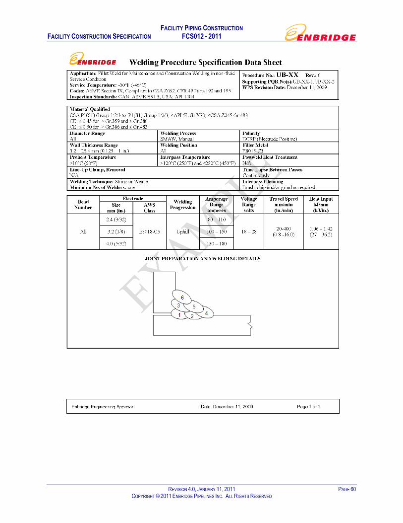
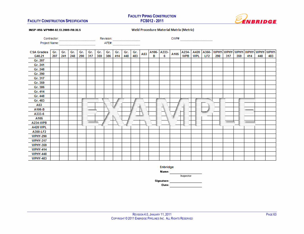
Welding procedures shall be submitted by the Contractor to the Company for review and approval by Pipeline Integrity or Pipeline Integrity's designate. Alternative procedures must be submitted as soon as possible to allow a reasonable approval period for the Company without affecting the work schedule. As a guide, allow two weeks for Company review and approval of welding procedures. Contractors must submit WPS in conjunction with a welding matrix that identifies the specific material, WPS and other relevant variable combinations that are required for construction. Refer to Appendix G - Examples of WPS Datasheets and Weld Procedure Material Matrices. As a minimum, all WPS Datasheet(s) submitted for company approval shall contain the information provided in the appended examples. Prior to performing a weld, the corresponding company approved WPS Datasheet shall be signed off by each welder using the Datasheet and submitted as part of the required permanent records retention turnover documentation.
5.3 Qualification of Welders
Each welder shall be required to provide proof of a provincial welding certification (i.e., Alberta "B" Pressure or a CWB certification) and pass a welder qualification test by visual inspection and either destructive or radiography, or with prior company approval, ultrasonic methods and using an approved qualified welding procedure. The acceptance criteria shall be in accordance with CSA Z662 or ASME Section IX whichever is applicable. The Contractor is responsible for the coordination of 100% NDE of all welds using a NDE service provider contracted directly to Enbridge.
The welder CSA Z662 qualification test may be performed as a production weld if approved by the Company.
A copy of all welders’ qualifications is required as per requirements of CSA Z662 or ASME.
Qualification records shall be made of the tests given to welders and of the detailed results of each test and submitted as part of turnover documentation.
A list of qualified welders and the procedure specifications in accordance with which they are qualified to weld shall be maintained.
Welding parameters for each WPS shall be checked and recorded by the Contractor for each welder as a minimum during welder qualification testing. These records will be kept on file with the Welder Qualification Records.

FACILITY PIPING CONSTRUCTION FACILITY CONSTRUCTION SPECIFICATION FCS012 - 2011
REVISION 4.0, JANUARY 11, 2011 PAGE 7 COPYRIGHT © 2011 ENBRIDGE PIPELINES INC. ALL RIGHTS RESERVED
5.4 Standards of Acceptability for Production Welds
The Contractor shall employ such means required to ensure piping integrity. The standards of acceptability are minimum requirements on welding workmanship and shall meet the standards of acceptability as set out in CSA Z662 or ASME B31.3, whichever is applicable. The Company shall be permitted to reject welds which appear to meet these non-destructive inspection standards of acceptability if, in its opinion, the depth, location or orientation of the discontinuity might be detrimental to the structural integrity of the welds.
Records of welding parameters used for production welding and the resolution of any non-conformance shall be maintained to demonstrate compliance with the requirements of this Specification and the welding procedure specifications. Records shall comprise part of the permanent records retention.
The Company reserves the right to measure welding parameters on any production weld. When the parameters measured on a weld do not comply with the specified values, the Company reserves the right to reject such weld and any weld made after the last compliant record unless the party responsible for the work can demonstrate such welds are in compliance.
Non-compliance to the requirements of this Specification and of the welding procedure specification shall be cause for weld rejection.
5.5 Non-Destructive Examination
5.5.1 Non-Destructive Examination Procedures
The NDE service provider shall be directly contracted by the Company. All NDE shall be coordinated by the construction contractor in a planned and efficient manner.
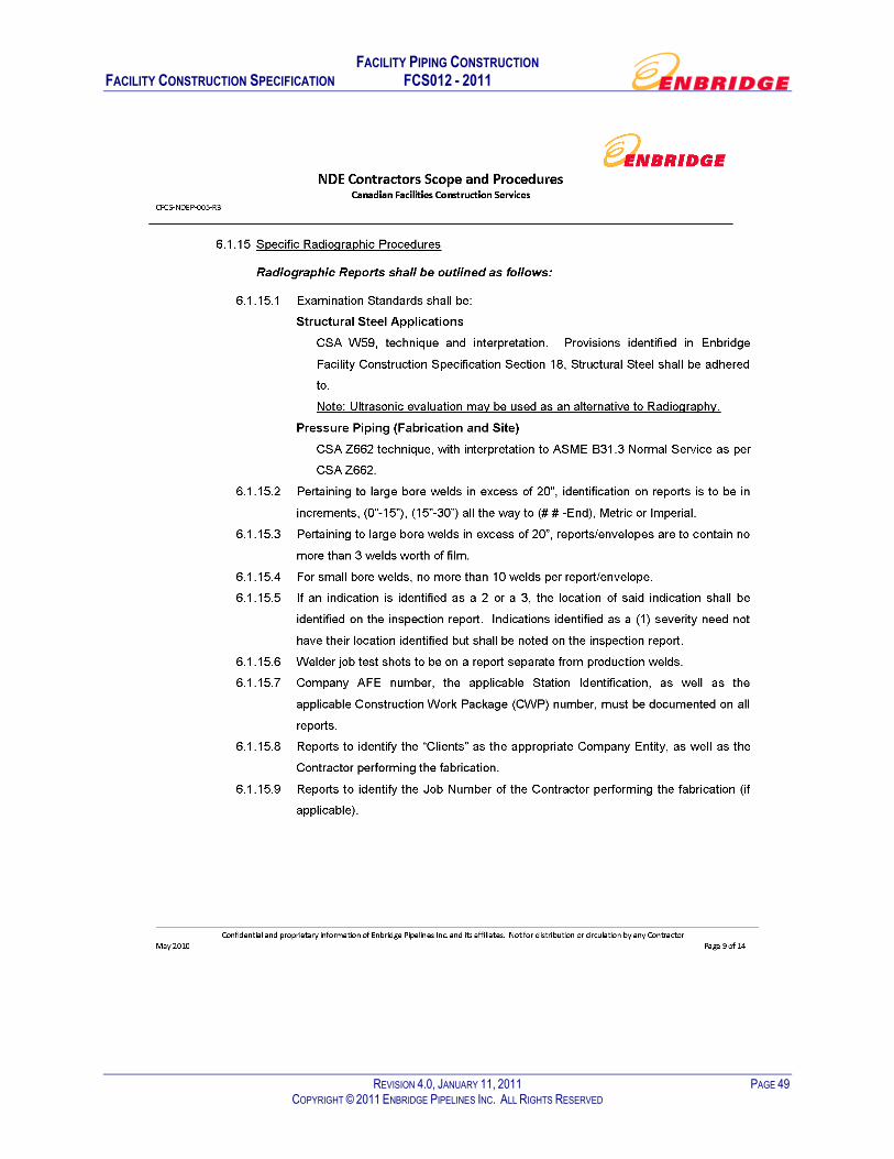
The NDE Contractor shall satisfy the Company that the proposed non-destructive examination methods are capable of identifying imperfections that could result from the particular welding process and joint configuration being considered. The NDE Contractor shall perform their scope of services in accordance with the latest version of the Enbridge Construction Services Radiography Examination Scope and Procedures for NDE Contractors (see Appendix E - Enbridge Construction Services Radiography Examination Scope and Procedures for NDE Contractors).
The NDE Contractor shall be responsible for providing all completed NDE documentation to the construction contractor for their use in performing quality control. This activity shall be completed on a progressive basis.
The construction contractor shall perform their quality control and then submit the completed NDE documentation within 48 hours of receipt to the Company/Inspector as part of the Permanent Records Retention. This activity shall be completed on a progressive basis.
The construction contractor's quality control shall visually inspect and document 100% of all welds as per CSA Z662 and ASME Section V. All NEB regulated station/terminal/facilities butt welds and tie-in welds, including repairs, shall be 100% radiographically examined. All ERCB regulated station/terminal/facilities butt welds and tie-in welds, including repairs, shall be 100% radiographically examined, unless otherwise approved by the Company. Other methods such as liquid penetrant and magnetic particle can be used in situations where radiography may not be appropriate. The acceptance of these or other methods require Company approval through change management.

FACILITY PIPING CONSTRUCTION FACILITY CONSTRUCTION SPECIFICATION FCS012 - 2011
REVISION 4.0, JANUARY 11, 2011 PAGE 8 COPYRIGHT © 2011 ENBRIDGE PIPELINES INC. ALL RIGHTS RESERVED
The Contractor shall provide a suitable high-intensity viewer with sufficient capacity to illuminate radiographs of excessive density without difficulty to verify film flash information, repair locations and to ensure traceability requirements.
All attachment welds to the station piping shall be 100% inspected by magnetic particle methods.
All socket welds shall be subject to 100% inspection using magnetic particle.
Welds on fire water systems shall be subject to a minimum of 15% radiographic inspection.
The Company may choose to ask for a demonstration of an alternate non-destructive method that can accurately detect weld imperfections. Once satisfied, the Company shall approve the use of alternate examination techniques for the work being considered.
5.5.2 Qualifications of NDE Personnel
Personnel engaged in non-destructive examination shall be qualified as specified by CAN/CGSB 48.9712. Persons with a minimum of Level II or III shall interpret radiographs. Other NDE methods shall be performed only by personnel who are qualified to interpret the results. The Company may ask that non-destructive inspection personnel demonstrate their ability to correctly interpret indications.
6 Construction practices
6.1 General
A welding datasheet shall be issued by the fabrication contractor to each welder defining the process variables and constraints prior to commencement of welding for each WPS used.
For position welds, the minimum number of welders shall be as follows:
a) one for less than or equal to NPS 12; and
b) two for greater than NPS 12.
Tack welds are not permitted when using external line-up clamps unless preheating requirements are met.
The welding of alignment lugs (dogs) shall only be permitted in the joint bevel. Lug welds shall be ground out before removal.
Unless otherwise specified, all butt welds shall be full penetration welds.
All pressure retaining joints, including socket welds, shall have a minimum of two passes.
Socket welds shall have 1.6 mm (1/16 in.) minimum gap between the bottom of the socket and end of pipe prior to welding. Minimum gap spacing will be verified by conducting RT inspection per welder on a random basis.
The start of all weld passes shall overlap and no pass shall start closer than 50 mm from the start of the preceding pass.
Pipe shall be cut squarely followed by reaming, burring and cleaning before installation. Pipe runs shall be straight and true.

FACILITY PIPING CONSTRUCTION FACILITY CONSTRUCTION SPECIFICATION FCS012 - 2011
REVISION 4.0, JANUARY 11, 2011 PAGE 9 COPYRIGHT © 2011 ENBRIDGE PIPELINES INC. ALL RIGHTS RESERVED
Where a pipe is cut, pipe identification such as pipe number, specification, grade, heat number, manufacturer and date of manufacture shall be transferred to both ends of the pipe. Dye stamping of the pipe or weld shall not permitted for that purpose.
The welding of supports, bracing bars or counter balance weights to pressure piping and components shall not be permitted.
Bolt holes of all flanges shall straddle the north-south (N-S) or vertical centre lines unless otherwise noted on the drawings.
Electric welded pipe shall be aligned so that the longitudinal seam will be located on the upper surface of the line within 300 mm of the vertical (preferably at the 2 o’clock and 10 o’clock positions). Successive joints of pipe shall be rotated to left or right by not less than 200 mm to prevent the aligning of weld seams in adjacent pipe sections. Longitudinal seams on pipe bends shall be located on the neutral axis of the bend.
The inside diameters of piping components shall be aligned accurately within existing tolerances on diameters, wall thickness and out-of-roundness.
Dimensions of flanged branch connections from centre line of pipe to face of flange shall be equal to the dimensions of a standard welding tee plus the length of a weld neck flange unless otherwise noted on the drawings.
For stub-ins, the hole cut for the branch shall have the bore the full size of the branch inner diameter.
Nipples for connections on insulated piping shall have enough length so as to extend beyond insulation by a minimum of 38 mm.
6.1.1 Internal Cleaning of Station Piping and Spools
Each joint of pipe or spool shall be internally inspected and, if required, cleaned to ensure all foreign material is removed from the entire joint length. The internal cleaning process will be verified by the Company Inspectors.
Preparatory to aligning pipe for welding, the bevelled ends of each joint shall be thoroughly cleaned of paint, rust, mill scale, dirt or any other foreign material detrimental to the quality of the welds. Any satisfactory method approved by the Inspector may be used for this cleaning operation.
6.1.2 Cleaning of Welds
Each bead shall be thoroughly cleaned of scale, dirt and slag by a method satisfactory to the Inspector prior to the application of succeeding beads. The completed weld shall be cleaned free of slag.
6.1.3 Weld Reinforcement Dressing
When files are used for cleaning up the final or “cap” pass, the metal adjacent to the weld shall not be grooved below the pipe surface. Should this occur, the Contractor shall cut out the defective weld or make a repair satisfactory to the Company.
FACILITY PIPING CONSTRUCTION FACILITY CONSTRUCTION SPECIFICATION FCS012 - 2011
REVISION 4.0, JANUARY 11, 2011 PAGE 10 COPYRIGHT © 2011 ENBRIDGE PIPELINES INC. ALL RIGHTS RESERVED
6.2 Repair or Removal of Field Joint Defects
6.2.1 Repair Welding Procedures
The Contractor shall submit welding repair procedures for the Company's approval. The acceptance of repair procedures is contingent upon a demonstration of such procedures for each type of repair to be undertaken. The Contractor shall conform to the approved repair welding procedures for each instance of repair.
At the option of the Company and under the supervision of the Inspector, with the exception of cracks, welds may be repaired by grinding or gouging to sound metal and re-welding. Such repaired areas shall be re-inspected per CSA Z662 or ASME B31.3 requirements, whichever is applicable. No further repairs shall be allowed in previously repaired areas without Company permission.
6.2.2 Repair of Welds
The accumulated length of weld repairs shall not exceed 25% of the total length of the girth weld.
When welding piping together at places where cut-outs have been made for any reason, one replacement weld will be used if it is practical to pull the piping back into position without imposing strain on the piping. Otherwise, a “pup joint” of not less than 1.22 m shall be installed.
6.2.3 Arc Burns
Arc shall be struck only in the weld groove. Arc burns on the pipe surface shall be repaired in accordance with CSA Z662 and the Company must be notified prior to repair.
7 Shop Fabrication Piping
7.1 General
At the discretion of the Company, piping assemblies may be fabricated at the Contractor’s shop or other fabrication facility. The requirements for shop fabricated piping shall be the same as for site fabricated piping except for the following:
a) When the Contractor fabricates piping, they shall determine the location of site welds. It is the Contractor's responsibility to check existing facilities and its own work to verify location, elevations, etc. in order to ensure that adequate field fit allowances are provided. For all piping, it is the Contractor's responsibility to field check and verify all elevations and dimensions to ensure correct fit-up of the piping.
7.2 Right of Entry
Inspectors employed by the Company shall have right of entry to the Contractor's/Subcontractor's shop used for the fabrication of any piping. The Contractor shall afford the Inspector, without charge, any reasonable facilities and information required to satisfy the Inspector that the work is being completed in accordance with the drawings and Specifications.

FACILITY PIPING CONSTRUCTION FACILITY CONSTRUCTION SPECIFICATION FCS012 - 2011
REVISION 4.0, JANUARY 11, 2011 PAGE 11 COPYRIGHT © 2011 ENBRIDGE PIPELINES INC. ALL RIGHTS RESERVED
7.3 Time of Inspection
All piping shall be subject to inspection by the Inspector at any time during fabrication. Ample notice of when fabrication will start and when tests will be made shall be given to the Company so that the Inspector may witness any particular phase of the work as per Enbridge requirements (e.g., hydrotesting).
7.4 Subcontracting
Should the Contractor subcontract any portion of the work, the Subcontractor shall be subject to inspection and testing by the Inspector as would be the case if the Contractor were to perform the fabrication in his own shop. The Contractor is responsible for managing all aspects of their Subcontractors as it relates to all Enbridge requirements. Subcontractors must be pre-approved by the Company.
7.5 Location of Tests
All inspection and tests shall be made at the Contractor’s fabrication shop unless agreed to by the Company.
All flanged connections to be made with new specified gaskets and torquing of the bolts following Appendix B - Flange Installation Quality Control Form. Connections shall be documented by the contractor and verified by the Inspector prior to coating/painting as agreed upon by the project team.
7.6 Receiving, Shipping and Handling
The Contractor is responsible for receiving and inventory of all Company supplied material. The Contractor is responsible for preparing, loading and transporting all fabricated piping to site.
Before transporting, all piping spools shall be cleaned on the inside and outside. Suitable end closures shall be provided and installed to protect piping against the ingress of dirt and moisture during transportation and site storage. The Contractor shall ensure that all piping spools are protected from damage during transportation.
Adequate precautions shall be taken to prevent damage to spools after fabrication.
The Contractor shall ensure that the spool sizes and configurations are such that they can be safely transported to site and allow for safe off-loading at site.
Transportation to site shall not be made until the Company has accepted the work.
The Contractor shall notify the Company as soon as possible of any unused pieces of piping.
8 Site Fabrication and Installation
8.1 Storage and Handling
The Contractor shall handle the piping in such a manner to prevent any damage to the piping and any applied coating/painting. The Contractor shall take adequate precautions to avoid damaging of pipe ends or the denting, gouging, grooving or flattening of the pipe. Piping shall be moved by means of an engineered and approved lifting device complete with certification records. In addition, only an approved spreader bar shall be used. The Contractor shall submit

FACILITY PIPING CONSTRUCTION FACILITY CONSTRUCTION SPECIFICATION FCS012 - 2011
REVISION 4.0, JANUARY 11, 2011 PAGE 12 COPYRIGHT © 2011 ENBRIDGE PIPELINES INC. ALL RIGHTS RESERVED
for approval the proposed lifting hook and spreader bar design. A registered Professional Engineer shall approve the engineering integrity of the design prior to submission.
All piping and fittings shall be kept free of dirt and other foreign matter while storing, handling, fabricating or erecting. While in storage, piping and fittings shall be kept off the ground in a safe, neat and orderly fashion on sleepers, racks, etc. Flange faces, open ends and pipe threads shall be protected prior to, during and after installation.
Just prior to installation, the Contractor shall request a visual inspection by the Inspector of the piping and fittings to ensure that it is clean, dry and free of foreign matter.
The Contractor shall remove all dents in the pipe by cutting out the dented length of the pipe, re-bevelling the cut ends, welding up and recoating upon approval by the inspector/project team. If the Contractor has dented the pipe, this work shall be at the Contractor’s expense.
8.2 Pipe Fabrication
When the Contractor fabricates piping, they shall determine the location of field welds on drawings. It is the Contractor's responsibility to check existing facilities and its own work to verify location, elevations, etc. in order to ensure that adequate field fit allowances are provided. For all piping, it is the Contractor's responsibility to field check all elevations and dimensions to ensure correct fit up of the piping and equipment.
Where the Contractor will be completing piping left by others, the cutting off of weld caps and removing blind flanges, etc. (except double faced blinds) shall be the responsibility of the Contractor at no cost to the Company.
8.3 Pipe Installation
Open ends of installed pipe shall be sealed at the end of each day.
Where screwed fittings and valves are specified to be back-welded, a continuous seal weld shall be made. Thread compound shall not be used on threaded components that will be seal welded. Threads must be fully covered by weld bead.
For flanged connections, new specified gaskets shall be used for every assembly. The Contractor shall furnish sufficient gaskets to meet this requirement. Gaskets are to be free of foreign materials. Inside diameter of gaskets shall not protrude inside the piping ID. Torque the bolts following Appendix A - Tightening and Torquing Flanges and document the connection using Appendix B - Flange Installation Quality Control Form.
Where “flat ring” gaskets are specified, these shall be of the type whose outside diameter is contained within the bolt circle. Where “full face” gaskets are specified, these shall be of the type whose outside diameter is the same as the outside diameter of the flange.
9 Underground Piping
The Contractor shall install all piping to the grades, lines and elevations shown on the drawings.
Tolerances shall be as follows:
a) underground piping shall be within 75 mm of specified line and within 50 mm of specified grade, with no sags or low spots; and
b) stub up risers shall be within 25 mm in any direction of the location shown on the drawings.

FACILITY PIPING CONSTRUCTION FACILITY CONSTRUCTION SPECIFICATION FCS012 - 2011
REVISION 4.0, JANUARY 11, 2011 PAGE 13 COPYRIGHT © 2011 ENBRIDGE PIPELINES INC. ALL RIGHTS RESERVED
Buried flanges shall not be used for joining pipe sections unless specifically indicated in the drawings.
When stringing alongside a pipe trench, pipe shall be securely supported on timber or sand-filled sacks supported by skids in such a way as to prevent damage to the exterior surface and/or painting/coating of the piping.
Piping for underground service shall be checked before being lowered into the trench to ensure that no foreign material, manufacturer's defects or cracks exist that might prevent the proper jointing of the pipe or its operation. Piping shall be carefully lowered into the trench by means of approved tools or equipment (i.e., cranes, side booms, etc.) in a manner that will prevent damage to the piping.
When installing small diameter fittings to tap into piping, before backfilling cover the fitting with a short length (i.e., up to 2 ft.) of plastic pipe or a pylon as a warning for future excavating activities.
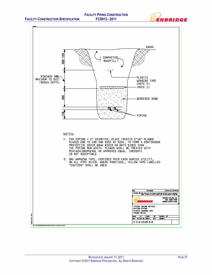
When backfilling buried small piping (less than 50.8 mm (2 in.) diameter), install mechanical protection and plastic warning tape/ribbon in accordance with Appendix D - Plastic Warning Tape Detail Drawing.
Plastic warning tape/ribbon shall be placed over all station piping during backfill. As a guideline, plastic warning tape/ribbon shall be buried approximately 450 mm (18 in.) above the top of the largest utility in accordance with Appendix D - Plastic Warning Tape Detail Drawing. Where practical, yellow tape continuously labelled “Caution” shall be used for station piping.
Plastic Marking Tape shall be of a type specifically manufactured for marking underground facilities. The tape shall be acid and alkali-resistant polyethylene film, 150 mm (6 in.) wide with minimum thickness of 0.10 mm (0.004 in.). Tape shall have a minimum strength of 121.4 Mpa (1750 PSI) lengthwise and 10.3 Mpa (1500 PSI) crosswise.
Precaution shall be taken to ensure that displacement of underground pipe does not occur through soil displacement or flotation due to the presence of trench water. Pipe that has been displaced shall be removed from the trench and re-laid after the trench is dewatered and reshaped as necessary.
All underground piping shall be inspected and approved by the Inspector prior to backfilling.
10 Field Run Piping
When pipe routing is selected and the piping is installed by the Contractor, the Contractor shall, prior to commencing any work, review the proposed routing and installation details with the Inspector and obtain the Inspector's approval from the project team before proceeding with the work.
Multiple runs of site routed piping shall be grouped in established banks at organised elevations with a change in elevation provided at each change of direction and with sufficient space allowed between piping runs so that proper maintenance can be performed. Particular considerations shall be given to insulated piping so that there is no interference between insulation, piping supports and structural steel.
All piping shall be installed in a neat and orderly manner along straight lines, both vertically and horizontally, parallel to building walls and partitions and building lines. Piping supports shall be supplied and installed by the Contractor. All piping shall be adequately supported and braced against cross sway where necessary.

FACILITY PIPING CONSTRUCTION FACILITY CONSTRUCTION SPECIFICATION FCS012 - 2011
REVISION 4.0, JANUARY 11, 2011 PAGE 14 COPYRIGHT © 2011 ENBRIDGE PIPELINES INC. ALL RIGHTS RESERVED
Overhead clearance shall be 2.3 m (minimum) in buildings and above walkways and platforms.
Cold springing of piping shall only be performed when requested on the drawings. No cold springing shall be done except when the Company has given specific approval prior to the work. In general, cold springing will not be approved on any piping larger than 60.3 mm diameter.
Piping shall not be run near the floor, across walkways or working spaces where it will create a hazard. Areas for access shall be free of piping interference.
Under no circumstances shall buried threaded connections be used.
No piping less than NPS 2 shall be buried. When routing smaller piping from above grade to a buried connection, a reducer shall be located a minimum of 0.3 m (1 ft.) above finished grade. Provision should be made for the isolation and removal of the above grade piping without draining buried process lines (i.e. valve and union or flanges).
The piping shall be installed with flanges or unions so that the removal of equipment can take place without the cutting of any piping.
Lube oil, gland seal and cooling piping at equipment such as pumps shall be supported independent of the equipment and arranged to permit easy dismantling of the equipment without removal of block valves.
No bushings or sharp edge swages shall be used.
Modified fittings such as tapped blind flanges shall not be used.
In areas without leak detection and spill containment threaded piping is to be avoided in favour of welded or Swagelok SS tube and tube compression fittings.
11 Tubing Installation
All tubing connections shall be made using only Swagelok tube fittings and shall be made by an individual who has completed the Swagelok Tube Fitting Installation and Safety Seminar. The installer shall follow Swagelok's installation instructions for tube fittings and possess a Swagelok Certified Safety Installation Card. A copy of this card shall be retained for the Permanent Construction Records. All tubing connections shall be inspected and documented on the form provided in Appendix C - Tubing Connection Verification Form.
12 Spring Support Installation
Spring support installation details are shown on individual detail drawings. Installation, settings, etc., are to be in accordance with these drawings.
Unless specified otherwise on pipe support details, spring supports should be installed with travel stops in place. Travel stops on spring hangers shall not be removed before hydrotest. After completion of hydrotest at site, the stops in the spring supports shall be removed by the Contractor. For piping that is fabricated and hydrotested at the fabrication shop, the spring support travel stops shall not be removed after the shop hydrotest but after installation at site by the Contractor.
After the removal of travel stops, the hanger should be adjusted until the load indicator moves to the cold position. On inspection of the system, after a reasonable period of operation, the load indicator should be at the hot position. If it is not, the support should be readjusted to the hot position.

FACILITY PIPING CONSTRUCTION FACILITY CONSTRUCTION SPECIFICATION FCS012 - 2011
REVISION 4.0, JANUARY 11, 2011 PAGE 15 COPYRIGHT © 2011 ENBRIDGE PIPELINES INC. ALL RIGHTS RESERVED
During installation of spring hangers or supports on pump piping systems, it is essential that pumps be aligned within the limits of misalignment allowed by the pump manufacturer, applicable Company specifications and industry standards. At this stage, the piping system will be empty of process fluid and at ambient temperature. Pipe flanges should be carefully mated to the pump to minimize initial pipe strains on the pump.
Compressor or turbine piping which will contain vapour shall be aligned cold when the system is complete with stops removed.
Installer shall not modify, add, delete or move supports on a spring supported system without the approval of the design engineer.
13 Procedure for Pump Piping Installation
This procedure should be followed to ensure pump case stress is minimised by proper pump suction and discharge piping installation and alignment.
If the contractor has an alternative installation procedure, it shall be submitted to the Company Project Engineer for approval. This shall be done well in advance to permit discussion and approval prior to its use.
Axial direction means in the same direction as the pump shaft. Radial direction is perpendicular to the pump shaft direction.
13.1 Preparation
1) The pump and motor should be aligned to within 0.001 in./ft. in the horizontal and vertical angular offset and within 0.001 in. soft foot (see FCS015 - Mechanical Equipment Installation). The pump flanges should be aligned with the horizontal scribe marks on the pump base.
2) Mount dial indicators on the horizontal, vertical and axial positions taking readings off the pump hub with the spacer removed. This will indicate whether there is any movement in the pump when the pump elbows are tightened.
13.1.1 Method 1 (Tie-In Welds Away from Pump)
1) Fabricate pump elbow (stub end, elbow and flange ring). Ensure that the planes of the stub end faces are perpendicular to each other and to the plane of the elbow.
2) Fabricate the remaining piping up to the tie-in point leaving tack welds on one joint in each plane (axial, vertical, and radial directions). Do not weld the tie-in. Allow for downward movement of the pipe due to the compression of the neoprene pad on the pipe supports.
3) Attach the pump elbow and piping to the pump with new gaskets and torque the bolts following Appendix A - Tightening and Torquing Flanges. Ensure that the flanges are faced using a hand wrench according to this procedure.
4) Tighten the piping support at the bottom of the pump elbow.
5) The bevel ends of the tie-in weld must be within 0.020 in. of each other in the horizontal and vertical positions and have the proper gap for welding without applying any force to either end of the pipe. If these dimensions are not met, then one or more of the tack welded joints and/or the tie-in bevel ends must be cut and adjustments made to achieve this line up.
FACILITY PIPING CONSTRUCTION FACILITY CONSTRUCTION SPECIFICATION FCS012 - 2011
REVISION 4.0, JANUARY 11, 2011 PAGE 16 COPYRIGHT © 2011 ENBRIDGE PIPELINES INC. ALL RIGHTS RESERVED
6) After the tie-in weld is made, the remaining tack welded joints may be completed. Two welders should work 180° apart to minimise distortion due to the heat of welding. The Inspector shall witness the final tie-in weld.
7) Allow the pipe to cool.
8) The dial indicators should read zero movement (0.002 in. maximum) in the pump hub.
9) Loosen both pump elbow flanges to relieve any induced strain from the welding and retighten as in step 3 above. There should be zero movement in the pump hub when the pump elbow is tightened.
13.1.2 Method 2 (Tie-In Welds on Pump Elbow)
1) Fabricate and install the pump piping up to the pump elbow and tighten the pipe support.
2) The horizontal flange below the pump elbow must be level to within 0.002 in./ft. in the axial and radial directions.
3) Shim the stub end flange faces the thickness of a compressed flexitallic spiral wound gasket away from the opposing raised face weld neck flange to determine the proper length of the stub ends before welding them to the elbow. Insert 4 bolts at the 3, 6, 9 and 12 o’clock positions and soft tighten to hold the shims in place.
4) Cut the stub ends and weld the elbow. Two welders working 180° apart to minimise distortion due to the heat of welding shall weld the pipe.
5) Shim the bottom elbow flange to the weld neck flange as in step 3 and note the upper flange face in relation to the pump flange. The faces should be parallel to within 0.020 in./ft. in the vertical and axial directions. The raised faces should be concentric with each other to within 0.060 in. If not, the elbow may require mitre cutting and re-welding to obtain these tolerances.
6) Assuming proper face tolerances have been achieved, install the bolts and gaskets. Hand tighten the bolts on the lower flange. This will help ensure the faces are square for the final tie-up.
7) Hand tighten the bolts on the upper flange. The dial gages should indicate no more than 0.001 in. movement in any direction after this and any subsequent tightening.
8) Tighten the bolts as per Appendix A - Tightening and Torquing Flanges.
Caution: Monitor the dial indicator continuously to ensure movement in any one direction does not exceed 0.001 in.
Do not use the dial indicators to determine flange bolt tightening sequence. This may result in uneven flange gasket face loading.
14 Torquing Procedure
Refer to Appendix A - Tightening and Torquing Flanges.
15 Insulation
Piping shall be insulated where indicated on the drawings. The Contractor shall provide a complete and finished insulation system.
FACILITY PIPING CONSTRUCTION FACILITY CONSTRUCTION SPECIFICATION FCS012 - 2011
REVISION 4.0, JANUARY 11, 2011 PAGE 17 COPYRIGHT © 2011 ENBRIDGE PIPELINES INC. ALL RIGHTS RESERVED
Insulation shall not be installed until all radiographic inspection and testing is complete and all hydrostatic testing and tracing installation is complete. Temporary support and handling of insulated pipe shall comply with the insulation manufacturer's recommendations.
Insulated pipe shall only be primed as per FCS019 - Painting and P-210 - Shop and Field Painting: Construction – Appendix 1.
When a line is to be insulated, the insulation shall extend to point of connection to an un-insulated line or to equipment.
15.1 Above Ground Insulation System
Insulation shall be as per identified in the IFC drawings.
For fibreglass insulation, the following shall apply:
a) insulation for fittings, flanges and valves shall be mitred sections of pipe insulation or pre-formed shapes;
b) insulation shall be installed such that longitudinal joints are staggered on adjacent sections and with all circumferenced joints tightly butted;
c) insulation shall be securely wired in place with 18 gauge stainless steel wire on 12 in. centres;
d) joints and voids shall be filled with insulation cement;
e) external finish shall be corrugated aluminum jacketing, 0.016 in. thick, complete with integral vapour barrier, Childers or equal. Pre-formed aluminum elbow, tee, valve, flange, etc. jacket sections shall be used;
f) jacketing shall be secured using 0.5 in. wide by 0.020 in. thick type 304 stainless steel bands on 12 in. centres, using stainless steel wing seals;
g) joint sealant shall be Childers CP-70 or equal;
h) jacket joints shall be lapped a minimum of 2 in. On horizontal piping, jacket seams shall be placed at the side of the piping below the centreline, with a lap downwards to shed water;
i) on piping entering the ground the last 300 mm above ground shall be insulated with Foamglass and wrapped with Pittwrap (Pittsburgh Corning);
j) the aluminum jacketing from the fibreglass section immediately above shall be extended to overlap the Pittwrap (Pittsburgh Corning) by 100 mm; and
k) all jacket joints and seams shall be sealed with caulking. All protrusions through the jacketing shall be flashed and sealed as required to be watertight.
15.2 Below Ground Insulation Systems
a) Insulation shall be single layer Foamglass manufactured by Pittsburgh Corning or other Company approved material.
b) Insulation for fittings shall be mitred sections of pipe insulation.
c) External finish shall be Pittwrap and Pittwrap SS jacketing, applied in accordance with the manufacturer's instructions.

FACILITY PIPING CONSTRUCTION FACILITY CONSTRUCTION SPECIFICATION FCS012 - 2011
REVISION 4.0, JANUARY 11, 2011 PAGE 18 COPYRIGHT © 2011 ENBRIDGE PIPELINES INC. ALL RIGHTS RESERVED
15.3 Flexible Reusable Pipe Insulation
a) Flexible covers shall be designed to enclose the entire seal drain piping from the pump up to, and including, the orificed gate valve.
b) Covers shall have all parting lines covered with a flap constructed of the same material as the outer jacket. The flap shall be installed in a manner which provides proper water shedding. The flap shall be secured with Velcro.
c) All covers shall have sufficient through blanket quilting pins installed in sufficient quantities to prevent the insulation insert from shifting or pulling away from the edges of the cover shell.
d) Wind flaps complete with drawcords shall be incorporated into the blanket design to securely close the blanket ends over the line insulation.
e) All drawcord ends shall be heat sealed to prevent cord fraying. Cord ends shall be knotted to prevent the cord from pulling out of the wind flap.
f) Sewn covers shall use inside seam construction and shall have all slits and penetration openings top stitched to provide added strength at stress points.
g) All blankets shall have a printed tag sewn to the outer jacket. The tag shall identify:
i. Manufacturer’s name and address;
ii. Date of manufacture; and
iii. Manufacturer’s part or serial number.
k) Covers shall be sewn based on dimensions taken from the completed pump seal drain piping according to the insulation manufacturer’s instructions.
l) Materials:
i. Outer Jacket and Inner Liner 14 oz./sq. yard Teflon coated fibreglass cloth
ii. Insulation 1 in. thick type E needled fibreglass cloth
iii. Stitching Teflon coated fibreglass thread

FACILITY PIPING CONSTRUCTION FACILITY CONSTRUCTION SPECIFICATION FCS012 - 2011
REVISION 4.0, JANUARY 11, 2011 PAGE 19 COPYRIGHT © 2011 ENBRIDGE PIPELINES INC. ALL RIGHTS RESERVED
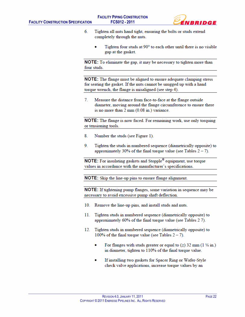
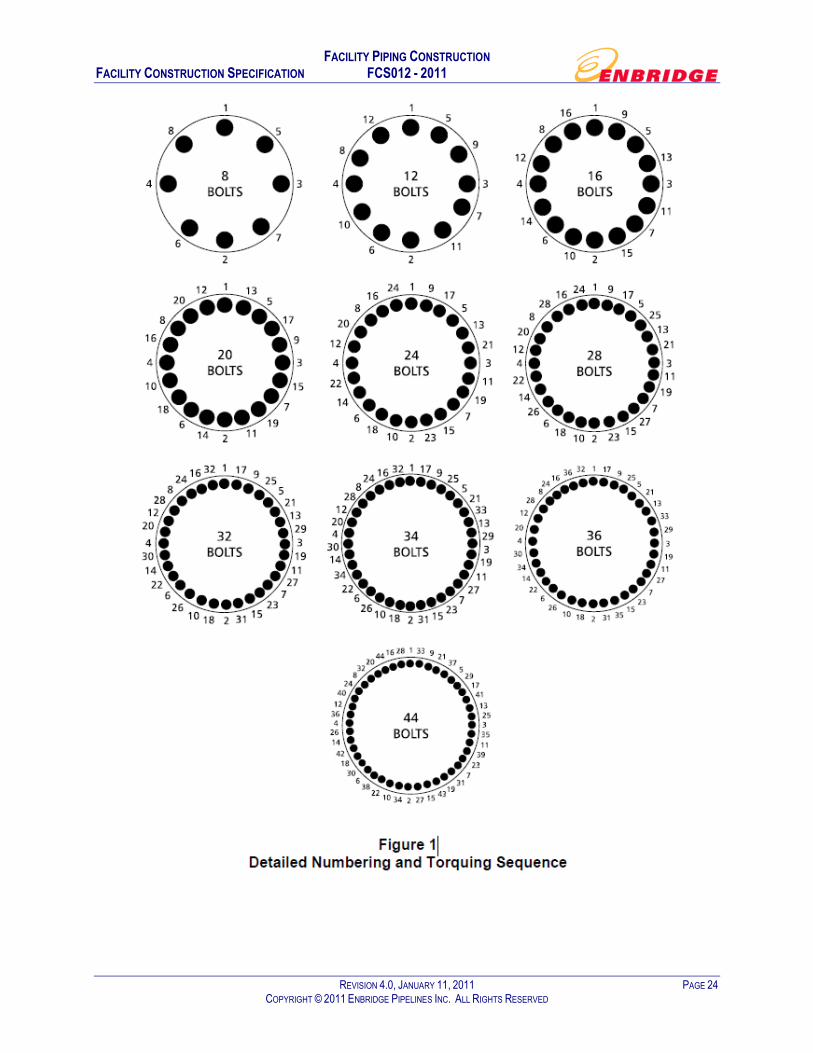
Appendix A Tightening and Torquing Flanges
FACILITY PIPING CONSTRUCTION FACILITY CONSTRUCTION SPECIFICATION FCS012 - 2011
REVISION 4.0, JANUARY 11, 2011 PAGE 20 COPYRIGHT © 2011 ENBRIDGE PIPELINES INC. ALL RIGHTS RESERVED
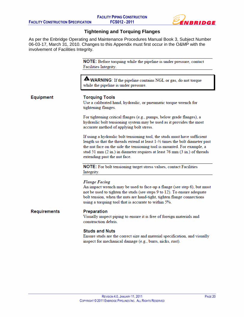
Tightening and Torquing Flanges
As per the Enbridge Operating and Maintenance Procedures Manual Book 3, Subject Number 06-03-17, March 31, 2010. Changes to this Appendix must first occur in the O&MP with the involvement of Facilities Integrity.

FACILITY PIPING CONSTRUCTION FACILITY CONSTRUCTION SPECIFICATION FCS012 - 2011
REVISION 4.0, JANUARY 11, 2011 PAGE 21 COPYRIGHT © 2011 ENBRIDGE PIPELINES INC. ALL RIGHTS RESERVED
FACILITY PIPING CONSTRUCTION FACILITY CONSTRUCTION SPECIFICATION FCS012 - 2011
REVISION 4.0, JANUARY 11, 2011 PAGE 22 COPYRIGHT © 2011 ENBRIDGE PIPELINES INC. ALL RIGHTS RESERVED

FACILITY PIPING CONSTRUCTION FACILITY CONSTRUCTION SPECIFICATION FCS012 - 2011
REVISION 4.0, JANUARY 11, 2011 PAGE 23 COPYRIGHT © 2011 ENBRIDGE PIPELINES INC. ALL RIGHTS RESERVED
FACILITY PIPING CONSTRUCTION FACILITY CONSTRUCTION SPECIFICATION FCS012 - 2011
REVISION 4.0, JANUARY 11, 2011 PAGE 24 COPYRIGHT © 2011 ENBRIDGE PIPELINES INC. ALL RIGHTS RESERVED

FACILITY PIPING CONSTRUCTION FACILITY CONSTRUCTION SPECIFICATION FCS012 - 2011
REVISION 4.0, JANUARY 11, 2011 PAGE 25 COPYRIGHT © 2011 ENBRIDGE PIPELINES INC. ALL RIGHTS RESERVED

FACILITY PIPING CONSTRUCTION FACILITY CONSTRUCTION SPECIFICATION FCS012 - 2011
REVISION 4.0, JANUARY 11, 2011 PAGE 26 COPYRIGHT © 2011 ENBRIDGE PIPELINES INC. ALL RIGHTS RESERVED

FACILITY PIPING CONSTRUCTION FACILITY CONSTRUCTION SPECIFICATION FCS012 - 2011
REVISION 4.0, JANUARY 11, 2011 PAGE 27 COPYRIGHT © 2011 ENBRIDGE PIPELINES INC. ALL RIGHTS RESERVED

FACILITY PIPING CONSTRUCTION FACILITY CONSTRUCTION SPECIFICATION FCS012 - 2011
REVISION 4.0, JANUARY 11, 2011 PAGE 28 COPYRIGHT © 2011 ENBRIDGE PIPELINES INC. ALL RIGHTS RESERVED

FACILITY PIPING CONSTRUCTION FACILITY CONSTRUCTION SPECIFICATION FCS012 - 2011
REVISION 4.0, JANUARY 11, 2011 PAGE 29 COPYRIGHT © 2011 ENBRIDGE PIPELINES INC. ALL RIGHTS RESERVED

FACILITY PIPING CONSTRUCTION FACILITY CONSTRUCTION SPECIFICATION FCS012 - 2011
REVISION 4.0, JANUARY 11, 2011 PAGE 30 COPYRIGHT © 2011 ENBRIDGE PIPELINES INC. ALL RIGHTS RESERVED

FACILITY PIPING CONSTRUCTION FACILITY CONSTRUCTION SPECIFICATION FCS012 - 2011
REVISION 4.0, JANUARY 11, 2011 PAGE 31 COPYRIGHT © 2011 ENBRIDGE PIPELINES INC. ALL RIGHTS RESERVED
Note: Before torquing while the pipeline is under pressure, contact Facilities Integrity.
WARNING: If the pipeline contains NGL or gas, do not torque while the pipeline is under pressure.

FACILITY PIPING CONSTRUCTION FACILITY CONSTRUCTION SPECIFICATION FCS012 - 2011
REVISION 4.0, JANUARY 11, 2011 PAGE 32 COPYRIGHT © 2011 ENBRIDGE PIPELINES INC. ALL RIGHTS RESERVED
Appendix B Flange Installation Quality Control Form

FACILITY PIPING CONSTRUCTION FACILITY CONSTRUCTION SPECIFICATION FCS012 - 2011
REVISION 4.0, JANUARY 11, 2011 PAGE 33 COPYRIGHT © 2011 ENBRIDGE PIPELINES INC. ALL RIGHTS RESERVED

FACILITY PIPING CONSTRUCTION FACILITY CONSTRUCTION SPECIFICATION FCS012 - 2011
REVISION 4.0, JANUARY 11, 2011 PAGE 34 COPYRIGHT © 2011 ENBRIDGE PIPELINES INC. ALL RIGHTS RESERVED
Appendix C Tubing Connection Verification Form

FACILITY PIPING CONSTRUCTION FACILITY CONSTRUCTION SPECIFICATION FCS012 - 2011
REVISION 4.0, JANUARY 11, 2011 PAGE 35 COPYRIGHT © 2011 ENBRIDGE PIPELINES INC. ALL RIGHTS RESERVED

FACILITY PIPING CONSTRUCTION FACILITY CONSTRUCTION SPECIFICATION FCS012 - 2011
REVISION 4.0, JANUARY 11, 2011 PAGE 36 COPYRIGHT © 2011 ENBRIDGE PIPELINES INC. ALL RIGHTS RESERVED
Appendix D Plastic Warning Tape Detail Drawing
FACILITY PIPING CONSTRUCTION FACILITY CONSTRUCTION SPECIFICATION FCS012 - 2011
REVISION 4.0, JANUARY 11, 2011 PAGE 37 COPYRIGHT © 2011 ENBRIDGE PIPELINES INC. ALL RIGHTS RESERVED

FACILITY PIPING CONSTRUCTION FACILITY CONSTRUCTION SPECIFICATION FCS012 - 2011
REVISION 4.0, JANUARY 11, 2011 PAGE 38 COPYRIGHT © 2011 ENBRIDGE PIPELINES INC. ALL RIGHTS RESERVED
Appendix E Enbridge Construction Services Radiograpohy Examination Scope
and Procedures for NDE Contractors

FACILITY PIPING CONSTRUCTION FACILITY CONSTRUCTION SPECIFICATION FCS012 - 2011
REVISION 4.0, JANUARY 11, 2011 PAGE 39 COPYRIGHT © 2011 ENBRIDGE PIPELINES INC. ALL RIGHTS RESERVED

FACILITY PIPING CONSTRUCTION FACILITY CONSTRUCTION SPECIFICATION FCS012 - 2011
REVISION 4.0, JANUARY 11, 2011 PAGE 40 COPYRIGHT © 2011 ENBRIDGE PIPELINES INC. ALL RIGHTS RESERVED

FACILITY PIPING CONSTRUCTION FACILITY CONSTRUCTION SPECIFICATION FCS012 - 2011
REVISION 4.0, JANUARY 11, 2011 PAGE 41 COPYRIGHT © 2011 ENBRIDGE PIPELINES INC. ALL RIGHTS RESERVED

FACILITY PIPING CONSTRUCTION FACILITY CONSTRUCTION SPECIFICATION FCS012 - 2011
REVISION 4.0, JANUARY 11, 2011 PAGE 42 COPYRIGHT © 2011 ENBRIDGE PIPELINES INC. ALL RIGHTS RESERVED

FACILITY PIPING CONSTRUCTION FACILITY CONSTRUCTION SPECIFICATION FCS012 - 2011
REVISION 4.0, JANUARY 11, 2011 PAGE 43 COPYRIGHT © 2011 ENBRIDGE PIPELINES INC. ALL RIGHTS RESERVED

FACILITY PIPING CONSTRUCTION FACILITY CONSTRUCTION SPECIFICATION FCS012 - 2011
REVISION 4.0, JANUARY 11, 2011 PAGE 44 COPYRIGHT © 2011 ENBRIDGE PIPELINES INC. ALL RIGHTS RESERVED

FACILITY PIPING CONSTRUCTION FACILITY CONSTRUCTION SPECIFICATION FCS012 - 2011
REVISION 4.0, JANUARY 11, 2011 PAGE 45 COPYRIGHT © 2011 ENBRIDGE PIPELINES INC. ALL RIGHTS RESERVED

FACILITY PIPING CONSTRUCTION FACILITY CONSTRUCTION SPECIFICATION FCS012 - 2011
REVISION 4.0, JANUARY 11, 2011 PAGE 46 COPYRIGHT © 2011 ENBRIDGE PIPELINES INC. ALL RIGHTS RESERVED

FACILITY PIPING CONSTRUCTION FACILITY CONSTRUCTION SPECIFICATION FCS012 - 2011
REVISION 4.0, JANUARY 11, 2011 PAGE 47 COPYRIGHT © 2011 ENBRIDGE PIPELINES INC. ALL RIGHTS RESERVED

FACILITY PIPING CONSTRUCTION FACILITY CONSTRUCTION SPECIFICATION FCS012 - 2011
REVISION 4.0, JANUARY 11, 2011 PAGE 48 COPYRIGHT © 2011 ENBRIDGE PIPELINES INC. ALL RIGHTS RESERVED
FACILITY PIPING CONSTRUCTION FACILITY CONSTRUCTION SPECIFICATION FCS012 - 2011
REVISION 4.0, JANUARY 11, 2011 PAGE 49 COPYRIGHT © 2011 ENBRIDGE PIPELINES INC. ALL RIGHTS RESERVED

FACILITY PIPING CONSTRUCTION FACILITY CONSTRUCTION SPECIFICATION FCS012 - 2011
REVISION 4.0, JANUARY 11, 2011 PAGE 50 COPYRIGHT © 2011 ENBRIDGE PIPELINES INC. ALL RIGHTS RESERVED

FACILITY PIPING CONSTRUCTION FACILITY CONSTRUCTION SPECIFICATION FCS012 - 2011
REVISION 4.0, JANUARY 11, 2011 PAGE 51 COPYRIGHT © 2011 ENBRIDGE PIPELINES INC. ALL RIGHTS RESERVED

FACILITY PIPING CONSTRUCTION FACILITY CONSTRUCTION SPECIFICATION FCS012 - 2011
REVISION 4.0, JANUARY 11, 2011 PAGE 52 COPYRIGHT © 2011 ENBRIDGE PIPELINES INC. ALL RIGHTS RESERVED

FACILITY PIPING CONSTRUCTION FACILITY CONSTRUCTION SPECIFICATION FCS012 - 2011
REVISION 4.0, JANUARY 11, 2011 PAGE 53 COPYRIGHT © 2011 ENBRIDGE PIPELINES INC. ALL RIGHTS RESERVED

FACILITY PIPING CONSTRUCTION FACILITY CONSTRUCTION SPECIFICATION FCS012 - 2011
REVISION 4.0, JANUARY 11, 2011 PAGE 54 COPYRIGHT © 2011 ENBRIDGE PIPELINES INC. ALL RIGHTS RESERVED

FACILITY PIPING CONSTRUCTION FACILITY CONSTRUCTION SPECIFICATION FCS012 - 2011
REVISION 4.0, JANUARY 11, 2011 PAGE 55 COPYRIGHT © 2011 ENBRIDGE PIPELINES INC. ALL RIGHTS RESERVED
Appendix F Boiler Pressure Vessel Governing Bodies for Provinces and
Territories

FACILITY PIPING CONSTRUCTION FACILITY CONSTRUCTION SPECIFICATION FCS012 - 2011
REVISION 4.0, JANUARY 11, 2011 PAGE 56 COPYRIGHT © 2011 ENBRIDGE PIPELINES INC. ALL RIGHTS RESERVED
British Columbia Safety Authority Safety Standards Act Power Engineers, Boiler, Pressure Vessel and Refrigeration Safety Regulation http://www.safetyauthority.ca/
Alberta Boilers Safety Association Safety Codes Act http://www.absa.ca/
Saskatchewan Boiler and Pressure Vessel Safety Board B‐5.1 ‐ Boiler and Pressure Vessel Act, 1999
http://www.cpsp.gov.sk.ca/Boiler‐and‐Pressure‐Vessel‐Safety
Manitoba Labour and Immigration Workplace Safety and Health Division The Steam and Pressure Act The Power Engineers Act http://www.gov.mb.ca/labour/safety/me/pressure.html
Ontario TSSA Boiler and Pressure Vessel Act Technical Standards and Safety Act, 2000 http://www.tssa.org/
Quebec Service de l'inspection de la Fabrication D'appareils sous pression An Act Respecting Pressure Vessels http://www.rbq.gouv.qc.ca/dirEnglish/general/Pressure_Vessels_forms.asp
Nova Scotia Department of Labour and Workforce Development Steam Boilers and Pressure Vessel Act Technical Safety Act http://www.gov.ns.ca/lwd/legislation/
New Brunswick Department of Public Safety Boiler and Pressure Vessel Act
http://www.gnb.ca/0276/index‐e.asp
Prince Edward Island Department of Communities, Cultural affairs and Labour – Planning and Inspection Division Boiler and Pressure Vessel Act
http://www.gov.pe.ca/commcul/pais‐info/index.php3
Newfoundland Labrador Department of Government Services Boiler, Pressure Vessel and Compressed Gas Regulations under the Public Safety Act http://www.gs.gov.nl.ca/gs/gsc/bpv/
Yukon Department of Community Services – Building Safety Division Boiler and Pressure Vessel Act http://www.community.gov.yk.ca/buildingsafety/index.html
Northwest Territories Public Works and Services Boiler and Pressure Vessel Act http://www.pws.gov.nt.ca/elec‐mech/boilers/boilers.htm

FACILITY PIPING CONSTRUCTION FACILITY CONSTRUCTION SPECIFICATION FCS012 - 2011
REVISION 4.0, JANUARY 11, 2011 PAGE 57 COPYRIGHT © 2011 ENBRIDGE PIPELINES INC. ALL RIGHTS RESERVED
Nunavut Public and Business Services – Safety Services Division Boiler and Pressure Vessel Act
http://cgs.gov.nu.ca/en/protection‐services/safetyservices/boiler

FACILITY PIPING CONSTRUCTION FACILITY CONSTRUCTION SPECIFICATION FCS012 - 2011
REVISION 4.0, JANUARY 11, 2011 PAGE 58 COPYRIGHT © 2011 ENBRIDGE PIPELINES INC. ALL RIGHTS RESERVED
Appendix G Examples of WPS Datasheets and Weld Procedure Material Matrices

FACILITY PIPING CONSTRUCTION FACILITY CONSTRUCTION SPECIFICATION FCS012 - 2011
REVISION 4.0, JANUARY 11, 2011 PAGE 59 COPYRIGHT © 2011 ENBRIDGE PIPELINES INC. ALL RIGHTS RESERVED
FACILITY PIPING CONSTRUCTION FACILITY CONSTRUCTION SPECIFICATION FCS012 - 2011
REVISION 4.0, JANUARY 11, 2011 PAGE 60 COPYRIGHT © 2011 ENBRIDGE PIPELINES INC. ALL RIGHTS RESERVED

FACILITY PIPING CONSTRUCTION FACILITY CONSTRUCTION SPECIFICATION FCS012 - 2011
REVISION 4.0, JANUARY 11, 2011 PAGE 61 COPYRIGHT © 2011 ENBRIDGE PIPELINES INC. ALL RIGHTS RESERVED

FACILITY PIPING CONSTRUCTION FACILITY CONSTRUCTION SPECIFICATION FCS012 - 2011
REVISION 4.0, JANUARY 11, 2011 PAGE 62 COPYRIGHT © 2011 ENBRIDGE PIPELINES INC. ALL RIGHTS RESERVED
FACILITY PIPING CONSTRUCTION FACILITY CONSTRUCTION SPECIFICATION FCS012 - 2011
REVISION 4.0, JANUARY 11, 2011 PAGE 63 COPYRIGHT © 2011 ENBRIDGE PIPELINES INC. ALL RIGHTS RESERVED