
Facility Design Guideline
328
F ACILITY D ESIGN G UIDELINES University of Virginia Facilities Management & University Building Official Ninth Edition Facilities Planning and Construction August 2012
-
Upload
amirthraj74 -
Category
Documents
-
view
274 -
download
18
Transcript of Facility Design Guideline
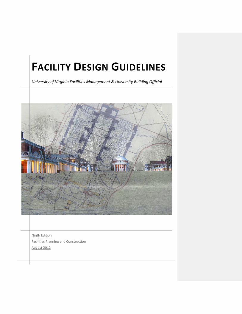
FACILITY DESIGN GUIDELINES University of Virginia Facilities Management & University Building Official
Ninth Edition
Facilities Planning and Construction
August 2012

THIS PAGE INTENTIONALLY LEFT BLANK

INTRODUCTION i
Facility Design Guidelines
University of Virginia Facilities Management & University Building Official
The University of Virginia Facilities Design Guidelines is intended for the use of architects, landscape architects, and engineers involved in the preparation of construction documents for the University of Virginia. The Guidelines are a reference for University facilities project managers and other personnel whose responsibilities include implementing institutional lessons-learned through design, construction and in-house services. The Guidelines provide procedural and technical requirements broadly applicable to all design and construction. As part of the contractual agreement between the design professional and the University, conscientious application of the Guidelines is a tool to expedite the design and construction process in a cooperative, partnering effort. In like manner, Facilities Management personnel and the Office of the University Building Official are responsible for executing the intent of the Guidelines. The format of this eighth edition of the University of Virginia Facilities Design Guidelines is intended to be user friendly, with an emphasis on pre-design understanding for a partnering effort between architect, engineer, end user, and a variety of facilities personnel under the responsibility of the University Project Manager. The Office of the University Building Official is responsible for ensuring these Guidelines are implemented. A table of contents precedes each of the categories and an index is provided. Periodic supplements to these Guidelines may be published and distributed to anyone on record as having a copy of the Guidelines. These Guidelines, and any added supplements, shall be followed for all University projects unless due process is used for waivers or modifications. It is intended that the Guidelines be incorporated into the design documents. The University of Virginia Facilities Design Guidelines has been prepared to guide and assist architectural
and engineering consultants and Facilities Management staff in the planning, design and preparation of design documents for construction and renovation of University facilities. The Guidelines in this publication identify specific or unique standards and requirements for University projects and the "lessons learned" from past University projects. As such, the Guidelines supplement and are in addition to mandatory codes, industry standards or other authoritative resources applicable under the laws of the Commonwealth of Virginia and the Federal Government. There may be particular project circumstances that, in the judgment of the Architect or Engineer, warrant alternatives to these Guidelines. Such recommendations are welcome and will be conscientiously considered. However, unless the University CFO gives special approval for alternatives prior to implementation, the Architect and/or Engineer must comply with the Guidelines as stated in this publication. Recommendations are welcome from users for additions and modifications. Please submit any comments to the Director, Facilities Planning and Construction.

THIS PAGE INTENTIONALLY LEFT BLANK ii
TABLE OF CONTENTS
GR 1 GENERAL REQUIREMENTS ......................................................................... 3
GR 1.1 APPLICATION ....................................................................................................................................... 3
GR 1.2 DEFINITIONS/TERMS ........................................................................................................................... 3 GR 1.2.1 UNIVERSITY OF VIRGINIA (UNIVERSITY) GROUNDS ............................................................................... 3 GR 1.2.2 ARCHITECT/ENGINEER ........................................................................................................................... 4 GR 1.2.3 UNIVERSITY PROJECT MANAGER/CONSTRUCTION ADMINISTRATION MANAGER ............................... 4
GR 1.3 DOCUMENTS ....................................................................................................................................... 4
GR 1.4 PROFESSIONAL LIABILITY INSURANCE ................................................................................................. 5
GR 1.5 PARTNERING ....................................................................................................................................... 5 GR 2 ACCESSIBILITY ........................................................................................... 6
GR 2.1 DESIGN STANDARDS FOR ACCESSIBILITY ............................................................................................. 6 GR 2.1.1 ABBREVIATIONS ..................................................................................................................................... 6 GR 2.1.2 DESIGN STANDARDS FOR ACESSIBILITY AND USABILITY ........................................................................ 6 GR 2.1.3 CONFLICTING STANDARDS ..................................................................................................................... 7 GR 2.1.4 CLARIFICATIONS FOR UNIVERSITY OWNED BUILDINGS ......................................................................... 7 GR 2.1.5 ELEVATOR ACCESS ................................................................................................................................. 7 GR 2.1.6 STAIRS .................................................................................................................................................... 7 GR 2.1.7 UNIVERSITY COMPLIANCE ..................................................................................................................... 7
GR 3 CODES AND REVIEWS ................................................................................ 8
GR 3.1 CODES AND REGULATIONS .................................................................................................................. 8 GR 3.1.1 LIFE SAFETY CODE .................................................................................................................................. 9 GR 3.1.2 OTHER CODE REQUIREMENTS ............................................................................................................... 9 GR 3.1.3 CODE IMPLEMENTATION ....................................................................................................................... 9 GR 3.1.4 NEW WORK .......................................................................................................................................... 10 GR 3.1.5 REACTIVATED PROJECTS ...................................................................................................................... 10 GR 3.1.6 MODIFICATIONS TO CODE REQUIREMENTS ........................................................................................ 10 GR 3.1.7 USE GROUP CLASSIFICATIONS ............................................................................................................. 10
GR 3.2 CAPITAL OUTLAY REQUIREMENTS ..................................................................................................... 11
GR 3.3 REVIEWS AND APPROVALS ................................................................................................................ 11
GR 3.4 OFFICE OF THE UNIVERSITY BUILDING OFFICIAL (UBO) ...................................................................... 13
GR 3.5 OFFICE OF THE ARCHITECT FOR THE UNIVERSITY (OAU) .................................................................... 14
GR 3.6 UNIVERSITY LANDSCAPE ARCHITECT ................................................................................................. 15
GR 3.7 ART AND ARCHITECTURAL REVIEW BOARD (AARB) ........................................................................... 15

GR 3.8 VIRGINIA DEPARTMENT OF HISTORIC RESOURCES (DHR) .................................................................. 15
GR 3.9 BOARD OF VISITORS (BOV) ................................................................................................................ 16
GR 3.10 PROJECT STEERING COMMITTEE ........................................................................................................ 16
GR 3.11 FACILITIES MANAGEMENT ................................................................................................................. 16
GR 3.12 ARBORETUM AND LANDSCAPE COMMITTEE ..................................................................................... 17
GR 3.13 INFORMATION TECHNOLOGY & COMMUNICATIONS (ITC) ................................................................ 17
GR 3.14 OFFICE OF ENVIRONMENTAL HEALTH AND SAFETY (OEHS) ............................................................... 17
GR 3.15 SPECIAL PROCEDURES FOR ASBESTOS ABATEMENT .......................................................................... 18 GR 3.15.1 GENERAL ASBESTOS REQUIREMENTS ............................................................................................. 18 GR 3.15.2 ASBESTOS REMOVAL ....................................................................................................................... 19 GR 3.15.3 USE OF ASBESTOS OR ASBESTOS CONTAINING MATERIALS ........................................................... 20 GR 3.15.4 REMOVAL AND REPLACEMENT OF SPRAYED-ON FIREPROOFING................................................... 20 GR 3.15.5 ASBESTOS RELATED WORK INSURANCE REQUIREMENTS ............................................................... 20 GR 3.15.6 CONFLICT OF INTEREST POLICIES .................................................................................................... 21
GR 3.16 SPECIAL PROCEDURES FOR LEAD-BASED PAINT ABATEMENT ............................................................................... 21
GR 3.17 BUILDING PERMITS ............................................................................................................................ 23 GR 4 DESIGN STANDARDS AND REQUIREMENTS ............................................. 25
GR 4.1 PRE-DESIGN CONFERENCE ................................................................................................................. 25
GR 4.2 DRAWINGS AND SPECIFICATIONS ...................................................................................................... 25
GR 4.3 VIVARIUMS ........................................................................................................................................ 25
GR 4.4 EMERGENCY GENERATORS & FUEL BURNING EQUIPMENT ................................................................ 25
GR 4.5 STORMWATER ................................................................................................................................... 27 GR 4.5.1 CHESAPEAKE BAY PROGRAM ............................................................................................................... 28
GR 4.6 STORMWATER MANAGEMENT/EROSION & SEDIMENT CONTROL ....................................................................... 28 GR 4.6.1 LAND LESS THAN ONE ACRE ................................................................................................................ 28 GR 4.6.2 LAND GREATER THAN ONE ACRE ......................................................................................................... 28 GR 4.6.3 CALCULATION OF NET CHANGE ........................................................................................................... 28 GR 4.6.4 PLANS AND SPECIFICATIONS................................................................................................................ 29
GR 5 FUNCTIONAL AND SPACE PLANNING REQUIREMENTS ............................. 31
GR 5.1 SPACE GUIDELINES ............................................................................................................................ 31 GR 5.1.1 OFFICE SPACE GUIDELINES AND ALLOCATION STANDARDS BACKGROUND ....................................... 31 GR 5.1.2 OFFICE GUIDELINES AND ALLOCATION STANDARDS ........................................................................... 32 GR 5.1.3 OFFICE GUIDELINES ............................................................................................................................. 32 GR 5.1.4 OFFICE ALLOCATION STANDARDS ....................................................................................................... 33
GR 5.2 SPECIAL BUILDING PLANNING REQUIREMENTS ................................................................................. 49 GR 5.2.1 BUILDING EFFICIENCY RATIOS ............................................................................................................. 49 GR 5.2.2 MINIMUM DESIGN LOADINGS FOR BUILDINGS ................................................................................... 49 GR 5.2.3 ROOM NUMBER ASSIGNMENT PROCEDURE ....................................................................................... 49 GR 5.2.4 LIFE, RESEARCH AND FACILITIES FIRE PROTECTION ............................................................................. 50 GR 5.2.5 LACTATION ROOM DESIGN .................................................................................................................. 50 GR 5.2.6 CONFINED SPACE REQUIREMENTS ...................................................................................................... 51 GR 5.2.7 FALL HAZARDS ..................................................................................................................................... 51 GR 5.2.8 HAZARDOUS WASTE STORAGE ............................................................................................................ 52
GR 5.3 SECURITY ........................................................................................................................................... 52 GR 5.3.1 DESIGN FOR CRIME PREVENTION ........................................................................................................ 52 GR 5.3.2 OFFICE OF EMERGENCY PREPAREDNESS ............................................................................................. 53 GR 5.3.3 BUILDINGS AND STRUCTURES ............................................................................................................. 53 GR 5.3.4 SECURITY SYSTEMS .............................................................................................................................. 55 GR 5.3.5 SURVEILLANCE CAMERA SYSTEMS....................................................................................................... 55 GR 5.3.6 ON ALERT ELECTRONIC MESSAGE BOARDS ......................................................................................... 56 GR 5.3.7 ELECTRONIC ACCESS CONTROLS .......................................................................................................... 56
GR 5.4 Not Used. .......................................................................................................................................... 61 GR 5.3.8 EMERGENCY TELEPHONES ................................................................................................................... 61
GR 5.5 BUILDING SYSTEMS ACCESS AND EQUIPMENT .................................................................................. 61
GR 5.6 INFORMATION TECHNOLOGY & COMMUNICATIONS (ITC) ................................................................ 62
GR 5.7 CUSTODIAL ROOMS ........................................................................................................................... 63
GR 5.8 UVA RECYLING SPACE GUIDELINES .................................................................................................... 64
GR 5.9 BUILDING DEDICATION PLAQUES ...................................................................................................... 65 GR 6 SITE AND SITE PLANNING REQUIREMENTS .............................................. 66
GR 6.1 SITING AND RELATIONSHIP TO CONTIGUOUS SITES ........................................................................... 66
GR 6.2 MINIMUM STANDARDS FOR PARKING SPACES .................................................................................. 66 GR 6.2.1 PARKING DECKS AND GARAGES UTILIZING SELF-PARKING .................................................................. 66 GR 6.2.2 PARKING LOTS UTILIZING SELF-PARKING ............................................................................................. 67
GR 6.3 POLICY FOR PARKING SPACE PLANNING ............................................................................................ 67
GR 6.4 BUILDING MATERIALS........................................................................................................................ 68
GR 6.5 SITE INVESTIGATION .......................................................................................................................... 68
GR 6.6 BUILDING CONSTRUCTION IN A FLOOD PLAIN ................................................................................... 68 GR 7 SCHEDULING AND CONSTRUCTION CONSTRAINTS .................................. 69
GR 7.1 ARCHITECT/ENGINEER RESPONSIBILITY ............................................................................................. 69
GR 7.2 NOISE, VIBRATION, AND DUST .......................................................................................................... 69
GR 8 POLICIES FOR CONSTRUCTION ................................................................ 71
GR 8.1 CONSTRUCTION POLICIES .................................................................................................................. 71 GR 8.1.1 ABUSIVE AND OFFENSIVE LANGUAGE* ............................................................................................... 71 GR 8.1.2 SEXUAL HARASSMENT* ....................................................................................................................... 71 GR 8.1.3 DRUG AND ALCOHOL USE .................................................................................................................... 71 GR 8.1.4 SMOKE-FREE WORKPLACE* ................................................................................................................. 71 GR 8.1.5 BUILDER’S RISK INSURANCE ................................................................................................................. 71 GR 8.1.6 CONFLICT OF INTEREST ........................................................................................................................ 72
GR 9 BIDDING REQUIREMENTS AND PROCEDURES .......................................... 73
GR 9.1 CONSTRUCTION DOCUMENTS ........................................................................................................... 73
GR 9.2 SEPARATE CONTRACTS & OWNER FURNISHED PRODUCTS ................................................................ 73 GR 10 CONSTRUCTION REQUIREMENTS AND PROCEDURES .............................. 74
GR 10.1 ARCHITECT/ENGINEER RESPONSIBILITY ............................................................................................. 74
GR 10.2 CONSTRUCTION BARRIERS ................................................................................................................ 74
GR 10.3 CONSTRUCTION PROCEDURES ........................................................................................................... 74
GR 10.4 REQUESTS FOR INFORMATION .......................................................................................................... 75
GR 10.5 PRECONSTRUCTION MEETINGS ......................................................................................................... 75
GR 10.6 SUBMITTALS ...................................................................................................................................... 76
GR 10.7 PROGRESS MEETINGS ........................................................................................................................ 76
GR 10.8 BILLING INSTRUCTIONS ..................................................................................................................... 76
GR 10.9 EXCAVATION PERMITS....................................................................................................................... 77 GR 10.9.1 ROCK EXCAVATION ......................................................................................................................... 77
GR 10.10 BLASTING .......................................................................................................................................... 78
GR 10.11 UTILITY AND BUILDING SYSTEM OUTAGES ........................................................................................ 78
GR 10.12 REMOVAL OR ABANDONMENT OF UTILITIES ..................................................................................... 79
GR 10.13 TEMPORARY UTILITIES ....................................................................................................................... 79 GR 10.13.1 TEMPORARY ELECTRICAL SERVICE .................................................................................................. 79
GR 10.14 MATERIAL AND EQUIPMENT ON SITE ................................................................................................ 80
GR 10.15 GEOTECHNICAL AND STRUCTURAL TESTING AND LABORATORY SERVICES ........................................ 80
GR 10.16 PRE-INSTALLATION CONFERENCES .................................................................................................... 80

GR 10.17 PROGRESSIVE CONSTRUCTION CLEANING ......................................................................................... 80
GR 10.18 CHANGE ORDERS ............................................................................................................................... 81
GR 10.19 RECORD DOCUMENT KEEPING ........................................................................................................... 81
GR 10.20 ELECTRONIC SUBMISSIONS ................................................................................................................ 82 GR 10.20.1 PREPARATION OF ELECTRONIC FILES FOR PRINTING ...................................................................... 82
GR 11 PROJECT CLOSE-OUT REQUIREMENTS ..................................................... 84
GR 11.1 FINAL CLEANING ................................................................................................................................ 84
GR 11.2 SITE RESTORATION ............................................................................................................................ 84
GR 11.3 OPERATION AND MAINTENANCE MANUALS/DATA ........................................................................... 84
GR 11.4 SPARE PARTS AND MAINTENANCE MATERIALS ................................................................................. 86
GR 11.5 PREVENTIVE MAINTENANCE SYSTEMS EQUIPMENT LISTS ................................................................. 86
GR 11.6 WARRANTIES AND GUARANTEES ...................................................................................................... 86
GR 11.7 BENEFICIAL OCCUPANCY/FINAL INSPECTION ..................................................................................... 86 HP 1 HISTORIC PRESERVATION ........................................................................ 91
HP 1.1 GENERAL INFORMATION ................................................................................................................... 91
HP 1.2 PRESERVATION GUIDELINES .............................................................................................................. 91 HP 1.2.1 CARE AND MAINTENANCE ................................................................................................................... 92 HP 1.2.2 ADAPTIVE USE OF BUILDINGS AND LANDSCAPES ................................................................................ 92
HP 1.3 BUILDINGS BY PRESERVATION PRIORITY ........................................................................................... 94
HP 1.4 ARCHAEOLOGICAL CONCERNS ........................................................................................................... 95 SW 1 SITEWORK GENERAL ............................................................................... 99
SW 1.1 INTRODUCTION ................................................................................................................................. 99
SW 1.2 DESIGN DOCUMENT REQUIREMENTS ................................................................................................ 99
SW 1.3 Not Used. ........................................................................................................................................ 100
SW 1.4 UTILITY TRENCH CUTS IN ROADWAY ............................................................................................... 100
SW 1.5 UNDERGROUND OR ABOVE GRADE PETROLEUM STORAGE TANKS .................................................................... 100
SW 1.6 OIL INTERCEPTORS .......................................................................................................................... 100 SW 2 SITE PREPARATION ................................................................................ 101

SW 2.1 MUD AND DIRT CONTROL................................................................................................................ 101
SW 2.2 PLANT PROTECTION ......................................................................................................................... 101
SW 2.3 EARTHWORK ................................................................................................................................... 101
SW 2.4 SITE CLEARING ................................................................................................................................. 103
SW 2.5 SITE DEMOLITION ............................................................................................................................ 103
SW 2.6 SOIL TREATMENT ............................................................................................................................. 103 SW 3 SITE DEVELOPMENT .............................................................................. 104
SW 3.1. PLANTING ........................................................................................................................................ 104 SW 3.1.1 PLANT SELECTION .............................................................................................................................. 104 SW 3.1.2 SOIL PREPARATION ............................................................................................................................ 104 SW 3.1.3 PLANTING PROCEDURES .................................................................................................................... 104 SW 3.1.4 TREE PLANTING .................................................................................................................................. 105 SW 3.1.5 WARRANTY PERIOD ........................................................................................................................... 105
SW 3.2 SITE LIGHTING ................................................................................................................................. 105 SW 3.2.1 DESIGN REQUIREMENTS .................................................................................................................... 105 SW 3.2.2 ILLUMINATION REQUIREMENTS – HORIZONTAL ............................................................................... 105 SW 3.2.3 ILLUMINATION REQUIREMENTS – VERTICAL ..................................................................................... 106 SW 3.2.4 LIGHT FIXTURES AND DESIGN REQUIREMENTS ................................................................................. 106 SW 3.2.5 INSTALLATION REQUIREMENTS ......................................................................................................... 108
SW 3.3 SIGNAGE .......................................................................................................................................... 109
SW 3.4 PAVING AND CURBS ........................................................................................................................ 109 SW 3.4.1 PAVEMENT AT UTILITY TRENCHES ..................................................................................................... 110
SW 3.5 SIDEWALKS ...................................................................................................................................... 110 SW 3.5.1 CONCRETE SIDEWALKS ...................................................................................................................... 110 .............................................................................................................................................................................. 110 SW 3.5.2 BRICK SIDEWALKS .............................................................................................................................. 110
SW 3.6 EXTERIOR STEPS .............................................................................................................................. 111
SW 3.7 BICYCLE RACKS ................................................................................................................................ 111
SW 3.8 EMERGENCY TELEPHONES ............................................................................................................... 111 SW 3.8.1 EMERGENCY TELEPHONES ................................................................................................................. 111
SW 3.9 BENCHES .......................................................................................................................................... 112
SW 3.10 TRASH RECEPTACLES ....................................................................................................................... 112
SW 3.11 RECYCLING RECEPTACLES ................................................................................................................ 113
SW 3.12 BOLLARDS ........................................................................................................................................ 113 SW 3.12.1 METAL BOLLARD TYPE I ................................................................................................................. 113
SW 3.12.2 METAL BOLLARD TYPE II ................................................................................................................ 113 SW 3.12.3 WOOD BOLLARD ........................................................................................................................... 113
SW 3.13 DUMPSTER PADS ............................................................................................................................. 114 SW 4 SITE DRAINAGE SYSTEMS ...................................................................... 115
SW 4.1 BUILDING DRAINAGE ....................................................................................................................... 115 SW 4.1.1 LAND DISTURBANCE .......................................................................................................................... 115 SW 4.1.2 BUILDING AND ROOF DRAINAGE ....................................................................................................... 115
SW 4.2 STORM SEWER SYSTEMS ................................................................................................................. 115 SW 4.2.1 PIPING AND INSTALLATION ........................................................................................................... 115 SW 4.2.2 MANHOLES ........................................................................................................................................ 116 SW 4.2.3 INLETS AND STRUCTURES .................................................................................................................. 116
SW 5 SITE PIPING SYSTEMS ............................................................................ 118
SW 5.1 SEWER PIPING ................................................................................................................................. 118
SW 5.2 SEWER MANHOLES .......................................................................................................................... 118
SW 5.3 EXTERIOR DOMESTIC WATER AND CHILLED WATER PIPING ............................................................ 119 BE 1 BUILDING ENVELOPE ............................................................................. 123
BE 1.1 GENERAL INFORMATION ................................................................................................................. 123
BE 1.2 CONCRETE ....................................................................................................................................... 123 BE 1.2.1 GENERAL ............................................................................................................................................ 123 BE 1.2.2 FIBER REINFORCED CONCRETE .......................................................................................................... 124 BE 1.2.3 PLASTICIZER ADMIXTURE ................................................................................................................... 124 BE 1.2.4 ARCHITECTURAL CONCRETE .............................................................................................................. 124 BE 1.2.5 POST TENSIONED STRUCTURAL CONCRETE ....................................................................................... 124 BE 1.2.6 PENETRATIONS AND OPENINGS IN CONCRETE ................................................................................. 124 BE 1.2.7 ANCHOR BOLTS .................................................................................................................................. 125 BE 1.2.8 SLAB ON GRADE ................................................................................................................................. 125
BE 2 SUPERSTRUCTURE ................................................................................. 126
BE 2.1 GEOTECHNICAL DESIGN; EARTH PRESSURE LATERAL LOADS ............................................................ 126 BE 2.1.1 BUILDING FRAME DESIGN .................................................................................................................. 126 BE 2.1.2 GLOBAL STABILITY .............................................................................................................................. 126
BE 2.2 FLOOR AND ROOF CONSTRUCTION ................................................................................................. 126
BE 2.3 BEARING CONNECTIONS .................................................................................................................. 126
BE 2.4 ADDITION OF LOADS TO EXISTING STRUCTURES ............................................................................. 126
BE 2.5 SPRAYED-ON FIREPROOFING DESIGN & SPECIFICATION .................................................................. 127 BE 2.5.1 VALIDATION TESTING REQUIREMENTS.............................................................................................. 127

BE 2.5.2 REMOVAL AND REPLACEMENT OF SPRAYED-ON MATERIAL ............................................................. 128 BE 3 EXTERIOR ENCLOSURE........................................................................... 129
BE 3.1 EXTERIOR WALLS ............................................................................................................................. 129 BE 3.1.1 GENERAL ............................................................................................................................................ 129 BE 3.1.2 THERMAL & MOISTURE PROOFING ................................................................................................... 129 BE 3.1.3 BRICK SELECTION ............................................................................................................................... 129 BE 3.1.4 PARAPET WALLS................................................................................................................................. 130 BE 3.1.5 VENEER MASONRY ............................................................................................................................. 131 BE 3.1.6 MASONRY THRESHOLDS .................................................................................................................... 131 BE 3.1.7 MORTAR ............................................................................................................................................. 131 BE 3.1.8 WATER REPELLANT COATINGS .......................................................................................................... 131 BE 3.1.9 MASONRY ACCESSORIES .................................................................................................................... 131 BE 3.1.10 CLADDING/SIDING ........................................................................................................................ 131 BE 3.1.11 FLASHING ...................................................................................................................................... 131 BE 3.1.12 SEALANTS, CAULKING AND SEALS ................................................................................................. 132 BE 3.1.13 PORTLAND CEMENT PLASTAR ....................................................................................................... 132
BE 3.2 EXTERIOR PAINTING ........................................................................................................................ 132 BE 3.2.1 EXTERIOR COLOR STANDARDS ........................................................................................................... 132 BE 3.2.2 PAINT REMOVAL ................................................................................................................................ 132 BE 3.2.3 LEAD BASED PAINT REMOVAL ........................................................................................................... 132
BE 3.3 EXTERIOR WINDOWS ....................................................................................................................... 133 BE 3.3.1 GENERAL ............................................................................................................................................ 133 BE 3.3.2 GLAZING/STORM SASH ...................................................................................................................... 133
BE 3.4 EXTERIOR DOORS ............................................................................................................................ 133 BE 3.4.1 GENERAL ............................................................................................................................................ 133 BE 3.4.2 METAL DOORS/FRAMES .................................................................................................................... 134 BE 3.4.3 WOOD DOORS ................................................................................................................................... 134
BE 4 ROOFING ............................................................................................... 135
BE 4.1 ROOFING POLICY ............................................................................................................................. 135 BE 4.1.1 GENERAL ............................................................................................................................................ 135 BE 4.1.2 ROOFING ABBREVIATIONS ................................................................................................................. 135 BE 4.1.3 EXISTING ROOFING SYSTEMS ............................................................................................................. 135 BE 4.1.4 OWNER’S ROOFING INSPECTION ....................................................................................................... 136 BE 4.1.5 ROOFING CONFERENCES ................................................................................................................... 136 BE 4.1.5.1 PRE-PROPOSAL/PRE-BID CONFERENCE ......................................................................................... 137 BE 4.1.5.2 PRE-ROOFING CONFERENCE ......................................................................................................... 137 BE 4.1.6 GUARANTEES ..................................................................................................................................... 137 BE 4.1.7 NRCA ROOFING AND WATERPROOFING MANUAL ............................................................................ 139 BE 4.1.8 SMACNA ARCHITECTURAL SHEET METAL MANUAL .......................................................................... 139 BE 4.1.9 PROCUREMENT OF ROOFING SYSTEMS ............................................................................................. 139 BE 4.1.10 MATERIALS CERTIFICATION .......................................................................................................... 139 BE 4.1.11 SYSTEM EVALUATION.................................................................................................................... 140 BE 4.1.12 FINAL INSPECTION......................................................................................................................... 140
BE 4.2 ROOFING SYSTEMS .......................................................................................................................... 140

BE 4.2.1 LOW-SLOPE ROOFS AND ACCEPTABLE ROOFING SYSTEMS ............................................................... 140 BE 4.2.1.8 LOW-SLOPE MEMBRANES ............................................................................................................. 143 BE 4.2.2 STEEP-SLOPE ROOFING AND ACCEPTABLE ROOFING SYSTEMS ......................................................... 143 BE 4.2.2.1 STEEP-SLOPE MATERIALS .............................................................................................................. 144 BE 4.2.3 VEGETATIVE ROOF SYSTEMS ............................................................................................................. 145 BE 4.2.4 STEEL ROOF DECK .............................................................................................................................. 149 BE 4.2.5 BLOCKING AND MISCELLANEOUS CARPENTRY .................................................................................. 149 BE 4.2.6 UNACCEPTABLE ROOFING SYSTEMS .................................................................................................. 149
BE 4.3 ROOF DRAINAGE, GUTTER AND DOWNSPOUTS ............................................................................... 150
BE 4.4 ROOF SPECIALTIES AND ACCESSORIES ............................................................................................. 151 BE 5 ROOF EQUIPMENT AND OPENINGS ....................................................... 152
BE 5.1 ROOFTOP EQUIPMENT .................................................................................................................... 152
BE 5.2 ROOF HATCHES ................................................................................................................................ 152
BE 5.3 SKYLIGHT STRUCTURES/CLERESTORY WINDOWS ............................................................................ 152 INT 1 INTERIORS –GENERAL INFORMATION ................................................... 156
INT 1.1 DESIGN CRITERIA ............................................................................................................................. 156
INT 1.2 FINISH CRITERIA .............................................................................................................................. 156 INT 2 INTERIORS - CONSTRUCTION ................................................................. 157
INT 2.1 PARTITIONS ..................................................................................................................................... 157 INT 2.1.1 GENERAL ............................................................................................................................................ 157 INT 2.1.2 FIRE RATED ASSEMBLIES AND FIRE STOPPING .................................................................................. 157 INT 2.1.3 MOVEABLE PARTITIONS ..................................................................................................................... 157 INT 2.1.4 GLAZING ............................................................................................................................................. 158
INT 2.2 INTERIOR DOORS ............................................................................................................................. 158 INT 2.2.1 GENERAL ............................................................................................................................................ 158 INT 2.2.2 LOCKSETS ........................................................................................................................................... 158 INT 2.2.3 CLOSERS ............................................................................................................................................. 159 INT 2.2.4 STOPS ................................................................................................................................................. 160 INT 2.2.5 HINGES ............................................................................................................................................... 160 INT 2.2.6 Kick Plates .......................................................................................................................................... 160 INT 2.2.7 HEALTH SYSTEM DOOR LOCKING HARDWARE ASSOCIATED WITH ELECTRONIC ACCESS CONTROL . 160
INT 2.3 INTERIOR SPECIALTIES ..................................................................................................................... 161 INT 2.3.1 FIRE EXTINGUISHER CABINETS AND EXTINGUISHERS ........................................................................ 161 INT 2.3.2 INTERIOR SIGNAGE ............................................................................................................................ 161 INT 2.3.3 TOILET AND BATH ACCESSORIES........................................................................................................ 162 INT 2.3.4 TOILET PARTITIONS ............................................................................................................................ 162 INT 2.3.5 WALL AND CORNER GUARDS ............................................................................................................. 163 INT 2.3.6 CHALKBOARDS ................................................................................................................................... 163 INT 2.3.7 WARDROBES, LOCKERS AND COAT CLOSETS ..................................................................................... 163

INT 2.3.8 CUBICLE CURTAINS ............................................................................................................................ 163 INT 3 INTERIORS - STAIRWAYS ....................................................................... 164
INT 3.1 TREAD AND RISER CONSTRUCTION .................................................................................................. 164 INT 4 INTERIOR FINISHES ................................................................................ 165
INT 4.1 WALL FINISHES ................................................................................................................................ 165 INT 4.1.1 GYPSUM BOARD ................................................................................................................................ 165 INT 4.1.2 PAINT SELECTION AND COLOR........................................................................................................... 165 INT 4.1.3 WALL COVERINGS .............................................................................................................................. 165
INT 4.2 FLOOR FINISHES............................................................................................................................... 166 INT 4.2.1 CONCRETE FLOOR .............................................................................................................................. 166 INT 4.2.2 CERAMIC TILE ..................................................................................................................................... 166 INT 4.2.3 QUARRY TILE ...................................................................................................................................... 166 INT 4.2.4 HARDWOOD FLOORING ..................................................................................................................... 166 INT 4.2.5 RESILIENT FLOORING ......................................................................................................................... 166 INT 4.2.6 RESILIENT BASE .................................................................................................................................. 167 INT 4.2.7 CARPET ............................................................................................................................................... 167
INT 4.3 CEILING FINISHES ............................................................................................................................. 167 INT 4.3.1 GENERAL ............................................................................................................................................ 167 INT 4.3.2 SUSPENDED ACOUSTICAL TILE ........................................................................................................... 167
BSRV 1 BUILDING SERVICES GENERAL ......................................................... 172
BSRV 1.1 INTRODUCTION ............................................................................................................................... 172
BSRV 1.2 CONNECTIONS TO MECHANICAL, PLUMBING, ELECTRICAL AND CIVIL UTILITIES .............................. 172
BSRV 1.3 METERING UTILITIES ........................................................................................................................ 173
BSRV 1.4 AESTHETIC CONCERNS ..................................................................................................................... 173
BSRV 1.5 IDENTIFICATION .............................................................................................................................. 173
BSRV 1.6 HAZARDOUS MATERIALS AND FUME HOODS .................................................................................. 174
BSRV 1.7 SOUND PRESSURE LEVEL REQUIREMENTS ....................................................................................... 174
BSRV 1.8 VIBRATION AND SOUND ISOLATION REQUIREMENTS ..................................................................... 174
BSRV 1.9 CUSTODIAL ROOMS ......................................................................................................................... 174
BSRV 1.10 OPERATIONS AND MAINTENANCE MANUALS ................................................................................. 174
BSRV 1.11 COMMISSIONING ............................................................................................................................ 175 BSRV 1.11.1 DESIGN PHASE ............................................................................................................................... 175 BSRV 1.11.2 SUBMITTAL REVIEW AND CONSTRUCTION PHASES...................................................................... 175 BSRV 1.11.3 STARTUP AND CLOSE OUT PHASE ................................................................................................. 176
BSRV 1.12 TRAINING AND DEMONSTRATION OF SYSTEMS .............................................................................. 178
BSRV 1.13 CLOSE -OUT ..................................................................................................................................... 178 BSRV 2 VERTICAL TRANSPORTATION .......................................................... 179
BSRV 2.1 ACCESSIBILITY FOR THE DISABLED ................................................................................................... 179
BSRV 2.2 ELEVATORS ...................................................................................................................................... 179 BSRV 2.2.1 ELEVATOR MACHINE ROOMS AND PITS ....................................................................................... 179 BSRV 2.2.2 CONTROL SYSTEMS ....................................................................................................................... 180 BSRV 2.2.3 DIAGNOSTIC REQUIREMENTS ....................................................................................................... 180 BSRV 2.2.4 WARRANTY SERVICE REQUIREMENTS .......................................................................................... 180 BSRV 2.2.5 FINAL ACCEPTANCE ....................................................................................................................... 180 BSRV 2.2.6 ELEVATOR TYPES AND COMPONENTS .......................................................................................... 181 BSRV 2.2.7 ELEVATOR CAB SIZE ....................................................................................................................... 181 BSRV 2.2.8 AUTOMATIC POWER DISCONNECTION ......................................................................................... 181
BSRV 2.3 OTHER VERTICAL TRANSPORTATION ............................................................................................... 182 BSRV 2.3.1 DUMBWAITERS ............................................................................................................................. 182
BSRV 3 PLUMBING ...................................................................................... 183
BSRV 3.1 DOMESTIC WATER ........................................................................................................................... 183 BSRV 3.1.1 WATER SUPPLY AND TREATMENT ................................................................................................ 183 BSRV 3.1.2 DOMESTIC WATER METERING ...................................................................................................... 183 BSRV 3.1.3 DOMESTIC HOT WATER ................................................................................................................ 184
BSRV 3.2 MATERIALS ...................................................................................................................................... 184 BSRV 3.2.1 IDENTIFICATION ............................................................................................................................ 185
BSRV 3.3 WATER DISTRIBUTION ..................................................................................................................... 185
BSRV 3.4 STORM AND SANITARY WASTE SYSTEMS ........................................................................................ 186
BSRV 3.5 SPECIAL PLUMBING SYSTEMS .......................................................................................................... 186 BSRV 3.5.1 PIPING SYSTEMS FOR GASES ......................................................................................................... 186 BSRV 3.5.2 EMERGENCY SHOWER AND EYEWASH EQUIPMENT FOR LABORATORIES ................................... 187
BSRV 4 HEATING, VENTILATION, AND AIR CONDITIONING.......................... 188
BSRV 4.1 GENERAL ......................................................................................................................................... 188 BSRV 4.1.1 DESIGN PARAMETERS ................................................................................................................... 188 BSRV 4.1.2 CHEMICAL CLEANING & CHEMICAL WATER TREATMENT OF BOILERS & HVAC SYSTEMS ............ 192 BSRV 4.1.3 DISTRIBUTION ............................................................................................................................... 194 BSRV 4.1.4 TESTING AND BALANCING ............................................................................................................ 194 BSRV 4.1.5 METERS, GAUGES, INDICATORS AND THERMOSTATS .................................................................. 195 BSRV 4.1.6 CONTROL AIR ................................................................................................................................ 196 BSRV 4.1.7 PLANS AND SPECIFICATIONS ......................................................................................................... 196
BSRV 4.2 MECHANICAL LOCATION AND EQUIPMENT ..................................................................................... 196 BSRV 4.2.1 MECHANICAL ROOMS ................................................................................................................... 196
BSRV 4.2.2 CEILING ACCESS ............................................................................................................................. 198 BSRV 4.2.3 EQUIPMENT .................................................................................................................................. 198 BSRV 4.2.4 VIBRATION AND SOUND ISOLATION REQUIREMENTS .................................................................. 198
BSRV 4.3 HEATING .......................................................................................................................................... 199 BSRV 4.3.1 SOURCES ....................................................................................................................................... 199 BSRV 4.3.2 STEAM AND HOT WATER TUNNELS AND DISTRIBUTION SYSTEMS .............................................. 200 BSRV 4.3.3 MATERIALS .................................................................................................................................... 202 BSRV 4.3.4 CONTROLS ..................................................................................................................................... 204 BSRV 4.3.5 BUILDING DISTRIBUTION .............................................................................................................. 204
BSRV 4.4 VENTILATION ................................................................................................................................... 206 BSRV 4.4.1 SOURCES/OUTSIDE AIR ................................................................................................................. 206 BSRV 4.4.2 FIRE AND SMOKE DAMPERS.......................................................................................................... 206 BSRV 4.4.3 SMOKE CONTROL SYSTEMS .......................................................................................................... 207 BSRV 4.4.4 MATERIALS .................................................................................................................................... 209 BSRV 4.4.5 CONTROLS ..................................................................................................................................... 210 BSRV 4.4.6 DISTRIBUTION, GENERAL EXHAUST .............................................................................................. 210 BSRV 4.4.7 FUME HOODS AND LAB EXHAUST ................................................................................................. 212
BSRV 4.5 AIR CONDITIONING ......................................................................................................................... 213 BSRV 4.5.1 SOURCES ....................................................................................................................................... 213 BSRV 4.5.2 REFRIGERATION SYSTEMS ............................................................................................................. 214 BSRV 4.5.3 MATERIALS AND EQUIPMENT ....................................................................................................... 215 BSRV 4.5.4 CONTROLS ..................................................................................................................................... 216
BSRV 4.6 COOLING COIL CONDENSATE ........................................................................................................... 216 BSRV 4.6.1 REMOVAL ...................................................................................................................................... 217 BSRV 4.6.2 MATERIALS .................................................................................................................................... 217 BSRV 4.6.3 CONTROLS ..................................................................................................................................... 217 BSRV 4.6.4 BUILDING DISTRIBUTION .............................................................................................................. 217
BSRV 5 FIRE PROTECTION SYSTEMS ............................................................ 218
BSRV 5.1 GENERAL ......................................................................................................................................... 218 BSRV 5.1.1 FIRE PROTECTION INFORMATION ............................................................................................ 218
BSRV 5.2 FIRE PROTECTION SPRINKLERS ........................................................................................................ 218 BSRV 5.2.1 SPRINKLER HEAD DATABASE ......................................................................................................... 218 BSRV 5.2.2 FIRE SUPPRESSION SYSTEMS - SPRINKLERS .................................................................................. 219 BSRV 5.2.3 APPLICATION ................................................................................................................................. 221 BSRV 5.2.4 INSTALLATION, INSPECTION AND ACCEPTANCE ........................................................................... 221
BSRV 5.3 FIRE PUMPS ..................................................................................................................................... 221 BSRV 5.3.1 WORKING DRAWINGS ................................................................................................................... 222 BSRV 5.3.2 SPECIFICATIONS ............................................................................................................................ 223 BSRV 5.3.3 STANDPIPE AND HOSE SYSTEM ..................................................................................................... 224 BSRV 5.3.4 FIRE PROTECTION SPECIALTIES ..................................................................................................... 224
BSRV 5.4 PROTECTION DURING CONSTRUCTION ............................................................................................ 224 BSRV 6 ELECTRICAL SYSTEMS ...................................................................... 225
BSRV 6.1 SERVICE AND DISTRIBUTION ............................................................................................................ 225 BSRV 6.1.1 POWER .......................................................................................................................................... 225 BSRV 6.1.2 TRANSFORMERS AND PRIMARY SWITCHES .................................................................................. 225 BSRV 6.1.3 DISTRIBUTION ............................................................................................................................... 226
BSRV 6.2 BUILDING INTERIOR SYSTEMS ......................................................................................................... 230 BSRV 6.2.1 GENERAL ....................................................................................................................................... 230 BSRV 6.2.2 DEMOLITION ................................................................................................................................. 230 BSRV 6.2.3 PANELS, SWITCHGEAR AND TRANSFORMERS ............................................................................... 230 BSRV 6.2.4 ELECTRICITY METERING ................................................................................................................ 232 BSRV 6.2.5 CONDUITS AND WIRING ............................................................................................................... 232 BSRV 6.2.6 DEVICES ......................................................................................................................................... 233 BSRV 6.2.7 LIGHTING ....................................................................................................................................... 234 BSRV 6.2.8 MOTORS AND STARTERS ............................................................................................................... 236 BSRV 6.2.9 BUS DUCT INSTALLATIONS ............................................................................................................ 238 BSRV 6.2.10 LIGHTNING PROTECTION SYSTEMS ............................................................................................... 238
BSRV 6.3 SPECIAL SYSTEMS ............................................................................................................................ 238 BSRV 6.3.1 TELECOMMUNICATIONS ............................................................................................................... 238 BSRV 6.3.2 TELECOMMUNICATION CABLING STANDARDS ............................................................................. 239 BSRV 6.3.3 CABLE TELEVISION ......................................................................................................................... 239 BSRV 6.3.4 SECURITY ....................................................................................................................................... 240 BSRV 6.3.5 CLASS 2 AND 3 ELECTRICAL CABLES .............................................................................................. 240 BSRV 6.3.6 FIRE DETECTION AND ALARM SYSTEMS ........................................................................................ 240
BSRV 6.4 ELECTRICAL TESTING ........................................................................................................................ 244
BSRV 6.5 RECORD OR AS-BUILT DOCUMENTS ................................................................................................. 244 BSRV 7 ELECTRONIC MONITORING AND CONTROLS .......................................... 246
BSRV 7.1 GENERAL REQUIREMENTS ............................................................................................................... 246 BSRV 7.1.1 APPLICATION ................................................................................................................................. 246 BSRV 7.1.2 BIDDING PROCEDURES .................................................................................................................. 247 BSRV 7.1.3 DIVISION 17 GUIDELINES FOR DEVELOPING DIVISION 17 SPECIFICATIONS .................................. 248
APPENDIX A – FIGURES ................................................................................... 252
APPENDIX B –ROOF INSPECTION FORMS AND PROCEDURES .......................... 282
APPENDIX C – UTILITY METERING REQUIREMENTS ......................................... 288
APPENDIX D - ELEVATORS ............................................................................... 292
APPENDIX E - SECURITY REFERENCES .............................................................. 307

THIS PAGE INTENTIONALLY LEFT BLANK 2
GR 1 GENERAL REQUIREMENTS 3
GR 1 GENERAL REQUIREMENTS
GR 1.1 APPLICATION
University of Virginia Facilities Design Guidelines shall apply to all design projects unless specifically waived by the Chief Facilities Officer. Facilities Design Guidelines are to be incorporated into the design and construction documents. Exceptions to the Guidelines shall be submitted by the Project Manager to the Chief Facilities Officer through the University Building Official with a “Determinations and Finding Report”.
GR 1.2 DEFINITIONS/TERMS
GR 1.2.1 UNIVERSITY OF VIRGINIA (UNIVERSITY) GROUNDS “Grounds” - Comprised of North Grounds, West Grounds, Central Grounds and the Jefferson Park Avenue precinct of the University of Virginia Health System as illustrated in Figure 1. “Historic Grounds” - Area bounded by Jefferson Park Avenue, McCormick Road, University Avenue, Hospital Drive (up to and including facades of Cobb Hall, McKim Hall, Barringer Wing and Old Medical School buildings along Hospital Drive), as illustrated in Figure 2. Portions of Rugby Road are also designated as a historic district.
"The Academical Village"- Original Jefferson designed buildings and grounds, including the land bounded by McCormick Road, University Avenue, Hospital Drive and including the South Lawn in front of Cabell Hall, as illustrated in Figure 3.
“Central Grounds” - The area bounded by Emmet Street, University Avenue, Hospital Drive and Jefferson Park Avenue, is the Historic Grounds and the Academic Village, as illustrated in Figure 4.
“University of Virginia Health System (Health System) Area” – The School of Medicine, School of Nursing, Health Sciences Library, and Medical Center are components of the Jefferson Park Avenue precinct bounded by Hospital Drive, University Avenue, Jefferson Park Avenue, the CSX Railroad, the Norfolk Southern Railroad, and Brandon Avenue. Additionally, the Health System includes the Kluge Children’s Rehabilitation Center located on U. S. 250 West near the U. S. 29 Bypass, the Moser Radiation Therapy Center at 2871 Ivy Road, U. S. 250 West, and other off-site clinical facilities, as illustrated in Figures 5, 5a, and 5b.
GR 1 GENERAL REQUIREMENTS 4
GR 1.2.2 ARCHITECT/ENGINEER "Architect/Engineer (A/E)" as used in these Guidelines is the Architect or Engineer of record who contracts with the University as the prime design professional to provide architectural or engineering services for a project. The term includes any associates or consultants employed by the A/E of record in the provision of project design services.
GR 1.2.3 UNIVERSITY PROJECT MANAGER/CONSTRUCTION ADMINISTRATION MANAGER “Project Manager (PM)” as used in these Guidelines, unless otherwise defined, is synonymous with “University of Virginia Project Manager”, the designated Facilities Management person responsible to the Building Committee and University administration for the management of project design and construction within the established scope, budget and schedule. The Project Manager is the University’s designated contact person for the A/E.
“Construction Administration Manager (CAM)” as used in these Guidelines, unless otherwise defined, is the Facilities Management person responsible to the Project Manager for administration of construction, project inspection, and coordination with other University persons or entities related to utilities, communications, and information technology.
Additional defining of roles related to these University representatives is incorporated in the Division 1 Template document Section 01000.1.2 “University Representatives” (Website: http://fmweb.virginia.edu/fpc/links.htm ).
GR 1.3 DOCUMENTS Conform to the CADD version currently in use by Facilities Management and confirm the mode of transmission prior to project initiation.
Contract bid documents are to be dated with the actual date of final submission incorporating the review comments by the Office of the University Building Official and other applicable University reviews.
All project specifications shall be provided in PDF format (preferred) or the most current version of Microsoft Word for Windows format.
Facilities Management’s base map is based on a set control datum. This control datum shall be used for all electronic mediums that pertain to mapping, civil and site work. Mapping shall be in accordance with National Map Accuracy Standards, based on Virginia State Plane Coordinate System, South Zone and North American Datum 1983 (NAD83). Vertical control is based on the North American Vertical Datum 1988 (NAVD88).

GR 1 GENERAL REQUIREMENTS 5
NAVD88 Control Monuments have been established in various locations on the University Grounds using this datum. All construction or survey work shall be performed based on the most recent established control.
Specific drawing requirements shall be in accordance with the most current version of Higher Education Capital Outlay Manual (“HECOM”).
GR 1.4 PROFESSIONAL LIABILITY INSURANCE Refer to HECOM for information pertaining to professional liability insurance.
GR 1.5 PARTNERING
Partnering is encouraged on all University projects. Projects over $5,000,000 construction cost shall have a formal partnering agreement, unless waived by the Chief Facilities Officer (CFO).
Refer to HECOM: http://fmweb.virginia.edu/fpc/links.htm.

GR 2 ACCESSIBILITY 6
GR 2 ACCESSIBILITY
GR 2.1 DESIGN STANDARDS FOR ACCESSIBILITY GR 2.1.1 ABBREVIATIONS
ADA Americans with Disabilities Act ATBCB Architectural and Transportation Barriers Compliance Board DOJ U. S. Department of Justice
GR 2.1.2 DESIGN STANDARDS FOR ACESSIBILITY AND USABILITY The following standards and regulations shall be used in planning and designing new construction, renovations or replacements for University projects on Commonwealth property: (1) Any standard in GR 2.1 that is more stringent than a standard promulgated in
and by the ADA.
(2) The ADA: Title II, Subtitle A, (and not Title III) of the Act applies to Commonwealth facilities.
(3) Department of Justice Final Rule on Title II of ADA-90, identified in the Federal
Register as 28 CFR Part 35.
(4) 2010 ADA Standards.
(5) Non-Discrimination Under State Grants and Programs: These regulations, promulgated by the Board for Rights of Virginians with Disabilities and effective on October 1, 1990, implement Va. Code §51.5-40.
(6) Van parking is required in new parking areas and, where feasible, renovated
parking construction.
(7) Automatic door openers are required at major entrances along accessible routes. See BUILDING ENVELOPE BE 3.4.1 Exterior Doors General.
(8) The use of accessibility approved lever-handled door hardware is required in
new construction and renovations without regard to the numbers of doors involved.
(9) Facilities shall be designed so that accessibility does not stand out or draw
attention to it when other architectural alternatives are available. As an example, restroom lavatories shall be of uniform design with all lavatories meeting accessibility standards rather than just one unit meeting the standards. This would not apply to toilet stalls, urinals, or water closets.
GR 2 ACCESSIBILITY 7
(10) In addition to application of 2010 ADA Standards, teaching and research laboratories shall have a minimum of five percent, but not less than one, work station for each type of facility (fume hood, bench, sink, etc.). Compliance may be achieved using readily adjustable modular casework and equipment.
(11) Platform lifts for the disabled are prohibited in new construction. The University
Subcommittee for Accessibility must approve use of platform lifts in renovation projects, where ramps are not feasible.
See BUILDING SERVICES BSRV 2.1 Accessibility for the Disabled, for elevator cab controls, hall call buttons and telephone requirements.
GR 2.1.3 CONFLICTING STANDARDS
Where standards conflict, the most stringent standard shall be used in designing accessible facilities. That is, the standard most favorable or advantageous to the disabled shall be used.
GR 2.1.4 CLARIFICATIONS FOR UNIVERSITY OWNED BUILDINGS
Accessible facilities must be provided at the completion of construction. Adaptable facilities do not meet the requirements for accessibility unless demonstrated to the University Building Official to be readily implemented on demand.
GR 2.1.5 ELEVATOR ACCESS
As clarification of 2010 ADA Standards §206.2.3, Accessible Routes, Multistory Buildings and Facilities, all passenger elevators shall be accessible to the disabled and multistory residential facilities shall include at least one accessible route to each floor level and each mezzanine in a building. Exception 4 does not apply to residential facilities.
GR 2.1.6 STAIRS
All stairways shall be accessible to the disabled.
GR 2.1.7 UNIVERSITY COMPLIANCE Where these Guidelines exceed code or legal requirements for accessibility, the Guidelines shall govern. Waivers for University accessibility Facility Design Guidelines requirements must be granted by the CFO by means of a request, coordinated by the Project Manager and submitted to the University Building Official’s office. A presentation to the University Subcommittee for Accessibility may be required.

GR 3 CODES AND REVIEWS 8
GR 3 CODES AND REVIEWS
GR 3.1 CODES AND REGULATIONS The following Codes and Regulations apply to University projects on Commonwealth property. When used In the Facility Design Guidelines, the word “Code” is defined as any of the following Codes and Regulations that are applicable. (1) VUSBC, Volume I (except Standards for the Disabled), latest edition, including
the referenced model Codes and standards adopted.
(2) The Americans with Disabilities Act, 1990: Title II, Subtitle A, (and not Title III) of the Act applies to all state owned buildings and structures. The accessibility standards to be used for State Owned Buildings and Buildings and Structures are the 2010 Standards for Accessible Design (2010 ADA Standards) published September 15, 2010, excluding the 2010 Standards for Public Accommodations and Commercial Facilities: Title III (Pages 15-30), and as clarified herein. The ADA Standards are available at www.ADA.gov.
(3) VUSBC, Volume II including the referenced model Codes and standards adopted.
(4) Virginia Public Building Safety Regulations for pre-1972 buildings.
(5) Industrialized Building and Mobile Home Safety Regulations.
(6) Liquefied Petroleum Gas Regulations.
(7) Amusement Device Regulations.
(8) Virginia Statewide Fire Prevention Code, including the referenced model Codes and standards adopted.
(9) Certification of Tradesmen Standards.
(10) Dept. of Conservation and Recreation (DCR) - Erosion and Sediment Control Regulations (VR 625-02-00).
(11) DCR- Stormwater Management Regulations (VR 215-02-00).
(12) Applicable Department of Health Regulations.
(13) Applicable DEQ, Water Division, Regulations.

GR 3 CODES AND REVIEWS 9
GR 3.1.1 LIFE SAFETY CODE The requirements of the Life Safety Code, NFPA 101, apply only to the University Hospital and clinical facilities accredited by the Joint Commission on Accreditation of Health Organizations (JCAHO) and accepting federal Medicare and Medicaid funds. In case of conflict, the most stringent requirements apply. Should there be a conflict between VUSBC that critically affects accreditation by JCAHO this will be resolved with the University Building Official. Though subject to confirmation in future years, for inpatient medical care facilities only, the National Fire Protection Association, Life Safety Code 101 2000 is applicable. If this should come into question it shall be determined in consultation with the University Building Official if a later edition has been adopted for application. The Virginia Uniform Statewide Building Code is divided into three stand-alone parts. Part I, the Virginia Construction Code contains regulations specific to the construction of new buildings and alterations, additions and change of occupancy in existing buildings and structures. The Virginia Construction Code (link provided on website http://fmweb.virginia.edu/fpc/links.htm) addresses amendments to the International Building Code.
GR 3.1.2 OTHER CODE REQUIREMENTS
Certain projects may be required to comply with other Codes or regulations, such as federal or special regulations of the Commonwealth. Those Codes may take precedence over the VUSBC, and the Accessibility and Energy Conservation Standards. All such Codes shall be clearly stated in the Preplanning Documents and displayed on title sheets of Preliminary Design and Construction Documents.
The mixing of Code requirements between two editions of the Code is not allowed without written authorization from the University Building Official. Code requirements in one section are often dependent upon conformance with requirements in other sections. BSL3 containment spaces shall conform to the latest edition of Biosafety in Microbiological and Biomedical Laboratories and the NIH BSL3 Design Polices and Guidelines.
GR 3.1.3 CODE IMPLEMENTATION
Typically, the VUSBC is adopted every three years. Such adoption incorporates specified editions of model Codes (such as 2003, 2006 International Building Code, etc.) along with Virginia modifications to these Codes. The Department of Housing and Community Development posts Notices/Announcements with the effective dates of VUSBC editions as well as the dates of referenced standards and amendments.

GR 3 CODES AND REVIEWS 10
GR 3.1.4 NEW WORK
The applicable code shall be the VUSBC edition in effect at the time Preliminary Designs are approved (using a HECO-5) and authorization is given to proceed with development of the Construction Documents.
If Preliminary Designs are approved during the four (4) months prior to the effective date of a new edition of the VUSBC, the applicable Code shall be designated by the University Building Official.
GR 3.1.5 REACTIVATED PROJECTS
Prior to reactivating a project that has been inactive for a period during which the effective Code has changed; the University Building Official shall determine which Code applies. The Plans and Specifications shall be revised as necessary to comply.
GR 3.1.6 MODIFICATIONS TO CODE REQUIREMENTS
If a modification to the VUSBC is thought to be necessary, the A/E shall request such modification in writing at the time preliminaries are submitted. The request shall clearly state the nature of the problem and the supporting rationale and justification for the modification. All requests to waive or grant a modification to the requirements of the VUSBC will be addressed to the University Building Official. Building code modifications, per the Virginia Construction Code, are to be directed to the University Building Official by the Project Manager using a prescribed Determinations and Findings Report for Code Modifications.
GR 3.1.7 USE GROUP CLASSIFICATIONS
The following guidance shall be used for buildings and structures at the University:
(1) Buildings for business training and vocational training shall be classified and
designed for the Use Group corresponding to the training taught.
(2) Academic buildings having classroom-type education functions (including associated professor/teacher office spaces) where large groups of students must change classes on a schedule shall include the following:
(a) Fire Protection Signaling System in the building (b) 72” minimum corridor widths in the classroom corridors (c) Occupant load for each space calculated based on VUSBC Chapter 10 for the
type of occupancy (not Use Group classification) of the space
(3) Buildings housing research, testing and science laboratories shall include a Fire Protective Signaling System.
GR 3 CODES AND REVIEWS 11
(4) Dormitories, Fraternity and Sorority Houses, and similar dwelling units with
sleeping accommodations shall provide one of the following:
(a) Written University policy that prohibits the use of these residences as lodging for persons/groups/occupants for periods less than 30 days, or
(b) Design that complies with the most stringent requirements of both R-1 (Hotels) and Group R-2 (Dormitory); exclusive of minimum required plumbing facilities (that remains Group R-2)
(5) Grounds buildings with other specific uses, doubtful uses, and mixed occupancy
uses shall be classified in accordance with appropriate sections of Chapter 3 of the VUSBC.
(6) Cabins, beach houses, lodges and similar dwelling units with sleeping
accommodations rented to family groups:
(a) Residences for rent less for than 30 days with a maximum occupant load of 16 shall comply with the requirements for Use Group R-3.
(b) Residences for rent for less than 30 days with a maximum occupant load of greater than 16 shall comply with the requirements for Use Group R-1.
GR 3.2 CAPITAL OUTLAY REQUIREMENTS
The University has delegated authority over its capital outlay construction program. See HECOM for details.
For projects funded by General Funds legislated by the Commonwealth of Virginia, the Project Manager shall advise the A/E, and others, of any pertinent requirements peculiar to specific legislation and/or funding. All projects, regardless of total project cost, are subject to the current edition of the HECOM found at the following website: http://www.fm.virginia.edu/fpc/hecom.htm.
HECOM and applicable Department of General Services (CO) forms related to contract documents are available from the following website: http://www.fm.virginia.edu/fpc/hecom.htm.
GR 3.3 REVIEWS AND APPROVALS
The following applicable Commonwealth of Virginia agency reviews will be coordinated through the Project Manager. All architectural and engineering consultants shall
GR 3 CODES AND REVIEWS 12
provide written comment responses to the Project Manager for distribution to respective review agencies as listed below:
Fire Safety reviews will be conducted by the University Review Unit for all new construction projects, projects with both additions and renovations, projects with a change of use, and all other renovation projects. The University Review Unit shall submit Capital Project ($1M+) review comments and Working Drawings to the appropriate Regional State Fire Marshal’s office for their use in inspection of these projects and record purposes.
By University policy all renovation projects are required to provide fire and life safety improvements up to ten percent (10%) of the construction cost or to the extent required by Code, whichever is greater.
Fire suppression, fire detection, and fire alarm Shop Drawings shall be reviewed and approved prior to the work being installed. Where a complete fire protection system is designed and shown on the Final Documents, the Drawings and/or Specifications shall state that deviations in materials, locations, configurations, or sizes proposed by the contractor are subject to being reviewed under the provisions of §26 of the Contract General Conditions as a “substitution”.
When the fire suppression, fire detection, and fire alarm systems are not complete on the Final Documents, then Shop Drawings or Submittal data shall first be reviewed and approved by the A/E. The reviewed documents, with any added notations by the A/E, shall be submitted to the University Building Official’s office for final review and approval.
The Project Manager shall arrange the following University review submissions, as applicable. Resulting review comments shall be provided through the Project Manager to the A/E. Office of the University Building Official Office of Emergency Preparedness Art and Architectural Review Board UVA Erosion & Sediment Control Program Department of Conservation and Recreation Department of Historic Resources Department of Health State Water Control Board Department of Air Pollution Control Department of Waste Management Architect for the University and the Board of Visitors. University Landscape Architect and Arboretum and Landscape Committee Master Planning Council Capital Project Steering Committee or appropriate end user (Requester) Facilities Space and Real Estate Management (Programming Phase) Accessibility Project Manager Police/Safety
GR 3 CODES AND REVIEWS 13
Information Technology and Communications Office of Insurance and Risk Management
A/E participation in presentations to the Commonwealth of Virginia agencies and University entities may be required as necessary to convey a full and appropriate understanding of the aesthetic and technical design. The above reviews and approvals, where required, shall be deemed part of basic services, applicable to all design projects at the University.
The following departments shall provide applicable review comments in parallel with the Office of the University Building Official. The Review Unit will endeavor to incorporate these review comments in their specific discipline reviews. All architectural and engineering consultants shall provide written comment response to the Project Manager for distribution to respective review agencies as listed below.
Facilities Management Operations & Maintenance Department (HVAC, fire systems, elevator, landscape, building services) Facilities Management Energy & Utilities Department (sustainability programs, Systems Control Center, recycling, environmental compliance, utility systems, power systems, chiller plants, heat plants) Facilities Management Health System Physical Plant Office of Emergency Preparedness University Police Department Environmental Health and Safety
See Figure 6 – Project Document Reproduction and Review Request Form.
GR 3.4 OFFICE OF THE UNIVERSITY BUILDING OFFICIAL (UBO) The University Building Official is the designated building official for University owned buildings, including Agency 209, University of Virginia Medical Center buildings, and Agency 246, University of Virginia College at Wise. The University Building Official is the authority having jurisdiction for the enforcement of the Virginia Uniform Statewide Building Code. See GENERAL REQUIREMENTS GR 3.17 Building Permits. The University Building Official is charged with granting modifications, and establishing rules and regulations as may be necessary to carry out its function as building official (See Management Agreement.) Under the provisions of the Management Agreement, UBO performs reviews of the University’s project Drawings and Specifications for conformance with the requirements of the VUSBC, Facility Design Guidelines, Management Agreement, and HECOM. In accordance with the provisions of the University Review Unit shall perform fire safety reviews for all projects involving new construction, additions, or renovations that involve a change of use of a facility. The responsible State Fire Marshal Office shall
GR 3 CODES AND REVIEWS 14
perform fire safety reviews for other renovations and conduct fire safety inspections of all construction. The University Review Unit reviews documents for compliance with the VUSBC and the University Facilities Design Guidelines during its normal review of capital outlay or other projects. Such review does not relieve A/E’s from responsibility for designing in accord with these standards and Federal Law. The Office of the University Building Official is responsible for the enforcement of the building code, compliance with the University Facilities Design Guidelines, and compliance with the HECOM. Review comments (including those on constructability in the long-term interest of the University) require responses by the A/E (and where applicable the Project Manager) per procedural requirements of the HECOM.
Any project involving the location, or relocation, of a fire department building connection, or the location, relocation, or modification of a fire alarm control panel shall be approved Fire Marshal for the City of Charlottesville or other appropriate jurisdiction for University of Virginia College at Wise, Blandy Farm, Oyster Anheuser-Bushe Coastal Research Center, and other University owned off-Grounds location. In addition the A/E and Project Manager shall consider identified site requirements for accessing building sites by appropriate firefighting equipment.
University projects on long term leased land at Mountain Lake Biological Station are reviewed accordingly with the above, but the authority having jurisdiction is the Building Official of Giles County.
For each design phase submission review one complete set of documents shall be submitted for each represented discipline (fire safety, civil-structural, architectural, mechanical and electrical) plus one set for the Facilities Management Resource Center. Where applicable, additional set(s) may be required for the Department of Conservation and Recreation for storm water management and/or soil erosion and sediment control reviews.
GR 3.5 OFFICE OF THE ARCHITECT FOR THE UNIVERSITY (OAU) The Architect for the University provides architectural and design oversight to the senior administration of the University and to the Board of Visitors to assure reciprocity between academic planning and the physical planning and design of University buildings and grounds, historic preservation, and sustainability. In this capacity, the Architect for the University is the principal participant in the institutional planning process, responsible for the University's Facilities Master Plan and area precinct studies, the architectural and landscape architectural design of all buildings, structures, landscape development, open space, plantings, site furnishings and above-ground utilities, and historic preservation. See also HP – HISTORIC PRESERVATION.

GR 3 CODES AND REVIEWS 15
The Architect for the University provides the architectural design criteria for each project determined to be applicable by that office, including significant or major interior spaces. The Architect for the University is a responsible party for review and approval of design during the pre-design study or Schematic Design and the Preliminary Design/Design Development stages. The Architect for the University serves as the chair of the Architectural Selection Committee for all Capital Outlay and other designated projects; and serves as a member on every appointed building committee. Refer to www.virginia.edu/architectsoffice/index.html for additional OAU information, including exterior signage standards under “Landscape Architecture”.
GR 3.6 UNIVERSITY LANDSCAPE ARCHITECT
The University Landscape Architect, of the Office of the Architect for the University, assures that projects conform to the University Master Plan and precinct plans, advises on (1) selection of consulting landscape architects, and (2) design of outdoor spaces, plant selection and tree staking. Specific criteria for brick paving patterns and use of bollards shall be verified with the University Landscape Architect. Exterior signage standards are available under Landscape Architecture at website http://www.virginia.edu/architectoffice/Disciplines.html. The University Landscape Architect reviews projects before any presentation to the Arboretum and Landscape Committee (See GENERAL REQUIREMENTS GR 3.12 Arboretum & Landscape Committee) and serves as liaison between the University Development Office, Facilities Management, and donors in selecting and placing memorial trees and benches.
GR 3.7 ART AND ARCHITECTURAL REVIEW BOARD (AARB) For projects as determined applicable by the HECOM, the Project Manager in consultation with the Architect for the University, shall schedule, and coordinate the presentations to the AARB. The A/E will participate in presentations typically made at the Schematic Design stage and at the Preliminary Design Development stage. There may also be occasions when presentations of working drawings will be required.
The AARB typically meets monthly. Scheduling can be critical to a project schedule.
GR 3.8 VIRGINIA DEPARTMENT OF HISTORIC RESOURCES (DHR)
In accordance with the Governor’s Executive Order Number Forty-Seven (1976), the University must submit all plans for demolition or significant alteration, remodeling,

GR 3 CODES AND REVIEWS 16
redecoration, restoration, and repairs that may basically alter the appearance of any state-owned registered historic landmark to the Virginia Department of Historic Resources for review and comments. For a list of the University’s properties considered to have historic significance, see HP 1 - HISTORIC PRESERVATION.
GR 3.9 BOARD OF VISITORS (BOV) The Buildings and Grounds Committee of the Board of Visitors of the University of Virginia reviews Capital Outlay Projects for design in compliance with the Vision Statement for the Planning and Design of the University of Virginia Buildings and Grounds. The Buildings and Grounds Committee approves the location and design of new buildings, additions, and significant renovations. Approvals are required for architectural design guidelines and Schematic Designs. The Architect for the University, in conjunction with the A/E and the Project Manager make presentations to the Buildings and Grounds Committee.
GR 3.10 PROJECT STEERING COMMITTEE The University appointed Project Steering Committee advises and gives direction to Facilities Management and to the A/E in the development of a capital outlay project, within established scope and available funding, from the inception of planning through design and completed construction. Further definition and explanations can be found in Facilities Management Directive 501J and Handbook available via the website: http://www.fm.virginia.edu/directives/
GR 3.11 FACILITIES MANAGEMENT Designated Facilities Management personnel review design/construction documents for compliance and integration with utility master planning and needs, monitoring of fire protection and building systems, institutional space management under applicable guidelines by the Commonwealth of Virginia, landscaping, and the incorporation of lessons learned with regard to HVAC maintenance, fire protection systems and overall building operations. Facilities Management is responsible for implementing University policies regarding safety, security, accessibility for the physically disabled and related matters of health, safety and the general welfare of the University. For information related to Facilities Management, visit the website: http://www.fm.virginia.edu .
GR 3 CODES AND REVIEWS 17
GR 3.12 ARBORETUM AND LANDSCAPE COMMITTEE The Arboretum and Landscape Committee seeks to promote and improve the University’s Grounds and gardens to enrich the learning and social experience for the academic community and visitors. Composed of faculty, students, and staff, the committee meets throughout the year to review all landscape and master plan proposals and advise the Office of the Architect for the University and Facilities Management. Liaison with the Arboretum and Landscape Committee consult with the University Landscape Architect. For additional information see the website http://www.virginia.edu/architectoffice/arboretumlandscape/
GR 3.13 INFORMATION TECHNOLOGY & COMMUNICATIONS (ITC) The University owns an integrated telephone and information technology cabling system managed by Information Technology and Communications (ITC), administered by the Vice President and Chief Information Officer. See BUILDING SERVICES BSRV 6.3.1 Telecommunications.
GR 3.14 OFFICE OF ENVIRONMENTAL HEALTH AND SAFETY (OEHS)
The Environmental Health and Safety Office advise the University on relevant standards which are above and beyond the code requirements to ensure safe and healthy workplace design. The University manages air emission permits, stormwater discharge permits, laboratory biosafety cabinet and chemical fume hood certification and other process exhaust systems, emergency safety equipment, handling and storage of hazardous materials, overview of the abatement of asbestos or lead containing materials, and related health and safety issues through the Office of Environmental Health and Safety (OEHS). Consultation with and review by OEHS is required for the design of all University projects. For additional requirements on stormwater permits see Facilities Management Directive 523 and SITEWORK SW 4 Site Drainage Systems.
By Virginia State law, all exterior construction projects (with a few exceptions) exceeding $500,000 in total project cost, require the completion, submission, and approval of an Environmental Impact Review (EIR) before construction begins. OEHS will make the determination as whether an EIR is required. The Project Manager is responsible for contacting the OEHS and providing the required information for the completion of the EIR by OEHS. The Virginia Department of Environmental Quality (DEQ) prepares a review of the EIR, communicates those results to the University and the Governor’s Office. Final project approvals are issued by the Governor’s Office. The DEQ requires a 60-day review period, however, additional time may be required if the DEQ requests additional information. See Facilities Management Directive 522 for

GR 3 CODES AND REVIEWS 18
additional requirements. Questions should be directed OEHS Environmental Compliance Officer at 434-982-4901 or 434-982-4911.
GR 3.15 SPECIAL PROCEDURES FOR ASBESTOS ABATEMENT GR 3.15.1 GENERAL ASBESTOS REQUIREMENTS
Buildings constructed prior to 1980 are presumed to have asbestos-containing materials (ACM) in materials including, but not limited to, asphalt and vinyl flooring, resilient floor covering, mastics, fibrous pipe insulations, caulking, roofing, flashings, bonding agents, coatings, and binders until such materials have been tested and found not to contain asbestos.
An estimated cost for asbestos abatement shall be included in the cost estimate supporting the construction budget or budget request when it is suspected or predetermined. For renovation/demolition/addition projects, including roofing materials, the University shall test for asbestos-containing materials (ACM) prior to submittal of the Preliminary Design. The asbestos survey/inspection report must be made available to the project A/E for information and use in preparing the project documents.
If asbestos-containing materials are found, the University shall have a licensed asbestos designer in concert with the A/E prepare an asbestos abatement plan and prepare or update the University Asbestos Management Plan as required by the University in compliance with Va. Code §2.2-1164. The Office of Environmental Health and Safety shall be required to mark up the Asbestos Management Plan to show the “As-Built” conditions resulting from its work to include areas where asbestos was abated, areas where asbestos was encapsulated, and areas where asbestos containing materials exist, but were left in place.
Based on the report of the asbestos survey/inspection report and the Asbestos Management Plan, the construction documents for renovation or addition projects shall indicate all locations where ACM have been found, where ACM are to be disturbed and where ACM are to remain. The asbestos survey/inspection report and the Asbestos Management Plan must be made available to the contractor(s) for demolition and for construction.
The demolition plan sheets and the architectural floor plan sheets for each floor shall also have an Asbestos Disclosure Statement indicating one of the following:
(1) “An asbestos inspection was performed and no asbestos-containing materials were
found. The asbestos survey/inspection report is available to the contractor(s) for demolition and for construction for his information.”
(2) “An asbestos inspection was performed and asbestos-containing materials were found
generally in the areas indicated. However, the Work in this Project is not intended to disturb the existing asbestos-containing materials. The asbestos survey/inspection

GR 3 CODES AND REVIEWS 19
report and the Asbestos Management Plan are available to the contractor(s) for demolition and for construction for his information.”
(3) “An asbestos inspection was performed and asbestos-containing materials were found
generally in the areas indicated. The asbestos survey/ inspection report is available to the contractor(s) for his information. The asbestos-containing materials shall be removed prior to any other Work being performed in these areas. The Asbestos Management Plan is included in the documents. The asbestos abatement contractor shall mark-up the Asbestos Management Plan to show the “As-Built” conditions resulting from its Work to include areas where asbestos was abated, areas where asbestos was encapsulated, and areas where asbestos containing materials exist but were left in place.”
(4) “An asbestos inspection was performed and asbestos-containing materials were found
generally in the areas indicated. The asbestos survey/inspection report and the Asbestos Management Plan are available to the contractor(s) for demolition and for construction for his information. Asbestos-containing materials shall not be disturbed in this Work except where specifically indicated and required for connections to utilities. Where such connections are required, the contractor shall have the obstructive and adjacent asbestos-containing materials removed by licensed asbestos contractor using approved procedures as specified. The asbestos-containing materials that are to remain and the new non asbestos-containing material shall be labeled accordingly. The asbestos abatement contractor shall mark-up the Asbestos Management Plan to show the “As-Built” conditions resulting from its Work to include areas where asbestos was abated, areas where asbestos was encapsulated, and areas where asbestos containing materials exist but were left in place.”
The A/E shall be responsible to the University for coordinating the design of the renovation/addition work with the asbestos abatement work in order to prevent conflicts, claims, and work stoppages.
GR 3.15.2 ASBESTOS REMOVAL
All ACM that will be disturbed as a result of a renovation/ demolition/addition project must be removed. The University shall have asbestos project specifications written by a Virginia licensed designer. The designer’s license number, name and signature shall appear at the beginning of the asbestos specifications.
The asbestos project specifications shall adhere to all current federal and Commonwealth regulations and policies.
The specifications shall include a copy of the Project specific asbestos inspection report and Asbestos Management Plan indicating the sampling of and analyses for all materials that will or may be disturbed or accessed by the project. The specifications shall include a section that covers project notification by the asbestos contractor to the United States EPA, Virginia OSHA, and Division of Air Pollution Control at least 20 days prior to the actual start of the asbestos Project.

GR 3 CODES AND REVIEWS 20
Asbestos drawings and specifications shall be submitted to the University Office of Environmental Health and Safety (OEHS) with the working drawings for review and approval.
The University has two contracting options for use in removal of asbestos from a structure although option (2) is the preferred method: (1) A separate contract for removal of the asbestos prior to renovation, demolition
or addition. (2) A contract where the abatement is an integral part of the renovation, addition
or demolition project in which the general contractor is licensed as an asbestos contractor or hires a licensed asbestos abatement Subcontractor to perform the work.
The Office of Environmental Health and Safety shall be required to mark up the Asbestos Management Plan to show the As-Built conditions resulting from its work to include areas where asbestos was abated, areas where asbestos was encapsulated, and areas where asbestos containing materials exist but were left in place.
GR 3.15.3 USE OF ASBESTOS OR ASBESTOS CONTAINING MATERIALS
The use of materials that contain asbestos shall be prohibited in any new construction or renovations.
GR 3.15.4 REMOVAL AND REPLACEMENT OF SPRAYED-ON FIREPROOFING
The A/E in consultation with the University shall verify early in the design phase with the appropriate State Fire Marshal the original purpose of the fireproofing material to be removed or replaced and what, if anything, must be done to restore the fire resistive characteristics. Plans and specifications shall be submitted to the State Fire Marshal, which will include any final construction documents, amendments/addenda, or change orders which may relate to the fire resistive characteristics of the structure. On a submittal to the State Fire Marshal, indicate the construction date, original and present uses, height in floors and feet, whether sprinkled and any other information that may assist the State Fire Marshal in his determination. If sprayed-on ACM is to be replaced, the University or its A/E shall also submit copies of the specifications for the intended replacement material and the bridging encapsulate specified by the asbestos Project designer for review. The bridging encapsulate must be correctly matched with the replacement material to ensure maximum bonding strength and intended fire rating integrity of the assembly and acceptable flame spread ratings.
GR 3.15.5 ASBESTOS RELATED WORK INSURANCE REQUIREMENTS
Asbestos inspectors, project designers and project monitors and their firms are required to provide evidence of Professional Liability/Errors and Omissions insurance, with asbestos coverage, in an amount not less than $1M. The University, its officers,

GR 3 CODES AND REVIEWS 21
employees, agents or any other person acting in an official capacity, temporarily or permanently, in the service of the Commonwealth, should also be named as additional insured persons.
§11(e) of the General Conditions of the Contract for Capital Outlay Projects requires the asbestos contractor or subcontractor, as the case may be, to name the A/E as an additional insured on the contractor’s liability insurance with asbestos coverage. Where the A/E for the renovation project is also a Virginia licensed asbestos designer and prepares the asbestos project drawings and specifications, the requirement of §11(d) to name the A/E as an insured party is waived.
GR 3.15.6 CONFLICT OF INTEREST POLICIES
The asbestos surveyor/inspector, the asbestos abatement designer, the University’s asbestos management plan author and any other person or firm hired by the University to provide consulting or inspection services on the project shall not be associated by any business or financial relationship to the asbestos abatement contractor.
Asbestos abatement contractors are not eligible to Propose/Bid on those particular projects for which the asbestos surveys, inspections, bulk sample analyses, project designs, or asbestos management plans were performed by individuals or firms employed by or financially affiliated with the contractors during the time period in which the inspections were conducted, samples analyzed or the project designs written.
Asbestos surveyors, asbestos abatement designers or asbestos abatement management plan authors shall not contract with the asbestos abatement contractor to provide services on the project.
Asbestos project inspector (project monitors) are not eligible to contract for project inspection work on a project if they are financially affiliated with or employed by the asbestos abatement contractor on any project. These services are to be directly contracted for by the University, and the monitoring personnel shall be accountable only to University officials.
All laboratories utilized for asbestos sampling analyses for project purposes shall have no direct business or financial relationship with the contractors conducting asbestos abatement activities.
GR 3.16 SPECIAL PROCEDURES FOR LEAD-BASED PAINT ABATEMENT Effective June 3, 1993 the U. S. Department of Labor’s interim final rule amends the Federal OSHA standards for occupational health and environmental controls in subpart D of 29 CFR part 1926, adding a new §1926.62 indicating protection requirements for construction workers exposed to lead. The entire rule is contained in the Federal Register Vol. 58, No. 84, May 4, 1993. The Virginia OSHA (VOSHA) regulations have subsequently adopted the federal regulations in total.

GR 3 CODES AND REVIEWS 22
The Virginia Department of Labor and Industry (DLI) established an emergency regulation in the May 27, 1996 Virginia Register requiring, among other things, that a permit be issued by DLI to the lead abatement contractor. This requirement is also stated in the General Conditions of the Construction Contract. When planning a renovation, demolition or addition project, the OEHS shall have the facility to be renovated, surveyed for lead-based paint (LBP) contamination and document all quantities and locations found.
When lead-based paint is suspected or pre-determined, an estimated cost for abatement shall be included in the cost estimate supporting the construction budget or budget request.
The construction documents for renovation or addition projects shall indicate all locations where lead-based paint is to be disturbed or to remain and shall also have a lead-based paint disclosure statement indicating one of the following:
(1) A lead-based paint inspection was performed and no lead-based paint was
found. (2) A lead-based paint inspection was performed and lead-based paint was found in
indicated areas. However, the work in this project is not intended to disturb existing lead-based paint.
(3) A lead-based paint inspection was performed and lead-based paint was found in the areas indicated. The lead-based paint shall be removed prior to any other work being performed in these areas.
(4) A lead-based paint inspection was performed and lead based paint was found in the areas indicated. Lead-based paint shall not be disturbed in this work except where specifically indicated and required for connections to utilities. Where such connections are required, contractor shall have the obstructive and adjacent lead-based paint removed by a licensed lead- based paint abatement contractor using approved procedures as required by VOSHA. The lead-based paint that remains and new non lead-based paint areas shall be labeled accordingly.
(5) A lead-based paint inspection was performed and lead-based paint was found in the areas indicated. The contractor shall be responsible for compliance with all requirements of the Virginia Occupational and Health Administration regulations regarding lead-based paint protection for workers.
If abatement and encapsulation is to be done by the general contractor, the A/E shall identify the type and location of all lead-based paint and notify the general contractor that this work is part of the contract for construction. Lead-based paint must be identified and the contractors notified that they must be in compliance with VOSHA requirements for worker safety. It shall be the general contractor’s responsibility to comply with the requirements of VOSHA.
The general contractor shall establish a schedule with the agency for abatement and containment in buildings that are to remain occupied during construction.
GR 3 CODES AND REVIEWS 23
Following removal of lead-based paint containing materials, additional TCLP tests in accordance with EPA guidelines shall be done on these materials to determine disposal requirements. TCLP tests of waste materials shall identify whether the material will be required to be disposed of as toxic waste or as ordinary construction debris. It shall be unlawful for materials identified as toxic waste to be disposed of with ordinary construction debris.
GR 3.17 BUILDING PERMITS
Construction of new buildings, additions, alterations or renovations on University (state-owned) property requires a building permit whether constructed by Virginia licensed contractors, Facilities Management personnel, when allowed by “self-service” by other University personnel. Facilities Management Directive 562D, or a subsequent update, describes the procedures applicable to building permits and project permits (under the “Annual Permit” authorization). This directive further defines construction related work that does not require a building or project permit. If there is a question as to applicability of a building permit or a project permit, consult with the Office of the University Building Official. Building permits are to be submitted by the Project Manager or appropriate Facilities Management staff person utilizing the current edition of the HECO-17 building permit form (http://fmweb.virginia.edu/fpc/links.htm). Submission of the HECO-17 shall be as complete as possible, including information provided by the A/E as required by HECOM. Contractors are responsible under Virginia law to not start construction without an approved building permit. Submit building permits electronically to [email protected] for University Building Official processing. Projects in the Health System require approval from the Director of Health System Physical Plant (HSPP) in addition to the Office of the University Building Official. HSPP projects in or affecting patient healthcare facilities require Infection Control Risk Assessment (ICRA) and Interim Life Safety Measures (ILSM) documentation as approved by HSPP. The Project Manager, or other responsible Facilities Management person, shall assure that HSPP has the ability to review the design documents (at each design phase as submitted to the University Review Unit). Properties under the ownership of the University of Virginia Real Estate Foundation or the Health Services Foundation require building permits for construction from the City of Charlottesville, County of Albemarle, or other applicable Building Official in whose jurisdiction the property is located. Design documents for these properties may, however, be subject to review for Facilities Design Guideline requirements and constructability by the University Review Unit if at a foreseen time the building will be acquired as a University owned and operated building. Construction projects at the Mountain Lake Biological Station are issued building permits by the Giles County Building Official. These projects are reviewed by the

GR 3 CODES AND REVIEWS 24
University Review Unit for compliance with the Facilities Design Guidelines and constructability.

GR 4 DESIGN STANDARDS AND REQUIREMENTS 25
GR 4 DESIGN STANDARDS AND REQUIREMENTS
GR 4.1 PRE-DESIGN CONFERENCE
The design process shall be expedited by arranging through the Project Manager to schedule a pre-design conference at the earliest practical date in the Preliminary Design phase. For atypical projects not warranting a Preliminary Design, this conference shall be scheduled upon the initiation of design.
The pre-design conference is intended to: (1) Clarify and expedite the required HECOM and University Building Official review
process and schedule; provide for dialogue on Facilities Design Guidelines, including waivers or modifications that may be applicable
(2) Establish University preferences for civil, mechanical, plumbing and electrical systems
(3) Identify roles of Facilities Management departments and designated personnel determine necessary phasing and/or relocation issues based on user needs
(4) Determine if the application of on-board reviews is beneficial to the project or the design consultants
GR 4.2 DRAWINGS AND SPECIFICATIONS
Demolition or renovation work, which occurs on the floor below or above the primary construction site, shall be shown sufficiently to convey the extent of work, effect on occupants, and construction restraints to maintain or maximize functional occupancy of the effected space.
GR 4.3 VIVARIUMS
Vivarium and other research or clinically related animal holding facilities are required to meet architectural, mechanical, electrical and plumbing standards established by the current edition of the Guide for the Care and Use of Laboratory Animals, Institute of Laboratory Animal Resources, Commission on Life Sciences, National Research Council, and National Academy Press, which can be found at www.nap.edu.
GR 4.4 EMERGENCY GENERATORS & FUEL BURNING EQUIPMENT
All fuel burning equipment including but not limited to furnaces, boilers and emergency generators require evaluation for inclusion in the University of Virginia Federal Title V Air Permit and for permitting as a new stationary source (9VAC5-80) as required by the U.S. EPA and the Virginia Department of Environmental Quality as managed by the University of Virginia Office of Environmental Health and Safety (OEHS). For OEHS to complete the environmental review and permit applications as required, the Project
GR 4 DESIGN STANDARDS AND REQUIREMENTS 26
Manager is to provide the Environmental Compliance Officer with the following information as it becomes available:
(1) Copy of the manufacturer’s specifications (2) Copy of any available emissions data from the manufacturer (3) Size/capacity (kW, hp or btu/hr) (4) Manufacturer, model number, and serial number (5) Fuel type (6) Fuel tank specifications (7) Generator/boiler and tank location (8) Installation completion date
The manufacturer’s specifications must be provided for each new piece of fuel burning equipment including emergency power generators before they are purchased. It is also important to notify OEHS in a timely fashion of any removal, replacement or modifications of any fuel burning equipment in order to maintain the University’s permit documentation accordingly. Contractor shall submit emissions certificate from the manufacturer documenting the air emissions performance. Generator fuel shall be Diesel or No. 2 fuel oil and shall meet the regulatory requirements. Specifically fuel shall meet the following specs: (1) < 15 ppm sulfur
(2) a minimum cetane index of 40 or a max aromatic content of 35% volume
GR 4 DESIGN STANDARDS AND REQUIREMENTS 27
Contactor shall provide a letter of certification from the fuel supplier with the shipment documenting that the fuel meets these requirements. A fuel certification shall include the following information:
(1) Name of supplier
(2) Date of fuel received
(3) Volume of fuel delivered in shipment
(4) Statement that oil complies with ASTM specs for No. 2 fuel oil
(5) Sulfur content of oil and method used to determine sulfur content
(6) Higher heating value of the oil
(7) Cetane index or aromatic content of the oil
An exhaust stack shall be installed so as to not cause or contribute to a condition of air pollution back into the building of interest or adjacent sensitive locations (e.g. stack height is 10 feet above rooftop, vertical discharge, avoiding discharge into nearby outside air intakes or windows. All petroleum stored in containers or tanks with capacities of 55 gallons or more are regulated under State and Federal laws. This includes all tanks associated with emergency generators.
Professional designers under contract to the University for a specific project are responsible for compliance to all legislated requirements. Questions should be directed OEHS Environmental Compliance Officer, 434-982-4901 or 434-982-4911.
See SITEWORK, SW 1.5, Underground or Above Grade Petroleum Storage Tanks.
GR 4.5 STORMWATER
New construction projects and renovations that alter the impervious cover of the site must follow the guidelines of the appropriate watershed master plan for Meadow Creek or Moore’s Creek and Virginia Stormwater Management Regulations. Consideration of stormwater requirements should be made early in the project planning and design process in order to evaluate the most options. Projects are encouraged to manage the water quality and quantity control requirements on-site. Alternatively, use of a regional stormwater management facility may be used if all of the following conditions are met:
(1) The regional facility has adequate capacity for the project, (2) A Stormwater D&F is approved, and (3) On-site pretreatment is provided.
GR 4 DESIGN STANDARDS AND REQUIREMENTS 28
Stormwater management plans shall not be restricted to project-specific requirements only but shall maximize opportunity to increase stormwater management capacities for the benefit of the University if deemed appropriate. Questions should be directed to the Facilities Management Environmental Engineer at 434-982-5034.
GR 4.5.1 CHESAPEAKE BAY PROGRAM
The University will ensure that their projects are located, designed and constructed to protect the water quality and living resources of the Chesapeake Bay. Adherence to the Chesapeake Bay Watershed Development Policies and Guidelines will be required in the development of all project site plans/designs. This publication is available from the Chesapeake Bay Local Assistance Department.
GR 4.6 STORMWATER MANAGEMENT/EROSION & SEDIMENT CONTROL
GR 4.6.1 LAND LESS THAN ONE ACRE
Disturbance of land exceeding 10,000 square feet (or lesser area if adopted by the Local Soil and Water Conservation District) requires submission of an erosion and sediment control plan and narrative to the DCR, Division of Erosion and Sediment Control for approval at the Construction Documents stage of plan development. Preparation and submission of the plan and narrative shall follow the requirements of the Virginia Erosion and Sediment Control Handbook, latest edition. Approval of the plan shall be secured prior to Advertisement. Contact the regional or central Division office for clarification of the regulations. [Erosion and Sediment Control Regulation - VR 625-02-00].
GR 4.6.2 LAND GREATER THAN ONE ACRE
Disturbance of land exceeding one acre requires submission of a stormwater management plan with calculations to the DCR, Division of Stormwater Management. This is not a substitute for the erosion and sediment control plan, but is an additional requirement to manage the runoff and quality of the stormwater collected on the site. The regional or central Division office should be contacted for information on the required calculations and submissions for approval of the stormwater management plan or clarification of regulations. Approval of the plan shall be secured prior to the Advertisement. [Stormwater Management Regulations - VR 215-02-00]. In addition the soil disturber must provide notification to DEW two (2) days prior to disturbance. The Final Construction Documents shall reflect this requirement.
GR 4.6.3 CALCULATION OF NET CHANGE
Any disturbance of land requires calculation of net changes in impermeable areas and must be reported to the University in order to be in compliance with regional stormwater master plans approved by DCR. FM Directive 523 addresses the responsibilities involving review and approval of a project’s use of regional University stormwater facilities (use of current capacities and/or alternative resolutions).
GR 4 DESIGN STANDARDS AND REQUIREMENTS 29
(1) Disturbance of land exceeding five acres requires a discharge permit issued by the
DEQ. This is not a substitute for the erosion and sediment control plan or the stormwater management plan, but an additional requirement. Contact the Department for permit applications and clarification of the regulations. The permit shall be approved prior to Advertisement.
(2) Disturbance of land exceeding one acre but less than five acres requires contractor
to file, or cause responsible soil disturber to file, a Virginia Pollutant Discharge System General Permit Registration Statement for Storm Water Discharges from Construction Activities with DEQ on DEQ-Water Form swgp99-004-req and provide a copy of registration statement to the University.
GR 4.6.4 PLANS AND SPECIFICATIONS
Requirements shall be included in the specifications to assign to the general contractor (as part of the contract) the responsibility of erosion and sediment control and stormwater management at all sites (on or off the University’s property) of borrowing, wasting or stockpiling of soil products.
A statement similar to the following shall be used:
“The contractor shall be responsible for satisfying any and all erosion control (EC) and stormwater management (SWM) requirements for any land disturbing activities, including but not limited to, on-site or off-site borrow, on-site or off-site stockpiling or disposal of waste materials. Before undertaking any land disturbing activity for which the plans do not specifically address erosion control and stormwater management, the contractor shall contact the Regional Office of the Division of Soil and Water Conservation to determine what EC and SWM measures are necessary. The contractor shall completely satisfy all requirements of the Division of Soil and Water Conservation before continuing with the concerned activity.”
(Note: This instruction may be added to one appropriate specs section - such as Erosion and Sediment control or Earthwork - with a reference made to that section each time borrow, waste or stockpiling is mentioned in other sections.)
Computation and recordation of all new impermeable areas must be calculated. These quantifies shall be highlighted when submitting plans and specifications for University Review Unit approval.

GR 4 DESIGN STANDARDS AND REQUIREMENTS 30
GR 5 FUNCTIONAL AND SPACE PLANNING REQUIREMENTS 31
GR 5 FUNCTIONAL AND SPACE PLANNING REQUIREMENTS
GR 5.1 SPACE GUIDELINES GR 5.1.1 OFFICE SPACE GUIDELINES AND ALLOCATION STANDARDS BACKGROUND
Space is a resource that must be used as efficiently as possible. Adding space by constructing a new building is one of the largest capital cost for a university. It is important to develop strategies maximizing space efficiently to save costs related to space while meeting the goals of the University’s academic mission. In response to some of these challenges, ranging from increased energy costs to reduced state funding, the Office of Space and Real Estate Management and the Office of the Executive Vice President and Provost are working on space utilization initiatives to ensure that space is used effectively while meeting the academic mission. The Space Utilization Initiatives include: (1) Develop office guidelines; assess and expand the existing office allocation
standards. (2) Develop research space guidelines (3) Work with the Schools to maximize new space coming on-line and strategically
back-fill existing space (4) Work with Schools and administrative units to assess if space requests can be
accommodated in existing space through reconfiguration (5) Improve utilization of research space through the efforts of a team composed of
the Provost’s Senior Academic Facility Planner, the Director of Space and Real Estate Management, and the Senior Facility Planner for Research in the Office of the Architect
(6) Establish a University Space Needs Committee with wide representation including members from Schools and every major organization to foster communication and coordination on space issues and topics
The Objectives of the Space Utilization Initiatives are: (1) Reduce leased space (2) Ensure that space is allocated, renovated and built in an equitable and
consistent manner (3) Ensure that existing space is effectively utilized by meeting with Deans and
heads of departments at the initiation of a new capital project (4) Promote space sharing among Schools and major departments (5) Measure proposed stacking plans against institutional guidelines for office,
research, collaborative, and other space types. (6) Align stacking and space use to support School’s teaching and research
strategies
GR 5 FUNCTIONAL AND SPACE PLANNING REQUIREMENTS 32
(7) Anticipate planned changes in faculty and student headcount and composition, using a 5-year and 10-year horizon
(8) Develop balanced use of portfolio by considering institutional needs for classrooms, swing space, and other needs of the academic unit
(9) When circumstances create vacancy in an academic unit’s portfolio, seek to configure it in useful blocks and put it in temporary service that benefits the larger academic enterprise
(10) Seek to create opportunities and maintain a space bank to quickly address institutional needs
GR 5.1.2 OFFICE GUIDELINES AND ALLOCATION STANDARDS
In 2010, the Office of Space and Real Estate Management, and the Office of the Executive Vice President and Provost, in coordination with the University’s Space Needs Committee, updated the office allocation standards and developed office space guidelines based on benchmarking analysis from peer universities and Virginia state agencies and universities. This update includes guidelines and allocation standards for conference rooms. These allocation standards and guidelines should be re-assessed every five years to reflect current and innovative practices that may yield improved efficiency of existing and future office space. The office guidelines address methods to improve space efficiency, while office allocation standards provide a recommended amount of square feet and office type (private, vs. shared, vs. workstation) for a position category.
GR 5.1.3 OFFICE GUIDELINES Office guidelines are provided to assist deans, vice presidents, space managers, and others involved in the allocation of space to use space efficiency.
GR 5.1.3.1 GENERAL PRINCIPLES
(1) When practicable, consider open office layout (i.e., cubicle) to allow for flexibility of office use over time. o A layout that emphasizes collaboration is encouraged.
(2) Second offices are rarely permitted and only with justification, especially for extreme geographical need. o The second office would be shared or smaller than the primary office, if
approved. o A second office is not in the same building or in geographic proximity to the
primary office. o Approval and justification for a second office is at the discretion of the
Provost or his/her designee for academic units, and a Vice President for administrative units.
(3) Provide shared offices, consider office “hoteling”, or time-sharing space for part-time staff and academic instructional teaching lecturers (non-research)
(4) Identify positions that can telecommute effectively. When space is needed, provide shared, “hoteling”, or time-sharing office.
(5) Emeritus faculty who are actively engaged in work serving the university may be provided office space at the discretion of the unit, if available
GR 5 FUNCTIONAL AND SPACE PLANNING REQUIREMENTS 33
(6) In buildings with multiple departments, departmental conference rooms and office service areas, such as copy /fax areas, lounges, and break rooms are discouraged. o These spaces should be allocated as a shared resource among several
departments to maximize utilization. o The recommended utilization rate is 20-30 hours/ week for conference
rooms. (7) Not all offices will conform to the recommended allocation standard. The
University has many existing buildings with architectural constraints. o We also have buildings that have been re-purposed for a different use than
originally intended, and some buildings have been purchased and not built by the University.
o Each school and administrative unit must work within the existing building constraints and circumstances
GR 5.1.4 OFFICE ALLOCATION STANDARDS
The previous office allocation standards were established in 1987 based on Virginia’s State Council of Higher Education (“SCHEV”) space guides. Since then, SCHEV has moved away from detailed space guidelines to general space guidelines that do not provide allocation standards for offices. The current SCHEV space guidelines now referred to as Fixed Asset Guidelines can be found at http://www.schev.edu/AdminFaculty/Fixed_Asset_Guidelines_2001.pdf. The University has chosen to use its own allocation standards as outlined below. Based on extensive benchmarking analysis, the University’s office allocation standards were updated and expanded to reflect better the various position categories and to provide uniformity in space planning and assignment. In some cases, the assignable square footage for an existing position category was lowered to be more consistent with peer institutions. These allocation standards are provided as a tool for the planning of a new building, planning for leased space, and as practicable, for the planning of building renovations, taking into consideration existing conditions, historic conditions, and the cost of reconfiguration if the benefits outweigh the cost. They are also used in assessing the utilization of existing space and quantifying the amount of space needed in a uniform manner. See the table on the following pages for the expanded office allocation standards and conference room allocation standards. Following this table are illustrations of office and conference room diagrams. These are useful in visualizing an office. At the end of this section is a list of frequently asked questions (FAQs) related to office allocation standards. The following SCHEV space guidelines shall be used for the planning of all University facilities:

GR 5 FUNCTIONAL AND SPACE PLANNING REQUIREMENTS 34
University of Virginia Office Allocation Standards Position Category Recommended ASF Recommended Space Type Comments
Executive Executive Vice President
250-300 Private Office
Provost 250-300 Private Office Vice President 250-300 Private Office Academic Dean 200-240 Private Office Assistant or Associate Dean
160 Private Office
Department Chair 160 Private Office Senior Staff 120 Private Office Tenure Track Faculty (full-time)
120-140 Private Office In special circumstances, larger or smaller offices may be needed. This is to be evaluated by the Dean.
Non-Tenure Faculty (full-time)
80-110 Private Office/Shared Office/Workstation
The office type recommended is to be evaluated by the Dean.
Part-time Tenure Track Faculty
80-110 Private Office/Shared Office/Workstation
The office type recommended is to be evaluated by the Dean.
Part-time Non-Tenure Track
80 Shared Office/Workstation May assign shared office with 2 individuals housed in a 160 asf or 1 individual in a workstation. Encourage time-sharing or “hoteling” the office space.
Emeritus Faculty Active
120-140 Private Office
Emeritus Faculty Non-Active
80 Shared Office/Workstation May assign shared office with 2 individuals housed in a 160 asf or 1 individual in a workstation.
Other teaching: lectures, consulting, faculty, visiting faculty)
80 Shared Office/Workstation Assign shared office with 2 individuals housed in 160 asf or 1 individual in a workstation.
Visiting scholar, fellows, research associate
80 Shared Office/Workstation Assign shared office with 2 individuals housed in 160 asf or 1 individual in a workstation.
Graduate TAs/RAs 30-64 Workstation Assigned when space is available in general to active Post-Doctoral students
Administrative Assistant or Associate VP
160 Private Office
Director Reporting to President or VP
160 Private Office
Manager or Director 120 Private Office/Shared Office/Workstation
Assistant or Associate Director
110 Private Office/Shared Office/Workstation
Assign a private office for assistant directors with 2 or more direct reports. Assign a shared office or a workstation if there are fewer than 2 direct reports.
Professional Staff (full-time)
80-110 Private/Shared Office/Workstation
Assign shared office with 2 individuals housed in 160 asf or 1 individual in a work-station. A small private office may be assigned if the nature of the work requires one.
Professional Staff (part-time)
64-70 Workstation Encourage time-sharing or “hoteling” the office space.
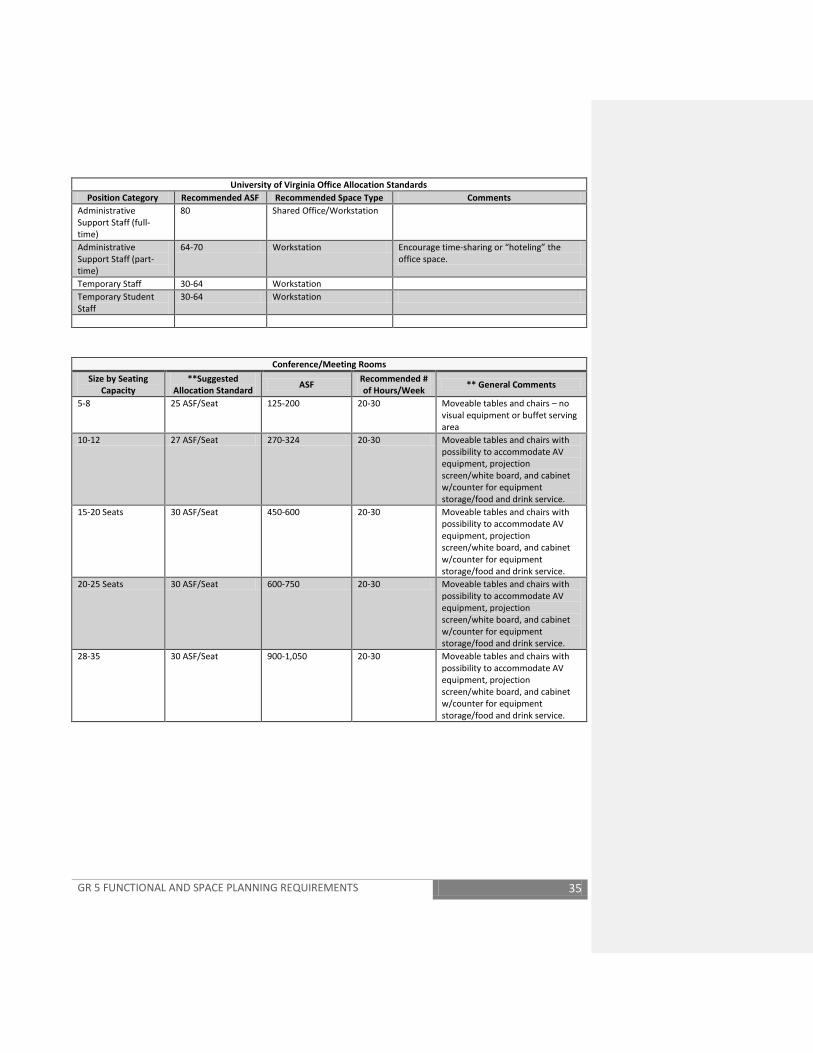
GR 5 FUNCTIONAL AND SPACE PLANNING REQUIREMENTS 35
University of Virginia Office Allocation Standards Position Category Recommended ASF Recommended Space Type Comments
Administrative Support Staff (full-time)
80 Shared Office/Workstation
Administrative Support Staff (part-time)
64-70 Workstation Encourage time-sharing or “hoteling” the office space.
Temporary Staff 30-64 Workstation Temporary Student Staff
30-64 Workstation
Conference/Meeting Rooms
Size by Seating Capacity
**Suggested Allocation Standard ASF Recommended #
of Hours/Week ** General Comments
5-8 25 ASF/Seat 125-200 20-30 Moveable tables and chairs – no visual equipment or buffet serving area
10-12 27 ASF/Seat 270-324 20-30 Moveable tables and chairs with possibility to accommodate AV equipment, projection screen/white board, and cabinet w/counter for equipment storage/food and drink service.
15-20 Seats 30 ASF/Seat 450-600 20-30 Moveable tables and chairs with possibility to accommodate AV equipment, projection screen/white board, and cabinet w/counter for equipment storage/food and drink service.
20-25 Seats 30 ASF/Seat 600-750 20-30 Moveable tables and chairs with possibility to accommodate AV equipment, projection screen/white board, and cabinet w/counter for equipment storage/food and drink service.
28-35 30 ASF/Seat 900-1,050 20-30 Moveable tables and chairs with possibility to accommodate AV equipment, projection screen/white board, and cabinet w/counter for equipment storage/food and drink service.
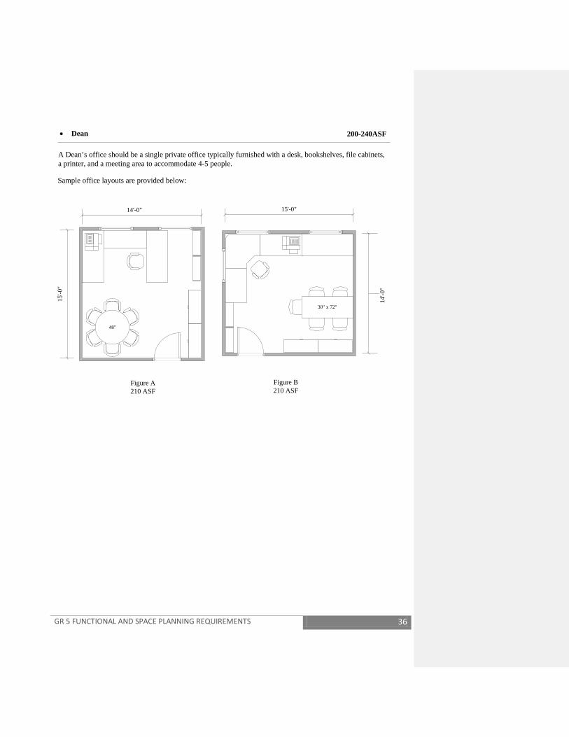
GR 5 FUNCTIONAL AND SPACE PLANNING REQUIREMENTS 36
14'-0"
15'-0
"
48"
Figure A210 ASF
• Dean
A Dean’s office should be a single private office typically furnished with a desk, bookshelves, file cabinets, a printer, and a meeting area to accommodate 4-5 people.
14'-0
"
15'-0"
Figure B210 ASF
30" x 72"
Sample office layouts are provided below:
200-240ASF
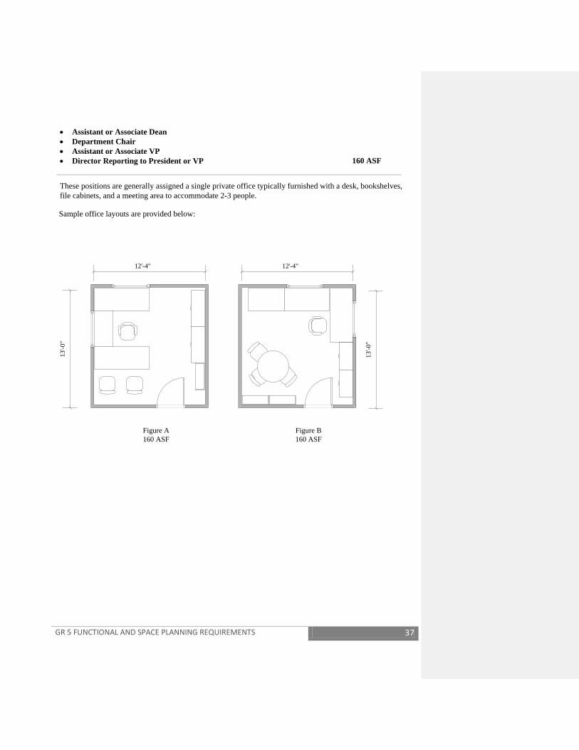
GR 5 FUNCTIONAL AND SPACE PLANNING REQUIREMENTS 37
12'-4"
13'-0
"
Figure A160 ASF
• Assistant or Associate Dean • Department Chair• Assistant or Associate VP• Director Reporting to President or VP
These positions are generally assigned a single private office typically furnished with a desk, bookshelves, file cabinets, and a meeting area to accommodate 2-3 people.
12'-4"
13'-0
"
Figure B160 ASF
Sample office layouts are provided below:
160 ASF
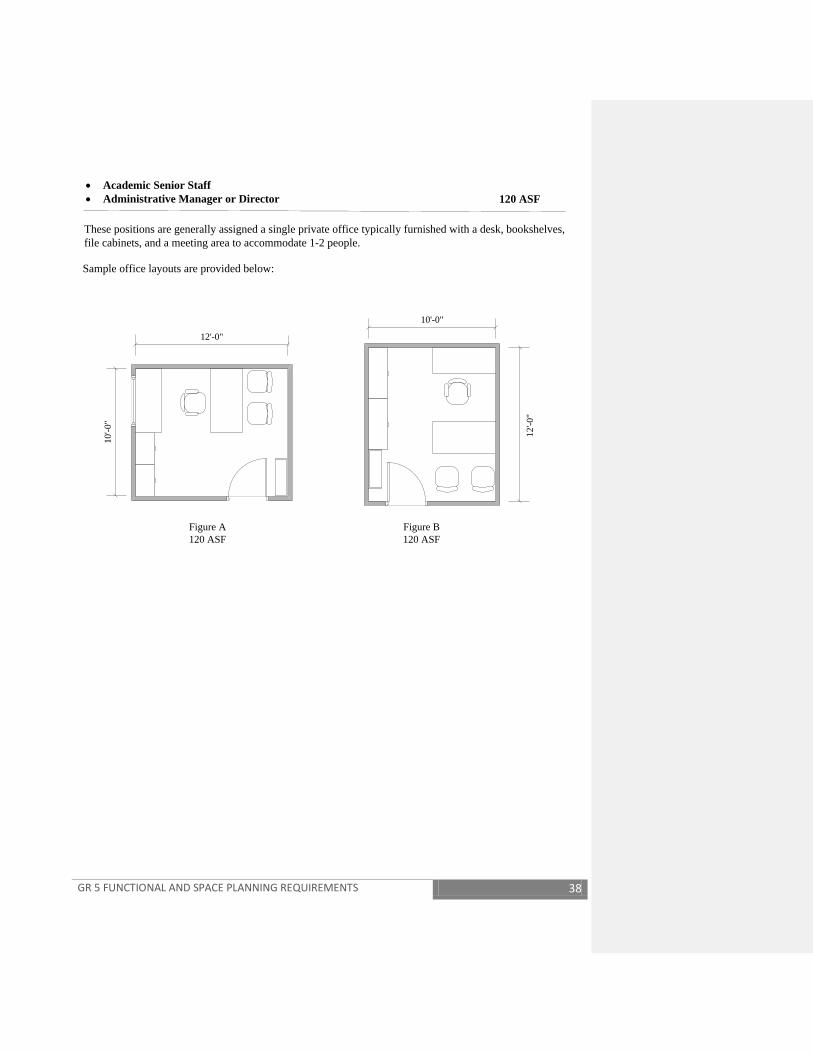
GR 5 FUNCTIONAL AND SPACE PLANNING REQUIREMENTS 38
• Academic Senior Staff • Administrative Manager or Director
These positions are generally assigned a single private office typically furnished with a desk, bookshelves, file cabinets, and a meeting area to accommodate 1-2 people.
Sample office layouts are provided below:
120 ASF
12'-0"
10'-0
"
12'-0
"
10'-0"
Figure A120 ASF
Figure B120 ASF
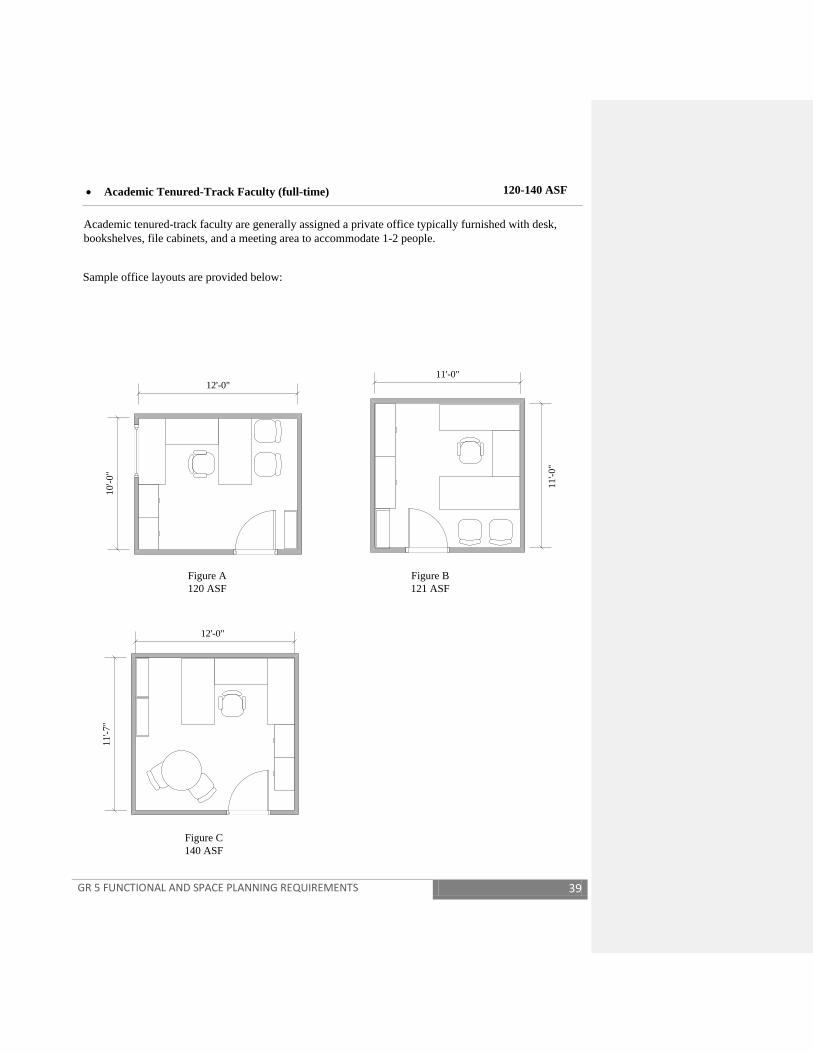
GR 5 FUNCTIONAL AND SPACE PLANNING REQUIREMENTS 39
• Academic Tenured-Track Faculty (full-time)
Academic tenured-track faculty are generally assigned a private office typically furnished with desk, bookshelves, file cabinets, and a meeting area to accommodate 1-2 people.
Sample office layouts are provided below:
120-140 ASF
12'-0"
10'-0
"
11'-0
"
11'-0"
Figure A120 ASF
Figure B121 ASF
Figure C140 ASF
11'-7
"
12'-0"
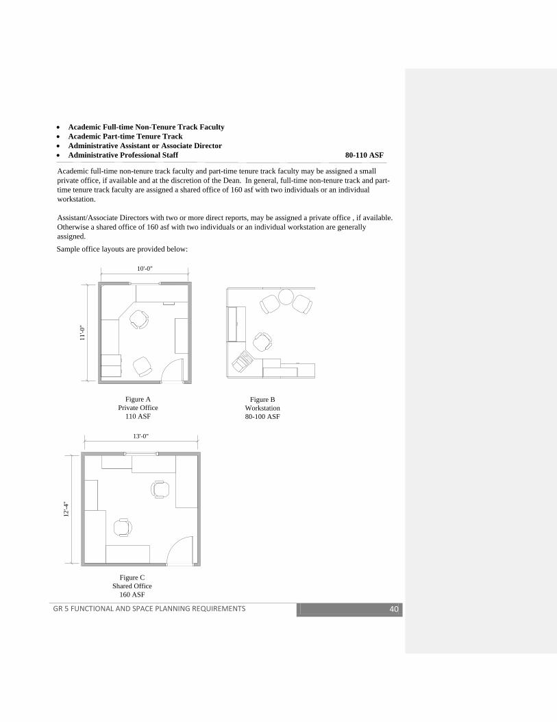
GR 5 FUNCTIONAL AND SPACE PLANNING REQUIREMENTS 40
• Academic Full-time Non-Tenure Track Faculty• Academic Part-time Tenure Track• Administrative Assistant or Associate Director • Administrative Professional Staff
Academic full-time non-tenure track faculty and part-time tenure track faculty may be assigned a small private office, if available and at the discretion of the Dean. In general, full-time non-tenure track and part-time tenure track faculty are assigned a shared office of 160 asf with two individuals or an individual workstation.
Assistant/Associate Directors with two or more direct reports, may be assigned a private office , if available. Otherwise a shared office of 160 asf with two individuals or an individual workstation are generally assigned.Sample office layouts are provided below:
80-110 ASF
10'-0"
11'-0
"
Figure APrivate Office
110 ASF
Figure BWorkstation80-100 ASF
Figure CShared Office
160 ASF
13'-0"
12'-4
"

GR 5 FUNCTIONAL AND SPACE PLANNING REQUIREMENTS 41
• Academic: Part-time non-tenure track faculty • Lecturers• Consulting Faculty• Visiting Faculty• Visiting Scholar • Fellows • Faculty / Research Associate
In general, these positions are assigned a shared office of 160 asf with two individuals or an individual workstation. Another option, as space is available, is to create a community of lecturers, visiting or consulting faculty, etc., in similar disciplines as illustrated in Figure C. In special circumstances, as space is available and at the discretion of the Dean, a small private office may be assigned. For Academic Part-time non-tenure track faculty encourage time-sharing or "hoteling" the office space.
Sample office layouts are provided below:
80 ASF
13'-0"
12'-4
"
30'-6"
17'-0
"
Figure AShared Office
160 ASF
Figure BWorkstation
80 ASF
Figure CWorkstation Center
518 ASF
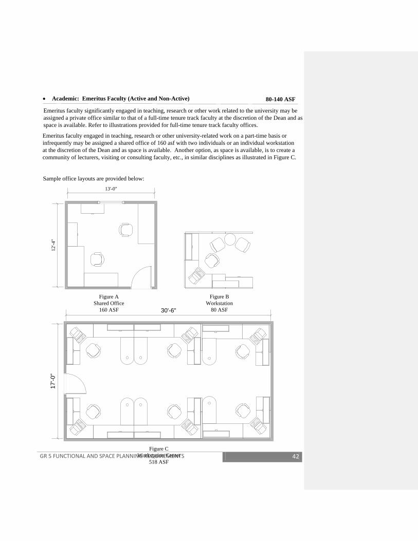
GR 5 FUNCTIONAL AND SPACE PLANNING REQUIREMENTS 42
• Academic: Emeritus Faculty (Active and Non-Active)
Sample office layouts are provided below:
80-140 ASF
Emeritus faculty engaged in teaching, research or other university-related work on a part-time basis or infrequently may be assigned a shared office of 160 asf with two individuals or an individual workstation at the discretion of the Dean and as space is available. Another option, as space is available, is to create a community of lecturers, visiting or consulting faculty, etc., in similar disciplines as illustrated in Figure C.
Emeritus faculty significantly engaged in teaching, research or other work related to the university may be assigned a private office similar to that of a full-time tenure track faculty at the discretion of the Dean and as space is available. Refer to illustrations provided for full-time tenure track faculty offices.
13'-0"
12'-4
"
Figure AShared Office
160 ASF
Figure BWorkstation
80 ASF30'-6"
17'-0
"
Figure CWorkstation Center
518 ASF

GR 5 FUNCTIONAL AND SPACE PLANNING REQUIREMENTS 43
• Adminstrative Support Staff
Administrative support staff are generally assigned a shared office of 160 asf with two individuals or an individual workstation.
Sample office layouts are provided below:
80 ASF
13'-0"
12'-4
"
Figure AShared Office
160 ASF
Figure BThree example workstation
80 ASF

GR 5 FUNCTIONAL AND SPACE PLANNING REQUIREMENTS 44
• Academic Graduate TA / RA • Student Staff • Temporary Staff 30-64 ASF
Academic graduate TAs and RAs who are active students are generally assigned shared office or workstations as space is available.
Sample office layouts are provided below:
Student staff and temporary staff a generally assigned a small workstation.
Figure ASingle Workstation
35 ASF
Figure BSingle Workstation
49 ASF
22'-0"
14'-0
"
Figure CShared Grad TA/RA Office
308 ASF

GR 5 FUNCTIONAL AND SPACE PLANNING REQUIREMENTS 45
• Administrative Part-time Professional• Administrative Part-time Staff 64-70 ASF
Part-time staff are generally assigned a small workstation. Encourage time-sharing or "hoteling" the office space.
Sample office layouts are provided below:
Figure AExample Workstations
64 ASF
Figure BExample Workstations
70 ASF

GR 5 FUNCTIONAL AND SPACE PLANNING REQUIREMENTS 46
Conference / Meeting Room• 8 Seats• 12 Seats
Sample layouts are provided below:
8 Seats @ 25 ASF/Seat198 ASF
18'-0"
11'-0
"
27'-0"
12'-0
"
12 Seats @ 27 ASF/Seat324 ASF
Provided with • Audio/visual equipment, projection screen/marker board• Cabinet w/ counter for housing audio/visual equipment, for storage, and
for food and drink service

GR 5 FUNCTIONAL AND SPACE PLANNING REQUIREMENTS 47
Conference / Meeting Room• 20 Seats
Sample layouts are provided below:
20 Seats @ 30 ASF/Seat600 ASF
32'-0"
18'-9
"
Provided with • Audio/visual equipment, projection screen/marker board• Cabinet w/ counter for housing audio/visual equipment, for storage, and
for food and drink service
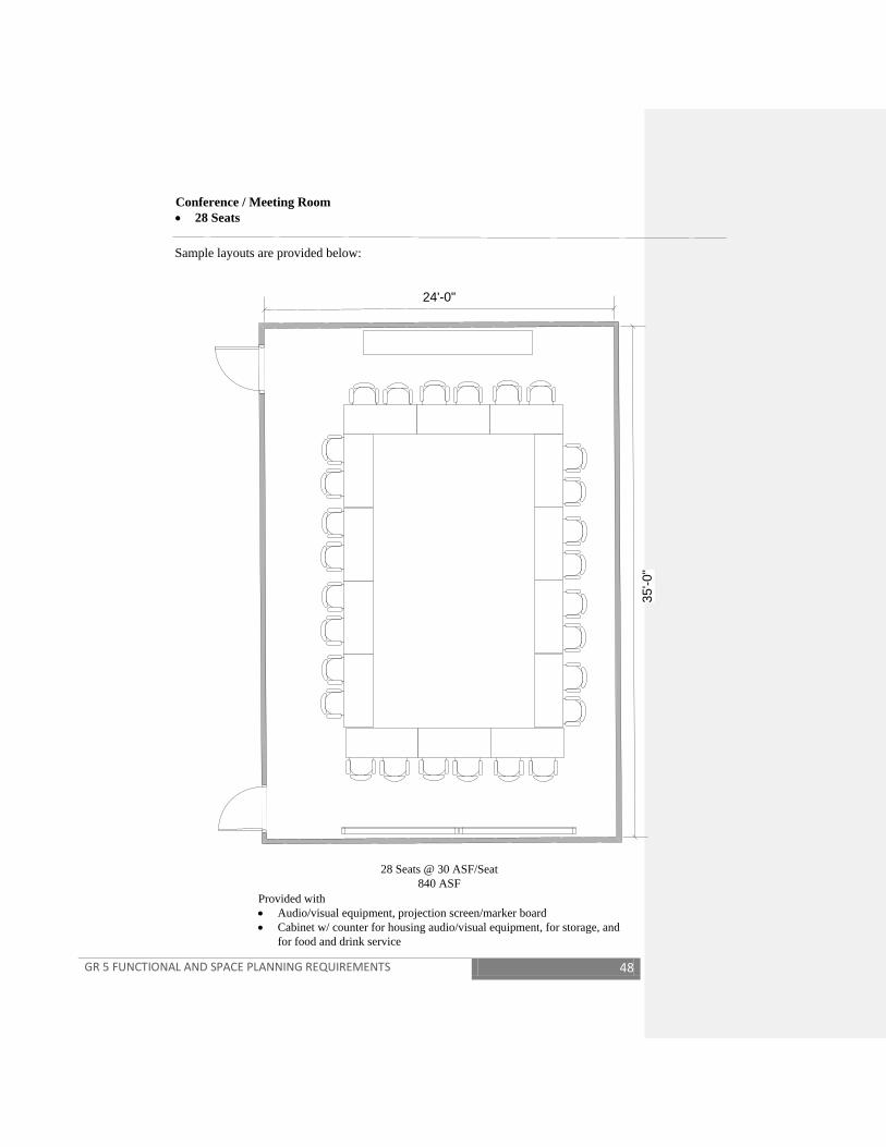
GR 5 FUNCTIONAL AND SPACE PLANNING REQUIREMENTS 48
Conference / Meeting Room• 28 Seats
Sample layouts are provided below:
28 Seats @ 30 ASF/Seat840 ASF
24'-0"
35'-0
"
Provided with • Audio/visual equipment, projection screen/marker board• Cabinet w/ counter for housing audio/visual equipment, for storage, and
for food and drink service
GR 5 FUNCTIONAL AND SPACE PLANNING REQUIREMENTS 49
Classroom standards vary depending on the type of classroom and the facility. The Office of Space and Real Estate Management establishes the standards applicable for classroom programming and furnishings. Space requirements, based upon these guidelines, shall be reflected in the programming of projects and the Schematic Design. The space requirements so established shall be adhered to throughout the design process. The A/E may not make assumptions or exceptions to the above based upon other standards or their standard practice.
GR 5.2 SPECIAL BUILDING PLANNING REQUIREMENTS GR 5.2.1 BUILDING EFFICIENCY RATIOS
A building efficiency of sixty-five to seventy-five percent (65% to 75%) shall be achieved for classroom, dormitory (with shared toilets), office, laboratory, assembly, and dining facilities, or combinations of these uses unless predetermined otherwise in University programming. Higher efficiencies per standard industry criteria would apply to service buildings, warehouses, garages, and other housing or dormitory (suite with internal toilets), apartments or townhouses.
GR 5.2.2 MINIMUM DESIGN LOADINGS FOR BUILDINGS
The minimum design loadings indicated in the current VUSBC shall be modified and/or supplemented as hereinafter indicated for the design of University buildings.
The minimum design roof live load or snow load for flat roofs and roofs with a slope of less than four (4) inches per foot shall be as indicated on Figure 7, Minimum Superimposed Loads for Design of Low-Sloped Roofs and Figure 7A, Ground Snow Loads, which supplements the VUSBC requirements for designing University buildings. Areas west of the Blue Ridge Mountains shall have a minimum design roof live load of 30 pounds per square foot. Areas east of the Blue Ridge Mountains shall have a minimum design roof live load of 20 pounds per square foot. Ground snow loads west of the Blue Ridge Mountains are determined by case studies and other VUSBC requirements.
GR 5.2.3 ROOM NUMBER ASSIGNMENT PROCEDURE All accessible enclosed spaces must have SCHEV room numbers assigned by the Office of Space and Real Estate Management or, in the Health System, by the Office of the Associate Vice President for Health System Planning and Facilities. The A/E, through the Project Manager, shall provide an appropriate number of half-size copies of floor plans not later than at the Preliminary Design (50%) submission for the assignment of SCHEV room numbers by the appropriate Space Administrator. Additional submittals are required if plans have changed since Preliminary Design submission. If
GR 5 FUNCTIONAL AND SPACE PLANNING REQUIREMENTS 50
CADD files are submitted they shall be in CADD format. The purpose of assigned room numbers is to facilitate service work orders and building record documentation. The assigned room numbers provided to the Project Manager shall be incorporated in the construction document (95%) submission. The A/E shall be responsible for obtaining the assigned numbers from the Project Manager. Door numbering shall relate to assigned room numbers in a logical sequence, such as single doors being the same as room number, such as 1001, 1001A or J1001 where assigned room numbers have a suffix or prefix. Multiple doors into one space shall be 1001A, 1001B, etc. or 1001A-1, 1001A-2, etc. as logically applicable. During the bid phase the A/E shall provide the Project Manager with plans in CADD format for transmission to the appropriate Space Administrator (Academic or Health Systems) with all non-relevant layers turned off. Relevant layers show walls, windows, doors, interior ramps, stairs, elevators, shafts, bathrooms, partitions (e.g. low/half walls, retractable wall system, and modular partitioning), roof, assigned SCHEV room numbering, room descriptive (e.g. office, classroom, conference, men’s toilet, mechanical room, etc.), and occupancy notation (e.g. occupancy load or number of stations). Where room and door numbering signage is provided by the contractor it shall be installed prior to final inspection for occupancy or substantial completion.
GR 5.2.4 LIFE, RESEARCH AND FACILITIES FIRE PROTECTION
Established University policy requires that all new construction will include fire detection and suppression systems. Projects within existing facilities will be expected to include fire detection and/or protection as part of the project up to a minimum of 10% of the renovation project construction cost.
GR 5.2.5 LACTATION ROOM DESIGN
The Patient Protection and Affordable Care Act (“PPACA”) was signed into law on March 23, 2010. This law amended Section 7 of the Fair Labor Standards Act (FLSA). Under this Act, employers are required to provide an area, other than a bathroom, that is private and free from intrusion from coworkers and the public, which may be used by an employee to express (pump) breast milk for their child. The space can be temporarily assigned or converted for the duration of a mother’s need. A/E shall incorporate the guidelines below when planning lactation rooms for new buildings or major renovations and departments should reference this information when retrofitting existing spaces to serve this purpose. (1) Size: Fifty square feet to accommodate the recommended furniture and
equipment. (2) Location: Lactation rooms should be located in a safe, accessible area.

GR 5 FUNCTIONAL AND SPACE PLANNING REQUIREMENTS 51
(3) Privacy: Install a user-operated, indicator dead bolt that displays an “occupied” message to discourage interruptions.
(4) Sound Privacy: Walls shall be constructed to the structure above to minimize sound transmission; sound attenuation shall be installed, installation of fabric panels on the walls is encouraged.
(5) Furniture: Provide a table to be used as a work surface for the pump and bottles to rest on in front of the task chair. Provide a comfortable, adjustable task chair with arms.
(6) Electrical: Provide an electrical outlet to power breast pump and refrigerator. (7) Plumbing: Provide a sink and faucet combination deep enough to wash bottles
and pump parts. Goose neck or kitchen type faucets shall be specified. (8) Lighting: Task lighting shall be specified over work area (9) HVAC: Temperature should be maintained year-round at a comfortably warm
level such as a dressing room. Locate individual thermostat in room for user control and thermal comfort.
(10) Equipment: Install a compact refrigerator for milk storage. (11) Accessories: Provide trash can, paper towel dispenser, coat hook, mirror, hand
sanitizer GR 5.2.6 CONFINED SPACE REQUIREMENTS
All structures shall be designed in an effort to minimize the number of confined spaces. When the creation of a permit required confined space is unavoidable, one or more of the following actions shall be taken to reduce the hazards associated with the space: • Install a remote monitoring and inspection system and automated cleaning system to eliminate or minimize the need for entry into a confined space; • Provide mechanical ventilation (mechanical ventilation in confined spaces avoids build-up of contaminants or combustible atmospheres); • Design adequate means of entry and exit (provisions should be made for the entry and exit for persons who may be required to wear personal protective equipment, a breathing apparatus, and protective clothing); • Design suitable illumination on emergency power, not timer switches (lighting shall be sufficient for safe entry, conducting work, and exiting); and, • Eliminate fall hazards (provide fixed ladders, guardrails, platforms, and anchor points for personal fall arrest systems) and provide non-slip work surfaces (e.g., textured flooring).
GR 5.2.7 FALL HAZARDS
Structures shall be designed to eliminate fall hazards during routine and non-routine use, maintenance, repairs, and all other purposes. Where exposures to fall hazards are unavoidable, the hazards involved in working at heights above 6 feet should be minimized by incorporating the following into building design:
• • Anchorages to which personal fall arrest equipment is attached shall be capable of
supporting at least 5,000 pounds (22.2 kN) per employee attached as required by the Occupational Health and Safety Administration.
GR 5 FUNCTIONAL AND SPACE PLANNING REQUIREMENTS 52
• Install guardrails and toe boards where people are exposed to falls of six feet or greater. Standard railings with standard toe boards shall be installed on all exposed sides except at the entrance to the opening. The railings and toe boards shall be constructed in accordance with the ANSI standard A1264.1-1995).
GR 5.2.8 HAZARDOUS WASTE STORAGE
• The following considerations should be made when designing a hazardous waste
shipping, receiving and/or storage area: • The hazardous waste storage area should be located in a room or area away from public
access and equipped with appropriate security to minimize public access. Doors to the area must be properly fire-rated and equipped with locks to prevent unauthorized entry.
• Size of the storage area should include considerations of the number of laboratories, type and amount of waste each laboratory generates.
• Area must be set-up to ensure that waste containers can be adequately segregated and contained. In addition, there must be enough space to ensure at least 3 feet of aisle space between shelving and/or waste containers.
• Area must be equipped with a dedicated ventilation exhaust system designed to adequately control volatile emissions in area.
• The floor must be sealed (typically an epoxy-resin to eliminate all cracks and gaps and a berm installed at doorways or other locations where spilled material could escape the room). The containment system (floor) must be able to hold at any time 10% of the total volume of liquid hazardous waste in the area or 110% of the largest container, whichever is greater.
• Area shall be equipped with the following equipment: • Fire Suppression System and fire extinguishers - appropriate for the fire hazard
presented by the waste stored in the area, • Intrinsically-safe lighting, • Emergency shower and eyewash, • Spill kit must be located in area and there must be access to emergency shower and eye
wash, • Exit Signs - posted at all exit ways from the area.
GR 5.3 SECURITY GR 5.3.1 DESIGN FOR CRIME PREVENTION
Site and building design shall include consideration of the “Design Checklist for Crime Prevention” found below in conjunction with participation by a designated representative of the University Police Department and Office of Emergency Preparedness.
GR 5 FUNCTIONAL AND SPACE PLANNING REQUIREMENTS 53
Mandatory Requirements: The following Facilities Design Guidelines considerations shall be applied to site and building design, unless written exemption is given by the CFO.
SITEWORK, SW 3.2 Site Lighting SITEWORK, SW 3.8 Emergency Telephones INTERIORS, INT 2.2.2 Locksets INTERIORS, INT 2.2.7 Health System Door Locking Hardware
These requirements have been jointly created by Facilities Management and senior University administration in response to concerns for the safety and welfare of students, faculty, staff, and the public on University properties, and related recent events. The design process shall evaluate the following Design Checklist for Crime Prevention: (1) What can be done to improve building security at little or no cost? (2) Does the design make it difficult for people to accidentally or purposely harm
the building, its occupants, and contents? (3) Are vehicle barriers needed to keep vehicles from having easy access to areas
not intended for service vehicles? (4) Is lighting adequate? (5) Are emergency telephones appropriate on the site? (See GENERAL
REQUIREMENTS GR 5.4.5 Emergency Telephones) (6) Is unauthorized access to a roof from the ground prevented? (7) Does landscaping contribute to security? (8) Have Crime Prevention through Environmental Design (CPTED) concepts (See
Appendix E) appropriate to the project been applied?
Parking under a building is not permitted, and parking near a building is subject to scrutiny.
GR 5.3.2 OFFICE OF EMERGENCY PREPAREDNESS
The Office of Emergency Preparedness shall be afforded the opportunity to review projects for campus safety and security and for card access and security camera locations. The Office of Emergency preparedness will coordinate review by the Department of Police and the General Safety and Security Committee into a single review process. The Project Manager should schedule this review around the completion of Schematic Design. Particular concerns include landscaping, building entrances, walkways and parking areas, which shall be adequately lighted and free of areas hidden from view that could encourage criminal activity. Line of sight and accessibility for police personnel shall be given design consideration, including proposed or future surveillance cameras.
GR 5.3.3 BUILDINGS AND STRUCTURES

GR 5 FUNCTIONAL AND SPACE PLANNING REQUIREMENTS 54
In addition to the above, buildings and structures shall discourage unplanned access to other buildings through basements, underground utility structures, attics, corridors that do not lend themselves to security surveillance, or across roofs.
Underground utility structures (tunnels) required to have fire and emergency ingress or egress shall be alarmed to send signals to the police, or a manned security post, and to FM Systems Control Center as well as to audible devices at the point of entry and elsewhere within the building or on the building exterior. These alarmed points of entry shall be keyed so that authorized personnel can interrupt and reactivate the alarm circuit when the opening is closed.
Providing a secure environment is important to the University. The University seeks to prevent crime using concepts commonly known as Crime Prevention through Environmental Design (CPTED). These concepts include the allowance for natural surveillance, natural access control, and development of territoriality. In addition, many outside references are available to the designer to assist in developing designs that address the many issues related to security and crime prevention in and around University buildings and grounds. A list of available resources and general guidelines are provided in Appendix E. The following are specific security requirements applicable to new construction, site modifications, renovations affecting building entrances or exits, or security system modifications or replacements at the University.
GR 5 FUNCTIONAL AND SPACE PLANNING REQUIREMENTS 55
GR 5.3.4 SECURITY SYSTEMS
All new buildings, renovation projects exceeding $5,000,000 in project cost, or existing buildings with a building code change of use, shall include a security access (card reader) system for all exterior doors and such interior doors as determined by the Building Committee. Any exemptions on a case by case basis shall be determined by an approved Determinations and Findings Report after first consideration by the Building Committee. The security access system shall be installed and operational prior to the issuance of a Certificate of Use and Occupancy. The A/E shall determine, in consultation with the Project Manager, the security systems requirements for each project. The A/E, through the Project Manager, shall determine the design and operational compatibility of the security access system in consultation with the Office of the Vice President for Business Operations for Academic buildings, (card system), and ID Services for Health System buildings. Building design and construction shall provide conduit, outlet boxes, power source(s), backboards, and adequate spatial requirements to accommodate and support the installation of a University compatible card reader security access system. The card reader security access system shall be determined on a project by project basis as to whether it is installed by the building contractor or by a separate contractor coordinated for completion as required for issuing a Certificate of Use and Occupancy. See GR 5.3.7 Electronic Access Controls.
GR 5.3.5 SURVEILLANCE CAMERA SYSTEMS
For all new buildings, renovation projects exceeding $5,000,000 in project cost, or existing buildings with a building code change of use, the Office of Emergency Preparedness security review shall consider applicability of exterior surveillance cameras to overall campus safety and security. The Committee’s review will also consider the applicability of interior security cameras in consultation with the Building Committee. When exterior surveillance cameras are requested, the project shall provide infrastructure as follows: (1) Conduit from selected exterior locations to accessible points inside the building (2) Power accessible to selected camera locations (3) Backboards at selected utility room locations, with power, data connection, and
adequate spatial requirements to accommodate and support the installation of a University compatible security camera system.
Any exemptions on a case by case basis shall be determined by an approved Determinations and Findings Report after first consideration by the Building Committee. The required exterior security camera infrastructure shall be installed and operational prior to the issuance of a Certificate of Use and Occupancy.

GR 5 FUNCTIONAL AND SPACE PLANNING REQUIREMENTS 56
Requirements for exterior security camera infrastructure shall not include cameras, cabling, control equipment, or connection to the university data network. The University Architect’s Office shall advise on the appearance and location of exterior surveillance cameras, consistent with achieving intended functionality. A Building Committee may elect to include functioning interior and/or exterior surveillance camera systems in any project. The Office of Emergency Preparedness and Department of Police will assist and advise the Project Committee and, through the Project Manager, the Architect/Engineer, in this effort. When surveillance camera systems are provided, they shall be operationally compatible with the University system. The Department of Police will generally provide monitoring of security camera systems, but this service may require projects to provide additional monitoring capacity at the Department’s central monitoring facility.
GR 5.3.6 ON ALERT ELECTRONIC MESSAGE BOARDS
All new or renovated classrooms or places of assembly with 75 or more persons shall provide a University furnished, contractor installed emergency notification system and Ethernet connection. Major renovations (10,000 square feet or $1,000,000 construction) shall incorporate security access systems. Smaller renovations will be determined on a case by case basis. Consultation during design with the University of Virginia Police Department and/or Hospital Security, as appropriate, shall seek to assure the adequacy of the proposed design including incorporation of CPTED concepts in Appendix E. Power for security systems and devices is to be from an emergency circuit where available.
GR 5.3.7 ELECTRONIC ACCESS CONTROLS
Electronic access control provides the University community after-hours access to facilities via the University ID card, minimizes the ability of unauthorized individuals to enter facilities through unsecured doors, and reduces the need to issue hard keys. Exterior doors in new construction and major renovations (plus select interior doors as requested by building occupants) shall be equipped with electronic access controls connected to the University’s one card system. Through standing contract with the CBORD Group, Inc., the University provides electronic access control using CBORD’s Squadron access control panels. Squadron panels communicate with the University’s CBORD CSGold servers over the University network, granting real-time access based on privileges assigned through the one card system.
GR 5 FUNCTIONAL AND SPACE PLANNING REQUIREMENTS 57
Effective design and implementation of any electronic access control system requires an understanding of the intended use and typical daily operation of the facility. In order to be effective, the entire building perimeter must be addressed to determine the most cost effective combination and layering of access control, including:
(1) Primary entrance (during & after hours use) – typically equipped with card
reader to allow after hours entrance, door is electronically locked & unlocked by predetermined schedule. Free egress at all times. Components include: o card reader o electronic locking hardware o door position switch o request-to-exit detector o local alarm sounder
(2) Secondary entrance (accessible during normal business hours only) – no after-hours access, door is electronically locked & unlocked by predetermined schedule. Free egress at all times. Components include: o electronic locking hardware o door position switch o request-to-exit detector o local alarm sounder
(3) “Exit only” door – mechanically locked at all times, may be configured for free egress or local alarm activation upon door opening (emergency exit only). Components include: o door position switch o local alarm sounder o request-to-exit detector (not installed for emergency exit only)
When determining whether card reader, electronic locking/unlocking, or monitoring should be specified, it is important to evaluate occupancy and use patterns for the facility. Where possible, points of highest traffic shall be equipped with electronic hardware for daily locking/unlocking. Card readers shall be installed on well-lit, easily identifiable and visible entrances. Monitoring and local audible (“prop”) alarms shall be configured for all entrances to discourage propping of doors after hours. Keys shall not be issued to these doors, eliminating problems and costs associated with lost/misplaced/stolen keys and associated rekeying expenses. Lost cards can be immediately deactivated and new credentials issued without impacting other facility users.
Selection of electronic door hardware will vary depending on many factors, including facility design and construction, architectural style, life safety and building code issues. A/E shall follow the general guidelines below when specifying electronic door hardware:
(1) Function shall be fail secure
(a) Hardware provides free mechanical egress (b) No connection required to building fire alarm system
o Note: certain life safety or fire code provisions may dictate the use of fail-safe hardware and interconnection with the building fire alarm
GR 5 FUNCTIONAL AND SPACE PLANNING REQUIREMENTS 58
system for specific doors. These exceptions must be coordinated with the Project Manager and reviewed by the University’s access control specialist.
(2) Electric locks, electric strikes and electric trim may be either 12Vdc or 24Vdc o Note: the University will provide filtered & regulated 12Vdc or 24Vdc to
power electric strikes, locks, and trim. Separate power supplies shall not be provided with the hardware.
(3) Electric latch retraction devices: (a) typically require a manufacturer-specific power supply
o High in-rush current dictates conductor size and maximum cable length to power supply • Max cable length may dictate installation of power supply near door • Where possible, mount power supply in access control closet
(b) Power supply requires 120V AC cord & plug connection (c) Specify hardware which includes battery backup integral to power supply
(4) ADA doors with power operators shall be equipped with electric strike or electric latch retraction device and be interconnected with the electronic access controls.
(5) If pulls are desired on both leaves of double doors, both leaves shall receive electronic hardware (i.e. both doors unlock/unlatch on card swipe). (a) If electric hardware is not desired on both leaves, the inactive leaf shall not
be equipped with an exterior pull. (b) Double doors with a single active leaf and one inactive leaf must be
configured to ensure positive latching of the inactive leaf whenever the active leaf is closed and latched. Preferred solution is to equip inactive leaf with automatic flush bolt(s) and door coordinator.
(6) Magnetic locks are discouraged due to increased life safety concerns (connection to fire system, local physical bypass switch, etc.).
In addition to standard electronic hardware which can be activated/controlled via relay contact closure or application of power, the following specialty products are integrated with and fully configurable through CSGold: (1) Schlage AD-300 networked wired locks (2) Schlage AD-400 networked wireless locks (Schlage AD-400 is currently the only
wireless lock approved for use with CSGold)
These specialty hardware options require far less door & frame prep than standard hardwired installations, and can in some instances significantly reduce installation costs. A/E shall provide Infrastructure for access control projects to include the following:
(1) A dedicated location for installation of access controls
(a) Preference is for a dedicated room/closet with: o locking door with electronic hardware and card reader o minimum 32 sf available wall surface area o controlled temperature and humidity o minimum 2 each dedicated 120V 20 amp quad receptacle on emergency
circuit with generator backup (if available). Facilities with large numbers

GR 5 FUNCTIONAL AND SPACE PLANNING REQUIREMENTS 59
of controlled doors or extensive use of latch retraction devices may require additional circuits or outlets.
o network (data) drop o open paths/sleeves to pull cable from controls to door locations
(b) Accommodation can be made for a less secure space, as long as access to the space is restricted (i.e. no general public) and meets the other requirements noted above.
(2) Open cable paths (conduit, flex) from accessible ceiling to points of termination
within the door and door frame. Sample sketches are included in a separate document, “ACCESS CONTROL-DETAILS-REV2.pdf”. These are representative sketches intended to convey preferred routes for cable and typical installation details for various components and local conditions. In addition to these line drawings, the following points shall be verified during design & construction: (a) AC power shall not be run in the same conduit or junction box as low
voltage access control cable. (b) Junction boxes shown in the sample sketches may omitted if the following
conditions are met: o obtain prior written approval by the Project Manager and University
access control specialist o individual conduits can be stubbed above doors in a concealed but
accessible ceiling. o conduits are grouped in one location (no more than 12” between
outermost conduits) to allow for splitting of the composite access control cable bundle and routing of the individual component cables to their points of termination within door & frame.
(c) Conduit routed to door frame shall have the minimum number of wide radius bends required to reach the desired location. In no instance shall bends exceed 180 degrees without an intermediate (and accessible) junction box or pull “L”. o Minimum conduit size to accommodate composite cable is 1” o Minimum conduit size to accommodate up to three individual cables
separated from the composite cable is ¾” o Minimum conduit size to accommodate one or two cables separated
from the composite cable is ½” (d) Pull strings shall be installed from junction box (or stub-out above ceiling) to
point of termination in all conduits. (e) Grouted frames shall be equipped with mortar boxes around electric hinges,
electric power transfers, electric strikes, door contacts, etc. (f) Use factory installed raceway within hollow metal frames (g) Where ADA operators are installed:
o A minimum of one ADA push button must be hardwired to the ADA operator.
o Card reader shall be installed adjacent to ADA pushbutton, and may share a common conduit run.
The University’s Office of Business Operations procures and installs the following components and services with respect to access control projects:

GR 5 FUNCTIONAL AND SPACE PLANNING REQUIREMENTS 60
(1) Squadron access control modules (2) Enclosure for Squadron controls (where required) (3) Card readers (4) Alarm horns/sounders (5) Request-to-exit devices (motion detectors) (6) Door position switches (door contacts), normally open (7) Modular DC power supplies serving:
(a) Squadron controls (b) Request-to-exit devices (motion detectors) (c) Alarm horns/sounders (d) Electric strikes/locks (e) Note: power supplies for latch retraction hardware shall be provided by
hardware supplier (8) Cable (9) Installation services through University term contracts to include mounting and
connecting: (a) Squadron panels (b) University provided power supplies (c) Card readers (d) Door contacts (e) Request-to-exit devices (f) Termination of cabling to electrified hardware provided by general
contractor
Note that, if desired, door contacts may be prepped and provided under the construction contract.
GR 5.3.8 SECURITY AND SOURCES OF NOXIOUS OR TOXIC FUMES
Each building, whether new or renovated, needs to be considered for security needs and the prevention of noxious or toxic fumes from entering occupied spaces. Some buildings will have more stringent needs, such as those where large numbers of persons gather or a medical research building. All buildings including major renovations and upgrading of heating, ventilation, and air conditioning systems require a number of features that are to be incorporated: (1) Site and building design shall include consideration of outside air intakes for
heating, ventilation and air conditioning related to sources of noxious or toxic fumes. Project Manager and A/E shall be responsible for actions wherein existing conditions and/or prevailing winds are not clearly understood.
(2) Outside air intakes shall be sufficiently above exterior grade (30’-0” or at third story
level) and remote from loading docks, emergency or ambulance vehicle entrances, etc., on all new buildings and major renovations to avoid intake of noxious or toxic fumes associated with vehicles, maintenance equipment, electrical generators, similar sources of fumes permanently or intermittently associated with building functions and maintenance, and to discourage malicious contamination.

GR 5 FUNCTIONAL AND SPACE PLANNING REQUIREMENTS 61
Consideration also shall include proximity to wind-blown dust from streets, fields and ground care activities, designated tobacco smoking areas, combustion by-products, and biogenic materials related to evaporative cooling towers or intentional human contamination.
(3) Dedicated mail rooms shall be exhausted and shall be under negative pressure.
GR 5.4 Not Used. GR 5.3.8 EMERGENCY TELEPHONES
New buildings, new parking lots and major site work projects shall provide the location(s) for emergency telephone(s) that are handicapped accessible, hands free operated, and located on or near lighted walkways providing visibility and comfort in their use. Project Manager shall determine approved locations and type(s) of installation in consultation with the University Safety and Security Committee. Two types of emergency telephone styles are applicable. In all installations the telephone shall be University provided and installed on or in the assembly. The type applicable to most locations is a Facilities Management fabricated and installed assembly as illustrated in Figure 8. Specifications shall state the requirements of the contractor. In some cases Facilities Management will be fully responsible for installation including necessary wiring and telephone cabling to a University point of connection. Facilities Management Department of Utilities will procure and install the Figure 8 fabricated assembly including the telephone and light fixture. For areas determined by the University Safety and Security Committee and large parking lots (more than 49 cars), the use of pre-manufactured emergency telephone assembly is appropriate. For each additional 99 parking spaces, an additional emergency telephone is required. Where approved by the University Landscape Architect this “tower” type assembly may be taller than 8-feet for large parking lots for visibility over vans and similar taller vehicles. Where the “tower” type emergency telephone is applicable, the design shall be similar to Gai-tronics Corporation Model 234 Stanchion and/or model ETP-MT/R by Talk-A-Phone Co., and shall be ADA compliant. Color(s) shall be approved by the University Landscape Architect. Power for emergency telephones is to be an emergency circuit where available.
GR 5.5 BUILDING SYSTEMS ACCESS AND EQUIPMENT
Rooftop mounted equipment (excluding fume hood exhausts, power roof ventilators, and similar equipment functionally required on rooftops) is discouraged. Adequate

GR 5 FUNCTIONAL AND SPACE PLANNING REQUIREMENTS 62
space for building systems equipment shall be provided in programming and Schematic Design. Rooftop equipment in new construction is subject to CFO approval. Rooftop equipment where permitted shall be screened from view of other buildings, streets and walkways. Where rooftop mounted equipment is approved or necessary there shall be considerations for access carrying maintenance tools and equipment, replacement of the equipment, and lighting for night maintenance or repair. Roofs with mechanical or electrical equipment shall have access by an enclosed stairway except in renovations where impractical. Ladders and a hatchway may be used for access to roofs without rooftop equipment. Safe access to all roof levels shall be provided for practical roof and equipment maintenance. Elevated rooftop equipment shall have permanently installed ladders and platforms to provide access to all access doors and items that require maintenance. Rooftop mechanical and electrical equipment shall be accessible by durable walkways to protect the roofing during required maintenance or repair. Service walkways shall not be less than two feet wide and shall extend six feet from the equipment on sides requiring service or repair accessibility. See BUILDING ENVELOPE BE 5.1 Rooftop Equipment. Building systems (mechanical, electrical, telephone/data communications) space shall include considerations for routine and emergency maintenance access and adequate space for storage and/or use of related drawings, specifications, and operations and maintenance manuals.
GR 5.6 INFORMATION TECHNOLOGY & COMMUNICATIONS (ITC) Programming and Schematic Design shall meet requirements established through the Project Manager by Information Technology and Communications. ITC equipment rooms shall be dedicated for information technology and telecommunications use (telephone, data and entertainment video services). These rooms shall not be used to support any other building utility. Consultation with ITC shall be considered in the determination of room size requirements related to the projected number of outlets served including not less than thirty-three percent growth (growth percentage may be higher if programmatic needs are not clear). The following information is summarized from ITC website http://itc.virginia.edu/csd/net/buildingtelecom/, which may prove useful to the Project Manager and A/E. Waivers of the following requirements require ITC approval except those specifically established by these Facility Design Guidelines that exceed or clarify ITC requirements.
GR 5 FUNCTIONAL AND SPACE PLANNING REQUIREMENTS 63
Telecommunications room/closets shall have: (1) A minimum size of 6’-0” x 8’-0 (serves up to 100 outlets) (2) 9’-0” minimum height (3) No suspended or false ceiling unless required by building code construction
requirements (4) A lockable 3’-0” minimum width, 6’-8” minimum height door opening out unless
prohibited by building code requirements for fire exit access passage width. (Room size may need to be increased if the door must swing into the room.)
(5) 50 foot-candles illumination level at 3’-0” above floor, ceiling mounted 8’-6” minimum clear above floor (no wall mounted light fixtures)
(6) HVAC capacity to maintain ambient room temperature below 75 degrees (typical heat load less than 6,000 watts), 30-75% relative humidity, and a slight positive pressure. HVAC capacity to be available 24/7 year-round.
(7) Fire-treated ¾” plywood from floor to 8’-0” above finish floor on three walls. Telecommunications rooms/closets shall: (1) Be stacked vertically where possible and be interconnected by 4-4” bushed
sleeve floor penetrations extending 1” above the floor (2) Be interconnected horizontally at minimum of every three floors with a cable
tray above suspended ceiling or conduit where ceiling is not accessible, with a run distance not exceeding 90 meters.
(3) Be within 90 meters of cable run distance of the most remote site (multiple closets required where this distance cannot be achieved with one closet)
Cable tray, when provided, shall be a minimum of 12” x 4”deep. See ITC guidelines for acceptable cable tray type. See BUILDING SERVICES BSRV 6.3.1 Telecommunications, for additional technical requirements, such as electrical power outlets, building entrance termination, grounding, cable tray, conduit, and outlets.
GR 5.7 CUSTODIAL ROOMS Provide one custodial room for each 15,000 to 18,000 gross square feet, with a minimum of one room per floor. Two custodial rooms are required on floors greater than 18,000 gross square feet. Provide a central custodial room in each building on a level accessible from a service or loading dock entrance, containing a minimum area of 130 square feet to accommodate the following: (1) Open storage space for one wheeled cart and one floor machine (2) 18 linear feet of shelving 24 inches deep with 14 inches vertical separation (3) 3' x 3' floor service pan/sink with drain and three mop holders, with
impermeable surface two feet minimum above the sink on any adjacent wall (4) Broom hanger strip or hangers to accommodate a minimum of three brooms (5) Space to accommodate two (2) stepladders (6) Space for small desk with data/telephone outlet (see exception)

GR 5 FUNCTIONAL AND SPACE PLANNING REQUIREMENTS 64
(7) Two (2) GFCI type duplex electrical outlets centered 18 inches above the floor in accessible locations (one adjacent to corridor door)
(8) Motion detector switch for overhead lighting fixture (9) Water resistant flooring with a floor drain with a 1/4-inch per foot floor slope to
the drain throughout the room (10) Exception: When agreed by housekeeping minimum area can be 100 square feet Locate closets adjacent to restrooms and elevators. Trailers and other custodial rooms shall accommodate 20 square feet of open floor space, 8 linear feet of shelving 24" deep with 18 inches vertical separation (not exceeding 7'-2" above the floor to the top shelf). See BUILDING SERVICES BSRV 1.9 Custodial Rooms and BSRV 4.4.6 Distribution, General Exhaust.
GR 5.8 UVA RECYLING SPACE GUIDELINES
Each floor of new construction or significant renovation projects shall provide for paper recycling in moveable storage (provided by the University) and for aluminum can recycling located for the convenience of the occupants. Additionally, the Project Manager will coordinate with The Division of Recoverable and Disposable Resources (DRDR), also known as UVA Recycling, to provide such additional space requirements as determined suitable for the tenants and/or functions of the project for plastics, glass, cardboard or other materials. For programming space and design, space allotment shall provide for the following: (1) 60 to 80 square foot supply room near or adjoining new loading docks (to be
equipped by others) with motion detector light switching (2) minimum of one (1) floor space 16 inches by 52 inches to accommodate
stationary paper storage shelving and potential built-in units in each departmental or functional area defined by access and usability for occupants
(3) minimum of one (1) floor space 24 inches by 24 inches to accommodate food and beverage containers (plastics, metals and glass), provided by others
(4) such other floor space as determined applicable to the tenants and/or function of space in the specific project
(5) Paper collection is preferred in copy/mail rooms. Used beverage container collection is preferred in vending, lunch or kitchen areas. These collection areas shall meet accessibility guidelines.
Project Manager or Construction Administration Manager shall forward documentation on diverted waste from projects to UVA Recycling.

GR 5 FUNCTIONAL AND SPACE PLANNING REQUIREMENTS 65
Project Manager or Construction Administration Manager shall coordinate with UVA Recycling on waste and recycling removal locations and construction recycling opportunities. For more information on UVA Recycling, go to: http://utilities.fm.virginia.edu/recycling/Pages/default.aspx
GR 5.9 BUILDING DEDICATION PLAQUES
Certain building information is to be incorporated in a standard plaque to be installed on the façade of all new buildings, additions with major entrances, and major renovations per criteria determined by the Architect for the University. A/E shall accommodate plaques in the design. While remaining subject to criteria determined by the Architect for the University, examples in Figure 9 are included for reference only. Project Manager shall establish the plaque’s physical size and material requirements as coordinated with the Office of the Architect for the University. The University shall procure and install the plaque. Unless approved by the President of the University, building identification shall not be included in the fabric of the building, such as in a cornerstone, engraved stone, or surface mounted lettering.
GR 6 SITE AND PLANNING REQUIREMENTS 66
GR 6 SITE AND SITE PLANNING REQUIREMENTS
GR 6.1 SITING AND RELATIONSHIP TO CONTIGUOUS SITES Approved precinct studies/criteria developed by the Office of the Architect for the University shall be incorporated into building and site design. No building roof and sky silhouette in the Central Grounds area, the Health Systems precinct, or readily visible on a line of sight with the Rotunda shall rise higher than the visual spring line of the Rotunda dome (elevation 631.75 feet above sea level). Efficient and safe vehicular access, parking and service traffic shall be achieved, avoiding conflicts between vehicular and pedestrian traffic. Provide adequate accommodation for emergency access for fire, ambulance, police and service vehicles; including access for policing the building perimeter and pedestrian paths. See GENERAL REQUIREMENTS GR 3.4 Office of the University Building Official for coordination with local fire department. See GENERAL REQUIREMENTS GR 5.3 Security.
GR 6.2 MINIMUM STANDARDS FOR PARKING SPACES
The following minimum parking space dimensions are standards for use in the design of parking decks, parking garages and parking lots on University property. Parking configurations, aisles widths, etc., shall be designed to meet or exceed the minimum dimensions recommended by recognized standards for parking designs. Consideration shall be given to the duration of parking/turnover rate in the sizing of spaces and aisles and to the protection of columns and walls by the use of wheel stops, bollards or guardrails, if applicable.
GR 6.2.1 PARKING DECKS AND GARAGES UTILIZING SELF-PARKING
Vehicle type Minimum Width Minimum Length Standard cars 8’-6” 18’-0” Compact cars* 8’-0” 15’-0” Handicapped spaces** See 2010 ADA Standards 502
GR 6 SITE AND PLANNING REQUIREMENTS 67
GR 6.2.2 PARKING LOTS UTILIZING SELF-PARKING Vehicle type Minimum Width Minimum Length Standard cars 8’-6” minimum 18’-0” Compact cars* 8’-6” 15’-0” Handicapped spaces** See 2010 ADA Standards 502 *Compact car spaces may be incorporated/designated when restrictions by walls, columns, piers, or other restraints impede the use of standard size spaces. ** Locate H/C spaces to minimize H/C users’ exposure to crossing traffic.
GR 6.3 POLICY FOR PARKING SPACE PLANNING
The following Parking Space Planning Policy applies to all new buildings, additions, and conversions. Buildings that undergo major renovations should comply with this policy to the greatest extent possible. Parking on site and/or off site in designated University parking lots or structures may be considered in meeting parking requirements when committed to employees, students, and public visitors using the building(s). Determination of site parking shall be achieved in programming, but not later than Preliminary Design, as coordinated through the Project Manager in consultation with the Office of the Architect for the University.
VUSBC
Use Group Minimum Parking Spaces Required A-1 One parking space for every four fixed seats A-2, A-3 One parking space for every 100 gross square feet or one parking space for every four
occupants A-5 One parking space for every four fixed seats, special parking plans will be considered B One parking space for every 250 gross square feet S, U One parking space for every two employees I-2 One parking space for every two employees, plus one parking space for every 10 resident
beds or for every two patient beds (no additional spaces are required for Day Care occupancies)
R-2 One parking space for every two employees, plus one parking space for every five beds
Parking spaces for the disabled shall be located closest to the nearest accessible entrance on an accessible route and no more than 250 feet from the accessible entrance.
If it is impossible to comply with the requirements, a waiver from the CFO is required. The Determinations & Finding Report shall explain in detail why compliance is impossible and shall provide an alternative proposal for parking. Parking plans may be developed for entire complexes that address the total parking spaces available for all buildings and their associated Use Groups. Where insufficient parking is provided on
GR 6 SITE AND PLANNING REQUIREMENTS 68
site, the parking plan shall address the availability of off-site parking for the building/facility occupants.
GR 6.4 BUILDING MATERIALS In consultation with the Architect for the University, the A/E shall incorporate building materials meeting the design criteria provided by the Architect for the University. The Project Manager will coordinate presentations to the Architect for the University. The use of traditional red brick with buff mortar for exterior walls, broad white trim at the eave line of structures, and sloping slate or metal roofs shall be applicable to all buildings in and around the Central Grounds. Sloping roofs are applicable to all buildings on University Grounds or at the University of Virginia College at Wise.
GR 6.5 SITE INVESTIGATION The A/E shall not rely on University records pertaining to site conditions. Such available documentation from the University is not guaranteed to be accurate. In coordination with the Project Manager, the A/E shall determine any site investigation, including underground utilities and/or structures, warranted to reasonably prevent conflict or unforeseen project cost.
GR 6.6 BUILDING CONSTRUCTION IN A FLOOD PLAIN Executive Memorandum 2-97 prohibits the construction of new University-owned buildings within the 100-year flood plain unless a modification is granted by the University Building Official, and after consultation with the State Coordinator for the National Flood Insurance Program (DCR).
GR 7 SCHEDULING AND CONSTRUCTION CONSTRAINTS 69
GR 7 SCHEDULING AND CONSTRUCTION CONSTRAINTS
GR 7.1 ARCHITECT/ENGINEER RESPONSIBILITY
In coordination with the Project Manager, the A/E shall identify all scheduling and construction constraints. Particular consideration is warranted for projects in or around areas of healthcare facilities, research laboratories, and classrooms. As appropriate, construction documents shall identify requirements for weekend or after normal hours for disruptive work. The A/E, in coordination with the Project Manager, shall incorporate specific requirements of the Joint Commission for Accreditation of Health Care Organizations (JCAHCO) concerning construction in occupied patient care facilities. These owner-initiated measures require contractor actions related to Interim Life Safety Measures and Environment of Care, including Infection Control Risk Assessment. Facilities Management Directive 723A, Infection Control for Construction, describing required processes is available at Internet website link http://www.fm.virginia.edu/fpc/Links.htm under Facilities Information/Directives (FM). The A/E, in coordination with the Project Manager, shall determine and convey in the contract documents the limitations, availability or lack thereof for construction staging, site access, construction trade vehicle parking. Parking for contractor’s employees on University premises typically is not available, except permit parking arranged with the University Department of Parking and Transportation at the contractor’s expense.
GR 7.2 NOISE, VIBRATION, AND DUST Noise, vibration and dust in health care facilities, research facilities, academic instruction facilities and housing facilities shall be minimized in buildings that are occupied during construction. The Project Manager will provide and approve specified provisions to minimize both hazard and inconvenience. The A/E in coordination with the Project Manager shall identify all such requirements in the bid documents, including, but not limited to: (1) Designated hours, off-hours or days for the execution of work disruptive to
occupied areas. (2) Dust barriers for all renovation projects where tenants occupy portions of the
project area or adjoining areas. (3) Exhaust fans where determined applicable by the A/E and/or the University
Office of Environmental Health and Safety. This may be a critical application for health care patient areas.

GR 7 SCHEDULING AND CONSTRUCTION CONSTRAINTS 70
(4) Procedures for stopping work when requested for valid reasons. (5) Dust barriers shall be located to maintain required exit ways. When blocking an
exit way is required, alternative exiting will be provided.

GR 8 POLICIES FOR CONSTRUCTION 71
GR 8 POLICIES FOR CONSTRUCTION
GR 8.1 CONSTRUCTION POLICIES A/E shall include the following policies in the bidding and construction documents: Where policies are asterisked, provide the language “Violators may be subject to University disciplinary action up to and including removal of and prohibition of further project involvement by the offending person(s).”
GR 8.1.1 ABUSIVE AND OFFENSIVE LANGUAGE* The use of abusive or offensive language, or gestures, in dealing with members of the faculty, staff, student body, visitors to the University, and contractor personnel is unacceptable behavior at the University.
GR 8.1.2 SEXUAL HARASSMENT*
The University is committed to providing a working and educational environment for all faculty, staff, students and visitors, which is free from sexual harassment. This policy is applicable as well to personnel of the Architect/ Engineer and contractors under contract on University premises. Sexual harassment is any form of conduct, whether verbal, visual, physical or emotional, which is threatening or harmful to a second party of another gender; or so perceived by a third party.
GR 8.1.3 DRUG AND ALCOHOL USE In addition to criminal penalties for the use of drugs or alcohol on University property, violators may be subject to University disciplinary action up to and including the removal of and prohibition of further project involvement by the offending person(s).
GR 8.1.4 SMOKE-FREE WORKPLACE* Smoking in University buildings is prohibited except in University designated smoking areas.
GR 8.1.5 BUILDER’S RISK INSURANCE
For new construction the requirements for builder’s risk insurance is established by the General Conditions of the Construction Contract. For renovation projects the contractor will provide builder’s risk insurance in the amount of the construction contract per established Supplemental General Condition, Section 12, per website http://www.fm.virginia.edu/fpc/Links.htm for HECO forms with a link to http://www.forms.dgs.virginia.gov for CPSM/DGS CO forms. The University will provide insurance on the remaining value of buildings under renovation.
GR 8 POLICIES FOR CONSTRUCTION 72
GR 8.1.6 CONFLICT OF INTEREST
The Commonwealth of Virginia has established rules of personal conduct and standards of acceptable work performance for its employees. Those standards include a policy regarding Conflicts of Interest that apply to anyone involved in procurement of goods and services. A/Es and contractors shall assure that nothing they do contributes to a conflict of interest, or the appearance of such conflict, by a University employee; including, but not limited to, the offering of gifts, travel, etc.
GR 9 BIDDING REQUIREMENTS AND PROCEEDURES 73
GR 9 BIDDING REQUIREMENTS AND PROCEDURES
GR 9.1 CONSTRUCTION DOCUMENTS The A/E shall be responsible for reproduction and distribution of bid documents to bidders. For “on-demand” or “make-buy”, and Facilities Management personnel constructed projects, the A/E shall be responsible for reproduction only and the University shall distribute the documents. The A/E shall determine the appropriate but non-excessive deposit to charge those requesting bid documents. Charges for packaging and shipping as agreed by the Project Manager shall be stated in Notices of Invitation to Bid. There are no deposits associated with “on-demand” or “make/buy” bidders. The A/E shall determine, in accordance with stated requirements in the bid documents, and make appropriate refunds, crediting the non-refunded amount to the University on invoices for architectural/engineering services for the subject project. The construction documents shall state that the University shall provide a reasonable number of sets of contract documents, and that no guarantee is made as to the completeness of returned bid sets given to the successful contractor.
GR 9.2 SEPARATE CONTRACTS & OWNER FURNISHED PRODUCTS Under the direction of, or in conjunction with, the Project Manager the A/E shall establish any work to be provided under separate contract. The work on these separate contracts will proceed in conjunction with the execution of the contract for construction. The contractor shall coordinate the work of the separate contracts in accordance with Section 10 of the General Conditions.
The A/E shall coordinate and identify owner furnished products in bid/construction documents. Owner furnished products may include trash receptacles (SITEWORK SW 3.10 Trash Receptacle), type 1 bollards (SITEWORK SW 3.12 Bollards), and emergency telephone assemblies (SITEWORK SW 3.8 Emergency Telephones). Research laboratory casework and/or equipment may be owner furnished. Bid/construction documents shall specify when these items are owner installed or contractor installed.

GR 10 CONSTRUCTION REQUIREMENTS AND PROCEDURES 74
GR 10 CONSTRUCTION REQUIREMENTS AND PROCEDURES
GR 10.1 ARCHITECT/ENGINEER RESPONSIBILITY The General Conditions of the Construction Contract [G.S. E&B Form CO-7, DGS-30-054 (10/05)] are applicable to all construction projects for the University. The following is a checklist of items that may be required in Division 1 of the construction documents: • Beneficial occupancy • Requests for information • Blasting • Separate contracts • Clean up activities • Site limits and access • Conduct of the work • Sound limitations • Construction barriers • Submittals • Construction road use • Substitutions • Construction parking • Temporary coverings • Dust, fumes and vapor control • Temporary enclosure, heating • Field offices • Temporary facilities and services • Fire protection during construction • Temporary hoists and chutes • Noise-restricted hours • Temporary storage • Project signs • Temporary utilities • Operation and shutdown of utilities • Temporary use of elevators • Project close out • University excavation permit
GR 10.2 CONSTRUCTION BARRIERS The A/E in coordination with the Project Manager shall provide specific direction in the construction documents regarding the provision of barriers for site safety barriers, dust control, fume and vapor control, and noise control for new and renovation construction. See GENERAL REQUIREMENTS GR 7.2 Noise, Vibration and Dust. Construction dust barriers shall be constructed of non-combustible rated materials. For construction site enclosure see SITEWORK SW 1.3 Construction Fencing. Construction fencing shall be erected prior to the beginning of on-site construction and shall not be removed until the beginning of finish grading and after the building is secure from unauthorized entry.
GR 10.3 CONSTRUCTION PROCEDURES The Facilities Planning & Construction, Office of Contract Administration website, provides Construction Administration options for procurement as summarized below. The Project Manager, in consultation with the Office of Contract Administration, shall
GR 10 CONSTRUCTION REQUIREMENTS AND PROCEDURES 75
provide direction to the A/E or appropriate FP&C personnel as to the intended method of procuring construction. The University accomplishes construction by publicly advertised competitive bidding procedures under established provisions of the HECOM. When determined under established provisions, construction can be achieved by competitive negotiation (construction management – agency, competitive negotiation contract, construction manager – at risk, design/build), invitation for bid (on-demand competitive sealed bid, and select bidders for competitive sealed bid), and special circumstances (such as emergency or sole source procurements).
GR 10.4 REQUESTS FOR INFORMATION Requests from the contractor to the A/E during construction shall be via the University’s Request for Information (RFI) form. See Facilities Management Division 1 Specification Guidelines (Division 1 Template) available at http://www.fm.virginia.edu/fpc/Links.htm .
GR 10.5 PRECONSTRUCTION MEETINGS A preconstruction meeting, scheduled by Facilities Planning and Construction, shall be held at a convenient University location prior to commencement of construction activities. The meeting will be conducted to review the following responsibilities and personnel assignments: Attendees: the Project Manager, the Construction Administration Manager, the A/E, the contractor, the contractor's Superintendent, representatives of the major subcontractors (including Division 17 automated building systems subcontractor), manufacturers, suppliers, and other concerned parties. Attendees shall be represented by persons familiar with and authorized to act on matters relating to the work. DCR’s stormwater reviewer and the University’s erosion and sediment control inspector must also be invited to the preconstruction meeting, if the project triggered plan submittal requirements. DCR should be notified of the preconstruction meeting at least one week in advance. Agenda: Construction Administration Manager will conduct the meeting during which attendees will discuss items of significance that could affect progress including, but not limited to: • Application for payment • First aid processing • Housekeeping • Blasting authority and procedures • Inspection and testing • Building access routes • Minimum protective clothing • Change order procedures • Neighborhood impact and contact • Communications and • Noise and noise abatement correspondence • Parking
GR 10 CONSTRUCTION REQUIREMENTS AND PROCEDURES 76
• Construction schedule • Permits, other than excavation • Contract document distribution • Personal conduct and standards • Critical work sequencing • Progress photographs • Equipment deliveries and • Record document requirements priorities • Responsible personnel designation • Excavation permits • Schedule of pay request submittals • Existing construction protection • Utilities interruptions • Field decision procedures
GR 10.6 SUBMITTALS Division 1, General Requirements shall identify all required submittals by the contractor. References to submittal requirements in major division, such as Mechanical or Electrical, may be referenced as, for example, “Mechanical - see Division 15010”. Specifications should state that the listing does not preclude unlisted submittals that are warranted for coordination or proposed by the contractor in accord with Section 24 of the General Conditions for the Construction Contract. No hard copies shall be required by the Resource Center unless submittals are issued along with O&M manuals.
GR 10.7 PROGRESS MEETINGS Progress meetings shall be scheduled semi-monthly, at a minimum, on Capital Outlay projects except where it is determined that more frequent meetings are essential to the nature of the project. On non-Capital Outlay projects, the number of site visits shall be determined in the A/E contract. The A/E shall preside at all progress meetings, keep the minutes of the meeting, and distribute copies of written minutes within two working days of the progress meeting. On a routine basis, as part of progress meetings, the A/E shall check the as-built marked up set of documents to assure that the contractor is recording changes to the documents as changes occur.
GR 10.8 BILLING INSTRUCTIONS The contractor shall submit monthly billings to the Facilities Planning and Construction Fiscal Technician or, for Health System projects, the Facilities Planning and Construction Budget Analyst on the agreed schedule determined at the Preconstruction Meeting, to assure that they will be submitted in correct, complete and signed form for processing by the 5th of each month. One (1) completed copy of the HECO-12 form (current edition) Schedule of Values and Certificate for Payment shall be submitted. Reviews and approvals shall be by the designated representative of the University and the A/E. The use of a computer-

GR 10 CONSTRUCTION REQUIREMENTS AND PROCEDURES 77
generated duplication of the form is acceptable. Forms may be photocopied, with original signatures on all copies.
GR 10.9 EXCAVATION PERMITS Construction documents shall incorporate requirements that contractors are to call MISS UTILITY 72 hours prior to all planned hand or machine excavation, and to submit the University of Virginia - Facilities Management Utilities - Distribution Division Request for Excavation Permit within two hours of notifying MISS UTILITY. (See Division 1 Template, Section 01015, via website http://fmweb.virginia.edu/fpc/links.htm.) Drawings must be submitted with the permit request per the requirements on the form. Excavations of any depth are to be included. The excavation permit will be issued when all known underground utilities have been identified, located and field marked. The permit is applicable to and valid for University property only. Field location of utilities is valid for fifteen (15) calendar days from the date of issuance. Otherwise, after fifteen (15) calendar days, a new permit will be required to verify locations and markings. The applicable utilities systems include: electric, telephone, street lights, coaxial and other cable systems, water, steam, chilled water, natural gas, sanitary sewers, storm sewers, and compressed air. Construction documents shall indicate that if an unmarked line is encountered or utility line damaged, the contractor must contact the Facilities Management Trouble Call Line 924-1777 (24 hours per day) In addition to University requirements, excavation permits may be required from the City of Charlottesville or Albemarle County as appropriate or Virginia Department of Transportation for excavation or other work performed within the right-of-way of streets and sidewalks maintained by them. Clearly identify such streets and/or sidewalks on the construction documents, and shall clearly affix responsibility to the organization, individual or group to perform excavations.
GR 10.9.1 ROCK EXCAVATION
Where rock excavation is likely to be encountered, the site shall have an adequate number of soundings taken. The A/E shall use this data to show on the plans enough assumed rock profiles over the entire area to be excavated to identify clearly the condition assumed for the Base Price/Bid. The specifications shall state the method of volume calculation and pay lines to be used.
The A/E shall calculate and state in the Price/Bid Form (see HECO forms) an estimated quantity of rock to be excavated based on the assumed rock profiles. The Bidder shall indicate a unit cost by which his Price/Bid for the rock excavation is calculated. This Price/Bid item shall be added to the other Price/Bid items to establish the lump sum Price/Bid. The final net contract payment for rock excavation shall be adjusted (plus or minus) based on the actual quantity of rock excavated. This price shall include disposal of excess. General rock pay width shall be based on 18" outside of a neat wall face; or
GR 10 CONSTRUCTION REQUIREMENTS AND PROCEDURES 78
vertical projection from the extremities of the base, whichever is greater. Trench rock quantity shall be based on the widths stated in the specifications.
Rock excavation shall be defined as hard bedrock, boulders or similar material requiring the use of rock drills and/or explosives for removal. The criteria for classification of general excavation as rock shall be that material that cannot be removed by a track mounted D-8 dozer with a heavy ripper or 3/4 CY track mounted shovel with appropriate scoop. The criteria for trench rock shall be that material that cannot be removed by a 3/4 CY track mounted backhoe with a proper width bucket. The trench unit price shall only apply to material below the general grading level.
When the overburden is removed and the rock surface is exposed, the A/E shall verify that the material is of a hardness that qualifies it for classification as rock excavation. Actual profiles shall then be taken. The net difference between the actual rock excavation and that estimated volume shown in the proposal shall be applied times the contract unit price for adjustment of the final payment.
GR 10.10 BLASTING
Constructions documents shall prohibit blasting, except when the University has determined that property or activities will not be adversely damaged. When blasting is authorized on an agreed schedule, approval of the University of Virginia Fire Safety Director, the Life Safety Division of the Charlottesville Fire Department and/or the Albemarle County Fire Department is required. A copy of the blasting company’s certificate of insurance shall be provided to Risk Management. The Commonwealth of Virginia and the Rector and Visitors of the University of Virginia shall be listed as additional insured.
GR 10.11 UTILITY AND BUILDING SYSTEM OUTAGES The procedures for requesting and scheduling utility and other building system outages shall be coordinated with the Construction Administration Manager. Specifications shall allow ten working days for approval of outages (five working days in Health Systems’ projects). The Director of Utilities and Operations approves outages for the academic University Grounds. The Director of Health Systems Physical Plant approves outages for Health System and Medical School facilities. Outage approvals in less than ten (or five) working days will be processed as required contingent on the essential notification of end users that may require rescheduling of academic activities, research activities or healthcare services. When off-hour outages are required, the contract documents shall stipulate specific requirements.

GR 10 CONSTRUCTION REQUIREMENTS AND PROCEDURES 79
GR 10.12 REMOVAL OR ABANDONMENT OF UTILITIES Removal or abandonment of existing utilities shall be coordinated with the Facilities Management Utilities Department through the Project Manager. Where existing underground utilities are to be taken out of service, they shall be removed, unless the Facilities Management Department of Utilities approves the abandonment of underground utilities. Contract documents shall instruct the contractor of requirements and/or procedures as coordinated during design. When underground utilities are approved to be abandoned in place, they are to be capped and filled. The A/E shall assure that abandoned utilities are noted on the record documents as “abandoned”. If any aboveground or underground petroleum storage tank is removed or closed in place, notify the SPCC Program Manager at 434-982-4901 or the FM SPCC Maintenance Coordinator at 434-982-5034 in advance of performing the work.
GR 10.13 TEMPORARY UTILITIES
The contractor shall provide, maintain, and remove all required temporary utilities unless directed by the Project Manager. If a temporary boiler is installed, it should have an air permit provided by the rental company. Alternatively, a temporary permit can be applied for by OEHS. Contact the OEHS Environmental Compliance Officer at 434-982-4901 for details. The cost of utilities used in new construction activities, unless otherwise directed by Facilities Planning and Construction, shall be included in the scope of the project through beneficial occupancy. Temporary utilities shall be metered with revenue grade meters. The University at no cost, unless otherwise directed by Facilities Planning and Construction, shall provide the cost of utilities used in renovations, to the contractor. Specifications shall state the contractor will be subject to charge for abuse or excessive use quantities of utilities and/or bear the cost of installing revenue grade metering.
GR 10.13.1 TEMPORARY ELECTRICAL SERVICE
The A/E shall coordinate with the University as to the type of electric service available, location and who will pay for the electricity required for construction. The temporary service shall be metered.
GR 10 CONSTRUCTION REQUIREMENTS AND PROCEDURES 80
GR 10.14 MATERIAL AND EQUIPMENT ON SITE Specifications shall state that all materials and/or equipment stored on site shall be adequately protected from weather, theft, etc.; and that the University is not responsible for losses.
GR 10.15 GEOTECHNICAL AND STRUCTURAL TESTING AND LABORATORY SERVICES The University will employ and directly fund on-site testing and applicable laboratory consulting services independent of the contractor. The frequency of testing will be determined by applicable codes, and/or construction documents if a greater frequency is warranted, and will include such items as soil compaction tests, moisture tests, soil samples, proof rolling and concrete. Retesting reconstructed work originally rejected for failed tests or resulting from delays caused by the contractor shall be at the contractor's expense.
GR 10.16 PRE-INSTALLATION CONFERENCES A pre-installation conference shall be conducted at the site prior to each construction trade activity requiring coordination with other construction. The installer and representatives of manufacturers and fabricators who are involved in or affected by the installations shall attend the conferences. The contractor shall advise the Construction Administration Manager and the A/E of scheduled pre-installation conference dates. See BUILDING SERVICES BSRV 1.11.2 Submittal Review and Construction Phases, for specific requirements. The pre-installation conference shall be used to review the progress of other construction activities and preparation for the particular activity under construction, protection of existing construction and the protection of the completed installation. In patient care facilities this includes JCAHCO requirements addressed in GENERAL REQUIREMENTS GR 7.1 Architect/Engineer Responsibility. The contractor shall record significant discussions, agreements and disagreements of each conference, including scheduling, and shall provide a record copy to the Construction Administration Manager and the A/E.
GR 10.17 PROGRESSIVE CONSTRUCTION CLEANING The contractor shall remove all waste materials, debris, and rubbish from the site and construction areas weekly, or more frequently if needed, and dispose of such material off site in accord with all applicable regulations. No open fires or open barrel fires for debris of any kind are permitted on University property.

GR 10 CONSTRUCTION REQUIREMENTS AND PROCEDURES 81
GR 10.18 CHANGE ORDERS
In addition to the change order requirements of the HECOM and the General Conditions of the Construction Contract; the A/E shall incorporate procedural requirements for work at the University in the construction documents as directed by the Project Manager. These University requirements include documentation to back up change order costs; and a Board on Changes review procedure, in which the A/E is a participant, for significant change orders.
GR 10.19 RECORD DOCUMENT KEEPING All projects for the University require record documents based upon contractor provided as-built conditions (drawings and specifications) by the A/E of record. See HECOM.
Waivers of this requirement are prohibited without documented written approval of the Director of Facilities Planning and Construction. Record Documents shall include automatic fire suppression system drawings as approved by the University Building Official as applicable. These documents shall indicate any changes during construction as approved in the final inspection.
At the end of each project, the Resource Center should receive:
(1) A full set of printed Record Drawings produced by the A/E which incorporates as-built markup from construction contractor. Record revisions should be indicated with delta reference marks (not clouds), and the drawings should be properly annotated as Record Drawings in the revision block of each sheet.
(2) In lieu of a printed set, electronic submission of Record Drawings may be permitted at the discretion of the Project Manager, and then only if they are submitted according to the "Electronic Submission Guidelines" below.
(3) A full set of CADD files for the drawings, each corresponding to a single drawing sheet and having all of the x-refs bound to the file. If CADD fonts are utilized that are not in the standard CADD group, they should be embedded into the DWG. The CADD file name should be the same as the sheet name. If you are working in different CADD software package (e.g. Microstation), please save all files as DWG format. Submission of PDF files is appreciated and increasingly common, but not yet required.
GR 10 CONSTRUCTION REQUIREMENTS AND PROCEDURES 82
(4) One copy of the Record Project Manual, printed and bound, with electronic files in Word or PDF format. Project Manual Record revision issue date should be marked on cover, and specifications altered by addenda should be included in final (not marked-up) format.
Project Managers should be aware that:
Shop Drawings for life-safety topics and building automation should be forwarded to the Resource Center where they will be archived, scanned, and kept in the collection.
Submittals for all disciplines including paint, ceiling tiles, HVAC equipment, etc., should be sent to the Resource Center to be scanned and saved instead of being sent to Fontana for long-term storage.
O&M Manuals for all equipment should be sent to the Resource Center to be archived, scanned, and given to Facilities Operations or Health System Physical Plant to pass on to the appropriate individuals.
GR 10.20 ELECTRONIC SUBMISSIONS GR 10.20.1 PREPARATION OF ELECTRONIC FILES FOR PRINTING
(1) Drawing File Types
(a) Drawing files for printing must be PDF or TIFF file types. (b) Record Drawing submissions also require CADD (.dwg) files.
(2) Drawing File Names
(a) File names should begin with a sequential 3 digit number string—001, 002, 003… (Do not leave off the leading zeros).
(b) Following the leading 3 digit number, the filename should contain the name of the drawing sheet. For example – “001-T0.1, 002-T0.2, 003-C1.01, 004-C1.02...”
(3) Single Sheet per Drawing File
PDF drawing sets should not contain multiple sheets. Each sheet of the set should be a separate file. (Multi-drawing PDFs can become corrupted or cause printing problems.)
(4) Converting CADD files to PDF files
(a) Do not use the “Convert to Adobe PDF” menu option or toolbar button in CADD; this will produce files that could be incompatible with some commercial reproduction equipment. Drawing sets produced in this way

GR 10 CONSTRUCTION REQUIREMENTS AND PROCEDURES 83
may not contain all the information you intended to communicate to your clients in your design work.
(b) When producing PDFs of your drawing sheets from CADD files, use the plot command—just as you would to plot a paper copy—and select “Adobe PDF” in the drop-down printer/plotter menu. This is the best and most accurate way to ensure that your PDFs will display all of the information correctly.
Folders for Disciplines
In certain cases your project may be very large and involve discipline-specific drawing subsets produced by outside firms (civil engineers, landscape architects, mechanical engineers). These subsets can be contained in numbered subfolders. The files inside should be individually numbered according to the naming protocol given above.
Specifications
Submit specification sections as multi-page PDF files or Microsoft Word .doc or .docx files.
Files for Division 0 must be numbered so as to be assembled correctly. For example: 001-Cover, 002-ToC, etc.
Divisions 1-15 (or 1-35) should also be one file per section.
All sections should have an even number of pages such that, when combined, the files can be printed into one book with double-sided pages, sections beginning on the right, and any other appropriate formatting.
GR 11 PROJECT CLOSE-OUT REQUIREMENTS 84
GR 11 PROJECT CLOSE-OUT REQUIREMENTS
GR 11.1 FINAL CLEANING Final cleaning shall include, but not be limited to, cleaning in compliance with manufacturer's instructions, interior and exterior glass, mirrors, floors, other interior finishes, mechanical and electrical equipment, removal of stains and foreign substances exposed to view; vacuuming of clean soft surfaces; polishing of transparent or glossy surfaces, and other such requirements leaving the project area in a first class finished condition. Final cleaning shall be inspected by Building Services with CAM or PM. Contractor shall be responsible for resilient floor stripping and finishes. A Green Seal floor finish shall be required. For projects regarding In-patient care facilities, JCAHCO requirements shall be addressed in GENERAL REQUIREMENTS GR 7.1 Architect/Engineer Responsibility.
GR 11.2 SITE RESTORATION The contractor shall restore all existing gravel areas, paved areas, walks, drives, storm drains, etc. to their original condition. The contractor shall restore all grassed or turf areas disturbed by construction activities, including areas used for access, staging, parking and storage in accordance with established requirements in the construction documents. General instructions to restore grassed or turf areas to original condition are not acceptable. Copies of the University's Turf Restoration Specifications are available through the Project Manager. When the Project Manager directs that finish landscaping is to be accomplished by separate contract, the construction documents shall include specific requirements for leaving the site ready for landscaping.
GR 11.3 OPERATION AND MAINTENANCE MANUALS/DATA
The contractor shall submit all operations and maintenance manuals to the A/E for review and approval, prior to the final demonstration of equipment. The approved manuals shall be submitted to the Construction Administration Manager prior to final demonstration of the equipment. For new buildings or major renovations, the contractor shall provide a sturdy constructed maintenance manuals cabinet to be located in a visible, secure location sized to contain a complete set of operations and maintenance manuals. Three complete sets of manuals shall be delivered to the A/E for submission to Facilities Management through the Construction Administration Manager. Each set of manuals is

GR 11 PROJECT CLOSE-OUT REQUIREMENTS 85
to be in individually bound volumes based upon the following standard specification headings: Divisions 1-13 Architectural Division 14 Elevators, Escalators & Lifts Division 15 Heating, Ventilation and Air Conditioning Division 15 Fire Suppression and Detection Systems Division 15 Plumbing
Division 16 Electrical Division 17 Building Automation System Manual binders shall accommodate 8.5 by 11-inch pages, be stiff-backed, plastic or canvas covered three ring type loose-leaf binders with the project name and division permanently lettered on the spline. When larger pages are necessary, they shall be neatly folded to 8.5 by 11 inches as pullouts or foldouts. Each copy of the manuals shall include: (1) Names, addresses and trades of all applicable subcontractors, manufacturers
and equipment.
(2) Complete maintenance instructions from the manufacturer's local representative for each item of operable equipment, as well as the name, address and telephone number of the installing subcontractor.
(3) Catalog data on all items submitted and other pertinent data such as mortar colors, brick selected, and colors selected for all finished materials and fabrics.
(4) Catalog data on all furnished plumbing fixtures, valves, water heaters, heating equipment, light fixtures and similar equipment and systems. Manufacturer's promotional literature is not acceptable.
(5) Manufacturer's name, model number, service manual, spare parts list, and descriptive literature for all components used.
(6) Preventive maintenance instructions and schedules for all major equipment
(7) List of most frequently encountered breakdowns and repairs/trouble shooting manual(s)
(8) Instructions for starting and operating the actual system as installed
(9) Detailed one-line, color-coded wiring diagrams
(10) Schedules on contractor’s As-Built drawings and subsequent A/E’s Record Drawings shall indicate the actual make, model, and size, for each piece of equipment used.
GR 11 PROJECT CLOSE-OUT REQUIREMENTS 86
GR 11.4 SPARE PARTS AND MAINTENANCE MATERIALS Spare parts and maintenance materials shall be turned over to the Construction Administration Manager at final inspection. Keys, other than those provided by Facilities Management shall be delivered to the Construction Administration Manager at the final inspection. Construction documents shall state these requirements. See INTERIORS INT 2.2.2 Locksets.
GR 11.5 PREVENTIVE MAINTENANCE SYSTEMS EQUIPMENT LISTS
The contractor shall furnish a data sheet inventory of all installed equipment and building components to include elevators, fire protection systems, fire detection systems, pressure vessels, emergency lighting, emergency electrical generators, monitoring systems, electrical, HVAC and refrigeration, roofing, water and sewer, heat distribution, carpentry, plumbing for the preventive maintenance system. The contractor shall provide all special tools and special test equipment required for maintenance.
GR 11.6 WARRANTIES AND GUARANTEES All warranties and guarantees shall be drawn in the name of the Commonwealth of Virginia and the Rector and Board of Visitors of the University of Virginia, and shall be delivered by the A/E to the Construction Administration Manager. The contractor shall submit warranties and guarantees in one commercial quality, hardback binder sized to accommodate 8.5 by 11 inch pages, with a table of contents and two (2) copies of each warranty or guarantee. Marked tabs shall separate warranties and guarantees in sections following the order of the specifications. Training shall be provided to Building Services staff if new or unusual floor finishes are installed.
GR 11.7 BENEFICIAL OCCUPANCY/FINAL INSPECTION See BUILDING SERVICES BSRV 1.11 Commissioning. Minimum conditions necessary to meet the "beneficial occupancy" stage of a project include: (1) The building(s) must be inspected and accepted, on both interior and exterior,
by the Project Manager, Construction Administration Manager, and A/E.
(2) Exterior lighting shall be operational.
(3) Any continuing construction activity on the balance of the project, including equipment and vehicle access, shall be identified on a list.
GR 11 PROJECT CLOSE-OUT REQUIREMENTS 87
(4) Exposed earth adjacent to buildings and walkways serving buildings shall be graded and protected to prevent erosion.
(5) Trash receptacle pads shall be in place and accessible to collection equipment.
The contractor is responsible for the final inspection held in the presence of the Project Manager, the Construction Administration Manager, and the A/E. The responsible Facilities Operations or Health Systems Physical Plant Zone Maintenance Supervisor shall be a participant. Inspection on Capital Outlay projects by Office of the University Building Official and a representative of the State Fire Marshal. The Project Manager or Construction Administration Manager will coordinate this inspection(s) as determined with the A/E after all punch list items have been corrected by the contractor.

THIS PAGE INTENTIONALLY LEFT BLANK 88
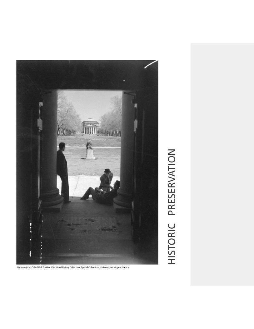

THIS PAGE INTENTIONALLY LEFT BLANK 90

HP 1 HISTORIC PRESERVATION 91
HP 1 HISTORIC PRESERVATION HP 1.1 GENERAL INFORMATION
Historic preservation is a major consideration at the University. The Historic District consists of 94 buildings within the Central Grounds areas including Thomas Jefferson’s Academical Village, and is considered historic landmarks. In addition, many other buildings are classified as historic landmarks or components of designated historic districts. The following is a list of historic buildings within the University. The Academical Village is listed separately as illustrated also in GENERAL REQUIREMENTS Figure 3.
HP 1.2 PRESERVATION GUIDELINES
The process of preservation is an ongoing task involving the identification, evaluation and treatment of historic resources, and formal policy for the care and treatment of these special buildings and landscapes should be embraced throughout all levels of the University. The management and conservation of historic resources must be a priority and requires cooperation between departments and disciplines throughout all phases of the work.
(1) Historically significant structures and landscapes must be recognized and
acknowledged to promote appreciation, understanding and respect for them.
(2) An active program of studying and recording the University’s historic resources must be pursued.
(3) Historic Structure Reports, Building Assessment Studies and Cultural Landscape Reports should be performed as needed on buildings and landscapes as a part of project planning.
(4) An active public outreach program involving presentations by preservation staff should be developed to communicate the findings and goals of the preservation framework plan to Facilities Management, the schools and departments within the University, and to the broader Charlottesville community.
(5) The permanent collection of records and information chronicling the development and evolution of the University’s historic resources should be maintained and enhanced.
(6) An active and ongoing program for listing resources on the National Register of Historic Places should be pursued.
(7) Archaeology must be incorporated into projects involving ground disturbances.

HP 1 HISTORIC PRESERVATION 92
(8) A design review process involving preservation specialists on the University staff should be implemented to evaluate proposed repairs on, alterations to and improvements of historic resources. Revisions to projects may be necessary to avoid altering or damaging the integrity of a building or landscape.
See also http://www.virginia.edu/architectoffice/historicpreservation.html for the Historic Preservation Framework Plan, Historic Structures Report, and other preservation-related information.
HP 1.2.1 CARE AND MAINTENANCE
Proper maintenance is fundamental to the long-term care and preservation of the University’s historic resources. In the on-going process of maintenance, the most appropriate action is the one which achieves the desired goal with the least negative effect on the historic resource. Realizing that these resources are the product of practices and materials not commonly employed in contemporary construction, the promotion and use of traditional methods, techniques, and skills for conservation should be embraced and promoted by the University to ensure appropriate repair and maintenance of the historic buildings.
(1) An active program of conservation of historic buildings, building fabric, and
landscapes must become an integral part of planning for repair and maintenance.
(2) The least intrusive methods of stabilization and repair should be employed when dealing with historic building fabric.
(3) Original fabric and character-defining features should be retained. Missing original features should be replicated faithfully without reproducing original failures or short comings.
(4) The University should maintain its staff of skilled trades people, who are knowledgeable in traditional materials and construction practices, and are capable of performing maintenance and repairs in a manner which is equal to or better than that found in the original construction of historic buildings.
(5) Completed work products must visually match work from the resource’s period of significance.
(6) Photographic and written documentation should be incorporated into all phases of work conducted on historic buildings and landscapes.
HP 1.2.2 ADAPTIVE USE OF BUILDINGS AND LANDSCAPES
Change is inevitable as the University evolves to continue serving its mission and should be managed to guard against unnecessary damage to historic resources. Improvements
HP 1 HISTORIC PRESERVATION 93
and alterations to historic resources should have minimal effect on the integrity of the building and/or landscape while at the same time extending the life and use of the resource. (1) Proposed changes should be evaluated against the building’s or landscape’s
significance to evaluate what effect alterations may have on the integrity of the resource.
(2) The original design and function of a building or site and its significant features must be considered in the planning, design and implementation of a building or landscape’s reuse. Ideally the use of buildings should be compatible with their original function and/or plan so as to minimize changes to the layout and volume of the spaces.
(3) New programs introduced into historic structures should be sympathetic to the fabric of the buildings and their associated landscapes.
(4) All efforts should be made to ensure that the installation and/or replacement of services and systems do not adversely affect the integrity of buildings and landscapes.
Alterations to buildings and landscapes to accommodate ephemeral uses and occupancy should be reversible. Permanent improvements to accommodate changes in use should be executed to a degree of quality equal to or exceeding that of the original construction.
(1) Past alterations that detract from the integrity of a historic resource should be
reversed when circumstances allow.
(2) Mothballing vacant or underutilized historic buildings according to the standards put forward by the National Park Service in Preservation Brief 31 should be employed to protect from deterioration and maintain them until an appropriate use allows for their occupancy or repair.
(3) Architectural fragments; significant elements and pieces of building systems removed from structures should be recorded, archived and protected by the University for future research and study.
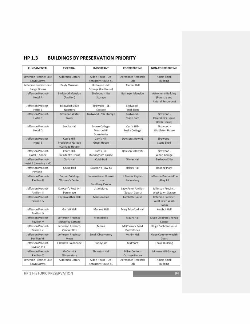
HP 1 HISTORIC PRESERVATION 94
HP 1.3 BUILDINGS BY PRESERVATION PRIORITY
FUNDAMENTAL ESSENTIAL IMPORTANT CONTRIBUTING NON-CONTRIBUTING
Jefferson Precinct-East Lawn Dorms
Alderman Library Alden House - Ob-servatory House #1
Aerospace Research Lab
Albert Small Building
Jefferson Precinct-East Range Dorms
Bayly Museum Birdwood - NE Storage (Ice House)
Alumni Hall
Jefferson Precinct-Hotel A
Birdwood Mansion (Pavilion)
Birdwood - NW Storage
Barringer Mansion Astronomy Building (Forestry and
Natural Resources) Jefferson Precinct-
Hotel B Birdwood Slave
Quarters Birdwood - SE
Storage Birdwood - Brick Barn
Jefferson Precinct-Hotel C
Birdwood Water Tower
Birdwood - SW Storage Birdwood - Stone Barn
Birdwood - Caretaker’s House
(Cash House) Jefferson Precinct-
Hotel D Brooks Hall Brown College-
Monroe Hill Dormitories
Carr’s Hill- Leake Cottage
Birdwood - Middleton House
Jefferson Precinct-Hotel E
Carr’s Hill- President’s Garage (Carriage House)
Carr’s Hill- Guest House
Dawson’s Row #1 Birdwood - Stone Shed
Jefferson Precinct-Hotel E Annex
Carr’s Hill- President’s House
Carr’s Hill- Buckingham Palace
Dawson’s Row #2 Birdwood - Wood Garage
Jefferson Precinct-Hotel F (Levering Hall)
Clark Hall Cobb Hall Gilmer Hall Birdwood Silo
Jefferson Precinct-Pavilion I
Cocke Hall Dawson’s Row #3 Halsey Hall Heating Plant
Jefferson Precinct-Pavilion II
Corner Building- Women’s Center
International House- Lorna
Sundberg Center
J. Beams Physics Laboratory
Jefferson Precinct-Poe Alley #1
Jefferson Precinct-Pavilion III
Dawson’s Row #4- Parsonage
Little Morea Lady Astor Pavilion (Squash Court)
Jefferson Precinct-West Lawn Garage
Jefferson Precinct-Pavilion IV
Fayerweather Hall Madison Hall Lambeth House Jefferson Precinct-West Lawn Wash
Room Jefferson Precinct-
Pavilion IX Garrett Hall Monroe Hall Mary Munford Hall Kerchof Hall
Jefferson Precinct-Pavilion V
Jefferson Precinct- McGuffey Cottage
Montebello Maury Hall Kluge Children’s Rehab Center
Jefferson Precinct-Pavilion VI
Jefferson Precinct-Cracker Box
Morea McCormick Road Dormitories
Kluge Cochran House
Jefferson Precinct-Pavilion VII
Jefferson Precinct-Mews
Small Observatory McKim Hall Kluge Commonwealth Court
Jefferson Precinct-Pavilion VIII
Lambeth Colonnade Sunnyside Midmont Leake Building
Jefferson Precinct-Pavilion X
McCormick Observatory
Thornton Hall Miller Center - Carriage House
Monroe Hill Garage
Jefferson Precinct-East Lawn Dorms
Alderman Library Alden House - Ob-servatory House #1
Aerospace Research Lab
Albert Small Building
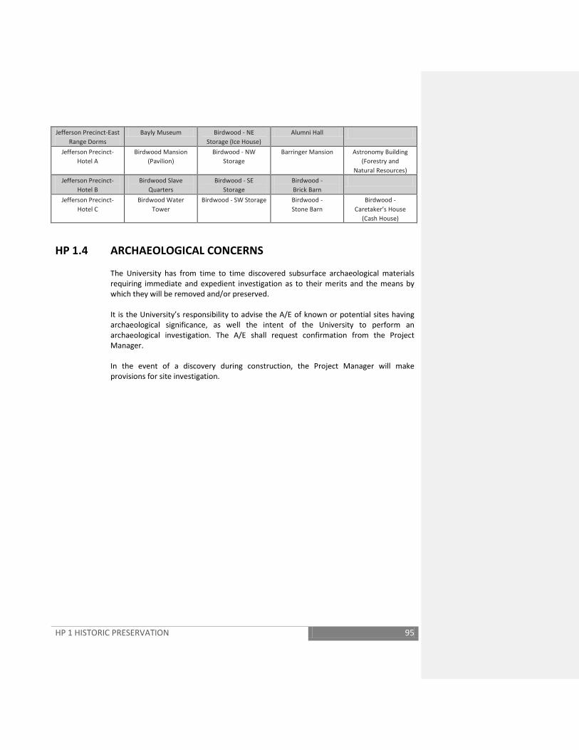
HP 1 HISTORIC PRESERVATION 95
Jefferson Precinct-East Range Dorms
Bayly Museum Birdwood - NE Storage (Ice House)
Alumni Hall
Jefferson Precinct-Hotel A
Birdwood Mansion (Pavilion)
Birdwood - NW Storage
Barringer Mansion Astronomy Building (Forestry and
Natural Resources) Jefferson Precinct-
Hotel B Birdwood Slave
Quarters Birdwood - SE
Storage Birdwood - Brick Barn
Jefferson Precinct-Hotel C
Birdwood Water Tower
Birdwood - SW Storage Birdwood - Stone Barn
Birdwood - Caretaker’s House
(Cash House)
HP 1.4 ARCHAEOLOGICAL CONCERNS
The University has from time to time discovered subsurface archaeological materials requiring immediate and expedient investigation as to their merits and the means by which they will be removed and/or preserved. It is the University’s responsibility to advise the A/E of known or potential sites having archaeological significance, as well the intent of the University to perform an archaeological investigation. The A/E shall request confirmation from the Project Manager. In the event of a discovery during construction, the Project Manager will make provisions for site investigation.

THIS PAGE INTENTIONALLY LEFT BLANK 96


THIS PAGE INTENTIONALLY LEFT BLANK 98

SW 1 SITEWORK GENERAL 99
SW 1 SITEWORK GENERAL SW 1.1 INTRODUCTION For requirements that effect site work and landscape design, see the following:
GENERAL REQUIREMENTS GR 3.6 University Landscape Architect, GR 3.7 AARB, GR 3.15.2 Asbestos Removal, GR 3.16 Lead-Based Paint Abatement, and GR 5.5 Building Systems Access & Equipment.
Additional information, subject to confirmation from the Office of the Architect for the University, is available at: http://www.virginia.edu/architectoffice/ . All projects involving site work and/or landscaping shall be reviewed by the University Landscape Architect, Facilities Management Landscape Superintendent, and Arboretum and Landscape Committee. Exterior signage shall be reviewed by the Architect for the University. The Project Manager shall coordinate review by the University Police Department for security and safety issues. Additional review may be determined for certain projects by the University Safety and Security Committee (lighting and shrubbery), and Architect for the University. Facilities Management Department of Energy and Utilities reviews site work documents related to any site utilities, the location of utilities in respect to landscaping, and established practices for installation.
SW 1.2 DESIGN DOCUMENT REQUIREMENTS Site plans shall be drawn at a minimum scale of 1"=20'-0". Building site contours shall be drawn at a maximum of 2'-0" intervals.
Profile views of all existing and new utilities shall be shown on the drawings. In addition to applicable code requirements, minimum separation of 12" vertically and 5'-0" horizontally, wall-to-wall, shall be provided between any two utilities and utilities structures (except as required by the Virginia Uniform Statewide Building Code and Virginia Department of Health Regulations for water and sanitary lines and structures).
Formatted: Heading 2, Indent: Left: 0"
SW 1 SITEWORK GENERAL 100
SW 1.3 Not Used.
SW 1.4 UTILITY TRENCH CUTS IN ROADWAY
Utility trench cuts in roadways shall be limited to 200’ maximum and shall be covered with traffic rated steel plates at the close of construction activities for the day.
SW 1.5 UNDERGROUND OR ABOVE GRADE PETROLEUM STORAGE TANKS No underground storage tanks (USTs) are permitted without documented approval of the CFO. Only double-walled USTs will be considered for installation. Drawings and specifications for any tank, above grade or underground, shall be reviewed and approved by the University Office of Environmental Health and Safety for compliance with both Federal Department of Environmental Quality (DEQ) and more restrictive Spill Prevention, Countermeasures and Control (SPCC) plan established by a negotiated agreement between the University and the Federal Environmental Protection Agency (EPA). The University is required by DEQ to obtain building permits for tanks installed on or removed from University property. Standards: Technical standards related to USTs and ASTs are contained in the State Water Control Board Regulations: 9VAC25-580, Underground Storage Tanks (UST): Technical Standards and Corrective Action Requirements and 9VAC25-91, Facility and Aboveground Storage Tank (AST) Regulation.
Local Building Official Authority: The University Building Official is the authority having total jurisdiction. The Project Manager will provide the University Building Official copies of the appropriate sheets/sections of the specifications/drawings.
SW 1.6 OIL INTERCEPTORS
Parking garages and large parking lots where wash-down maintenance will be performed shall be provided with oil interceptors designed to established standards for size and water quality control. There shall be adequate access for cleaning all areas of the separator with a vacuum pump. Compartments shall be constructed horizontally, not vertically. A minimum of one (1) access point into each compartment within the separator shall be provided. In addition, no access points shall be further apart than ten (10) feet regardless of number of compartments. Access covers shall have a minimum opening dimension of twenty four (24) inches in diameter.

SW 2 SITE PREPARATION 101
SW 2 SITE PREPARATION SW 2.1 MUD AND DIRT CONTROL
For projects requiring removal of excavation material from the site, the specifications shall require the contractor to provide a workable truck wheel wash facility complete with frost proof hydrant for a 3/4" hose. Details shall be shown on the contract documents. Specifications shall stipulate that the contractor shall remove mud or dirt deposited on roadways within one hour of occurrence.
SW 2.2 PLANT PROTECTION Trees, shrubs and planting beds within the Contract Limit Lines are to be protected with rigid fencing (wood or chain link) to prevent damage by cranes and all external construction activities. Selection of trees to be protected shall be coordinated through the Facilities Management Landscape Area Supervisor specifically applicable to the general academic University Grounds or the Health System (Hospital and Medical School). Underground utilities shall be located so that construction will not damage or destroy the plants to remain. Utility trenching shall not be located closer than 1'-0" for each 1" in diameter, with a minimum of 5’-0” and a maximum of 20'-0" for trees to remain. Damaged trees and plants shall be restored to the satisfaction of the Facilities Management Landscape Area Supervisor. The parking of vehicles and storage of any construction materials shall not occur under the drip lines of trees to be protected.
SW 2.3 EARTHWORK All suitable topsoil shall be stockpiled in a location designated by the University for reuse in the project. Clean fill, other than that used for backfilling, may be disposed of on the Grounds when approved by the CFO. All other surplus material (excavated material and construction debris) shall be disposed of by the contractor off-site legally. Stone over 1", debris, wood, metal etc. shall be removed from the top 6" layer of final backfilling for all areas to be seeded or planted. Specifications shall state that where hazardous materials are encountered in sitework, work shall be stopped and the Project Manager notified. The A/E shall consider the recommendations in the geotechnical/soils report in developing the design.
SW 2 SITE PREPARATION 102
SW 2.3.1 - Drawing details of the following conditions will be required: (1) Over-excavation and replacement with suitable materials.
(2) Subsurface profiles (boring logs) and limits showing the extent of rock, existing
fill materials, water and existing unsuitable bearing materials. (3) Specific drawing notes stating that earthwork details are included in the Base
Price/Bid. Earthwork beyond the extent indicated will be considered for an extra cost, only if necessary and approved by the A/E, and not a result of the contractor’s failure to maintain site/excavation stability, drainage or protection from frost penetration.
SW 2.3.2 - Earthwork Specifications shall be definite, not general. (1) Coordinate specifications with the drawings.
(2) Include a geotechnical/soils report in the appendix to the specifications and a
disclaimer stating that the report is not part of the contract documents each time this report is referenced.
(3) Specifications for materials and instructions shall state whether they are
included in the Base Price/Bid or will be an extra cost item. (4) Rock excavation shall be included in the Base Price/Bid to the extent that
locations are sufficiently identified in the geotechnical/soils report. Earthwork specifications shall include soil and aggregate material definitions for all materials used in the project. The soil materials shall be defined by a recognized soil classification system, such as the Unified Soil Classification System or the AASHTO Soil Classification System. The definitions below are by the Unified System. The aggregates shall include gradations required for each material. Note: Unedited master or standardized specifications often are too conservative in defining soil materials - often eliminating the on-site soils as acceptable materials, even for general fill/backfill. Quality control is also often not provided in the form of aggregate gradations. All A/E standard specifications shall be edited to conform to the following requirements: SW.2.3.3 - Structural fill/backfill: Generally restricted to GW, GP, GM, SM, SW, and SP unless other materials are specifically approved by the Soils Engineer or firm that conducted the on-site soils evaluations. SC, CL, and ML might be considered in some situations with the approval of the Soils Engineer. SW.2.3.4 - General fill/backfill: Includes all classifications of materials noted above. Unsuitable Materials: Includes OL, MH, CH, OH and PT, saturated material which in the judgment of the Soils Engineer cannot be aerated to be made acceptable, uncompacted
SW 2 SITE PREPARATION 103
fill (for structural bearing conditions), fill with unacceptable quantities of non-soil products, or other materials judged unsuitable by the Soils Engineer.
SW.2.3.5 - Aggregates: They may include porous backfill, pipe bedding, under slab fill, any special blend or open-graded material required for a special bearing or drainage use. Moisture content of soil materials: Laboratory tests are generally conducted on samples to determine the maximum density of soils, usually achieved at optimum moisture content. Field conditions during construction prevent attaining and maintaining the optimum moisture content. This requires that a tolerance for departure from this optimum must be specified. This tolerance is generally specified in the range of plus or minus three to five percent (3% to 5%) from the optimum moisture content without significantly affecting the ability to achieve the specified density. SW. 2.3.6 - Quality Assurance/Testing: The specifications shall list the tests required to be performed on the work (i.e. ASTM, AASHTO, VDOT or other test procedures) and stipulate the values to be achieved.
SW 2.4 SITE CLEARING All logs, stumps, brush, wood and refuse shall be disposed of off the University Grounds in an approved landfill. On-site burning shall be prohibited.
SW 2.5 SITE DEMOLITION When buildings are to be removed, procedural requirements and approval are required prior to demolition. The Project Manager, through Space and Real Estate Management shall have obtained required State approval. The University shall perform an asbestos and lead paint survey and the information shall be included in the contract documents. All tree removals require prior approval by the Arboretum and Landscaping Committee.
SW 2.6 SOIL TREATMENT A licensed professional shall chemically treat all new excavations for termite and insect infestation. Specify under slabs, along foundation walls, around all openings and protrusions in slabs on grade.
SW 3 SITE DEVELOPMENT 104
SW 3 SITE DEVELOPMENT
SW 3.1. PLANTING Planting shall be in compliance with an approved landscape plan. See SITEWORK SW 1.1 Introduction. The selection of plant material and the planting and maintenance of trees, shrubs and herbaceous plants must be consistent with the current AAN American Standard for Nursery Stock.
SW 3.1.1 PLANT SELECTION Prior to planting, all plant material must be approved by the Facilities Management Landscape Area Supervisor as healthy specimens of the specified planting.
SW 3.1.2 SOIL PREPARATION Soils in areas to be planted that are compacted above 85% maximum density shall be mechanically loosened to a minimum uniform depth of 24” below final grade. Planting holes shall be excavated one day prior to planting and tested for soil porosity. Holes left open overnight should be roped off for public safety.
Soil conditions, which are inadequate for sustaining the growth and development of plants, must be reported to the Facilities Management Landscape Area Supervisor and/or the University Landscape Architect. Inadequate soil conditions must be addressed prior to planting.
SW 3.1.3 PLANTING PROCEDURES
The width of each planting hole should be three times the size of the root ball. The depth of the hole shall be 2’’ less than the distance from the bottom of the root ball to the root collar. The bottom and sides of the each hole should be scarified to encourage root development. Upon planting, all plants must be inspected to ensure that the root collar is exposed. Any dirt or mulch covering the root collar should be removed at this time. Inspection of plants will be made by the Facilities Management Landscape Area Supervisor at completion of planting.

SW 3 SITE DEVELOPMENT 105
SW 3.1.4 TREE PLANTING To preserve the assets of trees and manage the assets of underground utilities, new trees shall not be planted: (1) Within ten feet of any existing underground utility lines with joints
(2) Within five feet of any existing underground utility lines without joints (joints may occur when they are at least ten feet from the tree center in both directions)
(3) Where new storm and sanitary sewer piping alignment cannot be avoided within ten feet of an existing or new tree, use HDPE butt-welded pressure piping
SW 3.1.5 WARRANTY PERIOD
The contractor shall maintain all plantings for the duration of the warranty covering plant material. The contractor’s responsibilities also include the protection of plantings as necessary during the warranty period, including pest control, pruning and watering.
SW 3.2 SITE LIGHTING Lighting is an important element in security design. An effective security lighting design should consider all elements of the site: facility location and usage, the landscape or planting plan, and site walkways and traffic patterns as well as the impact of the lighting on the surrounding areas. Light pollution, trespass and glare to surrounding properties should be minimized.
SW 3.2.1 DESIGN REQUIREMENTS
All exterior lighting fixtures on Grounds shall conform to the University of Virginia's Exterior Lighting Study and the Office of the Architect's Landscape Typologies and Standards, both documents available at the Facility Management's Resource Center or at http://www.virginia.edu/architectoffice/Landscape.html and UVA FM Resource Center. Off Grounds facilities shall comply with the following: Light fixtures and poles are to be cast iron. When approved by the Director of Facilities Planning, and Construction, aluminum poles of similar design may be used in locations where it can be demonstrated that vehicular impact is not probable.
SW 3.2.2 ILLUMINATION REQUIREMENTS – HORIZONTAL
Horizontal Illumination Requirements Location/Area Foot-candle levels* Ratios
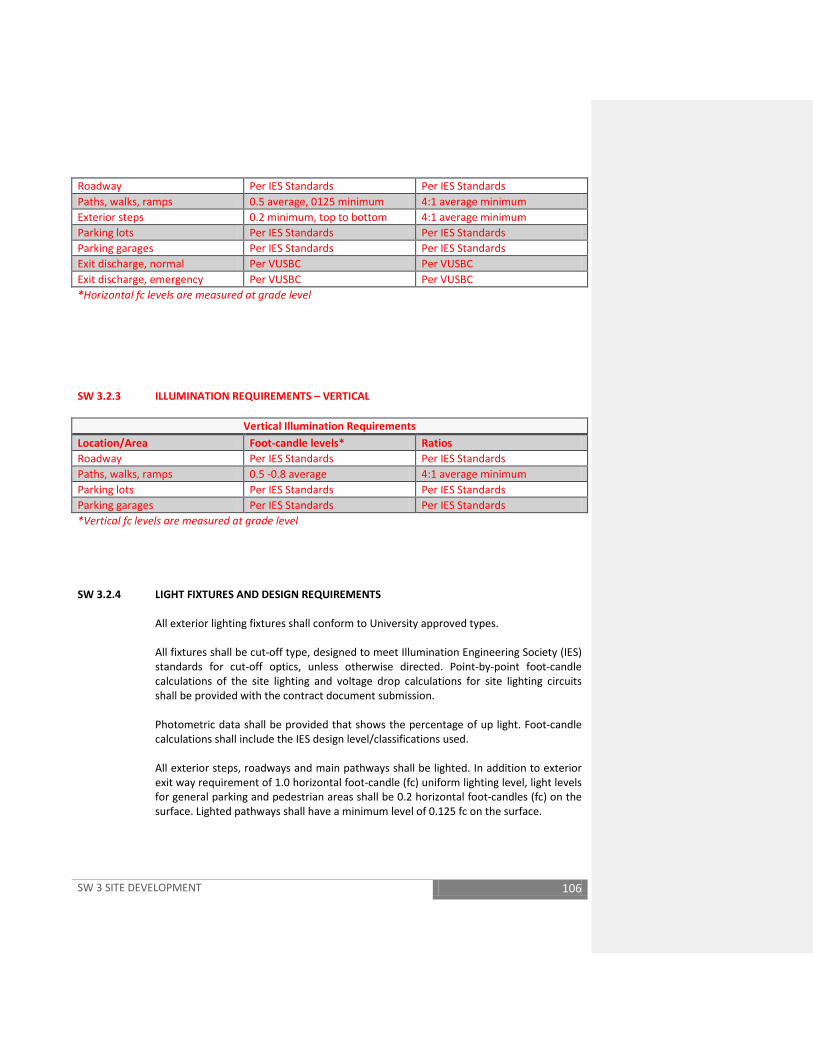
SW 3 SITE DEVELOPMENT 106
Roadway Per IES Standards Per IES Standards Paths, walks, ramps 0.5 average, 0125 minimum 4:1 average minimum Exterior steps 0.2 minimum, top to bottom 4:1 average minimum Parking lots Per IES Standards Per IES Standards Parking garages Per IES Standards Per IES Standards Exit discharge, normal Per VUSBC Per VUSBC Exit discharge, emergency Per VUSBC Per VUSBC *Horizontal fc levels are measured at grade level
SW 3.2.3 ILLUMINATION REQUIREMENTS – VERTICAL
Vertical Illumination Requirements Location/Area Foot-candle levels* Ratios Roadway Per IES Standards Per IES Standards Paths, walks, ramps 0.5 -0.8 average 4:1 average minimum Parking lots Per IES Standards Per IES Standards Parking garages Per IES Standards Per IES Standards *Vertical fc levels are measured at grade level
SW 3.2.4 LIGHT FIXTURES AND DESIGN REQUIREMENTS
All exterior lighting fixtures shall conform to University approved types. All fixtures shall be cut-off type, designed to meet Illumination Engineering Society (IES) standards for cut-off optics, unless otherwise directed. Point-by-point foot-candle calculations of the site lighting and voltage drop calculations for site lighting circuits shall be provided with the contract document submission. Photometric data shall be provided that shows the percentage of up light. Foot-candle calculations shall include the IES design level/classifications used. All exterior steps, roadways and main pathways shall be lighted. In addition to exterior exit way requirement of 1.0 horizontal foot-candle (fc) uniform lighting level, light levels for general parking and pedestrian areas shall be 0.2 horizontal foot-candles (fc) on the surface. Lighted pathways shall have a minimum level of 0.125 fc on the surface.
SW 3 SITE DEVELOPMENT 107
In addition to required exit ways described above, all steps shall have a continuous 0.2 fc path from the top to the bottom. Average-to-minimum uniformity shall not exceed 4:1. All new or replacement site lighting in proximity to the University’s astronomy observation facilities shall be reviewed by designated personnel of Facilities Management and the Department of Astronomy. See Figure 13 Observatory-Sensitive Zone. On Grounds: Fixtures and Poles on Grounds shall be as specified in the lighting study Off Grounds: Fixtures and poles shall be as follows: All exterior lighting fixtures are to use metal halide HID lamps or LED only.
Acceptable manufacturers and product descriptions are:
Fixtures: (1) Spring City Edgewater EFED-###-MH-UVA with frosted panels
(2) Holophane UVA ### MHOOx63RG Antique Octagon
(3) King K56-S-R-EAO-V-###-MH-277-UVA Cutoff
(Lamp wattages and IES distribution type to be determined by layout and design.) Poles: (1) Spring City 12 ESCT/7 Series
(2) Holophane “West Point”, 12’
(3) King Luminaire 20” Octagonal, 12’
When approved by the Director of Facilities Design and Construction, aluminum poles of similar design may be used in locations where it can be demonstrated that vehicular impact is not probable. “Shoe Box” type fixtures for parking lots and roadways are generally applicable to other areas of the University, subject to verification by the Project Manager and/or approval of the Landscape Architect for the University. See Figure 12. Lens shall be impact-resistant tempered glass with a minimum 0.125” thickness.
SW 3 SITE DEVELOPMENT 108
SW 3.2.5 INSTALLATION REQUIREMENTS The cost of all light fixtures, controls, all associated mounting equipment and their installation shall be incorporated into the project budget. Architect/Engineer shall specify the light fixtures based on the exterior lighting study; provide lighting and voltage drop calculations based on the light fixtures specified.
For on Grounds: Site lighting poles and fixtures will be “owner furnished owner installed” (OFOI). Owner (Facilities Management Department of Energy and Utilities) will provide pole and light fixture and will make final connections. Contractor shall provide necessary conduit and shall stub out of the building to a handhole box, and shall provide the contactor, controller photocell and wiring to the handhole.
Owner will install all conduit, wiring, foundations and poles and fixtures beyond the handhole. The contractor shall coordinate with Owner for notification as to the schedule. All other lighting such as building mounted, patio, courtyard and exterior steps, and bollard light fixtures shall be “contractor furnished contractor installed” (CFCI). Owner will not install these fixtures. (Highlighted is new, everything below is same) For off Grounds: All lighting fixtures shall be furnished and installed by contractor. Step light fixtures built into concrete or masonry shall be constructed of corrosion resistant material, and listed for wet location installation. Site lighting shall be photocell controlled in logical groups. Individual unit photocell controls are to be used only where grouping of lights is not practical. Site lighting fixtures are to be powered with underground copper wiring in 1-1/4” PVC conduit. Burial depth shall be 18” minimum. Circuit wire sizes shall be such that site lighting voltage drops do not exceed the following: (1) 2% for new site lighting circuits
(2) 3% total for existing circuits to which lights are added
All pole and post-mounted lighting fixtures shall be numbered on the construction documents and on the erected fixture. Obtain fixture ID number and label size/style from Facilities Management Department of Energy and Utilities.
“As-built” or record document plans for outdoor lighting shall provide a utilities lighting chart with fields designating the following: (1) Light fixture ID number (from Energy and Utilities)
SW 3 SITE DEVELOPMENT 109
(2) Lamp type (adequate for ordering lamps)
(3) Fixture Manufacturer and catalog/model number
(4) Electrical feed (building name and number, and panel designation)
(5) Watts (lamp and fixture wattage)
(6) Voltage
(7) Pole height
(8) Pole Manufacturer and catalog/model number
SW 3.3 SIGNAGE New buildings and major building renovations shall provide permanent exterior signage in compliance with the established University Exterior Signage Standard Manual. This manual may be viewed and printed from the Architect for the University website: http://www.virginia.edu/architectoffice/ .
The A/E is to develop a conceptual signage plan consistent with the exterior signage standard manual for approval by the University Landscape Architect. Construction signs, when approved by the Project Manager, shall be limited to a maximum 4’-0” x 6’-0” sign erected at the contractor’s expense, with lettering in compliance with the University Exterior Signage Standard Manual. See Facilities Management Division 1 Specifications Guidelines, 01580, available at website http://www.fm.virginia.edu/fpc/Links.htm or see also the Office of the Architect for the University website: http://www.virginia.edu/architectoffice/designreview.html.
SW 3.4 PAVING AND CURBS Minimum slope for all paved surfaces shall be 1%. Maximum slopes for streets, service drives and parking lots shall be 8%. Curbs shall comply with Standard 6” Curb, CG-2, Virginia Department of Transportation (VDOT). Use curb and gutter complying with VDOT CG-6 Standard 6” Curb and Gutter to match an existing condition or within City of Charlottesville streets.
Painted striped crosswalks shall be provided at all road intersections.
Unless modified by documented site conditions and geotechnical recommendations, asphalt paving is to be:
Course/VDOT Specification Roads Parking Pedestrian walks Surface/SM-2A or 9 -52A” 2” 1 ½ ” 2”
SW 3 SITE DEVELOPMENT 110
Binder/BM-2 or 25 – 0” 3” 2” Not applicable Sub-base/21A 10” 6” 6”
Sub-grade compaction *100 95 95 *Maximum dry density (ASTM D698, Method D)
New or improved roads of sufficient width shall include bicycle lanes on both sides of the street. Demarcation of the bicycle lanes through striping and signage shall be consistent with established VDOT standards.
SW 3.4.1 PAVEMENT AT UTILITY TRENCHES
Pavement thickness at utility trenches shall be a minimum of one-and-a-half times (1.5X) existing pavement thickness or as noted above, whichever is higher. Backfill in utility trenches under pavements shall be VDOT #21A above top of bedding to underside of pavement.
SW 3.5 SIDEWALKS The Office of the Architect for the University shall establish use of concrete or brick over concrete sidewalks as part of the project design criteria. If not so determined, the choice shall be in consultation with the University Landscape Architect. The minimum sidewalk width shall be 6’-0”. Where used for truck access minimum width shall be 10’-0”. Except where restricted by urban site needs, sidewalks will be separated from curbs by planting areas for pedestrian safety. Where separation is not feasible, comply with Figure 14 and Figure 15.
SW 3.5.1 CONCRETE SIDEWALKS
Sidewalks shall be 5” minimum thickness, 3000 psi air-entrained concrete, reinforced with welded wire fabric, 6x6 W2.9x2.9, over 6" compacted aggregate stone base. Joints shall be sawed or tooled at a maximum of 6'-0" o.c. Walks to be float finished with 2" troweled edging. See Figure 14. Where sidewalks abut existing structures, expansion joints shall be provided. See BUILDING ENVELOPE, BE 1.2.2 Fiber Reinforced Concrete. New construction projects shall use an approved concrete if appropriate for color matching existing concrete. Questions about color should be referred to the Office of the Architect for the University, unless the use of color is established as part of the design criteria determined by the Architect for the University.
SW 3.5.2 BRICK SIDEWALKS
Brick sidewalks shall be constructed on concrete per Figure 15. The concrete, other than finish, shall comply with SW 3.5.1 above. Brick patterns, more typically herringbone, shall be determined in University design criteria. Where not predetermined, questions

SW 3 SITE DEVELOPMENT 111
may be directed to the Office of the Architect for the University. For guidelines regarding the selection of brick patterns for walks and paving areas, see the 1998 Landscape Master Plan.
SW 3.6 EXTERIOR STEPS All exterior stairs shall have handrails on both sides regardless of the number of risers. Where handrails would exceed 5’-0” center-to-center, an intermediate handrail is required. For monumental stairs, whether required fire egress exit ways or not, handrails shall be located along the most direct path subject to approval of the University Building Official Review Team
Consideration shall be given to professionally recognize proportioning of tread and riser dimensions, as well as to maximum riser and minimum tread requirements. Positive drainage (1.5 to 2.0 percent slope) shall be achieved to prevent accumulation of water. Where post-mounted hand railing supports occur, careful consideration with drawing details shall be given to the embedment of posts to minimize deterioration of the posts and/or the concrete slab or system into which it penetrates. Whenever this embedment occurs in a pre-cast concrete system specifications shall be explicit regarding galvanization of the embedded sleeve and any anchors (as a unit after any welding) prior to placement in the form work.
SW 3.7 BICYCLE RACKS The design of all University facilities, or major site renovations, shall include adequate bicycle storage with permanently installed racks. See Figure 16. Questions about the location and design of bicycle storage may be referred to the Office of the Architect for the University.
SW 3.8 EMERGENCY TELEPHONES SW 3.8.1 EMERGENCY TELEPHONES
New buildings, new parking lots and major site work projects shall provide the location(s) for emergency telephone(s) that are handicapped accessible, hands free operated, and located on or near lighted walkways providing visibility and comfort in their use. Project Manager shall determine approved locations and type(s) of installation in consultation with the University Safety and Security Committee. Two types of emergency telephone styles are applicable. In all installations the telephone shall be University provided and installed on or in the assembly. The type applicable to most locations is a Facilities Management fabricated and installed assembly as illustrated in Figure 8. Specifications shall state the requirements of the

SW 3 SITE DEVELOPMENT 112
contractor. In some cases Facilities Management will be fully responsible for installation including necessary wiring and telephone cabling to a University point of connection. Facilities Management Department of Utilities will procure and install the Figure 8 fabricated assembly including the telephone and light fixture. For areas determined by the University Safety and Security Committee and large parking lots (more than 49 cars), the use of pre-manufactured emergency telephone assembly is appropriate. For each additional 99 parking spaces, an additional emergency telephone is required. Where approved by the University Landscape Architect this “tower” type assembly may be taller than 8-feet for large parking lots for visibility over vans and similar taller vehicles. Where the “tower” type emergency telephone is applicable, the design shall be similar to Gai-tronics Corporation Model 234 Stanchion and/or model ETP-MT/R by Talk-A-Phone Co., and shall be ADA compliant. Color(s) shall be approved by the University Landscape Architect. Power for emergency telephones is to be an emergency circuit where available.
SW 3.9 BENCHES
Benches approved for use at the University are:
(1) Kingsley Bate “Hyde Park” #HP60 (2) Country Casual “Mendip” #4603 (3) Gardenside “Parkside Bench” #2606
SW 3.10 TRASH RECEPTACLES Trash and ash urn receptacles will be University furnished and installed. For the A/E’s consideration in the design of new or renovated sites, the receptacles will be Victor Stanley Bethesda Ironsites Series Model S-42 (trash) and Model S-20 (stand-alone ash urn) or an equivalent. Trash and ash urn receptacles shall be painted black. Ash urns will not be integral with trash receptacles.
SW 3 SITE DEVELOPMENT 113
SW 3.11 RECYCLING RECEPTACLES
Recycling receptacles will be University furnished and installed. The Project Manager shall determine in consultation with University Landscape Architect and the Office of Facilities Management Recoverable and Disposable Resources where and what kind of recycling receptacles are deemed applicable. For the A/E’s consideration in the design of new or renovated sites, the Project Manager will provide information on the selected receptacles.
SW 3.12 BOLLARDS Three types of bollards are approved for use at the University. Choice of the appropriate bollard for a project site shall be coordinated through the Project Manager in consultation with the Office of the Architect for the University. General guidelines include:
SW 3.12.1 METAL BOLLARD TYPE I A Newburyport bollard shall be utilized on all sites within the Historic Grounds, except in alleys. It may also be used throughout the University in sites where obstructing vehicular traffic on wide areas of paving is the primary purpose. Where bollards are not to be removable for University vehicular or emergency vehicle access, cast iron bollard will be used. For removable bollards a cast aluminum bollard will be used. The University Landscape Architect shall approve removable bollards of a similar style on a case-by-case basis, unless the University adopts a new standard. Figure 17 illustrates a removable bollard. These bollards should be primed and painted to match the color Sherwin Williams #94341 Rookwood Shutter Green. When incorporated as part of a project, the drawings and specifications shall state that these bollards are owner furnished and contractor installed. Site preparation and finishing shall be by the contractor.
SW 3.12.2 METAL BOLLARD TYPE II A locking metal bollard, Figure 18, shall be used throughout the University, including the Historic Grounds, where restricting vehicular access to sidewalks. These bollards should be primed and painted to match the color Sherwin Williams #94341 Rookwood Shutter Green.
SW 3.12.3 WOOD BOLLARD A wood bollard, Figure 18 shall be used in the alleys of the Historic Grounds.

SW 3 SITE DEVELOPMENT 114
SW 3.13 DUMPSTER PADS
Reinforced concrete pads, sized to include the front wheels of the truck, are to be constructed for all dumpster pad sites.
SW 4 SITE DRAINAGE SYSTEMS 115
SW 4 SITE DRAINAGE SYSTEMS SW 4.1 BUILDING DRAINAGE SW 4.1.1 LAND DISTURBANCE
Any project that disturbs the land in excess of 500 square feet, whether increasing or decreasing impermeable areas, is required to address storm water management. This more restrictive threshold is related to University property within the various watersheds of Moore’s Creek and Meadow Creek. Facilities Management Directive 523 when published will address this in greater detail.
SW 4.1.2 BUILDING AND ROOF DRAINAGE All building roof drainage, including external downspouts, areaway drains, and foundation drains shall be connected to a storm drainage system. Connections shall preferably be made to a manhole or a drop inlet directly. Where the preferred connection is not feasible or economically justified, the connection shall be to the storm sewer with a “Y” a maximum of 50-feet away from the building. Provide cleanout at roof drain and at a change in direction of any drainage piping. Where a storm system is not available, a new system shall be provided. Exceptions to the above shall be coordinated with the Facilities Management Department of Energy and Utilities, and if necessary the CFO, through the Project Manager.
SW 4.2 STORM SEWER SYSTEMS
SW 4.2.1 PIPING AND INSTALLATION Perforated polyvinyl chloride pipe surrounded by stone wrapped in geotextile fabric shall be used for all foundation and retaining wall drainage systems. Class III reinforced concrete pipe, minimum 15” size, shall be used for all infrastructure systems. HDPE pressure or HDPE double wall corrugated pipe may be used for mains under 24”. See SITEWORK SW 3.1.4 Tree Planting, for piping within ten feet of new or existing trees. Polyvinyl chloride (PVC) Schedule 40, solvent welded piping is permitted:
1) For yard drains, 8” minimum through 12” maximum
2) For roof, area drains, and foundation drains, 4” to 6” as required for single drain lateral; and 8” to 12” maximum for multiple drain collector lateral.
SW 4 SITE DRAINAGE SYSTEMS 116
Minimum cover on pipe shall be 24”. Slope of piping shall result in self-cleaning velocity (2-fps minimum) for the diameter of piping used. Storm sewer piping on a 20% or greater slope shall be secured with concrete anchors.
SW 4.2.2 MANHOLES
Manholes are required: (1) At change of direction for main storm sewer piping (2) At intervals not exceeding 400-feet in a straight run
By exception, drop inlets having a minimum inside diameter of 48” may be used in lieu of above manhole requirements.
Manholes shall have a minimum 48” inside diameter with shaped flow troughs at bottom. Manhole covers shall be heavy-duty traffic rated, providing a minimum 24” clear opening for access. Patch precast manhole joints with non-shrink grout inside and outside. Apply bitumastic/coal tar waterproof coating from outside Pipe connections to new manholes and inlets shall be with flexible rubber boots. At existing structure install sleeve prior to connection using flexible rubber boot.
SW 4.2.3 INLETS AND STRUCTURES Curb inlets shall be used for all surface drainage for roadways and parking lots. All grates for yard inlets shall meet handicapped accessibility standards, unless otherwise authorized by Facilities Management in writing. Grate inlets shall be used for all lawn areas. Inlet grates shall be bicycle-safe and oriented with the long axis of the openings perpendicular to the direction of bicycle traffic.
The tops of all structures shall be flush with the pavement surface. Inlet structure grating shall be heavy-duty traffic rated, providing a minimum 24” clear opening for access. Minimum inside size for drop inlets shall be 24” with up to 18” pipe diameter and 4-feet maximum depth. Minimum inside size of drop inlet shall be 48” for pipe size larger than 18” pipe diameter or greater than 4-feet depth. Area drains, cleanouts and yard drains installed with minimum pipe size and cover shall use shallow cast iron fittings or heavy-duty HS 20.traffic rated fittings installed in concrete pad at surface.
SW 4 SITE DRAINAGE SYSTEMS 117
VDOT standard structures are to be used except where not practical. The intent of this requirement includes minimal dimensions as accessibility for maintenance. In historic precincts or locations, smaller dimensioned structures will require approval on a case-by-case basis by Facilities Management.

THIS PAGE INTENTIONALLY LEFT BLANK 118
SW 5 SITE PIPING SYSTEMS
SW 5.1 SEWER PIPING Piping diameter size shall be a minimum of 4" for laterals and 8” for mains. Provide a 3'-0" minimum ground cover. Sewer piping shall be located as approved by the Facilities Management Department of Utilities and other applicable authorities when located in streets, right-of-ways or easements not on University property. Sewer piping shall not be located within areas of flooding or drainage channels. See SITEWORK SW 1.1 Introduction. Every effort shall be made for domestic waterlines to cross above sanitary sewer in accordance with applicable code requirements. If site conditions do not allow this to happen, domestic water lines may cross under sanitary sewers constructed with joint-less or welded joint pipe in accordance with code, supported for twenty feet on either side and tested for leaks at 50-psi internal pressure. Pipe shall be cast iron (CI), ductile iron (DI), H2, HDPE pressure pipe or solvent weld jointed PVC, Schedule 40. (At Heat Plant, HDPE or PVC Pipe is not permitted). Minimum slope of piping shall result in self-cleaning velocity (2 fps minimum) for the diameter of piping used. Sewer piping on a 20% slope or greater shall be secured with concrete anchors.
SW 5.2 SEWER MANHOLES Provide a sanitary sewer manhole adjacent to all buildings to which laterals (maximum 20-feet length) from building are preferably connected directly. Provide a clean out at the building for a lateral longer than 20-feet, not to exceed 50-feet maximum. Manholes shall occur at a change in direction and at a maximum of 200 feet in a straight run. Manholes shall have a minimum 48” inside diameter with flow troughs at bottom. Manhole frame and cover shall be heavy-duty traffic rated, providing a minimum 24” clear opening for access. Manholes with an invert change of 18” or two times the inlet pipe inside diameter, whichever is greater, shall be provided with drop piping outside the manhole. Pipe connections to manholes shall be made with flexible rubber boots. At existing manhole install sleeve for connection. Use flexible rings, mechanical clamps, grout and water stop for a leak-proof connection. Precast manhole joints (inside and outside) shall be filled with non-shrink grout and finished smooth. Manholes shall be coated from inside with vapor/moisture penetration

SW 4 SITE DRAINAGE SYSTEMS 119
preventing epoxy coating, and from the outside with bitumastic/coal tar based waterproof coating. Cleanouts shall be installed in concrete pad flush with surface for HS 20 rated installation.
SW 5.3 EXTERIOR DOMESTIC WATER AND CHILLED WATER PIPING
Piping mains shall be a minimum of 6" in diameter. Domestic water piping shall have a minimum of 3'-0" ground cover. Chilled water piping shall have a minimum of 4’-0” ground cover. All buried water lines shall have a sand or stone dust bed and cover.
Valves shall be installed at all piping branch-offs. Underground water distribution pipe shall be asphalt coated, cement lined ductile iron, Class 52 or higher, with flexible restrained joints. The buried chilled water supply pipe shall be insulated. Field installed rigid foam glass with 50 mil poly jacket is preferred; however, pre-insulated double wall pipe is acceptable. New chilled and domestic water branches shall preferably be connected to existing mains with full size tees; reducing tees or wet taps can be only be used with prior approval of UVa Energy and Utilities Department. Resilient seat gate valves shall be provided at the connection point to the main; where full size tees are used the valve shall be full size and upstream of any reducer. The entry point into buildings shall be with factory flanged ductile iron, Class 53 or higher. Water lines 2 ½” and smaller shall be copper type "K". Water lines shall be tested to 200 psig. Domestic water lines shall be bacteria tested.

THIS PAGE INTENTIONALLY LEFT BLANK 120


THIS PAGE INTENTIONALLY LEFT BLANK 122

BE 1 BUILDING ENVELOPE 123
BE 1 BUILDING ENVELOPE BE 1.1 GENERAL INFORMATION
The building envelope shall incorporate materials and detailing consistent with a building life span of not less than 50 years, with optimized energy conservation and management, and environmental sensitivity.
BE 1.2 CONCRETE
SPECIAL REQUIREMENTS FOR CAST-IN-PLACE CONCRETE The Specifications shall contain the following requirements in §03300 - Cast-in-Place Concrete:
ACI 301, Specification for Structural Concrete for Buildings (current edition) shall be incorporated by references as the standard unless otherwise modified. Field tests of fresh concrete shall include Sampling - ASTM C172, Slump - ASTM C143, Making and Curing Test Specimens - ASTM C31, Air Content - ASTM 231 or ASTM C173, and Unit Weight - ASTM C138. The University shall engage the Services of the concrete testing laboratory to perform the sampling, cylinder preparation and delivery, testing and reporting. The contractor shall be responsible for adequate advance Notice to the testing laboratory for the contractor’s concrete pours/placement. Individuals performing the field tests of fresh concrete shall have proper training, qualifications, and be certified as a Concrete Field Testing Technician-Grade I by the American Concrete Institute or other recognized certification conforming to the minimum requirements of the American Concrete Institute's certification which requires the successful completion of a written and performance examination on the applicable ASTM test methods of this section.
BE 1.2.1 GENERAL
Except for mud concrete, minimum concrete strength shall be 3,000 psi. Exposed aggregate surfaces shall not be used. Specifications shall state that positive measures are to be taken to assure that exposed concrete surfaces are not vandalized before initial set. Refinishing of vandalized surfaces shall be performed by contractor at no cost to the University.
BE 1 BUILDING ENVELOPE 124
The use of wet curing shall be required. If approved, the use of a curing compound is to be limited where application of moisture is impractical, where application of such compounds will not jeopardize appearance of concrete or bond to additional concrete, and where concrete surface is to be finished with paint, tiles, waterproofing, roofing or chemical seal. Use type 1 curing compound (except use of type 2 on surfaces exposed to sunlight) applied with uniform thickness and other recommendations by manufacturers.
BE 1.2.2 FIBER REINFORCED CONCRETE
The use of polypropylene fibrillated fiber for secondary reinforcement to control surface cracking in exposed concrete slabs on grade is encouraged, and is acceptable for other exposed concrete when approved in writing by the Facilities Management Senior Structural/Civil Engineer. Polypropylene fibrillated fiber is not a substitute for reinforcing for structural and expansion/contraction requirements.
BE 1.2.3 PLASTICIZER ADMIXTURE
Water reducing admixtures, conforming to ASTM C-494, shall be used for structural
slabs and for irregular shaped structural elements that are exposed as finished architectural surfaces.
BE 1.2.4 ARCHITECTURAL CONCRETE
The contractor shall be required to provide a sample panel of exterior exposed concrete walls prior to construction showing all of the required finishing techniques, i.e., finishes, texture of formed material, sandblasting, etc. The concrete used in sample panels will be provided from the project concrete supplier and shall represent the approved mix for strength and texture.
BE 1.2.5 POST TENSIONED STRUCTURAL CONCRETE During the design of post-tensioned structural members, the A/E shall give special consideration to the architectural finish appearance of the jacking-ends, insert requirements, and the tendons/reinforcing steel cover.
BE 1.2.6 PENETRATIONS AND OPENINGS IN CONCRETE Penetrations and openings shall be located on structural drawings. Penetrations and openings larger than 6” shall have appropriate diagonal reinforcement around them.
BE 1 BUILDING ENVELOPE 125
BE 1.2.7 ANCHOR BOLTS Provide headed anchor bolts, enclosed by two to three closely spaced ties around the bolt to prevent cracking and/or spalling of concrete.
BE 1.2.8 SLAB ON GRADE Slab on grade floors in buildings shall be a minimum of 5” thick with WWF 6x6- W2.9xW2.9 (minimum reinforcing) for all academic, public use and service buildings. Excluding public use, mechanical, laundry and storage rooms, slab on grade floors in residential or dormitory buildings shall be a minimum of 4” thick with WWF 6x6- W1.4xW1.4 (minimum reinforcing). Those excluded uses shall comply with 5” thickness and reinforcing stated above. Reinforcing top cover shall be 1” minimum and 2” maximum.

BE 2 SUPERSTRUCTURE 126
BE 2 SUPERSTRUCTURE BE 2.1 GEOTECHNICAL DESIGN; EARTH PRESSURE LATERAL LOADS BE 2.1.1 BUILDING FRAME DESIGN
Building framing shall be designed to resist Earth Pressure Lateral Loads internally. Assumption shall be that the excavation support systems shall facilitate below grade building construction, but in the long term may transfer partial or all Earth Pressure Lateral Loads to building frame designed to resist it internally.
BE 2.1.2 GLOBAL STABILITY In situations of unbalanced Earth Pressure Lateral Loads against a building/structure, calculations shall be performed to verify Global stability of excavation at critical stages of construction, whether excavation support systems are used or not, and for the completed building/structure condition after final grading.
BE 2.2 FLOOR AND ROOF CONSTRUCTION Structural framing for research laboratories, and other uses where instrumentation is sensitive to building vibration, shall be designed for resistance of vibration. The Basis of Design Narrative shall establish vibration criteria in the Preliminary Design to be reflected in structural calculations and construction details. Structures requiring design compatibility with magnetically and electrically sensitive equipment in research and medical facilities shall be demonstrated to have structural materials and techniques compatible with such identified or commonly used equipment.
BE 2.3 BEARING CONNECTIONS
Use “N” Bearing Type Connections (unless required otherwise) for framed connections with 2 bolts minimum.
BE 2.4 ADDITION OF LOADS TO EXISTING STRUCTURES Prior to mounting any antennae, microwave dishes, HVAC equipment or other items on the roof of an existing building, the adequacy of the structural framing to support the additional live, dead, wind and lateral loads shall be checked by a licensed Structural Engineer. Consideration must be given to deflection from the added load(s), to potential for vibration, to potential for ponding water, and to the consequences of overturning moments on stressed attachments and construction.

BE 2 SUPERSTRUCTURE 127
Rooftops equipped as described above are subject to the approval of the Architect for the University and the AARB as determined by the Architect for the University.
BE 2.5 SPRAYED-ON FIREPROOFING DESIGN & SPECIFICATION
The A/E shall determine which members are required to be fireproofed and indicate the minimum thickness of the sprayed-on fireproofing to be applied. The Final Construction Documents shall clearly show the scope of work for the sprayed-on fireproofing on the drawings, on typical and special details, and in the specifications. Shop Drawings may be required to further clarify requirements for the Applicator and the Inspector, if necessary.
In order to assure that beams, decks and columns are properly fireproofed, include the requirements hereinafter indicated in all applicable specifications for Capital Projects.
Where structural steel members having different thicknesses of sprayed-on fireproofing intersect or connect, provide sprayed-on fireproofing equal to the greater thickness on all members for a distance of two (2) feet minimum from the junction of the members.
Metal attachments such as miscellaneous angles, light gage framing, and hangers shall
be covered in the areas of the attachment with the same thickness of sprayed-on fireproofing as the structural member.
BE 2.5.1 VALIDATION TESTING REQUIREMENTS
All sprayed-on fireproofing shall be tested after installation according to ASTM E-605 and ASTM E-736, latest editions. An independent testing laboratory shall make these tests. The University shall arrange and pay for laboratory services for field and laboratory tests and reports. The contractor shall schedule the tests while the material is accessible. If additional tests are required as a result of non-compliance with the specifications, the additional tests and reports shall be paid for by the contractor.
The location and number of tests of the sprayed-on fireproofing shall conform to the requirements below.
BE 2.5.1.1 FOR THICKNESS ON FLOOR SECTIONS
One out of every four bays or similar units shall be inspected, but in no case shall a bay or unit exceed 2,500 sq. ft. Each bay or unit selected shall be divided into quarters. In each quarter, a 12-inch square shall be selected for taking thickness measurements. The thickness shall be determined by taking the average of at least ten individual symmetrical thickness measurements within the 12-inch square. Where more than one thickness is required by design, a similar procedure shall be followed for each of the required thicknesses.
BE 2 SUPERSTRUCTURE 128
BE 2.5.1.2 FOR THICKNESS ON BEAMS AND COLUMNS
Beam and column thickness measurements shall be taken within each bay or similar unit in which floor insulation thickness measurements are made. Four sets of random measurements shall be taken for each bay or unit.
BE 2.5.1.3 FOR DENSITY
Samples for density determination shall be taken for each 10,000 sq. ft. of pre-selected floor area, but in no case shall there be less than two per floor.
BE 2.5.1.4 FOR BOND STRENGTH
Samples for cohesion/adhesion shall be taken on thoroughly dried material adjoining test sections used for thickness and density determinations. There shall be one test for beams and one test for decks for each 10,000 sq. ft. of pre-selected floor area, but in no case shall there be less than two tests per floor.
BE 2.5.2 REMOVAL AND REPLACEMENT OF SPRAYED-ON MATERIAL
University and/or A/E shall contact the University Review Unit early in the design phase to verify the original purpose of the fireproofing material to be removed or replaced and what, if anything, must be done to restore the fire resistive characteristics. Plans and Specifications shall be submitted as required by HECOM, which will include any Final Construction Documents, Amendments/Addenda, or Change Orders which may relate to the fire resistive characteristics of the structure. Submission shall include the construction date, original and present uses, height in floors and feet, whether sprinkled and any other information that may assist the University Review Unit, and when applicable the responsible State Fire Marshal Office, in a determination of need.
The independent testing laboratory reports shall clearly show the location of the tests
and test results. Copies of the reports shall be sent through the A/E to the University and, when applicable, the responsible State Fire Marshal Office.
BE 3 EXTERIOR ENCLOSURE 129
BE 3 EXTERIOR ENCLOSURE
BE 3.1 EXTERIOR WALLS
BE 3.1.1 GENERAL The use of metal stud framing in brick and other masonry veneer exterior walls is not acceptable. Exceptions require approval premised on detailed information regarding moisture barriers and stainless steel anchorage.
BE 3.1.2 THERMAL & MOISTURE PROOFING
WATERPROOFING & DRAINAGE FOR SUBSURFACE STRUCTURES University buildings for human or equipment occupancy shall not be designed with basement floor levels below the water table without specific authorization premised upon need.
Varying degrees of subsurface water content require the following minimal waterproofing and drainage techniques:
Soils with little or no obvious water content: (1) Waterproof walls and provide any suitable waterproofing protection board. (2) Provide perforated type drainage pipe with gravel surrounding. (3) Backfill with suitable material that has some porosity.
Damp to wet soils with no obvious water source: (1) Waterproof walls and provide protection board. Note: If geotechnical type
drainboard is used, protection board may not be required. (2) Provide perforated type drainage pipe and (if necessary) surround with full
height gravel to the underside of the impervious soil or material. An approved geotechnical type drainage board may be used in lieu of the full height gravel at the contractor’s option.
(3) Provide impervious soil or material at finish grade.
Walls or floors below the groundwater table: (1) Delete the lowest floor or space below the highest calculated groundwater table
possible, or (2) Raise the level of the lowest top of floor structure above the top of the highest
calculated groundwater table possible.
The use of a geotechnical filter fabric is recommended for protection board and perforated drainage pipe.
BE 3.1.3 BRICK SELECTION

BE 3 EXTERIOR ENCLOSURE 130
During the Preliminary Design phase, the A/E shall select an acceptable brick, mortar and joint tooling, approved by the Architect for the University as part of the agreed design criteria, in context with the surrounding buildings and/or precinct. If fewer than three brick manufacturers and/or mortars are so selected, performance specifications for size, type of brick, color, range, strength and permeability shall be used, citing as the basis of design one or more manufacturer’s brick products. In like manner the mortar shall be selected and specified. The specifications shall require the contractor to erect one or more wall panels (4'-0" x 4'-0" minimum or wall panel mock up) of the selected and proposed bricks, and mortar, including masonry backup, wall ties, insulation and limestone/precast stone trim, etc., applicable to the project. The A/E, subject to overview of the Architect for the University, will approve the panel for workmanship and conformance with the approved selection of brick and mortar. The Architect for the University shall be advised of the A/E’s decision prior to notification of the contractor. Where the brick and/or mortar is to match an existing brick, the specifications shall indicate that matching a predetermined existing 100 brick wall area delineated on site prior to issuing bid documents.
BE 3.1.3.1 BRICK TYPES Wood mold brick in standard and oversized sizes shall be used on all University buildings. Wire cut brick shall in general be used for all University of Virginia College at Wise projects. Additions to existing buildings shall match the existing brick in size, color, texture and compressive strength.
BE 3.1.3.2 EXISTING BRICK Removal of existing brick for use on additions or renovations shall be carefully executed to prevent cracks, splits, spalls and damage to the surface integrity of the units.
BE 3.1.4 PARAPET WALLS All parapet walls up to 3’-0” height above roofing shall be flashed from coping to roofing. The inside face of parapets exceeding 3’-0” height above roofing shall be brick faced or faced with an approved exterior material other than exposed concrete masonry units.
BE 3 EXTERIOR ENCLOSURE 131
BE 3.1.5 VENEER MASONRY Face brick and other masonry veneers shall be backed with masonry units. See BUILDING ENVELOPE BE 3.1.1 Exterior Walls General. Cut stone, rough stone and slate shall be used only for trim, not as the basic wall material.
BE 3.1.6 MASONRY THRESHOLDS
Brick or stone thresholds in conjunction with metal thresholds shall rest entirely on the building foundation walls.
BE 3.1.7 MORTAR The Curator and Architect for the Academical Village shall approve mortars specified for Historic buildings. Color pigments where used shall be premixed.
BE 3.1.8 WATER REPELLANT COATINGS
Water repellent coatings on above grade masonry shall not be used.
BE 3.1.9 MASONRY ACCESSORIES
Water stops shall be built-in rubber type. Dovetail slots, and anchors shall be used for masonry veneer over concrete walls. Weep holes shall be rope wicks.
BE 3.1.10 CLADDING/SIDING
Metal clad buildings shall be used only for utility type structures not located on the Historic Grounds, Central Grounds, or in view from publicly traveled streets and walkways, unless approved by the Architect for the University. Wood siding is an acceptable material only in ancillary areas such as dormers.
BE 3.1.11 FLASHING
All through wall flashing shall be 16-oz. minimum copper or equivalent fabric coated copper. Other metals or vinyl flashing shall not be used.
All coping flashing shall be through wall type.
BE 3 EXTERIOR ENCLOSURE 132
BE 3.1.12 SEALANTS, CAULKING AND SEALS
Color and appearance are to be approved by the Architect for the University as part of the overall design review.
BE 3.1.13 PORTLAND CEMENT PLASTAR
Portland cement plaster stucco, with or without aggregate, may be used for base and
finish coats on masonry, roughened monolithic concrete, and metal lath. It is often used over exterior columns at the University. It shall not be used over wood lath, fiberboard lath, gypsum lath, gypsum tile or other types of base coat.
Portland cement plaster shall be used where humidity, wetting and drying, and freezing and thawing is likely to occur.
BE 3.2 EXTERIOR PAINTING
BE 3.2.1 EXTERIOR COLOR STANDARDS White shall be used, with no exceptions, for all trim.
While the University respects the artistic freedom inherent in the architectural design process, it requires that all designers work within the traditional pattern that has evolved at the University since the early nineteenth century.
A color schedule for all exterior materials shall be submitted for approval by the
Architect for the University.
BE 3.2.2 PAINT REMOVAL
Paint removal by open flame shall not be permitted. Where paint is removed by a heating process, a fire extinguisher must be available at the work site.
BE 3.2.3 LEAD BASED PAINT REMOVAL
The location of existing lead paint shall be made known to the A/E based upon a performed paint analysis by the University. Many of the University’s older buildings have exterior lead based paint. Where the A/E has technical cause or concern that lead paint exists on a project, the Project Manager shall be notified in writing.
Lead paint removal shall be coordinated with the University Environmental Health and Safety Office.

BE 3 EXTERIOR ENCLOSURE 133
BE 3.3 EXTERIOR WINDOWS
BE 3.3.1 GENERAL
Metal windows and storefront shall have thermal break frames and insulating glass.
Crank operators shall not be used on operable windows.
Aside from the required use on the Historic Grounds, the use of wood windows shall be approved by the Architect for the University and the Director of Facilities Planning and Construction.
BE 3.3.2 GLAZING/STORM SASH
For all buildings, the use of double-glazing is required, with a vacuum seal and low E
glass.
In some renovations, the use of interior mounted storm sash is acceptable. When provided, interior storm sash, or glazing, shall be hinged or otherwise readily accessible for window maintenance.
BE 3.4 EXTERIOR DOORS
BE 3.4.1 GENERAL All main entrance doors along accessible routes shall be equipped with sensor or push button activated automatic doors. The location of push button activators shall be coordinated with the Facilities Management Accessibility Manager through the Project Manager. Use of a mat activator, which has not been favorable, shall require approval of the Facilities Management Accessibility Manager. Horton 7000 series that has proven to be reliable and easily maintained should be one of the required manufacturers for competitive bidding. Consultation with the Accessibility Manager may determine other manufacturers with which Facilities Management has had favorable experience. All doors shall have a minimum width of 3'-0" and a height of 7'-0". Plastic laminate exterior doors are not acceptable. All doors, hardware, hardware adjustment, closers, etc., shall provide for access and use by the physically disabled. See GENERAL REQUIREMENTS GR 5.3 Security.
BE 3 EXTERIOR ENCLOSURE 134
BE 3.4.2 METAL DOORS/FRAMES
Metal doors shall be insulated. Hollow metal doors shall have 16 gage facing skins, galvanized, 1 3/4-inch thick minimum. Hollow metal frames shall be 16 gage, galvanized and fully grouted. Knockdown frames are prohibited. Other metal door materials shall be anodized aluminum or stainless steel where warranted by aesthetic and budget considerations.
BE 3.4.3 WOOD DOORS Solid core wood doors shall be five ply, 1¾-inch thick minimum. Paneled wood doors shall be detailed and manufactured to withstand weather exposure. Use of paneled style door is restricted to the Historic Grounds and existing buildings when it is in keeping with the established architectural treatment and in new construction where specific approval by the Architect for the University has been given in the schematic or Preliminary Design process. Metal frames in conjunction with the approved use of wood exterior doors shall be used in all cases except on the Historic Grounds, or where directed by the Architect for the University and/or the Director of Facilities Planning and Construction.

BE 5 ROOF EQUIPMENT AND OPENINGS 135
BE 4 ROOFING
BE 4.1 ROOFING POLICY BE 4.1.1 GENERAL
The University requires that first priority be given to the roofs of its facilities. As determined by the University Board of Visitors (BOV) and the Architect for the University, steep slope roofs are typically applicable to new construction for University buildings including at the University of Virginia College at Wise. Where these Guidelines are more restrictive than the Construction and Professional Services Manual (CPSM) or HECOM, the University Facilities Design Guidelines shall govern. Variances premised on acceptable standards in the CPSM or HECOM, or specific systems the A/E professionally prefers, require written approval by the CFO after review by the University Roofing Project Manager.
Consultation with the University Roofing Project Manager is mandatory for all new roofing and reroofing projects.
BE 4.1.2 ROOFING ABBREVIATIONS
BUR: Built-Up Roofing EPDM: Ethylene Propylene Diene Monomer FM: Factory Mutual NDE: Non-Destructive Evaluation NRCA: National Roofing Contractors Association NRCA Manual: The NRCA Roofing and Waterproofing Manual (latest edition) RCI: Roof Consultants Institute RIEI: Roofing Industry Educational Institute SMACNA: Sheet Metal and Air Conditioning Contractors’ National Association SMACNA Manual: The SMACNA Architectural Sheet Metal Manual (latest edition) SPM: Single-Ply Membrane SPRI: Single-Ply Roofing Institute TPO: Thermoplastic Polyolefin UL: Underwriters Laboratories
BE 4.1.3 EXISTING ROOFING SYSTEMS
(1) Before reroofing a facility or making major repairs, the University must procure a roof survey performed by an experienced and qualified inspection service. The roof survey shall use infrared or nuclear NDE moisture detection methods. For roof repairs or replacement, an asbestos survey shall be performed and the findings reported in writing.

BE 5 ROOF EQUIPMENT AND OPENINGS 136
Exception: For roofs that are very small or that have reached an advanced stage of deterioration and where a roof survey does not appear cost effective, the University may, after determining the conditions by visual inspection, request a waiver of the roof condition survey. The request must be accompanied by a roof plan sketch with features noted, a written description of the problems cross referenced to the plan, an approximate area of the roof, and photographs showing the conditions which support the request. An asbestos assessment is required.
(2) If the survey indicates a need for complete reroofing, the A/E shall specify new
construction guarantees.
(3) If complete reproofing is required, then insulation for thermal resistance of the building shall be provided in the roof covering assembly in accord with the requirements of new construction.
BE 4.1.4 OWNER’S ROOFING INSPECTION
The University shall have a full-time inspector on the job while the roof is being applied. The inspector can be the project inspector or someone qualified to inspect a roof installation but, preferably, a RIEI Certified Quality Assurance Observer, RCI Registered Roof Observer or one who has attended Roof Consultants Institute Seminars.
The roofing inspector shall check all materials and application procedures and prepare a daily written report covering such items as: the weather conditions, the deck conditions, the materials stored, the materials installed, and the installation procedures used including bitumen temperature at kettle and point of applications, etc. A copy of the daily report shall be given to the owner and contractor. The roofing inspector shall not permit installation of roofing materials without having first obtained from the A/E a copy of the manufacturer’s certification confirming that the materials delivered for use on the project meet the specified ASTM Standards or other approved standards. The University shall inspect the roof(s) semiannually, as a condition of the roofing guarantee and States maintenance policy. The University shall also inspect the roof(s) before the two-year guarantee expires. See Roof Inspection Form in Appendix B.
Appendix B provides criteria and qualifications for selecting (1) full time roof inspectors and (2) roof consultants. It also provides (3) criteria for NDE roofing surveys and (4) criteria for drawings to accompany NDE surveys. Forms used with (1), (2), and (3) are included in Appendix B.
BE 4.1.5 ROOFING CONFERENCES
A Pre-proposal/Pre-bid conference is not required, but is strongly recommended for reroofing or roofing repair Projects. A pre-roofing conference is required and shall be specified.

BE 5 ROOF EQUIPMENT AND OPENINGS 137
BE 4.1.5.1 PRE-PROPOSAL/PRE-BID CONFERENCE If specified, Offerors shall not be required to attend. They may question or comment on the specified roofing system, materials, details, and any other details thought to affect the roof. Response to comments shall be in writing or by Addendum if Final Construction Documents need changing.
BE 4.1.5.2 PRE-ROOFING CONFERENCE
(1) A conference shall be required and held before ordering roofing materials.
(2) Representatives of the University (including the Roofing Inspector), A/E, general contractor, roofing contractor, deck contractor, mechanical contractor, and roofing manufacturer will attend.
(3) Review plans, specifications, flashing details, work scheduling, and workmanship standards required. Resolve problems and discrepancies.
(4) Prepare a written record of proceedings and make it a part of the job record.
BE 4.1.6 GUARANTEES
Specify guarantees and warranties for new construction or reroofing in the Special Conditions or General Requirements (Division 1) as follows:
BE 4.1.6.1 FOR NEW CONSTRUCTION
(1) The general contractor shall submit a written guarantee in which he agrees to maintain the entire roof system(s) in a completely watertight condition at no cost to the University for two (2) years from date of final acceptance; except the water tightness guarantee shall not be enforced when the contractor can prove water damage was caused by the University.
The guarantee shall cover the roofing membrane and flashing, metal flashing, parapet coping, and all properly detailed penetrations of the roofing membrane for such things as stacks, curbs, expansion joints, etc., which exist when the work is performed.
(2) Provide the following roofing contractor’s guarantee on the general contractor’s
guarantee form:
“The roofing contractor shall guarantee its materials and workmanship associated with the roofing, flashings, and sheet metal Work incidental to the Work required under the roofing subcontract, against defect due to faulty materials or workmanship for a period of two (2) years from the date of completion of such Work. It is understood and agreed by all parties hereto that the responsibility of the roofing contractor under this guarantee form or any

BE 5 ROOF EQUIPMENT AND OPENINGS 138
Contract Document shall be limited to the limited guarantee herein expressed by said roofing contractor.”
(3) Provide the following University agreement on the contractors guarantee form:
“The undersigned named University of Virginia agrees, from the date of acceptance of the Project, to maintain the roof in accordance with the manufacturers written requirements and agrees to avoid damage to the roof surface by any parties under his control working or walking on the roof. The University recognizes its responsibility to inspect the roof semiannually.”
(4) Authorized agents of the general contractor, roofing contractor, and University
shall execute the guarantee form.
(5) The general contractor shall furnish a manufacturer’s standard warranty/guarantee:
(a) Minimum warranty for low-slope roofing systems is 15-year, no limit, full system
warranty. (b) Minimum warranty for manufactured pre-formed metal panel roof systems is
20-year, non-prorated water tightness and finish warrantees. (c) Minimum warranty for three-tab fiberglass or dimensional shingles is 25-year,
full warranty. BE 4.1.6.2 FOR REROOFING
(1) The contractor shall guarantee the materials and workmanship associated with the roofing, flashings, and sheet metal Work incidental to the reroofing Project against defects due to faulty materials or workmanship for a period of two (2) years from the date of completion.
(2) Also, include the wording in item 3 section BE 4.1.6.1 above, on the contractor’s
guarantee form.
(3) Authorized agents of the contractor and University shall execute the guarantee form.
(4) The contractor shall furnish a manufacturers standard 15-year
warranty/guarantee:
(a) Minimum warranty for low-slope roofing systems is 15-year, no limit, full system warranty.
(b) Minimum warranty for manufactured pre-formed metal panel roof systems is
20-year, non-prorated water tightness and finish warrantees.

BE 5 ROOF EQUIPMENT AND OPENINGS 139
(c) Minimum warranty for three-tab fiberglass or dimensional shingles is 25-year, full warranty.
BE 4.1.7 NRCA ROOFING AND WATERPROOFING MANUAL
Use the latest edition of the NRCA Manual as a guide in preparing plans and specifications for all new roofing projects and for reroofing projects to the extent practicable unless:
(1) The NCRA Manual conflicts with provisions of this section, or (2) The A/E documents needs for and obtains University Roofing Project Manager
approval to use different details and provisions. BE 4.1.8 SMACNA ARCHITECTURAL SHEET METAL MANUAL
Use the latest edition of the SMACNA Manual as a guide in preparing plans and specifications for all new roofing projects and for reroofing projects to the extent practicable unless:
(1) The SMACNA Manual conflicts with provisions of this section, or (2) The A/E documents needs for and obtains University Roofing Project Manager
approval to use different details and provisions. BE 4.1.9 PROCUREMENT OF ROOFING SYSTEMS
Specifications shall include Proposals/Bids for only one type of roofing system either built-up roofing or fully adhered single-ply roofing, for example, but not both unless approved by the CFO. If more than one is approved, the systems shall be specified as options permitting the Offeror to select the system he wishes to use. The systems shall not be Proposed/Bid as alternates.
BE 4.1.10 MATERIALS CERTIFICATION
(1) Specify that at the pre-roofing conference, the contractor shall give to the A/E the roofing manufacturers certification that the roofing materials being furnished comply with specified ASTM and approved standards.
(2) Specify that such certification shall be received with roofing materials delivered
to the job site.
(3) Specify that the A/E must receive a copy of the certification and give it to the University’s full-time roof inspector before roofing materials may be installed.
(4) The A/E shall give a copy of the certification to the University representative at
the final inspection.

BE 5 ROOF EQUIPMENT AND OPENINGS 140
BE 4.1.11 SYSTEM EVALUATION
The A/E responsible for roofing design shall evaluate and specify the roofing system(s) for: (1) Fire Resistance Rating (2) Wind Uplift Resistance (3) Warranty (4) Tear Resistance (5) Attachment (6) Resistance to harmful local chemicals (7) Membrane compatibility with insulation (8) Type of membrane seams and joints
BE 4.1.12 FINAL INSPECTION
The following items must be given to the University’s representative at the final inspection: (1) A copy of the general contractor’s and roofing contractor’s two-year guarantee. (2) A copy of the roofing manufacturer’s standard warranty/guarantee. (3) A copy of the manufacturer’s certification that roofing materials comply with
specified ASTM standards. (4) Copies of the History of Roofing Installation, Sample Form A; Roof Information
Worksheet - Built-Up Roofing, Sample Form B, or Roof Information Worksheet - Single Membrane Roofing, Sample Form E. The A/E shall obtain forms from the University and complete all applicable items. The forms may be found in Appendix B.
BE 4.1.13 WARRANTY INSPECTION
Representatives of the University and the A/E, the contractor, the roofing contractor, and the membrane manufacturer shall inspect the roof(s) between nine months and one year before the closing of the general contractor’s one-year guarantee. The University shall also have the roof inspected at least three months before the two-year guarantee expires and notify the contractor in writing of any defects noted. The University shall require that any defects be corrected at least 30 days prior to expiration of the guarantee.
BE 4.2 ROOFING SYSTEMS
BE 4.2.41 LOW LOW-SLOPE ROOFS AND ACCEPTABLE ROOFING SYSTEMS
Formatted: Indent: Left: 1", First line: 0"
BE 5 ROOF EQUIPMENT AND OPENINGS 141
Where applicable to existing buildings or so established by the design criteria, low-slope roofing is governed by the following requirements and material use. Variances require written approval by the CFO after review by the University Roofing Project Manager. (1) All low-slope roofs shall obtain primary and secondary roofing and insulation
materials from the roof system manufacturer to ensure a single-source responsibility for entire roofing system.
BE 4.2.1.1 ROOF SLOPE
(1) Specify that all roofs shall slope 1/4" per foot, minimum, to drains on all new roofs. If a 1/4" slope is impractical on replacement roofs, the A/E may request authority to use a lesser slope from the University Roofing Project Manager through the Project Manager.
(2) Specify that all valleys shall slope a minimum of 1/8" per foot. Dead level
valleys are unacceptable. If 1/8” slope is impractical on replacement roofs, the A/E may request authority to use a slope of 1/16” per foot from the University Roofing Project Manager through the Project Manager.
BE 4.2.1.2 WIND UPLIFT
Complete roof assemblies shall have an FM rating of Class I-90.. BE 4.2.1.3 FIRE RESISTANCE OF MATERIALS AND ASSEMBLY
UL Class A materials preferred. BE 4.2.1.4 INSULATION
(1) Polyisocyanurate board insulation shall have a nominal average compressible strength of 25 psi. Material provided shall be labeled to show compliance with this requirement.
(2) Maximum single board thickness for flat insulation shall be 2-inches.
(3) Board insulation shall be installed with a minimum of two layers. The first layer
shall be set with the long joints in a straight line and the end joints staggered in running bond. Subsequent layers shall be applied in the same manner with the joints staggered from the first layer to prevent thermal bridging. Fit boards together with no gaps to achieve a complete thermal envelope.
(4) CFC’s (chlorinated fluorocarbons) are only permitted in insulation blowing agent
with specific project approval by the University Roofing Project Manager.
(5) Pull tests shall be required for all mechanical fasteners. Mechanical fasteners may be used for post-tensioned concrete decks or pre-stressed concrete panels subject to specific project approval by the University Roofing Project Manager.

BE 5 ROOF EQUIPMENT AND OPENINGS 142
(6) Specific project approval by the University Roofing Project Manager is required
for the use of phenolic foam insulation and organic fiberboard insulation (including us as tapered edges).
BE 4.2.1.5 APPROVED APPLICATOR
Installer of roof system materials is required to be approved, authorized, or licensed by the roofing system manufacturer to install manufacturer’s product; and must be eligible to receive the required roofing manufacturer’s warranty.
BE 4.2.1.6 ROOF PROTECTION
All specifications must state that before moving equipment or materials over a roof, the University, general contractor, roofing contractor, and any of their agents must protect the roof from damage during and following roofing work. Movement of equipment and materials without roof protection shall be cause for the University, general contractor, roofing contractor and/or A/E to stop work until protection is provided and any damage is corrected. The University’s Roofing Inspector shall record all such violations.
BE 4.2.1.7 PRE-FINAL INSPECTION SURVEY
Unless the University, on advice of the A/E, requests a waiver of the survey for justifiable reasons given in writing and the CFO approves the waiver, specifications shall include the following survey provisions: (1) The A/E shall notify the University, general contractor, and roofing contractor (in
writing) that he has inspected the roof(s) and finds it (them) sufficiently complete to permit a roofing survey. In no case shall the survey be made earlier than forty (40) days before the Substantial Completion inspection.
(2) The University shall engage the services of an experienced, independent roof
survey inspection service or laboratory, to survey the roof(s). The service shall use infrared or nuclear moisture detection methods, except if the method used requires roof probes or cuts it shall not void the contractor’s two-year guarantee and the Manufacturer’s standard warranty/guarantee.
(3) The roofing contractor shall cooperate and assist the inspection service by
making and repairing any required cores, test cuts, or probes in such a way that Manufacturer's and contractor's warranty/guarantees are not voided.
(4) A copy of the survey report shall be delivered to the Project Manager no later
than ten days before the Substantial Completion Inspection. Also, copies of all survey reports shall be delivered to the A/E, general contractor, and roofing contractor.
(5) The University shall pay for the service except that if the survey shows roofing
deficiencies caused by improper materials, poor workmanship, or contractor

BE 5 ROOF EQUIPMENT AND OPENINGS 143
negligence, the general contractor, at his expense, shall repair or replace the roof(s) and provide additional surveys until the roofing work complies with the contract documents. All corrective work shall be completed before the final inspection.
(6) Acceptance of the roofing system shall be contingent on a roofing survey report
that indicates the presence of no detrimental amount of moisture; for example, moisture that would cause a significant lowering of the thermal resistance of the roof; separation of the roofing plies; blisters; etc.
(7) Insulation that has lost more than twenty percent (20%) of its dry thermal
resistance (R-value) and any materials covering the insulation shall be replaced by the contractor at no cost to the University.
BE 4.2.1.8 LOW-SLOPE MEMBRANES (1) EPDM The University’s preferred low-slope roof system is a reinforced black EPDM membrane, with a 60-mil thickness and fully adhered. Other SPM systems require written approval by the CFO after review by the University Roofing Project Manager. (2) Built-Up Roofing A hybrid BUR is acceptable for heating plants and similar facilities where approved by the University Roofing Project Manager. An acceptable system is a 3-ply asphalt built-up roof, with a granule-surfaced modified bitumen cap sheet having a minimum cap sheet thickness of 150 mils. (3) TPO TPO is authorized only for projects pursuing LEED certification. When used, the membrane shall have a minimum thickness of 60-mil and be fully adhered, all field lap seams shall be inspected for proper weld and then stripped in with self-adhesive cover tape, and the roof will be protected from discoloration during construction and washed and left white at the completion of work.
BE 4.2.2 STEEP-SLOPE ROOFING AND ACCEPTABLE ROOFING SYSTEMS Where applicable to existing buildings or so established by the design criteria, steep-slope roofing is governed by the following requirements and material use. Variances require written approval by the CFO after review by the University Roofing Project Manager. (1) 60 mil, self-adhesive polymer-modified bituminous sheet ice and water barrier,
with slip resistant mineral granule surface, shall extend continuously from outer edges of eaves and gutters to 30” minimum beyond the line of the exterior wall

BE 5 ROOF EQUIPMENT AND OPENINGS 144
below, 30” from rake edges and roof penetrations, and 36” to both sides of valleys. Use 30-pound un-perforated asphalt saturated roofing felt.
(2) Closed valleys are prohibited for all steep slope roofs. (3) Exceptions to these material requirements may be applicable to structures
listed in Category HP - HISTORIC PRESERVATION.
BE 4.2.2.1 STEEP-SLOPE MATERIALS
(1) Slate Slate shingles are common on the Grounds of the University, primarily because of matching the significance of the historic buildings on the Grounds and the basic long life of the material. When designing an addition to an existing building or partially replacing slate roofing on an existing building that has slate shingles, new slate shall match the existing.
(a) Specify genuine unfading blue-black slate, ASTM C406, Grade S-1, of size,
thickness, texture, exposure style, shape and color to match existing. Unless specifically established in design criteria, new slate roofing shall be similarly specified. All slate shall be hard, dense, sound, and rock punched for two nails.
(b) No cracked slate shall be used. No broken corners on covered ends shall be
allowed. All exposed corners shall be partially full. Slate used at the University is typically 3/8-inch thick nominally, with face dimensions of 10-inches wide by 16-inches long. No corner break shall exceed 1/2-inch in either dimension. Slates shall have the following physical properties:
Modulus of rupture: 9,000 psi per ASTM C120 Water absorption rate: 0.25% per ASTM C121 Depth of softening/acid resistance: 0.001-inches per ASTM C127 (c) New slate roofs shall be installed over ¾” tongue and groove, solid lumber
decking. Use of plywood as nailing deck is prohibited. (2) Metal The University’s accepted steep-slope metal roofing materials are:
(a) Terne-coated stainless steel; field-formed double-lock standing-seam (b) Copper; field-formed double-lock standing-seam (c) Aluminum or steel; architectural standing seam manufactured roof panel
system, Kynar finish (3) Shingles (other than slate)
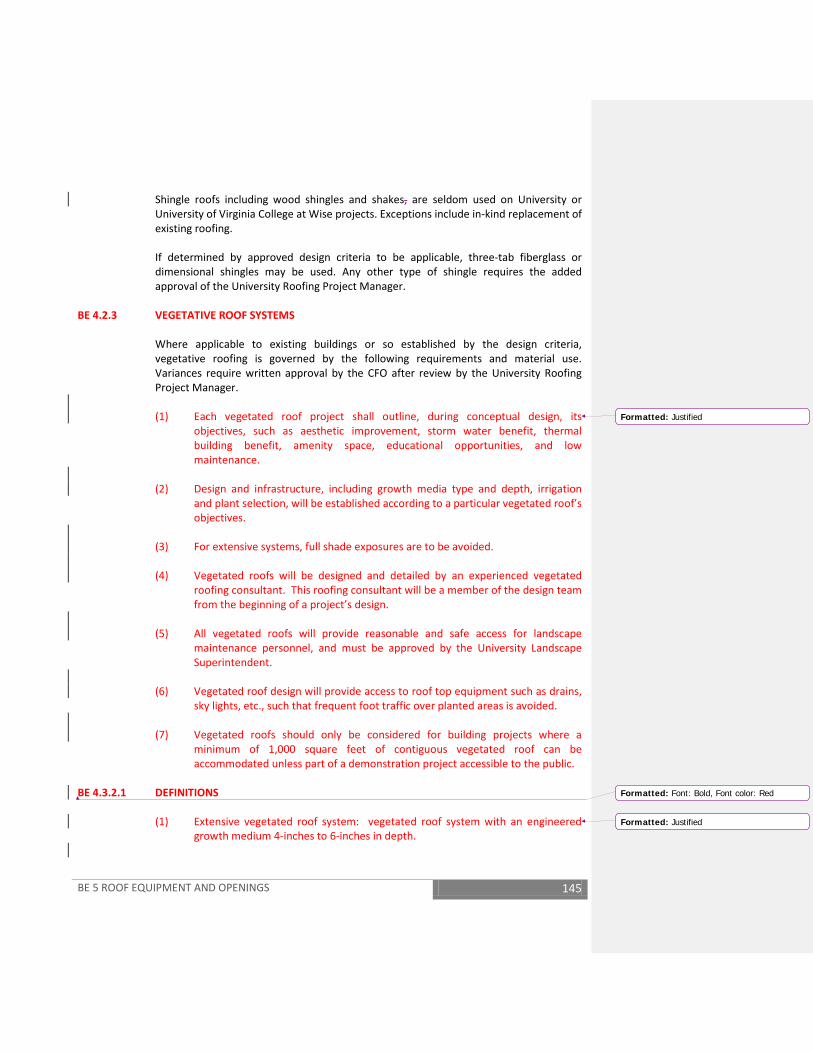
BE 5 ROOF EQUIPMENT AND OPENINGS 145
Shingle roofs including wood shingles and shakes, are seldom used on University or University of Virginia College at Wise projects. Exceptions include in-kind replacement of existing roofing.
If determined by approved design criteria to be applicable, three-tab fiberglass or dimensional shingles may be used. Any other type of shingle requires the added approval of the University Roofing Project Manager.
BE 4.2.3 VEGETATIVE ROOF SYSTEMS
Where applicable to existing buildings or so established by the design criteria, vegetative roofing is governed by the following requirements and material use. Variances require written approval by the CFO after review by the University Roofing Project Manager.
(1) Each vegetated roof project shall outline, during conceptual design, its
objectives, such as aesthetic improvement, storm water benefit, thermal building benefit, amenity space, educational opportunities, and low maintenance.
(2) Design and infrastructure, including growth media type and depth, irrigation
and plant selection, will be established according to a particular vegetated roof’s objectives.
(3) For extensive systems, full shade exposures are to be avoided. (4) Vegetated roofs will be designed and detailed by an experienced vegetated
roofing consultant. This roofing consultant will be a member of the design team from the beginning of a project’s design.
(5) All vegetated roofs will provide reasonable and safe access for landscape
maintenance personnel, and must be approved by the University Landscape Superintendent.
(6) Vegetated roof design will provide access to roof top equipment such as drains,
sky lights, etc., such that frequent foot traffic over planted areas is avoided. (7) Vegetated roofs should only be considered for building projects where a
minimum of 1,000 square feet of contiguous vegetated roof can be accommodated unless part of a demonstration project accessible to the public.
BE 4.3.2.1 DEFINITIONS
(1) Extensive vegetated roof system: vegetated roof system with an engineered growth medium 4-inches to 6-inches in depth.
Formatted: Justified
Formatted: Font: Bold, Font color: Red
Formatted: Justified
BE 5 ROOF EQUIPMENT AND OPENINGS 146
(2) Semi-intensive roof system: vegetated roof system with an engineered growth medium 6-inches to 10-inches in depth.
(3) Intensive roof system: vegetated roof system with an engineered growth
medium greater than 10-inches in depth. BE 4.3.2.2 ACCEPTABLE VEGETATED ROOF SYSTEM TYPES
(1) Modular tray extensive – 1-foot by 2-feet, with interlocking capability, depth to support a minimum of 4-inches of engineered growth media, made from recycled content, with positive drainage cells, and designed such that growth media covers tray edges by 1-inch depth. Trays shall be pre-grown for 1 growing season minimum. Trays set on slip sheet/root barrier of 45-60 mil with bonded seams; material compatible with roofing membrane system. Exposed tray edges to be protected with sturdy, aluminum “L” shaped edging, 4.5-inches by 3-inches, plus or minus.
(2) Integral vegetated roof designed as a comprehensive assembly including fully-
adhered waterproofing membrane, protection course/root barrier, moisture resistant insulation and aeration layer, drainage/water retention elements, filter fabric, engineered growth medium (4-inch depth minimum) and plants. Elimination of any above layers shall only be granted at the approval of University Roofing Project Manager, Landscape Superintendent, and Landscape Architect.
BE 4.3.2.3 ACCEPTABLE WATER-PROOFING MEMBRANE TYPES FOR USE WITH VEGETATED ROOFS 1.
(1) Hot fluid applied polymer modified asphalt (minimum 25% recycled content), applied in two layers with nominal 215 mil minimum thickness and fabric reinforcement between layers; ASTM D6622.
(2) Other membrane systems only if acceptable to University Roofing Project
Manager, Code Review Official and University Architect. BE 4.3.2.4 VEGETATED ROOF SYSTEM WARRANTY
(1) Single-source, full assembly green roof system replacement in the event of membrane failure to include membrane plus all overburden, including soil medium and plant replacement required for a minimum of 20 years.
(2) 50% vigorous plant coverage warranty in 1 year and 80% vigorous plant
coverage in 2 years. BE 4.3.2.5 ENGINEERED GROWTH MEDIUM
(1) Design and specify according to depth of medium and types of plants to be used; consult manufacturer or experienced consultant; meet German FLL
Formatted: Font: Bold, Font color: Red
Formatted: Justified
Formatted: Font: Bold, Font color: Red
Formatted: Justified, No bullets or numbering
Formatted: Justified
Formatted: Font: Bold, Font color: Red
Formatted: Justified
Formatted: Font: Bold, Font color: Red
BE 5 ROOF EQUIPMENT AND OPENINGS 147
requirements for engineered growth medium and submit certified laboratory tests for approval.
(2) Extensive, typical range: 60-100% expanded slate or clay; 0-35% course sand; 0-
25% organic material (compost). (3) Intensive, typical range: 35-60% expanded slate or clay; 25-50% course sand; 5-
20% organic material (compost). BE 4.3.2.6 LEAK DETECTION
(1) Provide electric field vector mapping leak detection systems, where required by the University Roofing Project Manager and Facilities Management for vegetative roof systems.
(2) Components of vegetated roof system, including membrane, must be
compatible with electric field vector mapping leak detection system. BE 4.3.2.7 PLANT SELECTION
(1) Extensive: primarily sedum of mixed variety and with a majority of sedums displaying year-round interest. Select species for shade tolerance where appropriate given roof’s exposure. Sedum installed as plugs, 2 1/4-inch pots or blanket reinforced with biodegradable netting. Species and sizes to be approved by the University Landscape Architect and Landscape Superintendent.
(2) Semi-intensive: sod turf grass and low-maintenance grasses and perennials
adapted to green roof engineered growth medium. Minimum plant installation size 4-inch container; 1 gallon recommended for woody plants.
(3) Intensive: Shrubs, trees and ground covers adapted to roof microclimates and
green roof engineered growth medium; typical landscape installation sizes. BE 4.3.2.8 IRRIGATION
(1) Intensive or semi-intensive vegetated roofs will have sub-surface automatic drip systems with moisture sensor controls.
(2) Extensive vegetated roofs will have, as a minimum, a hose-bib provided for
irrigation during establishment and dry periods. Other temporary forms of irrigation must be acceptable to the University Landscape Superintendent.
(3) Provide permanent irrigation for high-visibility extensive vegetated roofs, type
to be determined and approved by the University Landscape Superintendent. (4) Irrigation shall tap non-potable sources such as condensate or storm water
cisterns.
BE 5 ROOF EQUIPMENT AND OPENINGS 148
(5) Irrigation piping material to be stainless steel or PVC schedule 40. Galvanized and copper piping are not acceptable due to potential leachate damage to plants.
BE 4.3.2.9 INSTALLATION
(1) Installation shall only be done by qualified, certified, experienced vegetated roof installers.
(2) Waterproofing membrane to be water-tested, witnessed, confirmed in writing
and approved by the University prior to installation of any over burden of green roof system components.
(3) Before installing waterproofing membrane, the vegetated roof system
contractor and other appropriate parties shall visually inspect the substrate surface to verify it is clean, dry, smooth and acceptable for vegetated roof membrane and system installation.
(4) Vegetated Roofing Consultant to inspect and approve installation of vegetated
roof system, including all layers, and submit approval to the University Roofing Project Manager.
(5) UV or temperature sensitive roofing materials to be protected prior to and
during vegetated roof installation. (6) Installation will be coordinated by contractor such that trades other than the
vegetated roof installer have limited and managed access to the area receiving the vegetated roof to avoid damage to waterproofing membrane.
(7) Vegetated roofs (accepting pre-grown trays and carpets) shall be planted in
appropriate season. Sedum pots shall be planted March-April-May, or in fall if acceptable to the University Landscape Superintendent. Pre-grown trays and carpets cannot be installed in freezing temperatures. Sedum carpets must be installed immediately upon arrival at project site.
BE 4.3.2.10 MAINTENANCE
(1) Any fertilizers, chemicals and pesticides must be compatible with roof waterproofing membrane system and in compliance with the University nutrient management plan.
(2) Weeding, especially of woody plants, must be performed 2 to 3 times per year,
minimum. During establishment, vegetation should be inspected weekly for tree seedlings and invasive plants.
(3) Irrigation systems to be checked weekly for proper performance and activated
as necessary for establishment and plant health.

BE 5 ROOF EQUIPMENT AND OPENINGS 149
(4) Follow vegetated roof system and/or plant supplier recommendations for irrigation for establishment.
(5) Engineered growth medium to be laboratory tested yearly for pH, salts and
nutrients, or in the event of poor plant growth. (6) Sedum plantings require a pH range between 6 and 8, growth medium should
be tested yearly for pH range due to acid rain, and appropriate corrective actions taken.
BE 4.2.4 STEEL ROOF DECK
(1) Corrosion protection is critical to maintain the structural integrity of the roof
deck from moisture leaks through the roofing membrane. NRCA Bulletin 15-91 provides guidance on protection.
(2) The steel roof deck is required to be Factory Galvanized, G-60 or G-90 (ASTM
A924-94) or Factory coating with aluminum zinc alloy (ASTM A792). (3) ‘Primer paint’ coated deck is not allowed on University projects.
BE 4.2.5 BLOCKING AND MISCELLANEOUS CARPENTRY
(1) Oriented strand board (OSB) or particleboard shall be permitted only with specific approval by the University Roofing Project Manager.
(2) All wood blocking and panel materials shall be pressure preservative treated. (3) Power-driven screw-type fasteners shall be used to fasten wood to wood, or
wood to masonry. BE 4.2.6 UNACCEPTABLE ROOFING SYSTEMS
The following roofing systems are permitted for use at the University only with the specific written project approval by the CFO after review by the University Roofing Project Manager: (1) Ballasted single-ply membranes
(a) Where accepted, minimum requirements include 10-12 pounds of ballast per square foot, double-washed, rounded and smooth river gravel, with a diameter not to exceed 1 1/2-inches.
(b) Ballasted systems are prohibited on any Health System facility, without
exception.
(2) Mechanically fastened single-ply membranes

BE 5 ROOF EQUIPMENT AND OPENINGS 150
(3) Sprayed-on polyurethane foam (4) Modified bitumen systems
(a) Exception: the BUR hybrid system in BE 4.2.1.8 (5) Cold applied roof systems (6) Any roof systems that are torch applied (7) Protected roof membrane (PMR) systems, also referred to as inverted roof
membrane assemblies (IRMA)
(a) Exception: the vegetative roof system in BE 4.2.3 (8) Application of a new roofing system over an existing system; roof-over or re-
cover
BE 4.3 ROOF DRAINAGE, GUTTER AND DOWNSPOUTS
BE 4.3.1 GENERAL
(1) All buildings shall have a positive means of conducting rainwater from the roof
to an underground stormwater system. (2) When an entire flat roof system is being replaced on a roof where there are no
secondary (emergency) roof drains or scuppers, secondary drainage shall be provided as part of the re-roofing project.
BE 4.3.2 ATTACHED GUTTERS
(1) On sloped roofs, adequately sized and securely installed gutters of minimum 16-
gauge copper shall be specified, unless otherwise established by Facilities Management. A minimum slope of 1/16-inch per foot for gutters is required. A minimum of two downspouts for each drain area shall be provided.
BE 4.3.3 BUILT-IN GUTTERS
(1) Built-in or concealed gutters are discouraged for new construction. Where used
specific approval shall be in the established design criteria (see GR 3.5) or so amended design criteria. Built-in metal gutter liner shall be terne-coated stainless steel.
BE 4.3.4 DOWNSPOUTS

BE 5 ROOF EQUIPMENT AND OPENINGS 151
(1) Downspouts of a minimum 16-gauge shall be specified, unless otherwise
established by Facilities Management, and shall be adequately sized and securely fastened to the vertical plane, emptying into a cast iron boot at grade connected to a storm water system. For existing facilities where this is not possible, water will be directed away from the building and new splash blocks will be provided.
(2) Where a building is located near tree, down leader protective baskets shall be
provided to keep leaves away from drain inlets in gutters.
BE 4.4 ROOF SPECIALTIES AND ACCESSORIES
BE 4.4.1 GENERAL (1) Metal flashing, counter flashing, cleats, clips, drip edges, exposed metal
trim/ridge cap, cant strips, scuppers, eyebrow roof vents, and exposed metal valleys shall be:
(a) Terne-coated stainless steel
(b) Copper
(2) Built-in reglets shall be used for all wall-flashing terminations. Surface applied
reglets shall only be used on existing buildings where installation of built-in reglets is not possible.
(3) Solder all non-expansion joints in metal work.
BE 4.4.2 SNOW GUARDS
(1) Snow guards are required for all roofs with a slope of 6 in 12 or greater and over
all entrances regardless of slope. (2) On slate roofs and hand formed standing seam roofs a minimum of three
staggered rows are required. Snow guards shall be copper, stainless steel, or bronze butterfly type.
(3) Wire snow guards are not acceptable. (4) On standing-seam metal roofs, use metal snow rail systems that are attached to
the standing seams. “Butterfly” snow guards mounted on top of the standing seams is not acceptable.
BE 4.4.3 SAFETY TIE-BACK ANCHORS

BE 5 ROOF EQUIPMENT AND OPENINGS 152
(1) Safety tie-back anchors will be installed on all new roofing and reroofing projects. They shall be securely anchored to the building structure and spaced to where all areas of the roof can be accessed.
BE 5 ROOF EQUIPMENT AND OPENINGS
BE 5.1 ROOFTOP EQUIPMENT BE 5.1.1 GENERAL
See GENERAL REQUIREMENTS GR 5.5 Building Systems Access and Equipment.
(1) Abandoned equipment shall be removed and the decking repaired on re-roofing
projects. (2) Where rooftop equipment is utilized the clearance under rooftop equipment
and horizontal supporting members shall be 18-inches for equipment up to 24-inches wide, and 24-inches for equipment over 24-inches in width. Supports shall be mounted and fastened to structural deck or framing, not insulation.
(3) Use of sleepers for rooftop equipment is prohibited. (4) Equipment curbs shall not be placed in drainage valleys. Crickets shall be
installed on upslope sides of equipment curbs. (5) Roof anchors are to be installed on all new buildings that require windows and
skylights to be washed by suspended scaffolds, boatswain’s chair, rope descent system or other suspended system or other equipment maintenance activities that would be considered a fall hazard when conducted.
BE 5.2 ROOF HATCHES
BE 5.2.1 GENERAL See GENERAL REQUIREMENTS GR 5.5 Building Systems Access and Equipment. (1) Where roof hatches are used, they shall be insulated, lockable, and feature
thermal breaks.
BE 5.3 SKYLIGHT STRUCTURES/CLERESTORY WINDOWS
BE 5 ROOF EQUIPMENT AND OPENINGS 153
BE 5.3.1 GENERAL (1) The use of skylight structures, unit skylights and clerestory windows shall be
approved as part of the schematic or Preliminary Design process. University approvals include the Architect for the University and/or the Director of Facilities Planning and Construction.
(2) When approved, skylights shall have exterior grills or guards to provide fall
protection. (3) Drawings and specifications for skylights or clerestory windows shall indicate
dimensioning, flashing, sealants, gaskets, joints and other quality criteria intended to prevent leaks and minimize maintenance. All skylights shall have a minimum 5" high curb on sloped roofs; 12” on flat roofs.


THIS PAGE INTENTIONALLY LEFT BLANK 155
INT 1 INTERIORS - GENERAL INFORMATION 156
INT 1 INTERIORS –GENERAL INFORMATION INT 1.1 DESIGN CRITERIA
In general, building entrances, lobbies and significant public areas require design input and approval by the Architect for the University, coordinated by the Project Manager. The Architect for the University may designate other building areas to be included. Materials, finishes and colors shall be recommended by the Architect/ Engineer, with the involvement of the Requester and/or Building Committee and, when required, the Architect for the University. Exceptions to criteria found in these Facility Design Guidelines require approval of the CFO premised upon a Determinations and Findings Report coordinated by the Project Manager. As a public university, extravagant and/or higher maintenance interior finishes are discouraged. Areas likely to remain in the same use for ten (10) or more years require durable, lower maintenance finishes.
INT 1.2 FINISH CRITERIA Interior flooring, wall covering and ceilings shall be selected from manufacturer’s standard material selection. Custom material selections are prohibited, irrespective of initial lower costs resulting from significant quantities. Future replacement or matching materials are an unnecessary premium in cost. Custom material selections may be used with prior written approval.

INT 2 INTERIORS - CONSTRUCTION 157
INT 2 INTERIORS - CONSTRUCTION INT 2.1 PARTITIONS
INT 2.1.1 GENERAL
Metal stud or masonry partitions shall be used for all non-bearing partitions. Metal stud minimum thickness for partitioning shall be 20 gauge, 16” on center. Spacing 24” on center may be used only where determined partitions will be minimally loaded (no shelves or cabinets planned or likely). Demountable partitions are prohibited. Accordion folding partitions are prohibited. The Health System may allow accordion folding partitions with prior written approval.
INT 2.1.2 FIRE RATED ASSEMBLIES AND FIRE STOPPING Fire rated assemblies, with approved independent testing agency numbers, shall be indicated on architectural drawings for Preliminary Design and construction documents. The fire rated assembly of fire stopping materials shall be indicated on all construction documents drawing details. The A/E shall notify the Project Manager of non-compliant or omitted fire stopping encountered during renovation field investigations or construction. The A/E shall incorporate into specifications the requirement that the contractor shall notify the Construction Administration Manager, or Inspector, and/or the Project Manager of non-compliant or omitted fire stopping encountered during construction. The intent of this is that such materials shall be installed or replaced in compliance with current building code requirements or code requirements in effect during initial construction.
Specifications shall include requirements for closing all openings in fire rated assemblies at the close of work each day.
INT 2.1.3 MOVEABLE PARTITIONS
The University utilizes established contracts for the design, purchase and installation of moveable (open office) partitions and associated components. The A/E shall review the vendor’s drawings and specifications for coordination and interface with electrical systems and incorporate the system design into the contract documents.
INT 2 INTERIORS - CONSTRUCTION 158
INT 2.1.4 GLAZING Glazing for interior partitions shall have a minimum thickness of 1/4". Glazing in interior partitions which are 7'-0"' or less above the finished floor shall be tempered glass. Cross rails are required in glazed partitions at handrail height. Glass specified to have Underwriter's Laboratory (UL) Listing shall have the label left on the glass. The University will remove the labels after acceptance of the building or renovation.
INT 2.2 INTERIOR DOORS
INT 2.2.1 GENERAL All doors shall have a minimum width of 3'-0" and minimum height of 7"-0". All wood doors shall be five plies, solid core with a minimum thickness of 1¾”. Specifications shall call for lifetime warranty of wood doors. All metal door frames shall be welded construction. Clear glazed vision panels shall be used in all classroom and stair doors. Due to higher maintenance and replacement costs, bi-folding, folding doors or folding grilles are prohibited. Dutch doors are prohibited in the Health System. Hollow core wood doors and plastic laminated doors are prohibited. Pocket doors are prohibited. Door finish standard in the Health System is quarter sawn red oak.
INT 2.2.2 LOCKSETS The University, with the exception of the Housing Division which uses a Best 7-pin system, utilizes a Corbin Great-Great-Great Grand Master 7-pin keying system. Locksets shall accommodate University purchased and installed cylinders and cores. Facilities Management or Housing Division lock shop personnel shall accomplish the procurement, keying and installation of cylinders and cores. Construction cores may be installed by the contractor during construction, but will be removed prior to beneficial occupancy. Locksets shall be extra heavy duty, manufactured by Corbin/Russwin, Best or Yale. All interior locksets shall have lever handles with removable core mortised locks in the Corbin ML2000 series, LWA Design and C-7 Keyway, or similar designs in Best and Yale.

INT 2 INTERIORS - CONSTRUCTION 159
Classroom, lecture hall, teaching laboratory, and laboratory corridor access doors shall be equipped with locksets enabling occupants to readily secure door(s) from within the room. The basis of design for these locksets is Corbin/Russwin model ML2067, apartment function (deadbolt by key outside or by thumb turn inside, inside grip simultaneously retracts latch bolt and deadbolt permitting egress without unlocking door). For classrooms, lecture halls, and assembly rooms requiring more than one exit, electronic locking shall be provided from a University agreed switch location(s) within these spaces, including where occupancy loads or agreed design parameters require panic hardware. All panic hardware devices shall be heavy-duty, grade 1 push bar type capable of accepting a Corbin 7-pin cylinder and core (Best 7-pin cylinder and core in housing projects), through bolted with sex bolts where possible, manufactured by Von Duprin, Corbin/ Russwin, or Sargent. The basis of design for panic hardware is Von Duprin model 9900 (and 9900E where electronic locking is applicable). Associated with electronic locking this basis of design is Corbin/Russwin series ED5202/5602double cylinder exit device. See GENERAL REQUIREMENTS, GR 5.3.7 Electronic Access Controls, for major entrances. Unless exempted by an approved Determinations and Findings Report, exterior doors serving students, faculty, staff and general public are to be card reader controlled. University student, faculty, and staff identification systems are 12 or 24 VDC. Hardware finish shall be Builder’s Hardware Manufacturing Association (BHMA) 630. Push button combination locksets or similar types of security hardware may be authorized where required by program. Such locks, when authorized by the Project Manager, shall have an override keyed to the University’s system. Use of combination door locks requires approval by the Facilities Management Locksmith (Academic facilities), Director of Health Systems Physical Plant (Health Systems facilities), and the University Department of Police. Use of combination locks otherwise is prohibited.
INT 2.2.3 CLOSERS All door closers shall be of the heavy-duty type, of cast iron bodies, and having at least a 10-year warranty. Aluminum bodies are prohibited. Closers shall be mounted to doors with through-bolts. Floor closers are prohibited. The use of concealed overhead closers must be authorized on a project-by-project basis.

INT 2 INTERIORS - CONSTRUCTION 160
INT 2.2.4 STOPS Intermediate steel plates or channel reinforcement shall back knob bumpers mounted on drywall construction. Floor stops are prohibited.
INT 2.2.5 HINGES Doors wider than 3'-0" or which have closers shall have ball bearing hinges. The use of floor pivot hinges is prohibited due to associated maintenance and replacement costs.
INT 2.2.6 Kick Plates
Doors subject to abuse by equipment associated with building function shall have kick plates. Consultation with Health Systems Physical Plant is warranted in patient care facilities.
INT 2.2.7 HEALTH SYSTEM DOOR LOCKING HARDWARE ASSOCIATED WITH ELECTRONIC ACCESS
CONTROL
(1) Single Door without Power Assist Device (a) Electric Strike (Modified Frame)
o Full Mortise Lock and Lever (Corbin-Russwin ML 2000 Series) o Electric Strike (Folger Adams 712-75 Electric Strike)
(b) Electric Lock o Full Mortise Lock with request to exit function (Corbin Russwin ML 200901
ECL) (c) Exit Door: Request to Exit and Panic Bar
o Panic Device with electric latch retraction and request to exit (Von Duprin EL99NL series)
(2) Double Door without Power Assist Device
(a) Electric Mortise Lock o Full Mortise Lock and Vertical Rod Device Combination (Von Duprin EL99
Concealed Vertical Rod) (b) Exit Device with Electric Latch Retraction
o Two Vertical Rod Devices, same direction with no overlapping astragal (Von Duprin EL99 Concealed Vertical Rod)
(3) Double Door with Power Assist Devices
(a) Door Operator action initiated by Card Reader and Wall Plate o Auto opener, sensor, and touchless wall plate (Horton) o Two Vertical Rod Devices, same direction with no overlapping astragal (Von
Duprin EL99 Concealed Vertical Rod) (b) Door Operator action initiated by Card Reader action only
INT 2 INTERIORS - CONSTRUCTION 161
o Auto opener, sensor, and relay for instant and delayed action (Horton) o Two Vertical Rod Devices, same direction with no overlapping astragal (Von
Duprin EL99 Concealed Vertical Rod)
(1) Dual Door (egress both directions) without Power Assist Device (a) Card Reader Unlock
o Concealed Vertical Rod Device on secure side with no overlapping astragal (Von Duprin EL99 Concealed Vertical Rod)
o Concealed Vertical Rod Device to meet requirement for special locking arrangement of non-secure side with no overlapping astragal (Von Duprin Chexit Controlled Exit Device, Board Contains Infinite Delay)
(b) Door Operator action initiated by Card Reader action only o Auto opener, sensor, and relay for instant and delayed action (Horton) o Two Vertical Rod Devices, same direction with no overlapping astragal (Von
Duprin EL99 Concealed Vertical Rod)
(2) Access Control (a) Readers are to be HID R40 for wall mount; HID R10 for mullion mounted
o No substitutions (b) All reader request should be directed to the Manager Clinical Engineering
Services
INT 2.3 INTERIOR SPECIALTIES See GENERAL REQUIREMENTS GR 5.7 Custodial Rooms. See GENERAL REQUIREMENTS GR 5.8 Recycling Space Guidelines. See GENERAL REQUIREMENTS GR 5.9 Building Dedication Plaques.
INT 2.3.1 FIRE EXTINGUISHER CABINETS AND EXTINGUISHERS Fire extinguisher cabinets shall be incorporated into all projects where required by code, sized for the required extinguisher. Specifications shall state the required extinguisher type and size. Extinguishers shall be University provided and installed.
INT 2.3.2 INTERIOR SIGNAGE Interior signage shall be provided by contract or by Facilities Management personnel as directed by the Project Manager. The Project Manager shall provide the A/E, or the Interior Designer/Signage Consultant, the established University interior signage standards. Signage criteria vary depending on location, such as University Academic Grounds, Health Systems (Hospital and Medical School) facilities, University of Virginia College at Wise, Mountain Lake, Blandy Farm, or other. Application of existing standards enables Facilities Management to fabricate and install interior signage during the lifespan of buildings.

INT 2 INTERIORS - CONSTRUCTION 162
Wall mounted directories are required for new buildings, additions and renovated structures (where existing directories are not adaptable).
INT 2.3.3 TOILET AND BATH ACCESSORIES The A/E in consultation with the Project Manager shall consider the established practices of Facilities Operations, Health System Physical Plant, or Student Housing Division in the selection of soap dispensers, paper towel dispensers, and toilet paper holders. The Health System shall have infrared controls that are hard-wired, with battery backup, on all hand washing sinks in public areas and paddle blades on sinks in clinical areas.
INT 2.3.3.1 SOAP DISPENSERS Provide not less than one soap dispenser per two lavatories in each restroom.
INT 2.3.3.2 MIRRORS
Provide a 3 inch minimum width metal shelf above all lavatories not mounted above a countertop, finished to match adjacent accessory trim, and approximately 18 inches in length. The shelf may be integral with mirror. Mirrors shall be specified with a minimum ten-year warranty against silver spoilage.
INT 2.3.3.3 WASTE RECEPTACLES Provide free-standing waste receptacles with a minimum capacity of 32 gallons in all toilets having more than one lavatory. In the Health System free standing waste receptacles are acceptable.
INT 2.3.3.4 TOILET TISSUE DISPENSERS
AE shall specify toilet tissue dispensers to be University-furnished, contractor installed (per Building Services specifications).
INT 2.3.3.5 SANITARY NAPKINS
The University does not provide sanitary napkin dispensers. Sanitary napkin disposals shall be provided in all women’s toilet stalls.
INT 2.3.4 TOILET PARTITIONS Steel, ASTM A424, Type I, commercial quality overhead braced toilet partitions are required. Alternative materials (stainless steel, plastic laminate, marble and high-density polymer resin) are to be approved through the Project Manager prior to the submission of the Preliminary Design for review.
INT 2 INTERIORS - CONSTRUCTION 163
Excluding accessible stalls, minimum toilet stall dimensions shall be 2' - 11” in clear width and 4’- 11” in clear length. Exposed particleboard or wood toilet partitions are prohibited.
INT 2.3.5 WALL AND CORNER GUARDS Wall and corner guards are required in corridors and other areas where service carts, moveable equipment, hospital patient stretchers or beds, and such similar equipment will typically be used.
INT 2.3.6 CHALKBOARDS Use chalkboards of either 1/4 to 3/8 inch natural slate or laminated porcelain enameled steel with butted panels, except slate chalkboards are prohibited in the Health System All chalkboards will have trim and full width chalk trays, two-inch tack strip with map rails as an integral part of the chalkboard assembly head trim in all classrooms. Include accessories for map rail use.
INT 2.3.7 WARDROBES, LOCKERS AND COAT CLOSETS The University Housing Division provides manufactured wood wardrobes for student housing rooms.
The A/E shall determine with the Project Manager, when applicable, the responsibilities of the contractor to be incorporated in the construction documents. This may include assignment of the contract or coordination of the installation by others. Provide coat racks, hat racks or hooks in all classroom, office and clinical facility buildings, including provisions for accessibility by physically disabled persons, which shall be provided on toilet stall doors in the Health System
INT 2.3.8 CUBICLE CURTAINS
University of Virginia Health Sciences Center may utilize separate contract(s) for purchasing cubicle curtains. The A/E must incorporate the products from the selected vendor(s) into the project design. The A/E shall determine, with the Project Manager, the responsibilities of the contractor to be incorporated in the construction documents. This may include assignment of the contract or coordination of the installation by others. The track for the cubicle curtains shall be laid out and installed to allow for appropriate clinical activity when the curtain is closed.
INT 3 INTERIORS-STAIRWAYS 164
INT 3 INTERIORS - STAIRWAYS
See BUILDING SERVICES BSRV 5.3.3 Standpipe and Hose Systems.
INT 3.1 TREAD AND RISER CONSTRUCTION All stairs that are not a means of egress shall be constructed to the same criteria as a means of egress stair.
INT 4 INTERIOR FINISHES 165
INT 4 INTERIOR FINISHES
INT 4.1 WALL FINISHES
INT 4.1.1 GYPSUM BOARD The minimum single layer thickness shall be 5/8-inch for walls.
INT 4.1.2 PAINT SELECTION AND COLOR Paint finishes for walls shall be satin, except for the Health System which shall be egg shell. Trim finish shall be semigloss. Other paint finishes require documented University approval through the Project Manager. Paint selections are to be made during the design process. Health System paint colors shall be one of the approved colors, any variance requires prior written approval. To insure economical repainting in the future, all interior classroom, office, corridor or other routine working spaces shall be painted with off white colors. While Facilities Management does not stock premixed paint, the Project Manager will provide representative off white colors intended to permit renovation painting with two, or less, coats.
INT 4.1.3 WALL COVERINGS Wall coverings with textures capable of harboring dirt and/or organic contamination are prohibited in Health Systems (patient care) facilities. Additional materials are to be turned over to Facilities Management through the Construction Administration Manager, specify five percent quantities, in whole rolls, of wall covering materials for each project in which they are used. Where vinyl coated wall coverings are used, the following weights are minimum requirements: (1) Light weight wall coverings (12 to 16 oz per square yard) in areas of light traffic or
areas which are normally out of reach, where it replaces paint to eliminate maintenance.
(2) Medium weight (14 to 20 oz. per square yard) for areas with average traffic (offices, reception areas, hospital rooms and dining rooms).
(3) Heavy weight (24 to 32 oz per square yard) for areas (corridors, classrooms, gymnasiums and service areas) where there is heavy traffic and hard wear and tear.
Where intended to match existing wall coverings, the extent of demolition and installation shall be clearly shown in the plans and specifications.

INT 4 INTERIOR FINISHES 166
INT 4.2 FLOOR FINISHES
INT 4.2.1 CONCRETE FLOOR All exposed concrete floors shall be sealed.
INT 4.2.2 CERAMIC TILE Ceramic tile floor and base shall be used in restrooms and showers; with non-slip floor surfacing. Detailing shall minimize moisture penetration to concrete substrate.
Cement backer board shall be used in all metal stud partition systems. Detailing shall minimize moisture penetration to substrate and/or metal studs. For the Health System, it is suggested for public toilets with more than one fixture, that Stonehard be used with 6”x6” or 2”x4” wall tiles and 12”x12” floor tiles.
INT 4.2.3 QUARRY TILE Quarry tile floor and base shall be used in laundries and food preparation areas and shall have integral non-ferrous non-slip surfacing.
INT 4.2.4 HARDWOOD FLOORING Excluding the Health System, hardwood flooring, excluding athletic flooring, requires Facilities Management approval coordinated by the Project Manager on a project-by-project basis. When used, weather protected entrances shall prevent water damages to hardwood flooring. When approved for use over a concrete slab, a moisture barrier is required. No natural hardwood flooring is allowed in the Health System and natural wood trim may only be used with prior written approval.
INT 4.2.5 RESILIENT FLOORING Resilient tile flooring is prohibited in the Health System. Texas Granite is suggested as an alternative. Noraplan Environcare 3mm product may be used in outpatient areas. Resilient tile flooring shall be 12 inch by 12-inch vinyl composition tile, of homogeneous solid composition, with a minimum thickness of 1/8 inch. Sheet flooring shall be vinyl, of homogeneous though composition, commercially graded flooring, with a minimum thickness of 1/8 inch. The Health System suggests American Biltrite’s rubber flooring. The Facilities Management Building Services Division provides the final floor finishing, except in the Health System where Environmental Services shall provide the final floor
INT 4 INTERIOR FINISHES 167
finishing. Coordinate through the Project Manager regarding requirements to be incorporated into the construction documents.
INT 4.2.6 RESILIENT BASE The standard resilient base in University facilities is a heavy-duty vinyl or rubber base with a minimum thickness of 0.125 inches and a minimum height of 4 inches. For areas subject to heavy-wheeled equipment traffic or frequent maintenance buffing equipment, the minimum height shall be 6 inches. Outside corners shall be specified as premolded.
INT 4.2.7 CARPET The use of separate padding under carpet is prohibited except when authorized by Facilities Management. Carpet in the Health System is prohibited in all clinical areas, but may be used in administrative areas with prior written approval from the Health System.
For compliance with building code requirements and inspection procedures of the State Fire Marshal, specify that contractor shall provide, at the time of inspection, a test report by an approved agency indicating the specific manufacturer’s carpet meets critical radiant flux limitations, the shipping papers for the installed carpet, and a signed confirmation by the manufacturer that the carpet installed matches that tested.
INT 4.3 CEILING FINISHES
INT 4.3.1 GENERAL Access to all utilities above the ceiling shall be provided regardless of ceiling type used. Access panels shall be shown on the contract documents. The A/E shall provide clear requirements in the plans and specifications for the proper reinforcement and support of lighting fixtures and access panels in finished ceilings.
INT 4.3.2 SUSPENDED ACOUSTICAL TILE The use of fire rated ceiling/floor assemblies requiring hold-down clips is prohibited unless there is no other reasonable, economical solution to achieve the required assembly rating. The use of 2’ x 2’ acoustical tile systems is discouraged in areas where not essential for architectural appearance, such as in storage rooms and other rooms not subject to general public use, with the exception of the Health System. Use of 2’ x 2’ ceiling grid should not be presumed without consideration of less expensive systems including light fixture selections.
INT 4 INTERIOR FINISHES 168
When using 2’ x 2’ acoustical tile systems in the Health System they should match the exiting tiles in the area. These systems may be used in any area of the Health System. Armstrong is the suggested provider in the Health System. Large interlocking tiles, such as Armstrong Vector, require prior written approval.

THIS PAGE INTENTIONALLY LEFT BLANK 169
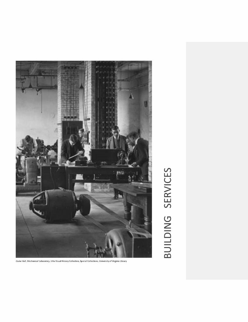

THIS PAGE INTENTIONALLY LEFT BLANK 171

BSRV 1 BUILDING SERVICES GENERAL 172
BSRV 1 BUILDING SERVICES GENERAL
BSRV 1.1 INTRODUCTION Heating ventilation and air conditioning (HVAC) equipment, electrical systems, elevator systems, and building equipment, such as kitchen equipment, associated with new construction and renovations add to energy costs throughout the life of a building; therefore shall be as efficient as possible. Based on the Governor’s Executive Order #82, EPA ENERGY STAR equipment shall be provided whenever available. This is to include HVAC equipment, electrical motors, refrigeration and food service equipment, and other energy consuming equipment operating continuously or for an extended period of time. In addition, University buildings shall be designed for at least a 40 year life with minimum life cycle cost rather than low first cost.
BSRV 1.2 CONNECTIONS TO MECHANICAL, PLUMBING, ELECTRICAL AND CIVIL UTILITIES All utilities to a proposed building site are to be furnished from University central distribution systems, unless either unavailable or demonstrated to be impractical in terms of design or cost. Facilities Management may determine that systems designs shall accommodate development of new or future central distribution systems subject to available funds or potential supplemental funds. Utilities not available or impractical from central distribution systems must be generated at the proposed building. Specifications shall include requirements that alterations or connections to any University domestic water, steam, hot water, chilled water, sanitary, storm, electrical, plumbing, fire protection, gas, compressed air, vacuum, medical gases, energy management systems, and exterior utilities, both distribution and internal, shall be coordinated with Facilities Management Energy & Utilities Department through the Project Manager. For systems serving a building area greater than a renovation project area, or affecting other occupied facilities, specifications shall require that Facilities Operations (Health System Physical Plant for the Health System) be notified through the Construction Administration Manager not less than ten working days before such systems may be affected. See GENERAL REQUIREMENTS GR 10.11 Utility and Building System Outages. Spaces designated as unfinished in new construction shall have plumbing, HVAC and electrical utilities stubbed into them so that when they are finished in the future no demolition is required in the space and outside of it to provide utilities.
BSRV 1 BUILDING SERVICES GENERAL 173
BSRV 1.3 METERING UTILITIES
All utilities shall be metered and shall be connected to building automation systems to be monitored and totaled at the Systems Control Center. All buildings shall be metered individually. The building utility revenue meter shall measure utility demand and totalize the consumption with readings visible on local display. Revenue meters for domestic water, chilled water, heating hot water and steam shall be Owner Furnished, Contractor Installed (OFCI) unless directed otherwise by Facilities Management Energy & Utilities Department. The A/E shall specify the installation requirements for the meters. Refer to individual sections for specific requirements. Outputs from all revenue meters shall be included on the DDC points list, using a convention established by the Energy and Utilities Metering Department.
All meters shall be installed per the manufacturer’s instructions. Revenue meters shall be installed by a manufacturer’s trained and authorized representative.
Unobstructed pipe runs shall be adequate straight pipe, without tees or any other fittings or valves, upstream and downstream of flow meters.
Taps shall be provided to measure flow rate (GPM) at each pump and at each heat exchanger, however, circuit setters shall not be used on variable volume systems. Wells for thermometers shall be provided before and after each heat exchanger.
All meters shall be installed and operational prior to connection of utilities. The operation and calibration of all meters shall be verified, and corrected, if necessary, within 10 working days of connection to utilities. See BSRV 3.1.2 Domestic Water Metering. See BSRV 4.1.5 Meters, Gauges, Indicators & Thermostats. See BSRV 6.2.4 Electricity Metering. See BSRV 7 Electronic Monitoring and Controls. See Appendix C - Utility Metering Requirements.
BSRV 1.4 AESTHETIC CONCERNS All mechanical and electrical equipment and utilities shall be concealed, both on the interior and exterior of buildings, except in mechanical rooms and in laboratories that do not have suspended ceilings.
BSRV 1.5 IDENTIFICATION

BSRV 1 BUILDING SERVICES GENERAL 174
See BUILDING SERVICES BSRV 3 Plumbing, BSRV 4 HVAC, BSRV 5 Fire Protection and BSRV 6.2.1 Interior Electrical Systems, for identification requirements.
BSRV 1.6 HAZARDOUS MATERIALS AND FUME HOODS See BUILDING SERVICES BSRV 4.4.7 Fume Hoods & Lab Exhaust and GENERAL REQUIREMENTS GR 3.14 Office of Environmental Health and Safety.
BSRV 1.7 SOUND PRESSURE LEVEL REQUIREMENTS Sound pressure levels around exterior mechanical and electrical equipment shall not exceed the limits set forth in the City of Charlottesville or Albemarle County Noise Ordinance, or the dbA/time limitations set forth in the Occupational Noise Exposure/Hearing Conservation Amendment latest edition. The Project Manager shall direct questions regarding noise generating equipment and processes or spaces requiring extraordinary attenuation (taping rooms, audiometric exam rooms, etc.) to the University’s Office of Environmental Health and Safety. When placing noise-generating equipment, the A/E shall consider uses of surrounding spaces that may dictate sound levels lower than those specified above. HVAC systems noise levels shall meet Room Criteria (RC) noise levels specified as per ASHRAE 2011 (or most recent) HVAC Applications Handbook, Chapter 48 Noise and Vibration Control.
BSRV 1.8 VIBRATION AND SOUND ISOLATION REQUIREMENTS Walls and floors enclosing mechanical rooms adjacent to occupied spaces shall have a sound attenuation factor of 10 decibels or greater, above the determined or probable airborne noise level of the operating equipment. In no such applications shall the rating be less than a 55-decibel STC. See BUIDLING SERVICES BSRV 4.2.4 Vibration & Sound Isolation Requirements.
BSRV 1.9 CUSTODIAL ROOMS Valves, electric panels or equipment, thermostats, terminal boards for telephone, data or other low voltage equipment, etc. shall not be placed in custodial rooms. See GENERAL REQUIREMENTS GR 5.7 Custodial Rooms for other requirements.
BSRV 1.10 OPERATIONS AND MAINTENANCE MANUALS See GENERAL REQUIREMENTS GR 11.4 Spare Parts and Maintenance Materials.
BSRV 1 BUILDING SERVICES GENERAL 175
BSRV 1.11 COMMISSIONING
All mechanical, plumbing, electrical and fire protection systems shall be commissioned per the below requirements. Facilities Management, or its agent, shall be the Commissioning Authority. The A/E shall include in the specifications the commissioning procedures, requirements and schedules from the Schematic Design phase through the University’s acceptance of the project. The procedures shall meet the University’s commissioning requirements.
BSRV 1.11.1 DESIGN PHASE During pre-design, schematic and Preliminary Design phases, develop mechanical and electrical systems design criteria in consultation with Facilities Management personnel responsible for the operation and maintenance of buildings systems. Such personnel shall include representatives of Energy and Utilities/Systems Control, Operations (Health Systems Physical Plant for Health System), and corresponding Facilities Management Review Unit professional disciplines.
Unless established on a project basis, there are no special commissioning requirements beyond the design and review requirements of HECOM or Chapter 8 of the Commonwealth of Virginia Construction and Professional Services Manual. Specify airflow measuring requirements where applicable under BSRV 1.11.2 below.
BSRV 1.11.2 SUBMITTAL REVIEW AND CONSTRUCTION PHASES A pre-installation meeting shall be held to review coordination drawings and submittals. Mechanical pre-installation meeting shall include all Division 15 and Division 17 trades. See GENERAL REQUIREMENTS GR 10.16 Pre-Installation Conferences. For renovation projects where ductwork is modified, the A/E shall identify any location(s) for the contractor to measure airflow(s) prior to any demolition. The contractor shall be required to report the identified airflow(s) before commencing any HVAC demolition. The intent of this requirement is to identify existing capacities that may be critical to achieve design and/or code requirements. Verify that submittals for all cooling coils specify a return water temperature of at least 62 degrees F. During construction special attention shall be given to items that cannot be easily corrected after construction completion. This includes, but is not limited to, locations of plumbing cleanouts, adequate maintenance access for equipment, adequate straight pipe up and down stream of flow meters, proper connection to supply and return piping, and code required clearances above and around electrical panels. There are no other special commissioning requirements in this phase.

BSRV 1 BUILDING SERVICES GENERAL 176
BSRV 1.11.3 STARTUP AND CLOSE OUT PHASE
All specified tests will be witnessed by representatives of the appropriate (sub) contractor, equipment manufacturer’s representative, consulting engineer and Facilities Management (including designated personnel from Facilities Planning and Construction, Operations or Health Systems Physical Plant, Energy and Utilities, and the University Building Official). The A/E, through the Project Manager, shall schedule all commissioning activities no less than two (2) weeks in advance. The A/E shall certify and document that all commissioning tests and activities have been successfully completed, and that the HVAC systems are functioning in accordance with the manufacturer’s specifications and the contract documents. Specifications shall stipulate that until commissioning is satisfactorily completed:
(1) No heating, ventilation and air conditioning system will be accepted by the University.
(2) The warranty period on all equipment will begin only after acceptance by the University.
All heating, ventilation and air conditioning systems shall be commissioned per the following requirements prior to training University’s operations and maintenance personnel: (1) Point-To-Point (PTP) tests will be performed on all sensors and outputs prior to
testing and balancing and Functional Performance Tests. All damper linkages will be run through their full travel as part of PTP testing. All remote duct and hydronic sensors shall be located and tested. All PTP tests on zone controls shall be done before ceiling tiles are installed. Graphics, alarms, trends, etc. on the University Systems Control computers shall be verified.
(2) All motors shall be checked for proper lubrication, drive rotation and belt tension.
(3) Functional Performance Tests shall be done on all freezestat controls with fan switch in automatic, hand, and bypass position. Functional Performance Testing shall be as stated in HECOM or section 816.0 of the Commonwealth of Virginia Construction and Professional Services Manual (CPSM).
(4) In vivarium, laboratories with high safety levels, and other spaces as specified, differential airflows and proper pressurization shall be verified.
(5) Witness tests shall be performed on all devices that require maintenance including but not limited to, filters, dampers and motors, control valves and motors, reheat coils, and condensate drain pans and traps.
BSRV 1 BUILDING SERVICES GENERAL 177
(6) Furred in or enclosed equipment shall be inspected before being concealed. All information required for record documents and O&M manuals shall be verified.
(7) Cooling coil condensate drain pans and traps shall be checked for proper drainage. In all air handling units and all fan coil units above ceilings pour a sufficient quantity of water into the drain pan to verify proper drainage.
(8) Sound levels of all exterior fans shall be measured and shall comply with the City of Charlottesville or Albemarle County Noise Ordinance.
(9) Chemical fume hoods shall be field tested per the requirements referenced in BSRV 4.X below.
Plumbing systems shall be commissioned as follows:
o Back flow preventers shall be checked for code compliance and a certification report shall be submitted to the Project Manager. Plumbing cleanouts shall be checked for required maintenance access.
o All emergency safety equipment shall be tested and checked for code compliance and a certification sheet shall be submitted to the Project Manager.
o Domestic hot water temperatures shall be verified. Discharge temperature of thermostatically controlled mixing valves shall be verified at minimum flow.
o Unoccupied shutoff of domestic hot water recirculation pumps shall be verified.
o Faucets and showerheads shall be checked to verify that hot water is available within 15 seconds during normal operating hours.
o Plumbing fixture water flow rates shall be verified. Plumbing fixtures shall be considered deficient if they exceed the scheduled water flow rate. Showerheads shall be considered deficient if they are not within plus or minus 25% of the scheduled water flow rate.
Electrical systems shall be commissioned as follows:
o Functional operation of interior lighting, exterior lighting and daylighting control systems shall be verified. This includes the operation of ambient light sensors, dimmers, programmable controllers, photocell controllers, occupancy sensors, bi-level controllers and time clocks.
o Functional operation of occupancy sensors shall be verified. It shall be verified that
occupancy sensors are set to Manual ON, Auto OFF in spaces with exterior glazing and that occupancy sensors are set to Auto ON, Auto OFF in all other spaces.
o Functional operation of lighting time-of day schedules shall be verified.
BSRV 1 BUILDING SERVICES GENERAL 178
o Functional operation of after-hours control devices in public and semi-private spaces shall be verified.
Renewable Energy systems shall be commissioned as follows:
o Functional operation and rated capacities of renewable energy systems shall be verified. This includes, but is not limited to: solar photovoltaic systems, solar thermal systems, wind power generating systems and solar photovoltaic site lighting.
Fire Protection systems shall be commissioned as follows: o Functional operation will be demonstrated in the presence of responsible State and
Facilities Management fire safety personnel for accessibility to fire dampers, fire dampers, automatic fire suppression systems and alarm systems.
The following shall be completed during the first year of systems operation:
(1) Capacities of HVAC equipment shall be verified during extreme summer and winter conditions.
(2) Total energy consumption of the first year of operation shall be compared to scheduled values and any discrepancies resolved.
(3) Revenue meters shall be setup, programmed, and calibrated by a manufacturer’s trained and authorized representative and witnessed by University Energy & Utilities Department.
(4) Revenue meters shall be recalibrated by a manufacturer’s trained and authorized representative 6 and 12 months after initial balancing.
BSRV 1.12 TRAINING AND DEMONSTRATION OF SYSTEMS
After commissioning is complete, but prior to beneficial occupancy or substantial completion, the contractor shall provide field training for designated Facilities Management personnel who are responsible for the operation and maintenance of HVAC, electrical, emergency safety equipment, and fire protection/detection equipment and systems. Classroom training can be held prior to commissioning. Field training shall include a demonstration of all required maintenance activities and proper operation of all control sequences. The A/E shall schedule all training and demonstration activities no less than two (2) weeks in advance.
BSRV 1.13 CLOSE -OUT See GENERAL REQUIREMENTS GR 11 Project Close-out Requirements.
BSRV 2 VERTICAL TRANSPORTATION 179
BSRV 2 VERTICAL TRANSPORTATION SEE ALSO APPENDIX D
BSRV 2.1 ACCESSIBILITY FOR THE DISABLED In addition to the requirements of ADA, passenger elevators shall provide: (1) Hall call and cab call shall be flush, not raised.
(2) 6" x 8" cutout for emergency telephone, located between 24" and 48" above the cab floor. University to provide and install telephone. Conduit, wiring and all other requirements shall be provided in design and by the contractor to accommodate a Talk-A-Phone ETP-100.
BSRV 2.2 ELEVATORS In addition to the following, A/Es are encouraged to consult with the Elevator Maintenance Supervisor, Facilities Management Operations Department or Health Systems Physical Plant, by arrangement with the Project Manager. Cab door heights over 8’-0” shall be prohibited unless approved by the appropriate elevator maintenance shop. Recommendations may include proven manufacturers to be included in specifications.
BSRV 2.2.1 ELEVATOR MACHINE ROOMS AND PITS
Elevator equipment rooms shall not be used for access to roofs or other parts of the building unless elevator equipment is fenced or walled in. Traction-type elevators shall have machinery located overhead. Written approval of the CFO is required for an under-slung installation. Rope elevators shall not be used. Underground hydraulic piping for elevators shall be schedule 80. The electric fused disconnect switches or circuit breakers for the elevator and cab lights shall be adjacent to the door jamb of the main access door to the machine room. Elevator pits for hydraulic elevators shall have sump pits for use of a portable sump pump by Facilities Management personnel. Drainage from the elevator pit shall not be connected to any building drainage or sewer system. Sump pits shall be equipped with a float sensor connected to Facilities Management Systems Control.
BSRV 2 VERTICAL TRANSPORTATION 180
Health Systems Physical Plant prefers permanent sump pumps for non-hydraulic elevators, subject to environmental requirements for preventing contamination of sanitary or storm water drainage systems.
BSRV 2.2.2 CONTROL SYSTEMS
Elevator controls shall be solid-state “Selective Collective Automatic Operation”, as defined in ASME/ANSI A17.1. Controller shall be non-proprietary and shall not require a battery to maintain programming. Control system shall be microprocessor based for dispatch and motor control, capable of computer based monitoring with terminals for connection
BSRV 2.2.3 DIAGNOSTIC REQUIREMENTS For microprocessor control system, specifications shall require that diagnostic tools, hand held or built into the control systems, be functional for the lifetime of the equipment, without requiring recharging or reprogramming. The use of proprietary equipment shall be prohibited by the specifications.
BSRV 2.2.4 WARRANTY SERVICE REQUIREMENTS The specifications shall be explicit regarding: (1) Contractor shall provide four (4) sets of all electric schematic wiring diagrams,
access codes or passwords required for all maintenance functions. including diagnostics, adjustments and parameter reprogramming. Tools may be hand held or built into the control systems, and shall function for the lifetime of the equipment. Tools that require recharging or reprogramming shall not be used. The successful contractor upon completion of the project shall provide any special tools, prints, and technical operation of equipment that cannot be obtained from multiple suppliers to the University. Specifications shall be explicit that all tools, adjusters, manuals and schematic wiring diagrams become the property of the University to be used at their discretion related to the installed elevator or elevators.
(2) Prior to the end of the warranty period, the Elevator Contractor shall readjust
the elevator as required to meet all performance parameters specified. A written report shall be submitted by the Elevator Contractor to the University Service Contract Manager.
BSRV 2.2.5 FINAL ACCEPTANCE
Include the following statement in all Elevator Specifications: “As a part of final acceptance of the project and in accordance with the Contract General Conditions, the contractor shall have a Qualified Elevator Inspector (QEI) conduct a full Acceptance Inspection and Test in accordance with ASME/ANSI A17.1 before final acceptance by the Owner. The contractor shall obtain from the elevator
BSRV 2 VERTICAL TRANSPORTATION 181
Contractor and/or manufacturer and furnish to the Owner all data affecting the elevator installation or modification, including ‘as-installed’ circuit and control wiring diagrams and maintenance manuals.”
BSRV 2.2.6 ELEVATOR TYPES AND COMPONENTS
Compliance with requirements for non-proprietary components is mandatory and essential to the University for its safe and expedient operation and maintenance of elevators throughout multiple buildings.
BSRV 2.2.7 ELEVATOR CAB SIZE
All new buildings provided with elevator service shall have at least one elevator sized and configured to accommodate an ambulance type stretcher (76 inch x 24 inch) in the horizontal position. See the applicable VUSBC sections on elevators and conveying systems for additional requirements. Where existing elevators are being replaced, the above criteria shall be met where possible.
BSRV 2.2.8 AUTOMATIC POWER DISCONNECTION
In order to prevent people from being trapped in an elevator when power is automatically disconnected in accord with the requirements of ASME/ANSI A17.1, the policy below shall be applicable for all new and remodeled University building elevator systems.
Provide controls necessary to accomplish the following: (1) Heat detectors required by Rule 102.2 (c) (4) shall provide a signal to initiate
Phase I Fireman's Service Emergency Recall Operation Rule 211.3a. The activation sequence shall be similar to requirements for smoke detectors in Rule 211.3b. No additional heat detectors are required other than those called for by Rule 102.2(c) (4).
(2) Provide an elevator travel time delay, equivalent to the elapsed time for an
elevator to travel from its farthest stop to the designated recall level plus ten (10) seconds before power to the elevator equipment is disconnected and pre-action sprinkler is activated as required by Rule 102.2(c)(4). [Elevator Travel Time Delay = the time for an elevator to close its doors, under Phase I conditions, return to the designated recall level, and open its doors. If there are multiple elevators, the elevator having the greatest travel time shall be used in determining the time delay.] See Sample Circuitry Diagram in Figure 20.
BSRV 2 VERTICAL TRANSPORTATION 182
BSRV 2.3 OTHER VERTICAL TRANSPORTATION
BSRV 2.3.1 DUMBWAITERS
Dumbwaiters require documented justification by the user and Architect/ Engineer, and subsequent approval by Facilities Planning and Construction. If approved for use, a car safety gate shall be provided to prevent loads from falling while the car is in motion. Controls shall not allow movement unless the door is closed. A "door open" signal shall be provided. If provided for three or more landings, "in-use" indicator lights shall be provided.

BSRV 3 PLUMBING 183
BSRV 3 PLUMBING
BSRV 3.1 DOMESTIC WATER
BSRV 3.1.1 WATER SUPPLY AND TREATMENT Domestic water is obtained from the University distribution system. New service lines shall be valved at the point of connection to the main and at entry to the building. Pressure reducing valves shall be provided in all buildings at the domestic water entrance just downstream of the meter. Provide a full size bypass loop around the PRV and meter. Provide a strainer with blow down valve upstream of the meter bypass loop. Provide a backflow preventer (BFP) downstream of the meter bypass loop, with a bypass BFP that can accommodate full flow conditions. Provide isolation valves so either BFP can be removed. Water line shall be disinfected and tested for bacteria. Vacuum breakers used for mop sinks and food service shall be pressure type in accordance with ASSE 1020.
See SITEWORK SW 5.3 Exterior Domestic Water and Chilled Water Piping for requirements also applicable to exterior domestic water piping. The use of domestic water for process cooling is prohibited.
BSRV 3.1.2 DOMESTIC WATER METERING Meters shall be installed at each building, constructed of materials suitable for domestic water, shall be capable of showing cumulative gallons and of measuring the maximum and minimum anticipated flow rates. Meters for domestic water shall be revenue grade having a maximum inaccuracy of 1% of rate and span. Boiler, chiller and cooling tower make-up and blow down shall be metered separately. Irrigation systems shall be metered separately. Fire protection service shall not be through the domestic metered water system. See BSRV 7 Electronic Monitoring and Controls, for additional requirements. See Appendix C - Utility Metering Requirements.
BSRV 3 PLUMBING 184
BSRV 3.1.3 DOMESTIC HOT WATER Use chemical sterilization and/or booster heater systems for dishwashing needs instead of higher temperature supply hot water. Provide temperature control devices for domestic water heaters. Domestic hot water storage systems and domestic hot water recirculation pumps shall have an input from the BAS so they can be turned back or off during scheduled unoccupied times. Consider instantaneous units for heating domestic hot water. Medium temperature hot water (MTHW), high temperature hot water (HTHW) or steam shall be used to generate domestic hot water, except where centrally generated domestic hot water is available or where loads are very small. Instantaneous heaters shall be used for all domestic hot water loads. Hot water storage tanks shall not be used. Domestic hot water recirculating pumps shall automatically be turned off during unoccupied hours. Parts of the University Health Systems facilities receive domestic hot water at 140 degrees Fahrenheit. It is generated by the Central Heating Plant and delivered over a distribution system. Contact Facilities Management Energy and Utilities or Health Systems Physical Plant for specific locations served.
BSRV 3.2 MATERIALS The selection of materials by the A/E shall be subject to approvals coordinated by the Project Manager. All domestic water piping inside buildings shall be type L hard drawn copper with soldered joints
Supports and other metal parts subject to use shall be galvanized. Shut off valves are required at the main service entrance into buildings, on each floor, on take-offs from all vertical risers, and at the connection to each piece of equipment. Domestic water pipe shall not be installed in or under concrete slabs on grade, except where necessitated by building entrances or under sidewalks. All piping systems shall be hydrostatically tested after installation. The test pressure shall be 200 psi or 1 1/2 times the working pressure, whichever is greater. Components

BSRV 3 PLUMBING 185
that are not suitable for a 200 psig test may be tested at a lower pressure and then valved off for the 200 psig test. Test duration shall be at least 2 hours. Maximum water use rates for showerheads, faucets, water closets and urinals shall meet the requirements of the VUSBC. Urinals shall be 0.125 gpf (1 pint) type. Water closets shall be 1.28 gpf or dual flush type where appropriate.
BSRV 3.2.1 IDENTIFICATION All piping and equipment in mechanical equipment rooms and central plants shall be completely painted according to the “Scheme for the Identification of Piping Systems”, ANSI A13.1 and the “Safety Code Color for Marking Physical Hazards”, ANSI Z53.1, latest revisions. All piping in buildings shall be identified by means of alphabetical stencils and color codes, showing contents of the piping and the direction of flow. Piping shall be identified at 30’ intervals, on both sides of penetrations through walls and floors, and at each directional change. All valves shall also be identified with stamped brass tags or discs secured with non-ferrous beaded chain. Valve numbers shall be engraved or stamped as large as possible on tags (1 inch by 2 inches) or discs (1.25 inch diameter) attached to the valves by 10-gauge brass "s" hooks. Provide a framed valve schedule in mechanical rooms.
BSRV 3.3 WATER DISTRIBUTION Insulation on domestic water lines shall be continuous through floors, walls and studs. Closed water piping systems shall have air vents to purge any trapped air. Valves shall be compatible with the piping materials. Valves shall have valve tags, appropriate identification and valve sheets. Non-ferrous ball valves up to 4” can be used on domestic water. Non-ferrous or ductile iron butterfly valves can be used on 2 ½” and above. Gate valves shall not be used except where provided with backflow prevention devices.
Dielectric fittings or 6” long brass nipples shall be used when connecting piping of dissimilar metals. Drain valves shall be installed in accessible locations at all low points in the piping system to permit drainage and servicing. When plumbing fixtures are removed but not replaced, domestic water pipes shall be removed to within five (5) pipe diameters of the main to prevent leaving a long dead

BSRV 3 PLUMBING 186
leg, and terminated with a capped ball valve. Where plumbing fixtures are removed but the water pipes will be reused the pipes shall be capped to prevent debris from entering pipes. Aerators for lavatories in toilets, kitchens and similar use shall be 1.5 gpm maximum. Hose bibbs shall be spaced at a maximum of 100 feet around the entire building.
BSRV 3.4 STORM AND SANITARY WASTE SYSTEMS
The University-owned sanitary sewerage system connects to city-maintained sewerage lines and the Rivanna Water and Sewer Authority's treatment plants. Sanitary cleanouts shall be located with a minimum floor clearance of 15 inches from adjoining walls or built-in features, such as toilet stalls or casework. Unless approved as an exception for servicing vertical risers, cleanouts shall not be located in vertical surfaces. Provide cleanouts on sanitary and storm lines on exterior lines within 5 feet of the building. Provide floor drains below emergency showers. Pumped discharge lines from sewage and storm ejectors shall not be combined with gravity drains inside buildings. Pumped and gravity drains shall run separately to the nearest manhole. All gravity storm and sanitary drains shall be cast iron except for an acid resistant material where justified and for under slab and footing drains. Pumped storm and sanitary lines shall be copper; type L inside the building and type K outside.
BSRV 3.5 SPECIAL PLUMBING SYSTEMS
BSRV 3.5.1 PIPING SYSTEMS FOR GASES Piped gas systems shall be thoroughly identified and coded. Piping of any gases in Health System (Hospital and Medical School) projects will require special coordination with Health Systems Physical Plant. All medical gas outlets shall be D.I.S.S. type. All piping, tubing, and fittings shall be pre-cleaned. Copper shall be type K. Vacuum pumps shall be CLAW or dry rotary vane type; liquid ring vacuum pumps shall not be used. All fuel gas pipe downstream of the meter shall be above grade.
BSRV 3 PLUMBING 187
A shut off valve for natural gas shall be provided at the room entrance or other location approved by Facilities Management. Natural gas outlets shall not be installed in bio-safety cabinets or other contained rooms or areas that are not fully exhausted.
BSRV 3.5.2 EMERGENCY SHOWER AND EYEWASH EQUIPMENT FOR LABORATORIES
Emergency eyewash and shower stations are required in areas where chemical, biological, radiological, or physical hazards including battery charging stations exist that may expose the eyes or body to corrosive, infectious or other injurious materials. The location of emergency irrigation equipment shall be made upon consultation with OEHS and will adhere to applicable regulations and consensus guidelines (e.g. The National Research Council’s /Prudent Practices for Handling Hazardous Chemicals in Laboratories /National Academy Press, most recent edition). The specifications and installation of emergency irrigation equipment shall comply with the latest version of ANSI Standard Z358.1. All spaces where Biosafety Level 2 or Animal Biosafety Level 2 (housing) and above materials are manipulated require an eyewash and a hand wash sink.
Safety showers should be placed in a consistent location throughout the laboratory building and provided with highly visible “Safety Shower” signs to facilitate occupant’s awareness of their location. Showers with pull down bars are preferred over chain pulls. The installation of drains beneath safety showers is preferable. ANSI-approved eyewash facilities shall be provided in at least one sink in each laboratory or work area (i.e., shop areas, mechanical rooms, etc.) if substances used there are known to present a potential eye hazard. The project team should work with OEHS and the customer to ensure that sink functions that will occur in the laboratory do not obscure the presence of the eyewash fountain or obstruct access.

BSRV 4 HEATING, VENTILATION, AND AIR CONDITIONING 188
BSRV 4 HEATING, VENTILATION, AND AIR CONDITIONING
BSRV 4.1 GENERAL
BSRV 4.1.1 DESIGN PARAMETERS (1) Life Cycle Cost
The criteria contained in this section supplements VUSBC to assure minimum standards as indicated and applies to all appropriate projects in the Capital Outlay Program. Its purpose is not to limit architectural and engineering freedom, but to create awareness that all designs must effectively minimize the use of energy and minimize life cycle cost. The development of these standards/guidelines has demonstrated that energy efficient designs provide very significant energy savings and reductions in life cycle costs. Compliance with these standards/guidelines is mandatory. Energy efficiency considerations are a function of building design. All projects financed by the Commonwealth will be evaluated for energy conservation and life cycle costs. Computerized energy budget analysis, forecasting energy consumption in BTU/GSF/year is mandatory for all projects with greater than 8,000 gross square feet which have heating and cooling and with greater than 20,000 gross square feet which have heating only.
(2) Energy Performance The minimum energy performance for all new construction shall be the minimum required for LEED certification but no more than 14% less than the energy use allowed by the currently adopted version of ASHRAE 90.1. Calculations supporting energy performance shall be performed and submitted using the latest version of DOE-2 energy use and cost analysis software; equivalent energy analysis software can only be used with prior approval. For renovations an energy use analysis based on existing conditions shall be performed and benchmarked to historical use as recorded in the Energy and Utilities Department billing database. The maximum allowable fan energy shall be 10% less than the values listed in ASHRAE 90.1. Energy conservation measures that reduce the peak-cooling load (such as heat or energy recovery) with up to a 15-year payback shall be employed. Other energy conservation measures with up to a 10-year payback are acceptable.

BSRV 4 HEATING, VENTILATION, AND AIR CONDITIONING 189
Methods of energy conservation, such as energy recovery from exhaust air shall be evaluated. The method of heat recovery shall not create a potential for cross contamination from noxious exhaust. System shutdown and night setback or reduction of outside airflow shall be provided for all systems to reduce energy use during periods of non-use, except in special laboratory applications. Ventilation rates and total air circulated shall be kept to the minimum as required by VUSBC, ASHRAE Standard 62-1989, or recognized special space requirements. Each mechanical ventilation system (supply and/or exhaust) shall be equipped with a readily accessible means for either shutoff or volume reduction when ventilation is not required, including morning warm-up. Use outdoor air for cooling as defined by the VUSBC. The use of electric resistance as the primary source of heat is not allowed without a waiver from the CFO. If electric resistance heat is the only option for heating, documentation justifying the same shall be submitted to the CFO for approval. Humidification for human comfort will not be allowed. Humidification is not to be provided unless justified by special project criteria. Use hot water temperature reset controls. Size pumps, fans, chillers etc. to design load; do not oversize. Use variable speed drives on VAV fans. Use electric ignition instead of pilots. Provide means to shut-off HVAC distribution to unoccupied areas. Exceptions will be granted to hospitals, health care facilities, and other specialized construction, i.e., labs, computer rooms etc. Avoid the use of constant volume reheat systems. Use primary/secondary pumping and/or variable volume pumping. Avoid supplying simultaneous heating and cooling to a zone. Evaluate thermal storage for electrical demand reduction, if current utility rates justify this technology. Evaluate the potential for co-generation. Evaluate the use of high efficiency, ground coupled, water source (geothermal) heat pumps.

BSRV 4 HEATING, VENTILATION, AND AIR CONDITIONING 190
Spaces that require a continuous and constant supply of outside air shall have a heat recovery system. The system shall be selected for a payback of no more than 10 years. Desiccant-coated heat recovery devices are acceptable and encouraged.
(3) Design Conditions
Design Conditions: Design heating and cooling systems using the following criteria:
(a) Heating - Use the median of annual extremes for outside temperature included in the most recent ASHRAE Handbook Fundamentals data. Use Inside Design Condition Criteria in Figure 21 for inside temperatures.
(b) Cooling - Use two and one-half percent (2-1/2%) figures for outside Wet
Bulb and two and one-half percent (2-1/2%) figures for Dry Bulb temperatures included in Figure 21 or the most recent ASHRAE Handbook Fundamentals data. Use Inside Design Condition Criteria in Figure 21 for inside design temperature.
(c) For any Occupancy/Use not shown in the Inside Design Condition
Criteria, Figure 21, consult ASHRAE Handbooks or other applicable references for suggested criteria and obtain CFO approval of conditions proposed for use in design.
(4) Controls and Systems
The vendor of electronic monitoring and controls shall provide all control devices. See BUILDING SERVICES BSRV 7 Electronic Monitoring and Controls. All controls shall be DDC and all actuation shall be electric. A 5 year warranty shall be specified on electric actuators. During renovations all pneumatics in the area being renovated shall be replaced with DDC and electric actuation. When DDC is used on air handler units (AHU), a laptop computer shelf with a required hook up shall be provided at each AHU, chiller, etc. Individual offices shall have means of ensuring acceptable temperature control (user adjustable thermostat and control device, appropriate zoning or other designed means). Mount supply and return fan VFDs close enough together so the readouts can be seen at the same time without moving.
BSRV 4 HEATING, VENTILATION, AND AIR CONDITIONING 191
Only HEPA filters and filters for critical areas are to have DP sensors tied into the University Energy Management System. Provide Magnahelic or inclined manometer on all other filters. The air tubing on VAV boxes shall be neoprene rather than rubber or plastic.
Controls such as carbon dioxide (CO2) or occupancy sensors shall be used to modulate outside airflow in classrooms and auditoriums, unless demonstrated not to be cost effective. On units with CO2 control, the sequence of operation shall specify when outside air dampers can be closed, and when fans can be shut off.
Units with CO2 controls which serve only classroom(s) will be shut off during unoccupied hours when CO2, temp, and relative humidity are satisfied; and restarted on demand by any of those sensors. An occupancy sensor will also restart AHU. When all classrooms on a given system are empty during normal occupied hours, the outside air damper shall not close but shall go to a minimum position (approximately 1 cfm per “chair”), and the CO2 level will be allowed to drop. If extreme conditions prevent the system from maintaining all set points, the CO2 level will be allowed to drift. The EMS will monitor points as required to detect failure to maintain any set point.
VAV systems that simply reduce outside airflow in proportion to supply airflow shall not be used. Spaces of different uses (such as offices and classrooms) may only be served by the same AHU if CO2 sensors or other approved controls are provided in adequate quantity and location to ensure code required outside air to all spaces.
Untempered outside air shall not be supplied directly to occupied spaces or into the returns of fan coil units. Constant volume systems shall only be used where required by program or where variable volume air control is impractical. Constant volume recirculating systems shall have a means to pre-cool and dehumidify outside air before being mixed with the return air rather than cooling the entire supply airstream to dehumidify and then reheating. A chilled water coil, heat recovery device or other method approved by Facilities Management may be used. Sequence will specify if fans run continuously or can be shut off. Supply, return, and exhaust fans shall be interlocked as required. AHUs should have manual override to run unit with high outside airflow (for venting odors from new carpet/furniture, floods, etc.)
In buildings that do not have other fire/smoke detection, the AHU smoke detectors shall be used to alarm the DDC system. The AHU supply and return fans will run continuously but the outside air dampers shall be closed by occupancy sensors, carbon dioxide controls, or by the EMS during unoccupied mode. If smoke enters an AHU, the fans in that AHU shall stop; however all other fans in the building shall continue to run if allowed by code.
BSRV 4 HEATING, VENTILATION, AND AIR CONDITIONING 192
Where perimeter heat is needed at large windows and exterior walls, it shall be interlocked with AHU/zone control. Perimeter heat will normally be supplied from a closed building LTHW loop with a converter served by the University MTHW system. Freeze protection shall be provided on all air handling units. Freezestats shall stop the supply fan, close the outside damper, and open the heating coil valve, by means of positively venting air from the actuators. Where DDC is used, the freezestat controls shall be completely independent of the DDC system. (5) Identification All piping and equipment in mechanical equipment rooms and central plants shall be completely painted according to the “Scheme for the Identification of Piping Systems”, ANSI A13.1 and the “Safety Code Color for Marking Physical Hazards”, ANSI Z53.1, latest revisions. All piping in buildings shall be identified by means of alphabetical stencils and color codes, showing contents of the piping and the direction of flow. Piping shall be identified at 30’ intervals, on both sides of penetrations through walls and floors, and at each directional change. All valves shall also be identified with stamped brass tags or discs secured with non-ferrous beaded chain. Valve numbers shall be engraved or stamped as large as possible on tags (1 inch by 2 inches) or discs (1.25 inch diameter) attached to the valves by 10-gauge brass "s" hooks. Provide a framed valve schedule in mechanical rooms. All motor driven equipment, HVAC components, and major electrical boxes shall be individually numbered on the drawings by the A/E and have corresponding number plates on the equipment. (Example: For unit heaters, use UH-1, UH-2, etc., even though both units are of the same size and type.) All designations shall be integrated with and distinguished from existing designations. The construction documents shall require the contractor to color identify all equipment using the numbering system shown on the drawings with a color that contrasts with the equipment finish. In finished areas, identification shall be located on the inside surfaces of access doors; in unfinished areas, on outside surfaces. Tags may be used where preferred, and permanently attached.
New equipment containing 50 pounds or more of refrigerant should have a nameplate attached which identifies the manufacturer, model and serial numbers, date of manufacture, type of refrigerant, and maximum quantity (full charge) of refrigerant in the system.
BSRV 4.1.2 CHEMICAL CLEANING & CHEMICAL WATER TREATMENT OF BOILERS & HVAC SYSTEMS
The boilers, the HVAC systems, all system piping, and all system related equipment shall be thoroughly flushed out with pre-cleaning chemicals designed to remove construction related deposits such as pipe dope, oils, loose mill scale, and other extraneous material.

BSRV 4 HEATING, VENTILATION, AND AIR CONDITIONING 193
Systems shall be cleaned and/or boiled-out in accordance with the manufacturer’s instructions and the recommendations of the University’s Water Treatment Consultant. The products used shall inhibit corrosion of the various metals in the system and shall be safe to handle and use. The A/E shall consult with the University and the A/E’s Water Treatment Consultant to determine the proper cleaning and water treatment requirements for boilers, piping, and other HVAC systems. The chemicals to be used by the contractor for the specified initial treatment shall be furnished by Facilities Management and funded by the project. The University shall provide all chemical treatments after systems have been cleaned, flushed, and filled. In individual buildings, only closed loop systems, such as secondary heating water and process water, shall have chemical treatment (chemical treatment for fluids from central systems will be provided at the heating or chiller plant)
The A/E shall specify the standards and requirements applicable to the chemical cleaning and water treatment of the system. The following should be addressed: (1) The standards to be met by the contractor in flushing, cleaning and treating the
system.
(2) That the contractor is responsible for providing all equipment, fittings, tubes, valves, connections, labor, chemicals, and miscellaneous hardware for the boiler boil-out, for the flushing, cleaning and associated water treatment, and for the initial chemical water treatment for the boilers and HVAC systems.
(3) The University provided chemicals to be used for the initial treatment of the system after flushing and cleaning have been completed.
(4) That the chemical formulation used shall be compatible with system materials.
(5) That the chemicals used shall conform to DEQ regulations and requirements.
(6) That the chemical mixtures do not exceed DEQ or local effluent limits.
The A/E must specify that the contractor notify the University approximately 30 days before the boil-out/cleaning of the system and the application of the chemicals are started. The University’s Water Treatment Consultant shall observe and monitor the boil-out/cleaning of the system and the initial charge of chemicals required for placing the equipment in normal service.
BSRV 4 HEATING, VENTILATION, AND AIR CONDITIONING 194
The Construction Documents shall require that after cleaning and chemically treating boilers and HVAC systems, the contractor shall furnish the University, in writing, the following information: (1) Date of initial treatment.
(2) Type of chemical(s) used for treatment.
(3) Estimated date that further treatment or testing will be required.
The University shall continue monitoring and treating the water after initial treatment.
BSRV 4.1.3 DISTRIBUTION Taps shall be provided to measure flow rate (GPM) at each pump and at each heat exchanger, however, circuit setters shall not be used on variable volume systems. Wells for thermometers shall be provided before and after each heat exchanger. Hydronic pipe shall not be installed in or under concrete slabs on grade, except where necessitated by building entrances or under sidewalks. Shut off valves are required at the main service entrance into buildings and on each floor at take-offs from all vertical risers. Dual temperature systems and other configurations that will allow mixing of two or more chemical treatment sources shall not be used. Strainers shall be provided at the inlet to all pumps and loads. All strainers shall be provided with blow down valves. All air handler coils, reheat coils, convectors and fan coil units shall incorporate isolation valves. A flow control device (circuit-setters) with a multi-turn flow-regulating valve shall be provided on constant volume systems, however circuit setters shall not be provided on variable volume systems.
BSRV 4.1.4 TESTING AND BALANCING All HVAC systems shall be tested and balanced in accordance with a standard of a recognized testing laboratory. The greatest adverse influence on air motion near a hood is from the supply air distribution system. It is generally recommended that supply air velocity of 50% of the required hood velocity should be maintained with the occupied space near a hood. All piping shall be tested at 200 psi or 1 1/2 times the design pressure, whichever is the greatest. Test duration shall be at least 2 hours. Pressure tests shall be witnessed by the

BSRV 4 HEATING, VENTILATION, AND AIR CONDITIONING 195
Energy and Utilities Department System Manager, the Maintenance Superintendent or their designees. All welds in high pressure steam, pumped condensate, MTHW and HTHW piping shall be x-rayed from primary to secondary systems. The x-rays of the welds shall satisfy ASME B-31.1. In steam PRV stations, the pipe up to the shut off valves downstream of the first stage PRV’s shall be pressure tested and x-rayed per the requirements of HPS. Testing and balancing of building chilled and hot water distribution pumps shall use the revenue meters and not the DP across pumps. A portable meter with less than 1% error shall be used on branches which do not have full flow; a suitable meter can be borrowed from the University if available.
BSRV 4.1.5 METERS, GAUGES, INDICATORS AND THERMOSTATS
Meters shall be installed at each building on each utility and shall be capable of showing cumulative energy demand and of measuring the maximum and minimum anticipated flow rates. All revenue meters shall have diagnostics. The outputs from all revenue meters shall be included on the DDC points list, using a convention established by the Energy and Utilities Metering Department. Provide adequate straight pipe, without tees or any other fittings, up and down stream of flow meter. See BSRV 7 - Electronic Monitoring and Controls. See Appendix C - Utility Metering Requirements. Gauges shall be specified on supply/return of pumps, chillers, converters, and where lines enter and exit mechanical rooms. Thermometers shall be specified on supply/return water chillers, air-handling units, fan coil units, and at other points. Where non-digital readout gauges are used, the following shall apply: (1) Gauges for general use shall have screw-type recalibration, bronze bushed
movements and single unit construction.
(2) In main mechanical rooms, provide 4.5 inch diameter gauges for all steam pressures, and mounted a maximum of 8’-0” above the operating floor.
(3) Gauges shall be calibrated for static head.
BSRV 4 HEATING, VENTILATION, AND AIR CONDITIONING 196
(4) All gauges shall be non-pulsating.
Temperature gauges are acceptable where mercury thermometers would be difficult to read. Gauges and thermometers shall read to twice the operating pressure or temperature.
BSRV 4.1.6 CONTROL AIR
Where pneumatic controls are approved, the A/E will confirm the existence, and capacity, of a central source of compressed air within the University building or, if required, provide a source or additional capacity.
BSRV 4.1.7 PLANS AND SPECIFICATIONS Sequence of operations shall be on the control drawings. Specifications shall require that the contractor permanently mount a copy near the equipment. AHU points list, airflow schematic, and sequence of operations should be on the same sheet. AHU schedule, with gallons per minute, and detail should be on the same sheet, unless space prohibits. Pump(s) point list, pump flow diagram, and sequence of operations shall be on the same sheet. Pump schedule and detail shall also be on this sheet, unless space prohibits. Building plans shall have chilled water, hot water/steam, and airflow schematics. Designs for renovation projects shall update the building schematics. Provide a component coordination responsibility matrix specifying the HVAC, ATC, and Electrical contractor’s scope of work for devices that are furnished, installed, or wired by different divisions of specifications. The matrix should include the headings: Device, Furnished By, Installed By, Power By, Control Wiring By, and Fire Alarm Wiring By. See Figure 22 as a sample of what might be required.
BSRV 4.2 MECHANICAL LOCATION AND EQUIPMENT
BSRV 4.2.1 MECHANICAL ROOMS The A/E shall, in the earliest stages of design development, be responsible for establishing and/or verifying programmatic requirements for mechanical rooms in order to: (1) Provide adequate safe access and manufacturer's recommended working
clearances for all equipment.

BSRV 4 HEATING, VENTILATION, AND AIR CONDITIONING 197
(2) Provide for replacement of the largest piece of equipment without removing permanent walls or large items of equipment or equipment essential to the ongoing day to day building use.
(3) Provide direct access from the exterior or main corridor for major mechanical rooms exceeding 100 net square feet suited for replacement of equipment and preventing disruption of normal building functions.
In phased projects mechanical rooms shall be sized to include equipment for all the phases. Fire Separation of Equipment Direct fired heating equipment and make-up air heating equipment shall be separated from other air handling equipment by a one hour fire-resistance rated wall. Exceptions: (1) Combination heating and cooling equipment need not comply with the above if
the heating and cooling equipment is an approved single package or tandem unit.
(2) Buildings of Use Group R-3.
Buildings with critical loads as identified by the Energy and Utilities Department shall have external taps for the connection of a portable boiler and/or chiller. Attic spaces may be used for air handling equipment; however, compressors, condensers, and distribution pumps shall not be located in attics. Attic access shall be from interior stairs (or elevator where practical), which shall be large enough and suitable for replacement of the largest component of the mechanical equipment. Attic mechanical spaces shall be equipped with lighting, convenience outlets, space for storage of mechanical drawings, maintenance manuals, filters, etc., and floor moisture detectors tied to University’s Systems Control Center energy management system. All AHUs in attics shall have protection so a large leak will not flood floors below. When air handling units are located in attics, zone control devices, such as VAV boxes, mixing boxes, reheat coils, etc., should also be located in the attic rather than in the ceiling of occupied spaces below if there is sufficient space in the attic. Unobstructed accesses to filters, manual valves, zone control devices, automatic control equipment, etc., shall be provided. Mechanical rooms shall be ventilated by a thermostatically controlled fan, and shall have a floor drain. Access to ducted fan coil units on occupied floors shall be from corridors, rather than through offices, classrooms, laboratory ceilings, or other occupied spaces.

BSRV 4 HEATING, VENTILATION, AND AIR CONDITIONING 198
Air conditioning compressors, condensers, and similar equipment serving buildings shall be in an exterior, ground-mounted location readily accessible for maintenance, and effectively shielded from view. Such installations may be subject to approval by Facilities Management. Mechanical equipment rooms shall be provided with Ethernet jack(s) in locations coordinated with Systems Control. See GENERAL REQUIREMENTS GR 5.5 Building Systems Access and Equipment and BSRV 4.4.1 Sources/Outside Air.
BSRV 4.2.2 CEILING ACCESS Access panels are not required in lay-in acoustical tile ceilings, except where ceiling clips are required.
BSRV 4.2.3 EQUIPMENT All coils, pumps and fan coil units shall have adequate isolation valves to allow replacement without a total system drain down. All air handler units shall be provided with a single point of electrical hook up when appropriate to size or type. All other air handlers shall show all circuits and voltages necessary for fans, lights, etc. Floor mounted pumps shall have suction diffusers. Triple duty valves are acceptable on constant volume pumps but discouraged on variable volume pumps. Flexible pipe joints shall be stainless steel rather than rubber. Cogged V-belts shall be specified. All shut off valves on chilled water, heating hot water, and glycol shall be ball or butterfly; gate valves shall not be used except in special circumstances. All butterfly valves 6” and larger shall have gear operators. Al valves installed higher than 7 feet shall have chain drives.
BSRV 4.2.4 VIBRATION AND SOUND ISOLATION REQUIREMENTS
Mechanical and electrical equipment, associated piping and ductwork shall be mounted on vibration isolators to minimize transmission of vibration and noise to the building structure or spaces. All motors over five horsepower must be solidly attached to a base
BSRV 4 HEATING, VENTILATION, AND AIR CONDITIONING 199
common with the driven unit to minimize alignment problems. Solid sheaves and band belts shall be used to minimize vibration in multiple V-belt driven equipment. All rotating equipment shall be balanced, both statically and dynamically. The structure supporting the equipment shall not have any natural frequencies within plus or minus 20 percent of the normal operating speeds. The equipment, while operating, shall not exceed a self-excited radial vibration velocity of 0.10 inch per second, or an axial vibration velocity of 0.05 inch per second, when measured with a vibration meter. Vibration test pickups shall be placed on bearing caps in the horizontal, vertical and axial directions or on equipment mounting feet if the bearing caps are concealed. Walls and floors enclosing mechanical rooms adjacent to occupied spaces shall have a sound attenuation factor of 10 decibels or greater, above the determined or probable airborne noise level of the operating equipment. In no such applications shall the rating be less than a 55-decibel STC.
BSRV 4.3 HEATING BSRV 4.3.1 SOURCES
(1) HIGH PRESSURE STEAM (HPS), MEDIUM PRESSURE STEAM (MPS), LOW PRESSURE
STEAM (LPS) Steam is available to most Health System (Hospital and Medical School) buildings at 180 psig. In many buildings in the Central Grounds, steam is available at 125 psig. However, all HPS piping shall be designed for 270 psig and 413 degrees. HPS from the University system shall be dropped to LPS in a 2-stage PRV station; the University defines the intermediate stage, usually 60 to 80 psig, as Medium Pressure Steam or MPS. Each stage shall have a 1/3 and 2/3 capacity PRV and a bypass. The MPS and LPS headers shall have pressure relief valves vented to atmosphere through the roof. Steam is generated year-round at the Central Heating Plant. Steam shall NOT to be used as primary building heat where medium temperature hot water is or can be made available. Steam or MTHW shall be used for summer humidity control where required. The maximum designed steam velocity shall be 7,200 FPM. Steam shall also be used for process use in laboratories, food preparation areas and domestic hot water generation systems. All uncontaminated steam condensate, including condensate from clean steam humidification systems must be returned to the system. All drip condensate from humidifiers shall be returned to the building condensate system. Steam from the central plant shall not be used directly for winter humidification. Plant steam or MTHW may be used to make clean steam for humidification. Water softener and automatic blow down are required.

BSRV 4 HEATING, VENTILATION, AND AIR CONDITIONING 200
Clean steam generators shall be shut down in the summer. (2) HIGH TEMPERATURE HOT WATER (HTHW) HTHW is available for the North Grounds area, and shall be used as the principal energy source for building heating systems for this area. Water temperature is normally 230 degrees Fahrenheit. Normal operating pressure is 120 psi. All HTHW shall be designed for the maximum operating temperature and pressure, 417 degrees Fahrenheit and 300 psi. The water temperature will be reduced to 190° in summer months. (3) MEDIUM TEMPERATURE HOT WATER (MTHW) The University maintains a MTHW loop originating at the Central Heating Plant. Much of the Health Systems area and Central Grounds area are served by this system. MTHW shall be used as the principal energy source for building heating systems in the Central Grounds. The temperature drop of the MTHW in building heat exchangers shall be between 45 and 60 degrees. Water temperature varies inversely with outside air temperature from 190 degrees to 230 degrees, and leaves the heating plant at 125 psig leaving pressure. Piping shall be designed for 180 psi, 230 degrees Fahrenheit. Consult Facilities Management Energy and Utilities Department for MTHW reset chart, and to confirm the operating cycle in effect prior to beginning design. (4) GAS Natural gas is generally available from the Gas Division of the Charlottesville Department of Public Works for distribution to the facility for which gas use is proposed. The gas meets the standards for pipeline quality gas. Natural gas piping systems within buildings shall be black steel. Outside distribution piping shall be approved plastic. All gas pipes downstream of the meter shall be above grade. Lateral piping valving into each new building and metering shall be included in the project, unless established otherwise. The A/E must verify the capacity and pressure of the lines serving the area in which work is to be done. Gas piping systems shall be coordinated through Facilities Management Utilities to the Gas Division of the City of Charlottesville. The use of electric resistance as the primary source of heat is not allowed.
BSRV 4.3.2 STEAM AND HOT WATER TUNNELS AND DISTRIBUTION SYSTEMS
All heating water, steam, and condensate mains shall be run in tunnels. Only hot water branches to individual buildings may be direct buried, with documented approval by the CFO as coordinated through the Project Manager. Above-ground steam and hot water distribution systems can be used where they are feasible and approved by the CFO.
BSRV 4 HEATING, VENTILATION, AND AIR CONDITIONING 201
The basic requirements for these systems are as follows: Underground piping systems distributing steam, condensate, low and high temperature water and other heating media above 180 F shall be installed in box trenches or tunnels. A direct burial system shall not be permitted without approval of the CFO. Construction shall be designed to prevent the intrusion of water and other substances into box trenches or tunnels for a minimum of 25 years. Pipe systems at elevated temperatures (greater than 150 degrees F) will be designed to stay dry, be corrosion protected, and to have economic heat loss rates. Pipe shall be properly supported, anchored, and guided to allow for expansion/contraction. Expansion loops, slip joints, and/or ball joints may be applied (to be packed and lubricated under full line pressure). Bellows type joints are not acceptable. Systems must be able to vent and drain. The drawings for the distribution system shall include both a plan view and a profile view of the system indicating points of connection, anchorage points, loops, points of support, elevations (on profile view), junctions and crossovers/cross unders with other utilities or obstructions and other pertinent data required for construction. Drawings shall also include typical and special details of supports, anchors, connections and other similar conditions. Provide a profile of the HPS & pumped condensate, HTHW or MTHW showing all valves, anchors, guides, and expansion joints on the new pipe. For HPS show all drip traps. Also show any new anchors, guides, or expansion joints that would be required on the existing HPS & pumped condensate or MTHW lines. Materials of construction and fabrication must lie within allowable stress values specified by the ASME Code. Design life will be 30 years. Insulation materials must have high compressive strength, low permeability, and low conductivity; must be non-corrosive, and vermin-proof. Insulation must be dryable if wetted, and withstand repeated or extended boiling without damage or loss of insulating qualities. Pre-molded types are to be used; loose fill and blanket types are unacceptable. Where the heating pipe is direct buried the piping shall be hydrostatically tested before insulating and before field joints are backfilled. Existing University steam and hot water tunnels shall be used, as space permits, for distribution of steam, medium and high temperature hot water and steam condensate systems. Installation of chilled water lines and piping for toxic, flammable or hazardous gases is prohibited. Electrical or communications systems shall be limited to 120 volts and shall be installed in conduit. The Facilities Management Director of Energy and Utilities shall approve design of systems within steam tunnels.
BSRV 4 HEATING, VENTILATION, AND AIR CONDITIONING 202
Tunnels shall be 5’ x 6’ if pipes are run only on one side or 6’ x 6’ if pipes are run on both sides. Tunnel structure shall be designed for HS 20 traffic. Manholes for utility tunnels shall be provided with a ladder per Figure 25; consult Facilities Management Energy and Utilities Department for access requirements. Provide a detail of the connection of the new steam box trench to the existing tunnel. Steam and MTHW tunnels shall have factory applied bitumastic coating and protection board on outside and all joints shall be water proofed with sealant and 12 inch wide adhered membrane. Tunnels installed at or below the water table shall be fully water proofed with a rubber (EPDM) membrane. The sides and bottom of precast box trenches shall have a bitumastic coating. The top shall be covered with a waterproof membrane that overlaps the bitumastic by at least a foot. In box conduits all steel supports should be at least 2” off of the bottom. Support members that touch the floor shall be stainless steel. All carbon steel supports in the box conduit shall have 2 coats of rust inhibiting paint. Low points in steam and MTHW tunnels shall be drained by gravity or a pump with emergency backup. Drains shall run to daylight or the storm system.
BSRV 4.3.3 MATERIALS
All HPS, pumped condensate, HTHW and MTHW pipe including direct buried/pre-insulated piping systems shall be A-106, fittings shall be class 300 malleable iron, cast steel, or forged steel (not cast iron) and flange gaskets shall be spiral wound metal. Shutoff valves on HPS, pumped condensate, HTHW, and MTHW shall be cast steel class 300 high performance lugged butterfly valves with M-filled Poly Tetra Fluro Ethylene (PTFE), MTFE or Xtreme seat and seals with double offset seats and gear operator, or class 300 high performance full port ball valves with carbon steel body, stainless steel ball and stem, and M-filled PTFE seat and seals on smaller lines. Valves for HPS shall be adequate for 300 psig saturated steam. Globe valves can be used for throttling. Gate valves shall not be used. Acceptable manufacturers for high performance ball and butterfly valves are Adams, Bray, Jamesbury, and Zwick. The shut off valves just downstream of the first stage PRV’s and the pipe up to them, shall comply with the above construction. Valves for MPS shall be rated for 200 psig saturated steam. All sizes of butterfly valves on all steam pressures shall have gear operators. Steam Pressure Reducing Valves (PRV) shall be cast steel. Spence, Sarco, and Armstrong are acceptable manufacturers for steam PRVs. Steam strainers shall be installed horizontally so condensate does collect in them.
BSRV 4 HEATING, VENTILATION, AND AIR CONDITIONING 203
Inverted bucket traps shall not be used. F&T traps are preferred for equipment loads and drip on LPS and MPS. Bimetallic traps are preferred for drip on HPS. Equipment traps shall have bypasses; drip traps shall not. Provide ¼” test ports with ball valves just upstream of the check valve after all steam traps. Provide a DDC temperature sensor on the condensate line downstream of equipment traps and program to alarm on detection of live steam or sub cooled condensate. Specify pressure powered condensate pumps rather than electric. Pressure powered pumps shall be sized to operate with medium pressure steam. Electric condensate pumps where used shall be on emergency power. All steam condensate lines shall be schedule 80 and all fittings on condensate lines shall be class 300. All MTHW to LTHW converters and steam to LTHW converters shall have 90/10 copper/nickel tubes and brass tube sheets. Baffles, where used, shall be Teflon. Provide pressure gauges on all four legs of heat exchangers. Provide thermometers (or temperature gauges) on all four legs of water-to-water heat exchangers, and on both fluid legs of steam converters. All fired or unfired pressure vessels whether a part of an equipment package or an entire piece of equipment shall be specified to comply with the ASME Code. The specifications shall require that the pressure vessel be so stamped in an easily identifiable location and that the manufacturer’s data indicating ASME compliance be submitted. Comply with the Boiler and Pressure Vessel Rules and Regulations issued by DLI. Expansion joints on heating pipe shall be packed slip type or ball joints, packable under pressure. Bellows type expansion joints shall not be used. Expansion joints on HPS, pumped condensate and MTHW shall have welded joints rather than flanges. Where appropriate slip expansion joints with an integral foot can be used in lieu of an expansion joint and separate anchor. Acceptable manufacturers are Adsco, Advanced Thermal Systems, Hyspan, and Yarway. Provide calcium silicate insulation on the main body of the expansion joints and provide a removable flexible insulation blanket that over laps the calcium silicate by 4” on each side. Install slip expansion joints so the pipe expands into the joint in the direction of flow. Insulation in steam and MTHW tunnels shall be fiberglass rated for 800 degrees F with an aluminum jacket or calcium silicate with waterproof 30 pound felt jacketing; applied to fittings with waterproof adhesive and copper or stainless steel wires. Insulation on high pressure steam, pumped condensate, and MTHW in mechanical rooms shall be fiberglass rated for 800 degrees or calcium silicate with a glued canvas jacket. The
BSRV 4 HEATING, VENTILATION, AND AIR CONDITIONING 204
minimum insulation thickness on HPS and MTHW shall be 4” on pipe 6” and above and 3” on pipe 4” and smaller. Removable insulation blankets with double D-rings and straps shall be provided on all steam, condensate and hot water valves and fittings that cannot be properly fitted with fiberglass or calcium silicate insulation.
All new and replacement boilers that exceed 10 mm BTUH fuel input require a permit prior to construction. Coordinate with the Facilities Management Energy and Utilities Department through the Project Manager. All gas and fuel oil burners shall be low NOX. All duct reheat coils shall have access doors or panels to allow door inspection and cleaning of coil inlet.
BSRV 4.3.4 CONTROLS
The secondary heating water for a building shall be between 90 and 190 degrees Fahrenheit for heating. A means of night, weekend, and holiday, setback control shall be provided on each converter for energy conservation purposes. The re-heat water temperature shall be reset down in the summer and if practical controls shall be provided to shut off the re-heat pump(s) in extremely hot weather. Hot water re-heat systems and combined pre-heat and re-heat systems shall be variable volume with 2-way control valves. In addition to using an end of line differential pressure sensor to control pump speed, the position of all hot water valves can be polled to reset the end of line DP so that no hot water valve is commanded more than 95% open. Dedicated-winter only heating systems where freezing at lows flows is a concern can be constant volume with normally open 3-way valves. Face and bypass dampers shall not be used on pre-heat coils however integral bypass dampers can be used on steam pre-heat coils. All preheat valves shall be commanded fully closed and perimeter heating systems shall be off whenever the outside air temperature is above 55 degrees or when the unit is in economizer operation. Provide temperature sensors downstream of equipment traps to alarm if the trap fails open or shut. Provide temperature sensors on the outlet of hot water and steam relief valves to alarm on venting.
BSRV 4.3.5 BUILDING DISTRIBUTION

BSRV 4 HEATING, VENTILATION, AND AIR CONDITIONING 205
Fan coil units, perimeter radiation, preheat coils, reheat coils, and all other heating in occupied spaces, shall use a secondary heating water generated in an exchanger in the building rather than one of the sources in BSRV 4.3.1 above. These secondary heating water systems shall be designed as part of a 4-pipe system rather than dual temperature systems. Ethylene Glycol shall not be used. Propylene Glycol is acceptable. In inpatient buildings and other critical buildings as specified provide valves and capped tees on the building steam system or LTHW loop for connection of a temporary boiler for emergency heat. The backup system shall be sized for all building loads, including domestic hot water, humidifiers, sterilizers, autoclaves, etc. Consult with the Project Manager, HSPP, and Facilities Management Energy and Utilities Department for specific requirements.
BSRV 4 HEATING, VENTILATION, AND AIR CONDITIONING 206
BSRV 4.4 VENTILATION BSRV 4.4.1 SOURCES/OUTSIDE AIR
Outside air intakes shall not draw in exhaust air from adjacent systems, loading docks, parking lots, emergency generators, emergency or ambulance vehicle entrances, chemical storage, sewer manholes, or other external sources of noxious or toxic fumes. Consideration also shall include proximity to wind-blown dust from streets, fields and ground care activities, designated tobacco smoking areas, combustion by-products, and biogenic materials related to evaporative cooling towers or intentional human contamination. Outside air intakes shall be far enough above grade to discourage or prevent criminal contaminations. When outside air intake louvers of occupied buildings take in foul odors from adjacent construction, that construction may be halted. An assessment shall be made during the design process to review the outside air intakes of buildings near the construction site for the purpose of determining the impact construction generated emissions may have on the air intake quality of said buildings and to develop an air intake mitigation plan for University review, approval, and coordination with the contractor if a plan is required (i.e. air intake locations for surrounding buildings on Site Plans, vulnerability assessment by OEHS and protection recommendations in Contract Documents, plan to ensure management efforts do not adversely affect adjacent building HVAC equipment, “scrubbers”, additional filtration (charcoal), use of extension hoses to pipe exhaust to a more desirable location, temporarily relocating louvers, restriction on location of engine exhaust and volatile emissions, and special hours for deliveries, dumpster pick up, and toilet cleaning. See GENERAL REQUIREMENTS GR 5.5 Building Systems Access and Equipment, for additional requirements. See Division 1 of the Specifications for additional dust control requirements.
BSRV 4.4.2 FIRE AND SMOKE DAMPERS
The A/E shall provide project specific drawings and specifications that locate, identify and define Code compliant fire and smoke dampers. Performance criteria do not meet the intent of this section. Construction Documents shall indicate that changes to the design during construction shall be considered substitutions in accord with §26 of the General Conditions for the Construction Contract. Changes shall be documented by Change Order and shall be submitted to the University Building Official for review. The A/E shall confirm that the fire and smoke dampers are complete, functional and Code compliant. Drawings shall provide the following minimum information to demonstrate compliance with the requirements of the Code: (1) Locate and identify the fire resistance rating of all fire and smoke dampers.

BSRV 4 HEATING, VENTILATION, AND AIR CONDITIONING 207
(2) Locate and identify all ceiling radiation dampers in rated ceilings. (3) Typical fire damper detail(s) indicating damper, sleeve, method of support,
fusible link, duct access door and a breakaway joint between the sleeve and the connecting duct.
(4) Notation stating that each shall be installed in accordance with the conditions of
their listing and the manufacturer’s installation instructions. (5) Specifications shall provide the following minimum to demonstrate compliance
with requirements of the Code: (6) Complete specifications respective of the project scope of work. (7) Description of the acceptance testing requirements with requirement that tests
are to be witnessed by the University Building Official’s office, and responsible State Fire Marshal Office for Capital Projects.
(8) All fire dampers shall be dynamic unless the University agrees that the AHU will
stop functioning in case of a fire. (9) Fire damper access doors in large ducts shall be a minimum of 24” x 24”.
BSRV 4.4.2.1 VALIDATION OF FIRE AND SMOKE DAMPERS
Fire and smoke dampers are to be acceptance tested in accord with requirements of the VUSBC. The University Building Official’s office and responsible State Fire Marshal Office for Capital Projects shall observe the installed fire and smoke dampers and witness the fire alarm system performance tests.
BSRV 4.4.2.2 UNIVERSITY HOSPITAL SMOKE DAMPER ACTUATION
Corridor protection is provided in the hospital. Smoke damper actuation utilizing corridor detection should be utilized wherever possible as described in the VUSBC. Wherever this is not possible, other smoke damper actuation methods, as per VUSBC, shall be used.
BSRV 4.4.3 SMOKE CONTROL SYSTEMS
The A/E shall provide project specific complete drawings and specifications that define a Code compliant smoke control system(s), and assure that Code compliant smoke control system(s) are provided through the review of Shop Drawings and the observation of the progress and quality of the work. Performance criteria do not meet the intent of this section.
Construction documents shall indicate that changes to the design during construction shall be considered substitutions in accord with §26 of the General Conditions for the Construction Contract. Changes shall be documented by Change Order and shall be
BSRV 4 HEATING, VENTILATION, AND AIR CONDITIONING 208
submitted to the University Building Official for review. The A/E shall confirm that the smoke control system(s) is (are) completed, functional and Code compliant. The VUSBC requires smoke control systems to be designed in accordance with the applicable sections of the VUSBC and the generally accepted and well-established principles of engineering relevant to the design. The “generally accepted and well-established principles of engineering” recognized by these Facility Design Guidelines for this purpose are the current editions of NFPA 92A Recommended Practice for Smoke Control, NFPA 92B Guide for Smoke Management Systems in Malls, Atria and Large Areas, and The Principles of Smoke Management (AASHRAE/SFPE). The University and the A/E shall early in the design phase obtain the approval of the University Building Official of the specific method of smoke control to be applicable to the project. The University and the A/E shall submit a narrative that compares and contrasts the three methods defined in the VUSBC (pressurization method, airflow design method, or exhaust method) to the project conditions and results in a recommended method. Provide conceptual floor plans that identify the locations of the major components, pertinent calculations, sequence of operations and any other information that may assist in the evaluation of the methods. Drawings shall provide the following minimum to demonstrate compliance with Code requirements: (1) Location and identification of all walls, floors, and ceilings that define the
perimeter of the space(s) to be protected. (2) Location and identification of HVAC system components respective to the
smoke control system(s). (3) Location and identification of all smoke dampers and/or motorized dampers
respective to the smoke control system(s). (4) Location and identification of the interface requirements with the fire alarm
system. (5) Location and identification of the interface requirements for all devices whose
operation is required by the smoke control systems (such as door hold open devices, smoke dampers, fire shutters, motorized ventilation dampers, fans, air handlers, and smoke detectors.
(6) Identification of primary and secondary power supplies and connections where Code required.
Specifications shall be project specific and provide a description of the acceptance testing requirements. Specifications shall state that components of and their locations that make up the smoke control system are not to be altered by the contractor without prior written approval of the A/E and University Building Official.
Provide calculations that: (1) Demonstrate compliance with requirements of the Code. (2) Demonstrate the volume of the spaces respective of the smoke control system.
BSRV 4 HEATING, VENTILATION, AND AIR CONDITIONING 209
(3) Are defined by the “generally accepted and well-established principles of engineering” relevant to the design.
The A/E shall review the Shop Drawings for compliance with Code and shall:
(1) Verify the Underwriters Laboratory (UL) listings and classifications for the materials, components and equipment provided for the project result in a Code compliant smoke control system.
(2) Provide a sealed statement indicating that the Shop Drawings submitted for the smoke control systems satisfy the requirements of the Contract Documents, the VUSBC, and the “generally accepted and well-established principles of engineering” relevant to the design.
The University and the A/E shall provide the University Building Official’s office with the approved Shop Drawings and a copy of the sealed statement. A copy of the sealed statement and transmittal shall be on record with the office of the University Building Official. The smoke control system(s) are to be acceptance tested with the requirements of the VUSBC. The University Building Official’s office and responsible State Fire Marshal Office when applicable shall observe the installed components of the smoke control system(s) and witness the smoke control system(s) performance tests. The A/E and contractor shall certify that the smoke control system(s) is complete.
BSRV 4.4.4 MATERIALS Internally lined duct is not permitted on University projects. Acoustical duct lining shall be epoxy, acrylic, synthetic latex, or Mylar coated. During renovations all lined duct in the area being renovated shall be replaced. Duct elbows must have turning vanes or an inside radius of at least 1/2 of the duct width. Transition elbows are not acceptable. Transitions from low to high velocity at outlet of air handling units shall be smooth and tapered. Outlet plenums that are the full size of the AHU or cooling coil, with small high velocity outlets, are not acceptable. Mixing boxes, blenders, or equal is required where outside air and return air mix to prevent stratification. Filters shall be provided on both sides of heat recovery devices. A window and light shall be provided to allow viewing of filters without stepping into the exhaust air stream. Perforated returns shall not be used.
BSRV 4 HEATING, VENTILATION, AND AIR CONDITIONING 210
BSRV 4.4.5 CONTROLS
Unless demonstrated not to be cost effective, controls such as occupancy sensors or carbon dioxide sensors shall be provided to minimize the flow of outside air (rather than full design flow) to rooms that are not occupied for periods of time. Spaces requiring more than 500 cfm shall have a carbon dioxide sensor. A sequence shall be employed to minimize the amount of outside air provided. VAV boxes shall have a minimum flow of as little as 10% to minimize the outside air provided to unoccupied spaces. All buildings shall have a nominal positive pressure. Positive pressure is to be maintained during all modes, but may be neutral if all exhaust fans are off. The total building shall maintain positive pressure wherein special use rooms, laboratories, etc. may require negative pressure. Outside air dampers shall have feedback of actual position to the Energy Management System, or other means of confirming operation. Outside air dampers shall have a full closed position as well as a minimum position for normal occupied mode. On recirculating AHU’s the “Hand” position of the HOA switch shall be configured so that after a fire the unit can run to evacuate smoke without the unit smoke detector tripping. Any connection to the building fire alarm system shall be hard wired, not through the DDC system.
BSRV 4.4.6 DISTRIBUTION, GENERAL EXHAUST
Plenum returns are not permitted above suspended acoustic tile ceilings. Plenum returns may by allowed in fully enclosed soffits for normal return air. Exhaust air must be fully ducted. Individual exhaust fans in janitor’s closets or single toilet restrooms shall not be used where central systems are available or reasonably achieved. If such individual exhausts are used, they shall be equipped with timers or occupancy sensors to turn fans off after an approved period of time. Outlets of multiple exhaust fans shall not be manifolded together unless backdraft protection is provided.
All roof top exhaust systems shall be vertical up discharge. Centrifugal fans with a vertical discharge are suitable for most lab exhaust; high dilution exhaust fans shall not be used unless approved on a case by case basis. Outlets of rooftop exhaust fans for lab exhaust and other noxious exhaust shall be at least 7 feet above the top of the fan and at least 10 feet above the roof; this requirement applies to induced flow type fans as well as fans with straight stacks.
BSRV 4 HEATING, VENTILATION, AND AIR CONDITIONING 211
Where exhaust fans have inlet bypass openings above the fan, the bottom of the bypass openings shall be above any nearby screens and obstructions and at least 7 feet above the roof. Fans shall be sized so as to meet exhaust volumes, stack exit velocity and pressurization under all expected operating conditions.
Fans shall be positioned so as to allow ready access to all fans, motors, belts, drives, isolation dampers controls and attached duct work. Fans shall have adequate space for removal and replacement of fan and/or fan parts.
The discharge velocity from the stacks of lab exhaust and other noxious exhaust shall be at least 3,000 fpm and the plume shall be high enough to clear nearby obstructions; this requirement applies to induced flow type fans as well as fans with straight stacks.
Wind engineering evaluations must be conducted where fume hood or other toxic or potentially noxious exhaust has the potential to have an adverse impact on nearby air intakes or other sensitive locations.
To avoid re-entrainment of hazardous or noxious sources of exhaust air into the building or into adjacent buildings’ air intakes and other sensitive locations, wind tunnel testing or other modeling must be performed to ensure adequate dispersion of the exhaust sources.
Large installations or installations close to fresh air intakes or community receptors must be modeled (wind engineering evaluations) to determine best locations and stack height needed for effective dispersion of contaminants. Wind tunnel testing may allow shorter stack heights based on review of the results by Environmental Health and Safety. Any architectural barrier constructed to mask unwanted appearance of stacks, penthouse, mechanical equipment shall be evaluated for its effects on re-entrainment. Air intakes and or exhaust grills shall not be located within such barriers unless demonstrated to be acceptable.
Positively pressurized exhaust duct shall not be installed inside buildings except in mechanical rooms where non-lab exhaust connects directly to an exhaust plenum. Dedicated mail rooms shall be fully exhausted. Minimal exhaust requirements above Code requirements are: (1) Copy rooms - not less than 0.5 cfm per square foot.
(2) Areas with sinks and/or microwaves - 50 cfm each.
(3) Custodial rooms and rooms having mop or service sinks - 75 cfm each.
(4) Showers, bath tubs, whirlpools, spas, etc. - 50 cfm exhaust each; 50 cfm per person for fixtures designed for more than one occupant; unless demonstrated that less exhaust is required due to diversity.
BSRV 4 HEATING, VENTILATION, AND AIR CONDITIONING 212
(5) Electrical and communications closets - shall be exhausted unless a dedicated FCU is used for cooling.
(6) Machine rooms for hydraulic elevators – 50 cfm.
(7) Battery charging rooms – not less than 0.5 cfm per square foot.
Electrical or computer equipment shall be cooled to temperature recommended by equipment manufacturer. Exhaust, or return if approved, shall be provided near heat producing equipment such as freezers, refrigerators, icemakers, cold drink machines, incubators, autoclaves, etc. Kitchens shall be supplied with tempered make-up air in the summer. Supply air shall be tempered per code requirements, or be drawn from adjacent dining rooms.
BSRV 4.4.7 FUME HOODS AND LAB EXHAUST Hoods and hood exhaust systems shall be either variable air volume with sensors and controls as necessary to modulate exhaust airflow as the sash is moved, or constant volume with heat recovery and night/weekend/holiday/ proximity airflow setback. The greatest adverse influence on air motion near a hood is from the supply air distribution system. It is generally recommended that supply air velocity of 50% of the required hood velocity should be maintained with the occupied space near a hood.
All new and renovated fume hoods shall be field tested per a modified ASHRAE 110 method per the University Industrial Hygienist’s specification. Third party testing will be coordinated by EHS and the report will be submitted to and reviewed by the University Industrial Hygienist. Proprietary variable volume fume hood controls , when justified for procurement, shall only be used in labs that have fume hoods, and where it is acceptable for the number of lab air changes per hour to be reduced when the fume hood sash is closed and when proximity sensor allows reduced hood airflow. See GENERAL REQUIREMENTS GR 3.14 Environmental Health and Safety. If lab air changes must remain constant, a constant volume supply air system shall be used along with constant volume bypass type hoods. In labs with fume hoods it is acceptable for all exhausts from each lab to be combined into a single duct with an airflow measuring station before connecting to the building exhaust system. Controls for fume hoods shall be included in Division 17 or 25 of the Specifications.
BSRV 4 HEATING, VENTILATION, AND AIR CONDITIONING 213
Based upon a risk assessment by the OEHS, laboratory exhaust systems may necessitate the following: (1) A visual differential pressure indicator such as ball-in-tube; this shall only have a
control output or audible alarm if directed.
(2) A dedicate exhaust system and fans.
(3) A positive means such as a sail switch to detect a loss of exhaust flow.
(4) A redundant exhaust fan which will start automatically upon failure of the operating fan. The lead fan should be in the “hand” position and the backup fan should be in the “auto” position so it will start automatically upon loss of flow. Neither fan should have a stop function from the DDC system.
(5) Positive means such as a bubble tight damper to shut off the supply air upon loss of exhaust to prevent positive pressure in the space.
(6) All controls shall be hard wired so they will function properly even in the event of a failure of the BAS however all failures shall alarm the BAS.
(7) SL3 containment laboratory design, operational parameters and procedures must be verified and documented prior to operation. The laboratory shall be designed such that under failure conditions the airflow will not be reversed. Airflow in biocontainment facilities BSL3 and ABSL3 shall be designed to move from “clean“areas toward the biocontainment space. The system shall be designed to maintain a negative pressure differential of at least 12.5 Pa (0.05 in. wg). Monitoring and control devices shall be provided to insure that the pressure differential is maintained.
(8) Supply air fans, exhaust air fans and all devices and equipment serving and/or associated with BSL3 and ABSL3, which are required to maintain biocontainment of the space shall be connected to an emergency electrical power system.
BSRV 4.5 AIR CONDITIONING
BSRV 4.5.1 SOURCES Central chiller plants provide chilled water to many of the Health System buildings and several portions of the Grounds. All air conditioning shall use chilled water from a University central plant unless another source is approved by the Facilities Management Energy and Utilities Department and the Operations Department. At the earliest stages of planning, the A/E shall contact the University Director of Energy and Utilities through the Project Manager in writing to request the availability of plant-chilled water for a particular site. The written request shall specify the required tons of cooling, location, and date required.

BSRV 4 HEATING, VENTILATION, AND AIR CONDITIONING 214
If chilled water is not currently available to a site, but is planned to be available by the completion of a project, then that project shall be designed to utilize plant-chilled water. If central plant chilled water will not be available when needed, the first system considered shall be Ground Source. A water chiller should be provided for multi-zone systems; DX or window air conditioners may be utilized only for single zone systems. The proposed cooling system shall be submitted for approval to the Facilities Management Operations Department at the schematic or earliest stage of design. Water chillers for individual buildings shall have integral water side economizers. Glycols and other heat transfer fluids shall only be used in limited systems such as heat recovery loops, or thermal storage systems that serve only a single central station AHU. Water-cooled equipment and condensing units using domestic, potable water on a single-pass cycle are prohibited. Where a process water system is needed it shall be served by the building chilled water system through a heat exchanger and shall have filters after the process water pumps. Process water systems shall be capable of providing 60 psi differential pressure across the most remote load but can be an open loop with a tank or a closed loop.
Space cooling systems that have to be supplied with water that is heated above the dew point to prevent condensation are discouraged and if used should be on a closed loop system rather than a system that mixes 42 degree chilled water with return water.
BSRV 4.5.2 REFRIGERATION SYSTEMS Except for chillers in large dedicated mechanical rooms, refrigeration systems shall use an HFC refrigerant; HCFC types shall not be used. Installations shall be complete with dryers, sight glasses, thermostatic expansion valves and thermostatically controlled solenoid valves for pump-down operation (except for capillary tube units). Refrigerant liquid and suction piping shall be type "K" hard-drawn copper. Suction lines shall be insulated. The need for defrosting is not limited to electrical units. In larger installations, hot gas defrost is required. Installation shall be provided with necessary protective devices, including, but not limited to, electrical overload devices, low suction-pressure cutouts, high head-pressure cutouts, phase protection low lube-oil pressure cutouts, oil traps, crankcase heaters, anti-cycling timers and head pressure control. Main piping fittings for dryers, sight glasses, expansion valves and controls shall be flared. A nitrogen purge shall be maintained while soldering all joints. Copper-to-copper joints between compressor and condenser shall be made with silver solder. Refrigerant systems shall be evacuated to 29.5 inches (water) gauge vacuum and held for at least 24 hours under this vacuum prior to charging the system with refrigerant. Facilities Management shall approve refrigerant.
BSRV 4 HEATING, VENTILATION, AND AIR CONDITIONING 215
Refrigerant sensors, which initiate both an audible and a visual alarm outside the room are required. All alarms shall be connected to the BAS. Rooms with the potential for a refrigerant leak shall be mechanically ventilated. The choice of air-cooled versus water-cooled condensers will depend on the size of the unit and its location. The choice of hermetic versus open-drive compressors will depend on the size of the unit and its application. In accordance with FM Directive 797, refrigerant from all equipment - regardless of size - shall be recovered prior to disposal. Evacuated equipment must be labeled using either a special sticker or permanent marker noting that all refrigerant has been evacuated and the date of the evacuation. The contractor shall not demolish the equipment until notified in writing by Facilities Management that the refrigerant has been removed. When a waiver has been granted for the contractor to remove refrigerant the specifications shall call out ODS Section 608 of the Clean Air Act.
BSRV 4.5.3 MATERIALS AND EQUIPMENT
See SITEWORK, SW-5.3 Exterior Domestic Water and Chilled Water Piping.
If copper is used, a dielectric joint or 6” long brass shall be used where the copper joins the University ductile iron chilled water distribution pipes. Copper chilled water lines shall be type L hard drawn. Chilled water distribution piping inside buildings shall not be polyvinylchloride (PVC) pipe. Pumps shall be enclosed in a waterproof insulated metal box, constructed of minimum 18 gage galvanized or stainless steel. Box shall be screwed to facilitate easy removal and reinstallation. Chilled water coils shall be sized for 42-degree supply water temperature and 62 degree return water temperature at peak load conditions however a lower return water temperature can be used if the coil size is excessive. During off peak conditions it is acceptable for the return water temperature to be above 62 degrees. Chilled water coils shall be sized for a maximum face velocity of 450 feet per minute. Chilled water coils shall have a maximum of 6 rows and a maximum of 12 fins per inch however more rows will be allowed if the air resistance is less than 0.5” of water. The coil face are can be as large as needed to obtain the required performance however a lower return water temperature can be used if the coil size is excessive. Chilled water coil control valves shall be industrial grade pressure independent (“Delta P”) valves. High performance butterfly valves with double offset seats and chacterized ball valves can only be used where approved by the University's Energy and Utilities
BSRV 4 HEATING, VENTILATION, AND AIR CONDITIONING 216
Department. Chilled water control valves on recirculating units shall be fail closed or fail in place, valves on single pass units shall be fail in place or fail open. Where “Delta P” valves are used, separate flow control devices such as circuit setters, balancing valves, etc. should not be used. Cooling coil casings and drain pans shall be stainless steel. All structural supports, etc. in air handling units immediately downstream of humidifiers shall be stainless steel. Cooling tower fan blades shall be aluminum. Cooling tower fans shall have variable frequency drives (VFDs). Condenser water pumps shall have VFDs unless Facilities Management Energy and Utilities Department agrees that an engineering and economic analysis indicates that they are not feasible or are not in accordance with manufacturers recommendations. Cooling tower make-up water shall be filtered.
BSRV 4.5.4 CONTROLS Chilled water loads shall be variable volume utilizing two-way control valves. In all buildings the chilled water service entrance shall have a thermal energy meter package on the supply and an automatic valve on the return as well as manual isolation valves. Provide a thermometer or temperature gauge on the supply and return. Provide pressure gauges and sensors on the supply and each side of the return valve. A supply pressure sensor, differential pressure sensor and pressure relief valve shall be provided at the most remote load. Provide a full size bypass around the building chilled water pump with a strainer and check valve, and temperature and pressure gauges and sensors downstream of the pump and bypass. A back up pump is only required for critical loads. A “bridge” connection between the supply and return shall not be provided. Consult with Facilities Management Energy and Utilities Department for the pump sequence. In addition to using end of line differential pressure to control pump speed, the position of all chilled water valves should be polled to reset the end of line DP set point so that no chilled water valve is commanded more than 95% open. The end of line differential pressure can also be measured across the most remote control valve. All chilled water valves shall be commanded fully closed whenever the outside air temperature is below 55 degrees or when the unit is in economizer operation.
BSRV 4.6 COOLING COIL CONDENSATE
BSRV 4 HEATING, VENTILATION, AND AIR CONDITIONING 217
BSRV 4.6.1 REMOVAL Cooling coil condensate shall be piped to a cooling tower sump, designated location in the landscaping, French drain if it can be coordinated with landscaping or a sanitary drain or roof drain.
BSRV 4.6.2 MATERIALS Cooling coil condensate lines shall be minimum 1-1/4 inch diameter ID.
BSRV 4.6.3 CONTROLS Pumped condensate systems shall not be used except on the lowest level.
BSRV 4.6.4 BUILDING DISTRIBUTION Cooling coil condensate lines shall have cleanouts that allow access of all branches of the condensate drain system.

BSRV 5 FIRE PROTECTION SYSTEMS 218
BSRV 5 FIRE PROTECTION SYSTEMS
BSRV 5.1 GENERAL BSRV 5.1.1 FIRE PROTECTION INFORMATION
Specific requirements are listed in HECOM Project Design Standards and Requirements Chapter. Where a change of occupancy is intended for an existing building full compliance with VUSBC or VUSBC 3410 Compliance Alternatives is required. For consideration of seeking Code variances for an existing building the level of fire safety shall be factored into a request to the University Building Official. A variance for a condition that decreases the level of fire safety shall be offset by modifications that increase the fire safety level. Consideration shall be given to the use of VUSBC 3410 Compliance Alternatives to support the proposed variance.
In buildings requiring sprinklers, fire pumps or fire protection standpipes, a separate backflow preventer for fire protection shall be provided. Fire protection service shall not be through the domestic metered water system.
BSRV 5.2 FIRE PROTECTION SPRINKLERS BSRV 5.2.1 SPRINKLER HEAD DATABASE
The University shall compile information and maintain the University Sprinkler Head Database for all sprinkler heads installed in each University building. The database will be furnished to the DEB web based database. To facilitate timely responses to a manufacturer’s recall for repair or replacement due to malfunctions it is essential that agencies of the Commonwealth maintain the DEB sprinkler head database for all sprinkler heads installed in its facilities, both existing and new. The database should be updated whenever a new building is ready to occupy; whenever the fire protection system is added to, upgraded, or replaced in existing facilities; and whenever sprinkler heads in an existing system are replaced for whatever reason. Sprinkler head information shall be recorded and maintained by the University using the DEB web based application as the sole vehicle for compliance to the DEB database mandate. Data on replacement heads shall be entered to update the inventory per Sprinkler control valves located above suspended ceilings shall be marked with a red thumbtack on the ceiling panel. The University shall maintain a record copy of the sprinkler head inventory for each of its buildings.
BSRV 5 FIRE PROTECTION SYSTEMS 219
BSRV 5.2.2 FIRE SUPPRESSION SYSTEMS - SPRINKLERS
The A/E shall provide project specific Drawings and Specifications that define a Code compliant fire sprinkler system. Performance criteria do not meet this intent. Construction Documents shall indicate that changes to the design during construction shall be considered substitutions in accord with §26 of the General Conditions for the Construction Contract. Changes shall be documented by Change Order and shall be submitted to the University Building Official for review. The A/E shall confirm that the fire sprinkler system(s) is (are) complete, functional, and Code compliant. For the Health System, automatic fire suppression sprinkler systems shall be fully recessed in all ceiling areas with custom color cover plates to match ceiling paint color; and shall be upright brass pendants in mechanical areas and areas without ceilings. Drawings shall provide the following minimum information to demonstrate compliance with the requirements of the Code: (1) Identification of the occupancy hazard classification and location of sprinklers
for each of the spaces on each floor. (2) Location of fire department valves and risers (standpipe, combined standpipe
and sprinkler, wet pipe) within the building. (3) Sprinkler piping and standpipe layout including sprinkler mains (including cross
mains) within the building, and layout of branch lines for the most hydraulically demanding zone(s) on each floor of each sprinkler system. Indicate the size of pipes that are not shown.
(4) Table summarizing the characteristics of the sprinkler system(s). (5) Small scale drawing showing locations of water hydrants, test and flow hydrants
(for water flow tests) and routing of underground pipe. Indicate the water flow tests results, the date and time taken, and who conducted the test.
(6) Identification of all existing sprinkler systems and standpipe systems, including
any new connections to existing systems. (7) Sprinkle riser diagram with appropriate fittings, accessories, sizes, alarms,
valves, etc. noted. (8) Location of all system drains, inspector’s test station(s) and associated
discharge/draining piping. (9) Location of fire department connection(s) with all interconnecting piping to the
sprinkler and standpipe systems.
i. Sprinkler head type, K-factor and temperature ratings.
BSRV 5 FIRE PROTECTION SYSTEMS 220
Specifications shall provide the following minimum information to demonstrate compliance with Code requirements: (1) Wording that the type of systems, the location of major components, the
quantity, type, coverage, location of sprinklers, and distribution systems are not to be altered by the contractor without approval of the A/E and University Building Official.
(2) Description of the acceptance testing requirements, and which of the
acceptance tests are to be witnessed by the University Building Official’s office and responsible State Fire Marshal Office for Capital Projects.
Provide the following minimum calculations to demonstrate compliance with Code requirements: (1) Final hydraulic calculations for each of the sprinkler systems and the standpipe
system. (2) Demonstration of performance of the system with an automatic water supply
for the most hydraulically demanding zone(s) on each floor of the building per NFPA 13 and NFPA 14.
(3) Performance of the sprinkler and standpipe system as connected to the manual
water supply (fire department pumper truck) by the fire department connection and interconnecting piping.
Shop Drawings (Working Drawing Plans, product data, and calculations) are to be reviewed by the A/E for compliance with Final Construction Documents and the Code. At the conclusion of the Shop Drawings review the A/E shall: (1) Verify the Underwriters Laboratories (UL) listing and classifications for the
materials, components and equipment provided for the project result in a Code compliant fire suppression sprinkler system.
(2) Provide a “sealed” statement, attached to the reviewed Shop Drawings,
indicating that the fire suppression sprinkler Shop Drawings (Working Drawing Plans, product data, and calculations) satisfy the requirements of the Contract Documents and the Code (citing applicable NFPA criteria).
(3) Provide the University Review Unit with two copies of the approved complete
fire suppression sprinkler Shop Drawings. One copy will be forwarded by the University Review Unit to the responsible State Fire Marshal Office for applicable inspection and/or record purposes.
(4) Provide the University Building Official a copy of the “sealed” statement.
Fire suppression sprinkler systems are to be acceptance tested in accordance with Code requirements. The responsible University Building Official’s office and responsible State

BSRV 5 FIRE PROTECTION SYSTEMS 221
Fire Marshal Office for Capital Projects shall observe the installed fire suppression sprinkler system and witness the fire suppression sprinkler system performance tests. The A/E and contractor shall certify that the fire suppression sprinkler system is complete. Similar requirements to the above are required for fire suppression systems utilizing clean agents.
BSRV 5.2.3 APPLICATION In addition to required building codes, automatic fire suppression sprinkler systems: (1) Shall be used in new buildings, additions and renovations of existing buildings,
consistent with University administrative policy.
(2) Shall provide a sprinkler head above each landing of all stairwells
BSRV 5.2.4 INSTALLATION, INSPECTION AND ACCEPTANCE Fire department building and riser connections shall be coordinated through the University Office of Environmental Health and Safety Fire Safety Officer. The location of Post Indicator Valves and Fire Alarm Control Panels shall be approved by the authorized person from the Charlottesville Fire Department, or appropriate jurisdiction for projects not located on University Grounds. In buildings of two or more stories, standpipes shall occur in each exit stair with fire department hose connections at each level. C&O threads shall be used on fire hose connections in buildings located in City of Charlottesville and Albemarle County. Floor Control Valve assemblies are required on all floors. Specifications shall indicate that following the completed installation Facilities Management or its independent consultant will inspect the installation prior to final inspection and acceptance by the State Fire Marshal, and report any deficiencies.
BSRV 5.3 FIRE PUMPS
The A/E shall provide project specific drawings and specifications that define a Code compliant fire sprinkler system that includes an automatic fire pump(s) as referenced in NFPA 13 to NFPA 20, and National Electric Code NFPA 70. Performance criteria do not meet this intent. Where the building characteristics are such that the water supply requirements of a fire sprinkler system/standpipe system cannot be reliably provided by a public water system then incorporate an automatically controlled fire pump into the fire suppression system. Construction Documents shall indicate that changes to the design during construction shall be considered substitutions in accord with §26 of the General Conditions for the

BSRV 5 FIRE PROTECTION SYSTEMS 222
Construction Contract. Changes shall be documented by Change Order and shall be submitted to the University Building Official for review. The A/E shall confirm that the fire and smoke dampers are complete, functional and Code compliant. The A/E shall perform Shop Drawings reviews, observe the progress and quality of the installation, and confirm that the fire pump installation is complete resulting in a Code compliant fire sprinkler system.
BSRV 5.3.1 WORKING DRAWINGS
Working Drawings shall: (1) Show the location of the fire pump, pressure maintenance pump, pump
controllers, piping, components, and piping specialties. (2) Provide details of the fire pump, pressure maintenance pumps, pump
controllers, suction piping, discharge piping, components and piping specialties. (3) Provide a table summarizing the water supply characteristics for the most
demanding part of each of the sprinkler systems supplied by the fire pump, and factors considered in the resulting safety factor in psig for each sprinkler system.
(4) Provide information regarding locations of fire hydrants, test and flow hydrants,
including underground pipe routing, water flow test results, the date and time tests taken, and who conducted the test.
(5) Show and identify all existing sprinkler systems and standpipe systems in the
vicinity of the fire pump(s). (6) Show and indicate all new connections to existing systems. (7) Show location of fire department connection(s) with all interconnecting piping
back to the pump(s). (8) Show the location of the fire pump test header and all interconnecting pipe. (9) Show the location of electrical components of the fire pump, driver, fire pump
controller, and ancillary electrical components, and provide details. (10) Show the location, size, and routing of the conduits and conductors serving the
fire pump, driver, fire pump controller, and ancillary electrical components. (11) Provide details of the electrical components serving the fire pump, driver, fire
pump controller, piping, components and piping specialties. (12) Where multiple fire pumps or multiple sources of power are required, provide a
diagram that defines all of the applicable components and sequence of operation.

BSRV 5 FIRE PROTECTION SYSTEMS 223
BSRV 5.3.2 SPECIFICATIONS
Specifications shall provide the following minimum to demonstrate compliance with the requirements of the Code: (1) Complete specifications to reflect the systems that are defined on the drawings. (2) Wording that indicates that Fire Pump and ancillary components are not to be
altered or modified without the written approval of the A/E and the University Building Official. Changes to the design depicted within the Construction Documents shall be considered “Substitutions” in accord with the General Conditions of the Construction Contract and are to be documented by Change Order.
(3) A description of the Acceptance Testing Requirements, to be witnessed by the
University Building Official, or designees, and/or the Regional Office of the State Fire Marshal.
(4) Provide calculations to demonstrate compliance with the most hydraulically
demanding zone(s) of the fire sprinkler system(s) is satisfied by the water supply plus fire pump in compliances with NFPA 13, NFPA 14 and NFPA 20.
(5) Where an existing fire pump is to be used in the project, the performance and
condition is to be established and validated. Submit a copy of the recent Report of the Fire Pump Inspection, Testing and Maintenance compliant with §F-516.6 of the Virginia Statewide Fire Prevention Code.
(6) Shop Drawings (product data, sketches and certified shop test pump curves) are
to be reviewed by the A/E for compliance with the contract documents and Code, including verification of the Underwriters Laboratory (UL) listings and classifications for the materials, components and equipment provided. Two copies of the approved Shop Drawings, with a sealed statement that they satisfy the requirements of the Contract Documents and Code shall be provided to the University Building Official’s office who will forward one copy to the responsible State Fire Marshal Office for applicable inspection and/or record purposes.
(7) Fire pump(s) is (are) to be acceptance tested in accord with Code requirements.
The University Building Official’s office and responsible State Fire Marshal Office when applicable, shall observe the installed fire pump(s) and ancillary components, and shall witness the fire pump(s) performance test. The A/E and contractor shall certify that the fire pump installation is complete.
BSRV 5 FIRE PROTECTION SYSTEMS 224
BSRV 5.3.3 STANDPIPE AND HOSE SYSTEM Standpipes and fire valve cabinets shall be provided. Renovations of spaces that have fire hose cabinets shall remove hoses.
BSRV 5.3.4 FIRE PROTECTION SPECIALTIES Fire extinguishers and cabinets, where required by code, shall be specified by the A/E. Cabinets shall be contractor purchased and installed. Extinguishers shall be owner purchased and installed. Tops of cabinets shall be mounted level with the door head and the bottom not higher than 44 inches above the finished floor. Smoke detectors must be non-ionizing radiation brands or if ionizing radiation, then they must be domestic (USA). If Tritium powered exit signs (ionizing radiation hazard) are required, OEHS must be contacted prior to installation.
BSRV 5.4 PROTECTION DURING CONSTRUCTION In renovation projects where the building is to remain occupied during construction, the following measures shall be included in the Contract Documents: All existing fire protection systems shall remain operational during construction. If temporary shutdown is necessary, system shall be returned to operational condition as soon as possible and no later than the end of each working day prior to the contractor leaving the job site. Contractor is to notify the University Fire Marshal prior to any necessary shutdowns. Shutdown shall not affect other areas not involved with this construction project. All operational standpipes are to be maintained at all times. Sprinkler systems in areas being renovated shall be operational when the contractor leaves the site each day. A fire watch shall be provided at all times that a sprinkler system is inactive.

BSRV 6 ELECTRICAL SYSTEMS 225
BSRV 6 ELECTRICAL SYSTEMS
BSRV 6.1 SERVICE AND DISTRIBUTION
BSRV 6.1.1 POWER The University purchases electric power for its main Grounds from Dominion Virginia Power, distributing power from University-owned substations through underground duct bank systems to secondary distribution points. New buildings or services shall be connected to the University's distribution system. Where existing buildings or services are connected directly to Dominion Virginia Power, renovation and addition projects shall convert these services to the University's distribution system. Transformer vault rooms on Grounds may contain either Dominion Virginia Power or University-owned transformers. The Project Manager and/or A/E shall determine ownership through the Facilities Management Utilities Department. The University’s primary electrical service voltages are 12,470 volt and 4160 volt, 3 phase, 60 hertz. However, there are areas throughout the University that have direct service from the Virginia Dominion Power at voltages varying from 120 volts to 34,500 volts. Some areas of the University Grounds have spare duct banks for future electrical expansion. Due to previous agreements, Dominion Virginia Power does have lines in excess of 600V that are direct buried on University property. A description of the areas and buildings served by each University-owned substation is available from the Facilities Management Director of Energy and Utilities. Where new buildings are added to the University’s primary feeders, or a substantial change to an existing structure is made, submit a calculation with the contract document submission showing the existing load on the feeder, the new load and the feeder capacity.
BSRV 6.1.2 TRANSFORMERS AND PRIMARY SWITCHES All new or replacement transformers in the existing 4,160-volt service area shall have: dual primary taps for 12,470/4,160 volts. All primary transformers shall have copper windings. Primary taps shall be sized for 600A conductors. Internal tank fuse links or fuses are prohibited. All primary overload protection shall be external to the transformer. All buildings shall be fed with two primary feeders, where dual primary feeders are available. Transformers serviced with dual feeder configuration

BSRV 6 ELECTRICAL SYSTEMS 226
shall have a separate external fused 15 KV selector switch. The basis of design for primary pad-mounted switches shall be S&C PMH type. Exterior transformers shall be pad mounted, liquid-filled type with the following characteristics:
(1) Live front, spade-connected type
(2) Temperature rise of 55°/65° C
(3) OA cooled
(4) Where exterior pad-mounted transformer and/or switches are used, Facilities Management in consultation with the Architect for the University shall approve their locations.
Interior transformers shall be dry-type with the following characteristics:
(1) Temperature rise of 115 ºC maximum
(2) HV BIL of 95 kV
(3) A cast primary and either a vacuum pressure impregnated (VPI) or cast secondary is preferred
(4) AA cooled with at least the provisions for FA cooling. As an alternative, a silicone or other less-flammable liquid-filled transformer (as defined by NEC 450.23 may be used indoors. The liquid shall be Factory Mutual approved. Transformer characteristics shall be the same as for exterior liquid-filled transformers. Electrical services for research facilities shall be designed utilizing a double-ended transformer configuration with a secondary tiebreaker. They shall be designed with auto-tie operation. Dual transformers shall be designed to permit replacement of either unit without disturbing the other transformer.
BSRV 6.1.3 DISTRIBUTION
BSRV 6.1.3.1 PRIMARY CABLE
(1) Shall be copper, single conductor cable, listed for 15 kV service.
(2) Type MV-105, insulated to 133% insulation level, 220 mils. EPR is preferred.
(3) All cable shall be suitable for use in wet or dry locations.
(4) Shielding may be either a copper tape shield or corrugated drain wire system.
BSRV 6 ELECTRICAL SYSTEMS 227
(5) Cable shall be identified by phase markings on the outer jacket at intervals not to exceed two feet.
(6) Cable shall be installed in concrete encased underground duct banks and electrical vaults. Direct burial of primary cable (>600V) is not allowed.
(7) Primary cables run between manholes shall be either 500 or 750 kcmil, depending upon the UVA primary feeders involved. Cables from the last manhole to the primary switch may be smaller.
BSRV 6 ELECTRICAL SYSTEMS 228
BSRV 6.1.3.2 TERMINATIONS
(1) All manhole medium voltage cable splices shall be made with re-connectable modular splice kits that meet ANSI/IEEE Standard 386.
(2) In manholes and other accessible enclosures, wrap individual primary cables separately with fire retardant tape.
BSRV 6.1.3.3 DUCTBANKS
(1) Shall use six-inch Schedule 40 PVC conduit for runs between manholes. Duct
banks runs from last manhole to primary switch may use 5-inch conduits.
(2) Shall be a continuous concrete structure with reinforcing, #4 bars (minimum 2 bars) longitudinal @ 1 bar per 12” width of duct bank at bottom with minimum 3” cover.
(3) Top of duct bank shall be a minimum of 24” below finished grade.
(4) Shall slope to drain to prevent accumulation of water in the duct bank, and shall not have any low points.
(5) A utility marker tape shall be buried 12” above each duct bank.
(6) A mandrel shall be pulled through all duct banks prior to cable installation.
(7) Concrete for duct banks and manholes shall have a minimum compressive strength of 3,000 psi at 28 days, meeting requirements of ACI 318 and ACI 301.
BSRV 6.1.3.4 MANHOLES
(1) Manholes are required:
(a) At change of direction for main electrical line
(b) At intervals not exceeding 300-feet in a straight run.
(2) Minimum of eight feet by eight feet by six and one-half feet high (interior dimensions).
(3) Minimum 3’-0” diameter frame and cover opening for access from outside.
(4) Shall be waterproofed with coal tar bitumen.
(5) Covers in paved areas shall be sealed.
BSRV 6 ELECTRICAL SYSTEMS 229
(6) Shall have 18” x 18” x 12” deep corner sump. Floor to slope gently to sump. Sump shall be drained through percolation (improved if required with stone filled pit) or through a drainpipe sloped to daylight with the end protected against rodent entry.
(7) The light switch and fan switch shall be 20 amp, 120 volt devices with covers, in a rain tight device box mounted near the manhole opening for easy access from outside the manhole.
(8) A ground rod shall be provided at each manhole. Ground rod penetration shall be watertight.
(9) Precast manholes shall not have more than two sections. The joint between sections shall be sealed watertight.
(10) All construction including cover shall be HS 20 traffic rated.

BSRV 6 ELECTRICAL SYSTEMS 230
BSRV 6.2 BUILDING INTERIOR SYSTEMS
BSRV 6.2.1 GENERAL All electrical equipment and circuits shall be marked and labeled for identification and safety purposes in accordance with the NEC. Provide arc-flash assessment labels indicating flash hazard category (or incident energy values) and PPE required in accordance with NEC 110.16 and NFPA 70E. Laminated nameplates shall be used on the exterior surfaces of all electrical equipment. Junction and pull boxes may be labeled using a black indelible marker. Label to be on the exterior of the cover unless box is exposed in finished locations. Receptacles and other wiring devices are to have a label on the back of the cover plate indicating circuit(s) to device. Equipment and receptacles served from a generator shall be marked with a red label. red. Emergency light fixtures shall be identified by a permanent red dot/circle on the frame. Emergency receptacles shall have a label on the cover plate indicating the panel and the circuit number. Conductor color-coding shall match the existing building convention. If none exists, the phase colors for 120/208V systems shall be red, blue and black; neutral shall be white. The phase colors for 277/480V shall be yellow, orange and brown; neutral shall be grey. The following calculations shall be submitted with Contract Document drawing submission: building short circuit, building load, feeder voltage drop, and generator load calculations. Where generator requires stepped load starting, the load sequence, time delays and how the stepping will be achieved shall be indicated on the drawings.
BSRV 6.2.2 DEMOLITION All wire shall be removed back to the last active device, junction box or panelboard. All exposed and/or accessible conduits and boxes shall be removed. When telecommunications systems are replaced, abandoned wire and cabling shall be removed with walls and ceilings restored to their pre-existing condition. Coordinate with ITC personnel through the Project Manager. The contractor shall coordinate the disposal of PCB ballasts and fluorescent lamps through the Project Manager. The contractor shall coordinate the disposal of H-3 powered exit signs (ionizing radiation hazard) via OEHS only.
BSRV 6.2.3 PANELS, SWITCHGEAR AND TRANSFORMERS
Building switches and switchgear shall be located in appropriate electrical rooms. Switches (and other electrical equipment) will be permitted, by exception, on the exterior of buildings. Approval for exterior switches, based upon drawings submitted for

BSRV 6 ELECTRICAL SYSTEMS 231
review, is required from the Director of Facilities Planning and Construction prior to completion of the Contract Documents. Rooms housing electrical equipment rated 1200 amperes or more shall have at least two exits with doors opening in the direction of egress and equipped with panic bars, pressure plates, or other devices that are normally latched but open under simple pressure. Service conductors from transformer to building shall be concrete encased. Reinforcing shall be provided for large and/or lengthy runs. Duct bank shall slope to drain, preferably away from building. Bussing shall be copper. Separate neutral and equipment grounding busses shall be provided. Circuit breakers shall be bolt-on type. Load centers are not permitted. Series rated equipment is not allowed. Schedules shall be provided for all electrical construction involving panelboards and switchboards. The panelboard schedule shall, as a minimum, provide the information shown in Figure 23. Schedules shall indicate all loads, and their locations using final room numbers, served by each breaker. Spares shall be left in the OFF position. Provide transient voltage surge suppression (TVSS) at main switchgear (for new buildings and major renovations). A copy of the one line diagram shall be laminated and be permanently mounted near the main switchgear. For renovation projects changes to the one line diagram shall be added and posted. All new panelboards shall have spare capacity for future use. Provide four 1-inch conduits stubbed out into an accessible ceiling space for new recessed mounted panelboards. Dry-type transformers shall have copper windings. Transformers shall meet or exceed the requirements of NEMA TP-1 for energy efficient transformers. Transformers with the capacity to store 55 gallons or more of petroleum oil-based fluids are subject to University Spill Prevention, Control, and Countermeasures (SPCC) plan. Notify the Power System Distribution Manager and SPCC Program Manager or FM SPCC Coordinator if the new equipment so it may be added to the transformer inventory. K-factor transformers shall be used where large quantities of harmonic producing loads are present.
BSRV 6 ELECTRICAL SYSTEMS 232
BSRV 6.2.4 ELECTRICITY METERING Metering shall be installed in each building main switchboard as a minimum. Separate metering for large loads, such as chillers, may be required on a project by project basis. Metering shall be digital, with the following features as a minimum:
(1) True RMS metering through the 31st harmonic
(2) Real-time readings for current, voltage, real power, reactive power, apparent power, power factor, frequency, THD and k-factor
(3) Demand readings for current, power factor, real power, reactive power and apparent power
(4) Energy readings for real, reactive power
(5) RS-485 comm port
(6) 0.2% accuracy class
(7) Alarm/relay functions
(8) On-board data logging
(9) Date/time for each min./max.
(10) Downloadable firmware Meters shall be installed and operational prior to connection to utilities. Accuracy of meters shall be verified and corrected if necessary, within 10 working days of connection to utilities.
See Appendix C – Utility Metering Requirements. BSRV 6.2.5 CONDUITS AND WIRING
Minimum conduit size shall be ¾” C, EMT for indoor applications. Flexible metal conduit (FMC) or liquid tight flexible conduit (LFMC) not exceeding 6 feet in length shall be used only for connections to motors or equipment subject to movement or vibration. FMC/MC cable/Greenfield not exceeding 6 feet in length (whips) may be used for connections to lighting fixtures and they may be ½ “ C. Flexible conduit may also be used for connections to systems furniture and under floor power requirements for computer server room applications. All empty conduits shall have a 65-lb test polymer (or equivalent) pull string tied off at both ends. All conduits shall be concealed in finished areas. Surface mounted raceways may be used for horizontal distribution of electrical and data cabling in computer rooms, computer classrooms and research laboratories. Pre-existing conditions of surface

BSRV 6 ELECTRICAL SYSTEMS 233
mounted wiring and conduit does not constitute permission to add surface mounted hardware and raceway. All wiring shall be run in EMT conduit, surface metal raceway or cable tray. EMT conduit from the communications or power or control wiring (under 50V) wall outlet box may terminate several inches above the ceiling where lay-in ceiling tile is used. Cabling above the ceiling shall be neatly bundled and attached to or independently supported from the building structure above. Wiring, conduit or cable shall not be laid on the ceiling system or attached to the ceiling suspension wire. Support from the building structure. All conductors shall be copper with 75 °C insulation or better. All power and lighting circuit conductors shall be #12 AWG or larger. #8 AWG and larger shall be stranded conductors and #10 AWG and smaller shall be solid conductors. Minimum control wires shall be #14 AWG and minimum signal wire no smaller than #18 AWG unless otherwise recommended by manufacturer. All new circuits shall have a green equipment-grounding conductor sized per NEC Article 250. All new electrical equipment such as switchboards, transformers and generators shall have grounding conductor sized per NEC Article 250. No more than three single phase circuits or eight (8) current-carrying conductors shall be run in a single conduit.
Nurse call and patient shower electrical boxes shall be installed such that
(1) Patient shower pull station electrical boxes to be installed on the same wall as and to the left of the shower head at 6’ 6” to the center of the box.
(2) Color touch screen VOIP annunciator, single or dual patient stations, staff or duty stations and intercom recommended equipment is RACO 942 with 822 cover (8” x 4” x 2 ½” box with 3-gang plaster ring).
(3) Color touch screen VOIP console, code blue, shower pull station, toilet pull station, dome light, card reader, and push-to-open recommended equipment is RACO 231 with 782 cover (4” x 4” box with 1-gang ring).
(4) Where a single manufacturer is identified, University Project Manager shall verify conformance with state procurement regulations.
BSRV 6.2.6 DEVICES
Ground fault circuit interrupter outlets or breakers are required on all power outlets within 6-feet of water sources. Where the presence of water or grounded surfaces contribute to a hazardous environment, ground fault protection is required. All devices shall be 20A, heavy-duty specification (minimum) grade devices. Residential grade devices are not permitted. All receptacles used in the Health System shall be hospital grade.
BSRV 6 ELECTRICAL SYSTEMS 234
Receptacles shall be mounted with the ground pole in the UP position unless otherwise directed.
BSRV 6.2.7 LIGHTING The following energy conservation measures shall be used: (1) Building designs shall take maximum advantage of natural light. Ambient light
sensors, dimmers and programmable controllers are to be used where large amounts of glazing are present.
(2) Occupancy sensors shall be used in rooms such as restrooms, single person offices, storage rooms, corridors, custodial or janitorial closets, etc.
(3) In accordance with ASHRAE 90.1, occupancy sensors shall be used in conference rooms and classrooms .
(4) In areas with glazing, occupancy sensors shall be set to Manual ON, Auto OFF and have integral light level sensor where appropriate. All others shall be set to Auto ON, Auto OFF.
(5) Operation of the occupancy sensors; including Manual ON, Auto OFF operation; shall be verified by the commissioning agent.
(6) For security purposes; public and semi-private spaces such as corridors, lobbies, classrooms, laboratories, conference rooms, offices and restrooms shall have a control device in the space to enable the lights after hours. Enabling this control device after hours should not enable the lights in the entire building. This control shall be verified by the commissioning agent.
(7) Exterior lighting shall be controlled through the use of photocells, time clocks or other programmable means.
(8) Minimize glare in offices or office areas where computers are used by implementing such methods as low-brightness luminaries, indirect lighting and/or minimizing luminance ratios between different surfaces.
(9) Multiple circuits/switching shall be provided in classrooms and other large rooms to permit reduced power consumption.
(10) Fluorescent, LED or metal halide lamps shall be used for lighting. The use of incandescent or halogen lamps shall be limited to applications approved by Facilities Management; they shall not be used for general lighting.
(11) 12-hour timer switches are to be used to control lights in major mechanical rooms.
BSRV 6 ELECTRICAL SYSTEMS 235
Fluorescent fixtures shall use T8, T5 or compact fluorescent lamps. Fluorescent lamps shall have a minimum CRI of 80. Lamp temperatures shall be 3500 °K unless otherwise directed by the Project Manager. All fluorescent ballasts shall be electronic except in areas where the usage requirements take precedence (i.e. vivarium). The total harmonic distortion shall be less than 10%. Lamps are to be the low-mercury content, “green tip” type, passing the EPA test for non-hazardous waste. All T8 Lamps shall not exceed 1.8 mg of mercury per lamp, a rated life of not less than 40,000 hours with rapid start ballast, consuming no more than 25 watts (nominal). This can be met by one [Philips ALTO] or more manufacturers. All T8 lamps must meet the listed specifications above, regardless of their application – new construction, renovation or relamping. For dimming applications, T5 lamps or specified T8 lamps with appropriate ballast shall be used. Occupancy or motion sensor applications with specified T8 lamps shall incorporate rapid start ballasts. All LED luminaires or LED luminaire replacement kits shall be tested in accordance with IESNA LM79, Approved method: Electrical and Photometric Measurements of Solid-State Lighting Products and IESNA LM80, Measuring Lumen Maintenance of LED Light Sources.
The Warranty of all LED products shall be 5 years minimum for both LED modules and drivers. Exit signs shall be red LED type with diffused lenses. Non-catalog and custom lighting fixtures shall not be used unless economically justified and approved by Facilities Management. Such fixtures shall be UL listed/labeled. Interior lighting levels shall comply with the recommended foot-candle (fc) levels found in IESNA Lighting Handbook, latest edition. Overall watts per gross square foot shall meet the provisions and requirements in ASHRAE 90.1 – 2007. Lighting levels for office spaces shall be 30 fc. Lighting levels for mechanical and electrical rooms shall be 20-30fc. Lighting level for telecommunications rooms or closets shall be 50 fc. The use of task lighting is to be maximized. The illuminance ratio for maximum to minimum light levels shall not exceed 10:1 in any occupied space. The locations of light fixtures in mechanical spaces shall be field coordinated so that access to lights for relamping, maintenance and replacement is maintained with appropriate illumination levels. For safety reasons light fixtures will be located at or around equipment so that maintenance personnel will not obscure the required illumination. Unless resulting from actions of the University or A/E, the contractor or subcontractor’s responsibility shall include relocation of a light or installation of additional light fixtures as required meeting these requirements.
BSRV 6 ELECTRICAL SYSTEMS 236
Foot-candle calculations for normal and emergency operation shall be submitted with the Contract Documents. Design fc, IES illuminance category, calculation plane height and any weighting factors used, shall be indicated on the fc calculations. Submit fixtures cuts of all proposed fixtures at the Preliminary Design submittal. Submit any revised or added fixture cuts with the Contract Documents. Recessed light fixtures are to be suspended from the structure. Do not support solely from the ceiling suspension system. The use of 2’ x 2’ light fixtures shall be limited to those areas that are architecturally appropriate. Tandem wiring of lighting fixtures is not allowed.
Additional requirements for the Health System shall be as specified below
(1) Cover plates shall be brushed aluminum, chrome or stainless steel with embossed circuit designations.
(2) Light switches shall be ivory in color.
(3) Normal power receptacles shall be ivory in color and emergency power receptacles shall be red in color.
(4) All patient corridors shall use indirect lights.
(5) Some specialty fixtures may be allowed in public areas and high profile spaces.
(6) Office shall use 2’ x 4’ fluorescent light fixtures with parabolic louver.
(7) Patient room/exam room fixtures shall be multi-function lights and the exam room shall be indirect.
(8) Diagnostic and treatment areas shall use 2’ x 4’ fluorescents with TB lamps and electronic ballasts (or special fittings as required by such things as MRI)
(9) Dimmable down lights may be incandescent for clinical applications.
(10) Non-dimmable down lights shall be fluorescent.
For exterior fixture requirements, see SITEWORK SW 3.2 Site Lighting.
BSRV 6.2.8 MOTORS AND STARTERS Motors ¾ hp and larger shall be 3-phase, using the highest available appropriate voltage. All such motors shall be equipped with permanently lubricated bearings.
BSRV 6 ELECTRICAL SYSTEMS 237
All motors shall be NEMA Premium Efficiency type, complying with the requirements of the latest edition of NEMA MG 1, with a service factor of 1.1 or better. All motors between 1 and 200 hp shall exceed these standards where possible and economically justified. Sheaves and V-belts on belt driven equipment shall be rated for 150 percent of motor horsepower. Belts shall be guarded to provide safety protection, ventilation and cool operation. Solid sheaves and band belts shall be used to minimize vibration in multiple V-belt driven equipment. All motors, except light-duty fractional horsepower motors, shall be provided with motor controllers. Controllers shall provide under-voltage protection when used with momentary contact control devices and under-voltage release when used with maintained contact control devices. Controllers shall also provide phase-loss (single phasing) protection. All motor variable frequency drives (VFDs) shall meet IEEE standard 519. The VFD shall be able to communicate with Building Automation System controls, through BACNET or other acceptable communications protocol. Where multiple VFDs are fed from the same panel or MCC, the contractor shall provide a harmonic analysis, at that point, to show compliance with IEEE 519. Include analysis with drive submittals. In the Health System, VFDs shall be 6 pulse drives unless the VFD is 60 hp or greater in which case VFDs shall be 12 pulse drives. VFDs shall be pulse width modulated (PVM) type using IGBT technology. VFDs shall be provided with by-pass isolation switches. A lockable disconnecting means shall be provided at all motor locations within sight and reach (5 ft.) of motor location.

BSRV 6 ELECTRICAL SYSTEMS 238
BSRV 6.2.9 BUS DUCT INSTALLATIONS
Include the following paragraph in specifications for bus ducts:
“The bus duct shall not be energized until the A/E has received and reviewed a letter from the contractor and a Commonwealth of Virginia Licensed Professional Engineer provided by the contractor, certifying that the installation was inspected and it was determined that the entire bus duct system has been properly installed in accordance with the Final Construction Documents, including approved Shop Drawings and/or manufacturer’s instructions for this Project.”
The certification of this work shall include the torque pressure used to tighten bolts at all spliced joints in the bus duct system.
BSRV 6.2.10 LIGHTNING PROTECTION SYSTEMS
The A/E shall evaluate the building to determine if a lightning protection system is required. Lightning protection systems shall be provided on structures with risk factor of 4 or greater as determined by NFPA 780.
BSRV 6.3 SPECIAL SYSTEMS
BSRV 6.3.1 TELECOMMUNICATIONS
See GENERAL REQUIREMENTS GR 5.6 Information Technology and Communications. The University owns its own telephone system and integrates its information technology and cabling for telecommunications under management by the Department of Information Technology and Communications. Contractor shall provide a system of conduits, outlet boxes, backboards, etc., to support the installation of cabling by others, unless otherwise directed by the Project Manager in writing. The conduit or raceway system shall be sized to accommodate the foreseeable uses of the building plus 25 percent. Outlet boxes shall be a standard 4” x 4” outlet box with single gang plaster ring and 1”C to above accessible ceiling. Conduit end shall be bushed. All buildings, including residential facilities, require information technology outlets, unless otherwise directed by Project Manager in writing. The Project Manager will determine if there is any application, particularly in existing buildings, for telephone service from the local (non-University) telephone company. Telecommunications rooms/closets shall have a minimum of two (2) 20A, 125V receptacle circuits and one NEMA L14-30R receptacle circuit. Quad receptacles shall be located at 48” on center on all walls and shall be clearly labeled.

BSRV 6 ELECTRICAL SYSTEMS 239
Telecommunications room receptacles shall be served by emergency power where available. Sleeves through floor assemblies for conduit, cabling or other penetrations shall extend at least 1” above the finished floor. Provide a minimum of four 4” penetrations per closet. In existing buildings the precise location of penetrations shall be marked on the site with an “X” mark on the floor or wall for review and approval by designated Facilities Management personnel prior to coring. Provide a green grounding conductor back to the main service ground from each telephone backboard. Leave a minimum of 12” slack at the backboard for connection to equipment by others. For further reference, see the ITC guidelines, available on-line at http://www.itc.virginia.edu/csd/net/buildingtelecom/ See GENERAL REQUIREMENTS GR 5.4.5 Emergency Telephones.
BSRV 6.3.2 TELECOMMUNICATION CABLING STANDARDS
The Council on Information Management has adopted Standards for Telecommunications Cabling that shall be used when preparing designs related to telecommunications wiring for University owned buildings.
The following standards of the Electronic Industries Association, Engineering Department, 2001 Pennsylvania Avenue NW, Washington, DC 20006 are referenced in the Telecommunications Cabling Standard:
ANSI/EIA/TIA-568-A Commercial Building Telecommunications Cabling Standard
ANSI/EIA/TIA-569 Commercial Building Telecommunications Pathways and Spaces
ANSI/EIA/TIA-570 Residential and Light Commercial Telecommunications Cabling Standard
ANSI/EIA/TIA-606 Administration Standard for the Telecommunications Infrastructure for Commercial Buildings
ANSI/EIA/TIA-607 Commercial Building Grounding and Bonding Requirements for Telecommunications
BSRV 6.3.3 CABLE TELEVISION Cable television services shall be provided in University residential facilities. Cable connection is obtained from the holder of the local cable franchise or from a University system as coordinated through the Project Manager.
BSRV 6 ELECTRICAL SYSTEMS 240
Contractor shall provide a system of conduits, outlet boxes, backboards, etc. to support the installation of cabling by others unless directed otherwise by the Project Manager in writing.
BSRV 6.3.4 SECURITY See GENERAL REQUIREMENTS GR 2.1.7 University Compliance. The A/E shall determine in consultation with the Project Manager the application of security systems for each project. The issue of security is particularly applicable for computer operations, Health Systems facilities, residential facilities and exterior access doors. The A/E through the Project Manager shall consult the University of Virginia Police Department during the design of security systems to insure that the proposed system meets Police Department recommendations for compatibility with existing systems and the adequacy of the proposed design. Card reader access systems shall be required at a minimum of one major, visible building entrance as coordinated with the University Police through the Project Manager. See GENERAL REQUIREMENTS GR 5.3 Security. Security alarm systems are monitored at either the University Police Station on Route 250 West or at the Systems Control Center in the Leake Building. At a minimum, contractor shall provide a system of conduits, outlet boxes, backboards, etc. to support the installation of a security system by others unless directed otherwise by the Project Manager in writing.
BSRV 6.3.5 CLASS 2 AND 3 ELECTRICAL CABLES
All cables including but not necessarily limited to data, voice, alarm, and security system cables and wires, installed in University-owned facilities shall be self-supported with an approved hanger device when cables or wires are not installed in an electrical raceway. Cables shall be supported at no greater than twelve-foot intervals and securely fastened to the building structure. The installation is to be in accordance with NEC 725.
BSRV 6.3.6 FIRE DETECTION AND ALARM SYSTEMS
The A/E shall provide project specific drawings and specifications that define a Code compliant fire alarm system. Performance criteria do not meet this intent. Construction Documents shall indicate that changes to the design during construction shall be considered substitutions in accordance with §26 of the General Conditions for the Construction Contract. Changes shall be documented by Change Order and shall be submitted to the University Building Official for review. The A/E shall confirm that the fire detection and alarm systems are complete, functional and Code compliant.
BSRV 6 ELECTRICAL SYSTEMS 241
Drawings shall provide the following minimum information to demonstrate compliance with the requirements of the Code: (1) Location and identification of all fire alarm system initiating and notification
appliances, including protective covers where applicable. As related the same is required for an existing fire alarm system.
(2) Location and identification of all fire alarm control and trouble signaling
equipment. As related the same is required for existing fire alarm control and trouble signaling equipment.
(3) Location and identification of interface requirements for all devices provided by
other trades such as HVAC duct smoke detectors, kitchen hood fire suppression equipment, and fire sprinkler flow and tamper switches.
(4) Location and identification of interface requirements for all devices whose
operation is initiated by the fire alarm system such as door hold open devices, fire shutters, elevator recall, electronic door hardware, and smoke control systems.
(5) Identify the primary and secondary power supplies and connections. (6) Identify clearly the candela output levels for all visual alarm notification
appliances. (7) Matrix defining the interface of the fire safety control functions, including the
alarm initiating device activated the action of the control and signaling equipment, the resulting alarm notification appliance actions, and the resulting operation of interfaced equipment.
(8) Fire alarm riser diagram showing all system components, including zones to be
protected, location of constantly attended location supervising fire alarm system, and the interface between the fire alarm systems and the constantly attended location.
Specifications shall provide: (1) Wording that the contractor shall not alter the location and type of fire alarm
system initiating appliances, control and trouble signaling equipment, location of major components without written approval by the A/E and University Building Official.
(2) Description of the acceptance testing requirements and which of the
acceptance tests are to be witnessed by the responsible State Fire Marshal Office.
Provide the following calculations to demonstrate compliance with requirements of Code:

BSRV 6 ELECTRICAL SYSTEMS 242
(1) Quantity and location of the audible alarms as indicated on the drawings to
achieve the Code defined sound pressure levels in each of the respective spaces. (2) Required capacity of the secondary power supply attained. (3) Candela performance for alarm notification devices, including any provided with
protective covers. Shop Drawings are to be reviewed by the A/E for compliance with the Final Construction Documents and the Code. The A/E shall: (1) Verify the Underwriters Laboratories (UL) listings and classifications for the
materials, components, and equipment provided for the specific project resulting in a Code compliant fire alarm system.
(2) Provide a “sealed” statement, attached to the reviewed Shop Drawings,
indicating that the fire alarm Shop Drawings (Working Drawing Plans, product data, and calculations) satisfy the requirements of the Final Construction Documents and the Code [citing applicable National Fire Protection Association (NFPA) criteria].
(3) Provide the University Review Unit with two copies of the approved complete
fire alarm Shop Drawings. One copy will be forwarded by the University Review Unit to responsible State Fire Marshal Office for applicable inspection and/or record purposes.
(4) Provide the University Building Official a copy of the “sealed” statement when
transmitted to the University Review Unit.
Fire alarm systems are to be acceptance tested in accord to Code requirements. University Building Official office and responsible State Fire Marshal Office shall observe the installed fire alarm system and witness the fire alarm system performance tests. The A/E and contractor shall certify that the fire alarm system is complete. The fire alarm system shall be intelligent device addressable, analog directing, low voltage and modular with digital communications techniques. Where new devices will be added to an existing system, they shall match the types of, or be compatible with, the system already in place unless otherwise directed by the Project Manager in writing. Devices added to an existing system shall be able to communicate with the existing system regardless of manufacturer. All buildings with fire alarm systems shall have either the fire alarm panel (FACP) or remote annunciator at the main entrance or other location approved by the local fire department.
BSRV 6 ELECTRICAL SYSTEMS 243
The fire alarm system shall be provided with tone and voice evacuation subsystem as an extension or integral part of building fire alarm system. A digital message repeater shall also be provided with a microphone allowing for local paging from the evacuation panel. This subsystem shall be activated, monitored, and controlled by the building fire alarm system. This subsystem shall be UL listed with the fire alarm system. All fire alarm systems in University facilities in Charlottesville shall be monitored by the Facilities Management Systems Control Center (SCC) through extension of existing Keltron system. All projects should ensure that dry-type contact relay pairs are available from building fire alarm panel(s) for alarm, trouble, and supervisory conditions (points). Additional building information such as alarm on a floor-by-floor, or by zone basis may be achieved through direct digital communication between Keltron system devices and building fire alarm system. In addition, where fire pumps are installed there shall be normally open dry contacts for signaling up to four additional points for the Fire Pump Running, Fire Pump Power Loss, Fire Pump Phase Reversal, and Fire Pump Power Transfer. Near the time of project commissioning, the owner will furnish and install suitable communications and interface devices to ensure points are monitored at SCC. The Project Managers shall ensure that the cost of the interface devices and associated labor are included in the base budget for all new construction. The transceiver shall be located next to the building main fire alarm control panel. Additional work may include running a conduit from transceiver to an antenna on exterior wall or roof for wireless signal. Project Manager should consult with the SCC Manager as early in the process as possible to determine the appropriate level of monitoring for the project and to determine if there may be any problems in establishing communication with the facility. University remote facilities, not in Charlottesville, without a constantly attended monitoring center shall have a contract in place with a company that provides services to meet the definition of listed Remote Supervising Station Service in accordance with NFPA 72. The services shall include runner service to the facility. Equipment installation, inspection, testing and maintenance are the responsibility of University. All wiring for new fire alarm/detection systems shall be installed in conduit. The final version or revision of all intelligent fire alarm control panel software shall be turned over to the Project Manager for the University’s Fire Protection Supervisor in addition to the record of completion form in an electronic media format such as a CD or USB Flash Drive. Fire alarm signaling line and notification appliance circuits shall not be electrically loaded beyond 80% of full capacity to allow for future expansion of the system. All fire alarm initiating devices, control modules, speaker, horn, and strobe circuits shall be labeled to identify the device address, circuit origin and function, as applicable. Spare parts shall be provided for each type of initiating, field control module, and notification devices installed on the fire alarm system. A minimum of three of each type
BSRV 6 ELECTRICAL SYSTEMS 244
of device, or 5% of the total number of each type of device installed in the building, whichever is greater, shall be provided to the Project Manager. Termination connections, other than terminals provided on devices affixed to the box, shall not be made in a junction or termination box smaller than 6”x6”x3”, or the equivalent volume. Termination box covers shall be labeled. Connections shall be made using terminal strips. The use of wire nuts shall not be permitted. Fire alarm equipment that is obsolete and is no longer manufactured at the time of the system installation or during the warranty period, it shall be replaced by the installation contractor at no additional cost to the University.
See Figure 24 for University Hospital Fire Alarm Operation Matrix. See GENERAL REQUIREMENTS GR 5.3.7 Electronic Access Controls. BSRV 6.3.7 OTHER
Other special systems such as nurse call, intercom, audio/visual or paging shall be provided on a project-by-project basis.
BSRV 6.4 ELECTRICAL TESTING All electrical systems shall be tested prior to acceptance. All testing shall be in accordance with the International Electrical Testing Association (NETA) Acceptance Testing Specifications; manufacturer’s recommendations or other approved testing standards. An independent testing company shall perform testing. Contractor shall notify the testing agency when the systems are ready for testing. Copies of test reports and any recommendations shall be furnished to the Project Manager. Facilities Management shall be notified in advance of testing and shall have the option of witnessing any or all tests. All testing of electrical systems of a capacity of greater than 30 kW must be coordinated at least two (2) working days in advance with the Facilities Management Department of Operations or the Health Systems Physical Plant, as appropriate and coordinated by the Construction Administration Manager. Testing may be required to be performed during off-hours.
BSRV 6.5 RECORD OR AS-BUILT DOCUMENTS At a minimum, electrical as-built documents shall contain the following information: (1) Location of all underground electric lines, telephone lines, manholes, pull boxes,
etc.

BSRV 6 ELECTRICAL SYSTEMS 245
(2) Location of all conduits in and/or under slab
(3) Location of all device boxes in slab
(4) Location/routing of all conduits greater than 1” and any associated pull boxes
(5) Location of all transformers, panelboards, switchgear, etc.
(6) Final one-line and/or riser diagram to include the final fuse sizes
(7) Final circuit numbers for all devices and final panel schedules
(8) Final manufacturer and make for all fixture types
(9) Exterior lighting information as detailed in SITEWORK SW 3.2 Site Lighting.
(10) Final location of all exit and emergency lighting
(11) Final locations of all fire alarm devices, terminal cabinets, etc.
(12) Final locations of all telephone, and other low voltage system backboards See GENERAL REQUIREMENTS GR 11.3 Operations and Maintenance Manuals.
BSRV 7 ELECTRONIC MONITORING AND CONTROLS 246
BSRV 7 ELECTRONIC MONITORING AND CONTROLS
BSRV 7.1 GENERAL REQUIREMENTS
BSRV 7.1.1 APPLICATION The University Systems Control Center (SCC) has been established to provide a high level of continuous computerized monitoring and control capabilities. SCC is located in the Leake Building (Facilities Management) at 575 Alderman Road. A/E’s are directed to utilize these existing systems for monitoring and control. If it is determined that the University's existing systems do not meet project specific needs, the A/E is to request the Project Manager arrange discussions with SCC personnel to affect an appropriate solution. Systems that require some form of remote monitoring and/or control, utilizing the existing and approved computerized central systems, include, but are not limited to, heating, ventilation and air conditioning, fire alarm and security systems, fuel burning equipment, and emergency generators. The extent and nature of any controls and/or monitoring systems shall be determined and submitted for approval in the Preliminary Design phase of the project. The use of stand-alone pneumatic or electric controls shall be by exception only. Sequence of Operations for all HVAC systems shall be per University standards. A/E shall discuss Sequence of Operations with Project Manager to obtain additional information. See Appendix C – Utility Metering Requirements. Building automation system’s (BAS) sensors used for energy monitoring shall be “matched” with a minimum accuracy of 1% so as to provide information suitable for billing. A temperature and humidity display shall be provided for each animal holding room and other rooms as specified by the occupants. These displays shall be NIST traceable, shall have NEMA type enclosures, and should be equivalent to Vaisala HMT331/HMT/333. If they are located inside the animal rooms they shall have a water proof enclosure suitable for periodic wash downs. The sensors for these displays shall be the controlling sensors and should be suitable for high humidity environments with quick recovery for saturation events, equivalent to HMT337 series. If the humidifier is provided in the central station AHU, the humidity sensors shall be averaged for control. Critical safties on HVAC systems shall be hard wired rather than controlled by the DDC system.
BSRV 7 ELECTRONIC MONITORING AND CONTROLS 247
BSL-3 labs and other spaces as appropriate shall have a means to completely shut off the supply air if exhaust air is lost to prevent a positive pressure in the space. This shall be through a hard wired connection rather than through the DDC system. Bubble or gas tight dampers on the supply air may be appropriate in some situations. Critical exhaust fans (Vivarium, BSL suites, rad hoods, perchloric acid hoods, etc.) that run continuously should not have a start/stop function on the DDC system. Provide a manual hand/off/auto switch and failure alarm to the DDC. Where two fans are provided the “lead” fan will be in the “hand” position and the “lag” fan will be in the “auto” position so the DDC system can start the “lag” fan automatically upon a failure of the “lead” fan. Consideration of a central UPS system or a number of local UPSs should be made to back-up all building wide low voltage systems that are essential for BSL3 containment operation as well as critical research, patient care and other critical systems. In buildings with critical loads, as determined by Facilities Management, all necessary components of the HVAC, control, and communications systems shall be on emergency power. If emergency power is not available in the building the chilled water pump bypass valve (V-3) and cooling coil control valves on critical loads shall fail open on the event of a power failure to allow free flow from the distribution system; chilled water valves on non-critical loads shall fail closed. Smoke detectors shall have 3 sets of dry contacts for separate hard wired connection to the fire alarm system, the interlocked fan, and the DDC system. Global outside air temperature humidity can be obtained through the DDC system, temperature and humidity sensors shall not be provided on the exterior of individual buildings. At project completion, a table in Microsoft Excel format, of room numbers shall be submitted to Systems Control indicating the AHU, terminal device, and exhaust fan if any, and other HVAC components serving each room.
BSRV 7.1.2 BIDDING PROCEDURES For all renovation projects, the A/E and Project Manager, through the Facilities Planning and Construction Office of Contract Administration, will provide drawings and specifications documents to providers of approved BAS systems and negotiate pricing separately. The BAS supplier proving to be the most suitable, considering the negotiated price for BAS functions, connectivity to existing systems, and other factors relative to the University's overall satisfaction with the project, shall be assigned the work and the bid documents shall include assignment of this negotiated price to all bidders. For new construction the Project Manager, with the approval of their Division Head, may allow bidders to solicit pricing proposals directly for approved systems and
BSRV 7 ELECTRONIC MONITORING AND CONTROLS 248
incorporate pricing into their respective bids, as would be the case with any other specified component.
BSRV 7.1.3 DIVISION 17 GUIDELINES FOR DEVELOPING DIVISION 17 SPECIFICATIONS Unless otherwise agreed in consultation with the University and the Systems Control Center, the following shall be included in the Division 17 specifications:
SECTION 17000 or 250000 BUILDING AUTOMATION SYSTEM I. GENERAL A. VENDOR PROPOSALS
(A/E to fill-in bidding requirements applicable to this project, see BSRV 7.1.2) B. WORK INCLUDED
1. The work under this Section shall include furnishing all labor, materials, equipment and services necessary to provide the control systems as specified herein, and on the contract documents, including all required input/output and miscellaneous electrical appurtenances necessary for a complete and operational system.
2. Equipment connections involving magnetic controllers:
a. The provision for the branch circuit, the unit disconnect, connections (line and load) to the controller, and final connection to the equipment shall be as specified under Division 16.
b. All wiring associated with automatic controls from any BAS panel
required to energize the controller holding coil shall be under this division.
3. Equipment connections involving three phase or single phase 208 volt or
480-volt manual motor controllers:
a. The provisions for the branch circuit, the unit disconnect, connections (line and load) to the controller, and final connection to the equipment shall be as specified under Division 16.
4. Equipment connections involving single-phase 120-volt equipment:
a. Connections and the provisions for the branch circuit, the unit disconnect, unless supplied with equipment, and final connections to the equipment shall be as specified under Division 16.
BSRV 7 ELECTRONIC MONITORING AND CONTROLS 249
b. All wiring from the unit disconnect to automatic controls from any BAS panel shall be under this division.
II. PRODUCTS A. SYSTEM HARDWARE 1. Acceptable Systems
a. Johnson Controls Inc. Metasys Extended Architecture (Web based).
b. Automated Logic Corporation WebCTRL System.
2. All BAS component hardware will be new, and will consist of the manufacturer's latest technology.
B. FIELD HARDWARE (Sensors, Actuators, Dampers, Valves, etc.)
(AE to specify the appropriate level of quality, durability, and accuracy of field devices based on the specific needs of each project (e.g. more industrial for chiller plants)
C. BACnet COMMUNICATIONS
BAS systems devices should utilize BACnet communications to the maximu extent possible. Minimally BACnet information should be available for all building points through at least a central building BACnet interface typically a supervisory device.
a. All BAS BACnet device ID’s shall be unique across all University systems.
b. UVa will provide device ID ranges (see below) for each vendor to use in making assignments for new projects (or revising those for older projects). Although the University will not explicitly assign each device ID, leaving the vendor the freedom to do that, we will require that device ID information be maintained in a MS SharePoint list that we will provide access to.
c. Each vendor shall use a UVa-assigned port for BACnet communications. This will not be the default BACnet port of 47808. We still need to determine these port assignments.
III. EXECUTION A. INSTALLATION
1. The installation of all equipment shall be in strict accordance with manufacturer's instructions and installation book.
BSRV 7 ELECTRONIC MONITORING AND CONTROLS 250
2. It is intended that, in general, the Division 17 Contractor will be responsible for all control sequences. Critical safety interlocks which are not directly wired by the Division 16 sub-contractor, such as freezestats, high limit protectors, end switches etc., shall be directly connected, through wire or pneumatic tubing, so as not to depend on any digital control system “Sequence of Operation” to perform their safety function.
3. All electric actuators, valves and dampers specified on the contract
documents or necessary for the control system to function as specified under Division 17 are to be furnished and installed under this section.
4. Automatic control dampers shall be furnished and installed under this
division unless they are part of factory-assembled equipment. 5. All conduit, wiring, etc., to accomplish the sequence of operation in this
section, shall be provided under this section. All electrical work performed under this section shall comply with the National Electric Code and Underwriters Laboratories where applicable, and shall be installed by licensed journeyman electricians.
6. Furnish to the Division 15 Contractor for installation, wells for any sensors
that are to monitor water temperatures. Provide stainless steel separable wells.
7. Furnish to the Division 15 Contractor for installation, any sensors such as
flow sensors, which are to be installed in water lines. 8. Furnish to the Division 15 Contractor for subsequent factory pre-mounting
to the VAV boxes, all DDC VAV box controllers. 9. All virtual system alarm points shall be displayed visually on each associated equipment graphic as text or flashing light indicator that clearly identifies the alarm condition in a red color as to draw attention to the alarming condition. The graphical alarm text or indicator light shall either be hidden when the alarm condition does not exist or it shall change to a color (white or green) indicative of normal conditions.

BSRV 7 ELECTRONIC MONITORING AND CONTROLS 251
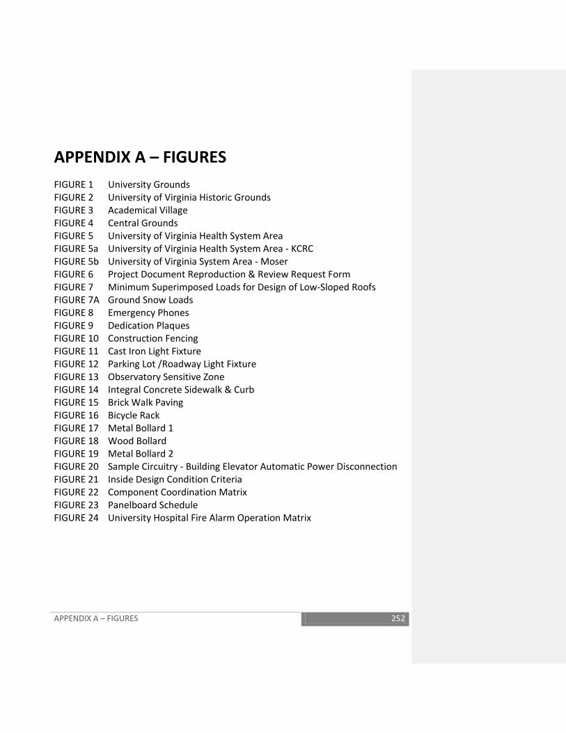
APPENDIX A – FIGURES 252
APPENDIX A – FIGURES FIGURE 1 University Grounds FIGURE 2 University of Virginia Historic Grounds FIGURE 3 Academical Village FIGURE 4 Central Grounds FIGURE 5 University of Virginia Health System Area FIGURE 5a University of Virginia Health System Area - KCRC FIGURE 5b University of Virginia System Area - Moser FIGURE 6 Project Document Reproduction & Review Request Form FIGURE 7 Minimum Superimposed Loads for Design of Low-Sloped Roofs FIGURE 7A Ground Snow Loads FIGURE 8 Emergency Phones FIGURE 9 Dedication Plaques FIGURE 10 Construction Fencing FIGURE 11 Cast Iron Light Fixture FIGURE 12 Parking Lot /Roadway Light Fixture FIGURE 13 Observatory Sensitive Zone FIGURE 14 Integral Concrete Sidewalk & Curb FIGURE 15 Brick Walk Paving FIGURE 16 Bicycle Rack FIGURE 17 Metal Bollard 1 FIGURE 18 Wood Bollard FIGURE 19 Metal Bollard 2 FIGURE 20 Sample Circuitry - Building Elevator Automatic Power Disconnection FIGURE 21 Inside Design Condition Criteria FIGURE 22 Component Coordination Matrix FIGURE 23 Panelboard Schedule FIGURE 24 University Hospital Fire Alarm Operation Matrix
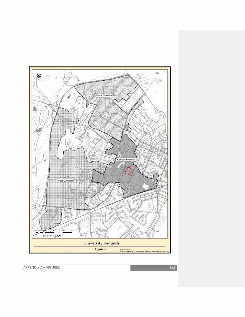
APPENDIX A – FIGURES 253
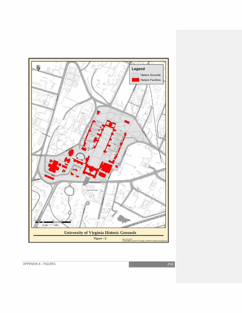
APPENDIX A - FIGURES 254
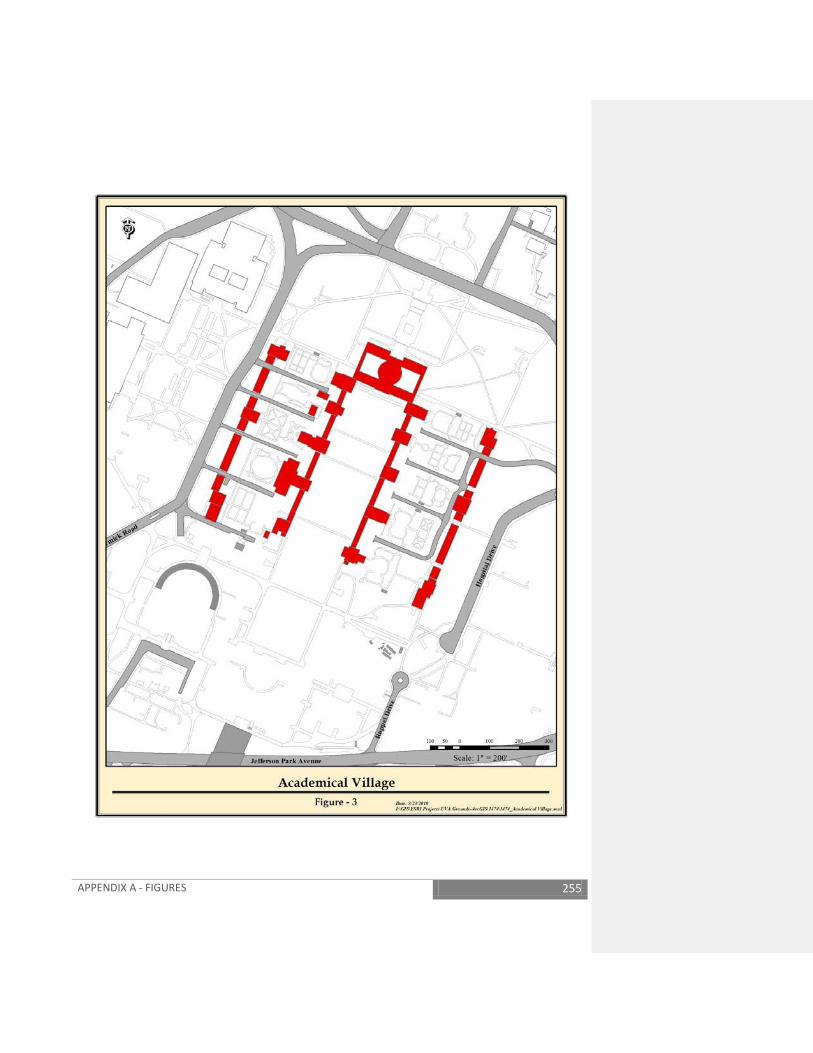
APPENDIX A - FIGURES 255
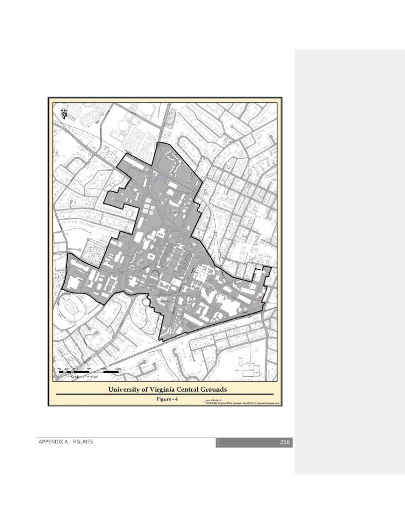
APPENDIX A - FIGURES 256
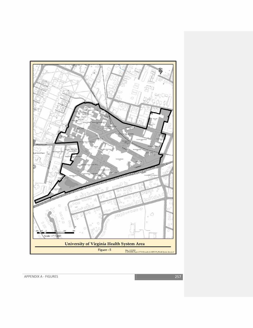
APPENDIX A - FIGURES 257
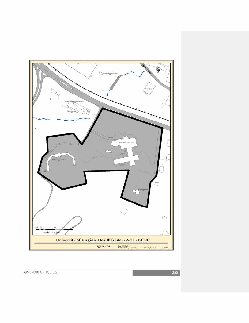
APPENDIX A - FIGURES 258
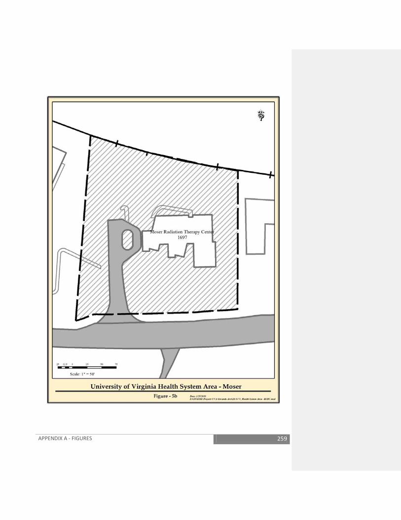
APPENDIX A - FIGURES 259

APPENDIX A - FIGURES 260
Project Document Reproduction & Review Request Date: Project Manager: Project Title: Phase: PIMS #: WO#: FM Reviewers Charge WO#: For Facilities Management Review? YES/NO (required for 50%, 65%, 95% development phases; if yes you must request a copy to be delivered to the Resource Center in Leake Lower)
Special Instructions (including non-typical review date*):
T&N Delivery Instructions Deliver to: (note: T&N will drop off at location in bold – sub distribution by receiving party)
Full Size Sets
½ Size Sets
Project Manual
Leake Upper – 575 Alderman ASBO Review ( 1 set per discipline) RESM Judy Maretta Leake Lower -Resource Center -575 Alderman Facilities Management Review Erosion & Sediment Control & Stormwater Management (Kristin Carter) – consult before requesting prints
EH&S – 515 Edgemont - Kristy Davis Davis Wing Room 1312- HSPP (Hospital Engineer) Rotunda SE - Architect for the University Blake Center - 5th floor HS FP&C Office George Southwell EP Trailer – 300 15th Street SW McKim Hall rm 3048 - Richard Allen McKim Hall Room 1162 - Richard Pearson U. Hospital G421A - Clinical Engineering ITC - 2454 Old Ivy Rd – John Robertson Charlottesville Projects Fire Marshal, 203 Ridge St – W.A. Hogsten City of Charlottesville, 605 E Main – Sujit Ekka/Khadija Abdur-Rahman U Police 2304 Ivy Rd, 202 – Michael Coleman VA State Fire Marshal - 205 Caroline Street, Orange, VA 22960, (540) 661-4661 Office, (540) 672-1560 Fax
Add other recipients with locations below as required Project Manager Facility Dynamics Hospital Epidemiology Total Documents required
Figure 6
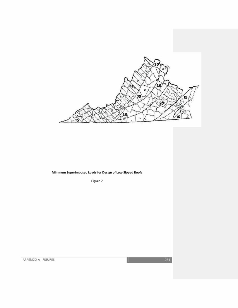
APPENDIX A - FIGURES 261
Minimum Superimposed Loads for Design of Low-Sloped Roofs
Figure 7
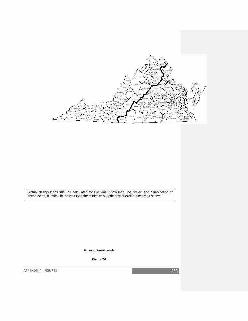
APPENDIX A - FIGURES 262
Actual design loads shall be calculated for live load, snow load, ice, water, and combination of these loads, but shall be no less than the minimum superimposed load for the areas shown.
Ground Snow Loads
Figure 7A

APPENDIX A - FIGURES 263
Figure 8
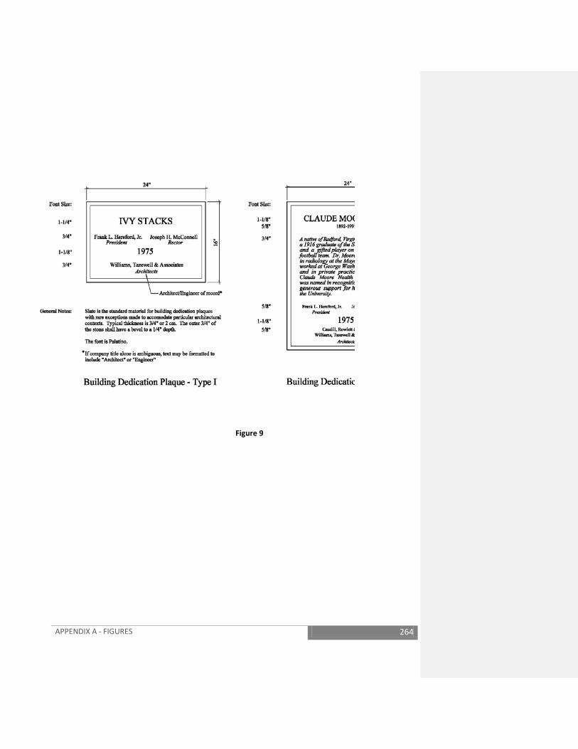
APPENDIX A - FIGURES 264
Figure 9

APPENDIX A - FIGURES 265
Figure 10
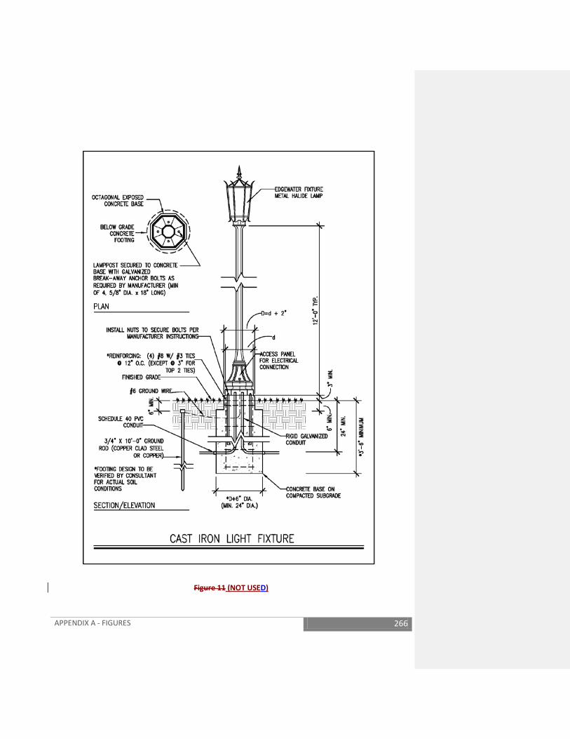
APPENDIX A - FIGURES 266
Figure 11 (NOT USED)
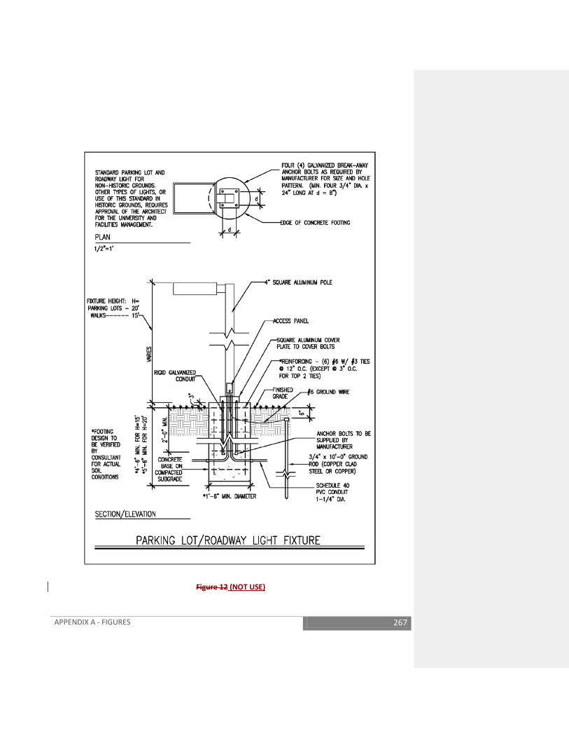
APPENDIX A - FIGURES 267
Figure 12 (NOT USE)
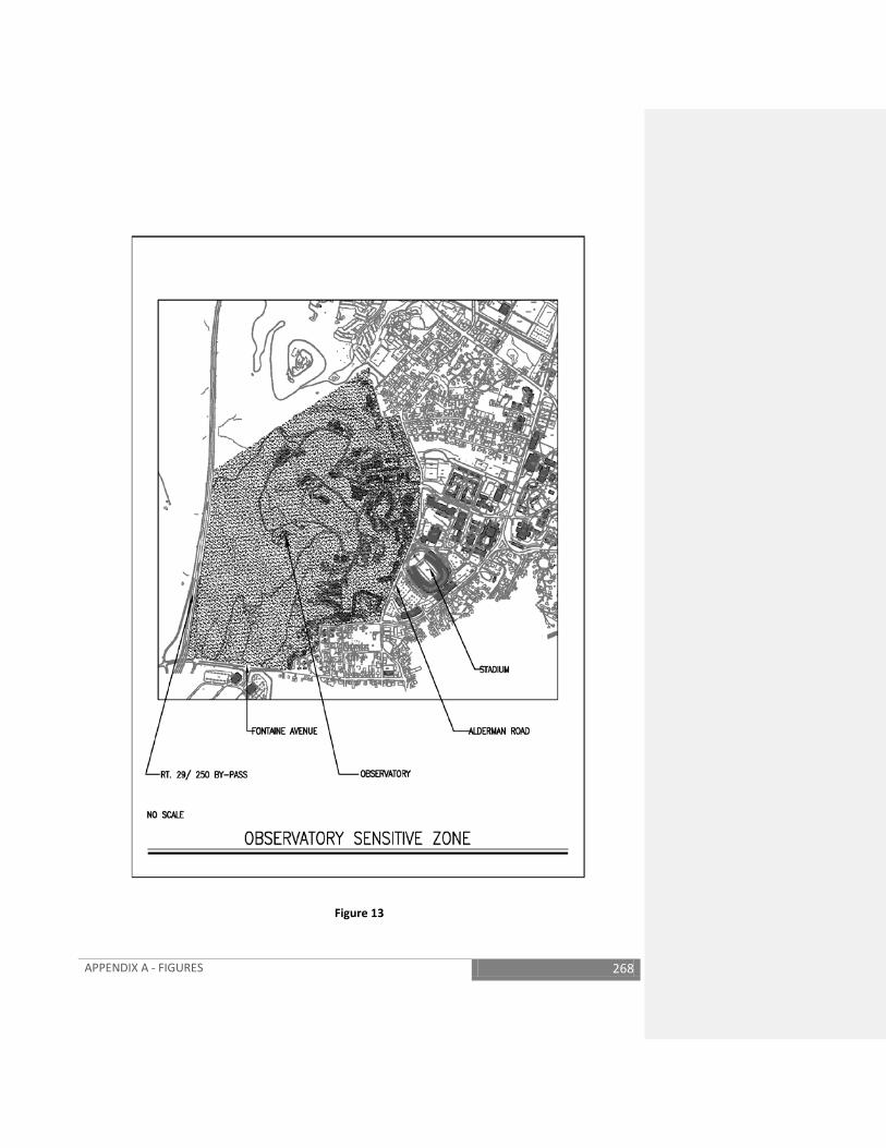
APPENDIX A - FIGURES 268
Figure 13
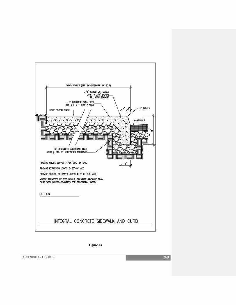
APPENDIX A - FIGURES 269
Figure 14

APPENDIX A - FIGURES 270
Figure 15
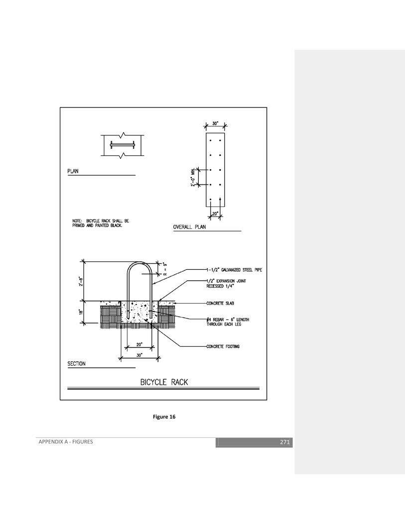
APPENDIX A - FIGURES 271
Figure 16

APPENDIX A - FIGURES 272
Figure 17

APPENDIX A - FIGURES 273
Figure 18
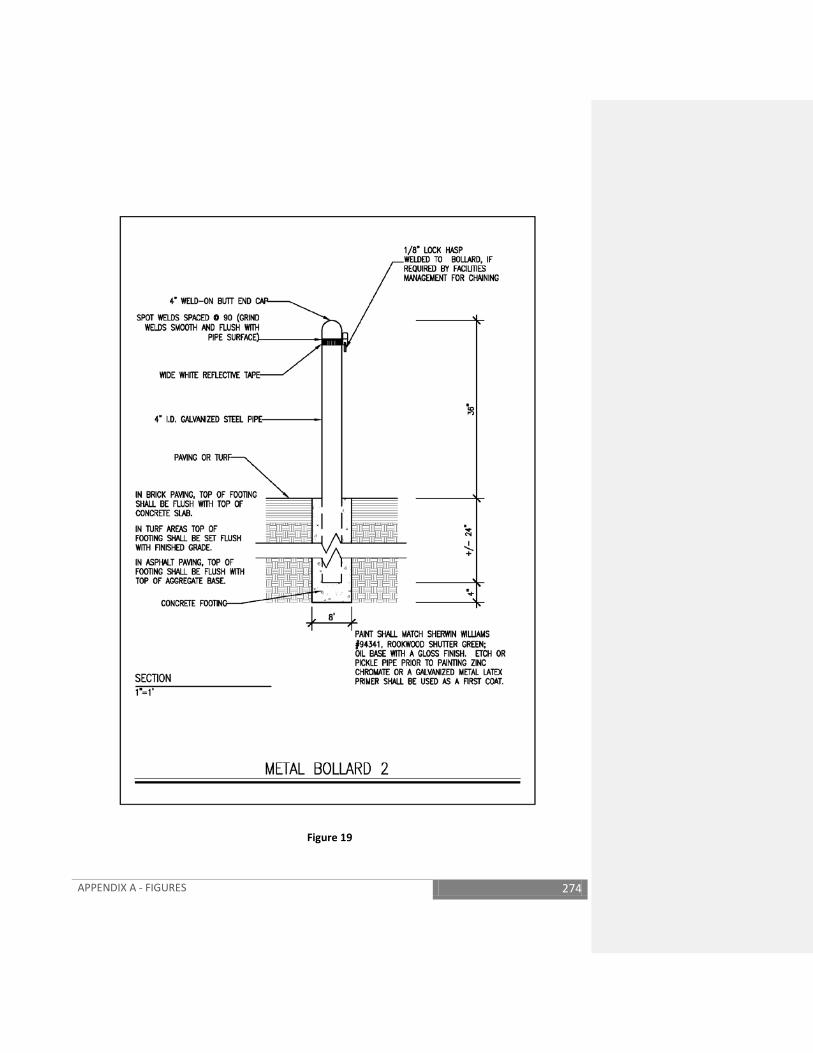
APPENDIX A - FIGURES 274
Figure 19
APPENDIX A - FIGURES 275
SAMPLE CIRCUITRY DIAGRAM
LEGEND
OPERATIONAFTER ENERGIZATION OF HEAT DETECTOR THE TIME DELAY RELAY PICKS UP WHEN PRESET TIME HAS EXPIRED. THIS TIME IS DETERMINED BY THE TOTAL ELEVATOR TRAVEL TIME IN THE LONGEST RUN TIME SCENARIO, WITH AN ADDITIONAL 10 SECONDS ADDED. WHEN THIS TOTAL TIME IS SATISIFIED THE TIMER CONTACTS ARE CLOSED, AND THAT WILL RESULT IN THE SHUNT TRIP OPERATOR BEING ENERGIZED, AND THE PRE-ACTION SPRINKLER OPERATOR BEING ENERGIZED.
TO SHUNT TRIP OPERATOR
TO PRE-ACTION SPRINKLER OPERATOR
TO ELEVATOR RECALL OPERATOR
TO ELEVATOR RECALL OPERATOR
Figure 20

APPENDIX A - FIGURES 276
INSIDE DESIGN CONDITION CRITERIA
Occupancy/Use Summer (Cooling)
Offices/Business 78°Fdb 70°Fdb Classrooms/Lecture 78°Fdb 70°Fdb Residential 78°Fdb 70°Fdb Libraries * 78°Fdb 70°Fdb Archival Storage in Libraries Special Special Art Storage in Museums Special Special Kitchens *** 85°Fdb or spot cooling 70°Fdb Warehouse, Mechanical Rooms, Storage Rooms and Electrical Rooms
Ventilate with outside air unless otherwise approved
40-55°Fdb for freeze protection
Pools ** 82°Fdb 50-60% RH Pool Water: 80°F
82°Fdb 50-60% RH Pool Water: 80°F
Hospitals
Consult the ASHRAE Guide or other applicable references
Consult the ASHRAE Guide or other applicable references
Laboratories (Educational) * 78°Fdb 30-60% RH
70°Fdb 30-60% RH
Laboratories (Research) * 75°Fdb 30-60% RH
72°Fdb 30-60% RH
Gymnasiums/Recreation, Indoor Tennis and Racquetball Courts, Weight Rooms and Aerobic Rooms ***
80°Fdb 68°Fdb
Locker Rooms/Showers *** 80°Fdb 70°Fdb
* Conditions may vary depending upon actual user justified requirements.
Deviations must be approved by the CFO. ** Cooling for type occupancy/use must be justified to and approved by the CFO. *** These occupancies/use types are not normally provided with cooling unless
justified to and approved by the CFO. Where approved, design conditions shall not exceed those indicated. Air conditioning systems shall be able to maintain an indoor relative humidity of no more than 60% regardless of the outdoor temperature and humidity, or percentage of outside air. Lower indoor humidity levels shall be maintained when justified by project criteria.
Figure 21
APPENDIX A - FIGURES 277
COMPONENT COORDINATION (scope of work/responsibility matrix – current CSI sections may be used)
Device Furnished By
Installed By
Power Wiring
Control/ Interlock
Wiring
Fire Alarm Wiring
Air Handler Devices 1 Duct Smoke Detectors 16000 15000 N/A (from
FA system)
N/A 16000
2 Duct Smoke Detector Auxiliary Contents
16000 16000 16000 17000 16000
3 Smoke Dampers at AHU’s 15000 15000 N/A 17000 N/A 4 Smoke Damper Actuators
at AHU’s 15000 15000 16000 17000 N/A
5 Fire Dampers 15000 15000 N/A N/A N/A 6 Air Flow Stations 17000 15000 N/A 17000 N/A 7 Automatic Control
Dampers (unless specified with unit)
17000 15000 N/A 17000 N/A
8 Automatic Control Damper Actuators
17000 17000 17000 17000 N/A
9 Variable Speed Drives 15000 or 16000
16000 16000 17000 N/A
10 Humidifiers 15000 15000 16000 17000 N/A 11 Humidifier Control Valve 15000 15000 N/A 17000 N/A 12 Humidifier Isolation
Valve 17000 15000 N/A 17000 N/A
13 Humidifier Airflow Switch 15000 15000 N/A 17000 N/A VAV and Terminal Units
14 Supply & Exhaust Terminal Boxes (VAV’s)
15000 15000 16000 17000 N/A
15 Terminal Flow Pick-up 15000 15000 N/A 15000 N/A 16 Terminal Damper
Actuator (if not provided by box manufacturer)
17000 15000 N/A 17000 N/A
17 Terminal DDC Controller 17000 15000 16000 17000 N/A 18 Terminal Reheat Valves 17000 15000 N/A 17000 N/A
Laboratory Controls
19 Supply, Hood Exhaust & General Exhaust Air Valves
17000 15000 N/A 17000 N/A
20 Controls at Fume Hood 17000 17000 16000 17000 N/A 21 Isolation Room Controls 17000 17000 16000 17000 N/A
APPENDIX A - FIGURES 278
Meters 22 Water Flow Meters 17000 15000 16000 17000 N/A 23 Electrical Demand
Meters 16000 16000 16000 17000 N/A
24 Steam Flow Meters 17000 15000 16000 17000 N/A Digital Control Panels
25 DDC Panels if shown on Electrical Drawings
17000 17000 16000 17000 N/A
26 DDC Panels if NOT shown on Electrical Drawings
17000 17000 16000 if 120V
17000 N/A
Control Air
27 Air Compressor 17000 15000 16000 N/A N/A 28 Air Dryer 17000 17000 16000 N/A N/A
Water Systems
29 Hydronic Control Valves 17000 15000 N/A 17000 N/A 30 Water Flow Switches for
Chiller 15000 15000 16000 17000 N/A
31 Cooling Tower 15000 15000 16000 17000 N/A Miscellaneous Systems
32 Refrigerant Monitoring 17000 17000 16000 17000 N/A 33 Split System (Heat
Pumps, etc.) 15000 15000 16000 17000 N/A
34 Chemical Feed Systems 15000 15000 16000 17000 N/A 35 Kitchen Hood System 15000 15000 16000 16000 or
17000 16000
Figure 22

APPENDIX A - FIGURES 279
Figure 23

APPENDIX A - FIGURES 280
Figure 24
APPENDIX A - FIGURES 281
Figure 25

APPENDIX B – ROOF INSPECTION FORMS AND PROCEDURES 282
APPENDIX B –ROOF INSPECTION FORMS AND PROCEDURES
The Roof Inspector
The minimum qualifications below serve as criteria for the University if selecting an outside, full-time roofing inspector:
1. The Inspector should have a thorough knowledge of roofing details, flashing, and systems
employing single-ply, built-up, metal, shingle, slate, or other membranes as the main weatherproof barrier.
2. The Inspector should have attended at least three formal schools/seminars (for example: AIA,
BURSI, RCI, CSI, NRCA or RIEI seminars) providing no less than a total of four (4) continuing education units, have a registered roof observer registration from RCI (or a Quality Assurance Observer Certificate from RIEI for the roof system to be observed) or have equivalent training as approved by the University.
3. He should be thoroughly familiar with the latest edition of the NRCA Roofing and Waterproofing
Manual. 4. The Inspector should have a minimum of five years of full-time, practical roofing experience or
approved equivalent experience. 5. He should identify, in writing, at least three (3) projects where he has been the full-time roofing
inspector. He should provide names, addresses, and telephone numbers of roof owners and A/E for the roof projects.
6. He should be trained and competent in the services he is providing. 7. Roof Inspector’s Scope of Work:
a. The Inspector shall monitor the Work continuously during installation of the roof. b. He shall monitor the Work for compliance with the Contract Documents and the
University’s Roofing Policy. c. He shall immediately report any deviations from the Contract Documents, the
University’s Policy, or good roofing practice to the Architect and University. A written report shall follow an oral report.
d. The Inspector may recommend suspension of Work or rejection of non-complying Work to the A/E and University.
e. He shall not: 1. Allow roofing materials to be installed until the manufacturer’s certification that
the roofing materials comply with specified ASTM or other approved standards
APPENDIX B – ROOF INSPECTION FORMS AND PROCEDURES 283
are received. He shall notify the University so that appropriate action can be taken.
2. Authorize deviations from the Contract Documents. 3. Enter the area of responsibility of the Contractor’s superintendent. 4. Issue orders on any aspect of construction means, methods, techniques,
sequences, procedures, or safety in connection with the Work.
f. The Inspector shall keep a daily log (refer to the form at end of this appendix) for each Project and shall give a copy of the log to the roofing Contractor. The Inspector shall record all pertinent information such as weather, daily progress, and workers on the job, material storage, deck condition, bitumen temperature, installation procedures, and quality of workmanship, job-related visitors, and so forth.
The Roof Consultant The Consultant should have the following qualifications: 1. Roof consulting and testing Services should be the Consultant’s full-time occupation. 2. He should have a minimum of five years of field experience in providing the service. 3. He should have completed at least three service contracts in the recent past. Work for each of
the completed contracts should be roughly equivalent in size and complexity to the proposed work.
4. He should be required to submit three complete surveys of roofs that were repaired, recovered,
or replaced; names, addresses and telephone numbers of roof owners; and A/Es responsible for preparing the drawings and specifications.
5. He should have attended at least three formal roofing schools/seminars (RIEI, BURSI, RCI, NRCA,
AIA, CSI Seminars, for example). The seminars should be the type that gives CEU (Continuing Education Unit) credits. A minimum total of four (4) CEU credits should have been received.
6. He should be trained, experienced and competent in performing required services. 7. If testing is required, he shall be appropriately trained, certified, licensed in the testing
procedures (infrared, nuclear, electrical capacitance surveys; core sampling; ASTM procedures; gravimetric analysis; and so forth) required for the service.
8. He should submit resumes of his firm and all employees participating in the service. 9. His resume should describe other related Services and contributions, such as writing, lecturing,
and serving as an expert witness that he has provided. He should list any Professional qualifications or licenses.
10. The resume form must be submitted with the roof Consultant’s response to the University’s
RFP. It will be used with other requested items to evaluate the applicant.

APPENDIX B – ROOF INSPECTION FORMS AND PROCEDURES 284
Non-Destructive (NDE) Roofing Surveys
A non-destructive (NDE) Survey uses infrared or nuclear and electric capacitance moisture detection equipment to locate unacceptable moisture within a roofing system. An infrared or nuclear survey may be used alone; electric capacitance is acceptable only if it issued with infrared or nuclear surveys.
An NDE survey is mandatory before a newly constructed roof may be accepted. Depending on the size and condition of an existing roof, a survey may or may not be required before an Agency may repair or replace the roof. The following outlines requirements for NDE surveys:
1. Equipment, subject to the University’s approval, shall be equal to the following:
a. Infrared: AGA 720 system or Inframetrics 520 system b. Nuclear: Seaman Troxler 3216 Roof Reader, Nuclear Model R-50 or later model c. Electrical Capacitance: As approved by the University
2. Surveys
a. Infrared: Provide a complete survey of the roof or roofs. Outline all anomalies with spray paint. Provide a thermogram showing the outlines and daylight photographs of all anomalies. If video thermogram imaging is used, provide the University with the video tape of the survey. Roof markings, therogram, and photographs shall be numbered so that features can be readily identified and coordinated.
Walkover surveys shall be performed in a pattern of 20’-0” maximum (20 foot maximum distance between walk paths), however the distance between walk paths shall not exceed the sensitivity of the instrument being used. Instrument sensitivity shall permit recognition of areas of wet insulation as small as 6 inches on a side. Surveys, inspection procedures, reports, etc. shall be conducted in accordance with the requirements and procedures in ASTM C1153, “Standard Practice for the Location of Wet Insulation in Roofing Systems Using infrared Imaging”, except of otherwise noted in this Appendix.
b. Nuclear: Provide a grid, comprising 5’-0” on-a-side grid unit, to completely cover the roof or roofs. Mark each grid intersection with spray paint. Take readings at the inter-sections and record them on a roof plan. Provide daylight photographs of anomalies.
3. Core Samples
Since NDE surveys are not able to measure moisture in roofs directly – nuclear equipment responds to hydrogen emissions, infrared to heat changes – core samples to measure actual moisture content must be taken from surveyed roofs and correlated with NDE readings. The samples shall be taken as follows:

APPENDIX B – ROOF INSPECTION FORMS AND PROCEDURES 285
a. One is required on roofs showing no anomalies. Additional cores are not required if the Consultant can show that moisture is not causing detected anomalies. The consultant shall identify such anomalies and explain their cause in a written report to the University.
b. On all other roofs a minimum of one dry and one wet core shall be taken from each roof
surveyed.
c. As many cores as needed should be taken to establish moisture counts and changes, but no more than five cores shall be taken from any roof.
4. Gravimetric Analysis
As soon as possible after samples are taken, cores should be sealed in air tight containers and taken to the laboratory for analysis.
a. Analyze samples gravimetrically to determine percent of moisture in any required core sample taken from new roofs and, unless waived for justifiable reasons, from existing roofs.
b. Identify all materials – surfacing, membrane (and number of plies), insulation, vapor
barriers, adhesives, etc. – in the cores. 5. Moisture Conditions
The surveyor shall correlate survey reading results with actual moisture conditions determined by core samples gravimetrically analyzed. The correlation shall be shown or tabulated on the drawings.
6. Report
The consultant shall submit a written report explaining what the problems are, what to do about them, and what the costs are. Specifically, the report shall:
a. Identify and describe all anomalies.
b. Identify and describe any visual survey defects that may be harmful to the roof.
c. Give the causes for each anomaly and defect.
d. Recommend alternate courses of corrective action for defects and anomalies harmful to the roof.
e. Provide the cost for correcting the defects and anomalies.

APPENDIX B – ROOF INSPECTION FORMS AND PROCEDURES 286
Drawings
The consultant hired to survey roofs shall provide plans complying with the following:
1. General Requirements are:
(1) Print size, preferably, should be 24” X 36”; but in no case larger than 36” X 46”. (2) Minimum drawing scale is 1/8” = 1’0” for roofs or portions of roofs surveyed. (3) Provide one reproducible print (Mylar, etc.) and two non-reproducible prints, as a
minimum, for each sheet of drawings. 2. A legend defining all symbols and explaining abbreviations. Drawings shall show the following as
a minimum:
(1) All roofs surveyed (2) State identification, title, and date (3) An orientation north arrow and drawing scale (4) The area of each roof and approximate overall dimensions.
3. All existing features, equipment, and roof penetrations of whatever nature (such as vents,
stacks, drains, hatches, skylights, screens, railings, mechanical equipment, etc.) shall be accurately indicated, identified, and drawn to scale.
4. All roof slopes and valleys noted with drainage arrows. If there is no slope, state that the roof is
dead level. 5. Where flashing is carried to a vertical surface, identify the surface (roof vent, masonry parapet,
etc.) and give its height from roof level. 6. For a visual survey, show and explain all roofing defects and anomalies. Show interior damage
(to the roof system) by dotted line. 7. For an infrared survey, accurately delineate moisture anomalies with contour lines; for a nuclear
survey, show all grid point readings and define areas having unacceptable moisture by contour lines. Show where core samples were taken. Correlate nuclear grid point readings and infrared contour changes to percent of moisture. Dimension areas recommended for removal and locate them with respect to fixed identifiable features (such as parapets).
8. Provide at least one detail section (3/4” = 1’0” minimum) showing roof construction where core
samples were taken; more if there are differences in construction from core to core. Identify surfacing material, membrane product, insulation type and thickness, vapor barrier if used, and deck construction.

APPENDIX B – ROOF INSPECTION FORMS AND PROCEDURES 287
ROOFING FORMS
Standard DGS forms and formats are available for download from the DGS Forms Center (http://dgs.state.va.us/Forms/tabid/119/Default.aspx). The following roofing forms are available for download from the Forms Center:
Form #
Description
File Type
DGS-30-328 Roofing – Installation History Word DGS-30-332 Roofing – Built-up Roofing Data Word DGS-30-336 Roofing – Metal Roofing Data Word DGS-30-340 Roofing – Shingle Roofing Data Word DGS-30-344 Roofing – Single Ply Roofing Data Word DGS-30-348 Roofing – Inspection Checklist Word DGS-30-352 Roofing – Daily Inspection Log Word DGS-30-356 Roofing Consultant/Inspector Resume Word
To view/download the latest version of a form, visit the website listed above and enter the Form # (e.g., DGS-30-328) in the search box on the Forms Center. Additional instructions for viewing and downloading forms are available in the Help Guide on the DGS Forms Center.
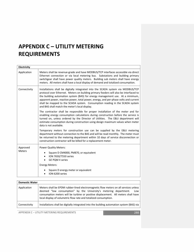
APPENDIX C – UTILITY METERING REQUIREMENTS 288
APPENDIX C – UTILITY METERING REQUIREMENTS Electricity
Application Meters shall be revenue-grade and have MODBUS/TCP interfaces accessible via direct Ethernet connection or via local metering bus. Substations and building primary switchgear shall have power quality meters. Building sub meters shall have energy meters. All meters shall have a local display of demand and totalized consumption.
Connectivity Installations shall be digitally integrated into the SCADA system via MODBUS/TCP protocol over Ethernet. Meters on building primary feeders will also be interfaced to the building automation system (BAS) for energy management use. At a minimum, apparent power, reactive power, total power, energy, and per-phase volts and current shall be mapped to the SCADA system. Consumption reading in the SCADA system and BAS shall match the meter's local display.
The contractor shall be responsible for proper installation of the meter and for enabling energy consumption calculations during construction before the service is turned on, unless ordered by the Director of Utilities. The E&U department will estimate consumption during construction using design maximum values when meter data is not available.
Temporary meters for construction use can be supplied by the E&U metering department without connection to the BAS and will be read monthly. The meter must be returned to the metering department within 10 days of service disconnection or construction contractor will be billed for a replacement meter.
Approved Meters
Power Quality Meters:
• Square D CM4000, PM870, or equivalent • ION 7650/7550 series • GE PQM II series
Energy Meters:
• Square D energy meter or equivalent • ION 6200 series
Domestic Water
Application
Meters shall be EPDM rubber-lined electromagnetic flow meters on all services unless deemed "low consumption" by the University's metering department. Low consumption meters will be turbine or positive displacement. All meters shall have local display of volumetric flow rate and totalized consumption.
Connectivity Installations shall be digitally integrated into the building automation system (BAS) via

APPENDIX C – UTILITY METERING REQUIREMENTS 289
BACNet protocol. Totalization, volumetric flow rate, and diagnostic data shall be mapped into the BAS. Totalization value in the BAS shall match the meter's local display.
Turbine and positive displacement meter installations shall output to the BAS. The local meter value and BAS totalization value should match. This will be recalibrated during PM.
The contractor shall be responsible for proper installation of the meter and for enabling consumption calculations during construction before the service is turned on, unless ordered by the Director of Utilities. The E&U department will estimate consumption during construction using design maximum values when meter data is not available.
Temporary meters for construction use can be supplied by the E&U metering department without connection to the BAS and will be read monthly. The meter must be returned to the metering department within 10 days of service disconnection or construction contractor will be billed for a replacement meter.
Approved Meters
Magnetic Flow meters:
• Toshiba LF series • Johnson-Yokogawa ADMAG series • Siemens/Controlotron SITRANS F series
Chilled Water & Heating Hot Water
Application Transit-time ultrasonic energy meters may be used on all pipe sizes and shall be used for services greater than 6”. Services at or below 6” may use TEFLON-lined magnetic flow meters. Matched temperature sensors for energy meters shall be installed in thermowells. All meters shall have local display of energy demand, volumetric flow rate and totalized energy consumption. Meters shall have 10 unobstructed pipe diameters of straight pipe upstream and 5 pipe diameters downstream.
Connectivity All installations shall be digitally integrated into the BAS via BACNet protocol. Totalization, energy and volumetric flow rates, supply/return temperatures and diagnostic data shall be mapped into the BAS. Meter shall calculate and display energy consumption without BAS support. Totalization values in the BAS shall match the meter's local display.
The contractor shall be responsible for proper installation of the meter and for enabling energy consumption calculations during construction before the service is turned on, unless ordered by the Director of Utilities. The E&U department will estimate consumption during construction using design maximum values when the utility is in service and meter data is not available.
Approved Meters
Ultrasonic flow/energy meters:
• Flexim FLUXUS series • Siemens/Controlotron SITRANS F series

APPENDIX C – UTILITY METERING REQUIREMENTS 290
• Dynasonics TFX series clamp-on (for <2” CHW services)
Magnetic flow meters:
• Toshiba LF-series • Johnson-Yokogawa ADMAG series • Siemens SITRANS F series
Steam
Application Meters shall be spring-loaded, variable area meters for applications up to 8". For service sizes greater than 8", vortex shedding meters shall be used. Meters shall have 10 unobstructed pipe diameters of straight pipe upstream and 5 pipe diameters downstream.
Ceramic lined electromagnetic flow meters shall be installed for steam condensate and must be approved by the metering department when a steam flow meter cannot be installed.
All meters shall have a local display of demand, totalized consumption, and compensation input values where applicable.
Connectivity All installations shall be digitally integrated into the BAS via MODBUS or BACNet protocols. Totalization, flow rates, and diagnostic data shall be mapped into the BAS. Steam meters shall calculate and display energy or mass flow rate demand and total consumption without BAS support. Condensate meters shall calculate and display volumetric flow demand and consumption. Totalization values in the BAS shall match the meter's local display. Steam meter installations that require a flow computer for compensation calculations shall integrate the computer with the BAS via BACnet or MODSUB protocols.
The contractor shall be responsible for proper installation of the meter and for enabling energy consumption calculations during construction before the service is turned on, unless ordered by the Director of Utilities. The E&U department will estimate consumption during construction using design maximum values when the utility is in service and meter data is not available.
Approved Meters
Spring-loaded variable area meters:
• Spirax-Sarco Gilflo, ILVA, or DIVA series
Flow Computers:
• Spirax-Sarco M800 series • KEP SuperTROL series
Vortex meters:
• EMCO Vortex-PhD series • Spirax-Sarco V-Bar series • Sierra Instruments Innova-Flo series
Magnetic flow meters:

APPENDIX C – UTILITY METERING REQUIREMENTS 291
• Toshiba LF-series • Johnson-Yokogawa ADMAG series • Siemens SITRANS F series
Oil
Application Meters shall be ultrasonic transit-time meters for all applications. Meters shall have a local display of demand and totalized consumption.
Connectivity Installations shall be digitally integrated into the building automation system (BAS) via BACNet protocol. Totalization, volumetric flow rate, and diagnostic data shall be mapped into the BAS. Totalization value in the BAS shall match the meter's local display.
The contractor shall be responsible for proper installation of the meter and for enabling consumption calculations during construction before the service is turned on, unless ordered by the Director of Utilities. The E&U department will estimate consumption during construction using design maximum values when meter data is not available.
Approved Meters
Ultrasonic flow meters:
• Siemens/Controlotron SITRANS series • Dynasonics TFX-series clamp-on
Natural Gas
Application Meters shall be vortex shedding meters for all applications. Meters shall have a local display of demand and totalized consumption.
Connectivity Installations shall be digitally integrated into the building automation system (BAS) via BACNet protocol. Totalization, volumetric flow rate, and diagnostic data shall be mapped into the BAS. Totalization value in the BAS shall match the meter's local display.
The contractor shall be responsible for proper installation of the meter and for enabling consumption calculations during construction before the service is turned on, unless ordered by the Director of Utilities. The E&U department will estimate consumption during construction using design maximum values when meter data is not available.
Approved Meters
Vortex meters:
• Spirax-Sarco V-Bar series • EMCO Vortex-PhD series • Sierra Instruments Innova-Flo series

APPENDIX D – ELEVATORS 292
APPENDIX D - ELEVATORS A. PURPOSE
This Appendix supplements BSRV 2 VERTICAL TRANSPORTATION as a required methodology to address the proven need for non-proprietary elevator control and diagnostic equipment essential to the effective and life safety maintenance of elevators serving the academic and healthcare community at the University of Virginia and the University of Virginia College at Wise.
The following outline specifications are intended to supplement BSRV 2 VERTICAL TRANSPORTATION and to be incorporated into specifications provided by consulting architects and engineers contracted by the University of Virginia for professional design services. These outline specifications are suited for Facilities Management use in procuring bids and/or proposals for elevator replacements.
SCOPE AND INTENT These guidelines are provided to assist with the requirements of the University for the Installation of hydraulic elevators.
Under no condition will any manufacturers or suppliers proprietary equipment, systems, or software be accepted.
All equipment shall carry a warranty period of one full year from the date of the University’s acceptance. Defects or equipment failures occurring during that one year period shall be promptly corrected at no cost to the University.
The contractor shall provide one full year of complete maintenance service as part of this warranty. This service shall include monthly maintenance inspections and emergency call-back service 24 hours a day, seven days a week. A fire service check chart will be kept in the machine room and fire recall will be tested once a month and recorded on this chart.
The service technician will be required to check in with the elevator maintenance supervisor and to check out leaving a copy of the time ticket showing all work performed.
Roped hydraulic elevators will not be permitted to be installed at the University.
All material that is specified to be used can be purchased by any elevator company.
Any questions should be directed to the Project Manager for a particular installation.
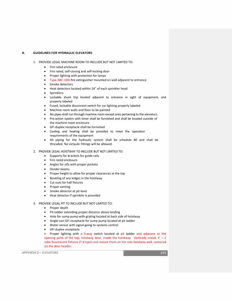
APPENDIX D – ELEVATORS 293
B. GUIDELINES FOR HYDRAULIC ELEVATORS
1. PROVIDE LEGAL MACHINE ROOM TO INCLUDE BUT NOT LIMITED TO: • Fire rated enclosure • Fire rated, self-closing and self-locking door • Proper lighting with protection for lamps • Type ABC-10lb fire extinguisher mounted on wall adjacent to entrance • Smoke detectors • Heat detectors located within 24” of each sprinkler head • Sprinklers • Lockable shunt trip located adjacent to entrance in sight of equipment, and
properly labeled • Fused, lockable disconnect switch for car lighting properly labeled • Machine room walls and floor to be painted • No pipes shall run through machine room except ones pertaining to the elevators • Pre-action system with timer shall be furnished and shall be located outside of
the machine room enclosure • GFI duplex receptacle shall be furnished • Cooling and heating shall be provided to meet the operation
requirements of the equipment • All piping for the hydraulic system shall be schedule 80 and shall be
threaded. No victaulic fittings will be allowed.
2. PROVIDE LEGAL HOISTWAY TO INCLUDE BUT NOT LIMITED TO: • Supports for brackets for guide rails • Fire rated enclosure • Angles for sills with proper pockets • Divider beams • Proper height to allow for proper clearances at the top • Beveling of any ledges in the hoistway • Cut outs for hall fixtures • Proper venting • Smoke detector at pit level • Heat detector if sprinkler is provided
3. PROVIDE LEGAL PIT TO INCLUDE BUT NOT LIMITED TO: • Proper depth • Pit ladder extending proper distance above landing • Hole for sump pump with grating located at back side of hoistway • Single non GFI receptacle for sump pump located at pit ladder • Water sensor with signal going to systems control • GFI duplex receptacle • Proper lighting with a 3-way switch located at pit ladder and adjacent to the opening jamb of the top, hoistway door, inside the hoistway. Vertically install, 4’ – 2 tube fluorescent fixtures (T-8 type) and mount them on the side hoistway wall, centered on the door header.
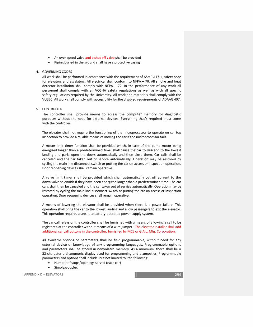
APPENDIX D – ELEVATORS 294
• An over speed valve and a shut off valve shall be provided • Piping buried in the ground shall have a protective casing
4. GOVERNING CODES
All work shall be performed in accordance with the requirement of ASME A17.1, safety code for elevators and escalators. All electrical shall conform to NFPA – 70. All smoke and heat detector installation shall comply with NFPA – 72. In the performance of any work all personnel shall comply with all VOSHA safety regulations as well as with all specific safety regulations required by the University. All work and materials shall comply with the VUSBC. All work shall comply with accessibility for the disabled requirements of ADAAG 407.
5. CONTROLLER
The controller shall provide means to access the computer memory for diagnostic purposes without the need for external devices. Everything that’s required must come with the controller.
The elevator shall not require the functioning of the microprocessor to operate on car top inspection to provide a reliable means of moving the car if the microprocessor fails.
A motor limit timer function shall be provided which, in case of the pump motor being energized longer than a predetermined time, shall cause the car to descend to the lowest landing and park, open the doors automatically and then close them. Car calls shall be canceled and the car taken out of service automatically. Operation may be restored by cycling the main line disconnect switch or putting the car on access or inspection operation. Door reopening devices shall remain operative.
A valve limit timer shall be provided which shall automatically cut off current to the down valve solenoids if they have been energized longer than a predetermined time. The car calls shall then be canceled and the car taken out of service automatically. Operation may be restored by cycling the main line disconnect switch or putting the car on access or inspection operation. Door reopening devices shall remain operative.
A means of lowering the elevator shall be provided when there is a power failure. This operation shall bring the car to the lowest landing and allow passengers to exit the elevator. This operation requires a separate battery-operated power supply system.
The car call relays on the controller shall be furnished with a means of allowing a call to be registered at the controller without means of a wire jumper. The elevator installer shall add additional car call buttons in the controller, furnished by MCE or G.A.L. Mfg. Corporation.
All available options or parameters shall be field programmable, without need for any external device or knowledge of any programming languages. Programmable options and parameters shall be stored in nonvolatile memory. As a minimum, there shall be a 32-character alphanumeric display used for programming and diagnostics. Programmable parameters and options shall include, but not limited to, the following:
• Number of stops/openings served (each car) • Simplex/duplex
APPENDIX D – ELEVATORS 295
• Single automatic push-button • Selective collective/single button collective • Programmable fire code options/fire floors (main, alternates) • Floor encoding (absolute PI)

APPENDIX D – ELEVATORS 296
• Digital PIs/single wire PIs • Programmable door times • Programmable motor limit timer • Nudging • External car shutdown input (e.g. rescuvator) • External Low Oil Sensor Input • External viscosity control input • Parking floors • Hall or car gong selection
Upon completion of the installation, the contractor shall provide two complete sets and one electronic copy all Adjuster user’s manuals, maintenance manuals, logic diagrams, computer software, access codes, password, wiring diagrams, electrical drawings, drive manuals, and all other materials required for ongoing maintenance and use of the system. The contractor shall also provide any hardware required to interface with, diagnose or maintain the system. If required, interface tools may be hand-held or built into the system, and shall function for the life of the system.
All control equipment shall be provided by Motion Control Engineering (MCE) or G.A.L. Mfg. Corporation.
The contractor, in conjunction with his sub-contractors and suppliers, shall provide the owner’s operations and maintenance personnel with instructions and training in the proper operation and maintenance of the equipment and related controls provided or altered in the work. The contractor shall also provide one spare, unique board for every board in the elevator/group controller.
Contractor shall provide for a designated Facilities Management elevator technician to attend the controller manufacturer’s training center, and the cost including travel shall be included in the elevator cost.
6. LANDING CONTROL SYSTEM Provide and install new landing control system utilizing a perforated stainless steel tape mounted in hoistway. System shall have neither rotating parts nor mechanical magnetic switches. All adjustments shall be from a digital keypad with LCD readout. All adjustments shall be self-explanatory on readout. System shall have a minimum resolution of 0.125 inches. System shall have binary floor encoding to ensure correct floor position at each floor. No mechanically adjusted or machine room encoders will be accepted.
System to be furnished by MCE or G.A.L. Mfg. Corporation.
7. PUMPING UNIT Pumping unit shall have the valve, pump, and motor located within the reservoir.

APPENDIX D – ELEVATORS 297
The unit must be mounted on sound isolation pads.
The type of valve shall be Maxton, the pump shall
be IMO. And the pump motor shall be Imperial.
The motor starter type shall be Siemens A/C
Semiconductor Motor Starter.
8. ROPED HYDRAULICS
Roped hydraulics will not be permitted to be installed at the University. No exceptions.
9. GUIDE SHOES All guide assemblies shall be roller guides and furnished by Elsco Roller Guides. The elevator jack assembly shall be located so as not to put undue pressure on any individual roller. Car must be balanced properly.
10. HOISTWAY DOOR EQUIPMENT Emergency access shall be provided at each entrance.
Top and bottom retaining devices shall be provided.
Manufacturer for all door equipment shall be GAL Mfg. Corp.
Provide hoistway access switches at the top and bottom landings.
11. CAR DOOR OPERATOR Door operators shall be furnished by GAL Mfg. Corp. The type shall be MOVFR, and shall be furnished with adjusting tool.
12. DOOR DETECTOR The door detector shall be Tri Tronics Edge Corp.
13. DOOR RESTRICTOR Door restrictor shall be furnished by G.A.L. Mfg. Corporation.
14. CAR OPERATING PANELS Car operating panels shall be vandal resistant and comply with all ADA requirements.
As part of the car operating panel the following words shall be etched into the panel: • Certificate of elevator inspection is located at Facilities Management – 575 Alderman Road. • Elevator capacity pounds • Phase II operating instructions
APPENDIX D – ELEVATORS 298
• No Smoking
Provide ADA telephone and wiring to be mounted behind car operating panel. Phone shall be furnished by TalkaPhone.
All car panels shall be furnished by PTL Mfg. Corp or Innovation Industries.
15. HALL FIXTURES All hall fixtures shall be furnished by PTL Mfg. Corp or Innovation Industries
16. LIFT NET Lift net to be provided on all units. Lift net is provided by Integrated Display Services.
17. HOSPITAL EMERGENCY SERVICE Any area with patient care shall have hospital emergency service provided at every floor and the key switch shall be operated by a USE 4 key.
18. ELEVATOR KEYS
All elevator keys shall be furnished by PTL or Innovation Industries.
C. GUIDELINE FOR GEARED ELEVATORS
1. Provide legal machine room to include but not limited to: • Fire rated enclosure • Fire rated, self-closing and self-locking door • Proper lighting with protection for lamps • Type ABC – 10lb fire extinguisher mounted on wall adjacent to entrance • Smoke detectors • Heat detectors located within 24” of each sprinkler head • Sprinklers • Lockable shunt trip located adjacent to entrance in sight of equipment, and properly
labeled • Fused, lockable disconnect switch for car lighting properly labeled • Machine room walls and floor to be painted • No pipes shall run through machine room except ones pertaining to the elevators • Pre-action system with timer shall be furnished and shall be located outside of
the machine room enclosure • GFI duplex receptacle shall be furnished • Cooling and heating shall be provided to meet the operation requirements
of the equipment
2. Provide legal hoistway to include but not limited to: • Supports for brackets for guide rails • Fire rated enclosure
APPENDIX D – ELEVATORS 299
• Angles for sills with proper pockets • Divider beams • Proper height to allow for proper clearances at the top • Beveling of any ledges in the hoistway • Cut outs for hall fixtures • Proper venting • Smoke detector at pit level • Heat detector if sprinkler is provided
3. Provide legal pit to include but not limited to: • Proper depth • Pit ladder extending proper distance above landing • Hole for sump pump with grating located at back side of hoistway • Single non GFI receptacle for sump pump located at pit ladder • Water sensor with signal going to systems control • GFI duplex receptacle
• Proper lighting with a 3way switch located at the pit ladder and adjacent to the opening jamb of the top, hoistway door, inside the hoistway. Vertically install, 4’-2 tube fluorescent fixtures (T-8 type) and mount them on the side hoistway wall, centered on the door headers.
4. GOVERNING CODES
All work shall be performed in accordance with the requirement of ASME A17.1, safety code for elevators and escalators. All electrical shall conform to NFPA – 70. All smoke and heat detector installation shall comply with NFPA – 72. In the performance of any work all personnel shall comply with all VOSHA safety regulations as well as with all specific safety regulations required by the University. All work and materials shall comply with the Virginia uniform statewide building code. All work shall comply with accessibility for the disabled requirements of ADAAG 407.
5. CONTROLLER AND VARIABLE FREQUENCY AC DRIVE UNIT The controller shall be fully programmable microprocessor based controller. The controller shall provide selective collective simplex operation, shall provide Phase I and Phase II fire service, and shall conform to all code requirements defined by Part XII of ASME A17.1-1996.
The controller system shall provide comprehensive means to access the computer memory for elevator diagnostic purposes without need for any external devices, and shall have permanent indicators to show important elevator statuses as an integral part of the controller. Systems that require attachment of external devices for troubleshooting must be submitted for approval before the successful bidder’s quotation can be evaluated. In the event that a system requiring an external device is accepted, a minimum of one (1) external device, including any/all software, passwords, parameters, etc. that may be needed for the operation of the device, shall be provided to the owner. External devices that require recharging and/or periodic reprogramming are prohibited.

APPENDIX D – ELEVATORS 300
Failure of any single magnetically operated switch, contact, or relay to release in the in-tended manner, or the failure of any static control device, speed measuring circuit, or speed pattern generating circuit to operate as intended, or the occurrence of a single acci-dental ground or short circuit shall not permit the car to start or run if any hoistway door or gate interlock is unlocked or if any hoistway door or car door or gate contact is not in the made position. Furthermore, while on car top inspection, failure of any single magnetically operated switch, contactor or relay to release in the intended manner, or the failure of any static control device to operate as intended, or the occurrence of a single accidental ground shall not permit the car to move even with the hoistway door locks and car door contacts in the closed or made position.
Dedicated permanent status indicators shall be provided on the controller to indicate the following: when the safety circuit is open, when the door locks are open, when the elevator is running at high speed, when the elevator is on independent service, when the elevator is on firefighters’ service, when the elevator out of service timer has elapsed, and when the elevator has failed to successfully complete its intended movement.
An out of service timer shall be provided which will automatically take the car out of service if the car is delayed in leaving the landing while there are calls existing in the building. The car shall not respond to hall calls while in this mode of operation, and the detector screen input shall be unresponsive in the event that a faulty screen unit was delaying the car.
Door protection timers shall be provided for both the open and close directions which will help protect the door operator motor and which will help prevent the car from being “stuck” at a landing. The door open protection timer shall cease attempting to open the door after a predetermined time in the event that the doors are prevented from reaching the open position. The door close protection timer shall reopen the doors for a short time in the event that the door-closing attempt fails to make up the door locks after a prede-termined time.
A minimum of four different door standing open times shall be provided. A car call time value shall predominate when a car call only is canceled. A hall call time value shall predominate whenever a hall call is canceled. In the event of a door reopen from the detector screen, a separate short door time value shall predominate. If the doors are prevented from closing for longer than a predetermined time, door-nudging operation shall cause the doors to move at slow speed and reduced torque in the close direction. The detector screen shall stop the door but not reverse it. A buzzer shall sound while nudging operation is activated. Hall call or car call registration and lamp acknowledgment shall be by means of a single wire per call besides the ground and power buss.
The car shall be equipped with two-way leveling to automatically bring the car within 1/4” of floor level regardless of load.
A test switch shall be provided. In the “test” position, this switch shall allow independent operation of the elevator without door open functioning for the purposes of adjustment or testing the elevator. The elevator shall not respond to hall calls in this mode of operation.

APPENDIX D – ELEVATORS 301
A timer shall be provided to limit the amount of time a car is held at a floor due to a de-fective hall call or car call including stuck pushbuttons. Call demand at another floor shall cause the car to ignore the defective call and continue to provide service in the building.
The control equipment shall have all control parameters stored permanently on erasable programmable read-only memory. (EEPROM)
The microprocessor board shall be equipped with on-board diagnostics for ease of trou-bleshooting and the field programmability of a minimum of eight (8) specific control variables. The field changes should be stored permanently using non-volatile memory.
The microprocessor board shall provide the following features:
• On board diagnostic switches and alphanumeric display. These switches and displays shall provide user-friendly interaction between the serviceman and the controller.
• On board Real Time Clock. The real time clock shall display the time and date, and shall be reset by using on board switches.
• Display of calls on a per floor basis. All types of calls shall be conveniently entered and/or displayed using on board switches and buttons. The elevator installer shall add additional car call buttons in the controller, furnished by MCE or GAL Mfg. Corporation.
• Field programmability of specific timer values. The value of these timers may be viewed and/or altered through use of the on board switches and buttons.
• Display of the status of all of the inputs, outputs, and internal control variables and flags, listed in order of their mnemonics.
The controller replacement shall include the installation of a variable frequency AC drive. Acceptable drive manufacturers are General Electric Company, and Mitsubishi Electric. Other manufactures whose product meets and/or exceeds the performance characteristics of the equipment of these manufacturers shall be accepted upon documen-tation that the equipment is “equal”. The variable frequency drive unit shall be fully compatible with and complementary to the microprocessor-based controller.
The drive shall utilize a three phase, full wave rectifier and capacitor bank to provide DC for the solid-state inverter. The solid state inverter shall utilize power semiconductor devices and a duty cycle modulation fundamental frequency of not less that one kilohertz to synthesize three phase, variable voltage, variable frequency output to operate the hoist motor in an essentially synchronous mode.
A means shall be provided for removing regenerated power from the drive DC power supply. This power shall be dissipated in resistors or returned to the three-phase AC power line. Failure of the system to remove the regenerated power shall cause drive output to be removed from the hoist motor.

APPENDIX D – ELEVATORS 302
A contactor shall be used to disconnect the hoist motor from the output of the drive unit each time the elevator stops. This contactor shall be monitored and the elevator shall not start again if the contactor has not returned to the de-energized position when the elevator stops.
The drive shall be heavy-duty type capable of delivering sufficient current required to accelerate the elevator to the contract speed (200 fpm) with the rated load (2500 lb.). The drive shall provide speed regulation appropriate to the open loop system mode.
Ambient temperature requirements (extremes) for the drive unit are -10 degrees C to +40 degrees C, and relative humidity (non-condensing) extremes are 20 to 90% RH.
The drive shall be capable of providing an adjustable DC current to the AC motor for an adjustable time in order to provide a braking pulse to use in the stopping sequence.
The drive shall have to ability to adjust or program the voltage/frequency curve as necessary to properly match the characteristics of the existing elevator hoist motor.
The drive shall not create excessive audible noise in the elevator motor.
Standard functions shall include: slip compensation, current limiting, restart after instantaneous power failure, multi-speed, jump frequency, automatic acceleration/deceleration, 2-wire/3-wire control selection, high or low limiter, bias frequency, pattern operation, selection of terminal function, terminal link.
Standard protection shall include: stall prevention, over current, over voltage, under voltage, instantaneous power failure, inverter overload, inverter overheating, motor overload, CPU error, and short circuit for input terminal.
The unit shall be self-cooling.
The controller shall provide four (4) independent speed adjustments.
The power control shall be arranged to continuously monitor the performance of the elevator such that if the car speed exceeds 150 fpm during access, inspection, or leveling the car shall shut down immediately, requiring a reset operation.
The leveling accuracy shall be within 1/4” of floor level regardless of loading conditions.
A means shall be provided in the controller to register calls without the use of jumpers. Upon completion of the installation, the contractor shall provide two complete sets and one electronic copy of all Adjuster manuals, user’s manuals, maintenance manuals, logic diagrams, computer software, access codes, password, wiring diagrams, electrical drawings, drive manuals, and all other materials required for on-going maintenance and use of the system. The contractor shall also provide any hardware required to interface with, diagnose or maintain the system. If required, interface tools may be hand-held or built into the

APPENDIX D – ELEVATORS 303
system, and shall function for the life of the system. The contractor shall also provide one spare, unique board for every board in the elevator/group controller.
All control equipment shall be provided by MCE (Motion Control Engineering) or G.A.L. Mfg. Corporation. Contractor shall provide for a designated Facilities Management elevator technician to attend the controller manufacturers training center, and the cost including traveling shall be included.
6. DUPLEX OPERATION - TWO CAR GROUP This duplex configuration, with a computer for each controller, assigns cars on a real time basis using estimated time of arrival (ETA). Should one computer lose power or become inoperative in any way, the other computer shall be capable of accepting and answering all hall calls. When both computers are in operation only one of them shall assume the role of dispatching the hall calls to both elevators.
7. MULTIPLE CAR GROUP This group configuration, with a computer for each controller, assigns cars on a real time basis using estimated time of arrival (ETA). Should one computer lose power or become inoperative in any way, the other computers shall be capable of accepting and answering all hall calls. When all computers are in operation only one of them shall assume the role of dispatching the hall calls to the other elevators.
D. SPECIAL OPERATING FEATURES
1. INDEPENDENT SERVICE The car shall be provided with a switch to remove it from operation and it shall operate in response to car calls only in an in car independent mode of operation.
2. DOOR TIMING Separate adjustable timing shall be provided to establish independent minimum passenger transfer times for car stops, hall stops, main lobby stops and door reversal protection.
3. DOOR NUDGING OPERATION Should the doors be held open due to a stuck call button or the failure of an electronic door reopening device for a predetermined adjustable time, a buzzer shall sound and the doors shall close at a reduced torque of 2.5 ft/lb. or less, permitting the car to run.
4. EMERGENCY POWER OPERATION When emergency power is detected, cars shall return to the main lobby one elevator at a time, and remain there with doors open. While each car is being returned, the other cars shall be shut down so as not to overload the emergency power generator. Once all cars have been returned to the lobby, one or more cars may be selected to run under emergency power, depending on the capability of the emergency power generator.

APPENDIX D – ELEVATORS 304
Selection of the cars that run under emergency power shall be done automatically by the group system. This automatic selection may be overridden through manual selection. The actual number of cars allowed to run under emergency power shall be a preprogrammed value and the number of cars allowed to run shall not exceed this value.
The panel for the manual selection switches for each group of elevators will be installed at a location determined by the University.
The contractor, in conjunction with his sub-contractors and suppliers, shall provide the owner’s operations and maintenance personnel with instructions and training in the proper operation and maintenance of the equipment and related controls provided or altered in the work.
Training shall be provided for a designated Facilities Management elevator technician, and the cost including traveling shall be included in the elevator cost.
5. LANDING CONTROL SYSTEM Provide and install new landing control system utilizing a perforated stainless steel tape mounted in hoistway. System shall have neither rotating parts nor mechanical magnetic switches. All adjustments shall be from a digital keypad with LCD readout. All adjustments shall be self-explanatory on readout. System shall have a minimum resolution of 0.125 inches. System shall have binary floor encoding to ensure correct floor position at each floor. No mechanically adjusted or machine room encoders will be accepted.
System to be furnished by MCE or G.A.L. Mfg. Corporation.
6. GUIDE SHOES All guide assemblies shall be roller guides and furnished by Elsco Roller Guides. Car must be balanced properly.
7. BRAKE
Manufacturer shall be Hollister Whitney
8. ROPES Ropes shall be furnished with wedge sockets.
9. MACHINES All geared machines, car sheaves and deflector sheaves shall be manufactured by Hollister Whitney.
10. GOVERNOR AND TENSION SHEAVE The governor and the pit tension sheave shall be manufactured by Hollister Whitney.
11. HOISTWAY DOOR EQUIPMENT Emergency access shall be provided at each entrance.
APPENDIX D – ELEVATORS 305
Top and bottom retaining devices shall be provided. Manufacturer for all door equipment shall be GAL Mfg. Corp. Provide hoistway access switches at the top and bottom landings.
12. CAR DOOR OPERATOR Door operators shall be furnished by GAL Mfg. Corp. The type shall be MOVFR, and shall be furnished with adjusting tool.
13. DOOR DETECTOR The door detector shall be furnished by Tri Tronics Edge Corp.
14. DOOR RESTRICTOR Door restrictor shall be furnished by G.A.L. Mfg. Corporation.
15. CAR OPERATING PANELS Car operating panels shall be vandal resistant and comply with all ADA requirements.
As part of the car operating panel the following words shall be etched into the panel: • Certificate of elevator inspection is located at Facilities Management – 575
Alderman Road • Elevator capacity pounds • Phase II operating instructions • No Smoking
Provide ADA telephone and wiring to be mounted behind the car operating panel. Phone shall be furnished by TalkaPhone.
All car panels shall be furnished by PTL Mfg. Corp or Innovation Industries.
16. HALL FIXTURES All hall fixtures shall be furnished by PTL Mfg. Corp or Innovation Industries.
17. LIFT NET
Lift net to be provided on all units. Lift net is provided by Integrated Display Services. 18. HOSPITAL EMERGENCY SERVICE
Any area with patient care shall have hospital emergency service provided at every floor and the key switch shall be operated by a USE 4 key.
19. ELEVATOR KEYS All elevator keys to be furnished by PTL or Innovation Industries.

APPENDIX D – ELEVATORS 306

APPENDIX E – SECURITY REFERENCES 307
APPENDIX E - SECURITY REFERENCES CPTED (CRIME PREVENTION THROUGH ENVIRONMENTAL DESIGN)
A. CPTED INTRODUCTION - CONCEPTS
CPTED is the practice of designing and the effective use of the physical, built environment, to deter and reduce the incidence of crime; thereby, enhance the quality of life. The application of CPTED principles during the design processes is simple and seamless when incorporated into the early phases of design. If the site and the building are planned well, the opportunity for crime and bad behavior can be suppressed or eliminated.
The concepts of CPTED are based on three simple precepts: Natural Access Control Natural Surveillance Territoriality
These concepts should be considered during site planning and internal planning of the project. Issues of safety and security will be initially programmed and brought up during design development. The implementation of these concepts is achieved through developing and applying strategies during the design process. These strategies are unique and specific to each project; therefore the designer must thoughtfully evaluate the concepts and their application.
The reader is encouraged to read the GENERAL REQUIREMENTS GR 5.3 Security, for other specific design requirements of the University. The concepts presented here are theoretical and the designer must still comply with the requirement of the Virginia Uniform Statewide Building Code in effect.
1. Natural Access Control
Natural access control limits the opportunity for crime by taking steps to clearly differentiate between public space and private space. By selectively placing entrances and exits, fencing, lighting and landscape to limit access or control flow, natural access control occurs. This design concept is directed to decreasing the opportunity for crime by placing obstacles to potential targets and therefore creating a perception of risk to the potential offender. People are physically guided through a space by the strategic design of streets sidewalks building entrances, landscaping and gateway. Within buildings the design of interior spaces and there interaction and adjacencies of programmatic functions have similar effects. Design elements are also useful tools to clearly indicate public routes and discourage access to private areas.
APPENDIX E – SECURITY REFERENCES 308
Natural access control also utilizes physical and mechanical means of controlling access through locks, alarm systems, signs, etc.
Locate common areas as centrally as possible or near major circulation paths within the project. Avoid remote locations for common areas.
2. Natural Surveillance
Natural surveillance is a design concept that limits the opportunity for crime by taking steps to increase the perception that people can be seen. Natural surveillance occurs by designing the placement of physical features, activities and people in such a way as to maximize visibility and foster positive social interaction among legitimate users of private and public space. This design concept is directed towards keeping intruders under observation, and therefore less likely to commit criminal acts making offenders behavior easily noticeable. Potential offenders feel increased scrutiny and limitations on their actions.
Natural surveillance utilizes design features to increase the visibility of a property or a building. Features that maximize the visibility of people, parking areas and building entrances include unobstructed doors and windows, pedestrian-friendly sidewalks and streets, and appropriate nighttime lighting.
Designers should provide a good visual connection between public and private environments or functions with the placement of high activities functions adjacent to potential isolated areas.
3. Territoriality
Territoriality is the concept of promoting social control through increased definition of space and reinforcing ownership. An environment designed to clearly delineate private space does two things. Owners have a vested interest and are more likely to challenge intruders or report them to the police. Second, the sense of owned space creates an environment where "strangers" or "intruders" stand out and are more easily identified. Additionally, these objectives can be achieved by assignment of space to designated users in previously unassigned locations. Territorial reinforcement measures make the normal user feel safe and make the potential offender aware of a substantial risk of apprehension or scrutiny.
By using buildings, fences, pavement, signs, lighting and landscaping to express ownership and define public, semi-public and private space, natural territorial reinforcement occurs.
People take more interest in something they own or when they feel intrinsically involved. Therefore, the environment should be designed to clearly delineate private spaces. Provide obvious defined entries, patios, balconies and terraces. Use low walls, landscape and paving patterns to delineate ownership and responsibility.

APPENDIX E – SECURITY REFERENCES 309
B. CPTED APPLICATION - STRATEGIES
Strategies are unique and site specific to each design. They must be developed to address the circumstances that are created as a consequence of the design process. Listed below are some examples of design strategies for each of the concepts above. The list is not meant to be inclusive.
1. Natural Access Control • Use a single, clearly identifiable, point of entry • Use structures to divert persons to reception areas • Incorporate maze entrances in public restrooms (where permitted by building
program). This avoids the isolation that is produced by an anteroom or double door entry system
• Use low, thorny bushes beneath ground level windows. • Eliminate design features that provide access to roofs or upper levels • In front yards, use waist-level, picket-type fencing along residential property lines to
control access, encourage surveillance • Use a locking gate between front and backyards • Use shoulder-level, open-type fencing along lateral residential property lines
between side yards and extending to between back yards. They should be sufficiently unencumbered with landscaping to promote social interaction between neighbors
• Use substantial, high, closed fencing (for example, masonry) between a backyard and a public alley
Natural access control is used to complement mechanical and operational access control measures, such as target hardening.
2. Natural Surveillance • Place windows overlooking sidewalks and parking lots • Use passing vehicular traffic as a surveillance asset • Create landscape designs that provide surveillance, especially in proximity to
designated points of entry and opportunistic points of entry • Use the shortest, least sight limiting fence appropriate for the situation • Use transparent weather vestibules at building entrances • When creating lighting design, avoid poorly placed lights that create blind-spots for
potential observers and miss critical areas. Ensure potential problem areas are well-lit: pathways, stairs, entrances/exits, parking areas, ATMs, phone kiosks, mailboxes, bus stops, children's play areas, recreation areas, pools, laundry rooms, storage areas, dumpster and recycling areas, etc.
• Avoid too-bright security lighting that creates blinding glare and/or deep shadows, hindering the view for potential observers. Eyes adapt to night lighting and have trouble adjusting to severe lighting disparities. Using lower intensity lights often requires more fixtures
APPENDIX E – SECURITY REFERENCES 310
• Use shielded or cut-off luminaries to control glare • Place lighting along pathways and other pedestrian-use areas at proper heights for
lighting the faces of the people in the space (and to identify the faces of potential attackers)
Natural surveillance measures can be complemented by mechanical and organizational measures. For example, closed-circuit television (CCTV) cameras can be added in areas where window surveillance is unavailable.
3. Territoriality
• Maintained premises and landscaping such that it communicates an alert and active presence occupying the space
• Provide trees in residential areas. Research results indicate that, contrary to traditional views within the law enforcement community, outdoor residential spaces with more trees are seen as significantly more attractive, safer, and more likely to be used than similar spaces without trees
• Restrict private activities to defined private areas • Display security system signage at access points • Avoid using cyclone fencing and razor-wire fence topping, as it communicates the
absence of a physical presence, and cues a reduced risk of being detected • Placing amenities such as seating or refreshments in common areas in a commercial
or institutional setting helps to attract larger numbers of desired users • Programming activities in common areas increases proper use, attracts more people
and increases the perception that these areas are controlled
Territorial reinforcement measures make the normal user feel safe and make the potential offender aware of a substantial risk of apprehension or scrutiny.
C. CPTED RESOURCES 1. BOOKS
Crowe, Timothy. Crime Prevention Through Environmental Design. Stonehan, MA: Butterworth-Heinemann, 1991.
Jacobs, Jane. The Death and Life of Great American Cities. New York, NY: Random House, 1961.
2. WEB PUBLICATIONS
General Guidelines for Designing Safer Communities City of Virginia Beach Municipal Center/Police Department 2509 Princess Anne Rd Virginia Beach, VA 23456-9064 www.vbgov.com (757) 563-1066 FAX (757) 563-1064 [email protected]
APPENDIX E – SECURITY REFERENCES 311
Crime Prevention Through Environmental Design: A guide to creating safer environments in Chesterfield County, Virginia Chesterfield County Police Department Support Services Division/Crime Prevention Unit Clover Hill Police Support Facility 2730 Hicks Road Chesterfield, Virginia 23235 (804) 674-7006 [email protected]
Safety by Design: Creating a safer Environment in Virginia, Crime Prevention Through Environmental Design: Guidelines Virginia CPTED Committee Virginia Crime Prevention Association Clover Hill Police Support Facility 2730 Hicks Road Chesterfield, Virginia 23235 (804) 674-7006 [email protected]


![[Knowledge][Design]Guideline Detail Design](https://static.fdocuments.us/doc/165x107/55cf96e5550346d0338e7e7a/knowledgedesignguideline-detail-design.jpg)


