FabScan - hci.rwth-aachen.dehci.rwth-aachen.de/materials/publications/engelmann2011a.pdfFabScan...
90
by Francis Engelmann FabScan Affordable 3D Laser Scanning of Physical Objects Bachelor’s Thesis at the Media Computing Group Prof. Dr. Jan Borchers Computer Science Department RWTH Aachen University Thesis advisor: Prof. Dr. Jan Borchers Second examiner: Prof. Dr.-Ing. Kowalewski Registration date: Sept 02th, 2011 Submission date: Sept 30th, 2011
Transcript of FabScan - hci.rwth-aachen.dehci.rwth-aachen.de/materials/publications/engelmann2011a.pdfFabScan...

by
Francis Engelmann
FabScan Affordable
3D Laser Scanning of Physical Objects
Bachelor’s Thesis at the Media Computing Group
Prof. Dr. Jan Borchers Computer Science Department RWTH Aachen University
Thesis advisor:
Prof. Dr. Jan Borchers
Second examiner: Prof. Dr.-Ing. Kowalewski
Registration date: Sept 02th, 2011 Submission date: Sept 30th, 2011

iii
I hereby declare that I have created this work completely onmy own and used no other sources or tools than the oneslisted, and that I have marked any citations accordingly.
Hiermit versichere ich, dass ich die vorliegende Arbeitselbstandig verfasst und keine anderen als die angegebe-nen Quellen und Hilfsmittel benutzt sowie Zitate kenntlichgemacht habe.
Aachen, July2011Francis Engelmann


v
Contents
Abstract xv
Uberblick xvii
Acknowledgements xix
Conventions xxi
1 Introduction 1
1.1 Thesis Overview . . . . . . . . . . . . . . . . 2
2 Related work 5
2.1 3D Scanning Approaches . . . . . . . . . . . . 5
2.1.1 Contact Based . . . . . . . . . . . . . . 5
2.1.2 Non-contact Based . . . . . . . . . . . 6
Passive scanning . . . . . . . . . . . . 6
Active Scanning . . . . . . . . . . . . . 7
2.2 Comparing Available 3D Scanners . . . . . . 8
2.2.1 David Scanner . . . . . . . . . . . . . . 8
vi Contents
2.2.2 MakerBot 3D Scanner . . . . . . . . . 9
2.2.3 3D Photography on your Desk . . . . 9
2.2.4 Maker Scanner . . . . . . . . . . . . . 10
2.2.5 Microsoft Kinect . . . . . . . . . . . . 11
2.3 Camera Calibration and Triangulation . . . . 11
2.3.1 The pinhole camera model and cam-era calibration using OpenCV . . . . . 11
Intrinsic properties . . . . . . . . . . . 12
Lens distortions . . . . . . . . . . . . . 12
Extrinsic properties . . . . . . . . . . . 13
2.3.2 Basics of Triangulation . . . . . . . . . 13
2.4 Surfaces from Point-Clouds . . . . . . . . . . 14
3 Own work 17
3.1 Design and Requirements . . . . . . . . . . . 17
3.1.1 Comparing Scanners . . . . . . . . . . 18
3.2 Hardware Prototypes . . . . . . . . . . . . . . 19
3.2.1 First Hardware Prototype . . . . . . . 19
Discussion . . . . . . . . . . . . . . . . 20
3.2.2 Second Hardware Prototype . . . . . 21
Discussion . . . . . . . . . . . . . . . . 22
3.2.3 Third Hardware Prototype . . . . . . 24
Discussion . . . . . . . . . . . . . . . . 25

Contents vii
3.2.4 PCB - Arduino Shield . . . . . . . . . 27
3.3 Software . . . . . . . . . . . . . . . . . . . . . 28
3.3.1 Communication Protocol . . . . . . . 28
3.3.2 Implementing Triangulation . . . . . 29
3.3.3 From Point-Clouds to Printable Files . 31
3.3.4 Point-Cloud File Formats . . . . . . . 33
PTS . . . . . . . . . . . . . . . . . . . . 33
PLY . . . . . . . . . . . . . . . . . . . . 33
PCD . . . . . . . . . . . . . . . . . . . 34
3.4 GUI and Functionality . . . . . . . . . . . . . 34
3.4.1 User Interface Prototypes . . . . . . . 34
3.4.2 Basic Functionality and AdvancedSettings . . . . . . . . . . . . . . . . . 36
Performing a scan . . . . . . . . . . . 36
Selecting view mode . . . . . . . . . . 36
Selecting the scanning resolution . . . 36
3.5 Better Scanning Results . . . . . . . . . . . . . 37
Setting the stepper motors resolution 38
3.5.1 Laser Threshold . . . . . . . . . . . . . 38
3.5.2 Lower Limit . . . . . . . . . . . . . . . 39
4 Evaluation 41
4.1 Affordability . . . . . . . . . . . . . . . . . . . 41
viii Contents
4.2 Ready-To-Print . . . . . . . . . . . . . . . . . 42
4.3 360� Scan . . . . . . . . . . . . . . . . . . . . . 42
4.4 Portability . . . . . . . . . . . . . . . . . . . . 42
4.5 User Studies . . . . . . . . . . . . . . . . . . . 43
4.5.1 Suggestions And Feedback From TheUsers . . . . . . . . . . . . . . . . . . . 44
4.6 Scanner Specifications . . . . . . . . . . . . . 45
4.6.1 Accuracy . . . . . . . . . . . . . . . . . 45
4.6.2 Resolution . . . . . . . . . . . . . . . . 46
5 Summary and future work 49
5.1 Summary and Contributions . . . . . . . . . 49
5.2 Future Work . . . . . . . . . . . . . . . . . . . 50
5.2.1 Scheimpflug principle . . . . . . . . . 50
5.2.2 3D Replicator . . . . . . . . . . . . . . 50
5.2.3 MeshLab Plugin . . . . . . . . . . . . 50
5.2.4 Improve Hardware . . . . . . . . . . . 50
5.2.5 Intelligent Scanning . . . . . . . . . . 51
5.2.6 Support for more Open Standards . . 51
A SUS - A quick and dirty usability scale 53
B Schematics for the Laser Cutter Parts 55
C Arduino FabScan Shield Schematic and Board

Contents ix
Layout 57
D Schematics for the 3D Printer Parts 59
E Digital Content 61
Bibliography 63
Index 67


xi
List of Figures
2.1 David Scanner . . . . . . . . . . . . . . . . . . 8
2.2 Maker Bot 3D Scanner . . . . . . . . . . . . . 9
2.3 3D Photography on your desk . . . . . . . . . 10
2.4 Maker Scanner . . . . . . . . . . . . . . . . . . 10
2.5 The pinhole camera model . . . . . . . . . . . 12
2.6 Triangulation model . . . . . . . . . . . . . . 14
2.7 Powercrust illustrated . . . . . . . . . . . . . 15
3.1 Physical objects to test prototypes. . . . . . . 19
3.2 Setup of the first prototype . . . . . . . . . . . 20
3.3 Scanning results from first prototype . . . . . 21
3.4 Setup of the second prototype . . . . . . . . . 22
3.5 Scanning results of second prototype . . . . . 23
3.6 Setup of the third prototype . . . . . . . . . . 24
3.7 Minimizing the obscured areas . . . . . . . . 26
3.8 Arduino and the shield . . . . . . . . . . . . . 27

xii List of Figures
3.9 FabScan Communication Protocol . . . . . . 29
3.10 2D line-line intersection . . . . . . . . . . . . 30
3.11 First paper prototype . . . . . . . . . . . . . . 35
3.12 FabScan compared to Photo Booth . . . . . . 35
4.1 From original to Replica . . . . . . . . . . . . 42
4.2 Real object compared to replica. . . . . . . . . 46
A.1 SUS questionnaire . . . . . . . . . . . . . . . . 54
C.1 PCB board . . . . . . . . . . . . . . . . . . . . 58
C.2 PCB schematics . . . . . . . . . . . . . . . . . 58
xiii
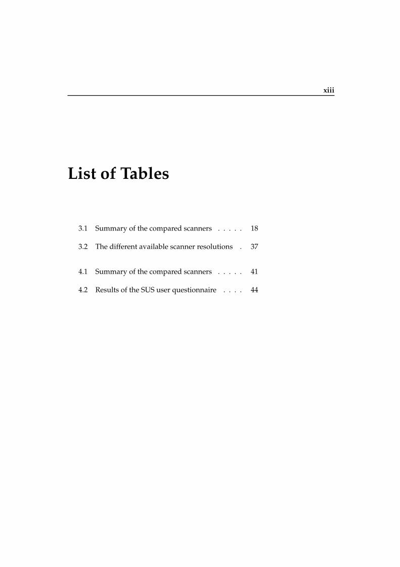
List of Tables
3.1 Summary of the compared scanners . . . . . 18
3.2 The different available scanner resolutions . 37
4.1 Summary of the compared scanners . . . . . 41
4.2 Results of the SUS user questionnaire . . . . 44

xv
Abstract
This thesis presents a hardware and software system for digitalizing the shape andcolor of physical objects under known environmental conditions.
The proposed system is conceived as a ”Do-It-Yourself 3D Laser Scanner”.Anyone with enough interest, can built his own FabScan 3D-Scanner. As such, theproject tries to support Gershenfeld’s vision of Personal Fabrication [Ger05].
The setup employs an ordinary webcam, an affordable line laser, two step-per motors and an Arduino Uno [Uno11]. The FabScan software is implementedusing OpenCV [BK08], the Powercrust algorithm [AC01], C++ and Objective-C.
The software is capable of mapping a colored point-cloud from the object,transforming the point-cloud into a surface-mesh and converting the surface-meshinto STL, which is a stereolithography file format used among others for 3Dprinting [FF11]. Post processing with additional software, such as MeshLab[CR08], is no longer needed.
I have discussed the challenges faced during the construction of the differentprototypes, the employed solutions and I am giving an evaluation of the finalprototype.
Finally, the reader is provided with detailed blueprints allowing the replica-tion of the complete system for less than 130e.

xvi Abstract

xvii
Uberblick
In dieser Arbeit beschreibe ich die Hard- und Software eines Systems das derDigitalisierung von Form und Farbe physikalischer Objekten unter bekannterUmgebung dient.
Das vorgestellte System ist als ”Do-It-Youself” Projekt gedacht. Jeder mitgenug Interesse, kann seine eigenen FabScan 3D-Scanner nachbauen. Somitunterstutzt das Projekt auch Gershenfelds Vision des Personal Fabrication [Ger05].
Der Aufbau basiert auf einer gewohnlichen Webcam, einem erschwinglichenLaser, zwei Schrittmotoren und einem Arduino Uno. Die FabScan Software istgeschrieben unter Benutzung von OpenCV[BK08], dem Powercrust Algorithmus[AC01], C++ und Objective-C.
Die Software kann farbige Punktwolken von Objekten erzeugen. Diese Punkt-wolken konnen in ein Oberflachen-Mesh umgewandelt werden und schliesslichals STL exportiert werden. STL ist ein stereolithisches Datei Format welches unteranderem beim 3D Drucken Anwendung findet. Dies macht die Weiterverarbeitungmit zusatzlicher Software, wie MeshLab, uberflussig.
Ich diskutiere die Herausforderungen mit denen ich wahrend der Konstruk-tion der verschiedenen Prototypen konfrontiert war, welche Losungen ich ge-funden habe und am Ende wird die Evaluierung des finalen Prototypen vorgestellt.
Schlussendlich werdem dem Leser eine ausfuhrliche Bauplane zum Nachbaudes kompletten Systems fur unter 130e bereit gestellt.


xix
Acknowledgements
At this place, I would like to thank Prof. Dr. Jan Borchers and Prof. Dr.-Ing.Kowalewski for giving me the possibility to do this work. Special thanks go to mysupervisor Rene Bohne and to Andre Stollenwerk for their constant support anduseful input. I also would like to thank all the people from the FabLab Aachenfor their constructive critique and all the people that took part in the user studies.Special thanks also to Mihir Joshi for checking the language and spelling of thisthesis.
Thank you!

xxi
Conventions
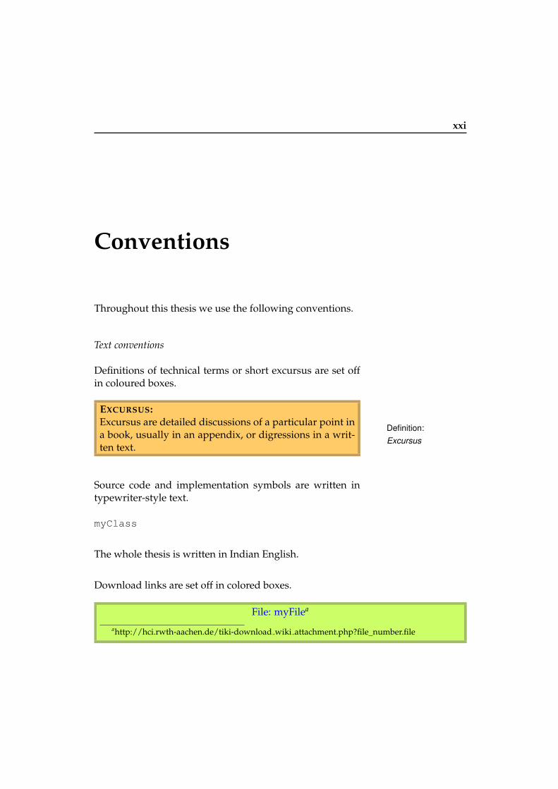
Throughout this thesis we use the following conventions.
Text conventions
Definitions of technical terms or short excursus are set offin coloured boxes.
EXCURSUS:Excursus are detailed discussions of a particular point ina book, usually in an appendix, or digressions in a writ-ten text.
Definition:Excursus
Source code and implementation symbols are written intypewriter-style text.
myClass
The whole thesis is written in Indian English.
Download links are set off in colored boxes.
File: myFilea
ahttp://hci.rwth-aachen.de/tiki-download wiki attachment.php?file number.file


1
Chapter 1
Introduction
“The next phase of the digital revolution will gobeyond personal computation to personal
fabrication.”
—Neil Gershenfeld
The digital revolution will be most successful whenpeople start organizing themselves into working groups[MLGG02]. This idea is realized by FabLabs all aroundthe world: Each FabLab consists of a collection of work-ing tools like laser-cutters, 3d-printers, milling machinesetc. which allow to design and prototype tools for a widerange of application fields. A FabLab is an open laboratory,which means it is not exclusively used by academics. Ev-ery amateur can use the equipment. Hence the aspect ofusability is of great importance.
The community can us these FabLabs to start ”creatingtheir own technological tools for finding solutions to theirown problems.”[MLGG02] Right now, the problem is thefollowing: people have to use highly professional model-ing software to create a digital representation of their ob-ject. Whereas sometimes it is way easier to use simple andknown tools (plaster for instance) to model an object. How-ever, this model needs to be digitalized so it can be furtherprocessed on the computer or even be shared among thecommunity.

2 1 Introduction
One solution to this problem are 3D scanners. A 3D scan-ner is a device that creates a digital model of a real worldobject by analyzing its shape and color. The field of ap-plication comprises computer graphics, robotics, industrialdesign, medical diagnosis, cultural heritage, multimedia,entertainment, as well as rapid prototyping and computer-aided quality control. [WMMW06] [LT09]
There is a variety of approaches to perform 3D scanning,including structured light, coded light, time of flight etc.[Bla04] The approach of choice for simple and precise 3Dscanning is triangulation-based laser range scanning whichconsists of calculating the intersection of the illuminat-ing laser beam and the rays projected back to the cam-era. [WMMW06] This technology is well-known for morethan twenty years [HMK82] [PM83]. In the last couple ofdecades, lasers and cameras have become inexpensive. 3Dscanners can now be built with off-the-shelf parts. [LT09]
Although a few non-professional 3D laser scanners al-ready exist, I will show in section 3.1—“Design and Re-quirements” that there is much room for improvement,especially on the software and usability side. I proposesuch a low-cost system for 3D data acquisition with in-tegrated surface-mesh generation and support for ready-to-print models. The provided software minimizes thepost-processing task which is cumbersome for most noviceusers. I will show that it is possible for untrained users toproduce a replica of an object with only a few clicks.
1.1 Thesis Overview
The thesis is organized as follows. In Chapter 2, I providean overview off different 3D scanning approaches. A set of3D scanners is presented and the math behind laser rangescanners is briefly explained. I give a few words on cam-era calibration and point-cloud to surface-mesh transfor-mations.Chapter 3 starts by listing the requirements for the project.Then I present my soft- and hardware prototypes. Eachprototype is accompanied by a short discussion.

1.1 Thesis Overview 3
In Chapter 4, the final prototype is evaluated. I show thatall the specified requirements were met. Both the usabilityof the complete setup and the precision of the scanner areanalyzed.The thesis concludes with a summary in chapter 5, fol-lowed by a quick look onto future work.

5
Chapter 2
Related work
This chapter starts by giving an overview of different 3Dscanning approaches, then I throw some light on a numberof available scanners. Later, the focus is put on camera cal-ibration and depth reconstruction from triangulation. Fi-nally, the generation of surface-meshes from point-cloudsis discussed.
2.1 3D Scanning Approaches
In this section, I will present a set of different 3D scanningapproaches. 3D scanning can be sub-divided into two maincategories: contact based and non-contact based.
2.1.1 Contact BasedContact basedscanners are slowand may harm theobject.
Contact based scanners are in direct contact with the sur-face of the object to be scanned. A probe is used to esti-mate the shape by recording the displacement of the probeas it slides across the solid surface. While effective, suchcontact-based methods can alter or even harm fragile ob-jects. Besides, they require long periods of time to build anaccurate 3D model. [LT09]
6 2 Related work
2.1.2 Non-contact BasedNon-contact basedscanners are fastand avoid damagingthe object.
Non-contact based scanners can further be sub-divided intopassive and active scanners. While both scanners rely onone or multiple light sources to reconstruct the shape ofthe object, passive scanners do not need to actively con-trol the illumination source, instead they rely entirely onambient light. Scanning without contact allows high speedscanning while avoiding physically damaging the object,which is important for instance while replicating antiques.[GSGC08]
Passive scanningStereoscopicimaging and thecorrespondenceproblem
The most famous representative of this technique is proba-bly stereoscopic imaging. In this approach, two cameras areused to mimic the human visual eye system. Knowing theposition of the cameras it is possible for each camera systemto independently establish an equation of a camera-ray (seesection 2.3.2—“Basics of Triangulation”) corresponding to apoint in space. By calculating the intersection of those re-sulting two camera-rays, the position of the specified pointcan be extracted. This concept can even be extended byadding more cameras. However, all such passive triangu-lation methods require correspondences to be found amongthe various camera views, which remains an open and chal-lenging problem [SRDD06], especially when scanning flator periodic textures. This problematic is known as the cor-respondence problem .Shape-from-
silhouette andshape-from-focus Many alternative passive methods emerged, avoiding the
correspondence problem. [A94] proposes a shape-from-silhouette algorithm. Another technique, shape-from-focus,uses the focus of the camera to recover depth. Only objectsclose to the plane of focus will appear in sharp contrast,whereas distant objects are blurred. [NN94] [WN98]

2.1 3D Scanning Approaches 7
Active ScanningSensitive to surfacematerial properties
Active optical scanners avoid the correspondence prob-lem by replacing one of the two cameras from stereoscopicimaging with a controlled illumination source, such as alaser or a projector. In comparison to non-contact and pas-sive methods, active illumination is often more sensitive tosurface material properties like reflection and absorption.[LT09] Laser range
scanners andstructured lightUsing a line laser, laser range scanners create a planar sheet
of light, which defines a plane in space. This plane of lightis then mechanically swept across the surface of the objectto be scanned. The depth is perceived by calculating the in-tersection of this plane with the set of lines passing throughthe laser reflection on the surface and the camera’s centerof projection. See section 2.3.2—“Basics of Triangulation”for further explanations and illustrations. A digital struc-tured light projector can be used to eliminate the mechani-cal motion required to translate the laser stripe across thesurface. The projector can display different patterns likemultiple lines at one time, which diminishes the scanningtime [SPSB04]. Problems: occluded
regions and dynamicscenesWhile effective, laser range scanners and structured light
scanner remain difficult to use if moving objects are presentin the scene. Due to the separation of the light source andthe camera, certain occluded regions cannot be recovered.This limitation require multiple scans to be merged, furtherincreasing the data acquisition time. Both laser range scan-ners and structured lighting are ill-suited for scanning dy-namic scenes. Time-of-flight
rangefinders
Another approach are time-of-flight rangefinders. They esti-mate the distance to a surface from a single center of projec-tion, so occluded regions do not appear. Since the speed oflight is known, it is possible to estimate the depth by mea-suring the elapsed time between emitting and receiving apulse of light. However, the depth resolution and accuracyof such systems remain below that of laser range scannersand structured lighting. [LT09]

8 2 Related work
2.2 Comparing Available 3D Scanners
Among all the presented scanning technologies, line-laserrange scanning offers the best combination of accuracy, af-fordability, scanning speed, and simplicity. This technol-ogy is also used by professional scanners such as the Artec3D Scanners1 and the NextEngine2 , whose prices start at10.900 e and 2.995 $ respectively. In this section I present alist of more affordable 3D scanners.
2.2.1 David Scanner
Figure 2.1: David Scanner
A starter kit of the David Scanner3 is available for 399 e.360� scans are possible, although the user needs to turn theobject manually between multiple scans. The software isproprietary and runs only on Windows. Minimal equip-ment is needed, such as a line laser, a camera and a calibra-tion pattern which can be printed out. Using the DAVID-Shapefusion software the user can manually merge multi-ple point-clouds from different scans and convert them to asurface mesh by-hand.
1http://www.artec3D.com/2http://www.nextengine.com/3http://www.david-laserscanner.com/
2.2 Comparing Available 3D Scanners 9
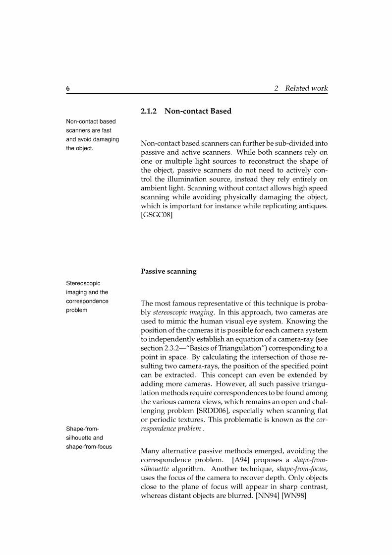
2.2.2 MakerBot 3D Scanner
Figure 2.2: Maker Bot 3D Scanner
The MakerBot 3D Scanner4 (formerly know as Cyclops) isa 3D scanning mounting kit for a pico projector, a webcamand an iPhone or iPod. The mounting kit is available for50$. A set of additional open-source software is required(ThreePhase, PeasyCam, ControlP5, Processing). Extensiveinstructions are provided on the website to perform a singleface scan. Using Blender and MeshLab the point-clouds aretransformed into surface meshes which can then be printedon the MakerBot.
2.2.3 3D Photography on your Desk
This project requires very little hardware: a camera, a desk-lamp, a pencil and a checkerboard.[BP98] The checker-board is used for calibration. The pencil is waved betweenthe lamp and the object to be scanned, casting a shadow onthe object. The 3D shape of the object is extracted from thespatial and temporal location of the observed shadow. Sev-eral implementations of this technique are available on theproject’s website5 .
4http://wiki.makerbot.com/3D-scanner5http://www.vision.caltech.edu/bouguetj/ICCV98/
10 2 Related work
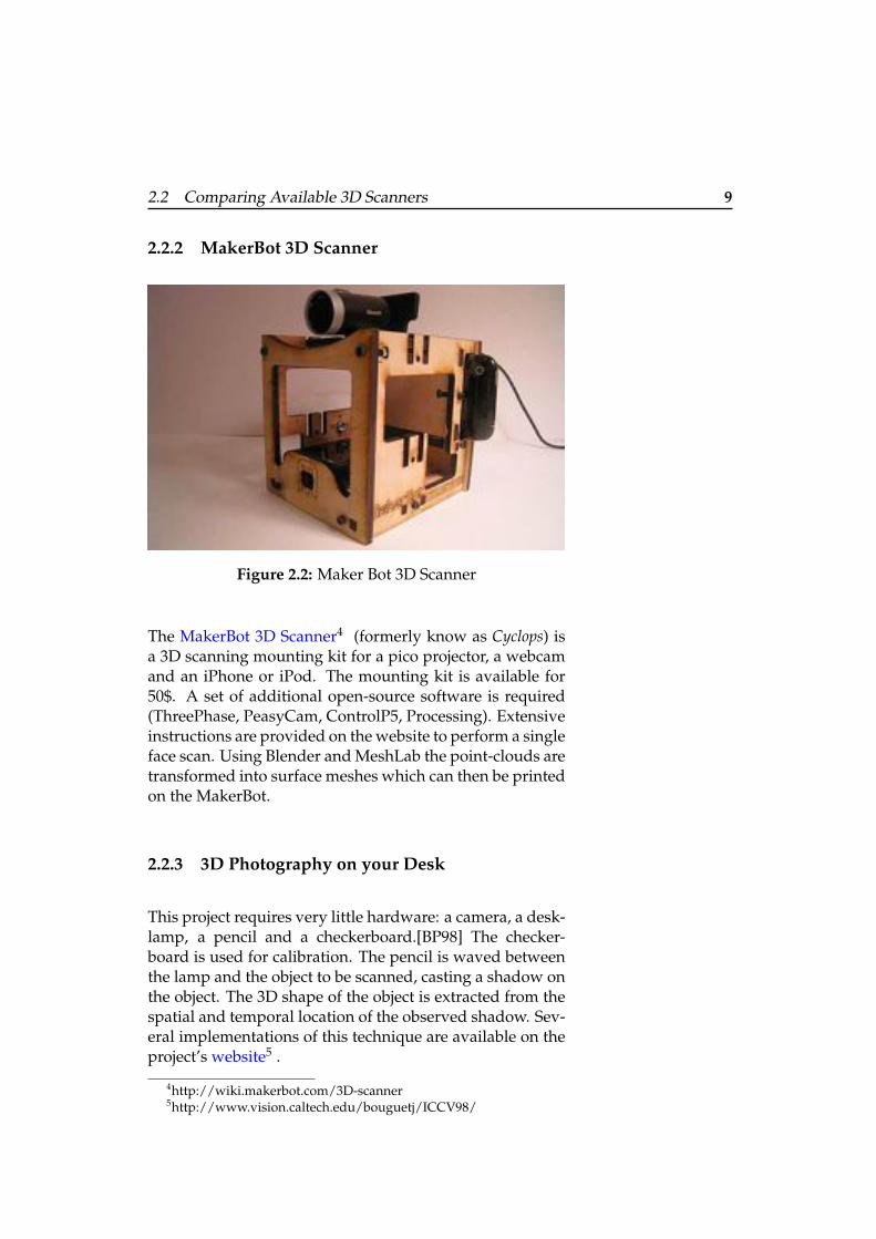
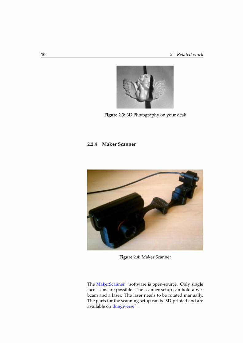
Figure 2.3: 3D Photography on your desk
2.2.4 Maker Scanner
Figure 2.4: Maker Scanner
The MakerScanner6 software is open-source. Only singleface scans are possible. The scanner setup can hold a we-bcam and a laser. The laser needs to be rotated manually.The parts for the scanning setup can be 3D-printed and areavailable on thingiverse7 .

2.3 Camera Calibration and Triangulation 11
2.2.5 Microsoft KinectThe Kinect is notsuited for 3DscanningIn 2011, Microsoft released the Kinect, a device for recog-
nizing and tracking player identity[LMW+11]. Besides aset of other sensors, the Kinect also includes infrared pro-jectors and cameras which are used for depth detection,hence it could also be used to build a 3D scanner. How-ever, according to [Rog11], the depth perception technol-ogy in the Kinect works best at distances of 6-8 feet (⇡ 2m).Thus, the Kinect is better suited for identifying ”likely hu-mans in the scene and the likely positions of their arms andlegs.”[Rog11] than for precise short-range 3D scanning.
2.3 Camera Calibration and Triangulation
In the previous section, a set of 3D scanners was intro-duced. In the next section, the thesis focuses on the theorybehind 3D laser range scanning. First, the pinhole cameramodel is introduced along with explanation about cameracalibration using functions provided by the Open ComputerVision Library (OpenCV) [BK08], then the basics of triangu-lation (used to recover the depth) are explained.
2.3.1 The pinhole camera model and camera cali-bration using OpenCV
In this model, exactly one light ray enters the camerathrough a pinhole from every point in the scene. The lightis ”projected” onto an image plane, behind the pinhole. Tosimplify the calculations, the pinhole camera is now rear-ranged: the image plane is put in front of the pinhole whichis now reinterpreted as the center of projection. The dis-tance between the center of projection and the image planeis known as the focal length f. Figure 2.5 shows the rear-ranged pinhole camera model setup.
6http://wiki.makerbot.com/makerscanner7www.thingiverse.com

12 2 Related work
Center ofprojection
Image plane
f
Figure 2.5: The pinhole camera model
Intrinsic properties
Notice that there are actually two focal length parametersf
x
and f
y
. The reason for this is that the individual pix-els on a typical low-cost camera are rectangular rather thansquare. Furthermore, the center of the chip is usually notaligned with the optical axis. Thus, two new parameters,c
x
and c
y
, are introduced to model a possible displacement(away from the optic axis) of the projection screen.
These parameters f
x
, fy
, cx
and c
y
are known as the intrinsicproperties.
Lens distortions
In theory, a lens can be defined without distortions. Inpractice, however, no lens is perfect. There are two non-negligible types of distortion: Radial distortions (”fish-eye”effect) arise as a result of the shape of lens, whereas tangen-tial distortions arise from the lens not being exactly parallelto the image plane. (Compare chapter 3 of [LT09]). Radialdistortions are represented by at least three parameters k1,k2 and k3. Even more parameters can be introduced forcameras with higher radial distortion. Tangential distor-tion is characterized by two additional parameters, p1 andp2. All these parameters are explained in detail in chapter11 of the OpenCV book [BK08].

2.3 Camera Calibration and Triangulation 13
Extrinsic properties
The parameters R and T , which are referred to as the ex-trinsic parameters of the camera, describe the location andorientation of the camera in world coordinates. In three-dimensional space each of them can be represented as athree-dimensional vector, which gives us a total of 6 extrin-sic parameters.
The OpenCV method cvCalibrateCamera2(), explained onpage 398 of the OpenCV book, can be used to calculate theintrinsics, the distortion and the extrinsic parameters. Asinput, the function uses pictures of several chessboard pat-terns as explained in [Zha00]. OpenCV’s approach to calcu-late the intrinsics is derived from [HS97]. Both [XRL11] and[WLZ10] deal with camera calibration techniques based onOpenCV.
2.3.2 Basics of Triangulation
In this section, the concept of triangulation is explained.Giving a complete and detailed insight into this topicwould go beyond the scope of this thesis. Therefore, I onlyintroduce the basic concepts of triangulation. For the inter-ested reader, I suggest reading chapter 2 The Mathematics ofTriangulation of [LT09].
Every piece of hardware used in the scanner is representedby a model in the software. For the camera, the Camera Pin-hole model is used as explained in section 2.3.1—“The pin-hole camera model and camera calibration using OpenCV”.Figure 2.6 shows the basic model used for triangulation.
The line laser can be modeled as a simple plane in space, as-suming the opening angle of the laser lens is large enoughand the laser is placed sufficiently far away from the object.
The intersection of the laser light plane with the object be-ing scanned generally contains many illuminated curvedsegments (see Figure 2.6 red curved line). These segmentsare composed of many illuminated points. A single illu-

14 2 Related work
Center ofProjection
Laser Light PlaneObject being
scanned
Intersection the ofLaser Light Planewith the ObjectCamera Ray
Line LaserImage Plane
Figure 2.6: Model of 3D surface recovery using ray-plane-intersection triangula-tion.
minated point, visible to the camera, defines a camera ray.Here, it is assumed that the positions and rotations of thelaser and the camera are known with respect to the globalcoordinate system. In the previous section it is explainedhow to estimate these values for the camera. Under thisassumption, the equations of the laser light plane, as wellas the equations of camera rays corresponding to illumi-nated points, can be calculated. The location of the illu-minated points can be recovered by intersecting the laserlight plane with the camera rays corresponding to the illu-minated points. By rotating the object (and the laser) dur-ing the scan, all sides of the object are illuminated, allowingrecovery of a 360� surface model. [LT09]
2.4 Surfaces from Point-Clouds
As soon as a point-cloud is acquired, it enters the post-processing pipeline whose eventual goal is to produce apolygon surface mesh, which can then be used for 3D print-ing.Powercrust
The powercrust algorithm [AC01] can be used for this task:”The power crust is a construction which takes a sample ofpoints from the surface of a three-dimensional object andproduces a surface mesh.” The algorithm delivers a wa-tertight surface-mesh and eliminates the polygonization,hole-filling or manifold extraction post-processing steps re-

2.4 Surfaces from Point-Clouds 15
quired in other surface reconstruction algorithms, which isideal for our needs. Besides providing an implementationof the algorithm, the authors also prove ”good empirical re-sults on inputs including models with sharp corners, sparseand unevenly distributed point samples, holes, and noise,both natural and synthetic”.
Figure 2.7: ”Laser range data, the reconstructed watertightpolygonal model, and its simplified medial axis.” [AC01]
Point Cloud Libraryand OpenNI
Alternatively, one can refer to the Point Cloud Library (PCL)[RC11] presented in 2011. The library contains state-of-theart algorithms for filtering, feature estimation, surface re-construction, registration, model fitting and segmentation.Furthermore, it offers native support for OpenNI [Ope11]3D interfaces, and can thus acquire and process data fromdevices supporting this standard, such as the MicrosoftKinect.


17
Chapter 3
Own work
The previous chapter introduced the concept of 3D scan-ning. A number of DIY 3D scanners were presented. In thefollowing chapter I will present the design, the software aswell as the hardware prototypes of the FabScan 3D scanner.
3.1 Design and Requirements
This project rooted in the idea to supply the FabLabAachen1 with a low-cost 3D scanner. In an initial userstudy, I surveyed people visiting the FabLab about 3D scan-ners. The following requirements of the scanner were iden-tified:
• Affordability The scanner should be affordable, to anextend that amateurs with a modest budget can pur-chase it.
• Ready-To-Print The scanning software should makeit easy for the user to produce a watertight ready-to-print surface meshes of the scanned object. Thus,eliminating, or at least minimizing, the cumbersomepost-processing pipeline.
1http://fablab.rwth-aachen.de

18 3 Own work
• Do-It-Yourself Anyone should be able to assemblethe scanner with access to a laser-cutter, 3D printer,soldering iron, etc. The parts of the scanner couldeven be provided as an inexpensive construction kit.
• 360�-Scan The scanner should be able to automati-cally scan the object from all viewing angles in onlyone scan, without requiring the user to manually ro-tate the object.
• Portability The software should be portable to multi-ple platforms or at least run on a Mac as the FabLabAachen is based on Macs.
• Usability Untrained users should be able to copewith the system. Ideally, the scanning process shouldbe fully automatic. The user should only need topress a button once to start a scan.
3.1.1 Comparing Scanners
The following table summaries the scanners presented inchapter 2. They are compared to the previously establishedrequirements.
Affo
rdab
ility
Read
y-To
-Prin
t
Do-
It-Yo
urse
lf
360�
-Sca
n
Port
abili
ty
Usa
bilit
y
DAVID Scanner 4 4 4 4 8 4MakerBot 3D Scanner 4 8 4 8 4 8
3D Photography on your desk 4 8 4 8 4 8Maker Scanner 4 8 4 8 4 8
Table 3.1: Summary of the compared scanners
It should be noted that ”usability is not a quality that existsin any real or absolute sense” [Bro11]. Here usability is sim-ply defined wether it is possible to perform a scan using avery reduced number of clicks or not.

3.2 Hardware Prototypes 19
Figure 3.1: Physical objects used for prototype testing. From left to right: the bear,the skull, the duck and the cup.
3.2 Hardware Prototypes
The final hardware prototype is the result of severalDIA-cycle iterations (Design Implement Analyze) [Car92][Bor01]. In this section, I present all the prototype itera-tions. I show some of the scanning results of each proto-type and shortly discuss what I learned from the prototypeand how I used this information to improve the next proto-type. Throughout the prototyping phase, I experimentedwith several objects of different size, material, color andshape. In the following, I will refer to those objects withthe names as presented in the caption of figure 3.1.
3.2.1 First Hardware Prototype
The first prototype is based on the Maker-Scanner, pre-sented in section 2.2.4—“Maker Scanner”. The scanningsetup is composed of four primary items: a Logitech Quick-cam Pro 9000 webcam, a line laser on a servo motor, anArduino Uno[Uno11] and two planar surfaces. Note thatthe laser and webcam must be separated so that the laserlight plane and camera rays do not meet at small incidenceangles, otherwise triangulation will result in large errors.[LT09] On the other side, the angle must not be too largeto avoid obscured areas on the surface of the object. Thetwo planes should form a right angle. The setup differsin one major point form the Maker-Scanner: whereas thelaser of the Maker scanner is swept manually by the user,

20 3 Own work
this prototype incorporates a servo motor which takes overthe role of the user moving the laser. This allows a fullyautomatic scan, hence the user is not involved in the ac-tual scanning process. This point is important as the usershould not need to interact with the system during a scan.The servo motor is controlled using an Arduino, which isconnected to the computer over a serial port. The Arduinois also used to turn the laser on and off. This is used toextract a hight contrast image of the laser line (comparewith section 3.5.1—“Laser Threshold”). The setup of thefirst prototype is shown in figure 3.2.
Figure 3.2: Setup of the first prototype.
Discussion
The first prototype showed that the triangulation principlegives acceptable results, even when using a rather simplesetup. The result of a scan is shown in figure 3.3. Onevertical line corresponds to one laser position. The rela-tively large gap between the different lines is due to theused servo: the minimal resolution of the servo is 1� perstep. Also, it is not possible to get a full 360� scan of theobject.

3.2 Hardware Prototypes 21
Figure 3.3: Scanning results from first prototype. Left: thephysical object Bear. Right: the point-cloud of the Bear
The ambient light has a great influence on the scanningresults. Ambient illumination must be reduced so thatthe laser line is clearly visible to the camera. However, itshould also not be too dark to allow the camera to operatewith minimal gain. Otherwise sensor noise will corrupt thereconstruction. The mentioned ”3D Photography on yourdesk” scanner has the same problem [BP98].
3.2.2 Second Hardware Prototype
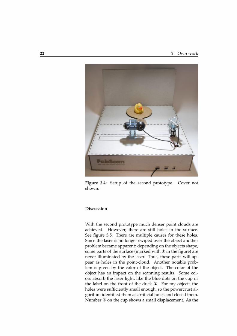
To get a full 360� scan of the object the laser is no longerswept over the object but instead the object is placed ona turntable. The turntable is mounted on a stepper motorwhich allows it to turn. The stepper motor can make stepsas small as 0.1125� (see also 3.4.2—“Selecting the scanningresolution”), which is largely sufficient for our purpose.The servo is no longer used during the scanning process,it only serves as a nice holder for the laser. Also I createda box for the scanner. The Arduino is now mounted in-side the box and all the cables can easily be plugged intothe front of the box. The scanner is now more portable andless time is needed to set it up. Later, I also created a coverwhich can be placed on top of the scanner to isolate it fromambient illumination. The setup is depicted in figure 3.4.
22 3 Own work
Figure 3.4: Setup of the second prototype. Cover notshown.
Discussion
With the second prototype much denser point clouds areachieved. However, there are still holes in the surface.See figure 3.5. There are multiple causes for these holes.Since the laser is no longer swiped over the object anotherproblem became apparent: depending on the objects shape,some parts of the surface (marked with ¨ in the figure) arenever illuminated by the laser. Thus, these parts will ap-pear as holes in the point-cloud. Another notable prob-lem is given by the color of the object. The color of theobject has an impact on the scanning results. Some col-ors absorb the laser light, like the blue dots on the cup orthe label on the front of the duck ≠. For my objects theholes were sufficiently small enough, so the powercrust al-gorithm identified them as artificial holes and closed them.Number Æ on the cup shows a small displacement. As the

3.2 Hardware Prototypes 23
1
112
3
3
4
22
1
Figure 3.5: Point clouds generated with the second prototype from various pointof views. Left: the cup. Right: the duck
material of the cup is slippery, it moved a little during thescanning process every time the turntable advanced a step.This can be solved by placing a round piece of black fabriconto the turntable which augments the grip. In addition,the black color of the fabric absorbs unwanted reflectionsof the laser line on the turntable. The material of the duckis less slippery, so it did not move during the scan. Never-theless, one can notice slightly different colors. This is dueto a different illumination between the start and end of thescan. This problem is eliminated by putting a cover on topof the scanner and adding a light source under the scannerso the illumination conditions stay the same during a scan.One could think that the light source is unnecessary if col-ored point clouds are not needed. Yet putting the object incomplete darkness, with the laser as the only light source,makes it difficult for the camera’s built-in auto focus featureto take sharp pictures. The strange displacement markedwith Ø near the top of the ducks head was due to a softwarebug, which is fixed now. On a more general note, with thecurrent setup where the object is rotated on only one axe,it is not possible to scan the bottom of the objects, nor theinside of the cup or the top of the ducks head Ø.
On the hardware side, the design of the box is not ideal: TheArduino is not easily accessible and the material of the boxwears out when opening the box to often. The connectorsare also not well placed. In most cases, the computer whichcontrols the scanner is placed either on the left or the rightof the scanner, so should be the connectors.

24 3 Own work
3.2.3 Third Hardware Prototype
Figure 3.6: Setup of the third prototype
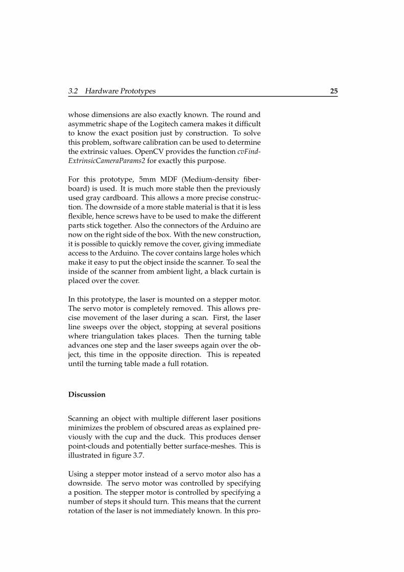
From the last prototype, I learned several points: The scan-ner should be easier to assemble and disassemble withoutdestroying the material. The laser needs to rotate duringa scan in order to cover more parts of the object surface.Since the servo motor is not precise enough, it should bereplaced by a stepper motor. The construction by itselfshould allow to deduce the exact position of the laser rel-ative to the turntable. Another, more stable and enduringmaterial should be used.
The main idea behind the construction of this prototype isto fix all the critical parts, like the camera, the laser and theturntable on one single base plane. This single base planecan then be used as a very precise reference system whichallows to deduce the exact positions of the turntable andthe laser as those are both positioned on a stepper motor,
3.2 Hardware Prototypes 25
whose dimensions are also exactly known. The round andasymmetric shape of the Logitech camera makes it difficultto know the exact position just by construction. To solvethis problem, software calibration can be used to determinethe extrinsic values. OpenCV provides the function cvFind-ExtrinsicCameraParams2 for exactly this purpose.
For this prototype, 5mm MDF (Medium-density fiber-board) is used. It is much more stable then the previouslyused gray cardboard. This allows a more precise construc-tion. The downside of a more stable material is that it is lessflexible, hence screws have to be used to make the differentparts stick together. Also the connectors of the Arduino arenow on the right side of the box. With the new construction,it is possible to quickly remove the cover, giving immediateaccess to the Arduino. The cover contains large holes whichmake it easy to put the object inside the scanner. To seal theinside of the scanner from ambient light, a black curtain isplaced over the cover.
In this prototype, the laser is mounted on a stepper motor.The servo motor is completely removed. This allows pre-cise movement of the laser during a scan. First, the laserline sweeps over the object, stopping at several positionswhere triangulation takes places. Then the turning tableadvances one step and the laser sweeps again over the ob-ject, this time in the opposite direction. This is repeateduntil the turning table made a full rotation.
Discussion
Scanning an object with multiple different laser positionsminimizes the problem of obscured areas as explained pre-viously with the cup and the duck. This produces denserpoint-clouds and potentially better surface-meshes. This isillustrated in figure 3.7.
Using a stepper motor instead of a servo motor also has adownside. The servo motor was controlled by specifyinga position. The stepper motor is controlled by specifying anumber of steps it should turn. This means that the currentrotation of the laser is not immediately known. In this pro-

26 3 Own work
Figure 3.7: Surface meshes of the cup. The handle ofthe cup dramatically increases in quality when using morelaser positions. Left: 1 single laser position. Middle: 3 dif-ferent laser positions. Right: 5 different laser positions.
totype, it is assumed that the laser is pointing at a specificposition (marked on the box) before every scan. If this isnot the case, the user is required to manually turn the laserto that position. To overcome this cumbersome situation,one could either use additional hardware such as an endswitch or a potentiometer, alternatively the position couldbe deduced using software calibration.
The idea to put to camera, the laser and the turntable on onesingle reference plane worked very well. Unfortunately,OpenCVs cvFindExtrinsicCameraParams2 did not provideuseful values for the extrinsic parameters. Using the olderOpenCV Framework 1.2 available from the RWTH IENT in-stitute2 improved the situation a little: although the cvFind-ExtrinsicCameraParams2 still did not work as hoped, thefunction cvCalibrateCamera2 at least delivered more realis-tic values for the extrinsics but still not precise enough. Thereason for this is most probably a bug in either my softwareor the implementation of OpenCV. Since the position of thecamera is a crucial part of triangulation and time was mov-ing on, I decided not to use OpenCV but instead measurethe extrinsic values physically. Obviously, this situation isnot ideal.
The turntable is a critical part of the scanner. Its mechanicalconstruction has a great influence on the scanning results.The turning table should be perfectly horizontal and turn inone single plane. Also the surface of the turntable should beragged otherwise the object might slip when turning. Thisresults in a distorted image as the software thinks the objecthas rotated but in fact it has not or only a little.
2http://www.ient.rwth-aachen.de/cms/opencv/

3.2 Hardware Prototypes 27
An important aspect is the time it takes for a scan to com-plete. As explained in the section 3.5.1—“Laser Threshold”two pictures are taken every time the turntables moves.The camera takes some time to focus when the imagechanges, so it takes some time until the image is stable. Thistime could dramatically be shortened when disabling somefeatures on the camera like auto-exposure-time and auto-white-balance. Since the camera supports the UVC [For05]standard, this features can be turned off. I already havesome working code, which does exactly this but it is notyet implemented in the this version of the prototype.
3.2.4 PCB - Arduino Shield
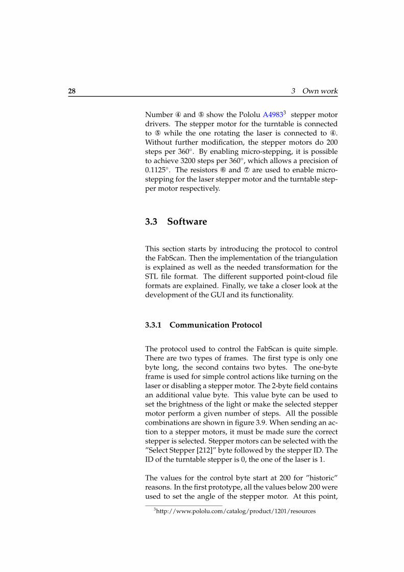
To control the two stepper motors, the laser and the LEDs Iam using an Arduino with an additional self-made shield.The Arduino and both sides of the shield are shown in fig-ure 3.8. The shield was manufactured on a CNC millingmachine. It is simply plugged on top of the Arduino.
The maximum voltage for the laser is 4,5V. A diode is usedto go from the 5V, provided by the Arduino, down to 4,3V.The laser is connected to ¨, as shown in figure 3.8. TheLEDs are connected to ≠. The power supply for the LEDsis controlled with a transistor Æ. The transistor is attachedto a PWM capable pin on the Arduino so it is possible toprecisely set the brightness of the LEDs.
2
6
7
34
5
1
Figure 3.8: Left: Arduino Uno. Middle: Front side of shield.Right: Back side of shield
28 3 Own work
Number Ø and ∞ show the Pololu A49833 stepper motordrivers. The stepper motor for the turntable is connectedto ∞ while the one rotating the laser is connected to Ø.Without further modification, the stepper motors do 200steps per 360�. By enabling micro-stepping, it is possibleto achieve 3200 steps per 360�, which allows a precision of0.1125�. The resistors ± and ≤ are used to enable micro-stepping for the laser stepper motor and the turntable step-per motor respectively.
3.3 Software
This section starts by introducing the protocol to controlthe FabScan. Then the implementation of the triangulationis explained as well as the needed transformation for theSTL file format. The different supported point-cloud fileformats are explained. Finally, we take a closer look at thedevelopment of the GUI and its functionality.
3.3.1 Communication Protocol
The protocol used to control the FabScan is quite simple.There are two types of frames. The first type is only onebyte long, the second contains two bytes. The one-byteframe is used for simple control actions like turning on thelaser or disabling a stepper motor. The 2-byte field containsan additional value byte. This value byte can be used toset the brightness of the light or make the selected steppermotor perform a given number of steps. All the possiblecombinations are shown in figure 3.9. When sending an ac-tion to a stepper motors, it must be made sure the correctstepper is selected. Stepper motors can be selected with the”Select Stepper [212]” byte followed by the stepper ID. TheID of the turntable stepper is 0, the one of the laser is 1.
The values for the control byte start at 200 for ”historic”reasons. In the first prototype, all the values below 200 wereused to set the angle of the stepper motor. At this point,
3http://www.pololu.com/catalog/product/1201/resources

3.3 Software 29
Turn Laser Off [200]
Turn Laser On [201]
Perform Step [202]Turn Stepper On [205]
Turn Stepper Off [206]
Set Direction CW [203]
Set Direction CCW [204]
Select Stepper [212]
FabScan Ping [210]
Turn Light Off [208] Turn Light On [207] Light Intensity [0..255]
Stepper ID [0..1]
Turn Table Steps [0..255]
Figure 3.9: FabScan Communication Protocol. The value or the range for each byteis specified in brackets. Left and Middle: single byte frames. Right: dual byteframes
since the servo motor is no longer used, they could just aswell start at 0.
To make sure that there is actually a FabScan connected tothe selected serial port, and not some other device whichhappens to have a serial port running, a ”FabScan Ping[210]” message is sent, which needs to be answered with a”FabScan Pong [211]”. When answered correctly, it is clearthat a FabScan is connected to that serial port.
The computer talks to the FabScan over serial communi-cation. On the Arduino side, the standard Serial Library isused. On the Mac, the class FSSerial is responsible for se-rial communication. It is based on Apple’s IOKit and theexample provided on the Arduino page4
3.3.2 Implementing Triangulation
For 3D depth recovery, I use line-ray triangulation as ex-plained in section 2.3.2—“Basics of Triangulation”. Due tothe known geometry of the hardware it is possible to sim-plify the model without losing to much precision. The fol-lowing assumptions are made:
• The laser line is perfectly vertical.
• The camera is pointed perfectly straight and perpen-dicular to the back of the box.
4http://www.arduino.cc/playground/Interfacing/Cocoa

30 3 Own work
The error introduced by these assumptions is relativelysmall and it simplifies the math. The position of the laserand the camera are known by construction. Also the posi-tion of the laser line hitting the back of the box is known,since the rotation and position of the laser are known. Nowthe laser line is extracted from the camera picture as ex-plained in section 3.5.1—“Laser Threshold”. The positionsof the reflected points on the surface of the object are trans-formed from the image plane coordinate system into theworld coordinate system. By making use of the previousassumptions, all these points can be projected onto one hor-izontal plane, allowing us to move from 3D into 2D. Thissituation is depicted in 3.10. This simplification implies theloss of the hight information, but it can be reintroduced aswe will see later. We simplified the 3D line-plane intersec-
Image Plane
Camera Laser
Box
x
yp1
p2 l1
l2
I
Figure 3.10: 2D line-line intersection
tion problem to the easier 2D line-line intersection problem.
Using two known points p1 and p2, we can establish theequation of a line l1. Generally, the equation of a 2D line isgiven by:
y = a · x + b (3.1)
Points are represented as a tuple p = (xp
, y
p
). Specifically,the equation for l1 is given by:
l1 ⌘ y = a1 · x + b1 (3.2)
where a1 can be expressed depending on p1 and p2:
a1 =�y
�x
=y
p2 � y
p1
x
p2 � x
p1(3.3)

3.3 Software 31
Inserting p1 (or p2) into (3.2) and solving for b1 gives us:
b1 = y
p1 � a1 · xp1 (3.4)
At this point we have the complete equation for l1. We usethe same procedure to calculate l2. Knowing the equationsof two lines l1 and l2 we can calculate their intersection I.
l1 = l2 (3.5), a1 · xI + b1 = a2 · xI + b2 (3.6)
, xI =b2 � b1
a1 � a2(3.7)
with a1 6= a2 (3.8)
Again, yI can be calculated inserting I into (3.2):
yI = a1 · xI + b1 (3.9)
Now the depth in real world coordinated of the scannedpoint is known, hence we can simply scale the height whichis in image plane coordinates to get the world coordinateswhich gives us the 3D representation of the scanned point.These calculations are repeated for every point on the re-flected laser line on the surface of the object. This set ofpoints still needs to be rotated using affine transformationsin order to take the rotation of the turntable into account.
3.3.3 From Point-Clouds to Printable Files
As soon as a point-cloud is acquired, it enters post process-ing whose eventual goal is to produce a polygon surface-mesh which can be used for 3D printing. Transformingthe point-cloud into a polygon surface mesh is done us-ing the powercrust algorithm as presented in section 2.4—“Surfaces from Point-Clouds”.
We want to export the model into STL which is a stere-olithography file format used among others for 3D print-ing. The format is shortly defined below:

32 3 Own work
STL FILE FORMAT:”An STL file is a triangular representation of a 3D surfacegeometry. [...] The native STL format has to fulfill thefollowing specifications: (i) The normal and each vertexof every facet are specified by three coordinates each, sothere is a total of 12 numbers stored for each facet. (ii)Each facet is part of the boundary between the interiorand the exterior of the object. The orientation of the facets(which way is “out” and which way is “in”) is speci-fied redundantly in two ways which must be consistent.First, the direction of the normal is outward. Second, thevertices are listed in counterclockwise order when look-ing at the object from the outside (right-hand rule). (iii)Each triangle must share two vertices with each of its ad-jacent triangles. This is known as vertex-to-vertex rule.(iv) The object represented must be located in the all-positive octant (all vertex coordinates must be positive).” [FF11]
Definition:STL File Format
The powercrust faces are not triangles. Thus, the poly-gons need to be transformed into triangles and the normalsneed to be calculated. This is done by taking the first threevertices of every face and combining them to a new face.This procedure is repeated for all the remaining vertices.However, this approach can create faces with small angles.Small angles add errors when trigonometric functions areapplied on them.
The normal n of a flat face with the vertices v1, v2 and v3 isdefined by the cross product:
n = (v1 � v2)⇥ (v2 � v3) (3.10)
The normal n still needs to be normalized by dividing everycomponent of the vector with the vectors length l:
l =p
x
2n
+ y
2n
+ z
2n
(3.11)
Now all the data for the STL file is known.
A ASCII STL file starts with solid and ends withendsolid. In between, all the faces are listed, as shownbelow:

3.3 Software 33
facet normal n
x
n
y
n
z
outer loop
vertex v1x
v1y
v1z
vertex v2x
v2y
v2z
vertex v3x
v3y
v3z
endloop
endfacet
3.3.4 Point-Cloud File Formats
Besides exporting the surface-mesh of the scanned model,it is also possible to export the point-cloud itself. The soft-ware supports three different point-cloud file formats: PTS,PLY and PCD.
PTS
The PTS file format is very basic. Every line corresponds toone point in the cloud. Each line contains only the positionof the point, it has the format x y z. The file has no headernor footer.
PLY
The PLY file format is supported so the point-clouds can beopened in MeshLab. Although the format can be used tostore polygons, here only the point-cloud part is supported.Similar to the PTS format, every line corresponds to a point.In addition to the position, a line also contains the colorinformation. The format is x y z r g b. The type foreach field is defined in the header. A full documentation ofthe file format is provided here5 .
5http://paulbourke.net/dataformats/ply/

34 3 Own work
PCD
The Point Cloud Data (PCD) file format is part of PCL, seesection 2.4—“Surfaces from Point-Clouds”. PCD is also thenative file format in FabScan, which means it is the de-fault format for saving point-clouds. PCD files can also beopened with FabScan. A full documentation of the file for-mat, along with an extensive motivation for yet another fileformat is provided at the PCL Documentation6 .
3.4 GUI and Functionality
In this section, I shortly present the different GUI proto-types. Then the basic as well as the advanced functions ofthe software are explained.
3.4.1 User Interface Prototypes
The graphic user interface of FabScan is largely inspired byApple’s Photo Booth7 as the concept of taking a picture orrecording a video is somewhat similar to performing a 3Dscan. See figure 3.12 for a comparison of PhotoBooth andthe final user interface design.
The first user interface prototype was a paper prototype.Paper prototypes are quick and cheap to develop. They arenot detailed, so the designer and the user can focus on im-portant high-level user interface design development. Ad-ditionally, they can quickly be changed to reflect the usersinput.
The user studies with this paper prototype have shown thatthe concept of making it similar to a known software (Pho-toBooth) helped to quickly understand the GUI elements.The idea of pressing the scan button in order to start a scanbecame clear instantly. Further studies have shown that the
6http://pointclouds.org/documentation/tutorials/pcd file format.php7http://www.apple.com/macosx/apps/#photobooth

3.4 GUI and Functionality 35
- + FabScan
Scan
Figure 3.11: First paper prototype
Figure 3.12: FabScan compared to Photo Booth. Left: Photo Booth. Right: FabScan
36 3 Own work
panel on the bottom of the window showing previous scansis not really needed. Hence, it was elided from the follow-ing prototypes.
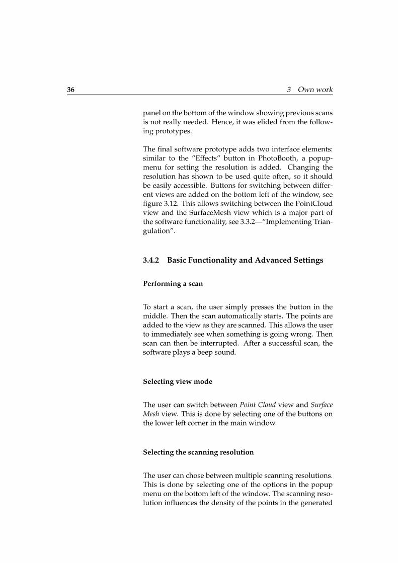
The final software prototype adds two interface elements:similar to the ”Effects” button in PhotoBooth, a popup-menu for setting the resolution is added. Changing theresolution has shown to be used quite often, so it shouldbe easily accessible. Buttons for switching between differ-ent views are added on the bottom left of the window, seefigure 3.12. This allows switching between the PointCloudview and the SurfaceMesh view which is a major part ofthe software functionality, see 3.3.2—“Implementing Trian-gulation”.
3.4.2 Basic Functionality and Advanced Settings
Performing a scan
To start a scan, the user simply presses the button in themiddle. Then the scan automatically starts. The points areadded to the view as they are scanned. This allows the userto immediately see when something is going wrong. Thenscan can then be interrupted. After a successful scan, thesoftware plays a beep sound.
Selecting view mode
The user can switch between Point Cloud view and SurfaceMesh view. This is done by selecting one of the buttons onthe lower left corner in the main window.
Selecting the scanning resolution
The user can chose between multiple scanning resolutions.This is done by selecting one of the options in the popupmenu on the bottom left of the window. The scanning reso-lution influences the density of the points in the generated
3.5 Better Scanning Results 37
point-cloud. A higher scanning resolution means morepoints but also a longer scanning time. When scanning anew object, it is recommended to start with a quick low res-olution scan in order to verify if the resulting point-cloud isacceptable. Some objects depending on there material, size,surface and color may not be well suited for scanning. Seealso section 3.5—“Better Scanning Results”.
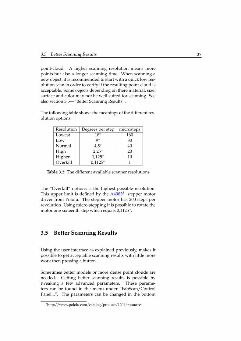
The following table shows the meanings of the different res-olution options.
Resolution Degrees per step microstepsLowest 18� 160Low 9� 80Normal 4,5� 40High 2,25� 20Higher 1,125� 10Overkill 0,1125� 1
Table 3.2: The different available scanner resolutions
The ”Overkill” options is the highest possible resolution.This upper limit is defined by the A49838 stepper motordriver from Pololu. The stepper motor has 200 steps perrevolution. Using micro-stepping it is possible to rotate themotor one sixteenth step which equals 0,1125�.
3.5 Better Scanning Results
Using the user interface as explained previously, makes itpossible to get acceptable scanning results with little morework then pressing a button.
Sometimes better models or more dense point clouds areneeded. Getting better scanning results is possible bytweaking a few advanced parameters. These parame-ters can be found in the menu under ”FabScan/ControlPanel...”. The parameters can be changed in the bottom
8http://www.pololu.com/catalog/product/1201/resources

38 3 Own work
part of the Control Panel window. In the following theseparameters are explained.
Setting the stepper motors resolution
The first parameter defines how many micro-steps theturntable turns in each step. By setting a lower value, thepoint-cloud becomes more dense, but the scanning takesmore time. The second parameter specifies how many sam-ples should be taken from the scanned lines. This is usefulto get nice quadratic polygons, depending on the first pa-rameter.
The next parameters influence the laser stepper motor. The”Laser steps” defines the number of different laser posi-tions between each step of the turntable. The angle betweenthe laser steps can be adjusted with the next parameter. Ahigher number of laser steps means less occluded areas onthe objects surface, which leads to less artificial holes in thepoint-cloud. The scanning time is directly proportional tothe number of laser steps.
3.5.1 Laser Threshold
For each step of the scanning process we extract the laserline. This is done by taking a picture when the laser is onand one when it is off. These color pictures are transformedinto grayscale. Then the absolute difference between eachpixel of the two pictures is calculated. If the difference ishigher then the ”Laser Threshold” value, the pixel belongsto the laser line. This procedure produces a very high con-trast line line.
You should change the threshold value, if the points on thescanned line are not aligned or when they differ too muchin the depth. The threshold value should always be as highas possible. If it is too high, no points will appear duringthe scan.

3.5 Better Scanning Results 39
Moreover, the laser line has a certain width. The rightand the left limit of the laser line can be determined inthe camera picture. The exact position of the laser linecorresponds to the average value of those two lines. Theselimits are determined in pixels. When transforming theminto world coordinates and then calculating the averagevalue, it is possible to get sub-pixel accuracy. This is notyet implemented in the current software prototype.
3.5.2 Lower Limit
Sometimes points from the surface of the turntable are un-intentionally scanned or the scanned object is positioned ona basement that should not be included in the model. Set-ting the ”Lower Limit” allows to elide all the scanned pixelsbelow this value.


41
Chapter 4
Evaluation
In this section, I verify wether all the initial requirementsas described in 3.1—“Design and Requirements” are met.Additionally the precision of the scanner is evaluated byscanning known reference objects and comparing them tothe scanned results.
4.1 Affordability
In this paragraph we first calculate the price of the currentprototype. The user studies, presented in 4.5—“User Stud-ies”, showed that most people think the price is appropri-ated. The following table shows a price listing 1 :
Component Count Price SumStepper motor 2 12,93 e 25,86 e
Pololu stepper motor driver 2 9,5 e 19,00 eArduino Uno 1 25,80 e 25,80 e
Red Line Laser 1 2,4 e 2,4 eLogitech QuickCam Pro 9000 1 49,99 e 49,99 e
MDF + Screws + Nuts (approx.) ⇡ 5 eTotal 128,05 e
Table 4.1: Summary of the compared scanners
1all prices are from www.watterott.com if available

42 4 Evaluation
4.2 Ready-To-Print
One of the requirements was that the scanning softwareshould provide the user with a watertight surface meshof the scanned object that can be 3D printed without fur-ther post processing. To demonstrate the fulfillment of thisrequirement, the Bear was put into the scanner, he wasscanned, transformed to a surface mesh and exported it asan STL file. All this happened in only 3 clicks. The 3D-printed model of the Bear is shown in 4.1 along with theoriginal Bear. The point-cloud and the surface-mesh arealso shown.
4.3 360� Scan
The turntable and the swiping laser in the final prototypemake it possible to automatically scan the object from allviewing directions during one scan, without requiring theuser to manually turn the object.
Figure 4.1: Replication process. From left to right: OriginalBear, Point-Cloud, Surface-Mesh, 3D-printed Replica
4.4 Portability
The software was developed and tested on the Mac Plat-form running Snow Leopard. The FabScan software com-piles and runs equally well on the latest Mac OS X Lion.

4.5 User Studies 43
All of the software is written in platform independent C++using OpenCV for image processing and OpenGL for dis-playing the point-clouds and surface-meshes, except for theuser interface and serial communication where Objective-Cis used. This allows to port the software to other platformsrequiring only little additional work.
4.5 User Studies
It is difficult to verify the remaining requirements qualita-tively. Therefore I did a formal user study to ensure thatthe system matches the users needs. I wanted to know ifthe system offers the right features, if it makes 3D scanningperformable for untrained users. The tests also revealedunexpected or confusing situations. The evaluation tookplace in the FabLab which also happens to be the naturalenvironment of the users. This makes the study more re-alistic although users might get easier distracted by noiseand other interruptions.
At first, it was planned to do a separate user test for evalu-ating the user interface, but it turned out that the GUI con-tains only three elements, thus the user interface was testedalong with the complete scanning setup.
In order to evaluate how the user reacts to the system, heis asked to accomplish several different task which coverthe functionality of the system. These tasks are enumeratedbelow:
• Task 1: Connect the scanner to the computer and startthe software so we are ready to scan.
• Task 2: The user is given a object which should thenbe scanned.
• Task 3: The user should export the scanned model toan STL file.
• Task 4: Assemble the FabScan box. (Starting from theloose parts.)

44 4 Evaluation
The goal is to verify that the system is useable for untrainedusers. Hence, no usage instructions are given. If the usercannot accomplish a task, help is provided so he can finish.
The user tests were held in the FabLab Aachen, which is anatural environment for 3D Laser scanners. The users werebetween 20 and 25 years old, mostly students at the RWTHor visitors of DorkBot2 .
The user tests showed that the all the participants had littleto no troubles completing all of the assigned tasks. Afterthe user test, the participants were asked to fill out the SUS[Bro11] questionnaire. (See A—“SUS - A quick and dirtyusability scale”). The average results for all the participantsare shown in the following table:
Question Nr. Average Result1 3,752 2,753 5,004 1,505 3,256 1,507 5,008 1,009 5,00
10 1,50
Table 4.2: Results of the SUS user questionnaire
SUS scores have a range of 0 to 100. A higher score meansa better usability. The final SUS score is calculated as de-scription in [Bro11]. The SUS score for this study is 84,375.According to [BKM08], this is in the range of ”better prod-ucts”. Hence the usability and DIY requirement is fulfilled.
4.5.1 Suggestions And Feedback From The Users
The users were not always sure what the Eye symbol on themiddle button should represent. When asked for possiblealternatives, the answers were conflicting: some users liked
2www.dorkbot.de

4.6 Scanner Specifications 45
the idea of a Play symbol as known from video players, oth-ers did not. A label GOon the button instead of a symbolhas also been suggested. An appropriate Start Scan symbolstill needs to be found.
When pressing the Start Scan button, a dialog could displayshort instructions like putting the curtain over the scanner.One user also found it strange that the scan process startedimmediately after pressing the button.
It was also suggested to create colored textures for thesurface-meshes out of the colored point-clouds. The ideaof a hardware version of the ”Start Scan” button was alsomentioned.
4.6 Scanner Specifications
In this last section, some of the scanners technical specifica-tions are presented.
4.6.1 Accuracy
The accuracy of the scanner is determined using two wellknown objects. These objects were scanned, then I com-pared the dimensions of the physical objects with the di-mensions of the scanned objects.
The dimensions of the physical objects were determinedwith a sliding caliper. The digital models were measuredin MeshLab[CR08] using the ”Measuring Tool”. It shouldbe noted that it requires some practice to do precise mea-surements with the MeshLab measure tool, hence the mea-surements most probably contain a small error.
The first object is a truncated cone made of whitepolystyrene, the second object is the bear. As we 3D-printedthe bear, we can simply use this replica and measuring itwith the caliper as well, which is more pleasant then usingMeshLab. At this point, it should be noted that the min-

46 4 Evaluation
imum resolution of the used 3D printer is 0,1778mm perprint layer, which adds a small error to the measurements.
The results of the measurements for are shown in figure 4.2.For the bear, I also measured the distance from the nose tothe tail, which is 101,6mm for the real bear and 100,7mmfor the replica.
58,4mm 57,6mm
90,3mm
90,4mm
35,0mm
80,0mm
70.0mm
35mm
80mm
71mm
Figure 4.2: Real object (left) compared to replica (right).
4.6.2 Resolution
In this section we try to estimate the maximum resolutionof the scanner. Here the resolution is defined as the mini-mum distance between two points in the point-cloud. Ob-viously, the resolution highly dependent on the current dis-tance between the objects and the camera, the object and thelaser and the position of the object on the turntable, which

4.6 Scanner Specifications 47
makes it difficult to provide hard numbers. Additionally, itmust be differentiated between the horizontal and the ver-tical resolution. The horizontal resolution is dependent onthe step size of the laser and the turntable. The vertical res-olution is not limited by the turntable or the laser, since thevertical laser line is continuous. Finally the camera has animpact on both resolutions.
The minimal step size of both stepper motors (laser andturntable) is 0.1225� (see 3.4.2—“Selecting the scanning res-olution”). When only turning the turntable, the resolutionnear the middle of the table is close to 0mm, on the borderthe resolution is 0.149mm. When only turning the laser, theresolution is different for every step. When turning boththe laser and the camera with their smallest possible stepsizes, it becomes apparent that the resolution converges to0mm or at least to a value not measurable anymore.
Hence, the limiting factor for the resolution of the scanneris defined by the resolution of the used camera. The cam-era image has a resolution of 1600⇥1200 pixels. Here itis assumed that the pixels of the camera are quadratic, soboth horizontal and vertical resolution are equal. Clearly,the scanner resolution improves when moving the objectcloser to the camera. Thus, to measure the maximum res-olution we chose the closest point of the turntable to thecamera. At this point, 15cm correspond to 1500px. Hence1px represents 0,1mm. However, at this distance the cam-era has problems to focus, which means a loss of precision.For comparison, at the opposite side of the turntable (pointmost far away from the camera) the resolution is 0.2mmand the image is very sharp.


49
Chapter 5
Summary and futurework
In the previous chapters I presented the idea and describedthe development process of the FabLab 3D scanner. At last,I will give a summary of the most important aspects andthe possible insights into the future.
5.1 Summary and Contributions
In this work, I created an 3D scanner for less then 150 e.An overview of different 3D scanning approaches was pro-vided. The basic math needed for 3D scanning were ex-plained. Extensive user studies allowed to define the re-quirements for the project which finally resulted from mul-tiple prototypes. In the end, I gave a precise evaluation ofthe complete system.
My contribution to the community is a complete open 3Dlaser scanning construction kit available for download. Acomprehensive and powerful software is provided to workalong with the scanner. Since the communication proto-col is open, the hardware scanner can serve as a base plat-form for other 3d scanning projects, hence eliding hardwarebuilding from scratch.

50 5 Summary and future work
5.2 Future Work
In this chapter I will present ideas and suggestions whichcame up during the process of the thesis. As I concentratedon the basics of the FabScan 3D scanner, the following statespotential further improvments.
5.2.1 Scheimpflug principle
One aspect of laser range scanners is that the sharpness ofthe picture changes along the projected laser line. When ap-plying the Scheimpflug principle [LIAI11] by tilting the cam-era lens, it is possible to realize a constant image sharpnessalong the laser line.
5.2.2 3D Replicator
During the user studies it became clear, that the scanneris mostly used in combination with a 3d printer. Thus, itwould make sense to merge both machines into one 3Dreplicator, possibly with one ”Copy” button.
5.2.3 MeshLab Plugin
MeshLab is an advanced mesh and point-cloud processingsystem for automatic and user assisted editing, cleaningetc. MeshLab’s modular architecture allows to add newfunctionality by writing new plugins [CR08]. A FabScanplugin for MeshLap would make it possible to scan imme-diately out of MeshLab.
5.2.4 Improve Hardware
The hardware could be pushed further by implementingmore camera-laser instances which would allow to catchmore of the obscured areas, such as the inside of the cup.

5.2 Future Work 51
5.2.5 Intelligent Scanning
At this point the scanner is not aware of the objects ap-pearance. It would be possible to built an intelligent scan-ner, that first checks the approximate object shape (compareshape-from-silhouette technique), then uses this informa-tion to identify regions on the objects surface that requiremore intense scanning. The scanner could automaticallyadapt the scanning parameters to the objects material, color,surface and size.
5.2.6 Support for more Open Standards
It would certainly make sense to integrate the Point CloudLibrary [RC11] into the next version. This would allows touse different point-cloud to surface-mesh algorithms, be-sides the powercrust algorithm. Additionally, the scannercould be made OpenNI [Ope11] compatible.

53
Appendix A
SUS - A quick and dirtyusability scale

54 A SUS - A quick and dirty usability scale
System Usability Scale © Digital Equipment Corporation, 1986. Strongly Strongly disagree agree 1. I think that I would like to use this system frequently 2. I found the system unnecessarily complex 3. I thought the system was easy to use 4. I think that I would need the support of a technical person to be able to use this system 5. I found the various functions in this system were well integrated 6. I thought there was too much inconsistency in this system 7. I would imagine that most people would learn to use this system very quickly 8. I found the system very cumbersome to use 9. I felt very confident using the system 10. I needed to learn a lot of things before I could get going with this system
Figure A.1: SUS questionnaire

55
Appendix B
Schematics for the LaserCutter Parts
The schematics files for the laser cutter parts were to nu-merous for publishing in the appendix. The files are pro-vided under the following download link. The files are up-dated when there is a new version available.
FabScan Laser Cutter Parts a
ahttp://hci.rwth-aachen.de/tiki-download wiki attachment.php?attId=1388&download=y


57
Appendix C
Arduino FabScan ShieldSchematic and BoardLayout
.
The schematics files for the PCB are provided under the fol-lowing download link. The files are updated when there isa new version available.
PCB Eagle Files a
ahttp://hci.rwth-aachen.de/tiki-download wiki attachment.php?attId=1390&download=y
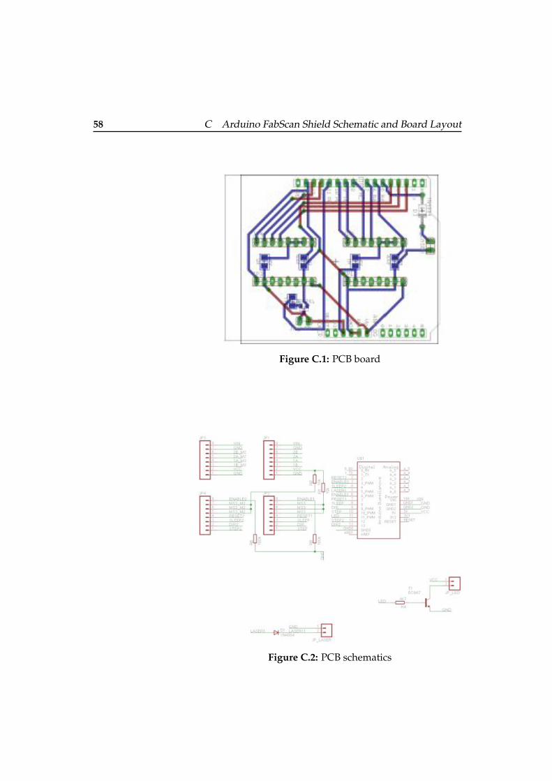
58 C Arduino FabScan Shield Schematic and Board Layout
Figure C.1: PCB board
Figure C.2: PCB schematics

59
Appendix D
Schematics for the 3DPrinter Parts
The files for the 3D printer parts are provided under thefollowing download link. The files are updated when thereis a new version available.
FabScan 3D Printer Parts a
ahttp://hci.rwth-aachen.de/tiki-download wiki attachment.php?attId=1389&download=y


61
Appendix E
Digital Content
The attached DVD-ROM contains the source code and theexecutables of ”FabScan” as well as the firmware for the Ar-duino. In addition, the DVD contains the point-clouds andsurface-meshes shown in the figures. All the files neededto built a hardware copy of the FabScan are also included.


63
Bibliography
[A94] LAURENTINI A. The Visual Hull Conceptfor Silhouette-Based Image Understanding.In IEEE TPAMI, pages 150–162, March 1994.
[AC01] N Amenda and S Choi. The power crust. Theproceeding of the ACM symposium on solid. . . , 2001.
[BK08] Gary Bradski and Adrian Kaehler. LearningOpenCV: Computer Vision with the OpenCV Li-brary. O’Reilly Media, 1st edition, October2008.
[BKM08] Aaron Bangor, Philip T Kortum, and James TMiller. An Empirical Evaluation of the Sys-tem Usability Scale. International Journalof Human-Computer Interaction, 24(6):574–594,July 2008.
[Bla04] F Blais. Review of 20 years range sensordevelopment. Journal of Electronic Imaging,September 2004.
[Bor01] Jan Borchers. A Pattern Approach to InteractionDesign. Wiley, 1 edition, May 2001.
[BP98] J.-Y. BOUGUET and P. PERONA. 3d photog-raphy on your desk, September 1998.
[Bro11] John Brooke. SUS - A quick and dirty usabil-ity scale. Technical report, September 2011.
[Car92] JM Carroll. Getting around the task-artifactcycle. ACM Transactions on Information Sys-tems . . . , 1992.

64 Bibliography
[CR08] M Corsini and G Ranzuglia. Meshlab:an open-source 3d mesh processing system.ERCIM News, 2008.
[FF11] STL File Format. http://mech.fsv.cvut.cz/dr/papers/ Lisbon04/node2.html, October2011.
[For05] USB Implementers Forum. Universal SerialBus Device Class Definition for Video De-vices, June 2005.
[Ger05] Neil Gershenfeld. FAB: The Coming Revolutionon Your Desktop–From Personal Computers toPersonal Fabrication. Basic Books, April 2005.
[GSGC08] Diego Gutierrez, Veronica Sundstedt, FerminGomez, and Alan Chalmers. Modeling lightscattering for virtual heritage. Journal on Com-puting and Cultural Heritage (JOCCH, 1(2), Oc-tober 2008.
[HMK82] E.L. Hall, C.A. MCPherson, and Tio J B K.Measuring curved surfaces for robot vision.Computer, 15(12):42–54, September 1982.
[HS97] J Heikkila and O Silven. A four-step cam-era calibration procedure with implicit imagecorrection. In Proceedings of the 1997 Confer-ence on Computer Vision and Pattern Recogni-tion, page 1106, February 1997.
[LIAI11] A Legarda, A Izaguirre, N Arana, and A Itur-rospe. A new method for Scheimpflug cam-era calibration. Electronics, Control, Measure-ment and Signals (ECMS), 2011 10th Interna-tional Workshop on, pages 1–5, 2011.
[LMW+11] T Leyvand, C Meekhof, Yi-Chen Wei, JianSun, and Baining Guo. Kinect Identity: Tech-nology and Experience. Computer, 44(4):94–96, 2011.
[LT09] Douglas Lanman and Gabriel Taubin. Buildyour own 3D scanner: 3D photography forbeginners. SIGGRAPH ’09: SIGGRAPH 2009Courses, August 2009.

Bibliography 65
[MLGG02] B Mikhak, C Lyon, T Gorton, and N Gershen-feld. Fab Lab: An alternate model of ICT fordevelopment. . . . on Development by . . . , 2002.
[NN94] K. S. NAYAR and Y NAKAGAWA. Shapefrom focus. In IEEE Trans. Pattern Anal. Mach.Intell. 16, pages 824–831, April 1994.
[Ope11] NI Open. Introducing OpenNIwww.openni.org, September 2011.
[PM83] F.J. Pipitone and T.G Marshall. A wide-fieldscanning triangulation rangefinder for ma-chine vision. International Journal of RoboticsResearch, 2(1):39–49, September 1983.
[RC11] Radu Bogdan Rusu and Steve Cousins. 3D ishere: Point Cloud Library (PCL). In Roboticsand Automation (ICRA), 2011 IEEE Interna-tional Conference on, pages 1–4, 2011.
[Rog11] Rick Rogers. Kinect with Linux. Linux Jour-nal, 2011(207), July 2011.
[SPSB04] J. SALVI, J PAGE S, and J. BATLLE. Patterncodification strategies in structured light sys-tems. In Pattern Recognition, pages 827–849,September 2004.
[SRDD06] S SEITZ, SZELISKI R, CURLESS B DIEBEL,and J SCHARSTEIN D. A comparison andevaluation of multi-view stereo recon- struc-tion algorithms. In CVPR 2006, June 2006.
[Uno11] Arduino Uno. http://arduino.cc/en/, Octo-ber 2011.
[WLZ10] Y. M Wang, Y Li, and J. B Zheng. A cam-era calibration technique based on OpenCV.In Information Sciences and Interaction Sciences(ICIS), 2010 3rd International Conference on,pages 403–406, 2010.
[WMMW06] Simon Winkelbach, Sven Molkenstruck, andFriedrich M Wahl. Low-Cost Laser RangeScanner and Fasst Surface Registration Ap-proach. DAGM, pages 1–11, September 2006.

66 Bibliography
[WN98] M. WATANABE and S. K. NAYAR. Rationalfilters for passive depth from defocus. In Int.J. Comput. Vision 27, pages 203–225, Septem-ber 1998.
[XRL11] Yuan Xin, Zhu Ruishuang, and Su Li. A Cali-bration Method Based on OpenCV. IntelligentSystems and Applications (ISA), 2011 3rd Inter-national Workshop on, pages 1–4, 2011.
[Zha00] Z Zhang. A flexible new technique for cam-era calibration. Pattern Analysis and MachineIntelligence, IEEE Transactions on, 22(11):1330–1334, 2000.

67
Index
Active Scanning . . . . . . . . . . . . . . . . . . . . . . . . . . . . . . . . . . . . . . . . . . . . . . . 7
Camera ray . . . . . . . . . . . . . . . . . . . . . . . . . . . . . . . . . . . . . . . . . . . . . . . . . . 14Contact based scanners . . . . . . . . . . . . . . . . . . . . . . . . . . . . . . . . . . . . . . . .5Correspondence problem . . . . . . . . . . . . . . . . . . . . . . . . . . . . . . . . . . . . . 6
Evaluation. . . . . . . . . . . . . . . . . . . . . . . . . . . . . . . . . . . . . . . . . . . . . . . .41–47Extrinsics . . . . . . . . . . . . . . . . . . . . . . . . . . . . . . . . . . . . . . . . . . . . . . . . . . . . 13
Future work . . . . . . . . . . . . . . . . . . . . . . . . . . . . . . . . . . . . . . . . . . . . . . 49–50
Intrinsics . . . . . . . . . . . . . . . . . . . . . . . . . . . . . . . . . . . . . . . . . . . . . . . . . . . . . 12
Laser range scanners . . . . . . . . . . . . . . . . . . . . . . . . . . . . . . . . . . . . . . . . . . 7
Non-contact based scanning . . . . . . . . . . . . . . . . . . . . . . . . . . . . . . . . . . . 6
Own work . . . . . . . . . . . . . . . . . . . . . . . . . . . . . . . . . . . . . . . . . . . . . . . . 17–39
Passive scanning . . . . . . . . . . . . . . . . . . . . . . . . . . . . . . . . . . . . . . . . . . . . . . 6Powercrust . . . . . . . . . . . . . . . . . . . . . . . . . . . . . . . . . . . . . . . . . . . . . . . . . . 14
Related work . . . . . . . . . . . . . . . . . . . . . . . . . . . . . . . . . . . . . . . . . . . . . . 5–15
Shape-from-silhouette . . . . . . . . . . . . . . . . . . . . . . . . . . . . . . . . . . . . . . . . . 6Stereoscopic imaging . . . . . . . . . . . . . . . . . . . . . . . . . . . . . . . . . . . . . . . . . . 6Structured light . . . . . . . . . . . . . . . . . . . . . . . . . . . . . . . . . . . . . . . . . . . . . . . 7Summary . . . . . . . . . . . . . . . . . . . . . . . . . . . . . . . . . . . . . . . . . . . . . . . . . . . . 49
Time-of-flight rangefinders . . . . . . . . . . . . . . . . . . . . . . . . . . . . . . . . . . . . 7

Typeset October 5, 2011