Fabrication of Thermo Electric Module for Cooling and ... · thermoelectric modules cover a wide...
5
International Journal of Science and Research (IJSR) ISSN (Online): 2319-7064 Index Copernicus Value (2013): 6.14 | Impact Factor (2013): 4.438 Volume 4 Issue 7, July 2015 www.ijsr.net Licensed Under Creative Commons Attribution CC BY Fabrication of Thermo Electric Module for Cooling and Heating Applications Using Solar Energy P. Amaanath 1 , K. Kalyani Radha 2 1 M.Tech student, Dept of Mechanical Engineering JNTUACEA Ananthapur, India 2 Assistant Professor of Mechanical Engineering JNTUA College of Engineering, Ananthapur, India Abstract: Thermo-Electric refrigeration is one of the recent developments in the field of refrigeration. The development of semiconductor technology enhanced the feasibility of Thermo-Electric applications to greater extent. Thermo-Electric refrigeration systems were worked based on the principle of Peltier effect, where the passage of direct electric current through the junction of two dissimilar semiconductor materials causes the junction to either cool down (absorbing heat) or warm up (rejecting heat) depending on direction of current. In the process of Thermo-Electric refrigeration the cooling effect was effectively utilized but heat energy developed by module is dissipated to environment. Now a day’s energy conservation plays a major role in day to day life due to energy crisis. Hence a solution has to be given to utilize the heat energy dissipated to environment for the useful heating applications and conserve waste heat energy. A novel idea of this is to utilize both heating and cooling effects generated by Thermo-Electric module. Cooling effect can be used for storage purpose and the waste heat energy for heat storage and used as hot pack. The power is given by both house hold supply and by solar energy for Thermo-Electric system for heating and cooling applications. Keywords: Thermo-Electric Refrigeration, Peltier effect, solar energy, cold storage, Thermo-Electric module. 1. Introduction The term refrigeration refers to cooling an area or substance below the environmental temperature, the process of removing heat. There are number of methods by which the refrigeration can be achieved. They are broadly classified into two categories: Non-Cyclic and Cyclic methods of Refrigeration. Non-cyclic refrigeration process consists of ice refrigeration and dry ice refrigeration. Cyclic process of refrigeration consists of vapour compression cycle, vapour absorption cycle, gas refrigeration cycle, thermo electric refrigeration etc... 1.1 Thermo-Electric refrigeration TER (Thermo Electric Refrigeration) modules were made up of two dissimilar metals that can be formed a junction in the 18 th century. The developed TEC modules were comes into existence after the invention of semiconductor technology. The concept of See beck effect enhances the thermo electricity which was discovered by Thomas See beck, a German scientist in 1821. The See beck effect states that “when two different conducting materials form a junction together and if we maintain a temperature difference across the junction, then an electric current flow in a closed circuit formed by two materials through the junction”. Another scientist named Jean Peltier found an opposite reaction to See beck effect, that was Peltier effect in 1834, which states that “the temperature difference occurs across the junction formed by two dissimilar conducting materials, when a Direct electric Current flows through the junction”. The module also called as peltier module and it produces heat on one side and cooling effect on other side when a Direct electric Current flows through it. This peltier effect can be used for refrigeration purpose. Applications for thermoelectric modules cover a wide spectrum of product areas. These include equipment used by military, medical, industrial, consumer, scientific/laboratory, and telecommunications organizations. 2. Operating Principle The operating principle of the TE modules is the peltier effect which states that “If the DC electric current flows through the junction of two dissimilar semiconductors, there is a temperature difference occurs across the junction”. The TE module produces cooling effect on one side and heating effect on other side when a DC current flows through the TE module. If the current direction changes, then the heating and cooling effects are also reversed means that the cooling effect occurs in place of heating effect and heating effect occurs in case of cooling effect. The TE module produces heating and cooling effects based on the current direction. The cooling effect and heating effects are also depends on the magnitude of DC current flows through the TE module. Formation of heat transfer occurs in the direction of current flow. By applying the current to the junction, then it transports heat from hot junction to cold junction. The peltier effect is opposite to see beck effect in which, by applying temperature difference across the junction of two dissimilar semiconductor materials produces electric current. Figure 1: Operating principle of TE module When DC power is applied to the TEC module, heat is moved from the cold surface to the hot surface. The direction in which the heat is pumped is directly related to the Paper ID: SUB157072 2442
Transcript of Fabrication of Thermo Electric Module for Cooling and ... · thermoelectric modules cover a wide...

International Journal of Science and Research (IJSR) ISSN (Online): 2319-7064
Index Copernicus Value (2013): 6.14 | Impact Factor (2013): 4.438
Volume 4 Issue 7, July 2015
www.ijsr.net Licensed Under Creative Commons Attribution CC BY
Fabrication of Thermo Electric Module for Cooling
and Heating Applications Using Solar Energy
P. Amaanath1, K. Kalyani Radha
2
1M.Tech student, Dept of Mechanical Engineering JNTUACEA Ananthapur, India 2Assistant Professor of Mechanical Engineering JNTUA
College of Engineering, Ananthapur, India
Abstract: Thermo-Electric refrigeration is one of the recent developments in the field of refrigeration. The development of
semiconductor technology enhanced the feasibility of Thermo-Electric applications to greater extent. Thermo-Electric refrigeration
systems were worked based on the principle of Peltier effect, where the passage of direct electric current through the junction of two
dissimilar semiconductor materials causes the junction to either cool down (absorbing heat) or warm up (rejecting heat) depending on
direction of current. In the process of Thermo-Electric refrigeration the cooling effect was effectively utilized but heat energy developed
by module is dissipated to environment. Now a day’s energy conservation plays a major role in day to day life due to energy crisis. Hence
a solution has to be given to utilize the heat energy dissipated to environment for the useful heating applications and conserve waste heat
energy. A novel idea of this is to utilize both heating and cooling effects generated by Thermo-Electric module. Cooling effect can be
used for storage purpose and the waste heat energy for heat storage and used as hot pack. The power is given by both house hold supply
and by solar energy for Thermo-Electric system for heating and cooling applications.
Keywords: Thermo-Electric Refrigeration, Peltier effect, solar energy, cold storage, Thermo-Electric module.
1. Introduction
The term refrigeration refers to cooling an area or substance
below the environmental temperature, the process of
removing heat. There are number of methods by which the
refrigeration can be achieved. They are broadly classified
into two categories: Non-Cyclic and Cyclic methods of
Refrigeration. Non-cyclic refrigeration process consists of
ice refrigeration and dry ice refrigeration. Cyclic process of
refrigeration consists of vapour compression cycle, vapour
absorption cycle, gas refrigeration cycle, thermo electric
refrigeration etc...
1.1 Thermo-Electric refrigeration
TER (Thermo Electric Refrigeration) modules were made up
of two dissimilar metals that can be formed a junction in the
18th
century. The developed TEC modules were comes into
existence after the invention of semiconductor technology.
The concept of See beck effect enhances the thermo
electricity which was discovered by Thomas See beck, a
German scientist in 1821. The See beck effect states that
“when two different conducting materials form a junction
together and if we maintain a temperature difference across
the junction, then an electric current flow in a closed circuit
formed by two materials through the junction”. Another
scientist named Jean Peltier found an opposite reaction to
See beck effect, that was Peltier effect in 1834, which states
that “the temperature difference occurs across the junction
formed by two dissimilar conducting materials, when a
Direct electric Current flows through the junction”. The
module also called as peltier module and it produces heat on
one side and cooling effect on other side when a Direct
electric Current flows through it. This peltier effect can be
used for refrigeration purpose. Applications for
thermoelectric modules cover a wide spectrum of product
areas. These include equipment used by military, medical,
industrial, consumer, scientific/laboratory, and
telecommunications organizations.
2. Operating Principle
The operating principle of the TE modules is the peltier
effect which states that “If the DC electric current flows
through the junction of two dissimilar semiconductors, there
is a temperature difference occurs across the junction”. The
TE module produces cooling effect on one side and heating
effect on other side when a DC current flows through the TE
module. If the current direction changes, then the heating and
cooling effects are also reversed means that the cooling
effect occurs in place of heating effect and heating effect
occurs in case of cooling effect. The TE module produces
heating and cooling effects based on the current direction.
The cooling effect and heating effects are also depends on
the magnitude of DC current flows through the TE module.
Formation of heat transfer occurs in the direction of current
flow. By applying the current to the junction, then it
transports heat from hot junction to cold junction. The peltier
effect is opposite to see beck effect in which, by applying
temperature difference across the junction of two dissimilar
semiconductor materials produces electric current.
Figure 1: Operating principle of TE module
When DC power is applied to the TEC module, heat is
moved from the cold surface to the hot surface. The direction
in which the heat is pumped is directly related to the
Paper ID: SUB157072 2442
International Journal of Science and Research (IJSR) ISSN (Online): 2319-7064
Index Copernicus Value (2013): 6.14 | Impact Factor (2013): 4.438
Volume 4 Issue 7, July 2015
www.ijsr.net Licensed Under Creative Commons Attribution CC BY
direction of the current. When the direction of the current is
reversed, the direction in which the heat is pumped is also
reversed. This phenomenon is known as the Peltier Effect
and it is the inverse of the Seebeck Effect (Godfrey et al.,
1996).
Before 1950, the COP of TEC modules is only about 1%.
Semiconductor materials were discovered in 1950, which
lead to the improvement in the COP. The semiconductors
have a much lower thermal conductivity than metals so that
the COP is improved up to 20% (Flurial et al., 1997).
On the hot surface of the TEC module, a large heat sink is
used to dissipate the heat that the TEC module has to pump
and the internal heat generated by the TEC module itself.
This heat is dissipated by the heat sink to the ambient air.
The temperature of the heat sink is therefore warmer than the
ambient temperature (Slack et al., 1998).
There is three ways of extracting the heat at the hot surface
of the TEC module. These include a heat sink with natural
convection (no fan), heat sink with forced convection (fan
included) and liquid cooling with forced convection. A heat
sink with natural convection has a temperature rise of 2°C/W
to 0.5°C/W. On the other hand, a heat sink with forced
convection has a temperature rise of 0.5°C/W to 0.02°C/W.
Liquid cooling has a temperature rise of 0.02°C/W to
0.005°C/W. In order to ensure reliability the hot surface
temperature of the TECM must be kept below 85°C (Riffat
and Xiaoli et al., 2003).
Thermo Electric refrigerator is designed and simulated to
maintain the temperature of enclosure at 4oC. The COP of
system will increase with increase of input current . COP is a
measure of module performance and it is always desirable to
increase or maximize. Selection of the proper thermo electric
module for a specific application requires an evaluation of
the total system in which the refrigeration will be used. The
selection of TEM material is based on nature of cooling
(Jyrki tervo et al., 2009 ).
Summary
In the process of thermo electric refrigeration the cooling
effect was effectively used for cooling applications such as
storage of medicines, vegetables etc... But heat energy
produced by TEC module dissipated to environment. Due to
energy crisis, it is important to conserve energy. The heat
energy dissipated to environment can be used for heating
applications such as hot packs. This technology enables the
TEC modules to use both heating and cooling applications at
a time and it leads to conservation of energy and recovery of
waste heat. In order to conserve conventional electricity, this
TER (Thermo-Electric Refrigeration) system is powered by
the solar panel arrangements.
3. Methodology
From the cooling load calculations, 105.83 W of load for
cooling space and 60.9 W of load for heating spaced
required. Depending upon the load, the modules are selected.
Figure 2: Proposed model design
Load calculations
Specifications of aluminium box
Length = 13cm
Width = 13cm
Height = 28cm
Volume = 13*13*28 = 4732cm3
Capacity = 4.732 lt
Cooling capacity required = m*c*dt
= 4.7*4.27*(33-14)
= 381KJ
= 105.83W
Module selection
Number of modules required = Cooling capacitu required
Cooling capacity of module
Cooling capacity of module = 45W
Number of modules required = 105.38
45 = 2.35
Hence 3 peltier modules are required to obtain the
temperature of 14oC inside the cold box. These 3 modules
can produce the temperature of 58oC on other side inside the
hot box.
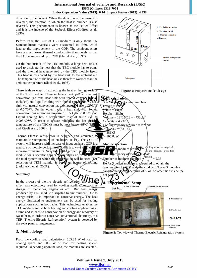
4. Experimental Setup
Figure 3: Top view of Thermo Electric Refrigeration system
Paper ID: SUB157072 2443

International Journal of Science and Research (IJSR) ISSN (Online): 2319-7064
Index Copernicus Value (2013): 6.14 | Impact Factor (2013): 4.438
Volume 4 Issue 7, July 2015
www.ijsr.net Licensed Under Creative Commons Attribution CC BY
Figure 4: Fabricated Thermo Electric Refrigerator system
powered by solar energy
1. Fabricated Thermo electric heating and cooling system. 2.
Solar panel. 3. Power supply from solar panel to battery
Figure 5: Block diagram
The experimental set up consisting of:
A. Thermo electric modules
B. Solar panel
C. Battery
D. Metal (aluminium boxes)
E. Heat sink with fan
F. Insulation
G. Power supply unit
The main parts of this project are explained below:
A. Thermo Electric modules
For the selected box capacity of 4.7 lit, three Thermo Electric
modules are used in the fabrication to obtain 14oC inside the
cold box and 58oC inside the hot box. The cooling capacity
of one module is 45W. The hot side surface of module is
mounting on heat sink. The modules are placed in between
the two boxes.
B. Solar panel Solar pane converts light energy into electrical energy. One
square meter of fixed array kept facing south yields nearly
0.5 KWh of electrical energy on a normal sunny day. Here
we use a 50 W solar panel with output of 16 V.
C. Battery Batteries are the devices which stores DC electrical energy in
form of chemical energy. In this systems batteries are used
for storage of excess solar energy converted into electrical
energy. In this fabrication we use a 12 V lead-acid battery.
D. Metal (aluminium boxes)
The aluminium box dimensions used in this project are
13*13*28 cm and the capacity of the box is 4.7 lit. Two
aluminium boxes are used, one for cold box and another for
hot box.
E. Heat sink with fan
Thermo Electric module hot side surface is mounted on the
heat sink to absorb the heat and the fan is used to transfer the
heat by forced convection in the hot box.
F. Insulation
A black foam insulation material is used to reduce the heat
losses to the surroundings around the two boxes. Cork board
insulation is placed in between two boxes to eliminate the
heat transfer from hot box to cold box through conduction.
G. Power supply unit
Power supply unit consisting of 230 V AC, 50 Hz house hold
supply, step-down transformer and rectifier circuit to charge
the battery when solar energy not available.
Assembly Procedure
First check whether TER module is working or not and
find out the cool side and hot side of module by sending
DC current through module.
Apply thermal conductive paste between module hot side
and heat sink. A 12 V DC fan connected to heat sink.
After mounting of module on heat sink, place in between
two aluminium boxes such that cold side of module
exposed to cold box and heat sink is exposed to hot box.
Black foam insulation is insulated outside surfaces of
boxes to eliminate heat losses to surroundings and cork
board insulation placed in between boxes to eliminate
heat transfer between boxes.
The battery is placed under the boxes and circuit
connections are given such that battery can supply
modules and DC fan. This arrangement is placed inside
the wooden box.
The battery can be charged either by solar panel or house
hold supply.
Experimentation
Experiments are conducted to analyse the COP and
efficiency. The power supply from the battery which is
charged by solar panel is given to system and readings of
temperatures at different places inside both boxes are taking
by placing the thermo couples near modules, at centre and
near corners for every 10 minutes of time. The readings are
tabulated and check for least temperatures occur in cold box
and maximum temperatures occur in hot box. After that the
power is switch OFF and checks for the storage times of the
two boxes and readings are taken. The tabulated values are
plotted as temperature vs time for power ON and OFF
conditions.
5. Results and Discussions
Paper ID: SUB157072 2444
International Journal of Science and Research (IJSR) ISSN (Online): 2319-7064
Index Copernicus Value (2013): 6.14 | Impact Factor (2013): 4.438
Volume 4 Issue 7, July 2015
www.ijsr.net Licensed Under Creative Commons Attribution CC BY
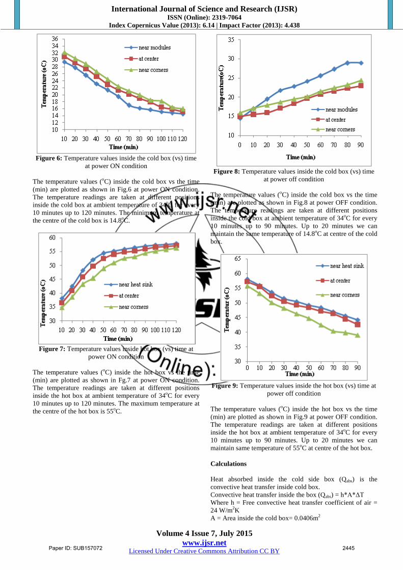
Figure 6: Temperature values inside the cold box (vs) time
at power ON condition
The temperature values (oC) inside the cold box vs the time
(min) are plotted as shown in Fig.6 at power ON condition.
The temperature readings are taken at different positions
inside the cold box at ambient temperature of 34oC for every
10 minutes up to 120 minutes. The minimum temperature at
the centre of the cold box is 14.8oC.
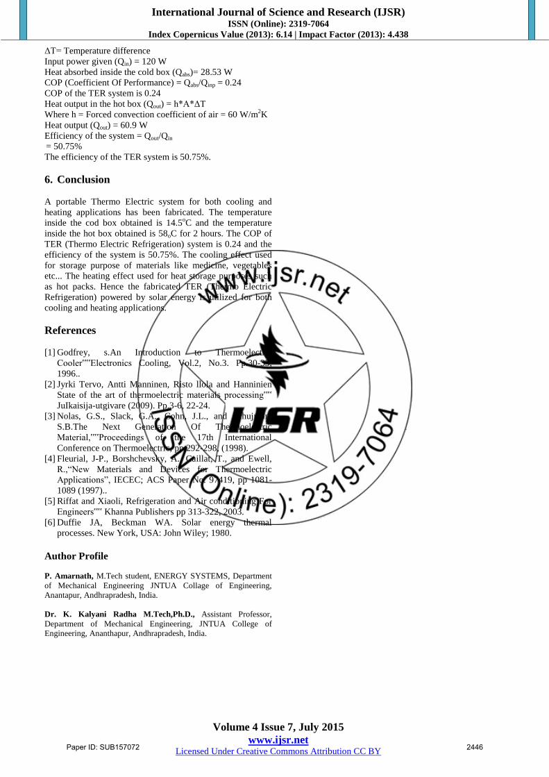
Figure 7: Temperature values inside hot box (vs) time at
power ON condition
The temperature values (oC) inside the hot box vs the time
(min) are plotted as shown in Fg.7 at power ON condition.
The temperature readings are taken at different positions
inside the hot box at ambient temperature of 34oC for every
10 minutes up to 120 minutes. The maximum temperature at
the centre of the hot box is 55oC.
Figure 8: Temperature values inside the cold box (vs) time
at power off condition
The temperature values (oC) inside the cold box vs the time
(min) are plotted as shown in Fig.8 at power OFF condition.
The temperature readings are taken at different positions
inside the cold box at ambient temperature of 34oC for every
10 minutes up to 90 minutes. Up to 20 minutes we can
maintain the same temperature of 14.8oC at centre of the cold
box.
Figure 9: Temperature values inside the hot box (vs) time at
power off condition
The temperature values (oC) inside the hot box vs the time
(min) are plotted as shown in Fig.9 at power OFF condition.
The temperature readings are taken at different positions
inside the hot box at ambient temperature of 34oC for every
10 minutes up to 90 minutes. Up to 20 minutes we can
maintain same temperature of 55oC at centre of the hot box.
Calculations
Heat absorbed inside the cold side box (Qabs) is the
convective heat transfer inside cold box.
Convective heat transfer inside the box (Qabs) = h*A*ΔT
Where h = Free convective heat transfer coefficient of air =
24 W/m2K
A = Area inside the cold box= 0.0406m2
Paper ID: SUB157072 2445
International Journal of Science and Research (IJSR) ISSN (Online): 2319-7064
Index Copernicus Value (2013): 6.14 | Impact Factor (2013): 4.438
Volume 4 Issue 7, July 2015
www.ijsr.net Licensed Under Creative Commons Attribution CC BY
ΔT= Temperature difference
Input power given (Qin) = 120 W
Heat absorbed inside the cold box (Qabs)= 28.53 W
COP (Coefficient Of Performance) = Qabs/Qinp = 0.24
COP of the TER system is 0.24
Heat output in the hot box (Qout) = h*A*ΔT
Where h = Forced convection coefficient of air = 60 W/m2K
Heat output (Qout) = 60.9 W
Efficiency of the system = Qout/Qin
= 50.75%
The efficiency of the TER system is 50.75%.
6. Conclusion
A portable Thermo Electric system for both cooling and
heating applications has been fabricated. The temperature
inside the cod box obtained is 14.5oC and the temperature
inside the hot box obtained is 58oC for 2 hours. The COP of
TER (Thermo Electric Refrigeration) system is 0.24 and the
efficiency of the system is 50.75%. The cooling effect used
for storage purpose of materials like medicine, vegetables
etc... The heating effect used for heat storage purposes such
as hot packs. Hence the fabricated TER (Thermo Electric
Refrigeration) powered by solar energy is utilized for both
cooling and heating applications.
References
[1] Godfrey, s.An Introduction to Thermoelectric
Cooler‟‟Electronics Cooling, Vol.2, No.3. Pp.30-33,
1996..
[2] Jyrki Tervo, Antti Manninen, Risto llola and Hanninien
State of the art of thermoelectric materials processing‟‟
JuIkaisija-utgivare (2009). Pp.3-6, 22-24.
[3] Nolas, G.S., Slack, G.A., Cohn, J.L., and Schujman,
S.B.The Next Generation Of Thermoelectric
Material,‟‟Proceedings of the 17th International
Conference on Thermoelectric, pp 292-298, (1998).
[4] Fleurial, J-P., Borshchevsky, A., Caillat, T., and Ewell,
R.,“New Materials and Devices for Thermoelectric
Applications”, IECEC; ACS Paper No. 97419, pp 1081-
1089 (1997)..
[5] Riffat and Xiaoli, Refrigeration and Air conditioning For
Engineers‟‟ Khanna Publishers pp 313-322, 2003.
[6] Duffie JA, Beckman WA. Solar energy thermal
processes. New York, USA: John Wiley; 1980.
Author Profile
P. Amarnath, M.Tech student, ENERGY SYSTEMS, Department
of Mechanical Engineering JNTUA Collage of Engineering,
Anantapur, Andhrapradesh, India.
Dr. K. Kalyani Radha M.Tech,Ph.D., Assistant Professor,
Department of Mechanical Engineering, JNTUA College of
Engineering, Ananthapur, Andhrapradesh, India.
Paper ID: SUB157072 2446