Fabrication and Testing of 2-Dimensional Z … · Fabrication and Testing of 2-Dimensional...
15
2D Z-EXPANDABLE AUXETIC TEXTILES FOR IMPACT PROTECTION 1 Fabrication and Testing of 2-Dimensional Z-Expandable Auxetic Textile Structures for Impact Protective Clothing Applications ASTM Student Project Grant 2013-2014 Harini Ramaswamy University of Minnesota-Twin Cities Advisor: Lucy Dunne 12/31/2014
Transcript of Fabrication and Testing of 2-Dimensional Z … · Fabrication and Testing of 2-Dimensional...

2D Z-EXPANDABLE AUXETIC TEXTILES FOR IMPACT PROTECTION 1
Fabrication and Testing of 2-Dimensional Z-Expandable Auxetic Textile
Structures for Impact Protective Clothing Applications
ASTM Student Project Grant 2013-2014
Harini Ramaswamy
University of Minnesota-Twin Cities
Advisor: Lucy Dunne
12/31/2014

2D Z-EXPANDABLE AUXETIC TEXTILES FOR IMPACT PROTECTION 2
ABSTRACT
Auxetic textiles become thicker when subjected to a stretch and are incorporated in
functional clothing design (Alderson, 2005). These counter-intuitive smart materials grow in
dimensions, in a direction that is perpendicular to the applied force. Among several applications
in technical textiles, auxetic materials are incorporated in elbow pads, knee pads and body armor
for impact protection and shock absorption. Unlike conventional substances that compress at the
point of impact and become vulnerable to breakage when subjected to a tensile stress, auxetic
planar materials push towards the point of impact, thereby making the material more resistant to
breakage. Since the ratio of the transverse to longitudinal strains (Poisson’s ratio) for these
materials are negative, these are also referred to as Negative Poisson’s Ratio (NPR) materials.
Most existing auxetic structures are two-dimensional and grow in the Y axis when stretched
along the X axis or vice-versa. Limited research has been directed towards the creation and testing
of three-dimensional auxetics that grow in the Z-direction, when subjected to stresses along the X
or Y axis. Further, the manufacture of 2D and 3D auxetics is generally complex (Mslija, A., &.
Lantada, D. A.). The purpose of this study was to engineer Z-expandable auxetic structures that
can be manufactured easily from a sheet-like textile material, for incorporation in an application
such as a kneepad. An adaptation of the ASTM D5034-09 ‘Standard Test Method for Breaking
Strength and Elongation of Textile Fabrics’ and ASTM D1777-64 ‘Standard Test Method for
Thickness of Textile Material’ was used to determine the engineering Poisson’s ratio-- a negative
value of which confirms auxeticity. The stresses that come into play during growth and recovery
were identified.
2D Z-EXPANDABLE AUXETIC TEXTILES FOR IMPACT PROTECTION 3
INTRODUCTION
Classification
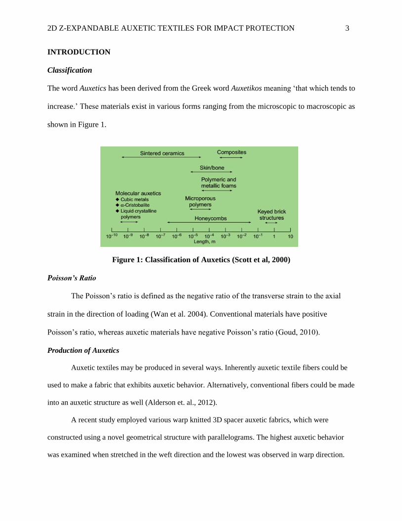
The word Auxetics has been derived from the Greek word Auxetikos meaning ‘that which tends to
increase.’ These materials exist in various forms ranging from the microscopic to macroscopic as
shown in Figure 1.
Figure 1: Classification of Auxetics (Scott et al, 2000)
Poisson’s Ratio
The Poisson’s ratio is defined as the negative ratio of the transverse strain to the axial
strain in the direction of loading (Wan et al. 2004). Conventional materials have positive
Poisson’s ratio, whereas auxetic materials have negative Poisson’s ratio (Goud, 2010).
Production of Auxetics
Auxetic textiles may be produced in several ways. Inherently auxetic textile fibers could be
used to make a fabric that exhibits auxetic behavior. Alternatively, conventional fibers could be made
into an auxetic structure as well (Alderson et. al., 2012).
A recent study employed various warp knitted 3D spacer auxetic fabrics, which were
constructed using a novel geometrical structure with parallelograms. The highest auxetic behavior
was examined when stretched in the weft direction and the lowest was observed in warp direction.

2D Z-EXPANDABLE AUXETIC TEXTILES FOR IMPACT PROTECTION 4
The auxetic behavior also reduced with increase in tensile strain. It was also revealed that the auxetic
fabric will retain 65% of its effect after 10 cycles of extension. These novel auxetic geometric
configurations make it attractive for potential applications like sports and protection (Wang et al.,
2013). In another recent research study, ‘rotating square’ auxetic structures (Figure 2) with enhanced
mechanical properties were designed and manufactured for the application of stents for palliative
treatment of esophageal cancer. Polyurethane foam sheets were laser cut to the desired structures
using the CNC guided laser cutter and the compressive stress-strain behavior was tested on the
Instron. Employing the auxetic cell geometry improved the stenting outcomes. The material could get
wider when stretched, offer stiffness without being brittle and minimize stresses (Bhullar S.K., et al.,
2013).
Figure 2: Rotating Square Auxetics with holes (left) and without holes (right) (Bhullar S.K., et
al., 2013, p 44)
Properties
Auxetic materials are suitable for fitting the human body. The ability of the structure to open
out when stretched leads to enhanced air permeability under tension. (Wang, et. al., 2013).
Auxetic materials exhibit synclastic behavior in that they curve in the same direction of the bending
force (Lakes, 1987; Evans, 1990; Cherfas, 1990). In the case of wearable auxetics, this means that the
structure would offer more conformability while offering impact protection.
2D Z-EXPANDABLE AUXETIC TEXTILES FOR IMPACT PROTECTION 5
Applications
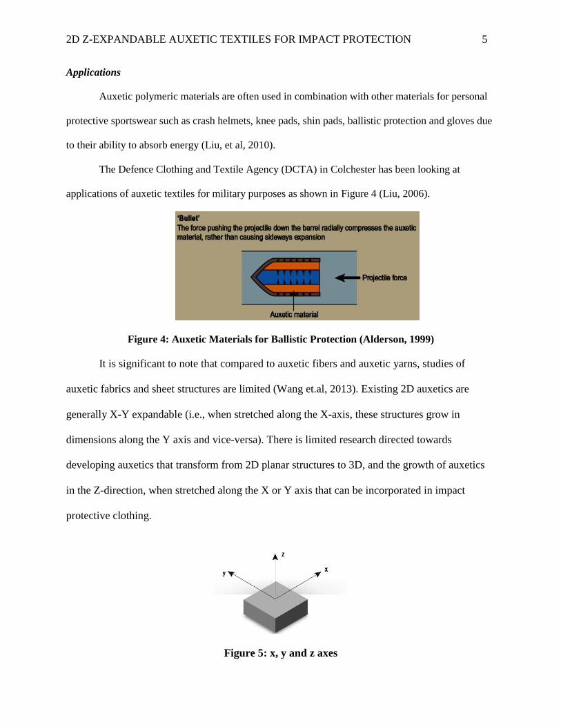
Auxetic polymeric materials are often used in combination with other materials for personal
protective sportswear such as crash helmets, knee pads, shin pads, ballistic protection and gloves due
to their ability to absorb energy (Liu, et al, 2010).
The Defence Clothing and Textile Agency (DCTA) in Colchester has been looking at
applications of auxetic textiles for military purposes as shown in Figure 4 (Liu, 2006).
Figure 4: Auxetic Materials for Ballistic Protection (Alderson, 1999)
It is significant to note that compared to auxetic fibers and auxetic yarns, studies of
auxetic fabrics and sheet structures are limited (Wang et.al, 2013). Existing 2D auxetics are
generally X-Y expandable (i.e., when stretched along the X-axis, these structures grow in
dimensions along the Y axis and vice-versa). There is limited research directed towards
developing auxetics that transform from 2D planar structures to 3D, and the growth of auxetics
in the Z-direction, when stretched along the X or Y axis that can be incorporated in impact
protective clothing.
Figure 5: x, y and z axes

2D Z-EXPANDABLE AUXETIC TEXTILES FOR IMPACT PROTECTION 6
METHODOLOGY
Figure 6 highlights the scope for innovation in auxetics related to this project.
Figure 6: Mind map showing scope for innovation in Auxetics
The objectives of this project were to create auxetic textile structures that:
(i) Demonstrate growth in the Z direction (normal to the plane), when stretched
along the X or Y axis, thereby transforming from 2D to 3D in the process.
(ii) Are elastic in nature (i.e., auxetics return to their original configuration once the
stresses that they are subjected to are removed). In other words, the deformation
that these structures undergo would not be permanent and the growth along Z-
direction is retained only as long as the structure is subjected to a stress along the
X or Y direction.
(iii) Can be easily fabricated from a sheet-type textile material such foam and (or)
fabric.

2D Z-EXPANDABLE AUXETIC TEXTILES FOR IMPACT PROTECTION 7
Ideation
Various material and design directions were explored as part of open and structured
ideation. Explanation for the creation of these structures is beyond the scope of this report.
Herringbone Structures Wave and Arc Structures Swastika (卐) inspired structures
(i)Paper prototypes with slits
(ii)Open-celled foam prototypes
(iii)Closed-celled foam prototypes (iv) Origami prototypes
(iv)Fabric and industrial felt/foam integrated prototypes
Figure 7: Thumbnails of some materials and methods used
2D Z-EXPANDABLE AUXETIC TEXTILES FOR IMPACT PROTECTION 8
Manufacturing
Rotating Triangles
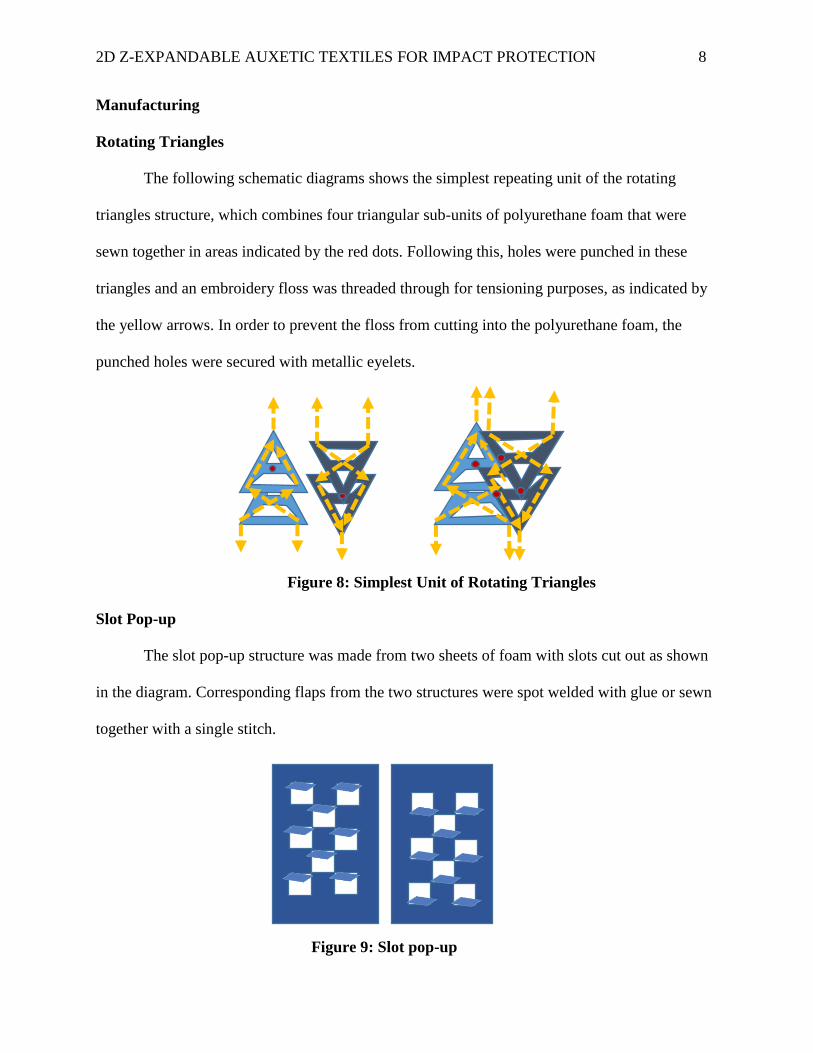
The following schematic diagrams shows the simplest repeating unit of the rotating
triangles structure, which combines four triangular sub-units of polyurethane foam that were
sewn together in areas indicated by the red dots. Following this, holes were punched in these
triangles and an embroidery floss was threaded through for tensioning purposes, as indicated by
the yellow arrows. In order to prevent the floss from cutting into the polyurethane foam, the
punched holes were secured with metallic eyelets.
Figure 8: Simplest Unit of Rotating Triangles
Slot Pop-up
The slot pop-up structure was made from two sheets of foam with slots cut out as shown
in the diagram. Corresponding flaps from the two structures were spot welded with glue or sewn
together with a single stitch.
Figure 9: Slot pop-up

2D Z-EXPANDABLE AUXETIC TEXTILES FOR IMPACT PROTECTION 9
Testing
Rotating triangles and slot pop-up that were refined and considered for final testing are
presented in this study. Images and videos were captured. The images below show front and side
views of the prototypes, when subjected to a stretch test on the Instron.
Figures 8 (i)-(vi)Rotating Triangles (labelled from left to right)
(i)(ii)Relaxed Views (iii)(iv)Intermediate Stretch Positions (v)(vi)Completely stretched
Figures 9 (i)-(iv) Slot Pop-up (labelled from left to right)
(i)(ii) Relaxed View (iii)(iv) Completely stretched
The ASTM D5034-09 ‘Standard Test Method for Breaking Strength and Elongation of
Textile Fabrics and ASTM D1777-64 ‘Standard Test Method for Thickness of Textile Material’
were adapted for the purpose of this study. The structures considered were made to 9.25 inches
(length) x 5 inches (width) and 0.125 inches (thickness), from closed-cell polyurethane sheets.

2D Z-EXPANDABLE AUXETIC TEXTILES FOR IMPACT PROTECTION 10
Tensile Testing Machine
The testing was performed on the Instron 5544 Constant Rate of Elongation (CRE) type
machine in which the specimen is subjected to elongation of 0.50 inches at a uniform rate.
Measurement
The amount of stretch or elongation that the specimen undergoes during tensile testing is
expressed in the form of strain. For the purposes of this study, engineering strain (the ratio of the
change in length to the original length) of the specimen was determined for the Y and Z axes.
Using these values, the engineering Poisson’s ratio (ratio of the transverse strain to the
longitudinal strain) was determined.
Clamping or Holding Devices
Specimens were mounted on the clamps manually. Clamp liners were used in order to
preclude slippage and minimize specimen failure in the clamped areas.
Calibrating Devices
The machine had a steel rule running along the longitudinal direction to measure length.
A ruler was also attached along the transverse direction in order to measure the change in
thickness. In the case of the rotating triangles structure, thickness was determined by measuring
the distance between a pair of cardboard sheets without parallax error. Length and thickness
measurements were recorded. Images and videos of the mounted structures in various positions
were also captured.
Figure 10: Measuring Thickness of Samples
2D Z-EXPANDABLE AUXETIC TEXTILES FOR IMPACT PROTECTION 11
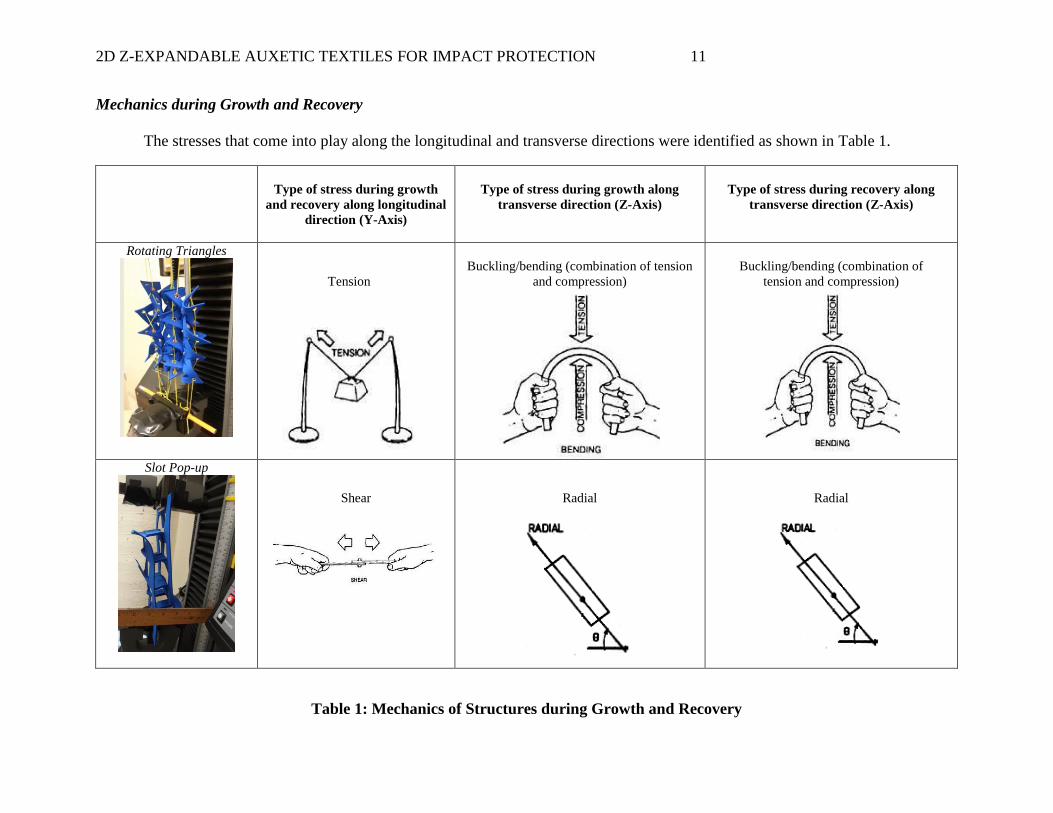
Mechanics during Growth and Recovery
The stresses that come into play along the longitudinal and transverse directions were identified as shown in Table 1.
Type of stress during growth
and recovery along longitudinal
direction (Y-Axis)
Type of stress during growth along
transverse direction (Z-Axis)
Type of stress during recovery along
transverse direction (Z-Axis)
Rotating Triangles
Tension
Buckling/bending (combination of tension
and compression)
Buckling/bending (combination of
tension and compression)
Slot Pop-up
Shear
Radial
Radial
Table 1: Mechanics of Structures during Growth and Recovery

2D Z-EXPANDABLE AUXETIC TEXTILES FOR IMPACT PROTECTION 12
RESULTS AND DISCUSSION
For various lengths of stretch, corresponding thicknesses were recorded, until two
consecutive thickness values were obtained, as shown in Table 2 indicating saturation. At 12.5
inches, in the case of the rotating triangles structure, the structure did not expand beyond 2
inches and in the case of the slot pop-up, the slots started reversing beyond an extension of 10.5
inches and reached 0.25 inches.
No. Length (Inches) Thickness (Inches)
Rotating Triangles Slot Pop-up
1 9.25 0.25 (when mounted in relaxed
position) and 0.125 (actual)
0.25 (when mounted in relaxed
position) and 0.125 (actual)
2 9.5 0.75 0.5
3 9.75 1 0.75
4 10 1.50 1
5 10.5 1.75 1.25
6 11 2 0.75
7 11.5 2 0.5
8 12 2 0.25
9 12.5 2 0.25
Table 2: Thickness obtained for Various Lengths
Graphs for Rotating Triangles and Slot Pop-up
0
0.5
1
1.5
2
2.5
9.25 10.25 11.25 12.25 13.25
Rotating Triangles: Length vs. Thickness
0
0.2
0.4
0.6
0.8
1
1.2
1.4
9.25 10.25 11.25 12.25 13.25
Slot Pop-up: Length vs. Thickness

2D Z-EXPANDABLE AUXETIC TEXTILES FOR IMPACT PROTECTION 13
Auxeticity of both the structures were determined from the Engineering Poisson’s ratio
values, based on the formula provided below.
Strain Transverse T2-T1
Engineering Poisson’s Ratio = - = - T1
Strain Longitudinal L2-L1
L1
It is to be noted that in the case of a conventional non-auxetic material, when the value of
Strain Longitudinal is positive, Strain Transverse is negative because a stretch along the longitudinal
direction will result in a compression along the transverse direction. The formula is usually
assigned a negative sign, so that the resultant Poisson’s ratio is positive. However, in the case of
auxetic materials, since a stretch along the longitudinal direction would result in expansion along
the transverse direction, the Strain Longitudinal and Strain Transverse will carry positive signs, and
therefore, the resultant Poisson’s ratio will be negative.
The samples were subjected to ten cycles of minimum and maximum (Table 3) stretch
and the average values of these were used to calculate the Poisson’s ratio.
Rotating Triangles Slot Pop-up
Length Thickness Length Thickness
Average Minimum Stretch(inches) 9.25 (L1) 0.125 (T1) 9.25 (L1) 0.125 (T1)
Average Maximum Stretch (inches) 11 (L2) 2 (T2) 10.5 (L2) 1.25 (T2)
Engineering Poisson’s Ratio -79 -67
Table 3: Minimum and Maximum Stretch Values
The structures considered for this study are anisotropic because they do not have
identical properties along every direction. Poisson’s ratio for isotropic materials that stretch
uniformly in all directions ranges between -1 to 0.5. Anisotropic materials can an arbitrary value
of any magnitude, as is the case for these two structures (Ting, T. C. T., & Chen, T., 2005).

2D Z-EXPANDABLE AUXETIC TEXTILES FOR IMPACT PROTECTION 14
CONCLUSIONS
Conventional auxetics grow along the Y axis when stretched along X axis and vice-versa.
The manufacture of auxetics is generally complex. This endeavor demonstrates successful
creation of easily manufacturable 2D Z-expandable auxetic structures that can be incorporated in
an impact protective application such as kneepad. These materials would grow thicker and retain
their expanded configuration along the Z axis (transverse direction) for as long as there is a
stretch along the Y axis (longitudinal direction). Various material and design directions were
explored during the course of open and structured idea generation phases. Rotating Triangles and
Slot Pop-up structures were fabricated from Polyurethane foam. The ASTM D5034-09 for
elongation and ASTM D1777-64 method for thickness were adapted and applied. The mechanics
during growth and recovery were also identified. The results reveal that the structures are
anisotropic (do not have identical properties along every direction) and are therefore
characterized by unusual Engineering Poisson’s ratio values.

2D Z-EXPANDABLE AUXETIC TEXTILES FOR IMPACT PROTECTION 15
REFERENCES
Alderson, A., A triumph of lateral thought, Chemistry & Industry, pp.384-391, 17 May 1999.
Alderson K, Alderson A,. (2005) Expanding materials and applications: exploiting auxetic textiles, Tech Textiles Int.
777, pp29-34.
Alderson, K., Alderson, A., Anand, S., Simkins, V., Nazare, S., & Ravirala, N. (2012). Auxetic warp knit textile
structures. physica status solidi (b), 249(7), pp 1322-1329.
Askew, G. N., Formenti, F., & Minetti, A. E. (2012). Limitations imposed by wearing armour on Medieval soldiers'
locomotor performance. Proceedings of the Royal Society B: Biological Sciences, 279(1729), 640-644.
Bhullar S.K., A. MawananeHewage T, Alderson A, Alderson K, Martin B. G. Jun. Influence of Negative Poisson's
Ratio on Stent Applications. Advances in Materials.Vol. 2, No. 3, 2013, pp. 42-47. doi:
10.11648/j.am.20130203.14.
Cherfas, J., Stretching the point, Science, p.247 & 630, 1990.
Evans, K.E., Tailoring the negative Poisson’s ratio, Chem. Ind., Vol.20, pp.654-657, 1990.
Goud, V. S. (2010). Auxetic textiles. Colourage, 57(6), pp 45-48.
Lakes, R.S. (1987a), Foam structures with a negative Poisson's ratio, Science, Vol. 235,
pp.1038-1040 1987. Lim, T. C., Alderson, A., & Alderson, K. L. (2013). Experimental studies on the impact
properties of auxetic materials. physica status solidi (b).
Liu, Y., & Hu, H. (2010). A review on auxetic structures and polymeric materials. Scientific Research and Essays,
5(10), 1052-1063.
Liu, Y., Hu, H., Long, H., & Zhao, L. (2012). Impact compressive behavior of warp-knitted spacer fabrics for
protective applications. Textile Research Journal,82(8), 773-788.
Liu, Q. (2006). Literature Review: Materials with Negative Poisson's Ratios and Potential Applications to
Aerospace and Defence (No. DSTO-GD-0472). Defence Science and Technology Organization Victoria
(Australia) Air Vehicles Division.
Maldovan, M., & Thomas, E. L. (2009). Periodic Materials and Interference Lithography: For Photonics,
Phononics and Mechanics. John Wiley & Sons, p 234.
Muslija, A., & Lantada, A. D. (2014). Deep reactive ion etching of auxetic structures: present capabilities and
challenges. Smart Materials and Structures, 23(8), 087001.
Stott, P.J., R. Mitchell, K. Alderson and A. Alderson, A growing industry, Materials World,
vol. 8, pp.12-14, 2000.
Smith, C.W., Evans, K.E. and Lehaman, F., Strain densification during indentation in
auxetic foams, Cell. Poly., Vol.18, pp.79-101, 1999.
Ting, T. C. T., & Chen, T. (2005). Poisson's ratio for anisotropic elastic materials can have no
bounds. The quarterly journal of mechanics and applied mathematics, 58(1), 73-82.
Wang, Z., & Hu, H. (2013). 3D auxetic warp‐knitted spacer fabrics. physica status solidi (b).