Fabric filter - jasakonsultanlingkungan.files.wordpress.com · Proses Filtrasi Fabric Filter...
94
Fabric filter Rachmat Boedisantoso Jurusan Teknik Lingkungan FTSP – ITS Kampus Sukolilo, Surabaya – 60111 TEKNOLOGI PENGENDALIAN PENCEMAR UDARA
Transcript of Fabric filter - jasakonsultanlingkungan.files.wordpress.com · Proses Filtrasi Fabric Filter...

Fabric filter
Rachmat Boedisantoso Jurusan Teknik Lingkungan FTSP – ITS
Kampus Sukolilo, Surabaya – 60111
TEKNOLOGI PENGENDALIAN
PENCEMAR UDARA
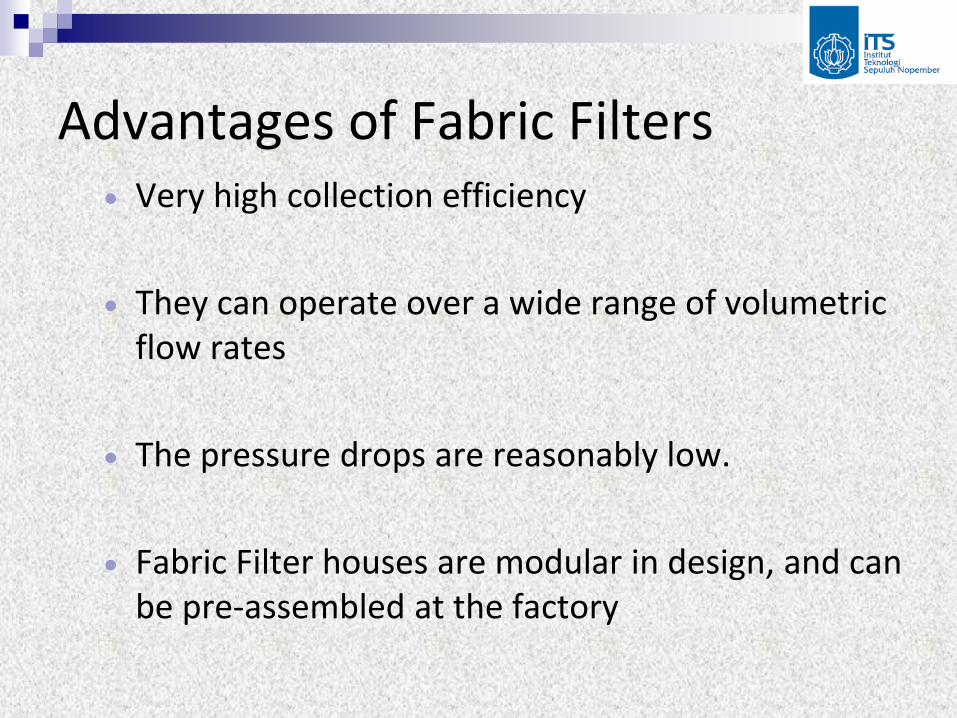
Advantages of Fabric Filters Very high collection efficiency
They can operate over a wide range of volumetric flow rates
The pressure drops are reasonably low.
Fabric Filter houses are modular in design, and can be pre-assembled at the factory

Fabric Filters (contd.) Disadvantages of Fabric Filters
Fabric Filters require a large floor area.
The fabric is damaged at high temperature.
Ordinary fabrics cannot handle corrosive gases.
Fabric Filters cannot handle moist gas streams
A fabric filtration unit is a potential fire hazard

Fabric Filters Principle
The filters retain particles larger than the mesh size
Air and most of the smaller particles flow through. Some of the smaller particles are retained due to interception and diffusion.
The retained particles cause a reduction in the mesh size.
The primary collection is on the layer of previously deposited particles.

Fabric Filtration merupakan alat kontrol
udara yang paling umum dipergunakan
Fabric filter menggunakan filter yang
terbuat dari nilon atau wol
Partikulat yang telah disisihkan/
terkumpul kemudian dibersihkan
dengan mekanisme pembersihan
tertentu.
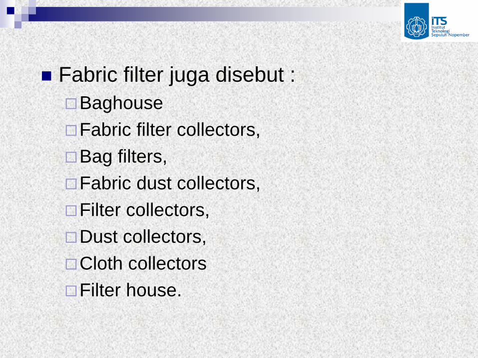
Fabric filter juga disebut :
Baghouse
Fabric filter collectors,
Bag filters,
Fabric dust collectors,
Filter collectors,
Dust collectors,
Cloth collectors
Filter house.

keuntungan dan kerugian Fabric Filter :
Keuntungan penggunaan fabric filter adalah : Efisiensi sangat tinggi, bahkan untuk partikel yang halus
Dapat dipakai untuk berbagai macam debu
Dapat untuk volume gas yang besar
Dapat beroperasi pada pressure drop yang rendah
Sedangkan kerugiannya adalah : Memerlukan tempat luas
Bahan filter dapat rusak pada temperatur tinggi atau bahan asam
Tidak dapat beroperasi pada lingkungan yang lembab
Potensial kebakaran

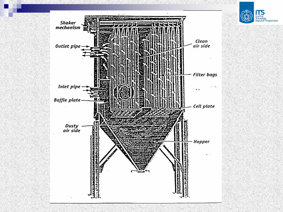
Fabric filter terdiri atas :
inlet,
outlet,
filter bag,
hopper

Mekanisme pengumpulan Fabric Filter pada
umumnya ada tiga cara utama, yaitu :
Impaction, partikel memiliki gaya inersia yang terlalu besar untuk mengikuti aliran garis pada filter fiber sehingga tertumbuk pada permukaan filter
Interception, partikel mempunyai inersia yang sangat kecil (partikel yg lebih kecil). Partikel akan berada pada aliran viscous, bergerak melambat dan menyentuh barrier dan berhenti
Diffusion, partikel lebih kecil dari 1 mikron berada pada kisaran gerak Brown, sehingga terjadi gerakan random yang akhirnya terintersepsi dengan dust cake

Proses Filtrasi Fabric Filter terdapat dua jenis
desain yang dapat digunakan yaitu:
Interior Filtration, partikulat dikumpulkan pada bagian dalam dari bag filter. Gas yang mengandung partikulat memasuki fabric filter melalui bagian bawah dari kolektor dan diarahkan ke dalam bag dengan menggunakan diffuser vanes atau baffle dan juga cell plate.
Exterior Filtration, partikulat dikumpulkan pada bagian luar dari bag fliter. Proses penyaringan berlangsung dari luar bag filter ke dalam bag filter.

Jenis Proses filtrasi ( kiri : Interior Filtrasi, kanan : Eksterior
Filtrasi)

Terdapat beberapa cara pembersihan yang dapat
dipergunakan untuk menyisihkan partikulat yang menempel
pada permukaan bag filter, tiga cara yang paling sering
digunakan adalah :
(i). Shaking
Mechanical shaking menggunakan motor yang dihubungkan dengan bag
Energi yang diperlukan rendah
Gerakan dan kecepatan tergantung endapan debu
Arah gerakan Horisontal atau vertical
Gerakan di bagian atas frame tempat bag diletakkan
Aliran gas berhenti saat dilakukan proses pembersihan

Shaker baghouse umumnya menggunakan interior filtration
Diameter 15,2 – 45,7 cm ( 6-18 inch )
Panjang sampai 12,2 m ( 40 ft )
Lama pembersihan 30 dt – beberapa menit
Terdiri dari beberapa kompartemen

(ii). Reverse Air
Mekanisme yang paling sederhana
Aliran udara kotor dihentikan
Mengalirkan backwash air (udara bersih yang berlawanan arah)
Aliran udara bertekanan rendah
Debu akan jatuh ke hopper
Lama pembersihan 30 menit – beberapa jam
Durasi pembersihan 10 – 30 detik
Terdapat ring dengan jarak 10 – 46 cm
Reverse air baghouse berdiameter 20 – 46 cm, dan panjang 6,1 – 12,2 cm
Terdiri dari beberapa kompartemen
Gambar 7.14 menunjukkan typical reverse air

Typical Reverse Air Baghouse

(iii). Pulse Jet
Disebut juga pressure jet cleaning
40 – 50% baghouse baru di Amerika
Menggunakan high pressure jet dari udara
Sistem exterior filtration
Menimbulkan shock wave
Pulse jet baghouse berdiameter 10,2 – 16,2 cm
Panjang umumnya 2,4 – 3,7, tapi dapat mencapai 7,6 cm
Bahan bag house
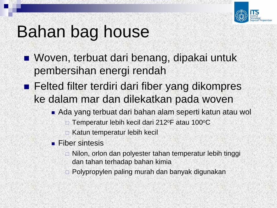
Woven, terbuat dari benang, dipakai untuk
pembersihan energi rendah
Felted filter terdiri dari fiber yang dikompres
ke dalam mar dan dilekatkan pada woven Ada yang terbuat dari bahan alam seperti katun atau wol
Temperatur lebih kecil dari 212oF atau 100oC
Katun temperatur lebih kecil
Fiber sintesis
Nilon, orlon dan polyester tahan temperatur lebih tinggi
dan tahan terhadap bahan kimia
Polypropylen paling murah dan banyak digunakan

Nilon memiliki abrasive resistant yang paling tinggi
Polyester atau Dacron baik untuk menahan asam, alkali dan abrasi dan relatif murah
Nomex buatan Dupont
Membran material terbuat dari berbagai jenis fiber yang disusun membentuk membrane diantaranya adalah Gore-Tex membrane, jenis ini dapat mereduksi emisi dengan baik, pressure drop yang relatif rendah, umur bag yang meningkat dan ratio air-cloth yang lebih tinggi

Design of Fabric Filters The equation for fabric filters is based on
Darcy’s law for flow through porous media.
Fabric filtration can be represented by the following equation: S = Ke + Ksw Where,
S = filter drag, N-min/m3
Ke = extrapolated clean filter drag, N-min/m3
Ks = slope constant. Varies with the dust, gas and fabric, N-min/kg-m
W= Areal dust density = LVt, where
L = dust loading (g/m3), V = velocity (m/s)
Both Ke and Ks are determined empirically from pilot tests.

Fabric Filters
Δ P Total pressure drop
Δ Pf Pressure drop due to the fabric
Δ Pp Pressure drop due to the particulate layer
Δ Ps Pressure drop due to the bag house structure
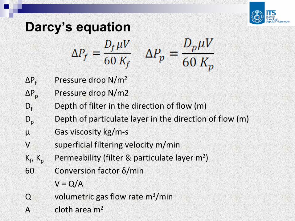
Darcy’s equation
ΔPf Pressure drop N/m2
ΔPp Pressure drop N/m2
Df Depth of filter in the direction of flow (m)
Dp Depth of particulate layer in the direction of flow (m)
μ Gas viscosity kg/m-s
V superficial filtering velocity m/min
Kf, Kp Permeability (filter & particulate layer m2)
60 Conversion factor δ/min
V = Q/A
Q volumetric gas flow rate m3/min
A cloth area m2

Dust Layer
L Dust loading kg/m3
t time of operation min ρL Bulk density of the particulate layer kg/m3
ΔP = ΔPf + ΔPp
Filter Drag S = ΔP/V Areal dust density W = LVt S= k1+k2W
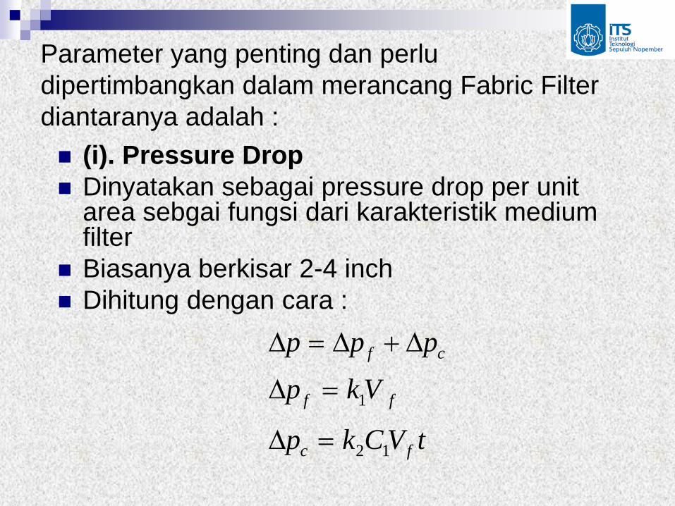
Parameter yang penting dan perlu
dipertimbangkan dalam merancang Fabric Filter
diantaranya adalah :
(i). Pressure Drop
Dinyatakan sebagai pressure drop per unit area sebgai fungsi dari karakteristik medium filter
Biasanya berkisar 2-4 inch
Dihitung dengan cara :
tVCkp
Vkp
ppp
fc
ff
cf
12
1

dimana : pf = pressure drop sepanjang FF
k1 = resistensi FF (inch air /menit atau cm/menit), merupakan fungsi dari karakteristik viscositas gas dan filter seperti ketebalan dan porositas (permeabilitas)
Vf = kecepatan filtrasi (ft/menit atau m/menit)
pf = pressure drop sepanjang cake dalam inch (cm)
k2 = resistensi dari cake (inch air /menit atau cm/menit
C1 = dust loading (lb/ft3 atau kg/m3) ditentukan secara experimen. Koefisien ini tergantung dari viscositas gas, densitas partikel dan porositas.
tVCkp
Vkp
ppp
fc
ff
cf
12
1

(ii). Kecepatan Penyaringan
Kecepatan penyaringan dinyatakan
sebagai :
kecepatan merupakan kecepatan
superficial filtering
A
Q

(iii). Performance Factor
Salah satu variable yang penting dalam mendesain baghouse adalah ratio air to cloth (A/C) atau ratio udara terhadap bahan filter
A/C menggambarkan berapa banyak gas kotor yang melewati permukaan filter dengan luas tertentu selama waktu tertentu.
Ratio yang tinggi berarti sejumlah besar udara yang melewati fabric
Satuan cm3/detik/cm2 atau ft3/menit/ft2
Tergantung dari mekanisme pembersihan, bahan filter dan partikel dust yang tersaring
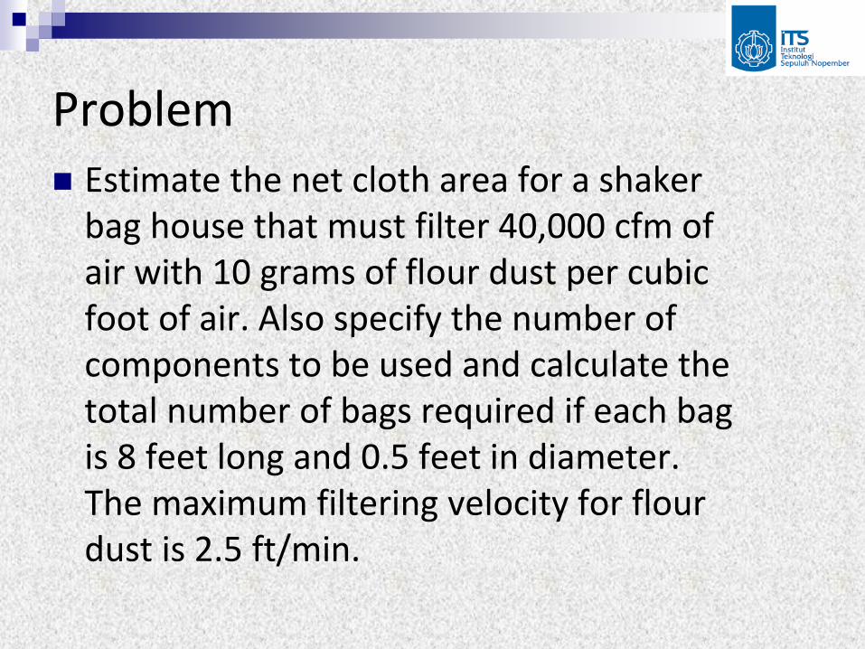
Problem Estimate the net cloth area for a shaker
bag house that must filter 40,000 cfm of air with 10 grams of flour dust per cubic foot of air. Also specify the number of components to be used and calculate the total number of bags required if each bag is 8 feet long and 0.5 feet in diameter. The maximum filtering velocity for flour dust is 2.5 ft/min.

Solution Step 1: Calculate total area and number of
components required: A = Q/V
Step 2:
Calculate the area of each bag: A = Π(d)l
Step 3:
Calculate the total number of bags required.
Number of bags required = Total area / Area per bag = 1270 bags

30
2. Dividing Collection Devices
Filters and scrubbers do not drive the
particles to a wall, but rather divide the
flow into smaller parts where they can
collect the particles.
2.1 Surface Filters
A surface filter is a membrane (sheet steel,
cloth, wire mesh, or filter paper) with holes
smaller than the dimensions of the
particles to be retained.

31
However, one only needs to ponder the
mechanical problem of drilling holes of
0.1-µ diameter or of weaving a fabric with
threads separated by 0.1µ to see that
such filters are not easy to produce.
They are much too expensive and fragile
for use as high-volume industrial air
cleaners.

32
Although industrial air filths rarely have holes smaller than the smallest particles captured, they often act as if they did.
The reason is that, as fine particles are caught on the sides of the holes of a filter, they tend to bridge over the holes and make them smaller.
Thus as the amount of collected particles increases, the cake of collected material becomes the filter.
33
The particles collect on the front surface of
the growing cake.
For that reason this is called a surface
filter.
The flow through a simple filter is shown
schematically in Fig. 9.12.


35
If we follow the gas stream in Fig. 9.12
from point 1 to point 3 we see that the flow
is horizontal and has a small change in
velocity because the pressure drop,
causing the gas to expand, and because
the gas is leaving behind its contained
particles.

36
In most industrial filters, both for gases and liquids,
the flow velocity in the individual pores is so low that
the flow is laminar.
Therefore, we may use the well-known relations for
laminar flow of a fluid in a porous medium, which
indicate
Here, k is the permeability, a property of the bed.
(19)s
Q p k
A x
37
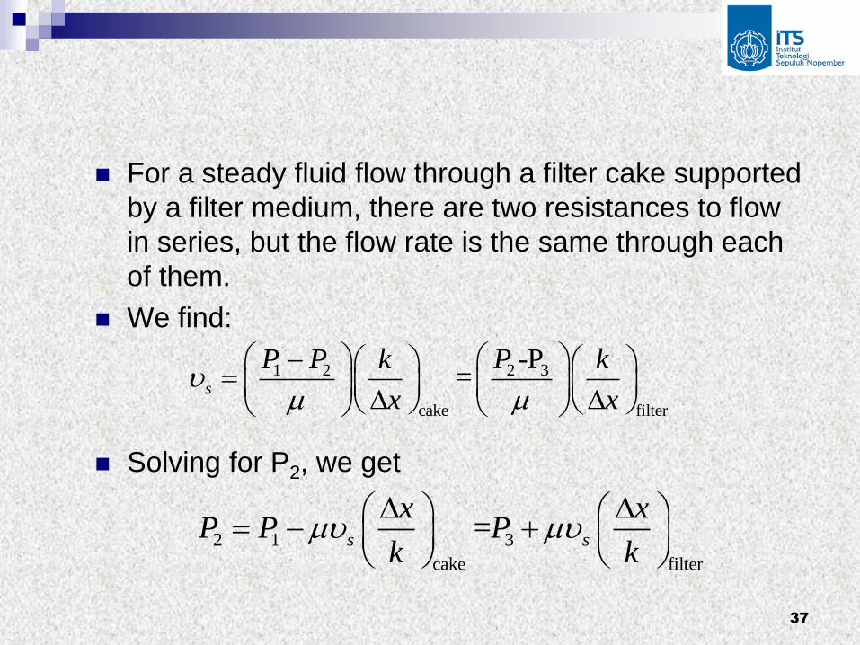
For a steady fluid flow through a filter cake supported
by a filter medium, there are two resistances to flow
in series, but the flow rate is the same through each
of them.
We find:
Solving for P2, we get
2 31 2
cake filter
-P=s
PP P k k
x x
2 1 3
cake filter
=s s
x xP P P
k k

38
Then solving for vs:
This equation describes the instantaneous flow rate
through a filter; it is analogous to Ohm’s law for two
resistors in series.
The Δx/k terms are called the cake resistance and
the cloth resistance.
1 3( ) (20)
[( / ) ( / ) ]s
cake filter filter
p p Qv
x k x k A

39
The resistance of the filter medium is usually
assumed to be a constant that is independent of time,
so (Δx/k)filter is replaced with a constant α.
If the filter cake is uniform, then its resistance is
proportional to its thickness:
1
1
cake
cake
cake
mass of cakex
area
volume of gas mass of solids removed
area volume of gas
40
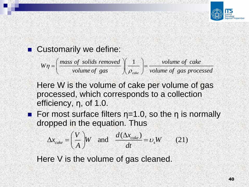
Customarily we define: Here W is the volume of cake per volume of gas processed, which corresponds to a collection efficiency, η, of 1.0.
For most surface filters η=1.0, so the η is normally dropped in the equation. Thus Here V is the volume of gas cleaned.
1
cake
mass of solids removed volume of cakeW
volume of gas volume of gas processed
( ) and (21)cake
cake s
d xVx W W
A dt

41
Substituting Eq. (21) for the cake thickness in Eq. (20), we
find
For most industrial gas filtrations the filter is supplied by a
centrifugal blower at practically constant pressure, so (P1-
P3) is a constant, and Eq. (22) may be rearranged and
integrated to
1 3(P -P )Q 1 dV= = = (22)
A A dt [(V /kA+ ]s
W
2
1 3( ) (23)2
V W VP P t
A k A
42
For many filtrations the resistance α of the
filter medium is negligible compared with
the cake resistance, so the second term of
Eq. (23) may be dropped.
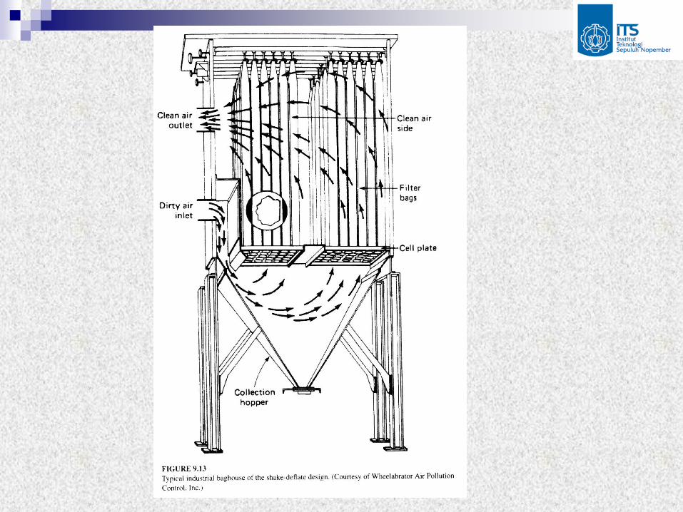
The two most widely used designs of
industrial surface filters are shown in Figs.
9.13 and 9.14 (next and second slides).

45
For the baghouse in Fig. 9.13 there must be some way
of removing the cake of particles that accumulates on
the filters.
Normally this is not done during gas-cleaning operations.
A weak flow of gas in the reverse direction may also be
added to help dislodge the cake, thus deflating the bags.
Often metal rings are sewn into filter bags at regular
intervals so that they will only partly collapse when the
flow in reversed.

46
Because it cannot filter gas while it is being cleaned, a
shake-deflate baghouse cannot serve as the sole
pollution control device for a source that produces a
continuous flow of dirty gas.
Typically, for a major continuous source like a power
plant, about five baghouses will be used in parallel,
with four operating as gas cleaners during the time
that the other one is being shaken and cleaned.
Each baghouse might operate for two hours and then
be cleaned for 10 minutes.

47
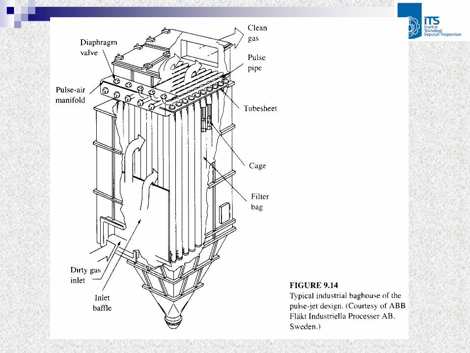
The other widely used baghouse design,
called a pulse-jet filter, is shown in Fig.
9.14.
In it the flow during filtration is inward
through the bags, which are similar to the
bags in Fig. 9.13 except their ends open at
the top.
The bags are supported by internal wire
cages to prevent their collapse.

48
The bags are cleaned by intermittent jets
of compressed air that flow into the inside
of the bag to blow the cake off.
Often these baghouses are cleaned while
they are in service.

49
Example 15
The shake-deflate baghouse on a power
station has six compartments, each with
112 bags that are 8 in. in diameter and 22
ft long, for an active area of 46 ft2 per bag.
The gas being cleaned has a flow rate of
86,240 ft3/min.
The pressure drop through a freshly
cleaned baghouse is estimated to be 0.5
in. H2O.

50
The bags are operated until the pressure
drop is 3 in. H2O, at which time they are
taken out of service and cleaned.
The cleaning frequency is once per hour.
The incoming gas has a particle loading of
13 grams/ft3.
51
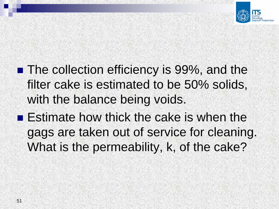
The collection efficiency is 99%, and the
filter cake is estimated to be 50% solids,
with the balance being voids.
Estimate how thick the cake is when the
gags are taken out of service for cleaning.
What is the permeability, k, of the cake?

52
Solution: The average velocity coming to the filter surface:
The 5 is used here because one of the six
compartment is always out of service for cleaning.
vs is commonly referred to as the air-to-cloth ratio,
face velocity, or superficial velocity.
3
2
86240 /3.35 1.02
(5)(112)(46 )s
Q ft min ft m
A ft min min
53
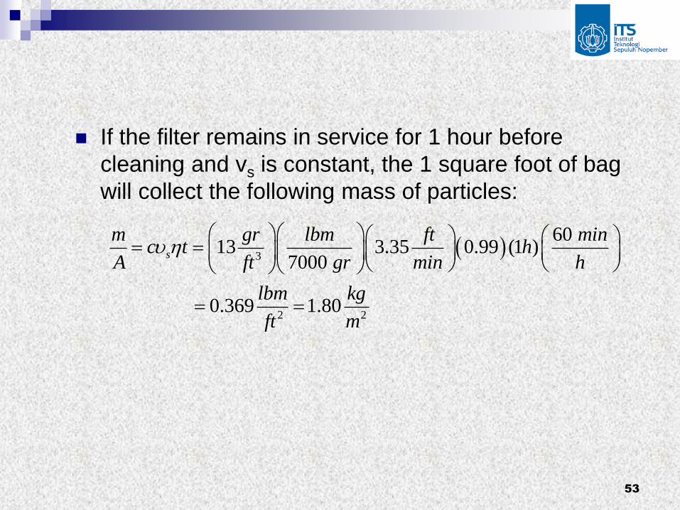
If the filter remains in service for 1 hour before
cleaning and vs is constant, the 1 square foot of bag
will collect the following mass of particles:
3
2 2
60 13 3.35 0.99 (1 )
7000
0.369 1.80
s
m gr lbm ft minc t h
A ft gr min h
lbm kg
ft m

54
The thickness of the cake collected in 1 hour is
Taking
2
3 3 3
3
/ 0.369 /
(2 / )(0.5)(62.4 / / )
5.9 10 0.071 . 1.8
m A lbm ft
g cm lbm cm ft g
ft in mm
0, we can solve Eq. (20) for k, filter
x
k
5 2
2
2 2
12 2 13 2
(3.35 / min)(0.071 /12 .)(0.018 )(2.09 10 / / )( / 60 )
( ) (3 . )(5.202 / / . )
7.96 10 7.40 10
s x ft ft in cp lbf s ft cp min sk
p in H O lbf ft in H O
ft m

55
Compare this with values found in ground water flow:
The calculated permeability of this material is roughly
the same as that of a highly permeable sandstone. #
12 2
11 2(7.96 10 ) 0.75
1.06 10
darcyk ft darcies
ft
56
This calculation shows that the collected is
about 1.8 mm thick.
If the cleaning were perfect, this would be
the cake thickness.
However, it is hard to clean the bags
completely, and in power plant operation it
is common for the average cake thickness
on the bags to be up to 10 times this
amount.

57
One of the advantages of the pulse-jet
design is that it cleans the bags more
thoroughly, allowing a higher vs, at the
cost of a somewhat shortened bag life.
Fig. 9.15 (next slide) is a set of typical
results from tests of collection efficiency
for this kind of filter.


59
If the superficial velocity increases, the
efficiency falls; for a superficial velocity of
3.35 m/min the outlet concentration is
about 20 percent of the inlet concentration.
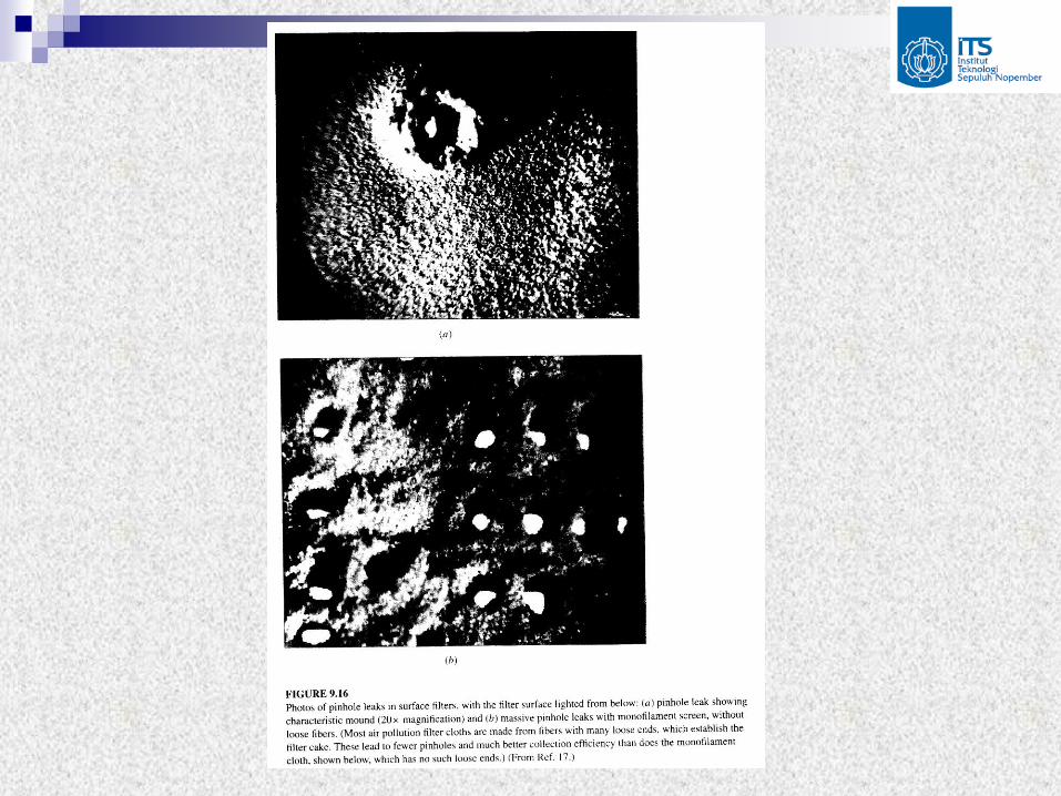
The particles that pass through such a
filter do not pass through the cake but
through pinholes, which are regions where
the cake did not establish properly (Fig.
9.16, next slide).
61
The pinholes are apparently about 100 µ
in diameter, much too large for a single
particle to block because there are rarely
100-µ particles in the streams being
treated.
When the superficial velocity is high, more
pinholes form.

62
Example 16
Estimate the velocity through a pinhole in
a filter with a pressure drop of 3 in. of
water.
Assuming that this is the pressure drop
corresponding to the curve for 0.39 m/min
on Fig. 9.15, that the steady-state
penetration at that velocity is 0.001, and
that the pinholes have a diameter of 100 µ,
estimate how many pinholes per unit area
there are in the cake.
63
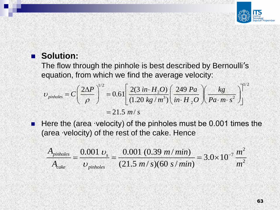
Solution: The flow through the pinhole is best described by Bernoulli’s
equation, from which we find the average velocity:
Here the (area ∙velocity) of the pinholes must be 0.001 times the
(area ∙velocity) of the rest of the cake. Hence
1/ 21/ 2
2
3 2
2
2 2(3 ) 249 0.61
(1.20 / )
21.5 /
pinholes
P in H O Pa kgC
kg m in H O Pa m s
m s
27
2
0.001 0.001 (0.39 / )3.0 10
(21.5 / )(60 / )
pinholes s
cake pinholes
A m min m
A m s s min m
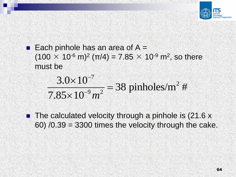
64
Each pinhole has an area of A =
(100 10-6 m)2 (π/4) = 7.85 10-9 m2, so there
must be
The calculated velocity through a pinhole is (21.6 x
60) /0.39 = 3300 times the velocity through the cake.
72
9 2
3.0 1038 pinholes/m #
7.85 10 m
65
2.2 Depth Filter
Filters do not form a coherent cake on the
surface, but instead collect particles
throughout the entire filter body are called
depth filters.
The examples with which the student is
probably familiar are the filters on filter-
tipped cigarettes and the lint filters on
many home furnaces.

66
In both of these a mass of randomly
oriented fibers (not woven to form a single
surface) collects particles as the gas
passes through it.
In Fig. 9.17 (next slide), we see a particle-
laden gas flowing toward a target, which
we may think of as a cylindrical fiber in a
filter.
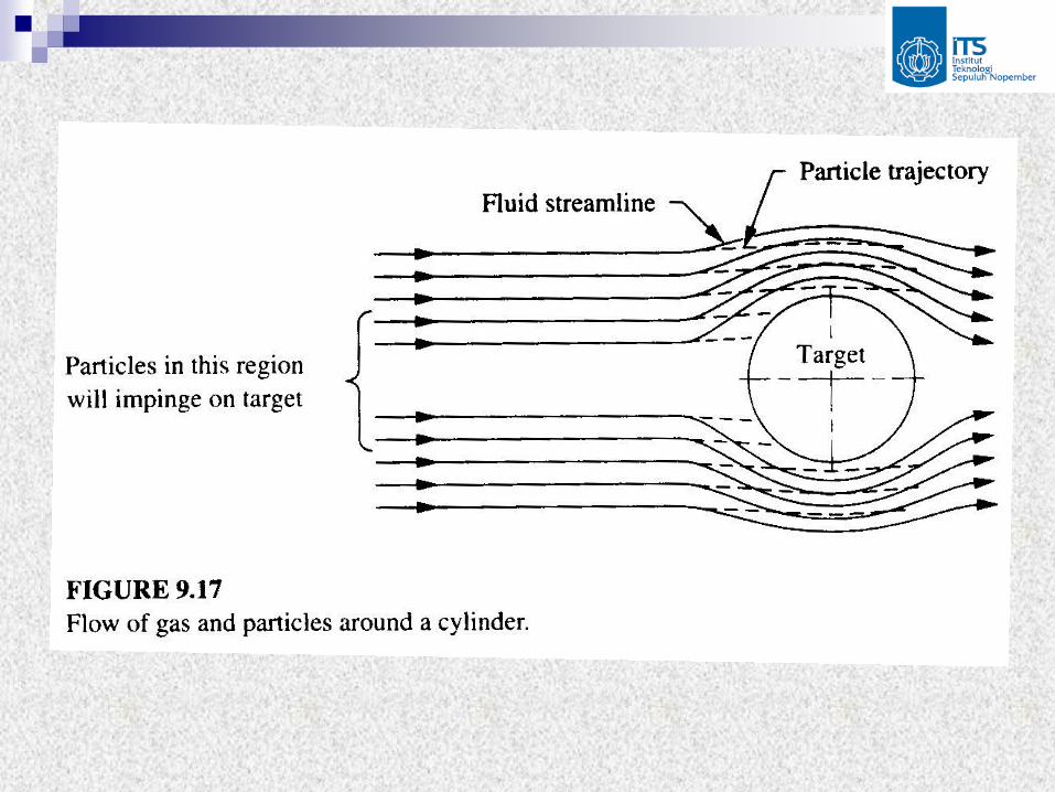

68
To determine whether a particle bumps
into the target or flows around it, we can
compute the relative velocity between
particle and gas using the appropriate
equivalents of Stokes’ law.
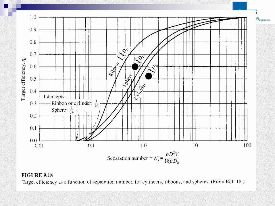
That task was first undertaken by
Langmuir and Blodgett, and Fig. 9.18 (next
slide) conveniently summarizes the
mathematical solutions for the small
particles of interest in air pollution work.

70
To see how they obtained Fig. 9.18,
consider a single particle in a turning part
of the gas stream as shown in Fig. 9.19
(next slide).
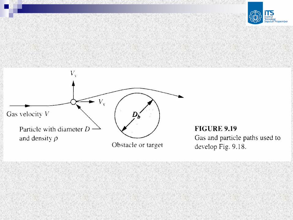

72
In Fig. 9.19, the appropriate velocity to use in Stokes’ law is not the overall stream velocity but rather the
difference in y-directed velocity between the particle
and the gas stream.
Generally, the gas stream will have a larger velocity
in this direction than the particle, so
3 ( )y drag y gas y particleF D

73
The resisting (inertial) force of the particle is
If there are no electrostatic, magnetic, or other forces
acting, then these two forces are equal and opposite,
so
3
6
y particle
y inertial
dF ma D
dt
2
18 ( )y particle y gas y particled
dt D
74
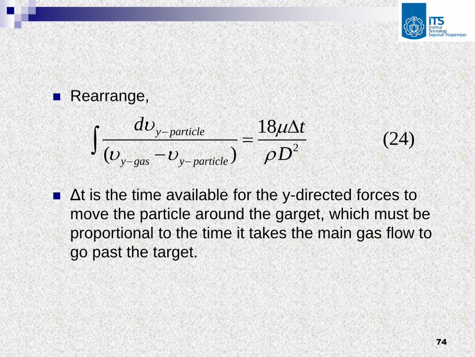
Rearrange,
Δt is the time available for the y-directed forces to
move the particle around the garget, which must be
proportional to the time it takes the main gas flow to
go past the target.
2
18 (24)
( )
y particle
y gas y particle
d t
D

75
This time = Db/v, where Db is the diameter of the
barrier, so we may substitute in Eq. (24), finding
Ns is the separation number, which appears on the
horizontal axis in Fig. 9.18.
It is equal to the diameter of the barrier divided by
the stokes stopping distance.
2
12
18 1 (25)
( )
y y particle b
yy gas y particle s
d D
D N

76
Some authors call Ns the impaction
parameter or inertial parameter.
In Eq. (25) we can see that if the integral
on the left is a large number (a low value
of Ns), then there is plenty of time and
force for the flow to move the particle
around the target and the target efficiency
(ηt) will be low.

77
Example 17
A single, cylindrical fiber 10 µ in diameter
is placed perpendicular to a gas stream
that is moving at 1 m/s.
The gas stream contains particles that are
1 µ in diameter and the particle
concentration is 1 mg/m3.
What is the rate of collection of particles
on the fiber?

78
Solution: If all the particles that start moving directly toward the
fiber hit it, then the collection rate would be equal to
the volumetric flow rate approaching the fiber times
the concentration of particles:
If we catch them all, we will collect 10-8 g/s for every
meter of fiber length.
5 3 3
8
maximum possible rate = (1 / )(10 )(10 / )
10 / /
bD c m s m g m
g m s

79
The actual amount caught will be this number times
the target efficiency.
The separation number is
From Fig. 9.18, we see that for cylinders this value of
Ns corresponds to a target efficiency of about 0.42,
so we would expect to collect about 0.42 10-8
g/m/s. #
3 6 2
5 5
(2000 / )(10 ) (1 / )0.617
(18)(1.8 10 / / )(10 )s
kg m m m sN
kg m s m

80
Example 18
A filter consists of a row of parallel fibers across a flow, as described in Example 17, with the center-to-center spacing of the fibers equal to five fiber diameters.
What collection efficiency will the filter have for the particles?
Assume that the fibers are far enough apart that each one behaves as if it were in an infinite fluid, uninfluenced by the other fibers.
81
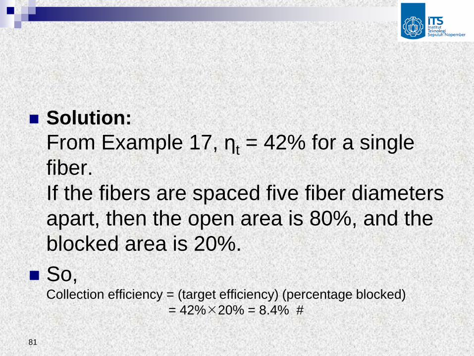
Solution:
From Example 17, ηt = 42% for a single
fiber.
If the fibers are spaced five fiber diameters
apart, then the open area is 80%, and the
blocked area is 20%.
So, Collection efficiency = (target efficiency) (percentage blocked)
= 42%20% = 8.4% #
82
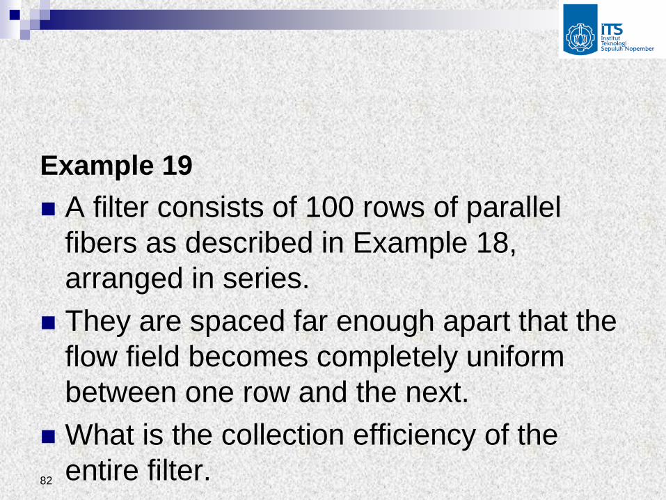
Example 19
A filter consists of 100 rows of parallel
fibers as described in Example 18,
arranged in series.
They are spaced far enough apart that the
flow field becomes completely uniform
between one row and the next.
What is the collection efficiency of the
entire filter.

83
Solution:
ηoverall = 1 - poverall = 1 - (pindividual)n
= 1 - (1-0.084)100 = 0.9998 #
These three examples show, in idealized
form, what goes on within depth filters.
Most such filters do not have an orderly
array of parallel fibers; the filter medium
consists of a tangled jumble of fibers in a
random orientation, making up a thick mat.

84
In depth filters that diffusion leads to small
particle collection in addition to that
computed above by impaction.
Friedlander developed a theoretical
equation, with constants determined by
experiment, for the case of diffusion
collection of particles from a gas steam
flowing past a cylinder under
circumstances where impaction was
negligible.

85
Most of the published data could be represented by
where all the terms are as defined previously, Di is
the diffusivity and ν is the kinematic viscosity.
The first term on the right is for diffusion collection,
where as the second is for collection by noninertial
contact (interception)
2/3 2 1/ 2
1/ 2 3/ 21/ 6 1/ 2 1/ 2
6 3 (26)i
t
b b
D D
D D
86
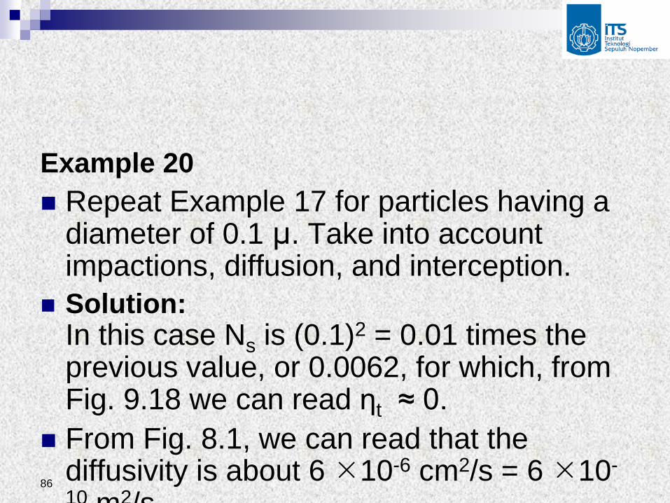
Example 20
Repeat Example 17 for particles having a diameter of 0.1 µ. Take into account impactions, diffusion, and interception.
Solution: In this case Ns is (0.1)2 = 0.01 times the previous value, or 0.0062, for which, from Fig. 9.18 we can read ηt ≈ 0.
From Fig. 8.1, we can read that the diffusivity is about 6 10-6 cm2/s = 6 10-
10 m2/s.

87
So
The diffusion term is (0.0086 / 0.00025) = 34.4 times
the interception term.
Table 9.3 (next slide) shows the effect of changes in
velocity and particle diameter on the collection
mechanisms.
10 2 2/3 7 2 1/ 2
5 2 5 1/ 2 1/ 2 5 2 1/ 2 5 3/ 2
6(6 10 / ) 3(10 ) (1 / )
(1.49 10 / )(10 ) (1 / ) (1.49 10 / ) (10 )
0.0086 0.00025 0.0088 0.9% #
t
m s m m s
m s m m s m s m


89
There is some particle size at which there
is a minimum collection efficiency.
Typically, this size is in the range 0.1 to 1
µ, which is the size most likely to be
deposited in the human lung.
90
2.3 Filter Media
For shake-deflate baghouses, the filter
bags are made of tightly woven fibers
(surface filter), much like those in a pair of
jeans.
Pulse-jet baghouses use high strength
felted fabrics, so that they act partly as
depth filters and partly as surface filters.
91
Filter Fabrics are made of cotton, wool,
glass fibers, and a variety of synthetic
fibers.
Cotton and wool cannot be used above
180 and 200oF, respectively, without rapid
deterioration, whereas glass can be used
to 500oF (and short-time excursions to
550oF).

92
In addition the fibers must be resistant to
acids or alkalis if these are present in the
gas stream or the particles as well as to
flexing wear caused by the repeated
cleaning.
Typical bag service life is 3 to 5 years.


Sumber:
Control of Primary Particulates by Hsin Chu, Professor, Dept. of Environmental Engineering, National Cheng Kung University, Taiwan
Technology for Air Pollution Control by NN


![Fabric Filter Bag Cleaning[0].pdf](https://static.fdocuments.us/doc/165x107/55cf9932550346d0339c207a/fabric-filter-bag-cleaning0pdf.jpg)