FABCO-AIR INC. QUICK INDEX 0 Specials · Fabco-Air Inc. Specials 0 ii Specials... Consider asking...
198
FABCO-AIR INC. QUICK INDEX 0 1 2 3 4 5 6 7 8 9 10 11 12 13 14 15 Mini-Pancake ® Pancake ® The Pancake Line ® Pancaked ® Pancaked Pneumatics ® Multi-Power ® Square 1 ® Dial-A-Stroke ® are registered trademarks of FABCO-AIR INC. Longstroke™ Hi-Power™ Micro-Fine™ Pro-Coat™ Hexless™ Super-Vee™ Pneu-Grip™ Mini-Grip™ are trademarks of FABCO-AIR INC. Delrin ® is a registered trademark of DuPont Corp. Duralon ® is a registered trademark of Rexnord Corp. Loctite ® is a registered trademark of Loctite Corp. Magnalube ® -G is a registered trademark of Carleton Stuart Corp. Poly Pak ® is a registered trademark of Parker Hannifin Corp. Teflon ® is a registered trademark of DuPont Corp. Viton ® is a registered trademark of DuPont Corp. i 3-4-08 Specials Square 1 ® Cylinders Longstroke™ Cylinders Hi-Power™Cylinders Multi-Power ® Air Presses See Catalog #FP-16 Piston Position Sensors – now included within each cylinder section Air-Oil Tanks Pneu-Grip™ Grippers See Catalog #GR-8 Directional Control Valves Needle & Flow Control Valves Special Purpose Valves Breathers and Mufflers Vacuum Generators Multi-Power ® Boosters Multi-Power ® Cylinders Pancake ® Cylinders 16 Hard Wired Solenoid Connectors
Transcript of FABCO-AIR INC. QUICK INDEX 0 Specials · Fabco-Air Inc. Specials 0 ii Specials... Consider asking...
FABCO-AIR INC. QUICK INDEX 0
1
2
3
4
5
6
7
8
9
10
11
12
13
14
15
Mini-Pancake ®
Pancake ®
The Pancake Line ®
Pancaked ®
Pancaked Pneumatics ®
Multi-Power ®
Square 1 ®
Dial-A-Stroke ®
are registered trademarks of FABCO-AIR INC.
Longstroke™
Hi-Power™
Micro-Fine™
Pro-Coat™
Hexless™
Super-Vee™
Pneu-Grip™
Mini-Grip™
are trademarks of FABCO-AIR INC.
Delrin® is a registered trademark of DuPont Corp.
Duralon® is a registered trademark of Rexnord Corp.
Loctite® is a registered trademark of Loctite Corp.
Magnalube®-G is a registered trademark of Carleton Stuart Corp.
Poly Pak® is a registered trademark of Parker Hannifin Corp.
Teflon® is a registered trademark of DuPont Corp.
Viton® is a registered trademark of DuPont Corp.
i3-4-08
Specials
Square 1® Cylinders
Longstroke™ Cylinders
Hi-Power™Cylinders
Multi-Power® Air PressesSee Catalog #FP-16
Piston Position Sensors – now included within each cylinder section
Air-Oil Tanks
Pneu-Grip™ GrippersSee Catalog #GR-8
Directional Control Valves
Needle & Flow Control Valves
Special Purpose Valves
Breathers and Mufflers
Vacuum Generators
Multi-Power® Boosters
Multi-Power® Cylinders
Pancake® Cylinders
16Hard Wired Solenoid Connectors
Fabco-Air Inc. Specials0
ii
Specials...Consider asking Fabco-Air for a modified or special product to meet your necessary and specific re-quirements. Fabco-Air has the willingness, years of experience, manpower and equipment available to design, adapt, modify and produce in any quantity, existing or new products to meet your job require-ments more effectively. Please contact your local distributor with details of your requirements so that we may assist you.
The photos here show just a few examples of the thousands of specials that have been produced over the past three decades.
1/2 NPT Valve Stack■ Manifolded inlet into both valves ■ One solenoid controlled valve with internal orificing to pilot operate second valve
Pancake®
■ Rear tapped mount with extension hub
Pancake®
■ Heavy spring extend ■ Front flange mount
1/2 NPT Valve■ 3 way with heavy spring ■ Provision for operator at-tachment and positive manual override for foot opera-tion
Pancake®
■ 3 position
6/15/05
Fabco-Air Inc. Specials0
iii
Pancake®
■ Double rods with hole through concentric shafts and independent ports for stripper control
Modular Valve Bank■ Stacked with mounting brackets ■ Swivel flow controls ■ Fittings ■ Wire terminals ■ Wire insulation installed
Hi-Power™■ Double rod ■ oversized rods ■ Oversized hole through
Longstroke® Pivot Mount■ 2 stage Multi-Power® principle
Square 1®
■ 2 stage Multi-Power® principle
Pancake®
■ 2 stage Multi-Power® principle
6/15/05

1
Pancake® Cylinders
Specifications subject to change without notice or incurring obligation1.1
Page
Features & Benefits ......................................................................... 1.2
General, Standard Specifications .................................................... 1.2
Construction Details ........................................................................ 1.3, 1.4 How a Pancake® is built
Action Information ............................................................................ 1.5, 1.6 How a Pancake® Functions
Option Information ........................................................................... 1.7 - 1.14, 1.65, 1.66 Description of Options
Custom Options and Specials ......................................................... 1.15
Air Spring ......................................................................................... 1.15
Accessories Flow Controls, Port Mounted and Others............................. 1.16 Position Sensors .................................................................. 1.14, 1.16 Mounting Bolts .................................................................... 1.16 Wrench Flat Wrench ........................................................... 1.16
Detailed Specification Model Number Codes How to Order Standard Dimensions Seal Kit Part Numbers Magnetic Piston Position Sensing Option Dimensions 1/2" (5) Bore ............................................. 1.17 - 1.22 3/4" (7) Bore ............................................. 1.23 - 1.28 1-1/8" (121) Bore ............................................. 1.29 - 1.34 1-5/8" (221) Bore ............................................. 1.35 - 1.40 2" (321) Bore ............................................. 1.41 - 1.46 2-1/2" (521) Bore ............................................. 1.47 - 1.52 3" (721) Bore ............................................. 1.53 - 1.58 4" (1221) Bore ............................................. 1.59 - 1.64
Flow Controls Port Mounted and Others .................................................... Section 12
Specials ........................................................................................ ii, iii
2 Year Warranty ............................................................................... Inside back cover
Section 1 Index Original & “T” Series8 Bores, 1/2" – 4"
4-22-04

1
Specifications subject to change without notice or incurring obligation
Pancake® Cylinders
1.24-22-04
Features Benefits. . . . . . .
. . . . . . . . . . . . . . . .
. . . . . . . . . . . . .
® nonmetallic rod bushing . . . . . . . .
stainless steel piston rod . . . . . . . . . . . . . . .
. . . . . . . . . . . . . .
. . . . . . . . . . . .
. . . . . . . . . . . . . . . . . . . . . . .
. . . . . . . .
®-G Grease . . . . .
. . . . . . . . . . . . . . . . . . . . . . . . . . .
. . . . . . . . . . . . . . . . . . . . . . .
General, Standard SpecificationsMedia . . . . . . . . . . . . . . . . . . . . . . . Air . . . . . . . Optional - Hydraulic
. . . . . 250 psi . . . . Optional - 500 psiMinimum operating pressure . . . . . See page 1.4, Item 4Ambient & media temperature . . . . –25° to + 250°FPrelubrication . . . . . . . . . . . . . . . . . Magnalube®-G GreaseAir line lubrication . . . . . . . . . . . . . . RecommendedStroke tolerance . . . . . . . . . . . . . . ± 1/64"
Original & “T” Series8 Bores, 1/2" – 4" Features & Benefits
Original Series
Original Series
Original Series, Nonrotating
Laboratory tests confirm that internally lubricated Buna-N O-ring seals have extended Pancake® cylinder life 2 to 3 times beyond that of cylinders using standard Buna-N seals.
Pancake® Cylinder, was designed in 1958 to satisfy the need for short stroke cylinders that would fit in very tight
of cylinder applications around the world, The Pancake® Line offers you far more than any of its imitators – more features and options – better quality, strength and appearance – and far longer product life!
We are so confident in our design and manufacturing skills that we back every Pancake® Cylinder with our 2-year Warranty!

1
Pancake® Cylinders
Specifications subject to change without notice or incurring obligation4-1-08
Construction Details
9
419 10
6 57 4
8
1
Single Rod – Double ActingAction - X
1/2" & 3/4" Bores
6 4
10
12
19
41019
19
413
Double Rod – Double ActingAction - XDR
1/2" & 3/4" Bores
6 5
8
1
9
419
4
10
7 14
Single Rod – Double ActingAction - X
1/2" & 3/4" Bores
2
1
4
4
103
18
9
15
8
716
56
2
1
4
14
103
18
9
15
716 5
4
8
6
1.3
2
1
4
4
103
9
78
56
2
1
4
14
103
9
78 5
46
2
1
4103
9
12
6
4
4
10
3
13
11
Double Rod – Double ActingAction - XDR
Single Rod – Double Acting – NonrotatingAction - XK
Single Rod – Double ActingAction - X
Single Rod – Double Acting – NonrotatingAction - XK
Single Rod – Double ActingAction - X
“T” Series (PTFE Piston Bearing)
Original & “T” Series8 Bores, 1/2" – 4"
Original Series
Single Rod - Double ActingAction -X shown

1
Specifications subject to change without notice or incurring obligation
Pancake® Cylinders
1. forces.
2.
rigidity, and piston rod support. Machining all surfaces provides per-pendicularity and concentricity for locating, mounting, and making attachments to the rod. It also presents a clean, smooth, "no-dirt-catching" appearance on your machine.
3. Unique construction provides unequalled piston rod support and
lined fiberglass structure with a load carrying capacity of 60,000 psi.
psi, and porous iron at 8,000 psi. Duralon also provides: CONSIS-
-
length is increased as the stroke increases, providing even more piston rod support.
4. Internally lubricated Buna-N O'Rings (-25° to + 250°F) provide low profile, low friction, and long life sealing of piston and rod. All static seals are Buna-N.
and lower breakaway (starting) and running friction and smoother operation. In tests, cylinders with internally lubricated O'Rings have
-
cylinders with internally lubricated O'Rings under no-load conditions -
tions of options, breakaway pressures may vary.
Bore Number 5 7 121 221 321 521 721 1221Bore, Inches 1/2 3/4 1-1/8 1-5/8 2 2-1/2 3 4Breakaway psi 12.0 6.5 4.5 4.5 4.0 3.0 3.0 2.5
Operating Media in many applications. 1.0 psi is the equivalent of 2.04"
5. overall height as short as possible. Please note that any cylinder offering less height than that of a Pancake® with the same stroke, sacrifices rod bushing length and/or overall strength.
6. for strength, rigidity, ease of modification for specific application require-ments, and ease of access for maintenance should it be required.
7.
® on the threads and faces assures sealing and locks the assembly against pounding and vibration.
8. and control of concentricity between piston rod and piston O.D.
2-13-08 1.4
Original & “T” Series8 Bores, 1/2" – 4"
9. Polishing the cylinder bore and piston rod produces a fine
finish, provides a place for lubrication to lie and support the seal as
lower friction and longer seal life.
10. plated (68-72 Rc) stainless steel. Surface finish is 12 RMS or better
combined with the low friction and high load capacity of the Duralon®
11. A pilot diameter on the cover is concentric with the rod bushing and locates in the cylinder bore to maintain the concentricity, precision, and rigidity of the Pancake® design.
12. Counterbores on both sides of the piston maintain concentric-
13.
is torqued for proper preload of the stud and clamping of the piston ® on the threads and faces assures sealing and locks
be pounded loose.
14.-
ance, rectangular cross section strip of a tough, stable, wear resistant
misalignment or other forces, this bearing, along with the long and rigid Duralon® rod bushing, supports the load and helps to maintain the long life of the cylinder bore and O-ring seal. Note: the bearing is not included, or required in double rod models because the long rod bushings at each end of the cylinder provide superb support.
15.
provides protection from the environment and from physical damage.
is required and the rod end is left free for attachments and tooling as required by the application. An information label, similar to this one, is applied to each cylinder to warn against damage.
WARNING
16.
combination provides no leak, precision guiding and long life.
18. A disk of rubber is included at the end of the guide pins to take up play and firmly seat the pins in the precision machined guide pin holes.
19piston rod seal O-ring is located as close to the outer end as feasible so that as much of the bearing as possible gets system lubrication as well as protecting most of the bearing length from the environment. A precision machined pilot diameter locates the cylinder bore to assure concentricity and proper rod alignment.
Nearly 4 decades of experience paying close attention to design detail, production and assembly techniques have resulted in the ultimate Fabco-Air Pancake®, short stroke cylinders. Pancakes® fit into very tight spaces and virtually ANY short stroke cylinder application. Think how well they will fit with your application!
Construction Details

1
Pancake® Cylinders
Specifications subject to change without notice or incurring obligation1.5
C-221-X X
C-221-XK XK
C-221-O O
C-221-OP OP
“T” SeriesPTFE Piston BearingOriginal Series Action Letter
Action Description
Action -X
Single Rod Double Acting
One Piston Rod
NFPASymbol
Action -XK
Single Rod Double ActingNonrotating
One Piston Rod
Piston guide pins for nonrotating
Action -O
Single Rod Single Acting - Spring Retracted
One Piston Rod
Action -OP
Single Rod
One Piston Rod
4-22-04
Action InformationOriginal & “T” Series8 Bores, 1/2" – 4"

1
Specifications subject to change without notice or incurring obligation
Pancake® Cylinders
1.6
C-221-XDR
C-221-XDRK
C-221-ODR
4-8-04
“T” SeriesPTFE Piston BearingOriginal Series Action Letter
Action DescriptionNFPA
Symbol
Action -XDR
Double Rod Double Acting
Action -XDRK
Double Rod Double ActingNonrotating
Piston guide pins for nonrotating
Action -ODR
Double Rod Single Acting - Spring Retracted
in the double rod version.
superb rod support
in the double rod version.
superb rod support
in the double rod version.
superb rod support
® Model Number specifies how many piston rods the cylinder has (Single Rod or Double Rod), how the piston rod is
restricted from rotating by internal guide pins (Nonrotating).
Action InformationOriginal & “T” Series8 Bores, 1/2" – 4"

1
Pancake® Cylinders
Specifications subject to change without notice or incurring obligation1.7
Option InformationOriginal & “T” Series8 Bores, 1/2" – 4"
4-23-04
METRIC M
-MR
PREFIX OPTIONS
PREFIX
PREFIX OPTIONS
bore and larger are G1/8 with 14mm spotface for 1/8 BSP-Parallel fittings and gaskets.
Available on all series, bore, stroke and action combinations.
See Option Specifications pages of desired bore and action for complete dimensional details.
1
Specifications subject to change without notice or incurring obligation
Pancake® Cylinders
1.8
Option InformationOriginal & “T” Series8 Bores, 1/2" – 4"
4-23-04
MALE ROD THREADSingle Rod -MR
-MR-MR1-MR2
SUFFIX OPTIONSSUFFIX
A high strength stud is threaded into the standard female rod end and ®
provides a much stronger rod end which can be repaired, rather than replacing the complete rod, should the thread be damaged.
Available on all series, bore, stroke and action combinations.
See Option Specifications pages of desired bore and action for complete dimensional details.
SUFFIX OPTIONS
TEFLON® (+400° to +500° F) -T
VITON® (-15° to +400° F) -V
QUAD (-30° to +250° F) -Q
NONROTATING Single Acting -NR
For Double Acting, NonrotatingSEE Action -XK, -XDRKon pages 1.5 and 1.6
aluminum endcap replaces the round rod in Single Acting, Spring Retracted (Actions -O, -ODR) cylinders.
Available in all series, bores 1/2" (5), 3/4" (7), all strokes, actions -O, -ODR.
See Option Specifications pages of desired bore and action for complete dimensional details.
A QUAD seal replaces the standard O'Ring on the piston only. Standard seal material is Buna-N (-30° to +250°F). For other materials consult engineering.
Available on all series, bore, stroke and action combinations.
See Standard Specifications pages of desired bore and action
from standard.
medias. Consult engineering for compatibility information.
Available on all series, bore, stroke and action combinations.
See Standard Specifications pages of desired bore and action
from standard.
For elevated temperatures (+400° to +500° F) or compatibility with
NOT
applications that require thermal cycling over wide temperature ranges.
Available on all series, bores 1-1/8" (121) and larger, all strokes and actions -X, -XDR.
See Standard Specifications pages of desired bore and action
from standard.
1
Pancake® Cylinders
Specifications subject to change without notice or incurring obligation1.9
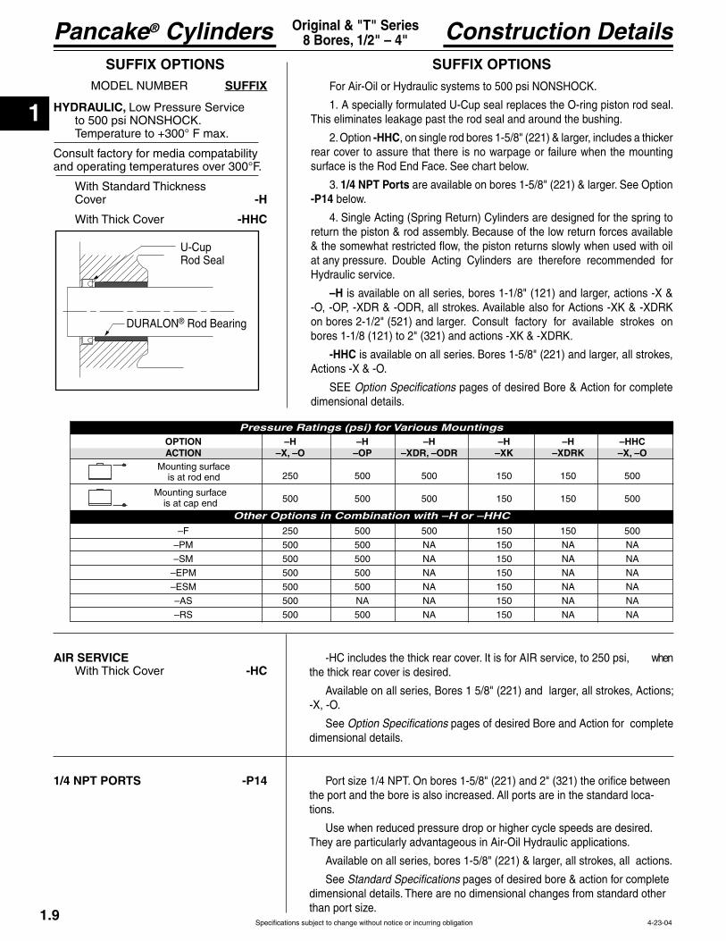
Construction DetailsOriginal & "T" Series8 Bores, 1/2" – 4"
HYDRAULIC, to 500 psi NONSHOCK.
Consult factory for media compatability and operating temperatures over 300°F.
Cover -H
-HHC
SUFFIX OPTIONSFor Air-Oil or Hydraulic systems to 500 psi NONSHOCK.
1. A specially formulated U-Cup seal replaces the O-ring piston rod seal.
2. Option -HHC, on single rod bores 1-5/8" (221) & larger, includes a thicker rear cover to assure that there is no warpage or failure when the mounting
3. 1/4 NPT Ports are available on bores 1-5/8" (221) & larger. See Option -P14 below.
4. Single Acting (Spring Return) Cylinders are designed for the spring to return the piston & rod assembly. Because of the low return forces available
at any pressure. Double Acting Cylinders are therefore recommended for Hydraulic service.
–H is available on all series, bores 1-1/8" (121) and larger, actions -X & -O, -OP, -XDR & -ODR, all strokes. Available also for Actions -XK & -XDRK on bores 2-1/2" (521) and larger. Consult factory for available strokes on bores 1-1/8 (121) to 2" (321) and actions -XK & -XDRK.
-HHC is available on all series. Bores 1-5/8" (221) and larger, all strokes, Actions -X & -O.
Option Specifications pages of desired Bore & Action for complete dimensional details.
U-CupRod Seal
® Rod Bearing
SUFFIX OPTIONS SUFFIX
OPTION –H –H –H –H –H –HHC ACTION –X, –O –OP –XDR, –ODR –XK –XDRK –X, –O
250 500 500 150 150 500
500 500 500 150 150 500
–F 250 500 500 150 150 500
–PM 500 500 NA 150 NA NA
–SM 500 500 NA 150 NA NA
–AS 500 NA NA 150 NA NA
–RS 500 500 NA 150 NA NA
Mounting surface is at rod end
Mounting surface is at cap end
Pressure Ratings (psi) for Various Mountings
Other Options in Combination with –H or –HHC
-HC includes the thick rear cover. It is for AIR service, to 250 psi, when the thick rear cover is desired.
-X, -O.
See Option Specifications pages of desired Bore and Action for complete dimensional details.
AIR SERVICE -HC
1/4 NPT PORTS -P14
4-23-04
the port and the bore is also increased. All ports are in the standard loca-tions.
Use when reduced pressure drop or higher cycle speeds are desired.
Available on all series, bores 1-5/8" (221) & larger, all strokes, all actions.
See Standard Specifications pages of desired bore & action for complete

1
Specifications subject to change without notice or incurring obligation
Pancake® Cylinders
1.10
SUFFIX OPTIONS150 psi maximum operating pressure
A hole is drilled through the piston rods & the double rod stud (see -
construction is needed (for compatibility or higher pressure) see "One Piece Piston & Rod Construction" under Custom Options on page 1.15.
Insert the SUFFIX Number into the Model Number immediately after the
-ODR.
See Standard Specifications pages of desired Bore & Action for complete
SUFFIX OPTIONS
Option InformationOriginal & "T" Series8 Bores, 1/2" – 4"
HOLE THRU Double Rod Shaft
Standard Standard Plus Model No. Model No.
Bore thru stud (Std) thru stud (Std Plus) 1/2", 3/4" 1/16 -06 – – 1-1/8" 1/8 -13 5/32 -16 1-5/8" 1/8 -13 1/4 -25 2" 5/32 -16 5/16 -31 2-1/2" 5/32 -16 1/4 -25 3" 5/32 -16 1/4 -25 4" 1/4 -25 – –
-
Standard Specifications pages of desired Bore & Action for complete dimensional details.
Rod Units increases by amount stroke is shortened.
Stroke Collar
2-13-08
Pro-Coat™wear resistant coating. It will often suffice for applications where stainless steel is specified. Its lasting luster provides high visual appeal.
the nickel deposit is consistent over the entire surface. Blind holes, threads, small diameter holes and internal surfaces all receive the same amount of plating. It has natural lubricity and a high resistance to abrasion. As shipped
consult engineering.
Besides cylinder parts, Pro-Coat™ may be applied to valve bodies, solenoid housings, fittings and most any item that appears in this catalog.
Pro-Coat™ is available on all series, bore, stroke and action combina-tions.
See Standard Specifications pages of desired bore and action for complete
FINISH:
Plating: Pro-Coat™-N
RodRod
Piston Stud
STROKE COLLAR
on Piston Rod in 1/8" increments.
1) longest stroke. 2) Select the amount the stroke is to be shortened. 3) Specify the corresponding SUFFIX designation.
1/8" -C11/4" -C23/8" -C3 1/2" -C45/8" -C5 3/4" -C67/8" -C7
1
Pancake® Cylinders
Specifications subject to change without notice or incurring obligation
Option InformationOriginal & "T" Series8 Bores, 1/2" – 4"
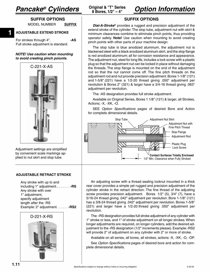
ADJUSTABLE EXTEND STROKE
For strokes through 4". -ASFull stroke adjustment is standard.
SUFFIX OPTIONSSUFFIX
SUFFIX OPTIONSDial-A-Stroke® provides a rugged and precision adjustment of the
minimum clearances combine to eliminate pinch points, thus providing operator safety. Note! Use caution when mounting to avoid creating pinch points with other parts of your machine design.
plug so that the adjustment nut can be locked in place without damaging
adjustment rod and nut provide precision adjustment. Bores 1-1/8" (121) and 1-5/8" (221) have a 1/2-20 thread giving .050" adjustment per revolution & Bores 2" (321) & larger have a 3/4-16 thread giving .063" adjustment per revolution.
Available on Original Series, Bores 1 1/8" (121) & larger, all Strokes,
Option Specifications pages of desired Bore and Action for complete dimensional details.
Contact Surfaces Totally Enclosed
Adjustment Rod
Adjustment Nut with
Stop Flange
Plastic Plug
Adjustment Nut Skirt
1/2" Min. Clearance when Fully Stroked
1.114-23-04
C-221-X-AS
NOTE! Use caution when mounting to avoid creating pinch poiunts.
Adjustment settings are simplified by convenient scale markings ap-plied to nut skirt and stop tube.
ADJUSTABLE RETRACT STROKE
Any stroke with up to and including 1" adjustment.. . . . . . . -RSAny stroke with over 1" adjustment, specify adjustmentlength after the -RS
. . . . . -RS2
An adjusting screw with a thread sealing locknut mounted in a thick rear cover provides a simple yet rugged and precision adjustment of the
screw provides precision adjustment. Bores 1/2" (5), 3/4" (7), have a 5/16-24 thread giving .042" adjustment per revolution. Bore 1-1/8" (121) has a 3/8-24 thread giving .042" adjustment per revolution. Bores 1-5/8" (221) and larger have a 1/2-20 thread giving .050" adjustment per revolution.
1" stroke or less, and 1" of stroke adjustment on all longer strokes. When longer adjustments are required, on longer cylinders, add the desired ad-
will provide 2" of adjustment on any cylinder with 2" or more of stroke.
Available on all series, all bores, all strokes, actions -X, -XK, -O, -OP.
See Option Specifications pages of desired bore and action for com-plete dimensional details.
D-221-X-RS

1
Specifications subject to change without notice or incurring obligation
Pancake® Cylinders
1.124-23-04
Option InformationOriginal & "T" Series8 Bores, 1/2" – 4"
SOUND LIMITERS
-LF-LR-LFR
SUFFIX OPTIONSSUFFIX
RUBBER BUMPERS
-BF-BR-BFR
Rubber
Standard rubber mass provided will compress and give full stroke at 60-80 psi.Mass can be adjusted to meet your specific pressure and/or dynamic load requirements
SoundLimitingO'RingCushion
A rubber doughnut is bonded to the cylinder head to act as the piston
energy, thus reducing destruction of the cylinder and tooling due to
stop is designed to compress and allow full stroke of the cylinder at 60 to 80 psi. If your application uses lower pressure or has high energy, consult engineering with application details so that rubber mass can be adjusted to meet your specific requirements.
On applications such as punching, shearing, etc., where high forces are -
point of breakthrough the piston is very close to or touching the bumper.
to absorb. It is highly recommended that shock absorbers be considered and built into the tooling to assist in absorbing the force and dynamic loads generated in such applications.
Because of the temperature limitations of the adhesives involved (-25° to + 220°F) Rubber Bumpers are available in cylinders with standard internally lubricated Buna-N seals only.
Use to reduce noise and absorb impact.
the piston and rod assembly and will not significantly compress the rub-ber bumpers.
Available on all series, all bores, all strokes, actions -X, -XK, -O (Cap end only, -BR), -OP (Rod end only, -BF), -XDR, XDRK, -ODR (Cap end only -BR).
See Standard Specifications pages of desired bore and action for
standard.
For applications where you need a small amount of cushion at the
and/or in the rear cover so that initial contact is with the elastomer and not metal-to-metal.
allow full stroke.
Because of the temperature limitations of the adhesives involved, sound limiters are available in cylinders with internally lubricated Buna-N O'Rings only.
Available on all series, all bores, all strokes, actions -X, -O (Cap end
See Standard Specifications pages of desired bore and action
standard.
SUFFIX OPTIONS
1
Pancake® Cylinders
Specifications subject to change without notice or incurring obligation1.13
Option InformationOriginal & "T" Series8 Bores, 1/2" – 4"
SUFFIX OPTIONS
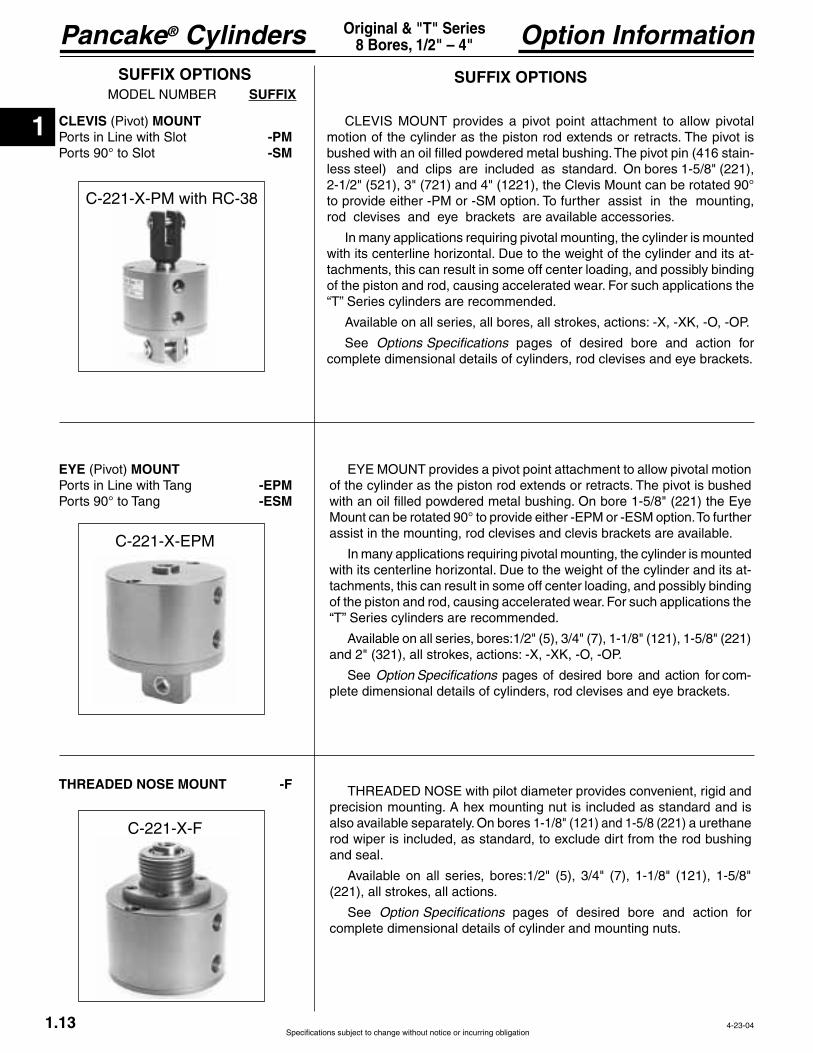
CLEVIS (Pivot) MOUNT-PM
Ports 90° to Slot -SM
SUFFIX OPTIONSSUFFIX
C-221-X-PM with RC-38
C-221-X-F
EYE (Pivot) MOUNT-EPM-ESM
THREADED NOSE MOUNT -F
also available separately. On bores 1-1/8" (121) and 1-5/8 (221) a urethane
and seal.
Available on all series, bores:1/2" (5), 3/4" (7), 1-1/8" (121), 1-5/8" (221), all strokes, all actions.
See Option Specifications pages of desired bore and action for complete dimensional details of cylinder and mounting nuts.
provides a pivot point attachment to allow pivotal motion
assist in the mounting, rod clevises and clevis brackets are available.
In many applications requiring pivotal mounting, the cylinder is mounted -
tachments, this can result in some off center loading, and possibly binding of the piston and rod, causing accelerated wear. For such applications the
Available on all series, bores:1/2" (5), 3/4" (7), 1-1/8" (121), 1-5/8" (221) and 2" (321), all strokes, actions: -X, -XK, -O, -OP.
See Option Specifications pages of desired bore and action for com-plete dimensional details of cylinders, rod clevises and eye brackets.
provides a pivot point attachment to allow pivotal
-less steel) and clips are included as standard. On bores 1-5/8" (221), 2-1/2" (521), 3" (721) and 4" (1221), the Clevis Mount can be rotated 90°
rod clevises and eye brackets are available accessories.
In many applications requiring pivotal mounting, the cylinder is mounted -
tachments, this can result in some off center loading, and possibly binding of the piston and rod, causing accelerated wear. For such applications the
Available on all series, all bores, all strokes, actions: -X, -XK, -O, -OP.
See Options Specifications pages of desired bore and action for complete dimensional details of cylinders, rod clevises and eye brackets.
4-23-04

1
Specifications subject to change without notice or incurring obligation
Pancake® Cylinders
1.144-1-08
Option InformationOriginal & "T" Series8 Bores, 1/2" – 4"
1/4" 60° Dovetail for3/4" bore Pancake®s & up.
Keyway slot for1/2" bore Pancakes.
Wire is in-line with slot.
Encased in plastic housing, dovetail style sensors are corrosion resistant. 60° wire outlet allows close mounting. Profile shown here is typical for all but 1/2" bore Pancake®s.
Shorter stroke Pancake® Cylinders are furnished with two dovetail mounting slots when Suffix Option "E" is specified.
A single slot on longer stroke models has room to accommodate multiple sensors.
65 65
Sensors available for “D” & “TD” strokes and longer. D – J & TD – TJ have 2 mounting slots; others have 1. Strokes D & TD are ported on opposite sides.
#1#2.14" Ref. to 60 wire outlet;Zero stick-out of sensor body 40° 40° #1#2
Sensors available for “D” & “TD” strokes and longer. D – F & TD – TF have 2 mounting slots; others have 1. Strokes D & TD are ported on opposite sides.
45°
30°30°#1#2
Sensors available for “AB” strokes and longer. AB – A & TAA – TA have 2 mounting slots; others have 1.
45°45° #1#2
Sensors available for “A” & “TB” strokes and longer. A – D & TB – TD have 2 mounting slots; others have 1. Strokes A is ported on opposite sides.
72°
35°35° #1#2
Sensors available for “AA” & “TA” strokes and longer. AA – D & TA – TD have 2 mounting slots; others have 1. Strokes AA – A & TA are ported on opposite sides.
45°
30°30°#1#2
Sensors available for “AA” & “TA” strokes and longer. AA – C & TA – TC have 2 mounting slots; others have 1. Stroke AA is ported on opposite sides.
1/2" (5) Bore 3/4" (7) Bore 1 1/8" (121) Bore 1 5/8" (221) Bore
4" (1221) Bore3" (721) Bore2 1/2" (521) Bore2" (321) Bore
Suffix Option -ESpecifies Magnetic Piston and Dovetail Mounting Slot(s)
Order Sensors Separately
Low Profile, Solid State, Magnetic Piston Position Sensors
1 Meter2 Meters5 Meters
Part No.CFC-1MCFC-2MCFC-5M
Female Cordsetsfor
Quick Disconnect
Note*: 1/2" bore quick disconnect style supplied with 12" pigtail. All other bores supplied with 6" pigtail. Order female cordsets separately.
Electrical CharacteristicsQuick Disconnect
Part No.*9B49-000-3319B49-000-332
949-000-331949-000-332
Prewired 9 ft.Part No.
9B49-000-0319B49-000-032
949-000-031949-000-032
Sensor Type LED
YesYes
YesYes
Cylinder Model1/2" Bore Pancake1/2" Bore Pancake
All other PancakesAll other Pancakes
Ordering Guide – Dovetail Style Magnetic Sensors for Pancake® Cylinders
Temperature Range: –20° to + 80°C (–4° to + 176°F)
#1#2
Sensors available for “D” & “TD” strokes and longer. Strokes D – J & TD – TJ have 2 mounting slots; others have 1. Strokes D & TD are ported on opposite sides.
60° 60°
.09" Max
Wire outlet is in-line withsensor mounting slot
45°
90°90°
#1#2
Sensors available for “AA” & “TA” strokes and longer. AA – C & TA – TC have 2 mounting slots; others have 1. Stroke AA is ported on opposite sides.
1
Pancake® Cylinders
Specifications subject to change without notice or incurring obligation1.15
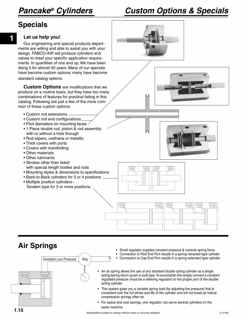
Custom Options & Specials
Specials
Let us help you!Our engineering and special products depart-
ments are willing and able to assist you with your design. FABCO-AIR will produce cylinders and valves to meet your specific application require-ments. In quantities of one and up. We have been doing it for almost 40 years. Many of our specials
standard catalog options.
Custom Options are modifications that we produce on a routine basis, but they have too many combinations of features for practical listing in this catalog. Following are just a few of the more com-mon of these custom options:
with or without a hole through
with special length bodies and rods
2-14-08
Constant Low Pressure Reg.
Air Springs
regulated pressure (must be a relieving regulator) to the proper port of the double acting cylinder.
consistent over the full stroke and life of the cylinder and will not break as helical compression springs often do.
same machine.
1
Specifications subject to change without notice or incurring obligation
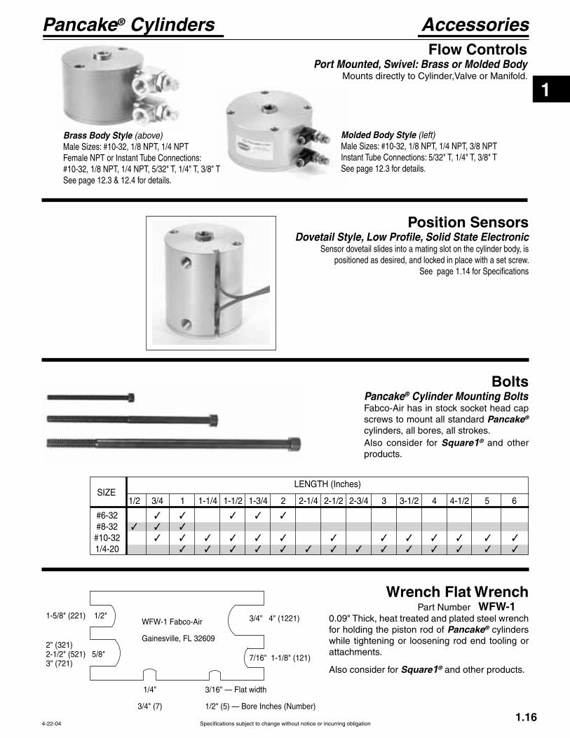
Pancake® Cylinders AccessoriesFlow Controls
Port Mounted, Swivel: Brass or Molded Body
Brass Body Style (above)
See page 12.3 & 12.4 for details.
Molded Body Style (left)
See page 12.3 for details.
Position SensorsDovetail Style, Low Profile, Solid State Electronic
Sensor dovetail slides into a mating slot on the cylinder body, is positioned as desired, and locked in place with a set screw.
See page 1.14 for Specifications
1.16
BoltsPancake® Cylinder Mounting Bolts Fabco-Air has in stock socket head cap screws to mount all standard Pancake® cylinders, all bores, all strokes.Also consider for Square1® and other products.
4-22-04
Wrench Flat Wrench Part Number WFW-1
for holding the piston rod of Pancake® cylinders while tightening or loosening rod end tooling or attachments.
Also consider for Square1® and other products.
1/2 3/4 1 1-1/4 1-1/2 1-3/4 2 2-1/4 2-1/2 2-3/4 3 3-1/2 4 4-1/2 5 6
1/4-20

1
Pancake® Cylinders
Specifications subject to change without notice or incurring obligation
Model Number1/2" (5) Bore
1.17 6-3-02
A complete library of cylinder CAD drawings is available from your local Fabco-Air Distributor or from the Fabco-Air web site – http://www.fabco-air.com
HOW TO ORDER1. Under Stroke – select letter(s) for desired Series and Stroke.
2. Under Bore – select 5 for 1/2" bore. Seven Other Bore Sizes are Available Bore Bore Code See page 3/4" --------------- 7 ----------------- 1.23 1 1/8" ------------121 --------------- 1.29 1 5/8" ------------221 --------------- 1.35 2" ---------------321 --------------- 1.41 2 1/2" ------------521 --------------- 1.47 3" ---------------721 --------------- 1.53 4" --------------1221 --------------- 1.59
3. Under Action – select letter(s) for desired action.
4. Under Prefix & Suffix Options– select letter(s) for desired options and add to model number.
EXAMPLES
E-5-X Original Series, 1/2" stroke - 1/2" Bore - Single Rod, Double Acting
TE-5-X-MR
ModelNumberCode
Bore Stroke Action
–TE –5 –X MRLeave blank ifnone desired
Metric MSee pages 1.7, 1.19 & 1.22
Bore Code 1/2" 5 12.7mm 5
Grey shading indicates sensors are not available.
Strokes are NOT affected by magnetic piston Option “E”
Standard Strokes
Original Series Action X O XDR ODR OP Stroke 1/16 A A A 1/8 B B B 1/4 C C C 3/8 D D D
5/8 F F – 3/4 G G – 1 H H – 1 1/4 I I – 1 1/2 J J – 2 K K –
4 M – –
“T” SeriesIncludes PTFE piston bearing
Action X O OP Stroke
Action Single rod Double acting -X Single acting, spring retracted -O
-OP Double rod Double acting -XDR Single acting, spring retracted -ODR
See pages 1.5 & 1.6 for Action Information. See pages 1.18 & 1.21 for Standard Specifications
See pages 1.7 – 1.15 for general option information and pages 1.19, 1.20 & 1.22 for option specifications of 1/2" bore models.
Suffix Options
Male rod thread: Single rod -MR Double rod, rod end -MR Double rod, cap end -MR1 Double rod, both ends -MR2
-VQuad seals -Q
-K
to 2" stroke only -NRHole thru double rod shaft : 1/16" hole -06
Finish: ProCoat™ -NStroke collar: 1/8" -C1 1/4" -C2 3/8" -C3 1/2" -C4 5/8" -C5 3/4" -C6 7/8" -C7Rubber Bumpers: Rod end -BF Cap end -BR Both ends -BFRAdjustable retract stroke (Over 1" adjustment add desired length, e.g. -RS2) -RSClevis mount: Ports in-line with slot -PM Ports 90° to slot -SM
-EPM Ports 90° to tang -ESM
-F Double rod, rod end -F Double rod, cap end -F1 Double rod, both ends -F2Magnetic piston & sensor mounting slot(s) -E Order sensors separately. See page 1.14 Stroke length determines number of mounting slots. See page 1.14, 1.20, 1.21.

1
Specifications subject to change without notice or incurring obligation
Pancake® Cylinders
1.18
Standard Specifications1/2" (5) BoreSingle Rod
ForSingle Rod, Double Acting, Nonrotating
See Option -K on page 1.20
Original Series "T" Series
Action –X Double Acting Action –X Double Acting
Note 1 Note 1 Note 1 Note 1 Note 1 Note 1
Stroke, Inch 1/16 1/8 1/4 3/8 1/2 5/8 3/4 1 1 1/4 1 1/2 2 3 4 1/8 1/4 3/8 1/2 5/8 1 1 1/4 1 1/2 2 3 4 Stroke, Letter
B1 .83 .83 .96 1.08 1.21 1.36 1.49 1.83 2.08 2.33 2.96 3.96 4.96 .96 1.08 1.21 1.36 1.49 1.83 2.08 2.33 2.96 3.96 4.96
K1 .56 .56 .69 .81 .94 1.09 1.22 .69 .81 .94 1.09 1.22 Y1 .46 .46 .46 .46 .46 .46 .46 .46 .46 .46 .55 .55 .55 .46 .46 .46 .46 .46 .46 .46 .46 .55 .55 .55
Weight, lb. .08 .08 .08 .09 .11 .12 .13 .16 .19 .21 .27 .36 .46 .08 .09 .11 .12 .13 .16 .19 .21 .27 .36 .46
B3 .83 .96 1.08 1.36 1.49 1.83 2.33 2.96 2.96 3.96 3.96 NA* NA* 1.08 1.36 1.49 1.83 2.33 2.96 2.96 3.96 3.96 NA* NA*
K3 .56 .69 .81 1.09 1.22 " " .81 1.09 1.22 " " Y3 .46 .46 .46 .46 .46 .46 .46 .55 .55 .55 .55 " " .46 .46 .46 .46 .46 .55 .55 .55 .55 " "
Weight,. lb. .08 .09 .10 .12 .13 .16 .22 .28 .28 .37 .37 " " .08 .09 .10 .12 .13 .16 .22 .28 .28 " " Preload, lb. 2.0 2.0 .9 1.2 .7 1.9 1.2 1.0 1.7 1.3 1.3 " " 2.8 2.0 1.2 1.9 1.9 1.0 1.7 1.3 1.3 " " End of Stroke, lb. 3.2 3.2 3.2 3.2 3.2 3.5 3.2 3.5 5.7 5.3 6.7 " " 3.2 3.2 3.2 3.5 3.5 3.5 5.7 5.3 5.3 " "
B4 .95 1.16 1.39 1.80 2.05 NA* NA* NA* NA* NA* NA* NA* NA* 1.26 1.67 1.92 NA* NA* NA* NA* NA* NA* NA* NA*
K4 .63 .77 .88 1.16 1.29 " " " " " " " " .88 1.16 1.29 " " " " " " " " Y4 .52 .58 .71 .83 .96 " " " " " " " " .58 .70 .83 " " " " " " " "
Weight, lb. .08 .09 .12 .13 .14 " " " " " " " " .08 .09 .12 " " " " " " " " Preload, lb. 1.7 1.7 .7 1.2 .7 " " " " " " " " 1.7 1.7 .7 " " " " " " " " End of Stroke, lb. 3.0 3.0 3.0 3.2 3.2 " " " " " " " " 3.0 3.0 3.0 " " " " " " " "
Note 1 Note 1 Note 1 Note 1 Note 1 Note 1
Action –OP Single Acting, Spring ExtendedAction –OP Single Acting, Spring Extended
Action –O Single Acting, Spring RetractedAction –O Single Acting, Spring Retracted
Note 1 Note 1 Note 1 Note 1 Note 1 Note 1Note 1 Note 1 Note 1 Note 1 Note 1 Note 1
4-22-04
Action –XDouble Acting
Note 1:Strokes H–M &
Holes on each end.
See page 1.16 forMounting Bolts.
Seal Kits for Series:
1.133/16 x .11
Wrench Flat
8-32 x E1Female Rod Thread.88 Bolt Circle.14 Dia. Thru.23 C'Bore x .14 Dp.for 2, #6SHCSH–M & TH–TM.See Note 1
.25 Rod Dia.
.13
B1 K1
Y1Z1
.13
Cap End Face10-32 Ports with .38 Dia. SpotfaceStrokes A–D & TC–TD are ported on Opposite Sides
90°Rod End Face
Action –OSingle ActingSpring Retracted
Note 1:
Holes on each end.See page 1.16 forMounting Bolts.
See chart for SpringForces: Preload and
Seal Kits for Series:
1.133/16 x .11
Wrench Flat
8-32 x E3Female Rod Thread.88 Bolt Circle.14 Dia. Thru.23 C'Bore x .14 Dp.for 2, #6SHCSF–K & TF–TK.See Note 1
.25 Rod Dia.
.13
B3 K3
Y3Z3
.13
Cap End Face10-32 Ports with .38 Dia. SpotfaceStrokes A–C & TC are ported on Opposite Sides
90°Rod End Face
Action –OPSingle ActingSpring Extended
See page 1.16 forMounting Bolts.
See Chart for SpringForces: Preload
Seal Kits for Series:
1.133/16 x .11
Wrench Flat
8-32 x E4Female Rod Thread
.88 Bolt Circle
.14 Dia. Thru
.23 C'Bore x .14 Dp.for 2, #6SHCS
.25 Rod Dia.
.13 + Stroke
B4 K4
Y4
Z4
.19
Cap End Face10-32 Ports with .38 Dia. SpotfaceStrokes A–C & TC are ported on Opposite Sides
90°Rod End Face

1
Pancake® Cylinders
Specifications subject to change without notice or incurring obligation1.19
.25
.41
Oil filled bushing
.44 + B
.34
.23
-EPMPort LocationIN LINE with Tang
-ESMPort Location90° to Tang
See Page 1.18
.251
.63
.25
.41
.63
Oil filled bushings
.44 + B
.34
.25 .83
-PMPort LocationIN LINE with Slot -SM
Port Location90° to Slot
See Page 1.18
Note 1
Note 1:Hole Diameter = .251Pin Diameter = .250Pin (416 Stainless Steel) and Clips are included
Option Specifications1/2" (5) BoreAlso See Page 1.18
Suffix Options -EPM & -ESM Eye Mount
with Actions: -X, -O, -OPAlso see Option Information on page 1.13.
Suffix Options -PM & -SM Clevis Mount
with Actions: -X, -O, -OPAlso see Option Information on page 1.13.
-X -O NA NA -OP NA NA
Suffix Optionsthe Actions indicated (Specifications on page 1.18. – Also see Option Information on pages 1.7 thru 1.15.
Prefix Option -M Metric Cylinder & Rod Thread, 12.7mm Bore
Also see Option Information on page 1.7. 22.2mm Bolt Circle
M5 Ports with 9.5mm Dia. Spotface
M4 x 12.7
Standard Female Rod Thread M4.Male Rod ThreadOption -MR shown.
Mounting Holes3.6mm Diameter Thru5.9mm C'Bore x 3.6mm Dp.2 Places for M3 SHCSExcept Strokes H-M &TH - TM which have two M4 x 12.0mm Dp.Tapped Mounting Holes on each end.
Thread PitchesM3 = 0.5mmM4 = 0.7mmM5 = 0.8mm
Conversion FactorInches x 25.4 = mm
Original Series Stroke mm 1.6 3.2 6.4 9.5 12.7 15.9 19.1 25.4 31.8 38.1 50.8 76.2 101.6
Stroke mm 3.2 6.4 9.5 12.7 15.9 25.4 31.8 38.1 50.8 76.2 101.6“T” Series
EM-02 Eye Bracket KitMates RC-16 Rod Clevis shown on the left.
EM-04 Eye Bracket Kit Mates with Clevis Mount above.Order separately.
RC-16 Rod Clevis and Pin
Female Rod thread in Pancake® Cylinders. Slot & Pin Mate with
shown on the right.
.19
Pin Diameter .1875
Optional Metric
m1.00
.75
.70 .38 .33
.50
Materials:
Stud – SteelPin – 416 Stainless SteelPin & Clips are included
PM-04 Clevis Bracket Kit
Order separately.
.63 .881.25
.56.81
Hole .251Pin .250Pin (416StainlessSteel) & Clipsincluded. Oil Filled Bushingsare Standard.
.41.30
.83.63
.27 Dia. 4 Placeson Square Patternfor Flat Head Screws.
sare included.
.25
.16 Material:
.31.41
.87
.16
1.25
1.25.88
Hole .251Oil filled bushingis standard
.23
.88 .56.27 Dia. 4 Placesfor Flat Head Screws
are included
Material:
.31.36
.87
.16
1.25
1.25.88
Hole .1885Oil filled bushingis standard
.18
.88 .56.27 Dia. 4 Placesfor Flat Head Screws
are included
Material:
4-1-08

1
Specifications subject to change without notice or incurring obligation
Pancake® Cylinders
#1#2
Sensors available for “D” & “TD” strokes and longer. Strokes D & TD are ported on opposite sides.
60° 60°
.09" Max
Wire outlet is in-line withsensor mounting slot
1.31.75
.751.50
1.13.56
.63
.38
.20 Dia..50 Dia.
.09
Option Specifications
1.20
.17
.042 Stroke AdjustmentPer Revolution
.06 + B
1/2 He
Adjusting Screw
.25 HeStainless Steel Piston Rod
8-32 x .50
.13
.38
.38 + B (for A – J Strok .29 + B (f es)
1.13
Pilot Dia. .495 .491
1/2-201/2-20
.72
5/8
.25
1.80.99
.751.50
1.13.56
.20 Dia.
.09
.25
.50 Dia.
Suffix Option -RS Adjustable Retract StrokeAvailable on Original and "T" Series with Actions -X, -O, -OP.Also see Option Information on page 1.11
Standard Adjustment is 1".
Suffix Option -NR Nonrotating, Single Acting
Available on Original and "T" Series with Action -O. Also see Option Information on page 1.8
Suffix Option -MR Male Rod Thread
Available on Original and "T" Series with Actions -X, -O, -OP. Also see Option Information on page 1.8
Suffix Option -F Threaded Nose MountAvailable on Original and "T" Series with Actions -X, -O, -OP.Also see Option Information on page 1.13
Accessory – Plated steel nose mounting bracketsMust be ordered separatelyAngled Part Number BRK-201 Flat Part Number BRK-202
90° Ref.
61°
A – J.48 + B
K – M.38 + B
.38
.25.56
.88 Standard Rod EndBrass Clamp
Ground Tool Steel Pinis Guided by Precision Hole in End Cap
Clearance in Bodyfor Guide Pin
.13
.50
Suffix Option -K Nonrotating, Double ActingAvailable on Original and "T" Series with Action -X, -O, -OP.
-OP only use B4 as shown on page 1.18. No additional length is required
1/2" (5) BoreAlso See Page 1.18
4-1-08
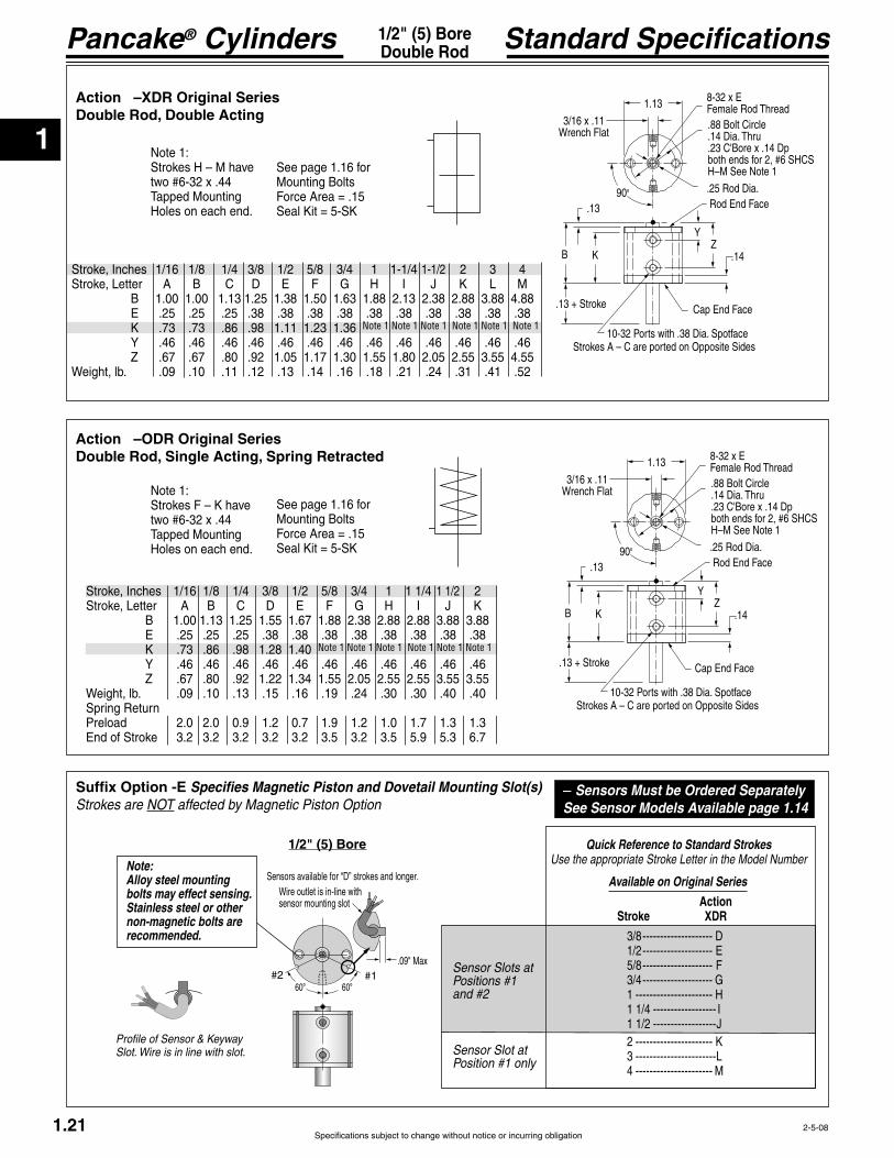
Suffix Option -E Specifies Magnetic Piston and Dovetail Mounting Slot(s)Strokes are NOT affected by Magnetic Piston Option
Quick Reference to Standard StrokesUse the appropriate Stroke Letter in the Model Number
1/2" (5) Bore
– Sensors Must be Ordered SeparatelySee Sensor Models Available page 1.14
Note: Alloy steel mounting bolts may effect sensing. Stainless steel or other nonmagnetic bolts are recommended.
Sensor Slots at Positions #1 and #2
Sensor Slot atPosition #1 only
Available on Original Series
Action Stroke X
3/8 -------------------- D 1/2 -------------------- 5/8 -------------------- F 3/4 -------------------- G 1 ---------------------- H 1 1/4 ------------------ I 1 1/2 ------------------J 2 ---------------------- K 3 ----------------------- 4 ---------------------- M
Available on “T”Series
Action Stroke X
1/4 ------------- 3/8 ------------- 1/2 ------------- 5/8 ------------- 1 --------------- 1 1/4 ----------- 1 1/2 ---------- 2 --------------- 3 --------------- 4 ---------------Profile of Sensor & Keyway
Slot. Wire is in line with slot.
Nut Part No.MC-500-195 isincluded.Material: Brass
Rotational Tolerance with Piston Rod Fully Retracted (Clamp near Body) is ±1°. Cylinder is not intended to carry any rotational load.
1
Pancake® Cylinders
Specifications subject to change without notice or incurring obligation
#1#2
Sensors available for “D” strokes and longer.
60° 60°
.09" Max
Wire outlet is in-line withsensor mounting slot
Stroke, Inches 1/16 1/8 1/4 3/8 1/2 5/8 3/4 1 1-1/4 1-1/2 2 3 4
B 1.00 1.00 1.13 1.25 1.38 1.50 1.63 1.88 2.13 2.38 2.88 3.88 4.88
K .73 .73 .86 .98 1.11 1.23 1.36 Y .46 .46 .46 .46 .46 .46 .46 .46 .46 .46 .46 .46 .46
Weight, lb. .09 .10 .11 .12 .13 .14 .16 .18 .21 .24 .31 .41 .52
1.21
1/2" (5) BoreDouble Rod Standard Specifications
Suffix Option -E Specifies Magnetic Piston and Dovetail Mounting Slot(s)Strokes are NOT affected by Magnetic Piston Option
Available on Original Series
Action Stroke XDR
3/8 -------------------- D 1/2 -------------------- 5/8 -------------------- F 3/4 -------------------- G 1 ---------------------- H 1 1/4 ------------------ I 1 1/2 ------------------J 2 ---------------------- K 3 ----------------------- 4 ---------------------- M
Quick Reference to Standard StrokesUse the appropriate Stroke Letter in the Model Number
1/2" (5) Bore
– Sensors Must be Ordered SeparatelySee Sensor Models Available page 1.14
Action –XDR Original SeriesDouble Rod, Double Acting
Action –ODR Original SeriesDouble Rod, Single Acting, Spring Retracted
Note 1 Note 1 Note 1 Note 1 Note 1 Note 1
Note 1:Strokes H – M have
Holes on each end.
Note 1:Strokes F – K have
Holes on each end.
See page 1.16 forMounting Bolts
See page 1.16 forMounting Bolts
1.13
3/16 x .11Wrench Flat
8-32 x EFemale Rod Thread.88 Bolt Circle.14 Dia. Thru.23 C'Bore x .14 Dpboth ends for 2, #6 SHCSH–M See Note 1
.25 Rod Dia.
.13
B K
YZ
.14
Cap End Face
10-32 Ports with .38 Dia. Spotface
90°Rod End Face
Strokes A – C are ported on Opposite Sides
.13 + Stroke
1.13
3/16 x .11Wrench Flat
8-32 x EFemale Rod Thread.88 Bolt Circle.14 Dia. Thru.23 C'Bore x .14 Dpboth ends for 2, #6 SHCSH–M See Note 1
.25 Rod Dia.
.13
B K
YZ
.14
Cap End Face
10-32 Ports with .38 Dia. Spotface
90°Rod End Face
Strokes A – C are ported on Opposite Sides
.13 + Stroke
2-5-08
Stroke, Inches 1/16 1/8 1/4 3/8 1/2 5/8 3/4 1 1 1/4 1 1/2 2
B 1.00 1.13 1.25 1.55 1.67 1.88 2.38 2.88 2.88 3.88 3.88
K .73 .86 .98 1.28 1.40 Y .46 .46 .46 .46 .46 .46 .46 .46 .46 .46 .46
Weight, lb. .09 .10 .13 .15 .16 .19 .24 .30 .30 .40 .40Spring Return Forces, lb.Preload 2.0 2.0 0.9 1.2 0.7 1.9 1.2 1.0 1.7 1.3 1.3
Note 1 Note 1 Note 1 Note 1 Note 1 Note 1
Sensor Slots atPositions #1 and #2
Sensor Slot atPosition #1 only
Note: Alloy steel mounting bolts may effect sensing. Stainless steel or other non-magnetic bolts are recommended.
Profile of Sensor & Keyway Slot. Wire is in line with slot.
1
Specifications subject to change without notice or incurring obligation
Pancake® Cylinders
1.22
Option Specifications1/2" (5) BoreAlso See Page 1.21
Suffix Option -F, -F1, -F2 Threaded Nose Mount (See info page 1.13)Available on Original Series with Actions -XDR, -ODR.For Rod End only use -FFor Cap End only use -F1For Both Ends use -F2
1.31.75
.751.50
1.13.56
.63
.38
.20 Dia..50 Dia.
.09
Part No: BRK-201
5/8
.25.72
1/2-20
Nut. Part No. MC-500-195is included.Material: Brass
Accessory Nose Mounting BracketsOrder separately – Material Plated Steel
.13 .38 .13 +Stroke
.38+ B
1.13
1/2-20Pilot Dia. .495
.491
Suffix Option -K Nonrotating, Double ActingAvailable on Original Series with Actions: -XDR, -ODR.
Rotational Tolerance with Piston Rod Fully Retracted (Clamp near Body) is ±1°.
Cylinder is not intended to carry any rota-tional load.
90° Ref.
61°
A – J.48 + B
K – M.38 + B
.38
.25.56
.88 Standard Rod EndBrass Clamp
Ground Tool Steel Pinis Guided by Precision Hole in End Cap
Clearance in Bodyfor Guide Pin
.13
.50
.13 + Stroke
-XDR -ODR NA NA
Suffix Options charted on the right are available on Original Series with the Actions indicated (Specifications on page 1.21. – Also see Option Information on pages 1.7 thru 1.15.
Suffix Option -NR Nonrotating, Single ActingAvailable on Original Series with Action -ODRAlso see Option Information on page 1.8.
.25 HeStainless Steel Piston Rod
Suffix Option -MR, -MR1, -MR2Male Rod ThreadAvailable on Original Series with Actions -XDR, -ODR.
Also see Option Information on Page 1.8
8-32 x .50
Prefix Option -M Metric Cylinder & Rod Thread, 12.7mm BoreAvailable on Original Series with Actions: -XDR, -ODRAlso see Option Information on page 1.7.
22.2mm Bolt Circle
M5 Ports with 9.5mm Dia. Spotface
M4 x 12.7
Standard Female Rod Thread M4.Male Rod ThreadOption -MR shown.
Mounting Holes3.6mm Diameter Thru5.9mm C'Bore x 3.6mm Dp.2 Places for M3 SHCSExcept Strokes H-M which have two M4 x 12.0mm Dp.Tapped Mounting Holes on each end.
Thread PitchesM3 = 0.5mmM4 = 0.7mmM5 = 0.8mm
Conversion FactorInches x 25.4 = mm
Stroke mm 1.6 3.2 6.4 9.5 12.7 15.9 19.1 25.4 31.8 38.1 50.8 76.2 101.6
1.80.99
.751.50
1.13.56
.20 Dia.
.09
.25
.50 Dia.
Part No: BRK-202
4-22-04

1
Pancake® Cylinders
Specifications subject to change without notice or incurring obligation
HOW TO ORDER1. Under Stroke – select letter(s) for desired Series and Stroke.
2. Under Bore – select 7 for 3/4" bore. Seven Other Bore Sizes are Available Bore Bore Code See page 1/2" --------------- 5 ----------------- 1.17 1 1/8" ------------121 --------------- 1.29 1 5/8" ------------221 --------------- 1.35 2" ---------------321 --------------- 1.41 2 1/2" ------------521 --------------- 1.47 3" ---------------721 --------------- 1.53 4" --------------1221 --------------- 1.59
3. Under Action – select letter(s) for desired action.
4. Under Prefix & Suffix Options– select letter(s) for desired options and add to model number.
EXAMPLES
E-7-X Original Series, 1/2" stroke - 3/4" Bore - Single Rod, Double Acting
TE-7-X-MR
1.23
A complete library of cylinder CAD drawings is available from your local Fabco-Air Distributor or from the Fabco-Air web site – http://www.fabco-air.com
6-3-02
Model Number3/4" (7) Bore
ModelNumberCode
Bore Stroke Action
–TE –7 –X MRLeave blank if none desired
Metric MSee pages 1.7, 1.25, 1.28
Bore Code 3/4" 7 19.1mm 7
Action Single rod Double acting -X Double acting, Nonrotating -XK Single acting, spring retracted -O
-OP Double rod Double acting -XDR Double acting, Nonrotating -XDRK Single acting, spring retracted -ODR
See pages 1.5 & 1.6 for Action Information. See pages 1.24 & 1.27 for Standard Specifications
See pages 1.7 – 1.15 for general option information and pages 1.25, 1.26 & 1.28 for option specifications of 3/4" bore models.
Grey shading indicates sensors are not available.
Strokes are NOT af-fected by magnetic piston Option “E”
Standard StrokesNote 1: For action XK strokes A – G are decreased by 1/8" from those shown (Original Series only).
Note 2: For action XDRK strokes A – M are decreased by 1/8" from those shown (Original Series only).
Original Series
Action X XK1 O XDR XDRK2 ODR OP Stroke 1/16 A A A 1/8 B B B 1/4 C C C 3/8 D D D
5/8 F F – 3/4 G G – 1 H H – 1 1/4 I I – 1 1/2 J J – 2 K K –
4 M – –
“T” SeriesIncludes PTFE piston bearing
Action X, XK O OP Stroke
Suffix Options
Male rod thread: Single rod -MR Double rod, rod end -MR Double rod, cap end -MR1 Double rod, both ends -MR2
-V
Quad seals -Q
for load guiding (See page 1.65) -G
to 2" stroke only -NR
Hole thru double rod shaft : 1/16" hole -06
Finish: ProCoat™ -N
Stroke collar: 1/8" -C1 1/4" -C2 3/8" -C3 1/2" -C4 5/8" -C5 3/4" -C6 7/8" -C7
Rubber Bumpers: Rod end -BF Cap end -BR Both ends -BFR
Adjustable retract stroke (Over 1" adjustment add desired length, e.g. -RS2) -RS
Clevis mount: Ports in-line with slot -PM Ports 90° to slot -SM
-EPM Ports 90° to tang -ESM
-F Double rod, rod end -F Double rod, cap end -F1 Double rod, both ends -F2
Magnetic piston & sensor mounting slot(s) -E Order sensors separately. See page 1.14. Stroke length determines number of mounting slots. See page 1.14, 1.26, or 1.28.
1
Specifications subject to change without notice or incurring obligation
Pancake® Cylinders 3/4" (7) BoreSingle Rod
1.24
Standard Specifications
4-23-04
Action –XK Double Acting, Nonrotating
Action –O Single Acting, Spring Retracted
Action –OP Single Acting, Spring Extended
Original Series "T" Series
Action –O Single Acting, Spring Retracted
Action –X Double Acting Action –X Double Acting
Use Strokes & Dimensions under
Action –OP Single Acting, Spring Extended
Action –XK Double Acting, Nonrotating
Note 1 Note 1 Note 1 Note 1 Note 1 Note 1
Note 1 Note 1 Note 1 Note 1 Note1 Note 1 Note 1 Note 1 Note 1 Note 1 Note 1 Note 1
Note 1 Note 1 Note 1 Note 1 Note 1 Note 1 Note 1 Note 1 Note 1 Note 1 Note 1 Note 1
Action –XKDouble ActingNonrotating
Note 1:Strokes H–M &
Holes on each end.
See page 1.16 forMounting Bolts.
Seal Kits for Series:
1.501/4 x .11
Wrench FlatRandom Rotation
10-32 x E1Female Rod Thread1.19 Bolt Circle.14 Dia. Thru.23 C'Bore x .14 Dp.for 2, #6SHCSH–M & TH–TM.See Note 1.31 Rod Dia.
.13
B2 K2
Y2Z2
.13
Cap End Face10-32 Ports with .38 Dia. Spotface
90°Rod End Face
Rod RotationTolerance 1°
Strokes C–D & TC–TD are ported on Opposite Sides
Action –OPSingle ActingSpring Extended
See page 1.16 forMounting Bolts.
See Chart for SpringForces: Preload
Seal Kits for Series:
1.501/4 x .11
Wrench Flat
10-32 x E4Female Rod Thread
1.19 Bolt Circle.14 Dia. Thru.23 C'Bore x .14 Dp.for 2, #6SHCS .31 Rod Dia.
.13 + Stroke
B4 K4
Y4
Z4
.19
Cap End Face10-32 Ports with .38 Dia. SpotfaceStrokes A–C & TC are ported on Opposite Sides
90°Rod End Face
Action –OSingle ActingSpring Retracted
Note 1:
Holes on each end.See page 1.16 forMounting Bolts.
See chart for SpringForces: Preload and
Seal Kits for Series:
1.50
1/4 x .11Wrench Flat
10-32 x E3Female Rod Thread1.19 Bolt Circle.14 Dia. Thru.23 C'Bore x .14 Dp.for 2, #6SHCSF–K & TF–TKSee Note 1
.31 Rod Dia.
.13
B3 K3
Y3Z3
.13
Cap End Face10-32 Ports with .38 Dia. Spotface
90°Rod End Face
Strokes A–C & TC are ported on Opposite Sides
Action –XDouble Acting
Note 1:Strokes H–M &
Holes on each end.
See page 1.16 forMounting Bolts.
Seal Kits for Series:
1.50
1/4 x .11Wrench Flat
10-32 x E1Female Rod Thread1.19 Bolt Circle.14 Dia. Thru.23 C'Bore x .14 Dp.for 2, #6SHCSH–M & TH–TM.See Note 1.31 Rod Dia.
.13
B1 K1
Y1Z1
.13
Cap End Face10-32 Ports with .38 Dia. Spotface
90°Rod End Face
Strokes A–D & TC–TD are ported on Opposite Sides
Stroke, Inch 1/16 1/8 1/4 3/8 1/2 5/8 3/4 1 1 1/4 1 1/2 2 3 4 1/8 1/4 3/8 1/2 5/8 1 1 1/4 1 1/2 2 3 4 Stroke, Letter
B1 .83 .83 .96 1.08 1.21 1.36 1.49 1.83 2.08 2.33 2.96 3.96 4.96 .96 1.08 1.21 1.36 1.49 1.83 2.08 2.33 2.96 3.96 4.96
K1 .56 .56 .69 .81 .94 1.09 1.22 .69 .81 .94 1.09 1.22 Y1 .46 .46 .46 .46 .46 .46 .46 .46 .46 .46 .55 .55 .55 .46 .46 .46 .46 .46 .46 .46 .46 .55 .55 .55
Weight, lb. .14 .14 .15 .17 .20 .21 .23 .28 .32 .36 .46 .63 .78 .15 .17 .20 .21 .23 .28 .32 .36 .46 .63 .78
Stroke, Inch 1/8 1/4 3/8 1/2 5/8 1 1 1/4 1 1/2 2 3 4 B2 .96 1.08 1.21 1.36 1.49 1.83 2.08 2.33 2.96 3.96 4.96 Stroke, Letter K2 .69 .81 .94 1.09 1.22 Y2 .46 .46 .46 .46 .46 .46 .46 .46 .55 .55 .55 Weight, lb. .15 .18 .21 .22 .24 .29 .33 .37 .48 .65 .81
B3 .83 .96 1.08 1.36 1.49 1.83 2.33 2.96 2.96 3.96 3.96 NA* NA* 1.08 1.36 1.49 1.83 2.33 2.96 2.96 3.96 3.96 NA* NA*
K3 .56 .69 .81 1.09 1.22 " " .81 1.09 1.22 " " Y3 .46 .46 .46 .46 .46 .46 .55 .55 .55 .55 .55 " " .46 .46 .46 .46 .46 .55 .55 .55 .55 " "
Weight,. lb. .14 .16 .18 .22 .23 .28 .36 .46 .46 .63 .63 " " .18 .22 .23 .28 .28 .46 .46 .63 .63 " " Preload, lb. 2.0 2.7 1.5 2.5 2.0 2.5 2.5 2.2 1.5 1.3 1.3 " " 2.8 1.5 2.5 2.5 2.5 1.5 1.2 1.3 1.3 " " End of Stroke, lb. 3.0 4.5 4.5 4.7 4.7 4.8 4.8 4.9 5.0 5.3 6.7 " " 4.5 4.5 4.8 4.8 4.8 4.9 5.0 5.3 6.7 " "
B4 .95 1.16 1.39 1.80 2.05 NA* NA* NA* NA* NA* NA* NA* NA* 1.26 1.67 1.92 NA* NA* NA* NA* NA* NA* NA* NA*
K4 .63 .77 .88 1.16 1.29 " " " " " " " " .88 1.16 1.29 " " " " " " " " Y4 .52 .58 .71 .83 .96 " " " " " " " " .58 .70 .83 " " " " " " " "
Weight, lb. .14 .16 .18 .22 .24 " " " " " " " " .18 .22 .24 " " " " " " " " Preload, lb. 2.0 2.7 1.5 2.5 2.0 " " " " " " " " 1.5 2.5 2.0 " " " " " " " " End of Stroke, lb. 3.0 4.5 4.5 4.7 4.7 " " " " " " " " 4.5 4.8 4.8 " " " " " " " "

1
Pancake® Cylinders
Specifications subject to change without notice or incurring obligation1.25
.25
.41
Oil filled bushing
.44 + B
.34
.23
-EPMPort LocationIN LINE with Tang
-ESMPort Location90° to Tang
See Page 1.24
.251
.63
.25
.41
.63
Oil filled bushings
.44 + B
.34
.25 .83
-PMPort LocationIN LINE with Slot -SM
Port Location90° to Slot
See Page 1.24
Note 1
Note 1:Hole Diameter = .251Pin Diameter = .250Pin (416 Stainless Steel) and Clips are included
Option Specifications3/4" (7) BoreAlso See Page 1.24
6-6-05
Suffix Optionsthe Actions indicated (Specifications on page 1.24. – Also see Option Information on pages 1.7 thru 1.15.
-X -XK -O NA NA -OP NA NA
Suffix Options -EPM & -ESM Eye Mount
with Actions: -X, -XK, -O, -OPAlso see Option Information on page 1.13.
Suffix Options -PM & -SM Clevis Mount
with Actions: -X, -XK, -O, -OPAlso see Option Information on page 1.13.
Prefix Option -M Metric Cylinder & Rod Thread, 19.1mm Bore
Also see Option Information on page 1.7.30.2mmBolt Circle
M5 Ports with 9.5mm Dia.Spotface
M5 x 12.7
Standard Female Rod Thread M5.Male Rod ThreadOption -MR shown.
Mounting Holes4.3mm Diameter Thru7.2mm C'Bore x 3.6mm Dp.2 Places for M4 SHCSExcept Strokes H-M and TH-TM which have two M5 x 11.1 Dp.Tapped Mounting Holes on each end.
Thread PitchesM4 = 0.7mmM5 = 0.8mm
Conversion FactorInches x 25.4 = mm
Original Series Stroke mm 1.6 3.2 6.4 9.5 12.7 15.9 19.1 25.4 31.8 38.1 50.8 76.2 101.6
Stroke mm 3.2 6.4 9.5 12.7 15.9 25.4 31.8 38.1 50.8 76.2 101.6
“T” Series
EM-02 Eye Bracket KitMates RC-19 Rod Clevis shown on the left.
EM-04 Eye Bracket Kit Mates with Clevis Mount above.Order separately.
RC-19 Rod Clevis and Pin
Female Rod thread in Pancake® Cylinders. Slot & Pin Mate with
shown on the right.
.19
Pin Diameter .1875
Optional Metric
m1.00
.75
.70 .38 .33
.50
Materials:
Stud – SteelPin – 416 Stainless SteelPin & Clips are included
PM-04 Clevis Bracket Kit
Order separately.
.63 .881.25
.56.81
Hole .251Pin .250Pin (416StainlessSteel) & Clipsincluded. Oil Filled Bushingsare Standard.
.41.30
.83.63
.27 Dia. 4 Placeson Square Patternfor Flat Head Screws.
sare included.
.25
.16 Material:
.31.41
.87
.16
1.25
1.25.88
Hole .251Oil filled bushingis standard
.23
.88 .56.27 Dia. 4 Placesfor Flat Head Screws
are included
Material:
.31.36
.87
.16
1.25
1.25.88
Hole .1885Oil filled bushingis standard
.18
.88 .56.27 Dia. 4 Placesfor Flat Head Screws
are included
Material:
1
Specifications subject to change without notice or incurring obligation
Pancake® Cylinders
Sensor Slotsat Positions #1 and #2
Sensor Slot atPosition #1 only
65° 65°
Sensors available for “D” & “TD” strokes and longer. Strokes D & TD are ported on opposite sides.
#1#2.14" Ref. to 60 wire outlet;Zero stick-out of sensor body
1.26
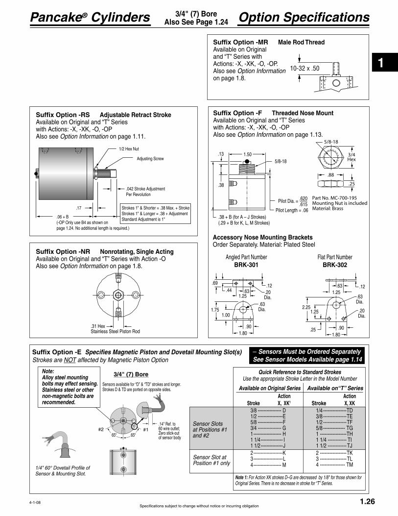
Option Specifications3/4" (7) BoreAlso See Page 1.24
Accessory Nose Mounting BracketsOrder Separately. Material: Plated Steel
4-1-08
Suffix Option -E Specifies Magnetic Piston and Dovetail Mounting Slot(s)Strokes are NOT affected by Magnetic Piston Option
Quick Reference to Standard StrokesUse the appropriate Stroke Letter in the Model Number
Available on Original Series Action Stroke X, XK1
3/8 ---------------- D 1/2 ----------------- 5/8 -----------------F 3/4 ---------------- G 1 ------------------- H 1 1/4 --------------- I 1 1/2 ---------------J 2 --------------------K 3 -------------------- 4 ------------------- M
Available on“T” Series Action Stroke X, XK 1/4 --------------- 3/8 --------------- 1/2 --------------- 5/8 -------------- 1 ----------------- 1 1/4 ------------ 1 1/2 ------------ 2 ----------------- 3 ----------------- 4 ----------------
Note 1: For Action XK strokes D–G are decreased by 1/8" for those shown for Original Series. There is no decrease in stroke for “T” Series.
1/4" 60° Dovetail Profile of Sensor & Mounting Slot.
3/4" (7) Bore
– Sensors Must be Ordered SeparatelySee Sensor Models Available page 1.14
Note: Alloy steel mounting bolts may effect sensing. Stainless steel or other non-magnetic bolts are recommended.
.13
.38
.38 + B (for A – J Strokes) (.29 + B f es)
1.50
Pilot Dia. .620 .615
5/8-18
Suffix Option -RS Adjustable Retract Stroke
with Actions: -X, -XK, -O, -OPAlso see Option Information on page 1.11.
Suffix Option -MR Male Rod ThreadAvailable on Original
Actions: -X, -XK, -O, -OP.Also see Option Information on page 1.8.
5/8-18
.88
.25
3/4Hex
Part No. MC-700-195Mounting Nut is includedMaterial: Brass
Suffix Option -F Threaded Nose Mount
with Actions: -X, -XK, -O, -OPAlso see Option Information on page 1.13.
Angled Part NumberBRK-301
Flat Part NumberBRK-302
.17
.06 + B(-OP Only use B4 as shown on page 1.24. No additional length is required.)
.042 Stroke AdjustmentPer Revolution
Adjusting Screw
Standard Adjustment is 1"
Suffix Option -NR Nonrotating, Single Acting
Also see Option Information on page 1.8.
.31 HeStainless Steel Piston Rod
10-32 x .50
1.25
.63
.20Dia.
.12
.63Dia.
.901.80
2.25
.25
1.25
.69.44
1.25.63 .20
Dia.
.12
.63Dia.
.901.80
1.001.75

1
Pancake® Cylinders
Specifications subject to change without notice or incurring obligation
Stroke, Inches 1/16 1/8 1/4 3/8 1/2 5/8 3/4 1 1-1/4 1-1/2 2 3 4
B 1.00 1.00 1.13 1.25 1.38 1.50 1.63 1.88 2.13 2.38 2.88 3.88 4.88
K .73 .73 .86 .98 1.11 1.23 1.36 Y .46 .46 .46 .46 .46 .46 .46 .46 .46 .46 .46 .46 .46
Weight, lb. .16 .16 .19 .22 .23 .26 .28 .32 .36 .41 .49 .69 .86
Note 1 Note 1 Note 1 Note 1 Note 1 Note 1
Stroke, Inches 1/8 1/4 3/8 1/2 5/8 7/8 1 1/8 1 3/8 1 7/8 2 7/8 3 7/8
B 1.13 1.25 1.38 1.50 1.63 1.88 2.13 2.38 2.88 3.88 4.88
K .86 .98 1.11 1.23 1.36 Y .46 .46 .46 .46 .46 .46 .46 .46 .46 .46 .46
Weight, lb. .20 .22 .24 .27 .29 .33 .37 .43 .51 .71 .89
Note 1 Note 1 Note 1 Note 1 Note 1 Note 1
Note 1 Note 1 Note 1 Note 1 Note 1 Note 1
1.27
3/4" (7) BoreDouble Rod Standard Specifications
4-22-04
Action –XDR Original SeriesDouble Rod, Double Acting
Action –XDRK Original SeriesDouble Rod, Double Acting, Nonrotating
Action –ODR Original SeriesDouble Rod, Single Acting, Spring Retracted
Note 1:Strokes H – M have
Holes on each end.
Note 1:Strokes H – M have
Holes on each end.
Note 1:Strokes F – K have
Holes on each end.
See page 1.16 forMounting Bolts
See page 1.16 forMounting Bolts
See page 1.16 forMounting Bolts
1.50
1/4 x .11Wrench Flat
10-32 x EFemale Rod Thread1.19 Bolt Circle.14 Dia. Thru.23 C'Bore x .14 Dpboth endsfor 2, #6 SHCSH–M See Note 1.31 Rod Dia.
.13
B K
YZ
.14
Cap End Face
10-32 Ports with .38 Dia. Spotface
90°Rod End Face
Strokes A – C are ported on Opposite Sides
.13 + Stroke
1.501/4 x .11Wrench FlatRandomRotation
10-32 x EFemale Rod Thread1.19 Bolt Circle.14 Dia. Thru.23 C'Bore x .14 Dpboth endsfor 2, #6 SHCSH – M See Note 1.31 Rod Dia.
.13
B K
YZ
.14
Cap End Face
10-32 Port with .38 Dia. Spotface
90°
Rod End Face
Stroke C is ported on Opposite Sides
.13 + Stroke
RodRotationTolerance 1°
1.501/4 x .11
Wrench Flat
10-32 x EFemale Rod Thread
1.19 Bolt Circle.14 Dia. Thru.23 C'Bore x .14 Dpboth endsfor 2, #6 SHCSH–M See Note 1
.31 Rod Dia.
.13
B K
YZ
.14
Cap End Face
10-32 Port with .38 Dia. Spotface
90°Rod End Face
Strokes A – C are ported on Opposite Sides
.13 + Stroke
Stroke, Inches 1/16 1/8 1/4 3/8 1/2 5.8 3/4 1 1 1/4 1 1/2 2
B 1.00 1.13 1.25 1.55 1.67 1.88 2.38 2.88 2.88 3.88 3.88
K .73 .86 .98 1.28 1.40 Y .46 .46 .46 .46 .46 .46 .46 .46 .46 .46 .46
Weight, lb. .16 .19 .20 .22 .23 .33 .43 .51 .51 .71 .71Spring Return Forces, lb.Preload 2.0 2.8 1.5 2.5 2.0 2.5 2.5 2.2 1.5 1.3 1.3
1
Specifications subject to change without notice or incurring obligation
Pancake® Cylinders
Sensor Slots atPositions #1 and # 2
Sensor Slot atPosition #1 only
65° 65°
Sensors available for “D” strokes and longer.
#1#2.14" Ref. to 60 wire outlet;Zero stick-out of sensor body
1.28
Option Specifications3/4" (7) BoreAlso See Page 1.24
4-1-08
-XDR -XDRK -ODR NA NA
Suffix Options charted on the right are available on Original Series with the Actions indicated (Specifications on page 1.27. – Also see Option Information on pages 1.7 thru 1.15.
Suffix Option -E Specifies Magnetic Piston and Dovetail Mounting Slot(s)Strokes are NOT affected by Magnetic Piston Option
Quick Reference to Standard StrokesUse the appropriate Stroke Letter in the Model Number
3/4" (7) Bore
Note 2: For Action XDRK strokes D–M are decreased by 1/8" for those shown for Original Series.
Available on Original Series Action Stroke XDR, XDRK2
3/8 ---------------- D 1/2 ----------------- 5/8 -----------------F 3/4 ---------------- G 1 ------------------- H 1 1/4 --------------- I 1 1/2 ---------------J 2 --------------------K 3 -------------------- 4 ------------------- M
– Sensors Must be Ordered SeparatelySee Sensor Models Available page 1.14
Suffix Option -F, -F1, -F2 Threaded Nose MountAvailable on Original Serieswith Actions -XDR, -XDRK, -ODR.
-F-F1-F2
Also see Option Information on page 1.13
.13.38
.13 +Stroke
.38+ B
1.50
5/8-18Pilot Dia. .620
.615
5/8-18
.88
.25
3/4Hex
.69.44
1.25.63 .20
Dia.
.12
.63Dia.
.901.80
1.001.75 1.25
.63
.20Dia.
.12
.63Dia.
.901.80
2.25
.25
1.25
Accessory Nose Mounting BracketsOrder Separately. Material Plated Steel
BRK-301 BRK-302
Prefix Option -M Metric Cylinder & Rod Thread, 19.1mm BoreAvailable on Original Series with Actions: -XDR, -XDRK, -ODRAlso see Option Information on page 1.7. 30.2mm
Bolt Circle
M5 Ports with 9.5mm Dia.Spotface
M5 x 12.7
Standard Female Rod Thread M5.Male Rod ThreadOption -MR shown
Mounting Holes4.3mm Diameter Thru7.2mm C'Bore x 3.6mm Dp.2 Places for M4 SHCSExcept Strokes H-M and TH-TM which have two M5 x 11.1 Dp.Tapped Mounting Holes on each end.
Thread PitchesM4 = 0.7mmM5 = 0.8mm
Conversion FactorInches x 25.4 = mm
Stroke mm 1.6 3.2 6.4 9.5 12.7 15.9 19.1 25.4 31.8 3.81 50.8 76.2 101.6
Stroke mm NA NA 3.2 6.3 9.5 12.7 15.9 22.2 28.6 34.9 47.6 73.0 98.4
Action -XDR & -ODR -XDR
10-32 x .50
.31 HeStainless Steel Piston Rod
Suffix Option -MR, -MR1, -MR2 Male Rod ThreadAvailable on Original Series with Actions -XDR, -XDRK, -ODR.
–MR–MR1–MR2
Also see Option Information on Page 1.8
Suffix Option -NRNonrotating, Single ActingAvailable on Original Series with Actions: -ODRAlso see Option Information on page 1.8.
Action -XDRK
Note: Alloy steel mounting bolts may effect sensing. Stainless steel or other non-magnetic bolts are recommended.
1/4" 60° Dovetail Profile of Sensor & Mounting Slot.
Nut Part No. MC-700-195 isincluded. Material: Brass

1
Pancake® Cylinders
Specifications subject to change without notice or incurring obligation
ModelNumberCode
Bore Stroke Action
–D –121 –X MRLeave blank if none desired
Metric MSee pages 1.7, 1.31 & 1.34
Bore Code 1 1/8" 121 28.5mm 121
HOW TO ORDER
1. Under Stroke – select letter(s) for desired Series and Stroke.
2. Under Bore – select 121 for 1 1/8" bore. Seven Other Bore Sizes are Available Bore Bore Code See page 1/2" --------------- 5 ----------------- 1.17 3/4" --------------- 7 ----------------- 1.23 1 5/8" ------------221 --------------- 1.35 2" ---------------321 --------------- 1.41 2 1/2" ------------521 --------------- 1.47 3" ---------------721 --------------- 1.53 4" --------------1221 --------------- 1.59
3. Under Action – select letter(s) for desired action.
4. Under Prefix & Suffix Options– select letter(s) for desired options and add to model number.
EXAMPLESD-121-X Original Series, 1/2" stroke - 1 1/8" Bore - Single Rod, Double ActingTD-121-X-MR
Model Number1 1/8" (121) Bore
1.29
A complete library of cylinder CAD drawings is available from your local Fabco-Air Distributor or from the Fabco-Air web site – http://www.fabco-air.com
Action Single rod Double acting -X Double acting, Nonrotating -XK Single acting, spring retracted -O
-OP Double rod Double acting -XDR Double acting, Nonrotating
XDRK Single acting, spring retracted -ODR
See pages 1.5 & 1.6 for Action Information. See pages 1.30 & 1.33 for Standard Specifications
Grey shading indicates sensors are not available.
Strokes are NOT af-fected by magnetic piston Option “E”
Standard StrokesOriginal Series
Action X XK O XDR XDRK ODR OP Stroke 1/8 A A A 3/16 B B B 1/4 C C C 1/2 D* D D 3/4 X X X
1 1/4 F F F 1 1/2 G G G 1 3/4 H H – 2 I I – 3 J – – 4 K – –
“T” SeriesIncludes PTFE piston bearing
X Action XK O OP Stroke
* Note – Sensors not available:D-121-XK, TD-121-XK, D-121-XDRK
6-22-02
Suffix Options
Male rod thread: Single rod -MR Double rod, rod end -MR Double rod, cap end -MR1 Double rod, both ends -MR2
-T-V
Quad seals -Q
for load guiding (See page 1.65) -GHydraulic: Standard cover -HHole thru double rod shaft: 1/8" hole -13
-16
Finish: ProCoat™ -NStroke collar: 1/8" -C1 1/4" -C2 3/8" -C3 1/2" -C4 5/8" -C5 3/4" -C6 7/8" -C7Sound limiters: Rod end -LF Cap end -LR Both ends -LFRRubber Bumpers: Rod end -BF Cap end -BR Both ends -BFR
(Full stroke adjustment is standard) -ASAdjustable retract stroke (Over 1" adjustment add desired length, e.g. -RS2) -RSClevis mount: Ports in-line with slot -PM Ports 90° to slot -SM
-EPM Ports 90° to tang -ESM
-F Double rod, rod end -F Double rod, cap end -F1 Double rod, both ends -F2Magnetic piston & sensor mounting slot(s) -EOrder sensors separately. See page 1.14. Stroke length determines number of mounting slots. See page 1.14, 1.32, 1.34
See pages 1.3 – 1.15 for general option infor-mation and pages 1.31, 1.32 & 1.34 for option specifications of 1 1/8" bore models.
1
Specifications subject to change without notice or incurring obligation
Pancake® Cylinders
1.30
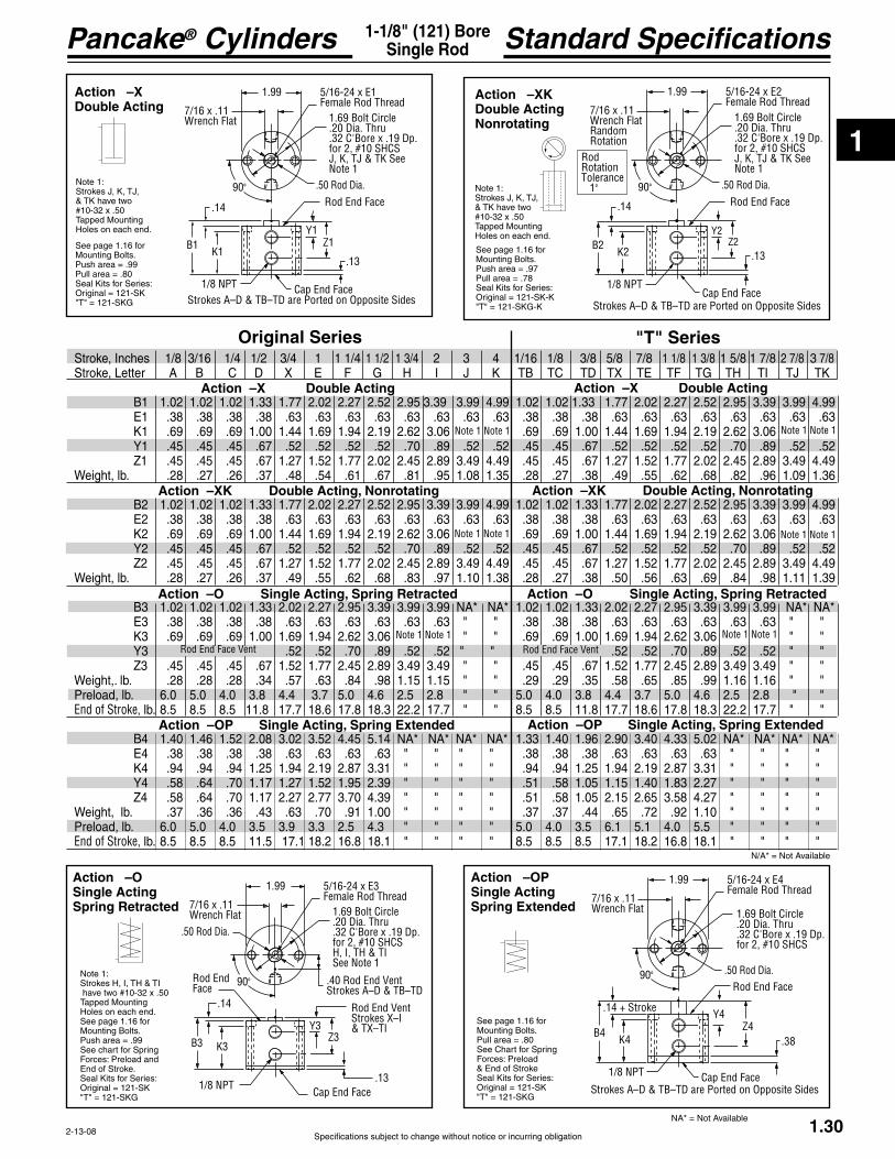
Standard Specifications1-1/8" (121) BoreSingle Rod
2-13-08
Note 1 Note 1
Note 1 Note 1 Note 1 Note 1
Note 1 Note 1 Note 1 Note 1
Original Series "T" Series
Action –OP Single Acting, Spring Extended
Action –XDouble Acting
Action –XKDouble ActingNonrotating
See page 1.16 forMounting Bolts.
Seal Kits for Series:
Note 1:
Holes on each end.
Note 1:
Holes on each end.
See page 1.16 forMounting Bolts.
Seal Kits for Series:
Action –OP Single Acting, Spring Extended
Action –O Single Acting, Spring Retracted
Action –XK Double Acting, Nonrotating
Action –X Double Acting Action –X Double Acting
Stroke, Inches 1/8 3/16 1/4 1/2 3/4 1 1 1/4 1 1/2 1 3/4 2 3 4 1/16 1/8 3/8 5/8 7/8 1 1/8 1 3/8 1 5/8 1 7/8 2 7/8 3 7/8
B1 1.02 1.02 1.02 1.33 1.77 2.02 2.27 2.52 2.95 3.39 3.99 4.99 1.02 1.02 1.33 1.77 2.02 2.27 2.52 2.95 3.39 3.99 4.99
K1 .69 .69 .69 1.00 1.44 1.69 1.94 2.19 2.62 3.06 .69 .69 1.00 1.44 1.69 1.94 2.19 2.62 3.06 Y1 .45 .45 .45 .67 .52 .52 .52 .52 .70 .89 .52 .52 .45 .45 .67 .52 .52 .52 .52 .70 .89 .52 .52
Weight, lb. .28 .27 .26 .37 .48 .54 .61 .67 .81 .95 1.08 1.35 .28 .27 .38 .49 .55 .62 .68 .82 .96 1.09 1.36
B2 1.02 1.02 1.02 1.33 1.77 2.02 2.27 2.52 2.95 3.39 3.99 4.99 1.02 1.02 1.33 1.77 2.02 2.27 2.52 2.95 3.39 3.99 4.99
K2 .69 .69 .69 1.00 1.44 1.69 1.94 2.19 2.62 3.06 .69 .69 1.00 1.44 1.69 1.94 2.19 2.62 3.06 Y2 .45 .45 .45 .67 .52 .52 .52 .52 .70 .89 .52 .52 .45 .45 .67 .52 .52 .52 .52 .70 .89 .52 .52
Weight, lb. .28 .27 .26 .37 .49 .55 .62 .68 .83 .97 1.10 1.38 .28 .27 .38 .50 .56 .63 .69 .84 .98 1.11 1.39
B3 1.02 1.02 1.02 1.33 2.02 2.27 2.95 3.39 3.99 3.99 NA* NA* 1.02 1.02 1.33 2.02 2.27 2.95 3.39 3.99 3.99 NA* NA*
K3 .69 .69 .69 1.00 1.69 1.94 2.62 3.06 " " .69 .69 1.00 1.69 1.94 2.62 3.06 " " Y3 .52 .52 .70 .89 .52 .52 " " .52 .52 .70 .89 .52 .52 " "
Weight,. lb. .28 .28 .28 .34 .57 .63 .84 .98 1.15 1.15 " " .29 .29 .35 .58 .65 .85 .99 1.16 1.16 " "Preload, lb. 6.0 5.0 4.0 3.8 4.4 3.7 5.0 4.6 2.5 2.8 " " 5.0 4.0 3.8 4.4 3.7 5.0 4.6 2.5 2.8 " " End of Stroke, lb. 8.5 8.5 8.5 11.8 17.7 18.6 17.8 18.3 22.2 17.7 " " 8.5 8.5 11.8 17.7 18.6 17.8 18.3 22.2 17.7 " "
B4 1.40 1.46 1.52 2.08 3.02 3.52 4.45 5.14 NA* NA* NA* NA* 1.33 1.40 1.96 2.90 3.40 4.33 5.02 NA* NA* NA* NA*
K4 .94 .94 .94 1.25 1.94 2.19 2.87 3.31 " " " " .94 .94 1.25 1.94 2.19 2.87 3.31 " " " " Y4 .58 .64 .70 1.17 1.27 1.52 1.95 2.39 " " " " .51 .58 1.05 1.15 1.40 1.83 2.27 " " " "
Weight, lb. .37 .36 .36 .43 .63 .70 .91 1.00 " " " " .37 .37 .44 .65 .72 .92 1.10 " " " "Preload, lb. 6.0 5.0 4.0 3.5 3.9 3.3 2.5 4.3 " " " " 5.0 4.0 3.5 6.1 5.1 4.0 5.5 " " " "End of Stroke, lb. 8.5 8.5 8.5 11.5 17.1 18.2 16.8 18.1 " " " " 8.5 8.5 8.5 17.1 18.2 16.8 18.1 " " " "
Rod End Face VentRod End Face Vent
5/16-24 x E1Female Rod Thread
1.69 Bolt Circle .20 Dia. Thru.32 C'Bore x .19 Dp.for 2, #10 SHCSJ, K, TJ & TK SeeNote 1
1.99
7/16 x .11Wrench Flat
.50 Rod Dia.90°
.14
B1K1
1/8 NPT
Rod End Face
Y1Z1
Cap End Face
.13
Strokes A–D & TB–TD are Ported on Opposite Sides
5/16-24 x E2Female Rod Thread
1.69 Bolt Circle .20 Dia. Thru.32 C'Bore x .19 Dp.for 2, #10 SHCSJ, K, TJ & TK SeeNote 1
1.99
7/16 x .11Wrench FlatRandom Rotation
.50 Rod Dia.90°
.14
B2K2
1/8 NPT
Rod End Face
Y2Z2
Cap End Face
.13
RodRotationTolerance 1°
Strokes A–D & TB–TD are Ported on Opposite Sides
Action –O Single Acting, Spring Retracted
Note 1 Note 1
Action –OPSingle ActingSpring Extended
See page 1.16 forMounting Bolts.
See Chart for SpringForces: Preload
Seal Kits for Series:
5/16-24 x E4Female Rod Thread
1.69 Bolt Circle .20 Dia. Thru.32 C'Bore x .19 Dp.for 2, #10 SHCS
1.99
7/16 x .11Wrench Flat
.50 Rod Dia.90°
.14 + Stroke
B4K4
1/8 NPT
Rod End Face
Y4Z4
Cap End Face
.38
Strokes A–D & TB–TD are Ported on Opposite Sides
Action –OSingle ActingSpring Retracted
Note 1:
Holes on each end.See page 1.16 forMounting Bolts.
See chart for SpringForces: Preload and
Seal Kits for Series:
5/16-24 x E3Female Rod Thread
1.69 Bolt Circle .20 Dia. Thru.32 C'Bore x .19 Dp.for 2, #10 SHCSH, I, TH & TISee Note 1
.40 Rod End VentStrokes A–D & TB–TD
1.99
7/16 x .11Wrench Flat
.50 Rod Dia.
90°Rod EndFace
.14
B3 K3
1/8 NPT
Rod End VentStrokes X–I& TX–TIY3
Z3
Cap End Face.13
Action –XK Double Acting, Nonrotating
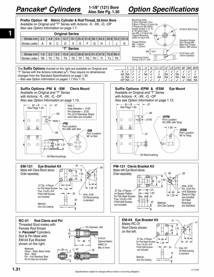
1
Pancake® Cylinders
Specifications subject to change without notice or incurring obligation1.31
Option Specifications1-1/8" (121) BoreAlso See Pg. 1.30
-X -XK NA NA NA NA -O NA NA NA NA NA NA -OP NA NA NA
Suffix Options charted on the right are available on Original and
changes from the Standard Specifications on page 1.30. – Also see Option Information on pages 1.7 thru 1.15.
.37
.57
Oil filled bushing
.81 + B
.56
.30
-EPMPort LocationIN LINE with Tang
-ESMPort Location90° to Tang
See Page 1.30
.3135
1.00
Suffix Options -EPM & -ESM Eye Mount
with Actions: -X, -XK, -O, -OPAlso see Option Information on page 1.13.
.37
.69
1.00
Oil filled bushings
.81 + B
.56
.31 1.21
-PMPort LocationIN LINE with Slot -SM
Port Location90° to Slot
See Page 1.30
Note 1
Note 1:Hole Diameter = .3135Pin Diameter = .3125Pin (416 Stainless Steel) and Clips are included
Suffix Options -PM & -SM Clevis Mount
with Actions: -X, -XK, -O, -OPAlso see Option Information on page 1.13.
Prefix Option -M Metric Cylinder & Rod Thread, 28.5mm Bore
Also see Option Information on page 1.7. 42.8mm Bolt Circle
G1/8 Ports with 14mm Spotface
M8 x 19.0
Standard Female Rod Thread M8.Male Rod ThreadOption -MR shown.
Mounting Holes5.3mm Diameter Thru8.8mm C'Bore x 5.3mm Dp.2 Places for M5 SHCSExcept strokes J, K, TJ& TK which havetwo M5 x 12.0mm Dp.Tapped Mounting Holes on each end.
Thread PitchesM5 = 0.8mmM8 = 1.25mm
Conversion FactorInches x 25.4 = mm
Stroke mm 3.2 4.8 6.4 12.7 19.1 25.4 31.8 38.1 44.5 50.8 76.2 101.6
Stroke mm 1.6 3.2 9.5 15.9 22.2 28.6 34.9 41.3 47.6 73.0 96.4
Original Series
“T” Series
2-13-08
EM-04 Eye Bracket KitMates RC-31 Rod Clevis shown on the left.
EM-121 Eye Bracket Kit Mates with Clevis Mount above.Order separately.
Materials:
Stud – SteelPin – 416 Stainless SteelPin & Clips are included
.25
Pin Diameter .250
5/16-24Optional Metric
m1.16
.88
.96 .50 .39
.75
PM-121 Clevis Bracket Kit
Order separately.
.88 1.131.50
.941.32
Hole .3135Pin .3125 Pin (416 StainlessSteel) & Clipsare included. Oil Filled Bushingsare Standard.
.69.46
1.211.00
.27 Dia. 4 Placeson Square Patternfor Flat Head Screws.
sare included.
.31
.25 Material:
.44.69
1.38
.25
1.50
1.501.13
Hole .3135Oil filled bushingis standard
.30
1.13 .94.27 Dia. 4 Placesfor Flat Head Screws
are included
Material:
.31.41
.87
.16
1.25
1.25.88
Hole .251Oil filled bushingis standard
.23
.88 .56.27 Dia. 4 Placesfor Flat Head Screws
are included
Material:
RC-31 Rod Clevis and Pin
Female Rod thread in Pancake® Cylinders. Slot & Pin Mate with
shown on the right.

1
Specifications subject to change without notice or incurring obligation
Pancake® Cylinders
Sensor Slots atPositions #1 and # 2
Sensor Slot atPosition #1 only
1.32
Option Specifications1-1/8" (121) BoreAlso See Pg. 1.30
1 1/8" (121) Bore
Suffix Option -E Specifies Magnetic Piston and Dovetail Mounting Slot(s) Strokes are NOT affected by magnetic piston.
Quick Reference to Standard StrokesUse the appropriate Stroke Letter in the Model Number
– Sensors Must be Ordered SeparatelySee Sensor Models Available page 1.14
Suffix Option -AS Adjustable Extend StrokeAvailable on Original Series with Actions: -X, -XK, -OAlso see Option Information on page 1.11.
BB C
D
1.50 Dia.
1.13 Dia. .050 Stroke AdjustmentPer Revolution
Stroke Inches 1/8 3/16 1/4 1/2 3/4 1 1-1/4 1-1/2 1-3/4 2 3 4
Actions: -X, -XK BB 1.36 1.36 1.36 1.67 2.11 2.36 2.61 2.86 3.30 3.74 4.33 5.33Actions:-O BB 1.36 1.36 1.36 1.67 2.36 2.61 3.30 3.74 4.33 4.33 NA NA C 1.40 1.53 1.66 2.16 2.66 3.16 3.66 4.16 4.66 5.16 7.16 9.16 D 0.63 0.69 0.75 1.00 1.25 1.50 1.75 2.00 2.25 2.50 3.50 4.50
Suffix Option -RS Adjustable Retract Stroke
with Actions: -X, -XK, -O, -OPAlso see Option Information on page 1.11.
Suffix Option -MR Male Rod ThreadAvailable on Original
Actions: -X, -XK, -O, -OP.Also see Option Information on page 1.8.
.17
.13 + B(-OP Only Use B4 as shown on page 1.30. No additional length is required.)
.042 Stroke AdjustmentPer Revolution
Adjusting Screw
Standard Adjustment is 1"
5/16-24 x 0.75
Suffix Option -F Threaded Nose Mount
with Actions: -X, -XK, -O, -OPAlso see Option Information on page 1.13.
1-14
1.59
.19
1 3/8Hex
Part No. 12100-195Mounting Nut is includedMaterial: Zinc Plated Steel
.14
.25
.75
1.00+ B
1.99
Pilot Dia. 1.000.995
1-14
2-5-08
Available on Original Series Action Stroke X XK
1/2 ------------ D ----- Not Available 3/4 -------------X--------------X 1 ---------------- -------------- 1 1/4 -----------F --------------F 1 1/2 ---------- G ------------ G 1 3/4 ---------- H -------------H 2 ---------------- I -------------- I 3 ----------------J --------------J 4 ----------------K--------------K
Available on“T” Series
Action Stroke X XK
3/8 ----------- ----- Not Available 5/8 ----------- ----------- 7/8 ----------- ----------- 1 1/8 -------- ----------- 1 3/8 -------- ---------- 1 5/8 -------- ----------- 1 7/8 --------- ------------ 2 7/8 ------- ----------- 3 7/8 -------- -----------
Note: Alloy steel mounting bolts may effect sensing. Stainless steel or other non-magnetic bolts are recommended.
1/4" 60° Dovetail Profile of Sensor & Mounting Slot.
40° 40° #1#2
Sensors available for “D” & “TD” strokes and longer. Strokes “D” & “TD” are ported on opposite sides.
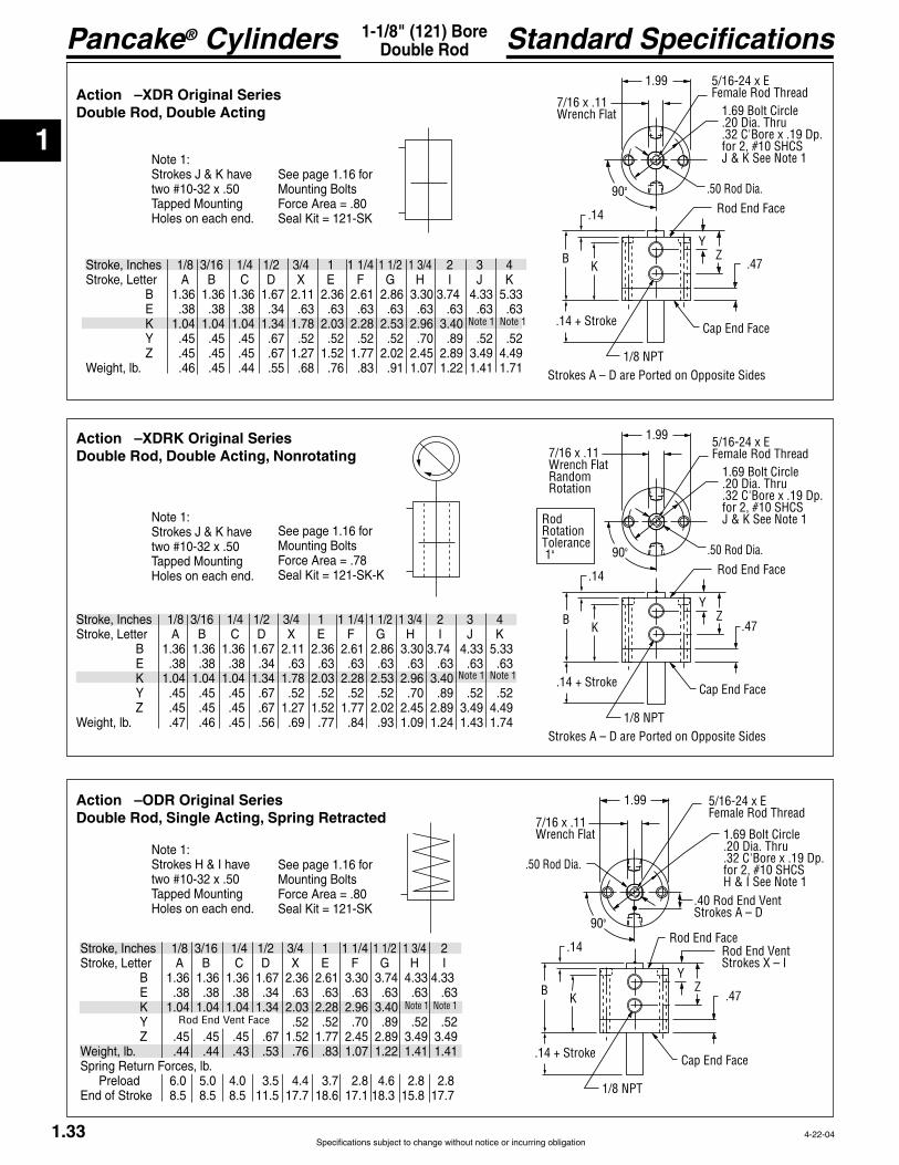
1
Pancake® Cylinders
Specifications subject to change without notice or incurring obligation1.33
1-1/8" (121) BoreDouble Rod Standard Specifications
4-22-04
Action –XDR Original SeriesDouble Rod, Double Acting
Action –XDRK Original SeriesDouble Rod, Double Acting, Nonrotating
Action –ODR Original SeriesDouble Rod, Single Acting, Spring Retracted
Stroke, Inches 1/8 3/16 1/4 1/2 3/4 1 1 1/4 1 1/2 1 3/4 2 3 4
B 1.36 1.36 1.36 1.67 2.11 2.36 2.61 2.86 3.30 3.74 4.33 5.33
K 1.04 1.04 1.04 1.34 1.78 2.03 2.28 2.53 2.96 3.40 Y .45 .45 .45 .67 .52 .52 .52 .52 .70 .89 .52 .52
Weight, lb. .46 .45 .44 .55 .68 .76 .83 .91 1.07 1.22 1.41 1.71
Note 1 Note 1
Stroke, Inches 1/8 3/16 1/4 1/2 3/4 1 1 1/4 1 1/2 1 3/4 2 3 4
B 1.36 1.36 1.36 1.67 2.11 2.36 2.61 2.86 3.30 3.74 4.33 5.33
K 1.04 1.04 1.04 1.34 1.78 2.03 2.28 2.53 2.96 3.40 Y .45 .45 .45 .67 .52 .52 .52 .52 .70 .89 .52 .52
Weight, lb. .47 .46 .45 .56 .69 .77 .84 .93 1.09 1.24 1.43 1.74
Note 1 Note 1
Note 1 Note 1Rod End Vent Face
Stroke, Inches 1/8 3/16 1/4 1/2 3/4 1 1 1/4 1 1/2 1 3/4 2
B 1.36 1.36 1.36 1.67 2.36 2.61 3.30 3.74 4.33 4.33
K 1.04 1.04 1.04 1.34 2.03 2.28 2.96 3.40 Y .52 .52 .70 .89 .52 .52
Weight, lb. .44 .44 .43 .53 .76 .83 1.07 1.22 1.41 1.41 Spring Return Forces, lb. Preload 6.0 5.0 4.0 3.5 4.4 3.7 2.8 4.6 2.8 2.8
Note 1:Strokes J & K have
Holes on each end.
Note 1:Strokes J & K have
Holes on each end.
Note 1:Strokes H & I have
Holes on each end.
See page 1.16 forMounting Bolts
See page 1.16 forMounting Bolts
See page 1.16 forMounting Bolts
5/16-24 x EFemale Rod Thread
1.69 Bolt Circle .20 Dia. Thru.32 C'Bore x .19 Dp.for 2, #10 SHCSJ & K See Note 1
1.997/16 x .11Wrench FlatRandomRotation
.50 Rod Dia.90°
.14
BK
1/8 NPT
Rod End Face
YZ
Cap End Face
.47
Strokes A – D are Ported on Opposite Sides
.14 + Stroke
RodRotationTolerance 1°
5/16-24 x EFemale Rod Thread
1.69 Bolt Circle .20 Dia. Thru.32 C'Bore x .19 Dp.for 2, #10 SHCSJ & K See Note 1
1.99
7/16 x .11Wrench Flat
.50 Rod Dia.90°
.14
BK
1/8 NPT
Rod End Face
YZ
Cap End Face
.47
Strokes A – D are Ported on Opposite Sides
.14 + Stroke
5/16-24 x EFemale Rod Thread
1.69 Bolt Circle .20 Dia. Thru.32 C'Bore x .19 Dp.for 2, #10 SHCSH & I See Note 1
1.99
7/16 x .11Wrench Flat
.50 Rod Dia.
90°
.14
BK
1/8 NPT
Rod End Face
YZ
Cap End Face
.47
.14 + Stroke
Rod End VentStrokes X – I
.40 Rod End VentStrokes A – D

1
Specifications subject to change without notice or incurring obligation
Pancake® Cylinders
Sensor Slot atPosition #1 only
40° 40° #1#2
Sensors available for “D” strokes and longer. Stroke D is ported on opposite sides.
1.34
1-1/8" (121) BoreAlso See Pg. 1.33 Option Specifications
Suffix Options charted on the right are available on Original Series with the Actions indicated (dimensional changes from the Standard Specifications on page 1.33. – Also see Option Information on pages 1.7 thru 1.15.
-XDR -XDRK NA NA NA NA NA -ODR NA NA NA NA NA NA
Quick Reference to Standard StrokesUse the appropriate Stroke Letter in the Model Number
1 1/8" (121) Bore
Available on Original Series Action Stroke XDR XDRK
1/2 ------------ D ----- Not Available 3/4 -------------X--------------X 1 ---------------- -------------- 1 1/4 -----------F --------------F 1 1/2 ---------- G ------------ G 1 3/4 ---------- H -------------H 2 ---------------- I -------------- I 3 ----------------J --------------J 4 ----------------K--------------K
Suffix Option -E Specifies Magnetic Piston and Dovetail Mounting Slot(s) –Sensors Must Be Ordered SeparatelyStrokes are NOT affected by magnetic piston. See Sensor Models Available page 1.14
Suffix Options -MR, -MR1, -MR2 Male Rod Thread
Available on Original Series with Actions -XDR, -XDRK, -ODR.
Also see Option Information on Page 1.8.
5/16-24 x 0.75
Prefix Option -M Metric Cylinder & Rod Thread, 50.8mm BoreAvailable on Original Series with Actions: -XDR, -XDRK, -ODRAlso see Option Information on page 1.7.
42.8mm Bolt Circle
G1/8 Ports with 14mm Spotface
M8 x 19.0
Standard Female Rod Thread M8.Male Rod ThreadOption -MR shown.
Mounting Holes5.3mm Diameter Thru8.8mm C'Bore x 5.3mm Dp.2 Places for M5 SHCSExcept strokes J, K, TJ& TK which havetwo M5 x 12.0mm Dp.Tapped Mounting Holes on each end.
Thread PitchesM5 = 0.8mmM8 = 1.25mm
Conversion FactorInches x 25.4 = mm
Stroke mm 3.2 4.8 6.4 12.7 19.1 25.4 31.8 38.1 44.5 50.8 76.2 101.6
2-5-08
Suffix Options -F, -F1, -F2 Threaded Nose MountAvailable on Original Serieswith Actions -XDR, -XDRK, -ODR.
-F-F1-F2
Also see Option Information page 1.13.
.14 .25.75
.14 +Stroke
1.00+ B
1.99
Pilot Dia. 1.000.995
1-14
1-14
1.59
.19
1 3/8Hex
Part No. 12100-195Mounting Nut is includedMaterial: Zinc Plated Steel
Note: Alloy steel mounting bolts may effect sensing. Stainless steel or other non-magnetic bolts are recommended.
Sensor Slots atPositions #1 and # 2
1/4" 60° Dovetail Profile of Sensor & Mounting Slot.
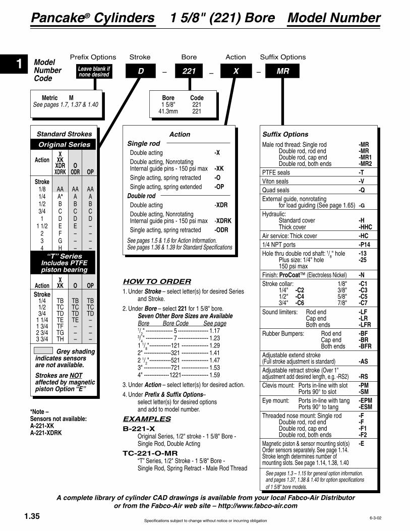
1
Pancake® Cylinders
Specifications subject to change without notice or incurring obligation
ModelNumberCode
Bore Stroke Action
–D –221 – MRLeave blank if none desired
Metric MSee pages 1.7, 1.37 & 1.40
Bore Code 1 5/8" 221 41.3mm 221
X
Model Number1 5/8" (221) Bore
1.35 6-3-02
A complete library of cylinder CAD drawings is available from your local Fabco-Air Distributor or from the Fabco-Air web site – http://www.fabco-air.com
HOW TO ORDER1. Under Stroke – select letter(s) for desired Series and Stroke.
2. Under Bore – select 221 for 1 5/8" bore. Seven Other Bore Sizes are Available Bore Bore Code See page 1/2" --------------- 5 ----------------- 1.17 3/4" --------------- 7 ----------------- 1.23 1 1/8" ------------121 --------------- 1.29 2" ---------------321 --------------- 1.41 2 1/2" ------------521 --------------- 1.47 3" ---------------721 --------------- 1.53 4" --------------1221 --------------- 1.59
3. Under Action – select letter(s) for desired action.
4. Under Prefix & Suffix Options– select letter(s) for desired options and add to model number.
EXAMPLESB-221-X Original Series, 1/2" stroke - 1 5/8" Bore - Single Rod, Double Acting
TC-221-O-MR
Grey shading indicates sensors are not available.
Strokes are NOT affected by magnetic piston Option “E”
Standard Strokes
Original Series X Action XK XDR O XDRK ODR OP Stroke 1/8 AA AA AA 1/4 A* A A 1/2 B B B 3/4 C C C 1 D D D
2 F – – 3 G – – 4 H – –
“T” SeriesIncludes PTFE piston bearing
X Action XK O OP Stroke
Action Single rod Double acting -X Double acting, Nonrotating -XK Single acting, spring retracted -O
-OP Double rod Double acting -XDR Double acting, Nonrotating
XDRK Single acting, spring retracted -ODR
See pages 1.5 & 1.6 for Action Information. See pages 1.36 & 1.39 for Standard Specifications
See pages 1.3 – 1.15 for general option information. and pages 1.37, 1.38 & 1.40 for option specifications of 1 5/8" bore models.
Suffix Options
Male rod thread: Single rod -MR Double rod, rod end -MR Double rod, cap end -MR1 Double rod, both ends -MR2
-T-V
Quad seals -Q
for load guiding (See page 1.65) -GHydraulic: Standard cover -H
-HHC-HC-P14
Hole thru double rod shaft: 1/8" hole -13 -25
Finish: ProCoat™ -NStroke collar: 1/8" -C1 1/4" -C2 3/8" -C3 1/2" -C4 5/8" -C5 3/4" -C6 7/8" -C7Sound limiters: Rod end -LF Cap end -LR Both ends -LFRRubber Bumpers: Rod end -BF Cap end -BR Both ends -BFR
(Full stroke adjustment is standard) -ASAdjustable retract stroke (Over 1" adjustment add desired length, e.g. -RS2) -RSClevis mount: Ports in-line with slot -PM Ports 90° to slot -SM
-EPM Ports 90° to tang -ESM
-F Double rod, rod end -F Double rod, cap end -F1 Double rod, both ends -F2Magnetic piston & sensor mounting slot(s) -EOrder sensors separately. See page 1.14. Stroke length determines number of mounting slots. See page 1.14, 1.38, 1.40
*Note – Sensors not available:A-221-XKA-221-XDRK

1
Specifications subject to change without notice or incurring obligation
Pancake® Cylinders
1.36
1-5/8" (221) BoreSingle Rod Standard Specifications
Action –X Double Acting
Action –O Single Acting, Spring Retracted
2-13-08
Original Series "T" Series
Action –OSingle ActingSpring Retracted
Action –OPSingle ActingSpring Extended
Action –XDouble Acting
Action –XKDouble ActingNonrotating
See page 1.16 forMounting Bolts.
Seal Kits for Series:
See page 1.16 forMounting Bolts.
Seal Kits for Series:
Action –OP Single Acting, Spring Extended
Action –O Single Acting, Spring Retracted
Action –XK Double Acting, Nonrotating
Action –X Double Acting
3/8-24 x E3Female Rod Thread
2.38 Bolt Circle .20 Dia. Thru.32 C'Bore x .19 Dp.for 2, #10 SHCS
2.741/2 x .11Wrench Flat
.62 Rod Dia.
.14
B3 K3
1/8 NPT
Rod End Face
Y3Z3
Cap End Face
.13
.66 Rod End VentStrokes AA-D & TB - TD
Rod End VentStrokes E & TE
90°
Rod End Face VentRod End Face Vent
See page 1.16 forMounting Bolts.
See Chart for SpringForces: Preload
Seal Kits for Series:
3/8-24 x E1Female Rod Thread2.38 Bolt Circle .20 Dia. Thru.32 C'Bore x .19 Dp.for 2, #10 SHCS
2.741/2 x .11Wrench Flat
.62 Rod Dia..14
B1K1
1/8 NPT
Rod End Face
Y1Z1
Cap End Face
.13
Strokes AA–A are Ported on Opposite Sides
90°
3/8-24 x E2Female Rod Thread
2.38 Bolt Circle .20 Dia. Thru.32 C'Bore x .19 Dp.for 2, #10 SHCS
2.741/2 x .11Wrench FlatRandom Rotation
.62 Rod Dia.
.14
B2K2
1/8 NPT
Rod End Face
Y2Z2
Cap End Face
.25
RodRotationTolerance 1°
Strokes AA–A are Ported on Opposite Sides
90°
3/8-24 x E4Female Rod Thread
2.38 Bolt Circle .20 Dia. Thru.32 C'Bore x .19 Dp.for 2, #10 SHCS
2.741/2 x .11Wrench Flat
.62 Rod Dia.
.14 + Stroke
B4K4
1/8 NPT
Y4Z4
Cap End Face
For StrokesAA-C = .50D = .63TB-TC = .50TD = .63
Strokes AA–A are Ported on Opposite Sides
Rod End Face90°
Stroke, Inches 1/8 1/4 1/2 3/4 1 1 1/2 2 3 4 1/4 1/2 3/4 1 1/4 1 3/4 2 3/4 3 3/4
B1 1.14 1.27 1.77 2.02 2.33 2.83 3.33 4.33 5.33 1.77 2.02 2.33 2.83 3.33 4.33 5.33
K1 .81 .94 1.44 1.69 2.00 2.50 3.00 4.00 5.00 1.44 1.69 2.00 2.50 3.00 4.00 5.00 Y1 .64 .64 .52 .52 .52 .52 .52 .52 .52 .52 .52 .52 .52 .52 .52 .52
Weight, lb. .60 .64 .93 1.06 1.19 1.43 1.66 2.14 2.60 .99 1.12 1.25 1.49 1.72 2.20 2.66
B2 1.27 1.40 1.90 2.15 2.46 2.96 3.46 4.46 5.46 1.90 2.15 2.46 2.96 3.46 4.46 5.46
K2 .94 1.06 1.57 1.82 2.13 2.63 3.13 4.13 5.13 1.57 1.82 2.13 2.63 3.13 4.13 5.13 Y2 .64 .64 .52 .52 .52 .52 .52 .52 .52 .52 .52 .52 .52 .52 .52 .52
Weight, lb. .68 .72 1.02 1.15 1.29 1.53 1.77 2.27 2.74 1.08 1.21 1.35 1.59 1.83 2.83 3.80
B3 1.14 1.27 1.77 2.02 2.33 4.33 NA* NA* NA* 1.77 2.02 2.33 4.33 NA* NA* NA*
K3 .81 .94 1.44 1.69 2.00 4.00 NA* NA* NA* 1.44 1.69 2.00 4.00 NA* NA* NA* Y3 .52 NA* NA* NA* .52 NA* NA* NA*
Weight,. lb. .58 .63 .89 1.00 1.15 2.10 NA* NA* NA* .95 1.06 1.21 2.16 NA* NA* NA* Preload, lb. 15.0 8.5 8.5 6.0 4.8 6.0 NA* NA* NA* 8.5 8.5 6.0 7.06 NA* NA* NA* End of Stroke, lb. 20.0 20.0 20.0 18.0 20.0 18.0 NA* NA* NA* 20.0 20.0 18.0 20.0 NA* NA* NA*
B4 1.65 1.89 2.64 3.14 3.83 NA* NA* NA* NA* 2.39 2.89 3.58 NA* NA* NA* NA*
K4 1.19 1.32 1.82 2.07 2.50 NA* NA* NA* NA* 1.82 2.07 2.50 NA* NA* NA* NA* Y4 .77 .89 1.02 1.27 1.52 NA* NA* NA* NA* .77 1.02 1.27 NA* NA* NA* NA*
Weight, lb. .81 .83 1.10 1.20 1.42 NA* NA* NA* NA* 1.16 1.26 1.48 NA* NA* NA* NA*Preload, lb. 8.5 4.5 5.5 4.0 4.8 NA* NA* NA* NA* 4.5 5.5 4.0 NA* NA* NA* NA*End of Stroke, lb. 15.0 15.0 18.5 17.5 20.0 NA* NA* NA* NA* 15.0 18.5 17.5 NA* NA* NA* NA*
Action –XK Double Acting, Nonrotating
Action –OP Single Acting, Spring Extended
See page 1.16 forMounting Bolts.
See Chart for SpringForces: Preload
Seal Kits for Series:
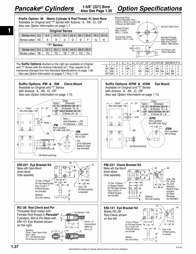
1
Pancake® Cylinders
Specifications subject to change without notice or incurring obligation1.37
Option Specifications1-5/8" (221) BoreAlso See Page 1.36
.37
.60
Oil filled bushing
Chart
.68
.35
-EPMPort LocationIN LINE with Tang
-ESMPort Location90° to Tang
Also see page 1.36
.376
1.25
ChartAction-X, -O-XK-OP-OP
DimensionAll Strokes .88 + BAll Strokes .75 + B
AA-C Strokes .94 + BD Stroke .81 + B
.37
.69
1.25
Oil filled bushings
Chart
.68
.38 1.48
-PMPort LocationIN LINE with Slot -SM
Port Location90° to Slot
Also see page 1.36
Note 1
Pin (416 Stainless Steel) & Clips are included
ChartAction-X, -O-XK-OP-OP
DimensionAll Strokes .88 + BAll Strokes .75 + B
AA-C Strokes .94 + BD Stroke .81 + B
Note 1:Hole Diameter = .376Pin Diameter = .3750
6-6-05
Suffix Options -PM & -SM Clevis Mount
with Actions: -X, -XK, -O, -OPAlso see Option Information on page 1.13.
Suffix Options -EPM & -ESM Eye Mount
with Actions: -X, -XK, -O, -OPAlso see Option Information on page 1.13.
Prefix Option -M Metric Cylinder & Rod Thread, 41.3mm Bore
Also see Option Information on page 1.7. 60.3mm Bolt Circle
G1/8 Ports with 14mm Spotface
M10 x 22.2
Standard Female Rod Thread M10.Male Rod ThreadOption -MR shown.
Mounting Holes5.3mm Diameter Thru8.8mm C'Bore x 5.3mm Dp.2 Places for M5 SHCS
Thread PitchesM5 = 0.8mmM10 = 1.5mm
Conversion FactorInches x 25.4 = mm
Stroke mm 3.2 6.4 12.7 19.1 25.4 38.1 50.8 76.2 101.6
Stroke mm 6.4 12.7 19.1 31.8 44.5 69.9 95.3
Original Series
“T” Series
EM-121 Eye Bracket KitMates RC-38 Rod Clevis shownon the left.
EM-221 Eye Bracket Kit Mates with Clevis Mount shown above.Order separately.
.32
Pin Diameter .3125
Optional Metric1.63
1.25
1.21 .63 . 61
1.00
Materials:
Stud – SteelPin – 416 Stainless SteelPin & Clips are included
PM-221 Clevis Bracket Kit
shown above.Order separately. 1.25 1.50
2.00
1.001.38
Hole .376Pin .3750Pin (416StainlessSteel) & Clipsincluded. Oil Filled Bushingsare Standard.
.69.52
1.481.25
.27 Dia. 4 Placeson Square Patternfor Flat Head Screws.
FHSCS Screwsare included.
.38
.31Material:
.56.81
1.69
.31
2.00
2.001.50
Hole .376Oil filled bushingis standard
.36
1.50 1.13.27 Dia. 4 Placesfor Flat Head Screws
FHSCS Screwsare included
Material:
.44.69
1.38
.25
1.50
1.501.13
Hole .3135Oil filled bushingis standard
.30
1.13 .94.27 Dia. 4 Placesfor Flat Head Screws
are included
Material:
Suffix Options charted on the right are available on Original -
mensional changes from the Standard Specifications on page 1.36. – Also see Option Information on pages 1.7 thru 1.15.
-X -XK NA NA NA NA -O NA NA NA NA NA NA -OP NA NA NA
RC-38 Rod Clevis and Pin
Female Rod thread in Pancake® Cylinders. Slot & Pin Mate with
on the right.
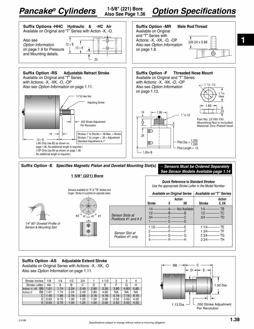
1
Specifications subject to change without notice or incurring obligation
Pancake® Cylinders
1.38
Option Specifications1-5/8" (221) BoreAlso See Page 1.36
45°45° #1#2
Sensors available for “A” & “TB” strokes and longer. Stroke A is ported on opposite sides.
1 5/8" (221) Bore
Suffix Option -E Specifies Magnetic Piston and Dovetail Mounting Slot(s)
Quick Reference to Standard StrokesUse the appropriate Stroke Letter in the Model Number
Available on Original Series
Action Stroke X XK
1/4 ----------------A-------Not Available 1/2 ----------------B---------------B 3/4 --------------- C --------------C 1 ------------------ D --------------D
1 1/2 -------------- --------------- 2 -------------------F ---------------F 3 ------------------ G ------------- G 4 ------------------ H --------------H
Available on“T” Series
Action Stroke X, XK
1/4 -------------- 1/2 -------------- 3/4 --------------
1 1/4 ------------ 1 3/4 ------------ 2 3/4 ------------ 3 3/4 ------------
– Sensors Must be Ordered SeparatelySee Sensor Models Available page 1.14
2-5-08
Suffix Option -AS Adjustable Extend StrokeAvailable on Original Series with Actions: -X, -XK, -OAlso see Option Information on page 1.11.
BB C
D
1.50 Dia.
1.13 Dia. .050 Stroke AdjustmentPer Revolution
Stroke Inches 1/8 1/4 1/2 3/4 1 1-1/2 2 3 4
Actions: -X, -XK BB 1.61 1.74 2.24 2.49 2.80 3.30 3.80 4.80 5.80Actions:-O BB 1.61 1.74 2.24 2.49 2.80 4.80 NA NA NA C 1.40 1.66 2.16 2.66 3.16 4.16 5.16 7.16 9.16 D 0.63 0.75 1.00 1.25 1.50 2.00 2.50 3.50 4.50
.14
.25
.75
1.00+ B
1.99
Pilot Dia. 1.2501.245
1 1/4-12
Suffix Option -RS Adjustable Retract Stroke
with Actions: -X, -XK, -O, -OPAlso see Option Information on page 1.11.
Suffix Options -HHC Hydraulic & -HC Air
Also see Option Information on page 1.9 for Pressureand Mounting details.
Suffix Option -MR Male Rod ThreadAvailable on Original
Actions: -X, -XK, -O, -OP.Also see Option Information on page 1.8.
.19
.13 + B(-XK Only Use B2 as shown on page 1.36. No additional length is required.)(-OP Only Use B4 as shown on page 1.36. No additional length is required.)
.050 Stroke AdjustmentPer Revolution
Adjusting Screw
Standard Adjustment is 1"
3/8-24 x 0.88.12 + B
.12 + K
.25
Suffix Option -F Threaded Nose Mount
with Actions: -X, -XK, -O, -OPAlso see Option Information on page 1.13.
1 1/4 -12
1.88
.25
1 5/8Hex
Part No. 22100-195Mounting Nut is includedMaterial: Zinc Plated Steel
Sensor Slots atPositions #1 and # 2
Sensor Slot atPosition #1 only
1/4" 60° Dovetail Profile of Sensor & Mounting Slot.

1
Pancake® Cylinders
Specifications subject to change without notice or incurring obligation1.39
Standard Specifications1-5/8" (221) BoreDouble Rod
Action –XDR Original SeriesDouble Rod, Double Acting
Action –XDRK Original SeriesDouble Rod, Double Acting, Nonrotating
Action –ODR Original SeriesDouble Rod, Single Acting, Spring Retracted
Rod End Vent Face
Stroke, Inches 1/8 1/4 1/2 3/4 1 1 1/2
B 1.61 1.74 2.24 2.49 2.80 4.80
K 1.28 1.41 1.91 2.16 2.47 4.47 Y .52
Weight, lb. .95 1.01 1.30 1.42 1.58 1.86Spring Return Forces, lb. Preload 15.0 8.5 8.5 6.0 4.8 6.0
Stroke, Inches 1/8 1/4 1/2 3/4 1 1 1/2 2 3 4
B 1.61 1.74 2.24 2.49 2.80 3.30 3.80 4.80 5.80
K 1.28 1.41 1.91 2.16 2.47 2.97 3.47 4.47 5.47 Y .64 .64 .52 .52 .52 .52 .52 .52 .52
Weight, lb. 1.05 1.11 1.44 1.55 1.73 2.01 2.30 2.86 3.42
Stroke, Inches 1/8 1/4 1/2 3/4 1 1 1/2 2 3 4
B 1.61 1.74 2.24 2.49 2.80 3.30 3.80 4.80 5.80
K 1.28 1.41 1.91 2.16 2.47 2.97 3.47 4.47 5.47 Y .64 .64 .52 .52 .52 .52 .52 .52 .52
Weight, lb. .97 1.03 1.35 1.46 1.63 1.91 2.19 2.73 3.28
4-22-04
See page 1.16 forMounting Bolts
See page 1.16 forMounting Bolts
See page 1.16 forMounting Bolts
3/8-24 x EFemale Rod Thread2.38 Bolt Circle .20 Dia. Thru.32 C'Bore x .19 Dp.for 2, #10 SHCS
2.741/2 x .11Wrench FlatRandomRotation
.62 Rod Dia..14
BK
1/8 NPT
Rod End Face
YZ
Cap End Face
.60
Strokes AA–A are Ported on Opposite Sides
90°
.14 + Stroke
RodRotationTolerance 1°
3/8-24 x EFemale Rod Thread2.38 Bolt Circle .20 Dia. Thru.32 C'Bore x .19 Dp.for 2, #10 SHCS
2.741/2 x .11Wrench Flat
.62 Rod Dia..14
BK
1/8 NPT
Rod End Face
YZ
Cap End Face
.60
Strokes AA–A are Ported on Opposite Sides
90°
.14 + Stroke
3/8-24 x EFemale Rod Thread
2.38 Bolt Circle .20 Dia. Thru.32 C'Bore x .19 Dp.for 2, #10 SHCS
2.74
1/2 x .11Wrench Flat
.62 Rod Dia.
.14
BK
1/8 NPT
Rod End Face
YZ
Cap End Face
.60
90°
.14 + Stroke
.66 Rod End VentStrokes AA–D
Rod End VentStroke E

1
Specifications subject to change without notice or incurring obligation
Pancake® Cylinders
45°45° #1#2
Sensors available for “A”strokes and longer. Stroke A is ported on opposite sides.
1.40
Option Specifications1-5/8" (221) BoreAlso See Page 1.39
Suffix Options -F, -F1, -F2 Threaded Nose MountAvailable on Original Serieswith Actions -XDR, -XDRK, -ODR.
-F-F1
-F2Also see Option Information on page 1.13.
Suffix Options charted on the right are available on Original Series with the Actions indicated (dimensional changes from the Standard Specifications on page 1.39. – Also see Option Information on pages 1.7 thru 1.15.
-XDR -XDRK NA NA NA NA -ODR NA NA NA NA NA NA
Suffix Option -E Specifies Magnetic Piston and Dovetail Mounting Slot(s)Strokes are NOT affected by magnetic piston.
Quick Reference to Standard StrokesUse the appropriate Stroke Letter in the Model Number
1 5/8" (221) Bore
Available on Original Series
Action Stroke XDR XDRK
1/4 ----------------A-------Not Available 1/2 ----------------B---------------B 3/4 --------------- C --------------C 1 ------------------ D --------------D 1 1/2 -------------- --------------- 2 -------------------F ---------------F 3 ------------------ G ------------- G 4 ------------------ H --------------H
– Sensors Must be Ordered SeparatelySee Sensor Models Available page 1.14
Prefix Option -M Metric Cylinder & Rod Thread, 41.3mm BoreAvailable on Original Series with Actions: -XDR, -XDRK, -ODRAlso see Option Information on page 1.7.
60.3mm Bolt Circle
G1/8 Ports with 14mm Spotface
M10 x 22.2
Standard Female Rod Thread M10.Male Rod ThreadOption -MR shown.
Mounting Holes5.3mm Diameter Thru8.8mm C'Bore x 5.3mm Dp.2 Places for M5 SHCS
Thread PitchesM5 = 0.8mmM10 = 1.5mm
Conversion FactorInches x 25.4 = mm
Stroke mm 3.2 6.4 12.7 19.1 25.4 38.1 50.8 76.2 101.6
Suffix Options -MR, -MR1, -MR2 Male Rod Thread
Available on Original Series with Actions -XDR, -XDRK, -ODR.
Also see Option Information on Page 1.8.
3/8-24 x 0.88
1 1/4 -12
1.88
.25
1 5/8Hex
Part No. 22100-195Mounting Nut is includedMaterial: Zinc Plated Steel
.14 .25.75
.14 +Stroke
1.00+ B
1.99
Pilot Dia. 1.2501.245
1 1/4 - 12
2-5-08
Sensor Slots atPositions #1 and # 2
Sensor Slot atPosition #1 only
1/4" 60° Dovetail Profile of Sensor & Mounting Slot.
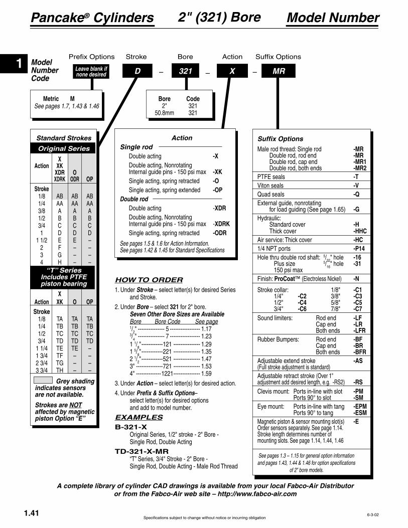
1
Pancake® Cylinders
Specifications subject to change without notice or incurring obligation
ModelNumberCode
Bore Stroke Action
–D –321 –X MRLeave blank if none desired
Metric MSee pages 1.7, 1.43 & 1.46
Bore Code 2" 321 50.8mm 321
Model Number2" (321) Bore
1.41
A complete library of cylinder CAD drawings is available from your local Fabco-Air Distributor or from the Fabco-Air web site – http://www.fabco-air.com
HOW TO ORDER1. Under Stroke – select letter(s) for desired Series and Stroke.
2. Under Bore – select 321 for 2" bore. Seven Other Bore Sizes are Available Bore Bore Code See page 1/2" --------------- 5 ----------------- 1.17 3/4" --------------- 7 ----------------- 1.23 1 1/8" ------------121 --------------- 1.29 1 5/8" ------------221 --------------- 1.35 2 1/2" ------------521 --------------- 1.47 3" ---------------721 --------------- 1.53 4" --------------1221 --------------- 1.59
3. Under Action – select letter(s) for desired action.
4. Under Prefix & Suffix Options– select letter(s) for desired options and add to model number.
EXAMPLESB-321-X Original Series, 1/2" stroke - 2" Bore - Single Rod, Double Acting
TD-321-X-MR
Action Single rod Double acting -X Double acting, Nonrotating -XK Single acting, spring retracted -O
-OP Double rod Double acting -XDR Double acting, Nonrotating
XDRK Single acting, spring retracted -ODR
See pages 1.5 & 1.6 for Action Information. See pages 1.42 & 1.45 for Standard Specifications
Grey shading indicates sensors are not available.
Strokes are NOT affected by magnetic piston Option “E”
Standard Strokes
Original Series
X Action XK XDR O XDRK ODR OP Stroke 1/8 AB AB AB 1/4 AA AA AA 3/8 A A A 1/2 B B B 3/4 C C C 1 D D D
2 F – – 3 G – – 4 H – –
“T” SeriesIncludes PTFE piston bearing
X Action XK O OP Stroke
6-3-02
See pages 1.3 – 1.15 for general option information and pages 1.43, 1.44 & 1.46 for option specifications
of 2" bore models.
Suffix Options
Male rod thread: Single rod -MR Double rod, rod end -MR Double rod, cap end -MR1 Double rod, both ends -MR2
-T -V
Quad seals -Q
for load guiding (See page 1.65) -GHydraulic: Standard cover -H
-HHC -HC -P14
Hole thru double rod shaft: 5/32" hole -16 5/16" hole -31
Finish: ProCoat™ -N
Stroke collar: 1/8" -C1 1/4" -C2 3/8" -C3 1/2" -C4 5/8" -C5 3/4" -C6 7/8" -C7Sound limiters: Rod end -LF Cap end -LR Both ends -LFRRubber Bumpers: Rod end -BF Cap end -BR Both ends -BFR
-AS(Full stroke adjustment is standard)Adjustable retract stroke (Over 1" adjustment add desired length, e.g. -RS2) -RSClevis mount: Ports in-line with slot -PM Ports 90° to slot -SM
-EPM Ports 90° to tang -ESMMagnetic piston & sensor mounting slot(s) -EOrder sensors separately. See page 1.14.Stroke length determines number of mounting slots. See page 1.14, 1.44, 1.46

1
Specifications subject to change without notice or incurring obligation
Pancake® Cylinders
1.42
Standard Specifications2" (321) BoreSingle Rod
Action –XDouble Acting
Action –XKDouble ActingNonrotating
See page 1.16 forMounting Bolts.
Seal Kits for Series:
See page 1.16 forMounting Bolts.
Seal Kits for Series:
Action –OPSingle ActingSpring Extended
See page 1.16 forMounting Bolts.
See Chart for SpringForces: Preload
Seal Kits for Series:
1/2-20 x E1Female Rod Thread2.81 Bolt Circle .27 Dia. Thru.38 C'Bore x .26 Dp.for 2, 1/4" SHCS
3.245/8 x .11Wrench Flat
.75 Rod Dia.72°.14
B1K1
1/8 NPT
Rod End Face
Y1Z1
Cap End Face
.13
Strokes AB–A & TA are Ported on Opposite Sides
1/2-20 x E2Female Rod Thread
2.81 Bolt Circle .27 Dia. Thru.38 C'Bore x .26 Dp.for 2, 1/4" SHCS
3.245/8 x .11Wrench FlatRandom Rotation
.75 Rod Dia.
.14
B2K2
1/8 NPT
Rod End Face
Y2Z2
Cap End Face
.25
RodRotationTolerance 1°
Strokes AB–A & TA are Ported on Opposite Sides
72°
1/2-20 x E4Female Rod Thread
2.81 Bolt Circle .27 Dia. Thru.38 C'Bore x .26 Dp.for 2, 1/4" SHCS
3.245/8 x .11Wrench Flat
.75 Rod Dia.72°
.14 + Stroke
B4K4
1/8 NPT
Y4Z4
Cap End Face
StrokesAB-C = .50D = .63TA-TC = .50TD = .63
Strokes AB–A & TA are Ported on Opposite Sides
Rod End Face
2-18-08
1/2-20 x E3Female Rod Thread2.81 Bolt Circle .27 Dia. Thru.38 C'Bore x .26 Dp.for 2, 1/4" SHCS
3.245/8 x .11Wrench Flat
.75 Rod Dia.
72°
.14
B3 K3
1/8 NPT
Rod End Face
Y3Z3
Cap End Face
.13
.71 Rod End VentStrokes AB-D & TA - TD
Rod End VentStrokes E & TE
Action –OSingle ActingSpring Retracted
See page 1.16 forMounting Bolts.
See Chart for SpringForces: Preload
Seal Kits for Series:
Action –X Double Acting
Original Series "T" Series
Action –XK Double Acting, Nonrotating
Action –X Double Acting
Stroke, Inches 1/8 1/4 3/8 1/2 3/4 1 1 1/2 2 3 4 1/8 1/4 1/2 3/4 1 1/4 1 3/4 2 3/4 3 3/4
B1 1.20 1.33 1.45 1.64 2.02 2.39 2.89 3.39 4.39 5.39 1.45 1.64 2.02 2.39 2.89 3.39 4.39 5.39
K1 .80 .93 1.05 1.24 1.62 1.99 2.49 2.99 3.99 4.99 1.05 1.24 1.62 1.99 2.49 2.99 3.99 4.99 Y1 .52 .52 .52 .52 .52 .52 .52 .52 .52 .52 .52 .52 .52 .52 .52 .52 .52 .52
Weight, lb. .89 .96 1.04 1.16 1.45 1.70 2.02 2.34 2.97 3.58 1.10 1.30 1.56 1.84 2.16 2.48 3.11 3.71
B2 1.33 1.46 1.58 1.77 2.15 2.52 3.02 3.52 4.52 5.52 1.58 1.77 2.15 2.52 3.02 3.52 4.52 5.52
K2 .93 1.06 1.18 1.37 1.75 2.12 2.62 3.12 4.12 5.12 1.18 1.37 1.75 2.12 2.62 3.12 4.12 5.12 Y2 .52 .52 .52 .52 .52 .52 .52 .52 .52 .52 .52 .52 .52 .52 .52 .52 .52 .52
Weight, lb. 1.02 1.09 1.18 1.30 1.60 1.85 2.19 2.52 3.18 3.82 1.24 1.44 1.71 2.00 2.33 2.66 3.32 3.95
B3 1.20 1.33 1.45 1.64 2.02 2.39 4.39 NA* NA* NA* 1.45 1.64 2.02 2.39 4.39 NA* NA* NA*
K3 .80 .93 1.05 1.24 1.62 1.99 3.99 NA* NA* NA* 1.05 1.24 1.62 1.99 3.99 NA* NA* NA* Y3 .52 NA* NA* NA* .52 NA* NA* NA*
Weight,. lb. .85 .97 1.01 1.13 1.36 1.61 3.11 NA* NA* NA* 1.01 1.13 1.36 1.61 3.25 NA* NA* NA* Preload, lb. 12.0 6.2 12.0 7.0 5.0 4.7 5.0 NA* NA* NA* 11.3 7.3 6.2 7.6 4.8 NA* NA* NA* End of Stroke, lb. 18.0 18.0 21.0 20.0 15.5 20.0 20.0 NA* NA* NA* 21.0 20.0 15.5 20.0 20.0 NA* NA* NA* B4 1.71 1.96 2.21 2.52 3.14 3.89 NA* NA* NA* NA* 1.96 2.27 2.89 3.61 NA* NA* NA* NA*
K4 1.18 1.30 1.43 1.62 1.99 2.49 NA* NA* NA* NA* 1.43 1.62 1.99 2.49 NA* NA* NA* NA* Y4 .65 .77 .90 1.02 1.27 1.52 NA* NA* NA* NA* .65 .77 1.02 1.25 NA* NA* NA* NA*
Weight, lb. 1.22 1.29 1.36 1.49 1.76 2.13 NA* NA* NA* NA* 1.50 1.63 1.89 2.26 NA* NA* NA* NA*Preload, lb. 8.5 4.5 9.5 7.0 6.0 4.7 NA* NA* NA* NA* 10.7 7.0 6.0 4.7 NA* NA* NA* NA*End of Stroke, lb. 15.0 15.0 20.0 20.0 18.0 20.0 NA* NA* NA* NA* 18.0 20.0 18.0 20.0 NA* NA* NA* NA*
Action –XK Double Acting, Nonrotating
Action –OP Single Acting, Spring ExtendedAction –OP Single Acting, Spring Extended
Action –O Single Acting, Spring Retracted
Rod End Face VentRod End Face Vent
Action –O Single Acting, Spring Retracted
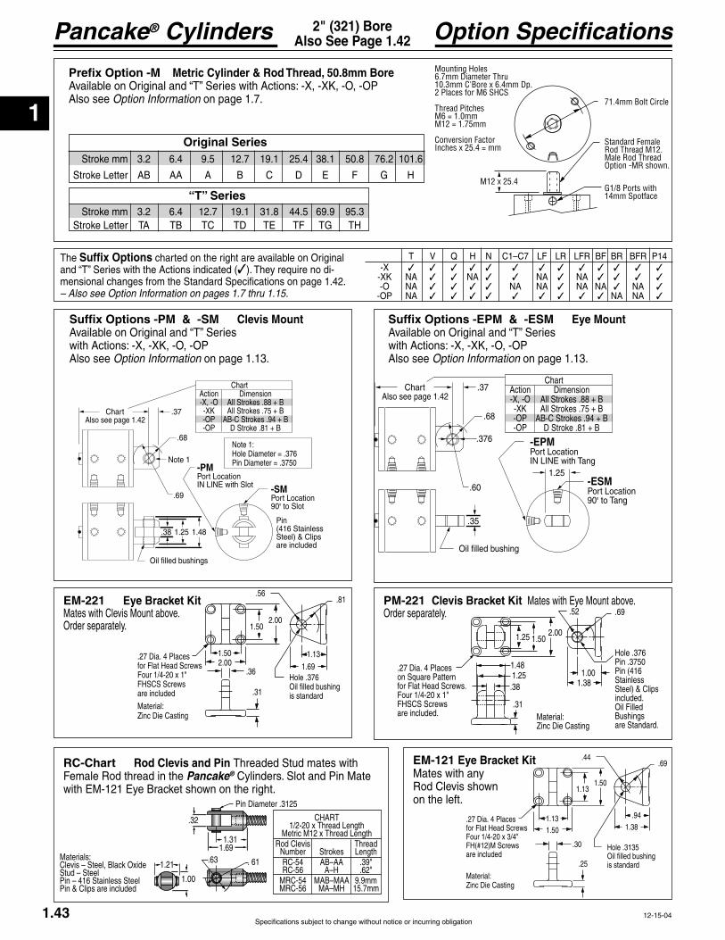
1
Pancake® Cylinders
Specifications subject to change without notice or incurring obligation1.43
.37
.69
1.25
Oil filled bushings
Chart
.68
.38 1.48
-PMPort LocationIN LINE with Slot -SM
Port Location90° to Slot
Also see page 1.42
Note 1
Pin (416 Stainless Steel) & Clips are included
Note 1:Hole Diameter = .376Pin Diameter = .3750
ChartAction-X, -O-XK-OP-OP
DimensionAll Strokes .88 + BAll Strokes .75 + B
AB-C Strokes .94 + BD Stroke .81 + B
Option Specifications2" (321) BoreAlso See Page 1.42
12-15-04
Suffix Options -PM & -SM Clevis Mount
with Actions: -X, -XK, -O, -OPAlso see Option Information on page 1.13.
.37
.60
Oil filled bushing
Chart
.68
.35
-EPMPort LocationIN LINE with Tang
-ESMPort Location90° to Tang
Also see page 1.42
.376
1.25
ChartAction-X, -O-XK-OP-OP
DimensionAll Strokes .88 + BAll Strokes .75 + B
AB-C Strokes .94 + BD Stroke .81 + B
Suffix Options -EPM & -ESM Eye Mount
with Actions: -X, -XK, -O, -OPAlso see Option Information on page 1.13.
Suffix Options charted on the right are available on Original -
mensional changes from the Standard Specifications on page 1.42. – Also see Option Information on pages 1.7 thru 1.15.
-X -XK NA NA NA NA -O NA NA NA NA NA NA -OP NA NA NA
Prefix Option -M Metric Cylinder & Rod Thread, 50.8mm Bore
Also see Option Information on page 1.7. 71.4mm Bolt Circle
G1/8 Ports with 14mm Spotface
M12 x 25.4
Standard Female Rod Thread M12.Male Rod ThreadOption -MR shown.
Mounting Holes6.7mm Diameter Thru10.3mm C'Bore x 6.4mm Dp.2 Places for M6 SHCS
Thread PitchesM6 = 1.0mmM12 = 1.75mm
Conversion FactorInches x 25.4 = mm
Stroke mm 3.2 6.4 9.5 12.7 19.1 25.4 38.1 50.8 76.2 101.6
Stroke mm 3.2 6.4 12.7 19.1 31.8 44.5 69.9 95.3
Original Series
“T” Series
EM-121 Eye Bracket KitMates with any Rod Clevis shown on the left.
EM-221 Eye Bracket Kit Mates with Clevis Mount above.Order separately.
RC-Chart Rod Clevis and Pin Female Rod thread in the Pancake® Cylinders. Slot and Pin Mate
.32
Pin Diameter .3125
1.691.31
1.21 .63 . 61
1.00
Materials:
Stud – SteelPin – 416 Stainless SteelPin & Clips are included
Rod Clevis NumberRC-54RC-56
MRC-54MRC-56
StrokesAB–AA
A–HMAB–MAA
MA–MH
.39"
.62"9.9mm
15.7mm
PM-221 Clevis Bracket Kit Order separately.
1.25 1.502.00
1.001.38
Hole .376Pin .3750Pin (416StainlessSteel) & Clipsincluded. Oil Filled Bushingsare Standard.
.69.52
1.481.25
.27 Dia. 4 Placeson Square Patternfor Flat Head Screws.
FHSCS Screwsare included.
.38
.31Material:
.56.81
1.69
.31
2.00
2.001.50
Hole .376Oil filled bushingis standard
.36
1.50 1.13.27 Dia. 4 Placesfor Flat Head Screws
FHSCS Screwsare included
Material:
.44.69
1.38
.25
1.50
1.501.13
Hole .3135Oil filled bushingis standard
.30
1.13 .94.27 Dia. 4 Placesfor Flat Head Screws
are included
Material:
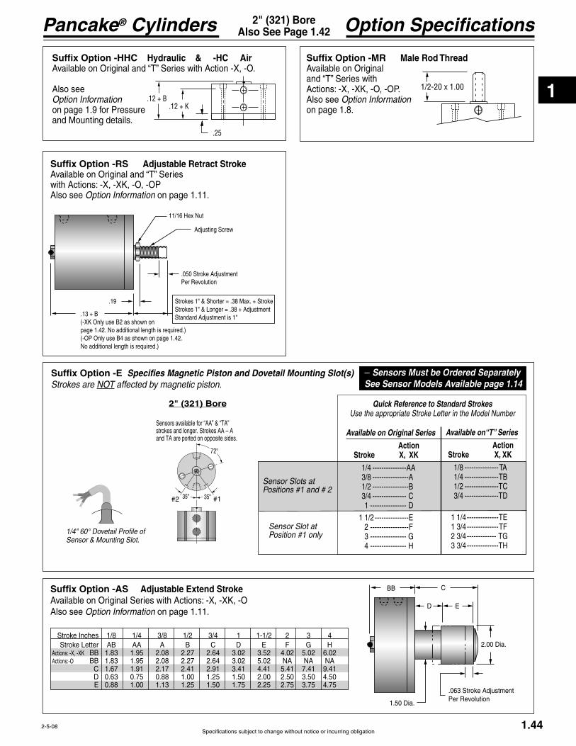
1
Specifications subject to change without notice or incurring obligation
Pancake® Cylinders
72°
35°35° #1#2
Sensors available for “AA” & “TA” strokes and longer. Strokes AA – A and TA are ported on opposite sides.
Sensor Slot atPosition #1 only
1.44
Option Specifications2" (321) BoreAlso See Page 1.42
2" (321) Bore Quick Reference to Standard StrokesUse the appropriate Stroke Letter in the Model Number
Available on Original Series
Action Stroke X, XK
1/4 ---------------AA 3/8 ----------------A 1/2 ----------------B 3/4 --------------- C 1 ---------------- D 1 1/2 --------------- 2 -----------------F 3 ---------------- G 4 ---------------- H
Available on“T” Series
Action Stroke X, XK
1/8 --------------- 1/4 --------------- 1/2 --------------- 3/4 ---------------
1 1/4 -------------- 1 3/4 -------------- 2 3/4 ------------- 3 3/4 --------------
Suffix Option -E Specifies Magnetic Piston and Dovetail Mounting Slot(s)Strokes are NOT affected by magnetic piston.
– Sensors Must be Ordered SeparatelySee Sensor Models Available page 1.14
2-5-08
Suffix Option -AS Adjustable Extend StrokeAvailable on Original Series with Actions: -X, -XK, -OAlso see Option Information on page 1.11.
BB C
D
2.00 Dia.
1.50 Dia.
.063 Stroke AdjustmentPer Revolution
Stroke Inches 1/8 1/4 3/8 1/2 3/4 1 1-1/2 2 3 4
Actions: -X, -XK BB 1.83 1.95 2.08 2.27 2.64 3.02 3.52 4.02 5.02 6.02Actions:-O BB 1.83 1.95 2.08 2.27 2.64 3.02 5.02 NA NA NA C 1.67 1.91 2.17 2.41 2.91 3.41 4.41 5.41 7.41 9.41 D 0.63 0.75 0.88 1.00 1.25 1.50 2.00 2.50 3.50 4.50
Suffix Option -RS Adjustable Retract Stroke
with Actions: -X, -XK, -O, -OPAlso see Option Information on page 1.11.
Suffix Option -HHC Hydraulic & -HC Air
Also see Option Information on page 1.9 for Pressureand Mounting details.
Suffix Option -MR Male Rod ThreadAvailable on Original
Actions: -X, -XK, -O, -OP.Also see Option Information on page 1.8.
.19
.13 + B(-XK Only use B2 as shown on page 1.42. No additional length is required.)(-OP Only use B4 as shown on page 1.42. No additional length is required.)
.050 Stroke AdjustmentPer Revolution
Adjusting Screw
Standard Adjustment is 1"
1/2-20 x 1.00.12 + B
.12 + K
.25
Sensor Slots atPositions #1 and # 2
1/4" 60° Dovetail Profile of Sensor & Mounting Slot.

1
Pancake® Cylinders
Specifications subject to change without notice or incurring obligation1.45
2" (321) BoreDouble Rod Standard Specifications
2-14-08
Action –XDR Original SeriesDouble Rod, Double Acting
Action –XDRK Original SeriesDouble Rod, Double Acting, Nonrotating
Action –ODR Original SeriesDouble Rod, Single Acting, Spring Retracted
1/2-20 x EFemale Rod Thread
2.81 Bolt Circle .27 Dia. Thru.38 C'Bore x .26 Dp.for 2, 1/4" SHCS
3.245/8 x .11Wrench Flat
.75 Rod Dia.72°.14
B K
1/8 NPTStrokes AB–A are Ported on Opposite Sides
Rod End Face
YZ
Cap End Face
.75
.14 + Stroke
1/2-20 x EFemale Rod Thread
2.81 Bolt Circle .27 Dia. Thru.38 C'Bore x .26 Dp.for 2, 1/4" SHCS
3.245/8 x .11Wrench FlatRandomRotation
.75 Rod Dia.72°.14
B K
1/8 NPTStrokes AB–A are Ported on Opposite Sides
Rod End Face
YZ
Cap End Face
.75
.14 + Stroke
RodRotationTolerance 1°
1/2-20 x EFemale Rod Thread2.81 Bolt Circle .27 Dia. Thru.38 C'Bore x .26 Dp.for 2, 1/4" SHCS
3.245/8 x .11Wrench Flat
.75 Rod Dia.72°
.14
B K
1/8 NPT
Rod End Face
YZ
Cap End Face
.75
.14 + Stroke
Rod End VentStroke E
.71 Rod End VentStrokes AB – D
Stroke, Inches 1/8 1/4 3/8 1/2 3/4 1 1-1/2 2 3 4
B 1.83 1.95 2.08 2.27 2.64 3.02 3.52 4.02 5.02 6.02
K 1.44 1.56 1.69 1.89 2.25 2.63 3.13 3.63 4.63 5.63 Y .52 .52 .52 .52 .52 .52 .52 .52 .52 .52
Weight, lb. 1.56 1.64 1.72 1.86 2.15 2.44 2.80 3.18 3.94 4.72
Stroke, Inches 1/8 1/4 3/8 1/2 3/4 1 1-1/2 2 3 4
B 1.83 1.95 2.08 2.27 2.64 3.02 3.52 4.02 5.02 6.02
K 1.44 1.56 1.69 1.89 2.25 2.63 3.13 3.63 4.63 5.63 Y .52 .52 .52 .52 .52 .52 .52 .52 .52 .52
Weight, lb. 1.70 1.78 1.87 2.01 2.31 2.61 2.98 3.37 4.16 4.97
See page 1.16 forMounting Bolts
See page 1.16 forMounting Bolts
See page 1.16 forMounting Bolts
Stroke, Inches 1/8 1/4 3/8 1/2 3/4 1 1-1/2
B 1.83 1.95 2.08 2.27 2.64 3.02 5.02
K 1.44 1.56 1.69 1.89 2.25 2.63 4.63 Y .52
Weight, lb. 1.51 1.60 1.69 1.81 2.10 2.39 4.16Spring Return Forces, lb.Preload 12.0 6.2 12.0 7.0 5.0 4.7 5.0

1
Specifications subject to change without notice or incurring obligation
Pancake® Cylinders
72°
35°35° #1#2
Sensors available for “AA”strokes and longer. Strokes AA – A are ported on opposite sides.
1.46
Option Specifications2" (321) BoreAlso See Page 1.45
2" (321) Bore Quick Reference to Standard StrokesUse the appropriate Stroke Letter in the Model Number
Suffix Option -E Specifies Magnetic Piston and Dovetail Mounting Slot(s)Strokes are NOT affected by magnetic piston.
Available on Original Series
Action Stroke XDR, XDRK
1/4 ---------------AA 3/8 ----------------A 1/2 ----------------B 3/4 --------------- C 1 ---------------- D 1 1/2 --------------- 2 -----------------F 3 ---------------- G 4 ---------------- H
– Sensors Must be Ordered SeparatelySee Sensor Models Available page 1.14
2-5-08
Suffix Options -MR, -MR1, -MR2 Male Rod Thread
Available on Original Series with Actions -XDR, -XDRK, -ODR.
Also see Option Information on Page 1.8
1/2-20 x 1.00
Suffix Options charted on the right are available on Original Series with the Actions indicated (dimensional changes from the Standard Specifications on page 1.45. – Also see Option Information on pages 1.7 thru 1.15.
-XDR -XDRK NA NA NA NA -ODR NA NA NA NA NA NA
Prefix Option -M Metric Cylinder & Rod Thread, 50.8mm BoreAvailable on Original Series with Actions: -XDR, -XDRK, -ODRAlso see Option Information on page 1.7.
71.4mm Bolt Circle
G1/8 Ports with 14mm Spotface
M12 x 25.4
Standard Female Rod Thread M12.Male Rod ThreadOption -MR shown.
Mounting Holes6.7mm Diameter Thru10.3mm C'Bore x 6.4mm Dp.2 Places for M6 SHCS
Thread PitchesM6 = 1.0mmM12 = 1.75mm
Conversion FactorInches x 25.4 = mm
Stroke mm 3.2 6.4 9.5 12.7 19.1 25.4 38.1 50.8 76.2 101.6
Sensor Slots atPositions #1 and # 2
Sensor Slot atPosition #1 only
1/4" 60° Dovetail Profile of Sensor & Mounting Slot.
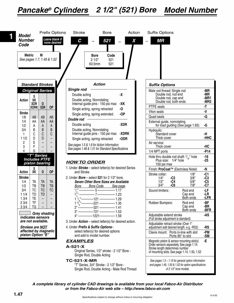
1
Pancake® Cylinders
Specifications subject to change without notice or incurring obligation
ModelNumberCode
Bore Stroke Action
–C –521 –X MRLeave blank if none desired
Metric MSee pages 1.7, 1.49 & 1.52
Bore Code 2 1/2" 521 63.5mm 521
Model Number2 1/2" (521) Bore
1.47
A complete library of cylinder CAD drawings is available from your local Fabco-Air Distributor or from the Fabco-Air web site – http://www.fabco-air.com
6-3-02
HOW TO ORDER1. Under Stroke – select letter(s) for desired Series and Stroke.
2. Under Bore – select 521 for 2 1/2" bore. Seven Other Bore Sizes are Available Bore Bore Code See page 1/2" --------------- 5 ----------------- 1.17 3/4" --------------- 7 ----------------- 1.23 1 1/8" ------------121 --------------- 1.29 1 5/8" ------------221 --------------- 1.35 2" ---------------321 --------------- 1.41 3" ---------------721 --------------- 1.53 4" --------------1221 --------------- 1.59
3. Under Action – select letter(s) for desired action.
4. Under Prefix & Suffix Options– select letter(s) for desired options and add to model number.
EXAMPLESA-521-X Original Series, 1/2" stroke - 2 1/2" Bore - Single Rod, Double Acting
TC-521-X-MR
Action Single rod Double acting -X Double acting, Nonrotating -XK Single acting, spring retracted -O
-OP Double rod Double acting -XDR Double acting, Nonrotating
XDRK Single acting, spring retracted -ODR
See pages 1.5 & 1.6 for Action Information. See pages 1.48 & 1.51 for Standard Specifications
Grey shading indicates sensors are not available.
Strokes are NOT affected by magnetic piston Option “E”
Standard Strokes
Original Series
X Action XK XDR O XDRK ODR OP Stroke 1/8 AB AB AB 1/4 AA AA AA 1/2 A A A 3/4 B B B 1 C C C 1 1/2 D D –
3 F – – 4 G – –
“T” SeriesIncludes PTFE piston bearing
X Action XK O OP Stroke
See pages 1.3 – 1.15 for general option information and pages 1.49, 1.50 & 1.52 for option specifications
of 2 1/2" bore models.
Suffix Options
Male rod thread: Single rod -MR Double rod, rod end -MR Double rod, cap end -MR1 Double rod, both ends -MR2
-T -V
Quad seals -Q
for load guiding (See page 1.65) -GHydraulic: Standard cover -H
-HHCAir service:
-HC -P14
Hole thru double rod shaft: 5/32" hole -16 -25
Finish: ProCoat™ -NStroke collar: 1/8" -C1 1/4" -C2 3/8" -C3 1/2" -C4 5/8" -C5 3/4" -C6 7/8" -C7Sound limiters: Rod end -LF Cap end -LR Both ends -LFRRubber Bumpers: Rod end -BF Cap end -BR Both ends -BFR
-AS (Full stroke adjustment is standard)Adjustable retract stroke (Over 1" adjustment add desired length, e.g. -RS2) -RSClevis mount: Ports in-line with slot -PM Ports 90° to slot -SMMagnetic piston & sensor mounting slot(s) -EOrder sensors separately. See page 1.14. Stroke length determines number of mounting slots. See page 1.14, 1.50, 1.52

1
Specifications subject to change without notice or incurring obligation
Pancake® Cylinders
1.48
Standard Specifications2-1/2" (521) BoreSingle Rod
2-14-08
1/2-20 x E1Female Rod Thread
3.25 Bolt Circle .27 Dia. Thru.38 C'Bore x .26 Dp.for 4, 1/4" SHCSequally spaced
3.745/8 x .11Wrench Flat
.75 Rod Dia.45°
.14
B1 K1
1/8 NPTStrokes AB & AA are Ported on Opposite Sides
Rod End Face
Y1Z1
Cap End Face
.19
1/2-20 x E2Female Rod Thread
3.25 Bolt Circle .27 Dia. Thru.38 C'Bore x .26 Dp.for 4, 1/4" SHCSequally spaced
3.745/8 x .11Wrench FlatRandomRotation
.75 Rod Dia.45°
.14
B2 K2
1/8 NPTStrokes AB & AA are Ported on Opposite Sides
Rod End Face
Y2Z2
Cap End Face
.38
RodRotationTolerance 1°
1/2-20 x E3Female Rod Thread
3.25 Bolt Circle .27 Dia. Thru.38 C'Bore x .26 Dp.for 4, 1/4" SHCSequally spaced
3.745/8 x .11Wrench Flat
.75 Rod Dia.
45°.14
B3 K3
1/8 NPT
Rod End Face
Y3Z3
Cap End Face
.19
.71 Rod End VentStrokes AB-C & TA - TCRod End VentStrokes D & TD
1/2-20 x E4Female Rod Thread
3.25 Bolt Circle .27 Dia. Thru.38 C'Bore x .26 Dp.for 4, 1/4" SHCSequally spaced
3.745/8 x .11Wrench Flat
.75 Rod Dia.
45°
.14 + Stroke
B4 K4
1/8 NPTStrokes AB & AA are Ported on Opposite Sides
Rod End Face
Y4Z4
Cap End Face
.63
Action –XDouble Acting
Action –XKDouble ActingNonrotating
See page 1.16 forMounting Bolts.
Seal Kits for Series:
See page 1.16 forMounting Bolts.
Seal Kits for Series:
Action –OPSingle ActingSpring Extended
See page 1.16 forMounting Bolts.
See Chart for SpringForces: Preload
Seal Kits for Series:
Action –OSingle ActingSpring Retracted
See page 1.16 forMounting Bolts.
See Chart for SpringForces: Preload
Seal Kits for Series:
Action –X Double Acting
Original Series "T" Series
Action –OP Single Acting, Spring Extended
Action –O Single Acting, Spring Retracted
Action –XK Double Acting, Nonrotating
Action –X Double Acting
Rod End Face VentRod End Face Vent
Stroke, Inches 1/8 1/4 1/2 3/4 1 1 1/2 2 3 4 1/4 1/2 3/4 1 1/4 1 3/4 2 3/4 3 3/4
B1 1.45 1.58 1.83 2.20 2.33 2.83 3.33 4.33 5.33 1.83 2.20 2.33 2.83 3.33 4.33 5.33
K1 1.05 1.18 1.43 1.80 1.93 2.43 2.93 3.93 4.93 1.43 1.80 1.93 2.43 2.93 3.93 4.93 Y1 .52 .52 .52 .64 .64 .64 .64 .64 .64 .52 .64 .64 .64 .64 .64 .64
Weight, lb. 1.43 1.50 1.67 2.00 2.03 2.38 2.73 3.46 4.19 1.89 2.22 2.25 2.60 2.95 3.68 4.41
B2 1.64 1.77 2.02 2.39 2.52 3.02 3.52 4.52 5.52 2.02 2.39 2.52 3.02 3.52 4.52 5.52
K2 1.24 1.37 1.62 1.99 2.12 2.62 3.12 4.12 5.12 1.62 1.99 2.12 2.62 3.12 4.12 5.12 Y2 .52 .52 .52 .64 .64 .64 .64 .64 .64 .52 .64 .64 .64 .64 .64 .64
Weight, lb. 1.64 1.72 1.89 2.23 2.27 2.63 3.00 3.75 4.51 2.11 2.45 2.50 2.85 3.22 4.00 4.73 B3 1.45 1.58 1.83 2.20 2.33 4.33 NA* NA* NA* 1.83 2.20 2.33 4.33 NA* NA* NA*
K3 1.05 1.13 1.43 1.80 1.93 3.93 NA* NA* NA* 1.43 1.80 1.93 3.93 NA* NA* NA* Y3 .64 NA* NA* NA* .64 NA* NA* NA*
Weight,. lb. 1.38 1.46 1.62 1.94 1.96 3.60 NA* NA* NA* 1.84 2.16 2.18 3.82 NA* NA* NA* Preload, lb. 12.0 6.2 7.0 5.0 4.7 7.3 NA* NA* NA* 13.1 10.6 8.0 9.5 NA* NA* NA* End of Stroke, lb. 18.0 18.0 20.0 15.5 20.0 20.0 NA* NA* NA* 20.0 15.5 20.0 20.0 NA* NA* NA* B4 2.02 2.27 2.77 3.39 3.77 NA* NA* NA* NA* 2.52 3.14 3.52 NA* NA* NA* NA*
K4 1.49 1.62 1.87 2.24 2.37 NA* NA* NA* NA* 1.87 2.24 2.37 NA* NA* NA* NA* Y4 .65 .77 1.02 1.40 1.64 NA* NA* NA* NA* .77 1.14 1.39 NA* NA* NA* NA*
Weight, lb. 1.91 1.98 2.16 2.49 2.51 NA* NA* NA* NA* 2.38 2.71 2.73 NA* NA* NA* NA*Preload, lb. 6.2 2.5 5.5 5.0 5.2 NA* NA* NA* NA* 11.2 12.4 10.2 NA* NA* NA* NA*End of Stroke, lb. 12.0 12.0 18.5 15.5 20.5 NA* NA* NA* NA* 18.5 21.1 22.6 NA* NA* NA* NA*
Action –XK Double Acting, Nonrotating
Action –O Single Acting, Spring Retracted
Action –OP Single Acting, Spring Extended

1
Pancake® Cylinders
Specifications subject to change without notice or incurring obligation1.49
Option Specifications2-1/2" (521) BoreAlso See Page 1.48
12-15-04
Prefix Option -M Metric Cylinder & Rod Thread 63.5mm Bore
Also see Option Information on page 1.7.82.5mm Bolt Circle
G1/8 Ports with 14mm Spotface
M12 x 25.4
Standard Female Rod Thread M12.Male Rod ThreadOption -MR shown.
Mounting Holes6.7mm Diameter Thru10.3mm C'Bore x 6.4mm Dp.4 Places for M6 SHCS
Thread PitchesM6 = 1.0mmM12 = 1.75mm
Conversion FactorInches x 25.4 = mm
Suffix Options charted on the right are available on Original -
mensional changes from the Standard Specifications on page 1.48. – Also see Option Information on pages 1.7 thru 1.15.
-X -XK NA NA NA -O NA NA NA NA NA NA -OP NA NA NA
Suffix Options -PM & -SM Clevis Mount
with Actions: -X, -XK, -O, -OPAlso see Option Information on page 1.13.
EM-521 Eye Bracket KitMates with Clevis Mount shown above.Order separately.
EM-121 Eye Bracket KitMates with any Rod Clevis shown above.Order separately.
.50
.97
1.63
Oil filled bushings
Chart
.90
.50 1.86
-PMPort LocationIN LINE with Slot -SM
Port Location90° to Slot
Also see page 1.48
Note 1
ChartAction Dimension-X, -O, -OP 1.19 + B -XK 1.00 + B
Note 1:Hole Diameter = .501Pin Diameter = .500Pin (416 Stainless Steel)and Clips are included.
.751.13
2.25
.38
2.00
2.001.38
Hole .501Oil filled bushingis standard
.47
1.38 1.50.33 Dia. 4 Placesfor Flat Head Screws
FHSCS are included
Material:
.44.69
1.38
.25
1.50
1.501.13
Hole .3135Oil filled bushingis standard
.30
1.13 .94.27 Dia. 4 Placesfor Flat Head Screws
are included
Material:
RC-Chart Rod Clevis and Pin
in the Pancake® Cylinders.
shown below.
.32
Pin Diameter .3125
1.691.31
1.21 .63 . 61
1.00
Materials:
Stud – SteelPin – 416 Stainless SteelPin & Clips are included
Rod Clevis NumberRC-54RC-56
MRC-54MRC-56
Strokes
ABAA–GMAB
MAA–MG
.39"
.62"9.9mm
15.7mm
Stroke mm 3.2 6.4 12.7 19.1 25.4 38.1 50.8 76.2 101.6
Stroke mm 6.4 12.7 19.1 31.8 44.5 69.9 95.3
Original Series
“T” Series

1
Specifications subject to change without notice or incurring obligation
Pancake® Cylinders
45°
90°90°
#1#2
Sensors available for “AA” & “TA” strokes and longer. Stroke AA is ported on opposite sides.
1.50
Option Specifications2-1/2" (521) BoreAlso See Page 1.48
Suffix Option -RS Adjustable Retract Stroke
with Actions: -X, -XK, -O, -OPAlso see Option Information on page 1.11.
Suffix Option -HHC Hydraulic & -HC Air
Also see Option Information on page 1.9 for Pressureand Mounting details.
Suffix Option -MR Male Rod ThreadAvailable on Original
Actions: -X, -XK, -O, -OP.Also see Option Information on page 1.8.
.19
.19 + B(-XK only use B2 as shown on page 1.48. No additional length is required.)(-OP Only use B4 as shown on page 1.48.No additional length is required.)
.050 Stroke AdjustmentPer Revolution
Adjusting Screw
Standard Adjustment is 1"
1/2-20 x 1.00.19 + B.19 + K
.38
2-5-08
2 1/2" (521) BoreQuick Reference to Standard Strokes
Use the appropriate Stroke Letter in the Model Number
Available on Original Series
Action Stroke X, XK
1/4 -----------------AA 1/2 ------------------A 3/4 ------------------B 1 -------------------- C 1 1/2 --------------- D 2 --------------------- 3 ---------------------F 4 -------------------- G
Available on“T” Series
Action Stroke X, XK
1/4 ----------------- 1/2 ----------------- 3/4 -----------------
1 1/4 -------------- 1 3/4 -------------- 2 3/4 -------------- 3 3/4 -------------
Suffix Option -E Specifies Magnetic Piston and Dovetail Mounting Slot(s)Strokes are NOT affected by magnetic piston.
– Sensors Must be Ordered SeparatelySee Sensor Models Available page 1.14
Suffix Option -AS Adjustable Extend StrokeAvailable on Original Series with Actions: -X, -XK, -OAlso see Option Information on page 1.11.
BB C
D
2.00 Dia.
1.50 Dia.
.063 Stroke AdjustmentPer Revolution
Stroke Inches 1/8 1/4 1/2 3/4 1 1-1/2 2 3 4
Actions: -X, -XK BB 2.02 2.14 2.39 2.77 2.89 3.39 3.89 4.89 5.89Actions:-O BB 2.02 2.14 2.39 2.77 2.89 4.89 NA NA NA C 1.67 1.91 2.41 2.91 3.41 4.41 5.41 7.41 9.41 D 0.63 0.75 1.00 1.25 1.50 2.00 2.50 3.50 4.50
Sensor Slots atPositions #1 and # 2
Sensor Slot atPosition #1 only
1/4" 60° Dovetail Profile of Sensor & Mounting Slot.

1
Pancake® Cylinders
Specifications subject to change without notice or incurring obligation1.51 4-22-04
Standard Specifications2-1/2" (521) BoreDouble Rod
Action –XDR Original SeriesDouble Rod, Double Acting
Stroke, Inches 1/8 1/4 1/2 3/4 1 1-1/2 2 3 4
B 2.02 2.14 2.39 2.77 2.89 3.39 3.89 4.89 5.89
K 1.63 1.75 2.00 2.38 2.50 3.00 3.50 4.50 5.50 Y .52 .52 .52 .64 .64 .64 .64 .64 .64
Weight, lb. 2.20 2.29 2.48 2.82 2.83 3.28 3.67 4.60 5.40
Action –XDRK Original SeriesDouble Rod, Double Acting, Nonrotating
Action –ODR Original SeriesDouble Rod, Single Acting, Spring Retracted
Stroke, Inches 1/8 1/4 1/2 3/4 1 1-1/2 2 3 4
B 2.02 2.14 2.39 2.77 2.89 3.39 3.89 4.89 5.89
K 1.63 1.75 2.00 2.38 2.50 3.00 3.50 4.50 5.50 Y .52 .52 .52 .64 .64 .64 .64 .64 .64
Weight, lb. 2.34 2.43 2.63 2.97 2.99 3.45 3.85 4.79 5.62
1/2-20 x EFemale Rod Thread
3.25 Bolt Circle .27 Dia. Thru.38 C'Bore x .26 Dp.for 4, 1/4" SHCSequally spaced
3.745/8 x .11Wrench Flat
.75 Rod Dia.45°
.14
B K
1/8 NPT
Rod End Face
YZ
Cap End Face
.75
.14 + Stroke
.71 Rod End VentStrokes AB – C
Rod End VentStroke D
1/2-20 x EFemale Rod Thread
3.25 Bolt Circle .27 Dia. Thru.38 C'Bore x .26 Dp.for 4, 1/4" SHCSequally spaced
3.745/8 x .11Wrench Flat
.75 Rod Dia.45°
.14
B K
1/8 NPTStrokes AB & AA are Ported on Opposite Sides
Rod End Face
YZ
Cap End Face
.75
.14 + Stroke
1/2-20 x EFemale Rod Thread
3.25 Bolt Circle .27 Dia. Thru.38 C'Bore x .26 Dp.for 4, 1/4" SHCSequally spaced
3.745/8 x .11Wrench FlatRandomRotation
.75 Rod Dia.45°
.14
B K
1/8 NPTStrokes AB & AA are Ported on Opposite Sides
Rod End Face
YZ
Cap End Face
.75
.14 + Stroke
RodRotationTolerance 1°
Stroke, Inches 1/8 1/4 1/2 3/4 1 1-1/2
B 2.02 2.14 2.39 2.77 2.89 4.89
K 1.63 1.75 2.00 2.38 2.50 4.50 Y .64
Weight, lb. 2.14 2.23 2.41 2.76 2.77 4.52Spring Return Forces, lb.Preload 12.0 6.3 7.0 5.0 4.8 7.3
See page 1.16 forMounting Bolts
See page 1.16 forMounting Bolts
See page 1.16 forMounting Bolts

1
Specifications subject to change without notice or incurring obligation
Pancake® Cylinders
45°
90°90°
#1#2
Sensors available for “AA”strokes and longer. Stroke AA is ported on opposite sides.
Sensor Slots atPositions #1 and # 2
Sensor Slot atPosition #1 only
1.52
Option Specifications2-1/2" (521) BoreAlso See Page 1.51
2-5-08
Suffix Options charted on the right are available on Original Series with the Actions indicated (dimensional changes from the Standard Specifications on page 1.51. – Also see Option Information on pages 1.7 thru 1.15.
-XDR - XDRK NA NA NA -ODR NA NA NA NA NA NA
Prefix Option -M Metric Cylinder & Rod Thread, 63.5mm BoreAvailable on Original Series with Actions: -XDR, -XDRK, -ODRAlso see Option Information on page 1.7.
82.5mm Bolt Circle
G1/8 Ports with 14mm Spotface
M12 x 25.4
Standard Female Rod Thread M12.Male Rod ThreadOption -MR shown.
Mounting Holes6.7mm Diameter Thru10.3mm C'Bore x 6.4mm Dp.4 Places for M6 SHCS
Thread PitchesM6 = 1.0mmM12 = 1.75mm
Conversion FactorInches x 25.4 = mm
Stroke mm 3.2 6.4 12.7 19.1 25.4 38.1 50.8 76.2 101.6
Suffix Options -MR, -MR1, -MR2 Male Rod Thread
Available on Original Series with Actions -XDR, -XDRK, -ODR.
–MR–MR1–MR2
Also see Option Information on Page 1.8.
1/2-20 x 1.00
2 1/2" (521) Bore Quick Reference to Standard StrokesUse the appropriate Stroke Letter in the Model Number
Suffix Option -E Specifies Magnetic Piston and Dovetail Mounting Slot(s)Strokes are NOT affected by magnetic piston.
Available on Original Series
Action Stroke XDR, XDRK
1/4 -----------------AA 1/2 ------------------A 3/4 ------------------B 1 -------------------- C 1 1/2 --------------- D 2 --------------------- 3 ---------------------F 4 -------------------- G
– Sensors Must be Ordered SeparatelySee Sensor Models Available page 1.14
1/4" 60° Dovetail Profile of Sensor & Mounting Slot.

1
Pancake® Cylinders
Specifications subject to change without notice or incurring obligation
ModelNumberCode
Stroke Action
–C –721 – MRLeave blank if none desired
Bore Code 3" 721 76.2mm 721
Metric MSee pages 1.7, 1.55 & 1.58
X
Model Number3" (721) Bore
HOW TO ORDER1. Under Stroke – select letter(s) for desired Series and Stroke.2. Under Bore – select 721 for 3" bore.
Seven Other Bore Sizes are Available Bore Bore Code See page 1/2" --------------- 5 ----------------- 1.17 3/4" --------------- 7 ----------------- 1.23 1 1/8" ------------121 --------------- 1.29 1 5/8" ------------221 --------------- 1.35 2" ---------------321 --------------- 1.41 2 1/2" ------------521 --------------- 1.47 4" --------------1221 --------------- 1.59
3. Under Action – select letter(s) for desired action.
4. Under Prefix & Suffix Options– select letter(s) for desired options and add to model number.
EXAMPLESA-721-X Original Series, 1/2" stroke - 3" Bore - Single Rod, Double Acting
TC-721-X-MR
1.53
A complete library of cylinder CAD drawings is available from your local Fabco-Air Distributor or from the Fabco-Air web site – http://www.fabco-air.com
6-3-02
Action Single rod Double acting -X Double acting, Nonrotating -XK Single acting, spring retracted -O
-OP Double rod Double acting -XDR Double acting, Nonrotating
XDRK Single acting, spring retracted -ODR
See pages 1.5 & 1.6 for Action Information. See pages 1.54 & 1.57 for Standard Specifications
Grey shading indicates sensors are not available.
Strokes are NOT affected by magnetic piston Option “E”
Standard Strokes
Original Series X Action XK XDR O XDRK ODR OP Stroke 1/8 AB AB AB 1/4 AA AA AA 1/2 A A A 3/4 B B B 1 C C C 1 1/2 D D –
3 F – – 4 G – –
“T” SeriesIncludes PTFE piston bearing
X Action XK O OP Stroke
See pages 1.3 – 1.15 for general option informa-tion and pages 1.55 , 1.56 & 1.58 for option
specifications of 3" bore models.
Suffix Options
Male rod thread: Single rod -MR Double rod, rod end -MR Double rod, cap end -MR1 Double rod, both ends -MR2
-T -V
Quad seals -Q -G
for load guiding (See page 1.65)Hydraulic: Standard cover -H
-HHCAir service:
-HC -P14
Hole thru double rod shaft: 5/32" hole -161/4" hole -25
Finish: ProCoat™ -N
Stroke collar: 1/8" -C1 1/4" -C2 3/8" -C3 1/2" -C4 5/8" -C5 3/4" -C6 7/8" -C7Sound limiters: Rod end -LF Cap end -LR Both ends -LFRRubber Bumpers: Rod end -BF Cap end -BR Both ends -BFR
-AS (Full stroke adjustment is standard)Adjustable retract stroke (Over 1" adjustment add desired length, e.g. -RS2) -RSClevis mount: Ports in-line with slot -PM Ports 90° to slot -SMMagnetic piston & sensor mounting slot(s) -EOrder sensors separately. See page 1.14.Stroke length determines number of mounting slots. See page 1.14, 1.56, 1.58
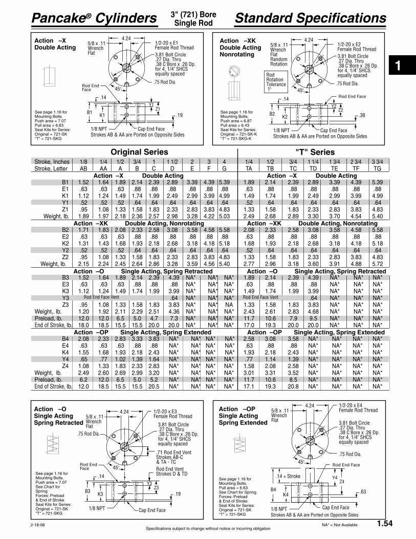
1
Specifications subject to change without notice or incurring obligation
Pancake® Cylinders
1.54
Standard Specifications3" (721) BoreSingle Rod
2-18-08
Action –XDouble Acting
Action –XKDouble ActingNonrotating
See page 1.16 forMounting Bolts.
Seal Kits for Series:
See page 1.16 forMounting Bolts.
Seal Kits for Series:
Action –OPSingle ActingSpring Extended
See page 1.16 forMounting Bolts.
See Chart for SpringForces: Preload
Seal Kits for Series:
Action –OSingle ActingSpring Retracted
See page 1.16 forMounting Bolts.
See Chart for SpringForces: Preload
Seal Kits for Series:
Original Series "T" Series
Action –OP Single Acting, Spring Extended
Action –O Single Acting, Spring Retracted
Action –XK Double Acting, Nonrotating
Action –X Double Acting
Rod End Face VentRod End Face Vent
Stroke, Inches 1/8 1/4 1/2 3/4 1 1 1/2 2 3 4 1/4 1/2 3/4 1 1/4 1 3/4 2 3/4 3 3/4
B1 1.52 1.64 1.89 2.14 2.39 2.89 3.39 4.39 5.39 1.89 2.14 2.39 2.89 3.39 4.39 5.39
K1 1.12 1.24 1.49 1.74 1.99 2.49 2.99 3.99 4.99 1.49 1.74 1.99 2.49 2.99 3.99 4.99 Y1 .52 .52 .52 .64 .64 .64 .64 .64 .64 .52 .64 .64 .64 .64 .64 .64
Weight, lb. 1.89 1.97 2.18 2.36 2.57 2.98 3.28 4.22 5.03 2.49 2.68 2.89 3.30 3.70 4.54 5.40
B2 1.71 1.83 2.08 2.33 2.58 3.08 3.58 4.58 5.58 2.08 2.33 2.58 3.08 3.58 4.58 5.58
K2 1.31 1.43 1.68 1.93 2.18 2.68 3.18 4.18 5.18 1.68 1.93 2.18 2.68 3.18 4.18 5.18 Y2 .52 .52 .52 .64 .64 .64 .64 .64 .64 .52 .64 .64 .64 .64 .64 .64
Weight, lb. 2.15 2.24 2.45 2.64 2.86 3.28 3.59 4.56 5.40 2.77 2.96 3.18 3.60 3.91 4.88 5.72
B3 1.52 1.64 1.89 2.14 2.39 4.39 NA* NA* NA* 1.89 2.14 2.39 4.39 NA* NA* NA*
K3 1.12 1.24 1.49 1.74 1.99 3.99 NA* NA* NA* 1.49 1.74 1.99 3.99 NA* NA* NA* Y3 .64 NA* NA* NA* .64 NA* NA* NA*
Weight,. lb. 1.20 1.92 2.11 2.29 2.51 4.36 NA* NA* NA* 2.43 2.61 2.83 4.68 NA* NA* NA* Preload, lb. 12.0 12.0 6.5 5.0 4.7 7.3 NA* NA* NA* 11.7 10.6 7.9 9.5 NA* NA* NA* End of Stroke, lb. 18.0 18.5 15.5 15.5 20.0 20.0 NA* NA* NA* 17.0 19.3 20.0 20.0 NA* NA* NA*
B4 2.08 2.33 2.83 3.33 3.83 NA* NA* NA* NA* 2.58 3.08 3.58 NA* NA* NA* NA*
K4 1.55 1.68 1.93 2.18 2.43 NA* NA* NA* NA* 1.93 2.18 2.43 NA* NA* NA* NA* Y4 .65 .77 1.02 1.39 1.64 NA* NA* NA* NA* .77 1.14 1.39 NA* NA* NA* NA*
Weight, lb. 2.49 2.60 2.69 2.99 3.20 NA* NA* NA* NA* 3.01 3.31 3.52 NA* NA* NA* NA*Preload, lb. 6.2 12.0 6.5 5.0 5.2 NA* NA* NA* NA* 11.7 10.6 8.5 NA* NA* NA* NA*End of Stroke, lb. 12.0 18.5 15.5 15.5 20.5 NA* NA* NA* NA* 17.1 19.3 20.8 NA* NA* NA* NA*
1/2-20 x E4Female Rod Thread
3.81 Bolt Circle .27 Dia. Thru.38 C'Bore x .26 Dp.for 4, 1/4" SHCSequally spaced
4.245/8 x .11Wrench Flat
.75 Rod Dia.45°
.14 + Stroke
B4K4
1/8 NPTStrokes AB & AA are Ported on Opposite Sides
Rod End Face
Y4Z4
Cap End Face
.63
1/2-20 x E3Female Rod Thread
3.81 Bolt Circle .27 Dia. Thru.38 C'Bore x .26 Dp.for 4, 1/4" SHCSequally spaced
4.245/8 x .11Wrench Flat
.75 Rod Dia.
45°
.14
B3 K3
1/8 NPT
Rod End Face
Y3Z3
Cap End Face
.19
.71 Rod End VentStrokes AB-C & TA - TCRod End VentStrokes D & TD
1/2-20 x E1Female Rod Thread3.81 Bolt Circle .27 Dia. Thru.38 C'Bore x .26 Dp.for 4, 1/4" SHCSequally spaced
4.245/8 x .11Wrench Flat
.75 Rod Dia.45°
.14
B1 K1
1/8 NPTStrokes AB & AA are Ported on Opposite Sides
Rod End Face
Y1Z1
Cap End Face
.19
1/2-20 x E2Female Rod Thread3.81 Bolt Circle .27 Dia. Thru.38 C'Bore x .26 Dp.for 4, 1/4" SHCSequally spaced
4.245/8 x .11Wrench FlatRandomRotation
.75 Rod Dia.45°
.14
B2 K2
1/8 NPTStrokes AB & AA are Ported on Opposite Sides
Rod End Face
Y2Z2
Cap End Face
.38
RodRotationTolerance 1°
Action –OP Single Acting, Spring Extended
Action –O Single Acting, Spring Retracted
Action –XK Double Acting, Nonrotating
Action –X Double Acting
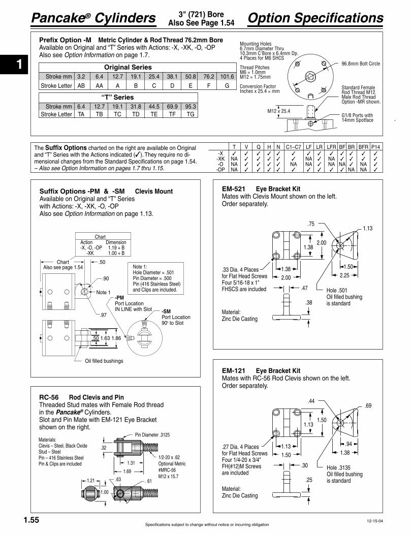
1
Pancake® Cylinders
Specifications subject to change without notice or incurring obligation1.55 12-15-04
Option Specifications3" (721) BoreAlso See Page 1.54
.50
.97
1.63
Oil filled bushings
Chart
.90
.50 1.86
-PMPort LocationIN LINE with Slot -SM
Port Location90° to Slot
Also see page 1.54
Note 1
Note 1:Hole Diameter = .501Pin Diameter = .500Pin (416 Stainless Steel)and Clips are included.
ChartAction Dimension-X, -O, -OP 1.19 + B -XK 1.00 + B
Suffix Options -PM & -SM Clevis Mount
with Actions: -X, -XK, -O, -OPAlso see Option Information on page 1.13.
EM-521 Eye Bracket KitMates with Clevis Mount shown on the left.Order separately.
RC-56 Rod Clevis and Pin
in the Pancake® Cylinders.
shown on the right.
EM-121 Eye Bracket KitMates with RC-56 Rod Clevis shown on the left.Order separately.
Prefix Option -M Metric Cylinder & Rod Thread 76.2mm Bore
Also see Option Information on page 1.7.
Suffix Options charted on the right are available on Original -
mensional changes from the Standard Specifications on page 1.54. – Also see Option Information on pages 1.7 thru 1.15.
-X -XK NA NA NA -O NA NA NA NA NA NA -OP NA NA NA
96.8mm Bolt Circle
G1/8 Ports with 14mm Spotface
M12 x 25.4
Standard Female Rod Thread M12. Male Rod ThreadOption -MR shown.
Mounting Holes6.7mm Diameter Thru10.3mm C'Bore x 6.4mm Dp.4 Places for M6 SHCS
Thread PitchesM6 = 1.0mmM12 = 1.75mm
Conversion FactorInches x 25.4 = mm
Stroke mm 3.2 6.4 12.7 19.1 25.4 38.1 50.8 76.2 101.6
Stroke mm 6.4 12.7 19.1 31.8 44.5 69.9 95.3
Original Series
.751.13
2.25
.38
2.00
2.001.38
Hole .501Oil filled bushingis standard
.47
1.38 1.50.33 Dia. 4 Placesfor Flat Head Screws
FHSCS are included
Material:
.44.69
1.38
.25
1.50
1.501.13
Hole .3135Oil filled bushingis standard
.30
1.13 .94.27 Dia. 4 Placesfor Flat Head Screws
are included
Material:
.32
Pin Diameter .3125
Optional Metric1.69
1.31
1.21 .63 . 61
1.00
Materials:
Stud – SteelPin – 416 Stainless SteelPin & Clips are included
“T” Series

1
Specifications subject to change without notice or incurring obligation
Pancake® Cylinders
45°
30°30°#1#2
Sensors available for “AA” & “TA” strokes and longer. Stroke AA is ported on opposite sides.
Sensor Slots atPositions #1 and # 2
Sensor Slot atPosition #1 only
1.56
Option Specifications3" (721) BoreAlso See Page 1.54
2-5-08
3" (721) BoreQuick Reference to Standard Strokes
Use the appropriate Stroke Letter in the Model Number
Suffix Option -E Specifies Magnetic Piston and Dovetail Mounting Slot(s)Strokes are NOT affected by magnetic piston.
Available on Original Series
Action Stroke X, XK
1/4 ------------------AA 1/2 -------------------A 3/4 -------------------B 1 --------------------- C 1 1/2 ---------------- D 2 ---------------------- 3 ----------------------F 4 --------------------- G
Available on“T” Series
Action Stroke X, XK
1/4 ----------------- 1/2 ----------------- 3/4 -----------------
1 1/4 -------------- 1 3/4 -------------- 2 3/4 -------------- 3 3/4 -------------
– Sensors Must be Ordered SeparatelySee Sensor Models Available page 1.14
Suffix Option -RS Adjustable Retract Stroke
with Actions: -X, -XK, -O, -OPAlso see Option Information on page 1.11.
Suffix Option -HHC Hydraulic & -HC Air
Also see Option Information on page 1.9 for Pressureand Mounting details.
Suffix Option -MR Male Rod ThreadAvailable on Original
Actions: -X, -XK, -O, -OP.Also see Option Information on page 1.8.
.19
.19 + B(-XK Only use B2 as shown on page 1.54. No additional length is required.)(-OP Only use B4 as shown on page 1.54. No additional length is required.)
.050 Stroke AdjustmentPer Revolution
Adjusting Screw
Standard Adjustment is 1"
1/2-20 x 1.00.19 + B.19 + K
.38
Suffix Option -AS Adjustable Extend StrokeAvailable on Original Series with Actions: -X, -XK, -OAlso see Option Information on page 1.11.
BB C
D
2.00 Dia.
1.50 Dia.
.063 Stroke AdjustmentPer Revolution
Stroke Inches 1/8 1/4 1/2 3/4 1 1-1/2 2 3 4
Actions: -X, -XK BB 2.08 2.20 2.45 2.70 2.95 3.45 3.95 4.95 5.95Actions:-O BB 2.08 2.20 2.45 2.70 2.95 4.95 NA NA NA C 1.67 1.91 2.41 2.91 3.41 4.41 5.41 7.41 9.41 D 0.63 0.75 1.00 1.25 1.50 2.00 2.50 3.50 4.50
1/4" 60° Dovetail Profile of Sensor & Mounting Slot.
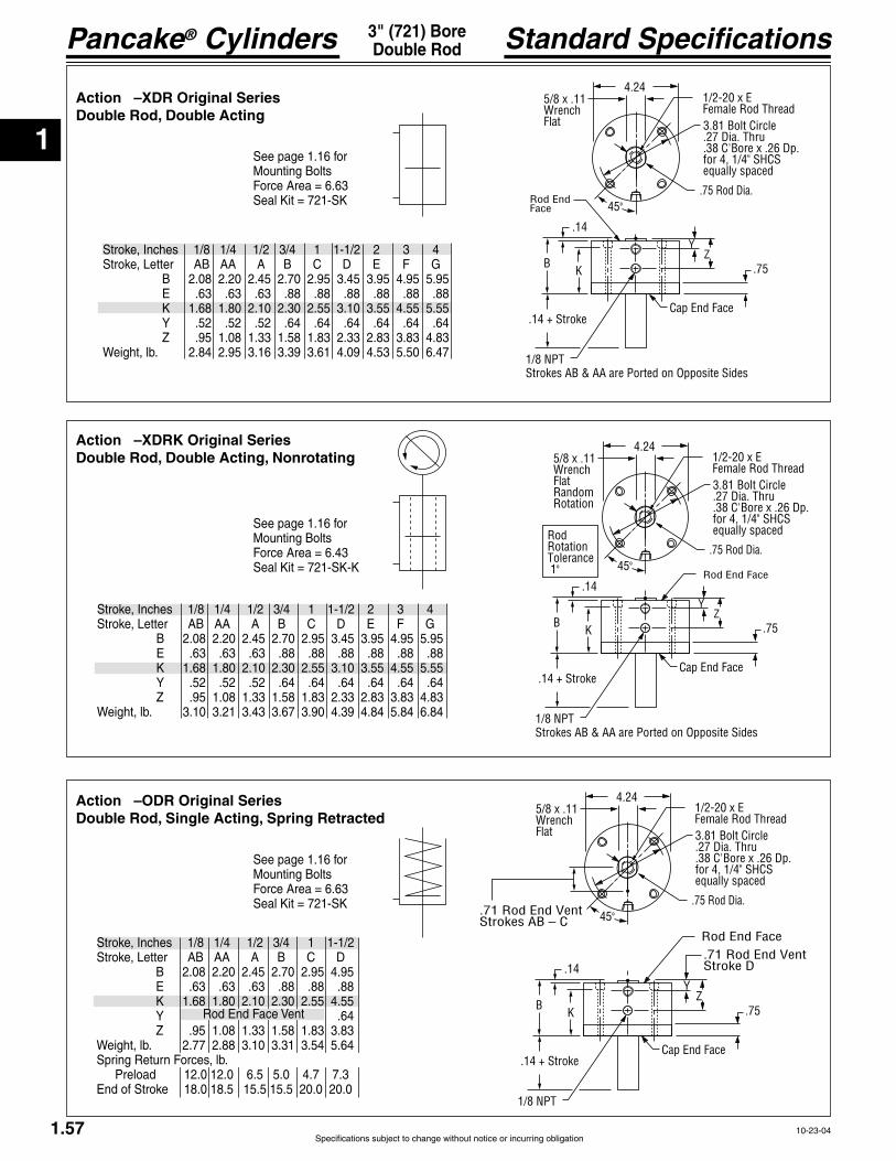
1
Pancake® Cylinders
Specifications subject to change without notice or incurring obligation1.57
Standard Specifications3" (721) BoreDouble Rod
10-23-04
1/2-20 x EFemale Rod Thread3.81 Bolt Circle .27 Dia. Thru.38 C'Bore x .26 Dp.for 4, 1/4" SHCSequally spaced
4.245/8 x .11Wrench Flat
.75 Rod Dia.45°
.14
BK
1/8 NPTStrokes AB & AA are Ported on Opposite Sides
Rod End Face
YZ
Cap End Face
.75
.14 + Stroke
1/2-20 x EFemale Rod Thread3.81 Bolt Circle .27 Dia. Thru.38 C'Bore x .26 Dp.for 4, 1/4" SHCSequally spaced
4.245/8 x .11Wrench FlatRandomRotation
.75 Rod Dia.45°
.14
BK
1/8 NPTStrokes AB & AA are Ported on Opposite Sides
Rod End Face
YZ
Cap End Face
.75
.14 + Stroke
RodRotationTolerance 1°
1/2-20 x EFemale Rod Thread3.81 Bolt Circle .27 Dia. Thru.38 C'Bore x .26 Dp.for 4, 1/4" SHCSequally spaced
4.245/8 x .11Wrench Flat
.75 Rod Dia.45°
.14
BK
1/8 NPT
Rod End Face
YZ
Cap End Face
.75
.14 + Stroke
.71 Rod End VentStrokes AB – C
.71 Rod End VentStroke D
Action –XDR Original SeriesDouble Rod, Double Acting
Stroke, Inches 1/8 1/4 1/2 3/4 1 1-1/2 2 3 4
B 2.08 2.20 2.45 2.70 2.95 3.45 3.95 4.95 5.95
K 1.68 1.80 2.10 2.30 2.55 3.10 3.55 4.55 5.55 Y .52 .52 .52 .64 .64 .64 .64 .64 .64
Weight, lb. 2.84 2.95 3.16 3.39 3.61 4.09 4.53 5.50 6.47
Action –XDRK Original SeriesDouble Rod, Double Acting, Nonrotating
Action –ODR Original SeriesDouble Rod, Single Acting, Spring Retracted
Stroke, Inches 1/8 1/4 1/2 3/4 1 1-1/2
B 2.08 2.20 2.45 2.70 2.95 4.95
K 1.68 1.80 2.10 2.30 2.55 4.55 Y .64
Weight, lb. 2.77 2.88 3.10 3.31 3.54 5.64Spring Return Forces, lb. Preload 12.0 12.0 6.5 5.0 4.7 7.3
Stroke, Inches 1/8 1/4 1/2 3/4 1 1-1/2 2 3 4
B 2.08 2.20 2.45 2.70 2.95 3.45 3.95 4.95 5.95
K 1.68 1.80 2.10 2.30 2.55 3.10 3.55 4.55 5.55 Y .52 .52 .52 .64 .64 .64 .64 .64 .64
Weight, lb. 3.10 3.21 3.43 3.67 3.90 4.39 4.84 5.84 6.84
See page 1.16 forMounting Bolts
See page 1.16 forMounting Bolts
See page 1.16 forMounting Bolts
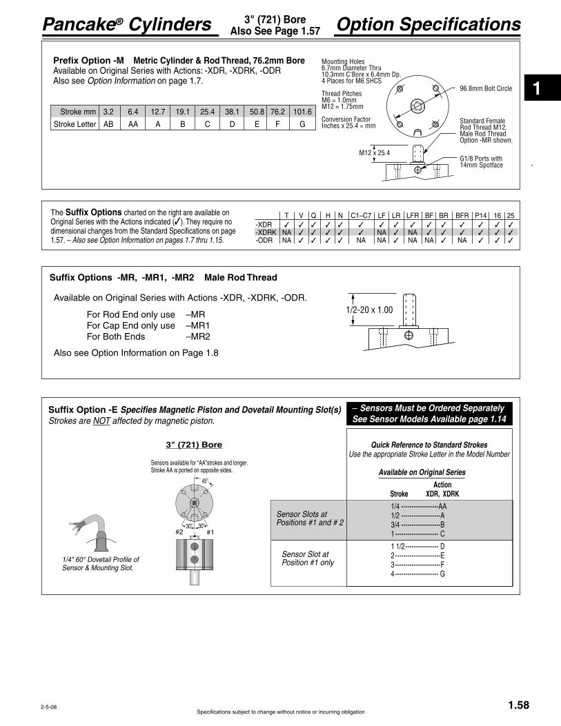
1
Specifications subject to change without notice or incurring obligation
Pancake® Cylinders
45°
30°30°#1#2
Sensors available for “AA”strokes and longer. Stroke AA is ported on opposite sides.
Sensor Slots atPositions #1 and # 2
Sensor Slot atPosition #1 only
1.58
Option Specifications3" (721) BoreAlso See Page 1.57
2-5-08
3" (721) Bore Quick Reference to Standard StrokesUse the appropriate Stroke Letter in the Model Number
Suffix Option -E Specifies Magnetic Piston and Dovetail Mounting Slot(s)Strokes are NOT affected by magnetic piston.
Available on Original Series
Action Stroke XDR, XDRK
1/4 ------------------AA 1/2 -------------------A 3/4 -------------------B 1 --------------------- C
1 1/2 ---------------- D 2 ---------------------- 3 ----------------------F 4 --------------------- G
– Sensors Must be Ordered SeparatelySee Sensor Models Available page 1.14
-XDR -XDRK NA NA NA -ODR NA NA NA NA NA NA
Suffix Options charted on the right are available on Original Series with the Actions indicated (dimensional changes from the Standard Specifications on page 1.57. – Also see Option Information on pages 1.7 thru 1.15.
Suffix Options -MR, -MR1, -MR2 Male Rod Thread
Available on Original Series with Actions -XDR, -XDRK, -ODR.
Also see Option Information on Page 1.8
1/2-20 x 1.00
Prefix Option -M Metric Cylinder & Rod Thread, 76.2mm BoreAvailable on Original Series with Actions: -XDR, -XDRK, -ODRAlso see Option Information on page 1.7.
96.8mm Bolt Circle
G1/8 Ports with 14mm Spotface
M12 x 25.4
Standard Female Rod Thread M12. Male Rod ThreadOption -MR shown.
Mounting Holes6.7mm Diameter Thru10.3mm C'Bore x 6.4mm Dp.4 Places for M6 SHCS
Thread PitchesM6 = 1.0mmM12 = 1.75mm
Conversion FactorInches x 25.4 = mm
Stroke mm 3.2 6.4 12.7 19.1 25.4 38.1 50.8 76.2 101.6
1/4" 60° Dovetail Profile of Sensor & Mounting Slot.
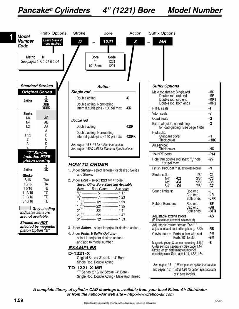
1
Pancake® Cylinders
Specifications subject to change without notice or incurring obligation
ModelNumberCode
Bore Stroke Action
–D –1221 – MRLeave blank if none desired
Metric MSee pages 1.7, 1.61 & 1.64
Bore Code 4" 1221 101.6mm 1221
X
Model Number4" (1221) Bore
HOW TO ORDER1. Under Stroke – select letter(s) for desired Series and Stroke.
2. Under Bore – select 1221 for 4" bore. Seven Other Bore Sizes are Available Bore Bore Code See page 1/2" --------------- 5 ----------------- 1.17 3/4" --------------- 7 ----------------- 1.23 1 1/8" ------------121 --------------- 1.29 1 5/8" ------------221 --------------- 1.35 2" ---------------321 --------------- 1.41 2 1/2" ------------521 --------------- 1.47 3" ---------------721 --------------- 1.53
3. Under Action – select letter(s) for desired action.
4. Under Prefix & Suffix Options– select letter(s) for desired options and add to model number.
EXAMPLESD-1221-X Original Series, 3" stroke - 4" Bore - Single Rod, Double Acting
TD-1221-X-MR
A complete library of cylinder CAD drawings is available from your local Fabco-Air Distributor or from the Fabco-Air web site – http://www.fabco-air.com
1.59 6-3-02
Action Single rod
Double acting -X
Double acting, Nonrotating -XK
Double rod
Double acting -XDR
Double acting, NonrotatingXDRK
See pages 1.5 & 1.6 for Action Information. See pages 1.60 & 1.63 for Standard Specifications
Grey shading indicates sensors are not available.
Strokes are NOT affected by magnetic piston Option “E”
Standard Strokes
Original Series X Action XK XDR XDRK Stroke 1/8 AC 1/4 AB 1/2 AA 1 A 1 1/2 B 2 C 3 D
“T” SeriesIncludes PTFE piston bearing
X Action XK Stroke
See pages 1.3 – 1.15 for general option information and pages 1.61, 1.62 & 1.64 for option specifications
of 4" bore models.
Suffix Options
Male rod thread: Single rod -MR Double rod, rod end -MR Double rod, cap end -MR1 Double rod, both ends -MR2
-T -V
Quad seals -Q -G
for load guiding (See page 1.65)Hydraulic: Standard cover -H
-HHCAir service:
-HC -P14
Hole thru double rod shaft: 1/4" hole -25 Finish: ProCoat™ -N
Stroke collar: 1/8" -C1 1/4" -C2 3/8" -C3 1/2" -C4 5/8" -C5 3/4" -C6 7/8" -C7Sound limiters: Rod end -LF Cap end -LR Both ends -LFRRubber Bumpers: Rod end -BF Cap end -BR Both ends -BFR
-AS (Full stroke adjustment is standard)Adjustable retract stroke (Over 1" adjustment add desired length, e.g. -RS2) -RSClevis mount: Ports in-line with slot -PM Ports 90° to slot -SMMagnetic piston & sensor mounting slot(s) -EOrder sensors separately. See page 1.14. Stroke length determines number of mounting slots. See page 1.14, 1.62, 1.64

1
Specifications subject to change without notice or incurring obligation
Pancake® Cylinders
1.60
Standard Specifications4" (1221) BoreSingle Rod
4-22-04
Stroke, Inches 1/8 1/4 1/2 1 1 1/2 2 3 4 5/16 13/16 1 5/16 1 13/16 2 13/16 3 13/16
B1 1.89 2.02 2.27 2.77 3.27 3.77 4.77 5.77 2.27 2.77 3.27 3.77 4.77 5.77
K1 1.43 1.56 1.81 2.31 2.81 3.31 4.31 5.31 1.81 2.31 2.81 3.31 4.31 5.31 Y1 .58 .58 .70 .70 .70 .70 .70 .70 .70 .70 .70 .70 .70 .70
Weight, lb. 3.88 4.01 4.34 4.91 5.63 6.22 7.53 8.84 5.04 5.61 6.33 6.92 8.23 9.54
B2 2.08 2.21 2.46 2.96 3.46 3.96 4.96 5.96 2.46 2.96 3.46 3.96 4.96 5.96
K2 1.62 1.75 2.00 2.50 3.00 3.50 4.50 5.50 2.00 2.50 3.00 3.50 4.50 5.50 Y2 .58 .58 .70 .70 .70 .70 .70 .70 .70 .70 .70 .70 .70 .70
Weight, lb. 4.31 4.44 4.78 5.36 6.10 6.70 8.04 9.38 5.48 6.06 6.80 7.50 8.74 10.08
Original Series "T" Series
Action –XK Double Acting, Nonrotating
Action –X Double Acting
Action –XK Double Acting, Nonrotating
Action –X Double Acting
Action –XDouble Acting
See page 1.16 forMounting Bolts.
Seal Kits for Series:
Action –XKDouble ActingNonrotating
See page 1.16 forMounting Bolts.
Seal Kits for Series:
5/8-18 x E1Female Rod Thread
5.00 Bolt Circle .27 Dia. Thru.38 C'Bore x .26 Dp.for 4, 1/4" SHCSequally spaced
5.503/4 x .17Wrench Flat
.88 Rod Dia.
45°
.20
B1K1
1/8 NPT
Rod End Face
Y1Z1
Cap End Face
.31
90°
5/8-18 x E2Female Rod Thread
5.00 Bolt Circle .27 Dia. Thru.38 C'Bore x .26 Dp.for 4, 1/4" SHCSequally spaced
5.503/4 x .17Wrench FlatRandomRotation
.88 Rod Dia.
45°
.20
B2K2
1/8 NPT
Rod End Face
Y2Z2
Cap End Face
.50
90°RodRotationTolerance 1°

1
Pancake® Cylinders
Specifications subject to change without notice or incurring obligation1.61
Option Specifications4" (1221) BoreAlso See Page 1.60
.63
1.22
2.00
Oil filled bushings
1.44 + B
1.06
.63 2.24
-PMPort LocationIN LINE with Slot -SM
Port Location90° to Slot
Also see page 1.60
Note 1
12-15-04
Suffix Options -PM & -SM Clevis Mount
with Actions: -X, -XKAlso see Option Information on page 1.13.
EM-1221 Eye Bracket KitMates with Clevis Mount shown on the left.Order separately.
RC-63 Rod Clevis and Pin
in the Pancake® Cylinders.
shown on the right.
EM-521 Eye Bracket KitMates with RC-63 Rod Clevis shown on the left.Order separately.
Note 1:
Pin (416 Stainless Steel)and Clips are included.
1.00 1.10
2.63
.38
2.25
2.501.75
Hole .626Oil filled bushingis standard
.58
1.50 1.63
.34 Dia. 4 Places for Flat Head Screws
FHSCS are included
Material:
.751.13
2.25
.38
2.00
2.001.38
Hole .501Oil filled bushingis standard
.47
1.38 1.50.33 Dia. 4 Placesfor Flat Head Screws
FHSCS are included
Material:
Suffix Options charted on the right are available on Original -
mensional changes from the Standard Specifications on page 1.60. – Also see Option Information on pages 1.7 thru 1.15.
-X
-XK NA
Prefix Option -M Metric Cylinder & Rod Thread 101.6mm Bore
Also see Option Information on page 1.7.127.0mm Bolt Circle
G1/8 Ports with 14mm Spotface
M16 x 31.8
Standard Female Rod Thread M16.Male Rod ThreadOption -MR shown.
Mounting Holes6.7mm Diameter Thru10.3mm C'Bore x 6.4mm Dp.4 Places for M6 SHCS
Thread PitchesM6 = 1.0mmM16 = 2.0mm
Conversion FactorInches x 25.4 = mm Stroke mm 3.2 6.4 12.7 25.4 38.1 50.8 76.2 101.6
Stroke mm 7.9 20.6 33.3 46.0 71.4 96.7
Original Series
“T” Series
.50
Pin Diameter .500
Optional Metric2.13
1.63
1.62 .94 . 80
Materials:
Stud – SteelPin – 416 StainlessSteelPin & Clips are included
1.38

1
Specifications subject to change without notice or incurring obligation
Pancake® Cylinders
45°
30°30°#1#2
Sensors available for “AB” & “TAA” strokes and longer.
Sensor Slots atPositions #1 and # 2
Sensor Slot atPosition #1 only
1.62
Option Specifications4" (1221) BoreAlso See Page 1.60
4" (1221) Bore Quick Reference to Standard StrokesUse the appropriate Stroke Letter in the Model Number
Available on Original Series
Action Stroke X, XK
1/4 ------------------AB 1/2 ------------------AA 1 ----------------------A
1-1/2 -----------------B 2 --------------------- C 3 --------------------- D 4 ----------------------
Available on“T” Series
Action Stroke X, XK
5/16 ---------------- 13/16 ---------------
15/16 --------------- 1-13/16 ------------- 2-13/16 ------------- 3-13/16 -------------
Suffix Option -E Specifies Magnetic Piston and Dovetail Mounting Slot(s)Strokes are NOT affected by magnetic piston.
– Sensors Must be Ordered SeparatelySee Sensor Models Available page 1.14
BB C
D
2.00 Dia.
1.50 Dia.
.063 Stroke AdjustmentPer Revolution
Suffix Option -AS Adjustable Extend StrokeAvailable on Original Series with Actions: -X, -XKAlso see Option Information on page 1.11.
Stroke Inches 1/8 1/4 1/2 1 1-1/2 2 3 4
BB 2.33 2.45 2.70 3.20 3.70 4.20 5.20 6.20 C 1.66 1.91 2.41 3.41 4.41 5.41 7.41 9.41 D 0.63 .75 1.00 1.50 2.00 2.50 3.50 4.50
.19
.19 + B(-XK only use B2 as shown on page 1.60. No additional length is required.)
.050 Stroke AdjustmentPer Revolution
Adjusting Screw
Standard Adjustment is 1"
Suffix Option -RS Adjustable Retract Stroke
with Actions: -X, -XKAlso see Option Information on page 1.11.
Suffix Option -HHC Hydraulic & -HC Air
Also see Option Information on page 1.9.
Suffix Option -MR Male Rod ThreadAvailable on Original
Actions: -X, -XKAlso see Option Information on page 1.8.
5/8-18 x 1.25
.19 + B.19 + K
.50
2-5-08
1/4" 60° Dovetail Profile of Sensor & Mounting Slot.

1
Pancake® Cylinders
Specifications subject to change without notice or incurring obligation
Stroke, Inches 1/8 1/4 1/2 1 1 1/2 2 3 4
B 2.33 2.45 2.70 3.20 3.70 4.20 5.20 6.20
K 1.87 2.00 2.25 2.75 3.25 3.75 4.75 5.75 Y .58 .58 .70 .70 .70 .70 .70 .70
Weight, lb. 5.22 5.38 5.75 6.44 7.16 7.72 9.19 10.31
1.63
4" (1221) BoreDouble Rod Standard Specifications
Action –XDR Original SeriesDouble Rod, Double Acting
5/8-18 x EFemale Rod Thread
5.00 Bolt Circle .27 Dia. Thru.38 C'Bore x .26 Dp.for 4, 1/4" SHCSequally spaced
5.503/4 x .17Wrench Flat
.88 Rod Dia.
45°
.20
BK
1/8 NPT
Rod End Face
YZ
Cap End Face
.75
90°
.20 + Stroke
See page 1.16 forMounting Bolts.
Action –XDRK Original SeriesDouble Rod, Double Acting, Nonrotating
Stroke, Inches 1/8 1/4 1/2 1 1 1/2 2 3 4
B 2.33 2.45 2.70 3.20 3.70 4.20 5.20 6.20
K 1.87 2.00 2.25 2.75 3.25 3.75 4.75 5.75 Y .58 .58 .70 .70 .70 .70 .70 .70
Weight, lb. 5.65 5.81 6.19 6.89 7.63 8.23 9.70 10.85
5/8-18 x EFemale Rod Thread
5.00 Bolt Circle .27 Dia. Thru.38 C'Bore x .26 Dp.for 4, 1/4" SHCSequally spaced
5.503/4 x .17Wrench FlatRandomRotation
.88 Rod Dia.
45°
.20
BK
1/8 NPT
Rod End Face
YZ
Cap End Face
.75
90°RodRotationTolerance 1°
.20 + Stroke
See page 1.16 forMounting Bolts.
2-14-08

1
Specifications subject to change without notice or incurring obligation
Pancake® Cylinders
45°
30°30°#1#2
Sensors available for “AB”strokes and longer.
Sensor Slots atPositions #1 and # 2
Sensor Slot atPosition #1 only
1.64
Option Specifications4" (1221) BoreAlso See Page 1.63
2-5-08
4" (1221) Bore
Suffix Option -E Specifies Magnetic Piston and Dovetail Mounting Slot(s)Strokes are NOT affected by magnetic piston.
127.0mm Bolt Circle
G1/8 Ports with 14mm Spotface
M16 x 31.8
Standard Female Rod Thread M16.Male Rod ThreadOption -MR shown.
Mounting Holes6.7mm Diameter Thru10.3mm C'Bore x 6.4mm Dp.4 Places for M6 SHCS
Thread PitchesM6 = 1.0mmM16 = 2.0mm
Conversion FactorInches x 25.4 = mm
Prefix Option MMetric Cylinder & Rod Thread101.6mm Bore
Available on Original Series with Actions -XDR, -XDRK.Also see Option Information on Page 1.7
5/8-18 x 1.25
Suffix Options -MR, -MR1, -MR2 Male Rod Thread
Available on Original Series with Actions -XDR, -XDRK.
–MR–MR1–MR2
Also see Option Information on Page 1.8
Suffix Options charted on the right are available on Original Series with the Actions indicated (no dimensional changes from the Standard Specifications on page 1.63. – Also see Option Information on pages 1.7 thru 1.15.
-XDR
-XDRK NA
Quick Reference to Standard StrokesUse the appropriate Stroke Letter in the Model Number
Available on Original Series
Action Stroke XDR, XDRK
1/4 ------------------AB 1/2 ------------------AA 1 ----------------------A
1 1/2 -----------------B 2 --------------------- C 3 --------------------- D 4 ----------------------
– Sensors Must be Ordered SeparatelySee Sensor Models Available page 1.14
Stroke mm 3.2 6.4 12.7 25.4 38.1 50.8 76.2 101.6
1/4" 60° Dovetail Profile of Sensor & Mounting Slot.

1
Pancake® Cylinders
Specifications subject to change without notice or incurring obligation1.65
External Guide Pins Provide Load Guiding
External guide pins, adapted to the Pancake® cyl-inder line provide a superior nonrotating piston rod feature for applications such as package placement, figure stamping, and any application where anti-rotation and registration are critical as the piston is
block has two square pins mounted to it which in turn pass through guide blocks mounted on the sides of the cylinder.
Square guide pins are hard chrome plated steel for long wear and corrosion resistance.
for long wear and corrosion resistance.
Clearance in guide block mounting holes pro- vide for adjustment and backlash control, compensation for wear, and minimal rotation.
superior nonrotation and support.
between cylinder and guide bar mounting block to eliminate pinch points.
Available on Pancake® cylinders: Original and "T" Series
Bores: 3/4" (7), 1 1/8" (121), 1 5/8" (221), 2" (321), 2 1/2" (521), 3" (721), and 4" (1221)
Strokes: 1/8" through 4"
Actions: –X, –XDR
In combination with Options:HOW TO ORDER Select the basic Pancake® Cylinder model number for your desired series, bore and
add -G as a Suffix Option.
Please Note!!
See details on page 1.66.
Model G-221-X-G Shown
4-9-04
External Guide Pins
Also available in Square 1® cylinders: Bores 3/4" through 2" Strokes 1/8" through 6" See page 2.14 of this catalog.

1
Specifications subject to change without notice or incurring obligation
Pancake® Cylinders
1.66
PP Square Guide PinsHard Chrome Steel Plated
Mounting BlockClear AnodizedAluminum
Guide BlockHard Anodized Aluminum
NN
NN2
SS
RR
RR2
VVMounting Holes2 Places
UU
TT
JJRef.
LL
MM
B + 0.50
Clearance in Guide Block mounting holes allows for adjustment to compensate for wear
90°45°
1-28-00
3/4" through 2" Bores 2 1/2" through 4" Bores
For dimensions B and all other dimensions not noted, please refer back to the main dimension table associated with your cylinder model and option selections.
Use the CAD library of Pancake® cylinders with your CAD program to reduce design time.
External Guide Pins
Model 521 721 1221 Bore 2 1/2" 3" 4" JJ 3.74 4.24 5.50
MM 0.75 1.00 1.25 NN 4.56 5.06 6.32 PP 0.31 0.31 0.31 RR 1.88 1.88 1.88 SS 4.88 5.38 7.09
UU 1.00 1.00 1.255/16-18 5/16-18 5/16-18
Model 7 121 221 321 Bore 3/4" 1 1/8" 1 5/8" 2" JJ 1.50 1.99 2.74 3.24
MM 0.63 0.63 0.63 0.75 NN 2.20 2.75 3.50 4.00 PP 0.19 0.25 0.25 0.25 RR 0.88 1.06 1.50 1.88 SS 2.30 3.13 3.85 4.37
UU 0.63 0.63 0.75 1.00
PP Square Guide PinsHard Chrome Steel Plated
Mounting BlockClear AnodizedAluminum
Guide BlockHard Anodized Aluminum
NN
NN2
45° ZZ°
SS
RR
RR2
VVMounting Holes2 Places
UU
TT
JJRef.
LL
MM
B + 0.50
Clearance in Guide Block mounting holes allows for adjustment to compensate for wear

Specifications subject to change without notice or incurring obligation
2
Square 1® Air Cylinders
Page
General Standard Ratings and Sizing Guide ............................................... 2.2
Construction Details .................................................................................... 2.3, 2.4 How a Square 1® is built
Standard Specifications ............................................................................... 2.5
Model Number Codes .................................................................................. 2.6
Option List ................................................................................................... 2.6
How to Order ............................................................................................... 2.6
Standard Specifications (Dimension Details) .............................................. 2.7, 2.8
Option Specifications ................................................................................... 2.9 - 2.14 Description and Dimensions of the Options
Mounting Kits for SQF and SQFW
Flange Mounting Kits ...................................................................... 2.14 Trunnion Mounting Kits ................................................................... 2.15 Clevis Bracket Kits .......................................................................... 2.15 Eye Bracket Kits ............................................................................. 2.15 Rod Clevises .................................................................................. 2.15
Accessories
Flow Controls, Port Mounted and Others ....................................... Section 12 Position Sensors ............................................................................. 2.13 Mounting Bolts ................................................................................ Section 1.16 Wrench Flat Wrench ....................................................................... Section 1.16
Air Spring Return ......................................................................................... Section 1.15
2 Year Warranty............................................................................................ Inside back cover
2.1 4-7-03

Specifications subject to change without notice or incurring obligation
2
Bore Diameter 3/4" 7/8" 1-1/8" 1-5/8" 2"Rod Diameter 0.3125 0.3125 0.500 0.625 0.750Rod Area 0.08 0.08 0.19 0.31 0.44Push Area (Single Rod) 0.44 0.60 0.99 2.07 3.14Pull Area 0.36 0.52 0.80 1.76 2.70SQ & SQF Base Weight, lb. 0.18 – 0.31 0.63 1.05SQL Base Weight, lb. – 0.18 0.33 0.70 1.16Weight Per Inch, lb. 0.13 0.13 0.19 0.32 0.45
4-1-08
® rod bushing
piston and rod seals.
. . . . . . . . . . . . . . . . . . . . . Air, Optional Hydraulic . . . . . . 150 psi Air or Hydraulic
. . . . . . . . 10 psi . . . -25° to +250°F
. . . . . . . . . . . . . . Magnalube®–G Grease . . . . . . . . . . . . . . . . .Recommended
. . . . . . . . . . . . . . . . . . . . . . . . . ± 1/64"
Square 1® Cylinders
Ratings – Standard Units all series
Sizing Guide
Series SQ, Side Tap Mount
Series SQF, Face Mount
Series SQL, Side Lug Mount
Load Capacity (psi) Machine Design 1972/73 Bearing Reference IssuePorous Bronze .............. 4,500Porous iron .................. 8,000Phenolics ..................... 6,000Nylon® ........................ 1,000TFE .............................. 500Reinforced Telfon® ..... 2,500*TFE fabric .................. 60,000Polycarbonate ............. 1,000Acetal .......................... 1,000Carbon-graphite .......... 600
* Shows Duralon bearing classification. Not to be used for design purposes.
Friction Properties Slip- Coefficient stickSteel-on-steel ................. .50 YesBronze-on-steel .............. .35 YesSintered Bronze-on-steel with mineral oil ...... .13 NoBronze-on-steel with mineral oil ....... .16 NoCopper lead alloy-on-steel .22 YesAcetal-on-steel .............. .20 NoNylon-on-steel ............... .32 YesDuralon-on-steel ............ .05 - .16 No
Duralon® Rod Bearings Excel
Printed with permission by Rexnord Corp.
Heavy wall construction, hard anodized inside and out
Piston Seal, internally lubricated O'Ring for long life and improved performance
PTFE Bearing Strip, for stroke 1" and over, is located away from rod
Piston Rod Bushing, anodized ®
lined Duralon® insert
Crosshatch polished bore for lubrication retention and longer seal life
Hard chrome plated stainless steel piston rod
Available in 3 styles5 Bore sizes 3/4" thru 2"Strokes to 6"
Side view (opposite ports) shows mounting holes and relief for mounting rails.
2.2
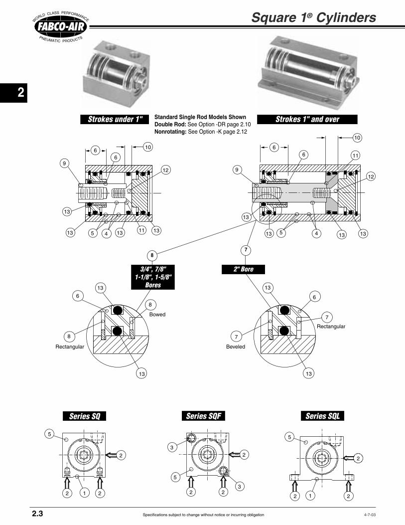
Specifications subject to change without notice or incurring obligation
2
4-7-03
Square 1® Cylinders
66
10
12
1311134
9
13
13 5
66
10
13
11
134
9
13
13 5
12
5
2 21
2
8
Bowed
6
Rectangular
13
13
8
Series SQ Series SQF Series SQL
Strokes 1" and overStrokes under 1"
7
2" Bore3/4", 7/8"1-1/8", 1-5/8"
Bores
8
2.3
13
6
13
7
Beveled
7
Rectangular
Standard Single Rod Models Shown Double Rod: See Option -DR page 2.10Nonrotating: See Option -K page 2.12
5
2 23
32
2 2
2
5
1
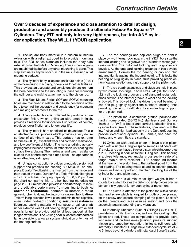
Specifications subject to change without notice or incurring obligation
2
Construction Details
1-17-08 2.4
1 The square body material is a custom aluminum
mounting surface.
2 ) or the bore during machining operations for other features. This provides an accurate and consistent dimension from the bore centerline to the mounting surface for mounting the cylinder and making attachments to the piston rod.
3 The Face Mount, Series SQF and SQFW, mounting holes are machined in relationship to the centerline of the bore to control the accuracy and consistency for mounting and making attachments to the rod.
4 The cylinder bore is polished to produce a fine crosshatch finish, which, unlike an ultra smooth finish, provides a reservoir for lubrication. Lubrication, of course, provides lower friction and longer seal life.
5 The cylinder is hard anodized inside and out. This is an electrochemical process which provides a very dense
and low coefficient of friction. The hard anodizing actually impregnates the base aluminum rather than just coating the surface like a plating. The hardness and wear resistance
is an attractive, satin gray.
6 Unique construction provides unequaled piston rod support and prohibits rod bushing BLOWOUT! The one-piece Duralon® rod bushing is inserted from the inside and then staked in place. Duralon® ® lined, fiberglass structure with load carrying capacity of 60,000 psi. See the chart comparing this to other bearing materials on page 2.2. Duralon® also provides: consistency- reliable and predictable performance from bushing to bushing; corrosion resistance- nonmetallic materials resist galvanic, chemical, and fretting corrosion; self lubrication-
® lining provides low friction and minimizes slipstick, even under no-load conditions; seizure resistance- fiberglass backing material will not seize or gall on shaft
over is longer to provide additional load support at the
far as possible to allow air system lubrication onto most of the bearing surface.
7 The rod bearings and cap end plugs are held in place by two internal lockrings. In the 2" (321) bore size the inboard lockring and its groove are of standard rectangular cross section. The outboard lockring and its groove are
arrangement, it drives the rod bearing or cap end plug into and tightly against the inboard lockring. This locks the bearing or plug rigidly in place, thus providing precision,
8 The rod bearings and cap end plugs are held in place by two internal lockrings. In bore sizes 3/4" (04) thru 1-5/8" (221) all the lockring grooves are of standard rectangular cross section. The internal groove is wider and the lockring is bowed. This bowed lockring drives the rod bearing or cap end plug tightly against the outboard lockring, thus
for the piston rod.
9 The piston rod is centerless ground, polished and hard chrome plated (68-72 Rc) stainless steel. Surface finish is 12 RMS or better and carries lubrication like our cylinder bore (see 4). These features, combined with the low friction and high load capacity of the Duralon® bushing
10 Cylinders with strokes under 1" have a thin piston head with a single O'Ring for space savings. Cylinders with 1" stroke and over have a thicker piston which incorporates a PTFE bearing in addition to the O'Ring seal. This bearing is a close tolerance, rectangular cross section strip of a tough, stable, wear resistant PTFE compound located at the rear of the piston head, the furthest point from the rod bearing. The bearing material and its location provide
cylinder bore and piston seal.
11 The piston is aluminum for light weight. It has a counterbore which locates the piston rod and provides precise concentricity control for smooth cylinder movement.
12 The piston is attached to the piston rod with a socket
on the screw and secure clamping of the piston. Loctite® on the threads and faces assures sealing and locks the assembly against pounding and vibration.
13 Internally lubricated Buna-N O'Rings (–25° to + 250° F) provide low profile, low friction, and long life sealing of the
long wear and low breakaway (starting) pressure, running friction and smoother operation. In tests, cylinders with
to 3 times beyond cylinders with standard Buna-N seals.
Over 3 decades of experience and close attention to detail at design, production and assembly produce the ultimate Fabco-Air Square 1® Cylinders. They FIT, not only into very tight spaces, but into ANY cylin-der application. They WILL fit YOUR application.

Specifications subject to change without notice or incurring obligation
2
Bore Series Available Stroke Lengths (Inches)
1/8 1/4 1/2 3/4 1 1-1/2 2 3 4 5 6
7/8" SQL06 ✔ ✔ ✔ ✔ ✔ ✔ ✔ ✔ ✔ NA NA
1-1/8" SQL 121 ✔ ✔ ✔ ✔ ✔ ✔ ✔ ✔ ✔ ✔ ✔
1-5/8" SQL 221 ✔ ✔ ✔ ✔ ✔ ✔ ✔ ✔ ✔ ✔ ✔
2" SQL 321 ✔ ✔ ✔ ✔ ✔ ✔ ✔ ✔ ✔ ✔ ✔
Bore Series Available Stroke Lengths (Inches)
1/8 1/4 1/2 3/4 1 1-1/2 2 3 4 5 6
3/4" SQ04 ✔ ✔ ✔ ✔ ✔ ✔ ✔ ✔ ✔ NA NA
1-1/8" SQ121 ✔ ✔ ✔ ✔ ✔ ✔ ✔ ✔ ✔ ✔ ✔
1-5/8" SQ221 ✔ ✔ ✔ ✔ ✔ ✔ ✔ ✔ ✔ ✔ ✔
2" SQ321 ✔ ✔ ✔ ✔ ✔ ✔ ✔ ✔ ✔ ✔ ✔
Side Tap Mounting: Series SQ
Face Mounting: Series SQF
Bore Series Available Stroke Lengths (Inches)
1/8 1/4 1/2 3/4 1 1-1/2 2 3 4 5 6
3/4" SQF04 ✔ ✔ ✔ ✔ ✔ ✔ ✔ ✔ ✔ NA NA
1-1/8" SQF 121 ✔ ✔ ✔ ✔ ✔ ✔ ✔ ✔ ✔ ✔ ✔
1-5/8" SQF 221 ✔ ✔ ✔ ✔ ✔ ✔ ✔ ✔ ✔ ✔ ✔
2" SQF 321 ✔ ✔ ✔ ✔ ✔ ✔ ✔ ✔ ✔ ✔ ✔
Model SQ 121-2
Model SQF 121-2
Model SQL 121-2
Side Lug Mounting: Series SQL
All Square 1® Mountings
Magnetic piston option does NOT affect stroke.
Magnetic piston option does NOT affect stroke.
Magnetic piston option does NOT affect stroke.
4-7-03
■ Double Acting – Single Rod Choice of "G" or "W" Rod Extension*■ For single acting use air spring as shown on page 1.15■ Double Acting – Double Rod Choice of combinations of "G" and "W" rod extensions*■ Female Rod End with Wrench Flats■ PTFE Piston Bearing; 1" Stroke and Up■ Internally lubricated Buna-N Seals (-25° to + 250°F)■ Operation to 150 psi■ Rod and Cap End Ports in Position 1A
*For Rod Extension Information See Dimension "G" and "W" on pages 2.6, 2.7 or 2.8.
CAD Drawings on CD-ROMA complete library of cylinder CAD draw-
ings is available. Contact your local dis-
tributor for details, download from our web
site http://www.fabco-air.com
or E-Mail us at [email protected]
Standard Specifications
Side view (opposite ports) shows mounting holes and
relief for mounting rails.
2.5

Specifications subject to change without notice or incurring obligation
2
Model Number Code
OPTIONSDescription Specify See Page
Male Rod Thread 2.9 Single Rod -MR Double Rod, Rod End -MR Double Rod, Cap End -MR1 Double Rod, Both Ends -MR2Viton Seals (-15° to +400°F) -V 2.9Quad Seals -Q 2.9Metric Rod Thread -M 2.9Nonrotating -K 2.12 1-1/8", 1-5/8", 2" bores onlyPort Positions -1B 2.9
-G 2.14 Hydraulic, Low Pressure -H 2.9 to 150 psi NONSHOCKDouble Rod -DR 2.10Hole Thru Double Rod Shaft 2.10 Bore Hole 3/4", 7/8" 1/16" -DR06 1-1/8" 1/8" -DR13 Plus size 5/32" -DR16 1-5/8" 1/8" -DR13 Plus size 1/4" -DR25 2" 5/32" -DR16 Plus size 5/16" -DR31Stroke Collar 1/8" C1 2.11 1/4" C2 3/8" C3 1/2" C4 5/8" C5 3/4" C6 7/8" C7Sound Limiters 2.11 Rod End -LF Cap End -LR Both Ends -LFRAdjustable Retract Stroke -RS 2.11 For over 1" adjustment add desired length: e.g. -RS2
for Piston Position Sensors -E (Order Sensors separately.)
– –121 2 MR
Mounting
SQSide Tap
SQFFace
SQLSide Lug
Bore
04 for 3/4" bore
06 for 7/8" bore
121 for1 1/8" bore
221 for 1-5/8" bore
321 for2" bore
Rod Extension
Single Rod Models
Blank –for standard
sion "G" on page 2.7
W - for Extension to dimension "W" on page 2.7
Double Rod Models
See Page 2.10
Blankboth ends
Wboth ends
GW-
sion on cap end
WG-
sion on cap end
StandardStrokesInchesBores3/4"7/8"1/81/41/23/41
1-1/2234
Bores 1-1/8"1-5/8"
2"1/81/41/23/41
1-1/223456
SQ
How to Order
2. Specify Bore3. Specify Stroke in Inches and Fractions4. Specify Options
ExamplesSQ 121 - 2
1-1/8" Bore; 2" Stroke
SQW 121 -2 - MR
1-1/8" Bore; 2" Stroke; Male Rod Thread
SQLW 06 - 3 - C2 - LR
7/8" Bore; 3" Stroke with 1/4" Stroke Collar yielding 2-3/4" Net Stroke; Sound Limiter, Cap End
Mounting Kits for Series SQF Type See PageFlange Mount Kit 2.14Trunnion Mount Kit 2.15Clevis Bracket Kit 2.15Eye Bracket Kit 2.15Rod Clevis 2.15
How To Order
7-2-01 2.6

Specifications subject to change without notice or incurring obligation
2 G or WY Z + Stroke
A–2
A
X
B + Stroke
M + StrokeL
RodEnd
Face
CapEnd
FaceN1
1
2
3
4
K1
K1–2
J (Ref.)
E
Port Position
1B
H
Port Position
1A
A–2
A
PF
G or WY
Z + StrokeB + Stroke
L N1
P
Cylinders with less than 1" stroke have 2 mounting holes
Cylinders with 1" stroke or more have 4 mounting holes
SQ Series: Side Tap Mounting – 3/4", 1-1/8", 1-5/8" and 2" Bores
4-7-03
Square 1® Cylinders
2.7
G or W
A–2
A
X
1
2
3
4
K2
K2––2
J (Ref.)J (Ref.)
T2E S2
Port Position
1B
H
Port Position
1A
A–2
A
F G or WY Z + Stroke
B + Stroke
RodEnd
Face
P
Y
Z + StrokeB + Stroke
L N2
P
M + StrokeL N2
Cylinders with less than 1" stroke have 2 mounting holes
Cylinders with 1" stroke or more have 4 mounting holes
Washer Supplied with cylinder for use under mounting bolt head to prevent cylinder movement while tightening bolt
SQL Series: Side Lug Mounting – 7/8", 1-1/8", 1-5/8" and 2" Bores
Fixed Dimensions
A1.251.251.502.002.50
F Dia..31.31.50.62.75
G.13.13.19.19.19
H1/41/47/161/25/8
J.19.19.19.25.25
K1.88–
1.131.502.00
R.19–
.19
.25
.25
Bore3/4"7/8"
1-1/8"1-5/8"
2"
K2–
1.631.882.503.00
N1
–
U.75–
.75
.75
.75
P10-3210-321/81/81/8
N2–
.21
.21
.27
.27
S1.88–
1.131.502.00
T2–
.02
.02
.03
.03
W.38.38.381.001.00
S2–
.19
.19
.25
.31
X.31.31.28.31.38
T1(Note 2)
–(Note 2)(Note 2)
(Note 3)
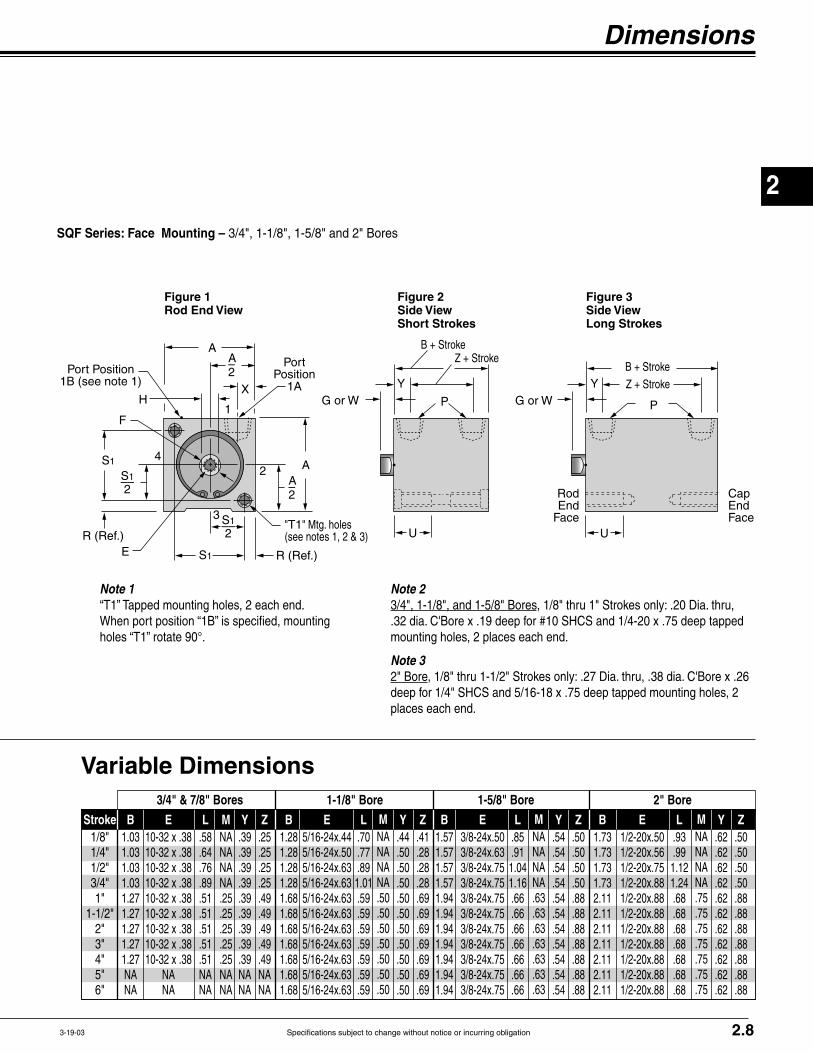
Specifications subject to change without notice or incurring obligation
2
Dimensions
3-19-03
A–2
A
X
1
2
3
4
S1 R (Ref.)E
Port Position 1B (see note 1)
H
Port Position
1A
A–2
A
F
S1
R (Ref.)"T1" Mtg. holes
G or WY Z + Stroke
B + Stroke
RodEnd
Face
CapEndFace
P
Y
Z + StrokeB + Stroke
P
UU
S1––2
S1––2
G or W
Figure 2Side ViewShort Strokes
Figure 3Side ViewLong Strokes
Figure 1Rod End View
SQF Series: Face Mounting – 3/4", 1-1/8", 1-5/8" and 2" Bores
2.8
Variable Dimensions
B1.031.031.031.031.271.271.271.271.27NANA
E
NANA
L.58.64.76.89.51.51.51.51.51NANA
Stroke1/8"1/4"1/2"3/4"1"
1-1/2"2"3"4"5"6"
3/4" & 7/8" Bores 1-1/8" Bore 1-5/8" Bore 2" Bore
Y.39.39.39.39.39.39.39.39.39NANA
Z.25.25.25.25.49.49.49.49.49NANA
MNANA NANA.25.25.25.25.25NANA
B1.281.281.281.281.681.681.681.681.681.681.68
E L.70.77.89
1.01.59.59.59.59.59.59.59
Y.44.50.50.50.50.50.50.50.50.50.50
Z.41.28.28.28.69.69.69.69.69.69.69
MNANA NANA.50.50.50.50.50.50.50
B1.571.571.571.571.941.941.941.941.941.941.94
E L.85.91
1.041.16.66.66.66.66.66.66.66
Y.54.54.54.54.54.54.54.54.54.54.54
Z.50.50.50.50.88.88.88.88.88.88.88
MNANA NANA.63.63.63.63.63.63.63
B1.731.731.731.732.112.112.112.112.112.112.11
E L.93.99
1.121.24.68.68.68.68.68.68.68
Y.62.62.62.62.62.62.62.62.62.62.62
Z.50.50.50.50.88.88.88.88.88.88.88
MNANA NANA.75.75.75.75.75.75.75
Note 2 3/4", 1-1/8", and 1-5/8" Bores, 1/8" thru 1" Strokes only: .20 Dia. thru,
mounting holes, 2 places each end.
Note 3 2" Bore
places each end.
Note 1 “T1” Tapped mounting holes, 2 each end. When port position “1B” is specified, mounting holes “T1” rotate 90°.

Specifications subject to change without notice or incurring obligation
2
4-7-03
Male Rod Thread Option
Single Rod -MR Double Rod, Rod End Only -MR Double Rod, Cap End Only -MR1 Single Rod, Both Ends -MR2
Viton Seals Option -V
Metric Rod Thread Option -M
Quad Seals Option -Q
Ports Position Option -1B
Hydraulic Option -H
Square 1® Cylinders
2.9
A high strength stud is threaded into the standard female rod end and retained with Loctite®. This method eliminates the small diameter thread relief area normally
required when machining male threads. It provides a much stronger rod end which can be repaired, rather than replacing the complete rod, should the thread be damaged.
For elevated temperatures (–15°F to
Consult engineering for compatibility information.
Thread
Bore Thread
A QUAD seal replaces the standard O'Ring on the piston only. Standard seal material is Buna-N with operating temperatures of –25°F to + 250°F. Consult engineering for other materials.
Both ports are located at Posi-tion 1B (see drawings on page 2.7). This position is achieved by reverse assembly of the cylinder. Therefore, it is a no-charge option. Please note that on Series SQF and SQFW the mounting holes rotate 90°.
For Air-over-Oil or Hydraulic systems to 150 psi, NONSHOCK. Where space permits, a U-cup rod seal or an additional rod O'Ring is
Ports can be located in other positions on a special basis. Consult engineering with application requirements for details on other locations.
incorporated in the rod bearing to
rod seal.
Rod threads are configured in common METRIC sizes. To arrive at Female Rod Thread depth in mm, multiply English depth by 25.4. See page 2.15 for Metric Rod Clevis.
Rod
Loctite®No ReliefNo weakness
Stud
See page 2.15 for Metric Rod Clevis
Low pressure serviceto 150psi NONSHOCK
Bore Female Rod Thread Pitch Male Rod Thread x Length

Specifications subject to change without notice or incurring obligation
2
Option Specifications
7-3-01
Double Rod Option -DR
Hole Thru Double Rod Shaft
Single Rod Models Blank per dimension "G". W dimension "W".
Double Rod Models Blank– "G" both ends. W GW
WG
G or W + StrokeG or W
Rod End Cap End
Standard piston rod and rod bushing on both ends of the cyl-inder. Counterbores on both sides of the piston maintain concentricity of the piston rods to each other as well as to the piston O-ring.
The piston rods are connected by a high strength stud, sandwiching the piston between the rod faces. The assembly is torqued for proper preload of the stud and clamping of the piston head. Loctite® on the threads and faces assures sealing and locks the assembly against pounding and vibration.
A hole is drilled through the pis-ton rods and the double rod stud. This hole is used for the passage of Vacuum, Air, Gas, Liquid, or any media that is compatible with the stainless steel piston rod and the
SQ . . . . . . -DRSQW . . . . -DR SQGW . . . -DR
SQWG . . . -DR
SQF . . . . . -DRSQFW . . . -DR SQFGW . . -DR
SQFWG . . -DR
SQL . . . . . -DRSQLW . . . -DR SQLGW . . -DR
SQLWG . . -DR
2.10
Piston
CounterboresRod
Rod
Stud
This procedure provides a positive and rigid assembly that will not
pounded loose.The PTFE piston bearing is
not required because the two rod
support.Use when attachment to both
ends of the cylinder is required or to indicate piston position.
The ava i lab i l i t y o f 2 rod
model combinations as shown in the listings at the left.
for each bore is shown in the chart below.
The PTFE piston bearing is not required because the two rod
support.
Note: When using stroke collars in double rod units, CAP END ROD STICK-OUT increases by amount stroke is shortened.
Rod Rod
Piston
StudHole Thru Standard Standard Plus Model No. Model No. Hole Size Suffix Hole Size Suffix Bore thru stud (Std) thru stud (Std Plus)
3/4", 7/8" 1/16 -DR06 – – 1-1/8" 1/8 -DR13 5/32 -DR16 1-5/8" 1/8 -DR13 1/4 -DR25 2" 5/32 -DR16 5/16 -DR31
Rod Extension Dimensions
Bore 3/4" 7/8" 1-1/8" 1-5/8" 2" G .13 .13 .19 .19 .19 W .38 .38 .38 1.00 1.00

Specifications subject to change without notice or incurring obligation
2
10-23-04
Stroke Collar on piston rod Option
1/8" -C1
1/4" -C2
3/8" -C3
1/2" -C4
5/8" -C5
3/4" -C6
7/8" -C7
Square 1® Cylinders
2.11
An adjusting screw with a thread sealing locknut mounted in the Cap End Plug provides a simple, yet rugged and precision adjustment of the cylinder stroke in the retract direction. Bores 3/4", 7/8", and 1-1/8" have a 5/16"-24 thread giving 0.042" adjustment per revolution. Bores 1-5/8" and 2" have a 1/2-20 thread giving 0.050" adjustment per revolution.
The -RS designation provides full stroke adjustment of any cylinder with 1" stroke or less, and 1" stroke adjustment on all longer strokes. When specifying longer adjustments on longer cylinders, add the desired adjustment to the -RS designation (1/2" increments, please).
Example: -RS2 will provide 2" of adjustment on any cylinder with 2" or more stroke.
How to Order-
gest stroke cylinder.2) Select the amount the stroke is to be shortened.3) Use the corresponding designation immediately after the stroke in the model number.
For those “in-between” strokes, a STROKE COLLAR of Delrin® is incorporated on the piston rod. The collar fits tightly on the piston rod so
stroked. Tolerance on the stroke is ± 1/64". For tighter tolerances on the stroke or final rod position, contact engineering with application details.
For applications where you need a small amount of cushion at the end of the cylinder stroke to take out the metallic “slap” of piston head
on piston stop. This is accomplished by placing an O'Ring on the rod at the piston, and/or in the cap end plug so that initial contact is with the elastomer and not metal-to-metal.
The Fabco-Air design assures sufficient compression of the seals to allow full stroke.
Because of the temperature limitations of the adhesives involved, sound limiters are available in cylinders with internally lubricated Buna-N O'Rings only.
Stroke collar of Delrin®
Sound Limiters Option
Rod End Only -LF Cap End Only -LR
-LFR
Note: When using stroke collars in double rod units, CAP END ROD STICK-OUT in-creases by amount stroke is shortened.
Adjusting Screw
Thread sealing locknutAny stroke with up to and including 1" adjustment. Any stroke with over 1" adjustment, specify the adjustment length after the -RS.
2" Adjustment = -RS2
Sound limiting O'Ring Cushions
Option -LFR shown
Adjustable Retract Stroke Option -RS

Specifications subject to change without notice or incurring obligation
2
Wrench flat random rotation
An internal piston guide pin prohibits rod rotation so that objects attached to or moved by the rod will not rotate. Incorporating the guide mechanism inside the cylinder saves you the time, space and cost
and bushings in and around your mechanism. The guide pin and bushing are also protected from damage by the environment, the atmosphere, or mechanical abuse. These internal parts are lubricated by the system lubrication.
Option Specifications
2.12
Construction Details
1. The aluminum piston is attached to the piston rod with a
is torqued for proper preload of the screw and clamping of the piston. Loctite® on the threads and faces assures sealing and locks the assembly against pounding and vibration.
2. PTFE bearing is standard in 1" strokes and longer for single rod models.
3. The non-rotating guide pin is ground tool steel for precision and long life. Incorporated inside the cylinder it is protected from environmental dirt and grime and mechanical abuse. It receives lubrication from the air system lubricator.
Available in 1-1/8", 1-5/8", and 2" bores.
May be used in conjunction with all options including -E piston position sensing.
Rotational accuracy is ±1°. The warning label shown at the left is applied to each cylinder.
4. A precision machined guide pin support block is attached to each
screw. These support blocks provide rigid and precise location of the guide pin.
5. The guide pin passes through a polyurethane O-ring seal and an SAE660 bearing bronze bushing installed in the piston head. This combination provides "no-leak" precision guiding and long life.
6. A disk of rubber is included at the end of the guide pin to take up end play and firmly seat the pin in its support blocks.
Cutaway view of Model SQL 321 - 4 - K
Nonrotating Option -K
1-1/8", 1-5/8", and 2" bores only
WARNINGTHIS CYLINDER HAS A NONROTATING ROD. TO PREVENT INTERNAL DAMAGE HOLD ROD BY WRENCH FLATS WHEN INSTALLING OR REMOVING ATTACHMENTS.
10-23-04

Specifications subject to change without notice or incurring obligation
2 Dovetail style sensors are actuated by a magnetic piston.
slot on the cylinder body, is positioned as desired, and locked in place with a set screw.
Option "E" in the model number.
Order sensors separately.
Magnetic Piston Option -EIncludes Dovetail Mounting Slots Order Sensors Separately
Encased in plastic housing, dovetail style sensors are corrosion resistant. 60° wire outlet allows close mounting. Profile shown here is typical.
Low Profile, Solid State, Magnetic Piston Position Sensors
Temperature Range: –20° to +80°C (–4° to +176°F)
This short stroke Model SQF requires two dovetail mounting slots for proper positioning of sensors to detect begin-ning and end of stroke.
This longer stroke Model SQL, side lug mounting style, has room enough to fit multiple sensors in a single slot.
Standard Stroke & Slot Location Guide SQ (Side Tap) SQF (Face Mount) SQL (Side Lug)
Rod End
Port
SQ Profile SQF Profile SQL Profile
Square 1® Cylinders
2.13
Note*: Quick disconnect styles are supplied with 6 inch pigtail with male connector. Order female cordsets separately.
Electrical CharacteristicsQuick Disconnect
Part No.*
949-000-331949-000-332
Prewired 9 ft.Part No.
949-000-031949-000-032
Sensor Type
ElectronicElectronic
LED
YesYes
Dovetail Style Magnetic Sensors for Square 1® Cylinders
Cylinder Model
All Square 1'sAll Square 1's
Length1 Meter2 Meters5 Meters
Part No.CFC-1MCFC-2MCFC-5M
Female Cordsetsfor
Quick Disconnect
1-31-08
Sensor Slots atPositions #2 and #4
Sensor Slot at Position #2 only
3/4" 1 1/8" 1 5/8" 2" 3/4" 1 1/8" 1 5/8" 2" 7/8" 1 1/8" 1 5/8" 2" Stroke 04 121 221 321 04 121 221 321 06 121 221 321 1/8 ✓ ✓ ✓ ✓ ✓ ✓ ✓ ✓ ✓ ✓ ✓ ✓ 1/4 ✓ ✓ ✓ ✓ ✓ ✓ ✓ ✓ ✓ ✓ ✓ ✓ 1/2 ✓ ✓ ✓ ✓ ✓ ✓ ✓ ✓ ✓ ✓ ✓ ✓ 3/4 ✓ ✓ ✓ ✓ ✓ ✓ ✓ ✓ ✓ ✓ ✓ ✓ 1 ✓ ✓ ✓ ✓ ✓ ✓ ✓ ✓ ✓ ✓ ✓ ✓ 1-1/2 ✓ ✓ ✓ ✓ ✓ ✓ ✓ ✓ ✓ ✓ ✓ ✓ 2, 3, 4 ✓ ✓ ✓ ✓ ✓ ✓ ✓ ✓ ✓ ✓ ✓ ✓ 5, 6 NA ✓ ✓ ✓ NA ✓ ✓ ✓ NA ✓ ✓ ✓

Specifications subject to change without notice or incurring obligation
2
External Guide, Nonrotating Option -G
steel for long wear and corrosion resistance.
for long wear and corrosion resistance.
provide for adjustment and backlash control, compensation for wear, and minimal rotation.
superior nonrotation and support.
between cylinder and guide bar mounting block to eliminate pinch points.
Option Specifications
2.147-26-01
E R
TF2
UF
A Sq. G†
Series SQF
F
FB4 Dia.4 Places
X
1B
1A1
2B
2A
3B3A
4B
42
3
4A
FB2 Dia.2 Places
TF4
Flange Mounting Kits for Series SQF and SQFW
Flange Style 7
Flange Style 8 & 9
Bore3/4"
1-1/8"1-5/8"
2"2"
A1.251.502.002.502.50
Kit #H7-04
H7-121H7-221H8-321H9-321
Model04121221321321
Style77789
E1.501.502.002.502.50
F.25.25.38.38.38
FBNANANA.38.28
FB2.22.22.22NANA
FB4.22.22.31NANA
G†.13.19.19.19.19
R1.001.001.431.842.00
TFNANANA
3.383.00
TF21.752.002.50NANA
TF42.002.002.75NANA
UF2.502.503.384.133.50
W‡0.380.381.001.001.00
X.38.56.69.81.81
Port Positions1A Standard all models.
For 1B, specify Option -1B For 2B, 3B, or 4B: Specify Option -1B
Flange Bore Fabco Mounting Hole Pattern Style Size Kit No. Interchange Information
7 3/4" H7-04
7 1-1/8" H7-121
7 1-5/8" H7-221
8 2" H8-321
9 2" H9-321
4 Hole Pattern
2 Hole Pattern
4 Hole Pattern
2 Hole Pattern
4 Hole Pattern
All brands conforming to this code2 Hole Pattern
4 Hole Pattern
All brands conforming to this code
4 Hole Pattern
Kits include Flange and 2 Flange Mounting Screws
E R
TFUF
A Sq. W‡
Series SQFW
F
FB Dia.4 Places
X
1B
1A1
2B
2A
3B3A
4B
42
3
4A
SQFW-121-11/2with H7-121
Mounting Series SQ or SQF Model 04 121 221 321 Bore 3/4" 1 1/8" 1 5/8" 2" AA 1.25 1.50 2.00 2.50 BB .63 .69 .69 .69 CC .63 .63 .63 .75 DD 1.94 2.26 2.75 3.25 EE .87 1.06 1.50 1.88 FF 2.19 2.50 3.00 3.50 GG .63 .63 .75 1.00 HH 1.00 1.00 1.00 1.00 JJ .19 .25 .25 .25
B + StrokeCCCC
BB
DD
DD__2
Mounting Block Clear Anodized Aluminum
JJ Square Guide PinsHard Chrome Plated Steel
Guide Block Hard Anodized Aluminum
AA SquareRef.
GG
HH
EE FFEE__2
Clearance in Guide BlockMounting Holes allow foradjustment to compensate for wear
KK Mounting Holes 2 Places
Superior nonrotating piston rod feature for applications such as package placement, figure stamping, and any application where anti-rotation and registration are critical as
A mounting block is bolted to the piston rod. This block has two square pins mounted to it which in turn pass through guide blocks mounted on the sides of the cylinder.
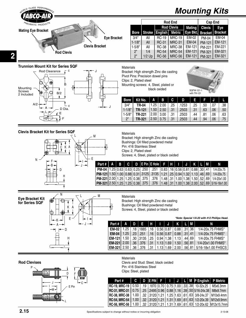
Specifications subject to change without notice or incurring obligation
2
Mounting Kits
Eye Bracket Kitfor Series SQF
Trunnion Mount Kit for Series SQFc
cA/2
B
B/2
AL E
F
D Dia.
MountingScrews2 Included
Rod Clearance J
J
N L M
IJ
H
AK
AK
E
D
C K A
IJ
E
ML
FB
N
D
H
Clevis Bracket Kit for Series SQF
Mating Eye Bracket
Rod Clevis
Clevis Bracket
Eye Bracket
Rod Clevises
MI
J
P
E PinC
D F
L
Materials
Pin: 416 Stainless SteelClips: Steel, plated
MaterialsBracket: High strength Zinc die castingBushings: Oil filled powdered metal
MaterialsBracket: High strength Zinc die castingBushings: Oil filled powdered metalPin: 416 Stainless SteelClips: 2, Plated steel
MaterialsBracket: High strength Zinc die castingPivot Pins: Precision dowel pinsClips: 2, Plated steelMounting screws: 4, Steel, plated or
2.15 2-13-08
Kit No.TR-04TR-121TR-221TR-321
A1.251.502.002.50
B2.002.503.003.75
C.25.31.31.31
D.1253.2503.2503.2503
E.25.31.44.44
F.50.63.81.94
J.07.06.06.06
L.38.50.63.75
Bore3/4"
1-1/8"1-5/8"
2"
StrokeAllAllAll1/4
1/2 Up
Bore3/4"
1-1/8"1-5/8"
2"2"
Rod ClevisEnglishRC-19RC-31RC-38RC-54RC-56
MetricMRC-19MRC-31MRC-38MRC-54MRC-56
Rod End Cap EndClevis
BracketPM-04PM-121PM-221PM-321PM-321
Mating Eye Bkt.EM-02EM-04EM-121EM-121EM-121
Eye BracketEM-04EM-121EM-221EM-321EM-321
C0.500.751.001.001.00
D.19.25.32.32.32
E PIN.1870.2495.3120.3120.3120
F0.700.961.211.211.21
I0.750.881.251.311.31
Part #RC-19, MRC-19RC-31, MRC-31RC-38, MRC-38RC-54, MRC-54RC-56, MRC-56
J1.001.161.631.691.69
L.33.39.61.61.61
M.38.50.63.63.63
P English P Metric
SQFW-121-1with TR-121
A1.251.251.502.002.50
D.18.23.30.36.36
E.1885.251.3135.376.376
H.16.16.25.31.31
I0.560.560.941.131.13
Part #EM-02EM-04EM-121EM-221EM-321
J0.870.871.381.691.69
K0.880.881.131.502.00
L.31.31.44.56.56
M.36.41.69.81.81
N
*Note: Special 1/4-20 with #12 Phillips Head.
A1.251.502.002.50
B0.631.001.251.25
C0.630.881.251.25
D0.250.310.380.38
E Pin.250.3125.375.375
F0.831.211.481.48
H.16.25.31.31
I0.560.941.001.00
Part #PM-04PM-121PM-221PM-321
E Hole.251.3135.376.376
J0.811.321.381.38
K0.881.131.502.00
L.30.46.52.52
M.41.69.69.69
N
Specifications subject to change without notice or incurring obligation
2
Cylinders, Valves, & Accessories
Notes

Specifications subject to change without notice or incurring obligation
3
6-4-01
Page
Features & Benefits ..................................................................................... 3.2
General, Standard Ratings .......................................................................... 3.2
Construction Information ............................................................................. 3.3 How a Longstroke™ is built
Model Number Chart ................................................................................... 3.4 How to Order
Option List ................................................................................................... 3.4
Standard Specifications ............................................................................... 3.5 - 3.6
Option Specifications ................................................................................... 3.7 - 3.9 Description of the Options
Mounting Kits .............................................................................................. 3.10
Accessories ................................................................................................ 3.10
Air Spring Return ......................................................................................... 1.15
Position Sensors .......................................................................................... 3.9
Directional Control Valves ............................................................................ Section 11
Port Mounted Flow Control Valves ............................................................... Section 12
Specials ....................................................................................................... ii & iii
2 Year Warranty............................................................................................ Inside back cover
Round Head and Square Head Tie Rod Cylinders
S521-7-MR
521-7
3.1

Specifications subject to change without notice or incurring obligation
3
Bore Diameter 2" 2-1/2" 3" 4"Rod Diameter 0.75 0.75 0.75 0.88Rod Area 0.44 0.44 0.44 0.79Push Area (Single Rod) 3.14 4.91 7.07 12.57Pull Area 2.70 4.47 6.63 11.97Round Head Base Weight, lb. 2.21 2.83 3.66 5.98Square Head Weight, lb. 2.34 3.08 3.27 5.20Weight Per Inch, lb. 0.18 0.21 0.23 0.34
4-0-08
® rod bushing
piston and rod seals.
. . . . . . . . . . . . . . . . . . . . . . . . . . . . . . . . . . . . .Air . . . . . . . . . . . . . . . . . . . 250 psi
. . . . . . . . 15 psi . . . -25° to +250°F
. . . . . . . . . . . . . . Magnalube®–G Grease . . . . . . . . . . . . . . . . . . . . . . . . . ± 1/64"
. . . . . . . . . . . . . 500 psi nonshock
Square Head Style
Round Head Style
Available in 2 styles4 Bore sizes 2" thru 4"Strokes to 12"
Longstroke™ Cylinders
Ratings – Standard Units all series
Sizing Guide
Piston Rod Bushing, anodized aluminum ® lined Duralon® insert
Groove for magnetic piston position sensing
PTFE Bearing Strip is located away from rod bearing for
Load Capacity (psi) Machine Design 1972/73 Bearing Reference IssuePorous Bronze .............. 4,500Porous iron .................. 8,000Phenolics ..................... 6,000Nylon® ........................ 1,000TFE .............................. 500Reinforced Telfon® ..... 2,500*TFE fabric .................. 60,000Polycarbonate ............. 1,000Acetal .......................... 1,000Carbon-graphite .......... 600
* Shows Duralon bearing classification. Not to be used for design purposes.
Friction Properties Slip- Coefficient stickSteel-on-steel ................. .50 YesBronze-on-steel .............. .35 YesSintered Bronze-on-steel with mineral oil ...... .13 NoBronze-on-steel with mineral oil ....... .16 NoCopper lead alloy-on-steel .22 YesAcetal-on-steel .............. .20 NoNylon-on-steel ............... .32 YesDuralon-on-steel ............ .05 - .16 No
Duralon® Rod Bearings Excel
Printed with permission by Rexnord Corp.
Piston Seal, internally lubricated O'Ring for long life and improved performance
3.2

Specifications subject to change without notice or incurring obligation
3
4-1-08
Longstroke™ Cylinders
Cylinder OD – is clear anodized aluminum for corrosion resistance and an attractive appearance.
The Bore ID is Hard Anodized – Hard anodizing is an electrochemical process which provides a very dense
with a low coefficient of friction. Hardness, corrosion
plated steel.
An Extra Long Rod Bearing – provides long and rigid support for the piston rod. The bearing material is Duralon® on all bore sizes. See page 3.2 for a chart comparing
® to other common, though less durable, bearing materials.
The Piston Rod – is Hard Chrome Plated Stainless Steel. The standard rod end is fine female thread tapped
Standard ModelsStandard: Single Rod, Double Acting
Option -DR: Double Rod, see page 3.7
Option -K: Nonrotating, see page 3.8
1
3
8
6
21
20 19 7 9 2
16
3
12
4 4
16 10
18 17 11 13 15 14
5
1
3
8
6
21
20 19
16
3
18 15 14
225
12
26
24
23 17 11 13
7 9 16 10
Basic ConstructionQuick Reference to Components
No. Description
1 Rod End Head, aluminum, black anodized 2 Cap End Head, aluminum, black anodized
4 1/4 NPT Ports
6 Piston Rod Bushing, anodized aluminum ® lined Duralon® insert
7 Piston Stop 8 Rod Seal, internally lubricated O'Ring for long life 9 Piston Rod, stainless steel, centerless ground,
10 Piston, aluminum 11 Counter bore locates piston rod to maintain precise concentricity 12 Piston Bolt, steel, Loctited® and torqued 13 Piston Seal, internally lubricated O'Ring for long life and improved performance14 PTFE Bearing Strip is located away from rod
15 Groove for magnet to activate position sensors16 O'Ring bumpers reduce metallic slap of piston on piston stop for quiet operation 17 Cylinder Tube, aluminum
18 Cylinder Tube end seal 19 Stainless steel tie rods
22 Steel double rod stud, Loctited® and torqued 23 Guide pin, precision ground tool steel 24 Guide pin bushing, SAE 660 bearing bronze 25 Guide pin seal, Urethane O'Ring 26 Rubber disk prevents guide pin movement
1
3
8
6
21
20 19 7 9 10 2
16
3
22
54 4
18 17 11 13 15 14
6
89
16
3.3
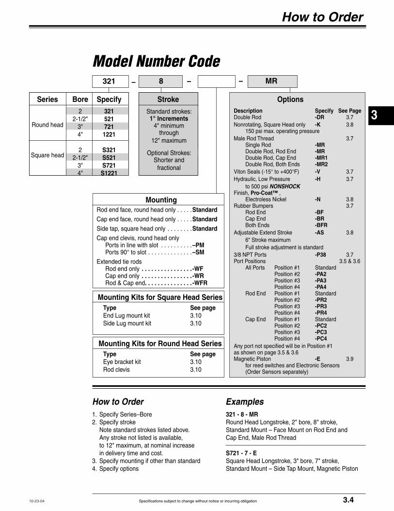
Specifications subject to change without notice or incurring obligation
3
How to Order
How to Order
10-23-04
1. Specify Series–Bore2. Specify stroke Note standard strokes listed above. Any stroke not listed is available,
in delivery time and cost.3. Specify mounting if other than standard4. Specify options
Examples321 - 8 - MRRound Head Longstroke, 2" bore, 8" stroke, Standard Mount – Face Mount on Rod End and Cap End, Male Rod Thread
S721 - 7 - ESquare Head Longstroke, 3" bore, 7" stroke, Standard Mount – Side Tap Mount, Magnetic Piston
Description Specify See PageDouble Rod -DR 3.7Nonrotating, Square Head only -K 3.8
Male Rod Thread 3.7 Single Rod -MR Double Rod, Rod End -MR Double Rod, Cap End -MR1 Double Rod, Both Ends -MR2
-V 3.7Hydraulic, Low Pressure -H 3.7 to 500 psi NONSHOCKFinish, Pro-Coat™ , Electroless Nickel -N 3.8Rubber Bumpers 3.7 Rod End -BF Cap End -BR Both Ends -BFR
-AS 3.8
Full stroke adjustment is standard3/8 NPT Ports -P38 3.7Port Positions 3.5 & 3.6
-PA2-PA3-PA4
-PR2-PR3-PR4
-PC2-PC3-PC4
as shown on page 3.5 & 3.6Magnetic Piston -E 3.9 for reed switches and Electronic Sensors
Options
Model Number Code– MR
MountingRod end face, round head only . . . . .StandardCap end face, round head only . . . . .StandardSide tap, square head only . . . . . . . .StandardCap end clevis, round head only Ports in line with slot . . . . . . . . . .–PM Ports 90° to slot . . . . . . . . . . . . . .–SM
Rod end only . . . . . . . . . . . . . . . . -WF Cap end only . . . . . . . . . . . . . . . . -WR Rod & Cap end . . . . . . . . . . . . . . . -WFR
– 8321
Series
Round head
Square head
–
Mounting Kits for Square Head Series Type See page End Lug mount kit 3.10 Side Lug mount kit 3.10
Specify3215217211221
S321S521S721S1221
Bore2
2-1/2"3"4"
22-1/2"
3"4"
Mounting Kits for Round Head Series Type See page Eye bracket kit 3.10 Rod clevis 3.10
Stroke
Standard strokes: 1" Increments
4" minimum through
Optional Strokes:Shorter and
fractional
3.4

Specifications subject to change without notice or incurring obligation
3
Longstroke™Cylinders
HA
1/2" Hex Nut30° 22.5° 21.5°
1
3.81 BC5.00 BC
32
41
3
2
4
1
32
43.25 BC
90° 1
3 2
2.81 BC
.33 Dia. .33 Dia. .33 Dia..33 Dia.
1.00
F Rod Dia.
3.38" + Stroke
0.25
0.50 0.501/4 NPT 1/4 NPT
1.00
K FemaleRod Thread
2" Bore 4" Bore3" Bore2-1/2" Bore
2.13" + Stroke
Rod End Cap End
Round Head, Standard, Face Mount Rod and Cap End
ZZ
BC
WF WR
BC
Rod End Cap End
2-1/2", 3", & 4" Bores4 Tie Rods
Equally Spaced
2" Bore3 Tie Rods
Equally Spaced
5/16-24 Thread
Dimensions
EE
0.25
JJ
FF-PM Port locations in line with slot
M
-SM Port locations 90° to slot
HH GG
3.38 + StrokeBB + Stroke
Round Head Clevis Mount Option Specify mounting option Ports in line with slot -PM Ports 90° to slot -SM
Extended Tie Rod Mount for Round Head Models Specify mounting option Rod End Only - WF Cap End Only -WR Rod and Cap Ends -WFR
7-17-01 3.5
Bore 2"
2-1/2"3"4"
A3.253.754.255.50
F Dia..750.750.750.875
H.63.63.63.75
E3.003.503.504.50
CNA
1.751.752.25
EE1.251.631.632.00
FF.38.50.50.63
GG Pin.3745.4995.4995.6245
HH0.690.970.971.22
GG Hole.376.501.501.626
BB4.134.384.384.63
BC2.813.253.814.63

Specifications subject to change without notice or incurring obligation
3
1.00H
E
1/2He
K FemaleThread
3.38"+ Stroke
0.25
0.50 0.50
1/4 NPT 1/4 NPT
1.00
C
E
Rod EndPort
0.81
TNTN
2.19
T
E
TH TH
NT NT
Cap EndPort 1
4
3
2
1
4
3
2
F Rod Dia.
N + Stroke
2.13"+ Stroke
2-1/2", 3", & 4" Bores2" Bore
Square Head, Standard, Side Tap Mount
WF WR
Rod EndPort
0.812.19
TH
Cap EndPort
BC BC
Rod End Cap End5/16-24 Thread
2-1/2", 3", & 4" Bores4 Tie Rods
Equally Spaced
2" Bore3 Tie Rods
Equally Spaced
Extended Tie Rod Mount for Square Head Models Specify mounting option Rod End Only - WF Cap End Only -WR Rod and Cap Ends -WFR
1-17-08
Dimensions
3.6
WR1.31.31.41.4
TN0.8751.2501.5002.060
WF1.31.31.41.4
NT TH1.3751.7501.7502.250
T.69.63.75.75
KJJ1.481.861.862.24
M.38.50.50.63
N2.252.382.132.13
Z60°30°
22.5°23.5°
Note:
are not available
Note:
are not available
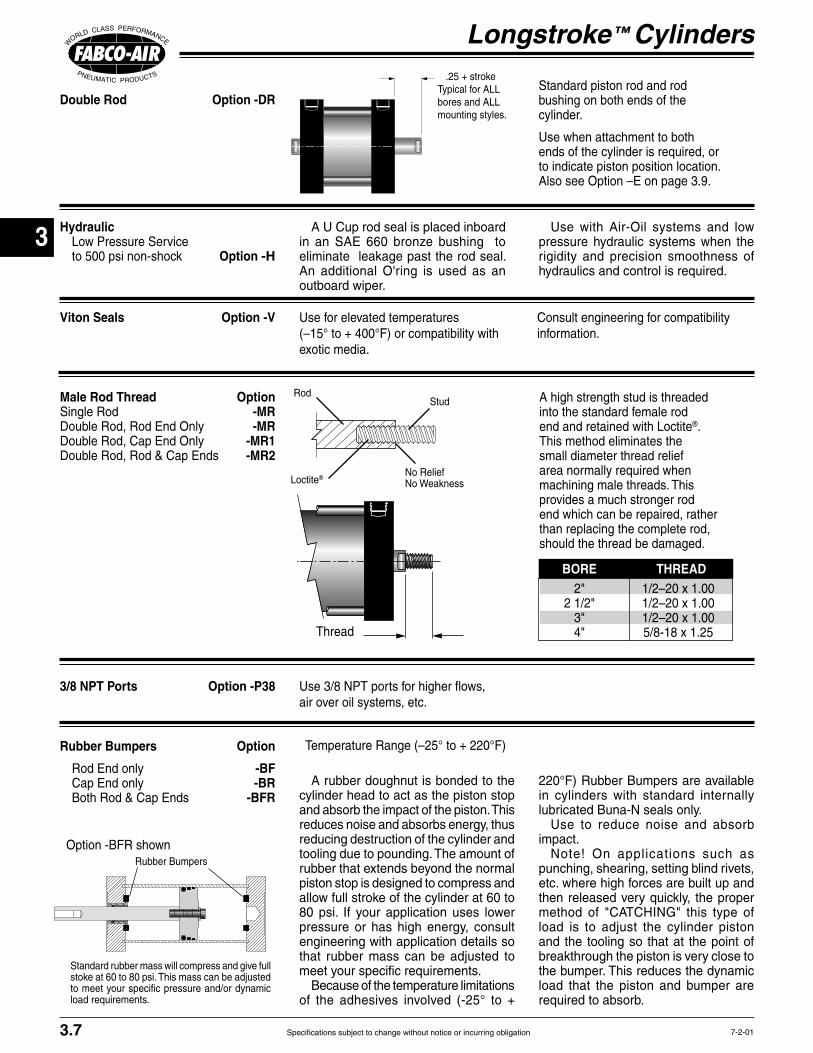
Specifications subject to change without notice or incurring obligation
3
Longstroke™ Cylinders
7-2-01
Male Rod Thread OptionSingle Rod -MRDouble Rod, Rod End Only -MRDouble Rod, Cap End Only -MR1Double Rod, Rod & Cap Ends -MR2
A high strength stud is threaded into the standard female rod end and retained with Loctite®. This method eliminates the small diameter thread relief area normally required when machining male threads. This provides a much stronger rod end which can be repaired, rather than replacing the complete rod, should the thread be damaged.
Double Rod Option -DRStandard piston rod and rod bushing on both ends of the cylinder.
Use when attachment to both ends of the cylinder is required, or to indicate piston position location. Also see Option –E on page 3.9.
Rubber Bumpers Option
Rod End only -BF Cap End only -BR Both Rod & Cap Ends -BFR
BORE THREAD
Thread
RodStud
Loctite®No ReliefNo Weakness
Hydraulic Low Pressure Service to 500 psi non-shock Option -H
A U Cup rod seal is placed inboard in an SAE 660 bronze bushing to eliminate leakage past the rod seal. An additional O'ring is used as an outboard wiper.
Use with Air-Oil systems and low pressure hydraulic systems when the rigidity and precision smoothness of hydraulics and control is required.
Viton Seals Option -V Use for elevated temperatures Consult engineering for compatibility information.
Rubber Bumpers
Option -BFR shown
Standard rubber mass will compress and give full stoke at 60 to 80 psi. This mass can be adjusted to meet your specific pressure and/or dynamic load requirements.
A rubber doughnut is bonded to the cylinder head to act as the piston stop and absorb the impact of the piston. This reduces noise and absorbs energy, thus reducing destruction of the cylinder and tooling due to pounding. The amount of
piston stop is designed to compress and allow full stroke of the cylinder at 60 to 80 psi. If your application uses lower pressure or has high energy, consult engineering with application details so that rubber mass can be adjusted to meet your specific requirements.
Because of the temperature limitations
in cylinders with standard internally lubricated Buna-N seals only.
Use to reduce noise and absorb impact.
Note! On applications such as punching, shearing, setting blind rivets, etc. where high forces are built up and then released very quickly, the proper method of "CATCHING" this type of load is to adjust the cylinder piston and the tooling so that at the point of breakthrough the piston is very close to the bumper. This reduces the dynamic load that the piston and bumper are required to absorb.
3.7
.25 + strokeTypical for ALL bores and ALL mounting styles.
3/8 NPT Ports Option -P38air over oil systems, etc.
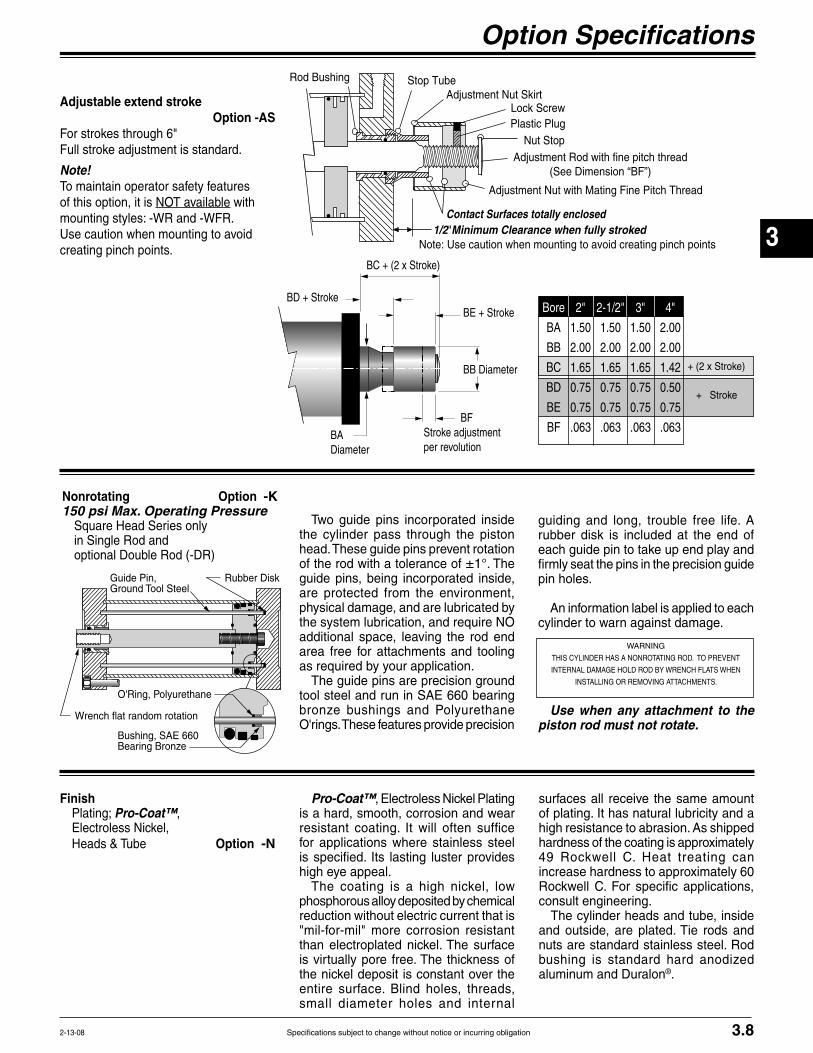
Specifications subject to change without notice or incurring obligation
3
guiding and long, trouble free life. A rubber disk is included at the end of each guide pin to take up end play and firmly seat the pins in the precision guide pin holes.
An information label is applied to each cylinder to warn against damage.
Use when any attachment to the piston rod must not rotate.
2-13-08
Option Specifications
Adjustable extend stroke Option -ASFor strokes through 6"Full stroke adjustment is standard.
Note! To maintain operator safety features of this option, it is NOT available with mounting styles: -WR and -WFR. Use caution when mounting to avoid creating pinch points.
Nut StopAdjustment Rod with fine pitch thread
Adjustment Nut with Mating Fine Pitch Thread
1/2"Minimum Clearance when fully stroked
Adjustment Nut SkirtLock ScrewPlastic Plug
Stop TubeRod Bushing
Contact Surfaces totally enclosed
Note: Use caution when mounting to avoid creating pinch points
+ Stroke
Bore 2" 2-1/2" 3" 4"
BA 1.50 1.50 1.50 2.00
BB 2.00 2.00 2.00 2.00
BC 1.65 1.65 1.65 1.42
BD 0.75 0.75 0.75 0.50
BE 0.75 0.75 0.75 0.75
BF .063 .063 .063 .063
BD + StrokeBE + Stroke
BB Diameter
BFStroke adjustmentper revolution
BADiameter
Nonrotating Option -K150 psi Max. Operating Pressure Square Head Series only in Single Rod and
Two guide pins incorporated inside the cylinder pass through the piston head. These guide pins prevent rotation of the rod with a tolerance of ±1°. The guide pins, being incorporated inside, are protected from the environment, physical damage, and are lubricated by the system lubrication, and require NO additional space, leaving the rod end area free for attachments and tooling as required by your application.
The guide pins are precision ground tool steel and run in SAE 660 bearing bronze bushings and Polyurethane O'rings. These features provide precision
Guide Pin,Ground Tool Steel
Rubber Disk
Bushing, SAE 660 Bearing Bronze
O'Ring, Polyurethane
Wrench flat random rotation
FinishPro-Coat™,
Electroless Nickel, Heads & Tube Option -N
Pro-Coat™, Electroless Nickel Plating is a hard, smooth, corrosion and wear resistant coating. It will often suffice for applications where stainless steel is specified. Its lasting luster provides high eye appeal.
The coating is a high nickel, low phosphorous alloy deposited by chemical reduction without electric current that is "mil-for-mil" more corrosion resistant than electroplated nickel. The surface is virtually pore free. The thickness of the nickel deposit is constant over the entire surface. Blind holes, threads, small diameter holes and internal
surfaces all receive the same amount of plating. It has natural lubricity and a high resistance to abrasion. As shipped
49 Rockwell C. Heat treating can
Rockwell C. For specific applications, consult engineering.
The cylinder heads and tube, inside and outside, are plated. Tie rods and nuts are standard stainless steel. Rod bushing is standard hard anodized aluminum and Duralon®.
3.8
WARNING
THIS CYLINDER HAS A NONROTATING ROD. TO PREVENT
INTERNAL DAMAGE HOLD ROD BY WRENCH FLATS WHEN
INSTALLING OR REMOVING ATTACHMENTS.

Specifications subject to change without notice or incurring obligation
3
3.9 10-23-04
Suffix Option ESpecifies Magnetic Piston
(Order Sensors and Sensor Clamps Separately)
Option -E consists of a magnet bonded into the piston head. When
activates the sensor without physical contact.
Mounting – The sensor snaps into a 2-part clamp that attaches rigidly to any of the tie rods and can be positioned anywhere along the length of the cylinder.
Reliability – The annular piston magnet is permanently bonded into a groove in the piston. It is a polarized permanent magnet of rubber bonded barium ferrite that is very stable and is not affected by shock. Under normal usage it will remain magnetized indefinitely.
Warning affect the strength of the piston magnet therefore affecting sensor
Sensor clamps and sensors are ordered separately.
Sensor
Magnet, Rubber Bonded Barium Ferrite
Tie Rod, Stainless
Steel
Cylinder HeadCylinder Tube
Piston Rod
Piston
Clamp
T
T
Sensor
Magnet, Rubber Bonded Barium Ferrite
Tie Rod, Stainless
Steel
Cylinder Head
Cylinder Tube
Piston Rod
Piston
Clamp
T
Model 521 – 6 – E shown with 2 prewired electronic sensors
Female Cordsets available in 1, 2, & 5 meter lengths
9 foot prewired sensor
2-Piece Sensor Clamp shown with quick disconnect sensor
snapped in place
Socket Head ScrewQuick DisconnectSensor Shown
WARNINGThis cylinder is equipped with a Magnetic Piston for use with Magnetically Operated Sensors. Other Magnetic Sensitive Devices Should be Kept at a Distance to Avoid Inadvertent Operation.
Sensor & Clamp Ordering Guide
Electrical CharacteristicsQuick Disconnect
Part Number.
9-2A197-13049-2A197-13339-2A197-1334
Prewired9 ft. Part No.
9-2A197-10049-2A197-10339-2A197-1034
ProductType
Reed SwitchElectronicElectronic
LED Lighted Magnetic Piston Position Sensors
For all Longstroke Models Order Part Number 800-200-000
Length 1 Meter 2 Meter 5 Meter
Part Number CFC-1M CFC-2M CFC-5M
Sensor Mounting Clamp - for all Longstroke Models
Female Cordsets for Quick Disconnect
Warning!
Permanent damage to sensor may occur.
Power supply polarity MUST be observed for proper opera-tion of sensors.
See wiring diagrams included with each sensor.
Top View Round Head Style Top View Square Head Style
Model 321 S321 521 S521 721 S721 1221 S1221
T .50" .50" .50" .10" .50" .30 .30" .30"
Sensor Clamp Stick Out Dimensions
Temperature Range
Longstroke™ Cylinders

Specifications subject to change without notice or incurring obligation
3
N L M
IJ
H
DB
C
AK
E
3.10
Kit includes:2 brackets and 4 bolts for attaching the brackets to the cylinder heads.
Material:Brackets, plated steel
Mounting Kits & Accessories
2-13-08
MaterialsBracket: High strength Zinc die castingBushings: Oil filled powdered metal
Rod Clevises
MI
J
P
E PinC
D F
L
Materials
Pin: 416 Stainless SteelClips: Steel, plated
C1.001.38
D.32.50
E PIN.3120.4995
F1.211.62
I1.311.63
Part #RC-56RC-63
J1.692.13
L.61.80
M.63.94
P Mating Eye BktEM-121EM-521
Bore2", 2-1/2", & 3"
4"
End Lug Mount Kit
AB.41.41.53.53
AH1.632.002.132.63
AO.44.44.56.56
AT.25.25.38.38
SA3.753.884.384.38
XA3.693.754.004.00
Bore2"
2-1/2"3"4"
S1.752.252.753.50
W2.503.003.504.50
Kit No.EL-20EL-25EL-30EL-40
XA + Stroke AB 6 HolesAH
AOAT SA + Stroke AO
SW1
4
2
W/2 S/23
XE1 + StrokeLH
EO1 SS1 + Stroke
TSUS
1
4
2
US/2 TS/2
3
EO1
SB 4 Holes
ST
XE2 + Stroke
LH
EO2 SS2 + Stroke
TSUS
1
4
2
US/2 TS/2
3
EO2
SB 4 Holes
ST
Position #1 Position #2
Kit includes:2 brackets and 4 bolts for attaching the brackets to the cylinder heads.
Material:Brackets, plated steel
EO10.500.500.560.56
SS12.382.633.253.25
SS22.132.131.001.00
ST.25.25.38.38
TS3.754.254.755.50
Bore2"
2-1/2"3"4"
LH1.632.002.132.63
SB.41.41.53.53
Kit No.SL-20SL-25SL-30SL-40
EO20.500.631.191.19
A2.502.002.501.50
D.36.47.58.30
E.376.501.626.3135
H.31.38.38.25
I1.131.501.630.94
Part #EM-321EM-521EM-1221EM-121
J1.692.252.631.38
K2.001.381.751.13
L0.560.751.000.44
M0.811.131.100.69
Bore2"
2-1/2", 3"4"
Rod Clevis RC-56
B2.502.002.251.50
C2.001.381.501.13
N
US4.505.005.886.63
XE13.003.133.443.44
XE22.882.882.312.31
Side Lug Mount Kit
Eye Bracket Kits mate with Option -PM or -SM and Rod Clevis
Specifications subject to change without notice or incurring obligation
4
7-5-05
Hi-Power™ Series – PageConstruction & engineering data . . . 4.2 & 4.3How to Order . . . . . . . . . . . . . . . . . . . . . . 4.4Dimensions . . . . . . . . . . . . . . . . . . . 4.5 & 4.6Option Specifications . . . . . . . . . . . 4.7 - 4.10
Multi-Power® Series –Construction & engineering data . . . 5.1 - 5.3Sizing Guide . . . . . . . . . . . . . . . . . . . . . . 5.2How to Order . . . . . . . . . . . . . . . . . . . . . . 5.4Dimensions . . . . . . . . . . . . . . . . . . . 5.5 & 5.6Option Specifications . . . . . . . . . . . 5.7 - 5.12
Pancake® Multi-Power® Series –Sizing Guide . . . . . . . . . . . . . . . . . . . . . 5.13How to Order . . . . . . . . . . . . . . . . . . . . . 5.14Dimensions . . . . . . . . . . . . . . . . . 5.13 & 5.14
Square1® Multi-Power® Series –Sizing Guide . . . . . . . . . . . . . . . . . . . . . 5.18How to Order . . . . . . . . . . . . . . . . . . . . . 5.18Dimensions . . . . . . . . . . . . . . . . . . . . . . 5.19
Longstroke™ Multi-Power® Series –Sizing Guide . . . . . . . . . . . . . . . . . . . . . 5.23How to Order . . . . . . . . . . . . . . . . . . . . . 5.23Dimensions . . . . . . . . . . . . . . . . . . . . . . 5.24
Product Index
4.1

Specifications subject to change without notice or incurring obligation
4HP Series
in relationship to stroke.
For longer strokes use THP Series below.
THP Series
in relationship to stroke.
support and longer strokes.
UHP Series
support and longer strokes.
Bore Diameter 1-1/8 1-5/8 2-1/2 3 4 5 6 8 10 12Rod Diameter 0.50 0.63 0.75 0.75 1.00 1.25 1.25 1.25 2.00 2.00Rod Area 0.20 0.31 0.44 0.44 0.79 1.23 1.23 1.23 3.1 3.1Push Area (Single Rod) 0.99 2.07 4.91 7.07 12.57 19.63 28.27 50.27 78.5 113.0Pull Area 0.79 1.76 4.47 6.63 11.78 18.40 27.04 49.04 75.4 109.9HP Base Weight, lb. 0.50 1.03 2.2 2.8 5.3 8.1 10.4 N/A N/A N/ATHP Base Weight, lb. 0.50 1.06 2.3 2.9 5.5 8.6 11.3 19.4 61.1 82.3UHP Base Weight, lb. 0.62 1.29 2.8 3.6 6.8 10.1 13.5 23.7 67.3 91.3Weight Per Inch, lb. 0.13 0.20 0.4 0.4 0.6 0.7 0.8 1.7 2.6 3.4
10-26-04
Available in 3 series10 Bore sizes 1-1/8" thru 12"Strokes to 12"
® rod bushing
piston and rod seals.
. . . . . . . . . . . . . . . . . . . . . . . . . . . . . . . . . . . . .Air . . . . . . . . . . . . . . . . . . . 250 psi
. . . . . . . . 15 psi . . . -25° to +250°F
. . . . . . . . . . . . . . ®–G Grease . . . . . . . . . . . . . . . . . . . . . . . . .
Load Capacity (psi) Machine Design 1972/73 Bearing Reference IssuePorous Bronze .............. 4,500Porous iron .................. 8,000Phenolics ..................... 6,000Nylon® ........................ 1,000TFE .............................. 500Reinforced Telfon® ..... 2,500*TFE fabric .................. 60,000Polycarbonate ............. 1,000Acetal .......................... 1,000Carbon-graphite .......... 600
* Shows Duralon bearing classification. Not to be used for design purposes.
Friction Properties Slip- Coefficient stickSteel-on-steel ................. .50 YesBronze-on-steel .............. .35 YesSintered Bronze-on-steel with mineral oil ...... .13 NoBronze-on-steel with mineral oil ....... .16 NoCopper lead alloy-on-steel .22 YesAcetal-on-steel .............. .20 NoNylon-on-steel ............... .32 YesDuralon-on-steel ............ .05 - .16 No
Duralon® Rod Bearings Excel
Printed with permission by Rexnord Corp.
Hi-Power™ Cylinders
Model THP8 x 8 - RFA shown
Ratings – Standard Units all series
Sizing Guide
4.2

Specifications subject to change without notice or incurring obligation
4
Hi-Power™ Cylinders
Cylinder OD –
The Bore ID is Hard Anodized – Hard anodizing is
-
plated steel.
An Extra Long Rod Bearing – ®
® to other com-
The Piston Rod – is Hard Chrome Plated Stainless
Piston Construction –weight. The piston rod pilot end and a pilot washer enable
Basic ConstructionStandard Models
THP Series
UHP Series
HP SeriesQuick Reference to Components
® lined Duralon® insert 7 Piston Stop
® applied and torqued
16 Stainless steel tie rods and plated steel nuts
12-15-044.3
3 15 14 344
6
7 16
7
12
5
2
11
10 13
8
1
9
3 15 14 344
6
7 16
7
12
5
2
11
10 13 17
8
1
9
3 15 14 34
4
6
7 16
7
12
5
2
11
10 18 19
8
1
9
17 18

Specifications subject to change without notice or incurring obligation
4
How to Order
6-29-05
Description Specify See Page -DR 4.10
-DR13-DR16-DR25
-K 4.10
-MR-MR -MR1-MR2
-V 4.7-H 4.10
-BF-BR-BFR
-AS 4.7
Full stroke adjustment is standard.
‡ 4.8
-TF -TR
-TFR 4.8
-P34 4.8
-E38 -E12
-E34 Port Positions 4.5 & 4.6
StandardPA2 PA3 PA4
StandardPR2 PR3 PR4
StandardPC2 PC3 PC4
as shown on pages 4.5 & 4.6‡ -E 4.9
Sensors ‡ Note: Additional Cylinder Length Required for 1/2 NPT Ports Option see page 4.8;for Option -E see page 4.9.
Model Number Code
x –3 3 FFHP
How to Order
ExamplesHP3 x 3 FF – MR
THP5 x 7 – RFA – TFR
OPTIONS
– MR
Bores Mounting Series HP, Front Face – Fabco Pattern . . . . . . . . . . .–FF THP, and . . . . .–FFA UHP . . . . . . . . . . . .–RF
. . . . . –RFA through Foot . . . . . . . . . . . . . . . . . . . . . . . . . . . . .–FT Ports in-line with slot . . . . . . . . . . . . .-PM Ports 90° to slot . . . . . . . . . . . . . . . . .-SM
. . . . . . . . . . . . . . . . . . –WF . . . . . . . . . . . . . . . . . . –WR
. . . . . . . . . . . . . –WFR
Series THP . . . . .–FFA and . . . . –RFA UHP only . . . . . . . . . . . . . . . . . . –WF
. . . . . . . . . . . . . . . . . . –WR . . . . . . . . . . . . . –WFR
SeriesHP
THPUHP
Standard Strokes
Bore
3456
345681012
4.4
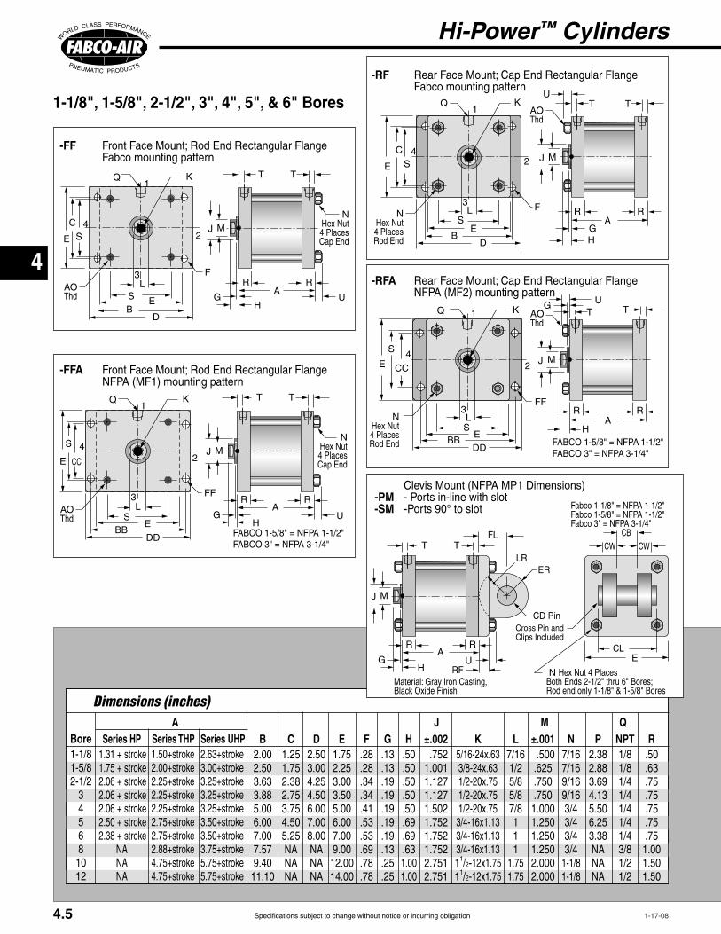
Specifications subject to change without notice or incurring obligation
4
1-17-08
Hi-Power™ Cylinders
-RF Fabco mounting pattern
T T
AGH
J
AOThd
He4 Places
Q1
2
3
4
S
S
C
D
F
-FF Fabco mounting pattern
1-1/8", 1-5/8", 2-1/2", 3", 4", 5", & 6" Bores
-RFA
T T
A
G
H
J
4 Places
AOThd
Q 1
2
3
4
S
S
CC
DD
FF
F A F A
-FFA
T T
AG
H
J
He4 Places
AOThd
Q1
2
3
4
S
CC
S
DD
FF
FF
ABore
345681012
B2.002.503.633.885.006.007.007.579.4011.10
Series HP 1.31 + stroke 1.75 + stroke 2.06 + stroke 2.06 + stroke 2.06 + stroke 2.50 + stroke 2.38 + stroke
Series THP1.50+stroke2.00+stroke2.25+stroke2.25+stroke2.25+stroke2.75+stroke2.75+stroke2.88+stroke4.75+stroke4.75+stroke
Series UHP2.63+stroke3.00+stroke3.25+stroke3.25+stroke3.25+stroke3.50+stroke3.50+stroke3.75+stroke5.75+stroke5.75+stroke
Dimensions (inches)
C1.251.752.382.753.754.505.25
D2.503.004.254.506.007.008.00
E1.752.253.003.505.006.007.009.0012.0014.00
F.28.28.34.34.41.53.53.69.78.78
G.13.13.19.19.19.19.19.13.25.25
H.50.50.50.50.50.69.69.631.001.00
J±.002 .7521.0011.1271.1271.5021.7521.7521.7522.7512.751
±.001 .500.625.750.7501.0001.2501.2501.2502.0002.000
MK
112-
112-
L
111
1.751.75
N P2.382.883.694.135.506.253.38
NPTQ
R.50.63.75.75.75.75.751.001.501.50
T T
AG
H
J
CD PinCross Pin and
He
FFF
ial: Gr
-PM - Ports in-line with slot-SM -Ports 90° to slot
4.5
T T
AG
H
J
AOThd
He4 Places
Q1
2
3
4
S
S
C
D
F

Specifications subject to change without notice or incurring obligation
4
Bore
345681012
S1.191.622.312.693.504.255.137.9010.6312.46
Dimensions (inches)
T.22.25.31.31.31.31.31.44.75.75
U.27.27.38.38.50.50.50.50.80.80
V.22.22.33.33.43.43.43.43.66.66
X.31.38.44.50.63.75.75
BB2.002.753.884.695.446.637.63
Z.44.63.56.75.881.001.00
AOW
4.565.005.81
CC1.001.432.192.763.324.104.88
DD2.503.254.505.316.387.638.63
FF.22.28.34.41.41.53.53
FO3.003.504.384.886.387.257.00
HC1.131.381.752.002.753.253.75
HT2.002.503.253.755.256.257.25
WF1.01.01.31.41.41.81.82.32.682.68
WR1.01.01.31.41.41.81.82.32.682.68
CD.500.500.500.750.750.7501.000
FL.75.75.751.251.251.251.50
RF.38.38.38.63.63.63.75
CB.76.76.761.261.261.261.51
CW.50.50.50.62.62.62.75
ER.62.62.62.87.87.871.25
LR.62.62.62.87.87.871.13
CL2.092.092.092.882.882.883.38
4-1-08
To Order
–WF–WR–WFR
-FT
XX
T T
A
GH
J
He4 Places
.25Z Z
Q 1
2
3
4
SP
S
FO
HT
HC
F
-WF-WR-WFR
VV
T T
A
GH
J
He4 Places
AOThd
Q1
2
3
4
S
S
1-1/8", 1-5/8", 2-1/2", 3", 4", 5", & 6" Bores
-ing the required length to
–WF length required
▼
8", 10", and 12" Bores
-FFA
QView 1
2
3
4
S
AO Thd
F
T T
AG
H
J He8 Places
-WF-WR-WFR
Q1
2
3
4
S V
T T
AG
H
J He8 Places
AOThd
-RFA
T T Q View1
2
3
4
S
AOThd
FAG
H
J
Tap
He8 Places
▼
Mounting Styles with Dimensions
4.6

Specifications subject to change without notice or incurring obligation
4
3-21-03
ADJUSTABLE EXTEND STROKE-AS
Full stroke adjustment is standard.Note!
with
creating pinch points.Not available for 10" & 12" bores
Dial-A-Stroke®
Note!-
machine design.The stop tube is blue anodized alu-
steel with a black anodized aluminum
with a plastic plug so that the adjust-ment nut can be locked in place without damaging the threads. The nut stop is
fine pitch threads on the adjustment rod
-
markings applied to nut skirt and stop tube.
1/2 Minimum Clearance when fully stroked
Plastic Plug
Stop Tube
Contact Surfaces totally enclosed
OPTIONVITON SEALS -V
MALE ROD THREAD-MR-MR
-MR1-MR2
strength stud is threaded into the stan-
®. This method eliminates
BORE THREAD . . . . . . . . . . . . . . . . . .
. . . . . . . . . . . . . . . . . . . . . . . . . . . . . . . . . . . . . . . . . . . . . . .
thread is machined integral with the rod.
Thread
Stroke adjustmentDiameter
+ Stroke
Hi-Power™ Cylinders
®
Stud
4.7
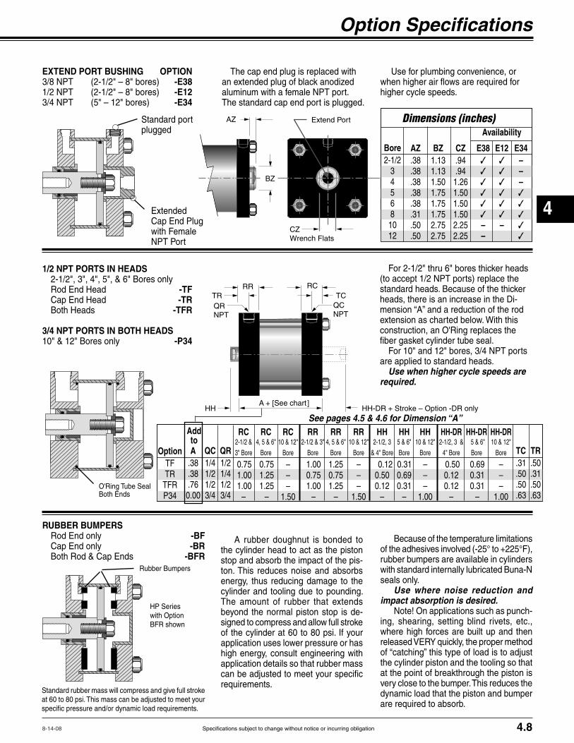
Specifications subject to change without notice or incurring obligation
4
8-14-08
Option Specifications
RUBBER BUMPERS -BF-BR
-BFR
A rubber doughnut is bonded to
-ton. This reduces noise and absorbs
-
application uses lower pressure or has
application details so that rubber mass
requirements.
Use where noise reduction and impact absorption is desired.
-
are required to absorb.
EXTEND PORT BUSHING OPTION-E38-E12-E34
The cap end plug is replaced with
The standard cap end port is plugged.
Standard port plugged
gwith Female
AZ Port
CZ
1/2 NPT PORTS IN HEADS
-TF-TR
-TFR
3/4 NPT PORTS IN BOTH HEADS -P34
-
are applied to standard heads.Use when higher cycle speeds are
required.
Bore
345681012
AZ.38.38.38.38.38.31.50.50
Dimensions (inches)
BZ1.131.131.501.751.751.752.752.75
CZ.94.941.261.501.501.502.252.25
E38✓✓✓✓✓✓––
E34–––✓✓✓✓✓
E12✓✓✓✓✓✓–
Availability
HP Serieswith Option
HH
QC
A
TC
See pages 4.5 & 4.6 for Dimension “A”
4.8
A.38.38.760.00
Add to
QC QR
RC
0.75 1.00 1.00
–
RC
0.75 1.25 1.25 –
RC
–––
1.50
RR
1.00 0.75 1.00 –
RR
1.25 0.75 1.25 –
RR
–––
1.50
HH
0.120.500.12
–
HH
0.310.690.31
–
HH
–––
1.00
OptionTF
P34
HH-DR
0.500.120.12
–
HH-DR
0.69 0.31 0.31 –
HH-DR
–––
1.00
TC.31.50.50.63
TR.50.31.50.63

Specifications subject to change without notice or incurring obligation
4
Hi-Power™ Cylinders
749 Series Sensor with Integral Clamp for 4" to 12" Bore Cylinders(shown prewired)
9-2A197 Series Sensor & Clamp for 1-1/8" to 3" Bores
Socket Head ScrewQuick Disconnect
Sensor Shown
Order Sensors and Sensor Clamps Separately
p
Piston
Ferrite
T
SensorWARNING
8", 10" & 12" Bores4" – 6" Bores
9 foot prewired sensor
Female Cordsets available in 1, 2, & 5 meter lengths
1-1/8" – 3" Bores
Sensor Clamp
Piston
T
SensorT
Option -E
Mounting – The sensor is attached to a 2-part clamp that attaches
9-2A197 Series749 Series which
with an integral clamp.
Reliability
Warning
Please note there is an increase in base length of the cylinder to accomodate the magnet. Using the table below add 'L' to Dimension 'A' on pages 4.5 & 4.6.
3-24-03
T .38 .38 .38 .38 .36 .25 .14 .10 .38 .38
.81 .75 .81 .81 .81 .75 .63 1.25 1.00 1.00 0 0 0 0 0 0 0 0 0 0
(T) Clamp Stick Out & (L) Length Adder to Dim. 'A' Pgs. 4.5 & 4.6
MAGNETIC PISTON Option -E
Sensor & Clamp Ordering Guide Warning!MUST
sensors. See wiring diagrams included with each sensor.
Length
Part No.
Length
Part No.
Temperature Range
Female Cordsets for9-2A197 Series
Quick Disconnect Sensors
Female Cordsets for 749 Series
Quick Disconnect Sensors
Product Electrical CharacteristicsQuick Discon. P/N 9-2A197-13049-2A197-13339-2A197-1334
9 ft. Prewired P/N9-2A197-10049-2A197-10339-2A197-1034
749-000-504749-000-531749-000-532
749-000-004749-000-031749-000-032
749-111-504749-111-531749-111-532
749-111-004749-111-031749-111-032
LED Lighted Magnetic Piston Position Sensors: Bores 1-1/8" – 3"
LED Lighted Magnetic Piston Position Sensors: Bores 4" – 8"
LED Lighted Magnetic Piston Position Sensors: Bores 10" & 12"
9-2A197 Series Sensor Mounting Clamps – Part Number 800-200-000
4.9
T
T
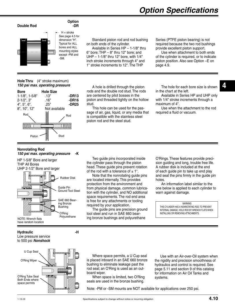
Specifications subject to change without notice or incurring obligation
4
1-18-08
Option Specifications OptionDouble Rod -DR
Nonrotating Rod150 psi max. operating pressure -K
Hole Thru 150 psi max. operating pressure
Bore Hole Size-DR13-DR16-DR25
Hydraulic -H
to 500 psi Nonshock
Standard piston rod and rod bushing required because the two rod bushings
page 4.9.
H + stroke
A hole is drilled through the piston rods and the double rod stud. The rods
stud.-
is compatible with the stainless steel piston rod and the steel stud.
space permits
Piston Stud
Two guide pins incorporated inside
-
space requirements. The rod end area
The guide pins are precision ground -
bushing to eliminate leakage past the -
board wiper.
seals are used in the bronze bushing.
-
A rubber disk is included at the end
holes.
warn against damage.Guide PinGround Tool Steel
-
4.10
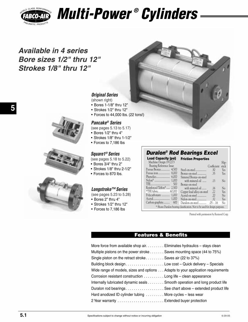
Specifications subject to change without notice or incurring obligation
5
Original Series (shown right)
Pancake® Series
Square1® Series
Available in 4 seriesBore sizes 1/2" thru 12"Strokes 1/8" thru 12"
Multi-Power ® Cylinders
Load Capacity (psi) Machine Design 1972/73 Bearing Reference IssuePorous Bronze .............. 4,500Porous iron .................. 8,000Phenolics ..................... 6,000Nylon® ........................ 1,000TFE .............................. 500Reinforced Telfon® ..... 2,500*TFE fabric .................. 60,000Polycarbonate ............. 1,000Acetal .......................... 1,000Carbon-graphite .......... 600
* Shows Duralon bearing classification. Not to be used for design purposes.
Friction Properties Slip- Coefficient stickSteel-on-steel ................. .50 YesBronze-on-steel .............. .35 YesSintered Bronze-on-steel with mineral oil ...... .13 NoBronze-on-steel with mineral oil ....... .16 NoCopper lead alloy-on-steel .22 YesAcetal-on-steel .............. .20 NoNylon-on-steel ............... .32 YesDuralon-on-steel ............ .05 - .16 No
Duralon® Rod Bearings Excel
Printed with permission by Rexnord Corp.
Longstroke™ Series
Features & Benefits
More force from available shop air Eliminates hydraulics – stays clean
Adapts to your application requirements
Corrosion resistant construction Long life – clean appearance
Internally lubricated dynamic seals Smooth operation and long product life
Duralon rod bearings See chart above – extended product life
More cycles – less wear
Extended buyer protection
5.1
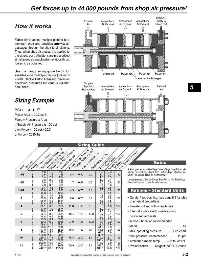
Specifications subject to change without notice or incurring obligation
5
How it works
®
of physical properties)
Air
See chart
Magnalube® –G Grease
Get forces up to 44,000 pounds from shop air pressure!
Sizing Guide
Single
Stage
Ret
ract
★
Bore
In
ches
Stages
‡
★ Areas given are for MultipleMultiple Stage Retract and any
‡ Areas given are for Standard Single Single Stage
Ratings – Standard Units
Notes
1-1/8
1-5/8
2-1/2
3
4
5
6
8
10
12
common shaft and provides internal air
simultaneously enabling tremendous thrust
operating pressures for various cylinder
Sizing Example
5.2
Shop Air Supply to Atmospheric
Air ExhaustAtmosphericAir Exhaust
AtmosphericAir Exhaust
ExhaustAir
Internal Air Passages
Piston #1Piston #2Piston #3Piston #4
ExhaustAir
AtmosphericAir Drawn In
AtmosphericAir Drawn In
AtmosphericAir Drawn In
Shop Air Supply to
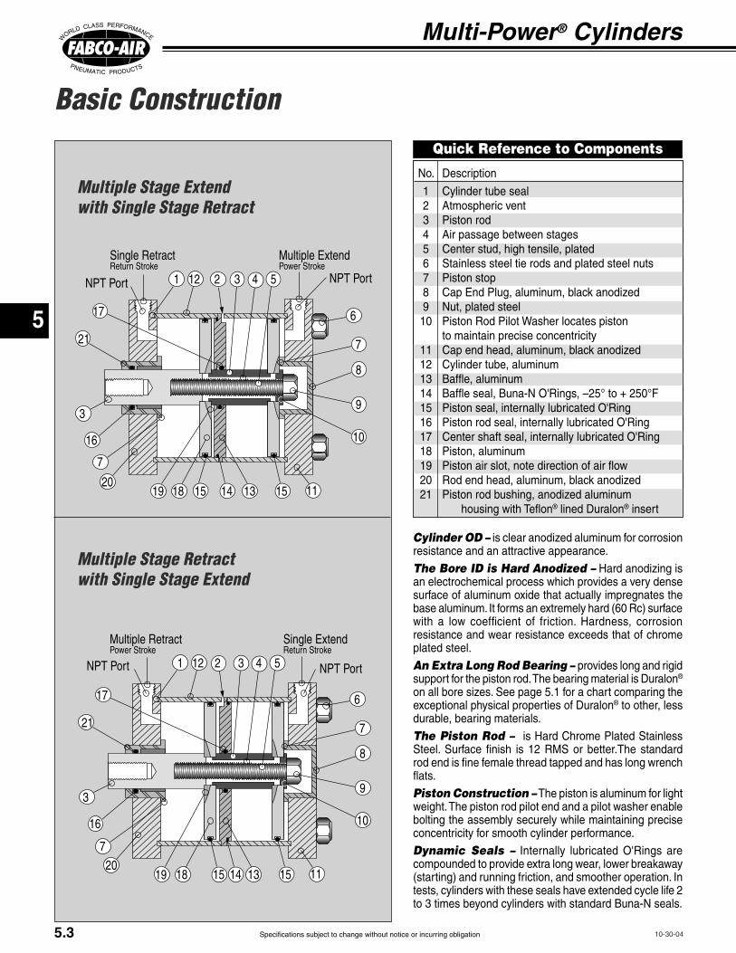
Specifications subject to change without notice or incurring obligation
5
Basic Construction
Multi-Power® Cylinders
Cylinder OD –
The Bore ID is Hard Anodized –an electrochemical process which provides a very dense surface of aluminum oxide that actually impregnates the
resistance and wear resistance exceeds that of chrome
An Extra Long Rod Bearing – provides long and rigid ®
exceptional physical properties of Duralon®
The Piston Rod –
rod end is fine female thread tapped and has long wrench
Piston Construction – The piston is aluminum for light
bolting the assembly securely while maintaining precise
Dynamic Seals –
rt
Multiple Extende
Single RetractRetur e
rt 5
rt
Single ExtendRetur e
Multiple Retracte
rt 5
Multiple Stage Retract with Single Stage Extend
Multiple Stage Extendwith Single Stage Retract
to maintain precise concentricity
® lined Duralon® insert
Quick Reference to Components
5.3

Specifications subject to change without notice or incurring obligation
5
How to Order
Description Specify See PageKF
Double Rod -DR-NR-NRDR
Single Rod -MR-MR-MR1-MR2
-V -HS
Rod End -BF Cap End -BR
-BFR-AS
Rod End Head -TF Cap End Head -TR
-TFR-P34
-E38-E12-E34-HF
-PA2-PA3-PA4
-PR2-PR3-PR4
-PC2-PC3-PC4
-PB2-PB3-PB4
Any port or vent not specified will be in
-E for reed switches and Electronic Sensors
‡ Note: Additional cylinder length required for Nonrotating Rods see page 5.8;for Option -HS see page 5.11;for 1/2 NPT Ports Option see page 5.10;for Option -E see page 5.12
OPTIONS
Model Number Code
x –1 3 – 1 FFMP3
How to Order
ExampleMP3 x 1 – 3 – 1 – FF – MR
®
MP Series& Bore
– MR
Stages Stages Extend Retract
‡
‡
‡
Standard available combinations
Multiple Extend–Multiple Retract
‡Note: Applicable only to 1-1/8" thru 8" bores.
–
StandardStrokes
OptionalStrokesany other
Bores Mounting .................................–FF
–FFA ................................. –RF
–RFA –FT
for single stage retract only–PM–SM
Extended Tie Rods
Rod end only –WF Cap end only –WR Rod and Cap Ends –WFR
–FFA –RFA –WF Cap end only –WR Rod and Cap Ends –WFR
5.4

Specifications subject to change without notice or incurring obligation
5
A= (No. stages x stroke) + y‡
Bore
5
By‡ (2 stage) y‡ (3 stage) y‡ (4 stage)
Dimensions (inches)
C D E F G HJ
±.002 ±.001M
K†
†
L N P NPTQ
R
‡ Note:
-NR, –NRDR-HS -TF, -TR, -TFR -E
† Note:
Multi-Power® Cylinders
-RF
T T
RRA
GH
MJ
U
Thd
He
Rod End
Q
LS
E
K
S
C
E
D
-FF
T T
RRA
GH
MJ
UThd
He
Cap End
Q
LS E
K
S
C
E
D
1-1/8", 1-5/8", 2-1/2", 3", 4", 5", & 6" Bores
-RFA
T T
RRA
G
H
MJ
Rod End
U
ThdQ
LS
E
K
S
CCE
DDA
A
-FFA
T T
RRA
GH
MJ
U
He
Cap End
Thd
Q
LS
E
K
S
CCE
DD
For single stage retract only
-PM-SM
T T
RRA
GH
MJ
U
ERLR
CW CW
ECL
Clips Included
HeMaterial: Gray
5.5

Specifications subject to change without notice or incurring obligation
5
Bore
5
S T U X BBZ AOW CC DD FF FO HC HT WF WRV CD FL RF CB CW ER LR CL
Mounting Styles with Dimensions
-FT
XX
T T
RR
A
GH
MJ
He
Ends
Z Z
Q
LS
K
SHT
HC
E
-WF-WR-WFR
VV
T T
RR
A
GH
MJ
He
EndsALLModels
WR
Thd
Q
LS
E
K
SE
Extended Tie Rod Mount Specify SuffixRod End only –WFCap End only –WR
–WFR
adding the required length
–WF length required
▼
1-1/8", 1-5/8", 2-1/2", 3", 4", 5", & 6" Bores
-WF-WR-WFR
Q
WL
SE
K
V
T T
RRA
GH
MJ He
Ends
WR
Thd▼
8", 10", and 12" Bores
-FFA
QRod End View
WS
E
Thd
U
T T
RRA
GH
MJ
K
He
Cap End
L
-RFA
UT T Q Cap End View
W
SE
ThdRR
AG
H
MJ
K Tap
He
Rod End
5.6
Specifications subject to change without notice or incurring obligation
5
Multi-Power® Cylinders
When required return forces (Extend or Retract) are greater than the standard
This is accomplished by replacing one
Multiple Stages Extend & Multiple Stages Retract(Not available on 10" and 12" bores)
No. of Total Available Ported No. of Combinations Baffles Stages
Notes: When any of these combinations
the extend stages are internally
Add to Dimension “A” Bore Port for each Ported Baffle
Dirty or Corrosive Environments
Applications that may dictate the use of Ported Baffles
Male Rod Thread OptionSingle Rod -MR
-MR-MR1-MR2
strength stud is threaded into the standard female rod end and retained with Loctite®
the small diameter thread relief area normally required when machining male
Thread
Rod Stud
Loctite®
t ]
Example: Model MP3x1-3-2-FF
connected for Multiple Retract
Tube seals
Atmospheric Vent
Multiple Extend
5.7
See pages 5.5 for Dimension “A”
BORE THREAD
‡
‡
Specifications subject to change without notice or incurring obligation
5
A
VCVH
HR
t ]
Atmospheric Vent for all
seal
Hex Rod
Option Specifications
Nonrotating Rod Option -NR
Nonrotating Double Rod Option -NRDR
Add to Dimension “A” 1/2 NPT Ports 3/4 NPT Ports Retract for each St'd Ports (–TF or –TFR) (–P34) Bore Port Ported Baffle HR VC VH max VC VH max VC VH max – – – –
– – – – – –– –– –– –– –
– –– –
No. of Total Available Ported No. of Combinations Baffles Stages
‡ Note: Not applicable to 10" and 12" bores
Viton Seals Option -V
Double Rod Option -DR Standard piston rod and rod bushing Use when attachment to both ends
Typical for ALL bores and ALL
Note: 10" & 12" Bores for Position Indication Only– Rod Thread 3/8-16 x 5/8 Deep
5.8
See page 5.5 for Dimension “A”
A stainless steel hex rod and a hex
assembly can be retracted by the next
normal rod head port becomes an
The hex rod design does allow for
Specifications subject to change without notice or incurring obligation
5
Adjustable extend stroke Option -AS
Note! To maintain operator safety features of this
with mounting
Not available with mounting styles -PM and -SM. Not available for 10" & 12" bores
Adjustment Rod with fine pitch thread
1/2 Minimum Clearance when fully stroked
Stop Tube
Contact Surfaces totally enclosed
® provides a rugged and
Note! Use caution when mounting to avoid creating pinch points with other parts of
is mounted on the end of the adjustment
pitch threads on the adjustment rod and nut
Rubber Bumpers Option
Rod End only -BF Cap End only -BR
-BFR
Standard rubber mass will compress and give full
Multi-Power® Cylinders
per revolutionDiameter
A rubber doughnut is bonded to the cylinder head to act as the piston stop and absorb the impact of the
The amount of rubber that extends beyond the normal piston stop is designed to compress and allow full
your application uses lower pressure or
with application details so that rubber mass can be adjusted to meet your
rubber bumpers are available in cylinders
Use where noise reduction and impact absorption is desired.
adjust the cylinder piston and the tooling
reduces the dynamic load that the piston
5.9

Specifications subject to change without notice or incurring obligation
5
Extend Port Bushing Option-E38-E12-E34
The cap end plug is replaced with an extended
1/2 NPT Ports in Heads Option
Rod End Head -TF Cap End Head -TR
-TFR
3/4 NPT Ports in BOTH Heads -P34
Standard port plugged
Extended
AZ Extend rt
CZ
Bore
5
AZ
Dimensions (inches)
BZ CZ E38 ✓✓✓✓✓–––
E34–––✓✓✓✓✓
E12✓✓✓✓✓–––
Availability
HH
QC
A ]
TCRC
TRRR
QR
High Flow Vents Option -HF
Use when higher cycle speeds are required.
Option Specifications
See pages 5.5 & 5.6 for Dimension “A”
5.10
A
Add to
QC QR
RC
ore
–
RC
–
RC
–––
RR
–
RR
–
RR
–––
HH
–
HH
–
HH
–––
Option
TR
HH-DR
–
HH-DR
–
HH-DR
–––
TC TR
Use when higher cycle speeds are required.

Specifications subject to change without notice or incurring obligation
5
Multi-Power® Cylinders
Speed & Shock ControlUsing Hydraulics Option -HS
Available with Viton seals Add -V
Note!!!All 4-Stage Units 2-1/2" thru 10" Boresare rated at 120 psi maximum air input!12" Bore, 3-Stage is rated at 130 psi max.12" Bore, 4-Stage is rated at 100 psi max.
Application Tips
Two Speed & Shock Control
rate when resistance is met and
released (such as in punching
Air supply
Directional control
® Cylinder
Sequence valve
valve
Consult your local distributor for information and product delivery
One Speed Circuit
valve give hydraulic control with
Air supply
Directional control
® Cylinder
See chart
® cylinders are applied to applications such
inertial and impact forces are often
prevent possible damage to tooling
and tube are increased in the single return stage (retract or extend) and
the material shears and the cylinder
Note!!
where high forces are built up and then
them before the cylinder reaches the
®
®
combine an automatic
Serie
s M
PM
LR, M
LS
Bore
Bore
Add to “A” Pg 5.5 & 5.6
Add to “B” Pg 5.24
5.11
Specifications subject to change without notice or incurring obligation
5
(T) Clamp Stick Out & (L) Length Adder to Dim. 'A' Pgs. 5.5 & 5.6
749 Series Sensor with Integral Clamp for 4" to 12" Bore Cylinders(shown prewired)
Option -E
Mounting rigidly to a tie rod and can be positioned anywhere along the length
9-2A197 Series749 Series which
Reliability – The annular piston magnet is permanently bonded
rubber bonded barium ferrite that is very stable and is not affected by
Warning affect the strength of the piston magnet therefore affecting sensor
Please note there is an increase in base length of the cylinder to accomodate the magnet. Using the table below add 'L' to Dimension 'A' on pages 5.5 & 5.6
9-2A197 Series Sensor & Clamp for 1-1/8" to 3" Bores
Socket Head ScrewQuick Disconnect
Sensor Shown
Magnetic Piston Option -ESpecifies Magnetic Piston
(Order Sensors and Sensor Clamps Separately)
Integral Clamp
Cylinder Head
Cylinder Tube
T
Sensor
WARNINGThis cylinder is equipped with a Magnetic
Devices Should be Kept at a Distance to
8", 10", 12" Bores4" – 6" Bores
9 foot prewired sensor
Female Cordsets available in 1, 2, & 5 meter lengths
1-1/8" – 3" Bores
Sensor Clamp
Magnet
Cylinder HeadCylinder Tube
T
SensorT
Option Specifications
Sensor & Clamp Ordering Guide Warning!MUST be observed for proper operation of
Length
Part No.
Length
Part No.
Temperature Range
Female Cordsets for9-2A197 Series
Quick Disconnect Sensors
Female Cordsets for 749 Series
Quick Disconnect Sensors
Product Reed Switch
ElectronicElectronic
Reed SwitchElectronicElectronic
Electrical Characteristics
Reed SwitchElectronicElectronic
Quick Discon. P/N 9 ft. Prewired P/N
LED Lighted Magnetic Piston Position Sensors: Bores 1-1/8" – 3"
LED Lighted Magnetic Piston Position Sensors: Bores 4" – 8"
LED Lighted Magnetic Piston Position Sensors: Bores 10" & 12"
9-2A197 Series Sensor Mounting Clamps – Part Number 800-200-000
5.12
T
T
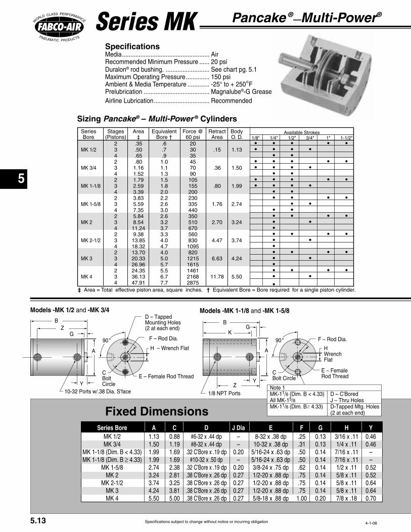
Specifications subject to change without notice or incurring obligation
5
Pancake ®—Multi-Power®
Series MK Specifications Media Air
Duralon®
Magnalube®
Airline Lubrication Recommended
Models -MK 1/2 and -MK 3/4 Models -MK 1-1/8 and -MK 1-5/8
A
°G
Z
C
Circle
D – TappedMounting Holes
Sizing Pancake® – Multi-Power ® Cylinders
‡ †
Fixed Dimensions
A C J Dia––
–
E F HGDdpdp
dp
dpdpdpdpdp
Y
––
Series Bore
≥
5.13
A H Wrench
°
G
Z
C
K
Rod Thread
5
≥J – Thru Holes

Specifications subject to change without notice or incurring obligation
5Ordering Examples
Model No: Series Bore x Stroke – Stages Extend – Stages Retract
Pancake® Multi-Power®
Pancake® Multi-Power®
How to Order
Model Number Code
x –1 3 – 1MK 1-1/8
Bore
– MR
Stages Stages Extend Retract
Standard available combinations are
Multiple Extend–Multiple Retract
StrokeSeries
Model -MK 2 Models -MK 2-1/2, -MK 3, and -MK4
A H Wrench
G
ZC
K
Rod Thread
°A H
Wrench
°
G
Z
K
Rod Thread
Stroke
MK 1/2
B Z
extend
MK 3/4
B Z B ZK Y
MK 1-1/8
B ZK
MK 1-5/8
B K Z
MK 2
B K Z
MK 2-1/2
B K Z
MK 3
B K Z
MK 4
extend
extend
Series Bore
Variable Dimensions
Suffix Options -C1 -C2 -C3
-F-F-F1-F2
Double Rod -DRMale rod thread: Single rod -MR
-MR -MR1 -MR2
Viton seals -V
for load guiding -GProCoat™ -N
-BF Cap end -BR
-BFR
-AS -PM
-SM -EPM -ESM
-E
-E38 -P14
5.14
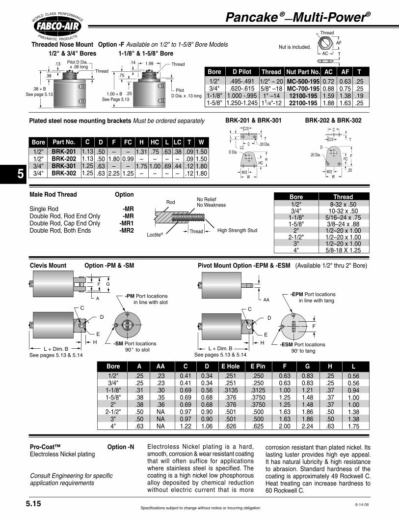
Specifications subject to change without notice or incurring obligation
5
5.15
Pancake ®—Multi-Power®
Thread
AC T
Threaded Nose Mount Option -F Available on 1/2" to 1-5/8" Bore Models
Plated steel nose mounting brackets Must be ordered separately
G
A -PM rt locations in line with slot
H -SM rt locations ° to slot
C
E
D
Clevis Mount Option -PM & -SM
AA-EPM Port locations in line with tang
H -ESM Port locations 90° to tang
C
E
D
L + Dim. BSee pages 5.13 & 5.14
F
Pivot Mount Option -EPM & -ESM
Male Rod Thread Option
Single Rod -MR-MR
-MR1-MR2
Thread
Thread
1/2" & 3/4" Bores 1-1/8" & 1-5/8" Bore
Thread
Rod
High Strength StudLoctite®
Bore Thread
Bore A FC D E Hole E Pin G HAA L
Pro-Coat™ Option -N
Consult Engineering for specific application requirements
FFC
W/2W
C
C/2
.20 Dia.
T
.25
D
BRK-202 & BRK-302
HHC
W
C
L
LC
T
BRK-201 & BRK-301
that will often suffice for applications
alloy deposited by chemical reduction without electric current that is more
Heat treating can increase hardness to
Bore ACNut Part No.MC-500-195MC-700-19512100-19522100-195
D Pilot AF TThread
Bore Part No.BRK-201BRK-202BRK-301BRK-302
C HC
–
–
H
–
–
TF–
–
D WFC–
–
L
–
–
LC
–
–

Specifications subject to change without notice or incurring obligation
5
5.16
Series MK Option Specifications
External Guide, Nonrotating
Option -G
Adjustable Extend Stroke Option -AS Available on bores 1-1/8" and larger. See description on page 5.9.
Note! Use caution when mounting to avoid creating
PP Square Guide PinsHard Chrome Steel Plated
Mounting BlockClear AnodizedAluminum
Guide BlockHard Anodized Aluminum
SSRRRR
VVMounting Holes2 Places
UUTT
JJ
LLMM
Clearance in Guide Block mounting holes allows for adjustment to compensate for wear
°
UUTT
ZZ ° °
SSRRRR
VVMounting Holes2 Places
2-1/2" through 4" Bores1-1/8" through 2" Bores
Superior nonrotating piston rod feature for
per revolutionDiameter
VV
Rubber
A donut or pad of rubber is bonded in place
reducing destruction of the cylinder and
Extend Port Bushing -E38
1/4 NPT Ports -P14
Rubber Bumpers -BF -BR -BFR Temperature Range

Specifications subject to change without notice or incurring obligation
5
5.17
Series MK Option Specifications
Sensor mounts in1/4" 60° Dovetail
Encased in plastic housing, dovetail style sensors are corrosion resistant. 60° wire outlet allows close mounting. Profile shown here is typical.
Low Profile, Solid State, Magnetic Piston Position Sensors
Length
5 Meters
Female Cordsetsfor
Quick Disconnect
Note*: Quick disconnect style sensors are supplied with 6" pigtail. Order female cordsets separately.
Electrical CharacteristicsQuick Disconnect
Part No.*Prewired 9 ft.
Part No.Sensor
TypeElectronicElectronic
LEDCylinder ModelSeries MK
Ordering Guide – Dovetail Style Magnetic Sensors
Temperature Range:
Magnetic Piston Option -E
For 1-1/8" Bore and largerIncludes Dovetail Mounting Slots
Order Sensors Separately
Double Rod Option -DR
Standard piston rod and rod bushing
Viton Seals Option -V
1/2" 3/4" 1-1/8" 1-5/8" 2" 2-1/2" 3" 4"BoreG
Shorter stroke cylinders are furnished with two dovetail mounting slots when Suffix Option "E" is specified.
A single slot on longer stroke models has room to accommodate multiple sensors.
MK1-1/8 MK1-5/8 MK4 MK3MK2-1/2MK2
° ° °°
72°
°°
45°
°°
45°
°°
45°
°°
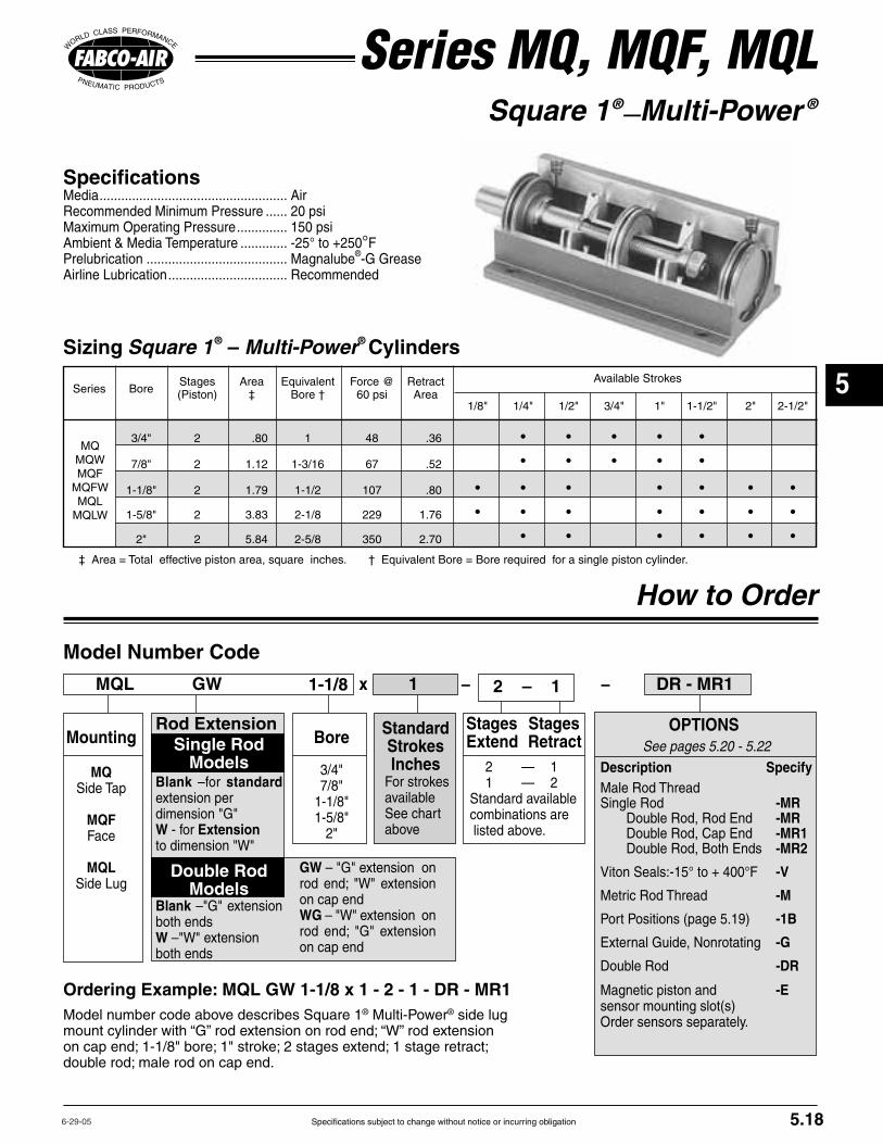
Specifications subject to change without notice or incurring obligation
5
Square 1®—Multi-Power ®
Specifications Media Air
Magnalube®
Airline Lubrication Recommended
Series MQ, MQF, MQL
Ordering Example: MQL GW 1-1/8 x 1 - 2 - 1 - DR - MR1 ® ® side lug
‡
MQMQW
MQLMQLW
Sizing Square 1® – Multi-Power® Cylinders
How to Order
OPTIONSSee pages 5.20 - 5.22
Description SpecifyMale Rod Thread Single Rod -MR
-MR-MR1-MR2
-V
Metric Rod Thread -M
-1B
-G
Double Rod -DR
Magnetic piston and -Esensor mounting slot(s)
x – 1-1/8 1 DR - MR1
Mounting
MQ Side Tap
MQF
MQLSide Lug
BoreRod Extension
Single Rod Models
Blank –for standard extension per
W Extension
Double Rod Models
Blankboth endsWboth ends
StandardStrokesInches
MQL GW
available See chart above
GW
on cap endWG
on cap end
Model Number Code
– 2 – 1
Stages Stages Extend Retract
Standard available combinations are
5.18
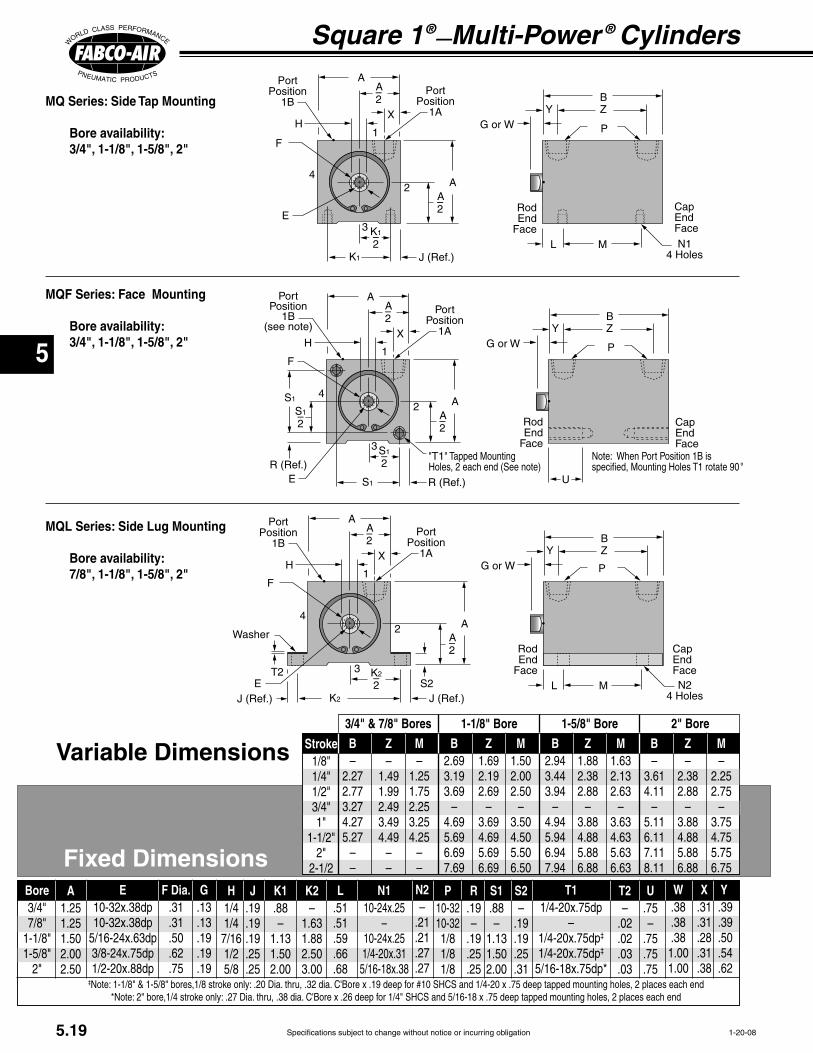
Specifications subject to change without notice or incurring obligation
5
Square 1®—Multi-Power ®
Cylinders
Variable Dimensions
Fixed Dimensions
G or W
A–A
X
U
RodEndace
S
S–
R (RefE
rt osition
(see note)
H
rt osition
A–
AS–
S
R (RefTapped Mounting
Holes
CapEnd
ace When rt
°
G or W
A–A
X
ML
RodEnd
CapEnd
K
K–
Washer
E S
H
A–
A
G or W
A–A
X
ML
RodEnd
K
K–
E
H
A–
A
CapEnd
MQ Series: Side Tap Mounting
Bore availability: 3/4", 1-1/8", 1-5/8", 2"
MQL Series: Side Lug Mounting
Bore availability: 7/8", 1-1/8", 1-5/8", 2"
B–
––
M–
––
B
–
Z
–
M
–
B
–
Z
–
M
–
B–
–
Z–
–
M–
–
Stroke
3/4" & 7/8" Bores 1-1/8" Bore 1-5/8" Bore 2" Bore
A F Dia. G H J K1
–
R
–
Bore K2–
N1
–
U
–
PN2–
S1
–
T2–
WS2–
X YE T1
–‡
‡
‡
5.19
MQF Series: Face Mounting
Bore availability: 3/4", 1-1/8", 1-5/8", 2"
Z–
––
L

Specifications subject to change without notice or incurring obligation
5
5.20
Series MQF Mounting Kits
Eye Bracket Kit
Trunnion Mount Kitc
cAL E
MountingScrews
Rod Clearance J
J
L M
IJ
H
AK
AK
E
D
C K A
IJ
E
ML
D
H
Clevis Bracket Kit
Kit No.TR-04TR-121TR-221TR-321
A B C D E F J LBore
Rod Clevises
C D E PIN F IPart #RC-19,MRC-19RC-31, MRC-31RC-38, MRC-38RC-54, MRC-54RC-56, MRC-56
J L M P English P MetricM
IJ C
D
L
Materials
Materials
Materials
Mating Eye Bracket
Rod Clevis
Clevis Bracket
Eye Bracket
A B C D E Pin F H IPart #PM-04PM-121PM-221PM-321
E Hole J K L M N
StrokeAllAllAll
BoreRod Clevis
English Metric
Rod End Cap EndClevis
BracketMating
Eye Bkt.Eye
Bracket
A D E H IPart #EM-02EM-04EM-121EM-221EM-321
J K L M N
SCS
Materials

Specifications subject to change without notice or incurring obligation
5
Square 1®—Multi-Power ®
Cylinders
External Guide, Nonrotating
Option -G Superior nonrotating piston rod feature for
ed to it which in turn pass through guide
CCCC
DD
DD__
JJ
AA Square
GG
HH
EEEE__
Mounting Holes allow foradjustment to compensate for wear
KK Mounting
E R
GSer
X
Flange Mounting Kits for Series MQF and MQFW
Flange Style 7
Bore AKit #Model Style E F FB FB2 FB4 G† R TF TF2 TF4 UF W‡ X
Port Positions
Flange Bore Fabco Mounting Hole Pattern Style Size Kit No. Interchange Information
7 3/4" H7-04
7 1-1/8" H7-121
7 1-5/8 H7-221
8 2" H8-321
9 2" H9-321
4 Hole Pattern
2 Hole Pattern
4 Hole Pattern
2 Hole Pattern
4 Hole Pattern
All brands conforming to this code2 Hole Pattern
4 Hole Pattern
All brands conforming to this code
4 Hole Pattern
Kits include Flange and 2 Flange Mounting Screws
E R
W‡
SerX
Flange Style 8 & 9
5.21

Specifications subject to change without notice or incurring obligation
5
5.22
Series MQ, MQF & MQL Option Specifications
Blank W GW
WG
G or G or W
Rod End Cap End
Double Rod Option -DR
Rod Extension Dimensions
Bore 5
G W
Dovetail style sensors are actuated
mounting slot(s) are specified with Suffix
Order sensors separately.
Magnetic Piston Option-EIncludes Dovetail Mounting Slots Order Sensors Separately
Encased in plastic housing, dovetail style sensors are corrosion resistant. 60° wire outlet allows close mounting. Profile shown here is typical.
Low Profile, Solid State, Magnetic Piston Position Sensors
Length
5 Meters
Female Cordsetsfor
Quick Disconnect
Temperature Range
Note*: Quick disconnect styles are supplied with 6 inch pigtail with male connector. Order female cordsets separately.
Electrical CharacteristicsQuick Disconnect
Part No.*Prewired 9 ft.
Part No.Sensor
Type
ElectronicElectronic
LED
Dovetail Style Magnetic Sensors
Cylinder Model
° wire outlet
Rod End
rt
MQ Profile MQF Profile MQL Profile
Male Rod Thread Option
Single Rod -MR-MR
-MR1-MR2
Bore Female Rod Thread Pitch Male Rod Thread x Length
Metric Rod Thread Option -M
St'd Inch Thread
Standard Stroke & Slot Location Guide MQ (Side Tap) MQF (Face Mount) MQL (Side Lug)
Sensor slots at
Sensor slot at
3/4" 1 1/8" 1 5/8" 2" 3/4" 1 1/8" 1 5/8" 2" 7/8" 1 1/8" 1 5/8" 2" Stroke ✓ ✓ – – ✓ ✓ – – ✓ ✓ –
✓ ✓ ✓ ✓ ✓ ✓ ✓ ✓ ✓ ✓ ✓ ✓✓ ✓ ✓ ✓ ✓ ✓ ✓ ✓ ✓ ✓ ✓ ✓✓ ✓ ✓ ✓ ✓ ✓ ✓ ✓ ✓ ✓ ✓ ✓✓ ✓ ✓ ✓ ✓ ✓ ✓ ✓ ✓ ✓ ✓ ✓✓ ✓ ✓ ✓ ✓ ✓ ✓ ✓ ✓ ✓ ✓ ✓
✓ ✓ ✓ – ✓ ✓ ✓ – ✓ ✓ ✓ ✓ ✓ ✓ – ✓ ✓ ✓ – ✓ ✓ ✓

Specifications subject to change without notice or incurring obligation
5
Series MLR & MLS How to Order
MLS3 x 3 – 2 – 1 – PM – MR
Specifications Media Air
Magnalube®
Airline Lubrication Recommended
Sizing Longstroke™ – Multi-Power® Cylinders
‡
MLR
MLS
Description SpecifyDouble Rod -DR
-NR -NRDR
Male Rod Thread Single Rod -MR
-MR-MR1-MR2
. . . . . . . . . . . . -V -HS
Rod End . . . . . . . . . . . . . . . . . . . . . -BF Cap End . . . . . . . . . . . . . . . . . . . . . -BR
. . . . . . . . . . . . . . . . . . . . . -BFR-AS -P38 -HF
Standard-PA2-PA3-PA4 Standard-PR2-PR3-PR4 Standard-PC2-PC3-PC4
Standard-PB2-PB3-PB4
Any port or vent not specified will be in
-E for reed switches and Electronic Sensors
‡ Note: Additional cylinder length required for Nonrotating Rods. . . . . . . . . . . . . . . . . 0.50"for Option -HS (see page 5.11) . . . . . . . . . 0.50"for Option -E . . . . . . . . . . . . . . . . . . . . . . . 1.00"
OPTIONS
Model Number Code
PM – MR–
MountingExtended Tie Rods Rod end only –WF Cap end only –WR Rod and Cap Ends –WFR
Clevis MountRound head only
–PM–SM
x –3 2 – 1MLR 2
Bore Stages Stages Extend Retract
Standard available combinations are listed
Multiple Extend–Multiple
StrokeSeriesMLR
Round head
MLSSquare head
–
Ordering Example
5.23
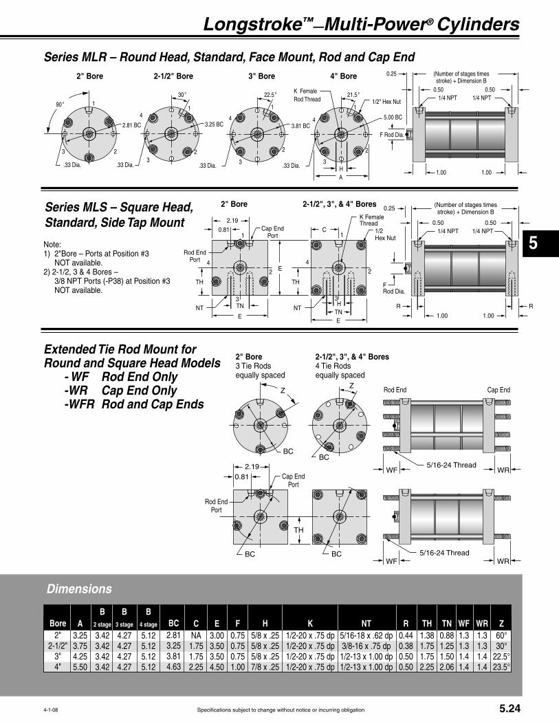
Specifications subject to change without notice or incurring obligation
5
Longstroke™—Multi-Power® Cylinders
stro
HA
° 5° 5°°
emaleRod Thread
2" Bore 4" Bore3" Bore2-1/2" Bore
Series MLR – Round Head, Standard, Face Mount, Rod and Cap End
Series MLS – Square Head,Standard, Side Tap Mount
Extended Tie Rod Mount for Round and Square Head Models - WF Rod End Only -WR Cap End Only -WFR Rod and Cap Ends
WR
Rod Endrt
TH
Cap Endrt
2-1/2", 3", & 4" BoresTie Rods
equally spaced
2" BoreTie Rods
equally spaced
Thread
Thread
ZZ
WR
Rod End Cap End
Bore WRA F K R TH TNH WFB
2 stage ECB
3 stage
B 4 stage NT ZBC
5.24
H
E
He
emaleThread
stro
C
E
Rod Endrt
R R
E
TH TH
Cap Endrt
2-1/2", 3", & 4" Bores2" Bore
Dimensions

Specifications subject to change without notice or incurring obligation
5
5.25
Longstroke™—Multi-Power ® Cylinders
EE JJ
-PM rt locations in line with slot
M -SM rt locations ° to slot
HH GG
Male Rod Thread OptionSingle Rod -MR
-MR-MR1-MR2
Double Rod Option -DR
Rubber Bumpers Option
Rod End only -BF Cap End only -BR
-BFR
A rubber doughnut is bonded to the cylinder head to act as the piston stop
reducing damage to the cylinder and
Standard rubber mass will compress
mass can be adjusted to meet your
requirements requirements
Thread
Thread
Rod
Stud
Loctite®
eTypical for all bores all mounting styles
Bore Thread
EE FF GG Pin HH JJ MBore GG HoleBRound Head Clevis Mount Option Specify mounting option Ports in line with slot -PM Ports 90° to slot -SM
Rod Clevises
Standard piston rod and rod bushing on both ends
Use when attachment to both ends of the cylinder
A high strength stud is threaded into the standard female rod end and retained with Loctite®
diameter thread relief area normally required
a much stronger rod end which can be
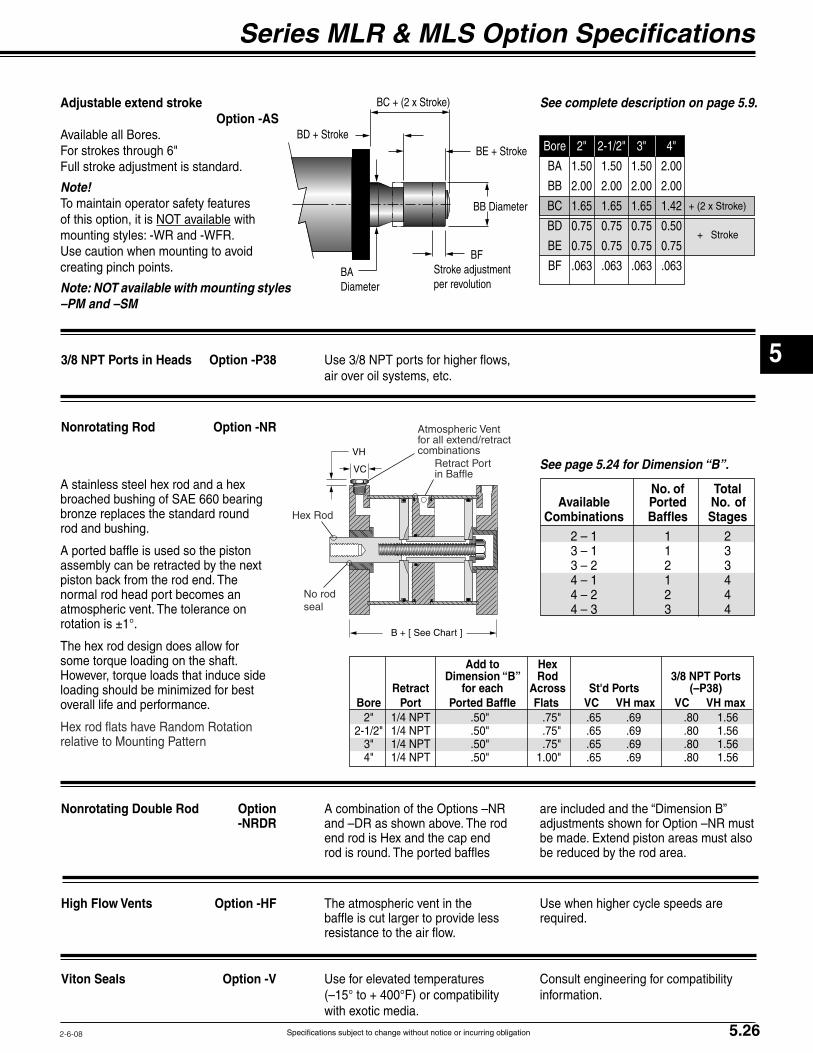
Specifications subject to change without notice or incurring obligation
5
5.26
Series MLR & MLS Option Specifications
Adjustable extend stroke Option -AS
Note! To maintain operator safety features
with
Use caution when mounting to avoid
Note: NOT available with mounting styles –PM and –SM
Nonrotating Rod Option -NR
A stainless steel hex rod and a hex
assembly can be retracted by the next
normal rod head port becomes an
The hex rod design does allow for
Nonrotating Double Rod Option -NRDR
end rod is Hex and the cap end
High Flow Vents Option -HF The atmospheric vent in the Use when higher cycle speeds are
Viton Seals Option -V Use for elevated temperatures Consult engineering for compatibility
Atmospheric Vent
combinations
seal
Hex Rod
per revolutionDiameter
3/8 NPT Ports in Heads Option -P38
No. of Total Available Ported No. of Combinations Baffles Stages
See complete description on page 5.9.
See page 5.24 for Dimension “B”.
Add to Hex Dimension “B” Rod 3/8 NPT Ports Retract for each Across St'd Ports (–P38) Bore Port Ported Baffle Flats VC VH max VC VH max
B + [ See Chart ]
VC
VH
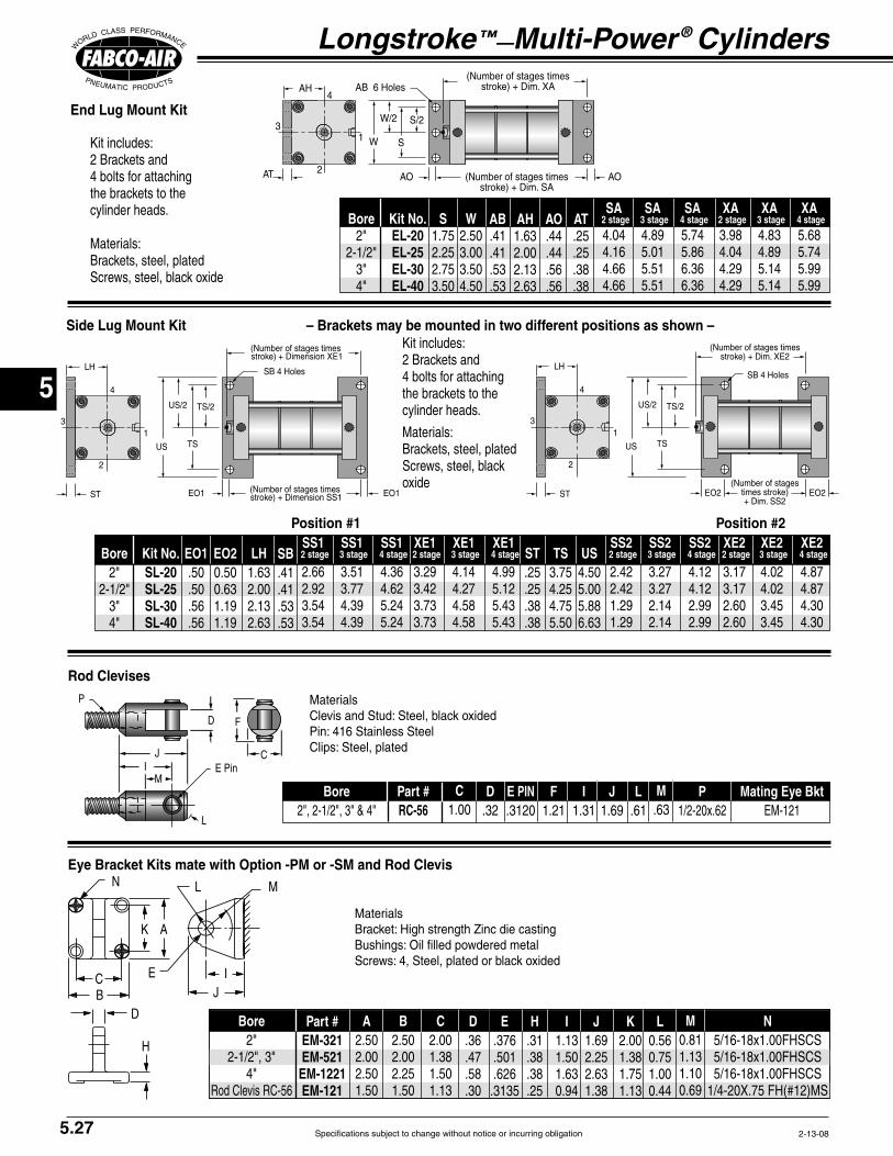
Specifications subject to change without notice or incurring obligation
5
End Lug Mount Kit
XAAH
AT SA
SWKit includes:
Materials:
stroLH
stro
TSUS
ST
stroLH
times stro )
TSUS
ST
Kit includes:
Materials:
oxide
Rod Clevises
MI
J C
D
L
Materials
Eye Bracket Kits mate with Option -PM or -SM and Rod Clevis
L M
IJ
H
C
AK
E
D
Materials
A D E H IPart #EM-321EM-521EM-1221EM-121
J K L MBore B C N
Position #1 Position #2
SBBore EO1 LHKit No.SL-20SL-25SL-30SL-40
SS1
3 stageSS1
4 stage
SS1
2 stageXE1
3 stage
XE1
4 stageXE1
2 stage
SS2 3 stage
SS2
4 stageSS2
2 stage
XE2
3 stageXE2
4 stage
XE2
2 stageST TS USEO2
C D E PIN F IPart #RC-56
J L M P Mating Eye BktBore
5.27
Side Lug Mount Kit – Brackets may be mounted in two different positions as shown –
Longstroke™—Multi-Power ® Cylinders
AB AH AO ATBore S WKit No.EL-20EL-25EL-30EL-40
XA
3 stageXA
4 stage
XA
2 stageSA
3 stage
SA
4 stageSA
2 stage

Specifications subject to change without notice or incurring obligation
5
Sensor & Clamp Ordering GuideWarning!
MUST be observed for proper operation
See wiring diagrams included
Temperature Range
Electrical CharacteristicsQuick Disconnect
Part Number.Prewired
9 ft. Part No.Product
Type
Reed SwitchElectronicElectronic
LED Lighted Magnetic Piston Position Sensors
Part Number 800-200-000
Length
Part Number
Sensor Mounting Clamp - for all MLS & MLR Models
Female Cordsets for Quick Disconnect
Series MLR & MLS Option Specifications
2-1/2" bore model shown with 2 prewired electronic sensorsand mounting clamps
Female Cordsets available in 1, 2, & 5 meter lengths
9 foot prewired sensor
snapped in place
Sensor Shown WARNING
This cylinder is equipped with a Magnetic
Devices Should be Kept at a Distance to
Suffix Option ESpecifies Magnetic Piston
(Order Sensors and Sensor Clamps Separately)
Sensor Clamp Stick Out Dimensions
Sensor
Stainless Steel
Cylinder HeadCylinder Tube
Piston Rod
Piston
Clamp
T
T
Sensor
Stainless Steel
Cylinder Head
Cylinder Tube
Piston Rod
Piston
Clamp
T
Top View Round Head Style Top View Square Head Style
5.28
Option -E
Mounting rigidly to any of the tie rods and can be positioned anywhere along
Reliability – The annular piston magnet is permanently bonded
rubber bonded barium ferrite that is very stable and is not affected by
Warning affect the strength of the piston magnet therefore affecting sensor
Please note there is an increase in base length of the cylinder to accomodate the magnet. Add 1.00" to Dimension 'B' on pages 5.24.

6
Specifications subject to change without notice or incurring obligation
BP 21/2 x 2 - FT
BA 21/2 x 2 - FT
6.1
Multi-Power® Boosters
PistonSeals
Piston
Baffle
CenterShaft
Air into MultiplePistons for Power
Stroke. 30 psi Minimum Input
PilotWasher
PistonStop
Cap EndPlug
Check ValveNot Furnished
High (Boosted) Pressure Output 500 psi Maximum
Check Valve Not Furnished
Pressurized Input to Boosterand to Reset (30 psi Minimum)
DrivingEnd
OutputEnd
Nut
Piston
AtmosphericVent
TubeSeal
BaffleSeal
PistonSeals
Piston
Baffle
CenterShaft
BaffleSeal
Air into MultiplePistons for Power
Stroke. 30 psi Minimum Input
Air into SinglePiston for Reset
Stroke
PilotWasher
PistonStop
Cap EndPlug
Check ValveNot Furnished
High (Boosted) Pressure Output 500 psi Maximum
Check Valve Not Furnished
Gravity Feed Oil or FluidAtmospheric Pressure: Air or Gas
DrivingEnd
OutputEnd
Nut
Piston
TubeSeal
8-22-01
Fabco-Air Multi-Power® Boosters provide a convenient, low cost way of adding the control, rigidity, and power of hydraulics to an air powered machine. Boosters use shop air to raise the pressure of another gas or liquid. They are compact, and versatile finding use in numerous of applications such as clamping, shearing, pressing, crimping, bending, testing, and many more.
When relatively small volumes of high-pressure fluid are called for intermittently, boosters show obvious advantages over continuously running hydraulic systems.
For applications where high pressure must be maintained for prolonged times, boosters are ideal. After the booster strokes, there is no further energy input required and no heat build up.
A booster can be mounted in almost
This series is built for use on systems in which the input to the booster will be gravity fed (no pressure) fluid or atmospheric pressure gas. It requires a 4-way air valve for operation. Porting is provided on the unit for the multiple piston power stroke and the single piston reset stroke. (See example circuits on page 6.11.)
Atmospheric Pressure Inlet to Booster: Series BA Pressurized Inlet to Booster: Series BP
any convenient location, and most of its control valves are installed in the low-pres-sure circuit where lower cost components save costs over hydraulics.
The input is shop air, or any compat-ible gas, up to 150 psi; the output can be oil, liquid, air, or gas pressurized to 500 psi maximum.
By selecting the proper combination of bore size, stroke, power factor and regulat-ing the input air pressure, the exact output pressure and required volume can be achieved and maintained.
Since it is a basic booster without controls built-in, it can be adapted and controlled to perform a wide variety of applications. Fabco-Air boosters are not limited to cylinder applications. They may be used wherever a small volume of high-pressure media is required.
This series is built for use on systems in which the input to the booster will be pressurized fluid or gas. It requires a 3-way air valve for operation. Porting is provided on the unit for the power stroke only. When power stroke air is removed, the pressurized booster input will reset the pistons. (See example circuits on page 6.9 and 6.10.)
Low initial cost: Boosters can eliminate the need for costly hydraulic systems.
Low energy cost: Boosters hold pressure indefinitely without energy loss.
Save space: Boosters can usually be
mounted directly on the machine unlike pumping units which are large and bulky.
Smooth power: Boosters give the work cylinder the rigid, smooth, controlled mo-tion of hydraulics.
Safe: Boosters can be completely air
operated to function safely in a potentially hazardous environment.
Clean: Air to air boosters have no oil or liquid to contaminate the surroundings.
Note: Check valves are not included.
(-25° to + 250°F)
booster piston
construction inch of stroke
1" increments through 6"

6
Specifications subject to change without notice or incurring obligation 6.2
How to Order1. Specify Series and Bore2. Specify Stroke3. Specify stages (Power Factor)4. Specify Mounting5. Specify Option(s)
3-19-03
Examples:BA 21/2 x 2 – 3 – FF – PA2BA Series, 21/2" Bore, 2" Stroke, 3 Stage (2.8 PF), Output End Flange Mounting, All Ports Position#2 (See page 6.6).
BP 4 x 6 – 5 – WFBP Series, 4" Bore, 6" Stroke, 5 Stage (4.8 PF), ExtendedTie Rods (Output End Only) Mounting.
Sizing Guide and How to Order
Description Specify See PageViton Seals (-15° to +400°F) -V 6.5
-BR 6.5Adjustable Extend Stroke -AS 6.6 6" Stroke maximum. Full stroke adjustment is standard.1/2 NPT Ports in Heads ‡ 6.5 Output End -TF
-TR Both Ends -TFRExtend Port Bushing 6.5 3/8 NPT Output End -EF38
-ER38 Both Ends -EFR38 1/2 NPT Output End -EF12
-ER12 Both Ends -EFR12High Flow Vents -HF 6.6Port Positions (PA2, PA3, etc.) See page 6.6 Any port or vent not specified will be in position shown on page 6.3Magnetic Piston ‡ -E 6.7 for Reed Switches and Electronic Sensors (Order Sensors separately)
-P 6.8Pneumatic Continuous Cycling -L 6.8Male Rod Thread -MR 6.8
‡ Note: Additional cylinder length required: for Option -E add 1" to driving end stage only;for 1/2 NPT Ports Option see page 6.5.
Options
Model Number Code
x2-1/2 2 FFBA
SeriesBABP
– PA2
StandardStrokes
123456
OptionalStrokes
Any other stroke through 12"
–
Bore2-1/2"
4"
Mounting
Output End Flange – Fabco Pattern . . . . . . . . . . .–FFOutput End Flange – NFPA (MF1) Pattern . . . . –FFA
. . . . . . . . . . –RF . . . . –RFA
Foot . . . . . . . . . . . . . . . . . . . . . . . . . . . . . . . .–FT
Extended Tie Rods Output End only . . . . . . . . . . . . . . . . . . –WF
. . . . . . . . . . . . . . . . . .–WR Both Ends . . . . . . . . . . . . . . . . . . . . . .–WFR
3
Stages
2
3
4
5
See Power Factor
information above
–
Sizing Guide Required Volume/Inch Required Required Number of Volume/Inch of Stroke Volume/Inch Volume/Inch Stages Theoretical of Stroke Maximum of Stroke Bore (Pistons) Power Factor In3 Gallons In3 psi In3
2 1.9 9.7 150 2-1/2 3 2.8 4.9 .021 14.5 150 4.5 4 3.7 19.3 135 5 4.6 24.1 105
2 1.9 25.1 150 4 3 2.9 12.5 .054 37.6 150 11.8 4 3.8 50.1 125 5 4.8 62.6 100
Output Input Reset Power Air Displacement Power Air for Series BA

6
Specifications subject to change without notice or incurring obligation6.3
Multi-Power® Boosters
T T
RRAAO
Thd
NHex Nut4 Places
Q 1
2
3
4
S E
S
C
E
B
F
Port Pos. 1Output End
Port Pos. 1 & 3
T T
RRA
NHex Nut4 Places
AOThd
Q 1
2
3
4
SE
S
CCE
BB
FF
Port Pos. 1Output End
Port Pos. 1 & 3
VV
T T
RR
A
NHex Nut4 PlacesBoth EndsALLModels
WF WR
AOThd
Q1
2
3
4
SE
SE
Port Pos. 1Output End
Port Pos. 1 & 3
Dimensions (inches)
3-19-03
-WF Extended Tie Rod Mount, Output End Only-WR-WFR Both Ends
-FF Front Face Mount; Output End Rectangular Flange Fabco mounting pattern
-FFA Front Face Mount; Output End Rectangular Flange NFPA (MF1) mounting pattern
Bore
2-1/2or4
Stages2345
Series BA3.914.765.616.46
Series BP3.414.265.115.96
Dimension Y‡
To order Extended Tie Rod Mount Specify SuffixOutput End Only -WF
-WRBoth Ends -WFRIf a non-standard extension is required,specify by adding the required length tothe suffix. e.g. If -WF length required is 2.5" Specify -WF2.5"
Bore2-1/2
4
B3.635.00
A‡
‡ chart above
C2.383.75
D4.256.00
E3.005.00
F.34.41
N9/163/4
P3.695.50
Q1/4 NPT1/4 NPT
R.75.75
S2.313.50
T.31.31
U.38.50
V.33.43
X.44.63
Z.56.88
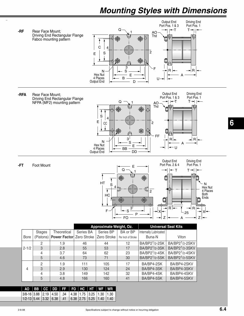
6
Specifications subject to change without notice or incurring obligation 6.4
T T
RRA
AOThd
NHex Nut4 Places
Output End
Q1
2
3
4
SE
S
C
E
B
F
Port Pos. 1Output End
Port Pos. 1 & 3
T T
RRA N
Hex Nut4 Places
Output End
AOThd
Q 1
2
3
4
SE
S
CCE
BB
FF
Port Pos. 1Output End
Port Pos. 1 & 3
XX
T T
RR
A
NHex Nut4 PlacesBoth Ends
.25Z Z
Q 1
2
3
4
SP
S
FO
HT
HC
E
F
Port Pos. 1Output End
Port Pos. 2 & 4
2-6-08
-FT Foot Mount
-RF Rear Face Mount;
Fabco mounting pattern
-RFA Rear Face Mount;
NFPA (MF2) mounting pattern
AO3/8-161/2-13
BB3.885.44
CC2.193.32
DD4.506.38
FF.34.41
FO4.386.38
HC1.752.75
HT3.255.25
WF1.301.40
WR1.301.40
Mounting Styles with Dimensions
Stages Theoretical Series BA Series BP BA or BP Internally Lubricated Bore (Pistons) Power Factor Zero Stroke Zero Stroke Per Inch of Stroke Buna-N Viton
2 1.9 46 44 12 BA/BP21/2-2SK BA/BP21/2-2SKV 2-1/2 3 2.8 55 53 17 BA/BP21/2-3SK BA/BP21/2-3SKV 4 3.7 64 62 23 BA/BP21/2-4SK BA/BP21/2-4SKV 5 4.6 73 71 30 BA/BP21/2-5SK BA/BP21/2-5SKV
2 1.9 111 105 17 BA/BP4-2SK BA/BP4-2SKV 4 3 2.9 130 124 24 BA/BP4-3SK BA/BP4-3SKV 4 3.8 149 142 32 BA/BP4-4SK BA/BP4-4SKV 5 4.8 166 160 41 BA/BP4-5SK BA/BP4-5SKV
Approximate Weight, Oz. Universal Seal Kits

6
Specifications subject to change without notice or incurring obligation
OptionViton Seals -V compatibility with exotic media. Consult engineering for
compatibility information.
Extend Port Bushing Option3/8 NPT Output End -EF38
-ER38 Both Ends -EFR381/2 NPT Output End -EF12
-ER12 Both Ends -EFR12
The end plug is replaced with an ex-tended plug of black anodized aluminum with a female NPT port. The standard end port is plugged.
AZ
BZ
3/8 or 1/2 NPT
CZWrench Flats
1/2 NPT Ports in Heads Option Output End Head -TF
-TR Both Heads -TFR
Thicker heads to accept 1/2 NPT ports, replace the standard heads. Because of the thicker heads, there is an increase in
optional rod extension as charted below. With this construction, an O-ring replaces the fiber gasket cylinder tube seal.
Use when higher cycle speeds or viscous fluids are required.
HH-P + StrokeOption -P only
QC NPT
A + See Chart
TCRC
TRRR
QR NPT
Driving End
Rubber Bumpers Option
-BR
A ring of rubber is bonded to the cylinder head, on the driving end, to act as a piston stop and absorb the impact of the piston. This reduces noise and absorbs energy.
Because of the temperature limitations of the adhesives used (-25° to +220°F), the rubber bumper is available in boosters with standard internally lubricated Buna-N seals only.
Bore2-1/2
4
AZ.38.38
Dimensions (inches)
BZ1.131.50
CZ .94 1.25
higher flows are required for higher cycle speeds and/or viscous fluids.
Also see 1/2 NPT ports in heads, Op-tions -TF, -TR, -TFR below.
Use where noise reduction and impact absorption is desired.
6.5
Multi-Power® Boosters
Option -TFR shown
Rubber Bumper
4-1-08
End
OutputEnd
EndOutput
End
Option -P Piston RodSee page 6.8
Port Bushing
One standardOutput Port Plugged Port Plugged
Port BushingOption
EndOutput
End
Option -EFR38 shown
See pages 6.3 & 6.4 for Dimension “A”
A.38.38.76
Add to
QC1/41/21/2
QR1/21/41/2
RC2-1/2" Bore
0.75 1.00 1.00
RC4"
Bore
0.75 1.25 1.25
RR2-1/2" Bore
1.00 0.75 1.00
RR4"
Bore
1.25 0.75 1.25
OptionTFTR
TFR
HH-P2-1/2 & 4" Bore
0.50 0.12 0.12
TC.31.50.50
TR.50.31.50

6
Specifications subject to change without notice or incurring obligation
Mount FT
Output Ports Specify 2&4 Standard 1&3 -PR2 1&2 -PR3 1&4 -PR4 2&3 -PR5 3&4 -PR6
8-24-01
Adjustable Extend Stroke For strokes through 6" Option -AS Full stroke adjustment is standard.
Note! To maintain operator safety features of this option, it is NOT available with mounting styles: -WR and -WFR.
creating pinch points.
® provides a rugged and precision adjustment of the ex-tend stroke of the cylinder. The stop tube, adjustment nut with skirt, and minimum clearances combine to eliminate pinch points, thus providing operator safety. Note!points with other parts of your machine design.
The stop tube is blue anodized aluminum, the adjustment nut is black-ened steel with a black anodized aluminum skirt, and the nut stop is red anodized aluminum; all for corrosion resistance and appearance. The adjustment nut, steel for long life, includes a lock screw with a plastic plug so that the adjustment nut can be locked in place without damaging the threads. The nut stop is mounted on the end of the adjustment rod so that the nut cannot come off. The fine pitch threads on the adjustment rod and nut provide precision adjustment. Adjustment settings are simplified by convenient scale markings applied to nut skirt and stop tube.
Nut Stop
Adjustment Rod with fine pitch thread
Adjustment Nut with Mating Fine Pitch Thread
1/2"Minimum Clearance when fully stroked
Adjustment Nut SkirtLock ScrewPlastic Plug
Stop TubeRod Bushing
Contact Surfaces totally enclosed
6.6
Option Specifications
High Flow Vents Option -HF The atmospheric vent in the baffle is cut larger to provide less resistance to the air flow.
Use when higher cycle speeds are required.
.75 + Stroke
.063Stroke adjustmentper revolution
1.00 + Stroke
.75 + Stroke
Port Positions Option
on pages 6.3 & 6.4)All Ports with Mounts: -FF, -FFA, -RF, -RFA, -WF, -WR, -WFR
1&3 1 1 Standard 2&4 2 2 -PA2 1&3 3 3 Rotate Standard 2&4 4 4 Rotate -PA2
All Ports with Mount -FT
2&4 1 1 Standard 1&3 2 2 -PA2 2&4 3 3 -PA3 1&3 4 4 -PA4
For all other combinations of port locations specify each port location per the chart on the right. Any port or vent not specified will be in position shown on pages 6.3 & 6.4.
Atmospheric Vent or Ported Baffle Port Specify 1 Standard 2 -PB2 3 -PB3 4 -PB4
Driving Port Specify
1 Standard 2 -PC2 3 -PC3 4 -PC4
Mounts: -FF, -FFA,
-RF, -RFA, -WF, -WR, -WFR
Output Ports Specify 1&3 Standard 2&4 -PR2 1&2 -PR3 1&4 -PR4 2&3 -PR5 3&4 -PR6
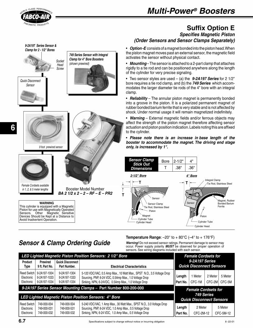
6
Specifications subject to change without notice or incurring obligation
Electrical CharacteristicsQuick Disconnect
Part Number.
9-2A197-13049-2A197-13339-2A197-1334
Prewired9 ft. Part No.
9-2A197-10049-2A197-10339-2A197-1034
ProductType
Reed SwitchElectronicElectronic
LED Lighted Magnetic Piston Position Sensors: 2 1/2" Bore
749-000-504749-000-531749-000-532
749-000-004749-000-031749-000-032
Reed SwitchElectronicElectronic
9-2A197 Series Sensor Mounting Clamps – Part Number 800-200-000
LED Lighted Magnetic Piston Position Sensors: 4" Bore
749 Series Sensor with Integral Clamp for 4" Bore Boosters(shown prewired)
Option -E consists of a magnet bonded into the piston head. When the piston magnet moves past an external sensor, the magnetic field activates the sensor without physical contact.
Mounting – The sensor is attached to a 2-part clamp that attaches rigidly to a tie rod and can be positioned anywhere along the length of the cylinder for very precise signaling.
9-2A197 Series for 2 1/2" bore requires a tie rod clamp, and (b) the 749 Series which accom-modates the larger diameter tie rods of the 4" bore with an integral clamp.
Reliability – The annular piston magnet is permanently bonded into a groove in the piston. It is a polarized permanent magnet of rubber bonded barium ferrite that is very stable and is not affected by
Warning – External magnetic fields and/or ferrous objects may affect the strength of the piston magnet therefore affecting sensor actuation and piston position indication. Labels noting this are affixed to the cylinder.
Please note there is an increase in base length of the booster to accommodate the magnet. The driving end stage only, is increased by 1".
9-2A197 Series Sensor & Clamp for 2 - 1/2" Bores
Socket Head Screw
Suffix Option ESpecifies Magnetic Piston
(Order Sensors and Sensor Clamps Separately)
Integral Clamp
Piston
Magnet, RubberBonded BariumFerrite
Tie Rod, Stainless Steel
Cylinder Head
Cylinder Tube
T
SensorWARNINGThis cylinder is equipped with a Magnetic Piston for use with Magnetically Operated Sensors. Other Magnetic Sensitive
Avoid Inadvertent Operation.
8 -22-01
Sensor & Clamp Ordering Guide Warning!occur. Power supply polarity MUST be observed for proper operation of sensors. See wiring diagrams included with each sensor.
Length 1 Meter 2 Meter 5 Meter
Part No. CFC-1M CFC-2M CFC-5M
Female Cordsets for9-2A197 Series
Quick Disconnect Sensors
Female Cordsets for 749 Series
Quick Disconnect Sensors
Length 2 Meter 5 Meter
Part No. CFC-2M-12 CFC-5M-12
4" Bore
Female Cordsets available in 1, 2, & 5 meter lengths
2-1/2" Bore
Sensor Clamp
Piston
Magnet
Tie Rod, Stainless Steel
Cylinder HeadCylinder Tube
T
SensorT
9 foot prewired sensor
Booster Model NumberBA 2 1/2 x 2 – 2 – RF – E – PR2
Quick DisconnectSensor
Temperature Range: –20° to + 80°C (–4° to + 176°F)
6.7
Multi-Power® Boosters
Bore 2-1/2" 4"
T .38" .36"
Sensor Clamp Stick Out
Dimensions

6
Specifications subject to change without notice or incurring obligation8-22-01
Option Specifications
6.8
Male Rod Thread Option -MR
A high strength stud is threaded into the standard female rod end (see Option -P above) and retained with Loctite®. This method eliminates the small diameter thread relief area normally required when machining male threads. This provides a
much stronger rod end which can be re-paired, rather than replacing the complete rod, should the thread be damaged.
Use in conjunction with Option -P above.
A piston rod is incorporated in the driv-ing end. Two limit valves are mounted on the driving end head and a piston rod guide and limit valve actuators are attached to the piston rod. The limit valves control a 3 or 4 way control valve (not included, see Section 11) which in turn controls the booster. When
strokes, raising the fluid pressure in the output end. When it fully strokes, a limit valve is actuated, reversing the booster, resetting it. When it is fully reset, the other limit valve is actuated shifting the control valve for another power stroke. This cycle continues until the output pressure reaches the desired level. The booster then stalls out and holds that pressure until some of the fluid is used. The booster then resumes cycling until output fluid again reaches desired pressure and the booster stalls out. This cycling will continue as long as
used, making the air powered booster an extremely efficient and quiet method of maintaining that high pressure. A hydraulic
power unit, for instance, requires continu-ous energy input.
Because of the piston rod, the Power Factors change slightly as shown in the chart below. A typical circuit and sizing instructions are shown in example 1 on page 6.9.
pumping action (e.g. keeping a surge tank at high pressure for a test fixture) and/or there is no electricity involved (e.g. an explosive atmosphere). Also see Option -E on page 6.7 for electronic position sen-sors.
# Stages Theoretical Bore (Pistons) Power Factor
2 1.8 2-1/2 3 2.7 4 3.6 5 4.5
2 1.9 4 3 2.8 4 3.7 5 4.7
Piston Rod on Driving End Option -P
H + Stroke
L Wrench Flats
G
K Thread
M J
AA
BB
View A–A
View B–B
Pneumatic Continuous Cycling Option -L
For details on the limit valves, which are included, see MSV-2 on page 13.5
Provisions for operator protection are always the full responsibility of the user.
A piston rod is incorporated in the driving end. Because of the piston rod area the Power Factor changes slightly.
Option -L.
Bore2-1/2
4
G.19.19
J ± .0021.1271.502
L5/87/8
H.50.50
K1/2-20 x .751/2-20 x .75
M ± .0010.7501.000
Use for booster position indication.
1.00
Stud: 1/2 - 20No reliefNo weakness
Rod
Loctite®
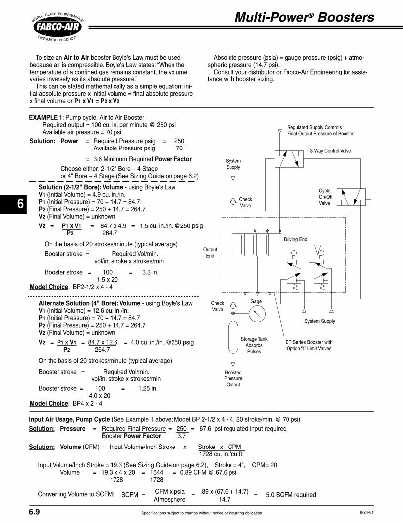
6
Specifications subject to change without notice or incurring obligation6.9
Multi-Power® Boosters
Regulated Supply ControlsFinal Output Pressure of Booster
3-Way Control Valve
Cycle On/OffValve
SystemSupply
OutputEnd
BoostedPressureOutput
GageCheckValve
Storage TankAbsorbsPulses
System Supply
BP Series Booster withOption Limit Valves
CheckValve
iving End
8-24-01
To size an Air to Air
temperature of a confined gas remains constant, the volume
This can be stated mathematically as a simple equation: ini-
x final volume or P1 x V1 = P2 x V2
-spheric pressure (14.7 psi).
Consult your distributor or Fabco-Air Engineering for assis-tance with booster sizing.
EXAMPLE 1: Pump cycle, Air to Air Booster
Input Air Usage, Pump Cycle
Solution: Power Available Pressure psig 70
Power Factor Choose either: 2-1/2" Bore – 4 Stage or 4" Bore – 4 Stage (See Sizing Guide on page 6.2)
Solution (2-1/2" Bore): VolumeV1P1P2V2
V2 P1 x V1 P2 264.7
On the basis of 20 strokes/minute (typical average)
vol/in. stroke x strokes/min
1.5 x 20 Model Choice: BP2-1/2 x 4 - 4
Alternate Solution (4" Bore): VolumeV1P1P2V2
V2 P1 x V1 P2 264.7
On the basis of 20 strokes/minute (typical average)
vol/in. stroke x strokes/min
4.0 x 20 Model Choice: BP4 x 2 - 4
Solution: Pressure Booster Power Factor 3.7
Solution: Volume 1728 cu. in./cu.ft.
1728 1728
Converting Volume to SCFM: CFM x psia .89 x (67.6 + 14.7) Atmosphere 14.7

6
Specifications subject to change without notice or incurring obligation 6.10
Air-to-Air Sizing ( for Air-to-Oil Sizing See Page 6.11)
Regulated SupplyControls FinalOutput Pressureof Booster
3 way 2 Position Valve,Cycle to Boost Input to4 way before Operating4 way to Extend Cylinders
SystemInput
CheckValve
BP Series Booster
iving EndOutput End
Gage Shows Booster Pressure
SystemInput 4 way 5 Port Valve,
2 Pressure Input,High Pressure Rating
WorkCylinders
SystemInput
4 way Control Valve
Regulated Supply
Controls FinalOutput Pressureof Booster
3 way Valve,le Pilot
BP Series Booster
iving EndOutput End
Gage Shows Booster Pressure
WorkCylinders
Sequence ValveAutomatically startsBooster when workload is reached
Pilot OperatedCheck Valve
8-24-01
EXAMPLE 2: One shot cycle, Air to Air Booster to extend cylinders with boosted (high) pressure. Application shown: 2 cylinders, 1-5/8" bore x 4" stroke must extend to full stroke at 145 psi, then retract at system (80 psi) pressure.
EXAMPLE 3: One shot cycle, Air to Air Booster to extend cylinders with low (system) pressure, then boost to high pressure.Application shown: 2 cylinders, 1-5/8" bore x 4" stroke must extend to full stroke at system (80 psi) pressure, then apply full (145 psi) clamp load. Cylinders are to retract at system (80 psi) pressure.
Alternate Solution (4" Bore): Stroke Volume/Inch Stroke‡ 12.6‡
‡
Model Choice: BP4 x 4 - 2
Solution: Power Available Pressure psig 80
Power Factor Choose either: 2-1/2" Bore – 2 Stage or 4" Bore – 2 Stage (See Sizing Guide on page 6.2)
Solution: VolumeV1P1P2V2fittings and tubingV2
V1 P2 x V2 P1 94.7Note! Add a recommended factor of 25% to 50% to allow for volumetric efficiency
Solution (2-1/2" Bore): Stroke Volume/Inch Stroke‡ 4.9‡
‡
Model Choice: BP2-1/2 x 10 - 2
Alternate Solution (4" Bore): Stroke Volume/Inch Stroke‡ 12.6‡
‡
Model Choice: BP4 x 2 - 2
Solution: Power Available Pressure psig 80
Power Factor Choose either: 2-1/2" Bore – 2 Stage or 4" Bore – 2 Stage (See Sizing Guide on Page 6.2)
Solution: VolumeV1P1P2V2fittings and tubingV2
V1 P2 x V2 P1 94.7Note! In this cycle, the volume of the cylinders and tubing may be deducted be-
Add a recommended factor of 25% to 50% to allow for volumetric efficiency and
Solution (2-1/2" Bore): Stroke Volume/Inch Stroke‡ 4.9‡
‡
Model Choice: BP2-1/2 x 4 - 2
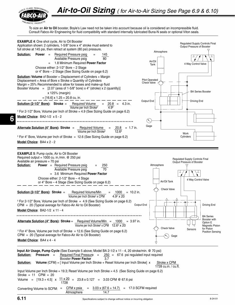
6
Specifications subject to change without notice or incurring obligation
WorkCylinders
iving EndOutput End
BA Series Booster
Regulated Supply Controls FinalOutput Pressure of Booster
Air/OilTank
Atmosphere
Gage
Pilot OperatedCheck Valve
4 Way Control Valve
Air/Oil Tank
Atmosphere
Regulated Supply Controls FinalOutput Pressure of Booster
4 Way Control Valve
Gage
iving EndOutput End
Check Valve
Check Valve
Sensors
BA Series Booster withOption EMagnetic Pistonfor PistonPosition Sensing
8-24-01
To size an Air to Oil Consult Fabco-Air Engineering for fluid compatibility with standard internally lubricated Buna-N seals or optional Viton seals.
Air-to-Oil Sizing ( for Air-to-Air Sizing See Page 6.9 & 6.10)
6.11
EXAMPLE 5: Pump cycle, Air to Oil Booster
Solution: Power Available Pressure psig 80
Power Factor Choose either: 2-1/2" Bore – 2 Stage or 4" Bore – 2 Stage (See Sizing Guide on page 6.2)
Solution: Volume
x 125% (margin)
Solution (2-1/2" Bore): Stroke Volume per Inch Stroke‡ 4.9‡
‡
Model Choice: BA2-1/2 x 5 - 2
Alternate Solution (4" Bore):
‡
Model Choice: BA4 x 2 - 2
Stroke Volume per Inch Stroke‡ 12.6‡
Solution: Power Available Pressure psig 70
Power Factor Choose either: 2-1/2" Bore – 4 Stage or 4" Bore – 4 Stage (See Sizing Guide on page 6.2)
Solution (2-1/2" Bore): Stroke Volume per Inch Stroke‡ x CPM 4.9‡ x 20‡
Model Choice: BA2-1/2 x 11 - 4
Alternate Solution (4" Bore): Stroke Volume per Inch Stroke‡ x CPM 12.6‡ x 20‡
Model Choice: BA4 x 4 - 4
EXAMPLE 4: One shot cycle, Air to Oil BoosterApplication shown: 2 cylinders, 1-5/8" bore x 4" stroke must extend tofull stroke at 145 psi, then retract at system (80 psi) pressure.
Input Air Usage, Pump Cycle
Atmosphere 14.7
Solution: Pressure Booster Power Factor 3.7Solution: Volume 1728 cu.in. / cu.ft.
11 x 20 1728
Converting Volume to SCFM:
6
Specifications subject to change without notice or incurring obligation
Cylinders, Valves, & Accessories
Notes

9
Air-Oil Tanks
Specifications subject to change without notice or incurring obligation
Features and Benefits Operation to 150 psi
direction control systems
bottom heads
10-26-049.1
Single Tank UnitsDouble Tank Units Features & Benefits
Portw Port
Port
wPort
onebeloplate rsediment tosettle out
plates &spacers &bottom
Custom molded
seal
acedisturbance
oaming
UsableOil
Capacity
Translucent
tube
Air-Oil System Notes1
2
3
4
5 -
-
-
-
Single Tank Units
Single Tank Units
Double Tank Units
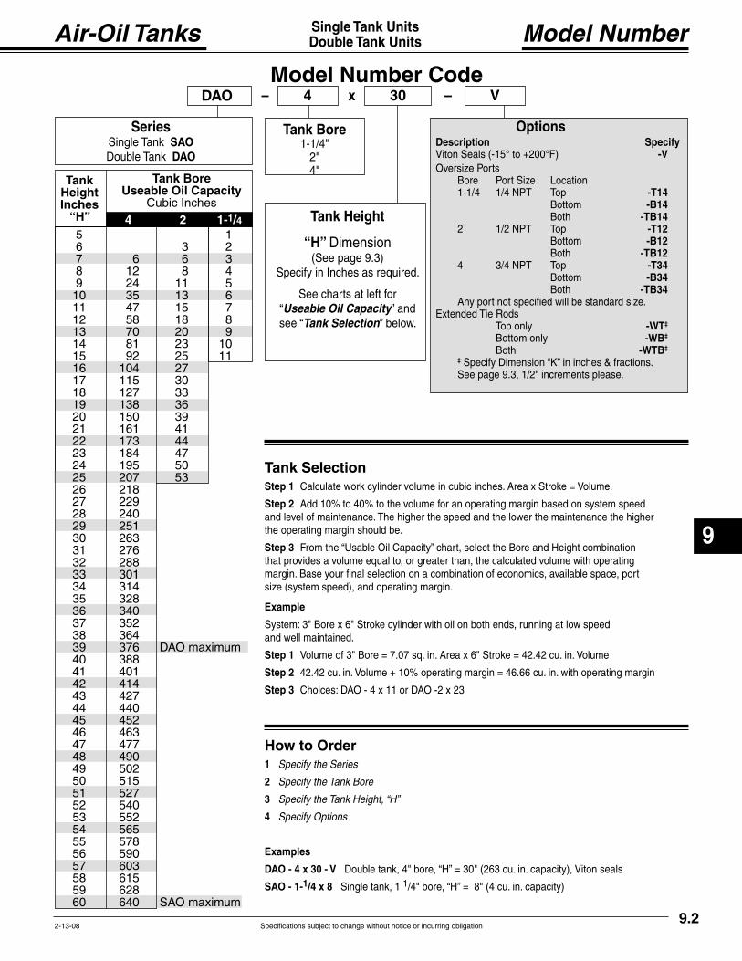
Air-Oil Tanks
9
Specifications subject to change without notice or incurring obligation2-13-089.2
Single Tank UnitsDouble Tank Units Model Number
Description Specify -V
-T14-B14
-TB14-T12-B12
-TB12-T34-B34
-TB34
Top only -WT‡
-WB‡
-WTB‡
‡
Options
Model Number CodexDAO – 4 30 V–
SeriesSingle Tank SAO
DAO
Tank Height
“H”
Useable Oil CapacityTank Selection
Tank Bore
TankHeightInches
“H”
Tank Bore Useable Oil Capacity
Cubic Inches
Tank SelectionStep 1
Step 2
Step 3
Example
Step 1
Step 2
Step 3
How to Order1 Specify the Series
2 Specify the Tank Bore
3 Specify the Tank Height, “H”
4 Specify Options
Examples
DAO - 4 x 30 - V
SAO - 1-1/4 x 8 1
4 2 1-1/4 5 1 6 3 2
8 12 8 4 9 24 11 5 10 35 13 6
12 58 18 8
14 81 23 10 15 92 25 11
19 138 36 20 150 39 21 161 41
24 195 50
26 218
28 240 29 251 30 263
32 288 33 301 34 314 35 328 36 340
38 364
40 388 41 401 42 414
44 440 45 452 46 463
48 490 49 502 50 515
52 540 53 552 54 565
56 590
58 615 59 628
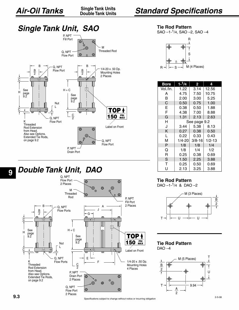
9
Air-Oil Tanks
Specifications subject to change without notice or incurring obligation2-5-089.3
Single Tank UnitsDouble Tank Units Standard Specifications
w Ports__2
C
A
C
Threaded
Also see Options
Seepage
w Ports
Port2 Places
w Port2 Places
Port2 Places
w Port2 Places
MThreaded
C__2
C
Seepage
4 Places
JG
E
TOP150 PSI
MAX
ront
w Port__2
C
__2
C
Threaded
Also see Options
Seepage
w Port
Port
w Port
Port
w Port
M
C__2
C
Seepage
ront
2 Places
TOP150 PSI
MAX
S
T U
__2
U
T
U
TA__2
__2
Single Tank Unit, SAO
Tie Rod Pattern1 4
Tie Rod Pattern
Tie Rod Pattern1 4
Double Tank Unit, DAO
Bore 1-1/4 2 4
See page

Air-Oil Tanks
9
Specifications subject to change without notice or incurring obligation4-12-04 9.4
Single Tank UnitsDouble Tank Units Typical Circuits
Cylinder
SingleTankUnit
Air Supply
wControl
V e 4-Way
Cylinder
leAir - OilTanks
Air Supply
V e 4-Way
wControl
Crosso r
pro
tank le els
SingleAir - Oil
Tank
Air Supply
Cylinder
V e 4-Way r
-1Sequence V e
or details
2-Way - Oil
V e
One Speed
® Cylinder and Multi-Power®
Two Speed Two Speed & Shock Control
Two Speed Stop & Hold
1
2
Can be used for Multi-Power® Cylinder and Multi-Power® Air Press with Option -HS. See page 5.4 and catalog # FP16.
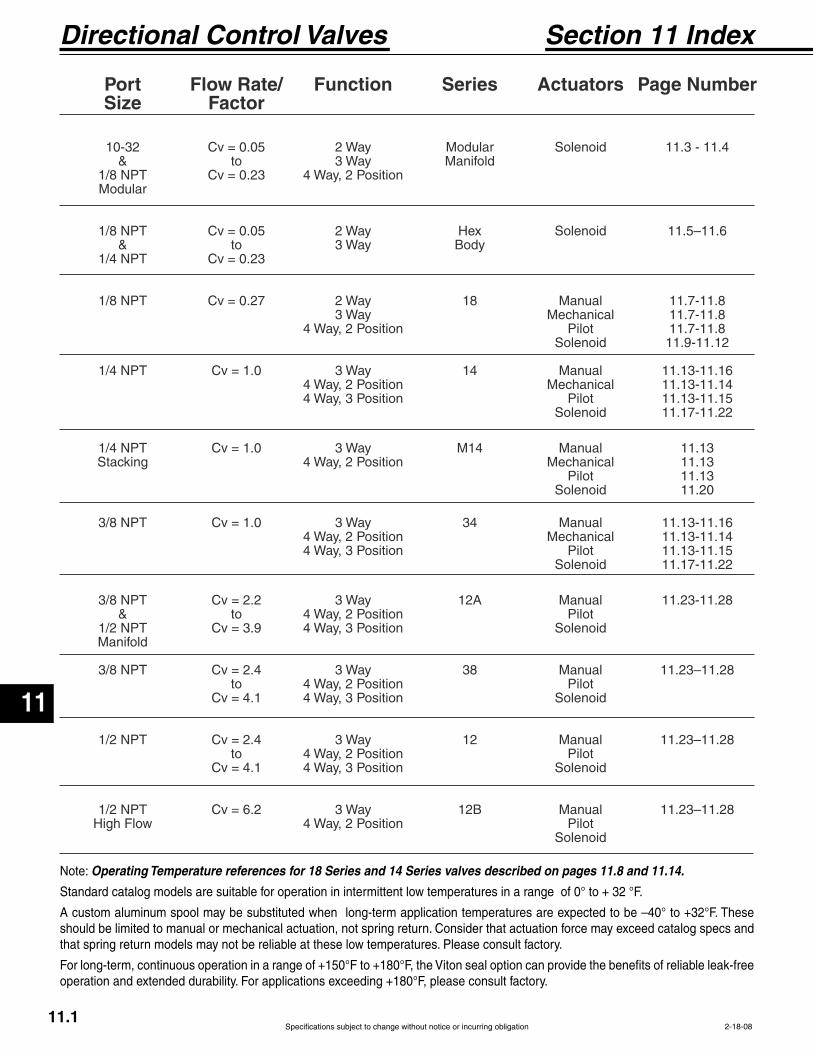
Specifications subject to change without notice or incurring obligation
Directional Control Valves
11
11.12-18-08
Port Flow Rate/ Function Series Actuators Page Number Size Factor
10-32 Cv = 0.05 2 Way Modular Solenoid 11.3 - 11.4 & to 3 Way Manifold 1/8 NPT Cv = 0.23 4 Way, 2 Position Modular
1/8 NPT Cv = 0.05 2 Way Hex Solenoid 11.5–11.6 & to 3 Way Body 1/4 NPT Cv = 0.23
1/8 NPT Cv = 0.27 2 Way 18 Manual 11.7-11.8 3 Way Mechanical 11.7-11.8 4 Way, 2 Position Pilot 11.7-11.8 Solenoid 11.9-11.12
1/4 NPT Cv = 1.0 3 Way 14 Manual 11.13-11.16 4 Way, 2 Position Mechanical 11.13-11.14 4 Way, 3 Position Pilot 11.13-11.15 Solenoid 11.17-11.22
1/4 NPT Cv = 1.0 3 Way M14 Manual 11.13 Stacking 4 Way, 2 Position Mechanical 11.13 Pilot 11.13 Solenoid 11.20
3/8 NPT Cv = 1.0 3 Way 34 Manual 11.13-11.16 4 Way, 2 Position Mechanical 11.13-11.14 4 Way, 3 Position Pilot 11.13-11.15 Solenoid 11.17-11.22
3/8 NPT Cv = 2.2 3 Way 12A Manual 11.23-11.28 & to 4 Way, 2 Position Pilot 1/2 NPT Cv = 3.9 4 Way, 3 Position Solenoid Manifold
3/8 NPT Cv = 2.4 3 Way 38 Manual 11.23–11.28 to 4 Way, 2 Position Pilot Cv = 4.1 4 Way, 3 Position Solenoid
1/2 NPT Cv = 2.4 3 Way 12 Manual 11.23–11.28 to 4 Way, 2 Position Pilot Cv = 4.1 4 Way, 3 Position Solenoid
1/2 NPT Cv = 6.2 3 Way 12B Manual 11.23–11.28 High Flow 4 Way, 2 Position Pilot Solenoid
Section 11 Index
Note: Operating Temperature references for 18 Series and 14 Series valves described on pages 11.8 and 11.14.
Standard catalog models are suitable for operation in intermittent low temperatures in a range of 0° to + 32 °F.
A custom aluminum spool may be substituted when long-term application temperatures are expected to be –40° to +32°F. These should be limited to manual or mechanical actuation, not spring return. Consider that actuation force may exceed catalog specs and that spring return models may not be reliable at these low temperatures. Please consult factory.
For long-term, continuous operation in a range of +150°F to +180°F, the Viton seal option can provide the benefits of reliable leak-free operation and extended durability. For applications exceeding +180°F, please consult factory.
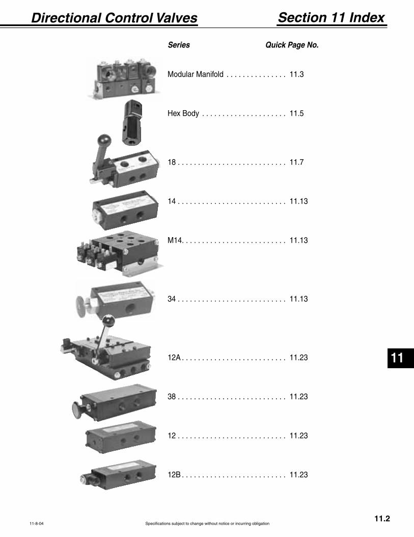
Specifications subject to change without notice or incurring obligation
11
Directional Control Valves
11.2
Section 11 Index
Series Quick Page No.
Modular Manifold . . . . . . . . . . . . . . . 11.3
Hex Body . . . . . . . . . . . . . . . . . . . . . 11.5
18 . . . . . . . . . . . . . . . . . . . . . . . . . . . 11.7
14 . . . . . . . . . . . . . . . . . . . . . . . . . . . 11.13
M14. . . . . . . . . . . . . . . . . . . . . . . . . . 11.13
34 . . . . . . . . . . . . . . . . . . . . . . . . . . . 11.13
12A . . . . . . . . . . . . . . . . . . . . . . . . . . 11.23
38 . . . . . . . . . . . . . . . . . . . . . . . . . . . 11.23
12 . . . . . . . . . . . . . . . . . . . . . . . . . . . 11.23
12B . . . . . . . . . . . . . . . . . . . . . . . . . . 11.23
11-8-04

Specifications subject to change without notice or incurring obligation
Directional Control Valves
11
Modular Manifold10-32 & 1/8 NPT
2, 3 & 4 Way
12-22-06
Miniature 53 STYLE Solenoid Valves2, 3 or 4 Way - Modular Manifolding
2, 3 or 4 Way - Single Mounting
Valves with 10-32 or 1/8 NPT ports are available in singular or modular manifold versions. Any combination of function and ports can be combined in the same manifold stack to save time, space and plumbing. With pressure manifold plugging, two or more pressure ranges and/or medias can be controlled in the same stack.
Banks
Example… Using the photo above1 Bank consisting of: 1 113-M-C-1 120/60 1 103-M-F-1 120/60 1 104-M-G-1 120/60 1 114-M-C-1 120/60
Applies to all 4 Way 104 and 114 series valves.See Orifice Information below for pressure ranges of 2 & 3 Way valves.
STANDARD SPRING 40 psi Minimium
See Orifice Information below for Maximum with other orifices.
OPTIONAL LOW PRESSURE SPRING20 psi: 20 psi Minimum 25 psi Maximum25 psi: 25 psi Minimum 60 psi Maximum
Inlet Cylinder Basic Function Port Port Model No.
Valves for 2 Way N.C. 1/8 NPT 1/8 NPT 112-SIndividual 3 Way N.C. 1/8 NPT 1/8 NPT 113-SMounting & 4 Way 10-32 10-32 104-S-10Individual 4 Way 1/8 NPT 10-32 104-S-18Inlet 4 Way 1/8 NPT 1/8 NPT 114-S
Valves for 2 Way N.C. 10-32 10-32 102-SMModular 3 Way N.C. 10-32 10-32 103-SMMounting &Individual Inlet
Valves for 2 Way N.C. 1/8 NPT 10-32 102-MModular 2 Way N.C. 1/8 NPT 1/8 NPT 112-MMounting & 3 Way N.C. 1/8 NPT 10-32 103-MManifolded 3 Way N.C. 1/8 NPT 1/8 NPT 113-M
All Mountings 3 Way Normally Open use 4 Way & Plug N.C. port
OPTION INFORMATION
ORIFICE INFORMATION
-VCoils & Housing, See page 11.29.
-N, See page 1.10.
Use 4 Way Valve & Plug N.C. Port.
Accessories
CFM – Flow @
Number 0 1/32 .022 500 psi 200 psi 150 psi 1.3 0.9 Number 1 3/64 .055 400 150 150 3.5 2.0 Number 2 1/16 .075 200 100 100 5.8 3.4 Number 3 3/32 .156 100 60 80 9.0 6.0 Number 4 1/8 .230 75 30 Not Available Not Available 8.0
Available Orifices and Equivalent Maximum PressureRatings for AC Voltages (DC Ratings Slightly Lower)
EXAMPLEBasic Model Number 103-M See Chart Below
-C C Conduit, G Grommet, F Number for Seat -1 See orifice information chart belowOptions See option Information belowVolts & Hertz 120/60 See solenoid information Page11.29
: 3 Way modular mounting with manifold inlet, 1/8 NPT inlet,10-32 Cylinder Port, Conduit Housing, 3/64 Seat, 120 Volts/60 HZ.Model Number = 103-M-C-1, 120/60
11.3
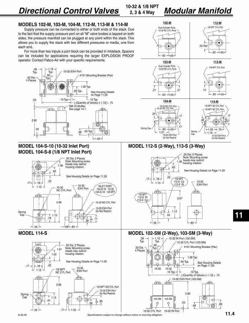
Specifications subject to change without notice or incurring obligation
11
Directional Control Valves Modular Manifold10-32 & 1/8 NPT
2, 3 & 4 Way
8-26-04
on Page 11.29
1.13Typ.
.38Typ.
Valv 5
.56Typ.
1.38 Typ.
.83 Typ.
.19 Typ..19 Typ.
10-32 EXH Port
SM-10 Muffler,See page 14.1.
.25
.03.68
ke
2.80
.55 Typ.
1.02
4 Places
.55.83
PortsPorts
102-M
.55.83
PortsPorts
103-M
.21.21
.55.83
Port
104-M
.17.24
Port
.17
1.2110-32 EXH Port
rict
Spring Cap
.55.83
Port
112-M
.
.55.83
Port
113-M
.10
.791.19
Port
114-M
.25
SpringCap
Port
.17
1.02
.36
10-32 EXH Portrict
1.38
.22
.83
1.13.78.17
2.68
1.13.78
2 Places.Note: Mounting screwheads may restrict housing rotation.
age 11.29
SpringCap
10-32 Port
10-32 EXH Port
.71.55.38
.83.38.56
Port
10-32 EXH Portrict
T104-S-10 10-32
104-S-18 1/8 NPT
1.81
.22
1.02
1.13.78.17
2.68
1.13.91
2 Places.Note: Mounting screwheads may restrict housing rotation.
age 11.29
SpringCap
1/8 NPT Port
10-32 EXH Port
.80.55.38
1.02.17.56
Port10-32 EXH Port
rict
1.38
.22
.83
1.13.78.17
2.67
1.13.55
2 Places. Note: Mounting screwheads may restrict housing rotation.
age 11.29
10-32 EXH Port
.83.56
1/8 NPT112-S Cyl113-S IN
1/8 NPT112-S IN113-S Cyl
on Page 11.29
102-SM 103-SM
1.13Typ.
.38Typ.
Valv 5
.56Typ.
1.38 Typ.
.83 Typ.
.19 Typ..19 Typ.10-32 10-32
10-32 IN PortPort
Port 10-32 IN Port
10-32 EXH Port
2.80
.03 .89.68
ke4 Places
MODEL 114-S
MODELS 102-M, 103-M, 104-M, 112-M, 113-M & 114-M
sides, the pressure manifold can be plugged at any point within the stack. This allows you to supply the stack with two different pressures or media, one from each end.
For more than two inputs a port block can be provided in midstack. Spacers
operator. Contact Fabco-Air with your specific requirements.
MODEL 102-SM (2-Way), 103-SM (3-Way)
MODEL 104-S-10 (10-32 Inlet Port)MODEL 104-S-8 (1/8 NPT Inlet Port)
MODEL 112-S (2-Way), 113-S (3-Way)
11.4
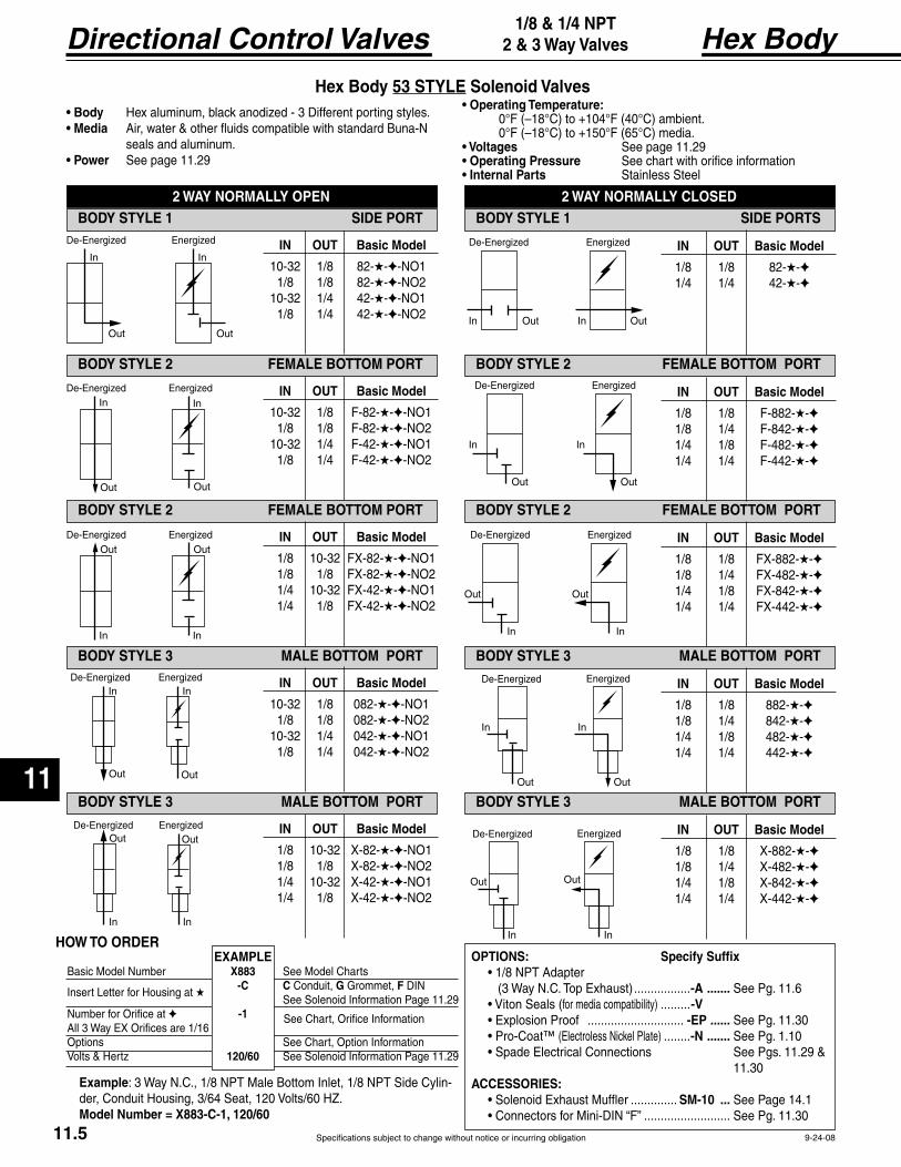
Specifications subject to change without notice or incurring obligation
Directional Control Valves
11
IN OUT Basic Model
1/8 10-32 X-82-★-✦-NO1 1/8 1/8 X-82-★-✦-NO2 1/4 10-32 X-42-★-✦-NO1 1/4 1/8 X-42-★-✦-NO2
IN OUT Basic Model
1/8 1/8 X-882-★-✦ 1/8 1/4 X-482-★-✦ 1/4 1/8 X-842-★-✦ 1/4 1/4 X-442-★-✦
Hex Body1/8 & 1/4 NPT
2 & 3 Way Valves
9-24-08
In
Out
In
Out
ed Energized
In
Out
In
Out
ed Energized
In
Out
In
Outed Energized
In
Out
In
Out
ed Energized
In
Out
In
Outed Energized
In Out In Out
ed Energized
Out
In
Out
In
De-Energized Energized
In
Out
In
Out
ed Energized
In
Out
In
Out
ed Energized
Hex Body 53 STYLE Solenoid Valves
IN OUT Basic Model
10-32 1/8 82-★-✦-NO1 1/8 1/8 82-★-✦-NO2 10-32 1/4 42-★-✦-NO1 1/8 1/4 42-★-✦-NO2
2 WAY NORMALLY OPENBODY STYLE 1 SIDE PORT
2 WAY NORMALLY CLOSEDBODY STYLE 1 SIDE PORTS
BODY STYLE 2 FEMALE BOTTOM PORT BODY STYLE 2 FEMALE BOTTOM PORT
BODY STYLE 2 FEMALE BOTTOM PORT BODY STYLE 2 FEMALE BOTTOM PORT
BODY STYLE 3 MALE BOTTOM PORT BODY STYLE 3 MALE BOTTOM PORT
BODY STYLE 3 MALE BOTTOM PORT BODY STYLE 3 MALE BOTTOM PORT
IN OUT Basic Model
1/8 1/8 82-★-✦ 1/4 1/4 42-★-✦
IN OUT Basic Model
10-32 1/8 F-82-★-✦-NO1 1/8 1/8 F-82-★-✦-NO2 10-32 1/4 F-42-★-✦-NO1 1/8 1/4 F-42-★-✦-NO2
IN OUT Basic Model
1/8 1/8 F-882-★-✦ 1/8 1/4 F-842-★-✦ 1/4 1/8 F-482-★-✦ 1/4 1/4 F-442-★-✦
IN OUT Basic Model
1/8 10-32 FX-82-★-✦-NO1 1/8 1/8 FX-82-★-✦-NO2 1/4 10-32 FX-42-★-✦-NO1 1/4 1/8 FX-42-★-✦-NO2
IN OUT Basic Model
1/8 1/8 FX-882-★-✦ 1/8 1/4 FX-482-★-✦ 1/4 1/8 FX-842-★-✦ 1/4 1/4 FX-442-★-✦
IN OUT Basic Model
10-32 1/8 082-★-✦-NO1 1/8 1/8 082-★-✦-NO2 10-32 1/4 042-★-✦-NO1 1/8 1/4 042-★-✦-NO2
IN OUT Basic Model
1/8 1/8 882-★-✦ 1/8 1/4 842-★-✦ 1/4 1/8 482-★-✦ 1/4 1/4 442-★-✦
.................-A ....... See Pg. 11.6 .........-V
............................. -EP ...... See Pg. 11.30 ........-N ....... See Pg. 1.10
11.30
.............. SM-10 ... See Page 14.1 .......................... See Pg. 11.30
seals and aluminum. See page 11.29
See page 11.29 See chart with orifice information
Stainless Steel
HOW TO ORDER
★
See Chart, Orifice Information
EXAMPLEBasic Model Number X883 See Model Charts -C C Conduit, G Grommet, F See Solenoid Information Page 11.29Number for Orifice at ✦ -1 All 3 Way EX Orifices are 1/16Options See Chart, Option Information Volts & Hertz 120/60 See Solenoid Information Page 11.29
: 3 Way N.C., 1/8 NPT Male Bottom Inlet, 1/8 NPT Side Cylin-der, Conduit Housing, 3/64 Seat, 120 Volts/60 HZ.Model Number = X883-C-1, 120/60
11.5
In
Out
In
Out
ed Energized
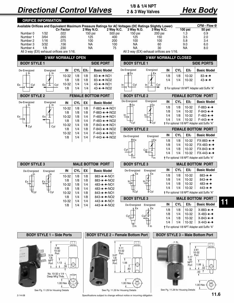
Specifications subject to change without notice or incurring obligation
11
Directional Control Valves
IN CYL EX† Basic Model
1/8 1/8 10-32 X-883-★-✦ 1/8 1/4 10-32 X-483-★-✦ 1/4 1/8 10-32 X-843-★-✦ 1/4 1/4 10-32 X-443-★-✦
†
IN CYL EX† Basic Model
1/8 1/8 10-32 883-★-✦ 1/8 1/4 10-32 843-★-✦ 1/4 1/8 10-32 483-★-✦ 1/4 1/4 10-32 443-★-✦
†
IN CYL EX† Basic Model
1/8 1/8 10-32 FX-883-★-✦ 1/8 1/4 10-32 FX-483-★-✦ 1/4 1/8 10-32 FX-843-★-✦ 1/4 1/4 10-32 FX-443-★-✦
†
IN CYL EX Basic Model
10-32 1/8 1/8 883-★-✦-NO1 1/8 1/8 1/8 883-★-✦-NO2 10-32 1/8 1/4 483-★-✦-NO1 1/8 1/8 1/4 483-★-✦-NO2 10-32 1/4 1/8 843-★-✦-NO1 1/8 1/4 1/8 843-★-✦-NO2 10-32 1/4 1/4 443-★-✦-NO1 1/8 1/4 1/4 443-★-✦-NO2
Hex Body1/8 & 1/4 NPT
2 & 3 Way Valves
2-14-08
3.241/8
NPTPort
2.6810-32Port
1.13.39
.73
1.00 Hex
No. 10-32 x 1/4Thds.
3.671/8
NPTPort
3.1110-32Port
1.56
.83
1.00 Hex
3.171/8
NPTPort
2.6110-32Port
1.06.33
1.00 Hex
.50
In
Cyl
In
Cyl
ed Energized
Ex Ex
In
Cyl
In
Cyl
ed Energized
Ex Ex
In
Cyl
In
Cyl
ed Energized
Ex Ex
In Cyl In Cyl
Exed Energized
Ex
In
Cyl
In
Cyl
ed EnergizedEx Ex
In
Cyl Cyl
In
ed EnergizedEx Ex
In
Cyl
In
Cyl
ed EnergizedEx Ex
In
Cyl
In
Cyl
ed EnergizedEx Ex
ORIFICE INFORMATIONAvailable Orifices and Equivalent Maximum Pressure Ratings for AC Voltages (DC Ratings Slightly Lower) CFM – Flow @
Number 0 1/32 .022 150 psi 500 psi 150 psi 200 psi 1.3 0.9 Number 1 3/64 .055 125 400 125 150 3.5 2.0 Number 2 1/16 .075 100 200 100 100 5.8 3.4 Number 3 3/32 .156 NA 100 NA 60 9.0 6.0 Number 4 1/8 .230 NA 75 NA 30 NA 8.0
3 WAY NORMALLY OPENBODY STYLE 1 SIDE PORT
3 WAY NORMALLY CLOSEDBODY STYLE 1 SIDE PORTS
IN CYL EX† Basic Model
10-32 1/8 1/8 83-★-✦-NO1 1/8 1/8 1/8 83-★-✦-NO2 10-32 1/4 1/4 43-★-✦-NO1 1/8 1/4 1/4 43-★-✦-NO2
BODY STYLE 2 FEMALE BOTTOM PORT BODY STYLE 2 FEMALE BOTTOM PORT
IN CYL EX Basic Model
10-32 1/8 1/8 F-883-★-✦-NO1 1/8 1/8 1/8 F-883-★-✦-NO2 10-32 1/8 1/4 F-483-★-✦-NO1 1/8 1/8 1/4 F-483-★-✦-NO2 10-32 1/4 1/8 F-843-★-✦-NO1 1/8 1/4 1/8 F-843-★-✦-NO2 10-32 1/4 1/4 F-443-★-✦-NO1 1/8 1/4 1/4 F-443-★-✦-NO2
IN CYL EX† Basic Model
1/8 1/8 10-32 F-883-★-✦ 1/8 1/4 10-32 F-843-★-✦ 1/4 1/8 10-32 F-483-★-✦ 1/4 1/4 10-32 F-443-★-✦
BODY STYLE 2 FEMALE BOTTOM PORT
BODY STYLE 3 MALE BOTTOM PORT
BODY STYLE 3 MALE BOTTOM PORT
BODY STYLE 3 MALE BOTTOM PORT
IN CYL EX† Basic Model
1/8 1/8 10-32 83-★-✦ 1/4 1/4 10-32 43-★-✦
†
†
BODY STYLE 1 – Side Ports BODY STYLE 2 – Female Bottom Port BODY STYLE 3 – Male Bottom Port
11.6

Specifications subject to change without notice or incurring obligation
Directional Control Valves
11
18 Series1/8 NPT
2, 3 & 4 Way
1-26-08
1/8 NPT Standard.10-32 = Option -E
Pilot Bushing
ingHousing 9/16 Hex
9/16 Hex
.13
.38
1.25
1.63
1/8 NPT Standard.10-32 = Option -E
.78
.50
.25 Stroke
.13
.1.88
.25 Stroke
.13.88
Standard 2 Way & 3 Way spring return are normally closed. For normally open the actuators may be exchanged end for end or by speci-fying -20 for -2 & -30 for -3.Minimum pilot pressure: Standard spring . . . . . . . . . 60 psi
-L . . . 40 psi . . . . . . . . . . . . 20 psi
2 Way 3 Way 4 Way
18SP-2 18SP-3 18SP-4
1800-902 1800-903 1800-904
-L10-32 pilot port, Option -E
Air Pilot
Roller Cam
Rod Actuator
meets low pressure requirements.Standard 2 Way & 3 Way spring return are normally closed. For nor-mally open the actuators may be exchanged end for end or by specifying -20 for -2 & -30 for -3.Minimum pilot pressure: Standard spring . . . . . . . . . 10 psi
-L . . . . 7 psi Against 0 psi pilot . . . . . . . . 2 psi
2 Way 3 Way 4 Way
18SA-2 18SA-3 18SA-4
When both pilots are pressurized, the amplifier overrides.
1800-902 1800-903 1800-904
-L10-32 pilot port, Option -E
Stainless steel rod in brass bushing. Standard 2 Way & 3 Way spring return are normally closed. For normally open the actuators may be exchanged end for end or specify by substituting -20 for -2 & -30 for -3.Force to actuate: Standard spring . . . . . . . . . 6.5 lb.
-L . . . 5.0 lb. . . . . . . . . . . . . 1.2 lb.
2 Way 3 Way 4 Way
1800-902 1800-903 1800-904
-L
Case hardened steel roller and shaft in hard anodized aluminum housing. Standard 2 Way & 3 Way spring return are normally closed. For normally open specify by substituting -20 for -2 & -30 for -3.Force to actuate: Standard spring . . . . . . . . . 6.5 lb.
-L . . . 5.0 lb. . . . . . . . . . . . . 1.2 lb.
2 Way 3 Way 4 Way
1800-912 1800-913 1800-914
1800-922 1800-923 1800-924
-L
1
212 10
12 10
21.13
1.31
.16
.811.44
1.81
Clearancef
.381.00
1.25
Primary Secondary
2 WAY31
2
12 10
3 Way
This 3 Way Valve maybe used for any 3 Way,
erterservice.
12 10
21.13
1.44
.16
.811.58
2.02
Clearancef
.381.00
1.25
Primary Secondary
3
1.34.63
3 1
214 12
5
4
4 Way - 5 Port ‡
14 12
2
1.52
1.44
.16
1.201.97
2.41
Clearancef
.38
1.25
Primary Secondary
3
1.73.63
5
4
.89.67
1.00
1/8 NPT PORTED, MANUAL, MECHANICAL AND PILOT OPERATED AIR VALVES – “The Finest in Simplicity”
Suitable for Vacuum directional flow applications, but NOT for holding vacuum.® spools provides fast, positive, and reliable response.
Valve Body Dimensions
Note 1: Specify Normally Open by substituting -20 for -2 & -30 for -3.
Standard 2 & 3 way spring return models are normally closed. Models with thread in actuators may be converted to normally open by exchanging actuators end for end. Other models require specification and factory assembly. See note 1.
May be used as either single inlet - dual exhaust or dual inlet - single exhaust.
11.7

Specifications subject to change without notice or incurring obligation
11
Directional Control Valves®–G Grease
Solenoid controlled models +150°F max. See pages 11.9 and 11.11.
18 Series1/8 NPT
2, 3 & 4 Way
2-7-08
.75.97
.50
.25 Stroke
1.25
.91
.50
.25 Stroke
1.38 .811.65
.50
3/4-16.25 Stroke
x x .13 thick brass nuts included
1.00
16°
1.50
Leverposition when spring returned
3.38
.75 Dia.
Palm ButtonAssembly
No. 1800-1No. 1800-2 Small Button
Panel Mount Button Assembly
No. 1800-7-2 1800-7-20 1800-7-3 1800-7-30 Above NOT interchangeable End for End 1800-7-4
1800-8
Rod ActuatorAssembly
No. 1800-3
Assembly
No. 1800-4 No. 1800-5 Standard Spring onlyNo. 1800-46 -L).No. 1800-56 Standard Spring & Housing Assembly.
MOST THREADED-IN OPERATORS ARE INTERCHANGEABLE BETWEEN ENDSPilot Bushing
No. 1800-10 10-32 PortNo. 1800-18 1/8 NPT Port
Un-anodized aluminum button with stainless steel rod in brass bush-ing. Standard 2 Way & 3 Way spring return are normally closed. For normally open the actuators may be exchanged end for end or specify by substituting -20 for -2 & -30 for -3.Force to actuate: Standard spring . . . . . . . . . 6.5 lb.
-L . . . 5.0 lb. . . . . . . . . . . 1.2 lb.
2 Way 3 Way 4 Way
18PS-2 18PS-3 18PS-4
18PSP-2 18PSP-3 18PSP-4
18PPS-2 18PPS-3 18PPS-4
1800-902 1800-903 1800-904
-L
Small Palm Button
Large Palm Button
Hand Lever
Panel Mount Button
stainless steel rod in brass bush-ing. Standard 2 Way & 3 Way spring return are normally closed. For normally open the actuators may be exchanged end for end or specify by substituting -20 for -2 & -30 for -3.Force to actuate: Standard spring . . . . . . . . . 6.5 lb.
-L . . . 5.0 lb. . . . . . . . . . . 1.2 lb.
Phenolic button with plated steel rod black button stan-
dard, red button Option -R. Standard 2 Way and 3 Way assemblies are
position. For normally open specify by substituting -20 for -2 and -30 for -3.Force to actuate: Standard spring . . . . . . . . . 6.5 lb.
-L . . . 5.0 lb. . . . . . . . . . . 1.2 lb.
. . . . . . . . . . . . . . 3.0 lb.
1/8 NPT Standard
No. 18 AMP-1 1/8 NPT PortNo. 10 AMP-1 10-32 Port Option -E
Fabco-Air has the expertise and willingness to design. modify and adapt these valves to your necessary and specific job requirements. Please ad-vise us of your needs.
Hardened & plated steel shaft with unique connection to spool results in positive shifting. Standard 2 Way & 3 Way spring return are normally closed. For normally open specify by substituting -20 for -2 & -30 for -3. Force to actuate: Standard spring . . . . . . . . . 4.0 lb.
-L . . . 3.0 lb. . . . . . . . . . . . . . . 2.0 lb.
Aluminum bar body
single inlet - dual exhaust or dual inlet - single exhaust.
2 Way 3 Way 4 Way
1800-902 1800-903 1800-904
-L
2 Way 3 Way 4 Way
18PMS-2 18PMS-3 18PMS-4
18PMP-2 18PMP-3 18PMP-4
1800-902 1800-903 1800-904
1800-942† 1800-943† 1800-944† -L
2 Way 3 Way 4 Way
1800-932† 1800-933† 1800-934†† Includes factory assembled spool attachments.
-L
FEATURES OPTIONS-L
Viton seals – Specify Option -V
common inlet. Consult factory.
Note 1: Specify Normally Open by substituting -20 for -2 & -30 for -3.
11.8
OPERATING TEMPERATURE FOOTNOTE SEE PAGE 11.1

Specifications subject to change without notice or incurring obligation
Directional Control Valves
11
18 Series1/8 NPT
2, 3 & 4 Way
2-14-08
1/8 NPT Ported 53 STYLE
Features® spool provides fast, positive, reliable response
® -G grease
Standard catalog models are suitable for operation in intermittent low tem-peratures in a range of 0° to + 32 °F. A custom aluminum spool may be substituted when long-term applica-tion temperatures are expected to be 0° to +32°F. These should be limited to double solenoid actuation. Consider that actuation force may exceed catalog specs and that spring return models may not be reliable at these low temperatures. Please consult factory.
OptionsManual Override
. . . . . . . . . . . . . . . . . . . -MO1 . . . . . . . . . . . . . . . -MO4
External Pilot . . . . . . . . . . . . . . . . . . . . . -X . . . . . . . . . . . . . . . . . . . . . . -L
Viton Seals for media compatibility. . . . . -VExplosion Proof Operators . . . . . . . . . .-EP See page 11.30
See page 11.10 Note 1: Optional Flow Path
Operating Range
Standard Spring . . . . . . . . 60 to 150 psi-L . . . 40 to 150 psi
. . 20 to 150 psiExternal Pilot Supply, Option -X Inlet Pressure . . . . . . . . . . 0 to 150 psiExternal Pilot Supply, Option -X Standard Spring . . . . . . . . 60 to 150 psi
-L . . . 40 to 150 psi . . 20 to 150 psi
Operating Range
Inlet . . . . . . . . . . . . . . . . . . 20 to 150 psiExternal Pilot Supply, Option -X Inlet Pressure . . . . . . . . . . . 0 to 150 psi Pilot Supply . . . . . . . . . . . . 20 to 150 psi
2 WAY 3WAY 4 WAY Normally Normally Normally Normally
Conduit Housing 18CS-2 18CS-20 18CS-3 18CS-30 18CS-4
Grommet Housing 18GS-2 18GS-20 18GS-3 18GS-30 18GS-4
Spool and Seals 1800-912 1800-9120 1800-913 1800-9130 1800-914
2 WAY 3WAY 4 WAY
Conduit Housing 18CC-2 18CC-3 18CC-4
Grommet Housing 18GG-2 18GG-3 18GG-4
Spool and Seals
SINGLE SOLENOID - PILOT RETURN MODELSA pilot return can be substituted for the standard spring return.It may be used in two manners. 1. For a pulse signal, then pilot return. 2. As a constant, adjustable force, spring. Supply pilot port with a constant regulated pressure. This will act as a very constant spring against the solenoid controlled pilot signal. The pilot return should be a minimum of 20 psi below the solenoid controlled pressure.
, Substitute P for S in the Model Number.
1/8 NPT Pilot Port standard.10-32 Pilot Port optional, Specify Option -E.
SINGLE SOLENOID Model Number from chart
Options
DOUBLE SOLENOID Model Number from chart
Options
11.9

Specifications subject to change without notice or incurring obligation
11
Directional Control Valves 18 Series1/8 NPT
2, 3 & 4 Way
11-8-04
1.251.00
.50
1.34
1.00
See Housing
Page 11.29
1.25 1.00
.50
.14 Max.
1.00
.31
1/8 NPT
See Housing
Page 11.29
.63
1.25 1.00.50
.14 Max.
1.00
See Housing
Page 11.291
212 10
12 10
21.13
1.31
.16
.811.44
1.81
Clearancefo t
.381.00
1.25
Primary Secondary
2 WAY
31
2
12 10
3 Way
12 10
21.13
1.44
.16
.811.58
2.02
Clearance fo t
.381.00
1.25
Primary Secondary
3
1.34.63
3 1
214 12
5
4
3 1
214 12
5
4
4 Way - StandarSingle Inlet - Port #1 - Dual Exhaust
14 12
2
1.52
1.44
.16
1.201.97
2.41
Clearance fo t
1.25
3
1.73.63
5
4
.38
Primary Secondary
.89.67
1.00
ow Path: Port
Single Exhaust. Use External -X
.13
Pilot Port
9/16 Hex
9/16 Hex.38
Standard 53 STYLEThe solenoid operator is a 3-way NC valve which, upon receiving an electrical signal, directs a pilot pressure to shift the main valve spool. As standard, the operator is internally supplied with air pressure from
53 STYLEOption -XIn the following listed applications, as well as many others, a proper air supply may not be available from the main valve inlet. For these ap-
-XA proper air supply to this port then supplies the solenoid with air pressure for piloting the main valve spool.
53 STYLEwith Manual OverrideThis manual override is a 3-way NC valve that when pushed, directs pilot pressure to shift the main spool. Pressure must be present at main valve inlet for this override to function.
10 Spring
12 Solenoid
10 Solenoid
12 Spring
Normally Closed
Normally Open
10 Spring
12 Solenoid
10 Solenoid
12 Spring
Normally Closed
Normally Open
See Page 11.71/8 NPT Port Standard – 10-32 Port Specify Option -E
TYPE SUFFIX
Turn back to release.
Push to override. -MO4
Option -X is NOT combinable with either Option -MO1 or -MO4
11.10

Specifications subject to change without notice or incurring obligation
Directional Control Valves
11
18 Series1/8 NPT 2, 3 & 4 Way
2-14-08
Features
® spool provides fast, positive, reliable response
® -G grease
+
Standard catalog models are suitable for operation in intermittent low temperatures in a range of 0° to + 32 °F.
A custom aluminum spool may be substituted when long-term application temperatures are expected to be 0° to +32°F. These should be limited to double solenoid actuation. Consider that actuation force may exceed catalog specs and that spring return models may not be reliable at these low temperatures. Please consult factory.
Operating Ranges, psi
0.9 Watts 3.5 Watts
. . . . . . . . . . . . . . . . . . 20 to 130 .........20 to 145
. . . . . . . . . . . . . . . . . . . . . . 60 to 130 .........60 to 145
. . . . . . . . . . . . . . . 40 to 130 .........40 to 145
External Pilot Supply, Option -X Inlet Pressure . . . 0 to 150 ...........0 to 150
External Pilot Supply, Option -X Pilot Supply
. . . . . . . . . . . . . . . . . . 20 to 130 .........20 to 145
. . . . . . . . . . . . . . . . . . . . . . 60 to 130 .........60 to 145
. . . . . . . . . . . . . . . 40 to 130 .........40 to 145
1/8 NPT Ported 58 STYLE
OptionsExternal Pilot . . . . . . . . . . . . . . . . . . . .-X† External Pilot and Viton Seals . . . . -XV
. . . . . . . . . . . . . . . . . . . . .-L
† Viton Seals are available in the main valve only, for media compatibility, and therefore only in conjunction with External
11.11

Specifications subject to change without notice or incurring obligation
11
Directional Control Valves 18 Series1/8 NPT
2, 3 & 4 Way
1-26-08
3 1
4
2
Primary SolenoidManual OverridePosition Section A – A
1
3
Primary SolenoidManual OverridePosition Section B – B
31
4
2Secondary SolenoidManual OverridePosition Section A – A
1
3
Secondary SolenoidManual OverridePosition Section B – B
Primary Actuator End
1.25.63
Spr nShown.50
1.00.14 Max.
1.00
See page 11.31f
2, 3, or 4 WayValve Body
Secondary Actuator End
See page 11.10f
A ASide View
B
B
1.25.63
See page 11.31f
See page 11.10f
Primary Actuator End Secondary Actuator End
Spr nShown
Side View1.00
.50
2, 3, or 4 WayValve Body
External PilotSupplyOption -X
1/8 NPT.31
.63
.38
.281/8 NPT
External Pilot SupplyOption -X
Upright
58 STYLE Solenoid Valve, Model Number Code
Series 18 1/8 NPT
Primary ActuatorFG = Wire leadsSee page 11.31
18 F S 4 4 1 1 0 120/60—— —
Function2 = 2 Way3 = 3 Way4 = 4 WaySee page11.7
Primary SolenoidAttitude1 = Upright 90° to Body5 = Inline with Body
Primary SolenoidManual Override0 = None1 2 ‡
34 ‡
Secondary SolenoidAttitude0 = Other than Solenoid1 = Upright 90° to Body5 = Inline with Body
Volts / Hertz
12 VDC24 VDC
24/60 VAC120/60 VAC
12 VDC24 VDC
Example: 18FS-4-41100-120/60
Solenoid Watts1 = 0.9 Watts4 = 3.5 Watts
Secondary SolenoidManual Override0 = None1 2 ‡
34 ‡
0
Secondary ActuatorFGSPRBL
11.8 for details
Options -X = External Pilot -XV = † External Pilot & Viton Seals -L† Viton Seals are available in the main valve only for media compatability and therefore only in conjunction with
‡ ONLY#1 = Upright 90° to Body
Inline
11.12
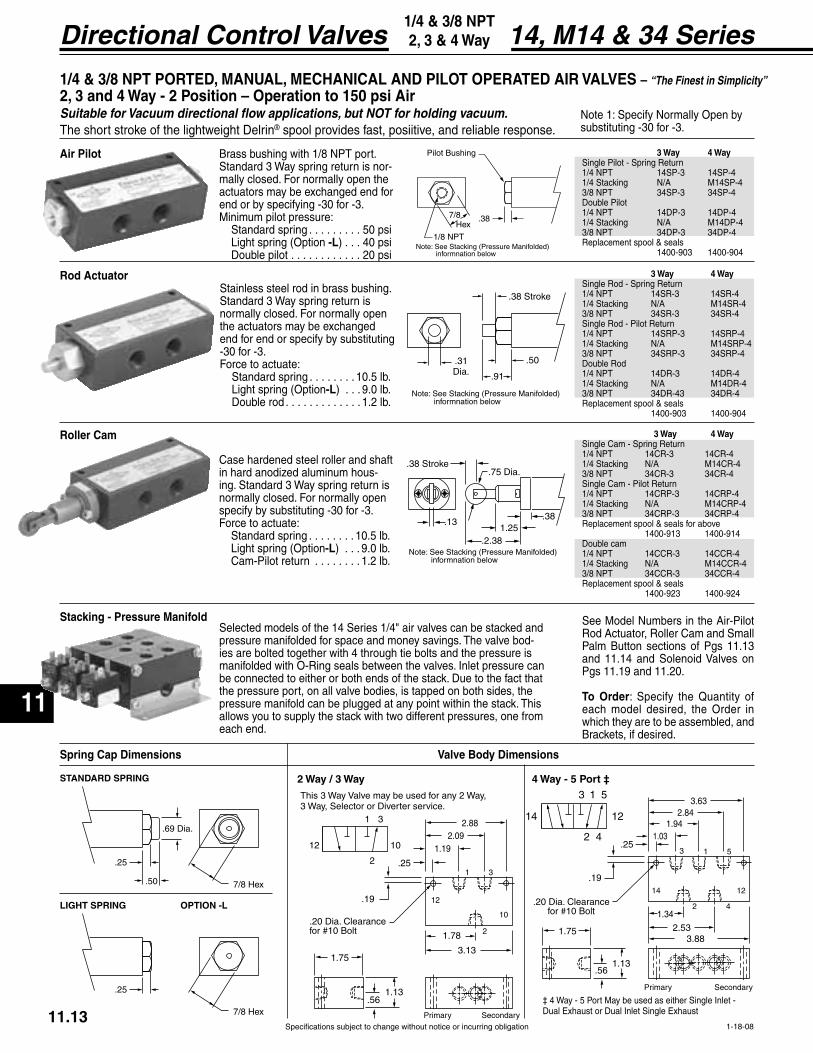
Specifications subject to change without notice or incurring obligation
Directional Control Valves
11
1-18-08
14, M14 & 34 Series1/4 & 3/8 NPT 2, 3 & 4 Way
1/8 NPT
Pilot Bushing
.387/8 Hex
Note: See Stac informnation below
.31
.91
.50
.38 Stroke
Note: See Stac informnation below
.38
.2.38
.38 Stroke
.131.25
Note: See Stac informnation below
Brass bushing with 1/8 NPT port. Standard 3 Way spring return is nor-mally closed. For normally open the actuators may be exchanged end for end or by specifying -30 for -3.Minimum pilot pressure: Standard spring . . . . . . . . . 50 psi
-L . . . 40 psi . . . . . . . . . . . . 20 psi
3 Way 4 Way
1/4 NPT 14SP-3 14SP-41/4 Stacking N/A M14SP-43/8 NPT 34SP-3 34SP-4
1400-903 1400-904
Stainless steel rod in brass bushing. Standard 3 Way spring return is normally closed. For normally open the actuators may be exchanged end for end or specify by substituting -30 for -3.Force to actuate: Standard spring . . . . . . . . 10.5 lb.
-L . . . 9.0 lb. . . . . . . . . . . . . . 1.2 lb.
3 Way 4 Way
1400-903 1400-904
Case hardened steel roller and shaft in hard anodized aluminum hous-ing. Standard 3 Way spring return is normally closed. For normally open specify by substituting -30 for -3.Force to actuate: Standard spring . . . . . . . . 10.5 lb.
-L . . . 9.0 lb. Cam-Pilot return . . . . . . . . 1.2 lb.
3 Way 4 Way
1400-913 1400-914
1400-923 1400-924
Air Pilot
Roller Cam
Rod Actuator
Stacking - Pressure Manifold
7/8 Hex
.25
.50
STANDARD SPRING
7/8 Hex
.25
LIGHT SPRING OPTION -L
31
2
12 10
2 Way / 3 Way
This 3 Way Valve may be used for any 2 Way,3 Way, erter service.
12
10
21.78
1
1.192.09
2.88
Clearancef
.561.13
1.75
Primary Secondary
3
3.13
.19
.25
3 1 5
2 4
1214
4 Way - 5 Port ‡
14 12
2
2.53
1
1.942.84
3.63
Clearancef
.56
1.34
1.75
Primary Secondary
5
3.88
.19
.251.03
4
1.13
‡ 4 Way - 5 Port May be used as either Single Inlet -
3
Selected models of the 14 Series 1/4" air valves can be stacked and pressure manifolded for space and money savings. The valve bod-ies are bolted together with 4 through tie bolts and the pressure is
the pressure port, on all valve bodies, is tapped on both sides, the pressure manifold can be plugged at any point within the stack. This allows you to supply the stack with two different pressures, one from each end.
See Model Numbers in the Air-Pilot
Palm Button sections of Pgs 11.13 and 11.14 and Solenoid Valves on Pgs 11.19 and 11.20.
To Ordereach model desired, the Order in which they are to be assembled, and Brackets, if desired.
Valve Body Dimensions
1/4 & 3/8 NPT PORTED, MANUAL, MECHANICAL AND PILOT OPERATED AIR VALVES – “The Finest in Simplicity”
Suitable for Vacuum directional flow applications, but NOT for holding vacuum.® spool provides fast, posiitive, and reliable response.
Note 1: Specify Normally Open by substituting -30 for -3.
11.13

Specifications subject to change without notice or incurring obligation
11
Directional Control Valves
Pilot Bushing
No. 1400-18 1/8 NPT Port
2-7-08
14, M14 & 34 Series1/4 & 3/8 NPT 2, 3 & 4 Way
.75
1.09.50
.38 Stroke
1.251.03
.50
.38 Stroke
1.38 .81
1.81
.50
3/4-16.38 Stroke
x x .13 thick brass nuts included
1.00
25°
1.75
Leverposition when spring returned.
3.50
1.00 Dia.
®–G Grease
56.2 SCFM Free Flow to Atmosphere at 80 psi Supply
Solenoid controlled models +150°F max. See pages 11.17, 11.19 & 11.21.
Aluminum bar body
single inlet - dual exhaust or dual inlet - single exhaust.
FEATURES OPTIONS-L
Viton seals – Specify Option -V
Consult factory.
Un-anodized aluminum button with stainless steel rod in brass bush-ing. Standard 3 Way spring return is normally closed. For normally open the actuators may be exchanged end for end or specify by substituting -30 for -3.Force to actuate: Standard spring ............... 10.5 lb.
-L ..... 9.0 lb. .................... 1.2 lb.
3 Way 4 Way
1/4 NPT 14PS-3 14PS-41/4 Stacking N/A M14PS-4 3/8 NPT 34PS-3 34PS-4
1/4 NPT 14PSP-3 14PSP-41/4 Stacking N/A M14PSP-4 3/8 NPT 34PSP-3 34PSP-4
1/4 NPT 14PPS-3 14PPS-41/4 Stacking N/A M14PPS-43/8 NPT 34PPS-3 34PPS-4
1400-903 1400-904
stainless steel rod in brass bush-ing. Standard 3 Way spring return is normally closed. For normally open the actuators may be exchanged end for end or specify by substituting -30 for -3.Force to actuate: Standard spring ............... 10.5 lb.
-L ..... 9.0 lb. .................... 1.2 lb.
Phenolic button with plated steel black button
standard, red button Option -R. Standard 3 Way assemblies are normally closed with knob in the
specify by substituting -30 for -3.Force to actuate: Standard spring .............. 10.5 lb.
-L ..... 9.0 lb. ........................... 3.0 lb.
Hardened & plated steel shaft with unique connection to spool results in positive shifting. Standard 3 Way spring return is normally closed. For normally open specify by substituting -30 for -3. Force to actuate: Standard spring . . . 10.0 lb.
. . . . . . 6.0 lb.-L
. . . . . . . . . 3.0 lb.
3 Way 4 Way
1400-903 1400-904
3 Way 4 Way
1400-933† 1400-934†
† Includes factory assembled spool attachments
Palm ButtonAssembly
No. 1400-1No. 1400-2 Small Button
Panel Mount Button Assembly
Black button standard -R
Rod ActuatorAssembly
No. 1400-3
Assembly
No. 1400-4 -LNo. 1400-5 Standard Spring onlyNo. 1400-46 -LNo. 1400-56 Standard Spring & Housing Assembly .
MOST THREADED-IN OPERATORS ARE INTERCHANGEABLE BETWEEN ENDS
Fabco-Air has the expertise and willingness to design. modify and adapt these valves to your necessary and specific job requirements. Please advise us of your needs.
No. 1400-7-3 1400-7-30 Above NOT interchangeable End for End 1400-7-4
1400-8
Small Palm Button
Large Palm Button
Hand Lever
Panel Mount Button 3 Way 4 Way
1/4 NPT 14PMS-3 14PMS-43/8 NPT 34PMS-3 34PMS-4
1/4 NPT 14PMP-3 14PMP-43/8 NPT 34PMP-3 34PMP-4
1400-903 1400-904
1400-943† 1400-944†† Includes factory assembled spool attach-ments.
Note 1: Specify Normally Open by substituting -30 for -3.
11.14
OPERATING TEMPERATURE FOOTNOTE SEE PAGE 11.1
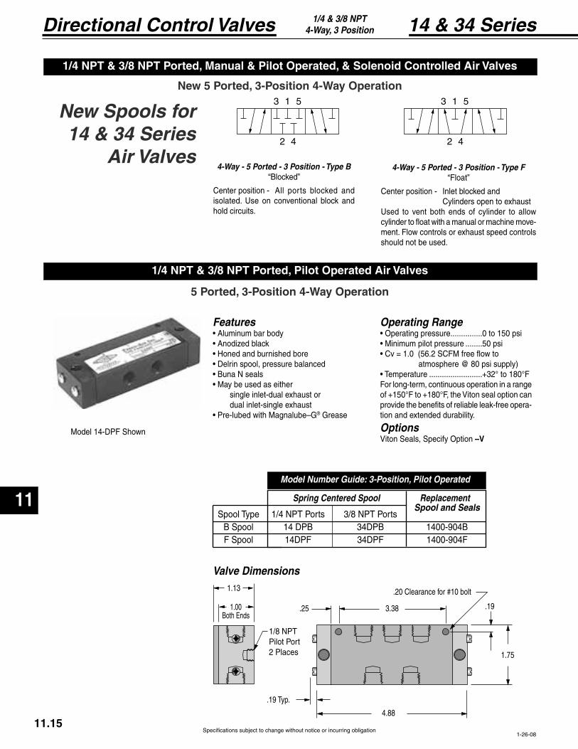
Specifications subject to change without notice or incurring obligation
Directional Control Valves
11
14 & 34 Series1/4 & 3/8 NPT4-Way, 3 Position
3 1 5
2 4
1
3 1 5
2 4
1
4-Way - 5 Ported - 3 Position - Type F
Center position - Inlet blocked and Cylinders open to exhaustUsed to vent both ends of cylinder to allow
-ment. Flow controls or exhaust speed controls should not be used.
4-Way - 5 Ported - 3 Position - Type B
Center position - All ports blocked and isolated. Use on conventional block and hold circuits.
New Spools for 14 & 34 Series
Air Valves
Features
single inlet-dual exhaust or dual inlet-single exhaust
® Grease
Operating Range...............0 to 150 psi
........50 psi
.........................+32° to 180°FFor long-term, continuous operation in a range of +150°F to +180°F, the Viton seal option can provide the benefits of reliable leak-free opera-tion and extended durability.
OptionsViton Seals, Specify Option –V
Valve Dimensions
1-26-08
Model Number Guide: 3-Position, Pilot Operated
Spring Centered Spool Replacement
Spool Type 1/4 NPT Ports 3/8 NPT Ports Spool and Seals
11.15
.20 Clearance f
1/8 NPTPilot Port2 Places
1.00Both Ends
1.13
.19 Typ.
4.88
.25 3.38
1.75
.19
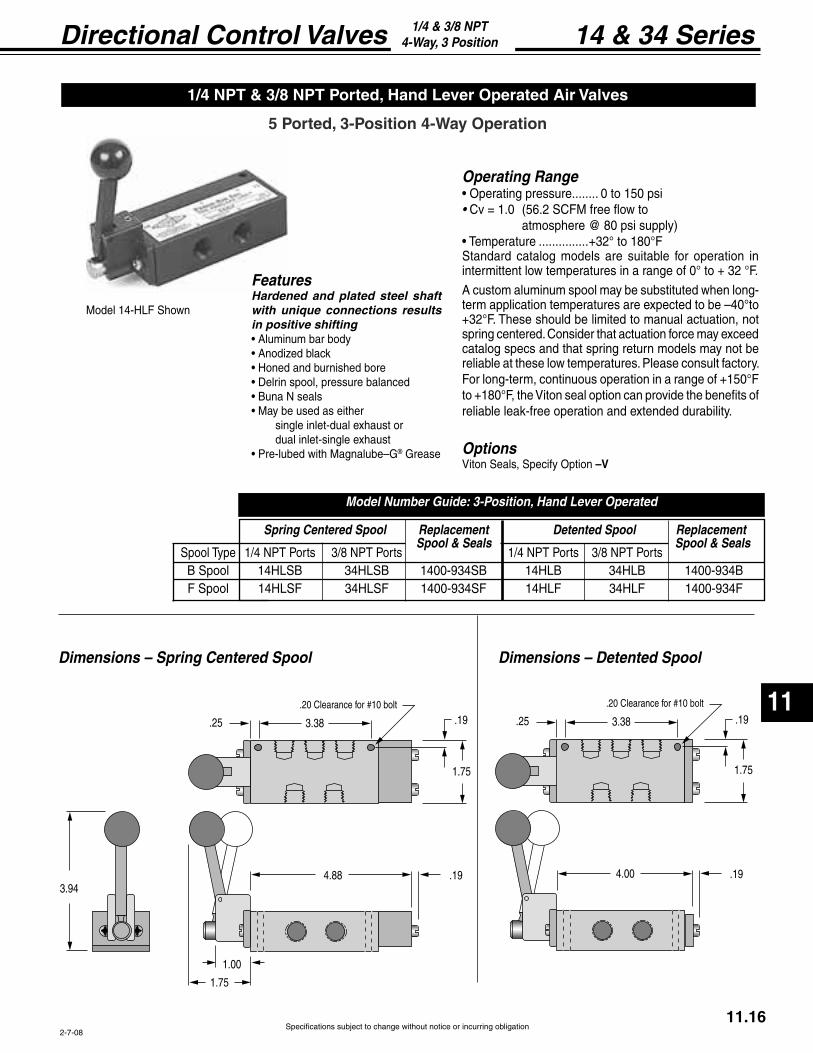
Specifications subject to change without notice or incurring obligation
11
Directional Control Valves 14 & 34 Series1/4 & 3/8 NPT4-Way, 3 Position
Operating Range........ 0 to 150 psi
Cv = 1.0
...............+32° to 180°FStandard catalog models are suitable for operation in intermittent low temperatures in a range of 0° to + 32 °F.
A custom aluminum spool may be substituted when long-term application temperatures are expected to be –40°to +32°F. These should be limited to manual actuation, not spring centered. Consider that actuation force may exceed catalog specs and that spring return models may not be reliable at these low temperatures. Please consult factory. For long-term, continuous operation in a range of +150°F to +180°F, the Viton seal option can provide the benefits of reliable leak-free operation and extended durability.
OptionsViton Seals, Specify Option –V
Dimensions – Spring Centered Spool Dimensions – Detented Spool
2-7-08
Spring Centered Spool Replacement Detented Spool Replacement
Spool Type 1/4 NPT Ports 3/8 NPT Ports 1/4 NPT Ports 3/8 NPT Ports
Model Number Guide: 3-Position, Hand Lever Operated
Spool & Seals Spool & Seals
11.16
.20 Clearance f
3.38.25
1.75
.19
4.88
1.75
1.00
3.94.19
.20 Clearance f
3.38.25
1.75
.19
4.00 .19
FeaturesHardened and plated steel shaft with unique connections results in positive shifting
single inlet-dual exhaust or dual inlet-single exhaust
® Grease
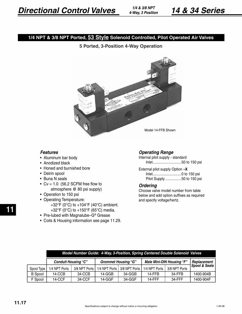
Specifications subject to change without notice or incurring obligation
Directional Control Valves
11
14 & 34 Series1/4 & 3/8 NPT4-Way, 3 Position
Features
® Grease
Operating RangeInternal pilot supply - standard Inlet .............................50 to 150 psi
External pilot supply Option –X Inlet .............................0 to 150 psi Pilot Supply ................50 to 150 psi
OrderingChoose valve model number from table below and add option suffixes as requiredand specify voltage/hertz.
Model 14-FFB Shown
1/4 NPT & 3/8 NPT Ported, 53 Style
1-26-08
Conduit Housing “C” Grommet Housing “G” Male Mini-DIN Housing “F” Replacement
Spool Type 1/4 NPT Ports 3/8 NPT Ports 1/4 NPT Ports 3/8 NPT Ports 1/4 NPT Ports 3/8 NPT Ports B Spool 14-CCB 34-CCB 14-GGB 34-GGB 14-FFB 34-FFB 1400-904B F Spool 14-CCF 34-CCF 14-GGF 34-GGF 14-FFF 34-FFF 1400-904F
Model Number Guide: 4-Way, 3-Position, Spring Centered Double Solenoid Valves
Spool & Seals
11.17

Specifications subject to change without notice or incurring obligation
11
Directional Control Valves 14 & 34 Series1/4 & 3/8 NPT4-Way, 3 Position
.20 Clearance f
.25 3.38
1.75
.19
3.886.38
1.13
2.65
1.50
.63
1.03
1.251/2 NPT
10-32 Exhaust Port
Housing can rotate 360°
1.03
10-32 Exhaust Port
1.50
.75
.63
Housing can rotate 360°
Conduit Housing "C"
Grommet Housing "G"
Male Mini-DIN Housing "F"
53 Style Solenoid Operators
The solenoid operator is a 3-way NC valve which, upon receiving an electrical signal, directs pressure to shift the main valve spool. As standard, the operator is internally supplied with air pressure from the main valve inlet.
In the following listed applications, as well as many others, a proper air supply may not be available from the main valve inlet. For these applications, an external pilot supply port is
this port then supplies the solenoid with air pressure for piloting the main valve spool.
Valve Dimensions
8-26-04
1.75 1.25
.75.14 Max.
1.13.44
1/8 NPT
11.18
1.58.44
.88
10-32Exhaust
Port
.43
.22
(11 mm)spacing
.47.37
.571.50
Line Terminals.25 x .03
Ground Terminal.25 x .03Housing can rotate 360°
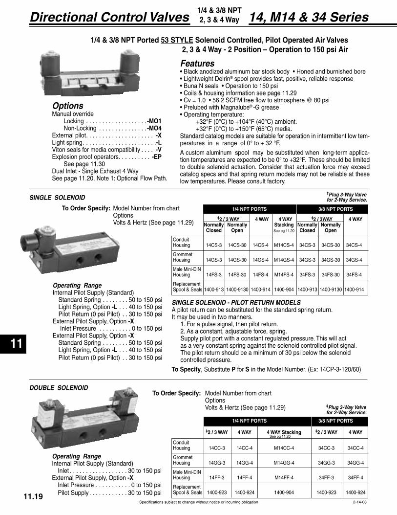
Specifications subject to change without notice or incurring obligation
Directional Control Valves
11
11.192-14-08
14, M14 & 34 Series1/4 & 3/8 NPT 2, 3 & 4 Way
1/4 & 3/8 NPT Ported 53 STYLE
OptionsManual override
. . . . . . . . . . . . . . . . . . . -MO1 . . . . . . . . . . . . . . . -MO4
External pilot. . . . . . . . . . . . . . . . . . . . . -X. . . . . . . . . . . . . . . . . . . . . . .-L
Viton seals for media compatibility . . . . -VExplosion proof operators. . . . . . . . . . -EP See page 11.30
See page 11.20, Note 1: Optional Flow Path.
Operating Range
Standard Spring . . . . . . . . 50 to 150 psi-L . . . 40 to 150 psi
. . 30 to 150 psiExternal Pilot Supply, Option -X Inlet Pressure . . . . . . . . . . 0 to 150 psiExternal Pilot Supply, Option -X Standard Spring . . . . . . . . 50 to 150 psi
-L . . . 40 to 150 psi . . 30 to 150 psi
Operating Range
Inlet . . . . . . . . . . . . . . . . . . 30 to 150 psiExternal Pilot Supply, Option -X Inlet Pressure . . . . . . . . . . . 0 to 150 psi Pilot Supply . . . . . . . . . . . . 30 to 150 psi
SINGLE SOLENOID - PILOT RETURN MODELSA pilot return can be substituted for the standard spring return.It may be used in two manners. 1. For a pulse signal, then pilot return. 2. As a constant, adjustable force, spring. Supply pilot port with a constant regulated pressure. This will act as a very constant spring against the solenoid controlled pilot signal. The pilot return should be a minimum of 30 psi below the solenoid controlled pressure.
, Substitute P for S
SINGLE SOLENOID
DOUBLE SOLENOID
‡2 / 3 WAY 4 WAY 4 WAY Stacking ‡2 / 3 WAY 4 WAY
Conduit Housing 14CC-3 14CC-4 M14CC-4 34CC-3 34CC-4
Grommet Housing 14GG-3 14GG-4 M14GG-4 34GG-3 34GG-4
Housing 14FF-3 14FF-4 M14FF-4 34FF-3 34FF-4
Spool & Seals 1400-923 1400-924 1400-904 1400-923 1400-924
1/4 NPT PORTS 3/8 NPT PORTS
See pg 11.20
‡2 / 3 WAY 4 WAY 4 WAY ‡2 / 3WAY 4 WAY Normally Normally Stacking Normally Normally
See pg 11.20
Conduit Housing 14CS-3 14CS-30 14CS-4 M14CS-4 34CS-3 34CS-30 34CS-4
Grommet Housing 14GS-3 14GS-30 14GS-4 M14GS-4 34GS-3 34GS-30 34GS-4
Housing 14FS-3 14FS-30 14FS-4 M14FS-4 34FS-3 34FS-30 34FS-4
Spool & Seals 1400-913 1400-9130 1400-914 1400-904 1400-913 1400-9130 1400-914
1/4 NPT PORTS 3/8 NPT PORTS
‡Plug 3-Way Valve for 2-Way Service.
‡Plug 3-Way Valve for 2-Way Service.
Features® spool provides fast, positive, reliable response
® -G grease
Standard catalog models are suitable for operation in intermittent low tem-peratures in a range of 0° to + 32 °F.
A custom aluminum spool may be substituted when long-term applica-tion temperatures are expected to be 0° to +32°F. These should be limited to double solenoid actuation. Consider that actuation force may exceed catalog specs and that spring return models may not be reliable at these low temperatures. Please consult factory.
Model Number from chart Options
Model Number from chart Options
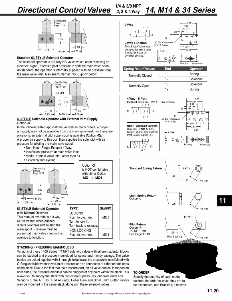
Specifications subject to change without notice or incurring obligation
11
Directional Control Valves
11-8-04
14, M14 & 34 Series1/4 & 3/8 NPT 2, 3 & 4 Way
1.75 1.00.50
.14 Max.
1.13.44
1/8 NPT
.88
See Housing
Page 11.29
1.751.00
.50
1.13
1.34
See Housing
Page 11.29
31
2
12 10
3 Way
This 3 Way Valve may be used for any 2 Way,3 Way, Selector or
erter service.
1210
21.78
1
1.192.09
2.88
Clearancef w
.561.13
1.75
Primary Secondary
3
3.13
.19
.25
2 Way Function
3 1 5
2 4
1214
4 Way - 5 Port Standard: Single Inlet - Port
14 12
2
2.53
1
1.942.84
3.63
Clearancef
.56
1.34
1.75
Primary Secondary
3
3.88
.19
.251.03
4
1.13
5
3 1
214 12
5
4
ow Path: Port
Single Exhaust. Use External -X
Standard 53 STYLEThe solenoid operator is a 3-way NC valve which, upon receiving an electrical signal, directs a pilot pressure to shift the main valve spool. As standard, the operator is internally supplied with air pressure from
53 STYLEOption -XIn the following listed applications, as well as many others, a proper air supply may not be available from the main valve inlet. For these ap-
-XA proper air supply to this port then supplies the solenoid with air pressure for piloting the main valve spool.
53 STYLEwith Manual OverrideThis manual override is a 3-way NC valve that when pushed, directs pilot pressure to shift the main spool. Pressure must be present at main valve inlet for this override to function.
TYPE SUFFIX
Turn back to release.
Push to override. -MO4
STACKING - PRESSURE MANIFOLDEDVersions of these 1400 Series 1/4 NPT solenoid valves with different adaptor blocks can be stacked and pressure manifolded for space and money savings. The valve bodies are bolted together with 4 through tie bolts and the pressure is manifolded with
both sides, the pressure manifold can be plugged at any point within the stack. This allows you to supply the stack with two different pressures, one from each end.
may be mounted in the same stack along with these solenoid valves.
7/8 Hex
.25
.50
Standar
7/8 Hex
.25
Option -L
.25
Pilot ReturnOption -P1/8 NPT PortSee Page 11.13
Pilot Bushing
1/8 NPT
7/8 Hex
10 Spring
12 Solenoid
10 Solenoid
12 Spring
Normally Closed
Normally Open
TO ORDERSpecify the quantity of each model desired, the order in which they are to be assembled, and Brackets, if desired.
11.20
Option -Xis NOT combinable with either Option -MO1 or -MO4
1.751.00
.50
.14 Max.
1.13
See Housing
Page 11.29

Specifications subject to change without notice or incurring obligation
Directional Control Valves
11
11.21
14 & 34 Series1/4 & 3/8 NPT2, 3 & 4-Way
2-14-08
Operating Ranges, psi
0.9 Watts 3.5 Watts
. . . . . . . . . . . . . . . . . . 30 to 130 .........30 to 145
. . . . . . . . . . . . . . . . . . . . . . 50 to 130 .........50 to 145
-L . . . . . . . . . . . . . . . 40 to 130 .........40 to 145
External pilot supply, Option -X inlet pressure . . . . 0 to 150 ...........0 to 150
External pilot supply, Option -X pilot supply
. . . . . . . . . . . . . . . . . . 30 to 130 .........30 to 145
. . . . . . . . . . . . . . . . . . . . . . 50 to 130 .........50 to 145
-L . . . . . . . . . . . . . . . 40 to 130 .........40 to 145
1/4 & 3/8 NPT Ported 58 STYLE 2, 3 & 4 Way - 2 Position
OptionsExternal Pilot . . . . . . . . . . . . . . . . . . . .-X† External Pilot and Viton Seals . . . . -XV
. . . . . . . . . . . . . . . . . . . . .-L
† Viton Seals are available in the main valve only, for media compatibility, and therefore only in conjunction with External
Pilot: + .
Features
® spool provides fast, positive, reliable response
® -G grease
+
Standard catalog models are suitable for operation in intermittent low tempera-tures in a range of 0° to + 32 °F.
A custom aluminum spool may be substituted when long-term application temperatures are expected to be 0° to +32°F. These should be limited to double solenoid actuation. Consider that actuation force may exceed catalog specs and that spring return models may not be reliable at these low temperatures. Please consult factory.
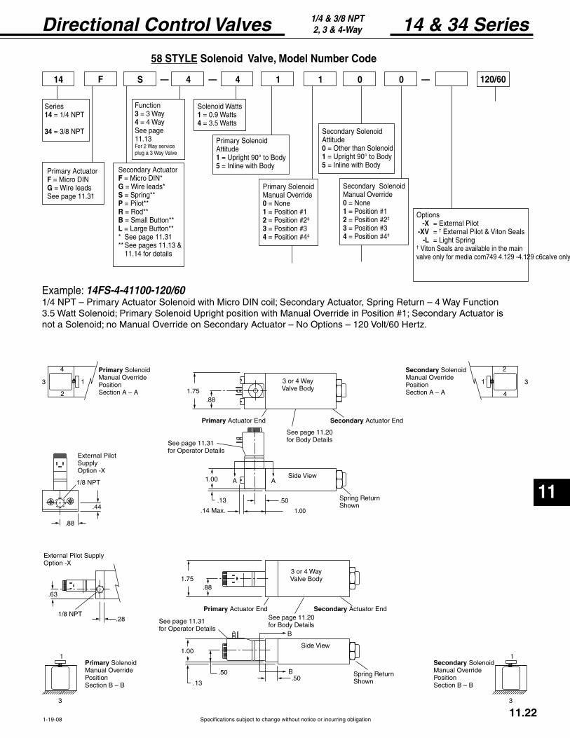
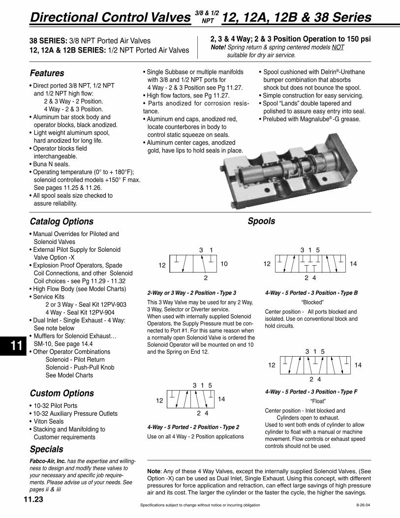
Specifications subject to change without notice or incurring obligation
Directional Control Valves
11
11.23
SpecialsFabco-Air, Inc. has the expertise and willing-ness to design and modify these valves to your necessary and specific job require-ments. Please advise us of your needs. See pages ii & iii
8-26-04
12, 12A, 12B & 38 Series3/8 & 1/2 NPT
3 1 5
2 4
12 14
3 1 5
2 4
12 14
4-Way - 5 Ported - 3 Position - Type F
Center position - Inlet blocked and Cylinders open to exhaust.Used to vent both ends of cylinder to allow
movement. Flow controls or exhaust speed controls should not be used.
4-Way - 5 Ported - 3 Position - Type B
Center position - All ports blocked and isolated. Use on conventional block and hold circuits.
3 1 5
2 4
12 14
3 1
2
12 10
2-Way or 3 Way - 2 Position - Type 3
This 3 Way Valve may be used for any 2 Way,
When used with internally supplied Solenoid Operators, the Supply Pressure must be con-
a normally open Solenoid Valve is ordered the Solenoid Operator will be mounted on end 10 and the Spring on End 12.
4-Way - 5 Ported - 2 Position - Type 2
Use on all 4 Way - 2 Position applications
Note
pressures for force application and retraction, can effect large savings of high pressure air and its cost. The larger the cylinder or the faster the cycle, the higher the savings.
Catalog Options Manual Overrides for Piloted and
Solenoid Valves
Valve Option -X
Coil Connections, and other Solenoid Coil choices - see Pg 11.29 - 11.32
See note below
SM-10, See page 14.4
See Model Charts
Custom Options
Customer requirements
Spools
Features
2 & 3 Way - 2 Position. 4 Way - 2 & 3 Position.
operator blocks, black anodized.
hard anodized for long life.
interchangeable.
solenoid controlled models +150° F max. See pages 11.25 & 11.26.
assure reliability.
with 3/8 and 1/2 NPT ports for 4 Way - 2 & 3 Position see Pg 11.27.
-tance.
locate counterbores in body to control static squeeze on seals.
gold, have lips to hold seals in place.
®-Urethane bumper combination that absorbs shock but does not bounce the spool.
polished to assure easy entry into seal.® -G grease.
38 SERIES 3/8 NPT Ported Air Valves 1/2 NPT Ported Air Valves Note! Spring return & spring centered models NOT
suitable for dry air service.

Specifications subject to change without notice or incurring obligation
11
Directional Control Valves
11.247-28-04
12, 12A, 12B & 38 Series3/8 & 1/2 NPT
PILOT OPERATED
Specify Model Number from chart. Specify Options.
Push - Pull 2 Way - 3 Way 383-PO 123-PO 123B-PO NA
Push 2 Way - 3 Way 383-PS 123-PS 123B-PS NA
Push 2 Way - 3 Way 383-PA 123-PA 123B-PA NA
Push - Push 2 Way - 3 Way 383-PP 123-PP 123B-PP NA
Push - Pull Spring Centered 4 Way 38-PB 12-PB NA 12A-PBType B Spool
Push - Push Spring Centered 4 Way 38-PPB 12-PPB NA 12A-PPB
Type B Spool
Push - Pull Spring Centered 4 Way 38-PF 12-PF NA 12A-PFType F Spool
Push - Push Spring Centered 4 Way 38-PPF 12-PPF NA 12A-PPF
Type F Spool
2 Position
-MO1
OUT -MO3 -MO4
Optional Manual Overrides Model Suffix
1/2 NPT 3/8 NPT 1/2 NPT High Flow
SUBBASEOR
MANIFOLDMOUNTED
Direct Ported
3 Position
Type B Spool
Type F Spool
Type B Spool
Type F Spool
2 Position
1/2 NPT 3/8 NPT 1/2 NPT High Flow
SUBBASEOR
MANIFOLDMOUNTED
Direct Ported
3 Position
HAND LEVER OPERATED
Specify Model Number from chart. Specify Options.
PUSH-PULL KNOB OPERATED
Specify Model Number from chart. Specify Options.
Inlet Presure . . . . . . . . . . . . . . . . . .0 - 150 psi Pilot Pressure:Models without Spring . . . . . . . . . . . . . . . . . . .10 - 150 psi2 Position Standard Service Spring . . . . . . . . .45 - 150 psi
-L . . .30 - 150 psi3 Position, Spring Centered . . . . . . . . . . . . . . .30 - 150 psi
Single Pilot 2 Way - 3 Way 383-SP 123-SP 123B-SP NA
Type B Spool
Type F Spool
2 Position
1/2 NPT 3/8 NPT 1/2 NPT High Flow
SUBBASEOR
MANIFOLDMOUNTED
Direct Ported
3 Position
. . . . . . . . . . . . . . . . . . .0 - 150 psi
. . . . . . . . . . . . . . . . . . .0 - 150 psiStandard knob color is black. For red knob add suffix -R to Model Number.
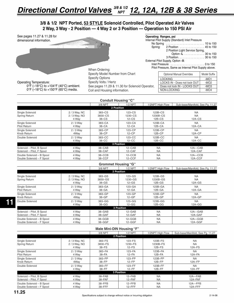
Specifications subject to change without notice or incurring obligation
Directional Control Valves
11
11.252-14-08
12, 12A, 12B & 38 Series3/8 & 1/2 NPT
3/8 & 1/2 NPT Ported, 53 STYLE
No Spring . . . . . . . . . . . . . . . . . . . . . . . . . 10 to 150 Spring: 2 Position . . . . . . . . . . . . . . . . 45 to 150
Option -L . . . . . . . . . . . . . 30 to 150 3 Position. . . . . . . . . . . . . . . . . 30 to 150External Pilot Supply, Option -X: Inlet Pressure . . . . . . . . . . . . . . . . . . . . . . 0 to 150 Pilot Pressure, Same as Internal Pilot Supply above.
See pages 11.27 & 11.28 for dimensional information.
-MO1
OUT -MO3 -MO4
Optional Manual Overrides Model Suffix
When Ordering:Specify Model Number from ChartSpecify OptionsSpecify Volts / HertzSee pages 11.29 & 11.30 for Solenoid Operator,Coil and Housing information.
Grommet Housing “G”
3/8 NPT 1/2 NPT 1/2NPT High Flow Sub-base/Manifold, See Pg. 11.27
Single Solenoid 2 / 3 Way, NC 383–FS 123–FS 123B–FS NA
4 Way 38–FS 12–FS 12B–FS 12A–FS
Single Solenoid 2 / 3 Way 383–FA 123–FA 123B–FA NA
Single Solenoid 2 / 3 Way 383–FP 123–FP 123B–FP NA
4 Way 38–FF 12–FF 12B–FF 12A–FF
Solenoid – Pilot, B Spool 4 Way 38–FAB 12–FAB NA 12A—FABSolenoid – Pilot, F Spool 4 Way 38–FAF 12–FAF NA 12A–FAF
2 Position
3 Position
Male Mini-DIN Housing “F”
3/8 NPT 1/2 NPT 1/2NPT High Flow Sub-base/Manifold, See Pg. 11.27
Single Solenoid 2 / 3 Way, NC 383–GS 123–GS 123B–GS NA
4 Way 38–GS 12–GS 12B–GS 12A–GS
Single Solenoid 2 / 3 Way 383–GA 123–GA 123B–GA NA
Single Solenoid 2 / 3 Way 383–GP 123–GP 123B–GP NA
4 Way 38–GG 12–GG 12B–GG 12A–GG
Solenoid – Pilot, B Spool 4 Way 38–GAB 12–GAB NA 12A—GABSolenoid – Pilot, F Spool 4 Way 38–GAF 12–GAF NA 12A–GAF
2 Position
3 Position
3/8 NPT 1/2 NPT 1/2NPT High Flow Sub-base/Manifold, See Pg. 11.27
Single Solenoid 2 / 3 Way, NC 383–CS 123–CS 123B–CS NA
4 Way 38–CS 12–CS 12B–CS 12A–CS
Single Solenoid 2 / 3 Way 383–CA 123–CA 123B–CA NA
Single Solenoid 2 / 3 Way 383–CP 123–CP 123B–CP NA
4 Way 38–CC 12–CC 12B–CC 12A–CC
Solenoid – Pilot, B Spool 4 Way 38–CAB 12–CAB NA 12A—CABSolenoid – Pilot, F Spool 4 Way 38–CAF 12–CAF NA 12A–CAF
2 Position
3 Position
Conduit Housing “C”
Operating Temperature:
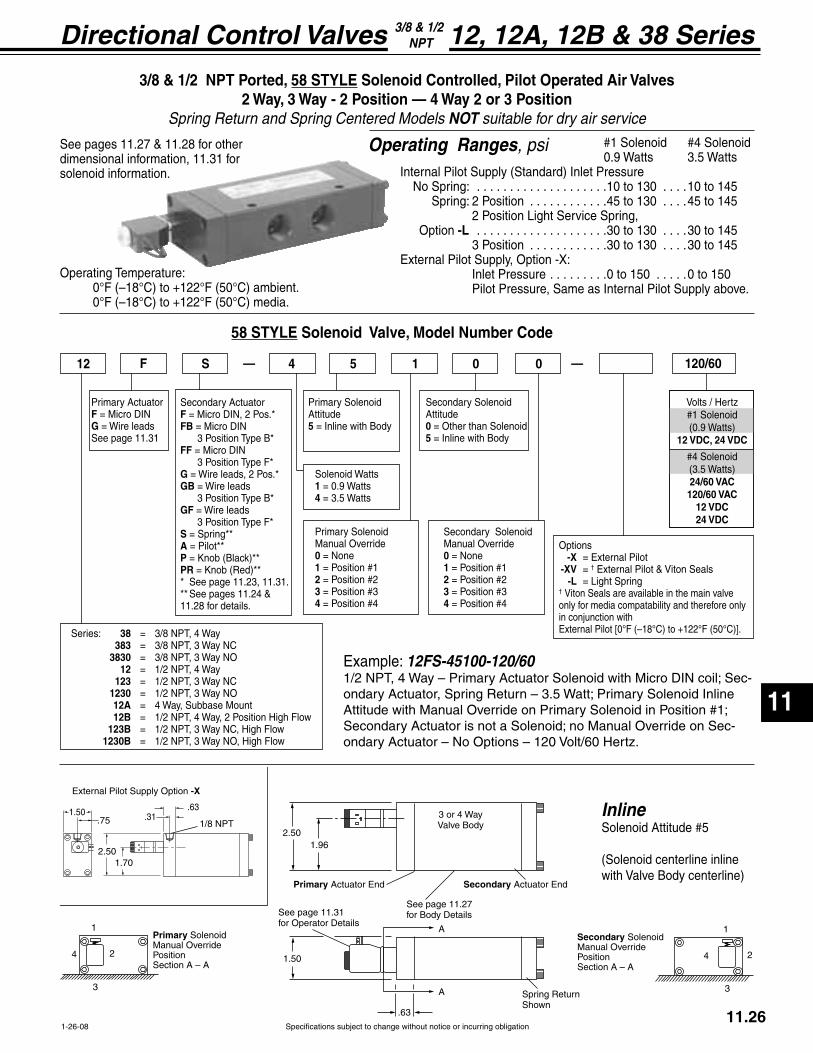
Specifications subject to change without notice or incurring obligation
11
Directional Control Valves
11.261-26-08
12, 12A, 12B & 38 Series3/8 & 1/2 NPT
1
3
Primary SolenoidManual OverridePosition Section A – A
24
1
3
24
Secondary SolenoidManual OverridePosition Section A – A
1/8 NPT1.50
1.70
.75
External Pilot Supply Option -X
2.50
.63.31
Primary Actuator End
2.501.96
Spr nShown
1.50
Secondary Actuator End
A
A
Side View
3 or 4 WayValve Body
See page 11.27fSee page 11.31
f
.63
58 STYLE Solenoid Valve, Model Number Code
Primary ActuatorFG = Wire leadsSee page 11.31
12 F S 4 5 1 0 120/60— —
Primary SolenoidAttitude5 = Inline with Body
Primary SolenoidManual Override0 = None1 234
Secondary SolenoidAttitude0 = Other than Solenoid5 = Inline with Body
Volts / Hertz
12 VDC, 24 VDC
24/60 VAC120/60 VAC
12 VDC24 VDC
Example: 12FS-45100-120/60-
-ondary Actuator – No Options – 120 Volt/60 Hertz.
Secondary SolenoidManual Override0 = None1 234
0
Secondary ActuatorFFB
FF
GGB = Wire leads
GF = Wire leads
SAPPR
11.28 for details.
Options -X = External Pilot -XV = † External Pilot & Viton Seals -L† Viton Seals are available in the main valve only for media compatability and therefore only in conjunction with
Series: 38 = 3/8 NPT, 4 Way 383 = 3/8 NPT, 3 Way NC 3830 = 3/8 NPT, 3 Way NO 12 = 1/2 NPT, 4 Way 123 = 1/2 NPT, 3 Way NC 1230 = 1/2 NPT, 3 Way NO 12A = 4 Way, Subbase Mount 12B = 1/2 NPT, 4 Way, 2 Position High Flow 123B = 1/2 NPT, 3 Way NC, High Flow 1230B = 1/2 NPT, 3 Way NO, High Flow
Solenoid Watts1 = 0.9 Watts4 = 3.5 Watts
Inline
3/8 & 1/2 NPT Ported, 58 STYLE 2 Way, 3 Way - 2 Position — 4 Way 2 or 3 Position
Spring Return and Spring Centered Models NOT suitable for dry air service
0.9 Watts 3.5 Watts
No Spring: . . . . . . . . . . . . . . . . . . . .10 to 130 . . . .10 to 145 Spring: 2 Position . . . . . . . . . . . .45 to 130 . . . .45 to 145
Option -L . . . . . . . . . . . . . . . . . . . .30 to 130 . . . .30 to 145 3 Position . . . . . . . . . . . .30 to 130 . . . .30 to 145External Pilot Supply, Option -X: Inlet Pressure . . . . . . . . .0 to 150 . . . . .0 to 150 Pilot Pressure, Same as Internal Pilot Supply above.
Operating Ranges, psiSee pages 11.27 & 11.28 for other dimensional information, 11.31 for solenoid information.
Operating Temperature:

Specifications subject to change without notice or incurring obligation
Directional Control Valves
11
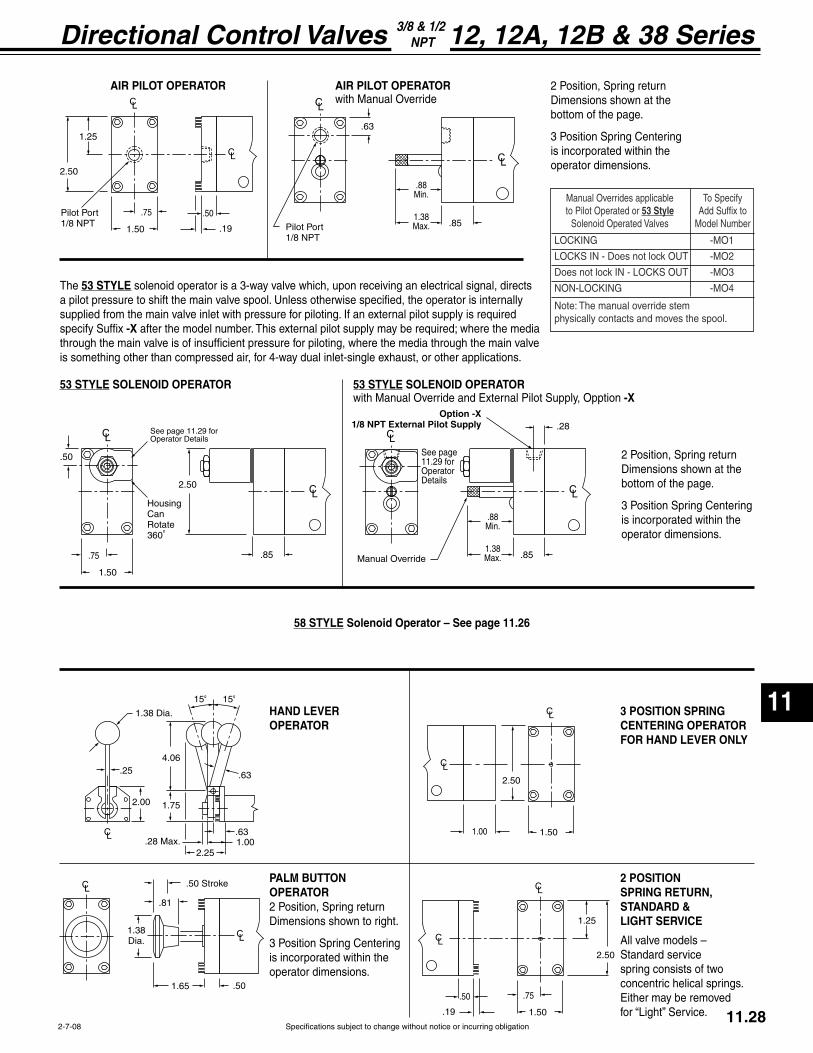
Specifications subject to change without notice or incurring obligation
11
Directional Control Valves
11.282-7-08
12, 12A, 12B & 38 Series3/8 & 1/2 NPT
1.50
.50
.19
2.50
1.25
.75Pilot Port1/8 NPT .85Pilot Port
1/8 NPT
1.38Max.
.88Min.
.63
.85
2.50
.50
1.50
.75
Housing CanRotate360
See page 11.29 forOperator Details
°
.85Manual Override
See page 11.29 forOperator
1.38Max.
.88Min.
.28y
15°
4.06
1.00
15°
1.752.00
.63.25
.63
2.25
1.38 Dia.
.28 Max.
1.38
.50 Stroke
.81
1.65 .50
1.501.00
2.50
1.50
.50
.19
2.50
1.25
.75
AIR PILOT OPERATOR AIR PILOT OPERATOR with Manual Override
2 Position, Spring return
bottom of the page.
3 Position Spring Centeringis incorporated within theoperator dimensions.
53 STYLE SOLENOID OPERATOR with Manual Override and External Pilot Supply, Opption -X
53 STYLE SOLENOID OPERATOR
2 Position, Spring return
bottom of the page.
3 Position Spring Centeringis incorporated within theoperator dimensions.
The 53 STYLE solenoid operator is a 3-way valve which, upon receiving an electrical signal, directs a pilot pressure to shift the main valve spool. Unless otherwise specified, the operator is internally supplied from the main valve inlet with pressure for piloting. If an external pilot supply is required specify Suffix -Xthrough the main valve is of insufficient pressure for piloting, where the media through the main valve is something other than compressed air, for 4-way dual inlet-single exhaust, or other applications.
HAND LEVEROPERATOR
PALM BUTTONOPERATOR2 Position, Spring return
3 Position Spring Centeringis incorporated within the operator dimensions.
2 POSITIONSPRING RETURN,STANDARD &LIGHT SERVICE
All valve models –Standard service spring consists of two concentric helical springs. Either may be removed
3 POSITION SPRING CENTERING OPERATOR FOR HAND LEVER ONLY
58 STYLE
-MO1
OUT -MO3
-MO4
Note: The manual override stemphysically contacts and moves the spool.
Manual Overrides applicableto Pilot Operated or 53 Style
Solenoid Operated Valves
To SpecifyAdd Suffix to
Model Number

Specifications subject to change without notice or incurring obligation
Directional Control Valves
11
11.293-12-08
1.50
.63
1.03
1.251/2 NPT
10-32 Exhaust Port
Housing can rotate 360°
1.03
10-32 Exhaust Port
1.50
.75
.63
Housing can rotate 360°
1.58.44
.88
10-32Exhaust
Port
.43
.22
(11 mm)spacing
.47.37
.571.50
Line Terminals.25 x .03
Ground Terminal.25 x .03Housing can rotate 360°
53 STYLE Stocked Coils and Housings
Conduit Housing “C” and Grommet Housing “G”
Stocked Voltages:
Others available, see Options on page 11.30.
Male Mini-DIN Housing “F”
See page 11.30 for connectors or contact your local distributor for additional choices.Can also be connected with individual .25" quick connect terminals.Stocked Voltages:
Others available, see Options on page 11.30.
.
AC Volts, 60 Hertz DC Volts
Inrush, Amp
Function Inrush, Amp Holding, Amp or Holding, Amp
2 Way NC 14.4 ÷ Volts 9.7 ÷ Volts 10.4 ÷ Volts
2 Way NO
3 Way NC or NO
Examples 15.2 ÷ 120 = 11.8 ÷ 120 = 10.4 ÷ 12 = .13 Amp .10 Amp .87 Amp
15.2 ÷ Volts 11.8 ÷ Volts 10.4 ÷ Volts
AC Volts, 60 Hertz DC Volts
Inrush, AmpFunction Inrush, Amp Holding, Amp or Holding, Amp
2 Way NC 13.2 ÷ Volts 7.8 ÷ Volts
2 Way NO
3 Way NC or NO
Examples 15.2 ÷ 120 = 9.0 ÷ 120 = 7.2 ÷ 12 = .13 Amp .08 Amp .60 Amp
15.2 ÷ Volts 9.0 ÷ Volts7.2 ÷ Volts
Conduit Housing “C”
Grommet Housing “G”
Male Mini-DIN Housing “F”
Spade terminals accept miniature rectangular quick connect socket
-
connect terminals.
Solenoid, Coil and Housing Information 53 Style
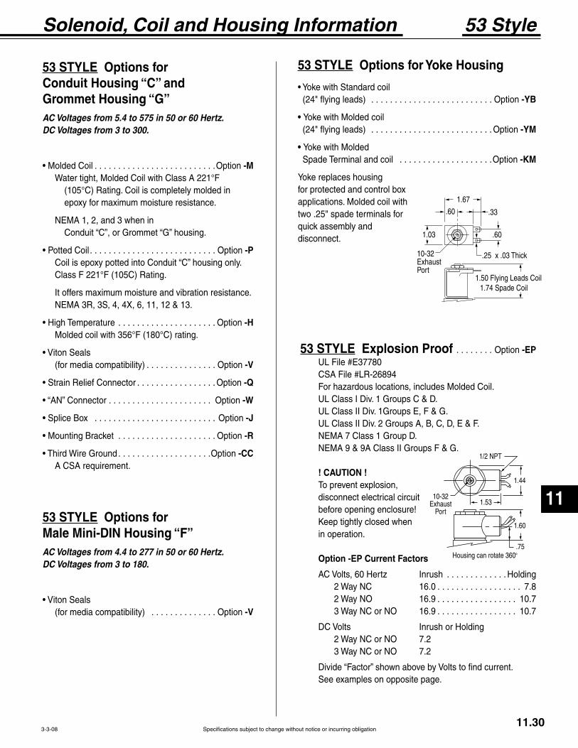
Specifications subject to change without notice or incurring obligation
11
Directional Control Valves
11.303-3-08
53 STYLE Conduit Housing “C” and Grommet Housing “G”AC Voltages from 5.4 to 575 in 50 or 60 Hertz.DC Voltages from 3 to 300.
. . . . . . . . . . . . . . . . . . . . . . . . . .Option -M Water tight, Molded Coil with Class A 221°F
epoxy for maximum moisture resistance.
NEMA 1, 2, and 3 when in
. . . . . . . . . . . . . . . . . . . . . . . . . . . Option -P
It offers maximum moisture and vibration resistance.
. . . . . . . . . . . . . . . . . . . . . Option -H
. . . . . . . . . . . . . . . Option -V
. . . . . . . . . . . . . . . . . Option -Q
. . . . . . . . . . . . . . . . . . . . . . Option -W
. . . . . . . . . . . . . . . . . . . . . . . . . . Option -J
. . . . . . . . . . . . . . . . . . . . . Option -R
. . . . . . . . . . . . . . . . . . . .Option -CC A CSA requirement.
53 STYLE Male Mini-DIN Housing “F”AC Voltages from 4.4 to 277 in 50 or 60 Hertz.DC Voltages from 3 to 180.
. . . . . . . . . . . . . . Option -V
53 STYLE
. . . . . . . . . . . . . . . . . . . . . . . . . . Option -YB
Yoke with Molded coil . . . . . . . . . . . . . . . . . . . . . . . . . . Option -YM
Yoke with Molded Spade Terminal and coil . . . . . . . . . . . . . . . . . . . .Option -KM
Yoke replaces housingfor protected and control boxapplications. Molded coil withtwo .25" spade terminals forquick assembly anddisconnect.
Solenoid, Coil and Housing Information 53 Style
1.53
1.60
1.44
.75Housing can rotate 360°
1/2 NPT
10-32Exhaust
Port
.60
1.67
.33
.60
.25 x .03 Thick
1.74 Spade Coil
10-32Exhaust Port
1.03
53 STYLE . . . . . . . . Option -EP
For hazardous locations, includes Molded Coil.
NEMA 9 & 9A Class II Groups F & G.
! CAUTION ! To prevent explosion,disconnect electrical circuitbefore opening enclosure!
in operation.
AC Volts, 60 Hertz Inrush . . . . . . . . . . . . . Holding 2 Way NC 16.0 . . . . . . . . . . . . . . . . . . 7.8 2 Way NO 16.9 . . . . . . . . . . . . . . . . . 10.7 3 Way NC or NO 16.9 . . . . . . . . . . . . . . . . . 10.7
2 Way NC or NO 7.2 3 Way NC or NO 7.2
See examples on opposite page.

Specifications subject to change without notice or incurring obligation
Directional Control Valves
11
Specifications subject to change without notice or incurring obligation
Directional Control Valves
11
11.313-12-08
1.36
.44
.63
.30
.27
.19
.19
1.89
Ground Terminal.14 x .02
Terminal.11 x .02Exhaust Port
.25
Manual overrideif ordered
1.06
.44
.63
1.89
A
Exhaust Port
.25
Manual overrideif ordered
58 Style 58 Style
Volts Hertz Inrush Holding
24 60 252 220
120 60 43 37
58 Style3 Way – Normally Closed – Exhaust to Atmosphere
Available with or without Push Button Manual Override
Solenoid, Coil and Housing Information 58 Style
#4 Operator3.5 Watts
3 – 9 ms with AC Volts.1.0 mm Inlet Orifice – 1.0 mm Exhaust Orifice145 psi Maximum Operating Pressure
#1 Operator0.9 Watts Volts – . . . . . . . . . . . . . . . . . . . . . . . . . .
. . . .73 mA . . . . 37 mA
0.6 mm Inlet Orifice – 0.8 mm Exhaust Orifice130 psi Maximum Operating Pressure
Male Micro-DIN, Coil “F”Molded – Water Tight
See page 11.32 for connectors or contact your local distributor for additional choices.
Wire Leads, Coil “G”Molded – Water Tight

Specifications subject to change without notice or incurring obligation
11
Directional Control Valves
Specifications subject to change without notice or incurring obligation
11
Directional Control Valves
11.323-12-08
Solenoid Accessories 53 & 58 Style
Solenoid Exhaust Mufflers, #SM-10
Flat Gasket, Nitrile Ribber
Housing can rotate around receptacle, in 90 increments, to locate cable in desired attitude.
M3 Connector Screw
1.02
1.38
.61
Receptacle with 9.4 mm spacingmates withMicro-DIN Coil “F”
.26 Max. Cable Dia.18 Ga. Max. Wire Dia.
°
. . . . . . . . . . . . . . . . . . . 192-07-N Black Housing
. . . . . . . . . . 192-07-T-A.1-Voltage
Connectors 58 Style
Hard Wired Connectors . . . . . . . . . . . . . . . . . . . . . . . . . Please see Section 16
Connectors 53 Style
. . . . . . . . . . . . . . . . 122-09-N Black Housing
. . . . . . . . . 122-09-T-A.1-Voltage
Profile Gasket, Nitrile Ribber
Housing can be rotated around receptacle, in 180° increments, to locate cable in desired attitude.
M3 Connector Screw
1.18
2.00
Receptacle with 11 mm spacingmates withMini-DIN Housing “F”
.24 – .27 Cable Diameter16 Ga. Max. Wire Diameter.
.79
.
J Series hard wired connectors
F Series hard wired connectors
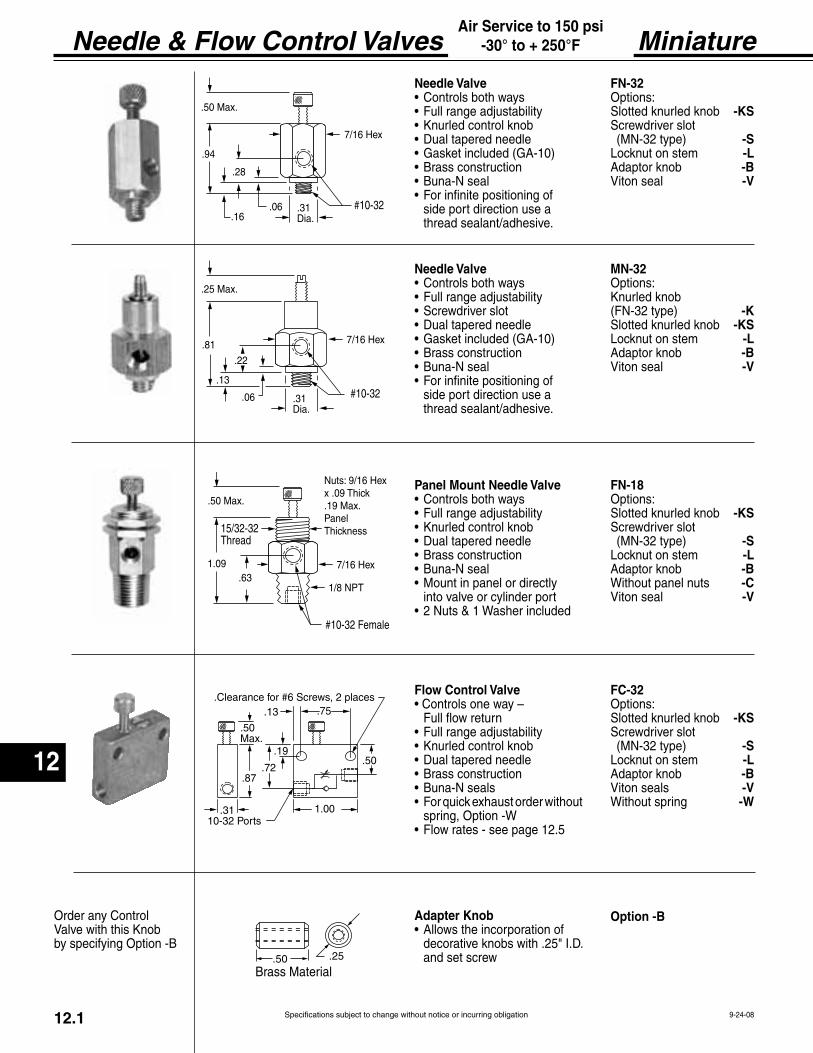
12
Needle & Flow Control Valves
Specifications subject to change without notice or incurring obligation12.1 9-24-08
Air Service to 150 psi-30° to + 250°F Miniature
.50Max.
.13
.87.72
.19
.75
.50
1.00.31 10-32 Ports
.Clearance for #6 Screws, 2 places
.50 Max.
.94
7/16 Hex
.28
.16#10-32.31
Dia..06
.25 Max.
.81 7/16 Hex
.22
.13
.06 #10-32.31Dia.
.50 .25
Needle Valve FN-32Options:
-KS
-S-L-B
Viton seal -V
Needle Valve MN-32Options:
-K-KS
-L-B
Viton seal -V
Panel Mount Needle Valve FN-18Options:
-KS
-S-L-B-C
Viton seal -V
Flow Control Valve FC-32Options:
-KS
-S-L-B
Viton seals -V-W
Adapter Knob Option -B
.50 Max.
7/16 Hex1.09
15/32-32
.63
9/16 Hexx .09 Thic.19 Max.PanelThic

12
Needle & Flow Control Valves
Specifications subject to change without notice or incurring obligation 12.24-20-04
Air Service to 150 psi0° to + 180°F Micro-Fine™
.63 Dia..75
.34 .79
1.69
3/4-16
7/8 Hexx .13 Thic
.75 Dia.
3/4 Hex
10-32 Ports
0 20 40 60 80 1000 .33 .67 1.00 1.33 1.67
KN
OB
TU
RN
S
0
1
2
3
4
5
6
7
8
9
FLOW @80 psi
.63 Dia..75
.34 .79
1.25
3/4-16
7/8 Hexx .13 Thic
.75 Dia.
5/8 Hex
10-32 Ports
NV-55
FC-55
NV-55
FC-55
-
Features
The precision is shown on the chart below. -
Options-V.

12
Needle & Flow Control Valves
Specifications subject to change without notice or incurring obligation
Swivel, Port Mounted
12.3
Port Mounted, Swivel, Brass Body Flow Controls (See next page 12.4)
Port Mounted, Swivel, Molded Body Flow Controls.
SPECIFICATIONS
SPECIFICATIONS
Model No. Description A B max C Flow (Cv)
Knob Adjustable Valves Recessed Screw Adjustable ValvesModel No. Description A B max C Flow (Cv)
PC4-L
C CC C
4-1-08
Easy Disassembly for Maintenance
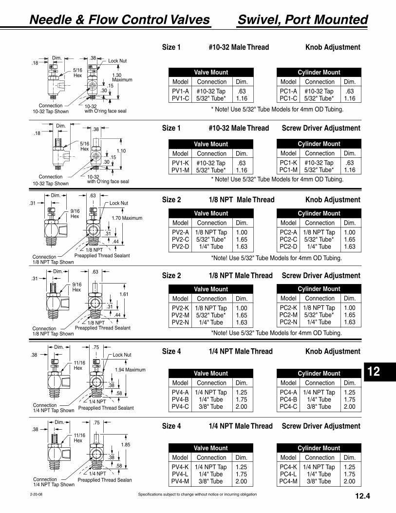
12
Needle & Flow Control Valves
Specifications subject to change without notice or incurring obligation 12.42-20-08
Swivel, Port Mounted
Connection Tap Shown
.31
.63
.31
.44
9/16Hex
Connection Tap Shown
.31.63
.31
.44
9/16Hex
1.61
Connection Tap Shown
.38
.75
.38
.58
11/16Hex
Connection Tap Shown
.38.75
.38
.58
11/16Hex
1.85
Size 1 #10-32 Male Thread Knob Adjustment
Size 1 #10-32 Male Thread Screw Driver Adjustment
Size 2 1/8 NPT Male Thread Knob Adjustment
Size 2 1/8 NPT Male Thread Screw Driver Adjustment
Size 4 1/4 NPT Male Thread Knob Adjustment
Size 4 1/4 NPT Male Thread Screw Driver Adjustment
Valve Mount Cylinder Mount
Valve Mount Cylinder Mount
Valve Mount Cylinder Mount
Valve Mount Cylinder Mount
Valve Mount Cylinder Mount
Valve Mount Cylinder Mount
.18
5/16 Hex
.38
1.10
.30.15
10-32with O'ring face seal
Connection
.185/16 Hex
.38
1.30
.30.15
10-32with O'ring face seal
Connection
10-32 Tap Shown
10-32 Tap Shown
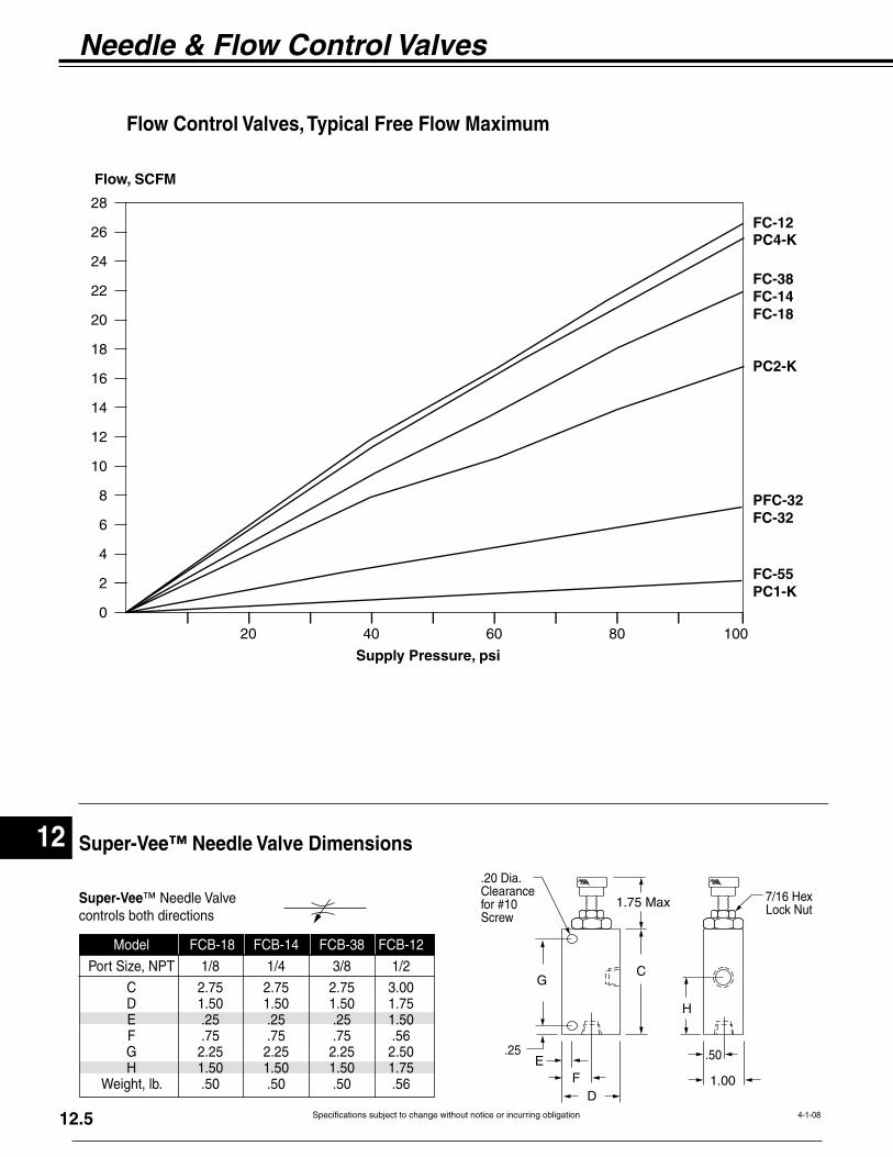
12
Needle & Flow Control Valves
Specifications subject to change without notice or incurring obligation12.5 4-1-08
0
2
4
6
8
10
12
14
16
18
20
22
24
26
28
Flow, SCFM
Supply Pressure, psi
20 40 60 80 100
FC-55PC1-K
PFC-32FC-32
PC2-K
PC4-K
FC-38FC-14FC-18
FC-12
C
H
E
D
.50
1.00
1.75 Max 7/16 HexLoc
.20 Dia.Clearancefor #10Screw
.25
Super-Vee™ Needle Valve Dimensions
Super-Vee
C 2.75 2.75 2.75 3.00 D 1.50 1.50 1.50 1.75 E .25 .25 .25 1.50
H 1.50 1.50 1.50 1.75
Flow Control Valves, Typical Free Flow Maximum
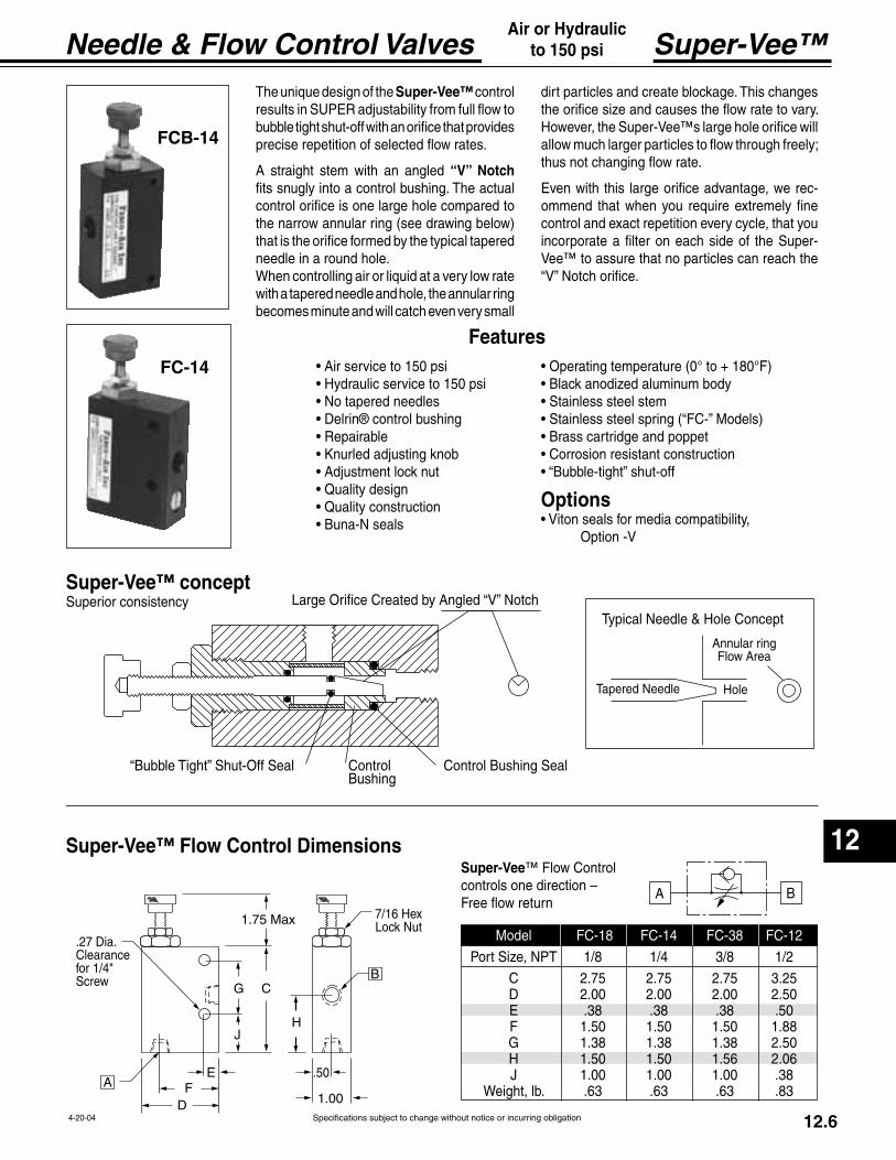
12
Needle & Flow Control Valves
Specifications subject to change without notice or incurring obligation 12.64-20-04
C
E
D
J
.50
1.00
1.75 Max
H
7/16 HexLoc
.27 Dia.ClearancefScrew
ing
HoleT
Control le Shut-Off Seal
Large Or
FCB-14
FC-14
Super-Vee™
Super-Vee
C 2.75 2.75 2.75 3.25 D 2.00 2.00 2.00 2.50 E .38 .38 .38 .50
H 1.50 1.50 1.56 2.06 J 1.00 1.00 1.00 .38
Super-Vee™ control results in
“V” Notch -
Options
Option -V
Super-Vee™ concept
Super-Vee™ Flow Control Dimensions
Features
Air or Hydraulicto 150 psi

13
Special Purpose Valves
Specifications subject to change without notice or incurring obligation 13.210-26-04
Adjustable, Interval Delay
IN EXH
CYLOS-1Modified
Adjustable VolumeChamber
Volume ChamberDump Valve
Volume Chamber VentDo Not Block
Symbol
Interval DelayUpon application of an input signal (pressure) there is an output
signal for an adjustable time, within ranges shown. At the end of this time the output signal is vented. Another output is not pos-sible until the input is vented to atmosphere for 1 second minimum (reset time). Another input signal can then be applied for another output signal.
The time proven Fabco-Air OS-1 Pulse Valve (see page 13.1) is the basis of this unique, all pneumatic, adjustable, Interval Delay. The OS-1 is mounted on and connected to an adjustable volume chamber. When the incoming signal is applied to the IN port of the OS-1, its spool is immediately shifted, and the chamber dump valve is closed. This allows pressure to and through the CYL port, becoming the output signal. Pressure then bleeds across an orifice through the piston head and into the adjustable volume chamber. When pressure is equal on both sides of the piston head there is a force unbalance on the spool. This force unbalance returns the spool to its original position. In this position the incoming signal is blocked and CYL is connected to EXH, in turn venting the output signal. Adjusting the volume of the chamber adjusts the length of the output signal.
Before the valve can produce another signal it must be reset. Resetting is accomplished by removing the input signal from and venting the IN for 1 second minimum. This allows pressure behind the piston to bleed back through the orifice and opens the chamber dump valve. All volume behind the piston then bleeds down to zero psi. This action self cleans the orifice at every cycle. The next incoming signal can then produce another output signal.
NOTE! The incoming signal MUST be of sufficient pressure and volume to shift the spool before bleeding across the orifice and balancing out.
Model OS-5 1 to 6 second output signal
Model OS-6 3 to 8 second output signal
Model OS-7 6 to 13 second output signal
On
OffPressure at IN
On
OffOutput at CYL
Time
Reset
Adjustable Output Signal
.80___3.30
4.691/8 NPTPorts
3.50.591.13 .19
1.59
1.50.19
2.25
1.88
EXHIN
.691.41
Adjusting Knob, 3/4 Dia.
#10-24 x .25 Dp.Mounting Holes, 4 Places
9/16 HexAdjustmentLock Nut
CYL
Chamber Vent Do Not Block
Dimensions
Features
installation.
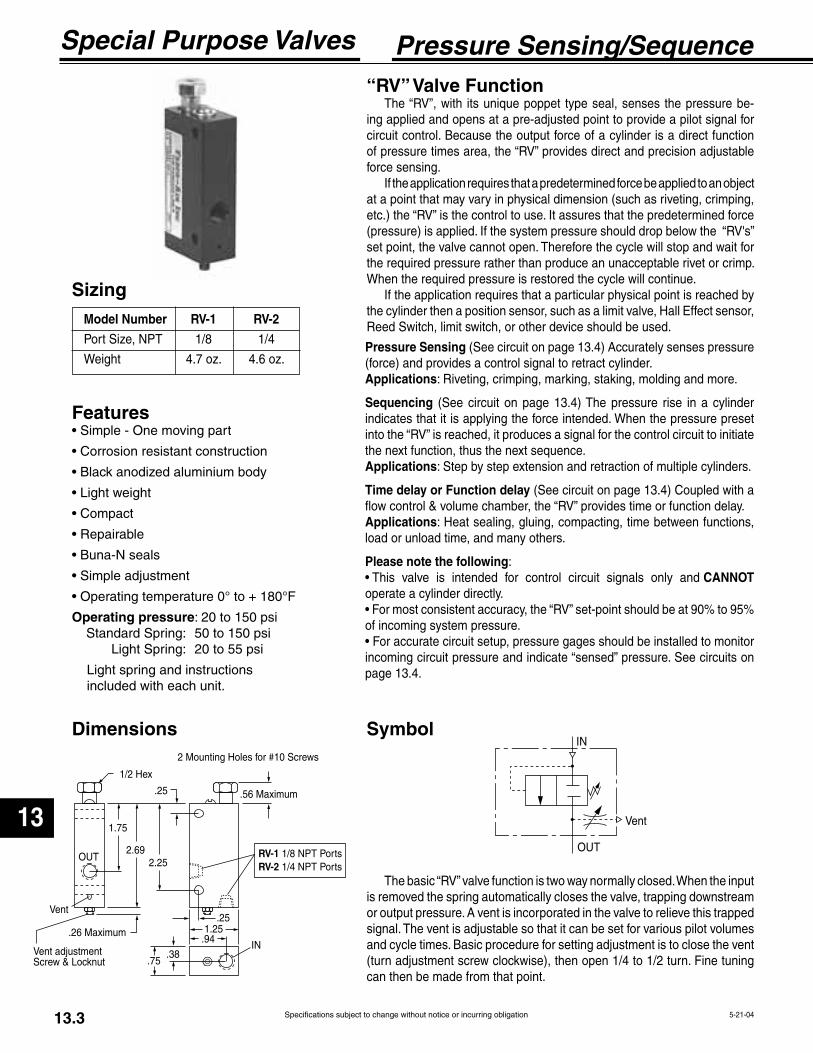
13
Special Purpose Valves
Specifications subject to change without notice or incurring obligation13.3 5-21-04
OUT
Vent
.26 Maximum
1.75
2.692.25
.25
Vent adjustmentScrew & Locknut
IN.941.25
.25
RV-1 1/8 NPT PortsRV-2 1/4 NPT Ports
2 Mounting Holes for #10 Screws
1/2 Hex
.56 Maximum
.75.38
Vent
OUT
IN
Pressure Sensing/Sequence “RV” Valve Function
The “RV”, with its unique poppet type seal, senses the pressure be-ing applied and opens at a pre-adjusted point to provide a pilot signal for circuit control. Because the output force of a cylinder is a direct function of pressure times area, the “RV” provides direct and precision adjustable force sensing.
If the application requires that a predetermined force be applied to an object at a point that may vary in physical dimension (such as riveting, crimping, etc.) the “RV” is the control to use. It assures that the predetermined force (pressure) is applied. If the system pressure should drop below the “RV's” set point, the valve cannot open. Therefore the cycle will stop and wait for the required pressure rather than produce an unacceptable rivet or crimp. When the required pressure is restored the cycle will continue.
If the application requires that a particular physical point is reached by the cylinder then a position sensor, such as a limit valve, Hall Effect sensor, Reed Switch, limit switch, or other device should be used.
Features
Operating pressure
Light spring and instructions included with each unit.
Dimensions Symbol
The basic “RV” valve function is two way normally closed. When the input is removed the spring automatically closes the valve, trapping downstream or output pressure. A vent is incorporated in the valve to relieve this trapped signal. The vent is adjustable so that it can be set for various pilot volumes and cycle times. Basic procedure for setting adjustment is to close the vent (turn adjustment screw clockwise), then open 1/4 to 1/2 turn. Fine tuning can then be made from that point.
Pressure Sensing (See circuit on page 13.4) Accurately senses pressure (force) and provides a control signal to retract cylinder.Applications
Sequencing (See circuit on page 13.4) The pressure rise in a cylinder indicates that it is applying the force intended. When the pressure preset into the “RV” is reached, it produces a signal for the control circuit to initiate the next function, thus the next sequence.Applications
Time delay or Function delay (See circuit on page 13.4) Coupled with a flow control & volume chamber, the “RV” provides time or function delay.Applicationsload or unload time, and many others.
Please note the followingCANNOT
operate a cylinder directly.
of incoming system pressure.
incoming circuit pressure and indicate “sensed” pressure. See circuits on page 13.4.
Sizing Model Number RV-1 RV-2
Port Size, NPT 1/8 1/4
Weight 4.7 oz. 4.6 oz.
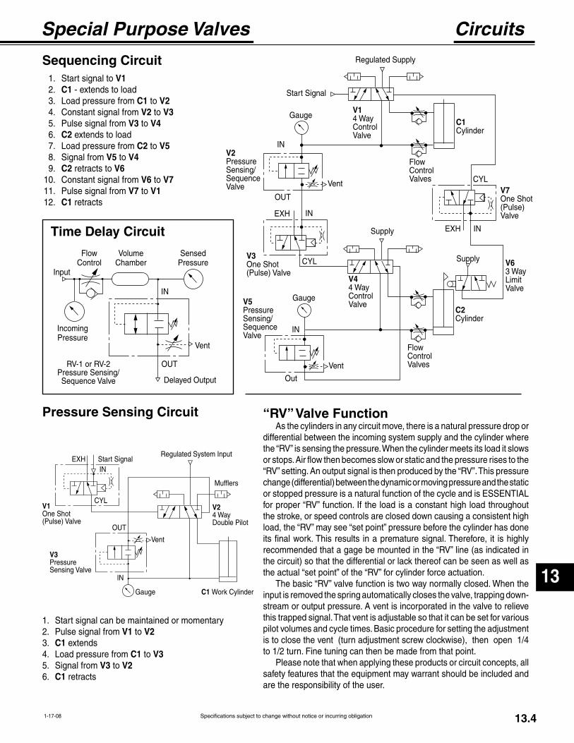
13
Special Purpose Valves
Specifications subject to change without notice or incurring obligation 13.41-17-08
OUT
CYL
INStart Signal
Regulated System Input
Mufflers
V24 WayDouble Pilot
V1One Shot(Pulse) Valve
V3PressureSensing Valve
EXH
Vent
Gauge C1 Work Cylinder
IN
Circuits
RV-1 or RV-2Pressure Sensing/Sequence Valve
FlowControl
IncomingPressure
Vent
OUT
IN
Volume Chamber
SensedPressure
Delayed Output
Input
V7One Shot(Pulse) Valve
V63 WayLimitValve
EXH
CYL
IN
C2Cylinder
FlowControlValves
Supply
C1Cylinder
Regulated Supply
Start Signal
V14 WayControlValve
Vent
IN
OUT
Supply
Vent
Gauge
CYL
INEXH
Out
IN
Gauge
V3One Shot(Pulse) Valve
V2PressureSensing/SequenceValve
V5PressureSensing/SequenceValve
FlowControlValves
V44 WayControlValve
Sequencing Circuit 1. Start signal to V1 2. C1 - extends to load 3. Load pressure from C1 to V2 4. Constant signal from V2 to V3 5. Pulse signal from V3 to V4 6. C2 extends to load 7. Load pressure from C2 to V5 8. Signal from V5 to V4 9. C2 retracts to V6 10. Constant signal from V6 to V7 11. Pulse signal from V7 to V1 12. C1 retracts
Pressure Sensing Circuit
1. Start signal can be maintained or momentary 2. Pulse signal from V1 to V2 3. C1 extends 4. Load pressure from C1 to V3 5. Signal from V3 to V2 6. C1 retracts
Time Delay Circuit
“RV” Valve FunctionAs the cylinders in any circuit move, there is a natural pressure drop or
differential between the incoming system supply and the cylinder where the “RV” is sensing the pressure. When the cylinder meets its load it slows or stops. Air flow then becomes slow or static and the pressure rises to the “RV” setting. An output signal is then produced by the “RV”. This pressure change (differential) between the dynamic or moving pressure and the static or stopped pressure is a natural function of the cycle and is ESSENTIAL for proper “RV” function. If the load is a constant high load throughout the stroke, or speed controls are closed down causing a consistent high load, the “RV” may see “set point” pressure before the cylinder has done its final work. This results in a premature signal. Therefore, it is highly recommended that a gage be mounted in the “RV” line (as indicated in the circuit) so that the differential or lack thereof can be seen as well as the actual “set point” of the “RV” for cylinder force actuation.
The basic “RV” valve function is two way normally closed. When the input is removed the spring automatically closes the valve, trapping down-stream or output pressure. A vent is incorporated in the valve to relieve this trapped signal. That vent is adjustable so that it can be set for various pilot volumes and cycle times. Basic procedure for setting the adjustment is to close the vent (turn adjustment screw clockwise), then open 1/4 to 1/2 turn. Fine tuning can then be made from that point.
Please note that when applying these products or circuit concepts, all safety features that the equipment may warrant should be included and are the responsibility of the user.

13
Special Purpose Valves
Specifications subject to change without notice or incurring obligation13.5 5-21-04
Standard Specifications
Model No. MSV-1Stem ActuatorWeight 0.8 oz.
Model No. MSV-2Lever ActuatorWeight 0.8 oz.
Model No. MSV-2ARoller ActuatorWeight 0.9 oz.
Micro Limit ValvesThis is a microsize, poppet type, 3 way, normally closed, limit valve. It is primarily designed for momentary contact work that requires very light actuating forces.
on the actuating stem. This means that, while the valve is held actuated (and only then), there is a slight bleed to atmosphere around the stem.
MSV-1 Stem Actuator MSV-2 Lever Actuator MSV-2A Roller Actuator
.44
.63
.09
.13
ExhaustNotTapped
#1
1.00
2 Mounting Holes for #6 Sc
.44
.63
.09
.13
ExhaustNotTapped
#10-32 Ports
1.06
1.00.69
.38
.31
2 Mounting Holes for #6 Screws
#10-32 Ports
.44
.63
.09
.13 1.03.69
.38
.311.00
Exhaust Not Tapped
1.38
2 Mounting Holes for #6 Screws
3/8" Dia.#10-32 Ports
.44
.63
.09
.13 1.03.69
.38
.31
1.00
Exhaust Not Tapped
1.25
2 Mounting Holes for #6 Screws
EXHIN
CYL
Symbol
Features
® roller (180° F max.)
.005" to .010" movement of stem normally provides sufficient pilot volume.
Options Specify suffix –V
Specify suffix –R
Note The standard assembly of lever, in relation to ports, is shown in the drawings below. A second lever pivot pin hole allows for the lever to be assembled 180° from standard. Specify Suffix-R, Reverse lever assembly, if required.

13
Special Purpose Valves
Specifications subject to change without notice or incurring obligation 13.65-23-04
Model No. 10 SVWeight 0.4 oz.Flow rating Cv approx. 0.06
Standard Specifications
Features® poppet
Shuttle Valves
Check Valves
Options® O-Ring Seals
Model No. 18 SVWeight 1.4 oz.Flow rating Cv approx. 0.34
Model No. (Cracking Pressure) 18CV. . . . . (without spring 0.3 psi Max.)18CVS . . . . . .(with spring 10 psi Max.)Weight 0.5 oz.Flow rating Cv = 0.1
Features Options® O-Ring Seals
Symbol
Symbol 1.13
1/4 NPT9/16 Hex
.94
1/8 NPT7/16 Hex
Auxiliary#10-32 Port
Model No. (Cracking Pressure) 14CV. . . . . (without spring 0.3 psi Max.)14CVS . . . . . .(with spring 10 psi Max.)Weight 0.8 oz.Flow rating Cv = 0.4
1.38
1/8 NPTPorts
1.13
1/8 NPT
.76
#10-32 Ports.75
#10-32

13
Special Purpose Valves
Specifications subject to change without notice or incurring obligation13.1 10-26-04
One-Shot (Pulse)
.75
1.25
2.31 OS-13.81 OS-3
1.56
.78.44
.28.97
INEX1/8 NPT Ports
2 Mounting Holesfor #10 Screws
.16
Materials:Body, Aluminum, UnanodizedCap, BrassSpool, Aluminum
IN EXH
CYL
Model No. OS-1 & OS-3 1/8 NPT Ports
OperationWhen the incoming signal
is applied to the IN port, the spool is immediately shifted, allowing the pressure to and through the CYL port, becoming the output signal. Pressure then bleeds across an orifice through the piston head. When pres-sure is equal on both sides of the piston head there is a force unbalance on the spool. This force unbalance returns the spool to its original position. In this position the incoming signal is blocked and the CYL is connected to the EXH, in turn venting the output signal.
Before the valve can produce another output signal it must be reset. This is accomplished when the input signal is removed from the IN port and the pressure behind the piston bleeds back through the orifice and drops to zero psi. This also self cleans the orifice every cycle. The next incoming signal can then produce another output signal.
NOTE! The incoming signal MUST be of sufficient pressure and volume to shift the spool before bleeding across the orifice and balancing out.
Sizing Model Weight Number Port Size Oz. OS-1 3/4 1 1/8 NPT 3.1 OS-3 1-1/2 2 1/8 NPT 4.8
ApproximatePulse Time,
Seconds@80 psi
ApproximateResetTime,
Seconds@80 psi
OS-1
Symbol
Features
at factory. (See Model Chart)
field set with ordinary sewing needle.
repaired without removing from installation.
observed for trouble shooting circuit.
45 to 150 psi.
0° to + 180°F.
ApplicationsSignal Conversion - Pulse, to convert a constant or maintained
signal from a limit valve or other source to a pulse or momentary signal for a double piloted valve or other device. This allows the double piloted valve to be shifted back even though the originat-ing limit valve is still held open. See sequencing circuit on page 13.4.
Single Cycle, to convert a signal from a hand or foot control to a pulse signal. This allows only one cycle of the circuit even if the operator holds the starting device on. The operator must release the starting device to reset the one-shot / pulse valve and then reactuate to achieve the next cycle. See pressure sensing circuit on page 13.4.
Open End Blast, to provide a pulse of air through a nozzle or tube for automatic part blow off or chip removal.
Dimensions
This valve provides a momentary (pulse) output at its cylinder port when pressure is applied at its inlet. No additional flow is possible until pressure at the inlet is removed, reset time allowed, and pressure reapplied. Reset time is slightly longer than output pulse time.
Specifications subject to change without notice or incurring obligation
14
14.1 6-29-05
Air Intake / Exhaust FiltersBreathers & Mufflers
Breather Series MB
OverallLength
HexNPT
Model SM-10A breather / muffler specifically designed to
replace the housing nut on any 53 Style solenoid operator (except explosion proof, Option -EP) in Section 11 of this catalog. It keeps dirt out and noise down.
Materials: Body, BrassElement, sintered bronze, 250 micron.
Breather / Muffler for 53 Style Solenoid Exhaust Port
MB Series low profile breather vents have many applications. They are most often used on single acting cylinders or valves to prevent dirt and foreign particles from entering ports open to atmosphere.
Unit should be mounted in a protected position free from excessive vibration. Use wrench on hex to tighten the vent.
Materials: Body, BrassElement, Sintered Bronze, 90 micron.
Operating Ranges: Pressure: 300 psi max.Temperature: 35° to 300° F (2° to 149° C)
MB-18 MB-14 MB-38 MB-12
Connection NPT 1/8 1/4 3/8 1/2 Overall length In. 1/2 11/16 27/32 31/32 Hex In. 7/16 9/16 11/16 7/8
Exhaust Muffler Series MMMM Series mufflers utilize porous sintered
bronze filter elements secured to a brass base. They are used to diffuse air and muffle noise from the exhaust ports of air valves, air cylinders and air tools to an acceptable level.
Unit should be mounted in a protected position free from excessive vibration. Use wrench on hex to tighten the muffler.
Materials: Body, BrassElement, Sintered Bronze, 40 micron.
Operating Ranges: Pressure: 300 psi max.Temperature: 35° to 300° F (2° to 149° C)
MM-18 MM-14 MM-38 MM-12
Connection NPT 1/8 1/4 3/8 1/2 Overall length In. 29/32 1-5/16 1-9/16 1-7/8 Hex In. 7/16 9/16 11/16 7/8
Overall Length
HexNPT
.44
9/16Hex
3/8-24
Adds 0.25 to height of solenoid
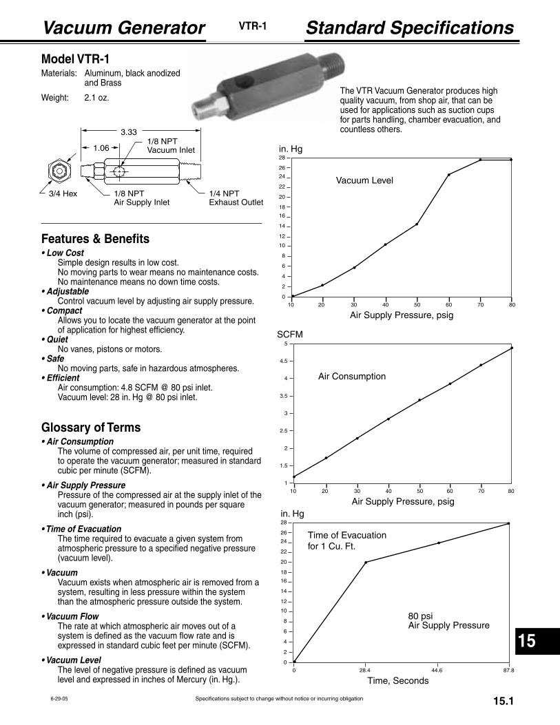
Specifications subject to change without notice or incurring obligation
15
15.16-29-05
VTR-1
Features & Benefits
Simple design results in low cost.No moving parts to wear means no maintenance costs.No maintenance means no down time costs.
Control vacuum level by adjusting air supply pressure.
Allows you to locate the vacuum generator at the pointof application for highest efficiency.
No vanes, pistons or motors.
No moving parts, safe in hazardous atmospheres.
Air consumption: 4.8 SCFM @ 80 psi inlet.Vacuum level: 28 in. Hg @ 80 psi inlet.
Glossary of Terms
The volume of compressed air, per unit time, requiredto operate the vacuum generator; measured in standardcubic per minute (SCFM).
Pressure of the compressed air at the supply inlet of thevacuum generator; measured in pounds per squareinch (psi).
The time required to evacuate a given system fromatmospheric pressure to a specified negative pressure(vacuum level).
Vacuum exists when atmospheric air is removed from asystem, resulting in less pressure within the systemthan the atmospheric pressure outside the system.
The rate at which atmospheric air moves out of asystem is defined as the vacuum flow rate and isexpressed in standard cubic feet per minute (SCFM).
The level of negative pressure is defined as vacuumlevel and expressed in inches of Mercury (in. Hg.).
Model VTR-1Materials: Aluminum, black anodized and Brass
Weight: 2.1 oz.
0
2
4
6
8
10
12
14
16
18
20
22
24
26
28
10 20 30 40 50 60 70 80
Vacuum Level
in. Hg
Air Supply Pressure, psig
1
1.5
2
2.5
3
3.5
4
4.5
5
10 20 30 40 50 60 70 80
Air Consumption
SCFM
Air Supply Pressure, psig
0
2
4
6
8
10
12
14
16
18
20
22
24
26
28
0 28.4 44.6 87.8
Time of Evacuationfor 1 Cu. Ft.
in. Hg
Time, Seconds
80 psi Air Supply Pressure
The VTR Vacuum Generator produces high quality vacuum, from shop air, that can be used for applications such as suction cups for parts handling, chamber evacuation, and countless others.3.33
3/4 Hex
1.06
1/4 NPTExhaust Outlet
1/8 NPTAir Supply Inlet
1/8 NPTVacuum Inlet

16
Hard Wired Connectors 53 & 58 Style Solenoids
How to Order
Connector Type122 = Mini-DIN192 = Micro-DIN
Wire Direction J = 90° styleF = Straight style
Wire Length6 = 6 foot
Contacts4 = dual ground (192-J and 192-F only) 0 = ground down (122-J and 122-F only)1 = ground up (122-J only)
Operating Voltage / Housing00 = 250VAC 50/60Hz, 300VDC. No light, black housing. No suppression.
25 = 6-24 VAC/VDC 50/60 Hz. Lighted, translucent housing. Metal oxide varistor (MOV) suppression.
55 = 48-120 VAC/VDC 50/60 Hz, Lighted, translucent housing. Metal oxide varistor (MOV) suppression.
85 = 208-240 VAC 50/60 Hz, Lighted, translucent housing. Metal oxide varistor (MOV) suppression.
– – Part Number
Ordering Examples
192-J64-00 Micro-DIN connector, 90° wire direction, 6 foot wire, dual ground, 250 VAC 50/60Hz, 300VDC, no light, black housing, no suppression.
122-F60-25 Mini-DIN connector, straight wire direction, 6 foot wire, ground down, 6-24 VAC/VDC 50/60 Hz, lighted, translucent housing, metal oxide varistor suppression.
The Fabco-Air all-molded DIN solenoid valve connector/gasket/cord assembly
offers a completely molded design that is far better for environmental integrity
than field wired versions. The integrated gasket design boasts IP67/NEMA 6
rating and makes it impossible to lose the gasket.
16.13-13-08Specifications subject to change without notice or incurring obligation
Choose From TheseAvailable Models
122-F60-00122-F60-25122-F60-55122-F60-85
122-J60-00122-J60-25122-J60-55122-J60-85
122-J61-00122-J61-25122-J61-55122-J61-85
192-F64-00192-F64-25192-F64-55
192-J64-00192-J64-25192-J64-55

16
Hard Wired Connectors 53 & 58 Style Solenoids
40
25.5
4.0M3
28
21 11
4.0M3
48.5
25.5
J Style 90° Connectors
F Style Straight Connectors
122 Mini-DIN 192 Micro-DIN
Wiring Information
122 Type Connector
192 Type Connector
192 Type Connector
122 Type Connector
Technical Data
18 gauge standard for 122 Mini DIN.
20 gauge standard for 192 Micro DIN.
impossible to lose.
–13°F to 176°F (–25°C to 80°C).
translucent housing after prolonged
exposure to UV rays.
Both connector styles have captive stainless steel screw for mounting interface to solenoid valve. Low profile allows use where space is tight. Molded-in gasket is impossible to lose.
16.23-14-08 Specifications subject to change without notice or incurring obligation
192-J64-25Shown Right
122-J61-00 Shown Left
192-F64-00 Shown Right
122-F60-55 Shown Left

6
Specifications subject to change without notice or incurring obligation
Cylinders, Valves, & Accessories
Notes