FAARFIELD 1.41 Federal Aviation - icao.int · XIII ALACPA Seminar on Airport Pavements Panama City...
45
Presented to: By: Date: Federal Aviation Administration FAARFIELD 1.41 Updates to FAA Advisory Circular 150/5320-6 XIII ALACPA Seminar on Airport Pavements Panama City David R. Brill, P.E., Ph.D. 1 December 2016
Transcript of FAARFIELD 1.41 Federal Aviation - icao.int · XIII ALACPA Seminar on Airport Pavements Panama City...

Presented to:
By:
Date:
Federal AviationAdministrationFAARFIELD 1.41
Updates to FAA Advisory
Circular 150/5320-6
XIII ALACPA Seminar on Airport Pavements
Panama City
David R. Brill, P.E., Ph.D.
1 December 2016

Federal AviationAdministration
2
• Research conducted at the FAA
William J. Hughes Technical Center,
Atlantic City, NJ, USA.
• Sponsor: FAA Office of Airport
Safety and Standards (AAS100),
Washington, DC.
• Provide support for development of
FAA pavement standards (Advisory
Circulars).
Federal Aviation Administration Airport Technology R&D Program
1 December 2016 FAARFIELD 1.41 - AC 150/5320-6F

Federal AviationAdministration
FAA Airport Pavement R&D
1 December 2016 FAARFIELD 1.41 - AC 150/5320-6F 3
National Airport Pavement
Test Facility (NAPTF)
National Airport Pavement
Materials Research Center
(NAPMRC)
Opened August 27, 2015Fully enclosed facility for
accelerated traffic testing of
airport pavements – opened 1999
Heavy Vehicle Simulator for
Airports (HVS-A)
Federal AviationAdministration
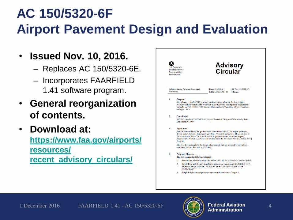
AC 150/5320-6F
Airport Pavement Design and Evaluation
• Issued Nov. 10, 2016.
– Replaces AC 150/5320-6E.
– Incorporates FAARFIELD
1.41 software program.
• General reorganization
of contents.
• Download at:https://www.faa.gov/airports/
resources/
recent_advisory_circulars/
1 December 2016 FAARFIELD 1.41 - AC 150/5320-6F 4

Federal AviationAdministration
AC 150/5320-6F –
Partial List of Changes - General
• Eliminated separate chapter for light-load design
(intended to handle aircraft under 13,600 kg / 30,000
lbs. gross weight).
• Consolidated list of minimum thicknesses
applicable for various standard layer types.
• New guidance for automated compaction criteria –
replaces Table 3-4 in old AC.
• Revised shoulder design criteria.
• Updated all design examples.
• Added appendix on NDT methods for pavement
evaluation.
1 December 2016 FAARFIELD 1.41 - AC 150/5320-6F 5

Federal AviationAdministration
AC 150/5320-6F –
Partial List of Changes - Flexible
• Clarified subgrade characterization using CBR.
• Implemented new asphalt fatigue criteria (RDEC
energy model).
• Reduced minimum base thickness requirements.
– Removed previous requirement for additional stabilized base
thickness (above 125 mm / 5 inches) when P-209 subbase is
used.
1 December 2016 FAARFIELD 1.41 - AC 150/5320-6F 6

Federal AviationAdministration
AC 150/5320-6F –
Partial List of Changes - Rigid
• Modified conversion from CBR to k-value.
• Modified guidance for concrete design strength.
• Added detail on reinforcement at Type A1 joints
(reinforced isolation joint).
• Added detail of transition between PCC and HMA
Pavement sections.
• Removed CRCP design procedure (rarely used).
• Reduced subgrade compaction requirements for
rigid pavements.
1 December 2016 FAARFIELD 1.41 - AC 150/5320-6F 7

Federal AviationAdministration
AC 150/5320-6F Organization
• Chapter 1: Airport Pavement
Function and Purpose
– Pavement layers & specifications
– Cost effectiveness analysis
• Chapter 2: Soil Investigations
– Soil strength testing
– Subgrade stabilization
• Chapter 3: Pavement Design
– Flexible Pavement Design
– Rigid Pavement Design
• Chapter 4: Pavement
Rehabilitation (includes
overlay design)
• Chapter 5: Pavement Structural
Evaluation
• Chapter 6: Pavement Design
for Shoulders
• Appendix A: Soil
Characteristics (USC Classification)
• Appendix B: Design of
Structures
• Appendix C: NDT Using
Falling-Weight Type Devices
• Appendix D: Reinforced
Isolation Joint
• Appendix E: Variable Section
Runway
• Appendix F: Related Reading
Material
1 December 2016 FAARFIELD 1.41 - AC 150/5320-6F 8

Federal AviationAdministration
Chapter 3 – Pavement Design
1. Design Considerations
2. FAA Pavement Design
3. Flexible Pavements
4. Full Depth Asphalt
Pavements
5. Rigid Pavements
6. Stabilized Base Course
7. Base/Subbase
Contamination
8. Drainage Layer
9. Subgrade Compaction
10. Swelling Soils
11. Pavement Life
12. Pavement Design Using
FAARFIELD
13. Flexible Pavement Design
14. Rigid Pavement Design
15. Pre-stressed, Precast,
Reinforced & CRCP
16. Aggregate-Turf Pavements
17. Heliport Design
18. Passenger Loading Bridge
1 December 2016 FAARFIELD 1.41 - AC 150/5320-6F 9
NOTE: No more separate chapter for
light load aircraft design.

Federal AviationAdministration
Layer Types & Allowable Modulus Values
• Similar to FAARFIELD v
1.305.
• “Undefined” layer replaced
by “User-defined.”
• P-306 econocrete renamed
Lean Concrete.
• Added P-219, recycled
concrete aggregate, as a
standard layer type.
• Rubblized concrete base
now handled as user-
defined layer.
1 December 2016 FAARFIELD 1.41 - AC 150/5320-6F 10

Federal AviationAdministration
Minimum Layer Thickness - Flexible
1 December 2016 FAARFIELD 1.41 - AC 150/5320-6F 11

Federal AviationAdministration
Minimum Layer Thickness - Rigid
1 December 2016 FAARFIELD 1.41 - AC 150/5320-6F 12

Federal AviationAdministration
FAARFIELD 1.41
• Accompanies new AC
150/5320-6F.
• Many significant changes.
• Reduces excess design
conservatism.
• New design-based
compaction procedure.
• Incorporates results of full-
scale tests at the National
Airport Pavement Test
Facility.
• Download:
1 December 2016 FAARFIELD 1.41 - AC 150/5320-6F 13
http://www.airporttech.tc.faa.gov/Download/Airport-Pavement-Software-Program

Federal AviationAdministration
Federal
Aviation
Administration
Rigid and
Flexible
Iterative
Elastic
Layered
Design
• FAARFIELD is the standard FAA airport pavement thickness design program.
• FAARFIELD design procedure for:– Flexible
– Rigid
– Overlay
• Current version is FAARFIELD 1.41 (posted 10 Nov 2016)
FAARFIELD – What Is It?
1 December 2016 FAARFIELD 1.41 - AC 150/5320-6F 14

Federal AviationAdministration
FAARFIELD – Technical Background
• Computer program for Windows operating systems.
• Main program drives three subprograms:– LEAF (layered elastic analysis).
– NIKE3D (3D finite element analysis).
– FAAMesh (3D mesh generation).
• NIKE3D information:– Modified for FAARFIELD by the FAA.
– Distributed in compiled form under a software sharing agreement with Lawrence Livermore National Laboratory (LLNL).

Federal AviationAdministration
Structural Models in FAARFIELD
• Both layered elastic (LEAF)
and 3D-FEM (NIKE3D) are
used in FAARFIELD.
• Flexible pavement design
– LEAF is used for all structural
computations.
– For flexible, no advantage to
using 3D-FEM.
• Rigid pavement design
– LEAF is used to generate a
preliminary thickness.
– Final iterations are done
using a 3D finite element
model (3D-FEM).
q
2a
h1
h2
E1, 1
E2, 2
E3, 3
q
2a
h1
h2
E1, 1
E2, 2
E3, 3

Federal AviationAdministration
Cumulative Damage Factor (CDF)
• Sums the damage contributed from each aircraft -not from equivalent aircraft.
• CDF = (ni /Ni), where:– ni = actual passes of individual aircraft i
– Ni = allowable passes of individual aircraft i
• When CDF = 1, design life is exhausted.
• In FAARFIELD:– The gear location and wander are considered separately for
each aircraft in the total mix.
– CDF is calculated for each 25.4 cm (10 inch) wide strip over a total 20.83 m (820 inch) width.
– Miner’s rule to sum damage for each strip.
• Must input the fleet mix, NOT equivalent departures of design aircraft.
1 December 2016 FAARFIELD 1.41 - AC 150/5320-6F 17

Federal AviationAdministration
Cumulative Damage Factor (CDF)C
DF
Difference in Gear
Location
25.4 cm (10 in.)
Damage from
Airplane A
Damage from
Airplane B
1 December 2016 FAARFIELD 1.41 - AC 150/5320-6F 18

Federal AviationAdministration
Cumulative Damage Factor (CDF)
25.4 cm (10 in.)
CD
F
Damage from
Airplane A
Damage from
Airplane B
Total Damage
1 December 2016 FAARFIELD 1.41 - AC 150/5320-6F 19

Federal AviationAdministration
Large Airplane Traffic Mix Gear
Locations
0 25 50 75 100 125 150 175 200 225 250 275 300 325 350 375 400
Distance From Centerline (in)
Ru
nw
ay C
en
terl
ine .
B-777-200
B-747-400
A-330
B-767-200
A-300-B2
B-757
B-727
B-737-400
MD-83
MD-90-30
DC-9-50
DW 100,000
Regional Jet 700
Regional Jet 200
DW 45,000
DW 30,000
SW 30,000
1 December 2016 FAARFIELD 1.41 - AC 150/5320-6F 20

Federal AviationAdministration
FAARFIELD – CDF Graphical Display
1 December 2016 FAARFIELD 1.41 - AC 150/5320-6F 21

Federal AviationAdministration
Remember - in FAARFIELD
Use the entire traffic mix!
=
1 December 2016 FAARFIELD 1.41 - AC 150/5320-6F 22

Federal AviationAdministration
FAARFIELD 1.41 – What’s New?
General Improvements:
• Updated aircraft library aligned with COMFAA 3.0.
• Added non-aircraft vehicles (trucks) to library.
• Automatically generates PDF design report.
• Automated, software-based compaction criteria.
• Support for user-defined gear configurations.
• All data files now stored in document directories.
• Minimum thickness in convenient metric units (100
mm; 125 mm)
• Updated Help file with new examples.
1 December 2016 FAARFIELD 1.41 - AC 150/5320-6F 23
Federal AviationAdministration
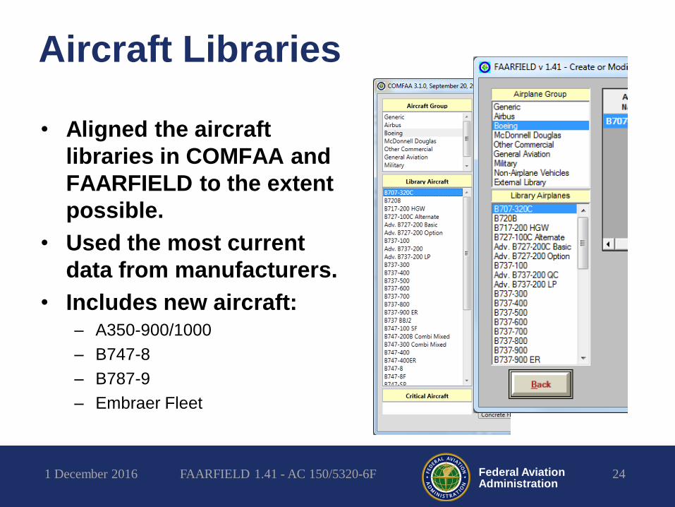
Aircraft Libraries
• Aligned the aircraft
libraries in COMFAA and
FAARFIELD to the extent
possible.
• Used the most current
data from manufacturers.
• Includes new aircraft:– A350-900/1000
– B747-8
– B787-9
– Embraer Fleet
1 December 2016 FAARFIELD 1.41 - AC 150/5320-6F 24

Federal AviationAdministration
Automated Compaction Criteria
25
Computes compaction control points for rigid & flexible pavements.
1 December 2016 FAARFIELD 1.41 - AC 150/5320-6F

Federal AviationAdministration
Changes in Data File Storage
• All data files are now stored in document
directories by default.
– Job files
– External aircraft library files
– Output files.
– C:\Users\[User Name]\Documents\FAARFIELD
• Previously, data files (including job files)
were stored in the program directory.
– Required unrestricted read/write access for user.
– Risk of data loss when changing/upgrading PC.
1 December 2016 FAARFIELD 1.41 - AC 150/5320-6F 26

Federal AviationAdministration
FAARFIELD 1.41 – What’s New?
Flexible Designs:
• Revised flexible failure model now includes direct
evaluation of tandem gear damage.
• Advanced, energy-based asphalt fatigue models.
Fatigue damage (HMA CDF) is now computed at the
bottom of all asphalt layers.
• Reduced excess stabilized base thickness
requirement.
• Automatic base layer thickness design feature
extended to all standard flexible pavement designs.
• Improved sublayering of aggregate layers.
1 December 2016 FAARFIELD 1.41 - AC 150/5320-6F 27

Federal AviationAdministration
Flexible Pavements
28
Conventional Flexible Pavement
Comparison
Stabilized Flexible Pavement
Comparison
• New thickness designs are generally less conservative than
FAARFIELD 1.305 designs for the same inputs.
• More compatible with COMFAA 1.3 (ACN-PCN method).
1 December 2016 FAARFIELD 1.41 - AC 150/5320-6F

Federal AviationAdministration
New Aggregate Modulus Model
• FAARFIELD 1.4 implements
a new sublayering and
modulus computation
procedure for aggregate
subbase (P-154 & P-209).
• Why?
– Previous procedure (WES
Modulus subroutine) has gaps
that can cause illogical results
under some circumstances.
– New model provides a continuous
function of modulus with changes
in P-154 thickness.
– Better overall agreement with the
P-209/P-154 equivalency factor
used in PCN computations.

Federal AviationAdministration
Flexible Base Thickness
• The minimum stabilized
base thickness is still
5 in.
• No additional stabilized
base thickness requirement
when improved subbase
material (P-209) is used.
• Additional thickness
requirement applies only if
standard subbase (P-154) is
used.
1 December 2016 FAARFIELD 1.41 - AC 150/5320-6F 30

Federal AviationAdministration
Direct Evaluation of Tandem Gear Damage
(Flexible)
• Old method was a two-part
P/C ratio consisting of a
wander-related factor
multiplied by a tandem factor.
• New method: Compute CDF
for multiple wheels in tandem
by numerical integration of
the longitudinal strain profile.
• Similar to method used in
Alizé-LCPC (DGAC-France).
• New P/C ratio relates only to
wander.
1 December 2016 FAARFIELD 1.41 - AC 150/5320-6F 31
Old Method
New Method

Federal AviationAdministration
FAARFIELD 1.41 – What’s New?
Rigid Designs:
• Completely revised rigid failure model based on
newest full-scale test data.
• Design stress is the larger of interior stress or 3D
finite element computed edge stress (reduced by
25% for assumed load transfer).
• Completely rewritten concrete overlay design
procedure.
• Improved, more accurate 3D finite element model.
• New Visual Basic.NET mesh generation procedure
replaces legacy Fortran code.
1 December 2016 FAARFIELD 1.41 - AC 150/5320-6F 32

Federal AviationAdministration
Rigid Pavements
33
Effect of Subgrade Modulus E Rigid Design Example
• New thickness designs are generally less conservative than
FAARFIELD 1.305 designs for the same inputs.
• New calibrations incorporate CC6 failure data.
1 December 2016 FAARFIELD 1.41 - AC 150/5320-6F

Federal AviationAdministration
Improved Rigid Failure Model
34
Effect of Concrete Flex Strength Effect of Traffic
• Sensitivity to factors such as concrete strength, traffic level and
subgrade support is similar to current version.
0
2
4
6
8
10
12
14
16
18
20
0.01 0.1 1 10 100C
on
cret
e T
hic
kne
ss, i
n.
Traffic Factor
FAARFIELD 1.305 FAARFIELD 1.41
1 December 2016 FAARFIELD 1.41 - AC 150/5320-6F

Federal AviationAdministration
Improved 3D Finite Element Mesh
1 December 2016 FAARFIELD 1.41 - AC 150/5320-6F 35
FAARFIELD 1.41FAARFIELD 1.305
• More accurate stress results.
• Improved infinite foundation model.
• Still one slab model with assumed 25% load transfer.

Federal AviationAdministration
Rigid Overlay Design Procedure
1 December 2016 FAARFIELD 1.41 - AC 150/5320-6F 36
FAARFIELD 1.305 FAARFIELD 1.41
• Completely rewrote overlay life program module.
• Eliminated gaps and illogical results, especially for
overlays on new or undamaged PCC.

Federal AviationAdministration
FAARFIELD 1.4
System/Software Requirements
Recommended
• Windows 7 or higher
• 3 GHz processor
• 4 GB RAM
• 64-bit operating system*
Minimum
• Windows XP or higher
• 2 GHz processor
• 2 GB RAM
• 200 MB of available space on
hard drive.
Notes:
*FAARFIELD 1.4 supports 32-bit or 64-bit Windows operating systems.
1 December 2016 FAARFIELD 1.41 - AC 150/5320-6F 37

Federal AviationAdministration
Running FAARFIELD: Program Windows and Linkage
STARTUPControl and
Organization
NOTESAdditional Section
Information and
Detailed Output Data
STRUCTUREStructure Data Input
and Design
AIRCRAFTAircraft Load and
Traffic Data Input
AIRCRAFT DATAView Landing Gear
Geometry, Load, and
Tire Pressure
OPTIONSSet User Options
and Tolerances
Export XML
1 December 2016 FAARFIELD 1.41 - AC 150/5320-6F 38

Federal AviationAdministration
FAARFIELD Input Requirements
1 December 2016 FAARFIELD 1.41 - AC 150/5320-6F 39
Structure Window• For each structural layer:
– Material type (FAA specification)
– Layer Thickness
– Modulus or R-value (if applicable)
• There are built-in restrictions on the layer types, including relative position and layer properties.
• For subgrade, can enter CBR or k and FAARFIELD will convert to E.
Aircraft Window• Select airplane from library.
• For each airplane in the mix:
– Aircraft Name
– Gross Taxi Weight
– Annual departures and percent annual
growth if applicable
• Enter data for all airplanes in the mix.

Federal AviationAdministration
FAARFIELD External Airplane Library
• FAARFIELD includes >190 airplanes in the
internal library.
• FAARFIELD allows users to define
additional airplanes in the external library.
• Add or modify external library airplanes by
editing the file: FAAairplaneLibrary.xml
• XML (Extensible Markup Language) format.
• Edit the file using Microsoft Word or other
XML editor.
1 December 2016 FAARFIELD 1.41 - AC 150/5320-6F 40

Federal AviationAdministration
FAARFIELD 1.3 Software Overview
September 13, 2012
Example Airplane Info in XML File
• GrossWt = weight of airplane, lbs.
• MGpcnt = % of GrossWt on 1 main gear
• CP = tire contact pressure, psi
• Gear = gear designation letter code
• IGear = gear ID no. (see next slide)
• TT, TS, TG, B = gear parameters (see Help File)
• NTires = no. of tires in 1 gear
– TX, TY: Enter 1 pair of coordinates for each tire (1 through
NTires), in.
• NEVPTS = no. of evaluation points for LEAF
– EVPTX, EVPTY: Enter 1 pair of x,y coordinates for each
evaluation point (1 through NEVPTS), in.
• Note: You have to enter the data in U.S.
units (inches, psi).

Federal AviationAdministration
Codes for Various Gear Types
1 December 2016 FAARFIELD 1.41 - AC 150/5320-6F 42
Gear Type Example Code ID No.
S DC3 B 2
D B737 D 3
2D B767 F 3
3D B777 N 3
User-Defined* A380 (20 wheels) X 13
*See help file for information on user-defined gear geometries.

Federal AviationAdministration
User-Defined Gear Geometries
• A new feature allows users
to specify arbitrary gear
geometries in the external
library.
– Coded as “X” in the external
library.
– Allows multiple wheel groups to
be defined.
• Uses rewritten internal
pass/coverage computation
routine.
• New user guidance for the
external library – see
FAARFIELD Help File.
1 December 2016 FAARFIELD 1.41 - AC 150/5320-6F 43
Wheel
Group
In this example, the externally defined A380
main gear gives the identical result as the
internally stored airplane.

Federal AviationAdministration
Further Improvements
• Modernize the
FAARFIELD graphical
user interface (GUI).
– Job and section entry.
– Improved start-up screen.
– Improved screen re-sizing
and appearance.
– Improved flow between
screens.
• Rationalize data file
structure.
1 December 2016 FAARFIELD 1.41 - AC 150/5320-6F 44

Federal AviationAdministration
Thank You! ¡Gracias!
45
http://www.airporttech.tc.faa.gov/
1 December 2016 FAARFIELD 1.41 - AC 150/5320-6F
Acknowledgments:
FAA Airport Technology R&D Branch:
Dr. Michel Hovan, Branch Manager;
Jeff Gagnon, Airport Pavement Section Manager;
Dr. Navneet Garg; Al Larkin; Murphy Flynn; Ryan Rutter; Quinn Jia, Wilfredo Villafane
FAA Airport Engineering Division:
Doug Johnson; Greg Cline
SRA International:
Michael Collins; Dr. Izydor Kawa; Dr. Qiang Wang; Dr. Yuanguo Chen; Dr. Kairat Tuleubekov; Shawn
Hershman; Jeff Stein
Gemini:
Dr. Hao Yin