
FA6B - Muncie Power Products
32
Muncie Power Products, Inc. FA6B PTO INSTALLATION AND OPERATOR’S MANUAL KEEP IN VEHICLE READ OPERATING INSTRUCTIONS INSIDE BEFORE OPERATING PTO
Transcript of FA6B - Muncie Power Products

Muncie Power Products, Inc.
FA6BPTO INSTALLATION
AND OPERATOR’S MANUAL
KEEP IN VEHICLEREAD OPERATING INSTRUCTIONSINSIDE BEFORE OPERATING PTO
2
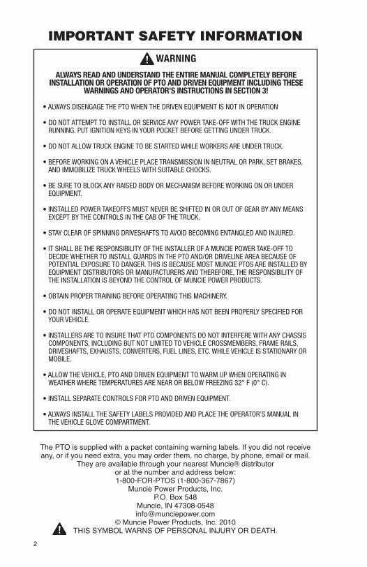
WARNING
ALWAYS READ AND UNDERSTAND THE ENTIRE MANUAL COMPLETELY BEFORE INSTALLATION OR OPERATION OF PTO AND DRIVEN EQUIPMENT INCLUDING THESE
WARNINGS AND OPERATOR’S INSTRUCTIONS IN SECTION 3!
• ALWAYS DISENGAGE THE PTO WHEN THE DRIVEN EQUIPMENT IS NOT IN OPERATION
• DO NOT ATTEMPT TO INSTALL OR SERVICE ANY POWER TAKE-OFF WITH THE TRUCK ENGINE RUNNING. PUT IGNITION KEYS IN YOUR POCKET BEFORE GETTING UNDER TRUCK.
• DO NOT ALLOW TRUCK ENGINE TO BE STARTED WHILE WORKERS ARE UNDER TRUCK.
• BEFORE WORKING ON A VEHICLE PLACE TRANSMISSION IN NEUTRAL OR PARK, SET BRAKES, AND IMMOBILIZE TRUCK WHEELS WITH SUITABLE CHOCKS.
• BE SURE TO BLOCK ANY RAISED BODY OR MECHANISM BEFORE WORKING ON OR UNDER EQUIPMENT.
• INSTALLED POWER TAKEOFFS MUST NEVER BE SHIFTED IN OR OUT OF GEAR BY ANY MEANS EXCEPT BY THE CONTROLS IN THE CAB OF THE TRUCK.
• STAY CLEAR OF SPINNING DRIVESHAFTS TO AVOID BECOMING ENTANGLED AND INJURED.
• IT SHALL BE THE RESPONSIBILITY OF THE INSTALLER OF A MUNCIE POWER TAKE-OFF TO DECIDE WHETHER TO INSTALL GUARDS IN THE PTO AND/OR DRIVELINE AREA BECAUSE OF POTENTIAL EXPOSURE TO DANGER. THIS IS BECAUSE MOST MUNCIE PTOS ARE INSTALLED BY EQUIPMENT DISTRIBUTORS OR MANUFACTURERS AND THEREFORE, THE RESPONSIBILITY OF THE INSTALLATION IS BEYOND THE CONTROL OF MUNCIE POWER PRODUCTS.
• OBTAIN PROPER TRAINING BEFORE OPERATING THIS MACHINERY.
• DO NOT INSTALL OR OPERATE EQUIPMENT WHICH HAS NOT BEEN PROPERLY SPECIFIED FOR YOUR VEHICLE.
• INSTALLERS ARE TO INSURE THAT PTO COMPONENTS DO NOT INTERFERE WITH ANY CHASSIS COMPONENTS, INCLUDING BUT NOT LIMITED TO VEHICLE CROSSMEMBERS, FRAME RAILS, DRIVESHAFTS, EXHAUSTS, CONVERTERS, FUEL LINES, ETC. WHILE VEHICLE IS STATIONARY OR MOBILE.
• ALLOW THE VEHICLE, PTO AND DRIVEN EQUIPMENT TO WARM UP WHEN OPERATING IN WEATHER WHERE TEMPERATURES ARE NEAR OR BELOW FREEZING 32° F (0° C).
• INSTALL SEPARATE CONTROLS FOR PTO AND DRIVEN EQUIPMENT.
• ALWAYS INSTALL THE SAFETY LABELS PROVIDED AND PLACE THE OPERATOR’S MANUAL IN THE VEHICLE GLOVE COMPARTMENT.
The PTO is supplied with a packet containing warning labels. If you did not receive any, or if you need extra, you may order them, no charge, by phone, email or mail.
They are available through your nearest Muncie® distributor or at the number and address below:1-800-FOR-PTOS (1-800-367-7867)
Muncie Power Products, Inc.P.O. Box 548
Muncie, IN [email protected]
© Muncie Power Products, Inc. 2010THIS SYMBOL WARNS OF PERSONAL INJURY OR DEATH.
IMPORTANT SAFETY INFORMATION

3
TABLE OF CONTENTS
DESCRIPTION PAGE
Important Safety Information ............................................................................. 2
Section 1 – PTO Installation
FA6B PTO Installation Instructions ................................................................... 4
FA6B PTO Installation - A67 ............................................................................. 6
FA6B PTO Installation - I84 .............................................................................. 8
FA6B PTO Activation Installation .....................................................................11
FR66 Direct Couple Hydraulic Pump Installation ............................................ 13
Section 2 – Wiring Diagrams and Auxiliary Wiring Instructions
FA6B Feature Option “H” - A67/I84 ................................................................. 15
FA6B Feature Option “B” - I84 ........................................................................ 15
FA6B Installation With SPD-1001D ................................................................. 16
Section 3 – Activation Kit Diagram
FA6B Shift Option “H” – A67 Activation Diagram ............................................ 17 FA6B Shift Option “B” – I84 Activation Diagram .............................................. 18
FA6B Shift Option “H” – I84 Activation Diagram ............................................. 19
FA6B Shift Option D - I84 Activation ............................................................... 20
FA6B PTO Testing Procedure ......................................................................... 21
Section 4 – Operator’s Manual
PTO Shifting Procedures & Precautions ......................................................... 22 PTO Operation ................................................................................................ 22
PTO Maintenance ........................................................................................... 23
PTO Torque & Horsepower Ratings ................................................................ 23
PTO Troubleshooting Guide ........................................................................... 24 Power Take-Off Warranty ................................................................................ 25

4
SECTION - 1 PTO INSTALLATIONALL INSTALLERS MUST READ THE FOLLOWING
PTO AND ACTIVATION KIT INSTALLATION INSTRUCTIONSAlways wear safety glasses. Read entire manual before starting installation.
IMPORTANT: Disconnect vehicle battery prior to installing electrical and electric/hydraulic activation kits.
A.Vehiclemanufacturersmayhavespecificlocationsforaccessingelectrical power and activating hydraulics. The body builder manual or company representative for the vehicle chassis should be contacted prior to installing electrical or hydraulic systems.
B. Route wires and activation lines away from rotating and high temperature components.Useappropriateloomsandbulkheadpass-thru’swhereverpossible to avoid rubbing through insulation or tubing and causing an electrical short or oil leak.
C. Follow all Federal Motor Vehicle Safety Standards (FMVSS) for your vehicle.
D. Where electrical grounds are indicated, be sure that they are good grounds, with straight paths to the vehicle battery ground. (Many vehicle cabs are insulated from the vehicle frame and a weak ground is a very common cause for malfunctions).
E. When installing hydraulic components, be certain to follow common installation and testing procedures. If you are not familiar with acceptable installation procedures request instructions and guidance from the hydraulic equipment supplier.
F. Caution should be taken by installer with any PTO installation to insure components do not interfere with any chassis component during installation or when vehicle is operated.
G. Cold weather start conditions require that the transmission be started and warmed prior to engaging PTO and using equipment. Hydraulic pumps should be run at idle and under no load conditions to allow oil to warm before activating ‘ hydraulicsystem.
IMPORTANT INFORMATION:There is valuable information contained in the Body Builders Layout Book”. You can
obtainacopyofthisbookbygoingtothechassismanufacturer’swebsiteathttp://www.fleet.ford.com/truckbbas/

5
INSTALLATION INSTRUCTIONSAlways wear safety glasses. Read entire manual before starting installation.
1. There is a packet with the FA6B PTO which contains four (4) warning labels. Before adhering the labels, make sure the surfaces are free of dirt and grease. Place the labels supplied with the FA6B as follows:
Truck Frame LabelsThe two (2) Truck Frame Labels, which measure approximately 4" x 8", are to be placed on the outside of the vehicle frame rail. These labels are to be easily seen by anyone who might go under the truck or near the FA6B PTO. One label is to be placed oneachsideofthevehicle.Seefigure1.
Note: Should the vehicle body installed on the chassis cover the frame rail, place the label on the body in a position easily visible by anyone who might go under the vehicle or near the FA6B PTO. Do NOT paint over the labels.
Visor and Dash LabelsThe PTO Equipped Caution Label, which measures approximately 2" x 3", is to be placed within the cab of the vehicle and in easy view of the vehicle operator. It should be located near the PTO control, when the control is installed in the vehicle dash (see figure2).ThislabeldirectstheoperatortoreadthePTOoperatinginstructionsontheVisor Label. The Visor Label, which measures approximately 3½" x 6", is to be placed onthevisorontheoperator’ssideofthevehicle.Ifusingdual-mode,placethefifthlabelnexttothevisorlabel.Seefigure2below.
2. While seated in the vehicle and with the transmission in “Neutral”, start the engine and listen to the sounds of both the transmission and the engine before installing the FA6B PTO. A noise in the transmission gear may be more noticeable after the FA6B PTO is installed. Next, we will begin the installation of the FA6B PTO, STOP ENGINE!
Figure 1
Part No. 36T38634 © Muncie Power Products, Inc. 2006
LO
CA
TE
ON
VIS
OR
SO
IT IS
VIS
IBL
E W
HE
N T
HE
SU
N V
ISO
R IS
RA
ISE
D
UNDERSTAND THIS LABEL BEFORE USING POWER TAKE-OFF (PTO). Refer to Owner's Manual in glove box or on the internet at: www.munciepower.com
HOW TO USE THEPOWER TAKE-OFF (PTO)
STATIONARY APPLICATIONS:CHOCK WHEELS BEFOREENGAGING PTO.
Manual Shift PTOs (including Air Shift)Manual Transmissions
1. Push in clutch pedal.2. Shift transmission into
neutral.3. Engage PTO.4. Let clutch pedal out.
Manual Shift PTOs (including Air Shift)Automatic Transmissions
1. Let engine idle.2. Apply brakes, while seated
in driver's seat.3. Place shift selector in any
drive range.4. Engage PTO.5. Shift transmission to
neutral or park.
Power Shift PTOsManual or Automatic Trans.
1. Let engine idle.2. Engage PTO with switch.3. Resume operating speed.
NEVER GET UNDER THIS TRUCK IF THE ENGINE IS RUNNING!Hands, clothes, hair, etc. can get caught on spinning shafts and U-joints.
LEA Y COMPRENDE ESTA CALCOMANÍA ANTES DE USAR LA TOMA DE FUERZA. Véase el manual del
usuario. Visite el sitio www.munciepower.com
COMO USAR LATOMA DE FUERZA
APLICACIONES ESTACIONARIAS: BLOQUEAR LAS LLANTAS ANTES DE ACTIVAR LA TOMA DE FUERZA.
Tomas de fuerza de activación manual(incluye activación neumática)Transmisiones estándaresl
1. Pise el embrague2. Cambie la transmisión
a neutral 3. Activa la toma de fuerza4. Desembragar
Transmisiones automáticas1. Prende el motor. No aumenta
velocidad o RPM 2. Frene mientras está sentado en
la silla del conductor 3. Cambia la transmisión a marcha
(cualquier velocidad) 4. Activa la toma de fuerza 5. Cambia la transmisión a neutral
o aparcamiento
Tomas de fuerza de activación con embragueTransmisiones estándares o automáticas
1. Prende el motor. No aumenta velocidad o RPM
2. Activa la toma de fuerza con el interruptor 3. Aumenta las RPM a la velocidad de
operación deseada
YOU MAY BE HURT OR KILLED.It is against Federal Law to try to fix PTO driven machinery if the engine is running. Always turn the engine off. Then, put the keys in your pocket. (OSHA 1910.147)
¡NUNCA SE META DEBAJO EL CAMIÓN CUANDO EL MOTOR ESTÉ EN MARCHA! Cuídese las manos, la ropa, el pelo, etc. cuando la flecha cardán está girando.
PUEDA LASTIMARSE O SER MUERTO. Está en contra de leyes federales intentar arreglar el equipo manejado por la toma de fuerza cuando el motor está en marcha. En todas circunstancias sin excepción, apague el motor y ponga las llaves en su bolsillo.
(OSHA 1910.147)
THIS VEHICLE IS
EQUIPPED WITH APOWER TAKE-OFF
READ AND UNDERSTAND OPERATOR'S MANUAL
BEFORE USING THIS MACHINE.
FAILURE TO FOLLOW OPERATING
INSTRUCTIONS COULD RESULT IN DEATH OR
SERIOUS INJURY.
ESTE VEHICULO ESTAEQUIPADO CON UNA
TOMA DE FUERZA
IMPORTANTE. FAVOR DE LEER Y CONSULTAR EL MANUAL DE
OPERACION ANTES DE OPERAR Y MANEJAR ESTA UNIDAD.
EL NO SEGUIR LAS INSTRUCCIONES DE
OPERACION PUEDA RESULTAR EN HERIDAS PERSONALES
O EN LA MUERTE.
CO
LOQ
UE
LA C
ALC
OM
AN
IA C
ER
CA
DE
LO
S C
ON
TR
OLE
S D
E LA
TO
MA
DE
FU
ER
ZA
LOC
ATE
VIS
IBLE
AN
D N
EA
R P
TO
CO
NT
RO
L
© Muncie Power Products, Inc. 2006 Part No. 36M35652 (Rev. 9-06)
➡
➡Figure 2

43T36445Elbow Fitting
(optional for clearance)
45T3627428" Hose Assy (JIC-JIC)
4 Locations
43T36431Straight Fitting
6
Allison Automatic Transmission1000 & 2000 Series
3. Remove the cover plate and the cover gasket from the transmission. Discard the gasket as it will not be used again.
Note:DoNOTdrainthetransmissionfluid, but be prepared for a small amount of oil to escape from the PTO opening (avoid contact with this oil because it may be HOT).
4. Clean the mounting pad and inspect the bolt holes in aperture for thread sealant used on OEM bolts. Clean these internal threads with a wire brush to clear out any material.
5. Check the transmission for proper PTO driver gear and location. Also, check the FA6B PTO driver gear for condition. A nick or blemish may cause excessive noise when the FA6B PTO is mounted.
6. Locate the transmission main pressure port(seefigure4).Removetheinstallationkit(43TK5282) components from the FA6B PTO carton.Locatethestraightfitting(43T36431)andtheelbowfitting(43T36445).
7.Installthestraightfitting(O-Ringendfirst)intothe main pressure port located on the left side of the transmission. This port is the second port midway up the side of the transmission. Next, install the elbow fittingontotheotherendofthestraightfittingand position towards the rear of the vehicle. 8. Locate the 28" JIC-JIC swivel hose (45T36274) and installoneendofthehoseontotheelbowfitting installed in the previous step. Route the hose to clear any interference with the transmission or its components.
9.LocatethetransmissionPTOpressurelubricationport(seefigure4).Locatetheteefitting(sold separately – see note below) and plug one of the 1⁄8"NPTportsandinsertthestraightfitting(includedwithteefitting)intotheotherend.Disconnectthecoolinglinefromthecoolerportandinserttheteefitting(O-Ringendfirst)intothetransmission.Connectthecoolinglinetotheendoftheteefitting.
Note: Tee or tap into the Return Cooler Port for the PTO pressure lubrication:GM C3500 cab chassis’ - use 43TK4497 for lubrication line installation*SAE 8–1000Series(#3housing)use43TK5191teefitting*SAE 12 – 1000/2000 Series (#2 housing) use 43TK5157 tee fitting*
*Fitting kits sold separately
BOTTOM VIEW
Main Pressure Port "P": 100-260 PSI 0.44-20 UNF-2A (-4)
Return Cooler Port for PTO Pressure Lubrication
Step Stud20T395291 Location
LubricationPort "B"
InsertCooling
Line
StraightFitting
Plug
Lube HoseAssembly
Tee Fitting
Fig. 3
Fig. 4
Fig. 5
Fig. 6

7
10. Locate the 28” JIC-JIC swivel hose (45T36274) and install one end of the hose ontothestraightfittinginstalledinthepreviousstep.Routethehosetoclearanyinterference with the transmission or its components.
11. Locate the stud kit (20TK5283) provided with the PTO. The kit should include: (5) 12 pt. metric capscrews – 19T37727, (1) step stud – 20T39529 and (1) whiz-lock nut – 22T37605.
12 pt. Metric Capscrew - 5 Step Stud - 1 Whiz-lock Nut - 1
12. Install the (1) step stud into the bottom-center hole location as shown. Place the PTO gasket(s), supplied with the FA6B PTO, over the alignment studandflushagainstthetransmission. The FA6B-A67 uses (1) 13M35092 (0.020") gasket only. The FA6B-I84 uses (2) 13M35092 (0.020") gaskets only.
13. Place the PTO onto the transmission opening while making sure the gasket is stillflushagainstthetransmission.Installthe (5) metric capscrews into the remaining hole locations and torque to 30 ft.lb. Install the whiz-lock nut onto the step stud and torque to 17 ft.lb.
Note: Checking the backlash is not required when using the supplied gasket. Never use silicone type sealant on the PTO/transmission mounting surface, as proper backlash cannot be attained.
Proceed to step 14 on page 10 to continue installation for the FA6B PTO and the Allison transmission
Fig. 7
Fig. 8
Fig. 9

Aisin Automatic TransmissionModels 450-43LE, A443 & A445 5-Speed
A-465 & A460: 6-SpeedFor Model A467, RAM AS69RC, go to page 10
3. Remove the cover plate and the cover gasket from the transmission. Discard the gasket as it will not be used again. Note: Do NOT drainthetransmissionfluid, but be prepared for a small amount of oil to escape from the PTO opening (avoid contact with this oil because it may be HOT).
4. Clean the mounting pad and inspect the bolt holes in aperture for thread sealant used on OEM bolts. Clean these internal threads with a wire brush to clear out any material.
5. Check the transmission for proper PTO driver gear and location. Also, check the FA6B PTO driver gear for condition. A nick or blemish may cause excessive noise when the FA6B PTO is mounted.
6. Locate the transmission main pressure port(seefigure11).Removetheinstallationkit 48TK5472 components from the FA6B PTOcarton.Locatethestraightfitting(43T39222)andtheelbowfitting(43T36445).
7.Installthestraightfitting(O-Ringendfirst)intothe main pressure port located on left side of the transmission. This port is the second port midway up the side of the transmission. Next, install the elbowfittingontotheendofthestraightfittingand position towards the rear of the vehicle.
8. Locate the 28" JIC-JIC swivel hose (45T36274) and install one end of the hose onto the elbow fittinginstalledinthepreviousstep.Routethe hose to clear any interference with the transmission or its components.
9. Locate the transmission PTO lubrication port(seefigure11).Locatethestraightfitting(43T39222)andinsert(o-ringendfirst)intothelubricationport“B”.
10. Locate the 28" JIC-JIC swivel hose (45T36274) and install one end of the hoseontothestraightfittinginstalledinthepreviousstep.Routethehosetoclearany interference with the transmission or its components.
8
43T36445Elbow Fitting
(optional for clearance)
45T3627428" Hose Assy (JIC-JIC)
4 Locations
43T39222Straight Fitting
Lube HoseAssembly
StraightFitting
LubricationPort "P"
Fig. 10
Fig. 11
Fig. 12
Fig. 13

9
11. Locate the stud kit (20TK5169) provided with the PTO. The kit should include: (4) metric studs – 20T37990, (4) spiralock nuts – 22T39282, (2) step stud – 20T41354 and (2) whiz-lock nuts – 22T37605.
Metric Stud-4 Spiralock Nut-4 Step Stud-2 Whiz-lock Nut-2
12. Install the (2) step studs into the top-center hole and the bottom-center hole locations as shown. Next, install the (4) shoulder studs into the remaining hole locations. Place the PTO gasket (supplied with the FA6B PTO) over the alignment studsandflushagainstthetransmission.
13. Place the PTO onto the transmission opening while making sure the gasket is stillflushagainstthetransmission.Installthe (2) whiz-lock nuts onto the (2) step studs and torque to 17 ft.lb. Install the (4) spiralock nuts onto the (4) studs and torque to 40 ft.lb.
Note: Checking the backlash is not required when using the supplied gasket. Never use silicone type sealant on the PTO/transmission mounting surface, as proper backlash cannot be attained.
Proceed to step 14 on page 12 after the Ram Truck installation to continue installation for the FA6B PTO and the Aisin transmission.
Metric Stud
Fig. 14
Fig. 15
Fig. 16

Aisin Automatic TransmissionRAM Truck - AS69RC & A467 6-Speed
3. Remove the cover plate and the cover gasket from the transmission. Discard the gasket as it will not be used again. Note: Do NOT drainthetransmissionfluid, but be prepared for a small amount of oil to escape from the PTO opening (avoid contact with this oil because it may be HOT).
4. Clean the mounting pad and inspect the bolt holes in aperture for thread sealant used on OEM bolts. Clean these internal threads with a wire brush to clear out any material.
5. Check the transmission for proper PTO driver gear and location. Also, check the FA6B PTO driver gear for condition. A nick or blemish may cause excessive noise when the FA6B PTO is mounted.
6. Locate the transmission main pressure port(seefigure18).Removetheinstallationkit 48TK5472 components from the FA6B PTOcarton.Locatethestraightfitting(43T39222)andtheelbowfitting(43T36445).
7.Installthestraightfitting(O-Ringendfirst)intothe main pressure port located at the lower side of the transmission.Next,installtheelbowfittingontothe endofthestraightfittingandpositiontowardsthe rear of the vehicle.
8. Locate the 28" JIC-JIC swivel hose (45T36274) and install one end of the hose onto the elbow fittinginstalledinthepreviousstep.Routethe hose to clear any interference with the transmission or its components.
9. Locate the transmission PTO lubrication port(seefigure20).Locatethestraightfitting(43T39222)andinsert(O-Ringendfirst)intothelubricationport“B”.
10. Locate the 28" JIC-JIC swivel hose (45T36274) and install one end of the hoseontothestraightfittinginstalledin the previous step. Route the hose to clear any interference with the transmission or its components.
10
Main Pressure Port “P”
Port “P”Lube Port
43T36445Elbow Fitting
(optional for clearance)
45T3627428" Hose Assy (JIC-JIC)
4 Locations
43T39222Straight Fitting
Fig. 17
Fig. 18
Fig. 19
Fig. 20

11
11. Locate the stud kit (20TK5169) provided with the PTO. The kit should include: (4) metric studs – 20T37990, (4) spiralock nuts – 22T39282, (2) step stud – 20T41354 and (2) whiz-lock nuts – 22T37605.
Metric Stud-4 Spiralock Nut-4 Step Stud-2 Whiz-lock Nut-2
12. Install the (2) step studs into the top-center hole and the bottom-center hole locations as shown. Next, install the (4) shoulder studs into the remaining hole locations. Place the PTO gasket (supplied with the FA6B PTO) over the alignment studsandflushagainstthetransmission.
13. Place the PTO onto the transmission opening while making sure the gasket is stillflushagainstthetransmission.Installthe (2) whiz-lock nuts onto the (2) step studs and torque to 17 ft.lb. Install the (4) spiralock nuts onto the (4) studs and torque to 40 ft.lb.
Note: Checking the backlash is not required when using the supplied gasket. Never use silicone type sealant on the PTO/transmission mounting surface, as proper backlash cannot be attained.
Proceed to step 14 on page 12 after the Ram Truck installation to continue installation for the FA6B PTO and the Aisin transmission.
Metric Stud
Fig. 14
Fig. 15
Fig. 16

12
14. Locate the solenoid manifold and remove the protective cap plugs. Install the (3) straightthreadelbowfittings(43M68014) into the “IN”, “CL” and “EXH” ports.
15. Install the pressure switch using pipe thread sealant into the port marked “PS”.
16. Remove the protective cap plug from the port located on the bottom of the PTO housing and install the specialorificefitting(43T42012).
17. Remove the protective cap plug from the pressure port located on the rear cover of the FA6B PTO housing and install a straightthreadfitting(43T36431).
18. Remove the protective cap plug from the EXH port located on the rear cover of the FA6B PTO housing and install thestraightfitting(43T37305).
Note:Elbowfitting(43T36445)canbeusedtohelpavoidclearanceissues.Referencefigure3belowforsteps19-22
19.Connectthemainpressurehose(seestep8)totheelbowfitting(43M68014)atthe“IN”port on the solenoid block.
20.Connectthelubricationhose(seestep10)totheelbowfitting(43T42012)installedinstep 16 above.
21. Locate the 28” JIC-JIC swivel hose (45T36274) and install one end of the hose onto thestraightfitting(43T36431)installedinstep17.Connecttheotherendtotheelbowfitting(43M68014) at the “CL” port on the solenoid block.
22. Locate the remaining 28" JIC-JIC swivel hose (45T36274) and install one end of the hoseintotheelbowfitting(43T37385)installedinstep18.Connecttheotherendtotheelbowfitting(43M68014)atthe“EXH”portonthesolenoidblock.
23. Oncealloftheconnectionshavebeenmadeabove,findasuitablelocationforwardofthe PTO housing to mount the activation solenoid.
24. Locate the activation solenoid mounting components in the installation kit provided with the FA6B PTO. The mounting hardwareshould include: (2) capscrews, (2) washers, (2) lock-washers and (2) nuts.
Note: The activation solenoid block assembly mustbespacedoffanyflatsurfaceusing washers to prevent damage to the solenoid.
19T36623Capscrew 21T23153
Flat Washer
21T37991Lock-Washer
22T35140Nut
43T37503Straight Fitting 43T36431
Straight ThreadFitting
1/8" - 27 NPTM7/16" - 20
O-ring Boss
43T36445Elbow Fitting
(optional for clearance)
43T42012Ori�ce Fitting
1/8" - 27 NPTM
Fig. 24
Fig. 25
Fig. 26
Fig. 27

13
25. Route the wire harness from the vehicle front passenger compartment to the solenoid valve.
26.Maketheconnectionstothepressureswitchandtothesolenoidvalve.Seefigure3 for visual.
Note: The solenoid connector is a weather-pack type and the pressure switch is a metri-pack type connector.
27. The wire harness separates at a 4-wire connector.Theconnectorisdesignedtofit through a ⅝" grommet provided. Separate the harness and feed the harness end through the grommet in the passenger barrier. (The Ram Truck installation does not have this connector. see page 22 for wiring connections)
28. Located at the 4-wire connector is a ground lead. Route this lead directly to the battery or battery terminal and ground this terminal.
12V Solenoid Block
30T37954Pressure Switch
43T36431Straight Fitting
43T42012Ori�ce Fitting
43T36445Elbow Fitting
(optional for clearance)
35T37928
43M68014JIC Fitting 90
To Allison/Aisin LubricationPort Fittings
(See Step 9)
To Allison/Aisin MainPressure Port Fittings
(See Step 7)
45T3627428" Hose Assy (JIC-JIC)
4 Locations
43T37503Straight Fitting
INCL
EXH
Weather-PackConnector
Metri-PackConnector
Connect ToWire Harness
Connect ToWire Harness
To Solenoid
To Pressure Switch
Feed this side through Grommet and through wall in engine compartment.
Fig. 28
Fig. 29Fig. 30
Fig. 31

14
29. When routing the wire harness, be sure to tie the harness away from heat sources (exhaust,manifold,etc.)andawayfromrotatingcomponents(driveshaft’s,belts,etc.).
30. Remove the access panel located below the steering wheel.
31. Locate the 4-wire connector (which was fed through the passenger barrier) and connect this connector to the interior half of the PTO harness.
32. Start the truck engine (with the transmission and PTO in neutral) for a few seconds and listen for unnatural noises. Stay clear of rotating components. A PTO will not always make these unnatural noises; should an unnatural noise occur, the shut off the engine and remove the PTO. Examine the PTO and engine for defects.
Caution: Keep the PTO/transmission running time as short as possible.
33.Checkthetransmissionoillevelandfilltotheproperlevel(ifrequired)accordingtotheinstructionsoutlinedinthevehicleoperator’smanual.Runenginefor5-10minutesto check for any leaks. Stay clear of rotating components.
34. Shut off engine. Inspect the capscrews to make sure they are properly tightened. All mounting bolts should be checked on a regular basis (for tightness).
35. If your system contains a drivelinebetween the FA6B PTO and another product and if are experiencing noise in your system that was not heard before, the angularity or phasing of your driveline may be the cause. Check the driveline angularity and reduce the total angularity recommended by the chart and be sure that the PTO shaft is parallel within 1.5° to the pump shaft (or driven unit).
Note: For installations with angles in the top and side views, use this formula to computethetruejointangle(TJA):TJA=√A²+B²
FA6B PTO WITH DIRECT COUPLE HYDRAULIC PUMP INSTALLATION The Muncie PF series hydraulic pumps installed on the 4x4 are of special design. This design allows for interference problems to be minimized.
Before bolting the pump to the FA6B PTO, place a non-seizing compound or grease on the FA6B PTO shaft and pump shaft. Muncie supplied pumps are pre-lubricated and do not require lubrication at installation.
The use of a bracket will be necessary when mounting hydraulic pumps weighing over 30 lbs. (including oil), exceeding 10" in length, or has tandem or multiple sections. These pumps should be mounted using a bracket attached to the rear of the pump and to the transmission to support the pump and to inhibit movement in all directions.
MaxSpeed(RPM)
MaxTJA“A”
3,500 5°
3,000 5°
2,500 7°
2,000 8°
1,500 11°
1,000 12°
Fig. 32
Fig. 33
Fig. 34

15
A bracket attached to two or more transmission bolts is preferred. The bracket design should assure that there is no stress or force exerted on the pump or FA6B PTO shaft during the installation of the bracket.
If vertical supports are greater than 20° off of perpendicular with the transmission main shaft then a reinforced “Z” bracket must be used. Reinforce horizontal members toprohibitflexingatbendorweld.Attachthebracketatthepumpboltclosesttothecenter of gravity of the pump.
Note: When making hydraulic connections to the pump, it is important to route the hydraulic lines away from the front and rear vehicle drive shafts. It is important to route hydraulic lines away from exhaust manifold and pipes.
36. Complete installation by placing warning labels as indicated on borders of the decals. Placement examples are illustrated on page 5.
Fig. 35

16
SECTION 2 – WIRING DIAGRAMS & AUXILIARY WIRING INSTRUCTIONS
FA6B A67/I84 “H” Shift Option Harness
*AllisonTCM(Pin43)-ClutchshiftPTO’srequireaconnectiontotheAllison“PTOEnableInput”circuits.Checkthevehicledealerorbodybuilder’sinformationforthislocation.
FA6B I84 “B” Shift Option Harness
FA6B I84 “D” Shift Option Harness
ACTIVATION SOLENOID
PRESSURE SWITCH
FA6B I84 "D" SHIFT OPTION HARNESS
ABBLACK
VIOLET/YELL
BLACK
PINK/YELL
PINK/YELL
BLACK
VIOLET/YELL
AB
FA6B Wire Harness - 34T43149

17
FA6B PTO INSTALLATION WITH SPD-1001D SYSTEM PROTECTION DEVICE
Requires purchase of SPD-1001D (not included with the FA6B PTO)
A67/I84 Wire Harness - “H” Option
*AllisonTCM(Pin43)-ClutchshiftPTO’srequireaconnectiontotheAllison“PTOEnableInput”circuits.Checkthevehicledealerorbodybuilder’sinformationforthislocation.
** Overspeed Option – Face plate with light access and overspeed light are not included in 30T36270 (12V bracket assembly) and are to be ordered separately in kit 36TK4971.
I84 Wire Harness - “B” Option
12V DC Battery
Ground
Ground
OverspeedLight
To ActivationSolenoid
To PressureSwitch
GreenBlack
RedBlue
Black
Green
Red
Blue
WhiteBlue
RedGreen
Black
Orange
GroundPTO Enable InputWire 143*
33T36299Fuse Assembly
34M18002Butt Splice
34M18250Female Spacle
Connector
Dash Bracket Assembly12V – 30T36270
Detail A
To ActivationSolenoid
To PressureSwitch
Red
Yellow
SPD-1001DGround
Black
GreenX
Blue
Orange(RPM)
White
Blue
Red
Red
34T42079Wire Harness
10-WayConnector
8-WayConnector
OverspeedLight
Ground
RedBlack
YellowGreen
Pink
BlackRed
GreenBlue
Detail A
Blue
From SPD-1001D
1. Cut Yellow Wire2. Connect Blue and Red Wire

18
SECTION 3 – ACTIVATION KIT INSTALLATION
FA6B - A67 “H” Activation Kit – 43TK5282
*Green light in the rocker switch is to turn “ON” when the PTO is engaged and turn “OFF” when the PTO is disengaged.
ITEM QTY PART NO DESCRIPTION
1 1 43T37503 Straight Fitting
2 2 43T36445 Elbow Fitting
3 2 43T36431 Straight Fitting
4 1 43T42012 OrificeFitting
5 4 45T36274 28" Hose Assembly (JIC-JIC)
6 3 43M68014 JIC Fitting 90
7 1 35T37928 12V Solenoid Block
8 1 30T60228 Pressure Switch
9 1 37T35674 Grommet
10 1 34T35872 Wire Harness - A67 “H” Option
11 1 34M18009 Ring Terminal
12 3 34M18250 Female Spade Connector
13 1 33T36299 Fuse Assembly
14 1 36MA1005 Switch Bracket
15 1 36T36271 Face Plate (without light acess)
16 1 30T35687 Rocker Switch
N.S. 1 36MK1007 Dash Bracket Bolt Kit
N.S. 2 19T36623 Capscrew (Solenoid Block)
N.S. 2 21T23153 Flat Washer (Solenoid Block)
N.S. 2 21T37991 Lock Washer (Solenoid Block)
N.S. 2 22T35140 Nut (Solenoid Block)
2
1
5
3
5
7 8
1011
13
12
6CL
IN
EXH
Rocker Switch*
6
Red Black
Green Blue
Green Black
RedBlue
9
12V DC Battery6
LubricationPort Fitting
(Sold Separately)
Main PressurePort Fittings
Weather-PackConnector
Metri-Pack ConnectorType - 280
PTO Enable InputWire 143*
2
3
14
1516
Dash Bracket Assembly12V – 30T36270
(Includes items 14, 15 & 16)

19
FA6B – I84 “B” Activation Kit – 43TK5281
ITEM QTY PART NO DESCRIPTION
1 1 43T37503 Straight Fitting
2 2 43T36445 Elbow Fitting
3 1 43T36431 Straight Thread Fitting
4 2 43T39222 Straight Fitting
5 1 43T42012 OrificeFitting
6 4 45T36274 28" Hose Assembly (JIC-JIC)
7 3 43M68014 JIC Fitting 90
8 1 35T37928 12V Solenoid Block
9 1 30T60228 Pressure Switch
10 1 37T35674 Grommet
11 1 34T42079 Wire Harness - I84 “B” Option
12 1 36MT6818 Female Spade Connector
13 1 32MT2001 Fuse Assembly
N.S. 2 19T36623 Switch Bracket
N.S. 2 21T23153 Face Plate (without light access)
N.S. 2 21T37991 Rocker Switch
N.S. 2 22T35140 Nut (Solenoid Black)
I84 - "B" Option
1
2
3
6
7
7
7
9
6
Metri-Pack ConnectorType - 280
Weather-PackConnector
Dash Light Kit
10
8
Main PressurePort Fittings
LubricationPort Fitting
Red Black
Green Blue
BlackBlack
Black
Red
Yellow
Green
Pink
10-WayConnector
8-WayConnector
2
4
4
34T42079
Wire Harness
13
12

20
FA6B – I84 “H” Activation Kit – 43TK5287
*Green light in the rocker switch is to turn “ON” when the PTO is engaged and turn “OFF” when the PTO is disengaged.
ITEM QTY PART NO DESCRIPTION
1 1 43T37503 Straight Fitting
2 2 43T36445 Elbow Fitting
3 2 43T36431 Straight Fitting
4 1 43T42012 OrificeFitting
5 4 45T36274 28" Hose Assembly (JIC-JIC)
6 3 43M68014 JIC Fitting 90
7 1 35T37928 12V Solenoid Block
8 1 30T60228 Pressure Switch
9 1 37T35674 Grommet
10 1 34T35872 Wire Harness - A67 “H” Option
11 1 34M18009 Ring Terminal
12 3 34M18250 Female Spade Connector
13 1 33T36299 Fuse Assembly
14 1 36MA1005 Switch Bracket
15 1 36T36271 Face Plate (without light acess)
16 1 30T35687 Rocker Switch
17 1 30T35687 Rocker Switch (12V)
N.S. 1 36MK1007 Dash Bracket Bolt Kit
N.S. 2 19T36623 Capscrew (Solenoid Block)
N.S. 2 21T23153 Flat Washer (Solenoid Block)
N.S. 2 21T37991 Lock Washer (Solenoid Block)
N.S. 2 22T35140 Nut (Solenoid Block)
1
2
2
3 6
7
7
8
7
9
6
310 11
12
13
14
4
Weather-PackConnector
Metri-Pack ConnectorType - 280
12V DC Battery
LubricationPort Fitting
Main PressurePort Fittings
Rocker Switch*Red Black
Green Blue
14
1516
Dash Bracket Assembly12V – 30T36270
(Includes items 15, 16 & 17)

21
FA6B-I84 “D” Activation Kit – 48TK5474
ITEM QTY PART NO DESCRIPTION
1 3 43T37503 JIC Adapter
2 2 43T36445 Elbow Fitting
3 2 43T39222 Fitting
4 1 43T36431 Fitting
5 1 43T42012 OrificeElbow
6 3 45T36274 Hose Assembly 28 Inch
7 3 43M68014 Lube Fitting
8 1 35T37928 Valve (12VDC) Block
9 1 30T60228 Pressure Switch
10 1 45T3880 Hose Assembly 36 Inch
11 1 34T43149 2013 Dodge Harnress
N.S. 1 13195 184 “D” Shift Instr
N.S. 2 19T36623 Capscrew
N.S. 2 21T36448 Washer
N.S. 2 21T37991 Lock Washer
N.S. 2 22T35140 Hex Nut, .25-20UNC
N.S. 1 34T36362 Crimp Connector
N.S. 1 36MK3841 Safety Labels
N.S. 1 52MK1000 Gskt./Inst.Pack
N.S. 1 20TK5169 Stud Kit
INCL
EXH
Weather-PackConnector
Metri-PackConnector
Pressure Switch
Solenoid
FA6B-I84 "D" ACTIVATION KIT - 48TK5474
AB
BLACK
VIOLET/YELL
BLACK
PINK/YELL
PINK/YELL
BLACK
VIOLET/YELL
AB
D - HARNESS - 34T43149
2
6
6 6
2
1
34
7
7
79
8
5
310
11
Connections to VSIM are made inside the cab.
Wire Connections in Engine compartment, Grey connector: Pink/Yellow to Pin #2Black to Pin #3Violet/Yellow to Pin #4

22
ELECTRICAL CONNECTIONS
RAM Truck Chassis: The electrical connections for the 2013 and later chassis is different than the previous model years. The PTOs, both the CS6 and the FA6B for 2013, require the shift code “D” to insure the correct wiring harness and these instructions. (For models prior to 2013 follow the instructions for the “B” shift code found in kit 48TK5082.)
The 2013 chassis is provided with a PTO switch on the dash panel located with the other auxiliary switches.
Using the Ram Truck provided switch allows for PTO operation with throttle advance options. The throttle advance is programmed through the Electronic Vehicle Information Center (EVIC) located in the center display. The 2013 & later vehicle is equipped with an electronic control system called the VSIM. The VSIM can be programmed for a single set speed.
Connections to the wiring are made with the Muncie wiring harness PN 34T43149. Connection to our harness is made by using the Ram Truck provided wire leads found in the kit located in the glove box. Three wire leads are used from their kit. These have terminals and seals attached for use in the light gray connector. The gray connector is found in the engine compartment as shown in the photo. Remove the half of the connector with the blanking seals installed. The terminal locations are marked on this connector, remove the blanking seals installed in pin locations 2, 3, & 4 and push the following wire leads into this connector.
Pin #2 Pink/TanPin #3 Black/BrownPin #4 Violet/YellowPin #1 is not used.
Strip the insulation on these leads ½" for connection to the butt splice.Using the Muncie wire harness, connect the wire leads to the appropriate butt splice.
Pin#2 Pink/Tan to Muncie Pink/YellowPin#3 Black/Brown to Muncie BlackPin#4 Violet/Yellow to Muncie Violet/Yellow

23
Crimp the butt splice and heat with gun to complete the heat shrink.
The Muncie harness has the plug for the PTO solenoid and the PTO pressure switch. The wires are connected as shown.
On the inside of the cab locate the gray connector shown here. It is located behind the VSIM module which is a black plastic module next to the park brake bracket. The gray connector is tie wrapped in place.
From the Ram Truck wire and harness kit use the 6 terminal gray connector with wires already located in the cavities. Pin# 5 has a Violet/Yellow wire which is to be connected to the Ram Truck VSIM control.
The VSIM comes with 3 harnesses Green, Brown, and Black. The 16 pin brown harness has an Orange/Brown wire located in Pin#8. This wire is to be connected to the Violet/Yellow wire from the gray connector.
Makesurethatthebrownconnectorandgrayconnectorarefirmlyconnectedtotheirrespective receptacles.
Firmly plug in the connectors for the solenoid and pressure switch found on the Muncie wiring harness.
GREYHARNESS
GREENHARNESS
BROWNHARNESS
BLACKHARNESS
ACTIVATION SOLENOID
PRESSURE SWITCH
FA6B I84 "D" SHIFT OPTION HARNESS
ABBLACK
VIOLET/YELL
BLACK
PINK/YELL
PINK/YELL
BLACK
VIOLET/YELL
AB
FA6B Wire Harness - 34T43149
PRESSURE SWITCH
SOLENOID
34T43149 WIRE HARNESS
BROWN VSIM HARNESS
WHITECONNECTOR
GRAYCONNECTOR

24
1. Install the activation kit shown on the previous page.
2. With the ignition switch on (but the engine NOT running), turn on the FA6B PTO rocker switch and listen for the solenoid valve. You should be able to hear the valve snap open. If not, check your ground to make sure there is a good connection (this should be a bare metal contact to the battery ground).
3. Start the engine and engage the FA6B PTO by turning the rocker switch to the “ON” position. If the FA6B PTO fails to operate or will not develop enough torque to operate the equipment, check the pressure as follows. a) Stop engine and place the ignition keys in your pocket. b) Install a 400 PSI pressure gauge at the piston port of the FA6B PTO as shown in figure1below.
c) Install a second 400 PSI pressure gauge in the “IN” port at the solenoid valve. Seefigure2below.
d) Start the engine (staying clear of any rotating components). Engage the FA6B PTO by turning the rocker switch to the “ON” position. Increase the engine speed to 1,300 RPM. e) If either gauge registers less than 130 PSI or if there is more than 50 PSI difference between the 2 gauges at any engine speed, check for obstructions in the hose or remove the solenoid and check for contamination. f) If the gauge on the piston port registers 50 PSI or less, you may be connected to the wrong port on the transmission. Recheck the transmission information for the main pressure port location.
Figure 1 – Piston Port Connection
Figure 2 – Pressure Port Connection

25
SECTION 4 – Operator’s ManualPTO SHIFTING PROCEDURE & PRECAUTIONS
FOR RAM TRUCK 2013 & LATER GO TO NEXT PAGE.
PTO’sshouldnotbeengaged(turned“ON”)underheavyloadand/oratenginespeeds over 1,200 RPM. If your operators are careless or negligent in this respect, you can safeguard your equipment with one or more Muncie protective systems.CAUTION: Do NOT operate hydraulic pumps systems without the hydraulic system completely installed.
WARNING! STATIONARY OPERATION REQUIREMENTS:
• DO NOT GO UNDER THE VEHICLE WITH THE ENGINE RUNNING • Parking brake must always be set •Vehicle’swheelsmustalwaysbechocked • Transmission must always be in neutral or park
Important:Anoperatormustalwaysbeinthedriver’sseatwhenevertheengineisrunning and the transmission is in gear, in order to prevent or stop any unexpected movement of the vehicle which may cause injuries to the operator or others in the vicinity.
PTO OPERATION VEHICLE STATIONARY
1. See warning above. Set parking brake and with foot off of service brake, with the vehicle engine operating at idle, engage PTO by pushing the rocker switch to the engage position. Release the switch once the PTO is engaged.
2. Using a throttle advance device, slowly raise the engine speed up to 1,200 RPM minimum. The maximum allowable operating speed is an engine speed of 2,500 RPM.
3. The PTO activation system is wired through the vehicle ignition. If you should leave the PTO engaged when you turn off the vehicle the PTO activation will automatically turn on when the enablers are met and when the engine is restarted. You will need to go through the activation process again once the engine is restarted.
Note: Consult your Muncie product literature or call your nearest Muncie Power Center for information on the SPD-1001D System Protection Device. The SPD-1001D is adjustable for maximum engine speed and can also prevent engagement of your PTO at unsafe engine speeds.
PTO OPERATION VEHICLE MOBILE
1. With the vehicle engine operating at idle and the parking brake set, engage the PTO by pushing the rocker switch to the “engage” position. Release the switch once the PTO is engaged. The rocker switch will rest in the center “ON” position.
2. With the parking brake applied, shift the transmission into a drive or reverse selection. The PTO will stop spinning, until the brake is released and the vehicle has started moving. Stopping the vehicle will cause the PTO to stop because it is torque converter dependent. Once the transmission selector is shifted to “park” or “neutral”, the PTO will start to spin again.

PTO ACTIVATION FOR 2013 & LATER RAM TRUCK (CODE LBV)
ACTIVATION PARAMETERS:The PTO function can be programmed through the Electronic Vehicle Information Center (EVIC) located between the Speedometer and Tachometer on the instrument display. You will be able to access the PTO functions by scrolling to the commercial settings and then to PTO.The PTO modes are Standard, Mobile, and Remote.
STANDARD (Stationary Operation)(EVIC programmed for “Standard” Mode)To operate PTO mode the following enablers must be met. • Be in “Park” • Service brakes released and functional • Vehicle running • No transmission, engine, accelerator, brake switch faults • PTO must be correctly installed using the vehicle provided circuits • PTO switch activated PTO OPERATION STATIONARY Once PTO is activated by the in cab PTO switch, the throttle can be advanced by pressing the RES ACCEL cruise control button. If you need a single set speed, it can be programmed through the EVIC display in the dash. The PTO drive gear is torque converter driven. With the PTO engaged the torque converter will activate converter lock-up at engine speeds above 1200 RPM. Below these speeds of the PTO output shaft will be dependent on the torque converterandthePTOmaynotperformtoyourspecifications.
MOBILE (EVIC programmed for “Mobile” mode)To operate PTO mode the above enablers must be met. Mobile mode can be activated by the menu available on the Electronic Information Center screen the center of the cluster. When this feature is selected Stationary and Remote PTO features are not available. The PTO can only be activated with the transmission in “Park”. Activate the PTO switch and then transmission can be shifted into forward or reverse gear. PTO OPERATON MOBILE For PTO operation with the vehicle moving the PTO must be engaged with the vehicle in “Park”. After engagement the vehicle may be placed in a forward or reverse gear and have PTO operation. There is no torque converter lock-up in this option and the PTO will stop operation when the vehicle is stopped and in a drive selection. The PTO will still function in “Neutral or Park”, but will not have elevated idle speed. To return to normal vehicle operation, simply turn the PTO switch OFF.REMOTE (for remote switch operation of PTO)(EVIC programmed for “Remote” mode)Remote mode allows the use of an aftermarket auxiliary switch to actuate the PTO. Presumably this will be from a location other than the cab of the truck, or some automated/relay driven method to turn on the PTO is required.Remote PTO can be calibrated for one to three selectable engine speeds.Remote mode also is the only method that accommodates multiple PTO speeds. Up to three different PTO speeds can be programmed. These speeds are programmed via the Electronic Vehicle Information Center (EVIC) screen in the center of the cluster (see page 2). The circuits that enable these multiple speeds are contained in the Vehicle System Interface Module (VSIM). The VSIMmoduleislocatedunderthedashonthedriver’sside.TheconnectingwiresarecontainedintheupfitterwiringkitandVSIMwiringkit.ClickhereforVSIMsection.Remote PTO feature has a higher priority than Idle Up. If the Remote PTO feature is active the Idle Up switches are ineffective. The Idle Up or Stationary PTO feature cannot be activated until the Remote PTO relinquishes control. To operate the PTO in this mode the vehicle must meet the following conditions: • Be in “park” position ( vehicles equipped with automatic transmission) • Upfitterprovider(on/off)switchhasbeenactivated • Parking brake applied (vehicles equipped with manual transmission) • Clutch not depressed (clutch interlock switch) • Vehicle must be running • No transmission, engine, accelerator, brake or clutch switch faults present • PTO must be correctly installed using the vehicle provided circuitsREMOTE SWITCH INSTALLATIONAdditional information on this chassis and PTO options is available from Ram Truck website:http://www.rambodybuilder.com/2013/cc/ccmo.pdf (best used with Internet Explorer)

27
PTO MAINTENANCEAll Versions FA6B
The power take-off, being an integral part of the transmission, should be serviced at thesameintervalsasthetransmission.Changingtransmissionfluidshouldfollowtheinterval recommended by the vehicle manufacturer for severe service. Transmission oil level is important. Checking for PTO leaks and checking the transmission oil level should be done on a regular basis.
The power take-off is also part of a system. The PTO system may include the activation control parts, a driveshaft, or hydraulic pump. This PTO system requires periodic checks and service. Typically the interval for maintenance checks of the PTO system depends on the application of the system. Every time the chassis is lubricated or a mechanic is under the vehicle the PTO system should be checked and or serviced. For severe duty PTO system applications, it is recommended that the system be checked for service every 100 hours of use (this guideline can be adjusted based on past service history once you have it established). Service should include checking and lubricating direct mount pump shaft connections. PTO gears can be checked for wear by removing the PTO. If pitting, galling, cracking, or deformation of the gears or splines has occurred, then the PTO needs to be rebuilt or replaced. Withinthefirstweekofuse,recheckinstallationofPTO.Checkforleaksandloosemounting hardware.
At regular maintenance intervals; check adjustments and lubricate moving parts, tighten/repair connections and mounting hardware. Pumps that are mounted directly to the PTO output require the application of an anti-seize or a high temperature and/or high pressure grease (Muncie PTOs are initially supplied with required grease). The purpose of this grease is to help make PTO easier to service and to reduce the effects of fretting corrosion on the mating PTO and pump shafts. PTO applications under severe duty cycles and/or high torque requirements may require servicing this shaft connection by periodically re-greasing shafts. Fretting corrosion cannot be stopped by applying grease; the grease is only a deterrent.
PTO TORQUE & HORSEPOWER RATINGS
Intermittent service refers to an On-Off operation under load. If maximum horsepower and/or torque is used for an extended period of time, (5 minutes or more), it is considered “Continuous Service” and the horsepower rating of the PTO should be reduced by multiplying the value below by 0.70.
PTO Series Speed Ratio
Intermittent HP@ 1,000 RPM
Intermittent KW@ 1,000 RPM
TorqueFt.Lbs.
TorqueNm
MaxSpeed
FA6B-A67 06 25 19 131 177 2,500
FA6B-I84 06 15 11 86 116 2,500
FA6B-I84AS69RC 06 24 16 124 172 2,500

28
PROBLEM POSSIBLE CAUSE IREMEDY IPREVENTION
PTO DOES NOT ENGAGE
Required wiring installation not
followed
Inspect and reconnect PTOactivation wire
connection on thePTO harness
Refer to wiring diagram found in
section 2
Contaminated hydraulic activation
lines
Remove contaminants from
piston area
Change transmission oil
filter
Contaminated hydraulic activation
lines
Remove contaminants from
piston area
Change transmission oil
filter
Transmission Hydraulic Pressure
not high enough
Hydraulic line connected to the
wrong port
Review installation diagrams
found in section 2
Burned or extremely worn
clutch pack
Replace worn components
Use proper shift procedures
PTO DOES NOT DISENGAGE
Faulty hydraulic solenoid valve
Repair or replace Sometime a result of
contamination or dirty valve
Burned or extremely worn
clutch pack
Repair or replace components
Follow proper engagement
procedures. See section 3
Incorrect plumbing
Hydraulic lines connected to
wrong ports on solenoid valve
Refer to plumbing diagram insection 2
PTO ENGAGES LOW/NO OUTPUTSPEED OR PUMP
FLOW
Required wiring installation not
followed
Inspect and reconnect PTOactivation wire
connection on thePTO harness
Refer to wiring diagram found in
section 2

29
POWER TAKE-OFF WARRANTY
The Muncie Power Take-Off is warranted to be free of defects in material or workmanship and tomeetMuncie’s standardwritten specificationsat the timeofsale. Muncie’s obligation and liability under this warranty is expressly limited torepairing or replacing, at Muncie’s option, within one year after date of originalinstallationanydefectivepartorpartsoranyproductnotmeetingthespecifications.
THIS WARRANTY IS IN LIEU OF ALL OTHER WARRANTIES, EXPRESSED OR IMPLIED. MUNCIE MAKES NO WARRANTY OF MERCHANTABILITY OR OF FITNESS FOR ANY PARTICULAR PURPOSE. MUNCIE’S OBLIGATION UNDER THIS WARRANTY SHALL NOT INCLUDE ANY TRANSPORTATION CHARGES OR COSTS OF INSTALLATION OR ANY LIABILITY FOR DlRECT, lNDIRECT SPECIAL, lNClDENTAL, OR CONSEQUENTIAL DAMAGES OR DELAY. THE REMEDIES SET FORTH HEREIN ARE EXCLUSIVE, AND MUNCIE’S LIABILITY WITH RESPECT TO ANY CONTRACT OR SALE OR ANYTHING DONE IN CONNECTION THEREWITH, WHETHER IN CONTRACT, IN TORT, UNDER ANY WARRANTY, OR OTHERWISE, SHALL NOT, EXCEPT AS EXPRESSLY PROVIDED HEREIN, EXCEED THE PRICE OF THE PRODUCT OR PART ON WHICH SUCH LIABILITY IS BASED.
If requested by Muncie, products or parts for which a warranty claim is made are to be returned transportation prepaid to a Muncie Service Center. Any installation or use not in accordance with catalogue or package instructions, other improper use, operation beyond capacity, substitution of parts not approved by Muncie, usewithequipmentotherthantheequipmentonwhichthePowerTake-Offisfirstinstalled, or alteration or repair made to the Power Take-Off other than at a Muncie Service Center shall void this warranty. No employee or representative of Muncie is authorized to change this warranty in any way or to grant any other warranty.

30

31

201 East Jackson Street • Muncie, Indiana 47305800-367-7867 • Fax 765-284-6991
[email protected] • www.munciepower.comSpecifications are subject to change without notice.
Visit www.munciepower.com for warranties and literature.All rights reserved. © Muncie Power Products, Inc. (2013)
Member of the Interpump GroupIN13-02 (Rev. 07-17)