F7 Installation InstructionV3. 1 - fingerprint.com.uafingerprint.com.ua/download/f7_install.pdf ·...
37
F7 Installation Instruction Version: 3.1.1 Date: June 2010 About This Manual This document describes the F7 installation guide and wiring instruction.
Transcript of F7 Installation InstructionV3. 1 - fingerprint.com.uafingerprint.com.ua/download/f7_install.pdf ·...

F7 Installation Instruction Version: 3.1.1 Date: June 2010
About This Manual This document describes the F7 installation guide and wiring instruction.

F7 Installation InstructionV3.1.1
I
Contents 1. Before Installing ..................................................................................1
1.1 Notice about installing...............................................................1 1.2 View of operation panel .............................................................1 1.3 Encasement list ..........................................................................1 1.4 Other required equipment ..........................................................3
2. System Configuration ..........................................................................4 2.1 The illustration of system construction......................................4 2.2 The sketch map of communication ............................................5
3. Installation ...........................................................................................6 3.1 Fix Mounting Plate ....................................................................6 3.2 Connect with peripheral equipment ...........................................7
3.2.1 Door sensor connection ..................................................8 3.2.2 Exitbutton connection....................................................8 3.2.3 Alarm connection............................................................9 3.2.4 Doorbell connection........................................................9 3.2.5 Door lock connection.................................................... 11 3.2.6 Ethernet connection ......................................................15 3.2.7 RS232 connection .........................................................17 3.2.8 RS485 connection .........................................................17 3.2.9 Wiegand output connection...........................................19 3.2.10 Power connection........................................................20
3.3 Fastening fingerprint machine .................................................21 4. Test and examine after installation ....................................................22 5. Others.................................................................................................23
5.1 Reset ........................................................................................23 5.2Antidismantle button .............................................................24
6. Trouble shooting ................................................................................25


F7 Installation InstructionV3.1.1
1
1. Before Installing
1.1 Notice about installing
F7 is a massproduced product. It strictly follows to the criteria of manufacture and inspection of China, U.S.A, and EU. This file contains important information. It is better for you to read it carefully prior to use. If you ignore it, the incorrect installation may cause the unit damage. Although we could do our best to offer you service, the neglect to the file could cause unwanted cost for you.
l Before installation, please make sure the power is cut off, because it is very dangerous if the power is on. The shortcircuit of power cable may cause the core parts damage.
l All exposed part of connection wire end can not be exceeded 5mm to prevent the bared wire accidental connection which leads to machine break down. And also suggest using different colour cable to connect.
l In the place where the static is strong or in winter, please connect the grounding firstly, in order to prevent the instant mass static damage the machine.
l Connect power supply with device in the last for the wiring connection. If you find any unusual thing occur, please firstly cut off the power, then go to examine. Keep in mind: wiring operation under power on will lead to machine sudden damage; we are not liable for damages and trouble due to such operation.
Before Installing
System Configuration
Installation
Trouble Shooting
Test & Examine
Others
Before Installing
2
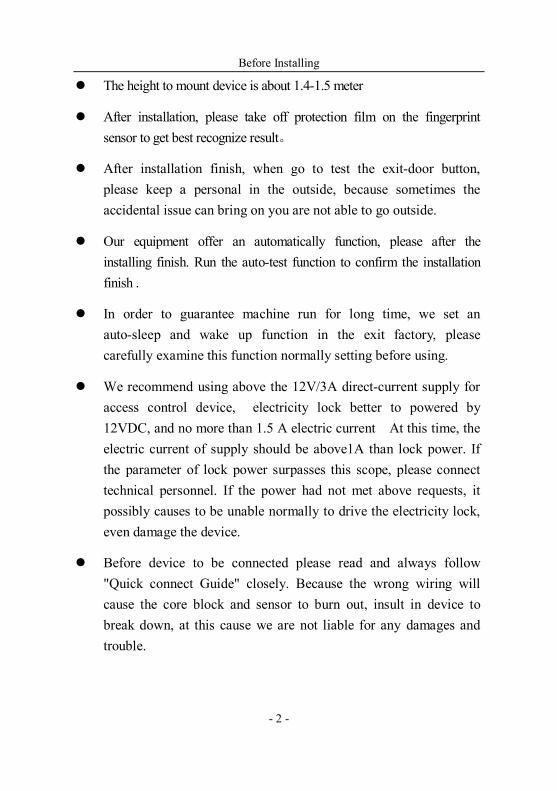
l The height to mount device is about 1.41.5 meter
l After installation, please take off protection film on the fingerprint sensor to get best recognize result。
l After installation finish, when go to test the exitdoor button, please keep a personal in the outside, because sometimes the accidental issue can bring on you are not able to go outside.
l Our equipment offer an automatically function, please after the installing finish. Run the autotest function to confirm the installation finish .
l In order to guarantee machine run for long time, we set an autosleep and wake up function in the exit factory, please carefully examine this function normally setting before using.
l We recommend using above the 12V/3A directcurrent supply for access control device, electricity lock better to powered by 12VDC, and no more than 1.5 A electric current At this time, the electric current of supply should be above1A than lock power. If the parameter of lock power surpasses this scope, please connect technical personnel. If the power had not met above requests, it possibly causes to be unable normally to drive the electricity lock, even damage the device.
l Before device to be connected please read and always follow "Quick connect Guide" closely. Because the wrong wiring will cause the core block and sensor to burn out, insult in device to break down, at this cause we are not liable for any damages and trouble.
F7 Installation InstructionV3.1.1
3
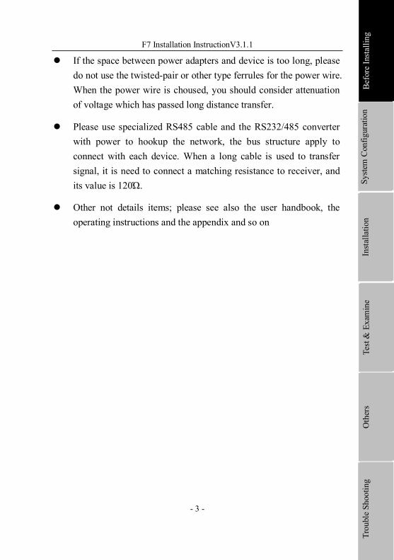
l If the space between power adapters and device is too long, please do not use the twistedpair or other type ferrules for the power wire. When the power wire is choused, you should consider attenuation of voltage which has passed long distance transfer.
l Please use specialized RS485 cable and the RS232/485 converter with power to hookup the network, the bus structure apply to connect with each device. When a long cable is used to transfer signal, it is need to connect a matching resistance to receiver, and its value is 120Ώ.
l Other not details items; please see also the user handbook, the operating instructions and the appendix and so on
Before Installing
System Configuration
Installation
Trouble Shooting
Test & Examine
Others
Before Installing
System Configuration
Installation
Trouble Shooting
Test & Examine
Others


F7 Installation InstructionV3.1.1
1
1.2 View of operation panel
Loudspeaker: give sound with operations。
LED light: on normally ready work status the green light glitters once per second; the green light is on for 3 seconds when a user is successful to verify. At the same time if the user fails to verify, the red light will be on for 3 seconds
LCD screen: It displays menu’s operation information.
Keypad: It is used to enter user ID or make menu operation.
Fingerprint Sensor: To enroll or verify fingerprint.
Reset:Be used to restart machine.
RJ45 port: Used for network connection with the computer.
Outlets:Used to connect the power, and other auxiliary equipments

F7 Installation InstructionV3.1.1
1
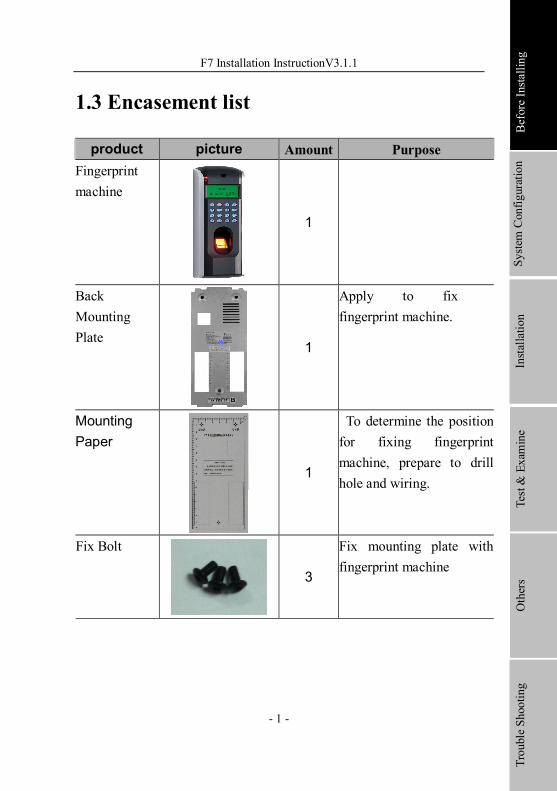
1.3 Encasement list
product picture Amount Purpose Fingerprint machine
1
Back Mounting Plate
1
Apply to fix fingerprint machine.
Mounting Paper
1
To determine the position for fixing fingerprint machine, prepare to drill hole and wiring.
Fix Bolt
3
Fix mounting plate with fingerprint machine
Before Installing
System Configuration
Installation
Trouble Shooting
Test & Examine
Others
Before Installing
2
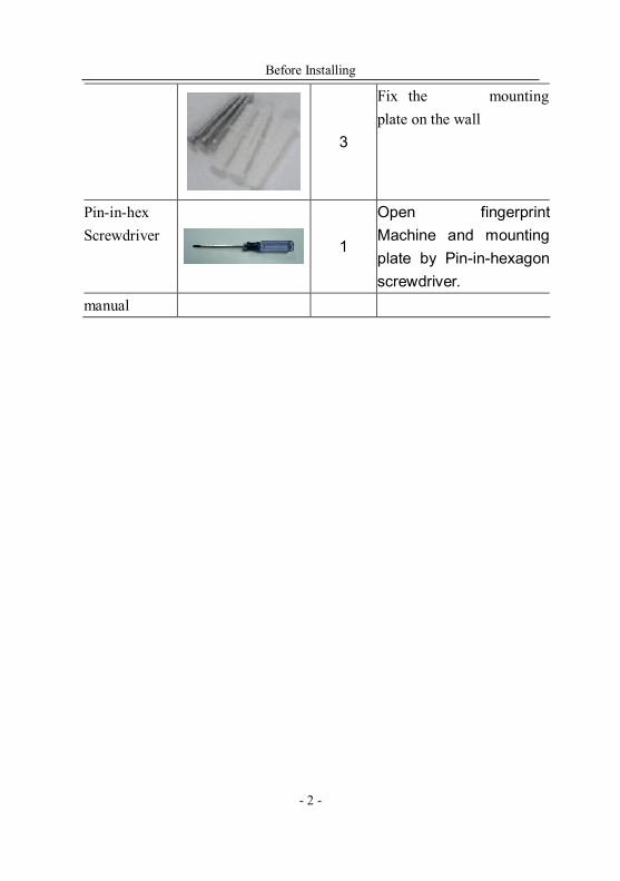
3
Fix the mounting plate on the wall
Pininhex Screwdriver
1
Open fingerprint Machine and mounting plate by Pininhexagon screwdriver.
manual
F7 Installation InstructionV3.1.1
3
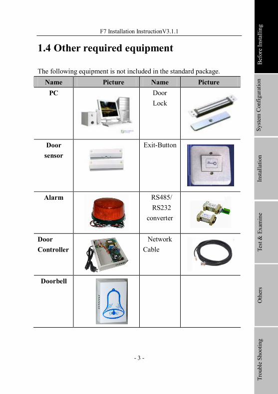
1.4 Other required equipment
The following equipment is not included in the standard package. Name Picture Name Picture PC Door
Lock
Door sensor
ExitButton
Alarm RS485/ RS232
converter
Door Controller
Network Cable
Doorbell
Before Installing
System Configuration
Installation
Trouble Shooting
Test & Examine
Others
System Configuration
4
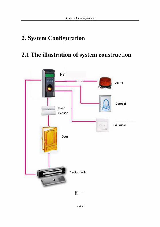
2. System Configuration
2.1 The illustration of system construction
图 一
F7 Installation InstructionV3.1.1
5
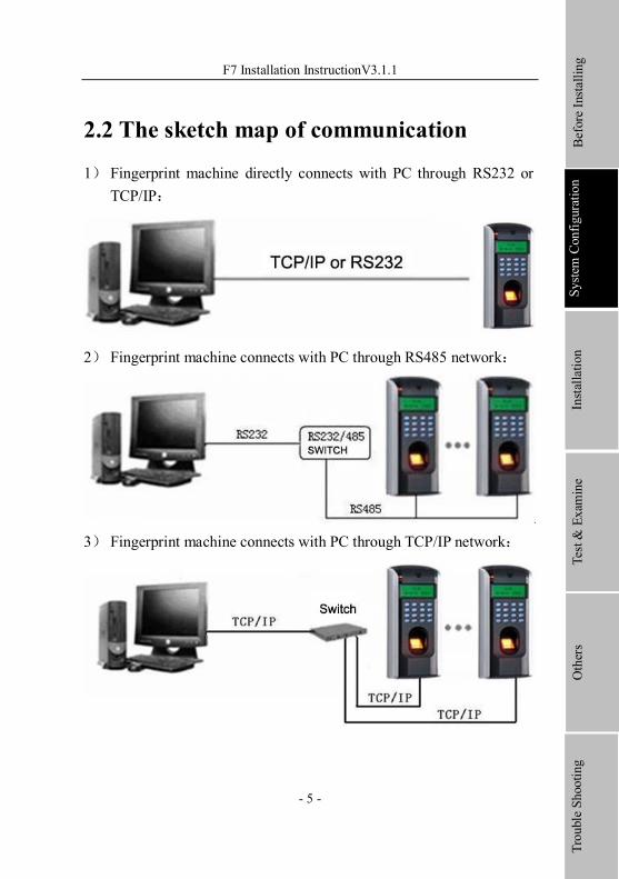
2.2 The sketch map of communication
1) Fingerprint machine directly connects with PC through RS232 or TCP/IP:
2) Fingerprint machine connects with PC through RS485 network:
3) Fingerprint machine connects with PC through TCP/IP network:
Before Installing
System Configuration
Installation
Trouble Shooting
Test & Examine
Others

Installation
6
3. Installation
3.1 Fix Mounting Plate
l determine the position of mounting plate on the wall. The fingerprint machine should be mounted on the external wall of the door approximately 1400mm from the ground to the unit bottom, take out a mounting template which along with this fingerprint machine, stick it on the determined position, follow illustration of the template to drill hole.
l Take out a fingerprint machine,dismantle the screw between machine body and mounting plate until it is out, see figure (1).
l Carefully take up the bottom of mounting plate, see figure (2), push it up, see figure (3), then take away the mounting plate.
l Make the hole of mounting plate meet the drilled hole on the wall, Use the screw to fix it on the wall, (for the details please see following figure a, b, c)
l After installation, please make sure the mounting plate is reliable, fasten, not loosed.
F7 Installation InstructionV3.1.1
7
3.2 Connect with peripheral equipment
Caution: Do not to connect peripheral equipment before the power of the device is cut down, otherwise it is possible to damage the device badly.
Please follow instruction to connect peripheral equipment
l Door sensor connection
l Door lock connection
l Alarm connection
l Exitbutton connection
l Doorbell connection
l RS232 connection
l RS485 connection
l Wiegand output connection
l Power connection Before Installing
System Configuration
Installation
Trouble Shooting
Test & Examine
Others
Installation
8
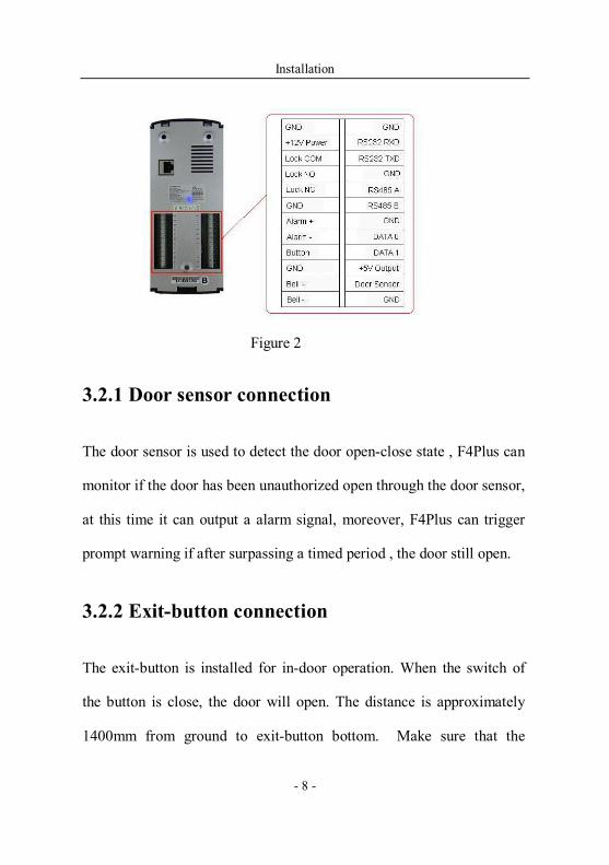
Figure 2
3.2.1 Door sensor connection
The door sensor is used to detect the door openclose state , F4Plus can
monitor if the door has been unauthorized open through the door sensor,
at this time it can output a alarm signal, moreover, F4Plus can trigger
prompt warning if after surpassing a timed period , the door still open.
3.2.2 Exitbutton connection
The exitbutton is installed for indoor operation. When the switch of
the button is close, the door will open. The distance is approximately
1400mm from ground to exitbutton bottom. Make sure that the
F7 Installation InstructionV3.1.1
9
exitbutton position is to align correct, upright and the connection is
accurate and reliable. (Unused exposed end of cable should be cut off,
and use insulating tape to wrap it.)Pay attention to electromagnetic
disturbance. (For example: The light switch, the computer and so on)
3.2.3 Alarm connection
F4Plus alarm output is a switch signal,it is able to connect with simple
alarm by serial circuit, it also apply to top grade alarm and monitor
system as a trigger signal( this machine alarm function only support 12
VDC Warner)
3.2.4 Doorbell connection
Doorbell terminal is connected directly with the doorbell button of
panel, so what you need to do is to connect the existing doorbell
switch to these two terminals.
Before Installing
System Configuration
Installation
Trouble Shooting
Test & Examine
Others

Installation
10
F7 Installation InstructionV3.1.1
11
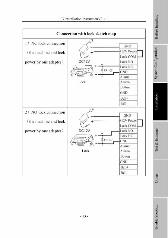
3.2.5 Door lock connection
The way of installing door lock depends on the type of lock and local condition. Internal resistor which comes from long distance transfer should be taken into consideration when selecting the cable of electric power. The door lock should be installed reliable and stable .Ensure the wiring is correct. For the strike lock and electromagnetic lock, you should pay attention to positive and negative terminal connection. The unused bare end of wire should be cut off and use insulating tape to wrap it. The delay time of strike lock is adjustable according to different conditions.
l When the Access Control System connected with Electric lock, to prevent the selfinductance EMF to affect the access control system, you need to parallel one FR107 diode (do not reverse the polarity) . Please use the equipped diode in the package.
Select electric lock :it is better to use electric drop bolt for the two –direction opening glass door (both open to inside or outside direction ) ,for the single opening wood door in company internal , we recommend to use magnetic lock, the magnetic lock also be called as electric magnetic lock,. The magnetic lock is more reliable than the electric drop bolt, but the electric drop bolt is much safer than the magnetic lock. In the small living community, it is better to use electric drop bolt and magnetic force lock. The electric control lock gives out higher noise; the electric control lock is commonly used to building communication. Now there is a soundless electric control lock which
Before Installing
System Configuration
Installation
Trouble Shooting
Test & Examine
Others

Installation
12
is able to be applied. Please pay attention, the lock is made of iron and easy rust, so you must beware of not exposing it to water or harsh condition, there are some other electric locks available, we don’t recommend you to use them.
Connect with electric lock:The NormalOpen lock is open when the power is off. The NormalClose lock is closed when power is off. The machine supports both of the two kinds of locks at the same time. The way of lock connection changes with the type of lock. For NO lock, the NO terminal will be used; for NC lock, the NC terminal will be used.
This access control machine is powered by DC12V and work current 400mA. If the lock work electric power is DC12V and the work current is less than 1000mA, the fingerprint machine and lock are able to be powered by one adapter together, please refer to table 1, 2.
In the following three cases, we recommend that fingerprint machine and lock are powered separately.
l The working voltage of the lock is DC12V, but the current difference of the fingerprint machine and the lock doesn’t exceed 1A.
l The lock voltage is not DC12V.
l The distance between lock and fingerprint machine is too far.
F7 Installation InstructionV3.1.1
13
Connection with lock sketch map
1)NC lock connection
(the machine and lock
power by one adapter)
2)NO lock connection
(the machine and lock
power by one adapter)
Before Installing
System Configuration
Installation
Trouble Shooting
Test & Examine
Others
Lock
Lock

Installation
14
3)NC lock connection
( The machine and
lock powered by
independent
adapters)
4)NO lock connection
( The machine and
lock powered by
independent
adapters)
Lock
Lock
Lock power
Lock power
F7 Installation InstructionV3.1.1
15
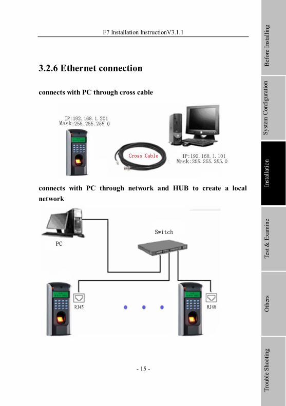
3.2.6 Ethernet connection
connects with PC through cross cable
connects with PC through network and HUB to create a local network
Before Installing
System Configuration
Installation
Trouble Shooting
Test & Examine
Others
Installation
16
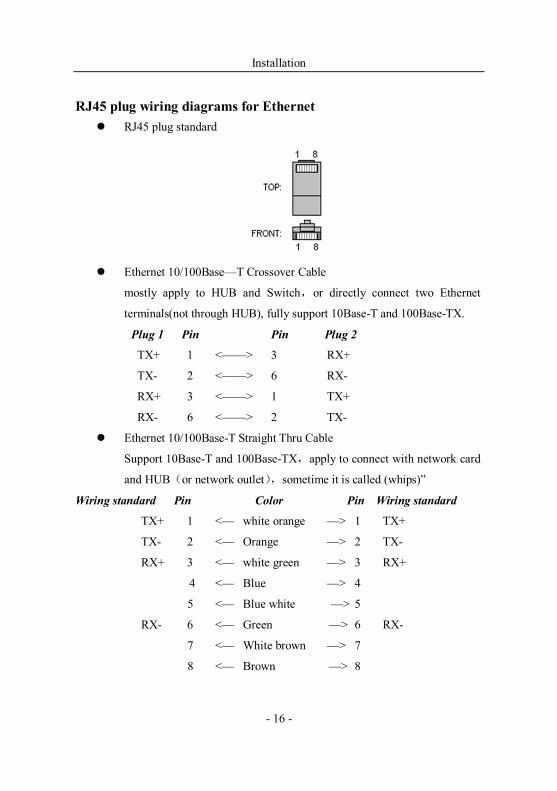
RJ45 plug wiring diagrams for Ethernet l RJ45 plug standard
l Ethernet 10/100Base—T Crossover Cable
mostly apply to HUB and Switch,or directly connect two Ethernet
terminals(not through HUB), fully support 10BaseT and 100BaseTX.
Plug 1 Pin Pin Plug 2
TX+ 1 <——> 3 RX+
TX 2 <——> 6 RX
RX+ 3 <——> 1 TX+
RX 6 <——> 2 TX
l Ethernet 10/100BaseT Straight Thru Cable
Support 10BaseT and 100BaseTX,apply to connect with network card
and HUB(or network outlet),sometime it is called (whips)”
Wiring standard Pin Color Pin Wiring standard
TX+ 1 <— white orange —> 1 TX+
TX 2 <— Orange —> 2 TX
RX+ 3 <— white green —> 3 RX+
4 <— Blue —> 4
5 <— Blue white —> 5
RX 6 <— Green —> 6 RX
7 <— White brown —> 7
8 <— Brown —> 8
F7 Installation InstructionV3.1.1
17
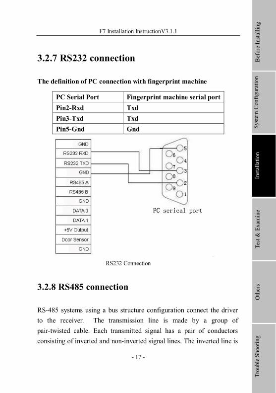
3.2.7 RS232 connection
The definition of PC connection with fingerprint machine
PC Serial Port Fingerprint machine serial port Pin2Rxd Txd Pin3Txd Txd Pin5Gnd Gnd
RS232 Connection
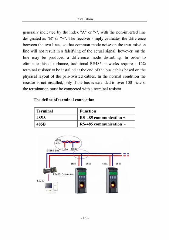
3.2.8 RS485 connection
RS485 systems using a bus structure configuration connect the driver to the receiver. The transmission line is made by a group of pairtwisted cable. Each transmitted signal has a pair of conductors consisting of inverted and noninverted signal lines. The inverted line is
Before Installing
System Configuration
Installation
Trouble Shooting
Test & Examine
Others
Installation
18
generally indicated by the index "A" or "", with the noninverted line designated as "B" or "+". The receiver simply evaluates the difference between the two lines, so that common mode noise on the transmission line will not result in a falsifying of the actual signal, however, on the line may be produced a difference mode disturbing. In order to eliminate this disturbance, traditional RS485 networks require a 12Ω terminal resistor to be installed at the end of the bus cables based on the physical layout of the pairtwisted cables. In the normal condition the resistor is not installed, only if the bus is extended to over 100 meters, the termination must be connected with a terminal resistor.
The define of terminal connection
Terminal Function 485A RS485 communication + 485B RS485 communication
F7 Installation InstructionV3.1.1
19
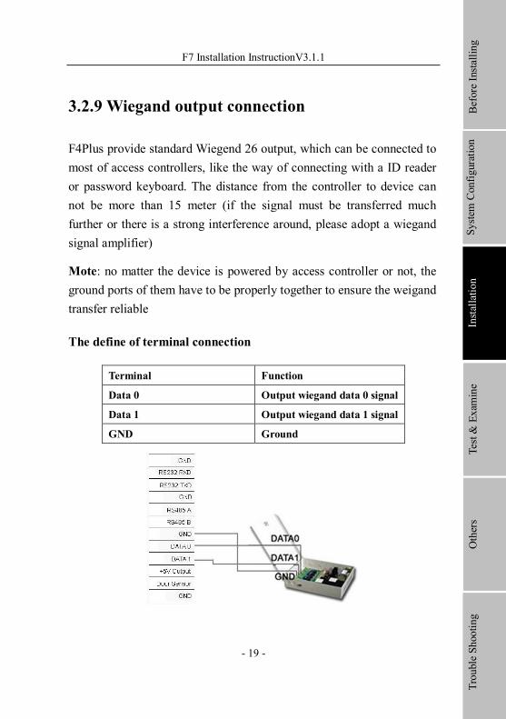
3.2.9 Wiegand output connection
F4Plus provide standard Wiegend 26 output, which can be connected to most of access controllers, like the way of connecting with a ID reader or password keyboard. The distance from the controller to device can not be more than 15 meter (if the signal must be transferred much further or there is a strong interference around, please adopt a wiegand signal amplifier)
Mote: no matter the device is powered by access controller or not, the ground ports of them have to be properly together to ensure the weigand transfer reliable
The define of terminal connection
Terminal Function
Data 0 Output wiegand data 0 signal
Data 1 Output wiegand data 1 signal
GND Ground
Before Installing
System Configuration
Installation
Trouble Shooting
Test & Examine
Others
Installation
20
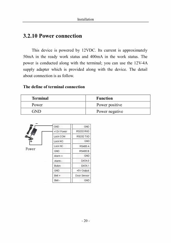
3.2.10 Power connection
This device is powered by 12VDC. Its current is approximately 50mA in the ready work status and 400mA in the work status. The power is conducted along with the terminal; you can use the 12V4A supply adapter which is provided along with the device. The detail about connection is as follow.
The define of terminal connection
Terminal Function Power Power positive GND Power negative
F7 Installation InstructionV3.1.1
21
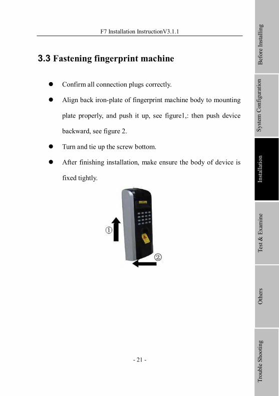
3.3 Fastening fingerprint machine
l Confirm all connection plugs correctly.
l Align back ironplate of fingerprint machine body to mounting
plate properly, and push it up, see figure1,: then push device
backward, see figure 2.
l Turn and tie up the screw bottom.
l After finishing installation, make ensure the body of device is
fixed tightly.
Before Installing
System Configuration
Installation
Trouble Shooting
Test & Examine
Others

Test & Examine
22
4. Test and examine after installation
After all system installation finished, make a test and examine prior to power on , inspect whether the lock driver is OK or not,, for more details, please see “User Guide” and “Software Manual”
l The green LED begin to glitter after power up.
l Enter menu〉Option〉 Autotest.
l Enter menu〉User manage〉User Enroll〉Fingerprint Enroll, Enroll a fingerprint, and use the fingerprint to test access control system and door lock..
l If there is no any problem. Please delete this enrolled fingerprint.5.
F7 Installation InstructionV3.1.1
23
5. Others
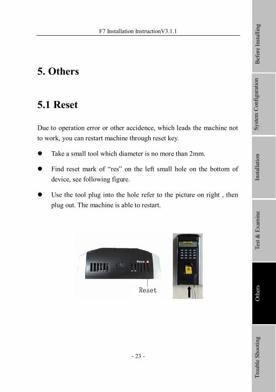
5.1 Reset
Due to operation error or other accidence, which leads the machine not to work, you can restart machine through reset key.
l Take a small tool which diameter is no more than 2mm.
l Find reset mark of “res” on the left small hole on the bottom of device, see following figure.
l Use the tool plug into the hole refer to the picture on right , then plug out. The machine is able to restart.
Before Installing
System Configuration
Installation
Trouble Shooting
Test & Examine
Others
Others
24
5.2Antidismantle button
Antidismantle button is on middle of device, whose function is realized
by backcover pressing the antidismantle button. When the device is
being dismantled, it will send a alarm signal through the terminal, more
detail please see this handbook 4.23.
5.3 Electrical Power Output This equipment is able to provide 5VDC/300mA power output, this
output ability power on periphery equipment.
F7 Installation InstructionV3.1.1
25
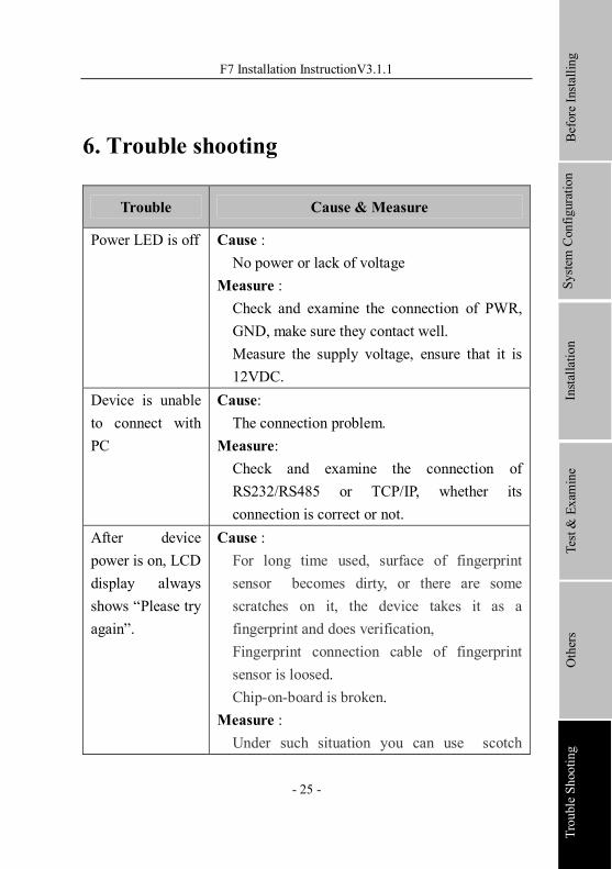
6. Trouble shooting
Trouble Cause & Measure
Power LED is off Cause : No power or lack of voltage
Measure : Check and examine the connection of PWR, GND, make sure they contact well. Measure the supply voltage, ensure that it is 12VDC.
Device is unable to connect with PC
Cause: The connection problem.
Measure: Check and examine the connection of RS232/RS485 or TCP/IP, whether its connection is correct or not.
After device power is on, LCD display always shows “Please try again”.
Cause : For long time used, surface of fingerprint sensor becomes dirty, or there are some scratches on it, the device takes it as a fingerprint and does verification, Fingerprint connection cable of fingerprint sensor is loosed. Chiponboard is broken.
Measure : Under such situation you can use scotch
Before Installing
System Configuration
Installation
TroubleShooting
Test & Examine
Others
Trouble shooting
26
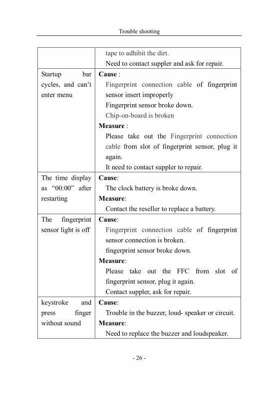
tape to adhibit the dirt. Need to contact suppler and ask for repair.
Startup bar cycles, and can’t enter menu
Cause : Fingerprint connection cable of fingerprint sensor insert improperly Fingerprint sensor broke down. Chiponboard is broken
Measure : Please take out the Fingerprint connection cable from slot of fingerprint sensor, plug it again. It need to contact suppler to repair.
The time display as “00:00” after restarting
Cause: The clock battery is broke down.
Measure: Contact the reseller to replace a battery.
The fingerprint sensor light is off
Cause: Fingerprint connection cable of fingerprint sensor connection is broken. fingerprint sensor broke down.
Measure: Please take out the FFC from slot of fingerprint sensor, plug it again. Contact suppler, ask for repair.
keystroke and press finger without sound
Cause: Trouble in the buzzer, loud speaker or circuit.
Measure: Need to replace the buzzer and loudspeaker.
F7 Installation InstructionV3.1.1
27
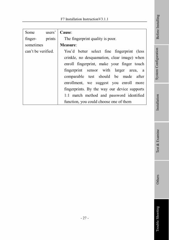
Some users’ finger prints sometimes can’t be verified.
Cause: The fingerprint quality is poor.
Measure: You’d better select fine fingerprint (less crinkle, no desquamation, clear image) when enroll fingerprint, make your finger touch fingerprint sensor with larger area, a comparable test should be made after enrollment, we suggest you enroll more fingerprints. By the way our device supports 1:1 match method and password identified function, you could choose one of them
Before Installing
System Configuration
Installation
Trouble Shooting
Test & Examine
Others