F/6 13/13 mmEmEmI&!EEEEEE - dtic.mil · unclassified security classification of this page (3hou de...
59
AD-AION 695 HORNER AND SHIFRIN INC ST LOUIS MO F/6 13/13 NATIONAL DAM SAFETY PROGRAM. GWENMIL LAKE DAM (MO 312101' UPPER-ETC(U) APR 81 R E SAUTHOFF, A A BECKER DACW4381-C0002 UNCLASSIFIED NL mmEmEmI&!EEEEEE
Transcript of F/6 13/13 mmEmEmI&!EEEEEE - dtic.mil · unclassified security classification of this page (3hou de...

AD-AION 695 HORNER AND SHIFRIN INC ST LOUIS MO F/6 13/13NATIONAL DAM SAFETY PROGRAM. GWENMIL LAKE DAM (MO 312101' UPPER-ETC(U)APR 81 R E SAUTHOFF, A A BECKER DACW4381-C0002
UNCLASSIFIED NL
mmEmEmI&!EEEEEE

3 UPPER MISSISSIPPI - KASKASKIA - ST. LOUIS BASIN
a.l GWENMIL LAKE DAM, 0JEFFERSON COUNTY, MISSOURI
MO 31210
SPHASE 1 INSPECTION REPORT.I NATIONAL DAM SAFETY PROGRAM,
( United States Army oaellIlCorps of Engineers
..Sen ing the Army
... rSing the Nation C c 1*
St. Louis District.( ,,, 4
' PREPARED BY: U.S. ARMY ENGINEER DISTRICT, ST. LOUIS
FOR: STATE OF MISSOURI 81 9 28 073
APRIL 1981 --
UNCLASSIFIEDSECURITY CLASSIFICATION OF THIS PAGE (3hou De Entered)
READ INSTRUCTIONSREPORT DOCUMENTATION PAGE BEFORE COMPLETING FORMI. REPORT NUMBER 2. GOVT ACCESSION NO 3. RECIPIENT'S CATALOG NUMBER
4. TITLE (aod Subtitle) -T "yPE OF REA.z & BERIOD COVEREO
Phase I Dam Inspection ReportNational Dam Safety Program . Final FewtOwenmil Lake Dam (MO 31210) --..- Pae"weAqM*OI OePORT NUMBER
Jefferson County, Missouri
7. AUTHOR(a) 8. CONTRACT OR GRANT NUMBER(s)Horner & Shifrin, Inc.
DACW43-81-C-0002,S. PERFORMING ORGANIZATION NAME AND ADDRESS 10. PROURAM 'LWR.W MOJECT, TASKU.S. Army Engineer District, St. Louis AREA & WORK UNIT NUMBERS
Dam Inventory and Inspection Section, LMSED-PD210 Tucker Blvd., North, St. Louis, Mo. 63101
11. CONTROLLING OFFICE NAME AND ADDRESS . 12. 'REOl-W" -U.S. Army Engineer District, St. Louis /! April j. 81 /Dam Inventory and Inspection Section, LMSED-PD-- IS. NUMUmrCW'O7PGES
210 Tucker Blvd., North, St. Louis, Mo. 63101 Approximately 4514. MONITORING AGENCY NAME & ADDRESS(if different from Controllinn Office) 15. SECURITY CLASS. (of this report)
.. .UNCLASSIFIED21 .1S&. DECLASSI FICATION/ DOWNGRADING
SCHEDULE
16. DISTRIBUTION STATEMENT (of this Report)
AppPoeddnf4r.-Pe1ease; distribution url mited.,'/- i ' -
is.
National Dam Safety Program. wenmilLake Dam (MO 31210)9 Upper
IS. SUPPLEMENTARY NOTES Mississippi - Kaskaskia - St. Louis,Basinh'-Jefferson County, Missouri.Phase In Inspection Report.
11. KEY WORDS (Continue on r ver ,e aide If neceeary and Identify by block number)
Dam Safety, Lake, Dam Inspection, Private Dams
16 A TTRACT (Cmtlae e ,emhm N neremy wAd IdeWl1Y by block neubet)This report was prepared under the National Program of Inspection ofNon-Federal Dams. This report assesses the general condition of the dam withrespect to safety, based on available data and on visual inspection, todetermine if the dam poses hazards to human life or property.
DD OM 1473 Mo10 OF I NOV65 IS OBSOLETE UCAIE0072 UNCLASSIFIED "
/' ) / SECURITY CLASSIFICATION OF THIS PAGE (When Date Enrered)

SECURITY CLASSIFICATION OF THIS PAGE4Wb DO*e 8atut.
SECURITY CLASSIFICATION OF THIS PAGF~tneu Dot* Ent~ed)

UPPER MISSISSIPPI - KASKASKIA - ST. LOUIS BASIN
GWENMIL LAKE DAM
JEFFERSON COUNTY, MISSOURI
MO 31210
PHASE 1 INSPECTION REPORTNATIONAL DAM SAFETY PROGRAM
[ United States ArmyCorps of Engineers.,. Sming the Army... Senin g the Notwtn
St. Louis District
PREPARED BY: U.S. ARMY ENGINEER DISTRICT, ST. LOUIS
*! FOR: STATE OF MISSOURI
APRIL 1981
.t.

7. DEPARTMENT OF THE ARMYST. LOUIS DISTRICT. CORPS OF ENGINEERS
210 TUCKER BOULEVARD, NOrkTHMe I Io ST. LOUIS. MISSOURI 63101
LMSED-P
SUBJECT: Gwenmil Lake Dam, MO 31210
This report presents the results of field inspection and evaluation of the
Gwenmil Lake Dam, MO 31210. It was prepared under the National Program of
Inspection of Non-Federal Dams.
SUBMITTED BY: SIGNED 19 J;1, 1981Chief, Engineering Division Date
BY: SIGNED 22 JUN 1981Colonel, CE, District Engineer Date
Accession o
NTIS grA&I-DTICTL [
,uaniuounc e-d
Just fication_
By--__Distri,,: <,
Avail11,1 i ,,.. '.i',Avli', ;i.'.
Di-t . 1
I. k

I'
GWENMIL LAKE DAM
MISSOURI INVENTORY NO. 31210
JEFFERSON COUNTY, MISSOURI
PHASE I INSPECTION REPORTNATIONAL DAM SAFETY PROGRAM
PREPARED BY:
HORNER & SHIFRIN, INC.5200 OAKLAND AVENUE
ST. LOUIS, MISSOURI 63110
FOR:
U. S. ARMY ENGINEER DISTRICT, ST. LOUISCORPS OF ENGINEERS
APRIL 1981
HS-8088

PHA.SE I REPORT
NA~TIONA~L DA~M SAFETY PROGRA~M
Name of Dam: Gwennil Lake Dam
State Located: Missouri
County Located: Jeffer :cn
Stream: Tributary of Isuin Creek
Date of Inspection: 7 November 1980
The Gwenmil Lake Dam, which according to the St. Louis District, Corps of
Engineers, is of significant hazard potential, was visually inspected by
engineering personnel of Homner b Shifrin, Inc., Consul1ting Engineers, St.
Louis, Missouri. The purpose of this inspection was to assess the general
condition of the dam with respect to safety and, based upon this inspection
and available data, determine if the dam poses an inordinate danger to human
life or property. Evaluation of this dam was performed in accordance with the
"Phase I" investigation procedures prescribed in "Recommended Guidelines for
Safety Inspection of Dams", dated May 1975.
The following summarizes the findings of the visual inspection and the
results of certain hydrologic/hydraulic investigations performed under the
direction of the inspection team. Based on the visual inspection, the present
general condition of the Jam is considered to be somewhat less than
satisfactory. Several items were noticed during the inspection which are
considered to have an adverse effect on the overall safety and future
operation of the dam. These items include trees and areas of dense brush on
the downstream face of the embankment, an excessively steep (as much as 1.Ov
on 1.5h) downstream slope, erosion of the grass covered upstream face of the
Alii

dam, and a dense growth of cattails within the reservoir just upstream of the
spillway.
According to the criteria set forth in th recommended guidelines, the
magnitude of the spillway design flu-1 for the Gwenmil Lake Dam, which,
according to Table 1 of the guidelines, is clissified as small in size; is
specified, according to Table 3 of the quideliines for a dam of significant
hazard potential and small size, to be a minimum of the 100-year frequency
flood and can be, depending upon the degree of risk involved, as much as
one-half the Probable Maximum Flood (PMF). The 100-year frequency flood is
the flood magnitude expected to be exceeded, on the average, once in 100
years. It may also be expressed as an exceedence frequency with a 1 percent
chance of being exceeded in any given year. The Probable Maximum Flood (PMF)
is the flood that may be expected from the most severe combination of critical
meteorologic and hydrologic conditions that are reasonably possible in the
region. Considering the fact that a relatively small volume of water is
impounded by the dam, that the flood plain downstream of the dam is fairly
broad, that there are but three dwellings (two of which are well above the
streambed) and a non-high hazard potential dam within the flood damage zone,
it is recommended that the spillway for this dam be designed for the 100-year
frequency flood.
Results of a hydrologic/hydraulic analysis indicated that the spillway is
adequate to pass lake outflow resulting from the 1 percent chance (100-year
frequency) flood and, for all practical purposes, the lake outflow resulting
from a storm of one-half PMF magnitude without overtopping the dam. According
to the St. Louis District, Corps of Engineers, the lenqth of the downstream
damage zone, should failure of the dam occur, is estimated to be two miles.
Accordingly, within the potential damage zone are three dwellings, a dam (MO
30431), and two farm buildings. Dam No. 30431, according to the Corps of
Engineers, also has a significant (less than high) hazard potential
classification. No determination was made whether or not failure of Dam No.
30431 would occur during any of the flood events or conditions of overtopping
investigated herein.
ii

A review of available data did not disclose that seepage or stability
analyses of the dam were performed. This is considered a deficiency and
should be rectified.
It is recommended that the Owner take the necessary action in the near
future to correct or control the deficiencies and safety defects reported
herein.
~l
RalpK E. SauthbffP. E. Missouri E-19090
Albert B. Becker, Jr.P. E. Missouri E-9168
iii

-J
Li
C-
* .. , Zr.. V '-I

PhASE I INSPECTION REPORT
NATIONAL DAM SAFETY PROGRAM 1
GWENMIL LAKE DAM - MO 31210
TABLE OF CONTENTS
Paragriph No. Title Page No.
SECTION 1 - PROJECT INFORMATION
1.1 General 1-1
1.2 Description of Project 1-1
1.3 Pertinent Data 1-4
SECTION 2 - ENGINEERING DATA
2.1 Design 2-1
2.2 Construction 2-i
2.3 Operation 2-1
2.4 Evaluation 2-1
SECTION 3 - VISUAL INSPECTION
3.1 Findings 3-1
3.2 Evaluation 3-3
SECTION 4 - OPERATIONAL PROCEDURES
4.1 Procedures 4-1
4.2 Maintenance of Dam 4-1
4.3 Maintenance of Outlet Operating
Facilities 4-i
4.4 Description of Any Warning
System in Effect 4-1
4.5 Evaluation 4-1
TC-1
.. :-

Paragraph No. itle Paqe No.
SECTION 5 - HYLP\UL /! )RQJ I
5.1 EvaluaLion of -tLt'NJ 5-1
SECTION 6 - STRUCTURAL STA5ILITY
6.1 Evaluation of Structural StabIlit 6-I
SECTION 7 - ASSESSMENT/REMEDIAL MEASURES
7.1 Dam Assessment 7-1
7.2 Remedial Measure- 7-2
LIST OF PLATES
Plate No. Title
1 Regional Vicinity Map
2 Lake Watershed Map
3 Dam Plan and Profile
4 Dam Cross-Section
5 Spillway Profile & Cross-Section
APPENDIX A - INSPECTION PHOTOGRA'HS
Page No. Title
A-I thru A-3 Inspection Photographs
T C-2

APPENDIX B - HYDRCLOGIC AND HYDRAULIC ANALYSES
Page No. Title
B-1 and B-2 Hydrologic & Hydraulic Computations
B-3 thru B-5 Computer Input Data
B-6 thru B-10 Computer Output Data
3-10 Lake Surface Area, SLorage Volume and Elevation;
Summary of Dam Safety Analysis
B-il Table of Spillway Rating Curve Values
TC-3

PHASE I I !id 1ECTI nrJ kEPOi T
NATIONAL DAM SAFETY PROGRAM
GWENMIL LAKE DAM - MO 31210
SECTION 1 - PROJECT INFORMATION
1.1 GENERAL
a. Authority. The National Dam Inspection Act, Public Law 92-367, dated
8 August 1972, authorized the Secretary of the Army, through the Corps of
Engineers, to initiate a program of safety inspection of dams throughout the
United States. Pursuant to the above, the St. Louis District, Corps of
Engineers, directed that a safety inspection of the Gwenmil Lake Dam be made.
b. Purpose of Inspection. The purpose of this visual inspection was to
make an assessment of the general condition of the dam with respect to safety
and, based upon available data and this inspection, determine if the dam poses
an inordinate danger to human life or property.
c. Evaluation Criteria. This evaluation was performed in accordance
with the "Phase I" investigation procedures as prescribed in "Recommended
Guidelines for Safety Inspuction of Dams", Appendix D to "Report to the Chief
of Engineers on the National Program of Inspection of Non-Federal Darns", dated
May 1975.
1.2 DESCRIPTION OF PROJECT
a. Description of Dam and Appurtenances. The Gwenmil Lake Dam is an
earthfill type embankment rising approximately 29 feet above the natural
streambed at the downstream toe of the barrier. The embankment has an
upstream slope (above the waterline) of approximately lv on 3.Oh, a crest
width of about 17 feet, and a downstream slope on the order of lv on 2.Oh,
although it becomes somewhat less steep, lv on 3.1h, near the base and, at the
location of the original stream channel at an elevation approximately 22 feet
below the dam crest, the downstream slope steepens to about lv on l.5h. The
I-I

o ,-ie c,,,7 ip r xin*- l I ~, ~ t :f1
P show~n on -)~t xit a'd r. CC2:t': §2 .
,2roxirnate'y 39.;) cres. Acccrinr to Mrs." c.
ownler of t,'i -1,m, ipe atout 3 inch-es i> HI2
.thnstreaT enol wa~s -roviOec to dewater th 3.? T~r- -iee CZCnot o,
..ocat& -,7 t~e tiN?,, of i.2srect ion. 7 j~r SiA.h~:Ji
T , '- he nn eo~ c t i n, Is 3.cc: t.
.v ..C eS7
C r~:~ -
A. .c~t~f.Tnt? dar, Is 10123tO -r
N-1rnin thE: -.,venmi.i aud~SC,3r~~ni~
.Z~iiio~ loCate, just So Uto iorel. T1 ~ ~f-)P nt 2rse:: Icrn (,f Hilisb~oro RCaO 3nd LLn- . ty7
miles t ast cf Cedar Hlili, Missouri, as '3won *he .- r ' ciflity 43
')late I. The damn is located In the sottheast 'noana r jm7
?wf~llA J, ort, anae 4 East, within J~rn O~
1-1; ~imsification. The size cl-3ssif'xitlon I. .v thi, h.,kicnt :f
the z-~ .o~ cap23C~tyIs ct~~~' r.

RecommendeO Guidelines for Saf!-ty Inrsc~otiron hfam-is). 0 -a'L' S,!e dl~il iV
classified, according to the auidlir~s, -3s !iavin.: a leon ss tha:n 43D feet,
b)ut greater than or equal to 25 feet and/ocr: storace car~c, 2y es:s than ,D?
acre-feet, buit greater than or oqual to 50 acre-fe-et.
d. HaIZarJ ClassiFication. The Ivvenmil -ake Da-ri, oor tC thiE St.
Louis Pl.istrict , Ccros of Enoineers, n as asoficant1 ' _7-3ro C_ e'l 1meanino tha,,t If the cam shc-ld fail, tr:ere _, e .'css ol life, -a'raw- to3
isolate,- home.s, secondary ni giways or 7inor railroads, or -iise it:uto
of udoe or service of relativel-v P.ortant ou~ tlre. T-ie :ma
ilool dez,-,ce zone, should failure ofto darn occir, as otr:ec 0 t
Loui Ds t rict, extends two miles do.A--stem o -f the 3 oo. %ihnt-e I ssc
flIood_ camarn e zone are' three iweilinos, 3 -Kci Ck1I 2:to~
:Dui 1 Jing.-. D-am No. 300i31, accordino t '_ Grs ~~c>9; ha!; a
cn~fn t - less 'than hicKh nazard otnr cizS ifiC_-r. Th-ose eta
lv inc 6_:tnin --)e downstream zarn"aace Lzone eo;e ' 'o_: .,mes
St.~~~ ZoX itit, were Verlf eo ;
-vvner-shi:,. The ! .e on:_- cdar- are o~' ~ * Ae~riii
* an~ssoiaionof hcrnir. owners wlHO re.:ioe sit-i :-
jr f:, f:ajr,. Toe -,am drn ods 3~'- z rr-w-
C. -ei n osroion Hist3ri. rcorxr 1. AOc<, Mr
CooV ano her *ushnand, G'Ler H. Cocak AeeaCu , Tcr :Wtmerb Cf the
dam, the dam Nas oonstruJcttd dorinC the foil oF t5 ei r 'tri.3I
and Excavatirn ConiPany of Cedar Hill, Visouri. Yr *e: oresident
of the construction company at the time the dam was buji ' :zrte,_ that the
cam had been "laid out" b)y others (unknown party) prio r -3 't- r o'pqinning
01wok, jut thatl thCv, the Ricken Oompany, faid complIetet' e --T 3- norinailv
planned. No enaineering data relit!i-e to the de-zirn or )rs f tne
construction of the dam are known to exist.

h. Normal Operational Procedure. Th, lake level is unregulated. Lake
outflow is governed by the capacity of an excavated earth type spillway.
1.3 PERTINENT DATA
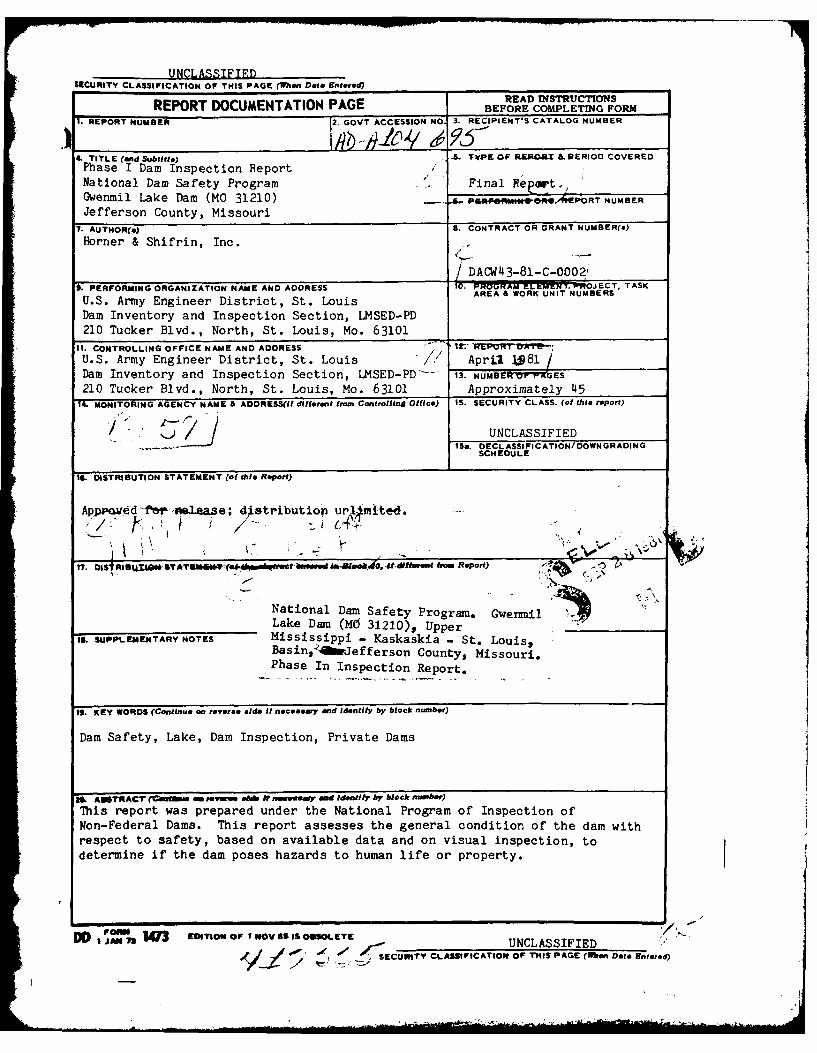
a. Drainage Area. The area tributary to the lake is a residential type
subdivision development consisting of approximately 25 percent impervious
area. The watershed above the dam amounts to approximately 15 acres. The
watershed area is outlined on Plate 2.
b. Discharge at Damsite.
(1) Estimated known maximum flood at damsite ... 31 cfs* (W.S.Elev. 635.6)
(2) Spillway capacity ... 94 cfs (W.S.Elev. 636.2)
c. Elevation (Ft. above MSL). Unless otherwise indicated, the following
elevations were determined by survey and are based on topographic dcta shown
on the 1954 Belew Creek, Misrouri, Quadrangle Map, 7.5 Minute Series
(photorevised 1968 and 1974).
(1) Observed pool ... 632.8
(2) Normal pool ... 635.0
(3) Spillway crest ... 635.0
(4) Maximum experienced pool ... 635.6*
(5) Top of dam ... 636.2 (Min.)
(6) Streambed at centerline of dam ... 610+ (Est.)
(7) Maximum tailwater ... Unknown
(8) Observed tailwater ... None
d. Reservoir.
(1) Length at normal pool (Elev. 635.0) ... 500 ft.
(2) Length at maximum pool (Elev. 636.2) ... 525 ft.
*Based on an estimate of depth of flow at spillway as observed by Mr. Larry
Cook, a resident of Gwenmil Subdivision.
1-4

e. Storage.
(1) Normal pool ... 23 ac. ft.
(2) Top of dam ... 27 ac. ft.
f. Reservoir Surface Area.
(1) Normal pool ... 3.0 acres
(2) Top of dam ,.. 3.4 acre
g. Dam. The height of the dam is defined to be the overall vertical
distance from the lowest point of foundation surface at the downstream toe of
the barrier, to the top of the dam.
(1) Type ... Earthfill, homogeneous*
(2) Length ... 341 ft.
(3) Height ... 29 ft.
(4) Top width ... 17 ft.
(5) Side slopes
a. Upstream ... Iv on 3.Oh (above waterline)
b. Downstream ... lv on 3.1h to lv on l.5h (at original stream)
(6) Cutoff ... Core trench*
(7) Slope protection
a. Upstream ... Grass
b. Downstream ... Grass
h. Spillway.
(i) Type ... Uncontrolled, earth channel with concrete retaining wall
at upstream end
(2) Location ... Left abutment
(3) Crest ... Elevation 635.0 (top of wall)
(4) Approach channel ... Lake
(5) Outlet channel ... Natural drainage swale
*Per Mr. Walter Ficken, dam builder.
1-5
LII .. . .. . ... . .. .I I i m . .. - , ,

II.
i. Emergency Spillway ... None
j. Lake Drawdown Facility. The former uwner, Mrs. Mildred L. Cook,
reported that a 3-inch diameter pipe, capped at the downstream end, was
installed through the dam for the purporse of draining the lake. However, the
drain line could not be located during the inspection.
1-6

SECTION 2 - ENCINFLRING DATA
2.1 DESIGN
Data relating to the design of the dam were ui''i ilable.
2.2 CONSTRUCTION
As previously stated, the dam was constructed in 1957 by the Ficken
Material and Excavating Company. According to Walter H. Ficken, president of
the company, a core trench for seepage cutoff was excavated to solid rock
along the axis of the dam. Mr. Ficken indicated that the core trench was
approximately lO-tn-12 feet wide, and that the clay material for backfilling
the trench and constructing the embankment was selected from areas to be
occupied by the lake. No records of the construction of the dam were
available.
2.3 OPERATION
The lake level is uncontrolled and governed by the elevation of the top of
a concrete retaining wall located at the upstream end of an excavated earth
type spillway. No indication was found that thc dam has been overtopped. The
former owner, Mrs. Mildred Cook, who has lived within the Gwenmil Subdivision
since before the dam was constructed, reported that the dam has never been
overtopped. According to Mr. Larry Cook, a resident of the Gwenmil
Subdivision, the highest lake level experienced to date occurred about 4 or 5
years ago when a storn produced a depth of flow at the spillway wall estimated
to be about 7 inches.
2.4 EVALUATION
a. Availability. Engineering data for assessing the design of the dam
and spillway were unavailable.
b. Adequacy. No data available. Seepage and stability analyses
comparable to the requirements of the "Recommended Guidelines for Safety
2-1

Inspection of Dams" were not available, which is considered a deficiency.
These seepage and stability analyses should he~ performed ror appropriate
loading conditions (including earthquake loads) and macic a matter of record.
2-2

SECTION 3 - VISUAL INSPECTION
3.1 FINDINGS
a. General. A visual inspection of the Gwenmil Lake Dam was made by
Homer & Shifrin engineering personnel, R. E. Sauthoff, Civil Engineer,
H. B. Locb..tt, Hydrologist, and A. B. Becket, Jr., Civil and Soils Engineer,
on 7 November 1980. A representative oi the Owner wwu not present during the
inspection. An examination of the dam area was also made by an engineering
geologist, Jerry D. Higgins, Ph.D., a consultant retained by Horner & Shifrin
for the purpose of assessing the site geoloqy. Also examined at the time of
the inspection were the areas and features below the dam within the potential
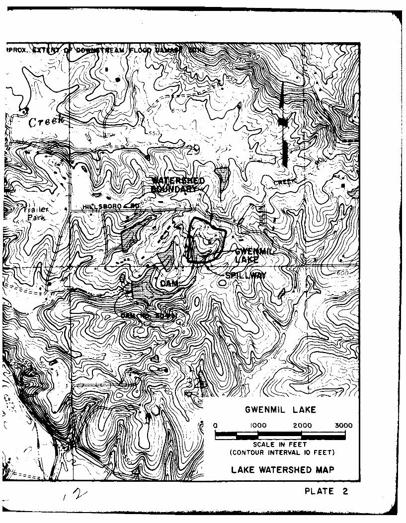
flood damage zone. Photographs of the dam taken at the time of the inspection
are included on pages A-i throutgh A-3 of Appendix A. The locations of the
photographs taken during the inspection are indicated on Plate 3.
b. Site Geology. Gwenmil Dam is located on an unnamed tributary to Isum
Creek, which flows into the Big River approximately two miles to the west.
The topography in this area is moderately to gently rolling, and there is
about 70 feet of relief between the reservoir bottom and the surrounding
drainage divide. The topography becomes more rugged toward the Big River
Valley, so that regionally there is about 350 feet of relief. The area is
included within the northeastern part of the Ozark Plateaus Poysiographic
Province, and regionally the bedrock structure dips northeastward into the
Illinois Basin.
There are no rock outcrops in the immediate vicinity of the site;
however, the reservoir and surrounding uplands are underlain by the Ordovician-
age Jefferson City formation. This is a linht brown to gray, finely
crystalline, argillaceous dolomite. It is generally thin- to medium-bedded
and contains both nodular and bedded chert, as well as some thin sandstone
layers. Solution enlargement of joints and bedding planes is common, and the
contact between bedrock and the overlying soils is generally very irregular as
a result of the solution weathering. These solution features are commonly the
cause of reservoir leakage when the soil cover is thin.
3-1

The soils derived from the Jefferson City formation are reddish-brown to
buff-colored, moderately plastic clays, usually mixed with silt on the upl nd
areas (ML-CL, Lnified Soil Classification System). in the vicin'ty of the
reservoir, the soils include a noticeable sand component that has probably
been derived from the original overlying St. Peter Sandstone formation, that
now has been totally removed from the area by erosion. Weathering of thin
sandstone lenses within the formation may have added sand to the cla, soils.
No geologic conditions were noted at the site that would be considered to
be detrimental to the performance of the reservoir or embankment stability.
c. Dam. The visible portions of the upstream and downstream faces of
the dam (see Photos 1, 2 and 3), as well as the dam crest, were inspected and,
except for some erosion of the upstream face at the waterline, appeared to be
in sound condition. No undue settlement of the crest, sliding or sloughing of
the embankment slopes, or misalignment of the dam was noted. For the most
part, the downstream face of the dam was covered with dense brush and trees up
to 4 inches in diameter. Except for grass about 12 inches high, the upstream
face of the dam was unprotected, i.e., no riprap, and erosion (see Photo 9),
apparently by wave action or changes in the lake level, had created a near
vertical bank up to 12 inches high at the normal waterline. Due to the
presence of several dense stands of cattails at the waterline, the upstream
face of the dam could not be thoroughly examined, and although no animal
burrows were seen, it is possible that some exist. The crest of the dam was
well covered with grass, a fescue, about 3 inches high. Examination of a 5oil
sample obtained from the downstream face near the center of the dam indicated
the surficial material to be a light brown, silty lean clay (CL) of
low-to-medium plasticity.
The grass-covered earth spillway (see Photos 5 and 6) as well as the
visible portions of both the upstream (see Photo 4) and downstream (see Photo
7) retaining walls appeared to be in satisfactory condition. A small gully,
about 6 inches deep and up to 2 feet in width located near the center of the
spillway, that served as a pilot channel extended the length of the crest
section. At the downstream end of the crest section, the gully within the
spillway channel was extensively eroded and followed a course that carried it
3-2
Ii'

past the left end of the downstream retaining wall (see Photo 7) and beyond,
what appeared to be, the intended spillway outlet channel where it joined a
natural drainage swale at a point about 25 feet south, or downstream, of the
intended channel. A large pile of tree branches that appeared to have been
purposely placed covered about two-thirds of the retaining wall. Both the
intended outlet channel (see Photo 8) and the natural swale were somewhat
overgrown with brush and small trees. A minor quantity of standing water, the
origin of which could not be determined, was observed aL the junction of the
spillway outlet channel and the original stream channel. However, no
indication of lake seepage was observed adjacent to the dam or within the
original stream channel in the immediate vicinity of the dam.
d. Appurtenant Structures. No appurtenant structures were observed at
this dam site.
e. Downstream Channel. Except as noted herein, the channel downstream
of the dam within the potential floou damage zone is unimpro\ed. The channel
section is irregular and for the most part lined with trees. The channel
joins the upstream end of Deerwood Lake No. 1 at a point about 1,000 feet
downstream of the Gwenmil Lake Dam. The dam for Deerwood Lake No. 1, MO
30431, lies approximately 2,000 feet downstream of the Gwenmil Lake Dam.
f. Reservoir. At the time of the inspection, the reservoir was
approximately 2.2 feet below normal level and the lake water was clear. No
significant erosion of the lake banks was evident. The area about the lake is
a residential development, well maintained with established lawns. However,
as previously indicated, several dense stands of cattail were noted within the
reservoir including the area of the spillway approach. The amount of sediment
within the lake could not be determined during the inspection; however, due
to the turf cover on the area surrounding the lake, it is not expected to be
significant.
3.2 EVALUATION
It appears that the original intent was to discharge spillway releases to
the man-made channel just downstream of the 8-inch retaining wall at the end
3-3

of the crest section rather than to the natural drainage swale located just
south of the subdivision's property line. Regardless of the original intent,
for lake outflow within the capacity of the spillway, the safety of the dam is
not endangered.
The deficiencies observed during tke inspection and noted herein are not
considered of significant importance to warrant immediate remedial action.
3-4

3ECTIO! 4 OE;ATIONAL PRC.EDURES
4..1 PROCEDURES
The spillway is uincontrolled. The lake level is governed hy pr ipitt, .n
runoff, evaporation, seepage, and the capacity of the uncontrolled spi.lrv
4.2 MAINTENANCE OF DAM
According to Edward W~rd, President, EarJ of Trustees, the darn receive
periodic routine maintenance such :s :7-nthl/y m36ir of the grass on the Cam
crest ur'no the crwinc: s'aS-n, ,'ear'.' rnncK ... ..t-ep of -- ;<. - -
restora'_ion -f th.o ,dm as req ir= . ' ,sKrai I2J:W's.
, .i._ NTENNC ,i7 JT,_T OE--flA , _-.
-eg", cl -3 C.
caooed at the ,w, rstnr- ", --r hv the oI ...e
Cock, to e .ist. 4:.ve-r " e eco. o Juu,, rr:: "o ....tec= dur-nq tn e
jseC~~th;t tf.i O 1270, .--
4.4 DESCRIPTION Q- :NY T2RN- rvSTE4O N EFFECT
Mr. Ward, who resi.de:- r -h a'a. ....... , tneat t .e ffrsn Count
sheriff's office woulo be notifIed :n the case of an P..ergencv, such :;.s the
imminent failure of the darn. ns nStctijn doi- not reveal tne exis t enc e of
any other type of dam failure warning system.
4.5 EVALUATION
it is recommended that mainternce of the dam also include removal of
trees and brush nn the onwnstreHm fac- of the dam and the stands of cattails
within the reservoir adjacent to the dam and spillway. Measures should also
bc Itaken to prevent further erosio~n nf 1 pzt ro. m frac and just A~nv-
4-1

the normal waterline. It is also recommended that a detailed inspection of
the dam be instituted on a regular basis by an engineer experienced in the
design and construction of dams and that records be kept of all inspections
made and remedial measures taken.
4-2

SECTION 5 - HYD)RAULI['/HYDRkfldGiC
5.1 EVALUATION OF FEATURES
a. Desion Data. Design data were not available.
b. Experience Data. The drainage area and laki, surface area were
determined from topographic data shcwn en the 54 USCGS Blew Creek, Mi.';souri
Quadrangle Map (photorevised 19b8 and 1974). The propsrtior. ard dimensio;,3
of the spillway and dam were develuped from surveys made wuring the
inspection. Records of rainfall, streamflow, fr floiij '1to for the watcrsned
were not available.
Due to the fact that the watershed for this reservoir is small --rd since
there is no history of excessive reservoir leakage that would adversely affect
the normal operating level of the lake, the lake level was assumed to be at
normal pool (spillway crest) as a result of antecedent storms prior to
occurrence of the probable maximum flood storm and the probabilistic storm.
According to the St. Louis District, Corps of Engineers, the estimated
flood damage zone, should failure of the dam occul, e.,tends two miles
downstream of the dam. Dam No. 30431, classified as of significant hazard
potential by the St. Louis District, lies about 2,000 feet downstream of the
Gwenmil Dam.
c. Visual Observations.
(1) The spillway, an excavated earth, dish-shaped section with low
concrete retaining walls at the upstream and downstream ends of the crest
section, is located at the left, or east, abutment.
(2) Due ta the occurrence of some minor erosion at the location of
the downstream retaining wall, spillway releases appear to discharge to a
natural drainage swale located approximately 25 feel south of the intunded
outlet channel.
5-1
-S -

(3) Spillway releases within the capacity of the spillway section
should not endanger the dam.
(4) It was reported that the lake is provided with a 3-inch diameter
pipe drain, capped at the downstream end. This outlet could not be located at
the time of the inspection.
d. Overtopping Potential. The spillway is inadequate to pass the
probable maximum flood without overtopping the dam. However, for all
practical purposes, the spillway is adequate to pass cne-half the probable
maximum food and the lake outflow resulting from the 1 percent probability
(100-year frequency) flood without overtopping the dam. The results of the
dam overtopping analyses are as follows:
(Note: The dati appearing in the following table were extracted from the
computer output data appearing in Appendix B. Unles otherwise indicated,
decimal values have been rounded to the nearest one-tenth in order to prevent
assumption of unwarranted accuracy.)
Max. Depth (Ft.) Duration of
Q-Peak Max. Lake of Flow over Dam Overtopping of
Ratio of PMF Outflow (cfs) W.S. Elev. (Elev. 636.2) Dam (Hours)
0.50 98 636.23 0.03 0.17
1.00 342 636.8 0.6 0.7
1% Prob. Flood 42 635.7 0 0
The lowest point in the dam crest was found to be elevation 636.2. The
flow safely passing the spillway just prior to overtopping was determined to
be approximately 94 cfs, which is the routed outflow corresponding to about 48
percent of the probable maximum flood inflow. During peak outflow of the
probable maximum flood, the greatest depth of flow over the dam is projected
to be 0.6 foot and overtopping is estimated to extend across almost the entire
length of the dam. During peak outflow of one-half the probaole maximum
flood, a very minor amount of overtopping is expected to occur at about
station 2+00. Overtopping is not expected as a result of lake outflow
resulting from the 100-year storm.
5-2

e. Evaluation. The results of the uvertopping analyses indicate that
the existing spil]'ay is adequate to pass the 1 percent chd,,ce (100-year
frequency) flood, which is the recommended spillway rjesign flooo, without
overtopping the dam. This does not mean that floods greater than the
recommended spillway design flood will not occur, or that overtopping of the
dam as a result of floods on the order of one-half the probable maximum flood,
or greater, will not take place.
f. References. Procedures and data for determining the probable maximum
flood, the 1 percent probability (100-year frequency) flood and the discharge
rating curve for flow passing the spillway are presented on pages B-1 and B-2
of Appendix B. Listings of the HEC-l (Dam Safety Version) input data for both
the probable maximum flood and the 1 percent probability (100-year frequency)
flood are shown on panes B-3 through B-5. Computer output data, including
unit hydrograph ordinates, tabulation of PMF rainfall, loss and inflow data
are shown on pages B-6 through 8-9; tabulation of lake surface area,
elevation and storage volume is shown on page B-10 and tabulations titled
"Summary of Dam Safety Analysis" for the PMF and 1 percent probability
(100-year frequency) flood are also shown on page B-10. Values for the
spillway rating curve are shown in the tahle on page 8-11.
5-3

SECTION 6 - STRUCTURAL STABILITY
6.1 EVALUATION OF STRUCTURAL STABILITY
a. Visual Observations. Visual observations of conditions which
adversely affect the structural stability of the dam are discussed in Section
3, paragraph 3.1c.
b. Design and Construction Data. No design or construction data
relating to the structural stabilty of the dam are kncwn to exist. Seepage
and stability analyses comparable to the requirements of the "Recommvended
Guidelines for Safety Inspection of Dams" were not available, which is
considered a deficiency. These seepage and stability analyses should be
performed for appropriate loading conditions (including earthquake loads) and
made a matter of record.
C. Operating Records. No appurtenant structures or facilities requiring
operation exist at this dam. According to Mr. Edward Ward, the Owner's
representative, no records are kept of the lake level, spillway discharge, dam
settlement, or seepage.
d. Post Construction Changes. According to both Mrs. Mildred Cook, the
former owner, and Mr. Ward, no post construction changes have been made or
have occurred which would affect the structural stability of the darn1.
e. Seismic Stability. The dam is located within a Zone II seismic
probability area. An earthquake of the magnitude that might occur in this
area would not be expected to cause structural damage to a well constructed
earth dam of this size provided that static stability conditions are
satisfactory and conventional safety margins exist. However, it is
recommnended that the prescribed seismic loading for this zone be applied in
any stability analyses performed for this dam.
6-1

SECTION 7 -ASSFSSMENT/REMEDIAL MEASURES
7.1 DAM ASSESSMENT
a. Safety. A hydraulic analysis indicated that the spillway is capable
of passing lake outflow of about 94 cfs without the level of the lake
exceeding the low point in the top of the dam. A hydrologic analysis of the
lake watershed area, as discussed in Section 5, paragraph 5.1d, indicates that
for storm runoff resulting from the 1 percent chance (100-year frequency)
flood (the recommended spillway design flood for this dam), the lake outflow
would be about 42 cfs. Since the capacity of the existing spillway exceeds
the recommended spillway design flood, the proportions of the spilLv~ay are
considered adequate and no revisions are believed necessary. However, this
does not imply that floods greater than the recommended spillway design flood
will not occur, or that overtopping of the dam as a result of these floods
will not take place.
Seepage and stability analyses of the dam were not available for review,
and therefore, no judgment could be made with respect to the structural
stability of the dam.
Several items were noticed during the inspection that could adversely
affect the safety of the dam. These items include trees and brush on the
downstream slope of the embankment, an excessively steep (as much as lv on
1.5h) downstream slope, the lack of adequate slope protection to prevent
erosion of the upstream face of the dam, and dense stands of cattails within
the reservoir adjacent to the dam and spillway.
b. Adequacy of Information. Due to lack of design and construction
data, the assessments reported herein were based on external conditions as
determined during the visual inspection. The assessments of the hydrology of
the watershed and capacity of the spillway were based on a hydrologic/
hydraulic study as indicated in Section 5. Seepage and stability analyses
comparable to the requirements of "Recommended Guidelines for Safety
Inspection of Dams" were not available, which is considered a deficiency.
7-1

c. Urgency. The remedial measures recommended ir, paragraph 7.2 for the
items concerning the safety of the dam noted in paragraph 7.1a should be
accomplished within the near future.
d. Necessity for Phase II. Based on the results of the Phase I
inspection, a Phase 11 investigation is not recommende~d.
e. Seismic Stability. The dam is located within a Zone II seismic
probability area. An earthquake of the magnitude that might occur in this
area would not be expected to cause structural damage to a well constructed
earth dam of this size provided that static stability conditions are
satisfactory and conventional sa'fety margins exist. However, it is
recommended that the prescribed seismic loading for this zone be applied in
any stability analyses performed for this dam.
7.2 REMEDIA L MEASURES
a. Recommendations. The following actions are recommended.
(1) Obtain the necessary soil data and perform dam seepage and
stability analyses in order to determine the structural stability of the oarn
for all operational conditions. Seepage and stability analyses should be
performed by a qualified professional engineer experienced in the design and
construction of earthen dams.
b. Operations and Maintenance (0 & M) Precedures. The following 0 & M
Procedures are recommended:
(1) Remove the trees and brush that may conceal animal burrows from
the downstream face of the dam. Tree roots and animal burrows can provide
passageways for lake seepage that could lead to a piping condition and failure
of the dam. All holes should be filled with compacted impervious material
(clay) and the existing turf cover should be restored if destroyed or
missing. maintain the turf cover at a height that will not hinder inspection
of the dam or provide cover for burrowing animals.
7-2

(2) Provide some form of protection other than grass for the
upstream face of the dam at and above the normal wateirline in order to prevent
erosion. A~ grass covered slope i!s not considered adequate protection to
prevent erosion by wave action or by a fluctuating lake level. Loss of
embankment material by erosion can impair the structural stability of the dam.
(3) Remove the dense stands of cattails from the areni of the
reservoir that obstruct the spillway approach aind provide cover for burrowing
animals. Obstructions within the spillway zipproach can impede lake outflow
resulting in a decrease of spillway capacity that could lead to overtopping
and failure of the dam. A~s previously indicated, animal burrows can provide
pathways for lake seepage that could develop into a piping condition.
(4) Provide maintenance of all areas of the dam and spillway on a
regularly scheduled basis in order to insure features of being in satisfactory
operational condition.
(5) A. detailed inspection of the dam should be instituted on a
regular basis by an engineer experienced in the design and construction of
dams. It is also recommended, for future reference, that records be kept of
all inspections made and remedial measures taken.
7-3

I• - ""l ". -: ;' -n %.. , ,I ,': , . I; ' .'-. " I."14I .4" " ' *,. r , -, , , . v , , , ' ..: u" .. . I,, _ • " 1 .,
., ..• • 4 ...4.. .... ,..4 - . : - 4: .. '. .
I " .• ' ,.. " I " :'i ~' "I" '' ' '
m . . .
4 4 v 4 "If 4.f
!- .., " • f ./ ., o .O U ' , .. .,* , / :. . 4.-4\ , .q . '
I , ' " ' .. 4. : ". */ ,:, .... ..' - .." . ';i ," . 4 , ..' " 2 . , . 4 , , - 3 . . ..
I , -- 4.. , 'I .* V . • .-.. . , . , , . . ., -. ,. s , ,
I . . ., :, ULINIA . Cll. REEK r " : .D
?iOUr..f
* .
j
, ," * '..4*..4d.~pi.%,P~..N*LSBORO RD. ** .
•1. . ' . _. , i 4 * ' * l ;i • " .
I . . t.% , GW, N ,,,K,, L. I .4 * ' -:. ". , ,. , ,,
I • " ". .. . .. .
. , 30.-.. ' a , . .
.4 ;' -: I.• ., ?: J . ...'4 ..," , ,- . ,
., . .. -4" I . 4 / . 4. , - ,- ,. .
.1 ~*yy 12
\ . .' , ' , I .... :: t ..- ,' / I ° ; " '. ' ./ ..•, ". " l i .... " .4* ." 'l ' .4 ,; .4 ,.4 , • . P . L .
-44 1
* -': :. . , . ,.: ,
.4_ , ,4'.. _ , ., . , .~ .
I.1 ,: , -. j*- 'J , ! ," - . .4, -- *- - L
_' ,. ' . .. , .. .." , , --. "' , " .. .... __
i JEFFERSONECOUNTY GWENMIL LAKE
I 2 3 4
SCALE (MILES)
LOCATION MAP REGIONAL VICINITY MAP
PLATE I.. . . ............. .. . .......... -:: ' ". " "'".4 ''" " ... ' f '"- .... . ..

I WMPRVX.\XrC
k-T-
Kr\
00--? ~
/ -~ *1.
WROX.'I kX
C~ r 146
k S
~v
'NA
0 1000 200 00
PLATE 2

ORI
EXCAVATED SPILLWAYERODED GULLEY -OUTLET CHANNEL
BRUSH PILE7 ~8" CONC.
5 3 RETAININGWALL
SPILLWAY 26 A-N
DAM--'1"CONC.
RETAINING
T TA I WALLGWENMIL LAKE
GENERAL PLAN OFSCALE: I"= 50'
-j0
0 Zn
i- 640 /,TOP OF DAMI'-
"0 SPILLWAY CRESTj EL. 635.0-
PROFILE DAM GREJPH TO OCTONBE SCALES: I"=IO'V., I"= 50'H4
(SEE APPENDIX A)
ORIGINAL STREAM
TOE OF SLOPE
NMIL LAKE TAL
PLAN OF DAMCALE: I"= 50'
Z i
LOW POINTEL. 636.2
DAM STA. 2+00
2 3 4 5
E DAM CREST GWENMIL LAKES: I"=, OV., I"= 50' H. DAM PLAN lk PROFILE
Horner S Shifrin, Inc. Jan. 19811
PLATE 3

(7)
-M z00
w 4W
t0 W
U) x
-0 0 D
00
C
N~ +
4 0
-) 0:
0 ~L)
re))
00c- 0)w w
ro ( "'I' 3A S -4 1
(PLAT 4

0-STA. 0+00
-j 64640.3_______
64
43
.
F 635 ____
-
60 40 040
SPILLWAY CROSS-SECTION f. DAMSCALES: I"= 5'V., I":20'H.
NORMAL POOL= DAMTOP OF WALL
S 640 EL.___ __ _ 6__5.0__ ____ __,_
0 WATER SURFACEm CHANNEL INVERT
U. 635 63.71%
-JIJ ____ 12" CONC.
RETAINING
63 11 13.5 WALL1
8040 0 40
SPILLWAY PROFILESCALES: I"= 5'V., I"-20H.

AY
636.6
4 0 80
.DAM
8" RET. WALLTC P =635.2
ANNEL INVERT
63 .7N 633.)
40 80'l* SWALE 120C=628,1GWENMIL LAKE
SPILLWAY PROFILE 817CROSS-SECTION
Horner a Shifrin, Inc. --Jan. 1981
f PLATE 5

APPENDIX A
INSPECTION PHOTOGRAPHS

00
u 50
Ul C L4
0.) -03U0.

44
4J 0)Z 004
CL
.4 0 0
0 0
r.4> >1
r::r-I 3ro 0, -4 -4
4 ) CO r- .-
04 4

t4
-4
0
0- 0z 4-)
U) 02 z
LL 0
C:) 4-S ) 4-w~ r- a () (
a -. -1 0
OD >4 0 '4-
m- 11 0
r-4 0.1-
ro .. - U)4- U) -H 0w 0,~ -
IU

APPENDIX B
HYDROLOGIC AND HYDRAULIC ANALYSES
iI

HYDROLOGIC AND HYDRAULIC COMPUTATIONS
1. The HEC-1 Dam Safety Version (July 1978, Modified 26 February 1979)
program was used to develop inflow and outflow hydrographs and dam overtopping
analyses, with hydrologic inputs as follows:
a. Probable maximum precipitation (200 sq. miles, 24-hour value equals
25.4 inches) from Hydrometerological Report No. 33. The
precipitation data used in the analysis of the I percent chance
(100-year frequency) flood was provided by the St. Louis District,
Corps of Engineers.
b. Storm duration = 24 hours, unit hydrograph duration = 5 minutes.
c. Drainage area = 0.024 square miles = 15 acres.
d. SCS parameters:
30.385Time of Concentration (Tc) (19L)0.050 hours
H
Where: Tc = Travel time of water from hydraulically most distant
point to point of interest, hours.
L z Length of longest watercourse = 0.114 miles.
H = Elevation difference = 42 feet.
The time of concentration (Tc) was obtained using method C as
described in Fig. 30, "Design of Saml1 Dams", by the United States
Department of the Interior, Bureau of Reclamation, and was verified
using average channel velocity estimates and watercourse lengths.
Lag time = 0.030 hours (0.60 Tc)
Hydrologic Soil Group 100% 0 (Gasconade Series per SCS Missouri
General Soil Map and field inspection; 25
percent impervious)
Soil type CN = 80 (AMC 11, 100-yr flood)
= 91 (AMC III, PMF condition)B-I

2. The spillway consists of a grass covered, earthen channel of wide and
irregular cross-setion. Spillway release rates were determined as follows:
a. Spillway control section was assumed located 13.5 feet downstream of
the 12-inch concrete retaining wall at the reservoir.
b. Since the channel slope is mild, s = 0.015, it wa assumed that flow
at the control section would occur at normal depth.
c. Flow at normal depth was computed as 0 = AV. For various depths,
"d", corresponding velocities were determined using the Manning
equation,
V = 1.486 ArO.6 7 s0 ,5 for velocity and a channel roughnessn
coefficient, or "n" value of 0.030. Reference "Handbook of
Hydraulics" Fifth Edition, by King & Brater, where "A" is the
cross-sectional area and V is the velocity of flow for a given depth,Ild".
d. Static lake levels corresponding to the various flow values passing
the spillway were computed as normal depths plus velocity heads (dn
+ H v), and the relationship between lake level and spillway
discharge was thus obtained. The procedure neglects the minor
insignificant friction losses across the length of the spillway.
e. The spillway discharges for corresponding elevations were entered the
computer program on the Y4 and Y5 cards.
3. The profile of the dam crest is irregular and flow over the dam cannot
oe determined by application of conventional weir formulas. Crest length and
elevation data for the dam crest proper were entered into the HEC-l Program on
the $L and $V cards. The program assumes that flow over the dam crest occurs
at critical depth and computes internally the flow passing the dam crest and
adds this flow to the flow passing the spillway as entered on the Y4 and Y5
cards.
B-2

o U- 0COC.
rw cI Tj r.
U--
-J
E~~1 0 -O* CA :
Z- LLU CiLL r Lr .
D )CJ) W C) 0-4 <1 ~ (0 >- L
0 <0UC4
0~~~ ~ ~ ~ Lr 0 a-VN 00 C'1)0 ODL0: ~ ~ ~ ~ ~ - -xU0XN0 Dh t
i - LL V -.4 r0 0' If)O 4 N-4
I- 0 -0
0i -0 _j30-n
z az w
if) CC"J0 * ~ j- 4 Q)* ~ ~ ~ ~ so'(4 I- * *0-
C0) D q a o jD >00 n zzrOL>>
u.I0. iB-3

N. N - - r - r . . (. .1 .4 . (". .4 ('.4
r -- r- 9t 1: -T (A N-'-N C4 0'.'~~~~~~~~~ , ,'.. , C ' ,- -" , 4 (,1 ,.'". U. ) t .) N..,C. CC C C D :
C z
'." -' .' -' -' 0 --- - 0. 0- 0'C 0 -"0
,-, : r-. -. .- .- r. . -. .r . . . . . . .' . '
,, C. - N 1r) 4-i w. -7C ,,.,.',,. C ,C .C , C, C, ,"N 0 0LL -. . . . . . . .- . . - . - . . . .p
tf,C)LL
z IDcc 0 f -t- r- .r- - r - - .- T - -T 4 N -. T - 4'N
'4 04 -0 ('4 ,0 '04
k ..l C,'0"i ,j) ,'i. . . . . . . . . . . . . . . .
z=. > I
-j
wI _IC0 < m' ,000 ' , C."00
w - . . ..
IJ 00SLIX v2OUO ~ ~ ~ ~ C N4 3IN NNNNN N4-
' o L 0 0 C C --- , 0 C N 0 00
> OJ " . ..... . . . . .•.r.3Z ..J r,
SU- 0 3 -- C, T r- r- r-- N' r-- N '4- - q 4('4 1 4 -
C) -- ,' C-' D C-. .. 0 '0 0: 0 -_. -"
4 '4 LO -""0 0)'c ~~~,l ,-3N : . l .:: o -0 0CA__Ccc z -
4 4 5 0 ..- 0 o . . o oo o o 0. . . . . . _ ... .
B- M ' 7 ! E ,:, 0 0 C. 000 0 0 00100
B-4

CA", 4T q N " r., r- r. r,. r.. r- b
0 0 0 0 OC 0C ..
.N .q .I .I .- r. .' .. . .- . . ...,.4 - .-' - Co C C' C' C' ,' C'
C, 0 00 0 0 C' ,'C'C','
.: . . . .- ". r- . '. . . -. ,.- :- ,.
.- C' C. . . . . . . .C C' 'C'0 0 0 0 0 0
0 0 0 c'.C' ' 0 0C' C' ' 'CO ' -
0
o . . . . ' . O. . s, ...
0'0'
r C ,4T '" t -*" r-I Ir- .'r- .t- r-. - r, D - 4,1 0 40 r--.-
4 .N C.'- ,,.- 0 ,0 , N 0 L0
0000O00000000 *C .- '41.': -'0
,.' ,' . . . . . . . . ., . 0 313 -,,'" 0,-
,* '0 ,
N -' -
. ..f . ... 9.. .
U~C 'z~NN N N CC- UU0'
0p*.00000000000 (A-N-
f- * 1''C
o . . .i . . . . . .,- .. .o : ., ,'- 0,
--- - " .... . .... '-,.r .. .... ." -= - ' "'" : " " ." I--=-x'. .,
w
rN UC' ZC'. N u- C Oi0000 0 0 00 00 (Y) To - .'0
q1 IXl 42w t 'wo00000 1 >~' '40
13-5

ANAYSIS OF DAM OV'RTOPPING USN( RATIOS OF PMHYDROLOGIC-MYIALLC ANALYSIS OF SAFETY OF G(E"1lL LAVE DRATIOS OF PMf ROUTED THROUGJH RESERVOIR
"3 SPECIFICATION4tNl HIP tIN IDAY IHR huIN METF( IPtT IF RT NSTAN2iw 0 5 0 0 0 0 0 0 0
JOPER ?IWT LROPT IRACE5 0 0 0
IULTI-Ki AN LYSES 1 BE PERFOFIEDI NRT10- 4 LRTIO= 1
RTIOS= .45 .43 .50 1.00
SUB-AREA RUNOFF COIPUTATION
INFLOW DORP
ISTAJ 1O_- IECON ITAPE JPLT JPRT INAIE ISTAGE IAUTOIwNOIw 0 0 0 0 0 1 0 0
HYtD(lRAH DATAIYD IWHO TAREA SNAP TRSDA TRSPC RATIO 1904 ISAE LOCAL
1 2 .02 0.00 .02 1.00 000 0 1 0
PRECIP BATASPFE P"S R6 R12 R24 R48 R72 R60.00 25.40 102.00 120.00 130.00 0.00 0.00 0.00
LOSS DATALROFT STW L.TKR RTIOLI ERAIN ST1R(S RTICK STRTI. CNSTL ASMX RTIMP
0 0.00 0.00 1.00 0.00 0.00 1.00 -1.00 -91.00 0.00 .25
NJM NO -91.00 WETWESS = -1.00 EFFECT C 91.00
UNIT HYNROGPH DATATC= 0.00 LAG- .03
RE(SSION DATASTRTQ= -1.00 QXSN= -. 10 RTIOR= 2.00
TIME i.CIIEi TOO LAKI E-(" IS G LAG/2)
UNIT WDR)ORAPH 5 ENO OF PERIOD ORDINATES, TC> 0.00 HOURS. LN .03 VL-- 1.00138. 39. 8. 2. 0.
B-6
. ~ ~ ~ ~ ~ ~ ~ ~ ~ ~ ~ ~ ~ ~ ... .Mahn, ..... .. .... , ..... ,.

0 END-"F-PERIOD FLOW-i'O.ODA AR.I'Nt-PERIOD RAIN EXCS LOSS co' 0 MO.A HR.tN PERIOD RAIN EXCS LOSS COWP Q
1.01 .05 1 .01 .00 .01 1. 1.01 12.05f 145 .22 .21 .00 32.1.01 .10 2 .01 .00 .01 1. 1.01 12.10 146 .22 .21 .00 38.1.01 .15 3 .01 .00 .01 1. 1.01 12.15 147 .22 .21 .00 39.1.01 .20 4 .01 .00 .01 1. 1.01 12.20 148 .22 .21 .00 40.1.01 .25 5 .01 .00 .01 1. 1.01 12.25 149 .22 .21 .00 40.1.01 .30 6 .01 .w0 .01 1. 1.01 12.30 150 .22 .21 .00 40.1.01 .35 7 .01 .00 .01 1. 1.01 12.35 151 .22 .21 .00 40.
1.01 .40 8 .01 .00 .M1 1. 1.01 12.40 152 .22 .21 .00 40.1.01 .45 9 .01 .00 .01 1. 1.01 12.45 153 .22 .21 .00 40.1.01 .50 10 .01 .00 .01 1. 1.01 12.50 154 .22 .21 .00 40.1.01 .55 11 .01 .00 .01 1. 1.01 12.55 155 .22 .21 .00 40.1.01 1.00 12 .01 .00 .01 1. 1.01 13.00 156 .22 .21 .00 40.1.01 1.05 13 .01 .00 .01 1. 1.01 13.05 157 .26 .26 .00 46.1.01 1.10 14 .01 .00 .0! 1. 1.01 13.10 158 .26 .26 .00 47.1.01 1.15 15 .01 .00 .01 1. 1.01 13.15 159 .26 .26 .00 48.1.01 1.20 16 .01 .00 .01 1. 1.01 13.20 160 .26 .26 .0 48.1.01 1.25 17 .01 .00 .01 1. 1.01 13.25 161 .26 .26 .00 48.1.01 1.30 18 .01 .00 .01 I. 1.01 13.30 162 .26 .26 .00 48.1.01 1.35 19 .01 .00 .01 1. 1.01 13.35 163 .26 .26 .00 48.1.01 1.40 20 .01 .01 .01 1. 1.01 13.40 164 .26 .26 .00 48.1.01 1.45 21 .01 .01 .01 1. 1.01 13.45 165 .26 .26 .00 48.1.01 1.50 22 .01 .01 .01 1. 1.01 13.50 166 .26 .26 .00 48.1.01 1.55 23 .01 .01 .01 1. 1.01 13.55 167 .26 .26 .00 48.1.01 2.00 24 .01 .01 .01 i. 1.01 14.00 169 .26 .26 .00 48.1.01 2.05 25 .01 .01 .01 1. 1.01 14.05 169 .32 .32 .00 57.1.01 2.10 26 .01 .01 .01 l. 1.01 14.10 170 .32 .32 .00 59.1.01 2.15 27 .01 .01 .01 1. 1.01 14.15 171 .32 .32 .00 60.1.01 2.20 28 .01 .01 .01 1. 1.01 14.20 172 .2 .32 .00 60.1.01 2.25 29 .01 .01 .01 1. 1.01 14.25 173 .32 .32 .00 60.1.01 2.30 30 .01 .01 .01 1. 1.01 14.30 174 .32 .3' .00 60.1.01 2.35 31 .01 .01 .01 1. 1.01 14.35 175 .32 .32 .00 60.1.01 2.40 32 .01 .01 .01 1. 1.01 14.40 176 .32 .32 .00 60.1.01 2.45 33 .01 .01 .01 1. 1.01 14.45 177 .32 .32 .00 60.1.01 2.50 34 .01 .01 .01 1. 1.01 14.50 178 .32 .32 .00 60.1.01 2.55 35 .01 .01 .01 1. 1.01 14.55 179 .32 .32 .00 60.1.01 3.00 36 .01 .01 .01 1. 1.01 15.00 180 .32 .32 .00 60.1.01 3.05 37 .01 .01 .01 1. 1.01 15.05 181 .20 .20 .00 43.1.01 3.10 38 .01 .01 .01 2. 1.01 15.10 182 .39 .39 .00 65.1.01 3.15 39 .01 .01 .01 2. 1.01 15.15 183 .39 .39 .00 71.1.01 3.20 40 .01 .01 .01 2. 1.01 15.20 184 .59 .59 .00 100..d 3.25 41 .01 .01 .01 2. 1.01 15.25 185 .69 .69 .00 121.
1.01 3.30 42 .01 .01 .01 2. 1.01 15.30 186 1.67 1.67 .00 262.1.01 3.35 43 .01 .01 .01 2. 1.01 15.35 187 2.76 2.75 .00 450.1).01 3.40 44 .01 .01 .01 2. 1.01 15.40 188 1.08 1.08 .00 269.1.01 3.45 45 .01 .01 .01 2. 1.01 15.45 189 .69 .69 .00 160.1.01 3.50 46 .01 .01 .01 2. 1.01 15.50 190 .59 .59 .00 120.1.01 3.55 47 .01 .01 .00 2. 1.01 15.55 191 .39 .39 .00 84.1.01 4.00 48 .01 .01 .00 2. 1.01 16.00 192 .39 .39 .00 75.1.01 4.05 49 .01 .01 .00 2. 1.01 16.05 193 .30 .30 .00 61.1.01 4.10 50 .01 .01 .00 2. 1.01 16.10 194 .30 .30 .00 57.'
B-7

END-OF-PERIOD FLOW (Cont'ci)
1.01 4.15 51 .01 .01 .00 2. 1.01 16.15 195 .30 .30 .00 56.1.01 4.20 52 .01 .01 .00 2. 1.01 16.20 196 .30 .30 .00 56.1.01 4.25 53 .01 .01 .00 n. 1.01 16.25 197 .30 .30 .00 56.1.01 4.30 54 .01 .01 .00 2. 1.01 16.30 198 .30 .30 .00 56.1.01 4.35 55 .01 .01 .00 2. 1.01 16. 5 199 .30 .30 .00 56.1.01--4.40 56 .01 .01 .00 2. 1.01 16.40 210 .30 .30 .00 56.-1.01 4.45 57 .01 .01 .00 2. 1.01 16.45 201 .30 .30 .00 56.1.01 4.50 58 .01 .01 .00 2. 1.01 16.50 202 .30 .30 .00 56.1.01 4.55 59 .01 .01 .00 2. 1.01 16.55 203 .30 .30 .00 56.1.01 5.00 60 .01 .01 .00 2. 1.01 17.00 204 .30 .30 .00 56.1.01 5.05 61 .01 .01 .00 2. 1.01 17.05 205 .24 .24 .00 47.1.01 5.10 62 .01 .01 .00 2. 1.01 17.10 206 .24 .24 .00 45.1.01 5.15 63 .01 .01 .00 2. 1.01 17.15 207 .24 .24 .00 44.1.01 5.20 64 .01 .01 .00 2. 1.01 17.20 208 .24 .24 .00 44.1.01 5.25 65 .01 .01 .00 2. 1.01 17.25 209 .24 .24 .00 44.1.01 5.30 66 .01 .01 .00 2. 1.01 17.30 210 .24 .24 .00 44.1.01 5.35 67 .01 .01 .00 2. 1.01 17.35 211 .24 .24 .00 44.1.01 5.40 68 .01 .01 .00 2. 1.01 17.40 212 .24 .24 .00 44.1.01 5.45 69 .01 .01 .00 2. 1.01 i7.45 213 .24 .24 .00 44.1.01 5.50 70 .01 .01 .00 2. 1.01 17.50 214 .24 .24 .00 44.1.01 5.55 71 .01 .01 .00 2. 1.01 17.55 215 .24 .24 .00 44.1.01 6.00 72 .01 .01 .00 2. 1.01 18.00 216 .24 .24 .00 44.1.0? 6.05 73 .06 .05 .01 7. 1.01 18.05 217 .02 .02 .00 41.1.01 6.10 74 .06 .05 .01 9. 1.01 18.10 217 .02 .02 .00 41.1.01 6.15 75 .06 .05 .01 9. 1.01 18.15 219 .02 .02 .00 36.1.01 6.20 76 .06 .05 .01 10. 1.01 18.20 220 .02 .02 .00 33.1.01 6.25 77 .06 .05 .01 10. 1.01 18.25 221 .02 .02 .00 31.1.01 6.30 78 .06 .05 .01 10. 1.01 18.30 222 .02 .02 .00 29.1.01 6.35 79 .06 .05 .01 10. 1.01 18.35 223 .02 .02 .00 27.1.01 6.40 80 .06 .05 .01 10. 1.01 18.40 224 .02 .0 .00 27.1.01 6.45 81 .06 .06 .01 10. 1.01 18.45 225 .02 .02 .00 24.1.01 6.50 82 .06 .06 .01 10. 1.01 18.50 226 .02 .02 .00 22.1.01 6.55 83 .06 .06 .01 10. 1.01 18.55 227 .02 .02 .00 21.1.01 7.00 84 .06 .06 .01 10. 1.01 19.00 227 .02 .02 .00 19.1.01 7.05 85 .06 .06 .01 10. 1.01 19.05 229 .02 .02 ,00 18.1.01 7.10 86 .06 .06 .01 10. 1.01 19.10 230 .02 .02 .00 17.1.01 7.15 87 .06 .06 .01 11. 1.01 19.15 231 .02 .02 .00 16.1.01 7.20 88 .06 .06 .01 I1. 1.01 19.20 232 .02 .02 .00 15.1.01 7.25 89 .06 .06 .01 II. 1.01 19.25 233 .02 .02 .00 14.1.01 7.30 99 .06 .06 .01 It. 1.01 19.30 234 .02 .02 .00 13.1.01 7.35 91 .06 .06 .01 11. 1.01 19.35 235 .02 .02 .00 12.1.01 7.40 92 .06 .06 .01 I1. 1.01 19.40 236 .02 .02 .00 12.1.01 7.45 93 .06 .06 .00 It. 1.01 19.45 237 .02 .02 .00 I0.1.01 7.50 94 .06 .06 .00 It. 1.01 19.50 238 .02 .02 .00 10.1.01 7.55 95 .06 .06 .00 11. 1.01 19.55 239 .02 .02 .00 9.1.01 8.00 96 .06 .06 .00 11. 1.01 20.00 240 .02 .02 .00 8.1.01 8.05 97 .06 .06 .00 It. 1.01 20.05 241 .02 .02 .00 8.1.01 8.10 98 .06 .06 .00 11. 1.01 20.10 242 .02 .02 .00 7.1.01 8.15 99 .06 .06 .00 I. 1.01 20.15 243 .02 .02 .00 7.1.01 8.20 100 .06 .06 .00 I. 1.01 20.20 244 .02 .02 .00 6.1.01 8.25 101 .06 .06 .00 11. 1.01 20.25 245 .02 .02 .00 6.1.01 3.30 102 .06 .06 .00 11. 1.01 20.30 246 .02 .02 .00 6.
B-8

END-OF-PERIOD FLOW (Cont'd)
1.01 8.35 103 .06 .06 .00 11. 1.01 20.35 247 .02 .02 .00 5.1.01 8.40 104 .06 .06 .00 11. 1.01 20.40 248 .02 .02 .00 5.1.01 8.45 105 .06 .06 .00 II. 1.01 20.45 249 .02 .02 .00 4.1.01 8.50 106 .06 .06 .00 it. 1.01 20.50 250 .02 .02 .00 4.1.01 8.55 107 .06 .06 .00 II. 1.01 20.55 251 .02 .02 .00 4.1.01 9.00 ,08 .06 .06 .00 it. 1.01 21.00 252 .02 .02 .00 4.1.01 9.C5 109 .06 .06 .00 1. 1.01 21.05 253 .02 .02 .00 4.1.01 9.10 110 .06 .06 .00 I. 1.01 21.10 254 .02 .02 .00 4.1.01 9.15 111 .06 .06 .00 I. 1.01 21.15 255 .02 .02 .00 4.1.01 9. :.v 112 .06 .06 .00 11. 1.01 21.20 256 .02 .02 .00 4.1.01 9.25 113 .06 .06 .00 I1. 1.01 21.25 257 .02 .02 .00 4.1.01 9.0 114 .06 .06 .00 11. 1.01 21.30 258 .02 .02 .00 4.1.01 9.35 115 .06 .06 .00 I. 1.01 21.35 259 .02 .02 .00 4.1.01 9.40 116 .06 .06 .00 it. 1.01 21.40 260 .02 .02 .00 4.1.01 9.45 117 .06 .06 .00 i. 1.01 21.45 261 .02 .02 .00 4.1.01 9.50 118 .06 .06 .00 11. 1.01 21.50 262 .02 .02 .00 4.1.01 9.55 119 .06 .06 .00 ti. 1.01 21.55 263 .02 .02 .00 4.1.01 10.00 120 .06 .06 .00 It. 1.01 22.00 264 .02 .02 .00 4.1.01 10.05 121 .06 .06 .00 11. 1.01 22.05 265 .02 .02 .00 4.1.01 10.10 122 .06 .06 .00 11. 1.01 22.10 266 .02 .02 .00 4.1.01 10.15 123 .06 .06 .00 11. 1.01 22.15 267 .02 .02 .00 4.1.01 10.20 124 .06 .06 .00 11. 1.01 22.20 268 .02 .02 .00 4.1.01 10.25 125 .06 .06 .00 I1. 1.01 22.25 269 .02 .02 .00 4.1.01 10.30 126 .06 .06 .00 It. 1.01 22.30 270 .02 .02 .00 4.1.01 10.35 127 .06 .06 .00 11. 1.01 22.35 271 .02 .02 .00 4.1.01 10.40 128 .06 .06 .00 11. 1.01 22.40 272 .02 .02 .00 4.1.01 10.45 129 .06 .06 .00 It. 1.01 22.45 273 .02 .02 .00 4.1.01 10.50 130 .06 .06 .00 12. 1.01 22.50 274 .02 .02 .00 4.1.01 10.55 131 .06 .06 .00 12. 1.01 22.55 275 .02 .02 .00 4.1.01 11.00 132 .06 .06 .0W 12. 1.01 23.00 276 .02 .02 .W0 4.1.01 11.05 133 .06 .06 .00 12. 1.01 3.05 277 .02 .02 .00 4.1.01 1l.iO 134 .06 .06 .00 12. 1.01 20.10 278 .02 .02 .00 4.1.01 11.15 135 .06 .06 .00 12. 1.01 23.15 279 .02 .02 .00 4.1.01 11.20 136 .06 .06 .0) 12. 1.01 23.20 280 .02 .02 .00 4.1.01 11.25 137 .06 .06 .00 12. 1.01 23.25 281 .02 .02 .pO 4.1.01 11.30 138 .06 .06 .00 12. 1.01 23.321 292 .02 .02 .00 4.1.01 11.35 139 .06 .06 .00 12. 1.01 23.35 283 .02 .02 .00 4.1.01 11.40 140 .06 .06 .00 12. 1.01 23.40 284 .02 .02 .00 4.1.01 11.45 141 .06 .06 .00 12. 1.01 23.45 285 .02 .02 .00 4.1.01 11.50 142 .06 .06 .00 12. 1.01 23.50 286 .02 .02 .00 4.1.01 11.55 143 .06 .06 .00 12. 1.01 23.55 27 .02 .02 .00 4.1.01 12.00 144 .06 .06 .00 12. 1.02 0.00 2188 .02 .02 .00 4.
33.02 2.15 .87 6393.839. )( 817.)( 22.)( 181.03)
PEAK 6-+M 24-H-IR 72-H0IO TOTAL VLIECFS 450. 67. 22. 22. 6379.C01 13. 2. 1. 1. 181.
INCES 25.81 34.34 34.34 34.34655.56 872.26 872.26 872.26
A-FT 33. 44. 44. 44.THU O C M 41. 54. 54. 54.
B-9

) ir CO C C. C' C 0 cc 0f 0cr x OC :: z00 cr 0
- 0 -D ' C' C' E -
- X IxA
0w D
r-i0 -I-C r r - In-E r -c r o~X F '~ 4C ' * - X
U-~r ~ ~ > 'L - '
Ey LOi. a_0 ~~ 0 ,
F-- C'-x~ Iiw 0 .00 W
P0 >I 0- pi
I- Nr C)'.4- C-4r
> Lr 0 r > 0 -
*- x F- LL J La ~ C' :) W;
-0 hi U0) l U C(0)C a' N ''N> 0 >I4'
W0 4z 0 M4L.L W =
i n z w E wULA- :j C- t ,r Q L0 -
'-I Z 4XLL 'N IN CAN CJ d Ox E L. 0"4W 0-4 C I W I
Ix .ni a -I 4 -(
x- 1lm 000C0 Z- F-I1 0x EI= 00'' W~- Ix
1> ZW F- 0
wL a. > Z 7Q. <1 w 0 x>W3 a
a -j0 0 xW " .C'' w C0 rW CU. W <X <EJ M 0 - 'NN C 4T -J -o.j -
r - X .w e *.. LL w )w- IW01F- D -Cr -00.- 0Wr ()OI i- -=)Cr xU)VW' ) 0 (ft .* *.40 'O- W f0 1lU W -
r w Ew
LLU 0 LL L00 : .U.A bs0 0 * r1U 0
B- 10

HORNER & SHIFRIN, INC.
CONSUL.INO ENGINEERS - I IS200 OAKLAND AVE. 1i LOUIS. MO 63110 ~ .v____ _____ ~ a~o_______
~~e-j
IS ., .. . . 04 , ,,
"" ,,. - J- -"
I
C44
",". , - I- -,,.
i -- (. -z,-
S\''
.... ., .. . .. ... . .... . .
~y'CA
'rA " o'


![East Europe - dtic.mil · Agriculture Bank To Be Established [RZECZPOSPOLITA 13 Feb] ..... 40 Adaptation of Banks to ... The party representatives who will regularly monitor II.](https://static.fdocuments.us/doc/165x107/5c75dd7309d3f2b0618b8753/east-europe-dtic-agriculture-bank-to-be-established-rzeczpospolita-13-feb.jpg)