F21 SI: Duct Design · 21.2 2009 ASHRAE Handbook—Fundamentals (SI) p s,2 = static pressure, gage...
67
21.1 CHAPTER 21 DUCT DESIGN BERNOULLI EQUATION........................................................ 21.1 Head and Pressure ................................................................... 21.2 SYSTEM ANALYSIS ................................................................. 21.2 Pressure Changes in System .................................................... 21.5 FLUID RESISTANCE .............................................................. 21.6 Friction Losses ......................................................................... 21.6 Dynamic Losses ....................................................................... 21.9 Ductwork Sectional Losses .................................................... 21.11 FAN/SYSTEM INTERFACE.................................................... 21.11 DUCT SYSTEM DESIGN....................................................... 21.13 Design Considerations ........................................................... 21.13 Duct Design Methods ............................................................. 21.16 Balancing Dampers................................................................ 21.17 HVAC Duct Design Procedures ............................................. 21.18 Industrial Exhaust System Duct Design ................................. 21.18 FITTING LOSS COEFFICIENTS .......................................... 21.26 OMMERCIAL, industrial, and residential air duct system Cdesign must consider (1) space availability, (2) space air diffu- sion, (3) noise levels, (4) air distribution system (duct and equip- ment), (5) duct heat gains and losses, (6) balancing, (7) fire and smoke control, (8) initial investment cost, and (9) system operating cost. Deficiencies in duct design can result in systems that operate incorrectly or are expensive to own and operate. Poor design or lack of system sealing can produce inadequate airflow rates at the termi- nals, leading to discomfort, loss of productivity, and even adverse health effects. Lack of sound attenuation may lead to objectionable noise levels. Proper duct insulation eliminates excessive heat gain or loss. In this chapter, system design and calculation of a system’s fric- tional and dynamic resistance to airflow are considered. Chapter 18 of the 2008 ASHRAE Handbook—HVAC Systems and Equipment examines duct construction and presents construction standards for residential, commercial, and industrial HVAC and exhaust systems. BERNOULLI EQUATION The Bernoulli equation can be developed by equating the forces on an element of a stream tube in a frictionless fluid flow to the rate of momentum change. On integrating this relationship for steady flow, the following expression (Osborne 1966) results: (1) where v = streamline (local) velocity, m/s P = absolute pressure, Pa (N/m 2 ) ρ = density, kg/m 3 g = acceleration caused by gravity, m/s 2 z = elevation, m Assuming constant fluid density in the system, Equation (1) re- duces to (2) Although Equation (2) was derived for steady, ideal frictionless flow along a stream tube, it can be extended to analyze flow through ducts in real systems. In terms of pressure, the relationship for fluid resistance between two sections is (3) where V = average duct velocity, m/s Δp t,1–2 = total pressure loss caused by friction and dynamic losses between sections 1 and 2, Pa In Equation (3), V (section average velocity) replaces v (streamline velocity) because experimentally determined loss coefficients allow for errors in calculating v 2 /2 (velocity pressure) across stream- lines. On the left side of Equation (3), add and subtract p z1 ; on the right side, add and subtract p z 2 , where p z1 and p z2 are the values of atmo- spheric air at heights z 1 and z 2 . Thus, (4) Atmospheric pressure at any elevation ( p z1 and p z2 ) expressed in terms of the atmospheric pressure p a at the same datum elevation is given by p z1 = p a – gρ a z 1 (5) p z2 = p a – gρ a z 2 (6) Substituting Equations (5) and (6) into Equation (4) and simpli- fying yields the total pressure change between sections 1 and 2. Assume no temperature change between sections 1 and 2 (no heat exchanger within the section); therefore, ρ 1 = ρ 2 . When a heat exchanger is located in the section, the average of the inlet and out- let temperatures is generally used. Let ρ = ρ 1 = ρ 2 . (P 1 – p z1 ) and (P 2 – p z2 ) are gage pressures at elevations z 1 and z 2 . (7a) Δ p t,1–2 = Δ p t + Δ p se (7b) Δ p t = Δ p t,1-2 + Δ p se (7c) where p s,1 = static pressure, gage at elevation z 1 , Pa The preparation of this chapter is assigned to TC 5.2, Duct Design. v 2 2 ---- P d ρ ------ ∫ gz + + constant, N · m kg ⁄ = v 2 2 ---- P ρ --- gz + + constant, N · m kg ⁄ = ρ 1 V 1 2 2 ----------- P 1 g ρ 1 z 1 + + ρ 2 V 2 2 2 ----------- P 2 g ρ 2 z 2 p t 1–2 , Δ + + + = ρ 1 V 1 2 2 ----------- P 1 p z 1 p z 1 – ( ) g ρ 1 z 1 + + + ρ 2 V 2 2 2 ----------- P 2 + = p z 2 p z 2 – ( ) g ρ 2 z 2 p t 1–2 , Δ + + + p t 12 – , Δ p s 1 , ρ V 1 2 2 --------- + ⎝ ⎠ ⎜ ⎟ ⎜ ⎟ ⎛ ⎞ p s 2 , ρ V 2 2 2 --------- + ⎝ ⎠ ⎜ ⎟ ⎛ ⎞ g ρ a ρ – ( ) z 2 z 1 – ( ) + – = Related Commercial Resources Licensed for single user. © 2009 ASHRAE, Inc. Copyright © 2009, ASHRAE
Transcript of F21 SI: Duct Design · 21.2 2009 ASHRAE Handbook—Fundamentals (SI) p s,2 = static pressure, gage...

21.1
CHAPTER 21
DUCT DESIGN
BERNOULLI EQUATION........................................................ 21.1Head and Pressure ................................................................... 21.2SYSTEM ANALYSIS ................................................................. 21.2Pressure Changes in System .................................................... 21.5FLUID RESISTANCE .............................................................. 21.6Friction Losses ......................................................................... 21.6Dynamic Losses ....................................................................... 21.9Ductwork Sectional Losses .................................................... 21.11
FAN/SYSTEM INTERFACE.................................................... 21.11DUCT SYSTEM DESIGN....................................................... 21.13Design Considerations ........................................................... 21.13Duct Design Methods............................................................. 21.16Balancing Dampers................................................................ 21.17HVAC Duct Design Procedures ............................................. 21.18Industrial Exhaust System Duct Design................................. 21.18FITTING LOSS COEFFICIENTS .......................................... 21.26
OMMERCIAL, industrial, and residential air duct systemCdesign must consider (1) space availability, (2) space air diffu-sion, (3) noise levels, (4) air distribution system (duct and equip-ment), (5) duct heat gains and losses, (6) balancing, (7) fire andsmoke control, (8) initial investment cost, and (9) system operatingcost.
Deficiencies in duct design can result in systems that operateincorrectly or are expensive to own and operate. Poor design or lackof system sealing can produce inadequate airflow rates at the termi-nals, leading to discomfort, loss of productivity, and even adversehealth effects. Lack of sound attenuation may lead to objectionablenoise levels. Proper duct insulation eliminates excessive heat gain orloss.
In this chapter, system design and calculation of a system’s fric-tional and dynamic resistance to airflow are considered. Chapter 18of the 2008 ASHRAE Handbook—HVAC Systems and Equipmentexamines duct construction and presents construction standards forresidential, commercial, and industrial HVAC and exhaust systems.
BERNOULLI EQUATIONThe Bernoulli equation can be developed by equating the forces
on an element of a stream tube in a frictionless fluid flow to the rateof momentum change. On integrating this relationship for steadyflow, the following expression (Osborne 1966) results:
(1)
wherev = streamline (local) velocity, m/sP = absolute pressure, Pa (N/m2)ρ = density, kg/m3
g = acceleration caused by gravity, m/s2
z = elevation, m
Assuming constant fluid density in the system, Equation (1) re-duces to
(2)
Although Equation (2) was derived for steady, ideal frictionlessflow along a stream tube, it can be extended to analyze flow throughducts in real systems. In terms of pressure, the relationship for fluidresistance between two sections is
(3)
whereV = average duct velocity, m/s
Δpt,1–2 = total pressure loss caused by friction and dynamic losses between sections 1 and 2, Pa
In Equation (3), V (section average velocity) replaces v (streamlinevelocity) because experimentally determined loss coefficients allowfor errors in calculating v
2/2 (velocity pressure) across stream-lines.
On the left side of Equation (3), add and subtract pz1; on the rightside, add and subtract pz2, where pz1 and pz2 are the values of atmo-spheric air at heights z1 and z2. Thus,
(4)
Atmospheric pressure at any elevation ( pz1 and pz2) expressed interms of the atmospheric pressure pa at the same datum elevation isgiven by
pz1 = pa – gρaz1 (5)
pz2 = pa – gρaz2 (6)
Substituting Equations (5) and (6) into Equation (4) and simpli-fying yields the total pressure change between sections 1 and 2.Assume no temperature change between sections 1 and 2 (no heatexchanger within the section); therefore, ρ1 = ρ2. When a heatexchanger is located in the section, the average of the inlet and out-let temperatures is generally used. Let ρ = ρ1 = ρ2. (P1 – pz1) and(P2 – pz2) are gage pressures at elevations z1 and z2.
(7a)
Δpt,1–2 = Δpt + Δpse (7b)
Δpt = Δpt,1-2 + Δpse (7c)
whereps,1 = static pressure, gage at elevation z1, PaThe preparation of this chapter is assigned to TC 5.2, Duct Design.
v2
2----- Pd
ρ------∫ gz+ + constant, N · m kg⁄=
v2
2----- P
ρ--- gz+ + constant, N · m kg⁄=
ρ1V 12
2------------ P1
gρ1z1+ +ρ2V 2
2
2------------ P2
gρ2z2 pt 1–2,Δ+ + +=
ρ1V 12
2------------ P1 pz1 pz1–( ) gρ1z1+ + +
ρ2V 2
2
2------------ P2+= pz2 pz2–( ) gρ2z2 pt 1–2,Δ+ + +
pt 1 2–,Δ ps 1,ρV 1
2
2---------+
⎝ ⎠⎜ ⎟⎜ ⎟⎛ ⎞
ps 2,ρV 2
2
2---------+
⎝ ⎠⎜ ⎟⎛ ⎞
g ρa ρ–( ) z2 z1–( )+–=
Related Commercial Resources
Lice
nsed
for s
ingl
e us
er. ©
200
9 A
SH
RA
E, I
nc.
Copyright © 2009, ASHRAE

21.2 2009 ASHRAE Handbook—Fundamentals (SI)
ps,2 = static pressure, gage at elevation z2, PaV1 = average velocity at section 1, m/sV2 = average velocity at section 2, m/sρa = density of ambient air, kg/m3
ρ = density of air or gas in duct, kg/m3
Δpse = thermal gravity effect, PaΔ pt = total pressure change between sections 1 and 2, Pa
Δpt,1-2 = total pressure loss caused by friction and dynamic losses between sections 1 and 2, Pa
HEAD AND PRESSURE
The terms head and pressure are often used interchangeably;however, head is the height of a fluid column supported by fluidflow, whereas pressure is the normal force per unit area. For liquids,it is convenient to measure head in terms of the flowing fluid. Witha gas or air, however, it is customary to measure pressure on a col-umn of liquid.
Static PressureThe term p/ρg is static head; p is static pressure.
Velocity PressureThe term V 2/2g refers to velocity head, and ρV 2/2 refers to veloc-
ity pressure. Although velocity head is independent of fluid density,velocity pressure [Equation (8)] is not.
pv = ρV 2/2 (8)
wherepv = velocity pressure, PaV = fluid mean velocity, m/s
For air at standard conditions (1.204 kg/m3), Equation (8) becomes
pv = 0.602V 2 (9)
Velocity is calculated by
V = Q/A (10)
whereQ = airflow rate, L/sA = cross-sectional area of duct, m2
Total PressureTotal pressure is the sum of static pressure and velocity pressure:
pt = ps + ρV 2/2 (11)
or
pt = ps + pv (12)
wherept = total pressure, Paps = static pressure, Pa
Pressure MeasurementThe range, precision, and limitations of instruments for measur-
ing pressure and velocity are discussed in Chapter 36. The manom-eter is a simple and useful means for measuring partial vacuum andlow pressure. Static, velocity, and total pressures in a duct systemrelative to atmospheric pressure can be measured with a pitot tubeconnected to a manometer. Pitot tube construction and locations fortraversing round and rectangular ducts are presented in Chapter 36.
SYSTEM ANALYSISThe total pressure change caused by friction, fittings, equipment,
and net thermal gravity effect (stack effect) for each section of aduct system is calculated by the following equation:
(13)
where= net total pressure change for i-section, Pa= pressure loss due to friction for i-section, Pa
Δpij = total pressure loss due to j-fittings, including fan system effect (FSE), for i-section, Pa
Δpik = pressure loss due to k-equipment for i-section, Pa= thermal gravity effect due to r-stacks for i-section, Pa
m = number of fittings within i-sectionn = number of equipment within i-sectionλ = number of stacks within i-section
nup = number of duct sections upstream of fan (exhaust/return air subsystems)
ndn = number of duct sections downstream of fan (supply air subsystems)
From Equation (7), the thermal gravity effect for each nonhori-zontal duct with a density other than that of ambient air is deter-mined by the following equation:
Δ pse = g(ρa – ρ)(z2 – z1) (14)
whereΔpse = thermal gravity effect, Pa
z1 and z2 = elevation from datum in direction of airflow (Figure 1), mρa = density of ambient air, kg/m3
ρ = density of air or gas within duct, kg/m3
g = 9.81 = gravitational acceleration, m/s2
Example 1. For Figure 1, calculate the thermal gravity effect for two cases:(a) air cooled to –34°C, and (b) air heated to 540°C. Density of air at34°C is 1.477 kg/m3 and at 540°C is 434 kg/m3. Density of ambient airis 1.204 kg/m3. Stack height is 15 m.
Solution:
Δ pse = 9.81(ρa – ρ)z
(a) For ρ > ρa (Figure 1A),
Δ pse = 9.81(1.204 – 1.477)15 = –40 Pa
(b) For ρ < ρa (Figure 1B),
Δ pse = 9.81(1.204 – 0.434)15 = +113 Pa
Example 2. Calculate the thermal gravity effect for the two-stack systemshown in Figure 2, where the air is 120°C and stack heights are 15 and30 m. Density of 120°C air is 0.898 kg/m3; ambient air is 1.204 kg/m3.
Solution:
Δ pse = 9.81(ρa – ρ)(z2 – z1) = 9.81(1.204 – 0.898)(30 – 15) = 45 Pa
For the system shown in Figure 3, the direction of air movementcreated by the thermal gravity effect depends on the initiating force(e.g., fans, wind, opening and closing doors, turning equipment onand off). If for any reason air starts to enter the left stack (Figure3A), it creates a buoyancy effect in the right stack. On the otherhand, if flow starts to enter the right stack (Figure 3B), it creates abuoyancy effect in the left stack. In both cases, the produced thermalgravity effect is stable and depends on stack height and magnitude
ptiΔ pfi
Δ pijΔj =1
m
∑ pikΔk =1
n
∑ pseirΔ
r =1
λ
∑–+ +=
for i 1 2 … nup ndn+, , ,=
ptiΔ
pfiΔ
pseirΔ
Lice
nsed
for s
ingl
e us
er. ©
200
9 A
SH
RA
E, I
nc.

Duct Design 21.3
of heating. The starting direction of flow is important when usingnatural convection for ventilation.
To determine the fan total pressure requirement for a system, usethe following equation:
(15)
whereFup and Fdn = sets of duct sections upstream and downstream of fan
Pt = fan total pressure, Paε = symbol that ties duct sections into system paths from
exhaust/return air terminals to supply terminals
Figure 4 illustrates the use of Equation (15). This system has threesupply and two return terminals consisting of nine sections con-nected in six paths: 1-3-4-9-7-5, 1-3-4-9-7-6, 1-3-4-9-8, 2-4-9-7-5,2-4-9-7-6, and 2-4-9-8. Sections 1 and 3 are unequal area; thus, theyare assigned separate numbers in accordance with the rules foridentifying sections (see step 4 in the section on HVAC DuctDesign Procedures). To determine the fan pressure requirement,apply the following six equations, derived from Equation (15).These equations must be satisfied to attain pressure balancing for
design airflow. Relying entirely on dampers is not economical andmay create objectionable flow-generated noise.
(16)
Example 3. For Figures 5A and 5C, calculate the thermal gravity effect andfan total pressure required when the air is cooled to –34°C. The heatexchanger and ductwork (section 1 to 2) total pressure losses are 170
Fig. 1 Thermal Gravity Effect for Example 1
Fig. 1 Thermal Gravity Effect for Example 1
Fig. 2 Multiple Stacks for Example 2
Fig. 2 Multiple Stacks for Example 2
Pt ptiΔ
iεFup
∑ ptiΔ
iεFdn
∑ for i+ 1 2 … nup ndn+, , ,= =
Fig. 3 Multiple Stack Analysis
Fig. 3 Multiple Stack Analysis
Fig. 4 Illustrative 6-Path, 9-Section System
Fig. 4 Illustrative 6-Path, 9-Section System
Pt p1Δ p3Δ p4Δ p9Δ p7Δ p5Δ+ + + + +=
Pt p1Δ p3Δ p4Δ p9Δ p7Δ p6Δ+ + + + +=
Pt p1Δ p3Δ p4Δ p9Δ p8Δ+ + + +=
Pt p2Δ p4Δ p9Δ p7Δ p5Δ+ + + +=
Pt p2Δ p4Δ p9Δ p7Δ p6Δ+ + + +=
Pt p2Δ p4Δ p9Δ p8Δ+ + +=⎩⎪⎪⎪⎪⎪⎨⎪⎪⎪⎪⎪⎧
Lice
nsed
for s
ingl
e us
er. ©
200
9 A
SH
RA
E, I
nc.

21.4 2009 ASHRAE Handbook—Fundamentals (SI)
and 70 Pa respectively. The density of –34°C air is 1.477 kg/m3; ambientair is 1.204 kg/m3. Elevations are 21 and 3 m.
Solution:(a) For Figure 5A (downward flow),
(b) For Figure 5C (upward flow),
Example 4. For Figures 5B and 5D, calculate the thermal gravity effectand fan total pressure required when air is heated to 120°C. Heatexchanger and ductwork (section 1 to 2) total pressure losses are 170and 70 Pa respectively. Density of 120°C air is 0.898 kg/m3; ambientair is 1.204 kg/m3. Elevations are 21 and 3 m.
Solution:
(a) For Figure 5B (downward flow),
(b) For Figure 5D (upward flow),
Fig. 5 Single Stack with Fan for Examples 3 and 4
Fig. 5 Single Stack with Fan for Examples 3 and 4
pseΔ 9.81 ρa ρ–( ) z2 z1–( )=
9.81 1.204 1.477–( ) 3 21–( )=
48 Pa=
Pt pt ,3–2Δ pseΔ–=
170 70+( ) 48( )–=
192 Pa=
pseΔ 9.81 ρa ρ–( ) z2 z1–( )=
9.81 1.204 1.477–( ) 21 3–( )=
48– Pa=
Pt pt,3-2Δ pseΔ–=
170 70+( ) 48–( )–=
288 Pa=
pseΔ 9.81 ρa ρ–( ) z2 z1–( )=
9.81 1.204 0.898–( ) 3 21–( )=
54 Pa–=
Pt pt,3–2Δ pseΔ–=
170 70+( ) 54–( )–=
294 Pa=
pseΔ 9.81 ρa ρ–( ) z2 z1–( )=
9.81 1.204 0.898–( ) 21 3–( )=
54 Pa=
Lice
nsed
for s
ingl
e us
er. ©
200
9 A
SH
RA
E, I
nc.

Duct Design 21.5
Example 5. Calculate the thermal gravity effect for each section of thesystem shown in Figure 6, and the systems’ net thermal gravity effect.Density of ambient air is 1.204 kg/m3, and the lengths are as follows:z1 = 15 m, z2 = 27 m, z4 = 30 m, z5 = 8 m, and z9 = 60 m. Pressurerequired at section 3 is −25 Pa. Write the equation to determine the fantotal pressure requirement.
Solution: The following table summarizes the thermal gravity effectfor each section of the system as calculated by Equation (14). The net
thermal gravity effect for the system is 118 Pa. To select a fan, use thefollowing equation:
PRESSURE CHANGES IN SYSTEM
Figure 7 shows total and static pressure changes in a fan/duct sys-tem consisting of a fan with both supply and return air ductwork.Also shown are total and static pressure gradients referenced toatmospheric pressure.
For all constant-area sections, total and static pressure losses areequal. At diverging transitions, velocity pressure decreases, abso-lute total pressure decreases, and absolute static pressure canincrease. The static pressure increase at these sections is known asstatic regain.
At converging transitions, velocity pressure increases in thedirection of airflow, and absolute total and absolute static pressuresdecrease.
At the exit, total pressure loss depends on the shape of the fittingand the flow characteristics. Exit loss coefficients Co can be greaterthan, less than, or equal to one. Total and static pressure grade linesfor the various coefficients are shown in Figure 7. Note that, for aloss coefficient less than one, static pressure upstream of the exit isless than atmospheric pressure (negative). Static pressure justupstream of the discharge fitting can be calculated by subtractingthe upstream velocity pressure from the upstream total pressure.
Pt pt ,3-2Δ pseΔ–=
170 70+( ) 54( )–=
186 Pa=
Fig. 6 Triple Stack System for Example 5
Fig. 6 Triple Stack System for Example 5
Path(x–x′)
Temp.,°C
ρ,kg/m3
Δz(zx′ – zx),
m
Δρ(ρa – ρx−x′),
kg/m3
Δ pse ,Pa
[Eq. (14)]
1-2 815 0.324 (27 – 15) +0.880 +1043-4 540 0.434 0 +0.770 04-5 540 0.434 (8 – 30) +0.770 –1666-7 120 0.898 0 +0.306 08-9 120 0.898 (60 – 0) +0.306 +180
Net Thermal Gravity Effect 118
Pt 25 pt 1-7,Δ pt 8-9,Δ pseΔ–+ + 25 pt 1-7,Δ+= =
pt 8-9,Δ 118– pt 1-7,Δ pt 8-9,Δ 93–+=+
Fig. 7 Pressure Changes During Flow in Ducts
Fig. 7 Pressure Changes During Flow in Ducts
Lice
nsed
for s
ingl
e us
er. ©
200
9 A
SH
RA
E, I
nc.

21.6 2009 ASHRAE Handbook—Fundamentals (SI)
At section 1, total pressure loss depends on the shape of the entry.Total pressure immediately downstream of the entrance equals thedifference between the upstream pressure, which is zero (atmo-spheric pressure), and loss through the fitting. Static pressure ofambient air is zero; several diameters downstream, static pressure isnegative, equal to the sum of the total pressure (negative) and thevelocity pressure (always positive).
System resistance to airflow is noted by the total pressure gradeline in Figure 7. Sections 3 and 4 include fan system effect pressurelosses. To obtain the fan static pressure requirement for fan selectionwhere fan total pressure is known, use
Ps = Pt – pv,o (17)
wherePs = fan static pressure, PaPt = fan total pressure, Pa
pv,o = fan outlet velocity pressure, Pa
FLUID RESISTANCEDuct system losses are the irreversible transformation of
mechanical energy into heat. The two types of losses are (1) frictionlosses and (2) dynamic losses.
FRICTION LOSSES
Friction losses are due to fluid viscosity and result from momen-tum exchange between molecules (in laminar flow) or between in-dividual particles of adjacent fluid layers moving at differentvelocities (in turbulent flow). Friction losses occur along the entireduct length.
Darcy and Colebrook EquationsFor fluid flow in conduits, friction loss can be calculated by the
Darcy equation:
(18)
whereΔpf = friction losses in terms of total pressure, Pa
f = friction factor, dimensionlessL = duct length, m
Dh = hydraulic diameter [Equation (24)], mmV = velocity, m/sρ = density, kg/m3
In the region of laminar flow (Reynolds numbers less than 2000),the friction factor is a function of Reynolds number only.
For completely turbulent flow, the friction factor depends onReynolds number, duct surface roughness, and internal protuber-ances (e.g., joints). Between the bounding limits of hydraulicallysmooth behavior and fully rough behavior is a transitional rough-ness zone where the friction factor depends on both roughness andReynolds number. In this transitionally rough, turbulent zone, thefriction factor f is calculated by Colebrook’s equation (Colebrook1938-1939). This transition curve merges asymptotically into thecurves representing laminar and completely turbulent flow. BecauseColebrook’s equation cannot be solved explicitly for f, use iterativetechniques (Behls 1971).
(19)
whereε = material absolute roughness factor, mm
Re = Reynolds number
Reynolds number (Re) may be calculated by using the followingequation.
(20)
where ν = kinematic viscosity, m2/s.For standard air and temperature between 4 and 38°C, Re can be
calculated by
Re = 66.4 DhV (21)
Roughness FactorsRoughness factors ε listed in Table 1 are recommended for use
with Equation (19). These values include not only material, butalso duct construction, joint type, and joint spacing (Griggs andKhodabakhsh-Sharifabad 1992). Idelchik et al. (1994) summarizeroughness factors for 80 materials, including metal tubes; conduitsmade from concrete and cement; and wood, plywood, and glasstubes.
Swim (1978) conducted tests on duct liners of varying densities,surface treatments, transverse joints (workmanship), and methodsof attachment to sheet metal ducts. Results suggested using ε =4.6 mm for spray-coated liners and ε = 1.5 mm for liners with afacing material adhered onto the air side. In both cases, the rough-ness factor includes resistance offered by mechanical fasteners, andassumes good joints. Liner density does not significantly influenceflow resistance.
Figure 8 or Equation (22) (Abushakra et al. 2002, 2004; Culp andCantrill 2009) provides pressure loss correction factors for com-pressed flexible ducts ranging in size from 150 to 400 mm. Flexibleducts exhibit considerable variation in pressure loss, which can be inthe ±15 to 25% range, because of differences in manufacturing,materials, test setup (compression over the full length of duct), innerliner nonuniformities, installation, and draw-through or blow-through applications. Pressure drop correction factors should be
pfΔ1000 f L
Dh------------------
ρV 2
2---------×=
1 f
------- 2 log– ε3.7Dh-------------- 2.51
Re f--------------+
⎝ ⎠⎜ ⎟⎛ ⎞
=
Table 1 Duct Roughness Factors
Duct MaterialRoughness Category
Absolute Roughness ε, ft
Uncoated carbon steel, clean (Moody 1944) (0.05 mm)
Smooth 0.03
PVC plastic pipe (Swim 1982) (0.01 to 0.05 mm)
Aluminum (Hutchinson 1953) 0.04 to 0.06 mm)
Galvanized steel, longitudinal seams, 200 mm joints (Griggs et al. 1987) (0.05 to 0.10 mm)
Medium-smooth
0.09
Galvanized steel, continuously rolled, spiral seams, 3000 mm joints (Jones 1979) (0.06 to 0.12 mm)
Galvanized steel, spiral seam with 1, 2, and 3 ribs, 3600 mm joints (Griggs et al. 1987) (0.09 to 0.12 mm)
Galvanized steel, longitudinal seams, 760 mm joints (Wright 1945) (0.15 mm)
Average 0.15
Galvanized steel, spiral, corrugated, 3600 mm joints (Kulkarni et al. 2009) (0.74 mm)
Medium-rough
0.9
Fibrous glass duct, rigidFibrous glass duct liner, air side with facing
material (Swim 1978) (1.5 mm)Flexible duct, fabric and wire, fully extendedFibrous glass duct liner, air side spray coated
(Swim 1978) (4.6 mm)Rough 3.0
Flexible duct, metallic (1.2 to 2.1 mm when fully extended)
Concrete (Moody 1944) (1.3 to 3.0 mm)
ReDhV
1000ν---------------=
Lice
nsed
for s
ingl
e us
er. ©
200
9 A
SH
RA
E, I
nc.

Duct Design 21.7
applied to medium-rough ducts (ε = 0.9 mm); they can be obtainedby multiplying the values from the friction chart for galvanizedducts (Figure 9) by 1.55, where (ε = 0.09 mm).
For commercial systems, flexible ducts should be
• Limited to connections between duct branches and diffusers orvariable-air-volume (VAV) terminal units
• No more than 1.5 m in length, fully stretched• Installed without any radial compression (kinks)• Not used in lieu of fittings
For 150 to 400 mm ducts that are 70% extended, pressure lossescan be three to nine times greater than those for a fully extendedflexible duct of the same diameter.
PDCF = 1 + 58rc e–0.00496D (22)
with
rc = 1 – (L/LFE) (23)
wherePDCF = pressure drop correction factor
rc = compression ratio, dimensionlessD = flexible duct diameter, mmL = installed duct length, m
LFE = duct length fully extended, m
Friction ChartFluid resistance caused by friction in round ducts can be deter-
mined by the friction chart (Figure 9). This chart is based on stan-dard air flowing through round galvanized ducts with beaded slipcouplings on 1220 mm centers, equivalent to an absolute roughnessof 0.09 mm.
Changes in barometric pressure, temperature, and humidityaffect air density, air viscosity, and Reynolds number. No correc-tions to Figure 9 are needed for (1) duct materials with a medium-smooth roughness factor, (2) temperature variations of ±15 K from20°C, (3) elevations to 500 m, and (4) duct pressures from –5 to
+5 kPa relative to ambient pressure. These individual variations intemperature, elevation, and duct pressure result in duct losses within±5% of the standard air friction chart.
For duct materials not categorized as medium-smooth in Table 1,and for variations in temperature, barometric pressure (elevation),and duct pressures (outside the range listed), calculate friction lossin a duct by the Colebrook and Darcy equations [Equations (19) and(18), respectively].
Noncircular DuctsA momentum analysis can relate average wall shear stress to
pressure drop per unit length for fully developed turbulent flow in apassage of arbitrary shape but uniform longitudinal cross-sectionalarea. This analysis leads to the definition of hydraulic diameter:
Dh = 4A/P (24)
whereDh = hydraulic diameter, mmA = duct area, mm2
P = perimeter of cross section, mm
Although hydraulic diameter is often used to correlate noncirculardata, exact solutions for laminar flow in noncircular passages showthat this causes some inconsistencies. No exact solutions exist forturbulent flow. Tests over a limited range of turbulent flow indicatedthat fluid resistance is the same for equal lengths of duct for equalmean velocities of flow if the ducts have the same ratio of cross-sectional area to perimeter. From experiments using round, square,and rectangular ducts having essentially the same hydraulic diame-ter, Huebscher (1948) found that each, for most purposes, had thesame flow resistance at equal mean velocities. Tests by Griggs andKhodabakhsh-Sharifabad (1992) also indicated that experimentalrectangular duct data for airflow over the range typical of HVACsystems can be correlated satisfactorily using Equation (19) to-gether with hydraulic diameter, particularly when a realistic exper-imental uncertainty is accepted. These tests support using hydraulicdiameter to correlate noncircular duct data.
Rectangular Ducts. Huebscher (1948) developed the relation-ship between rectangular and round ducts that is used to determinesize equivalency based on equal flow, resistance, and length. Thisrelationship, Equation (25), is the basis for Table 2.
(25)
whereDe = circular equivalent of rectangular duct for equal length, fluid
resistance, and airflow, mma = length one side of duct, mmb = length adjacent side of duct, mm
To determine equivalent round duct diameter, use Table 2. Equa-tions (18) and (19) must be used to determine pressure loss.
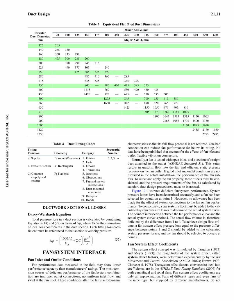
Flat Oval Ducts. To convert round ducts to flat oval sizes, useTable 3, which is based on Equation (26) (Heyt and Diaz 1975), thecircular equivalent of a flat oval duct for equal airflow, resistance,and length. Equations (18) and (19) must be used to determine fric-tion loss.
(26)
where AR is the cross-sectional area of flat oval duct defined as
AR = (πa2/4) + a(A – a) (27)
and the perimeter P is calculated by
Fig. 8 Pressure Loss Correction Factor for Flexible Duct NotFully Extended
Fig. 8 Pressure Loss Correction Factor for Flexible Duct Not Fully Extended
De1.30 ab( )0.625
a b+( )0.250--------------------------------=
De1.55AR
0.625
P0.250
-----------------------------=
Lice
nsed
for s
ingl
e us
er. ©
200
9 A
SH
RA
E, I
nc.

21.8 2009 ASHRAE Handbook—Fundamentals (SI)
Fig
. 9F
rict
ion
Cha
rt fo
r R
ound
Duc
t (ρ
= 0
.075
lbm
/ft3 1
.20
kg/m
3 an
d ε
= 0
.000
3 ft
Fig
. 9F
rict
ion
Cha
rt fo
r R
ound
Duc
t (ρ
= 1
.20
kg/m
3 an
d ε
= 0
.09
mm
)
Lice
nsed
for s
ingl
e us
er. ©
200
9 A
SH
RA
E, I
nc.

Duct Design 21.9
P = πa + 2(A – a) (28)
whereP = perimeter of flat oval duct, mmA = major axis of flat oval duct, mma = minor axis of flat oval duct, mm
DYNAMIC LOSSES
Dynamic losses result from flow disturbances caused by duct-mounted equipment and fittings (e.g., entries, exits, elbows, transi-tions, and junctions) that change the airflow path’s direction and/orarea. Idelchik et al. (1994) discuss parameters affecting fluid resis-tance of fittings and presents local loss coefficients in three forms:tables, curves, and equations.
Local Loss CoefficientsThe dimensionless coefficient C is used for fluid resistance,
because this coefficient has the same value in dynamically similarstreams (i.e., streams with geometrically similar stretches, equalReynolds numbers, and equal values of other criteria necessary fordynamic similarity). The fluid resistance coefficient represents theratio of total pressure loss to velocity pressure at the referencedcross section:
(29)
whereC = local loss coefficient, dimensionless
Δ pj = total pressure loss, Paρ = density, kg/m3
V = velocity, m/spv = velocity pressure, Pa
Dynamic losses occur along a duct length and cannot be sepa-rated from friction losses. For ease of calculation, dynamic lossesare assumed to be concentrated at a section (local) and exclude fric-tion. Frictional losses must be considered only for relatively longfittings. Generally, fitting friction losses are accounted for by mea-suring duct lengths from the centerline of one fitting to that of thenext fitting. For fittings closely coupled (less than six hydraulicdiameters apart), the flow pattern entering subsequent fittings dif-fers from the flow pattern used to determine loss coefficients. Ade-quate data for these situations are unavailable.
For all fittings, except junctions, calculate the total pressure lossΔ pj at a section by
Δ pj = Co pv,o (30)
where the subscript o is the cross section at which the velocity pres-sure is referenced. Dynamic loss is based on the actual velocity inthe duct, not the velocity in an equivalent circular duct. For the crosssection to reference a fitting loss coefficient, see step 4 in the sectionon HVAC Duct Design Procedures. Where necessary (e.g., unequal-area fittings), convert a loss coefficient from section o to section iusing Equation (31), where V is the velocity at the respective sec-tions.
(31)
For converging and diverging flow junctions, total pressurelosses through the straight (main) section are calculated as
Δ pj = Cc,s pv, c (32)
For total pressure losses through the branch section,
Δ pj = Cc,b pv,c (33)
where pv,c is the velocity pressure at the common section c, andCc,s and Cc,b are loss coefficients for the straight (main) andbranch flow paths, respectively, each referenced to the velocitypressure at section c. To convert junction local loss coefficientsreferenced to straight and branch velocity pressures, use the fol-lowing equation:
(34)
whereCi = local loss coefficient referenced to section being calculated (see
subscripts), dimensionlessCc,i = straight (Cc,s) or branch (Cc,b) local loss coefficient referenced to
dynamic pressure at common section, dimensionlessVi = velocity at section to which Ci is being referenced, m/sVc = velocity at common section, m/s
Subscripts:
b = branchs = straight (main) sectionc = common section
The junction of two parallel streams moving at different veloc-ities is characterized by turbulent mixing of the streams, accom-panied by pressure losses. In the course of this mixing, momentumis exchanged between particles moving at different velocities,resulting in equalization of the velocity distributions in the com-mon stream. The jet with higher velocity loses part of its kineticenergy by transmitting it to the slower jet. The loss in total pres-sure before and after mixing is always large and positive for thehigher-velocity jet, and increases with an increase in the amount ofenergy transmitted to the lower-velocity jet. Consequently, thelocal loss coefficient [Equation (29)] is always positive. Energystored in the lower-velocity jet increases because of mixing. Theloss in total pressure and the local loss coefficient can, therefore,also have negative values for the lower velocity jet (Idelchik et al.1994).
Duct Fitting DatabaseA duct fitting database that includes more than 220 round, flat
oval, and rectangular fittings is available from ASHRAE (2009).The fittings are numbered (coded) as shown in Table 4. Entries
and converging junctions are only in the exhaust/return portion ofsystems. Exits and diverging junctions are only in supply systems.Equal-area elbows, obstructions, and duct-mounted equipment arecommon to both supply and exhaust systems. Transitions andunequal-area elbows can be either supply or exhaust fittings. FittingED5-1 (see the section on Fitting Loss Coefficients) is an Exhaustfitting with a round shape (Diameter). The number 5 indicates thatthe fitting is a junction, and 1 is its sequential number. Fittings SR31and ER3-1 are Supply and Exhaust fittings, respectively. The Rindicates that the fitting is Rectangular, and the 3 identifies thefitting as an elbow. Note that the cross-sectional areas at sections 0and 1 are not equal (see the section on Fitting Loss Coefficients).Otherwise, the elbow would be a Common fitting such as CR3-6.Additional fittings are reproduced in the section on Fitting LossCoefficients to support the example design problems (see Table 10for Example 6; see Table 12 for Example 7).
Bends in Flexible DuctAbushakra et al. (2002) show that loss coefficients for bends in
flexible ductwork vary widely from condition to condition, with nouniform or consistent trends. Loss coefficients range from a low of0.87 to a high of 3.27. Flexible duct elbows should not be used inlieu of rigid elbows.
CpjΔ
ρ V 2 2⁄( )---------------------
pjΔ
pv---------= =
Ci
Co
Vi Vo⁄( )2----------------------=
Ci
Cc i,
Vi Vc⁄( )2----------------------=
Lice
nsed
for s
ingl
e us
er. ©
200
9 A
SH
RA
E, I
nc.

21.10 2009 ASHRAE Handbook—Fundamentals (SI)
Table 2 Circular Equivalents of Rectangular Duct for Equal Friction and Capacitya
Lgth Adj.b
Length of One Side of Rectangular Duct a, mm
100 125 150 175 200 225 250 275 300 350 400 450 500 550 600 650 700 750 800 900
Circular Duct Diameter, mm
100 109 125 122 137 150 133 150 164 175 143 161 177 191 200 152 172 189 204 219 225 161 181 200 216 232 246 250 169 190 210 228 244 259 273 275 176 199 220 238 256 272 287 301 300 183 207 229 248 266 283 299 314 328 350 195 222 245 267 286 305 322 339 354 383 400 207 235 260 283 305 325 343 361 378 409 437 450 217 247 274 299 321 343 363 382 400 433 464 492 500 227 258 287 313 337 360 381 401 420 455 488 518 547 550 236 269 299 326 352 375 398 419 439 477 511 543 573 601 600 245 279 310 339 365 390 414 436 457 496 533 567 598 628 656 650 253 289 321 351 378 404 429 452 474 515 553 589 622 653 683 711 700 261 298 331 362 391 418 443 467 490 533 573 610 644 677 708 737 765 750 268 306 341 373 402 430 457 482 506 550 592 630 666 700 732 763 792 820 800 275 314 350 383 414 442 470 496 520 567 609 649 687 722 755 787 818 847 875 900 289 330 367 402 435 465 494 522 548 597 643 686 726 763 799 833 866 897 927 9841000 301 344 384 420 454 486 517 546 574 626 674 719 762 802 840 876 911 944 976 10371100 313 358 399 437 473 506 538 569 598 652 703 751 795 838 878 916 953 988 1022 10861200 324 370 413 453 490 525 558 590 620 677 731 780 827 872 914 954 993 1030 1066 11331300 334 382 426 468 506 543 577 610 642 701 757 808 857 904 948 990 1031 1069 1107 11771400 344 394 439 482 522 559 595 629 662 724 781 835 886 934 980 1024 1066 1107 1146 12201500 353 404 452 495 536 575 612 648 681 745 805 860 913 963 1011 1057 1100 1143 1183 12601600 362 415 463 508 551 591 629 665 700 766 827 885 939 991 1041 1088 1133 1177 1219 12981700 371 425 475 521 564 605 644 682 718 785 849 908 964 1018 1069 1118 1164 1209 1253 13351800 379 434 485 533 577 619 660 698 735 804 869 930 988 1043 1096 1146 1195 1241 1286 13711900 387 444 496 544 590 663 674 713 751 823 889 952 1012 1068 1122 1174 1224 1271 1318 14052000 395 453 506 555 602 646 688 728 767 840 908 973 1034 1092 1147 1200 1252 1301 1348 14382100 402 461 516 566 614 659 702 743 782 857 927 993 1055 1115 1172 1226 1279 1329 1378 14702200 410 470 525 577 625 671 715 757 797 874 945 1013 1076 1137 1195 1251 1305 1356 1406 15012300 417 478 534 587 636 683 728 771 812 890 963 1031 1097 1159 1218 1275 1330 1383 1434 15322400 424 486 543 597 647 695 740 784 826 905 980 1050 1116 1180 1241 1299 1355 1409 1461 15612500 430 494 552 606 658 706 753 797 840 920 996 1068 1136 1200 1262 1322 1379 1434 1488 15892600 437 501 560 616 668 717 764 810 853 935 1012 1085 1154 1220 1283 1344 1402 1459 1513 16172700 443 509 569 625 678 728 776 822 866 950 1028 1102 1173 1240 1304 1366 1425 1483 1538 16442800 450 516 577 634 688 738 787 834 879 964 1043 1119 1190 1259 1324 1387 1447 1506 1562 16702900 456 523 585 643 697 749 798 845 891 977 1058 1135 1208 1277 1344 1408 1469 1529 1586 1696
Lgth Adj.b
Length of One Side of Rectangular Duct a, mm
1000 1100 1200 1300 1400 1500 1600 1700 1800 1900 2000 2100 2200 2300 2400 2500 2600 2700 2800 2900
Circular Duct Diameter, mm
1000 10931100 1146 12021200 1196 1256 13121300 1244 1306 1365 14211400 1289 1354 1416 1475 15301500 1332 1400 1464 1526 1584 16401600 1373 1444 1511 1574 1635 1693 17491700 1413 1486 1555 1621 1684 1745 1803 18581800 1451 1527 1598 1667 1732 1794 1854 1912 19681900 1488 1566 1640 1710 1778 1842 1904 1964 2021 20772000 1523 1604 1680 1753 1822 1889 1952 2014 2073 2131 21862100 1558 1640 1719 1793 1865 1933 1999 2063 2124 2183 2240 22962200 1591 1676 1756 1833 1906 1977 2044 2110 2173 2233 2292 2350 24052300 1623 1710 1793 1871 1947 2019 2088 2155 2220 2283 2343 2402 2459 25142400 1655 1744 1828 1909 1986 2060 2131 2200 2266 2330 2393 2453 2511 2568 26242500 1685 1776 1862 1945 2024 2100 2173 2243 2311 2377 2441 2502 2562 2621 2678 27332600 1715 1808 1896 1980 2061 2139 2213 2285 2355 2422 2487 2551 2612 2672 2730 2787 28422700 1744 1839 1929 2015 2097 2177 2253 2327 2398 2466 2533 2598 2661 2722 2782 2840 2896 29522800 1772 1869 1961 2048 2133 2214 2292 2367 2439 2510 2578 2644 2708 2771 2832 2891 2949 3006 30612900 1800 1898 1992 2081 2167 2250 2329 2406 2480 2552 2621 2689 2755 2819 2881 2941 3001 3058 3115 3170aTable based on De = 1.30(ab)0.625/(a + b)0.25. bLength adjacent side of rectangular duct b, mm.
Lice
nsed
for s
ingl
e us
er. ©
200
9 A
SH
RA
E, I
nc.
Duct Design 21.11
DUCTWORK SECTIONAL LOSSES
Darcy-Weisbach EquationTotal pressure loss in a duct section is calculated by combining
Equations (18) and (29) in terms of Δp, where ΣC is the summationof local loss coefficients in the duct section. Each fitting loss coef-ficient must be referenced to that section’s velocity pressure.
(35)
FAN/SYSTEM INTERFACEFan Inlet and Outlet Conditions
Fan performance data measured in the field may show lowerperformance capacity than manufacturers’ ratings. The most com-mon causes of deficient performance of the fan/system combina-tion are improper outlet connections, nonuniform inlet flow, andswirl at the fan inlet. These conditions alter the fan’s aerodynamic
characteristics so that its full flow potential is not realized. One badconnection can reduce fan performance far below its rating. Nodata have been published that account for the effects of fan inlet andoutlet flexible vibration connectors.
Normally, a fan is tested with open inlets and a section of straightduct attached to the outlet (ASHRAE Standard 51). This setupresults in uniform flow into the fan and efficient static pressurerecovery on the fan outlet. If good inlet and outlet conditions are notprovided in the actual installation, the performance of the fan suf-fers. To select and apply the fan properly, these effects must be con-sidered, and the pressure requirements of the fan, as calculated bystandard duct design procedures, must be increased.
Figure 10 illustrates deficient fan/system performance. Systempressure losses have been determined accurately, and a fan has beenselected for operation at point 1. However, no allowance has beenmade for the effect of system connections to the fan on fan perfor-mance. To compensate, a fan system effect must be added to the cal-culated system pressure losses to determine the actual system curve.The point of intersection between the fan performance curve and theactual system curve is point 4. The actual flow volume is, therefore,deficient by the difference from 1 to 4. To achieve design flow vol-ume, a fan system effect pressure loss equal to the pressure differ-ence between points 1 and 2 should be added to the calculatedsystem pressure losses, and the fan should be selected to operate atpoint 2.
Fan System Effect CoefficientsThe system effect concept was formulated by Farquhar (1973)
and Meyer (1973); the magnitudes of the system effect, calledsystem effect factors, were determined experimentally by the AirMovement and Control Association (AMCA 2007a; Brown 1973;Clarke et al. 1978). The system effect factors, converted to local losscoefficients, are in the ASHRAE Duct Fitting Database (2009) forboth centrifugal and axial fans. Fan system effect coefficients areonly an approximation. Fans of different types and even fans ofthe same type, but supplied by different manufacturers, do not
Table 3 Equivalent Flat Oval Duct Dimensions
CircularDuct Diameter,
mm
Minor Axis a, mm
70 100 125 150 175 200 250 275 300 325 350 375 400 450 500 550 600
Major Axis A, mm
125 205
140 265 180
160 360 235 190
180 475 300 235 200
200 380 290 245 215
224 490 375 305 — 240
250 475 385 325 290
280 485 410 360 — 285
315 635 525 — — 345 325
355 840 — 580 460 425 395 375
400 1115 — 760 — 530 490 460 435
450 1490 — 995 — 675 — 570 535 505
500 1275 — 845 — 700 655 615 580
560 1680 — 1085 — 890 820 765 720
630 1425 — 1150 1050 970 905 810
710 1505 1370 1260 1165 1025
800 1800 1645 1515 1315 1170 1065
900 2165 1985 1705 1500 1350
1000 2170 1895 1690
1120 2455 2170 1950
1250 2795 2495
Table 4 Duct Fitting Codes
FittingFunction Geometry Category
Sequential Number
S: Supply D: round (Diameter) 1. Entries 1,2,3...n2. Exits
E: Exhaust/Return R: Rectangular 3. Elbows4. Transitions
C: Common (supply and return)
F: Flat oval 5. Junctions6. Obstructions7. Fan and system
interactions8. Duct-mounted
equipment9. Dampers
10. Hoods
pΔ1000 f L
Dh------------------- ΣC+
⎝ ⎠⎜ ⎟⎛ ⎞ ρV
2
2---------
⎝ ⎠⎜ ⎟⎛ ⎞
=
Lice
nsed
for s
ingl
e us
er. ©
200
9 A
SH
RA
E, I
nc.

21.12 2009 ASHRAE Handbook—Fundamentals (SI)
necessarily react to a system in the same way. Therefore, judgmentbased on experience must be applied to any design.
Fan Outlet Conditions. Fans intended primarily for duct sys-tems are usually tested with an outlet duct in place (ASHRAE Stan-dard 51). Figure 11 shows the changes in velocity profiles at various
distances from the fan outlet. For 100% recovery, the duct, includ-ing transition, must meet the requirements for 100% effective ductlength [Le (Figure 11)], which is calculated as follows:
For Vo > 13 m/s,
(36)
For Vo ≤ 13 m/s,
(37)
whereVo = duct velocity, m/sLe = effective duct length, mAo = duct area, mm2
As illustrated by Fitting SR7-1 in the section on Fitting LossCoefficients, centrifugal fans should not abruptly discharge to theatmosphere. A diffuser design should be selected from FittingSR7-2 (see the section on Fitting Loss Coefficients) or SR7-3 [seeASHRAE (2009)].
Fan Inlet Conditions. For rated performance, air must enter thefan uniformly over the inlet area in an axial direction without prero-tation. Nonuniform flow into the inlet is the most common cause ofreduced fan performance. Such inlet conditions are not equivalent toa simple increase in system resistance; therefore, they cannot betreated as a percentage decrease in the flow and pressure from thefan. A poor inlet condition results in an entirely new fan perfor-mance. An elbow at the fan inlet, for example Fitting ED7-2 (see the
Fig. 10 Deficient System Performance with System EffectIgnored
Fig. 10 Deficient System Performance with System Effect Ignored
Fig. 11 Establishment of Uniform Velocity Profile in Straight Fan Outlet Duct
Fig. 11 Establishment of Uniform Velocity Profile in Straight Fan Outlet Duct(Adapted by permission from AMCA Publication 201)
Le
Vo Ao
4500------------------=
Le
Ao
350-----------=
Lice
nsed
for s
ingl
e us
er. ©
200
9 A
SH
RA
E, I
nc.

Duct Design 21.13
section on Fitting Loss Coefficients), causes turbulence and unevenflow into the fan impeller. Losses from the fan system effect can beeliminated by including an adequate length of straight duct betweenthe elbow and the fan inlet.
The ideal inlet condition allows air to enter axially and uniformlywithout spin. A spin in the same direction as the impeller rotation re-duces the pressure/volume curve by an amount dependent on the vor-tex’s intensity. A counterrotating vortex at the inlet slightly increasesthe pressure/volume curve, but the power is increased substantially.
Inlet spin may arise from many different approach conditions, andsometimes the cause is not obvious. Inlet spin can be avoided by pro-viding an adequate length of straight duct between the elbow and thefan inlet. Figure 12 illustrates some common duct connections thatcause inlet spin and includes recommendations for correcting spin.
Fans within plenums and cabinets or next to walls should belocated so that air may flow unobstructed into the inlets. Fan perfor-mance is reduced if the space between the fan inlet and the enclosureis too restrictive. System effect coefficients for fans in an enclosureor adjacent to walls are listed under Fitting ED7-1 (see the sectionon Fitting Loss Coefficients). How the airstream enters an enclosurein relation to the fan inlets also affects fan performance. Plenum orenclosure inlets or walls that are not symmetrical with the fan inletscause uneven flow and/or inlet spin.
Testing, Adjusting, and Balancing ConsiderationsFan system effects (FSEs) are not only to be used in conjunction
with the system resistance characteristics in the fan selection pro-cess, but are also applied in the calculations of the results of testing,adjusting, and balancing (TAB) field tests to allow direct compari-son to design calculations and/or fan performance data. Fan inletswirl and the effect on system performance of poor fan inlet and out-let ductwork connections cannot be measured directly. Poor inletflow patterns affect fan performance within the impeller wheel (cen-trifugal fan) or wheel rotor impeller (axial fan), while the fan outletsystem effect is flow instability and turbulence within the fan dis-charge ductwork.
The static pressure at the fan inlet and the static pressure at thefan outlet may be measured directly in some systems. In most cases,static pressure measurements for use in determining fan total (orstatic) pressure will not be made directly at the fan inlet and outlet,but at locations a relatively short distance from the fan inlet anddownstream from the fan outlet. To calculate fan total pressure forthis case from field measurements, use Equation (38), where Δpx–yis the summation of calculated total pressure losses between the faninlet and outlet sections noted. Plane 3 is used to determine airflowrate. If necessary, use Equation (17) to calculate fan static pressureknowing fan total pressure. For locating measurement planes andcalculation procedures, consult AMCA Publication 203 (AMCA2007b).
Pt = ( ps,5 + pv,5) + Δ p2-5 + FSE2 + ( ps,4 + pv,4) + Δp4-1 + FSE1 + FSE1, sw (38)
wherePt = fan total pressure, Paps = static pressure, Papv = velocity pressure, Pa
FSE = fan system effect, PaΔ px-y = summarization of total pressure losses between planes x and
y, Pa
Subscripts [numerical subscripts same as used by AMCA (2007b)]:1 = fan inlet2 = fan outlet3 = plane of airflow measurement4 = plane of static pressure measurement upstream of fan5 = plane of static pressure measurement downstream of fan
sw = swirl
DUCT SYSTEM DESIGN
DESIGN CONSIDERATIONS
Space Pressure RelationshipsSpace pressure is determined by fan location and duct system
arrangement. For example, a supply fan that pumps air into a spaceincreases space pressure; an exhaust fan reduces space pressure. Ifboth supply and exhaust fans are used, space pressure depends onthe relative capacity of the fans. Space pressure is positive if supplyexceeds exhaust and negative if exhaust exceeds supply (Osborne1966). System pressure variations caused by wind can be minimizedor eliminated by careful selection of intake air and exhaust ventlocations (see Chapter 24).
Fire and Smoke ManagementBecause duct systems can convey smoke, hot gases, and fire from
one area to another and can accelerate a fire within the system, fireprotection is an essential part of air-conditioning and ventilationsystem design. Generally, fire safety codes require compliance withthe standards of national organizations. NFPA Standard 90A exam-ines fire safety requirements for (1) ducts, connectors, and appurte-nances; (2) plenums and corridors; (3) air outlets, air inlets, andfresh air intakes; (4) air filters; (5) fans; (6) electric wiring andequipment; (7) air-cooling and -heating equipment; (8) buildingconstruction, including protection of penetrations; and (9) controls,including smoke control.
Fire safety codes often refer to the testing and labeling practicesof nationally recognized laboratories, such as Factory Mutual andUnderwriters Laboratories (UL). UL’s annual Building MaterialsDirectory lists fire and smoke dampers that have been tested andmeet the requirements of UL Standards 555 and 555S. This direc-tory also summarizes maximum allowable sizes for individualdampers and assemblies of these dampers. Fire dampers are 1.5 h or3 h fire-rated. Smoke dampers are classified by (1) temperature deg-radation [ambient air or high temperature (120°C minimum)] and
Fig. 12 Inlet Duct Connections Causing Inlet Spin and Cor-rections for Inlet Spin
Fig. 12 Inlet Duct Connections Causing Inlet Spin and Corrections for Inlet Spin
(Adapted by permission from AMCA Publication 201)
Lice
nsed
for s
ingl
e us
er. ©
200
9 A
SH
RA
E, I
nc.

21.14 2009 ASHRAE Handbook—Fundamentals (SI)
(2) leakage at 250 and 1000 Pa pressure difference (2 and 3 kPaclassification optional). Smoke dampers are tested under conditionsof maximum airflow. UL’s annual Fire Resistance Directory listsfire resistances of floor/roof and ceiling assemblies with and with-out ceiling fire dampers.
For a more detailed presentation of fire protection, see the NFPA(2008) Fire Protection Handbook, Chapter 52 of the 2007 ASHRAEHandbook—HVAC Applications, and Klote and Milke (2002).
Duct InsulationIn all new construction (except low-rise residential buildings),
air-handling ducts and plenums that are part of an HVAC air distri-bution system should be thermally insulated in accordance withASHRAE Standard 90.1. Duct insulation for new low-rise residen-tial buildings should comply with ASHRAE Standard 90.2. Exist-ing buildings should meet requirements of ASHRAE Standard 100.In all cases, thermal insulation should meet local code requirements.Insulation thicknesses in these standards are minimum values; eco-nomic and thermal considerations may justify higher insulation lev-els. Additional insulation, vapor retarders, or both may be requiredto limit vapor transmission and condensation.
Duct heat gains or losses must be known to calculate supply airquantities, supply air temperatures, and coil loads. To estimate ductheat transfer and entering or leaving air temperatures, refer to Chap-ter 23.
Duct System LeakageIt is recommended that all transverse joints, longitudinal seams,
and ductwork penetrations be sealed. Longitudinal seams arejoints oriented in the direction of airflow. Duct wall penetrationsare openings made by screws, non-self-sealing fasteners, pipe, tub-ing, rods, and wire. All other connections are considered transversejoints, which are connections of two duct or fitting elements ori-ented perpendicular to flow (e.g., spin-ins, taps, branch connections,duct connections to equipment). System (ductwork and equipment)leakage should be tested to verify the installing contractor’s work-manship and sealing practices.
Leakage in all unsealed ducts varies considerably with the fabri-cating machinery used, material thickness, assembly methods, andinstallation workmanship. For sealed ducts, a wide variety of sealingmethods and products exists. Sealed and unsealed duct leakage tests(AISI/SMACNA 1972; ASHRAE/SMACNA/TIMA 1985; Swimand Griggs 1995) confirmed that longitudinal seam, transverse joint,and assembled duct leakage can be represented by Equation (39) andthat, for the same construction, leakage is not significantly differentin negative and positive modes. Table 5 presents a range of leakagerates for longitudinal seams commonly used in metal duct construc-tion. Longitudinal seam leakage for unsealed or unwelded metalducts is about 10 to 15% of total duct leakage.
Q = CΔ pnN (39)
whereQ = duct leakage rate, L/(s·m2)C = constant reflecting area characteristics of leakage path
Δ ps = static pressure differential from duct interior to exterior, PaN = exponent relating turbulent or laminar flow in leakage path
The AISI/ASHRAE/SMACNA/TIMA data showed that ductleakage (equipment not included) is best predicted by duct surfacearea and pressure, because surface area highlights the effect ofsystem size. Duct leakage were grouped into a geometric series ofleakage classes CL (Figure 13) based on Equation (40), where theexponent N is assumed to be 0.65. Table 6 shows leakage classes forcommonly used duct construction and sealing practices (equipmentleakage excluded).
CL = Q/Δ pn0.65 (40)
whereQ = leakage rate, L/(s·m2) (surface area)
CL = leakage class, L/(s·m2) duct surface at 1 Pa static pressure
Effects of equipment leakage (e.g., through dampers, access doors,VAV boxes, diffusers) should be anticipated. Ductwork should notbe expected to compensate for equipment leakage. Terminal unitsmay leak 1 to 2% of their maximum flow. Use Table 6 to calculateallowable ductwork leakage for a system. Leakage classes listed inTable 6 are for a specific duct type, not a system with a variety ofduct types. When several pressure classifications or shapes occur ina system, ductwork in each class or shape should be evaluated inde-pendently to find an aggregate leakage for the system. System leak-age (ductwork plus equipment) values for use in specificationsshould be in terms of L/s at the pressure(s) leakage was determined.The estimated percent leakage for any section of ductwork can bedetermined from Table 7 (equipment leakage not included).
Limited performance standards for metal duct sealants and tapesexist. For guidance in their selection and use, refer to SMACNA’s
Table 5 Unsealed Longitudinal Seam Leakage, Metal Ducts
Type of Duct/Seam
Leakage, L per metre Seam Length*
Range Average
RectangularPittsburgh lock
26 gage 0.015 to 0.03 0.02522 gage 0.0015 to 0.003 0.0025
Button punch snaplock26 gage 0.05 to 0.23 0.1222 gage NA (1 test) 0.005
RoundSpiral (26 gage) NA (1 test) 0.023Snaplock 0.06 to 0.22 0.17Grooved 0.17 to 0.28 0.19
*Leakage rate is at 250 Pa static pressure.
Fig. 13 Duct Leakage Classifications
Fig. 13 Duct Leakage Classifications
Lice
nsed
for s
ingl
e us
er. ©
200
9 A
SH
RA
E, I
nc.

Duct Design 21.15 HVAC Duct Construction Standards (2005). Fibrous glass ducts and
their closure systems are covered by UL Standards 181 and 181A.For fibrous glass duct construction standards, consult NAIMA (2002)and SMACNA (2003). Flexible duct performance and installation
standards are covered by UL Standards 181 and 181B and ADC(2003). Soldered or welded duct construction is necessary wheresealants are not suitable. Sealants used on exterior ducts must beresistant to weather, temperature cycles, sunlight, and ozone.
Shaft and compartment pressure changes affect duct leakage andare important to health and safety in the design and operation ofcontaminant and smoke control systems. Shafts should not be usedfor supply, return, and/or exhaust air without accounting for theirleakage rates. Airflow around buildings, building component leak-age, and the distribution of inside and outside pressures over theheight of a building, including shafts, are discussed in Chapters 16and 24.
System Component Design VelocitiesTable 8 summarizes face velocities for HVAC components in
built-up systems. In most cases, the values are abstracted from per-tinent chapters in the 2008 ASHRAE Handbook—HVAC Systemsand Equipment; final selection of components should be based ondata in these chapters or, preferably, from manufacturers.
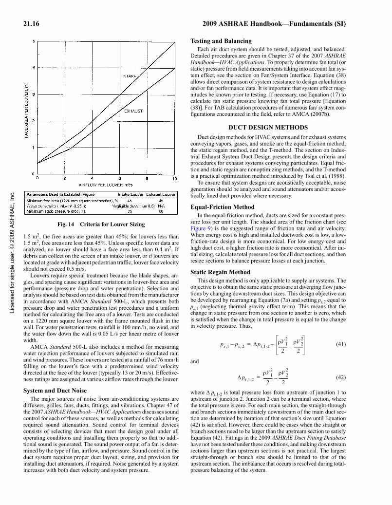
Use Figure 14 for preliminary sizing of air intake and exhaustlouvers. For air quantities greater than 3300 L/s per louver, the airintake gross louver openings are based on 2 m/s; for exhaust lou-vers, 2.5 m/s is used for air quantities of 2400 L/s per louver andgreater. For smaller air quantities, refer to Figure 14. These criteriaare presented on a per-louver basis (i.e., each louver in a bank oflouvers) to include each louver frame. Representative production-run louvers were used in establishing Figure 14, and all data usedwere based on AMCA Standard 500-L tests. For louvers larger than
Table 6 Duct Leakage Classificationa
Duct Type
Sealedb,c Unsealedc
Predicted Leakage Class CL
Leakage Rate,
L/(s·m2) at 250 Pa
Predicted Leakage Class CL
Leakage Rate,
L/(s·m2) at 250 Pa
Metal (flexible excluded)Round and flat oval 4 0.14 42 1.5
(8 to 99) (0.3 to 3.6)Rectangular 17 0.62 68 2.5
(17 to 155) (0.6 to 5.6)Flexible
Metal, aluminum 11 0.40 42 1.5(17 to 76) (0.6 to 2.8)
Nonmetal 17 0.62 30 1.5(6 to 76) (0.2 to 2.8)
Fibrous glassRound 4 0.14 NA NARectangular 8 0.29 NA NA
aLeakage classes here are averages based on tests conducted by AISI/SMACNA(1972), ASHRAE/SMACNA/TIMA (1985), and Swim and Griggs (1995).
b“Sealed” leakage classes assume that, for metal ducts, all transverse joints, seams, andopenings in duct wall are sealed.
cLeakage classes anticipate about 0.82 joints per metre of duct. For systems with a highfitting-to-straight-duct ratio, greater leakage occurs in both sealed and unsealed con-ditions.
Table 7 Leakage as Percentage of Airflowa,b
Leakage Class
System L/s per m2 Duct Surfacec
Static Pressure, Pa
125 250 500 750 1000 1500
68 10 15 24 38 49 59 7712.7 12 19 30 39 47 6215 10 16 25 33 39 5120 7.7 12 19 25 30 3825 6.1 9.6 15 20 24 31
34 10 7.7 12 19 25 30 3812.7 6.1 9.6 15 20 24 3115 5.1 8.0 13 16 20 2620 3.8 6.0 9.4 12 15 1925 3.1 4.8 7.5 9.8 12 15
17 10 3.8 6 9.4 12 15 1912.7 3.1 4.8 7.5 9.8 12 1515 2.6 4.0 6.3 8.2 9.8 1320 1.9 3.0 4.7 6.1 7.4 9.625 1.5 2.4 3.8 4.9 5.9 7.7
8 10 1.9 3 4.7 6.1 7.4 9.612.7 1.5 2.4 3.8 4.9 5.9 7.715 1.3 2.0 3.1 4.1 4.9 6.420 1.0 1.5 2.4 3.1 3.7 4.825 0.8 1.2 1.9 2.4 3.0 3.8
4 10 1.0 1.5 2.4 3.1 3.7 4.812.7 0.8 1.2 1.9 2.4 3.0 3.815 0.6 1.0 1.6 2.0 2.5 3.220 0.5 0.8 1.3 1.6 2.0 2.625 0.4 0.6 0.9 1.2 1.5 1.9
aAdapted with permission from HVAC Air Duct Leakage Test Manual (SMACNA1985, Appendix A).
bPercentage applies to airflow entering a section of duct operating at an assumed pres-sure equal to average of upstream and downstream pressures.
cRatios in this column are typical of fan volumetric flow rate divided by total system surface. Portions of systems may vary from these averages.
Table 8 Typical Design Velocities for HVAC Components
Duct Element Face Velocity, m/s
Louversa
Intake3300 L/s and greater 2Less than 3300 L/s See Figure 14
Exhaust2400 L/s and greater 2.5Less than2400 L/s See Figure 14
Filtersb
Panel filtersViscous impingement 1 to 4Dry-type, extended-surface
Flat (low efficiency) Duct velocityPleated media (intermediate efficiency) Up to 3.8HEPA 1.3
Renewable media filtersMoving-curtain viscous impingement 2.5Moving-curtain dry media 1
Electronic air cleanersIonizing type 0.8 to 1.8
Heating Coilsc
Steam and hot water 2.5 to 51 min., 8 max.
ElectricOpen wire Refer to mfg. dataFinned tubular Refer to mfg. data
Dehumidifying Coilsd 2 to 3
Air Washerse
Spray type Refer to mfg. dataCell type Refer to mfg. dataHigh-velocity spray type 6 to 9
aBased on assumptions presented in text.bAbstracted from Ch. 28, 2008 ASHRAE Handbook—HVAC Systems and Equipment.cAbstracted from Ch. 26, 2008 ASHRAE Handbook—HVAC Systems and Equipment.dAbstracted from Ch. 22, 2008 ASHRAE Handbook—HVAC Systems and Equipment.eAbstracted from Ch. 40, 2008 ASHRAE Handbook—HVAC Systems and Equipment.
Lice
nsed
for s
ingl
e us
er. ©
200
9 A
SH
RA
E, I
nc.
21.16 2009 ASHRAE Handbook—Fundamentals (SI)
1.5 m2, the free areas are greater than 45%; for louvers less than1.5 m2, free areas are less than 45%. Unless specific louver data areanalyzed, no louver should have a face area less than 0.4 m2. Ifdebris can collect on the screen of an intake louver, or if louvers arelocated at grade with adjacent pedestrian traffic, louver face velocityshould not exceed 0.5 m/s.
Louvers require special treatment because the blade shapes, an-gles, and spacing cause significant variations in louver-free area andperformance (pressure drop and water penetration). Selection andanalysis should be based on test data obtained from the manufacturerin accordance with AMCA Standard 500-L, which presents bothpressure drop and water penetration test procedures and a uniformmethod for calculating the free area of a louver. Tests are conductedon a 1220 mm square louver with the frame mounted flush in thewall. For water penetration tests, rainfall is 100 mm/h, no wind, andthe water flow down the wall is 0.05 L/s per linear metre of louverwidth.
AMCA Standard 500-L also includes a method for measuringwater rejection performance of louvers subjected to simulated rainand wind pressures. These louvers are tested at a rainfall of 76 mm/hfalling on the louver’s face with a predetermined wind velocitydirected at the face of the louver (typically 13 or 20 m/s). Effective-ness ratings are assigned at various airflow rates through the louver.
System and Duct NoiseThe major sources of noise from air-conditioning systems are
diffusers, grilles, fans, ducts, fittings, and vibrations. Chapter 47 ofthe 2007 ASHRAE Handbook—HVAC Applications discusses soundcontrol for each of these sources, as well as methods for calculatingrequired sound attenuation. Sound control for terminal devicesconsists of selecting devices that meet the design goal under alloperating conditions and installing them properly so that no addi-tional sound is generated. The sound power output of a fan is deter-mined by the type of fan, airflow, and pressure. Sound control in theduct system requires proper duct layout, sizing, and provision forinstalling duct attenuators, if required. Noise generated by a systemincreases with both duct velocity and system pressure.
Testing and BalancingEach air duct system should be tested, adjusted, and balanced.
Detailed procedures are given in Chapter 37 of the 2007 ASHRAEHandbook—HVAC Applications. To properly determine fan total (orstatic) pressure from field measurements taking into account fan sys-tem effect, see the section on Fan/System Interface. Equation (38)allows direct comparison of system resistance to design calculationsand/or fan performance data. It is important that system effect mag-nitudes be known prior to testing. If necessary, use Equation (17) tocalculate fan static pressure knowing fan total pressure [Equation(38)]. For TAB calculation procedures of numerous fan/ system con-figurations encountered in the field, refer to AMCA (2007b).
DUCT DESIGN METHODS
Duct design methods for HVAC systems and for exhaust systemsconveying vapors, gases, and smoke are the equal-friction method,the static regain method, and the T-method. The section on Indus-trial Exhaust System Duct Design presents the design criteria andprocedures for exhaust systems conveying particulates. Equal fric-tion and static regain are nonoptimizing methods, and the T-methodis a practical optimization method introduced by Tsal et al. (1988).
To ensure that system designs are acoustically acceptable, noisegeneration should be analyzed and sound attenuators and/or acous-tically lined duct provided where necessary.
Equal-Friction MethodIn the equal-friction method, ducts are sized for a constant pres-
sure loss per unit length. The shaded area of the friction chart (seeFigure 9) is the suggested range of friction rate and air velocity.When energy cost is high and installed ductwork cost is low, a low-friction-rate design is more economical. For low energy cost andhigh duct cost, a higher friction rate is more economical. After ini-tial sizing, calculate total pressure loss for all duct sections, and thenresize sections to balance pressure losses at each junction.
Static Regain MethodThis design method is only applicable to supply air systems. The
objective is to obtain the same static pressure at diverging flow junc-tions by changing downstream duct sizes. This design objective canbe developed by rearranging Equation (7a) and setting ps,2 equal tops,1 (neglecting thermal gravity effect term). This means that thechange in static pressure from one section to another is zero, whichis satisfied when the change in total pressure is equal to the changein velocity pressure. Thus,
(41)
and
(42)
where Δ pt,1-2 is total pressure loss from upstream of junction 1 toupstream of junction 2. Junction 2 can be a terminal section, wherethe total pressure is zero. For each main section, the straight-throughand branch sections immediately downstream of the main duct sec-tion are determined by iteration of that section’s size until Equation(42) is satisfied. However, there could be cases when the straight orbranch sections need to be larger than the upstream section to satisfyEquation (42). Fittings in the 2009 ASHRAE Duct Fitting Databasehave not been tested under these conditions, and making downstreamsections larger than upstream sections is not practical. The largeststraight-through or branch size should be limited to that of theupstream section. The imbalance that occurs is resolved during total-pressure balancing of the system.
Fig. 14 Criteria for Louver Sizing
Fig. 14 Criteria for Louver Sizing
ps 1, ps 2,– pt 1-2,Δ ρV 12
2---------
ρV 22
2---------––=
pt 1-2,ΔρV 1
2
2---------
ρV 22
2---------–=
Lice
nsed
for s
ingl
e us
er. ©
200
9 A
SH
RA
E, I
nc.

Duct Design 21.17 To start system design, a maximum velocity is selected for the
root section (duct section downstream of a fan). In Figure 16, sec-tion 19 is the root for the supply air subsystem. The shaded area onthe friction chart (see Figure 9) is the suggested range of air velocity.When energy cost is high and installed ductwork cost is low, a lowerinitial velocity is more economical. For low energy cost and highduct cost, a higher velocity is more economical.
Because terminal sections often require additional static pres-sure to operate VAV terminal boxes properly, that static pressurerequirement is added into the section after it is sized using staticregain. Otherwise, the downstream section could be larger than theupstream section. For calculating duct sizes, the total pressurelosses of grilles, registers, diffusers, or constant-volume (CV) ter-minal boxes should be included in the sizing iterations.
Total Pressure Balancing. After completing duct sizing by thestatic regain method, any residual unbalance can be reduced or elim-inated by calculating the system’s total pressure (pressure requiredin the critical paths) and changing duct sizes or fittings in other pathsto increase the paths’ total pressure to approximate what is neededin the critical paths.
T-MethodT-method optimization (Tsal et al. 1988) is a dynamic program-
ming procedure based on Bellman’s (1957) tee-staging idea, exceptthat phase-level vector tracing is eliminated by optimizing locally ateach stage. This modification reduces the number of calculations,but requires iteration.
Ductwork sizes are determined by minimizing the objectivefunction:
E = Ep(PWEF) + Es (43)
whereE = present-worth owning and operating cost
Ep = first-year energy costEs = initial cost
PWEF = present worth escalation factor (Smith 1968), dimensionless
The objective function includes both initial system cost and pres-ent worth of energy. Hours of operation, annual escalation and inter-est rates, and amortization period are also required for optimization.
The following constraints are necessary for duct optimization(Tsal and Adler 1987):
• Continuity. For each node, flow in equals flow out.• Pressure balancing. Total pressure loss in each path must equal
fan total pressure; or, in effect, at any junction, total pressure lossfor all paths is the same.
• Nominal duct size. Ducts are constructed in discrete, nominalsizes. Each diameter of a round duct or height and width of a rect-angular duct is rounded to the nearest increment, usually 25 or50 mm, or according to ISO standards where applicable. If alower nominal size is selected, initial cost decreases, but pressureloss increases and may exceed the fan pressure. If a higher nom-inal size is selected, the opposite is true: initial cost increases, butsection pressure loss decreases. However, this lower pressure atone section may allow smaller ducts to be selected for sectionsthat follow. Therefore, optimization must consider size rounding.
• Air velocity restriction. Maximum allowable velocity is an acous-tic limitation (ductwork regenerated noise).
• Construction restriction. Architectural limits may restrict ductsizes. If air velocity or construction constraints are violated dur-ing an iteration, a duct size must be calculated. Pressure loss cal-culated for this preselected duct size is considered a fixed loss.
T-method simulation, developed by Tsal et al. (1990), deter-mines the flow in each duct section of an existing system with aknown operating fan performance curve. The simulation version of
the T-method converges very efficiently. Usually three iterations aresufficient to obtain a solution with a high degree of accuracy.
Many HVAC problems require duct system simulation. In addi-tion to the following concerns that can be clarified by simulation,the T-method is an excellent design tool for simulating flow distri-bution within a system with various modes of operation.
• Flow distribution in a VAV system caused by terminal box flowdiversity
• Airflow redistribution caused by HVAC system additions and/ormodifications
• System airflow analysis for partially occupied buildings• Necessity to replace fans and/or motors when retrofitting an air
distribution system• Multiple-fan system operating condition when one or more fans
shut down• Pressure differences between adjacent confined spaces in a nuclear
facility when a design basis accident (DBA) occurs (Farajian et al.1992)
• Smoke management system performance during a fire, whensome fire/smoke dampers close and others remain open
Availability. Software for T-method optimization is under devel-opment to identify optimum duct design, considering energy, oper-ation, and construction costs.
BALANCING DAMPERS
Constant-Volume (CV) SystemsDampers should be provided throughout CV systems. Systems
designed using the inherently non-self-balancing equal-frictionmethod should have balancing dampers at each branch throughoutthe system, unless sections are resized to balance pressure losses ateach junction. Self-balancing design methods, such as static regainand the T-method, produce fairly well-balanced systems and theo-retically do not need balancing dampers; however, because of theaccuracy limitations of fitting data (loss coefficients), use of fittingsfor which no data are available, and effects of close-coupled fittings,dampers should be provided.
Variable-Air-Volume (VAV) SystemsVAV systems in balance at design loads will not be in balance at
part-load conditions, because there is no single critical path in VAVsystems. The critical path is dynamic and continually changing asloads on a building change. In general, balancing dampers are notneeded for systems designed by the static regain or T-method,because these design methods are self-balancing at design loads andVAV boxes compensate for inaccuracy in fitting data or data inac-curacy caused by close-coupled fittings (at design loads) and systempressure variation (at part loads). Balancing dampers, however, arerequired for systems designed using the non-self-balancing equal-friction method. For systems designed using any method, dampersshould not be installed in the inlets to VAV boxes.
For any design method, VAV terminal units may have upstreamstatic pressures higher than for which the box is rated, thus possiblyintroducing noise into occupied spaces. In these cases, control algo-rithms can poll the VAV boxes and drive the duct static pressure tothe minimum set point required to keep at least one unit at starvation(open) at any given time. Upstream static pressure should always bekept at a minimum that is easy for the VAV box to control. Becausethere may be large differences in static pressure at riser takeoffsserving many floors from a single air handler, manual dampersshould be provided at each floor takeoff so that testing, adjusting,and balancing (TAB) contractors can field-adjust them after con-struction. Alternatively, these takeoff dampers could also be dynam-ically controlled to adjust the downstream static pressure applied tothe VAV boxes, while simultaneously driving the air handler to thelowest possible static pressure set point.
Lice
nsed
for s
ingl
e us
er. ©
200
9 A
SH
RA
E, I
nc.

21.18 2009 ASHRAE Handbook—Fundamentals (SI)
Silencers downstream of VAV terminal units should not be nec-essary if the VAV box damper is operating at nearly open conditions.Their use in this location should be based on careful acoustical anal-ysis, because silencers add total pressure to the system and thereforecreate more system noise by causing air handlers to operate athigher speeds for a given airflow.
HVAC DUCT DESIGN PROCEDURES
The general procedure for HVAC system duct design is as follows:
1. Study the building plans, and arrange supply and return outlets toprovide proper distribution of air in each space. Adjust calcu-lated air quantities for duct heat gains or losses and duct leakage.Also, adjust supply, return, and/or exhaust air quantities to meetspace pressurization requirements.
2. Select outlet sizes from manufacturers’ data (see Chapter 20).3. Sketch the duct system, connecting supply outlets and return
intakes with the air-handling units/air conditioners. Use rigidround ducts, minimize the number of fittings, and avoid close-coupled fittings because little is known about the resulting loss
coefficients. If space is restricted and a properly designed roundduct is too large, the next best option to minimize leakage andpressure losses is to use flat oval ductwork. Multiple runs ofround duct should also be considered. Limit flexible duct to thefinal 1.5 m of connections to diffusers and terminal boxes, withno more than 5% compression. They should be installed withoutkinks or crimps, and no more offset between the diffuser andrigid duct than 1/8th the diffuser neck diameter to prevent a sig-nificant increase in noise level (see Figure 11 in Chapter 47 ofthe 2007 ASHRAE Handbook—HVAC Applications).
4. Divide the system into sections and number each section. A ductsystem should be divided at all points where flow, size, or shapechanges. Assign fittings to the section toward the supply andreturn (or exhaust) terminals. The following examples are for thefittings identified for Example 6 (Figure 15), and system sectionnumbers assigned (Figure 16). For converging flow fitting 3,assign the straight-through flow to section 1 (toward terminal 1),and the branch to section 2 (toward terminal 4). For divergingflow fitting 24, assign the straight-through flow to section 13(toward terminals 26 and 29) and the branch to section 10
Fig. 15 Schematic for Example 8
Fig. 15 Schematic for Example 6
Lice
nsed
for s
ingl
e us
er. ©
200
9 A
SH
RA
E, I
nc.
Duct Design 21.19
(toward terminals 43 and 44). For transition fitting 11, assign thefitting to upstream section 4 [toward terminal 9 (intake louver)].For fitting 20, assign the unequal area elbow to downstreamsection 9 (toward diffusers 43 and 44). The fan outlet diffuser,fitting 42, is assigned to section 19 (again, toward the supplyduct terminals).
5. Size ducts by the selected design method. Calculate system totalpressure loss; then select the fan (refer to Chapter 20 of the 2008ASHRAE Handbook—HVAC Systems and Equipment).
6. Lay out the system in detail. If duct routing and fittings vary sig-nificantly from the original design, recalculate pressure losses.Reselect the fan if necessary.
7. Resize duct sections to approximately balance pressures at eachjunction.
8. Analyze the design for objectionable noise levels, and specifylined duct, double-wall duct, and sound attenuators as necessary.Refer to the section on System and Duct Noise.
Example 6. For the system illustrated by Figures 15 and 16, size the duct-work by the equal-friction method, and pressure-balance the system bychanging duct sizes (use 10 mm increments for rectangular, and avail-able spiral duct forming heads: 80, 100, 125, 140, 150, 160, 180, 200,224, 250, 280, 300, 315, 355, 400, 450, 500, 560, 600, 630, 710, 800,900, 1000, 1120, 1250, 1300, 1400, 1500, 1600, 1800, 2000, 2100,2200, 2300, 2400, and 2500 mm). Determine system resistance andtotal pressure unbalance at junctions. Airflow quantities are actual val-ues adjusted for heat gains or losses, and ductwork is sealed (assume noleakage), galvanized steel ducts with transverse joints on 1200 mm cen-ters (ε = 0.09 mm). Air is at standard conditions (1.204 kg/m3 density).
Because Figure 15 is intended to illustrate calculation procedures,its duct layout is not typical of any real duct system. The layoutincludes fittings from the local loss coefficient tables, with emphasis onconverging and diverging tees and various types of entries and dis-charges. The supply system is constructed of rectangular ductwork; thereturn system, round ductwork.
Solution: See Figure 16 for section numbers assigned to the system.Duct sections are sized within the suggested range of friction rate shownon the friction chart (see Figure 9). Tables 9 and 10 give total pressureloss calculations and the supporting summary of loss coefficients by sec-tions. Straight-duct friction factor and pressure loss were calculated byEquations (18) and (19). Fitting loss coefficients are from the 2009ASHRAE Duct Fitting Database. Loss coefficients were calculated auto-matically by the database program (not by manual interpolation). Pres-sure loss values in Table 9 for diffusers (fittings 43 and 44), louver(fitting 9), and air-measuring station (fitting 46) are manufacturers’ data.
Pressure unbalance at junctions is shown in Figure 17, the totalpressure grade line for the system. System resistance Pt is 704 Pa.Noise levels and the need for sound attenuation were not evaluated. Tocalculate the fan static pressure, use Equation (17):
Ps = 704 – 119 = 585 Pa
where 119 Pa is the fan outlet velocity pressure.
INDUSTRIAL EXHAUST SYSTEM DUCT DESIGN
Chapter 30 of the 2007 ASHRAE Handbook—HVAC Applicationsdiscusses design criteria, including hood design, for industrialexhaust systems. Exhaust systems conveying vapors, gases, andsmoke can be designed by the equal-friction or T-method. Systemsconveying particulates are designed by the constant velocity methodat duct velocities adequate to convey particles to the system aircleaner. For contaminant transport velocities, see Table 2 in Chapter30 of the 2007 ASHRAE Handbook—HVAC Applications.
Two pressure-balancing methods can be considered whendesigning industrial exhaust systems. One method uses balancingdevices (e.g., dampers, blast gates) to obtain design airflow througheach hood. The other approach balances systems by adding resis-tance to ductwork sections (i.e., changing duct size, selecting differ-ent fittings, and increasing airflow). This self-balancing method ispreferred, especially for systems conveying abrasive materials.Where potentially explosive or radioactive materials are conveyed,the prebalanced system is mandatory because contaminants couldaccumulate at the balancing devices. To balance systems by increas-ing airflow, use Equation (44) which assumes that all ductwork hasthe same diameter and that fitting loss coefficients, including mainand branch tee coefficients, are constant.
Qc = Qd(Ph/Pl)0.5 (44)
whereQc = airflow rate required to increase Pl to Ph, L/sQd = total airflow rate through low-resistance duct run, L/sPh = absolute value of pressure loss in high-resistance ductwork
section(s), PaPl = absolute value of pressure loss in low-resistance ductwork
section(s), Pa
For systems conveying particulates, use elbows with a large cen-terline radius-to-diameter ratio (r /D), greater than 1.5 wheneverpossible. If r /D is 1.5 or less, abrasion in dust-handling systems can
Fig. 16 System Schematic with Section Numbers for Example8
Fig. 16 System Schematic with Section Numbers for Example 6
Fig. 17 Total Pressure Grade Line for Example 8
Fig. 17 Total Pressure Grade Line for Example 6
Lice
nsed
for s
ingl
e us
er. ©
200
9 A
SH
RA
E, I
nc.

21.20 2009 ASHRAE Handbook—Fundamentals (SI)
reduce the life of elbows. Elbows are often made of seven or moregores, especially in large diameters. For converging flow fittings, a30° entry angle is recommended to minimize energy losses and abra-sion in dust-handling systems. For the entry loss coefficients ofhoods and equipment for specific operations, see Chapter 30 of the2007 ASHRAE Handbook—HVAC Applications and ACGIH (2007).
Example 7. For the metalworking exhaust system in Figures 18 and 19,size the ductwork and calculate fan static pressure requirement for anindustrial exhaust designed to convey granular materials. Pressure-bal-ance the system by changing duct sizes and adjusting airflow rates.Minimum particulate transport velocity for the chipping and grindingtable ducts (sections 1 and 5, Figure 19) is 20 m/s. For ducts associatedwith the grinder wheels (sections 2, 3, 4, and 5), minimum duct veloc-ity is 23 m/s. Ductwork is galvanized steel, with absolute roughness of0.09 mm. Use sizes for which spiral duct is available (80, 100, 125,140, 150, 160, 180, 200, 224, 250, 280, 300, 315, 355, 400, 450, 500,560, 600, 630, 710, 800, 900, 1000, 1120, 1250, 1300, 1400, 1500,1600, 1800, 2000, 2100, 2200, 2300, 2400, and 2500 mm).
The building is one story, and the design wind velocity is 9 m/s. Forthe stack, use design J shown in Figure 2 in Chapter 44 of the 2007ASHRAE Handbook—HVAC Applications for complete rain protection;stack height, determined by calculations from Chapter 44, is 4.9 mabove the roof. This height is based on minimized stack downwash;therefore, the stack discharge velocity must exceed 1.5 times the designwind velocity.
Solution: The following table summarizes initial duct sizes and trans-port velocities for contaminated ducts upstream of the collector. The22.8 m/s velocity in sections 2 and 3 is acceptable because the transportvelocity is not significantly lower than 23 m/s. For the next available
duct size (160 mm diameter), duct velocity is 28.8 m/s, significantlyhigher than 23 m/s.
Fig. 18 Metalworking Exhaust System for Example 9
Fig. 18 Metalworking Exhaust System for Example 7
Duct Section
Design Airflow, L/s
Transport Velocity, m/s
Duct Diameter,
mmDuct Velocity,
m/s
1 850 20 224 21.62, 3 290 each 23 125 23.6
4 580 23 180 22.85 1430 23 180 23.2
Fig. 19 System Schematic with Section Numbers for Example9
Fig. 19 System Schematic with Section Numbers for Example 7
Lice
nsed
for s
ingl
e us
er. ©
200
9 A
SH
RA
E, I
nc.

Duct Design 21.21 Design calculations up through the junction after sections 1 and 4 aresummarized as follows:
For (initial) design 1, the imbalance between section 1 and section 2(or 3) is 383 Pa, with section 1 requiring additional resistance. Decreas-ing section 1 duct diameter by manufactured spiral duct sizes results inthe least imbalance, 88 Pa, when the duct diameter is 200 mm (design2). Because section 1 requires additional resistance, estimate the newairflow rate using Equation (44):
Qc,1 = 850(850/762)0.5 = 900 L/s
At 900 L/s flow in section 1, 130 Pa imbalance remains at the junctionof sections 1 and 4. By trial-and-error solution, balance is attainedwhen the flow in section 1 is 860 L/s. The duct between the collectorand fan inlet is 355 mm round to match the fan inlet (340 mm diame-ter). To minimize downwash, the stack discharge velocity must exceed13.5 m/s, 1.5 times the design wind velocity (9 m/s) as stated in theproblem definition. Therefore, the stack is 355 mm round, and the stackdischarge velocity is 14.5 m/s.
Table 11 summarizes the system losses by sections. The straightduct friction factor and pressure loss were calculated by Equations(18) and (19). Table 12 lists fitting loss coefficients and input parame-ters necessary to determine the loss coefficients. The fitting loss coef-ficients are from the 2009 ASHRAE Duct Fitting Database. Thefitting loss coefficient tables are included in the section on FittingLoss Coefficients for illustration but cannot be obtained exactly bymanual interpolation because the coefficients were calculated by theduct fitting database algorithms (more significant figures). Figure 20shows a pressure grade line of the system. Fan total pressure, calcu-lated by Equation (15), is 1992 Pa. To calculate the fan static pres-sure, use Equation (17):
Ps = 1992 – 192 = 1800 Pa
where 192 Pa is the fan outlet velocity pressure. The fan airflow rate is1440 L/s, and its outlet area is 0.081 m3 (260 by 310 mm). Therefore,the fan outlet velocity is 17.9 m/s.
Hood suction for the chipping and grinding table hood is 560 Pa,calculated by Equation (5) from Chapter 30 of the 2007 ASHRAEHandbook—HVAC Applications [Ps,h = (1 + 0.25)(451) = 560 Pa,where 0.25 is hood entry loss coefficient Co, and 451 is duct velocitypressure Pv a few diameters downstream from the hood]. Similarly,hood suction for each grinder wheel is 170 Pa:
P2,3 = (1 + 0.4)(336) = 470 Pa
where 0.4 is the hood entry loss coefficient, and 336 Pa is the ductvelocity pressure.
REFERENCESAbushakra, B., I.S. Walker, and M.H. Sherman. 2002. A study of pressure
losses in residential air distribution systems. Proceedings of the ACEEESummer Study 2002, American Council for an Energy Efficient Econ-omy, Washington, D.C. LBNL Report 49700. Lawrence BerkeleyNational Laboratory, CA.
Abushakra, B., I.S. Walker, and M.H. Sherman. 2004. Compression effectson pressure loss in flexible HVAC ducts. International Journal ofHVAC&R Research (now HVAC&R Research)10(3):275-289.
ACGIH. 2007. Industrial ventilation: A manual of recommended practicefor design, 26th ed. American Conference of Governmental IndustrialHygienists, Lansing, MI.
ADC. 2003. Flexible duct performance and installation standards, 4th ed.Air Diffusion Council, Schaumburg, IL.
AISI/SMACNA. 1972. Measurement and analysis of leakage rates fromseams and joints of air handling systems. American Iron and Steel Insti-tute, Washington, D.C., and Sheet Metal and Air Conditioning Contrac-tors’ National Association, Chantilly, VA.
AMCA. 2007. Laboratory method of testing louvers for rating. ANSI/AMCA Standard 500-L-07. Air Movement and Control AssociationInternational, Arlington Heights, IL.
AMCA. 2007a. Fans and systems. AMCA Publication 201-02 (R2007). AirMovement and Control Association International, Arlington Heights, IL.
AMCA. 2007b. Field performance measurement of fan systems. AMCAPublication 203-90 (R2007). Air Movement and Control AssociationInternational, Arlington Heights, IL.
ASHRAE. 2007. Laboratory methods for testing fans for certified aerody-namic performance rating. ANSI/ASHRAE Standard 51-07. AlsoANSI/AMCA Standard 210-07.
ASHRAE. 2007. Energy standard for buildings except low-rise residentialbuildings. ANSI/ASHRAE/IESNA Standard 90.1-2007.
ASHRAE. 2007. Energy-efficient design of low-rise residential buildings.ANSI/ASHRAE Standard 90.2-2007.
ASHRAE. 2006. Energy conversation in existing buildings. ANSI/ASHRAE/IESNA Standard 100-2006.
ASHRAE. 2009. ASHRAE duct fitting database.ASHRAE/SMACNA/TIMA. 1985. Investigation of duct leakage (RP-308).
ASHRAE Research Project, Final Report.Behls, H.F. 1971. Computerized calculation of duct friction. Building Sci-
ence Series 39, p. 363. National Institute of Standards and Technology,Gaithersburg, MD.
Bellman, R.E. 1957. Dynamic programming. Princeton University, NewYork.
Brown, R.B. 1973. Experimental determinations of fan system effect fac-tors. In Fans and systems, ASHRAE Symposium Bulletin LO-73-1, Lou-isville, KY (June).
Clarke, M.S., J.T. Barnhart, F.J. Bubsey, and E. Neitzel. 1978. The effects ofsystem connections on fan performance. ASHRAE Transactions84(2):227-263.
Colebrook, C.F. 1938-1939. Turbulent flow in pipes, with particular refer-ence to the transition region between the smooth and rough pipe laws.Journal of the Institution of Civil Engineers 11:133.
Culp, C. and D. Cantrill. 2009. Static pressure losses in 12", 14", and 16"nonmetallic flexible ducts with compression and sag (RP-1333).ASHRAE Transactions 115(1).
Design No. D1, mm Δ p1, Pa Δ p2+4, Pa
Imbalance,Δ p1 – Δ p2+4
1 224 411 794 –383
2 200 762 850 –88
3 180 1320 712 +609
Q1 = 850 L/sQ2 = 290 L/s; D2 = 125 mm dia.
Q3 = 290 L/s; D3 = 125 mm dia.Q4 = 850 L/s; D4 = 180 mm dia.
Fig. 20 Total Pressure Grade Line for Example 9
Fig. 20 Total Pressure Grade Line for Example 7
Lice
nsed
for s
ingl
e us
er. ©
200
9 A
SH
RA
E, I
nc.

21.22 2009 ASHRAE Handbook—Fundamentals (SI)
Table 9 Total Pressure Loss Calculations by Sections for Example 6
Duct Sectiona
Fitting No.b
DuctElement
Airflow, L/s
Duct Size (Equivalent Round)
Velocity, m/s
Velocity Pressure,
Pa
Duct Length,c
m
Summary of Fitting Loss Coefficientsd
Duct Pressure
Loss,e
Pa/m
Total Pressure
Loss,Pa
Section Pressure
Loss,Pa
1 — Duct 700 315 mm φ 9.0 — 4.6 — 2.7 13— Fittings 700 9.0 49 — 0.80 — 39 52
2 — Duct 250 224 mm φ 6.3 — 18.3 — 2.2 40 — Fittings 250 — 6.3 24 — –0.36 — –9 313 — Duct 950 315 mm φ 12.2 — 6.1 — 4.9 30 — Fittings 950 — 12.2 89 — 1.09 — 97 1274 — Duct 950 600×600 mm (656) 2.6 — 1.5 — 0.1 0
— Fittings 950 — 2.6 4 — 0.68 — 39 Louver 950 600×600 mm — — — — — 25f 28
5 — Duct 950 400 mm φ 7.6 — 18.3 — 1.5 27 — Fittings 950 — 7.6 34 — 2.47 — 84 1116 — Duct 1900 450 mm φ 11.9 — 9.1 — 3.0 27 — Fittings 1900 — 11.9 86 — 0.94 — 81 1087 — Duct 275 250×250 mm (273) 4.4 — 4.3 — 1.0 4 — Fittings 275 — 4.4 12 — 0.26 — 3
43 Diffuser 275 250×250 mm — — — — — 25f 328 — Duct 275 250·×250 mm (273) 4.4 — 1.2 — 1.0 1
— Fittings 275 — 4.4 12 — 0.91 — 1144 Diffuser 275 250×250 mm — — — — — 25f 37
9 — Duct 550 500×250 mm (381) 4.4 — 7.6 — 0.7 5 — Fittings 550 — 4.4 12 — 1.67 — 20 25
10 — Duct 550 400×250 mm (343) 5.5 — 13.7 — 1.1 15 — Fittings 550 — 5.5 18 — 2.69 — 48 63
11 — Duct 475 250×250 mm (273) 7.6 — 3.0 — 2.7 8 — Fittings 475 — 7.6 35 — 2.41 — 84 92
12 — Duct 475 250×250 mm (273) 7.6 — 6.7 — 2.7 18 — Fittings 475 — 7.6 35 — 2.30 — 80 98
13 — Duct 950 420×250 mm (351) 9.0 — 10.7 — 2.8 30 — Fittings 950 — 9.0 49 — 0.10 — 5 35
14 — Duct 1500 660×250 mm (414) 9.1 — 4.6 — 2.4 11 — Fittings 1500 — 9.1 50 — 0.13 — 7 18
15 — Duct 200 200×150 mm (189) 6.7 — 12.2 — 3.3 40 — Fittings 200 — 6.7 27 — 0.62 — 17 57
16 — Duct 200 200×150 mm (189) 6.7 — 6.1 — 3.3 20 — Fittings 200 — 6.7 27 — 1.87 — 50 70
17 — Duct 400 230×150 mm (202) 11.6 — 4.2 — 8.7 36 — Fittings 400 — 11.6 81 — 0.54 — 44 80
18 — Duct 1900 800×250 mm (470) 9.5 — 7.0 — 2.4 17 — Fittings 1900 — 9.5 54 — 2.93 — 158 175
19 — Duct 1900 800×450 mm (649) 5.3 — 3.7 — 0.5 2 — Fittings 1900 — 5.3 17 — 4.37 — 74
46 Air-meas. station 1900 — — — — — — 15f 91aSee Figure 16.bSee Figure 15.
cDuct lengths are to fitting centerlines.dSee Table 10.
eDuct pressure based on 0.09 mm absolute roughness factor.fPressure drop based on manufacturers’ data.
Table 10 Loss Coefficient Summary by Sections for Example 6
DuctSection
FittingNumber Type of Fitting
ASHRAEFitting No.* Parameters Loss Coefficient
1 1 Entry ED1-3 0.032 Damper CD9-1 θ = 0° 0.603 Wye (30°), main ED5-1 As/Ac = 1.0, Ab /Ac = 0.506, Qs /Qc = 0.74 0.17 (Cs)
Summation of Section 1 loss coefficients............................................................................................................................................ 0.80
2 4 Entry ED1-1 L = 0, t = 1.61 mm (16 gage) 0.504 Screen CD6-1 n = 0.60, A1/Ao = 1 0.975 Elbow CD3-7 45°, r /D = 1.5, pleated 0.196 Damper CD9-1 θ = 0° 0.603 Wye (30°), branch ED5-1 As/Ac = 1.0, Ab/Ac = 0.506, Qb/Qc = 0.26 –2.62 (Cb)
Summation of Section 2 loss coefficients............................................................................................................................................ 0.03
3 7 Damper CD9-1 θ = 0° 0.608 Wye (45°), main ED5-2 As/Ac = 0.498, Ab /Ac = 0.490, Qs /Qc = 0.5 0.49 (Cs)
Summation of Section 3 loss coefficients............................................................................................................................................ 1.09*2009 ASHRAE Duct Fitting Database data for fittings reprinted in section on Fitting Loss Coefficients.
Lice
nsed
for s
ingl
e us
er. ©
200
9 A
SH
RA
E, I
nc.

Duct Design 21.23
Table 10 Loss Coefficient Summary by Sections for Example 6 (Concluded)
Duct Section
Fitting Number Type of Fitting
ASHRAEFitting No.* Parameters Loss Coefficient
4 10 Damper CR9-4 θ = 0° 0.1811 Transition ER4-3 L = 750 mm, Ao /A1 = 2.86, θ = 15° 0.50
Summation of Section 4 loss coefficients............................................................................................................................................ 0.90
5 12 Elbow CD3-17 45°, mitered 0.7113 Damper CD9-1 θ = 0° 0.608 Wye (45°), branch ED5-2 Qb/Qc = 0.5, As/Ac = 0.490, Ab /Ac = 0.790 1.16 (Cb)
Summation of Section 5 loss coefficients............................................................................................................................................ 2.47
6 14 Fire damper CD9-3 Curtain type, Type C 0.1215 Elbow CD3-9 90°, 5 gore, r /D =1.5 0.15— Fan and system interaction ED7-2 90° elbow, 4 gore, r /D = 1.5, L = 900 mm 0.67
Summation of Section 6 loss coefficients............................................................................................................................................ 0.87
7 16 Elbow CR3-3 90°, r /W = 0.70, 1 splitter vane 0.1417 Damper CR9-1 θ = 0°, H/W = 1.0 0.0819 Tee, main SR5-13 Qs/Qc = 0.5, As/Ac = 0.50 0.04 (Cs)
Summation of Section 7 loss coefficients............................................................................................................................................ 0.26
8 19 Tee, branch SR5-13 Qb/Qc = 0.5, Ab/Ac = 0.50 0.73 (Cb)18 Damper CR9-3 θ = 0° 0.18
Summation of Section 8 loss coefficients............................................................................................................................................ 0.91
9 20 Elbow SR3-1 90°, mitered, H/W1 = 0.625, Wo/W1 = 1.25 1.67Summation of Section 9 loss coefficients............................................................................................................................................ 1.67
10 21 Damper CR9-1 θ = 0°, H/W = 0.625 0.0822 Elbow CR3-9 90°, single-thickness vanes, 40 mm vane spacing 0.1123 Elbow CR3-6 θ = 90°, mitered, H/W = 0.625 1.2524 Tee, branch SR5-1 r /Wb = 1.0, Qb/Qc = 0.367, As/Ac = 0.636, Ab/Ac = 0.606 1.25 (Cb)
Summation of Section 10 loss coefficients.......................................................................................................................................... 2.69
11 25 Damper CR9-1 θ = 0°, H/W = 1.0 0.0826 Exit SR2-1 H/W = 1.0, Re = 125 800 1.0027 Bullhead tee w/o vanes SR5-15 Qb1/Qc = 0.5, Ab1/Ac = 0.595 1.33 (Cb)
Summation of Section 11 loss coefficients.......................................................................................................................................... 2.41
12 28 Damper CR9-1 θ = 0°, H/W = 1.0 0.0829 Exit SR2-5 θ = 30°, A1/Ao = 3.86, Re = 126 000, L = 450 mm 0.8927 Bullhead tee w/o vanes SR5-15 Qb2/Qc = 0.5, Ab2/Ac = 0.595 1.33 (Cb)
Summation of Section 12 loss coefficients.......................................................................................................................................... 2.30
13 30 Damper CR9-1 θ = 0°, H/W = 0.595 0.0824 Tee, main SR5-1 r /Wb = 1.0, Qs/Qc = 0.63, As/Ac = 0.633, Ab/Ac = 0.606 0.02 (Cs)
Summation of Section 13 loss coefficients.......................................................................................................................................... 0.10
14 31 Damper CR9-1 θ = 0°, H/W = 0.38 0.0832 Tee, main SR5-13 Qs/Qc = 0.79, As/Ac = 0.825 0.05 (Cs)
Summation of Section 14 loss coefficients.......................................................................................................................................... 0.13
15 48 Elbow CR3-1 θ = 90°, r /W = 1.5, H /W = 0.75 0.1933 Exit SR2-6 L = 500 mm, Dh = 171 0.2634 Damper CR9-1 θ = 0°, H/W = 0.75 0.0835 Tee, main SR5-1 r /Wb = 1.0, Qs/Qc = 0.5, As/Ac = 0.870, Ab/Ac = 0.870 0.09 (Cs)
Summation of Section 15 loss coefficients.......................................................................................................................................... 0.62
16 36 Exit SR2-3 θ = 20°, L = 500 mm, A1/Ao = 2.0, Re = 76 000 0.6336 Screen CR6-1 n = 0.8, A1/Ao = 2.06 0.0837 Damper CR9-1 θ = 0°, H/W = 0.75 0.0835 Tee, branch SR5-1 r /Wb = 1.0, Qb /Qc = 0.5, As/Ac = 0.870, Ab/Ac = 0.870 1.08 (Cb)
Summation of Section 16 loss coefficients.......................................................................................................................................... 1.87
17 38 Damper CR9-1 θ = 0°, H/W = 0.65 0.0832 Tee, branch SR5-13 Qb /Qc = 0.21, Ab/Ac = 0.187 0.46 (Cb)
Summation of Section 17 loss coefficients.......................................................................................................................................... 0.54
18 39 Obstruction, pipe CR6-4 Re = 16 000, y = 0, d = 25 mm, Sm/Ao = 0.10, y/H = 0 0.1740 Transition SR4-1 θ = 25°, Ao/A1 = 0.556, L = 450 mm 0.0441 Elbows, Z-shaped CR3-17 L = 1000 mm, L /W = 4.2 4.0, H/W = 3.2, Re = 240 000 2.5345 Fire damper CR9-6 Curtain type, Type B 0.19
Summation of Section 18 loss coefficients.......................................................................................................................................... 2.93
19 42 Diffuser, fan SR7-17 θ1 = 28°, L = 1000 mm, Ao /A1 = 2.67, C1 = 0.59 4.19 (Co)47 Damper CR9-4 θ = 0° 0.18
Summation of Section 19 loss coefficients.......................................................................................................................................... 4.37*2009 ASHRAE Duct Fitting Database data for fittings reprinted in section on Fitting Loss Coefficients
Lice
nsed
for s
ingl
e us
er. ©
200
9 A
SH
RA
E, I
nc.

21.24 2009 ASHRAE Handbook—Fundamentals (SI)
Farajian, T., G. Grewal, and R.J. Tsal. 1992. Post-accident air leakage anal-
ysis in a nuclear facility via T-method airflow simulation. Proceedings ofthe 22nd DOE/NRC Nuclear Air Cleaning and Treatment Conference,Denver, CO, vol. 1, pp. 374-392. (Available at www.hss.energy.gov/CSA/CSP/hepa/Nureg_22nd/session8.pdf.)
Farquhar, H.F. 1973. System effect values for fans. In Fans and systems,ASHRAE Symposium Bulletin LO-73-1, Louisville, KY (June).
Griggs, E.I. and F. Khodabakhsh-Sharifabad. 1992. Flow characteristics inrectangular ducts (RP-549). ASHRAE Transactions 98(1):116-127.
Griggs, E.I., W.B. Swim, and G.H. Henderson. 1987. Resistance to flow ofround galvanized ducts. ASHRAE Transactions 93(1):3-16.
Heyt, J.W. and M.J. Diaz. 1975. Pressure drop in flat-oval spiral air duct.ASHRAE Transactions 81(2):221-232.
Huebscher, R.G. 1948. Friction equivalents for round, square and rectangu-lar ducts. ASHVE Transactions 54:101-118.
Hutchinson, F.W. 1953. Friction losses in round aluminum ducts. ASHVETransactions 59:127-138.
Idelchik, I.E., M.O. Steinberg, G.R. Malyavskaya, and O.G. Martynenko.1994. Handbook of hydraulic resistance, 3rd ed. CRC Press/BegellHouse, Boca Raton.
Jones, C.D. 1979. Friction factor and roughness of United Sheet Metal Com-pany spiral duct. United Sheet Metal, Division of United McGill Corp.,Westerville, OH (August). Based on data in Friction loss tests, UnitedSheet Metal Company Spiral Duct, Ohio State University EngineeringExperiment Station, File No. T-1011, September 1958.
Klote, J.H. and J.A. Milke. 2002. Principles of smoke management.ASHRAE.
Kulkarni, D., S. Khaire, and S. Idem. 2009. Pressure loss of corrugated spiralduct. ASHRAE Transactions 115(1).
Meyer, M.L. 1973. A new concept: The fan system effect factor. In Fans andsystems, ASHRAE Symposium Bulletin LO-73-1, Louisville, KY (June).
Table 11 Total Pressure Loss Calculations by Sections for Example 7
Duct Sectiona Duct Element
Airflow, L/s Duct Size
Velocity, m/s
Velocity Pressure, Pa
Duct Length,b
m
Summary of Fitting Loss Coefficientsc
Duct Pressure Loss, Pa/md
Total Pressure Loss, Pa
Section Pressure Loss, Pa
1 Duct 860 200 mm φ 27.4 — 7.32 — 40 293Fittings 860 — 27.4 451 — 1.09 — 492 785
2, 3 Duct 290 125 mm φ 23.6 — 2.7 — 54 146Fittings 290 — 23.6 336 — 1.06 — 356 502
4 Duct 580 180 mm φ 22.8 — 3.84 — 32 123Fittings 580 — 22.8 313 — 0.51 — 160 283
5 Duct 1440 280 mm φ 23.4 — 2.7 — 18.5 50Fittings 1440 — 23.4 329 — 0.23 — 76 126
— Collector,e fabric 1440 — — — — — — 750 7506 Duct 1440 355 mm φ 14.5 — 3.0 — 6 18
Fittings 1440 — 14.5 127 — 0.03 — 4 227 Duct 1440 355 mm φ 14.5 — 14.0 — 6 84
Fittings 1440 — 14.5 127 — 1.77 — 225 309aSee Figure 15.bDuct lengths are to fitting center-lines.
cSee Table 12.dDuct pressure based on a 0.09 mm abso-lute roughness factor.
eCollector manufacturers set fabric bag cleaning mechanism to actuate at a pressure dif-ference of 750 Pa between inlet and outlet plenums. Pressure difference across cleanmedia is approximately 400 Pa.
Table 12 Loss Coefficient Summary by Sections for Example 7
Duct Section
FittingNumber Type of Fitting
ASHRAE Fitting No.a Parameters Loss Coefficient
1 1 Hoodb — Hood face area: 0.9 by 1.2 m 0.252 Elbow CD3-10 90°, 7 gore, r /D = 2.5 0.114 Capped wye (45°), with 45° elbow ED5-6 Ab/Ac = 1 0.61 (Cb)5 Wye (30°), main ED5-1 Qs/Qc = 0.60, As/Ac = 0.510, Ab /Ac = 0.413 0.12 (Cs)
Summation of Section 1 loss coefficients .................................................................................................................................................. 1.09
2,3 6 Hoodc — Type hood: For double wheels, dia. = 560 mm each, 0.40wheel width = 100 mm each; type takeoff: tapered
7 Elbow CD3-12 90°, 3 gore, r /D = 1.5 0.348 Symmetrical wye (60°) ED5-9 Qb/Qc = 0.5, Ab1/Ac = 0.482, Ab2 /Ac = 0.482 0.32 (Cb)
Summation of Sections 2 and 3 loss coefficients ....................................................................................................................................... 1.06
4 9 Elbow CD3-10 90°, 7 gore, r /D = 2.5 0.1110 Elbow CD3-13 60°, 3 gore, r /D = 1.5 0.195 Wye (30°), branch ED5-1 Qb/Qc = 0.40, As/Ac = 0.510, Ab/Ac = 0.413 0.21 (Cb)
Summation of Section 4 loss coefficients .................................................................................................................................................. 0.51
5 11 Exit, conical diffuser to collector ED2-1 L = 600 mm, L /Do = 2.14, A1/Ao ≈ 21 0.23
Summation of Section 5 loss coefficients .................................................................................................................................................. 0.23
6 12 Entry, bellmouth from collector ER2-1 r /D1 = 0.21, r = 75 mm, Co = 4.69 0.03 (C1)
Summation of Section 6 loss coefficients .................................................................................................................................................. 0.03
7 13 Diffuser, fan outletd SD4-2 Fan outlet size: 260 by 310 mm; L = 460 mm 0.1614 Capped wye (45°), with 45° elbow ED5-6 Ab/Ac = 1 0.61 (Cb)15 Stackhead SD2-6 De/D = 1 1.00
Summation of Section 7 loss coefficients .................................................................................................................................................. 1.77aASHRAE Duct Fitting Database (2009) data for fittings reprinted in the section on FittingLoss Coefficients.
bFrom Industrial Ventilation (ACGIH 2007, Figure VS-80-19).
cFrom Industrial Ventilation (ACGIH 2007, Figure VS-80-11).dFan specified: Industrial exhauster for granular materials: 530 mm wheel diam-eter, 340 mm inlet diameter, 260 by 310 mm outlet, 6 kW motor.
Lice
nsed
for s
ingl
e us
er. ©
200
9 A
SH
RA
E, I
nc.

Duct Design 21.25
Moody, L.F. 1944. Friction factors for pipe flow. ASME Transactions66:671.
NAIMA. 2002. Fibrous glass duct construction standards, 5th ed. NorthAmerican Insulation Manufacturers Association.
NFPA. 2002. Installation of air-conditioning and ventilating systems.ANSI/NFPA Standard 90A. National Fire Protection Association,Quincy, MA.
NFPA. 2008. Fire protection handbook. National Fire Protection Associa-tion. Quincy, MA.
Osborne, W.C. 1966. Fans. Pergamon, London.SMACNA. 1985. HVAC air duct leakage test manual. Sheet Metal and Air
Conditioning Contractors’ National Association, Chantilly, VA.SMACNA. 2003. Fibrous glass duct construction standards, 7th ed. Sheet
Metal and Air Conditioning Contractors’ National Association, Chan-tilly, VA.
SMACNA. 2005. HVAC duct construction standards—Metal and flexible,3rd ed. ANSI. Sheet Metal and Air Conditioning Contractors’ NationalAssociation, Chantilly, VA.
Smith, G.W. 1968. Engineering economy: Analysis of capital expenditures.Iowa State University, Ames.
Swim, W.B. 1978. Flow losses in rectangular ducts lined with fiberglass.ASHRAE Transactions 84(2):216.
Swim, W.B. 1982. Friction factor and roughness for airflow in plastic pipe.ASHRAE Transactions 88(1):269.
Swim, W.B. and E.I. Griggs. 1995. Duct leakage measurement and analysis.ASHRAE Transactions 101(1):274-291.
Tsal, R.J. and M.S. Adler. 1987. Evaluation of numerical methods for duct-work and pipeline optimization. ASHRAE Transactions 93(1):17-34.
Tsal, R.J., H.F. Behls, and R. Mangel. 1988. T-method duct design, Part I:Optimization theory; Part II: Calculation procedure and economic anal-ysis. ASHRAE Transactions 94(2):90-111.
Tsal, R.J., H.F. Behls, and R. Mangel. 1990. T-method duct design, Part III:Simulation. ASHRAE Transactions 96(2).
UL. Published annually. Building materials directory. Underwriters Labora-tories, Northbrook, IL.
UL. Published annually. Fire resistance directory. Underwriters Laborato-ries, Northbrook, IL.
UL. 2005. Factory-made air ducts and air connectors, 10th ed. ANSI/ULStandard 181. Underwriters Laboratories, Northbrook, IL.
UL. 2005. Closure systems for use with rigid air ducts and air connectors,3rd ed. ANSI/UL Standard 181A. Underwriters Laboratories, North-brook, IL.
UL. 2005. Closure systems for use with rigid air ducts and air connectors,2nd ed. ANSI/UL Standard 181B. Underwriters Laboratories, North-brook, IL.
UL. 1999. Fire dampers, 6th ed. Standard UL 555. Underwriters Laborato-ries, Northbrook, IL.
UL. 1999. Smoke dampers. UL Standard 555S. Underwriters Laboratories,Northbrook, IL.
Wright, D.K., Jr. 1945. A new friction chart for round ducts. ASHVE Trans-actions 51:303-316.
Lice
nsed
for s
ingl
e us
er. ©
200
9 A
SH
RA
E, I
nc.

21.26 2009 ASHRAE Handbook—Fundamentals (SI)
FITTING LOSS COEFFICIENTSFittings to support Examples 6 and 7 and some of the more common fittings are reprinted here.
For the complete fitting database see the ASHRAE Duct Fitting Database (ASHRAE 2009).
ROUND FITTINGS
CD3-1 Elbow, Die Stamped, 90 Degree, r/D = 1.5D, mm 75 100 125 150 180 200 230 250
Co 0.30 0.21 0.16 0.14 0.12 0.11 0.11 0.11
CD3-3 Elbow, Die Stamped, 45 Degree, r/D = 1.5D, mm 75 100 125 150 180 200 230 250
Co 0.18 0.13 0.10 0.08 0.07 0.07 0.07 0.07
CD3-5 Elbow, Pleated, 90 Degree, r/D = 1.5D, mm 100 150 200 250 300 350 400
Co 0.57 0.43 0.34 0.28 0.26 0.25 0.25
CD3-7 Elbow, Pleated, 45 Degree, r /D = 1.5D, mm 100 150 200 250 300 350 400
Co 0.34 0.26 0.21 0.17 0.16 0.15 0.15
Lice
nsed
for s
ingl
e us
er. ©
200
9 A
SH
RA
E, I
nc.

Duct Design 21.27
CD3-9 Elbow, 5 Gore, 90 Degree, r /D = 1.5D, mm 75 150 230 300 380 450 530 600 690 750 1500
Co 0.51 0.28 0.21 0.18 0.16 0.15 0.14 0.13 0.12 0.12 0.12
CD3-10 Elbow, 7 Gore, 90 Degree, r/D = 2.5D, mm 75 150 230 300 380 450 690 1500
Co 0.16 0.12 0.10 0.08 0.07 0.06 0.05 0.03
CD3-12 Elbow, 3 Gore, 90 Degree, r /D = 0.75 to 2.0
r /D 0.75 1.00 1.50 2.00
Co 0.54 0.42 0.34 0.33
CD3-13 Elbow, 3 Gore, 60 Degree, r /D = 1.5D, mm 75 150 230 300 380 450 530 600 690 750 1500
Co 0.40 0.21 0.16 0.14 0.12 0.12 0.11 0.10 0.09 0.09 0.09
CD3-14 Elbow, 3 Gore, 45 Degree, r/D = 1.5D, mm 75 150 230 300 380 450 530 600 690 750 1500
Co 0.31 0.17 0.13 0.11 0.11 0.09 0.08 0.08 0.07 0.07 0.07
Lice
nsed
for s
ingl
e us
er. ©
200
9 A
SH
RA
E, I
nc.

21.28 2009 ASHRAE Handbook—Fundamentals (SI)
CD3-17 Elbow, Mitered, 45 Degree
D, mm 75 150 230 300 380 450 530 600 690 1500
Co 0.87 0.79 0.74 0.72 0.71 0.70 0.69 0.68 0.68 0.67
CD6-1 Screen (Only)
A1/Ao
Co Values
n
0.30 0.35 0.40 0.45 0.50 0.55 0.60 0.65 0.70 0.75 0.80 0.90 1.00
0.2 155.00 102.50 75.00 55.00 41.25 31.50 24.25 18.75 14.50 11.00 8.00 3.50 0.00.3 68.89 45.56 33.33 24.44 18.33 14.00 10.78 8.33 6.44 4.89 3.56 1.56 0.00.4 38.75 25.63 18.75 13.75 10.31 7.88 6.06 4.69 3.63 2.75 2.00 0.88 0.00.5 24.80 16.40 12.00 8.80 6.60 5.04 3.88 3.00 2.32 1.76 1.28 0.56 0.00.6 17.22 11.39 8.33 6.11 4.58 3.50 2.69 2.08 1.61 1.22 0.89 0.39 0.00.7 12.65 8.37 6.12 4.49 3.37 2.57 1.98 1.53 1.18 0.90 0.65 0.29 0.00.8 9.69 6.40 4.69 3.44 2.58 1.97 1.52 1.17 0.91 0.69 0.50 0.22 0.00.9 7.65 5.06 3.70 2.72 2.04 1.56 1.20 0.93 0.72 0.54 0.40 0.17 0.01.0 6.20 4.10 3.00 2.20 1.65 1.26 0.97 0.75 0.58 0.44 0.32 0.14 0.01.2 4.31 2.85 2.08 1.53 1.15 0.88 0.67 0.52 0.40 0.31 0.22 0.10 0.01.4 3.16 2.09 1.53 1.12 0.84 0.64 0.49 0.38 0.30 0.22 0.16 0.07 0.01.6 2.42 1.60 1.17 0.86 0.64 0.49 0.38 0.29 0.23 0.17 0.13 0.05 0.01.8 1.91 1.27 0.93 0.68 0.51 0.39 0.30 0.23 0.18 0.14 0.10 0.04 0.02.0 1.55 1.03 0.75 0.55 0.41 0.32 0.24 0.19 0.15 0.11 0.08 0.04 0.02.5 0.99 0.66 0.48 0.35 0.26 0.20 0.16 0.12 0.09 0.07 0.05 0.02 0.03.0 0.69 0.46 0.33 0.24 0.18 0.14 0.11 0.08 0.06 0.05 0.04 0.02 0.04.0 0.39 0.26 0.19 0.14 0.10 0.08 0.06 0.05 0.04 0.03 0.02 0.01 0.06.0 0.17 0.11 0.08 0.06 0.05 0.04 0.03 0.02 0.02 0.01 0.01 0.00 0.0
CD9-1 Damper, Butterfly
θ 0 10 20 30 40 50 60 70 75 90
Co 0.60 0.85 1.70 4.0 9.4 24 67 215 400 9999
CD9-3 Fire Damper, Curtain Type, Type C, Horizontal Duct
Co = 0.12
DDo------ 0.98=
Lice
nsed
for s
ingl
e us
er. ©
200
9 A
SH
RA
E, I
nc.

Duct Design 21.29
ED1-1 Duct Mounted in Wall
t /D
Co Values
L /D0.0 0.002 0.01 0.05 0.10 0.20 0.30 0.50 10.0
0.00 0.50 0.57 0.68 0.80 0.86 0.92 0.97 1.00 1.000.02 0.50 0.51 0.52 0.55 0.60 0.66 0.69 0.72 0.720.05 0.50 0.50 0.50 0.50 0.50 0.50 0.50 0.50 0.50
10.00 0.50 0.50 0.50 0.50 0.50 0.50 0.50 0.50 0.50
ED1-3 Bellmouth, with Wall
r /D 0.0 0.01 0.02 0.03 0.04 0.05 0.06 0.08 0.10 0.12 0.16 0.20 10.0
Co 0.50 0.44 0.37 0.31 0.26 0.22 0.20 0.15 0.12 0.09 0.06 0.03 0.03
ED2-1 Conical Diffuser, Round to Plenum, Exhaust/Return Systems
A1/Ao
Co Values
L /Do
0.5 1.0 2.0 3.0 4.0 5.0 6.0 8.0 10.0 12.0 14.0
1.0 0.00 0.00 0.00 0.00 0.00 0.00 0.00 0.00 0.00 0.00 0.001.5 0.03 0.02 0.03 0.03 0.04 0.05 0.06 0.08 0.10 0.11 0.132.0 0.08 0.06 0.04 0.04 0.04 0.05 0.05 0.06 0.08 0.09 0.102.5 0.13 0.09 0.06 0.06 0.06 0.06 0.06 0.06 0.07 0.08 0.093.0 0.17 0.12 0.09 0.07 0.07 0.06 0.06 0.07 0.07 0.08 0.084.0 0.23 0.17 0.12 0.10 0.09 0.08 0.08 0.08 0.08 0.08 0.086.0 0.30 0.22 0.16 0.13 0.12 0.10 0.10 0.09 0.09 0.09 0.088.0 0.34 0.26 0.18 0.15 0.13 0.12 0.11 0.10 0.09 0.09 0.09
10.0 0.36 0.28 0.20 0.16 0.14 0.13 0.12 0.11 0.10 0.09 0.0914.0 0.39 0.30 0.22 0.18 0.16 0.14 0.13 0.12 0.10 0.10 0.1020.0 0.41 0.32 0.24 0.20 0.17 0.15 0.14 0.12 0.11 0.11 0.10
1000.0 0.41 0.32 0.24 0.20 0.17 0.15 0.14 0.12 0.11 0.11 0.10
A1/Ao
Optimum Angle θ, degrees
0.5 1.0 2.0 3.0 4.0 5.0 6.0 8.0 10.0 12.0 14.0
1.0 0 0 0 0 0 0 0 0 0 0 01.5 17 10 6.5 4.5 3.5 2.8 2.2 1.7 1.2 1.0 0.82.0 21 14 8.5 6.2 5.0 4.3 3.8 3.0 2.3 2.0 1.62.5 25 16 10 7.4 6.0 5.4 4.8 4.0 3.5 3.0 2.53.0 27 17 11 8.5 7.0 6.1 5.6 4.8 4.2 3.8 3.24.0 29 20 13 9.8 8.0 7.2 6.6 5.8 5.2 4.8 4.46.0 31 21 14 11 9.4 8.2 7.4 6.2 5.6 5.2 4.78.0 32 22 15 12 10 8.8 8.0 6.6 5.8 5.4 5.033 33 23 15 12 11 9.4 8.4 7.0 6.2 5.5 5.2
14.0 33 24 16 13 11 9.6 8.7 7.3 6.3 5.6 5.420.0 34 24 16 13 11 9.8 9.0 7.5 6.5 6.0 5.6
1000.0 34 24 16 13 11 9.8 9.0 7.5 6.5 6.0 5.6
Lice
nsed
for s
ingl
e us
er. ©
200
9 A
SH
RA
E, I
nc.

21.30 2009 ASHRAE Handbook—Fundamentals (SI)
ED4-1 Transition, Round to Round, Exhaust/Return Systems
Ao /A1
Co Values
θ0 3 5 10 15 20 30 45 60 90 120 150 180
0.063 0.0 0.18 0.18 0.20 0.29 0.38 0.60 0.84 0.88 0.88 0.88 0.88 0.88
0.10 0.0 0.20 0.18 0.20 0.27 0.38 0.59 0.76 0.80 0.83 0.84 0.83 0.83
0.167 0.0 0.18 0.17 0.18 0.25 0.33 0.48 0.66 0.77 0.74 0.73 0.73 0.72
0.25 0.0 0.20 0.17 0.16 0.21 0.30 0.46 0.61 0.68 0.64 0.63 0.62 0.62
0.50 0.0 0.15 0.13 0.11 0.13 0.19 0.32 0.33 0.33 0.32 0.31 0.30 0.30
1.00 0.0 0.00 0.00 0.00 0.00 0.00 0.00 0.00 0.00 0.00 0.00 0.00 0.00
2.00 0.0 0.30 0.26 0.21 0.19 0.19 0.19 0.23 0.27 0.51 0.73 0.90 0.95
4.00 0.0 1.60 1.14 0.75 0.70 0.70 0.70 0.90 1.09 2.78 4.29 5.63 6.53
6.00 0.0 3.89 3.02 1.73 1.58 1.58 1.58 2.12 2.66 6.62 10.01 13.03 15.12
10.00 0.0 11.80 9.30 5.30 5.00 5.00 5.00 6.45 7.90 19.00 28.50 36.70 42.70
ED4-2 Transition, Round to Rectangular, Exhaust/Return Systems
Ao /A1
Co Values
θ0 3 5 10 15 20 30 45 60 90 120 150 180
0.063 0.0 0.17 0.19 0.30 0.46 0.53 0.64 0.77 0.88 0.95 0.95 0.94 0.930.10 0.0 0.17 0.19 0.30 0.45 0.53 0.64 0.75 0.84 0.89 0.89 0.89 0.880.167 0.0 0.18 0.19 0.30 0.44 0.53 0.63 0.72 0.78 0.79 0.79 0.79 0.790.25 0.0 0.16 0.18 0.25 0.36 0.45 0.52 0.58 0.62 0.64 0.64 0.64 0.640.50 0.0 0.14 0.14 0.15 0.22 0.25 0.30 0.33 0.33 0.33 0.32 0.31 0.301.00 0.0 0.00 0.00 0.00 0.00 0.00 0.00 0.00 0.00 0.00 0.00 0.00 0.002.00 0.0 0.30 0.27 0.26 0.28 0.25 0.19 0.23 0.27 0.52 0.75 0.91 0.954.00 0.0 1.60 1.14 0.84 0.85 0.86 0.76 0.90 1.09 2.78 4.30 5.65 6.556.00 0.0 3.89 3.04 1.84 1.77 1.78 1.73 2.18 2.67 6.67 10.07 13.09 15.18
10.00 0.0 11.80 9.31 5.40 5.18 5.15 5.05 6.44 7.94 19.06 28.55 36.75 42.75
ED5-1 Wye, 30 Degree, Converging
As/Ac Ab /Ac
Cb Values
Qb /Qc
0.1 0.2 0.3 0.4 0.5 0.6 0.7 0.8 0.9
0.1 0.1 –13.25 –1.80 0.01 0.55 0.75 0.84 0.88 0.91 0.970.2 –56.10 –10.12 –2.80 –0.63 0.19 0.53 0.69 0.75 0.780.3 –127.28 –23.81 –7.31 –2.44 –0.59 0.19 0.52 0.66 0.700.4 –226.84 –42.88 –13.55 –4.89 –1.61 –0.22 0.38 0.62 0.680.5 –354.79 –67.34 –21.52 –7.98 –2.86 –0.69 0.24 0.61 0.700.6 –511.13 –97.21 –31.22 –11.73 –4.35 –1.23 0.11 0.64 0.770.7 –695.87 –132.47 –42.66 –16.13 –6.08 –1.84 0.00 0.71 0.890.8 –909.01 –173.14 –55.83 –21.17 –8.05 –2.51 –0.12 0.82 1.050.9 –1151. –219.20 –70.73 –26.87 –10.27 –3.25 –0.22 0.97 1.261.0 –1420. –270.66 –87.36 –33.21 –12.72 –4.05 –0.31 1.15 1.51
Lice
nsed
for s
ingl
e us
er. ©
200
9 A
SH
RA
E, I
nc.

Duct Design 21.31
ED5-1 Wye, 30 Degree, Converging (Continued )
As/Ac Ab/Ac
Cb Values (Continued)
Qb/Qc
0.1 0.2 0.3 0.4 0.5 0.6 0.7 0.8 0.9
0.2 0.1 –5.30 –0.24 0.54 0.77 0.85 0.88 0.90 0.93 0.980.2 –24.17 –3.78 –0.60 0.30 0.64 0.77 0.83 0.88 0.980.3 –55.88 –9.77 –2.57 –0.50 0.25 0.55 0.67 0.70 0.710.4 –99.93 –17.94 –5.13 –1.45 –0.11 0.42 0.62 0.68 0.680.5 –156.51 –28.40 –8.37 –2.62 –0.52 0.30 0.62 0.71 0.690.6 –225.62 –41.13 –12.30 –4.01 –0.99 0.20 0.66 0.78 0.750.7 –307.26 –56.14 –16.90 –5.61 –1.51 0.11 0.73 0.90 0.860.8 –401.44 –73.44 –22.18 –7.44 –2.08 0.04 0.84 1.06 1.010.9 –508.15 –93.02 –28.15 –9.49 –2.71 –0.03 0.99 1.27 1.201.0 –627.39 –114.89 –34.80 –11.77 –3.39 –0.08 1.18 1.52 1.43
0.3 0.1 –2.77 0.26 0.71 0.83 0.88 0.90 0.91 0.93 0.990.2 –13.97 –1.77 0.08 0.59 0.77 0.84 0.88 0.92 1.060.3 –33.06 –5.33 –1.09 0.10 0.51 0.66 0.71 0.72 0.740.4 –59.43 –10.08 –2.52 –0.41 0.32 0.59 0.67 0.68 0.660.5 –93.24 –16.11 –4.30 –1.00 0.14 0.56 0.69 0.70 0.660.6 –134.51 –23.45 –6.44 –1.68 –0.03 0.57 0.76 0.77 0.700.7 –183.25 –32.08 –8.93 –2.45 –0.21 0.61 0.87 0.88 0.790.8 –239.47 –42.01 –11.77 –3.32 –0.38 0.69 1.02 1.03 0.910.9 –303.16 –53.25 –14.97 –4.27 –0.56 0.80 1.21 1.23 1.071.0 –374.32 –65.79 –18.53 –5.32 –0.73 0.94 1.45 1.47 1.27
0.4 0.1 –1.58 0.48 0.78 0.86 0.89 0.90 0.91 0.93 0.990.2 –9.20 –0.85 0.39 0.71 0.82 0.87 0.90 0.94 1.090.3 –22.31 –3.24 –0.38 0.39 0.64 0.73 0.76 0.78 0.850.4 –40.52 –6.48 –1.37 0.02 0.48 0.64 0.67 0.66 0.650.5 –63.71 –10.50 –2.50 –0.33 0.40 0.63 0.69 0.67 0.630.6 –92.00 –15.37 –3.84 –0.71 0.33 0.67 0.75 0.71 0.650.7 –125.40 –21.08 –5.40 –1.13 0.28 0.75 0.85 0.80 0.700.8 –163.90 –27.65 –7.16 –1.59 0.25 0.86 1.00 0.93 0.800.9 –207.52 –35.07 –9.14 –2.09 0.25 1.02 1.18 1.10 0.931.0 –256.25 –43.35 –11.33 –2.63 0.26 1.21 1.42 1.31 1.09
0.5 0.1 –0.94 0.60 0.82 0.87 0.89 0.90 0.91 0.93 0.990.2 –6.62 –0.36 0.54 0.77 0.85 0.88 0.90 0.95 1.110.3 –16.42 –2.11 –0.01 0.54 0.72 0.78 0.80 0.83 0.960.4 –30.26 –4.59 –0.79 0.22 0.54 0.64 0.66 0.64 0.640.5 –47.68 –7.55 –1.61 –0.02 0.48 0.63 0.65 0.62 0.590.6 –68.93 –11.13 –2.56 –0.28 0.45 0.67 0.69 0.65 0.580.7 –94.00 –15.31 –3.65 –0.55 0.44 0.74 0.77 0.71 0.610.8 –122.90 –20.12 –4.88 –0.83 0.46 0.85 0.90 0.81 0.680.9 –155.63 –25.54 –6.25 –1.12 0.51 1.00 1.06 0.94 0.771.0 –192.18 –31.58 –7.77 –1.43 0.59 1.19 1.26 1.12 0.90
0.6 0.1 –0.57 0.66 0.84 0.88 0.89 0.90 0.91 0.93 0.990.2 –5.12 –0.10 0.62 0.79 0.85 0.87 0.90 0.95 1.110.3 –13.00 –1.49 0.18 0.61 0.75 0.79 0.82 0.86 1.020.4 –24.31 –3.55 –0.50 0.30 0.55 0.62 0.63 0.62 0.630.5 –38.41 –5.94 –1.16 0.09 0.48 0.59 0.60 0.57 0.550.6 –55.58 –8.80 –1.92 –0.12 0.45 0.61 0.62 0.57 0.520.7 –75.83 –12.16 –2.79 –0.33 0.44 0.66 0.67 0.60 0.520.8 –99.17 –16.00 –3.76 –0.54 0.46 0.74 0.76 0.67 0.560.9 –125.60 –20.33 –4.83 –0.76 0.51 0.86 0.88 0.77 0.621.0 –155.12 –25.14 –6.02 –0.99 0.58 1.02 1.04 0.90 0.71
0.7 0.1 –0.35 0.70 0.84 0.88 0.89 0.90 0.90 0.92 0.990.2 –4.24 0.05 0.65 0.80 0.85 0.87 0.89 0.94 1.120.3 –11.00 –1.15 0.27 0.63 0.75 0.79 0.82 0.87 1.060.4 –20.82 –3.00 –0.38 0.31 0.52 0.59 0.60 0.59 0.610.5 –32.99 –5.09 –0.98 0.10 0.43 0.53 0.54 0.52 0.510.6 –47.78 –7.58 –1.67 –0.11 0.38 0.52 0.53 0.49 0.450.7 –65.22 –10.50 –2.44 –0.32 0.34 0.53 0.54 0.49 0.430.8 –85.32 –13.83 –3.30 –0.53 0.33 0.58 0.59 0.52 0.430.9 –108.07 –17.58 –4.26 –0.75 0.34 0.66 0.67 0.58 0.461.0 –133.48 –21.76 –5.30 –0.97 0.38 0.76 0.78 0.67 0.51
0.8 0.1 –0.23 0.71 0.84 0.88 0.89 0.89 0.90 0.92 0.980.2 –3.75 0.11 0.65 0.79 0.84 0.86 0.88 0.94 1.120.3 –9.88 –0.99 0.29 0.63 0.74 0.78 0.81 0.87 1.090.4 –18.88 –2.75 –0.36 0.28 0.48 0.55 0.56 0.57 0.610.5 –29.98 –4.71 –0.96 0.04 0.36 0.46 0.47 0.46 0.470.6 –43.46 –7.05 –1.64 –0.20 0.26 0.41 0.43 0.41 0.390.7 –59.34 –9.77 –2.40 –0.44 0.19 0.38 0.41 0.38 0.340.8 –77.64 –12.88 –3.26 –0.69 0.13 0.38 0.42 0.37 0.310.9 –98.35 –16.38 –4.20 –0.95 0.09 0.40 0.45 0.39 0.301.0 –121.48 –20.27 –5.24 –1.23 0.06 0.45 0.51 0.43 0.31
Lice
nsed
for s
ingl
e us
er. ©
200
9 A
SH
RA
E, I
nc.

21.32 2009 ASHRAE Handbook—Fundamentals (SI)
As/Ac Ab/Ac
Cb Values (Concluded)
Qb /Qc
0.1 0.2 0.3 0.4 0.5 0.6 0.7 0.8 0.9
0.9 0.1 –0.18 0.72 0.84 0.87 0.88 0.89 0.90 0.92 0.980.2 –3.52 0.12 0.64 0.78 0.82 0.85 0.88 0.93 1.120.3 –9.34 –0.95 0.28 0.60 0.71 0.76 0.80 0.87 1.100.4 –17.96 –2.70 –0.40 0.22 0.43 0.50 0.53 0.54 0.600.5 –28.58 –4.65 –1.05 –0.07 0.26 0.37 0.40 0.41 0.420.6 –41.45 –6.97 –1.77 –0.35 0.12 0.28 0.32 0.32 0.320.7 –56.61 –9.66 –2.58 –0.65 0.00 0.21 0.27 0.26 0.240.8 –74.08 –12.74 –3.49 –0.97 –0.12 0.16 0.23 0.22 0.180.9 –93.84 –16.21 –4.50 –1.30 –0.23 0.13 0.21 0.19 0.141.0 –115.92 –20.06 –5.61 –1.66 –0.34 0.11 0.21 0.18 0.11
1.0 0.1 –0.17 0.71 0.83 0.87 0.88 0.89 0.90 0.92 0.980.2 –3.48 0.10 0.62 0.76 0.81 0.84 0.87 0.92 1.110.3 –9.22 –1.00 0.23 0.56 0.68 0.74 0.78 0.86 1.110.4 –17.76 –2.79 –0.50 0.14 0.37 0.45 0.49 0.52 0.600.5 –28.31 –4.82 –1.21 –0.20 0.15 0.28 0.33 0.35 0.380.6 –41.06 –7.21 –2.01 –0.55 –0.04 0.15 0.22 0.23 0.250.7 –56.09 –9.99 –2.91 –0.92 –0.23 0.03 0.12 0.14 0.150.8 –73.39 –13.17 –3.92 –1.32 –0.41 –0.07 0.04 0.06 0.060.9 –92.98 –16.75 –5.04 –1.75 –0.60 –0.17 –0.03 –0.01 –0.021.0 –114.85 –20.74 –6.28 –2.21 –0.79 –0.26 –0.09 –0.07 –0.09
As/Ac Ab/Ac
Cs Values
Qs /Qc
0.1 0.2 0.3 0.4 0.5 0.6 0.7 0.8 0.9
0.1 0.1 –3.90 –1.07 –0.04 0.66 1.27 1.87 2.47 3.10 3.760.2 –3.76 –0.34 0.52 1.05 1.53 2.02 2.56 3.14 3.770.3 –2.50 0.10 0.76 1.20 1.62 2.08 2.59 3.15 3.770.4 –1.64 0.35 0.88 1.27 1.67 2.11 2.60 3.15 3.770.5 –1.05 0.52 0.96 1.32 1.69 2.12 2.61 3.16 3.770.6 –0.63 0.63 1.02 1.35 1.71 2.13 2.61 3.16 3.770.7 –0.32 0.71 1.06 1.37 1.73 2.14 2.62 3.16 3.770.8 –0.07 0.78 1.09 1.39 1.74 2.15 2.62 3.16 3.770.9 0.13 0.83 1.11 1.40 1.74 2.15 2.62 3.16 3.771.0 0.29 0.87 1.13 1.41 1.75 2.15 2.63 3.17 3.77
0.2 0.1 –14.54 –4.50 –1.82 –0.62 0.05 0.47 0.75 0.95 1.090.2 –16.02 –3.15 –0.80 0.04 0.45 0.69 0.86 0.99 1.100.3 –11.65 –1.94 –0.26 0.32 0.60 0.77 0.90 1.01 1.100.4 –8.56 –1.20 0.05 0.47 0.68 0.82 0.92 1.02 1.110.5 –6.41 –0.71 0.25 0.57 0.73 0.84 0.93 1.02 1.110.6 –4.85 –0.36 0.38 0.63 0.76 0.86 0.94 1.02 1.110.7 –3.68 –0.10 0.48 0.68 0.79 0.87 0.95 1.03 1.110.8 –2.77 0.10 0.56 0.71 0.81 0.88 0.95 1.03 1.110.9 –2.04 0.26 0.62 0.74 0.82 0.89 0.95 1.03 1.111.0 –1.45 0.38 0.66 0.76 0.83 0.89 0.96 1.03 1.11
0.3 0.1 –32.30 –10.04 –4.34 –1.94 –0.73 –0.07 0.30 0.50 0.590.2 –36.37 –7.59 –2.48 –0.79 –0.06 0.29 0.47 0.57 0.610.3 –26.79 –5.07 –1.42 –0.27 0.21 0.42 0.53 0.59 0.610.4 –19.94 –3.49 –0.80 0.02 0.35 0.49 0.56 0.60 0.620.5 –15.18 –2.44 –0.41 0.20 0.43 0.54 0.58 0.61 0.620.6 –11.73 –1.70 –0.13 0.32 0.49 0.56 0.60 0.61 0.620.7 –9.13 –1.14 0.07 0.41 0.53 0.58 0.60 0.61 0.620.8 –7.11 –0.72 0.23 0.48 0.57 0.60 0.61 0.62 0.620.9 –5.49 –0.38 0.35 0.53 0.59 0.61 0.62 0.62 0.621.0 –4.17 –0.11 0.45 0.58 0.61 0.62 0.62 0.62 0.62
0.4 0.1 –57.18 –17.78 –7.80 –3.69 –1.66 –0.59 –0.02 0.26 0.370.2 –64.82 –13.76 –4.74 –1.81 –0.59 –0.02 0.24 0.36 0.390.3 –47.92 –9.38 –2.93 –0.94 –0.16 0.19 0.34 0.39 0.400.4 –35.81 –6.62 –1.88 –0.46 0.07 0.30 0.38 0.41 0.400.5 –27.39 –4.78 –1.20 –0.16 0.22 0.36 0.41 0.42 0.410.6 –21.28 –3.48 –0.73 0.04 0.31 0.41 0.43 0.43 0.410.7 –16.68 –2.51 –0.38 0.20 0.38 0.44 0.45 0.43 0.410.8 –13.10 –1.77 –0.12 0.31 0.44 0.46 0.46 0.44 0.410.9 –10.24 –1.18 0.09 0.40 0.48 0.48 0.46 0.44 0.411.0 –7.90 –0.69 0.26 0.47 0.51 0.50 0.47 0.44 0.41
ED5-1 Wye, 30 Degree, Converging (Continued )
Lice
nsed
for s
ingl
e us
er. ©
200
9 A
SH
RA
E, I
nc.

Duct Design 21.33
As /Ac Ab/Ac
Cs Values (Concluded)
Qb/Qc
0.1 0.2 0.3 0.4 0.5 0.6 0.7 0.8 0.9
0.5 0.1 –89.21 –27.74 –12.24 –5.89 –2.79 –1.18 –0.33 0.08 0.230.2 –101.39 –21.64 –7.61 –3.07 –1.19 –0.34 0.05 0.22 0.260.3 –75.05 –14.87 –4.83 –1.75 –0.54 –0.03 0.19 0.26 0.270.4 –56.18 –10.59 –3.21 –1.02 –0.20 0.13 0.26 0.29 0.270.5 –43.04 –7.74 –2.16 –0.56 0.02 0.23 0.30 0.30 0.270.6 –33.51 –5.72 –1.43 –0.24 0.16 0.30 0.33 0.31 0.280.7 –26.34 –4.22 –0.90 –0.01 0.27 0.35 0.35 0.32 0.280.8 –20.75 –3.06 –0.49 0.16 0.35 0.39 0.37 0.33 0.280.9 –16.29 –2.14 –0.17 0.30 0.41 0.41 0.38 0.33 0.281.0 –12.64 –1.39 0.10 0.41 0.46 0.44 0.39 0.33 0.28
0.6 0.1 –128.36 –39.93 –17.66 –8.57 –4.15 –1.85 –0.66 –0.09 0.120.2 –146.06 –31.26 –11.09 –4.56 –1.89 –0.68 –0.12 0.10 0.160.3 –108.19 –21.55 –7.12 –2.69 –0.97 –0.24 0.07 0.17 0.170.4 –81.04 –15.40 –4.80 –1.65 –0.48 –0.01 0.17 0.20 0.180.5 –62.13 –11.31 –3.30 –0.99 –0.17 0.13 0.22 0.22 0.180.6 –48.43 –8.41 –2.25 –0.54 0.03 0.22 0.26 0.24 0.180.7 –38.10 –6.25 –1.49 –0.22 0.18 0.29 0.29 0.25 0.190.8 –30.07 –4.59 –0.90 0.03 0.30 0.34 0.31 0.25 0.190.9 –23.64 –3.27 –0.44 0.23 0.39 0.38 0.33 0.26 0.191.0 –18.39 –2.20 –0.06 0.39 0.46 0.42 0.34 0.27 0.19
0.7 0.1 –174.66 –54.33 –24.05 –11.71 –5.72 –2.62 –1.01 –0.25 0.030.2 –198.85 –42.62 –15.17 –6.31 –2.68 –1.04 –0.29 0.01 0.080.3 –147.33 –29.41 –9.78 –3.77 –1.44 –0.45 –0.04 0.10 0.100.4 –110.40 –21.07 –6.64 –2.36 –0.77 –0.14 0.09 0.15 0.110.5 –84.67 –15.50 –4.60 –1.48 –0.36 0.05 0.17 0.17 0.110.6 –66.02 –11.56 –3.19 –0.86 –0.08 0.18 0.23 0.19 0.120.7 –51.97 –8.63 –2.15 –0.42 0.12 0.27 0.27 0.20 0.120.8 –41.04 –6.37 –1.35 –0.08 0.27 0.34 0.29 0.21 0.120.9 –32.30 –4.58 –0.72 0.19 0.39 0.39 0.32 0.22 0.121.0 –25.16 –3.12 –0.21 0.40 0.49 0.43 0.33 0.23 0.13
0.8 0.1 –228.09 –70.95 –31.43 –15.33 –7.52 –3.48 –1.39 –0.40 –0.040.2 –259.75 –55.70 –19.86 –8.29 –3.56 –1.43 –0.46 –0.06 –0.030.3 –192.48 –38.47 –12.84 –4.99 –1.95 –0.66 –0.12 0.05 0.050.4 –144.25 –27.58 –8.74 –3.16 –1.09 –0.26 0.05 0.11 0.060.5 –110.65 –20.32 –6.08 –2.00 –0.55 –0.01 0.15 0.15 0.070.6 –86.30 –15.17 –4.24 –1.20 –0.19 0.15 0.22 0.17 0.080.7 –67.95 –11.34 –2.88 –0.62 0.08 0.27 0.27 0.19 0.080.8 –53.67 –8.40 –1.84 –0.18 0.28 0.36 0.30 0.20 0.080.9 –42.26 –6.05 –1.02 0.16 0.44 0.43 0.33 0.21 0.081.0 –32.93 –4.15 –0.35 0.44 0.56 0.49 0.36 0.22 0.09
0.9 0.1 –288.66 –89.79 –39.78 –19.41 –9.54 –4.43 –1.80 –0.55 –0.090.2 –328.76 –70.51 –25.16 –10.53 –4.54 –1.84 –0.62 –0.12 0.000.3 –243.63 –48.72 –16.28 –6.35 –2.50 –0.87 –0.20 0.03 0.030.4 –182.60 –34.94 –11.09 –4.03 –1.41 –0.37 0.02 0.10 0.040.5 –140.07 –25.75 –7.74 –2.57 –0.74 –0.06 0.15 0.14 0.050.6 –109.25 –19.24 –5.40 –1.56 –0.28 0.15 0.23 0.17 0.050.7 –86.04 –14.40 –3.68 –0.83 0.06 0.30 0.30 0.20 0.060.8 –67.96 –10.66 –2.37 –0.27 0.31 0.41 0.34 0.21 0.060.9 –53.52 –7.70 –1.33 0.17 0.51 0.50 0.38 0.22 0.061.0 –41.71 –5.29 –0.49 0.52 0.67 0.57 0.41 0.23 0.07
1.0 0.1 –356.36 –110.84 –49.12 –23.97 –11.78 –5.48 –2.23 –0.69 –0.120.2 –405.88 –87.06 –31.07 –13.01 –5.62 –2.29 –0.77 –0.16 –0.020.3 –300.78 –60.15 –20.11 –7.85 –3.10 –1.09 –0.26 0.02 0.020.4 –225.44 –43.14 –13.70 –4.99 –1.76 –0.47 0.01 0.11 0.040.5 –172.93 –31.80 –9.56 –3.18 –0.92 –0.09 0.17 0.17 0.050.6 –134.89 –23.76 –6.68 –1.94 –0.35 0.17 0.28 0.20 0.060.7 –106.23 –17.78 –4.56 –1.04 0.06 0.36 0.35 0.23 0.060.8 –83.92 –13.18 –2.93 –0.35 0.37 0.50 0.41 0.25 0.060.9 –66.08 –9.52 –1.65 0.19 0.62 0.61 0.46 0.26 0.071.0 –51.51 –6.54 –0.61 0.63 0.81 0.70 0.49 0.28 0.07
ED5-1 Wye, 30 Degree, Converging (Continued )
Lice
nsed
for s
ingl
e us
er. ©
200
9 A
SH
RA
E, I
nc.

21.34 2009 ASHRAE Handbook—Fundamentals (SI)
ED5-2 Wye, 45 Degree, Converging
As /Ac Ab /Ac
Cb Values
Qb /Qc
0.1 0.2 0.3 0.4 0.5 0.6 0.7 0.8 0.9
0.1 0.1 –13.70 –1.90 –0.02 0.54 0.75 0.85 0.89 0.92 0.960.2 –57.73 –10.44 –2.88 –0.64 0.22 0.59 0.76 0.85 0.940.3 –131.08 –24.63 –7.59 –2.53 –0.60 0.24 0.61 0.79 0.920.4 –233.78 –44.46 –14.15 –5.15 –1.71 –0.23 0.43 0.72 0.880.5 –365.85 –69.96 –22.58 –8.50 –3.12 –0.81 0.21 0.65 0.820.6 –527.21 –101.08 –32.83 –12.55 –4.80 –1.49 –0.02 0.59 0.790.7 –717.81 –137.79 –44.90 –17.28 –6.74 –2.23 –0.23 0.60 0.850.8 –937.72 –180.12 –58.79 –22.73 –8.96 –3.06 –0.45 0.63 0.950.9 –1187. –228.09 –74.53 –28.88 –11.45 –3.99 –0.69 0.67 1.071.0 –1465. –281.68 –92.10 –35.74 –14.23 –5.01 –0.94 0.74 1.22
0.2 0.1 –5.52 –0.26 0.56 0.79 0.88 0.92 0.95 0.97 1.050.2 –25.19 –3.97 –0.64 0.32 0.67 0.82 0.90 0.96 1.080.3 –58.03 –10.14 –2.63 –0.45 0.36 0.69 0.84 0.93 1.080.4 –104.08 –18.80 –5.40 –1.51 –0.07 0.52 0.77 0.88 1.010.5 –163.36 –29.97 –8.97 –2.87 –0.62 0.29 0.67 0.80 0.840.6 –235.59 –43.47 –13.22 –4.44 –1.20 0.12 0.65 0.83 0.850.7 –320.90 –59.38 –18.21 –6.25 –1.84 –0.04 0.68 0.91 0.930.8 –419.32 –77.73 –23.95 –8.33 –2.56 –0.22 0.72 1.02 1.020.9 –530.86 –98.50 –30.44 –10.66 –3.36 –0.40 0.79 1.16 1.141.0 –655.51 –121.72 –37.68 –13.26 –4.25 –0.59 0.87 1.33 1.28
0.3 0.1 –2.74 0.32 0.78 0.90 0.94 0.97 0.99 1.02 1.130.2 –14.27 –1.77 0.13 0.66 0.85 0.93 0.97 1.03 1.210.3 –33.62 –5.28 –0.95 0.27 0.70 0.87 0.94 1.01 1.190.4 –60.85 –10.26 –2.48 –0.30 0.47 0.77 0.88 0.93 1.040.5 –95.87 –16.64 –4.44 –1.00 0.21 0.66 0.82 0.84 0.840.6 –138.38 –24.26 –6.68 –1.73 0.01 0.66 0.88 0.91 0.880.7 –188.60 –33.25 –9.32 –2.58 –0.20 0.68 0.98 1.02 0.950.8 –246.54 –43.60 –12.34 –3.54 –0.43 0.72 1.11 1.15 1.030.9 –312.21 –55.33 –15.76 –4.61 –0.68 0.78 1.26 1.31 1.131.0 –385.59 –68.43 –19.56 –5.79 –0.94 0.86 1.45 1.49 1.24
0.4 0.1 –1.32 0.63 0.90 0.96 0.99 1.00 1.02 1.06 1.200.2 –8.77 –0.64 0.54 0.85 0.95 0.99 1.03 1.09 1.310.3 –21.41 –2.85 –0.10 0.63 0.87 0.96 1.00 1.06 1.260.4 –39.30 –6.02 –1.05 0.28 0.72 0.87 0.91 0.92 1.000.5 –62.10 –9.96 –2.16 –0.06 0.63 0.85 0.90 0.88 0.860.6 –89.77 –14.65 –3.42 –0.38 0.61 0.93 0.99 0.95 0.900.7 –122.46 –20.19 –4.88 –0.74 0.61 1.04 1.12 1.06 0.950.8 –160.18 –26.56 –6.55 –1.15 0.62 1.18 1.29 1.19 1.010.9 –202.93 –33.77 –8.44 –1.60 0.64 1.36 1.48 1.35 1.071.0 –250.70 –41.83 –10.54 –2.09 0.68 1.56 1.71 1.53 1.15
0.5 0.1 –0.44 0.83 0.98 1.01 1.02 1.03 1.05 1.10 1.270.2 –5.45 0.04 0.79 0.97 1.02 1.04 1.07 1.14 1.390.3 –14.10 –1.39 0.40 0.84 0.97 1.00 1.02 1.07 1.280.4 –26.48 –3.53 –0.24 0.59 0.83 0.89 0.88 0.85 0.860.5 –41.84 –5.96 –0.80 0.51 0.88 0.97 0.95 0.90 0.870.6 –60.61 –8.90 –1.46 0.43 0.97 1.09 1.06 0.97 0.900.7 –82.80 –12.36 –2.22 0.35 1.09 1.25 1.20 1.08 0.930.8 –108.39 –16.35 –3.09 0.27 1.24 1.45 1.38 1.20 0.960.9 –137.41 –20.86 –4.07 0.19 1.42 1.68 1.59 1.35 0.991.0 –169.84 –25.90 –5.15 0.11 1.63 1.95 1.83 1.52 1.02
0.6 0.1 –0.41 0.83 0.98 1.02 1.03 1.04 1.07 1.13 1.330.2 –5.54 –0.08 0.70 0.91 0.98 1.01 1.05 1.14 1.420.3 –14.48 –1.75 0.13 0.64 0.81 0.88 0.92 0.98 1.190.4 –27.10 –4.14 –0.68 0.26 0.57 0.68 0.71 0.72 0.760.5 –42.84 –6.91 –1.50 –0.02 0.47 0.64 0.68 0.69 0.700.6 –62.07 –10.28 –2.48 –0.34 0.37 0.61 0.67 0.66 0.630.7 –84.79 –14.26 –3.62 –0.71 0.27 0.59 0.67 0.63 0.540.8 –111.02 –18.84 –4.92 –1.12 0.16 0.58 0.67 0.61 0.440.9 –140.76 –24.03 –6.40 –1.57 0.04 0.58 0.68 0.59 0.311.0 –174.01 –29.83 –8.04 –2.07 –0.08 0.58 0.70 0.56 0.15
Lice
nsed
for s
ingl
e us
er. ©
200
9 A
SH
RA
E, I
nc.

Duct Design 21.35
As /Ac Ab /Ac
Cb Values (Concluded )
Qb /Qc
0.1 0.2 0.3 0.4 0.5 0.6 0.7 0.8 0.9
0.7 0.1 0.03 0.94 1.03 1.05 1.06 1.07 1.10 1.16 1.390.2 –3.96 0.25 0.83 0.97 1.01 1.04 1.08 1.17 1.470.3 –11.07 –1.10 0.34 0.71 0.83 0.87 0.90 0.95 1.130.4 –20.92 –2.92 –0.27 0.43 0.65 0.72 0.73 0.73 0.770.5 –33.20 –5.01 –0.85 0.24 0.59 0.69 0.71 0.69 0.700.6 –48.21 –7.55 –1.55 0.03 0.53 0.68 0.69 0.65 0.610.7 –65.95 –10.56 –2.37 –0.20 0.48 0.68 0.69 0.62 0.490.8 –86.42 –14.01 –3.30 –0.46 0.43 0.68 0.69 0.58 0.350.9 –109.65 –17.93 –4.35 –0.75 0.38 0.70 0.70 0.53 0.181.0 –135.63 –22.32 –5.53 –1.07 0.33 0.72 0.71 0.48 –0.03
0.8 0.1 0.38 1.02 1.08 1.08 1.08 1.09 1.12 1.19 1.440.2 –2.78 0.50 0.91 1.01 1.03 1.05 1.09 1.18 1.490.3 –8.58 –0.65 0.47 0.74 0.82 0.85 0.86 0.89 1.020.4 –16.29 –2.00 0.05 0.56 0.71 0.75 0.74 0.74 0.780.5 –25.98 –3.59 –0.37 0.44 0.68 0.73 0.72 0.69 0.690.6 –37.82 –5.52 –0.87 0.31 0.65 0.72 0.70 0.64 0.580.7 –51.83 –7.79 –1.44 0.17 0.63 0.73 0.69 0.59 0.430.8 –68.01 –10.42 –2.10 0.01 0.62 0.75 0.69 0.53 0.250.9 –86.37 –13.39 –2.84 –0.16 0.61 0.77 0.68 0.47 0.031.0 –106.91 –16.73 –3.68 –0.35 0.61 0.79 0.68 0.38 –0.25
0.9 0.1 0.65 1.10 1.11 1.10 1.10 1.11 1.14 1.22 1.490.2 –1.87 0.68 0.98 1.03 1.05 1.06 1.09 1.18 1.490.3 –6.70 –0.33 0.54 0.74 0.79 0.80 0.80 0.81 0.870.4 –12.69 –1.29 0.29 0.66 0.76 0.77 0.75 0.74 0.780.5 –20.37 –2.48 0.00 0.59 0.74 0.75 0.72 0.69 0.670.6 –29.77 –3.94 –0.34 0.52 0.73 0.75 0.70 0.63 0.540.7 –40.89 –5.66 –0.73 0.45 0.74 0.76 0.68 0.56 0.360.8 –53.74 –7.64 –1.18 0.37 0.76 0.78 0.67 0.48 0.130.9 –68.32 –9.89 –1.69 0.28 0.77 0.80 0.65 0.38 –0.151.0 –84.66 –12.42 –2.27 0.18 0.80 0.83 0.62 0.26 –0.49
1.0 0.1 0.88 1.16 1.14 1.12 1.12 1.13 1.16 1.25 1.540.2 –1.17 0.81 1.02 1.05 1.05 1.06 1.09 1.18 1.480.3 –5.09 –0.02 0.64 0.78 0.81 0.81 0.80 0.80 0.860.4 –9.81 –0.72 0.48 0.74 0.79 0.78 0.76 0.74 0.770.5 –15.89 –1.61 0.29 0.71 0.79 0.77 0.72 0.68 0.650.6 –23.34 –2.69 0.07 0.68 0.80 0.77 0.69 0.60 0.490.7 –32.15 –3.96 –0.18 0.66 0.82 0.78 0.67 0.51 0.270.8 –42.35 –5.44 –0.47 0.64 0.85 0.79 0.63 0.41 0.000.9 –53.94 –7.12 –0.80 0.61 0.88 0.81 0.60 0.28 –0.341.0 –66.93 –9.01 –1.17 0.58 0.92 0.82 0.55 0.13 –0.75
As/Ac Ab/Ac
Cs Values
Qs/Qc
0.1 0.2 0.3 0.4 0.5 0.6 0.7 0.8 0.9
0.1 0.1 –0.64 –0.63 0.17 1.00 1.87 2.79 3.76 4.81 5.920.2 –2.38 –0.06 0.77 1.47 2.19 2.99 3.88 4.86 5.930.3 –1.56 0.35 1.03 1.64 2.30 3.06 3.91 4.87 5.940.4 –0.89 0.59 1.17 1.73 2.36 3.09 3.93 4.88 5.940.5 –0.40 0.75 1.26 1.78 2.40 3.11 3.94 4.88 5.940.6 –0.04 0.86 1.32 1.82 2.42 3.13 3.95 4.89 5.940.7 0.23 0.95 1.36 1.85 2.44 3.14 3.96 4.89 5.940.8 0.45 1.01 1.40 1.87 2.45 3.15 3.96 4.89 5.940.9 0.62 1.06 1.42 1.88 2.46 3.15 3.96 4.89 5.941.0 0.76 1.10 1.44 1.89 2.47 3.16 3.97 4.89 5.94
0.2 0.1 –0.33 –2.09 –1.13 –0.35 0.22 0.65 0.97 1.23 1.450.2 –10.16 –2.08 –0.43 0.24 0.62 0.88 1.10 1.29 1.460.3 –7.83 –1.20 0.03 0.50 0.77 0.97 1.14 1.30 1.460.4 –5.62 –0.59 0.30 0.65 0.85 1.01 1.16 1.31 1.460.5 –3.96 –0.18 0.48 0.74 0.90 1.04 1.18 1.32 1.470.6 –2.71 0.12 0.60 0.80 0.94 1.06 1.19 1.32 1.470.7 –1.75 0.34 0.70 0.85 0.96 1.07 1.19 1.32 1.470.8 –0.99 0.52 0.77 0.88 0.98 1.08 1.20 1.32 1.470.9 –0.38 0.66 0.82 0.91 0.99 1.09 1.20 1.33 1.471.0 0.13 0.77 0.87 0.93 1.00 1.10 1.20 1.33 1.47
ED5-2 Wye, 45 Degree, Converging (Continued )
Lice
nsed
for s
ingl
e us
er. ©
200
9 A
SH
RA
E, I
nc.

21.36 2009 ASHRAE Handbook—Fundamentals (SI)
As/Ac Ab/Ac
Cs Values (Continued)
Qs/Qc
0.1 0.2 0.3 0.4 0.5 0.6 0.7 0.8 0.9
0.3 0.1 –0.18 –4.36 –2.61 –1.29 –0.45 0.08 0.41 0.60 0.710.2 –23.33 –5.14 –1.67 –0.44 0.12 0.42 0.58 0.67 0.720.3 –18.44 –3.44 –0.84 0.00 0.36 0.54 0.64 0.69 0.730.4 –13.64 –2.22 –0.34 0.25 0.49 0.60 0.67 0.70 0.730.5 –10.00 –1.37 0.00 0.41 0.57 0.64 0.69 0.71 0.730.6 –7.26 –0.75 0.24 0.52 0.62 0.67 0.70 0.72 0.730.7 –5.15 –0.29 0.41 0.60 0.66 0.69 0.71 0.72 0.730.8 –3.48 0.07 0.55 0.66 0.69 0.70 0.71 0.72 0.730.9 –2.14 0.36 0.65 0.71 0.72 0.72 0.72 0.72 0.731.0 –1.03 0.60 0.74 0.75 0.73 0.73 0.72 0.72 0.73
0.4 0.1 –0.46 –7.64 –4.66 –2.49 –1.15 –0.36 0.10 0.33 0.430.2 –42.17 –9.48 –3.34 –1.23 –0.31 0.12 0.33 0.42 0.440.3 –33.68 –6.60 –1.98 –0.53 0.05 0.31 0.41 0.45 0.450.4 –25.24 –4.51 –1.13 –0.13 0.25 0.40 0.46 0.47 0.450.5 –18.83 –3.04 –0.57 0.13 0.37 0.46 0.48 0.48 0.460.6 –13.99 –1.97 –0.17 0.31 0.46 0.50 0.50 0.48 0.460.7 –10.27 –1.17 0.12 0.44 0.52 0.53 0.51 0.49 0.460.8 –7.32 –0.54 0.35 0.54 0.57 0.55 0.52 0.49 0.460.9 –4.94 –0.04 0.53 0.62 0.61 0.57 0.53 0.49 0.461.0 –2.98 0.37 0.68 0.68 0.64 0.58 0.54 0.50 0.46
0.5 0.1 –1.43 –12.03 –7.36 –4.03 –2.01 –0.84 –0.18 0.14 0.260.2 –66.95 –15.18 –5.49 –2.21 –0.81 –0.16 0.14 0.26 0.280.3 –53.80 –10.77 –3.45 –1.17 –0.27 0.11 0.26 0.30 0.290.4 –40.66 –7.54 –2.16 –0.57 0.02 0.25 0.32 0.33 0.300.5 –30.68 –5.27 –1.30 –0.18 0.21 0.33 0.36 0.34 0.300.6 –23.15 –3.62 –0.69 0.09 0.33 0.39 0.38 0.35 0.300.7 –17.34 –2.38 –0.24 0.29 0.42 0.43 0.40 0.35 0.300.8 –12.75 –1.41 0.11 0.44 0.49 0.47 0.41 0.36 0.300.9 –9.04 –0.64 0.39 0.56 0.55 0.49 0.43 0.36 0.301.0 –5.99 0.00 0.61 0.65 0.59 0.51 0.43 0.36 0.30
0.6 0.1 –3.34 –17.58 –10.74 –5.94 –3.06 –1.39 –0.48 –0.03 0.130.2 –97.90 –22.29 –8.18 –3.41 –1.39 –0.46 –0.03 0.13 0.160.3 –79.03 –15.99 –5.28 –1.94 –0.64 –0.09 0.13 0.19 0.170.4 –60.15 –11.37 –3.44 –1.09 –0.23 0.10 0.21 0.22 0.180.5 –45.80 –8.13 –2.22 –0.55 0.03 0.22 0.26 0.24 0.180.6 –34.97 –5.77 –1.35 –0.17 0.20 0.30 0.30 0.25 0.180.7 –26.62 –3.98 –0.71 0.11 0.33 0.36 0.32 0.26 0.190.8 –20.02 –2.59 –0.21 0.33 0.43 0.41 0.34 0.26 0.190.9 –14.68 –1.48 0.18 0.49 0.51 0.44 0.35 0.27 0.191.0 –10.29 –0.57 0.51 0.63 0.57 0.47 0.37 0.27 0.19
0.7 0.1 –6.43 –24.36 –14.82 –8.23 –4.31 –2.04 –0.81 –0.20 0.010.2 –135.28 –30.88 –11.42 –4.85 –2.08 –0.80 –0.21 0.02 0.060.3 –109.64 –22.35 –7.50 –2.88 –1.07 –0.31 0.00 0.09 0.070.4 –83.96 –16.08 –5.02 –1.73 –0.52 –0.05 0.11 0.13 0.080.5 –64.44 –11.67 –3.36 –0.99 –0.17 0.11 0.18 0.15 0.090.6 –49.71 –8.47 –2.19 –0.48 0.06 0.22 0.22 0.17 0.090.7 –38.35 –6.04 –1.31 –0.10 0.24 0.30 0.26 0.18 0.090.8 –29.37 –4.16 –0.64 0.18 0.37 0.36 0.28 0.19 0.090.9 –22.12 –2.65 –0.10 0.41 0.47 0.40 0.30 0.19 0.091.0 –16.14 –1.41 0.33 0.60 0.55 0.44 0.32 0.20 0.09
0.8 0.1 –10.94 –32.43 –19.63 –10.93 –5.77 –2.80 –1.18 –0.38 –0.090.2 –179.32 –41.01 –15.25 –6.55 –2.88 –1.19 –0.41 –0.10 –0.040.3 –145.86 –29.89 –10.14 –3.99 –1.58 –0.55 –0.13 0.00 –0.020.4 –112.34 –21.71 –6.91 –2.50 –0.86 –0.22 0.01 0.05 –0.010.5 –86.85 –15.96 –4.75 –1.54 –0.41 –0.01 0.10 0.08 0.000.6 –67.62 –11.78 –3.22 –0.87 –0.10 0.13 0.16 0.10 0.000.7 –52.79 –8.62 –2.08 –0.38 0.12 0.23 0.20 0.11 0.000.8 –41.06 –6.16 –1.20 0.00 0.29 0.31 0.23 0.12 0.010.9 –31.59 –4.19 –0.51 0.29 0.43 0.37 0.26 0.13 0.011.0 –23.78 –2.58 0.06 0.53 0.54 0.42 0.28 0.14 0.01
ED5-2 Wye, 45 Degree, Converging (Continued )
Lice
nsed
for s
ingl
e us
er. ©
200
9 A
SH
RA
E, I
nc.

Duct Design 21.37
As/Ac Ab/Ac
Cs Values (Concluded)
Qs/Qc
0.1 0.2 0.3 0.4 0.5 0.6 0.7 0.8 0.9
0.9 0.1 –17.13 –41.85 –25.21 –14.05 –7.45 –3.66 –1.59 –0.57 –0.200.2 –230.27 –52.75 –19.69 –8.53 –3.81 –1.63 –0.63 –0.22 –0.130.3 –187.95 –38.69 –13.24 –5.29 –2.16 –0.83 –0.28 –0.10 –0.100.4 –145.53 –28.34 –9.15 –3.41 –1.26 –0.41 –0.10 –0.04 –0.090.5 –113.27 –21.07 –6.42 –2.19 –0.69 –0.15 0.01 0.00 –0.090.6 –88.94 –15.78 –4.48 –1.35 –0.30 0.03 0.09 0.03 –0.080.7 –70.16 –11.78 –3.04 –0.73 –0.02 0.16 0.14 0.04 –0.080.8 –55.33 –8.67 –1.93 –0.25 0.20 0.26 0.18 0.06 –0.070.9 –43.33 –6.18 –1.05 0.12 0.37 0.33 0.21 0.07 –0.071.0 –33.46 –4.14 –0.34 0.42 0.50 0.39 0.24 0.08 –0.07
1.0 0.1 –25.23 –52.69 –31.58 –17.61 –9.37 –4.64 –2.06 –0.79 –0.310.2 –288.39 –66.15 –24.77 –10.80 –4.88 –2.14 –0.87 –0.35 –0.220.3 –236.14 –48.79 –16.81 –6.80 –2.85 –1.15 –0.44 –0.20 –0.190.4 –183.77 –36.02 –11.76 –4.47 –1.73 –0.63 –0.22 –0.12 –0.180.5 –143.95 –27.05 –8.39 –2.98 –1.03 –0.31 –0.08 –0.08 –0.170.6 –113.91 –20.52 –6.00 –1.93 –0.55 –0.09 0.01 –0.04 –0.160.7 –90.73 –15.58 –4.23 –1.17 –0.20 0.07 0.08 –0.02 –0.160.8 –72.41 –11.74 –2.86 –0.58 0.06 0.19 0.13 –0.01 –0.160.9 –57.61 –8.66 –1.77 –0.12 0.27 0.28 0.16 0.01 –0.151.0 –45.42 –6.15 –0.88 0.25 0.44 0.36 0.20 0.02 –0.15
ED5-2 Wye, 45 Degree, Converging (Continued )
ED5-3 Tee, Dc < or = 250 mm, Converging
As /Ac Ab/Ac
Cb Values
Qb/Qc
0.1 0.2 0.3 0.4 0.5 0.6 0.7 0.8 0.9
0.1 0.1 –13.39 –1.73 0.13 0.68 0.89 0.98 1.02 1.05 1.080.2 –56.68 –9.99 –2.53 –0.32 0.52 0.88 1.04 1.12 1.180.3 –128.89 –23.79 –6.99 –2.02 –0.12 0.68 1.04 1.20 1.290.4 –230.03 –43.12 –13.26 –4.40 –1.04 0.40 1.03 1.30 1.420.5 –360.10 –68.01 –21.33 –7.49 –2.23 0.02 1.00 1.40 1.530.6 –519.10 –98.44 –31.20 –11.27 –3.69 –0.46 0.95 1.52 1.660.7 –706.92 –134.35 –42.83 –15.70 –5.38 –0.99 0.93 1.70 1.880.8 –923.64 –175.79 –56.25 –20.82 –7.34 –1.60 0.90 1.91 2.150.9 –1169. –222.75 –71.47 –26.62 –9.56 –2.30 0.87 2.14 2.441.0 –1444. –275.24 –88.47 –33.10 –12.04 –3.08 0.84 2.40 2.76
0.2 0.1 –5.33 –0.12 0.69 0.92 1.01 1.04 1.06 1.08 1.130.2 –24.56 –3.63 –0.36 0.59 0.93 1.08 1.14 1.19 1.270.3 –56.72 –9.54 –2.15 –0.01 0.78 1.10 1.23 1.30 1.390.4 –101.83 –17.86 –4.68 –0.87 0.52 1.09 1.32 1.41 1.480.5 –159.91 –28.59 –7.98 –2.02 0.17 1.05 1.40 1.51 1.510.6 –230.83 –41.68 –11.98 –3.39 –0.24 1.03 1.53 1.66 1.610.7 –314.56 –57.10 –16.68 –4.98 –0.69 1.04 1.71 1.90 1.820.8 –411.18 –74.90 –22.10 –6.82 –1.21 1.04 1.92 2.16 2.050.9 –520.69 –95.08 –28.25 –8.90 –1.81 1.04 2.15 2.45 2.311.0 –643.09 –117.63 –35.12 –11.24 –2.47 1.04 2.41 2.78 2.58
Lice
nsed
for s
ingl
e us
er. ©
200
9 A
SH
RA
E, I
nc.

21.38 2009 ASHRAE Handbook—Fundamentals (SI)
ED5-3 Tee, Dc < or = 250 mm, Converging (Continued )
As /Ac Ab/Ac
Cb Values (Continued)
Qb/Qc
0.1 0.2 0.3 0.4 0.5 0.6 0.7 0.8 0.9
0.3 0.1 –2.67 0.42 0.88 1.01 1.05 1.07 1.09 1.11 1.180.2 –14.05 –1.55 0.36 0.89 1.08 1.16 1.19 1.23 1.340.3 –33.18 –4.91 –0.58 0.64 1.07 1.23 1.30 1.34 1.440.4 –60.09 –9.68 –1.94 0.24 1.00 1.29 1.39 1.42 1.470.5 –94.80 –15.89 –3.74 –0.33 0.87 1.32 1.46 1.46 1.380.6 –136.97 –23.33 –5.84 –0.92 0.81 1.45 1.65 1.66 1.530.7 –186.81 –32.14 –8.32 –1.62 0.74 1.61 1.88 1.88 1.700.8 –244.33 –42.30 –11.19 –2.43 0.65 1.78 2.14 2.13 1.880.9 –309.54 –53.82 –14.44 –3.35 0.54 1.98 2.42 2.41 2.081.0 –382.43 –66.70 –18.08 –4.39 0.42 2.19 2.74 2.72 2.29
0.4 0.1 –1.36 0.69 0.98 1.06 1.08 1.10 1.11 1.14 1.230.2 –8.95 –0.54 0.71 1.04 1.15 1.20 1.22 1.26 1.400.3 –21.82 –2.70 0.16 0.94 1.19 1.29 1.32 1.35 1.470.4 –39.99 –5.81 –0.67 0.73 1.19 1.35 1.39 1.39 1.410.5 –63.37 –9.82 –1.75 0.45 1.18 1.42 1.47 1.43 1.320.6 –91.72 –14.59 –2.97 0.20 1.26 1.60 1.67 1.60 1.430.7 –125.23 –20.24 –4.41 –0.10 1.34 1.81 1.90 1.81 1.560.8 –163.91 –26.77 –6.09 –0.45 1.43 2.04 2.16 2.03 1.690.9 –207.76 –34.17 –7.99 –0.85 1.53 2.30 2.44 2.28 1.821.0 –256.79 –42.45 –10.12 –1.30 1.63 2.58 2.75 2.54 1.95
0.5 0.1 –0.60 0.85 1.04 1.09 1.11 1.12 1.13 1.16 1.270.2 –6.03 0.04 0.91 1.13 1.20 1.22 1.24 1.29 1.440.3 –15.35 –1.46 0.56 1.09 1.25 1.30 1.32 1.35 1.460.4 –28.59 –3.67 –0.01 0.96 1.26 1.34 1.35 1.32 1.290.5 –45.45 –6.42 –0.66 0.85 1.33 1.45 1.45 1.38 1.240.6 –65.92 –9.70 –1.41 0.78 1.46 1.64 1.63 1.53 1.320.7 –90.12 –13.58 –2.29 0.69 1.61 1.86 1.85 1.70 1.390.8 –118.07 –18.07 –3.32 0.57 1.78 2.11 2.09 1.89 1.460.9 –149.75 –23.18 –4.49 0.43 1.96 2.38 2.35 2.09 1.531.0 –185.19 –28.89 –5.81 0.27 2.16 2.67 2.63 2.31 1.57
0.6 0.1 –0.11 0.96 1.09 1.12 1.12 1.13 1.15 1.18 1.310.2 –4.20 0.39 1.03 1.18 1.22 1.24 1.26 1.30 1.470.3 –11.33 –0.72 0.79 1.16 1.27 1.30 1.31 1.33 1.430.4 –21.57 –2.42 0.35 1.05 1.25 1.29 1.27 1.22 1.120.5 –34.29 –4.35 –0.03 1.07 1.38 1.44 1.41 1.32 1.160.6 –49.85 –6.73 –0.50 1.08 1.54 1.63 1.57 1.45 1.190.7 –68.26 –9.55 –1.06 1.09 1.71 1.83 1.76 1.58 1.210.8 –89.52 –12.81 –1.72 1.10 1.91 2.07 1.97 1.73 1.220.9 –113.64 –16.52 –2.47 1.10 2.12 2.32 2.20 1.88 1.211.0 –140.62 –20.68 –3.33 1.09 2.35 2.60 2.44 2.03 1.16
0.7 0.1 0.22 1.03 1.12 1.14 1.14 1.14 1.16 1.20 1.350.2 –3.00 0.62 1.10 1.21 1.23 1.24 1.26 1.31 1.490.3 –8.74 –0.27 0.91 1.19 1.26 1.27 1.27 1.28 1.360.4 –16.90 –1.59 0.58 1.11 1.25 1.27 1.24 1.18 1.060.5 –26.99 –3.06 0.33 1.17 1.38 1.41 1.36 1.26 1.060.6 –39.35 –4.86 0.02 1.22 1.54 1.57 1.50 1.35 1.050.7 –53.97 –7.01 –0.35 1.29 1.72 1.76 1.65 1.45 1.020.8 –70.87 –9.50 –0.79 1.35 1.91 1.97 1.82 1.54 0.960.9 –90.04 –12.34 –1.31 1.41 2.12 2.19 2.00 1.64 0.861.0 –111.50 –15.53 –1.89 1.46 2.34 2.43 2.19 1.73 0.72
0.8 0.1 0.46 1.08 1.14 1.15 1.15 1.16 1.17 1.22 1.380.2 –2.20 0.76 1.14 1.22 1.24 1.24 1.26 1.31 1.490.3 –7.04 –0.01 0.95 1.18 1.23 1.23 1.23 1.22 1.270.4 –13.77 –1.06 0.71 1.13 1.24 1.24 1.20 1.13 1.000.5 –22.11 –2.24 0.54 1.20 1.36 1.36 1.30 1.19 0.970.6 –32.33 –3.69 0.31 1.27 1.50 1.50 1.41 1.25 0.900.7 –44.42 –5.41 0.04 1.34 1.66 1.65 1.53 1.30 0.810.8 –58.40 –7.42 –0.29 1.42 1.83 1.83 1.65 1.35 0.670.9 –74.28 –9.72 –0.67 1.49 2.01 2.01 1.78 1.38 0.491.0 –92.06 –12.30 –1.12 1.56 2.21 2.20 1.92 1.40 0.24
Lice
nsed
for s
ingl
e us
er. ©
200
9 A
SH
RA
E, I
nc.

Duct Design 21.39
As /Ac Ab/Ac
Cb Values (Concluded)
Qb/Qc
0.1 0.2 0.3 0.4 0.5 0.6 0.7 0.8 0.9
0.9 0.1 0.62 1.12 1.16 1.16 1.16 1.17 1.19 1.24 1.410.2 –1.67 0.85 1.16 1.22 1.23 1.24 1.25 1.30 1.480.3 –5.95 0.12 0.95 1.14 1.18 1.18 1.16 1.15 1.140.4 –11.68 –0.74 0.77 1.12 1.20 1.20 1.16 1.08 0.930.5 –18.85 –1.74 0.63 1.18 1.31 1.30 1.23 1.11 0.860.6 –27.63 –2.98 0.44 1.24 1.42 1.41 1.31 1.13 0.750.7 –38.04 –4.45 0.21 1.30 1.55 1.53 1.39 1.14 0.580.8 –50.07 –6.17 –0.07 1.36 1.69 1.66 1.47 1.13 0.370.9 –63.75 –8.14 –0.40 1.42 1.83 1.79 1.54 1.11 0.091.0 –79.08 –10.36 –0.79 1.46 1.98 1.92 1.61 1.06 –0.26
1.0 0.1 0.74 1.15 1.18 1.17 1.17 1.18 1.20 1.25 1.430.2 –1.33 0.89 1.16 1.21 1.22 1.22 1.24 1.29 1.460.3 –5.30 0.15 0.90 1.08 1.11 1.11 1.09 1.06 0.990.4 –10.31 –0.57 0.78 1.09 1.16 1.15 1.11 1.03 0.860.5 –16.71 –1.47 0.64 1.13 1.24 1.22 1.15 1.03 0.740.6 –24.56 –2.59 0.46 1.17 1.32 1.30 1.20 1.01 0.570.7 –33.87 –3.93 0.23 1.20 1.41 1.38 1.24 0.97 0.340.8 –44.64 –5.49 –0.05 1.22 1.51 1.46 1.27 0.91 0.050.9 –56.89 –7.29 –0.38 1.24 1.59 1.54 1.28 0.82 –0.331.0 –70.62 –9.32 –0.77 1.24 1.68 1.61 1.28 0.69 –0.80
As/Ac Ab/Ac
Cs Values
Qs/Qc
0.1 0.2 0.3 0.4 0.5 0.6 0.7 0.8 0.9
0.1 0.1 6.57 1.67 1.10 0.95 0.88 0.85 0.84 0.83 0.820.2 4.13 1.39 1.03 0.92 0.87 0.85 0.83 0.83 0.820.3 3.30 1.30 1.00 0.91 0.87 0.85 0.83 0.82 0.820.4 2.89 1.24 0.99 0.90 0.86 0.84 0.83 0.82 0.820.5 2.63 1.21 0.97 0.90 0.86 0.84 0.83 0.82 0.820.6 2.45 1.18 0.97 0.89 0.86 0.84 0.83 0.82 0.820.7 2.32 1.16 0.96 0.89 0.86 0.84 0.83 0.82 0.820.8 2.22 1.15 0.95 0.89 0.85 0.84 0.83 0.82 0.820.9 2.14 1.13 0.95 0.88 0.85 0.84 0.83 0.82 0.821.0 2.07 1.12 0.94 0.88 0.85 0.84 0.83 0.82 0.82
0.2 0.1 34.53 5.26 2.11 1.29 0.98 0.84 0.76 0.71 0.680.2 18.11 3.42 1.62 1.11 0.90 0.80 0.74 0.70 0.680.3 12.67 2.79 1.45 1.04 0.87 0.78 0.73 0.70 0.680.4 9.98 2.47 1.36 1.01 0.85 0.77 0.72 0.69 0.670.5 8.39 2.27 1.30 0.98 0.84 0.76 0.72 0.69 0.670.6 7.34 2.13 1.26 0.96 0.83 0.76 0.72 0.69 0.670.7 6.61 2.02 1.22 0.95 0.82 0.75 0.71 0.69 0.670.8 6.08 1.94 1.19 0.93 0.81 0.75 0.71 0.68 0.670.9 5.68 1.87 1.17 0.92 0.80 0.74 0.70 0.68 0.661.0 4.55 1.61 1.05 0.86 0.76 0.71 0.68 0.66 0.65
0.3 0.1 90.35 12.35 4.15 2.07 1.30 0.95 0.76 0.65 0.590.2 44.33 7.19 2.80 1.57 1.08 0.84 0.71 0.63 0.570.3 29.24 5.46 2.33 1.40 1.00 0.80 0.69 0.62 0.570.4 21.88 4.59 2.09 1.30 0.96 0.78 0.67 0.61 0.560.5 17.62 4.06 1.93 1.24 0.92 0.76 0.66 0.60 0.560.6 14.90 3.71 1.82 1.19 0.90 0.74 0.65 0.59 0.550.7 13.06 3.45 1.74 1.15 0.88 0.73 0.64 0.59 0.550.8 11.78 3.26 1.67 1.12 0.86 0.72 0.63 0.58 0.540.9 9.02 2.64 1.41 0.97 0.77 0.66 0.59 0.54 0.511.0 8.36 2.52 1.36 0.95 0.75 0.65 0.58 0.54 0.51
0.4 0.1 167.76 22.21 7.04 3.22 1.81 1.17 0.84 0.64 0.520.2 78.99 12.25 4.42 2.26 1.39 0.97 0.74 0.60 0.500.3 50.14 8.96 3.54 1.92 1.24 0.90 0.70 0.57 0.490.4 36.26 7.32 3.08 1.74 1.16 0.85 0.67 0.56 0.480.5 28.38 6.35 2.80 1.63 1.10 0.82 0.65 0.54 0.470.6 23.50 5.72 2.61 1.54 1.05 0.79 0.63 0.53 0.460.7 20.32 5.27 2.46 1.47 1.02 0.77 0.62 0.52 0.450.8 14.94 4.13 1.98 1.21 0.85 0.65 0.53 0.46 0.400.9 13.55 3.88 1.89 1.16 0.82 0.63 0.52 0.45 0.391.0 12.66 3.69 1.80 1.12 0.79 0.62 0.51 0.44 0.39
ED5-3 Tee, Dc < or = 250 mm, Converging (Continued )
Lice
nsed
for s
ingl
e us
er. ©
200
9 A
SH
RA
E, I
nc.
21.40 2009 ASHRAE Handbook—Fundamentals (SI)
As/Ac Ab/Ac
Cs Values (Concluded)
Qs/Qc
0.1 0.2 0.3 0.4 0.5 0.6 0.7 0.8 0.9
0.5 0.1 252.09 33.17 10.32 4.56 2.44 1.47 0.97 0.67 0.490.2 114.73 17.76 6.27 3.07 1.79 1.16 0.81 0.60 0.460.3 70.56 12.71 4.92 2.56 1.56 1.05 0.75 0.56 0.440.4 49.68 10.24 4.23 2.29 1.43 0.98 0.71 0.54 0.420.5 38.12 8.81 3.81 2.11 1.34 0.93 0.68 0.52 0.410.6 31.23 7.90 3.53 1.99 1.27 0.88 0.65 0.50 0.390.7 21.87 6.00 2.75 1.57 1.01 0.71 0.52 0.40 0.320.8 19.30 5.57 2.59 1.49 0.96 0.67 0.50 0.38 0.300.9 17.84 5.27 2.46 1.42 0.92 0.65 0.48 0.37 0.291.0 17.16 5.05 2.36 1.36 0.88 0.62 0.46 0.35 0.28
0.6 0.1 323.56 42.99 13.40 5.88 3.09 1.80 1.12 0.73 0.480.2 142.32 22.64 8.06 3.91 2.23 1.39 0.92 0.63 0.440.3 84.89 16.05 6.28 3.24 1.92 1.23 0.83 0.58 0.410.4 58.43 12.90 5.39 2.88 1.75 1.14 0.78 0.55 0.390.5 44.34 11.13 4.86 2.66 1.63 1.07 0.74 0.52 0.370.6 29.06 8.20 3.69 2.04 1.25 0.81 0.55 0.38 0.260.7 24.71 7.51 3.44 1.91 1.18 0.77 0.52 0.35 0.240.8 22.56 7.06 3.26 1.81 1.11 0.72 0.48 0.33 0.220.9 21.89 6.78 3.12 1.73 1.06 0.68 0.45 0.30 0.201.0 22.24 6.61 3.00 1.65 1.00 0.65 0.43 0.28 0.18
0.7 0.1 360.67 49.26 15.65 6.94 3.65 2.11 1.29 0.80 0.490.2 152.32 25.82 9.48 4.66 2.65 1.63 1.04 0.68 0.440.3 87.85 18.38 7.46 3.88 2.29 1.44 0.94 0.62 0.400.4 59.34 14.92 6.47 3.48 2.09 1.33 0.87 0.58 0.370.5 35.18 10.56 4.78 2.60 1.55 0.97 0.62 0.38 0.220.6 28.26 9.51 4.41 2.42 1.45 0.90 0.57 0.35 0.190.7 25.45 8.91 4.16 2.28 1.36 0.85 0.53 0.32 0.170.8 25.21 8.60 3.99 2.18 1.29 0.79 0.49 0.28 0.140.9 26.68 8.48 3.86 2.08 1.22 0.74 0.45 0.25 0.121.0 29.34 8.49 3.77 2.01 1.16 0.70 0.41 0.22 0.10
0.8 0.1 343.46 49.71 16.47 7.52 4.02 2.35 1.43 0.87 0.510.2 136.74 26.38 10.30 5.22 3.01 1.85 1.17 0.74 0.450.3 75.52 19.20 8.32 4.45 2.64 1.66 1.06 0.67 0.410.4 37.55 12.79 5.92 3.23 1.91 1.17 0.72 0.42 0.210.5 27.25 11.28 5.41 2.98 1.77 1.08 0.66 0.37 0.180.6 24.23 10.57 5.10 2.81 1.66 1.01 0.60 0.33 0.140.7 25.36 10.32 4.91 2.69 1.57 0.94 0.55 0.29 0.110.8 29.09 10.37 4.80 2.59 1.50 0.88 0.50 0.25 0.080.9 34.55 10.60 4.74 2.50 1.42 0.82 0.46 0.21 0.051.0 41.23 10.98 4.71 2.43 1.36 0.77 0.41 0.18 0.01
0.9 0.1 256.86 42.66 15.41 7.44 4.14 2.48 1.53 0.93 0.540.2 90.70 23.73 10.34 5.54 3.28 2.05 1.30 0.81 0.470.3 29.93 14.20 6.95 3.86 2.30 1.41 0.85 0.48 0.220.4 16.27 12.21 6.28 3.55 2.12 1.29 0.77 0.42 0.180.5 14.80 11.58 5.96 3.35 1.99 1.20 0.70 0.37 0.140.6 19.43 11.62 5.81 3.23 1.89 1.13 0.64 0.32 0.100.7 27.55 12.06 5.77 3.14 1.81 1.06 0.59 0.27 0.060.8 37.84 12.73 5.79 3.07 1.74 0.99 0.53 0.23 0.020.9 49.59 13.57 5.85 3.01 1.67 0.93 0.48 0.18 –0.021.0 62.35 14.52 5.94 2.97 1.61 0.87 0.42 0.14 –0.06
1.0 0.1 94.95 27.29 12.24 6.64 3.96 2.48 1.57 0.98 0.570.2 –6.40 12.70 7.32 4.31 2.64 1.64 1.00 0.56 0.250.3 –17.35 10.90 6.66 3.97 2.44 1.51 0.90 0.49 0.200.4 –11.05 11.02 6.50 3.82 2.32 1.41 0.83 0.43 0.150.5 2.15 11.91 6.54 3.74 2.23 1.33 0.76 0.38 0.100.6 18.80 13.18 6.67 3.70 2.16 1.26 0.70 0.32 0.060.7 37.42 14.67 6.86 3.68 2.09 1.19 0.63 0.26 0.010.8 57.27 16.30 7.09 3.67 2.03 1.12 0.57 0.21 –0.040.9 77.95 18.02 7.35 3.66 1.97 1.06 0.51 0.15 –0.091.0 99.20 19.80 7.61 3.67 1.92 1.00 0.45 0.10 –0.14
ED5-3 Tee, Dc < or = 250 mm, Converging (Continued )
Lice
nsed
for s
ingl
e us
er. ©
200
9 A
SH
RA
E, I
nc.

Duct Design 21.41
D5-3, Dc > 250 mm, Converging
As/Ac Ab/Ac
Cb Values
Qb/Qc
0.1 0.2 0.3 0.4 0.5 0.6 0.7 0.8 0.9
0.1 0.1 –13.86 –1.90 0.03 0.61 0.83 0.92 0.96 0.98 0.980.2 –58.25 –10.48 –2.80 –0.51 0.36 0.74 0.90 0.96 0.960.3 –132.23 –24.75 –7.50 –2.36 –0.39 0.45 0.82 0.96 0.960.4 –235.84 –44.74 –14.07 –4.93 –1.43 0.07 0.73 0.98 0.990.5 –369.15 –70.45 –22.51 –8.23 –2.76 –0.42 0.61 1.01 1.050.6 –532.21 –101.89 –32.83 –12.26 –4.38 –1.00 0.48 1.06 1.130.7 –725.06 –139.08 –45.04 –17.02 –6.30 –1.70 0.33 1.13 1.240.8 –947.77 –182.03 –59.15 –22.53 –8.52 –2.50 0.16 1.22 1.380.9 –1200. –230.76 –75.15 –28.78 –11.03 –3.40 –0.03 1.32 1.551.0 –1483. –285.27 –93.06 –35.78 –13.84 –4.41 –0.25 1.43 1.75
0.2 0.1 –5.86 –0.35 0.54 0.81 0.91 0.95 0.97 0.97 0.960.2 –26.08 –4.19 –0.70 0.33 0.71 0.87 0.93 0.95 0.930.3 –59.71 –10.53 –2.72 –0.43 0.43 0.78 0.91 0.95 0.910.4 –106.78 –19.39 –5.53 –1.46 0.05 0.67 0.91 0.97 0.910.5 –167.36 –30.77 –9.12 –2.78 –0.42 0.55 0.93 1.02 0.930.6 –241.50 –44.68 –13.50 –4.37 –0.97 0.42 0.96 1.10 0.980.7 –329.25 –61.15 –18.68 –6.25 –1.62 0.27 1.02 1.21 1.060.8 –430.67 –80.18 –24.67 –8.42 –2.37 0.10 1.09 1.35 1.170.9 –545.81 –101.78 –31.47 –10.89 –3.22 –0.08 1.17 1.52 1.311.0 –674.72 –125.98 –39.08 –13.64 –4.17 –0.28 1.28 1.72 1.48
0.3 0.1 –3.26 0.15 0.70 0.86 0.93 0.96 0.97 0.97 0.950.2 –15.50 –2.16 –0.04 0.58 0.81 0.90 0.93 0.94 0.910.3 –35.76 –5.90 –1.20 0.16 0.66 0.85 0.92 0.92 0.880.4 –64.09 –11.09 –2.78 –0.38 0.48 0.82 0.93 0.94 0.860.5 –100.54 –17.73 –4.78 –1.06 0.29 0.80 0.97 0.98 0.870.6 –145.16 –25.85 –7.21 –1.86 0.06 0.80 1.05 1.05 0.900.7 –198.01 –35.46 –10.08 –2.81 –0.19 0.82 1.15 1.16 0.960.8 –259.13 –46.56 –13.39 –3.89 –0.47 0.85 1.28 1.30 1.050.9 –328.59 –59.18 –17.15 –5.11 –0.78 0.89 1.44 1.47 1.171.0 –406.44 –73.33 –21.37 –6.48 –1.12 0.94 1.63 1.68 1.32
0.4 0.1 –1.99 0.38 0.77 0.89 0.94 0.96 0.97 0.97 0.950.2 –10.31 –1.18 0.26 0.69 0.84 0.91 0.93 0.93 0.900.3 –23.96 –3.65 –0.48 0.43 0.75 0.88 0.91 0.91 0.860.4 –42.98 –7.03 –1.46 0.11 0.67 0.87 0.93 0.91 0.840.5 –67.44 –11.35 –2.69 –0.26 0.59 0.90 0.97 0.94 0.840.6 –97.39 –16.60 –4.17 –0.69 0.52 0.95 1.06 1.01 0.870.7 –132.88 –22.81 –5.91 –1.17 0.46 1.03 1.17 1.11 0.920.8 –173.96 –29.99 –7.90 –1.73 0.40 1.15 1.33 1.24 1.000.9 –220.69 –38.15 –10.16 –2.35 0.35 1.29 1.51 1.40 1.111.0 –273.12 –47.31 –12.70 –3.04 0.29 1.45 1.74 1.61 1.26
0.5 0.1 –1.26 0.51 0.81 0.90 0.94 0.96 0.97 0.96 0.950.2 –7.26 –0.62 0.43 0.75 0.86 0.91 0.93 0.93 0.900.3 –16.99 –2.35 –0.07 0.57 0.80 0.89 0.91 0.90 0.870.4 –30.49 –4.67 –0.72 0.38 0.76 0.89 0.92 0.90 0.850.5 –47.82 –7.61 –1.50 0.19 0.75 0.93 0.97 0.93 0.850.6 –69.03 –11.17 –2.42 –0.03 0.76 1.01 1.05 0.98 0.880.7 –94.17 –15.37 –3.49 –0.26 0.80 1.13 1.17 1.07 0.930.8 –123.30 –20.22 –4.71 –0.50 0.87 1.29 1.33 1.20 1.020.9 –156.48 –25.73 –6.09 –0.77 0.96 1.48 1.53 1.36 1.131.0 –193.74 –31.92 –7.63 –1.07 1.06 1.71 1.77 1.56 1.28
0.6 0.1 –0.79 0.59 0.83 0.91 0.95 0.96 0.97 0.97 0.950.2 –5.28 –0.27 0.54 0.78 0.88 0.91 0.93 0.93 0.910.3 –12.43 –1.51 0.18 0.66 0.83 0.89 0.91 0.91 0.890.4 –22.29 –3.15 –0.25 0.55 0.82 0.90 0.92 0.91 0.880.5 –34.92 –5.19 –0.74 0.46 0.84 0.95 0.96 0.93 0.890.6 –50.35 –7.64 –1.30 0.38 0.91 1.05 1.04 0.98 0.930.7 –68.66 –10.52 –1.94 0.32 1.01 1.18 1.16 1.07 0.990.8 –89.89 –13.83 –2.65 0.26 1.15 1.36 1.33 1.19 1.080.9 –114.09 –17.61 –3.46 0.22 1.32 1.59 1.53 1.35 1.211.0 –141.33 –21.84 –4.35 0.18 1.54 1.85 1.77 1.54 1.37
Lice
nsed
for s
ingl
e us
er. ©
200
9 A
SH
RA
E, I
nc.

21.42 2009 ASHRAE Handbook—Fundamentals (SI)
As/Ac Ab/Ac
Cb Values (Continued)
Qb/Qc
0.1 0.2 0.3 0.4 0.5 0.6 0.7 0.8 0.9
0.7 0.1 –0.47 0.65 0.85 0.92 0.95 0.96 0.97 0.97 0.960.2 –3.90 –0.03 0.61 0.81 0.89 0.92 0.94 0.94 0.930.3 –9.25 –0.94 0.35 0.72 0.85 0.90 0.92 0.92 0.920.4 –16.54 –2.10 0.07 0.66 0.85 0.91 0.93 0.92 0.920.5 –25.85 –3.51 –0.22 0.64 0.90 0.97 0.97 0.94 0.950.6 –37.21 –5.18 –0.54 0.65 1.00 1.07 1.05 1.00 1.000.7 –50.68 –7.13 –0.87 0.70 1.14 1.22 1.17 1.08 1.080.8 –66.31 –9.37 –1.24 0.78 1.33 1.41 1.33 1.21 1.200.9 –84.17 –11.92 –1.64 0.89 1.56 1.65 1.53 1.36 1.341.0 –104.29 –14.78 –2.09 1.03 1.84 1.94 1.78 1.56 1.52
0.8 0.1 –0.23 0.69 0.87 0.93 0.95 0.97 0.97 0.98 0.970.2 –2.90 0.15 0.67 0.83 0.90 0.93 0.94 0.95 0.960.3 –6.91 –0.53 0.47 0.76 0.87 0.91 0.93 0.94 0.960.4 –12.31 –1.34 0.30 0.74 0.88 0.93 0.94 0.95 0.980.5 –19.16 –2.29 0.15 0.77 0.94 0.99 0.98 0.98 1.030.6 –27.50 –3.39 0.01 0.84 1.06 1.09 1.06 1.03 1.110.7 –37.38 –4.66 –0.11 0.97 1.23 1.24 1.18 1.12 1.210.8 –48.87 –6.11 –0.22 1.15 1.46 1.45 1.35 1.25 1.350.9 –62.01 –7.75 –0.33 1.37 1.73 1.70 1.55 1.41 1.521.0 –76.85 –9.59 –0.44 1.63 2.06 2.00 1.80 1.61 1.73
0.9 0.1 –0.05 0.72 0.88 0.93 0.96 0.97 0.98 0.99 0.990.2 –2.14 0.28 0.71 0.85 0.91 0.94 0.96 0.97 0.990.3 –5.14 –0.21 0.57 0.80 0.88 0.92 0.95 0.97 1.020.4 –9.09 –0.76 0.47 0.80 0.91 0.94 0.96 0.98 1.060.5 –14.06 –1.36 0.42 0.86 0.98 1.01 1.01 1.02 1.140.6 –20.08 –2.04 0.42 0.99 1.11 1.12 1.09 1.09 1.240.7 –27.21 –2.79 0.47 1.17 1.30 1.27 1.21 1.19 1.380.8 –35.50 –3.63 0.55 1.42 1.55 1.49 1.38 1.32 1.550.9 –45.01 –4.57 0.66 1.72 1.86 1.75 1.59 1.49 1.751.0 –55.79 –5.64 0.80 2.08 2.22 2.06 1.84 1.69 1.99
1.0 0.1 0.09 0.75 0.89 0.94 0.97 0.98 0.99 1.00 1.010.2 –1.54 0.39 0.74 0.87 0.92 0.95 0.97 0.99 1.030.3 –3.75 0.03 0.64 0.83 0.90 0.94 0.97 1.00 1.080.4 –6.57 –0.32 0.61 0.85 0.93 0.97 0.99 1.03 1.160.5 –10.05 –0.65 0.64 0.94 1.02 1.03 1.04 1.08 1.260.6 –14.24 –0.98 0.74 1.10 1.16 1.15 1.13 1.16 1.400.7 –19.20 –1.32 0.91 1.33 1.37 1.31 1.26 1.27 1.570.8 –24.98 –1.69 1.14 1.63 1.63 1.53 1.43 1.41 1.780.9 –31.62 –2.10 1.42 2.00 1.96 1.80 1.64 1.59 2.021.0 –39.19 –2.55 1.76 2.43 2.35 2.12 1.90 1.81 2.30
As/Ac Ab/Ac
Cs Values
Qb/Qc
0.1 0.2 0.3 0.4 0.5 0.6 0.7 0.8 0.9
0.1 0.1 7.87 1.70 1.07 0.92 0.86 0.84 0.82 0.82 0.810.2 4.21 1.30 0.97 0.88 0.85 0.83 0.82 0.81 0.810.3 3.02 1.16 0.93 0.87 0.84 0.83 0.82 0.81 0.810.4 2.45 1.10 0.92 0.86 0.84 0.83 0.82 0.81 0.810.5 2.13 1.07 0.91 0.86 0.84 0.82 0.82 0.81 0.810.6 1.93 1.04 0.90 0.86 0.84 0.82 0.82 0.81 0.810.7 1.80 1.03 0.90 0.85 0.83 0.82 0.82 0.81 0.810.8 1.72 1.02 0.90 0.85 0.83 0.82 0.82 0.81 0.810.9 1.67 1.01 0.89 0.85 0.83 0.82 0.82 0.81 0.811.0 1.63 1.01 0.89 0.85 0.83 0.82 0.82 0.81 0.81
0.2 0.1 44.93 6.00 2.16 1.24 0.92 0.78 0.71 0.67 0.650.2 20.43 3.28 1.45 0.98 0.81 0.73 0.69 0.66 0.640.3 12.53 2.40 1.22 0.90 0.77 0.71 0.68 0.66 0.640.4 8.78 1.98 1.12 0.86 0.76 0.70 0.67 0.66 0.640.5 6.69 1.75 1.06 0.84 0.75 0.70 0.67 0.65 0.640.6 5.43 1.61 1.02 0.83 0.74 0.70 0.67 0.65 0.640.7 4.64 1.52 1.00 0.82 0.74 0.70 0.67 0.65 0.640.8 4.15 1.47 0.98 0.81 0.74 0.69 0.67 0.65 0.640.9 3.86 1.43 0.97 0.81 0.74 0.69 0.67 0.65 0.641.0 3.71 1.42 0.97 0.81 0.73 0.69 0.67 0.65 0.64
D5-3, Dc > 250 mm, Converging (Continued )
Lice
nsed
for s
ingl
e us
er. ©
200
9 A
SH
RA
E, I
nc.

Duct Design 21.43
As/Ac Ab/Ac
Cs Values (Continued)
Qb/Qc
0.1 0.2 0.3 0.4 0.5 0.6 0.7 0.8 0.9
0.3 0.1 118.96 14.64 4.45 2.03 1.20 0.84 0.66 0.57 0.510.2 51.24 7.11 2.49 1.33 0.90 0.70 0.60 0.54 0.500.3 29.57 4.70 1.87 1.10 0.80 0.66 0.58 0.53 0.500.4 19.40 3.57 1.58 1.00 0.76 0.64 0.57 0.52 0.500.5 13.84 2.96 1.42 0.94 0.73 0.62 0.56 0.52 0.500.6 10.58 2.59 1.32 0.90 0.72 0.62 0.56 0.52 0.490.7 8.64 2.38 1.27 0.88 0.71 0.61 0.56 0.52 0.490.8 7.52 2.25 1.23 0.87 0.70 0.61 0.56 0.52 0.490.9 6.95 2.19 1.22 0.87 0.70 0.61 0.56 0.52 0.491.0 6.76 2.17 1.21 0.86 0.70 0.61 0.55 0.52 0.49
0.4 0.1 218.57 26.35 7.61 3.18 1.65 1.00 0.68 0.50 0.400.2 90.30 12.10 3.91 1.85 1.08 0.74 0.55 0.45 0.380.3 49.68 7.59 2.74 1.42 0.90 0.65 0.51 0.43 0.370.4 30.96 5.51 2.21 1.23 0.82 0.61 0.49 0.42 0.370.5 21.00 4.40 1.92 1.13 0.78 0.59 0.48 0.42 0.370.6 15.43 3.78 1.76 1.07 0.75 0.58 0.48 0.41 0.370.7 12.36 3.44 1.67 1.04 0.74 0.57 0.48 0.41 0.370.8 10.86 3.27 1.63 1.02 0.73 0.57 0.47 0.41 0.370.9 10.40 3.22 1.61 1.01 0.73 0.57 0.47 0.41 0.371.0 10.67 3.25 1.62 1.02 0.73 0.57 0.47 0.41 0.37
0.5 0.1 320.10 38.52 10.97 4.44 2.18 1.21 0.72 0.46 0.310.2 126.36 16.99 5.39 2.42 1.32 0.81 0.54 0.38 0.280.3 65.94 10.28 3.65 1.79 1.05 0.68 0.48 0.35 0.270.4 38.84 7.27 2.87 1.51 0.93 0.63 0.45 0.34 0.270.5 25.07 5.74 2.47 1.37 0.87 0.60 0.44 0.33 0.260.6 17.98 4.95 2.27 1.29 0.84 0.58 0.43 0.33 0.260.7 14.69 4.58 2.17 1.26 0.82 0.58 0.43 0.33 0.260.8 13.78 4.48 2.15 1.25 0.82 0.57 0.43 0.33 0.260.9 14.45 4.56 2.17 1.26 0.82 0.58 0.43 0.33 0.261.0 16.24 4.76 2.22 1.28 0.83 0.58 0.43 0.33 0.26
0.6 0.1 393.66 47.81 13.66 5.50 2.64 1.40 0.78 0.44 0.230.2 146.22 20.32 6.54 2.92 1.54 0.89 0.54 0.33 0.200.3 70.93 11.95 4.37 2.13 1.20 0.73 0.46 0.30 0.180.4 38.66 8.37 3.44 1.80 1.06 0.67 0.43 0.28 0.180.5 23.61 6.70 3.00 1.64 0.99 0.64 0.42 0.28 0.180.6 17.17 5.98 2.82 1.57 0.97 0.62 0.41 0.27 0.180.7 15.64 5.81 2.77 1.56 0.96 0.62 0.41 0.27 0.180.8 17.19 5.98 2.82 1.57 0.97 0.62 0.41 0.27 0.180.9 20.79 6.38 2.92 1.61 0.98 0.63 0.42 0.27 0.181.0 25.82 6.94 3.07 1.66 1.00 0.64 0.42 0.28 0.18
0.7 0.1 409.10 50.88 14.82 6.03 2.90 1.51 0.81 0.41 0.170.2 137.78 20.74 7.01 3.21 1.70 0.96 0.54 0.29 0.130.3 58.74 11.96 4.73 2.39 1.34 0.79 0.47 0.26 0.120.4 27.78 8.52 3.84 2.06 1.21 0.73 0.44 0.24 0.110.5 16.04 7.21 3.50 1.94 1.15 0.71 0.43 0.24 0.110.6 13.91 6.97 3.44 1.92 1.14 0.70 0.42 0.24 0.110.7 17.28 7.35 3.54 1.95 1.16 0.71 0.43 0.24 0.110.8 24.08 8.10 3.73 2.02 1.19 0.72 0.43 0.24 0.110.9 33.17 9.11 3.99 2.12 1.23 0.74 0.44 0.25 0.111.0 43.86 10.30 4.30 2.23 1.28 0.76 0.45 0.25 0.11
0.8 0.1 341.98 45.02 13.75 5.80 2.86 1.50 0.79 0.38 0.120.2 92.97 17.35 6.57 3.21 1.75 0.99 0.55 0.27 0.080.3 26.98 10.02 4.67 2.52 1.46 0.86 0.48 0.24 0.070.4 6.75 7.77 4.09 2.31 1.37 0.81 0.46 0.23 0.060.5 4.83 7.56 4.03 2.29 1.36 0.81 0.46 0.23 0.060.6 12.05 8.36 4.24 2.37 1.39 0.83 0.47 0.23 0.070.7 24.51 9.75 4.60 2.49 1.45 0.85 0.48 0.24 0.070.8 40.23 11.49 5.05 2.66 1.52 0.88 0.50 0.24 0.070.9 58.13 13.48 5.57 2.85 1.60 0.92 0.51 0.25 0.071.0 77.56 15.64 6.13 3.05 1.68 0.96 0.53 0.26 0.08
D5-3, Dc > 250 mm, Converging (Continued )
Lice
nsed
for s
ingl
e us
er. ©
200
9 A
SH
RA
E, I
nc.

21.44 2009 ASHRAE Handbook—Fundamentals (SI)
As/Ac Ab/Ac
Cs Values (Concluded)
Qb/Qc
0.1 0.2 0.3 0.4 0.5 0.6 0.7 0.8 0.9
0.9 0.1 179.59 28.81 10.06 4.66 2.45 1.34 0.71 0.32 0.070.2 10.77 10.05 5.20 2.91 1.70 0.99 0.55 0.25 0.040.3 –21.27 6.49 4.28 2.57 1.56 0.93 0.52 0.24 0.040.4 –19.11 6.73 4.34 2.60 1.57 0.93 0.52 0.24 0.040.5 –3.28 8.49 4.80 2.76 1.64 0.97 0.54 0.24 0.040.6 19.39 11.01 5.45 3.00 1.74 1.01 0.56 0.25 0.040.7 45.97 13.96 6.21 3.27 1.86 1.07 0.58 0.27 0.050.8 74.99 17.18 7.05 3.58 1.98 1.13 0.61 0.28 0.050.9 105.64 20.59 7.93 3.89 2.12 1.19 0.64 0.29 0.061.0 137.43 24.12 8.85 4.23 2.26 1.26 0.67 0.31 0.06
1.0 0.1 –73.14 2.79 3.92 2.68 1.70 1.04 0.58 0.26 0.030.2 –99.78 –0.17 3.15 2.40 1.58 0.98 0.56 0.25 0.020.3 –75.42 2.54 3.85 2.65 1.69 1.03 0.58 0.26 0.030.4 –38.31 6.66 4.92 3.04 1.86 1.11 0.62 0.28 0.030.5 3.90 11.35 6.14 3.48 2.04 1.20 0.66 0.29 0.040.6 48.66 16.32 7.43 3.94 2.24 1.29 0.70 0.31 0.040.7 94.88 21.46 8.76 4.43 2.45 1.38 0.75 0.33 0.050.8 142.01 26.70 10.12 4.92 2.66 1.48 0.79 0.35 0.060.9 189.74 32.00 11.49 5.41 2.87 1.58 0.84 0.37 0.071.0 237.90 37.35 12.88 5.92 3.08 1.68 0.88 0.39 0.07
ED5-6 Capped Wye, Branch with 45-Degree Elbow, Branch 90 Degrees to Main, Converging, r /Db = 1.5
Ab /Ac 0.1 0.2 0.3 0.4 0.5 0.6 0.7 0.8 0.9 1.0
Cb 1.02 0.97 0.93 0.88 0.84 0.79 0.75 0.70 0.66 0.61
ED5-9 Symmetrical Wye, 60 Degree, Db1 ≥ Db2, Converging
Ab1/Ac Ab2/Ac
Cb1 Values
Qb1/Qc
0.1 0.2 0.3 0.4 0.5 0.6 0.7 0.8 0.9
0.1 0.1 –3.00 –0.50 –0.11 0.06 0.12 0.14 0.14 0.13 0.11
0.2 0.1 –16.00 –3.00 –1.01 0.01 0.32 0.44 0.49 0.56 0.490.2 –11.95 –1.89 –0.09 0.41 0.62 0.74 0.80 0.80 0.79
0.3 0.1 –54.00 –11.25 –3.57 –0.43 –0.22 0.38 0.55 1.41 1.220.2 –45.45 –9.39 –2.44 –0.41 0.33 0.68 0.89 1.03 1.130.3 –16.88 –2.92 –0.09 0.59 0.85 1.02 1.12 1.12 1.22
0.4 0.1 –97.28 –18.48 –6.35 –1.58 –0.57 –0.15 0.23 0.35 0.500.2 –72.04 –14.00 –4.26 –1.24 –0.32 0.09 0.40 0.50 0.620.3 –52.95 –9.91 –2.86 –0.91 –0.06 0.32 0.56 0.64 0.730.4 –40.00 –6.22 –2.15 –0.57 0.19 0.56 0.72 0.79 0.85
0.5 0.1 –167.71 –32.20 –10.05 –2.52 –1.25 –0.26 0.17 0.34 0.360.2 –126.04 –23.80 –7.44 –2.64 –0.85 –0.13 0.16 0.26 0.280.3 –91.07 –16.91 –5.16 –1.73 –0.46 0.04 0.23 0.29 0.280.4 –56.41 –10.07 –2.90 –0.82 –0.07 0.21 0.30 0.31 0.290.5 –30.58 –5.23 –1.06 0.00 0.32 0.43 0.47 0.47 0.41
D5-3, Dc > 250 mm, Converging (Continued )
Lice
nsed
for s
ingl
e us
er. ©
200
9 A
SH
RA
E, I
nc.

Duct Design 21.45
ED5-9 Symmetrical Wye, 60 Degree, Db1 ≥ Db2, Converging (Continued)
Ab1/Ac Ab2/Ac
Cb1 Values (Concluded)
Qb1/Qc
0.1 0.2 0.3 0.4 0.5 0.6 0.7 0.8 0.9
0.6 0.1 –299.02 –55.99 –16.77 –5.89 –2.09 –0.54 0.11 0.25 0.230.2 –209.81 –39.31 –12.13 –4.35 –1.54 –0.40 0.06 0.25 0.230.3 –147.43 –27.69 –8.75 –3.20 –1.13 –0.29 0.07 0.23 0.220.4 –85.06 –16.07 –5.38 –2.04 –0.71 –0.17 0.08 0.23 0.220.5 –58.22 –11.03 –3.84 –1.49 –0.50 –0.09 0.11 0.23 0.220.6 –40.57 –7.86 –2.60 –0.99 –0.32 0.00 0.14 0.23 0.22
0.7 0.1 –420.02 –77.23 –23.37 –8.01 –3.30 –1.46 –0.71 –0.10 0.030.2 –285.70 –53.45 –16.65 –6.05 –2.52 –1.02 –0.46 –0.02 0.060.3 –195.01 –37.35 –12.21 –4.72 –1.87 –0.77 –0.14 0.04 0.090.4 –104.16 –21.18 –7.20 –3.23 –1.37 –0.39 –0.10 0.08 0.120.5 –67.21 –13.02 –4.52 –1.78 –0.73 –0.26 –0.03 0.12 0.150.6 –49.01 –9.63 –3.13 –1.28 –0.51 –0.14 –0.02 0.16 0.170.7 –59.33 –10.05 –2.53 –0.54 –0.21 –0.09 –0.01 0.23 0.24
0.8 0.1 –518.26 –95.93 –30.34 –11.09 –4.30 –2.51 –1.58 –0.63 –0.310.2 –373.33 –69.73 –21.93 –8.08 –3.84 –1.96 –1.31 –0.50 –0.240.3 –247.31 –48.35 –16.32 –6.65 –2.89 –1.51 –0.49 –0.30 –0.160.4 –120.88 –26.76 –9.24 –4.80 –2.30 –0.71 –0.39 –0.20 –0.080.5 –72.08 –14.20 –4.98 –2.00 –1.02 –0.53 –0.26 –0.10 0.010.6 –55.91 –11.20 –3.56 –1.60 –0.77 –0.36 –0.13 0.01 0.050.7 –35.96 –7.20 –2.31 –1.08 –0.45 –0.09 0.03 0.11 0.130.8 –16.00 –3.20 –1.07 –0.56 –0.13 0.18 0.20 0.20 0.21
0.9 0.1 –629.39 –114.67 –35.12 –13.73 –6.55 –3.65 –2.25 –1.20 –0.700.2 –473.23 –88.43 –27.99 –11.44 –5.67 –3.21 –2.07 –1.11 –0.650.3 –303.64 –60.65 –21.13 –9.65 –4.91 –2.87 –1.51 –0.95 –0.580.4 –216.44 –44.78 –16.20 –8.35 –4.46 –2.31 –1.43 –0.87 –0.520.5 –116.49 –28.35 –12.15 –6.45 –3.65 –2.19 –1.35 –0.81 –0.470.6 –98.16 –25.31 –10.76 –5.82 –3.48 –2.16 –1.35 –0.81 –0.490.7 –78.15 –21.31 –9.54 –5.37 –3.28 –1.99 –1.25 –0.75 –0.440.8 –58.15 –17.32 –8.33 –4.93 –3.08 –1.82 –1.15 –0.69 –0.390.9 –72.90 –18.23 –8.10 –4.56 –2.92 –1.92 –1.29 –0.66 –0.39
1.0 0.1 –677.01 –124.30 –37.45 –16.24 –8.10 –4.89 –3.06 –1.95 –1.230.2 –585.16 –109.39 –34.85 –15.63 –8.00 –4.86 –3.06 –1.95 –1.230.3 –363.31 –74.20 –26.68 –13.44 –7.60 –4.72 –2.96 –1.88 –1.170.4 –345.54 –68.75 –25.56 –13.13 –7.40 –4.58 –2.92 –1.84 –1.160.5 –175.00 –47.50 –22.22 –12.81 –7.40 –4.58 –2.92 –1.84 –1.160.6 –155.00 –45.00 –21.00 –11.88 –7.40 –4.77 –3.13 –2.02 –1.280.7 –136.79 –41.38 –19.95 –11.58 –7.40 –4.77 –3.13 –2.02 –1.280.8 –118.58 –37.76 –18.91 –11.29 –7.40 –4.77 –3.13 –2.02 –1.280.9 –100.29 –34.13 –17.90 –10.99 –7.39 –4.77 –3.13 –2.02 –1.281.0 –82.00 –30.50 –16.89 –10.69 –7.39 –4.77 –3.13 –2.02 –1.28
Ab1/Ac Ab2/Ac
Cb1 Values
Qb2/Qc
0.1 0.2 0.3 0.4 0.5 0.6 0.7 0.8 0.9
0.1 0.1 –3.00 –0.50 –0.11 0.06 0.12 0.14 0.14 0.13 0.11
0.2 0.1 –2.70 –0.04 0.23 0.15 0.16 0.18 0.20 0.17 0.160.2 –11.95 –1.89 –0.09 0.41 0.62 0.74 0.80 0.80 0.79
0.3 0.1 –2.12 0.12 0.33 0.22 0.22 0.23 0.26 0.22 0.220.2 –2.00 –0.30 0.22 0.42 0.61 0.73 0.78 0.77 0.760.3 –16.88 –2.92 –0.09 0.59 0.85 1.02 1.12 1.12 1.22
0.4 0.1 –2.38 –0.17 0.13 0.23 0.25 0.24 0.23 0.24 0.240.2 –6.95 –1.00 0.16 0.53 0.67 0.71 0.72 0.72 0.710.3 –16.21 –2.90 –0.44 0.40 0.79 0.98 1.05 1.06 1.050.4 –40.00 –6.22 –2.15 –0.57 0.19 0.56 0.72 0.79 0.85
0.5 0.1 –1.58 0.11 0.33 0.31 0.32 0.33 0.34 0.32 0.320.2 –4.82 –0.01 0.56 0.71 0.82 0.89 0.92 0.90 0.890.3 –12.27 –1.17 0.44 0.88 1.11 1.25 1.29 1.25 1.230.4 –22.40 –2.93 –0.21 0.48 0.73 0.84 0.88 0.87 0.820.5 –30.58 –5.23 –1.06 0.00 0.32 0.43 0.47 0.46 0.41
Lice
nsed
for s
ingl
e us
er. ©
200
9 A
SH
RA
E, I
nc.

21.46 2009 ASHRAE Handbook—Fundamentals (SI)
Ab1/Ac Ab2/Ac
Cb1 Values (Concluded)
Qb2/Qc
0.1 0.2 0.3 0.4 0.5 0.6 0.7 0.8 0.9
0.6 0.1 –0.78 0.11 0.32 0.40 0.42 0.43 0.43 0.42 0.420.2 –3.68 0.07 0.77 0.98 1.06 1.08 1.08 1.06 1.040.3 –9.06 –0.55 0.86 1.27 1.42 1.48 1.49 1.46 1.420.4 –17.62 –2.12 0.06 0.60 0.83 0.95 0.98 0.95 0.910.5 –28.00 –4.26 –0.99 –0.16 0.20 0.39 0.45 0.41 0.380.6 –40.57 –7.86 –2.60 –0.99 –0.32 0.00 0.14 0.23 0.22
0.7 0.1 –0.12 0.17 0.22 0.34 0.39 0.40 0.40 0.39 0.390.2 –1.24 0.33 0.55 0.86 0.98 1.02 1.04 1.03 1.020.3 –4.03 0.06 0.73 1.20 1.39 1.47 1.49 1.47 1.440.4 –9.77 –0.84 0.30 0.36 0.71 0.89 0.97 0.98 0.970.5 –15.88 –2.51 –0.34 –0.06 0.21 0.51 0.65 0.68 0.700.6 –23.89 –4.60 –1.54 –0.55 –0.51 –0.04 0.21 0.37 0.440.7 –59.33 –10.05 –2.53 –0.54 –0.21 –0.09 –0.01 0.23 0.24
0.8 0.1 0.53 0.24 0.12 0.29 0.36 0.37 0.37 0.36 0.350.2 1.20 0.60 0.33 0.73 0.90 0.97 1.00 1.00 0.990.3 0.99 0.68 0.60 1.13 1.36 1.45 1.49 1.48 1.460.4 –1.92 0.44 0.53 0.11 0.59 0.83 0.96 1.01 1.030.5 –3.75 –0.75 0.31 0.05 0.22 0.62 0.84 0.96 1.030.6 –7.20 –1.35 –0.48 –0.11 –0.70 –0.09 0.28 0.51 0.650.7 –11.03 –2.14 –0.74 –0.29 –2.11 0.01 0.26 0.42 0.520.8 –16.00 –3.20 –1.07 –0.56 –0.13 0.18 0.20 0.20 0.21
0.9 0.1 –0.13 0.32 0.23 0.32 0.36 0.36 0.36 0.35 0.340.2 –0.98 0.80 0.61 0.85 0.97 1.03 1.04 1.03 1.010.3 –3.06 0.35 0.55 1.06 1.32 1.44 1.49 1.49 1.480.4 –7.36 –2.06 –1.01 –0.12 0.47 0.78 0.95 1.04 1.090.5 –11.88 –4.00 –1.88 –0.98 –0.30 0.24 0.56 0.75 0.870.6 –18.18 –5.99 –3.20 –1.67 –1.08 –0.30 0.18 0.49 0.700.7 –25.36 –8.36 –4.42 –2.45 –2.82 –0.55 –0.01 0.34 0.560.8 –33.92 –11.20 –5.87 –3.43 –1.94 –0.90 –0.35 0.00 0.240.9 –72.90 –18.23 –8.10 –4.56 –2.92 –1.92 –1.29 –0.66 –0.39
1.0 0.1 –0.78 0.40 0.33 0.35 0.36 0.36 0.35 0.34 0.330.2 –3.16 1.00 0.89 0.96 1.05 1.08 1.08 1.06 1.040.3 –7.11 0.02 0.50 0.99 1.29 1.43 1.49 1.50 1.500.4 –12.80 –4.56 –2.56 –0.36 0.35 0.72 0.93 1.07 1.150.5 –20.00 –7.25 –4.06 –2.02 –0.81 –0.14 0.27 0.54 0.720.6 –29.16 –10.62 –5.92 –3.24 –1.47 –0.50 0.09 0.48 0.740.7 –39.69 –14.58 –8.11 –4.61 –3.53 –1.10 –0.28 0.25 0.600.8 –51.84 –19.20 –10.67 –6.30 –3.75 –1.97 –0.89 –0.20 0.270.9 –66.02 –24.50 –13.59 –8.31 –5.93 –3.18 –1.83 –0.95 –0.351.0 –82.00 –30.50 –16.89 –10.69 –7.39 –4.77 –3.13 –2.02 –1.28
ED7-1 Centrifugal Fan Located in Plenum or Cabinet
L /Do 0.30 0.40 0.50 0.75
Co 0.80 0.53 0.40 0.22
ED5-9 Symmetrical Wye, 60 Degree, Db1 ≥ Db2, Converging (Continued)
Lice
nsed
for s
ingl
e us
er. ©
200
9 A
SH
RA
E, I
nc.

Duct Design 21.47
ED7-2 Fan Inlet, Centrifugal, SWSI, with 4 Gore Elbow
r /Do
Co Values
L /Do0.0 2.0 5.0 10.0
0.50 1.80 1.00 0.53 0.530.75 1.40 0.80 0.40 0.401.00 1.20 0.67 0.33 0.331.50 1.10 0.60 0.33 0.332.00 1.00 0.53 0.33 0.333.00 0.67 0.40 0.22 0.22
SD1-1 Bellmouth, Plenum to Round, Supply Air Systems
r/Do 0.0 0.01 0.02 0.03 0.04 0.05 0.06 0.08 0.10 0.12 0.16 0.20 10.0
Co 0.50 0.44 0.37 0.31 0.26 0.22 0.20 0.15 0.12 0.09 0.06 0.03 0.03
SD1-2 Conical Bellmouth/Sudden Contraction, Plenum to Round, Supply Air Systems
L/Do
Co Values
θ0 10 20 30 45 60 100 140 180
0.00 0.50 0.50 0.50 0.50 0.50 0.50 0.50 0.50 0.500.025 0.50 0.47 0.45 0.43 0.41 0.40 0.42 0.45 0.500.05 0.50 0.45 0.41 0.36 0.33 0.30 0.35 0.42 0.500.075 0.50 0.42 0.35 0.30 0.26 0.23 0.30 0.40 0.500.10 0.50 0.39 0.32 0.25 0.22 0.18 0.27 0.38 0.500.15 0.50 0.37 0.27 0.20 0.16 0.15 0.25 0.37 0.500.60 0.50 0.27 0.18 0.13 0.11 0.12 0.23 0.36 0.50
SD2-6 and SD2-7 Stackheads
De/D 0.3 0.4 0.5 0.6 0.7 0.8 0.9 1.0
Co 130. 41.02 16.80 8.10 4.37 2.56 1.60 1.00
SD2-7 SD2-6
Lice
nsed
for s
ingl
e us
er. ©
200
9 A
SH
RA
E, I
nc.

21.48 2009 ASHRAE Handbook—Fundamentals (SI)
SD4-1 Transition, Round to Round, Supply Air Systems
Ao/A1
Co Values
θ
0 3 5 10 15 20 30 45 60 90 120 150 180
0.10 0.0 0.12 0.09 0.05 0.05 0.05 0.05 0.06 0.08 0.19 0.29 0.37 0.430.167 0.0 0.11 0.08 0.05 0.04 0.04 0.04 0.06 0.07 0.18 0.28 0.36 0.42
0.25 0.0 0.10 0.07 0.05 0.04 0.04 0.04 0.06 0.07 0.17 0.27 0.35 0.410.39 0.0 0.10 0.07 0.05 0.05 0.05 0.05 0.06 0.06 0.16 0.25 0.32 0.360.50 0.0 0.07 0.06 0.05 0.05 0.05 0.05 0.06 0.07 0.13 0.18 0.23 0.240.64 0.0 0.07 0.07 0.05 0.04 0.04 0.04 0.05 0.06 0.09 0.13 0.17 0.191.0 0.0 0.00 0.00 0.00 0.00 0.00 0.00 0.00 0.00 0.00 0.00 0.00 0.002.0 0.0 0.59 0.51 0.43 0.52 0.76 1.26 1.32 1.30 1.26 1.23 1.21 1.194.0 0.0 3.15 2.78 2.51 3.38 4.77 7.38 9.70 10.88 10.29 10.08 9.96 9.846.0 0.0 6.55 6.08 6.44 9.14 11.92 17.35 23.58 27.58 26.71 26.32 26.15 25.99
10.0 0.0 19.50 18.25 20.00 27.30 38.00 58.50 76.00 80.00 83.40 84.00 83.35 82.7016.0 0.0 45.82 44.80 50.18 73.73 96.77 153.60 215.04 225.28 225.28 225.28 225.28 225.28
SD4-2 Transition, Rectangular to Round, Supply Air Systems
Ao/A1
Co Values
θ
0 3 5 10 15 20 30 45 60 90 120 150 180
0.10 0.0 0.12 0.09 0.05 0.05 0.05 0.05 0.06 0.08 0.19 0.29 0.37 0.430.167 0.0 0.11 0.08 0.05 0.05 0.05 0.05 0.06 0.07 0.19 0.28 0.37 0.420.25 0.0 0.10 0.07 0.05 0.05 0.05 0.05 0.06 0.07 0.17 0.27 0.35 0.410.50 0.0 0.08 0.07 0.06 0.07 0.06 0.05 0.06 0.07 0.13 0.19 0.23 0.241.0 0.0 0.00 0.00 0.00 0.00 0.00 0.00 0.00 0.00 0.00 0.00 0.00 0.002.0 0.0 0.57 0.55 0.61 0.87 1.00 1.20 1.30 1.30 1.30 1.28 1.24 1.204.0 0.0 2.60 2.84 3.92 5.72 7.20 8.32 9.28 9.92 10.24 10.24 10.24 10.246.0 0.0 6.57 6.75 10.62 15.84 18.90 22.50 25.74 27.90 28.44 28.44 28.35 28.26
10.0 0.0 17.25 18.75 30.00 45.00 53.00 63.50 75.00 84.00 89.00 89.00 88.50 88.0016.0 0.0 42.75 48.13 77.57 116.74 136.45 164.10 196.86 224.26 241.92 241.92 240.38 238.59
Lice
nsed
for s
ingl
e us
er. ©
200
9 A
SH
RA
E, I
nc.

Duct Design 21.49
SD5-1 Wye, 45 Degree, Diverging
Ab/Ac
Cb Values
Qb/Qc
0.1 0.2 0.3 0.4 0.5 0.6 0.7 0.8 0.9
0.1 0.38 0.38 0.48 0.45 0.40 0.36 0.32 0.29 0.260.2 2.25 0.38 0.31 0.38 0.47 0.48 0.47 0.45 0.420.3 6.29 1.02 0.38 0.30 0.33 0.38 0.45 0.48 0.480.4 12.41 2.25 0.74 0.38 0.30 0.31 0.35 0.38 0.440.5 20.58 4.01 1.37 0.62 0.38 0.30 0.30 0.32 0.360.6 30.78 6.29 2.25 1.02 0.56 0.38 0.31 0.30 0.310.7 43.02 9.10 3.36 1.57 0.85 0.52 0.38 0.31 0.300.8 57.29 12.41 4.71 2.25 1.22 0.74 0.50 0.38 0.320.9 73.59 16.24 6.29 3.06 1.69 1.02 0.67 0.48 0.381.0 91.92 20.58 8.11 4.01 2.25 1.37 0.90 0.62 0.47
As/Ac
Cs Values
Qs/Qc
0.1 0.2 0.3 0.4 0.5 0.6 0.7 0.8 0.9
0.1 0.13 0.24 0.57 0.74 0.74 0.70 0.65 0.60 0.560.2 0.20 0.13 0.15 0.16 0.28 0.57 0.69 0.74 0.750.3 0.90 0.14 0.13 0.14 0.15 0.16 0.20 0.42 0.570.4 2.88 0.20 0.14 0.13 0.14 0.15 0.15 0.16 0.340.5 6.25 0.38 0.17 0.14 0.13 0.14 0.14 0.15 0.150.6 11.88 0.90 0.20 0.14 0.14 0.13 0.14 0.14 0.150.7 18.62 1.72 0.33 0.18 0.16 0.14 0.13 0.15 0.140.8 26.88 2.88 0.50 0.20 0.15 0.14 0.13 0.13 0.140.9 36.45 4.46 0.90 0.30 0.19 0.16 0.15 0.14 0.131.0 45.00 6.25 1.44 0.38 0.20 0.17 0.12 0.13 0.14
SD5-9 Tee, Diverging
Ab/Ac
Cb Values
Qb/Qc
0.1 0.2 0.3 0.4 0.5 0.6 0.7 0.8 0.9
0.1 1.20 0.62 0.80 1.28 1.99 2.92 4.07 5.44 7.020.2 4.10 1.20 0.72 0.62 0.66 0.80 1.01 1.28 1.600.3 8.99 2.40 1.20 0.81 0.66 0.62 0.64 0.70 0.800.4 15.89 4.10 1.94 1.20 0.88 0.72 0.64 0.62 0.630.5 24.80 6.29 2.91 1.74 1.20 0.92 0.77 0.68 0.630.6 35.73 8.99 4.10 2.40 1.62 1.20 0.96 0.81 0.720.7 48.67 12.19 5.51 3.19 2.12 1.55 1.20 0.99 0.850.8 63.63 15.89 7.14 4.10 2.70 1.94 1.49 1.20 1.010.9 80.60 20.10 8.99 5.13 3.36 2.40 1.83 1.46 1.201.0 99.60 24.80 11.07 6.29 4.10 2.91 2. 20 1.74 1.43
As/Ac
Cs Values
Qs/Qc
0.1 0.2 0.3 0.4 0.5 0.6 0.7 0.8 0.9
0.1 0.13 0.24 0.57 0.74 0.74 0.70 0.65 0.60 0.560.2 0.20 0.13 0.15 0.16 0.28 0.57 0.69 0.74 0.750.3 0.90 0.14 0.13 0.14 0.15 0.16 0.20 0.42 0.570.4 2.88 0.20 0.14 0.13 0.14 0.15 0.15 0.16 0.340.5 6.25 0.38 0.17 0.14 0.13 0.14 0.14 0.15 0.150.6 11.88 0.90 0.20 0.14 0.14 0.13 0.14 0.14 0.150.7 18.62 1.72 0.33 0.18 0.16 0.14 0.13 0.15 0.140.8 26.88 2.88 0.50 0.20 0.15 0.14 0.13 0.13 0.140.9 36.45 4.46 0.90 0.30 0.19 0.16 0.15 0.14 0.131.0 45.00 6.25 1.44 0.38 0.20 0.17 0.12 0.13 0.14
Lice
nsed
for s
ingl
e us
er. ©
200
9 A
SH
RA
E, I
nc.

21.50 2009 ASHRAE Handbook—Fundamentals (SI)
SD5-10 Tee, Conical Branch Tapered into Body, Diverging
Ab/Ac
Cb Values
Qb/Qc
0.1 0.2 0.3 0.4 0.5 0.6 0.7 0.8 0.9
0.1 0.65 0.24 0.15 0.11 0.09 0.07 0.06 0.05 0.050.2 2.98 0.65 0.33 0.24 0.18 0.15 0.13 0.11 0.100.3 7.36 1.56 0.65 0.39 0.29 0.24 0.20 0.17 0.150.4 13.78 2.98 1.20 0.65 0.43 0.33 0.27 0.24 0.210.5 22.24 4.92 1.98 1.04 0.65 0.47 0.36 0.31 0.270.6 32.73 7.36 2.98 1.56 0.96 0.65 0.49 0.39 0.330.7 45.26 10.32 4.21 2.21 1.34 0.90 0.65 0.51 0.420.8 59.82 13.78 5.67 2.98 1.80 1.20 0.86 0.65 0.520.9 76.41 17.75 7.36 3.88 2.35 1.56 1.11 0.83 0.651.0 95.04 22.24 9.27 4.92 2.98 1.98 1.40 1.04 0.81
As/Ac
Cs Values
Qs/Qc
0.1 0.2 0.3 0.4 0.5 0.6 0.7 0.8 0.9
0.1 0.13 0.24 0.57 0.74 0.74 0.70 0.65 0.60 0.560.2 0.20 0.13 0.15 0.16 0.28 0.57 0.69 0.74 0.750.3 0.90 0.14 0.13 0.14 0.15 0.16 0.20 0.42 0.570.4 2.88 0.20 0.14 0.13 0.14 0.15 0.15 0.16 0.340.5 6.25 0.38 0.17 0.14 0.13 0.14 0.14 0.15 0.150.6 11.88 0.90 0.20 0.14 0.14 0.13 0.14 0.14 0.150.7 18.62 1.72 0.33 0.18 0.16 0.14 0.13 0.15 0.140.8 26.88 2.88 0.50 0.20 0.15 0.14 0.13 0.13 0.140.9 36.45 4.46 0.90 0.30 0.19 0.16 0.15 0.14 0.131.0 45.00 6.25 1.44 0.38 0.20 0.17 0.12 0.13 0.14
SD5-24 Cross, Diverging
As/Ac Ab1/Ac
Cb1 Values
Qb1/Qc
0.1 0.2 0.3 0.4 0.5 0.6 0.7 0.8 0.9
0.20 0.1 2.07 2.08 1.62 1.30 1.99 2.92 4.07 5.44 7.020.2 4.10 2.07 2.31 2.08 1.83 1.62 1.44 1.30 1.600.3 8.99 2.40 2.07 2.34 2.24 2.08 1.91 1.76 1.620.4 15.89 4.10 1.94 2.07 2.32 2.31 2.21 2.08 1.950.5 24.80 6.29 2.91 1.74 2.07 2.30 2.33 2.27 2.180.6 35.73 8.99 4.10 2.40 1.62 2.07 2.29 2.34 2.310.7 48.67 12.19 5.51 3.19 2.12 1.60 2.07 2.27 2.330.8 63.63 15.89 7.14 4.10 2.70 1.94 1.68 2.07 2.250.9 80.60 20.10 8.99 5.13 3.36 2.40 1.83 1.74 2.071.0 99.60 24.80 11.07 6.29 4.10 2.91 2.20 1.74 1.78
0.35 0.1 1.20 3.25 3.11 2.69 2.32 2.92 4.07 5.44 7.020.2 4.10 1.20 2.44 3.25 3.28 3.11 2.90 2.69 2.490.3 8.99 2.40 1.20 1.69 2.88 3.25 3.31 3.23 3.110.4 15.89 4.10 1.94 1.20 1.12 2.44 3.02 3.25 3.310.5 24.80 6.29 2.91 1.74 1.20 0.92 2.04 2.73 3.090.6 35.73 8.99 4.10 2.40 1.62 1.20 0.96 1.69 2.440.7 48.67 12.19 5.51 3.19 2.12 1.55 1.20 0.99 1.380.8 63.63 15.89 7.14 4.10 2.70 1.94 1.49 1.20 1.010.9 80.60 20.10 8.99 5.13 3.36 2.40 1.83 1.46 1.201.0 99.60 24.80 11.07 6.29 4.10 2.91 2.20 1.74 1.43
0.55 0.1 1.20 0.62 0.80 1.28 1.99 2.92 4.07 5.44 7.020.2 4.10 1.20 0.72 0.62 0.66 0.80 1.01 1.28 1.600.3 8.99 2.40 1.20 0.81 0.66 0.62 0.64 0.70 0.800.4 15.89 4.10 1.94 1.20 0.88 0.72 0.64 0.62 0.630.5 24.80 6.29 2.91 1.74 1.20 0.92 0.77 0.68 0.630.6 35.73 8.99 4.10 2.40 1.62 1.20 0.96 0.81 0.720.7 48.67 12.19 5.51 3.19 2.12 1.55 1.20 0.99 0.850.8 63.63 15.89 7.14 4.10 2.70 1.94 1.49 1.20 1.010.9 80.60 20.10 8.99 5.13 3.36 2.40 1.83 1.46 1.201.0 99.60 24.80 11.07 6.29 4.10 2.91 2.20 1.74 1.43
Lice
nsed
for s
ingl
e us
er. ©
200
9 A
SH
RA
E, I
nc.

Duct Design 21.51
As/Ac Ab1/Ac
Cb1 Values (Concluded)
Qb1/Qc
0.1 0.2 0.3 0.4 0.5 0.6 0.7 0.8 0.9
0.80 0.1 1.20 0.62 0.80 1.28 1.99 2.92 4.07 5.44 7.020.2 4.10 1.20 0.72 0.62 0.66 0.80 1.01 1.28 1.600.3 8.99 2.40 1.20 0.81 0.66 0.62 0.64 0.70 0.800.4 15.89 4.10 1.94 1.20 0.88 0.72 0.64 0.62 0.630.5 24.80 6.29 2.91 1.74 1.20 0.92 0.77 0.68 0.630.6 35.73 8.99 4.10 2.40 1.62 1.20 0.96 0.81 0.720.7 48.67 12.19 5.51 3.19 2.12 1.55 1.20 0.99 0.850.8 63.63 15.89 7.14 4.10 2.70 1.94 1.49 1.20 1.010.9 80.60 20.10 8.99 5.13 3.36 2.40 1.83 1.46 1.201.0 99.60 24.80 11.07 6.29 4.10 2.91 2.20 1.74 1.43
1.00 0.1 1.20 0.62 0.80 1.28 1.99 2.92 4.07 5.44 7.020.2 4.10 1.20 0.72 0.62 0.66 0.80 1.01 1.28 1.600.3 8.99 2.40 1.20 0.81 0.66 0.62 0.64 0.70 0.800.4 15.89 4.10 1.94 1.20 0.88 0.72 0.64 0.62 0.630.5 24.80 6.29 2.91 1.74 1.20 0.92 0.77 0.68 0.630.6 35.73 8.99 4.10 2.40 1.62 1.20 0.96 0.81 0.720.7 48.67 12.19 5.51 3.19 2.12 1.55 1.20 0.99 0.850.8 63.63 15.89 7.14 4.10 2.70 1.94 1.49 1.20 1.010.9 80.60 20.10 8.99 5.13 3.36 2.40 1.83 1.46 1.201.0 99.60 24.80 11.07 6.29 4.10 2.91 2.20 1.74 1.43
As/Ac
Cs Values
Qs/Qc
0.1 0.2 0.3 0.4 0.5 0.6 0.7 0.8 0.9
0.1 0.13 0.24 0.57 0.74 0.74 0.70 0.65 0.60 0.560.2 0.20 0.13 0.15 0.16 0.28 0.57 0.69 0.74 0.750.3 0.90 0.14 0.13 0.14 0.15 0.16 0.20 0.42 0.570.4 2.88 0.20 0.14 0.13 0.14 0.15 0.15 0.16 0.340.5 6.25 0.38 0.17 0.14 0.13 0.14 0.14 0.15 0.150.6 11.88 0.90 0.20 0.14 0.14 0.13 0.14 0.14 0.150.7 18.62 1.72 0.33 0.18 0.16 0.14 0.13 0.15 0.140.8 26.88 2.88 0.50 0.20 0.15 0.14 0.13 0.13 0.140.9 36.45 4.46 0.90 0.30 0.19 0.16 0.15 0.14 0.131.0 45.00 6.25 1.44 0.38 0.20 0.17 0.12 0.13 0.14
For the other branch, subscripts 1 and 2 change places.
SD5-25 Cross, Conical Branches Tapered into Body, Diverging
As/Ac Ab1/Ac
Cb1 Values
Qb1/Qc
0.1 0.2 0.3 0.4 0.5 0.6 0.7 0.8 0.9
0.20 0.1 2.07 2.08 1.62 1.30 1.08 0.93 0.81 0.72 0.640.2 2.98 2.07 2.31 2.08 1.83 1.62 1.44 1.30 1.180.3 7.36 1.56 2.07 2.34 2.24 2.08 1.91 1.76 1.620.4 13.78 2.98 1.20 2.07 2.32 2.31 2.21 2.08 1.950.5 22.24 4.92 1.98 1.28 2.07 2.30 2.33 2.27 2.180.6 32.73 7.36 2.98 1.56 1.48 2.07 2.29 2.34 2.310.7 45.26 10.32 4.21 2.21 1.34 1.60 2.07 2.27 2.330.8 59.82 13.78 5.67 2.98 1.80 1.20 1.68 2.07 2.250.9 76.41 17.75 7.36 3.88 2.35 1.56 1.12 1.74 2.071.0 95.04 22.24 9.27 4.92 2.98 1.98 1.40 1.28 1.78
0.35 0.1 0.65 3.25 3.11 2.69 2.32 2.03 1.80 1.61 1.460.2 2.98 0.65 2.44 3.25 3.28 3.11 2.90 2.69 2.490.3 7.36 1.56 0.65 1.69 2.88 3.25 3.31 3.23 3.110.4 13.78 2.98 1.20 0.65 1.12 2.44 3.02 3.25 3.310.5 22.24 4.92 1.98 1.04 0.65 0.69 2.04 2.73 3.090.6 32.73 7.36 2.98 1.56 0.96 0.65 0.49 1.69 2.440.7 45.26 10.32 4.21 2.21 1.34 0.90 0.65 0.51 1.380.8 59.82 13.78 5.67 2.98 1.80 1.20 0.86 0.65 0.520.9 76.41 17.75 7.36 3.88 2.35 1.56 1.11 0.83 0.651.0 95.04 22.24 9.27 4.92 2.98 1.98 1.40 1.04 0.81
0.55 0.1 0.65 1.50 1.56 1.38 1.20 1.06 0.94 0.84 0.770.2 2.98 0.65 0.89 1.50 1.60 1.56 1.47 1.38 1.280.3 7.36 1.56 0.65 0.39 1.20 1.50 1.59 1.59 1.560.4 13.78 2.98 1.20 0.65 0.43 0.89 1.31 1.50 1.580.5 22.24 4.92 1.98 1.04 0.65 0.47 0.61 1.09 1.360.6 32.73 7.36 2.98 1.56 0.96 0.65 0.49 0.39 0.890.7 45.26 10.32 4.21 2.21 1.34 0.90 0.65 0.51 0.420.8 59.82 13.78 5.67 2.98 1.80 1.20 0.86 0.65 0.520.9 76.41 17.75 7.36 3.88 2.35 1.56 1.11 0.83 0.651.0 95.04 22.24 9.27 4.92 2.98 1.98 1.40 1.04 0.81
SD5-24 Cross, Diverging (Continued )
Lice
nsed
for s
ingl
e us
er. ©
200
9 A
SH
RA
E, I
nc.

21.52 2009 ASHRAE Handbook—Fundamentals (SI)
RECTANGULAR FITTINGS
As/Ac Ab1/Ac
Cb1 Values (Concluded)
Qb1/Qc
0.1 0.2 0.3 0.4 0.5 0.6 0.7 0.8 0.9
0.80 0.1 0.65 0.24 0.15 0.11 0.09 0.07 0.06 0.05 0.050.2 2.98 0.65 0.33 0.24 0.18 0.15 0.13 0.11 0.100.3 7.36 1.56 0.65 0.39 0.29 0.24 0.20 0.17 0.150.4 13.78 2.98 1.20 0.65 0.43 0.33 0.27 0.24 0.210.5 22.24 4.92 1.98 1.04 0.65 0.47 0.36 0.31 0.270.6 32.73 7.36 2.98 1.56 0.96 0.65 0.49 0.39 0.330.7 45.26 10.32 4.21 2.21 1.34 0.90 0.65 0.51 0.420.8 59.82 13.78 5.67 2.98 1.80 1.20 0.86 0.65 0.520.9 76.41 17.75 7.36 3.88 2.35 1.56 1.11 0.83 0.651.0 95.04 22.24 9.27 4.92 2.98 1.98 1.40 1.04 0.81
1.00 0.1 0.65 0.24 0.15 0.11 0.09 0.07 0.06 0.05 0.050.2 2.98 0.65 0.33 0.24 0.18 0.15 0.13 0.11 0.100.3 7.36 1.56 0.65 0.39 0.29 0.24 0.20 0.17 0.150.4 13.78 2.98 1.20 0.65 0.43 0.33 0.27 0.24 0.210.5 22.24 4.92 1.98 1.04 0.65 0.47 0.36 0.31 0.270.6 32.73 7.36 2.98 1.56 0.96 0.65 0.49 0.39 0.330.7 45.26 10.32 4.21 2.21 1.34 0.90 0.65 0.51 0.420.8 59.82 13.78 5.67 2.98 1.80 1.20 0.86 0.65 0.520.9 76.41 17.75 7.36 3.88 2.35 1.56 1.11 0.83 0.651.0 95.04 22.24 9.27 4.92 2.98 1.98 1.40 1.04 0.81
As/Ac
Cs Values
Qs/Qc
0.1 0.2 0.3 0.4 0.5 0.6 0.7 0.8 0.9
0.1 0.13 0.24 0.57 0.74 0.74 0.70 0.65 0.60 0.560.2 0.20 0.13 0.15 0.16 0.28 0.57 0.69 0.74 0.750.3 0.90 0.14 0.13 0.14 0.15 0.16 0.20 0.42 0.570.4 2.88 0.20 0.14 0.13 0.14 0.15 0.15 0.16 0.340.5 6.25 0.38 0.17 0.14 0.13 0.14 0.14 0.15 0.150.6 11.88 0.90 0.20 0.14 0.14 0.13 0.14 0.14 0.150.7 18.62 1.72 0.33 0.18 0.16 0.14 0.13 0.15 0.140.8 26.88 2.88 0.50 0.20 0.15 0.14 0.13 0.13 0.140.9 36.45 4.46 0.90 0.30 0.19 0.16 0.15 0.14 0.131.0 45.00 6.25 1.44 0.38 0.20 0.17 0.12 0.13 0.14
For the other branch, subscripts 1 and 2 change places
CR3-1 Elbow, Smooth Radius, Without Vanes
r /W
Cp Values
H /W0.25 0.50 0.75 1.0 1.50 2.0 3.0 4.0 5.0 6.0 8.0
0.50 1.53 1.38 1.29 1.18 1.06 1.00 1.00 1.06 1.12 1.16 1.180.75 0.57 0.52 0.48 0.44 0.40 0.39 0.39 0.40 0.42 0.43 0.441.00 0.27 0.25 0.23 0.21 0.19 0.18 0.18 0.19 0.20 0.21 0.211.50 0.22 0.20 0.19 0.17 0.15 0.14 0.14 0.15 0.16 0.17 0.172.00 0.20 0.18 0.16 0.15 0.14 0.13 0.13 0.14 0.14 0.15 0.15
Angle Factor K
θ 0 20 30 45 60 75 90 110 130 150 180
K 0.00 0.31 0.45 0.60 0.78 0.90 1.00 1.13 1.20 1.28 1.40
SD5-25 Cross, Conical Branches Tapered into Body, Diverging (Continued )
Lice
nsed
for s
ingl
e us
er. ©
200
9 A
SH
RA
E, I
nc.

Duct Design 21.53
CR3-3 Elbow, Smooth Radius, One Splitter Vane
r /W
Cp Values
H /W0.25 0.50 1.0 1.50 2.0 3.0 4.0 5.0 6.0 7.0 8.0
0.55 0.52 0.40 0.43 0.49 0.55 0.66 0.75 0.84 0.93 1.01 1.090.60 0.36 0.27 0.25 0.28 0.30 0.35 0.39 0.42 0.46 0.49 0.520.65 0.28 0.21 0.18 0.19 0.20 0.22 0.25 0.26 0.28 0.30 0.320.70 0.22 0.16 0.14 0.14 0.15 0.16 0.17 0.18 0.19 0.20 0.210.75 0.18 0.13 0.11 0.11 0.11 0.12 0.13 0.14 0.14 0.15 0.150.80 0.15 0.11 0.09 0.09 0.09 0.09 0.10 0.10 0.11 0.11 0.120.85 0.13 0.09 0.08 0.07 0.07 0.08 0.08 0.08 0.08 0.09 0.090.90 0.11 0.08 0.07 0.06 0.06 0.06 0.06 0.07 0.07 0.07 0.070.95 0.10 0.07 0.06 0.05 0.05 0.05 0.05 0.05 0.06 0.06 0.061.00 0.09 0.06 0.05 0.05 0.04 0.04 0.04 0.05 0.05 0.05 0.05
Angle Factor K
θ 0 30 45 60 90
K 0.00 0.45 0.60 0.78 1.00
Curve Ratio CR
r /W 0.55 0.60 0.65 0.70 0.75 0.80 0.85 0.90 0.95 1.0
CR 0.218 0.302 0.361 0.408 0.447 0.480 0.509 0.535 0.557 0.577
Throat Radius/Width Ratio (R /W)
r /W 0.55 0.60 0.65 0.70 0.75 0.80 0.85 0.90 0.95 1.0
R /W 0.05 0.10 0.15 0.20 0.25 0.30 0.35 0.40 0.45 0.50
CR3-6 Elbow, Mitered
θ
Co Values
H /W0.25 0.50 0.75 1.00 1.50 2.0 3.0 4.0 5.0 6.0 8.0
20 0.08 0.08 0.08 0.07 0.07 0.07 0.06 0.06 0.05 0.05 0.0530 0.18 0.17 0.17 0.16 0.15 0.15 0.13 0.13 0.12 0.12 0.1145 0.38 0.37 0.36 0.34 0.33 0.31 0.28 0.27 0.26 0.25 0.2460 0.60 0.59 0.57 0.55 0.52 0.49 0.46 0.43 0.41 0.39 0.3875 0.89 0.87 0.84 0.81 0.77 0.73 0.67 0.63 0.61 0.58 0.5790 1.30 1.27 1.23 1.18 1.13 1.07 0.98 0.92 0.89 0.85 0.83
CR3-9 Elbow, Mitered, 90 Degree, Single-Thickness Vanes (40 mm Vane Spacing)
Co = 0.11
Lice
nsed
for s
ingl
e us
er. ©
200
9 A
SH
RA
E, I
nc.

21.54 2009 ASHRAE Handbook—Fundamentals (SI)
CR3-12 Elbow, Mitered, 90 Degree, Single-Thickness Vanes (80 mm Vane Spacing)
Co = 0.33
CR3-15 Elbow, Mitered, 90 Degree, Double-Thickness Vanes (60 mm Vane Spacing)
Co = 0.25
CR3-16 Elbow, Mitered, 90 Degree, Double-Thickness Vanes (80 mm Vane Spacing)
Co = 0.41
Lice
nsed
for s
ingl
e us
er. ©
200
9 A
SH
RA
E, I
nc.

Duct Design 21.55
CR3-17 Elbow, Z-Shaped
H /W
Cp Values
L/W0.0 0.4 0.6 0.8 1.0 1.2 1.4 1.6 1.8 2.0 4.0 8.0 10.0
0.25 0.0 0. 68 0.99 1.77 2.89 3.97 4.41 4.60 4.64 4.60 3.39 3.03 2.700.50 0.0 0.66 0.96 1.72 2.81 3.86 4.29 4.47 4.52 4.47 3.30 2.94 2.620.75 0.0 0.64 0.94 1.67 2.74 3.75 4.17 4.35 4.39 4.35 3.20 2.86 2.551.0 0.0 0.62 0.90 1.61 2.63 3.61 4.01 4.18 4.22 4.18 3.08 2.75 2.451.5 0.0 0.59 0.86 1.53 2.50 3.43 3.81 3.97 4.01 3.97 2.93 2.61 2.33
2.0 0.0 0.56 0.81 1.45 2.37 3.25 3.61 3.76 3.80 3.76 2.77 2.48 2.213.0 0.0 0.51 0.75 1.34 2.18 3.00 3.33 3.47 3.50 3.47 2.56 2.28 2.034.0 0.0 0.48 0.70 1.26 2.05 2.82 3.13 3.26 3.29 3.26 2.40 2.15 1.916.0 0.0 0.45 0.65 1.16 1.89 2.60 2.89 3.01 3.04 3.01 2.22 1.98 1.768.0 0.0 0.43 0.63 1.13 1.84 2.53 2.81 2.93 2.95 2.93 2.16 1.93 1.72
Reynolds Number Correction Factor Kr
Re/1000 10 20 30 40 60 80 100 140 500
Kr 1.40 1.26 1.19 1.14 1.09 1.06 1.04 1.00 1.00
CR6-1 Screen (Only)
A1/Ao
Co Values
n0.30 0.35 0.40 0.45 0.50 0.55 0.60 0.65 0.70 0.75 0.80 0.90 1.0
0.2 155.0 103.0 75.00 55.00 41.25 31.50 24.25 18.75 14.50 11.00 8.00 3.50 0.00.3 68.89 45.56 33.33 24.44 18.33 14.00 10.78 8.33 6.44 4.89 3.56 1.56 0.00.4 38.75 25.63 18.75 13.75 10.31 7.88 6.06 4.69 3.63 2.75 2.00 0.88 0.00.5 24.80 16.40 12.00 8.80 6.60 5.04 3.88 3.00 2.32 1.76 1.28 0.56 0.00.6 17.22 11.39 8.33 6.11 4.58 3.50 2.69 2.08 1.61 1.22 0.89 0.39 0.00.7 12.65 8.37 6.12 4.49 3.37 2.57 1.98 1.53 1.18 0.90 0.65 0.29 0.00.8 9.69 6.40 4.69 3.44 2.58 1.97 1.52 1.17 0.91 0.69 0.50 0.22 0.00.9 7.65 5.06 3.70 2.72 2.04 1.56 1.20 0.93 0.72 0.54 0.40 0.17 0.01.0 6.20 4.10 3.00 2.20 1.65 1.26 0.97 0.75 0.58 0.44 0.32 0.14 0.01.2 4.31 2.85 2.08 1.53 1.15 0.88 0.67 0.52 0.40 0.31 0.22 0.10 0.01.4 3.16 2.09 1.53 1.12 0.84 0.64 0.49 0.38 0.30 0.22 0.16 0.07 0.01.6 2.42 1.60 1.17 0.86 0.64 0.49 0.38 0.29 0.23 0.17 0.13 0.05 0.01.8 1.91 1.27 0.93 0.68 0.51 0.39 0.30 0.23 0.18 0.14 0.10 0.04 0.02.0 1.55 1.03 0.75 0.55 0.41 0.32 0.24 0.19 0.15 0.11 0.08 0.04 0.02.5 0.99 0.66 0.48 0.35 0.26 0.20 0.16 0.12 0.09 0.07 0.05 0.02 0.03.0 0.69 0.46 0.33 0.24 0.18 0.14 0.11 0.08 0.06 0.05 0.04 0.02 0.04.0 0.39 0.26 0.19 0.14 0.10 0.08 0.06 0.05 0.04 0.03 0.02 0.01 0.06.0 0.17 0.11 0.08 0.06 0.05 0.04 0.03 0.02 0.02 0.01 0.01 0.00 0.0
Lice
nsed
for s
ingl
e us
er. ©
200
9 A
SH
RA
E, I
nc.

21.56 2009 ASHRAE Handbook—Fundamentals (SI)
'
CR6-4 Obstruction, Smooth Cylinder in Rectangular Duct
y/H Re/1000
Co Values
y/H Re/1000
Co Values
Sm /Ao Sm /Ao
0.0 0.05 0.10 0.15 0.20 0.0 0.05 0.10 0.15 0.20
0.00 0.1 0.0 0.10 0.21 0.35 0.47 400 0.0 0.04 0.10 0.16 0.210.5 0.0 0.08 0.17 0.28 0.38 500 0.0 0.03 0.07 0.12 0.16
200 0.0 0.08 0.17 0.28 0.38 600 0.0 0.02 0.04 0.06 0.09300 0.0 0.07 0.16 0.26 0.35 1000 0.0 0.02 0.04 0.07 0.09400 0.0 0.05 0.11 0.19 0.25500 0.0 0.04 0.09 0.14 0.19 0.25 0.1 0.0 0.08 0.17 0.28 0.38600 0.0 0.02 0.05 0.07 0.10 0.5 0.0 0.06 0.14 0.22 0.30
1000 0.0 0.02 0.05 0.08 0.11 200 0.0 0.06 0.14 0.22 0.30300 0.0 0.06 0.12 0.20 0.28
0.05 0.1 0.0 0.10 0.21 0.34 0.46 400 0.0 0.04 0.09 0.15 0.200.5 0.0 0.08 0.17 0.27 0.37 500 0.0 0.03 0.07 0.11 0.15
200 0.0 0.08 0.17 0.27 0.37 600 0.0 0.02 0.04 0.06 0.08300 0.0 0.07 0.15 0.25 0.34 1000 0.0 0.02 0.04 0.06 0.09400 0.0 0.05 0.11 0.18 0.24500 0.0 0.04 0.08 0.13 0.18 0.30 0.1 0.0 0.07 0.16 0.26 0.35600 0.0 0.02 0.04 0.07 0.10 0.5 0.0 0.06 0.13 0.21 0.28
1000 0.0 0.02 0.05 0.08 0.11 200 0.0 0.06 0.13 0.21 0.28300 0.0 0.05 0.12 0.19 0.26
0.10 0.1 0.0 0.09 0.20 0.32 0.44 400 0.0 0.04 0.08 0.14 0.190.5 0.0 0.07 0.16 0.26 0.35 500 0.0 0.03 0.06 0.10 0.14
200 0.0 0.07 0.16 0.26 0.35 600 0.0 0.02 0.03 0.05 0.07300 0.0 0.07 0.15 0.24 0.32 1000 0.0 0.02 0.04 0.06 0.08400 0.0 0.05 0.11 0.17 0.23500 0.0 0.04 0.08 0.13 0.18 0.35 0.1 0.0 0.07 0.14 0.23 0.32600 0.0 0.02 0.04 0.07 0.09 0.5 0.0 0.05 0.11 0.19 0.25
1000 0.0 0.02 0.05 0.08 0.10 200 0.0 0.05 0.11 0.19 0.25300 0.0 0.05 0.11 0.17 0.23
0.15 0.1 0.0 0.09 0.19 0.31 0.42 400 0.0 0.04 0.08 0.12 0.170.5 0.0 0.07 0.15 0.25 0.34 500 0.0 0.03 0.06 0.09 0.13
200 0.0 0.07 0.15 0.25 0.34 600 0.0 0.01 0.03 0.05 0.07300 0.0 0.06 0.14 0.23 0.31 1000 0.0 0.02 0.03 0.05 0.07400 0.0 0.05 0.10 0.17 0.22500 0.0 0.04 0.08 0.12 0.17 0.40 0.1 0.0 0.06 0.13 0.20 0.28600 0.0 0.02 0.04 0.07 0.09 0.5 0.0 0.05 0.10 0.16 0.22
1000 0.0 0.02 0.04 0.07 0.10 200 0.0 0.05 0.10 0.16 0.22300 0.0 0.04 0.09 0.15 0.20
0.20 0.1 0.0 0.08 0.18 0.29 0.40 400 0.0 0.03 0.07 0.11 0.150.5 0.0 0.07 0.14 0.24 0.32 500 0.0 0.02 0.05 0.08 0.11
200 0.0 0.07 0.14 0.24 0.32 600 0.0 0.01 0.03 0.04 0.06300 0.0 0.06 0.13 0.22 0.29 1000 0.0 0.01 0.03 0.05 0.06
CR9-1 Damper, Butterfly
H /W
Co Values
θ0 10 20 30 40 50 60 65 70 90
0.10 0.04 0.30 1.10 3.0 8.0 23.0 60. 100. 190. 99990.50 0.04 0.30 1.10 3.0 8.0 23.0 60. 100. 190. 99991.0 0.04 0.30 1.10 3.0 8.0 23.0 60. 100. 190. 99991.5 0.04 0.35 1.25 3.6 10.0 29.0 80. 155. 230. 99992.0 0.04 0.35 1.25 3.6 10.0 29.0 80. 155. 230. 9999
Lice
nsed
for s
ingl
e us
er. ©
200
9 A
SH
RA
E, I
nc.

Duct Design 21.57
CR9-3 Damper, Parallel and Opposed 3V Blades, Open
Co = 0.37
CR9-4 Damper, Parallel and Opposed Airfoil Blades, Open
Co = 0.18
CR9-6 Fire Damper, Curtain Type, Type B, Horizontal Duct
Co = 0.19
ER2-1 Bellmouth, Plenum to Round, Exhaust/Return Systems
r /D1 0.0 0.01 0.02 0.03 0.04 0.05 0.06 0.08 0.10 0.12 0.16 0.20 10.0
C1 0.50 0.44 0.37 0.31 0.26 0.22 0.20 0.15 0.12 0.09 0.06 0.03 0.03
ER3-1 Elbow, 90 Degree, Variable Inlet/Outlet Areas, Exhaust/Return Systems
H /Wo
Co Values
W1/Wo
0.6 0.8 1.0 1.2 1.4 1.6 2.0
0.25 1.76 1.43 1.24 1.14 1.09 1.06 1.061.00 1.70 1.36 1.15 1.02 0.95 0.90 0.844.00 1.46 1.10 0.90 0.81 0.76 0.72 0.66
100.00 1.50 1.04 0.79 0.69 0.63 0.60 0.55
Co C1
Ao
A1------
⎝ ⎠⎜ ⎟⎛ ⎞
2
=
Lice
nsed
for s
ingl
e us
er. ©
200
9 A
SH
RA
E, I
nc.

21.58 2009 ASHRAE Handbook—Fundamentals (SI)
ER4-1 Transition, Rectangular, Two Sides Parallel, Symmetrical, Exhaust/Return Systems
Ao/A1
Co Values
θ0 3 5 10 15 20 30 45 60 90 120 150 180
0.063 0.0 0.44 0.27 0.25 0.27 0.36 0.56 0.71 0.86 0.99 0.99 0.98 0.980.10 0.0 0.41 0.27 0.23 0.25 0.34 0.53 0.69 0.83 0.94 0.94 0.92 0.910.167 0.0 0.34 0.28 0.21 0.23 0.30 0.48 0.65 0.76 0.83 0.83 0.82 0.800.25 0.0 0.26 0.29 0.17 0.19 0.25 0.42 0.60 0.68 0.70 0.70 0.68 0.660.50 0.0 0.16 0.24 0.14 0.13 0.15 0.24 0.35 0.37 0.38 0.37 0.36 0.351.00 0.0 0.00 0.00 0.00 0.00 0.00 0.00 0.00 0.00 0.00 0.00 0.00 0.002.00 0.0 0.30 0.38 0.25 0.17 0.17 0.17 0.23 0.29 0.49 0.66 0.81 0.884.00 0.0 1.66 1.25 0.77 0.70 0.70 0.70 0.90 1.09 2.84 4.36 5.69 6.576.00 0.0 4.05 3.14 1.76 1.58 1.58 1.58 2.12 2.66 6.71 10.11 13.13 15.20
10.00 0.0 12.01 9.39 5.33 5.00 5.00 5.00 6.45 7.93 19.10 28.60 36.79 42.79
ER4-3 Transition, Rectangular to Round, Exhaust/Return Systems
Ao/A1
Co Values
θ0 3 5 10 15 20 30 45 60 90 120 150 180
0.063 0.0 0.17 0.19 0.30 0.46 0.53 0.64 0.77 0.88 0.95 0.95 0.94 0.930.10 0.0 0.17 0.19 0.30 0.45 0.53 0.64 0.75 0.84 0.89 0.89 0.89 0.880.167 0.0 0.18 0.19 0.30 0.44 0.53 0.63 0.72 0.78 0.79 0.79 0.79 0.790.25 0.0 0.16 0.18 0.25 0.36 0.45 0.52 0.58 0.62 0.64 0.64 0.64 0.640.50 0.0 0.14 0.14 0.15 0.22 0.25 0.30 0.33 0.33 0.33 0.32 0.31 0.301.00 0.0 0.00 0.00 0.00 0.00 0.00 0.00 0.00 0.00 0.00 0.00 0.00 0.002.00 0.0 0.30 0.27 0.26 0.28 0.25 0.19 0.23 0.27 0.52 0.75 0.91 0.954.00 0.0 1.60 1.14 0.84 0.85 0.86 0.76 0.90 1.09 2.78 4.30 5.65 6.556.00 0.0 3.89 3.04 1.84 1.77 1.78 1.73 2.18 2.67 6.67 10.07 13.09 15.18
10.00 0.0 11.80 9.31 5.40 5.18 5.15 5.05 6.44 7.94 19.06 28.55 36.75 42.75
ER5-2 Tee, Round Tap to Rectangular Main, Converging
Qb/Qc 0.1 0.2 0.3 0.4 0.5 0.6 0.7 0.8 0.9 1.0
Cb –14.00 –2.38 0.50 0.65 1.03 1.17 1.19 1.33 1.51 1.44
Qs/Qc 0.1 0.2 0.3 0.4 0.5 0.6 0.7 0.8 0.9 1.0
Cs 22.15 11.91 6.54 3.74 2.23 1.33 0.76 0.38 0.10 0.0
ER5-3 Tee, 45 Degree Entry Branch, Converging
Qb/Qc 0.1 0.2 0.3 0.4 0.5 0.6 0.7 0.8 0.9 1.0
Cb –19.38 –3.75 –0.74 0.48 0.66 0.75 0.85 0.77 0.83 0.83
Qs/Qc 0.1 0.2 0.3 0.4 0.5 0.6 0.7 0.8 0.9 1.0
Cs 22.15 11.91 6.54 3.74 2.23 1.33 0.76 0.38 0.10 0.0
Lice
nsed
for s
ingl
e us
er. ©
200
9 A
SH
RA
E, I
nc.

Duct Design 21.59
ER7-1 Fan Inlet, Centrifugal, SWSI, 90 Degree Smooth Radius Elbow (Square)
r /H
Co Values
L/H
0.0 2.0 5.0 10.0
0.50 2.50 1.60 0.80 0.80
0.75 2.00 1.20 0.67 0.67
1.00 1.20 0.67 0.33 0.33
1.50 1.00 0.57 0.30 0.30
2.00 0.80 0.47 0.26 0.26
SR1-1 Conical Bellmouth/Sudden Contraction, Plenum to Rectangular, Supply Air Systems
L/Dh
Co Values
θ0 10 20 30 40 60 100 140 180
0.000 0.50 0.50 0.50 0.50 0.50 0.50 0.50 0.50 0.500.025 0.50 0.47 0.45 0.43 0.41 0.40 0.42 0.45 0.500.050 0.50 0.45 0.41 0.36 0.33 0.30 0.35 0.42 0.500.075 0.50 0.42 0.35 0.30 0.26 0.23 0.30 0.40 0.500.100 0.50 0.39 0.32 0.25 0.22 0.18 0.27 0.38 0.500.150 0.50 0.37 0.27 0.20 0.16 0.15 0.25 0.37 0.500.600 0.50 0.27 0.18 0.13 0.11 0.12 0.23 0.36 0.50
SR2-1 Abrupt Exit
Laminar Flow
H/W 0.1 0.2 0.9 0.999 1.0 1.001 1.1 4.0 5.0 10.0
Co 1.55 1.55 1.55 1.55 2.00 1.555 1.55 1.55 1.55 1.55
Turbulent Flow
Co = 1.0
Lice
nsed
for s
ingl
e us
er. ©
200
9 A
SH
RA
E, I
nc.

21.60 2009 ASHRAE Handbook—Fundamentals (SI)
SR2-3 Plain Diffuser (Two Sides Parallel), Free Discharge
A1/Ao Re/1000
Co Values
θ4 8 10 14 20 30 45 60 90 120
1 50 0.0 0.0 0.0 0.0 0.0 0.0 0.0 0.0 0.0 0.0100 0.0 0.0 0.0 0.0 0.0 0.0 0.0 0.0 0.0 0.0200 0.0 0.0 0.0 0.0 0.0 0.0 0.0 0.0 0.0 0.0400 0.0 0.0 0.0 0.0 0.0 0.0 0.0 0.0 0.0 0.0
2000 0.0 0.0 0.0 0.0 0.0 0.0 0.0 0.0 0.0 0.0
2 50 0.51 0.50 0.51 0.56 0.63 0.80 0.96 1.04 1.09 1.09100 0.48 0.48 0.50 0.56 0.63 0.80 0.96 1.04 1.09 1.09200 0.42 0.44 0.47 0.53 0.63 0.74 0.93 1.02 1.08 1.08400 0.38 0.40 0.42 0.50 0.62 0.74 0.93 1.02 1.08 1.08
2000 0.38 0.40 0.42 0.50 0.62 0.74 0.93 1.02 1.08 1.08
4 50 0.35 0.34 0.38 0.48 0.63 0.76 0.91 1.03 1.07 1.07100 0.31 0.31 0.36 0.45 0.59 0.72 0.88 1.02 1.07 1.07200 0.27 0.26 0.31 0.41 0.53 0.67 0.83 0.96 1.06 1.06400 0.21 0.22 0.27 0.39 0.53 0.67 0.83 0.96 1.06 1.06
2000 0.21 0.22 0.27 0.39 0.53 0.67 0.83 0.96 1.06 1.06
6 50 0.36 0.32 0.34 0.41 0.56 0.70 0.84 0.96 1.08 1.08100 0.32 0.27 0.30 0.41 0.56 0.70 0.84 0.96 1.08 1.08200 0.26 0.24 0.27 0.36 0.52 0.67 0.81 0.94 1.06 1.06400 0.21 0.20 0.24 0.36 0.52 0.67 0.81 0.94 1.06 1.06
2000 9.21 0.18 0.24 0.34 0.50 0.67 0.81 0.94 1.05 1.05
SR2-5 Pyramidal Diffuser, Free Discharge
A1/Ao Re/1000
Co Values
θ
4 8 10 14 20 30 45 60 90 120
1 50 1.0 1.0 1.0 1.0 1.0 1.0 1.0 1.0 1.0 1.0100 1.0 1.0 1.0 1.0 1.0 1.0 1.0 1.0 1.0 1.0200 1.0 1.0 1.0 1.0 1.0 1.0 1.0 1.0 1.0 1.0400 1.0 1.0 1.0 1.0 1.0 1.0 1.0 1.0 1.0 1.0
2000 1.0 1.0 1.0 1.0 1.0 1.0 1.0 1.0 1.0 1.0
2 50 0.55 0.65 0.68 0.74 0.82 0.92 1.05 1.10 1.08 1.08100 0.51 0.61 0.66 0.73 0.81 0.90 1.04 1.09 1.08 1.08200 0.47 0.57 0.61 0.70 0.79 0.89 1.04 1.09 1.08 1.08400 0.42 0.50 0.56 0.64 0.76 0.88 1.02 1.07 1.08 1.08
2000 0.42 0.50 0.56 0.64 0.76 0.88 1.02 1.07 1.08 1.08
4 50 0.38 0.53 0.60 0.69 0.78 0.90 1.02 1.07 1.09 1.09100 0.33 0.49 0.55 0.66 0.78 0.90 1.02 1.07 1.09 1.09200 0.27 0.42 0.50 0.62 0.74 0.87 1.00 1.06 1.08 1.08400 0.22 0.36 0.44 0.56 0.70 0.84 0.99 1.06 1.08 1.08
2000 0.22 0.36 0.44 0.56 0.70 0.84 0.99 1.06 1.08 1.08
6 50 0.34 0.50 0.57 0.66 0.77 0.91 1.02 1.07 1.08 1.08100 0.30 0.47 0.54 0.63 0.76 0.98 1.02 1.07 1.08 1.08200 0.24 0.42 0.48 0.60 0.73 0.88 1.00 1.06 1.08 1.08400 0.18 0.34 0.44 0.56 0.73 0.86 0.98 1.06 1.08 1.08
2000 0.18 0.34 0.44 0.56 0.73 0.86 0.98 1.06 1.08 1.08
10 50 0.30 0.45 0.53 0.64 0.74 0.85 0.97 1.10 1.12 1.12100 0.25 0.40 0.48 0.62 0.73 0.85 0.97 1.10 1.12 1.12200 0.20 0.34 0.44 0.56 0.69 0.82 0.95 1.10 1.11 1.11400 0.16 0.28 0.40 0.55 0.67 0.80 0.93 1.09 1.11 1.11
2000 0.16 0.28 0.40 0.55 0.67 0.80 0.93 1.09 1.11 1.11
Lice
nsed
for s
ingl
e us
er. ©
200
9 A
SH
RA
E, I
nc.

Duct Design 21.61
SR2-6 Pyramidal Diffuser, with Wall
L/Dh 0.5 1.0 2.0 3.0 4.0 5.0 6.0 8.0 10.0 12.0 14.0
Co 0.49 0.40 0.30 0.26 0.23 0.21 0.19 0.17 0.16 0.15 0.14
θ 26 19 13 11 9 8 7 6 6 5 5
θ is the optimum angle.
SR3-1 Elbow, 90 Degree, Variable Inlet/Outlet Areas, Supply Air Systems
H /W1
Co Values
Wo /W10.6 0.8 1.0 1.2 1.4 1.6 2.0
0.25 0.63 0.92 1.24 1.64 2.14 2.71 4.241.00 0.61 0.87 1.15 1.47 1.86 2.30 3.364.00 0.53 0.70 0.90 1.17 1.49 1.84 2.64
100. 0.54 0.67 0.79 0.99 1.23 1.54 2.20
SR4-1 Transition, Rectangular, Two Sides Parallel, Symmetrical, Supply Air Systems
Ao/A1
Co Values
θ0 3 5 10 15 20 30 45 60 90 120 150 180
0.10 0.0 0.12 0.09 0.05 0.05 0.05 0.05 0.06 0.08 0.19 0.29 0.37 0.430.167 0.0 0.11 0.09 0.05 0.04 0.04 0.04 0.06 0.07 0.19 0.28 0.36 0.420.25 0.0 0.10 0.08 0.05 0.04 0.04 0.04 0.06 0.07 0.18 0.27 0.36 0.410.50 0.0 0.08 0.09 0.06 0.04 0.04 0.04 0.06 0.07 0.12 0.17 0.20 0.271.00 0.0 0.00 0.00 0.00 0.00 0.00 0.00 0.00 0.00 0.00 0.00 0.00 1.002.00 0.0 0.64 0.96 0.54 0.52 0.62 0.94 1.40 1.48 1.52 1.48 1.44 1.404.00 0.0 4.16 4.64 2.72 3.09 4.00 6.72 9.60 10.88 11.20 11.20 10.88 10.566.00 0.0 12.24 10.08 7.38 8.10 10.80 17.28 23.40 27.36 29.88 29.88 29.34 28.80
10.00 0.0 40.50 27.20 23.30 25.10 34.00 52.84 69.00 82.50 93.50 93.50 92.40 91.3016.00 0.0 112.64 68.35 63.74 67.84 92.93 142.13 182.53 220.16 254.21 254.21 251.90 249.60
Lice
nsed
for s
ingl
e us
er. ©
200
9 A
SH
RA
E, I
nc.

21.62 2009 ASHRAE Handbook—Fundamentals (SI)
SR4-3 Transition, Round to Rectangular, Supply Air Systems
Ao/A1
Co Values
θ
0 3 5 10 15 20 30 45 60 90 120 150 180
0.10 0.0 0.12 0.09 0.05 0.05 0.05 0.05 0.06 0.08 0.19 0.29 0.37 0.430.167 0.0 0.11 0.08 0.05 0.05 0.05 0.05 0.06 0.07 0.19 0.28 0.37 0.420.25 0.0 0.10 0.07 0.05 0.05 0.05 0.05 0.06 0.07 0.17 0.27 0.35 0.410.50 0.0 0.08 0.07 0.06 0.07 0.06 0.05 0.06 0.07 0.13 0.19 0.23 0.241.00 0.0 0.00 0.00 0.00 0.00 0.00 0.00 0.00 0.00 0.00 0.00 0.00 0.002.00 0.0 0.57 0.55 0.61 0.87 1.00 1.20 1.30 1.30 1.30 1.28 1.24 1.204.00 0.0 2.60 2.84 3.92 5.72 7.20 8.32 9.28 9.92 10.24 10.24 10.24 10.246.00 0.0 6.57 6.75 10.62 15.84 18.90 22.50 25.74 27.90 28.44 28.44 28.35 28.26
10.00 0.0 17.25 18.75 30.00 45.00 53.00 63.50 75.00 84.0 89.00 89.00 88.50 88.0016.00 0.0 42.75 48.13 77.57 116.74 136.45 164.10 196.86 224.26 241.92 241.92 240.38 238.59
SR5-1 Smooth Wye of Type As + Ab ≥ Ac, Branch 90° to Main, Diverging
As /Ac Ab /Ac
Cb Values
Qb /Qc
0.1 0.2 0.3 0.4 0.5 0.6 0.7 0.8 0.9
0.50 0.25 2.25 0.48 0.25 0.18 0.17 0.16 0.17 0.17 0.170.50 11.00 2.38 1.06 0.64 0.52 0.47 0.47 0.47 0.481.00 60.00 13.00 4.78 2.06 0.96 0.47 0.31 0.27 0.26
0.75 0.25 2.19 0.55 0.35 0.31 0.33 0.35 0.36 0.37 0.390.50 13.00 2.50 0.89 0.47 0.34 0.31 0.32 0.36 0.431.00 70.00 15.00 5.67 2.63 1.36 0.78 0.53 0.41 0.36
1.00 0.25 3.44 0.78 0.42 0.33 0.30 0.31 0.40 0.42 0.460.50 15.50 3.00 1.11 0.63 0.48 0.42 0.40 0.42 0.461.00 67.00 13.75 5.11 2.31 1.28 0.81 0.59 0.47 0.46
As /Ac Ab /Ac
Cs Values
Qs /Qc
0.1 0.2 0.3 0.4 0.5 0.6 0.7 0.8 0.9
0.50 0.25 8.65 1.12 0.21 0.05 0.06 0.10 0.15 0.19 0.240.50 7.50 0.98 0.19 0.06 0.06 0.10 0.14 0.18 0.221.00 5.21 0.68 0.15 0.06 0.07 0.10 0.13 0.16 0.19
0.75 0.25 19.62 3.25 0.86 0.23 0.05 0.02 0.00 0.00 0.050.50 20.62 3.24 0.76 0.14 –0.03 –0.07 –0.05 –0.01 0.031.00 17.01 2.55 0.55 0.07 –0.05 –0.05 –0.02 0.02 0.06
1.00 0.25 46.00 9.50 3.22 1.31 0.52 0.14 –0.02 –0.05 –0.010.50 35.34 6.49 1.98 0.69 0.22 0.00 –0.04 –0.05 –0.051.00 38.95 7.10 2.15 0.74 0.23 0.03 –0.04 –0.05 –0.04
Lice
nsed
for s
ingl
e us
er. ©
200
9 A
SH
RA
E, I
nc.

Duct Design 21.63
SR5-3 Wye of the Type As + Ab > Ac, As = Ac, 45 Degree, Diverging
Ab/Ac
Cb Values
Qb /Qc
0.1 0.2 0.3 0.4 0.5 0.6 0.7 0.8 0.9
0.1 0.60 0.52 0.57 0.58 0.64 0.67 0.70 0.71 0.730.2 2.24 0.56 0.44 0.45 0.51 0.54 0.58 0.60 0.620.3 5.93 1.08 0.52 0.41 0.43 0.46 0.49 0.52 0.540.4 10.61 1.89 0.72 0.43 0.34 0.31 0.31 0.33 0.340.5 17.70 3.23 1.14 0.59 0.40 0.31 0.30 0.30 0.310.6 26.66 5.01 1.75 0.84 0.50 0.36 0.31 0.30 0.300.7 37.49 7.22 2.53 1.17 0.66 0.43 0.35 0.32 0.300.8 50.20 9.87 3.49 1.61 0.88 0.54 0.41 0.35 0.320.9 64.77 12.95 4.63 2.13 1.14 0.69 0.50 0.40 0.35
Qs/Qc 0.1 0.2 0.3 0.4 0.5 0.6 0.7 0.8 0.9
Cs 32.40 6.40 2.18 0.90 0.40 0.18 0.07 0.03 0.00
SR5-5 Tee of the Type As + Ab > Ac, As = Ac, Diverging
Ab/Ac
Cb Values
Qb/Qc
0.1 0.2 0.3 0.4 0.5 0.6 0.7 0.8 0.9
0.1 2.06 1.20 0.99 0.87 0.88 0.87 0.87 0.86 0.860.2 5.15 1.92 1.29 1.03 0.99 0.94 0.92 0.90 0.890.3 10.30 3.12 1.78 1.28 1.16 1.06 1.01 0.97 0.940.4 15.90 4.35 2.24 1.48 1.11 0.88 0.80 0.75 0.720.5 24.31 6.31 3.04 1.90 1.35 1.03 0.91 0.83 0.780.6 34.60 8.70 4.03 2.41 1.65 1.22 1.04 0.94 0.870.7 46.75 11.53 5.19 3.01 2.00 1.44 1.20 1.06 0.960.8 60.78 14.79 6.53 3.70 2.40 1.69 1.38 1.20 1.070.9 76.67 18.49 8.05 4.49 2.86 1.98 1.59 1.36 1.20
Qs/Qc 0.1 0.2 0.3 0.4 0.5 0.6 0.7 0.8 1.0
Cs 32.40 6.40 2.18 0.90 0.40 0.18 0.07 0.03 0.00
SR5-11 Tee, Rectangular Main to Round Tap, Diverging
Ab/Ac
Cb Values
Qb/Qc
0.1 0.2 0.3 0.4 0.5 0.6 0.7 0.8 0.9
0.1 1.58 0.94 0.83 0.79 0.77 0.76 0.76 0.76 0.750.2 4.20 1.58 1.10 0.94 0.87 0.83 0.80 0.79 0.780.3 8.63 2.67 1.58 1.20 1.03 0.91 0.88 0.85 0.830.4 14.85 4.20 2.25 1.58 1.27 1.10 1.00 0.94 0.900.5 22.87 6.19 3.13 2.07 1.58 1.32 1.16 1.06 0.990.6 32.68 8.63 4.20 2.67 1.96 1.58 1.35 1.20 1.100.7 44.30 11.51 5.48 3.38 2.41 1.89 1.58 1.38 1.240.8 57.71 14.85 6.95 4.20 2.94 2.25 1.84 1.58 1.400.9 72.92 18.63 8.63 5.14 3.53 2.67 2.14 1.81 1.58
As/Ac
Cs Values
Qs/Qc
0.1 0.2 0.3 0.4 0.5 0.6 0.7 0.8 0.9
0.1 0.04 0.01 0.00 0.00 0.00 0.00 0.00 0.00 0.000.2 0.98 0.04 0.01 0.00 0.00 0.00 0.00 0.00 0.000.3 3.48 0.31 0.04 0.01 0.00 0.00 0.00 0.00 0.000.4 7.55 0.98 0.18 0.04 0.02 0.00 0.00 0.00 0.000.5 13.18 2.03 0.49 0.13 0.04 0.00 0.01 0.00 0.000.6 20.38 3.48 0.98 0.31 0.10 0.04 0.02 0.01 0.000.7 29.15 5.32 1.64 0.60 0.23 0.09 0.04 0.02 0.010.8 39.48 7.55 2.47 0.98 0.42 0.18 0.08 0.04 0.020.9 51.37 10.17 3.48 1.46 0.67 0.31 0.15 0.07 0.04
Lice
nsed
for s
ingl
e us
er. ©
200
9 A
SH
RA
E, I
nc.

21.64 2009 ASHRAE Handbook—Fundamentals (SI)
SR5-13 Tee, 45 Degree Entry Branch, Diverging
Ab/Ac
Cb Values
Qb/Qc
0.1 0.2 0.3 0.4 0.5 0.6 0.7 0.8 0.9
0.1 0.32 0.33 0.32 0.34 0.32 0.37 0.38 0.39 0.400.2 0.31 0.32 0.41 0.34 0.32 0.32 0.33 0.34 0.350.3 1.86 1.65 0.73 0.47 0.37 0.34 0.32 0.32 0.320.4 3.56 3.10 1.28 0.73 0.51 0.41 0.36 0.34 0.320.5 5.74 4.93 2.07 1.12 0.73 0.54 0.44 0.38 0.350.6 8.48 7.24 3.10 1.65 1.03 0.73 0.56 0.47 0.410.7 11.75 10.00 4.32 3.31 1.42 0.98 0.73 0.58 0.490.8 15.57 13.22 5.74 3.10 1.90 1.28 0.94 0.73 0.600.9 19.92 16.90 7.38 4.02 2.46 1.65 1.19 0.91 0.73
As/Ac
Cs Values
Qs/Qc
0.1 0.2 0.3 0.4 0.5 0.6 0.7 0.8 0.9
0.1 0.04 0.01 0.00 0.00 0.00 0.00 0.00 0.00 0.000.2 0.98 0.04 0.01 0.00 0.00 0.00 0.00 0.00 0.000.3 3.48 0.31 0.04 0.01 0.00 0.00 0.00 0.00 0.000.4 7.55 0.98 0.18 0.04 0.02 0.00 0.00 0.00 0.000.5 13.18 2.03 0.49 0.13 0.04 0.00 0.01 0.00 0.000.6 20.38 3.48 0.98 0.31 0.10 0.04 0.02 0.01 0.000.7 29.15 5.32 1.64 0.60 0.23 0.09 0.04 0.02 0.010.8 39.48 7.55 2.47 0.98 0.42 0.18 0.08 0.04 0.020.9 51.37 10.17 3.48 1.46 0.67 0.31 0.15 0.07 0.04
SR5-15 Bullhead Tee Without Vanes, Diverging
Ab1/Ac
Cb1 Values
Qb1/Qc
0.1 0.2 0.3 0.4 0.5 0.6 0.7 0.8 0.9
0.1 1.34 0.53 0.37 0.30 0.29 0.28 0.27 0.27 0.270.2 4.43 1.25 0.66 0.45 0.39 0.35 0.32 0.31 0.300.3 9.58 2.45 1.16 0.71 0.56 0.47 0.41 0.37 0.350.4 16.87 4.17 1.88 1.09 0.73 0.53 0.38 0.33 0.300.5 26.19 6.35 2.79 1.56 1.01 0.71 0.49 0.41 0.370.6 37.57 9.02 3.89 2.14 1.35 0.92 0.62 0.52 0.450.7 51.03 12.17 5.20 2.82 1.75 1.18 0.78 0.64 0.540.8 66.55 15.81 6.71 3.61 2.22 1.48 0.96 0.78 0.650.9 84.15 19.93 8.42 4.50 2.74 1.81 1.17 0.94 0.78
For other branch, subscripts 1 and 2 change places.
SR7-1 Fan, Centrifugal, Without Outlet Diffuser, Free Discharge
Ab /Ao 0.4 0.5 0.6 0.7 0.8 0.9 1.0
Co 2.00 2.00 1.00 0.80 0.47 0.22 0.00
Lice
nsed
for s
ingl
e us
er. ©
200
9 A
SH
RA
E, I
nc.

Duct Design 21.65
SR7-2 Plane Asymmetric Diffuser at Centrifugal Fan Outlet,
Free Discharge
θ
Co Values
A1/Ao
1.5 2.0 2.5 3.0 3.5 4.0
10 0.51 0.34 0.25 0.21 0.18 0.1715 0.54 0.36 0.27 0.24 0.22 0.2020 0.55 0.38 0.31 0.27 0.25 0.2425 0.59 0.43 0.37 0.35 0.33 0.3330 0.63 0.50 0.46 0.44 0.43 0.4235 0.65 0.56 0.53 0.52 0.51 0.50
SR7-5 Fan Outlet, Centrifugal, SWSI, with Elbow (Position A)
Ab/Ao
Co Values
L /Le
0.00 0.12 0.25 0.50 1.0 10.0
0.4 3.20 2.50 1.80 0.80 0.0 0.00.5 2.20 1.80 1.20 0.53 0.0 0.00.6 1.60 1.40 0.80 0.40 0.0 0.00.7 1.00 0.80 0.53 0.26 0.0 0.00.8 0.80 0.67 0.47 0.18 0.0 0.00.9 0.53 0.47 0.33 0.18 0.0 0.01.0 0.53 0.47 0.33 0.18 0.0 0.0
SR7-6 Fan Outlet, Centrifugal, SWSI, with Elbow (Position B)
Ab/Ao
Co Values
L /Le
0.00 0.12 0.25 0.50 1.0 10.0
0.4 3.80 3.20 2.20 1.00 0.0 0.00.5 2.90 2.20 1.60 0.67 0.0 0.00.6 2.00 1.60 1.20 0.53 0.0 0.00.7 1.40 1.00 0.67 0.33 0.0 0.00.8 1.00 0.80 0.53 0.26 0.0 0.00.9 0.80 0.67 0.47 0.18 0.0 0.01.0 0.67 0.53 0.40 0.18 0.0 0.0
To calculate Le, see Fitting SR7-5.
where:Vo = duct velocity, m/sLe = effective duct length, mAo = duct area, mm2
Vo 13 m/s: LeVo Ao
4500----------------=>
Vo 13 m/s: LeAo
350----------=≤
Lice
nsed
for s
ingl
e us
er. ©
200
9 A
SH
RA
E, I
nc.
21.66 2009 ASHRAE Handbook—Fundamentals (SI)
SR7-7 Fan Outlet, Centrifugal, SWSI, with Elbow (Position C)
Ab/Ao
Co Values
L/Le
0.00 0.12 0.25 0.50 1.0 10.0
0.4 5.50 4.50 3.20 1.60 0.0 0.00.5 3.80 3.20 2.20 1.00 0.0 0.00.6 2.90 2.50 1.60 0.80 0.0 0.00.7 2.00 1.60 1.00 0.53 0.0 0.00.8 1.40 1.20 0.80 0.33 0.0 0.00.9 1.20 0.80 0.67 0.26 0.0 0.01.0 1.00 0.80 0.53 0.26 0.0 0.0
To calculate Le, see Fitting SR7-5.
SR7-8 Fan Outlet, Centrifugal, SWSI, with Elbow (Position D)
Ab /Ao
Co Values
L /Le
0.00 0.12 0.25 0.50 1.0 10.0
0.4 5.50 4.50 3.20 1.60 0.0 0.00.5 3.80 3.20 2.20 1.00 0.0 0.00.6 2.90 2.50 1.60 0.80 0.0 0.00.7 2.00 1.60 1.00 0.53 0.0 0.00.8 1.40 1.20 0.80 0.33 0.0 0.00.9 1.20 0.80 0.67 0.26 0.0 0.01.0 1.00 0.80 0.53 0.26 0.0 0.0
To calculate Le, see Fitting SR7-5.
SR7-9 Fan Outlet, Centrifugal, DWDI, with Elbow (Position A)
Ab /Ao
Co Values
L/Le
0.00 0.12 0.25 0.50 1.0 10.0
0.4 3.20 2.50 1.80 0.80 0.0 0.00.5 2.20 1.80 1.20 0.53 0.0 0.00.6 1.60 1.40 0.80 0.40 0.0 0.00.7 1.00 0.80 0.53 0.26 0.0 0.00.8 0.80 0.67 0.47 0.18 0.0 0.00.9 0.53 0.47 0.33 0.18 0.0 0.01.0 0.53 0.47 0.33 0.18 0.0 0.0
To calculate Le, see Fitting SR7-5.
SR7-10 Fan Outlet, Centrifugal, DWDI, with Elbow (Position B)
Ab /Ao
Co Values
L /Le
0.00 0.12 0.25 0.50 1.0 10.0
0.4 4.80 4.00 2.90 1.30 0.0 0.00.5 3.60 2.90 2.00 0.84 0.0 0.00.6 2.50 2.00 1.50 0.66 0.0 0.00.7 1.80 1.30 0.84 0.41 0.0 0.00.8 1.25 1.00 0.66 0.33 0.0 0.00.9 1.00 0.84 0.59 0.23 0.0 0.01.0 0.84 0.66 0.50 0.23 0.0 0.0
To calculate Le, see Fitting SR7-5.
Lice
nsed
for s
ingl
e us
er. ©
200
9 A
SH
RA
E, I
nc.

Duct Design 21.67
SR7-11 Fan Outlet, Centrifugal, DWDI, with Elbow (Position C)
Ab /Ao
Co Values
L /Le
0.00 0.12 0.25 0.50 1.0 10.0
0.4 5.50 4.50 3.20 1.60 0.0 0.00.5 3.80 3.20 2.20 1.00 0.0 0.00.6 2.90 2.50 1.60 0.80 0.0 0.00.7 2.00 1.60 1.00 0.53 0.0 0.00.8 1.40 1.20 0.80 0.33 0.0 0.00.9 1.20 0.80 0.67 0.26 0.0 0.01.0 1.00 0.80 0.53 0.26 0.0 0.0
To calculate Le, see Fitting SR7-5.
SR7-12 Fan Outlet, Centrifugal, DWDI, with Elbow (Position D)
Ab /Ao
Co Values
L /Le
0.00 0.12 0.25 0.50 1.0 10.0
0.4 4.70 3.80 2.70 1.40 0.0 0.00.5 3.20 2.70 1.90 0.85 0.0 0.00.6 2.50 2.10 1.40 0.68 0.0 0.00.7 1.70 1.40 0.85 0.45 0.0 0.00.8 1.20 1.00 0.68 0.26 0.0 0.00.9 1.00 0.68 0.57 0.22 0.0 0.01.0 0.85 0.68 0.45 0.22 0.0 0.0
To calculate Le, see Fitting SR7-5.
SR7-17 Pyramidal Diffuser at Centrifugal Fan Outlet with Ductwork
θ
C1 Values
Ao /A1
1.0 1.5 2.0 2.5 3.0 3.5 4.0
0 0.00 0.00 0.00 0.00 0.00 0.00 0.0010 0.00 0.10 0.18 0.21 0.23 0.24 0.2515 0.00 0.23 0.33 0.38 0.40 0.42 0.4420 0.00 0.31 0.43 0.48 0.53 0.56 0.5825 0.00 0.36 0.49 0.55 0.58 0.62 0.6430 0.00 0.42 0.53 0.59 0.64 0.67 0.69
Co C1
Ao
A1------
⎝ ⎠⎜ ⎟⎛ ⎞
2
=
Related Commercial Resources
Lice
nsed
for s
ingl
e us
er. ©
200
9 A
SH
RA
E, I
nc.