(F) The manner in which the distribution pumps will be ...
52
Transcript of (F) The manner in which the distribution pumps will be ...


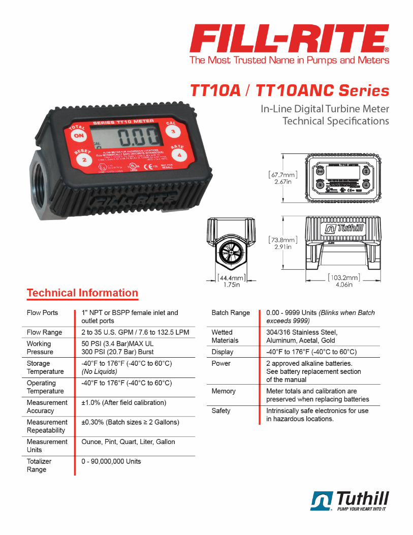
(F) The manner in which the distribution pumps will be labeled to ensure proper use of the test fuel and meet California’s fuel labeling requirement in accordance with California Business and Professions Code, section 13480(a); The distribution pumps for the fuel will be labeled as B99 according to CBP Code. The fuel will be located in a private lot, not available for retail sale. Additionally, the fuel will be controlled by Optimus’ SMARTFuel RFID fuel management system and will only be permitted to be filled in vehicles which are equipped with the appropriate RFID ring tag. The ring tags are affixed to the vehicles and cannot be easily moved between vehicles; this ensures that the fuel will only be used in the B99 fuel tanks of the participating vehicles. Fuel transactions per truck will be logged via electronic pulse meter (see attached Fillrite pulser specification in Appendix C).
(G) The name, address, telephone number, title of the person(s) and the name of the company or organization requesting entry into a Stage 1 pilot program; and Kevin Smyth 6901 Lynn Way, Pittsburgh PA 15208 (412)727-8228x5 Senior Mechanical Engineer Optimus Technologies, Inc.
(H) If different from the information in (G) above, the name, address, telephone number and title of the person(s) and the name of the company or organization responsible for recording and making the information specified above available to the Executive Officer and the location in which such information will be maintained. Same as above.
(I) Chemical and physical properties of the candidate ADF: complete chemical speciation, Chemical Abstract Services (CAS) numbers (if available), density, energy content, vapor pressure, oxidative potential, distillation curve, log Kow (water-octanol partition coefficient), and Henry’s law coefficient.
Fatty Acid Methyl Esters (CAS 67762-26-9) Relative Density: 0.87-0.89 @ 25°C Energy Content (Lower Heating Value): 119,550 Btu/gal Vapor Pressure: <2 mmHg Oxidative Potential: Please refer to the CARB Multimedia Report (attached as Appendix F to this submission), which states in Appendix E: "In conclusion, OEHHA cannot determine with certainty whether replacing PD by BD or BD-PD blends for on-road motor vehicle use will reduce adverse human health impacts attributable to oxidative stress and inflammation from toxic chemicals in diesel-engine emissions. The reduction in carcinogen emissions indicates a reduction in cancer risk from use of BD."
6901 Lynn Way 412.727.8228 Pittsburgh, PA 15208 www.optimustec.com
2

Distillation Curve:
Distillation Curve, Degrees F (Degrees C):
IBP 602.20 F (316.78 C)
10 % recovered 622.80 F (328.22 C)
50 % recovered 630.70 F (332.61 C)
90 % recovered 647.50 F (341.94 C)
End Point 665.20 F (351.78 C)
Recovery, vol % 98.85
Residue, vol % 0.71
Loss, vol % 0.51
Log Kow (Water-Octanol Partition Coefficient): 7.45 Henry’s Law Coefficient: 0.014 atm-cu m/mole
This information was compiled from the following sources:
• The attached SDS of REG-produced biodiesel in Appendix D
• The fifth edition of the Biodiesel Use and Handling guide produced by DOE/NREL (also attached to this submission as Appendix E)
• Log-Kow and Henry’s Law Coefficient Sourced from: https://pubchem.ncbi.nlm.nih.gov/compound/Methyl-oleate#section=LogP
• Distillation Curve provided by results derived from samples analyzed as part of the Diesel National Exchange Program on Cetane Number, Courtesy of the NBB
(J) Environmental information about the ADF: Material Safety Data Sheet(s) (MSDS) for all components of the candidate ADF, production process diagram, identification of potential human health or environmental effects, lifecycle flow diagram (including all stages of the process-raw material extraction, manufacturing, distribution, use and disposal including all intervening transportation steps), and potential release scenarios during production (including by-products), transportation and use. Please refer to the CARB Multimedia Report (attached as Appendix F). The above information can be found as follows:
• Production Process Diagram: Page I-15 • Potential Human Health/Environmental Health Effects: Summarized conclusions on
pages 17-18 • Lifecycle Flow Diagram: Page I-68 • Potential Release Scenarios: Pages 12-17
(K) A statement whether the fuel will be blended with diesel, whether it can be used as a neat fuel, or whether it can be used either way. Biodiesel can be used neat or blended at any concentration with conventional diesel fuel. For the purposes of this pilot program, the fuel will consist of 99% biodiesel meeting the ASTM D6751 standard and 1% CARB Diesel meeting the ASTM D975 standard.
6901 Lynn Way 412.727.8228 Pittsburgh, PA 15208 www.optimustec.com
3


(M con’t) Appendix J includes proprietary emissions testing conducted at WVU CAFEE by Optimus Technologies over the road using a PEMs unit.
Additionally, the studies below are current literature examples of criteria emissions testing completed utilizing biodiesel with NTDEs.
Karavalakis et al., Emissions and Fuel Economy from Two Current Technology Heavy-Duty Trucks Operated on HVO and FAME Blends, SAE Int. J Fuels Lubr., 9(1):2016
Lammert et al., Effect of B20 and Low Aromatic Diesel on Transit Bus NOx emissions Over Driving Cycles with a Range of Kinetic Intensity, SAE Int. J Fuels Lubr., 5(3):2012
Gysel et al., Emissions and Redox Activity of Biodiesel Blends Obtained from Different Feedstocks from a Heavy-Duty Vehicle Equipped with DPF/SCR Aftertreatment and a Heavy-Duty Vehicle without Control Aftertreatment, SAE 2014-01-1400 Published 04/01/2014
McWilliam et al., Emission and Performance Implications of Biodiesel Use in an SCR-equipped Caterpillar C6.6 2010-012157 Published 10/25/2010
Mizushima et al., Effect of Biodiesel on NOx Reduction Performance of Urea-SCR System 2010-01- 2278 Published 10/25/2010
Walkowicz et al., On-Road and In-Laboratory Testing to Demonstrate Effects of ULSD, B20, and B99 on a Retrofit Urea-SCR Aftertreatment System, SAE Int. 2009-01-2733
(N) Attestation that the vehicles to be used in the pilot program are owned by the applicant or the applicant has received written consent from their owners. Please see appendix B for a signed confirmation of the fleet agreement.
(O) The vehicle identification number (VIN) of each vehicle participating in the pilot program, if known. Please find this information in Appendix A.
(P) Affirmative statement that the owner(s) of all vehicles to be used in the applicant’s pilot program are aware of any possible warranty issues that may arise from the use of the candidate ADF or candidate ADF/CARB diesel blend in their engines. Please see appendix B for confirmation of the end user’s awareness of associated risks.
(Q) One of the following: Attachment A: Final Regulation Order Page A-9/A-40 1. A declaration that a fuel standard has been approved for the ADF pursuant to Chapter 14 of the Business and Professions Code (section 13400 et seq.); or if no such standard exists, 2. A copy of the developmental fuel variance application that the applicant has submitted to the California Department of Food and Agriculture pursuant to Business and Professions Code section 13405, proof of its approval, and a declaration that: a. The requirements of Business and Professions Code sections 12001– 13800, other than those pertaining to fuel quality, have been met, and
6901 Lynn Way 412.727.8228 Pittsburgh, PA 15208 www.optimustec.com
5

b. The California Department of Food and Agriculture received a copy of the application required to be submitted under 13 CCR 2293.5. Please see the attached fuel variance letter (Appendix G) and the attached fuel variance application (Appendix H).
(R) Proof that the candidate fuel complies with the U.S. Environmental Protection Agency requirements at 40 Code of Federal Regulations part 79. Biodiesel is a registered fuel under 40 CFR 79. A list of all registered Biodiesel can be found on the EPA’s website. Please find the link below. The fuel used for this program will be a registered fuel from this list.
https://www3.epa.gov/otaq/fuels1/ffars/web-biodiesel.htm#R
(S) It is the responsibility of the applicant to identify any specific portion of the information submitted above as trade secret. Any such trade secret information identified by the applicant shall be treated pursuant to 17 CCR 91000—91022 and the California Public Records Act (Government Code section 6250 et seq.).
Optimus Technologies would request that section L, in addition to appendices A, B, and J remain trade secret.
6901 Lynn Way 412.727.8228 Pittsburgh, PA 15208 www.optimustec.com
6


TO: Allan Morrison, CDFA
FROM: Kevin Smyth, Optimus Technologies Inc.
DATE: 4/2/2020
SUBJECT: Fuel Variance Application
Please find below the submission for a fuel variance for the private fleet use of B99 (1% CARB Diesel,
99% Biodiesel).
Increased use of B99 would provide several benefits to the people of California. B99 has an incredibly
low carbon intensity score, and reduces GHG emissions by an average of 80%. Other benefits of B99
include the reduction of particulate matter and total hydrocarbon tailpipe emissions. Additionally, it is
produced domestically and reduces our dependence on foreign oil. It is the safest alternative fuel to
store and handle. CARB produced a multimedia evaluation in 2015 that stated:
“In general, studies have found environmental benefits associated with biodiesel use as compared to use of CARB diesel fuel. Biodiesel is considered a low
carbon fuel and supports GHG emission reductions. Biodiesel emits less CO, PM, THC,
and air toxics than CARB diesel.” -2015 CARB – Multimedia Report
The fuel will be consumed exclusively by NTDE Medium and Heavy Duty vehicles in
fleet, for the purposes of evaluating the fuel through the ADF regulation, and for
evaluating Optimus Technologies’ Vector System through ARB’s aftermarket parts EO submission
process. Please find the attached document for additional fleet information.
Throughout the duration of the fuel variance, information regarding fuel quality, cost, and availability
will be collected, in addition to the amount of fuel consumed. Also, data pertaining to vehicle fuel
economy, reliability, and tailpipe emissions will be used for the evaluation of the fuel for the ADF
regulation, in addition to the Aftermarket Parts evaluation.
For reporting purposes, Optimus Technologies proposes that quarterly reports including total gallons of
the developmental used and any information concerning impact to vehicle performance or reliability will
be submitted to CDFA. As required by the ARB Stage 1 ADF, the total gallons consumed over the first
year of the variance are not to exceed the energy equivalent of 1 million gallons of CARB diesel.
Optimus Technologies agrees to abide by any request made by the Department pertaining to the
Developmental Engine Fuel Variance Program.
Future activities to support the development of a fuel standard include dynamometer testing for tailpipe
emissions of high blends of biodiesel in NTDE engines. Furthermore, this fleet-use project will serve as a
case study for any impacts on vehicle performance or reliability during on-road use, as well as verifying
the economics and logistics of using B99 as an on-road fuel.
6901 Lynn Way 412.727.8228 Pittsburgh, PA 15208 www.optimustec.com

Additional testing and data collection may be conducted or recorded as requested by CDFA or CARB, for
the fuel variance, ADF Stage 1, or Aftermarket Parts EO submission.
I appreciate you taking the time to evaluate this submission. Please don’t hesitate to reach out with any
questions or concerns.
Best,
Kevin Smyth
6901 Lynn Way 412.727.8228 Pittsburgh, PA 15208 www.optimustec.com

SOUTHWEST RESEARCH INSTITUTE ®
6220 CULEBRA ROAD 78238-5166 • P.O. DRAWER 28510 78228-0510 • SAN ANTONIO, TEXAS, USA • (210) 684-5111 • WWW.SWRI.ORG
POWERTRAIN ENGINEERING DIVISION ISO 9001 Certified Fax (210) 522-3950 ISO 14001 Certified
January 6, 2021
Colin Huwyler Chief Executive Officer Optimus Technologies 6901 Lynn Way Pittsburg, PA 15208
Via email: [email protected] [email protected]
Subject: Test Plan for Section 27156 of the California Vehicle Code for Optimus Technologies
1.0 INTRODUCTION
The Department of Diesel Engine and Emissions Research & Development (DEERD) at Southwest Research Institute (SwRI®) is pleased to provide this test plan to Optimus Technologies. The proposed test plan is submitted for a device evaluation using a protocol specified by the California Air Resources Board (CARB). The protocol is based on transient emission measurement procedures developed by the EPA for emissions regulatory purposes. The CARB protocol allows a 2019 Cummins X15 engine (engine family - KCEXH0912XAW) to be used as the "test bench". The CARB protocol requires the Federal Test Procedure (FTP), Ramped Mode Cycle (RMC) Supplemental Emissions Testing (SET), and the “Not-to-Exceed” (NTE) test according to guidelines specified in the “California Exhaust Emission Standards and Test Procedures for 2004 and Subsequent Model Heavy-Duty Diesel Engines and Vehicles” adopted December 12, 2002 and last amended on April 18, 2019.
2.0 SwRI QUALIFICATIONS
As part of this test plan, SwRI has extensive experience with CARB certification testing, the testing of biofuel blends, and fuel registration testing for the Environmental Protection Agency (EPA). Some of our experience is listed below. A more comprehensive list is available upon request.
• EPA fuel registration of B20 and B100 for the National Biodiesel Board in 1998 • Over twenty years of EPA fuel and fuel additive registration of many different types of
fuels including:

Colin Huwyler Optimus Technologies January 6, 2021 Page 2 of 7
- alternative diesel - Fischer Tropsch - ethanol diesel blends - water/fuel emulsions - vegetable oil - renewable diesel - fuel additives
• More than twenty years of CARB certification testing • Almost 40 years of sampling, characterizing, and measuring toxic air pollutants such as
1,3-butadiene, formaldehyde, acrolein, acetaldehyde, BTEX (benzene, toluene, ethyl benzene, and xylene), and polycyclic aromatic hydrocarbons (PAH)
• Texas Commission for Environmental Quality (TCEQ) Alternative Diesel Fuel Certification testing
SwRI has a 2019 Cummins X15 engine that was used with other testing for CARB. This engine is available for use in this program and meets the following guidelines:
• Test engine certified for use in California (engine family – KCEXH0912XAW) • Test engine accumulated more than 125 hours of normal operation • Test engine tuned to manufacturer specifications • Test engine in good operating condition and baseline emissions typical for the model year
and engine model • System installed according to Optimus Technologies installation instructions • System must be emission tested with a blend containing 20 percent or less of biodiesel
using a CARB diesel and biodiesel (B100) to make the blend • Test engine under the control of SwRI throughout the testing • No maintenance will be performed without prior approval of CARB
3.0 STATEMENT OF WORK
SwRI proposes to test the Optimus Technologies Vector System according to the appropriate CARB test protocol as indicated in a letter from Ms. Kimberly Pryor, Chief, Aftermarket Parts Certification and Audit Branch dated December 22, 2020 (Reference No. A-2020-502). The test cycles will include the FTP, RMC SET, and NTE. The Vector System will be installed in the test cell according to written instructions from Optimus Technologies. The Vector System allows for the diesel engine to operate initially with unheated CARB diesel fuel; and after certain criteria are met, the engine switches over to the heated biodiesel fuel. Regulated exhaust emissions (total hydrocarbons - THC, non-methane hydrocarbons – NMHC which includes the measurement of methane – CH4, carbon monoxide - CO, oxides of nitrogen - NOX, and particulate matter - PM), and carbon dioxide - CO2 will be evaluated for all tests conducted. Tests will be performed according to U.S. Code of Federal Regulations (CFR) Title 40 Part 1065 requirements. Table 1 presents the proposed test plan for the heavy-duty engine test work.

Colin Huwyler Optimus Technologies January 6, 2021 Page 3 of 7
TABLE 1. PROPOSED TEST PLAN FOR HEAVY-DUTY TESTING
STEP DESCRIPTION
1 Perform emission instrument calibrations as required. Calibrate torque meter and check signal conditioning systems. Validate CVS gaseous and particulate sampling systems using propane recovery techniques.
2 Install engine in transient-capable test cell, and check engine condition. Bring engine oil level to "full" using oil specified by the manufacturer.
3
Perform fuel change procedure to CARB reference fuel. Change fuel filters, purge fuel supply, etc. Install the Vector System according to written instructions. Prepare the fuel handling system to operate by bypassing the Vector System or with the Vector System in-use.
4 Repeat Step 1 as necessary. With the Vector System in bypass mode, operate the engine at rated speed and full load for approximately 10-minutes, then power validate engine.
5 Conduct transient “full-throttle” torque map from low- to high-idle and save resulting transient command cycle. (Note: This initial transient command cycle with the CARB reference fuel will be used for all subsequent emission tests in this test plan.) Change the Vector System to the operating position.
6 Run at least one 20-minute practice EPA transient cycle and adjust dynamometer controls to meet statistical requirements for transient cycle operation. Soak the engine overnight for a cold-start test.
7 Run a cold-start and a hot-start transient cycle with a 20 minute soak between each. Collect samples for THC, NMHC, CO, NOX, PM, and CO2 during each cycle.
8 Run an RMC SET as a “prep”, and run an RMC SET with emissions. Collect samples for THC, NMHC, CO, NOX, PM, and CO2 during the second cycle.
9 Run an NTE cycle at the three designated speed/load points. Collect samples for THC, NMHC, CO, NOX, PM, and CO2 during each point.
3.1 FTP
The heavy-duty FTP is described by means of percent of maximum torque and percent of rated speed for each one-second interval over a test cycle of 1199 seconds duration. To generate a transient cycle, an engine's full power curve is obtained from an engine speed below curb idle speed to maximum no-load engine speed. Data from this "power curve," or engine map, are used with the specified speed and load percentages to form a transient cycle. A graphic presentation of the speed and torque commands which constitute a transient cycle is given in Figure 1 for illustration purposes.

Colin Huwyler Optimus Technologies January 6, 2021 Page 4 of 7
FIGURE 1. GRAPHIC REPRESENTATION OF TORQUE AND SPEED COMMANDS FOR THE TRANSIENT CYCLE FOR HEAVY-DUTY ENGINES
In general, a transient test consists of a cold-start transient cycle and a hot-start transient cycle. The same engine command cycle is used in both cases. For the cold-start, the diesel engine is operated over a “prep” cycle, and then allowed to stand overnight in an ambient soak at a temperature between 68°F and 86°F. The cold-start transient cycle begins when the engine is cranked for cold start-up. Upon completion of the cold-start transient cycle, the engine is stopped and allowed to stand for 20 minutes. After this hot-soak period, a hot-start cycle begins with engine cranking. In order to determine how well the engine follows the transient command cycle, engine performance is compared to engine command, and several statistics are computed. These computed statistics must be within tolerances specified in the CFR. In addition to statistical parameters, the cycle work actually produced should be between 5 percent above and 15 percent below the work requested by the command cycle.
3.2 RMC SET
The RMC SET is a 13-mode steady-state engine dynamometer test with linear transitions between modes. This cycle is similar to the European Stationary Cycle (ESC), and it was first introduced by the Environmental Protection Agency (EPA) as part of the 1998 consent decrees with United States heavy-duty engine manufacturers and later included in the 2007 emission standards for heavy-duty engines. The 2007 ramped mode cycle SET is applicable to 2007-2009 heavy-duty engines. While it contains the same operating modes and weightings as the ESC, the order is different and the transition between modes is defined. For 2007-2009 model year engines, manufacturers can use either the 2007 RMC SET or the ESC. For 2010 and later model year

Colin Huwyler Optimus Technologies January 6, 2021 Page 5 of 7
heavy-duty engines, manufacturers must use the 2010 RMC SET. This cycle is similar to the 2007 RMC SET with the exception that the order in which the modes are run is the same as the ESC. For the 2010 model year only, manufacturers can continue to use the 2007 RMC SET as long as it does not adversely affect the ability to demonstrate compliance with emission standards. Table 2 summarizes two versions of the RMC SET cycles. In 2016, the EPA introduced an additional set of weighting factors for the RMC SET test. The two sets of weighting factors are shown in Table 3. Weighting Factor A represents the original weighting factors (identical to those of the ESC), while Weighting Factor B represents an additional set of weighting factors. Weighting factor B were developed to account for the downspeeding trend in heavy-duty engines and are used for testing of engine CO2 emissions for the purpose of EPA Phase 2 greenhouse gas (GHG) emission standards. Weighting factor A continues to be used for the purpose of pollutant (CO, HC, NOx, and PM) emission testing. The engine speeds (A, B, and C) used during the test will be calculated from the following formulas:
A = nlo + 0.25(nhi - nlo)
B = nlo + 0.50(nhi - nlo)
C = nlo + 0.75(nhi - nlo)
3.3 NTE
The NTE should be conducted within the NTE control area. Exhaust emission sampling will be conducted using each of the three test points:
• 50 percent torque at 90 percent rpm • 85 percent torque at 80 percent rpm • 65 percent torque at 70 percent rpm
4.0 SUMMARY
A test plan has been outlined for conducting a test program to obtain transient emissions data from a 2019 Cummins X15 engine using a California reference fuel and with the Vector System using a B20 blend. The emissions data are to be accumulated using the procedure outlined in Table 1 to conduct the emission tests and fuel changes.
It has been a pleasure to prepare this test plan. We hope the items and approach discussed will meet your needs. The DEERD at SwRI looks forward to beginning this project as soon as possible. If you have any questions of a technical nature, please contact E. Robert Fanick by telephone at (210) 522-2653, by FAX at (210) 522-3950, or by e-mail at [email protected].

Colin Huwyler Optimus Technologies January 6, 2021 Page 6 of 7
TABLE 2. RAMPED MODE CYCLE SET
RMC MODE 2007-2009 2010 & LATER
TIME, SEC. SPEED TORQUE, % TIME, SEC. SPEED TORQUE, %
1a Steady-state 170 Warm idle 0 170 Warm idle 0
1b Transition 20 Linear transition Linear transition 20 Linear transition Linear transition
2a Steady-state 170 A 100 173 A 100
2b Transition 20 A Linear transition 20 Linear transition Linear transition
3a Steady-state 102 A 25 219 B 50
3b Transition 20 A Linear transition 20 B Linear transition
4a Steady-state 100 A 75 217 B 75
4b Transition 20 A Linear transition 20 Linear transition Linear transition
5a Steady-state 103 A 50 103 A 50
5b Transition 20 Linear transition Linear transition 20 A Linear transition
6a Steady-state 194 B 100 100 A 75
6b Transition 20 B Linear transition 20 A Linear transition
7a Steady-state 219 B 25 103 A 25
7b Transition 20 B Linear transition 20 Linear transition Linear transition
8a Steady-state 220 B 75 194 B 100
8b Transition 20 B Linear transition 20 B Linear transition
9a Steady-state 219 B 50 218 B 25
9b Transition 20 Linear transition Linear transition 20 Linear transition Linear transition
10a Steady-state 171 C 100 171 C 100
10b Transition 20 C Linear transition 20 C Linear transition
11a Steady-state 102 C 25 102 C 25
11b Transition 20 C Linear transition 20 C Linear transition
12a Steady-state 100 C 75 100 C 75
12b Transition 20 C Linear transition 20 C Linear transition
13a Steady-state 102 C 50 102 C 50
13b Transition 20 Linear transition Linear transition 20 Linear transition Linear transition
14 Steady-state 168 Warm idle 0 168 Warm idle 0

Colin Huwyler Optimus Technologies January 6, 2021 Page 7 of 7
TABLE 3. RMC SET WEIGHTING FACTORS
Mode Engine Speed Load, % Weighting Factor A Weighting Factor B 1 Low idle 0 15 12 2 A 100 8 9 3 B 50 10 10 4 B 75 10 10 5 A 50 5 12 6 A 75 5 12 7 A 25 5 12 8 B 100 9 9 9 B 25 10 9 10 C 100 8 2 11 C 25 5 1 12 C 75 5 1 13 C 50 5 1
Total 100 100 Total A speed 23 45 Total B speed 39 38 Total C speed 23 5
Prepared by: Approved by:
E. Robert Fanick, Principal Scientist Nolan T. Wright, Manager Emission Chemistry Emissions Chemistry Diesel Engine & Emissions R&D Department Diesel Engine & Emissions R&D Department