
F L Y A M Team-Fly - search read.pudn.comread.pudn.com/downloads141/ebook/609009/McGraw-Hill -...
321
TEAMFLY
Transcript of F L Y A M Team-Fly - search read.pudn.comread.pudn.com/downloads141/ebook/609009/McGraw-Hill -...

TEAMFLY
Team-Fly®

OPTICAL SWITCHING AND
NETWORKING HANDBOOK
01_200023_FM/Bates 1/17/01 10:10 AM Page i

McGraw-Hill Telecommunications
Ali Digital Switching SystemsAsh Dynamic Routing in Telecommunications NetworksAzzam High-Speed Cable ModemsAzzam/Ransom Broadband Access TechnologiesBartlett Cable CommunicationsBates Broadband Telecommunications HandbookBayer Computer Telephony DemystifiedBedell Wireless Crash CourseClayton McGraw-Hill Illustrated Telecom Dictionary, 3/eCollins Carrier Grade Voice over IPDavis ATM for Public NetworksGallagher Mobile Telecommunications Networking with IS-41Harte CDMA IS-95Harte Cellular and PCS: The Big PictureHarte Delivering xDSLHarte GMS SuperphonesHeldman Competitive TelecommunicationsLachs Fiber Optics CommunicationsLee Lee’s Essentials of WirelessLee Mobile Cellular Telecommunications, 2/eLee Mobile Communications Engineering, 2/eLouis Telecommunications InternetworkingMacario Cellular Radio, 2/eMuller Bluetooth DemystifiedMuller Desktop Encyclopedia of TelecommunicationsMuller Desktop Encyclopedia of Voice and Data Network-ingMuller Mobile Telecommunications FactbookPattan Satellite-Based Cellular CommunicationsPecar Telecommunications Factbook, 2/eRichharia Satellite Communications Systems, 2/eRoddy Satellite Communications, 3/eRohde/Whitaker Communications Receivers, 3/eRussell Signaling System #7, 3/eRussell Telecommunications Pocket ReferenceRussell Telecommunications Protocols, 2/eShepard Optical Networking DemystifiedShepard Telecommunications ConvergenceSimon Spread Spectrum Communications HandbookSmith LMDSSmith Practical Cellular and PCS DesignSmith Wireless Telecom FAQsSmith/Gervelis Cellular System Design and OptimizationTurin Digital Transmission SystemsWinch Telecommunication Transmission Systems, 2/e
01_200023_FM/Bates 1/17/01 10:10 AM Page ii

OpticalSwitching and
NetworkingHandbook
Regis J. “Bud” Bates
McGraw-HillNew York Chicago San Francisco Lisbon
London Madrid Mexico City Milan New DelhiSan Juan Seoul Singapore Sydney Toronto
01_200023_FM/Bates 1/17/01 10:10 AM Page iii

Copyright © 2001 by The McGraw-Hill Companies. All rights reserved. Manufactured in the United States of America. Except as per-mitted under the United States Copyright Act of 1976, no part of this publication may be reproduced or distributed in any form or byany means, or stored in a database or retrieval system, without the prior written permission of the publisher.
0-07-138288-7
The material in this eBook also appears in the print version of this title: 0-07-137356-X.
All trademarks are trademarks of their respective owners. Rather than put a trademark symbol after every occurrence of a trade-marked name, we use names in an editorial fashion only, and to the benefit of the trademark owner, with no intention of infringe-ment of the trademark. Where such designations appear in this book, they have been printed with initial caps.
McGraw-Hill eBooks are available at special quantity discounts to use as premiums and sales promotions, or for use in corporatetraining programs. For more information, please contact George Hoare, Special Sales, at [email protected] or (212)904-4069.
TERMS OF USEThis is a copyrighted work and The McGraw-Hill Companies, Inc. (“McGraw-Hill”) and its licensors reserve all rights in and to thework. Use of this work is subject to these terms. Except as permitted under the Copyright Act of 1976 and the right to store andretrieve one copy of the work, you may not decompile, disassemble, reverse engineer, reproduce, modify, create derivative worksbased upon, transmit, distribute, disseminate, sell, publish or sublicense the work or any part of it without McGraw-Hill’s prior con-sent. You may use the work for your own noncommercial and personal use; any other use of the work is strictly prohibited. Yourright to use the work may be terminated if you fail to comply with these terms.
THE WORK IS PROVIDED “AS IS”. McGRAW-HILL AND ITS LICENSORS MAKE NO GUARANTEES OR WARRANTIESAS TO THE ACCURACY, ADEQUACY OR COMPLETENESS OF OR RESULTS TO BE OBTAINED FROM USING THEWORK, INCLUDING ANY INFORMATION THAT CAN BE ACCESSED THROUGH THE WORK VIA HYPERLINK OROTHERWISE, AND EXPRESSLY DISCLAIM ANY WARRANTY, EXPRESS OR IMPLIED, INCLUDING BUT NOT LIMITEDTO IMPLIED WARRANTIES OF MERCHANTABILITY OR FITNESS FOR A PARTICULAR PURPOSE. McGraw-Hill and itslicensors do not warrant or guarantee that the functions contained in the work will meet your requirements or that its operation willbe uninterrupted or error free. Neither McGraw-Hill nor its licensors shall be liable to you or anyone else for any inaccuracy, erroror omission, regardless of cause, in the work or for any damages resulting therefrom. McGraw-Hill has no responsibility for the con-tent of any information accessed through the work. Under no circumstances shall McGraw-Hill and/or its licensors be liable for anyindirect, incidental, special, punitive, consequential or similar damages that result from the use of or inability to use the work, evenif any of them has been advised of the possibility of such damages. This limitation of liability shall apply to any claim or cause what-soever whether such claim or cause arises in contract, tort or otherwise.
DOI: 10.1036/0071382887
abc McGraw-Hill

CONTENTS
Preface xi
Acknowledgments xiii
Chapter 1 Introduction to Optical Communications 1
Transmission System Terms 3
History of Optical and Fiber in Telecommunications 8
The Demand for Bandwidth 9
Fiber Justification 13
How It Works 14
Facts about Fiberoptics 15
Fiber Myths 17
Types of Fibers 19
An Application of Fiberoptics 20
Growth in Fiber-Based Systems 22
The Emergence of Wavelength-Division Multiplexing 24
Chapter 2 Basic Fiberoptics Technologies 27
What About the Local Carrier? 32
The Fiber Concept 33
Transmitting the Signal
on the Glass 34
Types of Fiber 37
Fiber Cable Types 38
Benefits of Fiber over Other Forms of Media 44
Bending Cables 45
Sending Light Down the Wires 46
Lasers 48
Fiber Cable Conditions 49
Getting Fiber to Carry the Signal 50
Chapter 3 SONET 53
Background Leading to SONET Development 55
The North American Digital Hierarchy 56
DS-0 56
DS-1 57
DS-3 57
01_200023_FM/Bates 1/17/01 10:10 AM Page v
Copyright 2001 The McGraw-Hill Companies, Inc. Click Here for Terms of Use

Asynchronous Transmission 58
Bit Stuffing 59
SONET: A Means of Synchronizing Digital Signals 60
SONET Line Rates 61
Why Bother Synchronizing? 63
The SONET Frame 64
Overhead 64
Inside the STS-1 Frame 67
SONET Overhead 68
Overhead 69
Line Overhead 69
Path Overhead 70
Virtual Tributaries 70
SONET Multiplexing Functions 71
Concatenation 73
Add-Drop Multiplexing: A SONET Benefit 75
SONET Topologies 76
Point-to-Point 77
Point-to-Multipoint 77
Hub and Spoke 78
Ring 78
Chapter 4 Synchronous Digital Hierarchy 81
Why SDH/SONET 83
Synchronous Communications 84
Plesiochronous 84
Synchronous Digital Hierarchy 86
Data Transmission Rates 87
Some Differences to Note 88
The Multiplexing Scheme 89
Why the Hype? 100
The Model as It Pertains to SDH 102
Chapter 5 Wave-Division Multiplexing and Dense-Wave-DivisionMultiplexing 105
Growing Demands 107
What Is Driving the Demand for Bandwidth? 107
Wave-Division Multiplexing 109
Benefits of Fiber over Other Media 114
Contentsvi
01_200023_FM/Bates 1/17/01 10:10 AM Page vi

Wave-Division Multiplexing 114
Why DWDM? 116
Installing More Fiber Just Does Not Do It! 122
Getting There from Here 123
Chapter 6 Optical Switching Systems and Technologies 125
Optical Switching in the Metropolitan Network 127
Wide-Area Networks 128
Metropolitan Migration 129
The Need for Metropolitan DWDM Networks 133
Dynamic Optical Add-Drop Multiplexing 133
Ring Interconnection 134
Bottlenecks at the Switch 135
Multiple Choices Available 136
Mirror-Mirror on the Wall . . . 136
Lucent Takes to the Waves 140
MEMS Enhance Optical Switching 142
Economical MEMS 143
Scalable Solutions 144
Easy Upgrades 145
Not Everyone Is Convinced 146
Agilent Does Optical Switching Differently 146
Single Big Fabric or Multiple Smaller Fabrics? 146
Bubble Bubble, Who Has the Bubble? 149
Alcatel Blows Bubbles 150
Chapter 7 Optical Networking and Switching Vendors 153
The Growing Demand 155
Caution: Standards Committees at Work 155
Let the Buying Begin 160
Is There an Alternative in the House? 161
Pay as You Grow 163
Bandwidth Demand Driven by Growing Competition 163
New Applications 164
Applications for DWDM 165
If You Cannot Build It, Buy It 165
Building Block of the Photonic Network 166
The Final List 171
Contents vii
01_200023_FM/Bates 1/17/01 10:10 AM Page vii

Chapter 8 High-Speed Applications 185
Add-Drop Multiplexing: A SONET/SDH Application 188
SONET/SDH Topologies 190
Point-to-Point 190
Point-to-Multipoint 193
Hub-and-Spoke 193
Ring 194
Access Methods 195
Alternative Approaches to Multiple Services Delivery 198
What about the Metropolitan-Area Networks? 202
Applications for DWDM 205
Building Block of the Optical Network 206
The Wide-Area Network 211
Chapter 9 Cost Implications and Financial Trending 215
Sometimes It Is the Fiber 217
It Is in the Glass 219
Transparent Optical Networks 222
Opaque Optical Networks 222
DWDM Capabilities 224
Handling the Bandwidth Crunch 226
Optical Cross-Connects 227
Implementing DWDM 229
Costs for the Metropolitan Networks 231
DWDM Application Drivers 232
Future Upgrades 232
Opportunity Costs 233
Faster, Better, Cheaper 234
Chapter 10 The Future of Optical Networking (Where Is It All Heading?) 237
Changes in Infrastructure 239
Enter the Packet-Switching World 242
Legacy Systems 245
Migration Is the Solution 246
DWDM Created the Sizzle 247
So What About Now? 249
QoS a Reality! 253
Contentsviii
01_200023_FM/Bates 1/17/01 10:10 AM Page viii

Another Thought 254
What Then Can We Do? 256
Satisfying the Last Mile 258
Wireless Optical Networking (WON) 260
Final Thoughts 264
Acronyms 267
Glossary 273
Index 291
Contents ix
01_200023_FM/Bates 1/17/01 10:10 AM Page ix

This page intentionally left blank.
TEAMFLY
Team-Fly®

PREFACE
Before you begin to read this book, please take a moment to read theseintroductory comments. The title of the book may be misleading for manypeople:
For the engineering person, this may sound like the bible of optical net-works and switching systems. Not so! This is not an engineering book andwill not dig into the gory details of bits and bytes, ohms and lamdas, andso on. It will help an engineering person to understand the marketplacefor the products and services that will be designed. It will also show youthe application that the optical networks will satisfy. As I said, however,this is not a technical book. Read it for what it is worth. If you want thegory details, other books can meet that need. I would suggest that you logonto McGraw-Hill’s Web site to find the many choices available.
For the financial and business person, the title may have a tendency toscare you away, thinking that it is a technical book. Please persevere andread on. This book was written for you so that you can understand the var-ious developments and challenges to use or invest in the optical networks.I tried to write this with the simplest of terms and with some storyboardsto make concepts more understandable. I also spent a significant amountof time in developing and shaping the business market strategies. If youare an investor or a VC who needs to understand the future demand forthe products, then I have addressed that. If you are a telecommunicationsmanager who is looking for the services from providers, I have addressedthat too!
This is all about the demystification process of the technologies. Thisoptical networking book is being branded as part of a continuing series ofbooks that are geared toward a specific market niche. The Voice and DataCommunications Handbook, the Broadband Telecommunications Hand-book, and the forthcoming Broadband Wireless Handbook will all be apart of a series. These will aid you in understanding the technologieswithout the techno-geek jargon that is so common in our industry. Unfor-tunately, we are a part of a communications industry that has a very dif-ficult time communicating ideas.
I personally hope that this series will make up for that and clear theway for your understanding.
—REGIS J. “BUD” BATES
01_200023_FM/Bates 1/17/01 10:10 AM Page xi
Copyright 2001 The McGraw-Hill Companies, Inc. Click Here for Terms of Use

This page intentionally left blank.

ACKNOWLEDGMENTS
Before proceeding too far with this document, I want to personally expressmy thanks to the two people who are responsible for this book. The firstis the person who is most responsible for this accomplishment, Gabriele,my wife. Gabriele has always been the drive in front of me, providing theencouragement and the support to continue. No matter how much effortwas necessary, she continued to encourage me to keep going. The week-ends and vacation time that I used to work on this book robbed her of ourfree time together. Moreover, Gabriele is also the person who completedthe graphics by taking my raw pictures (drawings and scribbles) and cre-ating some of the best graphics we have produced to date. Her constantsupport, assistance, and encouragement made this book a reality.
The second person who deserves much of the credit is McGraw-Hill’ssenior editor, Steve Chapman. Steve came to me with an idea of creatingthis book and asked me to do what I do best. His roadwork got this bookapproved in record time by the acquisition committees. Steve also gaveme the room to write in my personal style without trying to encroach onthe style, content, or timing. Steve and I have developed a respect for eachother’s ability to produce and make it happen.
Finally, I want to thank all the companies that have produced productsand services that helped me to learn more about the overall concepts ofthe new world of optical communications. There are too many organiza-tions to list here; however, they know who they are.
01_200023_FM/Bates 1/17/01 10:10 AM Page xiii
Copyright 2001 The McGraw-Hill Companies, Inc. Click Here for Terms of Use

This page intentionally left blank.

Introduction to Optical
Communications
CHAPTER 11
Copyright 2001 The McGraw-Hill Companies, Inc. Click Here for Terms of Use

Welcome to this next installment of the telecommunications madesimple writings! When I first started to write in the early 1990s, Iwas overwhelmed with the amount of work necessary to produce thefirst book. That was the original Disaster Recovery Planning forTelecommunications, Data and Networks, and it was a rather shortbook. However, immediately after completing the final edit, I sworenever to write another book. Well, here we are 10 books later, stillsaying the same things, but releasing a new one. This time the topicis fiberoptics, fiber networking, and optical switching for your read-ing enjoyment and understanding. The intent here is to make thetechnology easy to understand while giving you facts and applica-tions in the state of the industry. Similar to the past books, if you arean engineer looking for technical discussions in the goriest detail,this book is not for you. However, if you fall into the following cate-gories, then this is for you:
� Financial analysts trying to understand the cost implications ofa fiberoptic network for investment or funding purposes
� Telecommunications administrator trying to understand whateveryone is all excited about
� Salesperson in a telecommunications company trying to “walkthe walk” and “talk the talk”
� Data processing person trying to get the most bang out of thedata revolution
� Supplier of bandwidth needing to understand what themanufacturers are all saying
� “Newbie” in the industry trying to understand the technologies
What is this all about? I keep being asked to do things in my ownsimple way. I enjoy public speaking, and I enjoy watching peoplelearn. You can tell when they are learning by that expression ontheir face when the revelation of a concept finally becomes clear.Therefore, I undertook this book on optical networking and switch-ing to try to simplify the overall process of what is going on. Too oftenthe vendors and standards bodies are busy writing standards docu-ments or documentation on how equipment works. They know whatthey are talking about, so they assume that the readers in the indus-try also will know what they are saying. Unfortunately, that is not
Chapter 12

true! Probably all of us have picked up a trade magazine and seen afeature article written by some VP of engineering at a local manu-facturer. The article presents several different acronyms and offersseveral opinions about the product or service. Yes, there is merit inthe article, but too often there is so much jargon that readers have atendency to put the article aside. What a sad thing it would be tohave a communications industry that cannot communicate. It is forthis reason that McGraw-Hill keeps asking for help in offering somesemblance of understanding of industry techniques. One hopes thatsuch understanding will result from this book as it has with the pastones.
Transmission System TermsBefore discussing the fiberoptic world, I should at least describesome very basic terms. These will help you to understand the worldof fiber. There are many other ways of describing the use of fiber, butthese definitions will aid in rudimentary understanding.
Amplifier This device increases the power of an electromagneticwave, such as sound or light, without distorting it, as shown in Fig-ure 1-1. Your stereo amplifier takes the weak radio signals from theair and boosts them so that they are strong enough to drive thespeakers. Amplifiers in fiberoptics systems do almost the samething—they brighten the light passing through the fibers.
Coaxial cable Coaxial cable is a high-frequency transmission linethat is used to send telephone and television impulses. The CATVcompanies use a single cable to deliver multiple channels of TV byemploying a multiplexing technique that separates the signals byfrequency. See the representation of coaxial cable in Figure 1-2.
Modulator A modulator is a change agent. This device converts(changes) electrical on/off pulses into sound pulses for voice tele-phone calls. The modulator in a fiberoptic system does the samething, except that it converts the electrical pulses into pulses of light,as shown in Figure 1-3. A modulator-demodulator (called a modem)
3Introduction to Optical Communications

Chapter 14
Figure 1-2Coaxial cableshandle high-frequencytransmissionsespecially for TV.
Modulator
Input of electrical pulses Output of light pulses
Figure 1-3A modulatorconverts theelectrical pulsesinto light pulses.
Amplifier
Signal weakening
Amplifier
Figure 1-1Amplifiers boostweak signals.
converts information from one form and back again, depending onthe direction.
Laser (light amplification by simulated emission of radiation) Alight source created by exciting atoms, causing them to emit light ofa specific wavelength (frequency) in a focused beam. Think of agroup of people who are all trying to lift a very heavy object, one ata time. Nothing happens because they individually have little

strength. However, if they all get together and lift at the same time,their concentrated strength creates the result. Violà! They lift theheavy object. Doing the same thing with light, by exciting a singlelight particle individually, the beam is barely visible. However, if youconcentrate and excite all the light particles at the same time, youcreate a very intense light beam.
Multimode fiber This type of fiber is used for hauling traffic overshort distances, such as within a building. In optical fiber technol-ogy, multimode fiber is optical fiber that is designed to carry lightrays on different paths or modes concurrently, each at a slightly dif-ferent reflection angle within the optical fiber core. Multimode fibertransmission is used for relatively short distances because themodes tend to disperse over longer lengths (this is called modal dis-persion). Multimode fiber has a larger center core than single-modefiber. Figure 1-4 offers a comparison between multimode (thick) andsingle-mode fiber.
5Introduction to Optical Communications
62.5 microncenter core
8.3 microncenter core
multimode fiber single-mode fiber
Figure 1-4Comparison of the fiber types

Receiver A receiver is an electronic device that converts opticalsignals to electrical signals. Your antenna receives radio signals.A fiberoptic receiver—usually an electronics component called adiode—similarly receives light signals.
Single-mode fiber This type of fiber is used typically for long dis-tances. Single-mode fiber is optical fiber that is designed for thetransmission of a single ray or mode of light as a carrier and is usedfor long-distance signal transmission. Single-mode fiber has a muchsmaller core than multimode fiber.
Time-division multiplexing (TDM) A scheme in which numer-ous signals are combined for transmission on a single communica-tions line or channel. Each signal is broken up into many segments,each having very short duration. The circuit that combines signalsat the transmitting end of a communications link is known as a mul-tiplexer. It accepts the input from each individual end user, breakseach signal into segments, and assigns the segments to the compos-ite signal in a rotating, repeating sequence. The composite signalthus contains data from all the end users. At the other end of thelong-distance cable, the individual signals are separated out bymeans of a circuit called a demultiplexer and routed to the properend users. Think of a road system where you have a six-lane high-way. Suddenly you come to a single-lane bridge. Protocol states thatpolitely, each lane will in turn enable one vehicle to cross the bridge.Therefore, each input (lane) grabs the entire bandwidth (the lane)and passes its traffic (the cars) one at a time. This is shown in Fig-ure 1-5 with the single-lane bridge analogy.
Transmitter Just as a radio transmitter sends out radio signals,an optical transmitter—usually a light-emitting diode (LED) or alaser—sends out optical signals.
Wavelength-division multiplexer (WDM) A fiberoptic deviceused to separate signals of different wavelengths carried on one
Chapter 16
TEAMFLY
Team-Fly®

fiber. Imagine two people talking on the phone at the same time, onewith a deep male voice and the other with a high-pitched femalevoice. You can focus on one person or the other by listening for thedeep sounds or the high ones. Similarly, several signals can be sentalong an optical fiber using different frequencies (colors) of light. Atthe receiving end, the WDM “listens” to the different frequencies andseparates the different signals. This is shown in Figure 1-6.
7Introduction to Optical Communications
1
2
3
4
5
6
single-lane bridge
Lane
6
1
12345
Figure 1-5Time-divisionmultiplexingenables each inputto seize the entirebandwidth for ashort duration inrotation.
Blue
Red
Figure 1-6Wave-divisionmultiplexing uses differentwavelengths(frequencies) oflight.

History of Optical and Fiber inTelecommunicationsLet’s take a trip down memory lane and discuss the use of opticalcommunications in the telecommunications industry from its incep-tion to the development of the various types and modes of fiberopticsystems. The beginning of optical communications is rather inter-esting. It has always been a belief that if you want to know wherethings are going, you have to understand where they have been. Alittle history will help.
Optical communications systems date back to the “optical tele-graph” invented by French engineer Claude Chappe in the 1790s. Heused a series of semaphores mounted on towers, with human opera-tors relaying messages from one tower to the next. Of course, inorder for this to work, the people had to be close enough together tovisually see the other messenger’s motions. This was not a great ser-vice for evening transmission and had some problems with weatherconditions (for example, fog, heavy rain, heavy snow, and so on). Thesystem depended on a line-of-sight operation; hence, the towersneeded elevation to extend the coverage (albeit, a limited distancebetween repeaters) and close proximity.
However, the optical telegraph did perform better than hand-carried messages. Alas, by the mid-nineteenth century the systemwas replaced by the electric telegraph, leaving a scattering of “telegraph hills” as its legacy. The use of electrical transmissions wasbetter suited for communications over distances.
In 1880, Alexander Graham Bell patented an optical telephonesystem, called the photophone. His earlier invention, the telephone,was far more practical and widespread. Bell dreamed of sending sig-nals through the air. Unfortunately, the atmosphere did not carrytransmitted light as reliably as wires carried electricity. Light wasused for a few special applications, such as signaling between ships,but otherwise, optical communications did not achieve the expectedresults.
Later, a new technology began to take root that ultimately wouldsolve the problem of optical transmission. It took a long time beforeit was finally adapted and accepted for voice and data communica-
Chapter 18

9Introduction to Optical Communications
tions. This new development relied on “total internal reflection” thatconfines light in a material surrounded by other materials with alower refractive index, such as glass in air. Chronologically, theevents leading up to the use of glass began with several steps, asshown in Table 1-1.
Today, more than 90 percent of long-distance data traffic in theUnited States is transmitted through fiberoptics. More than 15 1/2million miles of fiberoptic cable has been installed already, all of itusing the original design of Maurer, Keck, and Schultz.
Fiberoptics work by using light pulses traveling along glass fibersthat are less than the thickness of a human hair to transmit data.These cables are much smaller than conventional copper wires andare able to transmit data at very high speeds, making them ideal forvideo and audio.
The Demand for BandwidthMeanwhile, telecommunications engineers were seeking ways ofdelivering more transmission bandwidth. Radio and microwave fre-quencies were already in heavy use. Therefore, the engineers lookedto higher frequencies to carry traffic loads, which they expected tocontinue increasing with the growth of television and telephone traf-fic. Telephone companies thought video telephones lurked justaround the corner and would escalate bandwidth demands even fur-ther. In 1964, during the World’s Fair in New York, AT&T introducedan experimental model of the PicturePhone that required a T3 line1
to transmit motion video across a telephone link (Figure 1-7). Theother end of the connection was at Disneyland (in California). Thecommercial version was introduced in 1970 in Pittsburgh. Despiteall the hopes and predictions, the cost and bandwidth demands ofthis device made it impractical. Moreover, the device was bulky andnot user-friendly. However, the seed was planted for the future use ofa video conferencing system that would transmit real-time pictures.
1A T3 is a multiplexed transmission that delivers 44.736 Mbps of information.

Chapter 110
1840s Daniel Collodon and Jacques Babinet showed that light could beguided along jets of water used for fountain displays.
1854 John Tyndall created interest in guided light by displaying lightguided by a jet of water flowing from a tank.
1900s Various inventors realized that bent quartz rods could carry light andpatented them as dental illuminators.
1920s John L. Baird and Clarence W. Hansell patented the idea of usingarrays of hollow pipes or transparent rods to transmit images for tele-vision or facsimile systems.
1930s Heinrich Lamm demonstrated image transmission through a bundle ofoptical fibers. He used his to look inside inaccessible parts of the bodyin a medical application. He also documented that he could transmitan image through a short bundle of fibers. However, the unclad fiberstransmitted the images poorly.
1940s Many doctors used illuminated Plexiglas tongue depressors.
1951 Holger Møller Hansen applied for a Danish patent on fiberoptic imag-ing. The Danish patent office denied his application, based on Bairdand Hansell’s patents.
1954 Abraham van Heel, Harold H. Hopkins, and Narinder Kapanyin sepa-rately announced imaging bundles. None of these people made bundlesthat could carry light very far, but their reports popularized thefiberoptics revolution. The primary innovation was made by van Heel.Early use of fiber was with “bare glass,” with total internal reflectionat a glass-air interface. Van Heel covered a bare fiber with a transpar-ent cladding with a lower refractive index.
1956 The next step was the development of glass-clad fibers by LawrenceCurtiss while working part time on a project to develop an endoscopeto examine the inside of the stomach.
1960 Glass-clad fibers had attenuation of about 1 decibel per meter, whichworked well for medical imaging. This was much too high for use intelecommunications.
1970 Maurer, Keck, and Schultz made the first optical fiber with data losseslow enough for wide use in telecommunications. It is now capable oftransmitting data 65,000� times faster than regular copper wiremethods.
Table 1-1
Timeline forDevelopment ofFiber-BasedSystems

11Introduction to Optical Communications
Figure 1-7The PicturePhonewas introduced by AT&T in 1964(AT&T). (Forcomparison, a 1970s Picture-Phone and a more recent one.)
Serious work on optical communications had to wait for the con-tinuous-wave helium-neon laser. Although air is far more transpar-ent at optical wavelengths than to millimeter waves, researcherssoon found that rain, haze, clouds, and atmospheric turbulence lim-ited the reliability of long-distance atmospheric laser links.
By 1965 it was clear that major technical barriers remained forboth millimeter-wave and laser telecommunications. Millimeterwaveguides had low loss, but only if they were kept perfectlystraight; developers thought the biggest problem was the lack ofadequate repeaters. Optical waveguides were proving to be a prob-lem. Design groups at Bell Telephone Labs were working on a sys-tem of gas lenses to focus laser beams along hollow waveguides forlong-distance telecommunications. However, most of the telecommu-nications industry thought the future belonged to millimeter wave-guides.
Optical fibers had attracted some attention because they wereanalogous in theory to plastic dielectric waveguides used in certainmicrowave applications. In 1961, developers demonstrated the simi-larity by drawing fibers with cores so small they carried light in onlyone waveguide mode. However, virtually everyone considered fiberstoo “lossy” for communications; attenuation of a decibel per meter
Source: PicturephoneSource: AT&T

was fine for looking inside the body but not for long-haul communi-cations. Telecommunications operated over much longer distancesand required loss of no more than 10 or 20 decibels per kilometer.
At the Corning Glass Works (now Corning, Inc.), Robert Maurer,Donald Keck, and Peter Schultz started with fused silica, a materialthat can be made extremely pure but has a high melting point and alow refractive index. They made cylindrical performs by depositingpurified materials from the vapor phase, adding carefully controlledlevels of dopants to make the refractive index of the core slightlyhigher than that of the cladding without raising attenuation dra-matically. In September 1970, they announced that they had madesingle-mode fibers with attenuation at the 633-nanometer helium-neon line below 20 decibels per kilometer.
The Corning breakthrough was among the most dramatic of manydevelopments that opened the door to fiberoptic communications. Inthe same year, Bell Labs and a team at the Ioffe Physical Institute inLeningrad made the first semiconductor diode lasers capable ofemitting a continuous wave at room temperature. Improvementsover time allowed for dramatically less fiber loss, aided both byimproved fabrication methods and by the shift to longer wavelengthswhere fibers have inherently lower attenuation.
Early single-mode fibers had cores several micrometers in diame-ter, and in the early 1970s, this bothered developers. They doubted itwould be possible to achieve the micrometer-scale tolerances neededto couple light efficiently into the tiny cores from light sources or insplices or connectors. Not satisfied with the low bandwidth of step-index multimode fiber, they concentrated on multimode fibers with arefractive index gradient between core and cladding and core diam-eters of 50 or 62.5 microns. The first generation of telephone field tri-als in 1977 used such fibers to transmit light at 850 nanometers.
These first-generation systems could transmit light several kilo-meters without repeaters but were limited by loss of about 2 decibelsper kilometer in the fiber. A second generation soon appeared usingnew lasers, which emitted at 1.3 microns. Fiber attenuation was aslow as 0.5 decibel per kilometer, and pulse dispersion was somewhatlower than at 850 nanometers. Development of hardware for the firsttransatlantic fiber cable showed that single-mode systems were fea-sible, so when deregulation opened the long-distance phone market
Chapter 112

in the early 1980s, the carriers built national backbone systems ofsingle-mode fiber with 1300-nanometer sources. This technology hasspread into other telecommunications applications and remains thestandard for most fiberoptic systems.
However, a new generation of single-mode systems found applica-tion in submarine cables and systems serving large numbers of sub-scribers. They operate at 1.55 microns. Fiber loss is 0.2 to 0.3 decibelper kilometer, enabling even longer repeater spacing. More impor-tantly, erbium-doped optical fibers serve as optical amplifiers at thiswavelength, avoiding the need for electro-optical regenerators.
Submarine cables with optical amplifiers operate at speeds up to5 gigabits per second (Gbps). These can be upgraded from lowerspeeds simply by changing terminal electronics. Optical amplifiersalso are attractive for fiber systems delivering the same signals tomany terminals because the fiber amplifiers can compensate forlosses in dividing the signals among many terminals.
The biggest challenge remaining for fiberoptics is economic.Today,telephone and cable television companies can cost-justify installingfiber links to remote sites serving tens to a few hundred customers.Terminal equipment remains too expensive to justify installing fiberall the way to the home, at least for now. Instead, cable and phonecompanies run twisted-pair wire or coaxial cable from optical net-work units along the side of the road to individual homes. Time willsee how long this lasts, although many people believe that fiber tothe home (FFTH) is already upon us.
Fiber JustificationMany reasons exist for the initial introduction of fiber, but some ofthe strongest reasons are as follows:
Bandwidth compared with copper Taken in bulk, it would take 33 tons of copper to transmit the same amountof information handled by 1/4 pound of optical fiber.
Strength The tinsel strength of the fiber is greater than that of steel.
13Introduction to Optical Communications

Speed of transmission Fiberoptic networks operate atspeeds up to 10 Gbps, as opposed to 1.54 megabits persecond (Mbps) for copper. Soon, a fiberoptic system will beable to transmit the equivalent of an entire encyclopedia ofinformation in 1 second. Fiber can carry information so fastthat you could transmit three television episodes in 1second.
Immunity to electrical and radiofrequencyinterference Fiberoptic cables have a greater resistance toelectromagnetic noise from items such as radios, motors, orother nearby cables. Because optical fibers carry beams oflight, they are free of electrical noise and interference.
Less weight in installation Fiberoptics have a greatercapacity for information, which means that smaller cablescan be used. An optical fiber cable the size of an electricalcord can replace a copper cable hundreds of times thicker.
How It WorksA glass tunnel through which light travels is created. When the light hits the cladding, it interacts with and reflects back into the core. Because of this design, the light can “bend” around curves in the fiber, and this makes it possible for the light to travel greater distances without having to be repeated. This is illustratedin Figure 1-8.
The light that travels along the fiber is made up of a binary codethat pulses “on” and “off” and determines what information a givensignal contains. The advantage of fiber is that these on/off pulses canbe translated to video, computer, or voice data depending on the typeof transmitter and receiver used.
A fiberoptic cable has two parts: the core (center or inside) and acladding (outside covering). These two parts of the fiber worktogether to cause something called total internal reflection, which isthe key to fiberoptics. The light beam is focused on the core of thefiber, and it begins its journey down the fiber. Soon, because of a turnin the fiber or the direction at which the light originally entered the
Chapter 114

fiber, the light reaches the outside edge of the core. Normally, itwould simply exit the fiber at this point, but this is where thecladding helps. When the light hits the cladding (which is made of amaterial selected especially because it reacts differently to light thanthe core material), instead of going on straight, it reflects. This cre-ates a tunnel effect in which the light bounces its way down the fiberuntil it exits at the other end of the fiber.
Facts about FiberopticsEveryone has a story to tell when asked about fiber. Many of themyths and facts get confused and confusing. Thus we should under-stand just why everyone is so excited about the use of fiberoptics.Let’s start with the facts first:
1. Optical fiber will be the backbone of the informationsuperhighway, transporting voice, video, and data to businesses,schools, hospitals, and homes. Demands for information continue toincrease so much that the maximum available transport rates aredoubling approximately every two years. Because of this rapidgrowth, electronic functions in communications networks eventuallywill be replaced by photonic functions, which provide higherinformation-carrying capacity.
15Introduction to Optical Communications
jacket
glass cladding
jacket
glass cladding
glass core
pointlightsource
Source: Corning
Figure 1-8Light travels down the glass.

2. Fiberoptics are needed because coaxial television cables arecapable of carrying more information than copper wire (unshieldedtwisted-pair wire). Computer and telephone companies needsomething with which to compete with the CATV companies. Thisalso means that the fiber wires will allow the telephone companiesto offer newer services. A new service being offered to consumersknown as very-high-bit-rate digital subscriber line (VDSL) willbring telephony, TV, Internet access, and high-speed future servicesto the door. Yet this will depend on fiber to really achieve the result.Currently, the telephone companies are using a hybrid fiber andcoaxial (HFC) service to offer VDSL.
3. Currently, all new undersea cables are made of optical fibers.This is crucial to the economic installation of high-densitytransmission systems. The cost of the fiber as opposed to the cost ofcopper makes the undersea cable more attractive and readilyavailable. Look at the cost reductions in getting a trans-Atlanticcircuit since the introduction of fiber. Costs literally dove down tomore affordable communications for corporate connectivityinternationally.
4. Many believe that 98 percent of copper wire will be replaced byfiberoptic cable, including at the local loop to the residence. Thisbelief is one we can all take to the bank. Copper has manyproblems in distribution and maintenance. Fiber becomes far moreeconomical. Logic, therefore, points to the deployment of more fiberto every facet of communications. Fiberoptic cable installed in placeof copper wire that already requires replacing is less expensive.Because it only needs repeaters to amplify the signals every sixmiles instead of every mile for copper, the cost of installation ismuch less.
5. Optical fiber phone lines cannot be bugged or tapped easily. Ifone were to attempt to tap into the fiber, the cable would be brokenin the process. This would trip alarms on the link and causemaintenance and surveillance personnel to take notice. Moreover,to rejoin the cable is more difficult, eliminating the novice from theprocess of tapping into a fiber system. By breaking into the cable,the light flow is disrupted (Figure 1-9). By splicing the cableimproperly, loss and transmission impairments become highly
Chapter 116
TEAMFLY
Team-Fly®

problematic. Actually, the light’s reflections and refractions can bechanged significantly, causing character changes in the cable.Therefore, only skilled personnel today can splice the cablesproperly.
6. A fiber is thinner than a human hair. Fibers are 8 to 10 micronsor 50 to 62.5 microns thick. One micron (1 �m) is 1/250th thethickness of a human hair. This thickness (thinness) represents theadvantages of the glass itself. It is lighter and easier to handle. It isimmune to the mechanical problems of copper. It carries thousandsof times the information of copper wire.
7. As radio spectrum becomes more scarce and the need for moreinformation-carrying capacity increases, many utility companies arefinding it cost-effective to install fiberoptic communicationsnetworks.
Fiber MythsMany common misconceptions about optical fiber technology slipinto any discussion. Optical fiber, optical systems, optical networks,optical technology—What does this “opto” jargon mean? It meansoptoelectronic technology: the transmission of voice, data, and videousing pulses of light instead of electricity. Because we discussed thefacts earlier, we should now clear up some of the misconceptionsrelated to fiber and consider “the facts” about fiber’s technical meritsand capabilities. The myths include the following:
1. Fiber is the most expensive wiring option. Actually, fiber isexceptionally cost competitive when compared with coaxial cableand copper twisted-pair cable for most applications. Over the longterm, fiber is actually the least expensive option.
When considering fiber, it is important to look at the total picture.Factors to consider when projecting network costs are the life of thenetwork, the life of the system, the need to upgrade the system forfuture capacity requirements, and the possibility of generatingrevenue by leasing reserve capacity to other carriers. Compared
17Introduction to Optical Communications

with copper twisted-pair cable, optical communications systemsexhibit a much lower bit error rate (BER) while operating at muchhigher data rates. As a result, data transmission is both faster andmore reliable over optical fiber systems. In fact, installing extrafiber provides a bigger bang for the installation buck by preventingdisruption and additional expense when it is time to upgrade.Optical fiber is not hardware-dependent, which means that fibersystems can be upgraded as new transmission technologies becomeavailable.
The biggest chunk of new network costs is usually installation, so itmakes sense to take advantage of the opportunity to meettomorrow’s requirements by installing fiber today.
2. Unshielded twisted-pair cable can be used for high-speed dataapplications. When you transmit above 100 Mbps, fiber is the onlymedium that can be used confidently. As a stopgap measure, somehigh-speed copper wire systems are being offered today. However,these systems may require rewiring with special wire, such as aspecially rated version of shielded twisted-pair cable. Even with
Chapter 118
Figure 1-9Breaking the fiberdisrupts the flow of light along the cable.
this special copper wire, questions still remain as to whether thesystem can transmit 100 Mbps over typical distances.
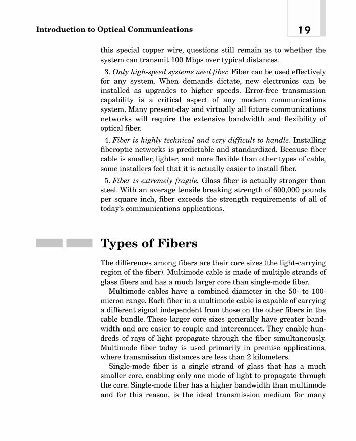
3. Only high-speed systems need fiber. Fiber can be used effectivelyfor any system. When demands dictate, new electronics can beinstalled as upgrades to higher speeds. Error-free transmissioncapability is a critical aspect of any modern communicationssystem. Many present-day and virtually all future communicationsnetworks will require the extensive bandwidth and flexibility ofoptical fiber.
4. Fiber is highly technical and very difficult to handle. Installingfiberoptic networks is predictable and standardized. Because fibercable is smaller, lighter, and more flexible than other types of cable,some installers feel that it is actually easier to install fiber.
5. Fiber is extremely fragile. Glass fiber is actually stronger thansteel. With an average tensile breaking strength of 600,000 poundsper square inch, fiber exceeds the strength requirements of all oftoday’s communications applications.
Types of FibersThe differences among fibers are their core sizes (the light-carryingregion of the fiber). Multimode cable is made of multiple strands ofglass fibers and has a much larger core than single-mode fiber.
Multimode cables have a combined diameter in the 50- to 100-micron range. Each fiber in a multimode cable is capable of carryinga different signal independent from those on the other fibers in thecable bundle. These larger core sizes generally have greater band-width and are easier to couple and interconnect. They enable hun-dreds of rays of light propagate through the fiber simultaneously.Multimode fiber today is used primarily in premise applications,where transmission distances are less than 2 kilometers.
Single-mode fiber is a single strand of glass that has a muchsmaller core, enabling only one mode of light to propagate throughthe core. Single-mode fiber has a higher bandwidth than multimodeand for this reason, is the ideal transmission medium for many
19Introduction to Optical Communications

applications. The standard single-mode fiber core is approximately 8to 10 microns in diameter. Because of its greater information-carryingcapacity, single-mode fiber typically is used for longer distances andhigher-bandwidth applications.
Although it may appear that multimode fibers have higher infor-mation-carrying capacity, this is not the case. Single-mode fibersretain the integrity of each light pulse over a longer distance, whichenables more information to be transmitted. This is why multimodefibers are used for shorter distances and more often in premises atcorporate locations (such as, high-rise offices, campus environments,and so on).
An Application of FiberopticsHow are fiberoptics used in every day life? A basic telephone conver-sation can be used as an analogy for this discussion. In the NorthAmerican telecommunications system, a call is transmitted from oneend through an electric cable (copper) to an encoder, which transmitsa signal through a fiberoptic (glass) cable. It then travels through arepeater, back through the cable, into a decoder and through an elec-tric cable (copper) into the phone line on the other end. This transi-tion is shown in Figure 1-10 for the flow of communications.
The sound waves that your voice generates become waves of elec-tricity in the mouthpiece of your telephone. Rather than electricityflowing through copper wire to the final destination, fiberopticsenables electricity to pass through the encoder, which measures thewaves of electricity 8000 times each second. The encoder then con-verts these waves into on/off pulses of light (operating as invisibleinfrared light). The pulses are digitized, enabling them to be read bythe telephone system. The digitized message is received at thedecoder. The decoder converts the laser light back into electricity.These electrical waves are changed into the sound that you hear onthe phone. This same process works not only for the telephone butalso for other sources that transmit data (such as, computers, televi-sions, and so on).
Chapter 120

21Introduction to Optical Communications
Repeater
Fiber Fiber
TelephoneCompany
AnalogSignal In
Digital Pulse(Electric)
ENCODER
Light Pulse(Photonic)
DECODER
Electrical SignalRepresents Voice
Copper Cable
Twisted-Pair
Analog
Copper Cable
Figure 1-10The flow of a callthrough the NorthAmerican tele-communicationssystem
2This is also called wave-division multiplexing because different signals are multi-plexed at different wavelengths together.
The amount of data that can be carried is directly proportional tothe transmission systems’ coders/decoders used and the equipmentin the middle. The higher the transport rates, the more calls or themore data that can be carried. The fiber systems use combinations offrequency- and time-division multiplexing. Time-division multiplex-ing (TDM) is used when sampling the input from telephones or com-puter terminals. Using this clocking (sampling) rate of 8,000samples per second, multiplexed signals can be received from multi-ple inputs. From there, frequency-division multiplexing (FDM)2 isused to combine the light beams operating at a certain wavelengthon the fibers themselves. This is shown in Figure 1-11, where thecombination of TDM and FDM is illustrated.
As mentioned earlier, AT&T Bell Labs scientists became inter-ested in light wave communication in the mid-1960s, when it became

apparent that light waves had an enormous capacity for carryinginformation and were immune to electrical interference. Advances inlasers, light-emitting diodes, repeaters, connectors, photodetectors,and glass fibers in the following decades—and the realization thatthey could be fabricated and installed as integrated components—led to the installation of the first light-wave system in an operatingtelephone company in 1977.
This installation was the world’s first light-wave system to providea full range of telecommunications services—voice, data, and video-over a public switched network. The system, installed over about 1.5miles under downtown Chicago, used glass fibers that each carriedthe equivalent of 672 voice channels (a T3).
Growth in Fiber-Based SystemsMore than 15.5 million miles of fiber had been installed worldwideby the end of 1997. Construction continues growing at an endlesspace that should reach 30 million miles by the end of 2001. Chinaand the Far East market is expected to grow three times during theperiod of 2000-2003.
The services using fiberoptic systems are provided by all thetelecommunications providers/carriers. The long-distance companies(AT&T, MCI/WorldCom, British Telecom) have been using fiberoptics
Chapter 122
Amplifier
Signal weakening
Amplifier
Figure 1-11The combination of TDM and FDMon fiber

for decades. Many others, such as the competitive local exchange car-riers (CLECs), CATV companies, electric utility companies, and theincumbent local exchange carriers (ILECs),3 are relatively new inthis portion of the industry. The regional Bell operating companies(RBOCs) have a great deal of fiber in place within their major oper-ating cities. They are now looking to expand their capacity ascheaply as possible because of the embedded copper plant that israpidly becoming a liability. The newer carriers (like the CLECs) areplanning to build networks based on new fiberoptics that are signif-icantly less expensive than those used by their competitors. Theirgoal is to enter the market with a sufficiently attractive cost perminute for voice calls and cost per bit for data transmission toattract users to them. The cost per minute has long been the mea-sure of data and voice transmissions.
A T3 operating at nearly 45 Mbps costs from US$80,000 toUS$100,000 per month from the East Coast to West Coast. Thismakes the cost of transmission very reasonably priced when allthings are compared. Let’s look at the overall cost per minute for a45-Mbps link. At US$80,000 per month, this can be priced as shownin Table 1-2 to keep things straight.
One can see the differences by using the T3, for example. However,prior to having the fiber-based networks, the carriers charged muchmore for the service on copper. Using an analogy of those costs, thecosts would be far more dramatic, as shown in Table 1-3 for a copper-based architecture in the past. In this scenario, using a copper cableplant, the cost per T3 from East Coast to West Coast on the carriernetworks varied between $560,000, $280,000, and $175,000 permonth based on variables of length of agreement, cities connected,and so on.
23Introduction to Optical Communications
3 The Bell Systems LECs are more experienced in using fiber since the 1970s and1980s.

Chapter 124
@ $560,000/ @ $280,00/ @ $175,000/
Item Month Month Month
Cost per day with 20-day month $28,000 $14,000 $8,750
Cost per hour with 8-hour day $3,500 $1,750 $1,094
Cost per minute $58.34 $29.17 $18.23
Cost per second $0.972 $0.49 $0.30
Cost per bit $0.000000021 $0.000000012 $0.000000007
Table 1-3
Comparing theCost of Using aCopper-Based T3Access Link
T3 Line East to West Coast Cost per Item
Per month $80,000
Per day based on a 20-workday month $ 4,000
Per hour based on a 8-hour workday $ 500
Per minute at 60 minutes per hour $ 8.33
Per second at 60 seconds per minute $ 0.14
Per bit at 45 million bits per second $ 0.000000003�
Table 1-2
Comparing theCosts of Using a Fiber Link forT3 Access
The Emergence of Wavelength-Division MultiplexingAs early as 1988, synchronous optical networking (SONET) and syn-chronous digital hierarchy (SDH) were the hottest discussion topic interms of the emerging backbone fiber standards of all futuretelecommunications networks. Both SONET and SDH were seen asthe panacea for carriers in developing multiplexing standards andtechniques to reinforce the network. In 1997, wavelength-division

multiplexing (WDM) suddenly became the big-ticket item. Man-agers, designers, and engineers alike saw the benefit that multiplewavelengths could add to the capacity of fiber-based networks. Manycolors of light4 increase the capacity of the installed fiber to 320 Gbpsand in the future 1.6 terabits per second (Tbps)5 and beyond. Theo-retical limits of fiber today are around 30 to 40 Tbps, but with somechanges, in the future we may see 100-Tbps possibilities.
SONET and SDH standards were designed originally for the TDMsystems prevalent in the 1980s. Using TDM, a data stream at ahigher bit rate is generated directly by multiplexing lower-bit-ratechannels. High-capacity TDM systems operate at levels up to OC-192, or 10 Gbps. The problem comes with moving to higher band-width speeds at OC-768 and above. Current TDM equipment hastrouble operating at these higher speeds.
WDM, in contrast, can carry multiple data bit rates, enabling mul-tiple channels to be carried on a single fiber. The technique quite lit-erally uses different colors of light down the same fiber to carrydifferent channels of information, which are then separated out atthe distant end by a receiver that identifies each color. All opticalnetworks employing WDM with add/drop multiplexers and cross-connects permit this. Dense WDM (DWDM) systems multiplex 32 ormore wavelengths in the 1550-nanometer range, increase capacityon existing fiber, and are data-rate-transparent.
DWDM ring systems can be connected with Asynchronous Trans-fer Mode (ATM) switches and Internet Protocol (IP) routers. ATMnetworks are expected to use SONET/SDH physical-layer interfaceswith OC-12 add/drop multiplexers. ATM can carry voice, video,and data communications in the same transport and switchingequipment.
25Introduction to Optical Communications
4Although I refer to many colors of light, the two primary lasers used are red and blue,with variations on the wavelength of each.Variations can be considered like shades ofred and shades of blue.5Terabits per second is trillions of bits per second.

In the future, optical technology and advanced optical switchingtechnologies will emerge that extend the capability of the opticallayer. These technologies will include optical switching for recoveryfrom failures as well as expansion of the add/drop multiplexing func-tion. The first optical cross-connect systems will route a particularwavelength from one fiber route to another without conversion backto an electronic form.
Chapter 126
TEAMFLY
Team-Fly®

Basic Fiberoptics
Technologies
CHAPTER 22
03_200023_CH02/Batesx 1/17/01 8:17 AM Page 27
Copyright 2001 The McGraw-Hill Companies, Inc. Click Here for Terms of Use

As explained in Chapter 1, “Introduction to Optical Communica-tions,” fiberoptics is not new. However, the field has been ignited byseveral new uses and applications of older technologies. The tele-phone companies were deploying the basic fiber systems in theirlocal architectures and then moved into Synchronous Optical Net-working (SONET) architectures in local and metropolitan areas. Wealso learned that the long-distance carriers were moving toward arobust networking strategy using fiber and SONET in support oftheir networks. Corporate users also began migrating to fiber insidethe walls of their office buildings on local area networks (LANs) orcampus area networks (CANs). The issues that inevitably surfacewhen discussing the use of fiber include
� Cost per foot of the fiber as opposed to copper-cable plant
� Cost of the electronics
� Cost of the repeaters and amplifiers
� Difficulty of installation
Each of these issues was, in its own right, a valid concern.The costissues were significant several years ago. However, technologymatures, and mass production begins driving the prices down tomore palatable and financially justifiable levels.
Suppose that we were asked by management to rewire a buildingtoday. The first question we have to satisfy is: How much bandwidthdo we think we are going to need in the backbone of the network, andwhat demands will exist to the desktop? The answer is going to be ascomplex as the question. Several congruent technologies can satisfymost of our day-to-day needs today. However, whether they can meetthe demands for the future becomes the tough part. An example ofthis is the use of copper unshielded twisted-pair wires to the desktop.Clearly, we started out with the use of the different categories of wireto satisfy our immediate needs to the end-user terminal device. Sum-marily, Table 2-1 presents the original design around the categoriesof wire for use in a building infrastructure and the speeds that aresupported. This table is a summary of the systems in place. However,several deviations and methods by which improvements can bemade do exist. The assumptions used in the cable specification werethat the wires would be as follows:
Chapter 228
03_200023_CH02/Batesx 1/17/01 8:17 AM Page 28
� Unshielded twisted pairs of wire (although you can useshielded)
� 100-ohm (100-�) cables
� Solid conductors in the cabling (you can use stranded wires, butsolid conductor is more available)
� 24-gauge wire (24 AWG)
� 100 meters (328 feet)
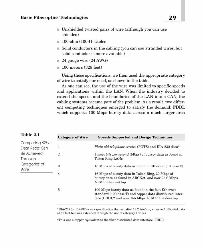
Using these specifications, we then used the appropriate categoryof wire to satisfy our need, as shown in the table.
As one can see, the use of the wire was limited to specific speedsand applications within the LAN. When the industry decided toextend the speeds and the boundaries of the LAN into a CAN, thecabling systems became part of the problem. As a result, two differ-ent competing techniques emerged to satisfy the demand: FDDI,which supports 100-Mbps bursty data across a much larger area
29Basic Fiberoptics Technologies
Category of Wire Speeds Supported and Design Techniques
1 Plain old telephone service (POTS) and EIA-232 data*
2 4 megabits per second (Mbps) of bursty data as found inToken Ring LANs
3 10 Mbps of bursty data as found in Ethernet (10 base T)
4 16 Mbps of bursty data in Token Ring, 20 Mbps ofbursty data as found in ARCNet, and now 25.6 MbpsATM to the desktop
5� 100 Mbps bursty data as found in the fast Ethernetstandard (100 base T) and copper data distributed inter-face (CDDI)† and now 155 Mbps ATM to the desktop
*EIA-232 (or RS-232) was a specification that satisfied 19.2 kilobits per second (Kbps) of dataat 50 feet but was extended through the use of category 1 wires.
†This was a copper equivalent to the fiber distributed data interface (FDDI).
Table 2-1
Comparing WhatData Rates CanBe AchievedThroughCategories ofWire
03_200023_CH02/Batesx 1/17/01 8:17 AM Page 29

using a multimode fiber, and the 100 base F, which is the Fast Eth-ernet standard on multimode fiber in a backbone. Now the 1,000base F standard (Gigabit Ethernet) is supported on multimode orsingle-mode fiber in the campus. This adds a new dimension to theuse of fiber because the speeds are ever-increasing, yet the corporateuser has other issues to handle. The selection of a wiring standard isusually based on a specific point in time. For example, 5 years ago,one may have selected Category 3 wiring as a norm because this wasthe standard for Ethernet cabling at the time. However, in a matterof months, Category 5 wires appeared, causing heartburn for admin-istrators who had installed the older version. In 1996 and 1997, theuse of 100 base T wiring became far more prevalent. This meant thatthe building that was prewired for lower-speed networks was notconducive to supporting the newer high-speed standard. The choiceswere limited:
1. Use only 10 base T on these wires.
2. Rewire the building to support the higher speeds at 100 andnow 1,000 Mbps.
Figure 2-1 shows the growth rates for 100-Mbps Ethernet. Thisfigure shows the percentage of new installations that use the 100-
Chapter 230
Growth of 100 Mbps Ethernet Usage
0% 20% 40% 60% 80%
1996
1997
1998
1999
Figure 2-1Growth of the 100base T standard
03_200023_CH02/Batesx 1/17/01 8:17 AM Page 30

Mbps standards. In newer PCs, 10/100-Mbps network interface cards(NICs) have been installed because of uncertainty as to what the enduser’s wiring supports. This will change over time.
Just as the industry started to accept use of the 100-Mbps stan-dards for Ethernet at the desktop, the next step in the evolutionarrived in 1998. Dubbed the Gigabit Ethernet (1,000 Mbps), the ini-tial standard specified the use of fiber. The industry needed toregroup and develop a new category of wire to support 1,000 Mbps.This appeared in a higher-value (Category 6 or 7) wiring structure.However, the same problem surfaced. If the user wants support forthe higher data rates, then rewiring will be necessary to the stationsthat will use the gigabit speeds. Recognizing this problem, theTelecommunications Industry Association (TIA) and the ElectronicsIndustry Association (EIA) developed work-around specifications soas to use existing in-building wiring (Categories 3 and 5). This is nota specific standard to support the faster data rates. Figure 2-2 illus-trates the expected growth of Gigabit Ethernet in the corporate envi-ronment.
Unfortunately, when the 10-Gbps Ethernet emerges as a standardin the new millennium, the same issues will surface. The wiring inplace will not support the speeds, and some work-around techniqueswill be required. Creative solutions are the mainstream these days.
Fiber in the backbone and to the desktop may well be a bettersolution. Although the cost of the NIC for a workstation is more
31Basic Fiberoptics Technologies
200220012000199919981997
0
500
1000
1500
2000
2500
3000
3500
4000
4500
5000
In M
illion
s $
Figure 2-2Growth of GigabitEthernet
03_200023_CH02/Batesx 1/17/01 8:17 AM Page 31

expensive and the cost of fiber to the desk is going to be higher, theneed to rewire every time a new speed is achieved can be minimized.Over the longer term, the use of fiber to the desk is likely a lessexpensive solution. Unfortunately, local management does not seethis point yet. Therefore, buildings continue to be wired with copperand rewired when speed increases are needed. Single-mode fiber tothe desk will support speeds of up to 10 Gbps today without anywavelength-division multiplexing (WDM). Think of the possibilitieswith WDM.
Figure 2-3 illustrates the growth in capacity of fiberoptics bywavelength and the capacity potential for each of the standards-based services.
What About the Local Carrier?If, on the other hand, a telecommunications carrier decides to buildout infrastructure in the local community, the issue will be less com-plex. Because carriers serve many more users and charge for the
Chapter 232
1975 1980 1985 1990 1995 2000 2005
0.01
0.1
1
10
100
1000
0.8m Wavelength
1.3m
1.3/ 1.5m
1.5m WDM
WDM Systems
Sin
gle
fib
er c
apac
ity
in G
bp
s
Figure 2-3Growth andcapacities offiberoptics overtime (LucentTechnologies)
03_200023_CH02/Batesx 1/17/01 8:17 AM Page 32

usage, the cost issues are far less critical. For years now, carriershave chosen to install fiber whenever possible in their backbone. Theissue they faced was which type of fiber to use: single mode or mul-timode. They have pretty well settled on single mode in all newinstallations.
The Fiber ConceptIt is important for nonengineering professionals to understand thebasics of fiberoptics and the use of multiplexing. However, it is notthe intent of this book to make the reader an engineering wizard.Nevertheless, some technically simplified concepts are required to“talk the talk.” First, it is necessary to understand the basic compo-nents of a fiber-based system. The basic pieces in an optical commu-nications system are shown in Figure 2-4 as a means of explainingthe layout.
The assumption is that at a sender’s end, a serial bit stream in itselectrical form is sent from the sending device to a modulator. Themodulator, as shown in Chapter 1, is the change agent that will con-vert the electrical signal into an optical (photonic) signal. The modu-lator encodes the data for the fibers and sends the data to the laseror a light-emitting diode (LED), which focuses the light as a beam on
33Basic Fiberoptics Technologies
Modulator-Transmitter
AmplifierDemodulator-Receiver
Electrical Input Electrical OutputLight Beams-Photonic
Light Created Light Sensor
GlassFigure 2-4Opticalcommunicationssystem layout
03_200023_CH02/Batesx 1/17/01 8:17 AM Page 33

the fiber. This light beam travels down the glass. Along the way, sev-eral things could happen to the light beam:
1. It could be resisted and lose its signal strength (it gets weaker;weaker means not as bright).
2. It can be dispersed (spread out, making it less intense; spreadcovers a wider area; less focus is a good way to think about it).
Although these two statements sound the same, they are differ-ent.
As the signal is processed, a detector at the far end sees the lightand converts it back into an electrical signal. The signal is amplifiedand given to a demodulator (which has a digital detector) thatdecodes the information back into an electrical bit stream that ispassed to the end terminal. This is not a complicated system. How-ever, the pieces must all work together to produce the desired effectof high-speed communications. At the input, the information must beprocessed fast enough to create the photonic output at a rate of speedconsistent with the fiber. The receiving device must extract the dataequally fast, otherise bottlenecks occur.
Transmitting the Signal on the GlassAs light is transmitted on the fiber, there is a common goal to under-stand: What kind of light are we sending? Light exists at many dif-ferent frequencies (colors). The frequencies (you will hear peoplerefer to this as wavelength) range from visible to invisible light in theultraviolet range. Figure 2-5 lists the frequencies of the spectrum.
When we use these light waves for transmitting in a communica-tions system, we use the infrared spectrum, as shown in Figure 2-5.The light is invisible and can be created with a LED or an infraredlaser. Loss in the glass will be a concern; therefore, infrared is a better choice for transmission. This obviously dispels the myth that you can see the light inside the fiber, because all the communi-cations systems today use invisible light frequencies. Ah, the glory oftechnology!
Chapter 234
03_200023_CH02/Batesx 1/17/01 8:17 AM Page 34

When a short blast (pulse) of light is sent down the glass, it hasthe problems mentioned earlier. The light can be subject to severalimpairments acting on it at the same time. The light beam actuallydegrades quickly. The received light beam will be different from theone that entered the glass initially. It may be weaker (signal loss),smeared out across a wider frequency (time is lengthened), or dis-persed (spreading it across a larger spectrum). Each of these char-acteristics will have an impact on the reception of the information.The impairments are shown in Table 2-2 with a summary of each ofthe major concerns.
Looking at the frequency spectrum, a window of frequencies isused to produce the signal in the normal operating wavelength, as
35Basic Fiberoptics Technologies
VisibleSpectrum
Fiber OpticApplications
Longer Wavelength
Source: Corning
Ultraviolet/400 nm
Violet/455 nm
Blue/490 nm
Green/550 nm
Yellow/580 nm
Orange/620 nmRed/750 nm
Infrared/800 nm850 nm
1300 nm
1550 nm
Increasing Frequency
Multimode, Short Wavelength
Multimode, Single-mode,Long Wavelength
Single-mode,Long Wavelength
Figure 2-5The light spectrumused in fiber(Corning)
03_200023_CH02/Batesx 1/17/01 8:17 AM Page 35

Chapter 236
Impairment Discussion
Attenuation Like an electrical signal moving on copper, the light pulsewill attenuate on the fiber. The signal gets weaker because a certain portion of the light is absorbed by the glass.The actual frequency determines the amount and speed of absorption. Attenuation is stated in the form of decibels (dB).
Dispersion When the pulse is sent down the fiber, it spreads out duringthe transmission. The short pulse becomes longer and joinswith the pulse behind it. This makes it difficult (or impossi-ble) for the receiving equipment to separate the pulses.There are different forms of dispersion, includingMaterial—A range of frequencies is produced by the LEDand laser. The materials used to create the fiber cable usedifferent refractive indices; therefore, each wavelengthmoves at a different speed inside the fiber cable. This meansthat some wavelengths arrive before others and a signalpulse disperses over a broader range. This is also calledsmearing.Waveguide—The center core creates the waveguide (itguides the wave inside the core). The shape and the refrac-tive index inside the core can create the dispersion orspreading of the pulse.Modal—Multimode fiber creates many different modes(paths) for the light to travel down the fiber. The length ofthe path can be different depending on the mode taken,meaning the light beams may take different paths of differ-ing lengths. Portions of the light may arrive out of sequence.This means that the spreading over time causes the fiberreceiver to have to deal with this. The longer the route, thebigger is the problem.
Noise Modal noise is usually associated with multimode fiber. Themismatch of the connectors and the modes in a cable cancause loss of some of the modes. This causes signal loss,which is defined as noise.
Polarization Optical fibers in normal systems are cylindrical and sym-metric. Light traveling on the fiber can change in its polar-ity (positive to negative). At the higher speeds, this maypose problems.
Table 2-2
Problems andImpairmentsFound in FiberSystems
03_200023_CH02/Batesx 1/17/01 8:17 AM Page 36
TEAMFLY
Team-Fly®

described previously.The common wavelengths used in fiber systemstoday are shown in Table 2-3. This table indicates that a transmitteroperating at 850 nanometers will produce a range of frequenciesbetween 800 and 900 nanometers, opening the door for dispersion.The same is true with the other operating frequencies.
Types of FiberAlready the discussion has led to differences in the actual glass.There is fiberoptic, and there is fiberoptic. The characteristics of theglass differ based on materials and manufacturer. Not all fibers arethe same. When first introduced, fiber quality was less than that pro-duced by current technology. Moreover, the chemicals used to pro-duce the glass change the characteristics.The original glass was very“lossy” and barely suited to use in communications systems. The firstfiber systems in telecommunications networks produced losses inthe range of 20 decibels per kilometer. Improvements in the 1980screated glass that reduced the loss to 1 decibel per kilometer. Newerfibers have losses of 0.2 decibels per kilometer or better. The chemi-cals (dopants) added to the glass change the refractive index of theglass, creating more absorption, which is a problem.
37Basic Fiberoptics Technologies
Window of Frequencies Normal Wavelength Used
800-900 nanometers (nm) 850 nm
1250-1350 nm 1310 nm
1500-1600 nm 1550 nm
Table 2-3
Comparison ofFrequencyWindows andOperatingWavelength Used
03_200023_CH02/Batesx 1/17/01 8:17 AM Page 37

Fiber is produced using silicon dioxide (glass). Silica is good for thelower end of the operating frequencies, in the range of 800 to 1,100nanometers. Other forms of fiber use a germanium dioxide mixturein the glass. This fiber type operates better in the range of 1,300 to1,500 nanometers. Thus one can extrapolate that the quality of thevarious glasses is different and that by using different glass compo-sitions, better results can be achieved. The dopants added to theglass mix create higher speeds and less loss.
Fiber Cable Types
The differences between the fibers come down to multimode and sin-gle-mode arrangement. However, stepped-index cables use a differ-ent form of composition to create a fiber cable. The three forms ofcables are
1. Multimode stepped index
2. Multimode graded index
3. Single mode
Multimode Stepped Index Fiber When fiber was first beingused in the communications area, the technology was still develop-ing. Multimode fiber was used as a means of carrying communica-tions signals on glass more reliably. Multimode fiber, as the nameimplies, has multiple paths by which the light can reach the end ofthe fiber. Single-mode fiber, on the other hand, has only one pathover which the light can travel to get to the other end. Using a largepiece (chunk) of pure glass, the developers extruded the fiber intomuch thinner glass strands.
Multimode fibers are thicker glass by today’s standards. Thesemultimode fibers were developed in two different types, step indexand graded index, both operating differently. Figure 2-6 illustrates amultimode fiber using a step index mode. In this case, the glass isvery thick (by today’s standards) at the center core (approximately120 to 400 microns1). The thickness of the glass is crucial to the pas-
Chapter 238
1A micron or micrometer is one-millionth of a meter.
03_200023_CH02/Batesx 1/17/01 8:17 AM Page 38

sage of the light and the path used to get from one end to the other.The step index is the thickest form of fiber, using a core that is 120to 400 microns thick; the light is both refracted and reflected insidethe encased fiber. This is the concept developed in the early days,using total internal reflection. The center core, because of the densityof the glass, refracts the light at different angles. At the same time,an outer cladding on the glass is used to reflect the light back intothe center of fiber. This combination of refraction and reflection ofthe light, along with the density of the glass, causes the light to takedifferent paths (or bounces) to the end of the cable. Different lightbeams inserted into the fiber will take paths of different lengths andtherefore different amounts of time to get to the end of the cable.
A simple analogy to use when thinking about this concept is pad-dleball video games. You have all probably seen video games whereyou have to continue to hit the bouncing ball from paddle to somewall-like barrier. As you bounce the ball, it takes very different pathsto get from the surface of the paddle to the wall and knocks out a fewof the rectangular blocks. However, the return bounce can take avery different route back to the paddle, and vice versa. The ball canbounce very erratically, with several bounces off the sides, before get-ting to the barrier. At other times the ball seems to take a trajectorythat is direct to the barrier. This difference is reflected in the widthof the opening to get from one point to the next. However, if the open-ing is narrowed and the ball can only take a shorter path, such aswhen you break through the barrier, the ball takes a much straighterpath and punches a hole in one spot. By narrowing the openingbetween the paddle and the barrier, the ball moves in a shorter pathto the barrier. Moreover, the bounce back comes much quicker. Actu-ally, the game speeds up considerably, and you have to be preparedwith good hand and eye coordination as the movement speeds.
39Basic Fiberoptics Technologies
Figure 2-6Step indexfiberoptics
03_200023_CH02/Batesx 1/17/01 8:17 AM Page 39

This same concept can be applied to fiber-based networks. Lookingat this in a slightly different perspective, the light will bounce insidethe glass as shown in Figure 2-7. Here, the multiple paths are shownin the geometric bounces that can take place within the glass itself.
Multimode Graded Index Fiber A second form of multimodefiber employs a graded index of the glass, as opposed to the stepindex. Essentially, the grading of the refractive levels of the light ischanged to compensate for refraction and the density of the glass. Inthe step index fiber, modal dispersion (spreading out of the light), asdiscussed earlier, is in part responsible for a reduction in through-put on the fiber. By using a grading of the density of the glass fromthe center core out, the capacity of the fiber can be increased. Sim-ply stated, the more dense the glass, the more refractive is the sur-face of the glass. The more refraction taking place, the longer is thepath. By having a step index, the path in the outer part of the glassis longer than the path in the center of the glass. This means thatlight arrives at different times because the path lengths are differ-ent. Grading the center core to have a higher level of refraction andthe outer parts of the glass to be thinner (and thus less refractive)can use the characteristics of the glass to get approximately thesame length of a wave on the cable and therefore increase the speedof throughput. A graded index fiber is shown in Figure 2-8. The bet-
Chapter 240
Path 1
Pat
h 2
Path 3
Figure 2-7The various pathspossible inmultimode stepindex.
62.5or
50 microns
Figure 2-8Multimode gradedindex fiber.
03_200023_CH02/Batesx 1/17/01 8:17 AM Page 40

ter the grading of the index, the more throughput you can expect.Currently, the two forms of graded index fiber use either a 62.5- ora 50-micron center conductor with a 125-micron outer cladding onthe glass.
Here, an analogy also will help with understanding. We can neu-tralize the effects of the thick and thin glass by creating a differentresistance factor. If the thin glass is in the outer edge and the thickerglass is in the center, the values can be neutralized. This gives us anaverage speed. Think of a racetrack. The summer Olympic gamesuse this effect when they set the stage for foot races. If you are run-ning on the outer edge of a racetrack, the diameter of the oblong thatyou are running is greater than if you are running at the center ofthe track. To compensate for this, the runners are spaced at differentpoints on the track, with the longest length having what appears tobe a lead at the starting block, as shown in Figure 2-9. In reality, allthe runners have to run the same distance; they just have to do it dif-ferently. However, the speed of the runners is what separates theracers, not the lengths of the oblong rings. These have been averaged
41Basic Fiberoptics Technologies
lane 1
Lane 1
lane 2
lane 3
lane 4
Finish Line
Starting positions are jogged toaccommodate distance differences,yielding dual distances to be covered.
Figure 2-9Geometry of thetrack is adjusted toequalize thedistances.
03_200023_CH02/Batesx 1/17/01 8:17 AM Page 41

by the geometry of the track. The same holds true with multimodefibers. By adding some length to the path in the center and shorten-ing the path on the outer edges, the playing field is leveled. This con-cept makes it much easier to manufacture the glass by pulling thethicknesses differently.
Looking inside the fiber, the paths look a bit different from thestepped index format. There is some symmetry to the initial look, butchanges are introduced with the way the light pulses travel down thecable. Figure 2-10 illustrates these changes and the path that is usedto carry the light.
Single-Mode Fiber As fiber became more popular and researchwas stepped up, a newer form of glass was developed. If the glasscould be made very thin and very pure in the center, the light wouldhave no choice but to follow the same path every time. A single path(or single mode) between the two ends enables the developers tospeed up the input because there is no concern about varying pathlengths, as shown in Figure 2-11. The thickness of a single-modefiber today is approximately 8.3 to 10 microns at the center. An outercladding is still present on the edges to reflect the light back into thecenter of the glass. The outer cladding is still approximately 125microns thick. The single-mode fiber is the focus of most of the activ-ity today. Many of the telephone carriers deployed multimode fibersin their networks when they were first introduced. However, over theyears, multimode fiber has given way to single-mode fiber through-out the public carrier networks.
Chapter 242
Figure 2-10The various pathschanged usinggraded indexmultimode fiber
03_200023_CH02/Batesx 1/17/01 8:17 AM Page 42

Let’s try a different analogy this time. Think about a drain pipe. Ifyou have a 6-inch outer diameter drain pipe and you start to dumpwater into the pipe, the water will swish back and forth on the bot-tom of the pipe. As the water works its way to the end of the pipe, itwill have taken a circuitous route to get to there. However, if youdump more water into the pipe, the water may start to experienceresistance and begin a higher motion up the sides of the pipe. Themore flow you put into the pipe (without totally filling it yet), thehigher up the sides the water moves. Now, the back-and-forth motionmay give way to a corkscrew effect swirling down the pipe towardthe opposite end. The path is lengthening to get to the other end asthe corkscrew effect gets more violent. This swirling motion changesthe path. Now suppose you decrease the size of the pipe to 1 inch andput the same amount of water into it. The path is restricted to amuch smaller diameter opening and therefore decreases the size ofthe swirl (making it much tighter). The shorter path means that thewater expels from the opposite end much more quickly. In fact, theappearance is that the water speeds up. It gushes out the oppositeend in a jet stream instead of just flowing out.
We can achieve this same effect with single-mode fibers. Now, asthe light beams are moved into the glass, they move straighter andquicker to the other end. Therefore, we can turn the spigot on faster
43Basic Fiberoptics Technologies
8.3 Microns
Light
8.3 Micron
125 Micronglass
cladding
Figure 2-11Single-mode fiber isso pure and so thinthat light has onlyone path from endto end.
03_200023_CH02/Batesx 1/17/01 8:17 AM Page 43

using a “data pump” to get the flow really moving, increasing theoverall throughput and data rates. The result is faster throughputand shorter distances equaling more data.
Benefits of Fiber over Other Formsof MediaThe benefits of fiber over other forms of media are shown in Table2-4. However, it is important to note that fiber has been usedextensively in the long-distance telecommunications networks andlocal telephone company networks. It is more recent that single-mode fiber has worked its way into end-user networks (LANs andCANs). With single-mode fiber, the speeds are constantly beingupped, and the error performances are being improved continually.The table concentrates on bit error rates (BERs) and the speed ofsuch cabling systems.
Chapter 244
Lower errors BER approximates 10–15, –16 for fiber, whereas copperwill be in the 10–3,–4 for UTP to 10–8 for coaxial cable
Attractive cost Cost per foot for fiber is now approximately $0.20 per foot compared with $0.13 for copper (Category 5+)
Performance Immune from RFI and EMI without extra cost ofshielding on copper
Ease of Ease of installation due to lower weight and thicknessinstallation
Distances Greater distance with fewer repeaters. Now canachieve 30 to 200 miles without repeaters. Copper andradio are limited to less than 30 miles. UTP digitaltransmission systems require repeaters every mile.
Bandwidth Fiber is nearing 1.6 Tbps, copper achieves 100 Mbps,improvements and coax can carry up to 1 Gbps
Capable of carrying Using TDM and WDM, the fiber is both digital andanalog and digital frequency multiplexed, increasing capacity
Table 2-4
Summary ofFiber’sAdvantagesCompared withOther Media
03_200023_CH02/Batesx 1/17/01 8:17 AM Page 44

Bending Cables
As light travels along the fiber, it is reflected from the interfacebetween the core and cladding whenever it strays from the pathstraight down the center. If the fiber is bent during the installation(by design or accidentally), the light only stays in the fiber becausethe pouter cladding reflects it back into the cable. However, totalinternal reflection only works under certain conditions. The angle ofincidence2 must be kept low. If you bend the fiber too much, the lightcan escape. The bending radius is crucial in the installation of fiber.Despite all its strong points, fiber does have some drawbacks, albeitminor. The amount of allowable bending is specific to particularcables because it depends on the difference in refractive indexbetween the cladding and the core. The greater the difference inrefractive index, the more stringent is the allowable bending radius.Figure 2-12 illustrates this bending difference.
45Basic Fiberoptics Technologies
2 The angle of incidence is the angle in which the light hits the cladding.
Cable
Light will bounce
out of the fiber
Cladding
Figure 2-12Light will bounceout of the fiber ifthe bend is tootight.
03_200023_CH02/Batesx 1/17/01 8:17 AM Page 45

Figure 2-13 shows a bending radius that is better designed to keepthe light in the fiber.This enables a smoother flow of the data aroundthe bends when the fiber is installed properly. The amounts of reflec-tion and refraction work better in this case so that the light makes itto the far end.
Sending Light Down the Wires
In order to send data down the fiber, a light source is needed.The twomost common light sources are light-emitting diodes (LEDs) andlasers. LEDs are usually less expensive and are used in many corpo-rate networks, although they are not limited to that application.
Chapter 246
Figure 2-13If the bendingangle is correct,the light movesaround the bend.
03_200023_CH02/Batesx 1/17/01 8:17 AM Page 46
TEAMFLY
Team-Fly®

Because of cost, the LED is a favored device in LANs. Table 2-5 sum-marizes LED characteristics. These devices fit many communica-tions applications.
47Basic Fiberoptics Technologies
Characteristic Description
Low cost LEDs are much less expensive than communicationslasers. This is highly controversial. Communications LEDsand lasers are not much different in structure and arecomparable in manufacturing cost. However, most LEDscannot be used with single-mode fiber, whereas lasers canbe used with either single-mode or multimode fiber.
Relatively wide LEDs output a band of wavelengths instead of a single range of wavelength. This was discussed earlier. The wavelengths frequencies can be reduced by using filters. By filtering the light, a
narrow band of wavelengths can be used. Everyone proba-bly has been exposed to a form of filtering with sun-glasses, sun-blocking agents, or even in photography. Thefilters give the desired effect by blocking specific frequen-cies in the light spectrum.
Low power output The maximum light output of a LED typically is muchlower than a laser. However, a new class of LEDs withhigher output has become available. The regulation ofdevices in production is less severe with LEDs, althoughthings always change.
Digital LEDs cannot produce pulses short enough to be used athigh speeds. LEDs can operate at speeds of up to 622Mbps. Digital modulation is straightforward. The device“turns on” when the voltage is strong enough to power itand turns off when the voltage drops off. This light on,light off can represent the two digital states used in com-munications (0 and 1).
Lenses required A lens is needed to focus the light onto the end of a fiber.LEDs are not suitable for use with single-mode fiberbecause it is too hard to get the light into the narrowopening of the core and focus the light down to the otherend.
Analog too LEDs also can be analog, which is an advantage overlasers. By modulating an analog signal continuously onthe fiber, the information can be carried on the analog car-rier. Most people think that fibers are purely for digitaltransmissions.
Table 2-5
Summary of LEDCharacteristics
03_200023_CH02/Batesx 1/17/01 8:17 AM Page 47

Lasers
Laser is an acronym for light amplification by stimulated emission ofradiation. Without doubt, lasers produce the best kind of light foroptical communications. The laser is the preferred method of lightgeneration for higher-speed communications systems and is usedextensively in long-haul telecommunications networks. Table 2-6summarizes the benefits and operating characteristics of the laser.
Chapter 248
Characteristic Description
Single wavelength This is related to the materials used in the manufacturingprocess to produce the laser. The light is created in paral-lel beams and sent along the transmission path.
Better control Lasers can be modulated (controlled) very precisely.over output
Lenses not The light source is designed for single-mode fiber and required focuses better into the core of the actual glass.
Higher output Lasers can produce relatively high power. They have outpower put capabilities that are as much as 20� times that of
LEDs.
More light source The light is created in parallel beams, so a stronger lightcan be introduced into the fiber. As much as 50 to 80 per-cent of the created light will make it into the fiber. This ismuch greater than with LEDs.
Heat Lasers get hot, so they require additional equipment tokeep them cool; otherwise, they will burn out.
Regulation Rules for using and producing lasers are much moretightly controlled. Specifications also state the minimumdistances and operations where lasers are allowed.
Higher cost The cost of lasers is significantly higher than the cost ofLEDs, and therefore, lasers are not suitable for localizedcommunications networks in a corporate environment.Instead, they are better suited for long-distance networks.
Digital modulation The on and off function is a more direct way to use thefiber in single-mode and laser combinations.
Table 2-6
Summary of LaserCharacteristics
03_200023_CH02/Batesx 1/17/01 8:17 AM Page 48

Fiber Cable Conditions
Fibers themselves are very small, with an outside diameter of 125microns due to the cladding. Although they are also very strongunder tension (greater tensile strength than steel), they break veryeasily when subjected to lateral pressure or any kind of rough han-dling. Therefore, to use fiber in “hostile” communications environ-ments, the fiber needs to be enclosed in a cable. Depending on thelocation and type of installation, fiber cables vary widely in theircharacteristics. They are made to satisfy a specific need. The goal ofusing a cable is to protect the fiber from things that can harm it. Sev-eral risks pose problems for the installers and operators of fiber-based networks, including the following:
Tensile stress Fiber itself is very strong under tension.Stress causes a significant increase in light attenuationand creates a number of other problems. One has to becareful not to stress the cable too much. The fibers also canstretch, causing a change in the reflective and refractiveindices and creating major problems.
Bends Tight bends in the fiber cause signal loss becausethe light escapes through the cladding material. Crimpingthe cable also causes signal loss because the microbendscreate the wrong angle of incidence for the light to bouncedown the fiber. By placing the fibers in a cable, the bendingradius is better maintained because of the additionalmaterials inside the cable (strengthening members andother cladding components).
Physical damage The type of protection used in cablesvaries with the risks posed. Indoor conditions include therisk of rodent damage. The cables are a food supply thatrodents cannot resist. They will chew through the outercladding (and then some), causing damage and loss ofreflective materials (the light will escape from inside thefibers). Rodent damage is not limited to indoor installations.Gophers, rabbits, termites, and fire ants all may eat throughcables.
49Basic Fiberoptics Technologies
03_200023_CH02/Batesx 1/17/01 8:17 AM Page 49

Backhoe fade This risk comes from heavy earth-movingequipment such as backhoes and plows. A major hazard foroutdoor cables is cable-laying machines. In most countries,the cables are laid along rights-of-way. The contractors usedby all the major telecommunications providers cut thecables they are hired to install. Many of the cable cuts arefrom the same contractors that initially laid them in thefirst place.
Damage during installation Cable also must withstandthe stresses of being installed. The installation crews have ajob to do, and they do it. They have little regard for thestresses, tugs, and snags they put in the cable. Their job isto install x amount of cable per day, and they do just that.Consequently, they bend, stretch, and snag/cut the cablingin the process of installing it.
Water Water is the worst enemy of an optical fibersystem. Waterproofing the cable is often more importantthan worrying about some of the other risks. Over time, thefibers begin to degrade because of a chemical reactionbetween the glass and water. The glass can change itsabsorption rate, and this can cause significant loss of signalstrength. The change in the composition of the glass causesit to cloud and changes the refractive and reflectivecharacteristics. Basically, this means that water is a bigproblem. As access holes flood, the water can permeatethrough the outer jacket of fiber cables and cause theseproblems. Water also causes microcracking in the glassfibers, producing light scatter.
Getting Fiber to Carry the Signal
We always try to define the bandwidth of a cable or a radio trans-mission system. This is so because we relate everything to ourtelecommunications discussions. We try to determine the bandwidthof the optical signal.
Chapter 250
03_200023_CH02/Batesx 1/17/01 8:17 AM Page 50

� When transmitting light on a multimode fiber, capacity isquoted as an analog bandwidth measure.
� On single-mode fiber, a modulating signal broadens the spectralwidth (bandwidth) of the carrier signal.
In wavelength-division multiplexing systems, the modulating sig-nal also broadens the spectral width. The bandwidth determinationis not straightforward. A squarewave signal has a fundamental fre-quency of half the bit rate. A 1-Gbps digital signal has a fundamen-tal frequency of 500 MHz operating as a simple sine wave. Asquarewave contains many higher-frequency harmonics at severaltimes the basic frequency. From there, the types of modulation tech-niques used in the telecommunications arena can be analyzed.
Amplitude Modulation (AM) Lasers traditionally have beenvery difficult to modulate with standard amplitude-modulation tech-niques because of the nonlinear response typical of lasers. The majoruse of AM is in CATV and hybrid fiber and coax (HFC) distributionsystems. An analog signal is prepared the same as for the coaxialcable (CATV). Instead of putting it straight onto the cable, it is usedto modulate a laser. At the receiver, the signal is amplified electron-ically and placed onto a section of coaxial cable.
Frequency-Shift Keying (FSK) or Frequency Modulation (FM)It is difficult to modulate the frequency of a laser, and this is one ofthe reasons that FM optical systems are not yet in general use. Somelasers are being introduced that will use an FSK technique. For thisto work, the laser spectral line width has to be considerably nar-rower than the bandwidth of the signal. FSK promises much higherdata rates than the pulse systems currently in use.
Phase-Shift Keying (PSK) or Phase Modulation (PM) Thephase of a laser’s output signal cannot be controlled directly. There-fore, a laser will not produce phase-modulated light. However, a sig-nal can be modulated in phase by placing a modulation device in thelight path between the laser and the fiber. PM has similar advan-tages to FSK.
51Basic Fiberoptics Technologies
03_200023_CH02/Batesx 1/17/01 8:17 AM Page 51

Polarity Modulation or Polarity-Inversion-Shift Keying(PISK) Lasers produce linearly polarized light.A modulation tech-nique might work by changing the light’s polarity. Unfortunately,current fiber changes the polarization of light during transit. There-fore, this may result in a conflict, producing a reversal of the pulsebeing transmitted. This is not available commercially yet.
Directional Transmission Fiber typically is a one-way trans-mission system. Two fibers are used for two-way transmission. Thesize of a single fiber and the number of fibers that can be packed intoa cable make this attractive and the predominant mode of operation.However, a single fiber can carry light in both directions simultane-ously. Devices doing this today use different wavelengths in differ-ent directions.
Many new techniques emerge as fast as the existing ones areinstalled. The market today is ripe for innovation in the use of fiber-based networks and capitalizes on the huge amount of bandwidthavailable.
Current fiberoptic systems produce a single bit per pulse. In thefuture, however, researchers probably will achieve 2, 3, or even 5 bitsper pulse. This, of course, will expand the bandwidth of the fiber byorders of magnitude. With a single bit per pulse, the theoreticalbandwidth (throughput in bits per second) is approximately 3 � 1013
bps (30 Tbps). Even if no improvements are made in the currenttechnology, we can get a 10,000-fold increase using a single fiber overwhat we get today.
This is where the action is taking the industry. The industry islooking toward the following goals:
� To find a way to increase the modulation techniques to get 4, 5,or 6 bits per hertz
� To achieve a higher number of wavelengths on a single fiber
� To optically switch the light instead of having to convert it backto an electrical signal and then into photonic again
� To increase the distances between repeaters so that fiber is lessexpensive to deploy on long-haul circuits
Chapter 252
03_200023_CH02/Batesx 1/17/01 8:17 AM Page 52

SONET
CHAPTER 33
04_200023_CH03/Batesx 1/17/01 9:42 AM Page 53
Copyright 2001 The McGraw-Hill Companies, Inc. Click Here for Terms of Use

Once upon a time, standards were set in North America by the BellSystem, in particular, by AT&T. As the prime carrier for network ser-vices, AT&T set the rules on how the network operated. In 1958, thedesigners at AT&T developed the North American Digital Hierarchyas a means of delivering high-speed digital communications. Thisworked throughout the network because at the time, only oneprovider existed. Because there was no competition, AT&T neededonly to satisfy itself on the operation of the network. Although theNorth American Digital Hierarchy worked, many limitations alsoexisted that curtailed the overall operation of the network. One suchproblem was in the asynchronous nature of many of the transmis-sion systems. The industry needed some critical changes in the net-work to accommodate growth and competition. Moreover, otherchanges were underway. In the late 1960s, competition began toappear in the long-distance network. This competition began tobring additional constraints inside the network to the surface.
Until recently, signal transmission consisted of voice communica-tions, dial-up data communications, and leased lines. These varia-tions all depended on the voice concept of analog communications.However, modern networks must go beyond just a voice networkingstandard and support many different types of signals. Thesedemands required the development of new standards that used syn-chronous transmission capabilities throughout. The services alsorequired openness, including
� Multivendor support
� Multivendor compatibility
� Ease of adding new services when they develop
� Enhancements to operation, administration, maintenance, andprovisioning
� Midspan meeting capabilities
These needs were not being met at the time because no competi-tors shared the services and the backbone networks other than Bell.The changes appeared when the emergence of competition changedthe way the network worked. These requirements led to the devel-opment of the Synchronous Optical Networking (SONET) standardin 1984 and ratification in 1988. SONET is a standard developed by
Chapter 354
04_200023_CH03/Batesx 1/17/01 9:42 AM Page 54

the Exchange Carriers Standards Association (ECSA) for the Amer-ican National Standards Institute (ANSI). This standard defines anoptical telecommunications transport for U.S. telecommunications.The SONET standard provides an extensive set of operational para-meters for optical transmission systems throughout the industry.The North American industry uses the SONET specifications,whereas the rest of the world uses a close “cousin” called the Syn-chronous Digital Hierarchy (SDH), covered in Chapter 4, “Synchro-nous Digital Hierarchy.” Between the two sets of standards, theindustry attempted to define the roles of transport for the telecom-munications providers using optical fibers as the transport medium.
SONET provides more, though. It defines a means to increasethroughput and bandwidth through a set of multiplexing parame-ters. These roles provide certain advantages to the industry, such as
� Reduced equipment requirements in the carriers’ networks
� Enhanced network reliability and availability
� Conditions to define the overhead necessary to facilitatemanaging a network better
� Definitions of multiplexing functions and formats to carry lower-level digital signals (such as DS-1, DS-2, and DS-3)
� Generic standards encouraging interoperability betweendifferent vendors’ products
� A flexible means of addressing current as well as futureapplications and bandwidth usage
SONET defines the optical carrier (OC) levels and electrical equiv-alent rates in synchronous transport signals (STS) for the fiber-basedtransmission hierarchy.
Background Leading to SONETDevelopmentPrior to the development of SONET, the initial fiber-based systemsused in the public switched telephone network (PSTN) were allhighly proprietary. The proprietary items included
55SONET
04_200023_CH03/Batesx 1/17/01 9:42 AM Page 55

� Equipment
� Line coding
� Maintenance
� Provisioning
� Multiplexing
� Administration
The carriers (local and long-distance providers) were frustratedwith the proprietary nature of the industry because of interoper-ability problems, sole-source vendor solutions (which held the carri-ers hostage to one vendor), and cost issues. These carriersapproached the standards committees and demanded that a set ofoperational standards be developed that would allow them to mixand match products from various vendors. In 1984, a task force wasestablished to develop such a standard. The resulting standardbecame SONET.
The North American DigitalHierarchyThe North American Digital Hierarchy is a set of standards estab-lished for the telecommunications industry in North America. Threecountries supported this set of standards initially—the UnitedStates, Canada, and Japan. These three counties adopted sets ofmultiplexing and operating speeds that satisfied the communica-tions networks at the time. The digital signals accepted and adoptedincluded DS-0, DS-1, DS-2,1 and DS-3.
DS-0
When a user makes a call on the PSTN, his or her voice is filtereddown to a 4-kilohertz (kHz) analog signal. It is then sampled at 8,000times per second (the clock rate). The sampling technique creates a
Chapter 356
1DS-2 is defined but not widely used anymore.
04_200023_CH03/Batesx 1/17/01 9:42 AM Page 56
TEAMFLY
Team-Fly®

quantification of the voice in a digital pattern (1s and 0s) using 8 bitsper sample. The result is a 64,000 bits per second (8,000 samples/s�8 bits/sample) stream. This is called DS-0 and is the basis of theNorth American Digital Hierarchy. If higher rates of communicationare needed, a multiplexer is used to merge signals together at thedesired rate.
DS-1
The DS-1 signal is created by multiplexing 24 individual DS-0 digi-tal signals together. Thus, a DS-1 signal is 24 DS-0 signals plus someextra bits for overhead (that is, 8,000), producing the 1.544-megabitper second (Mbps) signal. Each DS-0 signal is assigned its own times-lot on the DS-1. Conceptually, DS-1 is shown in Figure 3-1 (DS-0s).
DS-3
Once the DS-1 is created, 28 DS-1 signals are multiplexed togetherto create a DS-3. This higher-speed communications channel com-bines to create a 44.736-Mbps capacity.Therefore, 672 individual DS-0 signals can be multiplexed together to create a DS-3. A framingformat is used to carry the DS-1 signals on this high-speed channel,as shown in Figure 3-2.
DS-3 is an M13 (pronounced M-one-three) asynchronous trans-mission that uses the M13 Asynchronous Protocol. This means that
57SONET
DS-0
DS-0
DS-0
DS-0 DS-0 DS-0
DS-0
DS-0 DS-0
DS-0
DS-0
DS-0
DS-0
DS-0
DS-0
DS-0
DS-0
DS-0
Figure 3-1A multiplexingoverview of DS-1
04_200023_CH03/Batesx 1/17/01 9:42 AM Page 57

the information, although using synchronous DS-1 signals inside, istransmitted in an asynchronous manner. Asynchronous means thatthe timing of signals carried on the network is random.
Asynchronous TransmissionJust what does it mean to say that a signal is asynchronously trans-mitted, especially that DS-1 signals are synchronous? SONET issynchronous. DS-1 is also synchronous. However, DS-3 is asynchro-nous! Are you confused?
When using a copper- , radio- , or fiber-based network, asynchro-nous refers to digital signals generated on equipment that operatesin one of two conditions—using its own internal clock (timing source)or using separate timing sources (master clocks). Conceptually,again, we have to understand what is happening. DS-1 signals are synchronous unto themselves but not unto others. This meansthat a DS-1 signal is internally timed and operated synchronously.
Chapter 358
DS-1
DS-1 DS-1DS-1
DS-1
DS-1DS-1DS-1
DS-1DS-1
DS-1
DS-1DS-1 DS-1 DS-1
DS-1
DS-1
DS-1Figure 3-2DS-3 mapping andmultiplexing uses28 DS-1 signalsinside.
1 0 111
1
111
0
00
0
000 01
111
1
11 0 0 00
Direction of data flow
Timing Expectedarrival of bit at center
line
Figure 3-3Because some databits arrive laterthan other bits,timing can be aproblem.
04_200023_CH03/Batesx 1/17/01 9:42 AM Page 58

However, the signals are multiplexed one bit at a time into a DS-3signal using a DS-3 multiplexer (the M13). Because each DS-1 signaloperates with its own clock, phase and frequency deviations mayexist among the individual bit streams. This means that the bits canarrive early or late, in contrast to the other inputs. This is shown inFigure 3-3, which presents a conceptual view of the arrival sequence.
Bit StuffingTo compensate for the potential problems and delays in the dataarrival, the equipment must be capable of inserting a bit into anempty slot. This is called bit stuffing. The bits will be inserted intoblank slots so that if a DS-1 line is slow to deliver the necessary bits,substitutes will be put in their place. This creates a scenario wherethe data can be aligned properly. Unfortunately, when we stuff thesebits into a DS-3 data stream, the equipment at the receiving end can-not tell the difference between real data and fake data placed thereto keep the slot occupied.Thus, the multiplexer does not know whereto look for its reference point to find the DS-1 signals inside the DS-3 stream. To get back to the DS-1 signals, the entire DS-3 stream (all28 DS-1 signals) must be demultiplexed.This is time-consuming andexpensive. Figure 3-4 illustrates the bit-stuffing process.
59SONET
1 0 111
1
1110
000
000 0 111
1
11 0 0 00
Direction of data flow
Timing Expectedarrival of bit at center
line
SS S S
Figure 3-4Bits are “stuffed”because the timeslots were empty.
04_200023_CH03/Batesx 1/17/01 9:42 AM Page 59

SONET: A Means of SynchronizingDigital SignalsSONET involves synchronization of the digital signals arriving atthe equipment. Keep in mind that the signals may be introduced inone of three ways. Therefore, it is important to attempt to get every-thing on a common set of clocking mechanisms. In digital transmis-sion, the normal way of synchronizing traffic is to draw a commonclocking reference. In the hierarchy of clocking, systems use a stra-tum clocking architecture. The stratum references in North Americacome in a four-level architecture. These are shown in Table 3-1.
In a set of synchronous signals, the digital transitions in the sig-nals occur at the same rate. A phase difference may occur betweenthe transitions in the two signals, but this would be in specifiedranges and limits. The phase differences can be the result of delay insystems, jitter across the link, or other transmission impairments. Ina synchronous environment, all the clocks are traceable to a commonreference clock (the primary reference clock). Figure 3-5 is a repre-sentation of the various clocks used in the network and the need tocompensate for different transmission paths. This figure assumesthat the different switching systems at the various locations canbuffer the data to overcome jitter or phase problems. Buffers areused to compensate for the different transmission media, the variouspath lengths that can be taken, and the operation of the switchingand multiplexing systems.
Chapter 360
Stratum Reference Location Used Accuracy
1 Primary reference drawn �1 pulse in 10–11
from GPS or the national reference atomic clock
2 Toll offices �1.6 pulses in 10–8
(long distance COs)
3 End offices (local COs) �4.6 pulses in 10–6
4 Customer equipment �32 pulses in 10–6
(multiplexer, channel bank, and so on)
Table 3-1
Summary ofClocking Systems
04_200023_CH03/Batesx 1/17/01 9:42 AM Page 60

If two signals are almost the same, they are said to be plesiochro-nous. Their transitions are close (or almost the same), and variationsare contained within strict limits. The clocking between the two dif-ferent sources, although accurate, may be operating at different rates.
Finally, if two signals are arbitrary in their generation and do notoccur at the same rate, they are said to be asynchronous. The differ-ence between the two clocks is much greater, possibly running froma free-running clock source.
Any one of these signals—synchronous, plesiochronous, or asyn-chronous—may arrive at a SONET multiplexer to be formulated andtransmitted across the network. SONET defines the means of syn-chronizing the traffic for transmission.
SONET Line RatesSONET defines a technique to carry many signals from differentsources and at different capacities through a synchronous opticalhierarchy. The flexibility and robustness of SONET are two of its
61SONET
Transmissionpath
BufferBuffer
Buffer BufferBuffer
Transmissionpath
Transmissionpath
Clock #1
Clock #3
Clock #2Figure 3-5Bufferscompensate fortiming problemsthat occur in thenetwork.
04_200023_CH03/Batesx 1/17/01 9:42 AM Page 61

strongest selling points. Additionally, in the past, many of the high-speed multiplexing arrangements (DS-2 and DS-3) used bit inter-leaving to multiplex the data streams through the multiplexers.SONET uses a byte-interleaved multiplexing format.This is a strongpoint because it keeps the basic DS-0 signal intact throughout thenetwork, making it easier to perform diagnostics and troubleshoot-ing. Byte interleaving simplifies the process and provides better end-to-end management.
The base level of a SONET signal is called the synchronous trans-port signal level 1 (STS-1), operating at 51.84 Mbps. The first step inusing the SONET architecture is to create the STS-1. Other levelsexist in multiples of STS-n to create a full family of transmissionspeeds. The SONET hierarchy is shown in Table 3-2. In SONET, thehigher-level line rates are direct multiples of the OC-1 rate (51.84Mbps), which means that additional stuffing is not necessary in themultiplexing procedures.
Chapter 362
Electrical Optical Speed Capacity
Signal Value
STS-1 OC-1 51.84 Mbps 28 DS-1 or 1 DS-3
STS-3 OC-3 155.520 Mbps 84 DS-1 or 3 DS-3
STS-12 OC-12 622.08 Mbps 336 DS-1 or 12 DS-3
STS-24 OC-24 1.244 Gbps 672 DS-1 or 24 DS-3
STS-48 OC-48 2.488 Gbps 1,344 DS-1 or 48 DS-3
STS-192 OC-192 9.953 Gbps 5,376 DS-1 or 192 DS-3
STS-768* OC-768 40 Gbps 21,504 DS-1 or 768 DS-3
Note: Other rates exist, but these are the most popularly implemented.
*The OC-768 and STS-768 rates are newly defined. As the capacities are increased, the rateswill follow.
Table 3-2
Summary ofElectrical andOptical Rates forSONET
04_200023_CH03/Batesx 1/17/01 9:42 AM Page 62

Why Bother Synchronizing?In the past, transmission systems have been primarily asynchro-nous. Each terminal device in the network was timed independently.In a digital synchronous transmission system, clocking is all-important. Clocking uses a series of pulses to keep the bit rate con-stant and to help recover the 1s and 0s from the data stream.Because these past clocks were timed independently, large varia-tions occurred in the clock rate, making it extremely difficult (if notimpossible) to extract and recover the data. A DS-1 stream operatesat 1.544 Mbps � 150 pulses per second (pps), whereas a DS-3 streamoperates at 44.736 Mbps � 1789 pps. This difference means that oneDS-1 stream may be transmitting at up to 300 pps more or less thananother (assuming that one DS-1 signal is at -150 pps and the otheris at �150 pps). The differences can make it difficult to determinethe actual data across a common receiver.
Earlier we discussed the asynchronous method of multiplexing aDS-3 stream. We saw that bit stuffing was used. Therefore, themethod of synchronously multiplexing in the SONET architectureprovides for better efficiency and problem resolution. Using SONET,the average frequency of all the clocks will be the same. Every clockcan be traced to a common reference, which is highly reliable andstable. Bit stuffing can be eliminated in the preparation of the STS-1 signal, and therefore, the lower speed signals are more readilyaccessible. The benefits outweigh the possible overhead associatedwith the SONET multiplexing scheme. In SONET, the hierarchy ofclocking follows the master-slave clocking architecture. Higher-level(stratum 1) clocks will feed the timing across the network to lower-level devices. Any jitter, phase shifts, or drifting by the clocks can beaccommodated through the use of pointers in the SONET overhead.The internal clock in a SONET multiplexer also may draw its timingfrom a building-integrated timing system (BITS) used by switchingsystems and other devices. This terminal will then serve as the mas-ter for other SONET nodes downstream, providing timing on its out-going signal. The receiving SONET equipment will act in a slavemode (loop timing) with their internal clocks timed by the incomingsignal. The standard specifies that SONET equipment must be able
63SONET
04_200023_CH03/Batesx 1/17/01 9:42 AM Page 63

to derive its timing at stratum 3 or higher. Figure 3-6 is a referencedrawing of the clocking hierarchy used for the network and SONETshowing the way the timing is passed across the network.
The SONET FrameSONET also defines a frame format in which to produce the basicrate of 51.84 Mbps (STS-1). Each addition to the multiplexing ratesis a multiple of STS-1. The basic format consists of a frame that is 80bytes (columns) wide and 9 bytes high (rows). The basic STS-1 signalis then applied into this 810-byte frame. The frame is shown in Fig-ure 3-7. The frame will occur 8,000 times per second. If we do themath on this, we have
810 bytes � 8 bits/byte � 8000 frames/s = 51.84 Mbps
OverheadFrom the 810-byte frame, overhead is enabled in several ways tofacilitate operations, administration, maintenance, and provisioning(OAM&P) services. The first part of the overhead is defined as thetransport overhead. The transport overhead uses the first three
Chapter 364
StratumLevel 1 Master Clock
MasterToll
OfficeStratumLevel 2
StratumLevel 3
# 4 ESS orDMS 100/200
Digital CrossConnect
# 5 ESS orDMS 100
StratumLevel 4 Channel Bank
Multiplexer
Terminates Clock
Customer PremisesEquipment
Figure 3-6Clocking is passeddown the networkfrom the masterclock to the endoffice.
04_200023_CH03/Batesx 1/17/01 9:42 AM Page 64

65SONET
90 Columns
9
Rows
Figure 3-7The SONET frame
columns and all nine rows. This creates 27 bytes of transport over-head. As shown in Figure 3-8, the transport overhead is divided intotwo pieces. The first three columns and the first three rows (9 bytes)are used for section overhead. The remaining six rows in the firstthree columns (18 bytes) are used for line overhead.
Section=3X3
Line3X6=18
TransportO/H= 3X9= 27 SONET OC-1 Frame
Figure 3-8The transportoverhead is dividedinto section andline overhead.
04_200023_CH03/Batesx 1/17/01 9:42 AM Page 65

The remaining 87 columns and 9 rows (783 bytes) are designatedas the synchronous payload envelope (SPE). Inside the SPE, an addi-tional one column nine rows high (9 bytes) is set aside for path over-head. This is shown in Figure 3-9. After the path overhead is setaside, the resulting payload is 774 bytes. In these 774 bytes, the ser-vices are then mapped into the frame. The STS-1 payload can carrythe following:
� 1 DS-3
� 7 DS-2s
� 21 E-1s
� 28 DS-1s
Combinations of these payloads are also allowable. Two columnsare reserved as fixed stuff columns; these are columns 30 and 59.The remaining 756 bytes carry the actual payload.
Chapter 366
SPE: 87x 9 = 783 bytes
Figure 3-9The SPE
04_200023_CH03/Batesx 1/17/01 9:42 AM Page 66
TEAMFLY
Team-Fly®

Inside the STS-1 FrameThe SPE can begin anywhere inside the STS-1 envelope. Normally,it begins in one STS-1 frame and ends there. However, it may beginin one STS-1 frame and end in another. The STS payload pointercontained inside the transport overhead points to the beginning byteof the SPE. The possibilities, then, are that the frame can carry alocked payload or a floating payload. Floating in this regard refers tothe payload floating between two frames. The overhead associatedwith SONET is designed to let the receiver know where to look for itspayload and extract the information at a starting point. A floatingframe is shown in Figure 3-10.
67SONET
POH
POH
TransportO/H
Figure 3-10A floating payloadinside two frames
04_200023_CH03/Batesx 1/17/01 9:42 AM Page 67

SONET OverheadSONET provides significant overhead, enabling simpler multiplex-ing techniques and improved OAM&P operations. The next sectionexamines overhead in greater detail so as to provide a better under-standing of why so much time and energy is dedicated to overheadfunctions.
Figure 3-11 shows the architecture of the SONET link as definedby ECSA and ANSI. In this reference, the link architecture is brokendown into three parts:
Section The section is defined as the portion of the linkbetween two repeater functions or between a repeater and apiece of line-terminating equipment. Sufficient overhead isallowed to detect and troubleshoot errors on the link betweenthese two points (STE).
Line The line overhead provides sufficient information todetect and troubleshoot problems between two pieces of line-terminating equipment (LTE).
Path The path overhead provides sufficient overhead to detect and troubleshoot problems between the end-to-end piecesof path-terminating equipment (PTE).
Chapter 368
Section Section Section
Line
Path
Figure 3-11SONET linkarchitecture
04_200023_CH03/Batesx 1/17/01 9:42 AM Page 68

OverheadThe overhead is shown in Figure 3-12. This overhead contains 9bytes of information that is accessed, generated, and processed bythe section-terminating equipment. It supports functions such as
� Performance monitoring
� A local orderwire
� Data communications channels for OAM&P messages
� Framing information
Line Overhead
The line overhead used between two pieces of LTE provides forOAM&P functions.This is more extensive than the section overhead.
69SONET
A1J0/Z0A2
B1 E1 F1
D1 D2 D3
H1 H2 H3
B2 K 1 K 2
D4 D5 D6
D7D8
D9
D10 D11 D12
S1 Z2 E2
G 1
Z 5
Z 4
Z3
H4
F2
C 2
B 3
J1Figure 3-12SONET overhead
04_200023_CH03/Batesx 1/17/01 9:42 AM Page 69

Path Overhead
The final piece of overhead is the path overhead contained inside theSPE. Path overhead contains 9 bytes of information starting at thefirst byte of the STS SPE. The path overhead provides for communi-cation between two pieces of PTE. The PTE is where the actual mul-tiplexing and demultiplexing functions take place as the services aremapped into the SONET frame. The functions supported by the pathoverhead are as follows:
� Performance monitoring of the STS SPE
� Signal labeling of the individually mapped payloads
� Path status
� Path trace
Virtual TributariesSONET is more than the STS frame. It also defines the sub-STSlevels of payload that can be carried. The STS-1 payload can be sub-divided into virtual tributaries (VTs), synchronous signals to trans-port lower-speed signals. The normal sizes defined by SONET areshown Table 3-3.
Chapter 370
VT Bit Rate Equivalent DS-n Level Required Bytes
(rows � columns)
1.5 1.728 Mbps DS-1 27 (9 � 3)
2 2.304 Mbps E-1 36 (9 � 4)
3 3.456 Mbps DS-1C 54 (9 � 6)
6 6.912 Mbps DS-2 108 (9 � 12)
Table 3-3
The Values of theVirtual Tributaries(VTs) Defined forSONET
04_200023_CH03/Batesx 1/17/01 9:42 AM Page 70

71SONET
VT1.5VT1.5
VT 1.5
VT1.5
Figure 3-13VT1.5s are stillvisible in thepayload of aSONET STS-1signal.
The SONET VT1.5 signal carries a 1.544-Mbps DS-1 signal pluspath overhead. This forms a 1.728-Mbps digital signal. In Figure 3-13, the VT1.5 signals are inserted into the STS payload area. It iseasy to see that the VT1.5 signals are still visible within the STS-1payload area.
SONET Multiplexing FunctionsSONET can accommodate several different signal sizes within theSTS-1 (49.536 Mbps) payload. SONET then multiplexes together theindividual STS-1 signals to form larger signals for transport acrossa fiber medium. SONET also has the ability to carry larger signalsthan the STS-1 payload through a process called concatenation.
The primary principles of the SONET multiplexers are as follows:
� Mapping the tributaries into the STS-n frame
� Aligning the information by using the pointer information todetermine where the first byte of the tributary is located
04_200023_CH03/Batesx 1/17/01 9:42 AM Page 71

� Multiplexing lower-order signals to higher-order signals
� Stuffing of bits necessary to handle the various lower-speedasynchronous channels and filling up the spare bits to keepeverything in alignment.
The SONET equipment provides these functions. SONET cancarry very large payloads, as we have seen in the hierarchy of thedata speeds. Up to now, we have seen the primary mapping and lay-out of an STS-1 (OC-1). SONET equipment can add the value neces-sary to protect investments by either lower- or higher-ratemultiplexing. If one looks at an OC-3, for example, the multiplexerwill produce a larger STS frame. In this case, as shown in Figure 3-14, the frame is three times larger, or 270 bytes (columns) wide and9 rows high, for a total of 2,430 bytes. Note from this figure that theoverhead for the STS-n is located in the beginning of the frame,whereas the path overhead (POH) is located at the start of each pay-load.
When multiplexing the data rates together, there may be a multi-stage multiplexing function from the individual OC-1 to an OC-3and OC-12, and so on. Figure 3-15 is a graphic representation of the
Chapter 372
H1
D1
B1
A1 A2 J0/Z0 A1 A2A1 A2
F1E1 B1 F1E1 B1 F1E1
D2 D3 D1 D2 D3 D1 D2 D3
H2 H3 H1 H2 H3 H1 H2 H3
B2 K 1 K 2 B2K 1 K 2 B2
K 1 K 2
D4 D5 D6 D4 D5 D6 D4 D5 D6
D7 D8 D9 D7 D8 D9D7 D8 D9
D10 D11 D12 D10 D11 D12 D10 D11 D12
S1 Z2 E2 Z1 Z2 E2 E2Z2Z1
270 Bytes
POH
J1
B3
C2
G1
F2
H4
Z3
Z4
Z5
STS-1 number 2
STS-1number 3
STS-1number 1
J0/Z0 J0/Z0
Figure 3-14The STS-3 (OC-3)frame
04_200023_CH03/Batesx 1/17/01 9:42 AM Page 72

multiplexing function from an STS-1 to an STS-3 and then to anSTS-9. This interleaving is what SONET is designed to perform.
Another alternative to this multistep process is to use a singlemultiplexer to handle an STS-12 output with 12 individual STS-1signals inserted directly into it, as shown in Figure 3-16. This single-stage interleaving process directly byte-interleaves the n STS-1 sig-nals into the STS-12 signal shown. However, the numbers can vary,but the outcome is the same; it is a matter of equipment selectionand processing.
ConcatenationConcatenation provides SONET with the flexibility to carry digitalsignals that are larger than the payload described earlier (49.536Mbps). A designator of a concatenated signal occurs when a small cappears after the number of the STS-n (that is, STS-3c). The c indi-
73SONET
1
8
7
6
5
4
3
2
9
STS-3 Number 1
STS-3 Number 3
STS-3 Number 2 STS-9 Number 1
ST
S-1
sS
TS
-1s
ST
S-1
s
Figure 3-15The multiplexingfunction of SONET
04_200023_CH03/Batesx 1/17/01 9:42 AM Page 73

Chapter 374
STS-12
1
3
2
ST
S-1
s
6
5
4
ST
S-1
s
8
7
9
ST
S-1
s
11
10
12
ST
S-1
s
Figure 3-16Single-stepinterleaving into ahigher-speedmultiplexer.
cates that the payload is concatenated, not multiplexed, into threedifferent payloads. This means that a normal STS-3 carries threeseparate STS-1 signals inside, as shown in Figure 3-14. However, ina concatenated state, the total payload is one super rate multiplexedsignal at 155.52 Mbps instead of three smaller ones at 51.84 Mbpseach. This is shown in Figure 3-17.
04_200023_CH03/Batesx 1/17/01 9:42 AM Page 74

Add-Drop Multiplexing: A SONETBenefitAnother major benefit of the SONET specification is the ability toperform add-drop multiplexing. Even though network elements arecompatible at the OC-n level, they may still differ from vendor tovendor. SONET does not attempt to restrict all vendors to providinga single product, nor does it require that they produce one of everytype out there. One vendor may offer an add-drop multiplexer withaccess to the DS-1 level only, whereas another may offer access toDS-1 and DS-3 rates. The benefit of an add-drop multiplexer on awide-area network (WAN) is to drop (demultiplex) only those por-tions of the optical stream required for a location and let the restpass through without the demultiplexing process. It would beextremely inefficient to have to demultiplex an entire OC-12 stream,for example, only to drop out one DS-1. The ability to extract onlywhat is necessary helps to prevent errors, loss of data, and otherdelays inherent to older technologies. The add-drop multiplexermakes this attractive for carriers to use in rural areas, where theymay bundle many lower-speed communications channels onto a sin-gle OC-1 or OC-3 to carry the information back to the central metro-politan area. Moreover, beyond just dropping a digital signal out of ahigher-speed OC-n, the carrier can fill in what has been vacated (forexample, if a DS-1 is dropped off along the optical path, a new DS-1can be multiplexed back into the OC-3 in its place). This enables thecarriers considerable flexibility. Figure 3-18 shows an add-drop mul-tiplexer. Here, portions of the bandwidth can be dropped off and
75SONET
Payload is one contiguous piece
Path
Overhead
Overhead for an STS-3c
Figure 3-17An OC-3cconcatenated
04_200023_CH03/Batesx 1/17/01 9:42 AM Page 75

additional new signals can be added in place of the data streamdropped out of the higher-speed signal. A single-stage add-drop mul-tiplexing function can multiplex various inputs into an OC-n signal.At an add-drop site, only those signals which need to be accessed aredropped and inserted. The remaining traffic continues through thenetwork switching system without requiring special processing.
SONET TopologiesSeveral different topologies can be used in a SONET networkemploying various multiplexers. These include the normal topologiesmost networks have become accustomed to over the years, such as
� Point-to-point
� Point-to-multipoint
� Hub and spoke
� Ring
The variations enable more flexibility for SONET in the WANsbuilt by the carriers and now becoming the method of choice at manylarge organizations. With each of the topologies, larger organizationsare finding the benefits of installing highly reliable interoperableequipment at private network interfaces and access points to publicnetworks.
Chapter 376
DSI
DS1
OC-1 OC-1 OC-1
Figure 3-18Add-dropmultiplexing with SONET
04_200023_CH03/Batesx 1/17/01 9:42 AM Page 76
TEAMFLY
Team-Fly®

Point-to-Point
The SONET multiplexer, the entry-level PTE for an organization [orthe equipment installed by the local exchange carrier (LEC) at thecustomer’s premises to access the network], acts as a concentratordevice for the multiple lower-speed communications channels suchas DS-1 and DS-3. In its simplest form, two devices are connectedwith an optical fiber (with any repeaters as necessary) as a point-to-point circuit. As the entry-level point into SONET architecture, theinputs and outputs are identical. In this environment, the networkcan act as a stand-alone environment and not have to interface withthe public switched networks. Figure 3-19 illustrates the point-to-point multiplexing arrangement.
Point-to-Multipoint
The next step is to consider the point-to-multipoint arrangement.This will use a form of add-drop multiplexing to drop circuits offalong the way. In a large corporate network spanning the country (orany subset), a single high-speed link may be employed. The SONETadd-drop multiplexer (ADM) is used for the task, dropping circuitsout without demultiplexing the entire high-speed signal. In Figure 3-20, the ADM is installed between two far-end locations so that signals can be added or dropped off as necessary. This is a bettersolution than renting three different circuits between points AB, AC,and BC, which adds to the complexity and cost. By using a circuitfrom A to B to C with ADMs, the service usually can be accommo-dated more efficiently.
77SONET
OC-N
OC-N
OC-N
OC-N
Figure 3-19Point-to-pointservice with SONET
04_200023_CH03/Batesx 1/17/01 9:42 AM Page 77
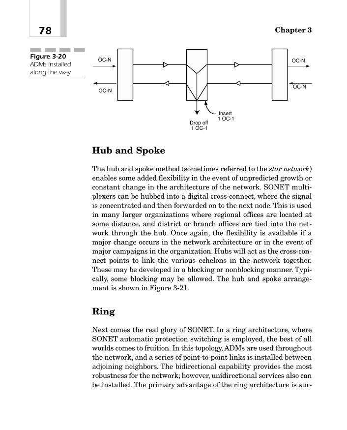
Hub and Spoke
The hub and spoke method (sometimes referred to the star network)enables some added flexibility in the event of unpredicted growth orconstant change in the architecture of the network. SONET multi-plexers can be hubbed into a digital cross-connect, where the signalis concentrated and then forwarded on to the next node. This is usedin many larger organizations where regional offices are located atsome distance, and district or branch offices are tied into the net-work through the hub. Once again, the flexibility is available if amajor change occurs in the network architecture or in the event ofmajor campaigns in the organization. Hubs will act as the cross-con-nect points to link the various echelons in the network together.These may be developed in a blocking or nonblocking manner. Typi-cally, some blocking may be allowed. The hub and spoke arrange-ment is shown in Figure 3-21.
Ring
Next comes the real glory of SONET. In a ring architecture, whereSONET automatic protection switching is employed, the best of allworlds comes to fruition. In this topology, ADMs are used throughoutthe network, and a series of point-to-point links is installed betweenadjoining neighbors. The bidirectional capability provides the mostrobustness for the network; however, unidirectional services also canbe installed. The primary advantage of the ring architecture is sur-
Chapter 378
OC-N
OC-N
OC-N
OC-N
Insert1 OC-1
Drop off1 OC-1
Figure 3-20ADMs installedalong the way
04_200023_CH03/Batesx 1/17/01 9:42 AM Page 78

vivability in the event of a cable cut or a failure in a network node.The multiplexers have sufficient intelligence to reroute or reversedirection in the event of a failure. If more than one fiber link isinstalled, the systems could use alternate paths, but they mustrecover in milliseconds (which APS on SONET is designed to do).Figure 3-22 shows the ring topology with dual fibers running (bidi-rectional service) between the ADMs.
79SONET
ADM ADM
Figure 3-22Ring architecture of SONETmultiplexers
OC-3
OC-1
OC-1
OC-1
OC-1
OC-1
OC-1
Figure 3-21Hub and spoke in a SONETmultiplexernetwork
04_200023_CH03/Batesx 1/17/01 9:42 AM Page 79

This page intentionally left blank.

SynchronousDigital
Hierarchy
CHAPTER 44
05_200023_CH04/Batesx 1/17/01 8:18 AM Page 81
Copyright 2001 The McGraw-Hill Companies, Inc. Click Here for Terms of Use

Chapter 482
As discussed in Chapter 3, Synchronous Optical Networking(SONET) is the high-speed optical-based architecture for carriersand users alike. This optical-based networking strategy was devel-oped in North America by the American National Standards Insti-tute (ANSI). While the ANSI committees were working on SONET,though, another movement was underway. In Europe, the standardscommittees also were wrestling with the logical replacement to thePlesiochronous Digital Hierarchy (PDH), which is an asynchronousmultiplexing plan to create high-speed communications channels.The Europeans came up with a separate multiplexing hierarchycalled Synchronous Digital Hierarchy (SDH) in support of theSONET standards.
Ever since the standards bodies approved the recommendationsfor the SDH (and SONET), the services have been used effectively toimprove and revolutionize the industry. Significant cost efficienciesand performance improvements have been shown. SDH provides ameans for the rest of the world to use the capabilities of fiber-basedtransport systems and multiplexing architectures to improve on theolder PDH, which was inefficient and expensive. The PDH evolved inresponse to the demand for plain old telephone services (POTS) andwas not ideally suited to promote the efficient use of bandwidth andhigh-speed services.
Digital networks continue to expand in complexity and penetra-tion within the carriers’ networks, now moving closer to the con-sumers’ premises. High-speed communications prior to theformulation of SDH in 1990 operated at speeds of up to 139.364megabits per second (Mbps). However, the carriers implementedcoaxial and radio-based systems operating at 140 to 565 Mbps. Thenetworks were severely constrained due to the high cost of the trans-mission medium (coaxial cable especially). The multiplexing ratesused plesiochronous rates, which led to the European PDH.
After the development of fiber and the enhancements of inte-grated circuitry, the newer transmission speeds and complex net-working architectures became realistic. In Europe, the evolution anddeployment of Integrated Services Digital Networks (ISDN) also ledto proliferation of the Broad Band ISDN (B-ISDN) standards, whichenable a simple multiplexing technique. In the United States, thebreakup of Bell Telephone prompted the local carriers to look for
05_200023_CH04/Batesx 1/17/01 8:18 AM Page 82

83Synchronous Digital Hierarchy
interoperability and improvements in network management becauseof proliferation of the number of carriers providing long-distance services.
The International Telecommunications Union-TelecommunicationsStandardization Sector (ITU-TS) agreed that something had to bedone to improve and standardize the multiplexing and interoper-ability while at the same time taking advantage of the higher capac-ity of optical fiber. The older bit interleaving of multiplexers shouldbe replaced by byte interleaving to provide for better network man-agement. The new standard appeared as SONET in the North Amer-icas, drafted by BellCore.1 Later this same standard developed intothe SDH/SONET standard as approved by the ITU. AlthoughSONET and SDH were drafted initially in support of fiber, radio-based systems supporting the same multiplexing rates also becameavailable.
Why SDH/SONETMany reasons explain why SONET and SDH were necessary. Theprimary reason was that previous technology (PDH) was limited inmany ways, such as
� U.S. and European systems had little in common in theirmapping and multiplexing systems. Therefore, expensivetranslators were required for trans-Atlantic traffic on leasedlines.
� “Standard” equipment from different vendors in the samecountry was incompatible. Everyone produced a proprietarysolution that worked with his or her own equipment.
� Systems did not offer self-checking of equipment and networkcomponents. Expensive manual checks were required, andextraordinary repair systems were the norm.
� No standard for high-bandwidth links existed. Everythingmaintained the proprietary approach. This created havoc in theindustry and needed to be improved.
1The BellCore name has since been changed to TelCordia Technologies.
05_200023_CH04/Batesx 1/17/01 8:18 AM Page 83

Chapter 484
� Not all the multiplexing systems were synchronous. In theUnited States, anything above DS-1 bandwidth wasasynchronously multiplexed, timed, and mapped.
Synchronous CommunicationsWhat does synchronous mean anyway? Why is it so important to thetelecommunications industry? The easiest way to describe the needfor synchronization is that the “bits” from one telephone call arealways in the same location inside a digital transmission frame suchas a DS-1. In the United States, telephone calls using digital trans-mission systems create a DS-0. The DS-0 signals are multiplexed 24per DS-1 channel. DS-1 lines are synchronously timed and mapped;therefore, it is easy to remove or insert a call. Finding the locationcreates an easy add-drop multiplexing arrangement.
PlesiochronousPlesiochronous means “almost synchronous.” Variations occur on thetiming of the line, so bits are stuffed into the frames as padding. Thedigital bits (1s and 0s) vary slightly in their specific location withinthe frame, creating jitter. This occurs on a frame-to-frame basis, cre-ating ill timing and requiring some other actions to make everythingbear some semblance of timing. An example seen in the precedingchapter with the multiplexing of a DS-3 stream occurred when
� Four DS-1 lines were bit-interleaved and multiplexed togetherto create a DS-2.
� Seven DS-2 lines were bit-interleaved and multiplexed to createa DS-3.
� We needed to isolate a particular call from a DS-3 stream, andthe entire DS-3 stream had to be demultiplexed to the DS-1level, where we could then extract the individual DS-0 signals.
05_200023_CH04/Batesx 1/17/01 8:18 AM Page 84

85Synchronous Digital Hierarchy
� It became apparent that very expensive equipment was neededat every central office to demultiplex and multiplex high-speedlines across the backbone networks.
Consequently, the standards committees (both ANSI and the ITU)began working on solutions to these multiplexing problems. The ulti-mate attempt was to develop a synchronous transmission systemthat could replace the plesiochronous transmission systems.
Table 4-1 presents a summary and comparison of worldwidespeeds and hierarchical arrangements. This table brings the differ-ences to light when you compare the speeds and multiplexed chan-nels combined.
In 1986, the Consultative Committee of International Telegraphyand Telephony (CCITT)2 published a standard set of transmissionrates for SDH. The SDH standards finally emerged in 1992. Theseare filed under the following standards:
� G.707
� G.708
� G.709
Hierarchical North American European Japanese International
Level DS-n CEPT-n Level Rules
0 64 64 64 64
1 1,544 2,048 1,544 2,048
2 6,312 8,448 6,312 6,312
3 44,736 34,368 32,064 44,736
4 274,176 139,264 97,728 139,264
5 564,992 397,200 564,992
Table 4-1
Comparing theSpeed Rates forVarious Levels ofthe DigitalHierarchy [inkilobits persecond, (kbps)]
2CCITT is now called the ITU-TS
05_200023_CH04/Batesx 1/17/01 8:18 AM Page 85

Chapter 486
Using the same fiber, a synchronous network is able to increasethe available bandwidth while reducing the amount of equipment inthe network. Moreover, the provisioning of SDH for sophisticatednetwork management introduces much more flexibility into theoverall networking strategies for the carriers.
Synchronous Digital HierarchyAs synchronous equipment was rolled into the network, the full ben-efits became more apparent. The carriers experienced significantcost reductions and avoidances, less hardware, and increased effi-ciencies in multiplexing of the various rates established by the ITU.However, other benefits required less spares to be maintained in thenetwork. Additional benefits were had by the use of the SDH stan-dard multiplexing formats, which could encapsulate the PDH multi-plexed signals inside the SDH transport. This protects the carriers’investments and prevents the use of forklift technology. In fact, SDHoffered the network operators the ability to future-proof their net-works, allowing them to offer metropolitan area network (MAN),wide-area network (WAN), and B-ISDN services on a single platform.
The SDH forms a multiplexing rate based on the STM-n frameformat. STM stands for synchronous transmission module. TheSTM-n general frame format works as follows: Similar to theSONET OC-1 (albeit larger), the basic STM-1 frame consists of
270 columns � 9 rows � 2430 octets
9 columns � 9 rows � 81 octets section overhead
The remaining 2349 octets create the payload. Higher-rate framesare derived from multiples of STM-1 according to the value of n. Thestandard STM-1 frame is shown in Figure 4-1. This is similar but dif-ferent from the frame in an OC-3 stream.
05_200023_CH04/Batesx 1/17/01 8:18 AM Page 86
TEAMFLY
Team-Fly®

87Synchronous Digital Hierarchy
9 ro
ws
SectionOverhead STM-N Payload
261xN bytes
270xN bytes
9xN bytes
Figure 4-1The STM-1 frameformats
Data Transmission RatesIn the standards, a number of transmission rates are defined orpossibly based on multiplexing rates. Not all rates are availablecommercially; however, the rates are there in case a new rate isneeded. Similar to the SONET standards, SDH defines the syn-chronous transport signal level n (STS-n) and the SDH level n(SDH-n). These define the electrical rate of multiplexing and theoptical rate of multiplexing, both working at the appropriate rate ofspeed necessary to map and multiplex the higher rates of speed.The typical rates of speed and the appropriate STS and STM ratesare shown in Table 4-2.
Only three of the hierarchical levels are actually defined in thestandard and are available commercially: STM-1, STM-4, and STM-16. Other rates will become available as needed. As the multiplexingoccurs and the overhead is subtracted from the payload, the actualthroughput is shown in Table 4-3. This table reflects the aggregatesof throughput in the three commercially available STM payloads.
05_200023_CH04/Batesx 1/17/01 8:18 AM Page 87

Chapter 488
Some Differences to NoteMany of the actual rates in use are defined under the initial capaci-ties of SONET in the CCITT standards. The original SDH standarddefined the transport of 1.5, 2, 6, 34, 45, and 140 Mbps within thetransmission rate of 155.52 Mbps (STM-1). SDH was intended tocarry the SONET rates; however, the European manufacturers andcarriers carry only the European Telecommunication StandardsInstitute (ETSI)-defined PDH rates of 2, 34, and 140 Mbps (the E-2specification was deleted in the specification). SDH really turns outto be more than just a set of multiplexing speeds and transport rates.It is also a network node interface (NNI) defined by the ITU-TSS forworldwide use that is partially compatible with the ANSI SONET
STM Level Data Rate Actual Payload
1 155.52 Mbps 150.112 Mbps
4 622.08 Mbps 601.344 Mbps
16 2.4883 Gbps 2.40537 Gbps
Table 4-3
SDH PayloadCompositions forHierarchical Rates
Electrical Rate Optical Rate Speed
STS-1 STM-0 51.84 Mbps
STS-3 STM-1 155.52 Mbps
STS-9 STM-3 466.56 Mbps
STS-12 STM-4 622.08 Mbps
STS-18 STM-6 933.12 Mbps
STS-24 STM-8 1.244 Gbps
STS-36 STM-12 1.866 Gbps
STS-48 STM-16 2.488 Gbps
Table 4-2
Comparison ofSTS and STMRates
05_200023_CH04/Batesx 1/17/01 8:18 AM Page 88

89Synchronous Digital Hierarchy
specification. Further, it is one of two options for the user-to-networkinterface (UNI) to support the B-ISDN.
The Multiplexing SchemeWhen trying to understand the SDH architecture, it is important toremember that the North Americans have always done things oneway and the Europeans (actually the rest of the world) have donethings a different way. The two entities never seem to become harmo-nized. As a result, the way the mapping and multiplexing werearranged differs from the way the standards and multiplexing tech-niques work in the North American communities (ANSI and SONET).The language differs from what is used in SONET specifications.
As the framing and formatting begins with the STM-1 frame,using the equivalent of the OC-3 specifications, the language beginsto shift in a simple yet confusing manner. The STM-1 frame is shownin Figure 4-2 again, but with a few differences. First, the frame doesconsist of 270 columns and 9 rows, creating a frame of 2430 bytes.Second, there will be 8,000 frames per second (the frame time is 125 � = micro(s). This creates an overall throughput of 155.52 Mbps,the same as SONET.
AU-4 Pointer
Repeatersection
overhead
Multiplexersection
overhead
270 Columns9 Columns
9 ro
ws
3 ro
ws
5 ro
ws
1 row
261 Columns
125 � sec.
Figure 4-2Size of the STM-1frame
05_200023_CH04/Batesx 1/17/01 8:18 AM Page 89

Chapter 490
As the data are prepared for placement in the frame, several dif-ferent modes of transport are available. At the input, the data flowinto a container with a size designation. For example, C11 is theequivalent of a T-1 transport mechanism at 1.544 Mbps. C12 willcarry the E-1 transport mechanism at 2.048 Mbps. Another trans-port is C2, which is the equivalent of a DS-2 operating at 6.312Mbps.
Each of these container levels is then input into a virtual con-tainer (VC level n). In Figure 4-3, the inputs flow into the basic con-tainer and then are mapped into the VC. This may sound verysimilar to the SONET virtual tributary (VT). SDH defines a numberof containers, each corresponding to an existing plesiochronous rate.The information from a PDH signal is mapped into the relevant con-tainer. This is done in a manner similarly to the bit-stuffing proce-dure used in conventional PDH multiplexers. Each container hassome overhead and control information contained in it, called pathoverhead (POH). The bytes associated with the POH enable the car-
T2
E1
T1
C2
C12
C11
VC2
VC12
VC11
TU 2
TU 12
TU 11
Figure 4-3The VCs arecreated.
05_200023_CH04/Batesx 1/17/01 8:18 AM Page 90

91Synchronous Digital Hierarchy
riers to perform end-to-end monitoring and provisioning for perfor-mance rates. The container and the POH combined together formthe VC.
Next, the VCs are mapped and multiplexed within the frame intoa tributary unit level n. Our example will now complete the inputfrom a container to a VC to a tributary unit. The levels are basicallythe same designation as shown in Table 4-4. The T-1, E-1, and T-2lines can be mapped and multiplexed into VCs that provide the for-mat needed within SDH. The containers are then aligned with thetiming of the system to create a tributary unit (TU).
Four T-1s (TU11), three E-1s (TU12), or one T-2 (TU2) can be mul-tiplexed into a TU group 2, as shown in Figure 4-4. The architecturebegins this way at the entry levels of the SDH.
The next step in the process is to develop a higher level of multi-plexing. Here, the TUs or TU groups are multiplexed into a higherlevel. Let’s think of this as the T-1/T-2 and T-3 architecture in NorthAmerica. Seven TU group 2s are multiplexed into a TU group 3. Thisis a T-3 operating at the �45-Mbps rate of speed. The alternative tothis is to take one T-3 and place that into a TU group 3.This is shownin Figure 4-5, where seven of the TU group 2s (TUG2) or one TUgroup 3 is multiplexed into a TU group 3 (TUG3) and then carriedinto the system as an administrative unit (AU) group 3.
To make this even larger, the next step is to continue the multi-plexing process. Therefore, three of the TUG3s or one E-4 mappedinto a C4 are then multiplexed into the next higher level in the hier-archy called a virtual container 4 (VC4). This is shown in Figure 4-6.
Equivalent Rate Input Mapping Aligning
DS-1 1.544 Mbps C11 VC11 TU11
E-1 2.048 Mbps C12 VC12 TU12
DS-2 6.312 Mbps C2 VC2 TU2
E-3/T-3 34-368/44 .736 Mbps C3 VC3 TU3
E-3/T-3 34.368/44 .736 Mbps C3 VC3 AU3
E-4 139.264 Mbps C4 VC4 AU4
Table 4-4
Levels of Input asThey Map intoTributary Units
05_200023_CH04/Batesx 1/17/01 8:18 AM Page 91

Chapter 492
TU 2 TU 2 TU 2TU 2
TU 2 TU 2
12345
6 7
TU 3E3/T3
TU Group 3
Seven T2’s
or:
Figure 4-5The process ofcreating a TUgroup 3
TU 2
One T2
Four T1s
Stacking & aligningTU 2
TU 11
Three E1s
TU 12
TU 12
TU 12
TU 11
TU 11
TU 11
Multiplexing
Tributary UnitGroup 2
Figure 4-4Mapping andaligning into TUgroup 2
05_200023_CH04/Batesx 1/17/01 8:18 AM Page 92

93Synchronous Digital Hierarchy
When VC4 is aligned into an SDH frame, it becomes AU group 4(AUG4) and is carried through the system. Figure 4-7 show this unitaligned to the SDH framing format of an E-4 rate of 139.364 Mbpsinside a 155.52-Mbps framed SDH transport (STM-1).
One can see that the rates of multiplexing are very similar to theSONET specification; however, differences in bit stuffing and clock-ing still exist inside this framing and formatting. The comparisonnow turns to the look and feel of SONET tributary multiplexing andSDH multiplexing in the overall scheme of this transport system.
Figure 4-8 is a representation of a SONET multiplexing arrange-ment used to produce AUG3 (which by all stretches of the imagina-tion is T-3 or the seven T-2s). Here, the AUG is the equivalent of threeAU3s. One can now derive the fact that the three AUs creating theAUG is an OC-3 operating at 155.52 Mbps.
E4/T4
1
2
3
Virtual Container 4
Virtual Container 4
C4
or:
1 2 3
C 4
Figure 4-6Creating a VC4
Virtual Container 4
1 2 3 1 2 3
Administrative Unit 4Figure 4-7The E-4 is createdinside an STM-1.
05_200023_CH04/Batesx 1/17/01 8:18 AM Page 93

Chapter 494
Finally, comparing the multiplexed rates into these AUGs in bothSDH and SONET, the outcome is STM-n, as shown in Figure 4-9. Wecan add the services as necessary to get to STM-4, which is the622.08-Mbps transport, or STM-16, which is the 2.488-Gbps trans-port system. One can see that the two systems are very closelyaligned to each other; just different multiplexing and formattingarrangements are used in defining the overall platforms.
Table 4-5 is a comparison of the combined services just described,including the two systems: the electrical rates and the payloads. Thiscomparison also includes information regarding the overall framesize. Looking at the table shows that industry standardization wassomewhat successful in getting the systems to align with each otherand prevent some of the age-old problems of the past.
Figure 4-10 shows the overall structure of VC multiplexing as agraph in the flow of channels inside the overall STM-n as depicted byITU Standard G.707. This is a simple way to view the overall struc-ture of the SDH multiplexing scheme.
Administrative Unit 4
Administrative Unit Group
MultiplexedFigure 4-8The SONETtributarymultiplexingscheme
SONET OC-3
SDH - AU4 (E-3s or 1E-4)
STM-N
123
Figure 4-9The final outcomeof SDH or SONETframing
05_200023_CH04/Batesx 1/17/01 8:18 AM Page 94

95
Payload Payload
SDH SONET Fiber Mbps Frame Size Rows/Frame Bytes Bytes/Row*
STM-0 STS-1 OC-1 51.84 810 90 774 86
STS-3 OC-3 155.52 2,430 270 2,322 258
STM-1 STS-3c OC-3c 155.52 2,430 270 2,340 260
STS-12 OC-12 622.08 9,720 1,080 9,288 1,032
STM-4 STS-12c OC-12c 622.08 9,720 1,080 9,387 1043
STS-48 OC-48 2,488.32 38,880 4,320 37,152 4,128
STM-16 STS-48c OC-48c 2,488.32 38,880 4,320 37,575 4,175
STM-64 STS-192 OC-192 9,953.28 155,520 17,280 148,608 16,152
STM-256 STS-768 OC-768 39.81312 622,080 69,120 594,432 64,608
*In some cases, the concatenated payloads will produce more bytes because the payloads are all in one set of path overhead. For example, if weeliminate the path overhead of two OC-1s when using an OC-3c, then the payload increases to 2,340 and the payload bytes per row increases bytwo.
Table 4-5
Comparing SDHand SONETFrame Sizes andNomenclature
05_200023_CH04/Batesx 1/17/01 8:18 AM Page 95

Chapter 496
As the end user (that is, business user) becomes more dependenton the communications infrastructure and the efficiencies that arepossible, use of this bandwidth is becoming explosive. At one time, agigabit of capacity was considered an enormous amount. Now, giga-bit to the desk is more the norm. Therefore, use of this bandwidthconstitutes one of the fastest-growing segments of the industry. Nolonger will we be satisfied with just a basic voice call. Instead, we arelooking for the necessary bandwidth, on a global basis, to handlevoice, data, video, and multimedia. Moreover, we require a networkthat is close to 100 percent available. PDH networks could not pro-vide this level of service and flexibility. However, SDH networks canand will continue to offer virtually unlimited bandwidth.
In a synchronous network, all the equipment is timed (synchro-nized) to an overall network clock, as we saw in Chapter 3. The delayassociated with transmission links may vary slightly from link tolink. Consequently, the location of the virtual containers within anSTM-1 frame may not be fixed. The variations are handled usingpointers associated with each VC. The pointer “points” to the begin-ning position of the VC in relation to the STM-1 frame. This pointercan be increased or decreased as necessary to handle variations inthe position of the VC.
C-11 TU-11VC-11
C-4
C-3
C-2
C-12
TU-3VC-3
TU-2VC-2
TU-12VC-12TUG-
2
TUG-3
AUG
VC-3 AU-3
VC-4 AU-4
STM-N
T1- 1.544 Mbps
E1- 2.048 Mbps
T2- 6.312 Mbps
34.368 Mbps/ 44.736 Mbps
139.368 Mbps
x 1
x 3
x 4
x 7
x 1
x 7
x 3
x 1x 3
x 1
155 x n Mbps
Figure 4-10Multiplexingstructure based on G.707
05_200023_CH04/Batesx 1/17/01 8:18 AM Page 96
TEAMFLY
Team-Fly®

97Synchronous Digital Hierarchy
ITU G.709 defines different combinations of VCs that can fill thepayload of an STM-1 frame. The process of data filling in the con-tainers and the addition of overhead is repeated many times at dif-ferent levels in the SDH. This results in the nesting of smaller VCswithin larger ones. The nesting process is repeated until the largestbundle (VC4) is filled. After this, the filled VC4 is loaded into the pay-load of the STM-1 frame, as shown in Figure 4-11. The pointer pro-cessing is different here in the TSM-1 frame than in an STS-3 framein SONET.
After the payload envelope of the STM-1 frame, additional controlinformation is added to the frame to form the section overhead. Thisoverhead stays with the payload as it propagates along the fiberroute between two multiplexers. The reasons this overhead is usedinclude the following:
� It aids in the provisioning for operations, administration, andmaintenance (OA&M).
� It creates user channels for diagnostics.
VC-4POH
RSOH27 Bytes
AU-4 Pointer9 Bytes
MSOH45 Bytes
Figure 4-11The data fill basedon G.709
05_200023_CH04/Batesx 1/17/01 8:18 AM Page 97

Chapter 498
� It provides protection switching.
� It aligns on frame boundaries.
� It determines performance at the section level.
� It performs other associated chores.
Table 4-6 reviews the common rates and interfaces we use in ourdaily communications lives. These rates include the common inter-faces used in an organization for various connectivity solutions.
In Figure 4-12 we see that the use of SONET and SDH equipmentbecame prevalent in the early 1990s. However, the movement isaway from the older PDH technologies and more toward the instal-lation of newer SONET and SDH equipment. Within the carriercommunities, the movement is dramatic, with virtually no olderPDH equipment remaining in the pipeline for installation in thefuture. This market (PDH) is just about completely gone, with thesynchronous marketplace exploding at a rate that exceeds anyone’swildest expectations.
0
5
10
15
20
25
Bill
ions
of $
(US
)
1988 1990 1992 1994 1996 1998 2000 2002
Old techology SONET/SDH
Figure 4-12Market forSONET/SDHequipment
05_200023_CH04/Batesx 1/17/01 8:18 AM Page 98

99
Interface Medium Used Data Rate, Mbps Capacity in DS-0s VT/VC Designator
DS-0 Twisted pair 0.064 1
ISDN BRI Twisted pair 0.144 2B�D(2)
DS-1/ISDN Twisted pairs 1.544 24 VT1.5/VC-11PRI (1 or 2)
E-1 Twisted pairs 2.048 32 VT2/VC-12(2 or 3)
ADSL Twisted pair 1.5 up6.384 down
Ethernet Coaxial/twisted 10Pair (4)
E-3 Coaxial/fiber 34.368 512 VC-31
T-3 Coaxial/fiber/MW 44.736 672 VC-32
STS-1 Coaxial 51.84 672
Fast Ethernet Twisted pairs 100
FDDI Fiber 100
Gigabit Ethernet Fiber 1000
STS-3 Coaxial 155.52 2016
E-4 Coaxial/fiber 139.368 2048 VC-4
OC-1 Fiber 51.84 672
OC-3/STM-1 Fiber 155.52 2,016
OC-12/STM-4 Fiber 622.08 8,064
OC-48/STM-16 Fiber 2,488.32 32,256
OC-192/STM-64 Fiber 9,953.28 129,024
Table 4-6
Comparison of Common Interfaces
05_200023_CH04/Batesx 1/17/01 8:18 AM Page 99

Chapter 4100
Why the Hype?The use of SDH affords significant benefits to the carrier, as well asto the end user. Clearly, any technology that is used in the infra-structure of the network must offer benefit to the end user and car-rier alike. Otherwise, the user will not take advantage of thepotential share of the services. When we first introduced digital net-working to the network, many users wanted to access the digital cir-cuits. Bear in mind that the carriers installed digital services in the1960s. Yet 1984 was the first time they tariffed use of the digitalarchitecture to the customer’s door. Mind you, certain exceptionsexisted. I personally installed a special assembly in the mid-1970susing a T-1 from Boston to California. This special arrangement wasboth expensive and difficult to work with because of its newness toend users. However, the carriers had the services in place and con-verted the backbone networks (wide-area) to all-digital standards-based infrastructures. They needed to operate in this fashion to meetthe demand for higher-speed communications, reliability expecta-tions, and cost ratios.
Unfortunately, with the introduction of their networks and stan-dards, problems still existed. The North American carriers installedstandards-based equipment in their networks, whereas the Euro-pean carriers installed their own standards-based equipment. Themajor problem was that the two did not “speak” with each other. Tosolve the problem, gateways were required to interface between thedifferent pieces of equipment. However, when the SDH and SONETstandards were completed, a new beginning was possible. The inten-tion of both standards was to enable interoperability and trans-parency between systems. SDH brings the following advantages:
� High-speed transmission rates of up to 10 Gbps in today’sbackbone. SDH is suitable for the overall carrier networks,which are the information superhighways of today.
� Simplified process for add-drop multiplexing. When comparedwith the older systems, the PDH networks were extremelycomplicated. PDH required that we demultiplex an entire DS-3,for example, in order to get at an individual DS-0. It is now much
05_200023_CH04/Batesx 1/17/01 8:18 AM Page 100

101Synchronous Digital Hierarchy
easier to extract and insert low-bit-rate services into or from thehigher-speed services.
� High reliability means high availability. With the SDH networks,providers can meet the demands of their customers faster, better,and cheaper. The providers now can use a standard set ofequipment to meet the need, eliminating the need for multiplespares and different operations systems. Moreover, with theautomatic protection switching (APS) services of the SDH, thenetwork can heal itself when a component fails. This means thatthe customer never realizes that a network error or failure hasoccurred.
� Future networking equipment will be based on multiples of the SDH and SONET equipment. The perfect platform for thecarriers is one that satisfies the demand without changes enmasse. SDH can satisfy the basic telephony needs, low- andhigh-speed data communications demands, and the newerdemands of the Internet, specifically for streaming audio andvideo capabilities. This also meets the need for video ormultimedia on-demand services, only recently becoming morepopular.
Three words are crucial to network operators and end users alike:bandwidth, bandwidth, bandwidth. The need for bandwidth cannotbe overstated in the network today. There is never too much, onlyenough to satisfy the current need. As we see use of the networksincreasing, the carriers and manufacturers are continually develop-ing new SDH speeds and multiplexing rates to meet that demand.Recently, OC-768 in SONET and SDH-256 were developed to supportup to 40 Gbps on a multiplexed circuit. Add to this the ability to per-form multiple wavelength multiplexing on a single piece of fiber, andwe have the potential for terabits per second. That will hold us for ashort term; however, telecommunications services are like water, andwater seeks its own level. Thus telecommunications services willincrease when we have more bandwidth until we consume it all.Thenit is back to the drawing board to develop a new technique to increasethe capacities again. This is a vicious circle, but one that is alsoextremely exciting as the thresholds are pushed to new levels andlimits.
05_200023_CH04/Batesx 1/17/01 8:18 AM Page 101

Chapter 4102
The Model as It Pertains to SDHEverything we do usually ties back to a reference to the interna-tional standards. For this we use the Open Systems Interconnect(OSI) as a reference model. In general, SDH operates at the bottomlayer (layer 1, physical) of the OSI. This physical layer is subdividedinto three separate components. When we deal with this mapping onthe OSI, we usually refer to four sublayer components.
Similar to the SONET architecture, SDH networks are dividedinto various layers that are directly related to the network topology.The lowest layer is the physical transmission section, the medium inthe form of glass (fiber), but it also can represent radio systems suchas microwave or satellite. Actually, the photonic layer is below thephysical layer, where we turn the pulses into light (photons) andpropagate them on the fibers. In many cases, the photonic and thephysical layers are combined. The regenerator section is a pathbetween repeaters. This is also at the physical layer because itinvolves that length of fiber between two repeaters. The overhead iscalled the repeater (or regenerator) section overhead (RSOH). Sig-naling across the medium also occurs at this level. Following therepeater portion, we have the multiplexer overhead (MSOH) used bythe multiplexers for the necessary overhead to track operation of thecircuits and OAM&P. The multiplex section deals with the part ofthe SDH link between two multiplexers where we map and multi-plex our services (DS-1) into the SDH transport. Sitting on top of theMSOH are two VC layers.These two layers are a part of the mappingprocess whereby the individual tributary signals are placed insidethe SDH payload. VC4 is the mapping for the 139-Mbps payload,whereas VC12 contains the individual E-1 signals mapped into theSDH.
An overall picture of this (the SDH layer model) is shown in Fig-ure 4-13. The lowest layer is the physical transmission section, themedium in the form of glass (fiber), but it also can represent radiosystems such as microwave or satellite. In the figure, the photoniclayer is shown as a subset to the physical interface. Note that theATM, POTS, and Internet Protocol (IP) networks are also shown inthis figure in as much as they fit into the overall scheme of themodel.
05_200023_CH04/Batesx 1/17/01 8:18 AM Page 102

103Synchronous Digital Hierarchy
Figure 4-14 shows the mapping of the payloads at the SDH mul-tiplexer, whereby the next portions of the circuit are added. This isshown in the path description.
Photonic sub-layer
Physical interface
Repeater Section
Multiplexer Section
Virtual Container-4 layer
VC-12 layer
POTS/ISDN AAL PPP
ATM
IP
Physical Layer 1
Data Link Layer 2
Network Layer 3
OSI ModelSDH ModelFigure 4-13SDH layer modelcontrasted withOSI
DigitalCross-
Connect
DigitalCross-
Connect
SDHMUX
SDHMUXR R
ATM
IP
PDHATM
IP
PDH
Figure 4-14Path mapping of SDH
05_200023_CH04/Batesx 1/17/01 8:18 AM Page 103

SDH brings harmony to the overall multiplexing of the varioussignals and transport rates. It also acts as the gateway betweenSONET and SDH structure. It has been over a decade since actualratification of the standards, and now more than ever, the benefitsare visible. Transcontinental links are now in heavy use around theworld on fiber-based architectures. The costs of circuits between andamong countries are at an all-time low due to the bandwidth. Asmore equipment and carriers are deployed across the world, theWorld Wide Web of carriers and Internet access will definitelybecome the norm.
Chapter 4104
05_200023_CH04/Batesx 1/17/01 8:18 AM Page 104

Wave-DivisionMultiplexingand Dense-
Wave-DivisionMultiplexing
CHAPTER 55
06_200023_CH05/Batesx 1/17/01 8:19 AM Page 105
Copyright 2001 The McGraw-Hill Companies, Inc. Click Here for Terms of Use

In the past few years, several major improvements have been madein the use of optical fiber communications. In earlier discussionsregarding the use of SONET (see Chapter 3) and SDH (see Chapter4), the issue of bandwidth surfaced. Not only does the issue of band-width keep coming up, but more significant is the problem of justhow quickly we consume all the bandwidth that is made available.No matter how much or how fast we improve our spectrum avail-ability, newer applications crop up that literally “eat up” all thecapacity available to us. The carriers have installed fiberoptic cablesas the backbone to link their interoffice networks. This creates amainstay in their communications infrastructure. Using standardtime-division multiplexing (TDM), their standard is to carry between2.488 and 9.953 gigabits per second (Gbps) on a single fiber. The rev-olution to high-bandwidth applications and the explosive use of theInternet have created capacity demands that exceeded the tradi-tional TDM limits. TDM only can operate within the spectrum of thesilicon that drives current technologies. What was once consideredan inexhaustible amount of capacity when fiberoptics was first intro-duced has literally vaporized. The depletion of the excess capacity weonce had drove a new demand for more bandwidth. To meet thisdemand, the use of wave-division multiplexing (WDM) surfaced.
To solve the problem, the use of frequency-division multiplexing(FDM) with our light-based systems became a topic of research.What ensued was the ability to introduce various wavelengths (fre-quencies) of light on the same fiber cable and the resulting increasein possible throughput. We have seen increases approximatebetween 16 and 30 times the original capacities of a single fiber.These capacities are now being pushed to the limit, with variationsbeing promised of up to 128 times the capacity of existing fiber tech-nologies. We also hear of 1000 wavelengths being possible. Thismeans that the old days of having to replace the in-place fibers withnew technology have been supplanted by newer technology that usesthe in-place fiber, necessitating only a change in the electronics onthe line. We can expect to see these advances provide virtuallyunlimited bandwidth without en masse changes in the infrastruc-ture. The future holds the promise of reduced costs, increased band-width use, and ease of implementation that meets the demands ofour higher-speed communications.
Chapter 5106
06_200023_CH05/Batesx 1/17/01 8:19 AM Page 106
TEAMFLY
Team-Fly®

Growing DemandsClearly, as we begin the new century, the revolution from a voice-centric network to a data- and video-centric network has permeatedthroughout our industries. Communications, once a narrowband ser-vice dominated by narrowband voice services, now demands thebandwidth capable of supporting broadband communications, video,and multimedia. Just about every aspect of our lives has changed.Business, government, medicine, academia, and entertainmentactivities all depend on high-speed communication networking.Indeed, since commercialization of the Internet, hundreds of millionsof users are now engaged in “surfing” activities, music downloads,and video conferencing for the first time. The industry has beenstruggling to keep up with the explosive pace since 1995. Every pre-diction that the current fiber technology would hold us for decadeswas exaggerated tremendously. Figure 5-1 is a graph that shows thedramatic changes in the use of telecommunications capacities sincethe era began.
What Is Driving the Demand forBandwidth?Over the past decade, the world has been deregulating its telephonecompanies, many of which were owned and operated by govern-ments. These post, telephone, and telegraph companies (PTTs) gen-erally were monopolies in their respective country. Users had toaccept whatever was offered as part of the regulated entity. Newcommunications services were introduced when the deregulationbegan. As a result, the opportunity to increase communicationsinterconnectivity and reduce costs was driven by competition.
In the United States, this deregulation began in 1984 with theAT&T divestiture agreement. Since that event, the cost of communi-cations has plummeted, whereas the demand for access has sky-rocketed. The growth in revenues due to access and usage has beenapproximately 40 to 45 percent, whereas the costs per minute (or
107Wave-Division and Dense-Wave-Division Multiplexing
06_200023_CH05/Batesx 1/17/01 8:19 AM Page 107

whatever other measure is used) have decreased by as much as 60 to80 percent. This is shown in Figure 5-2. As an example, the cost fora long-distance call across the United States in 1984 was approxi-mately $0.40 per minute. However, the cost per minute had declinedin 2000 to approximately $0.10 to $0.05 per minute, representing asmuch as an 80 percent decline. This, of course, is matched by anannualized growth value of approximately 4 percent for voice com-munications and 30 percent for data communications. The combina-tion of declining costs and greater availability has been dramatic.This has driven the investment in capital for the infrastructure (out-side plant) to increase as much as 60 percent. Some of the drivingfactors in the industry have been the new applications that wereintroduced over the same period. Applications and network servicessuch as the use of Frame Relay were introduced at speeds of 56 kilo-
Chapter 5108
Dem
and
for
Ban
dwid
th
Time
Use of
fiber
1990 1992 1994 1996 1998 2000 2002
Figure 5-1Demandrepresented over time
06_200023_CH05/Batesx 1/17/01 8:19 AM Page 108

bits per second (kbps) to 2.048 megabits per second (Mbps). However,as the popularity grew, faster services were needed. Frame Relaywas bumped up a notch to run at speeds of up to 50 Mbps. At thesame time, Asynchronous Transfer Mode (ATM) was introduced tooperate at speeds of 50, 155, and 622 Mbps. The future will offerspeeds of 2.488 Gbps. Add to these network services the growth ofthe Internet, the exponential growth of wireless connectivity (cellu-lar and PCS), and the increased speeds of silicon chipsets and onecan see where the bandwidth is being demanded more in the appli-cations but also in the networks to sustain the throughput.
Wave-Division MultiplexingTen years ago, implementation of the OC-48 SONET specificationhad the industry believing that limitless bandwidth was available.One can just imagine that a mere decade ago the �2.5-Gbps capac-ity of the optical fiber networks was innovative and exceeded ourwildest imaginations about how we would ever fill these communi-
109Wave-Division and Dense-Wave-Division Multiplexing
Dec
line
in p
rices
and
incr
ease
s in
inve
stm
ents
and
rev
enue
s
Time
30
40
10
20
50
60
70
80
Investment Increases in
Outside Plant
Price decreases per minute for lo
ng distance
Revenue Increases
40% Increases
60% Increases
80% Decreases
Figure 5-2Chart of value over time
06_200023_CH05/Batesx 1/17/01 8:19 AM Page 109

cations channels. Yet the industry began to recognize the changes inconsumption patterns. The demand for multimedia communications,video, and wide-area networks (WANs) started to erode even thehighest capacities available.
To solve this problem, researchers began to experiment with theuse of more than one light beam on the same cable. Light operates inthe frequency spectrum similar to the older cable TV systemsemploying frequency-division multiplexing (FDM), as shown in Fig-ure 5-3. By using different radio frequencies on a cable TV system,the carriers were able to expand the number of TV channels avail-able to them on the same coaxial systems.Why not do the same thingwith the various frequencies of light?
Wave-division multiplexing (WDM), in contrast, can carry multi-ple bit rates, enabling multiple channels to be carried on a singlefiber. The technique quite literally uses different colors of light downthe same fiber to carry different channels of information, which arethen separated out at the distant end by a diffraction grating thatidentifies each color. All optical networks employing WDM with add-drop multiplexers and cross-connects permit this. Dense WDM(DWDM) systems multiplex up to 8, 16, 32, or more wavelengths inthe 1,550-nanometer (nm) window, increase capacity on existingfiber, and are data-rate-transparent.
WDM was first developed to increase the distance that signalscould be transported in long-distance networks, from 35 to 50 km toas many as 970 km or more with optical amplifiers. Subsequently,companies discovered that DWDM would work in metropolitan net-works just as well.These DWDM ring systems can be connected with
Chapter 5110
Channel 1Channel 2Channel 3Channel 4Channel 5
FDM
Multiple
Channels
@ different
Frequencies
Figure 5-3Frequency-divisionmultiplexing hasbeen used by cableTV operators tocarry moreinformation ontheir coaxial cables.
06_200023_CH05/Batesx 1/17/01 8:19 AM Page 110

ATM switches and Internet Protocol (IP) routers. ATM networks areexpected to use SONET/SDH physical layer interfaces with OC-12add-drop multiplexers. ATM can carry voice, video, and data com-munications in the same transport and switching equipment.
WDM systems require nonzero-dispersion fiber. This type of fiberintroduces a small amount of dispersion that decreases nonlinearcomponent effects. Originally, SONET equipment makers expectedto be forced to make reliable OC-192 (10-Gbps) systems or face stiffcompetition from DWDM manufacturers.
Thus a new era was born in the use of WDM. By adding a tightlyseparated wavelength of light on the same cable, more capacity couldbe obtained. In normal fiber transmission, the use of two standardwavelengths was originally deployed, as shown in Figure 5-4. First,a red band of light was used to transmit the signal from the origi-nating end. A blue band was used at the opposite end. Therefore, thesame cable can carry both send and receive traffic using differentcolor bands. The original OC-48 transmission (operating at �2.5Gbps) was exciting, using a single wavelength of light and drivingthe signal over 20 to 30 miles of fiber. However, the carriers soon rec-ognized that the skyrocketing demand for bandwidth would outpacethe throughput of this single-wavelength transmission.
111Wave-Division and Dense-Wave-Division Multiplexing
RedOC-48
BlueOC-48
20 - 30 miles
Fiber MUX Fiber MUX
Xmit
Recv.
Rec.
Xmit
Red Band
Blue Band
Figure 5-4The colors of lightseparate the bandscarried on thecable.
06_200023_CH05/Batesx 1/17/01 8:19 AM Page 111

Depending on usage of various types, the life cycle of OC-48 wasanticipated to be approximately two years. Clearly, the rapidincrease in Internet access, cellular communications, high-speeddata, and the multimedia improvements were on a collision coursewith the capacity of this OC-48 architecture. Choosing to move to ahigher-capacity multiplexing technique in TDM was a definite con-sideration. This led to the higher-rate multiplexing of the OC-192level (�9.953 Gbps), a fourfold increase in the speed and throughputof SONET networks. Yet, even though such increases were achievedat the OC-192 level, the initial implementation was with one wave-length of light.
At the same time, OC-48, using two wavelengths, produced a 5-Gbps throughput on the same fibers, proving that the technologycould work. Shortly after the introduction of OC-192, strides weretaken to introduce OC-48 running four wavelengths (10 Gbps) or asingle OC-192 using one wavelength.
Shortly after 10 Gbps were demonstrated, the designers began toexperiment with 20-Gbps capacity using eight wavelengths of OC-48and/or two wavelengths at the OC-192 rate. Now the stage was set topush the envelope as far as possible. It was only a matter of a fewyears before the developers began introducing quantum leaps intheir multiplexing ability. Now, with multiples of OC-48 and OC-192,the capabilities of fiber-based transmission exceed the wildest imag-ination. Capacities for the DWDM service are now ranging from 160Gbps to as much as 400 Gbps. This is the first of many steps we canexpect to see in the near future. Some rumors indicate 128 wave-lengths of OC-192 (that is, 1.2 Tbps) being possible shortly.
Figure 5-5 shows a variable number of wavelengths beingselected in a WDM system that can carry many different wave-lengths, exponentially increasing the throughput.
Table 5-1 summarizes the capacities of DWDM today and whatthe future may hold. The table shows the level of multiplexing aswell as the possible throughput one can expect for the future. Thetable also shows the number of wavelengths on the single-modefiber.
Chapter 5112
06_200023_CH05/Batesx 1/17/01 8:19 AM Page 112

DWDM Number Number Number Total
Level � OC-48 OC-192 Throughput
1 1 1 - 2.5 Gbps2 2 5.0 Gbps
2 4 4 10 Gbps1 1
3 8 8 20 Gbps2 2
4 4 Hybrid 1 2 25 Gbps
5 16 16 40 Gbps4 4
6 8 Hybrid 4 4 50 Gbps
7 32 Hybrid 32 8 80 Gbps
8 16 12 4 100 Gbps
9 16 - 16 160 Gbps
10 32 Hybrid 16 16 200 Gbps
11 32 - 32 320 Gbps
113Wave-Division and Dense-Wave-Division Multiplexing
1
2
3
4
N λNlNW
ave
Inte
grat
ion
Wav
e S
epar
atio
n
XMT
REC
OADM
Input Light Receivers
NodeSelectable frequency
light source
Fiber
In Out
Conventionalfrequencylightsources
Selectablefrequencylightsource
1
2
3
4
N
Figure 5-5WDM systems
Table 5-1
Summary of theCurrent Capacityof DWDMServices
06_200023_CH05/Batesx 1/17/01 8:19 AM Page 113

Benefits of Fiber over Other MediaThe benefits of fiber over other media are shown in Table 5-2. How-ever, it is important to note that fiber has been used extensively inthe long-distance telecommunications networks and the local tele-phone company networks. It is more recent that a single-mode fiberhas worked its way into end-user networks (LANs and Campus AreaNetworks [CANs]). With single-mode fiber, the speeds are constantlybeing upped, while the error performances are continually beingimproved. This table concentrates on the bit error rates (BERs) andthe speed of the cabling systems.
Wave-Division MultiplexingNow back to the wave division-multiplexing concept. There is no mis-take; demands and needs for telecommunications services are grow-ing. The combination of voice, data, and multimedia applicationsthat are constantly putting pressure on the infrastructure adds tothe growing problem, where normal digital transmission systemsuse TDM and cable TV (CATV) analog technologies use FDM. WDMis a combination of the two schemes. Use of a TDM multiplexerbreaks the bandwidth down to specific timeslots such as those foundin SONET-based networks. However, by using the combination offrequency (different wavelengths) and time (timeslots), the fiber canbe used to carry orders of magnitude more than traditional fiber-based systems. Figure 5-6 shows the combination of the two multi-plexing arrangements in a single format. Furthermore, severaldifferent wavelengths and colors of light can be used to produce farmore capacity.
No one can mistake the fact that telecommunications capacityneeds are growing rapidly. Dense WDM (DWDM) was developed toproduce even better results on a single fiber pair than the originaltechniques deployed on the backbone networks. Expanding capacity
Chapter 5114
06_200023_CH05/Batesx 1/17/01 8:19 AM Page 114

115Wave-Division and Dense-Wave-Division Multiplexing
Lower errors BER approximates 10-15 for fiber, whereas copper will be in the 10–4 to 10–8 range.
Attractive cost per foot Cost per foot for fiber is now approximately $0.20 compared with $0.13 for copper.
Performance Immune from RFI and EMI without extra cost of shielding on copper.
Ease of installation Ease of installation due to lower weight and thickness.
Distances Greater distance with fewer repeaters. Now can achieve 30 to 200 miles without repeaters. Copper and radio limited to less than 30 miles.
Bandwidth improvements Fiber nearing 1 Tbps, copper 100 Mbps, and coax 1 Gbps
Capable of carrying Using TDM and WDM, the fiber is both digital andanalog and digital frequency multiplexed, increasing capacity.
Table 5-2
Advantages ofFiber over OtherMedia
C
C
B
C AAA AAB
B
Time
Time
Divsion
Frequency
C
B
AInput
1
2
3
Frequency Division
Frequency Division
Frequency Division
Figure 5-6Combinations of frequency andtime multiplexingproduce the results in WDM.
06_200023_CH05/Batesx 1/17/01 8:19 AM Page 115

with DWDM can produce some significant improvements for today’stechnology. An example of this is the fact that some DWDM multi-plexers can produce up to 240 Gbps on each pair of fibers. Thisequates to a call-carrying capacity of up to 3.1 million simultaneouscalls on a single fiber pair. Now many of the carriers have installedat least 12 pairs of fibers in their backbone networks. Performing themath yields 37.2 million calls simultaneously on the fiber using cur-rent technology before more fibers are required. This is obviouslyvery attractive to the carriers, who would prefer to get more serviceon their existing infrastructure rather than installing more glass inthe ground. WDM is particularly useful when congestion begins tobuild up on the existing carrier networks. Surely, the equipment isexpensive, but the cost of adding multiplexing equipment or chang-ing it out is far less than digging up the ground to lay more fibers.The electronics of DWDM multiplexers are rapidly becoming verycost-efficient.
Using different light wavelengths, DWDM simultaneously trans-mits densely packed data streams on a single fiber. By combiningDWDM with special amplifiers and filtering equipment on the links,the carriers can achieve unprecedented throughput on their existingsingle-mode fiber. Current technology supports approximately 16different wavelengths on a single fiber (OC-192 is 10 Gbps; using 16wavelength produces up to 160 Gbps in each direction). As stated inthe beginning of this chapter, 128 wavelengths are targeted for earlyin the new millennium. Table 5.3 is a summary of some of the bene-fits of the DWDM usage.
Why DWDM?Clearly, the use of fiber technologies has taken over the industry.However, the more information that can be generated over a singlefiber, the better the carriers like it. To be specific, before digging upthe ground to lay more fibers, it is far less expensive to use multiplewavelengths of light on a single fiber.Thus, as carriers seek more uti-lization on the existing fiber, the incentive is for manufacturers tocontinue proliferating this technology.
Chapter 5116
06_200023_CH05/Batesx 1/17/01 8:19 AM Page 116
TEAMFLY
Team-Fly®

The major manufacturers obviously have put all their resourcesinto the development of DWDM techniques to meet the risingdemand from carriers and end users alike. The use of multiple wave-lengths enables the carriers to achieve 320-Gbps capabilities today,with terabit speeds being discussed at the beginning of the new mil-lennium. Using a few different techniques, the major suppliers havedeveloped keen interest in the ability to use DWDM. Multiwave-length optical repeaters (MOR) help in deploying this technology outto the carrier networks. An MOR (or MOR plus) is an amplifier usedto support at least 16 wavelengths on the same fiber in each direc-tion. Using 16 wavelengths (16�) operating at the OC-192 rate yields160 Gbps in each direction or 320 Gbps in one direction. Figure 5-7shows a typical multiplexer used to generate a bidirectional flow ofinformation through the fiber multiplexer. This figure shows themajor components of the systems used by Nortel, but the compo-nents are the same as those used by others (for example, LucentTechnologies, Siemens, or Alcatel). In either case, the major pointhere is that use of a DWDM coupler aggregates the capacity of thefiber using two different light bands (red and blue) and multiplewavelengths to achieve the results we have grown to expect.
117Wave-Division and Dense-Wave-Division Multiplexing
Industry Demand Cause
Need for bandwidth Internet access, cellular and personal communications (PCS) and data/voice integration.
Need for reliable In order to guarantee the reliability customers communications are demanding, the carriers have been committing
alternate routes and spare fiber capacity to back up existing infrastructure.
More capacity In order to get the service-level agreements (SLA) and maintain the network in a fashion expected by the consumer, the carriers have to install backup circuits and fibers in their highest-density routes.
Higher performance Network dependency has become the norm. All formson the network of traffic must run on the existing infrastructure, and
the carriers must provision capacity to meet the ever-changing demands of the network.
Table 5-3
Summary ofDemand toJustify the Use of DWDM
06_200023_CH05/Batesx 1/17/01 8:19 AM Page 117

Increasing the capacity of the fiber through the use of DWDMappeals to many of the providers and carriers alike. Fiber-basedmultiplexing also adds some other enhancements that were notavailable in the past. Because the signal never terminates in theoptical layer, the interfaces can be independent of bit rate and for-mat. This enables the service providers the opportunity to integrateDWDM easily with their existing equipment and infrastructurewhile still gaining access to the untapped resources and capacities intheir existing fiber.
DWDM combines multiple optical signals so that they can beamplified as a group and transported over a single fiber, increasingthe capacity. Each signal carried on the DWDM architecture canoperate at a different rate (for example, OC-3, OC-12, OC-48, and soon) and in a different format (for example, SONET, ATM cells, data).Using a mix-and-match approach enables the carriers to achieve dif-ferent rates of speed and aggregated throughput, depending on themultiplexing equipment used. Future DWDM developments aretouted as being able to carry up to 40 wavelengths of OC-192, or 400Gbps. As a comparison, 400 Gbps will be 90,000 volumes of an ency-clopedia in one second.
Chapter 5118
1R
1B
16 R
16 B
16 R
16 B
1 B
1 R
Single Fiber
Red
Red
Blue
Blue
Figure 5-7Bidirectionaltransmissions on a single piece of fiber
06_200023_CH05/Batesx 1/17/01 8:19 AM Page 118

DWDM requires that the transmission lasers have a very tightwavelength tolerance so that the signals do not interfere with eachother. After all, the systems carry 16 or 32 different wavelengths ona single fiber. It is imperative that the tolerances be held tightly toprevent mass destruction of the data signals being generated on thefibers. The International Telecommunications Union (ITU) has spec-ified 100 GHz standard spacing between the wavelengths, and mostof the vendors are now manufacturing lasers at the standards-basedwavelengths for combination into DWDM.
The most advanced today, OC-192 lasers has a tolerance of 0.1 nm,which is small enough to preclude interference between two adjacentwavelengths. Designing OC-192 DWDM systems is ostensibly moredifficult than the older OC-48 systems. OC-192 systems beingdeployed in the networks also use both unidirectional and bidirec-tional systems in support of the fiber and DWDM multiplexers. How-ever, the future may change things very quickly. Where OC-192offers a 10-Gbps operation, the future offers an OC-768, which willcreate a fourfold increase in the capacity of the network. At the OC-768 rate, a multiplexing scheme will produce 40 Gbps on a singlefiber (SONET rate), which then can use the DWDM capabilities tocreate a throughput of up to four times the 320-Gbps rate currentlyavailable. This equals terabit speeds (1.28 Tbps). However, the use ofspacing on the various wavelengths actually will allow up to 400Gbps and offers future speeds of up to 1.68 Gbps. OC-768 will alsobring to the table a capability to concatenate the OC-192 levels.Today’s current technology can use a concatenated OC-48 but stopsthere in the bonding of higher speeds. In the future, as Internet ser-vice providers (ISPs) and traditional telephone carriers need toexpand their capacities, the need to draw a 10-Gbps concatenatedthroughput will appear. Today, this is not a big concern, but in threeto five years this will become a commonplace occurrence. Table 5-4 isa summary of some of the other things that we are expecting to occurover the next five to 10 years in the area of fiber transport systems.This table takes advantage of the work being done in many of thelaboratories and research facilities around the world. The ability topush the envelope is what drives the communications industry.
119Wave-Division and Dense-Wave-Division Multiplexing
06_200023_CH05/Batesx 1/17/01 8:19 AM Page 119

These rates are all projected to be available in the next decade.However, because the technology seems to be doubling every 6 to 12months, the rates shown in Table 5-4 could happen as soon as 2005.The issue is not how long it will take, but the ability to drive betterand faster data and other communications needs on the same fibers.The future holds a lot of excitement with these speeds.
Chapter 5120
Technology and Capacities Current versus Future Technology
DWDM at OC-192 and 40� Current technology capable of carrying 40 different wavelengths (using ITU 100-GHz spacing) at 10 Gbps each or 400 Gbps. Cur-rently, the industry has achieved 320 Gbps,with the 400-Gbps rate available in the very near future.
DWDM at OC-192 and 80� The current spacing of 100 GHz as speci-fied by the ITU is under attack. The near future holds the promise of doubling the number of wavelengths by using 50-GHz spacing, allowing up to twice as many wavelengths on the same fiber (80) each operating at 10 Gbps.
DWDM at OC-768 and 40� This is a turn-of-the-century technology with up to 40 Gbps per wavelength and 40 wavelengths or a total of approximately 1.6 Tbps.
DWDM at OC-768 and 80� By the year 2002, we can probably expect to see OC-768 plus the use of 80 wavelengths,or a 3.2-Tbps throughput on fiber.
DWDM at OC-192 and 160� By the year 2005, we can expect to see the decreased spacing of wavelengths and tighter tolerances on fiber lasers yielding a total of 160 different wavelengths at 10 Gbps each, or back to the 1.6-Tbps rate.
DWDM at OC-768 and 160� These 2008-2009 technologies will again double the capacity and yield 160 different wavelengths at the OC-768 rate (40 Gbps),or netting 6.4 Tbps on a single fiber.
Table 5-4
A Look at WhatDWDM and FiberRates Will Bringover the NextDecade
06_200023_CH05/Batesx 1/17/01 8:19 AM Page 120

DWDM uses a composite optical signal inside, carrying multipledata streams, each sent on a different optical wavelength (differentcolor of light). This has been around for years, but earlier versionswere not as flexible as today’s technologies. Earlier versions justused two different wavelengths and carried very wide band capacityon the same fiber. Recent developments finally have evolved to apoint where it is practical and affordable to use multiple wave-lengths and pack these different waves parallel in the same fiber.The signals now operate in the 192- to 200-terahertz (THz) frequencyrange. However, a new problem has reared its head. With signals asprecise and dense as those employed with the cables now in use, weneeded a way to provide accurate signal separation,that is, filtration,at the receiver. This had to be
� Easy to implement
� Maintenance-free
� Affordable
Early receivers were not very precise, so it was difficult to sepa-rate the signals back to the originating input. Moreover, cross-talkbecame a problem in handling the multiple wavelengths.
Another problem is the ability to regenerate the signals across thefibers. We needed something that would satisfy the fiber demandsand yet enable the amplification of all wavelengths. The more wehad to extract the signal to amplify it, the more the risk there was offailure. Moreover, this was expensive. The advent and implementa-tion of erbium-doped fiber amplifiers (EDFAs) enabled the commer-cial development and implementation of DWDM systems byproviding a way to amplify all the light waves at the same time. Theway in which this is done is that when the fibers are created (pulled),erbium ions (a natural element and amplifier of light) are embeddedin the core of the glass; this process is called doping. These dopantsare fiber additives designed to produce the solution needed. Insteadof using multiple electric regenerators, the providers now can useEDFAs to optically boost the signal, providing savings on the costand maintenance of the electrical regenerators.
121Wave-Division and Dense-Wave-Division Multiplexing
06_200023_CH05/Batesx 1/17/01 8:19 AM Page 121

Installing More Fiber Just DoesNot Do It!In the past, the carriers have installed more fiber in their backbonenetworks, as well as more transmission equipment. With every newfiber installed, the carrier adds between 2.4 and 9.9 Gbps of capac-ity. Unfortunately, this is extremely costly, and in many cases, theinstallations are difficult and costly to maintain. Rights-of-way alongmajor highways throughout the country are continually being dugup. Local communities are beginning to rebel at the continual digsthat occur. Besides disrupting traffic patterns, frustrating drivers,and generally being unpleasant to view, the constant digging adds tothe number of cable cuts, which disrupt existing network capacities.The cost of adding additional fiber cables can be estimated from$70,000 to $100,000 per mile depending on the dig. Moreover, asshown in Figure 5-8, this is escalating. To this we must add the sup-port systems and electronics costs. As the cost of digging, establish-ing rights-of-way, and labor all escalate, overall costs continue tospiral upward.
The old joke about the “backhoe fade” problem is a reality. In fact,many of the carriers use the same construction crews. These crewsshould know where the lines have been installed from their last dig.However, record keeping is one of the least functional areas in thisindustry. Too often the construction crew must make in-fieldchanges to overcome obstacles. This means that they dig in differentplaces from where the drawings state. By using a WDM or DWDMarrangement, the carriers can get away from the constant diggingand merely turn on new lights when necessary to satisfy thedemands. This assumes that earlier installations included the cor-rect equipment upfront.
Chapter 5122
06_200023_CH05/Batesx 1/17/01 8:19 AM Page 122

Getting There from HereAssuming that the carriers have been providing due diligence intheir efforts to meet and satisfy future demands, the followingchoices are available:
� Installing new fiber. As seen in the preceding section, this istoo expensive and daunting a challenge.
� Investing in new TDM technologies to get faster ratessuch as OC-192 and OC-768. This again involves getting afourfold increase for a large investment, but not the degree ofgrowth that we are looking for.
� Using a combination of the TDM and DWDMarchitectures to increase throughput by orders ofmagnitude. This is the preferred method today. However, asearly as 1998-1999, many of the carriers were makingstatements that they had sufficient fiber in the ground to enablethem to just activate (light up) a new fiber rather than invest innew equipment. The old adage that “hindsight is better than
123Wave-Division and Dense-Wave-Division Multiplexing
0
20,000
40,000
60,000
80,000
100,000
120,000
140,000
in $
US
1996 1998 2000 2002
Cost of digging and adding more fiber per mile
Figure 5-8Escalating costs per mile to addmore fiber
06_200023_CH05/Batesx 1/17/01 8:19 AM Page 123

foresight” comes into play here. These same carriers are nowfeeling the lack of existing infrastructure on many of theirroutes. Consider backbone providers who have thousands ofmiles of interstate fiberoptics and who are now being placed intoa position of having to rebuild their entire routing andinfrastructure because of a short-sighted vision.
Figure 5-9 shows the overall demand outstripping the capacitiesover short periods. The carriers must now face this dilemma.
Chapter 5124
Time
Dem
and
For
Ban
dwid
th
Current F
iber Capacity
Figure 5-9The shift fromdemand andcapacity
06_200023_CH05/Batesx 1/17/01 8:19 AM Page 124

Optical Switching
Systems andTechnologies
CHAPTER 66
07_200023_CH06/Batesx 1/17/01 10:04 AM Page 125
Copyright 2001 The McGraw-Hill Companies, Inc. Click Here for Terms of Use

Up to now, our attention has been focused on the development of theprotocols, multiplexing, and fiber characteristics. This chapterbegins our focus on the use of optical switching technologies to moveour light beams where they must go. Many different approacheshave been used in trying to get to this end. This relatively infantbusiness sector has spawned several startup companies and severaldifferent technologies to achieve the same result. The result, ofcourse, is to do the following:
1. Switch the information as fast as we can
2. Increase the efficiency of the networks
3. Reduce the number of times we have to convert the informationfrom electrical to optical, and vice versa
Advanced optical network solutions also have penetrated the met-ropolitan area networks, which offers the application services sectora chance to capitalize on potentially huge cost and performanceimprovements in the areas of transport and provisioning. The appli-cation service providers (ASPs), for example, see this opportunity toexpand their offerings and services with unlimited users. The man-ufacturers also see a new market where the “older telco” market canbe supplemented or totally revamped.
The ASPs, and now the facilities-based integrated communica-tions providers (ICPs), must be cognizant of the fact that the choicesthey make today will have an impact on their longer-term viabilityand competitiveness. More than 60 manufacturers and value-addedorganizations are developing products that target the metropolitanareas. These companies are offering SONET-based solutions; othersare offering dense-wave-division multiplexing (DWDM) with varia-tions that span the spectrum. Functionally, the services providershave myriad offerings from which to select.
Chapter 6126
07_200023_CH06/Batesx 1/17/01 10:04 AM Page 126
TEAMFLY
Team-Fly®

Optical Switching in theMetropolitan NetworkBefore we see the full deployment of metropolitan SONET andDWDM systems and before long-haul optical switches experiencewide-scale deployment, the equipment vendors must introduce opti-cal switches for metropolitan networks. This market ignited in a rel-atively short time. The abundance of options solidifies the fact thatthe metropolitan network is so different that new solutions arerequired to satisfy the escalating data demand regardless of theprogress made with optical networking in the past. The metropolitanarea is exploding. As much as 80 to 90 percent of corporate traffic ismoving outward from corporate networks and must traverse themetropolitan networks to get to the wide-area long-distance market.
The typical features and functions that we incorporate into thelong-haul network are significantly different from those of the met-ropolitan networks. Initially, the rather sluggish provisioning of met-ropolitan DWDM by carriers was perplexing. However, in the year2000, a number of vendors announced optical cross-connects for themetropolitan market. Optical switches will manage the monstrousbandwidth needs to support new services in the metropolitan net-work. Several specialty consulting firms dealing with optical switch-ing and networking predict that the market is growing exponentiallyfrom a mere $200 million in 1998 to an astounding $4 billion by2004, as shown in Figure 6-1.
The metropolitan optical switch market as described by the vari-ous providers includes two main classifications of optical switchingsystems:
1. Opaque Systems that perform regeneration, reshaping, andresynchronization of the optical signal electronically.
2. Transparent Systems that perform all switching optically.
127Optical Switching Systems and Technologies
07_200023_CH06/Batesx 1/17/01 10:04 AM Page 127

Wide-Area NetworksIn wide-area networks (WANs), DWDM is driving the emerging opti-cal switching systems market. As more DWDM systems areinstalled, managing many wavelengths becomes critical. Opticalswitching systems enable the carriers to support optical layerrestoration while creating new optical layer services, such as opticalvirtual private networks (O-VPNs) and dynamic “designer” wave-length services. The carriers literally will be capable of designing theservice provisioning and bandwidth for the user. This designer effectwill create “ad hoc” service provisioning.
Opaque and transparent optical switches will have a role in thelong-distance network. Many of the major network suppliers endorsethe use of optical switching. These include Williams, Qwest, Extant,and others. Opaque optical switches are more common in the market(2000). However, transparent optical switching systems are nearingthe final stages of delivery from the following companies: Lucent,Nortel/Xros, Chromisys, and Corvis.
Transparent systems are transparent to protocol and bit rate,meaning that they are highly scalable and useful for disaster recovery (backhoe fade, equipment failures, and so on) and networkreconfiguration tasks. This transparency in protocols enables thecarrier to literally move any type of data, such as Internet Protocol(IP)-centric networks, ATM, and SONET.
Chapter 6128
0
500
1,000
1,500
2,000
2,500
3,000
5,000
4,000
in $
mill
ion
s
1998 1999 2000 2001 2002 2003 2004
Figure 6-1Growth of themetropolitanoptical switchingmarket
07_200023_CH06/Batesx 1/17/01 10:04 AM Page 128

Metropolitan MigrationWAN changes and installations of the past offer logical steps to fol-low in the metropolitan area market. Very few wave-division multi-plexers (WDMs) and DWDMs are installed in the metropolitannetworks. Even at the SONET OC-192 rate, only limited installa-tions have taken place. Therefore, it is difficult to imagine wide-spread requirements for optical switches. Nevertheless, the switchesare coming. When the local providers begin offering customers(enterprise managers) newer gigabit and 10 Gigabit Ethernet trans-mission speeds across town or as an access method to the Internetthrough the ASP, then the higher-speed optical switches will becomeabsolute requirements. Figure 6-2 shows a typical network that maybe used to offer this type of service for DWDM end to end. As the car-riers and ASPs begin their deployment, this model is one that mayoffer the advantages expected to meet the overall demand for thefuture. In this networking strategy, many suppliers are offering theequipment and managed services.
129Optical Switching Systems and Technologies
CO
Office Park
COHome
Home
COPOP
CO DSLAM
EPC
EPC
DWDM MetroRing
DWDM MetroRing
CustomerBandwidthManager
NMS
EPC
GigaMux
TeraMatrix
Central Office
Legend
CO
Figure 6-2Metropolitan areaend-to-end DWDMnetworks (SorrentoNetworks)
07_200023_CH06/Batesx 1/17/01 10:05 AM Page 129

One of the main concerns is the sizing of these switching systems.Each vendor has a specific configuration geared to the localproviders in a metropolitan network, such as Sorrento Networks.Sorrento Networks announced its TeraMatrix photonic switch,which can be configured in a 4 � 4 to 512 � 512 configuration usingtwo different types of switching matrices.
Network Photonics is a new company in this marketplace target-ing the metropolitan market with an all-optical switch. More suppli-ers are soon to appear as the market heats up, and industryexpectations of $4 billion make this more feasible. Newer playersalso may lend more credibility to the demands of the network ratherthan the assumption that the carriers and providers are trying toforce the bandwidth on the enterprise user. One can safely assumethat the bandwidth is desired; the delivery is the holdup today.
The services we are trying to satisfy include the following:
� Enterprise access
� Dynamic optical add-drop multiplexing
� Reconfiguration “on the fly”
� Ring interconnection
� “Designer” functions
� Enabling optical internetworking
� Reduced capital and operations costs
� Dynamic growth requirements
� Delivery of 99.999 percent availability
� Simplified network deployment and management
� Nonblocking, multipath switching
� Compelling metropolitan switching needs
It may be accepted that the metropolitan market is radically different from the long-haul market, so the need for optical cross-connects and switches also will differ radically. Whereas matrix sizeand line speeds are the important equipment attributes for long-haul networks, protocol transparency is the most importantattribute in a metropolitan network.
Chapter 6130
07_200023_CH06/Batesx 1/17/01 10:05 AM Page 130

The most critical and underappreciated aspect of the metropolitanWDM market is the enterprise access market. WDM systems linkmajor corporate data centers with remote locations, offsite storagefacilities, disaster recovery and alternate sites, or data warehouses.The main types of interconnection are as follows:
� ESCON For legacy mainframe data applications.
� Fiber Channel Legacy services benefit metropolitan-areanetwork (MAN) services interconnecting FDDI networks andATM services across town.
� Gigabit Ethernet (soon 10 Gigabit Ethernet) Applications forhigh-speed transparency across the environment are also crucialfor storage-area networking (SAN) needs.
� Storage-area networks Enterprises increasingly need tointerconnect SAN islands in different locations. SANs are beinglocated in different sites for both operational and cost reasons,such as better alignment with distributed enterprise data,enhanced survivability, and lower costs for storage facilitieslocated outside metropolitan centers.
Without interconnected SANs, enterprises are forced to performdata protection and data recovery using manual tape backup andvault storage. The interconnection of SAN islands with high band-width, high reliability, and low latency will enable a variety of stor-age applications across the extended SANs, including
� Remote backup/tape vaulting
� Batch replication
� Disaster recovery
� Synchronous replication
Without DWDM, each of these applications consumes a singlefiber for each connection. This would be extremely expensive to pro-vision and wasteful in the overall scheme of the providers’ networks.Many organizations require at least one or more of these applica-tions. Some require tens of these connections across an enterpriseconnection in a metropolitan area. Banks, health care facilities,
131Optical Switching Systems and Technologies
07_200023_CH06/Batesx 1/17/01 10:05 AM Page 131

manufacturing locations, insurance companies, and corporate head-quarters fall into the basic category of organizations requiring thistype of bandwidth.
One major supplier of enterprise WDM systems has severalinstallations requiring more than 100 connections between two sites,making WDM essential to preserving fiber resources. Many majorcorporate users are asking for high-capacity private lines at OC-12(622 Mbps) and OC-48 (2.5 Gbps) rates. To satisfy this need, WDMand DWDM are the preferred choices to deliver the speeds needed.The connections discussed are included in Figure 6-3 across the met-ropolitan area and Figure 6-4 for remote SAN access.
ONI has developed an optical switch for the metropolitan area to link the access to the metropolitan network, as shown in Figure 6-4. This high-end service offers the ability to interconnect from the customer door to the middle of the incumbent local exchange carrier (ILEC), for example the TELCO, networks or the data localexchange carrier (DLEC) networks.
Chapter 6132
Router
FDDI Switch
IBMMainframe
Mid-RangeServer
Office
WDM/DWDMRing in
MAN
GigabitEthernet
Escon
Disaster RecoverySite
10 Gbps
100 MbpsFDDI
Remote Site Across Town
Corporate Headquarters
FDDIFDDI
SAN
C O
C O
C O
Figure 6-3ApplicationsrequiringWDM/DWDMaccess in ametropolitan area(ONI Systems)
07_200023_CH06/Batesx 1/17/01 10:05 AM Page 132

The Need for Metropolitan DWDM Networks
The task of interconnecting SAN islands is one that is naturallysuited to optical networking. SONET/SDH-based network architec-tures were designed for voice and private-line services (for example,DS-1, DS-3) and cannot scale to support the gigabit channelsrequired for storage transport.These networks also cannot transportstorage data natively and in addition suffer from long provisioningtimes.
The solution lies in the next-generation metropolitan DWDM net-works that are being built out rapidly today. These networks meetthe requirements of metropolitan carriers for capacity, transparency,scalability, dynamic provisioning, manageability, and survivabilityfor data-centric services at the lowest “first cost.” Next-generationmetropolitan DWDM networks, designed to offer wavelength ser-vices, will enable service providers to leverage the existing networkinfrastructure to offer SAN services and other user services (Fig-ure 6-5).
Dynamic Optical Add-Drop Multiplexing
As the enterprise market evolves, Gigabit Ethernet and Fiber Chan-nel will play increasingly important roles in all facets of metropoli-tan optical networks. Metropolitan optical cross-connects canprovide dynamic reconfiguration of metropolitan enterprise net-works, with optical layer survivability compatible with SONETrecoverability. In the reconfiguration/survivability scenario, optical
133Optical Switching Systems and Technologies
AccessOptical Ring
Metro CoreOptical Ring
Figure 6-4The ONI transport system(ONI Systems)
07_200023_CH06/Batesx 1/17/01 10:05 AM Page 133

switches are dynamic optical add-drop multiplexers (OADMs) with agreater degree of functionality. Dynamic OADM functionality is akey aspect of metropolitan optical switches. Agilent announced alow-cost “bubble” switch matrix suited for these applications thatwill be integrated into products starting in 2001.
These justifications for metropolitan optical switching enterpriseaccess with dynamic OADM favor optical switch solutions. A thirdrequirement, ring interconnection, is better suited for opaque opticalswitches.
Ring Interconnection
High-bandwidth private-line services and optical VPNs will makering interconnection more important in metropolitan optical net-works. Provisioning high-bandwidth circuits across multiple rings isa difficult process in many metropolitan networks today.
Manufacturers are responding to the need for ring interconnectionwith customized, scaled-down versions of their long-haul switchingsystems. Ciena, for example, announced a lower-priced, smaller-scale(64-port) version of its CoreDirector. This is optimized for ring inter-connection and STS-1 level grooming at the network edge.
Chapter 6134
Storage area networks Storage area
networks
Escon
Enterprise
Escon
Escon
Fiber channelFiber channel
Long-Haulnetwork
Fiber channel Fiber channelEscon
Fiber channel
Figure 6-5SAN access onmetropolitanDWDM networks(ONI Systems)
07_200023_CH06/Batesx 1/17/01 10:05 AM Page 134

In ring interconnection, optical switching systems operate as SONET switches, providing integrated management of optical circuits spanning multiple rings. These switches will support the following:
� Automated provisioning of OC-n circuits in the metropolitan area
� Varying levels of restoration on SONET rings
� Diversely routed 1 � 1 protection
� Mesh-based protection using Datacomm routing protocols
Bottlenecks at the SwitchOne potential technology bottleneck is that of telecom switches, theessential network elements that enable traffic to be routed from asource to a destination. An optical cross-connect switch may bethought of as a black box with multiple input and output fibers car-rying network traffic.The basic function of the switch is to enable thesignal on any one of the input fibers to be redirected to any one of theoutput fibers in the manner configured by the users.
The optical cross-connect switches used in today’s networks relyon electronic cores. An optical signal arriving at a switch input portis converted to an electronic signal by a high-speed photo detector(receiver). Electronic circuits in the switch core then direct the signalto the desired output port. A final electrical-to-optical conversion isperformed by a laser diode, transforming the signal back into lightfor onward transmission on the fiber network.
The fundamental problem with these electronic cores is that theydo not scale well to large port counts (numbers of input and outputchannels) and are costly to replace for network upgrades to thehigher data rates needed for the growing demand for bandwidth.Many workers in the industry now believe that electronic-core cross-connect switches cannot efficiently meet the needs of tomorrow’scommunication networks, so a major challenge is to develop new, all-optical switching technologies that can fill this gap. To gain accep-tance, these new technologies must be able to demonstratelow-optical-loss switching with extremely high reliability.
135Optical Switching Systems and Technologies
07_200023_CH06/Batesx 1/17/01 10:05 AM Page 135

Multiple Choices AvailableAmong the different choices competing to replace electronic cores areoptical switches based on the following:
� Thermal bubble generation in planar waveguides (developed byAgilent Technologies)
� Electro-optic properties of liquid crystals (being developed byChorum, Corning, and Spectra-Switch)
� The MEMS switches (developed by Nortel Networks, Xros,Lucent, and others)
Some of these products are ready commercially in low-port-count(2 to 32 channels) switch configurations. However, it remains uncer-tain whether they can be extended beyond their current forms. Inaddition to the relatively high optical throughput losses of thesedevices, the need for temperature control and uncertainties overlong-term aging effects are common causes of concern.
Mirror-Mirror on the Wall . . .In the swift-moving world of optical networking, long-distance oper-ators are using new technologies to facilitate the rocketing demandfor higher and higher levels of bandwidth. Included in the techno-logical choices are microelectromechanical systems (MEMS). Basedon MEMS technology, tiny mechanical structures can be made usingprocessing techniques derived from the integrated circuit (IC) indus-try. Using micromirrors made of single-crystal silicon, input lightbeams are directed to the appropriate output ports to perform theswitching function. MEMS consist of optical switch technology usingmicroscopic mirrors to route signals from fiber to fiber in a networkcross-connect or node. A typical mirror capability is shown in Figure6-6. These mirrors are smaller than a pinhead.
Theoretically, the essentially all-optical switch bypasses the needto convert optical signals to electric signals, as is done with tradi-tional switches. This was the overall goal to save time and prevent
Chapter 6136
07_200023_CH06/Batesx 1/17/01 10:05 AM Page 136
TEAMFLY
Team-Fly®

corruption during the conversion process. When looking at opticalconversion, we see that the process follows the overall concept shownin Figure 6-7. Here, the electrical signal is converted into an opticalsignal at the left side of the figure. Next, the signal moves across thenetwork; at a regenerator, the signal is then converted from lightback into an electrical signal, regenerated, and reconverted back intoa photonic signal (light). Now, at the far left side of the figure, we pro-ceed through a cross-connect. Here, the signal is extracted from anadd-drop multiplexer and converted back into an electrical signal tobe switched into the next fiber network leg.
Nortel Networks (Xros) and Lucent Technologies have both chosento use MEMS-based switches. With long-haul providers (includingthose with Internet backbones) faced with dramatic increases inbandwidth demand, the race to develop and bring to market opticalswitching technologies is on. MEMS is the first technology that lookslike it meets the basic requirements, include scaling to large num-bers of ports, relatively low loss and attenuation throughout the sys-tem, and support for a wide spectrum of bandwidth.
Xros’s silicon-based micromirror technology will enable data to beswitched through large-scale optical networks entirely in the form of
137Optical Switching Systems and Technologies
Needle
Mirrors
Source: Lucent
Figure 6-6Using micromirrors,the light can beused as switches inthe networks.(Lucent)
07_200023_CH06/Batesx 1/17/01 10:05 AM Page 137

light, another key building block in Nortel’s strategy to be the firstmover in delivering the all-optical Internet. Combining the Xrostechnology with the ultra-long-reach solution, the Qtera ULTRAdelivers high-performance with the speed, reliability, quality, andsecurity that can meet the needs of the twenty-first century. TheOPTera Packet Core is Nortel Networks’ solution for converging opti-cal and packet networks. The OPTera Packet Core transports IP,ATM, and SONET/SDH traffic with direct interfaces to the opticallayer.
An all-optical Internet will deliver millions of instant Internetsessions, thousands of video channels, and vast amounts of e-busi-ness transactions on an unprecedented scale. More than 75 percentof North American Internet backbone traffic travels across NortelNetworks’ systems. In 1999, Nortel Networks set the standards forspeed with its 80-Gbps line rate OPTera technology and for band-width with the OPTera 1600G, which transmits 160 colors of lightacross a 10-Gbps system, for a total capacity of 1.6 terabits per sec-ond (Tbps). The OPTera switch, which is the core switch, is shown inFigure 6-8.
Chapter 6138
Optical conversionOptical add/drop
Opt
ical
Con
vert
er
Photonic detector
Photonicoutput
Back toelectrical
Electricalinput
Figure 6-7The multistageconversion
07_200023_CH06/Batesx 1/17/01 10:05 AM Page 138

Nortel Networks’ (Xros’s) system, on the other hand, handles up to1,152 pairs of inputs and outputs with a transparent all-opticalpathway. The cross-connects consist of two facing 6 � 6 inch arraysof 1,152 mirrors each. Incoming beams of light are directed to theirdestinations by these movable mirrors. Thus an entire incomingfiberoptic channel can be switched as a whole to any output port.This scheme also facilitates redundancy by allowing network plan-ners to create an architecture where multiple alternate paths can bemade available to protect each link. A sample of this system is shownin Figure 6-9.
Port-provisioning ease further enhances MEMS switches becauseof the inherent transparency of the system. In telecommunicationsnetworks of the past, it took months to get high-speed circuits provi-sioned and installed. Newer systems can perform this function onthe same day.
139Optical Switching Systems and Technologies
Figure 6-8The OPTera coreswitch (NortelNetworks)
Source: Nortel Networks
07_200023_CH06/Batesx 1/17/01 10:05 AM Page 139

Lucent Takes to the WavesLucent’s WaveStar LambdaRouter is an all-optical device thatswitches light from one fiber to another without first converting thelight to an electrical signal and then back to an optical one. This elec-trical detour slows the traffic down on today’s fiberoptic networks.Lucent’s product is targeted at service providers. However, enter-prise networks could be the ultimate beneficiaries if carriers are ableto offer higher-speed services more widely.
A single LambdaRouter can switch up to 40 gigabits (Gb) of traf-fic, the capacity of 256 separate optical fibers, each carrying a singlewavelength. With WDM, each fiber can carry more than one wave-length, increasing the potential capacity of the device.
Lucent has yet to answer whether the devices will scale as largeas carriers will need and whether the devices will be inexpensiveenough to make them worthwhile. Lucent claims the LambdaRouterwill cut carrier operating expenses by 25 percent.
Chapter 6140
Figure 6-9The NortelNetworks (Xros)system (NortelNetworks)
07_200023_CH06/Batesx 1/17/01 10:05 AM Page 140

Despite its name, the device is not actually a router. It is moreakin to a cross-connect, a static switch in conventional telephone net-works. Each LambdaRouter can take 256 fibers in and put 256 fibersout. The traffic is carried on waves of light that are switched throughthe LambdaRouter using two banks of adjustable circular mirrorsthat are each a half millimeter in diameter. This is shown in Figure6-10.
Lucent uses a MEMS switch with its WaveStar LambdaRouter, anall-optical switch capable of routing 10 times more information thanis traveling today across the worldwide Internet. It uses 256micromirrors, on less than a square inch of silicon, to instantly directand route optical signals from fiber to fiber in the network withoutfirst converting them to electrical form, as done today. This will saveservice providers up to 25 percent in operational costs and enablethem to direct network traffic 16 times faster than with electricalswitches. The Lucent micromirror is shown in Figure 6-11.
141Optical Switching Systems and Technologies
Figure 6-10The two rows ofarrays (Lucent)
Source: Lucent
07_200023_CH06/Batesx 1/17/01 10:05 AM Page 141

AT&T Labs’ light-wave networks department is using MEMS-based switches in a cross-connect of 16 input and 16 output ports.AT&T may be experimenting with the switching technology inhybrid fiber-coax networks, particularly in the fiber-based returnchannels.
If and when cable operators turn to heavy-duty optical switching,whether to augment high traffic in large metropolitan systems or toroute traffic from one large cluster to another, mature technologiesshould be available to meet the demand.
MEMS Enhance Optical SwitchingParalleling the exponential growth in computing muscle is an explosion in demand for communications bandwidth. Users and carri-ers alike are demanding faster, better, and cheaper access. Ever-increasing volumes of data will be a major force in shaping the way weuse computer technology and the way in which that technology evolves.Optical fiber links are a key element of this bandwidth explosion.
Fiberoptics has enabled the adoption of telecommunications stan-dards with bit rates far higher than were possible using copper
Chapter 6142
Figure 6-11One of an array of256 microscopicmirrors, each thesize of the head ofa pin, tilts to steerlight-wave signalsfrom one opticalfiber to another(Lucent).
Source: Lucent
07_200023_CH06/Batesx 1/17/01 10:05 AM Page 142

cables. Advances in fibers, lasers, and photo detectors have enabledthe introduction of telecom standards with data rates higher than 10Gbps. The adoption of DWDM permits many independent data chan-nels carried on different optical wavelengths to coexist on one fiber.This has further increased available network bandwidth. Mean-while, an increase in the variety and volume of data traffic passingthrough these fiber links brings new challenges as service providersmanage and expand their networks.
Economical MEMS
Often with integrated microactuators built into them, these MEMSdevices typically are addressed using electrical signals to producecontrolled motion of the micromechanical structures on the chip. Thebatch-processed nature of the fabrication procedure means thatMEMS devices can be mass produced on a large scale, which reducesmanufacturing costs. In addition, the extremely small physical sizeand mass of these silicon “machine parts” often make them morerobust and capable of faster operation than conventional macro-scopic mechanical devices.
Onix Microsystems is bringing optical MEMS to the market witha range of optical switching products based on patented micromirrortechnologies. The key element of its switching engines is a two-dimensional matrix of micromachined mirrors fabricated in single-crystal silicon. Control signals applied to the MEMS chip fix theposition of each individual mirror to either pass or intersect theinput light beams, directing each incoming light signal to the desiredoutput port.
Because the intersecting micromirrors must direct the outgoinglight beams into small-diameter fiber cores (typically fewer than 9microns), tight control of the mirror angles is vital to minimizingpower loss incurred from passing through the switch. Extremely lowinsertion loss and channel cross-talk are achieved by this architec-ture to produce compact, all-optical switch modules with up to 64input-output ports. The concept is that as the light is reflected offmirrors in the switching system, the micromirror is sent a signal tomove in a certain direction.As the mirror moves, the light is bounced
143Optical Switching Systems and Technologies
07_200023_CH06/Batesx 1/17/01 10:05 AM Page 143

across the mirror to an output fiber carrying the full capacitythrough the switch without conversion back to an electrical signal.This is shown in Figure 6-12.
Scalable Solutions
These relatively small-port-count switches are useful, for example,for network protection and restoration, to enable carriers to quicklyreroute data traffic around fault locations in the event of fiber breaksor equipment failures. However, central offices often require largerswitches with hundreds and up to thousands of input-output ports.To scale up channel counts beyond 32 � 32 ports, two solutions areavailable depending on the specific requirements of the end system.
One solution is to use the smaller switch modules as buildingblocks, cascading them to form a larger switch. A three-stage net-
Chapter 6144
Figure 6-12The MEMS switchin action (Lucent)
07_200023_CH06/Batesx 1/17/01 10:05 AM Page 144

work configuration enables one to construct a fully nonblockingcross-connect with up to 1,024 � 1,024 channels by linking together32 � 32 switch modules. Alternatively, instead of using n2 mirrors,each with two-controlled positions, to form an n � n switch, one canuse 2n mirrors each having n controllable positions to achieve thesame functionality. This architecture, called the steered beam config-uration, is used to construct large optical cross-connect switcheswithin a single switch stage.
Switching is accomplished by manipulating the free-space propa-gation paths of the light beams directly. Consequently, MEMSswitches are optically transparent. In other words, they can be usedin networks with widely varying data rates, modulation formats, andsignal wavelengths. Moreover, changes in the network propertieshave no effect on switch functions. Therefore, no hardware modifica-tion is needed when the communication service providers upgradethe other parts of their networks or systems.
Easy Upgrades
This last feature will increase in importance as high-bandwidth con-nections become more popular with consumers. With the large vari-ety of data traffic passing through the ever more complicatedcommunication links from local-area to global networks, the abilityto work with existing equipment while accommodating futureupgrades will be the key feature that makes all-optical switches thepreferred choice of carriers. “Forklift” technological decisions are out-dated with the carriers.
As high-speed data networks further penetrate the consumermarket, network service providers are turning to technology solutions that will enable them to offer diverse services with varying bandwidth demands. The vision of a future all-optical network that can deliver these potentials seems less and less like adistant dream. All-optical switches and MEMS-based opticalswitches in particular are going to be the key enablers for the futureof ultra-high-bandwidth, all-optical communication networks.
145Optical Switching Systems and Technologies
07_200023_CH06/Batesx 1/17/01 10:05 AM Page 145

Not Everyone Is ConvincedDespite the momentum built by MEMS technology by Nortel andLucent, MEMS has not won over everyone. MEMS is a viable tech-nology and a good way to do a scalable switch solution. However,early implementations of MEMS-based switches were very lossywhen passing a signal through a WDM system, through an opticalswitch, and through a DWDM system.
Agilent Does Optical SwitchingDifferentlyOptical cross-connects (OXCs) will be used to route wavelengthsbetween inputs and outputs while adding and dropping local traffic.Many carriers expect to need nodes with several thousand input andoutput wavelengths within a few years. When considering this entirescenario, 25 fibers times 160 wavelengths per fiber implies a 4,000 �4,000 OXC.
From an engineer’s standpoint, the most flexible architecture isthe opaque wavelength interchange cross-connect (WIXC) shown inFigure 6-13. In the WIXC, all wavelengths are received and retrans-mitted at the cross-connect by transponders at each port. In thisarchitecture, any wavelength can be switched to any other wave-length on any fiber through transponder wavelength conversion.However, long-haul transmitter and receiver costs at these nodes for10- and 40-Gbps data rates may be considerable.
Single Big Fabric or Multiple SmallerFabrics?
Ultra-long-haul transmission systems will enable unregeneratedtransmission over very long distances and thus the possibility oftransparent cross-connects that eliminate expensive OEO conver-sions. Eliminating transponders does away with wavelength conver-
Chapter 6146
07_200023_CH06/Batesx 1/17/01 10:05 AM Page 146
TEAMFLY
Team-Fly®

sion. Advances have been made in all-optical wavelength converters,but even if these devices materialize, they still will be expensive.
The most attractive transparent node architecture is the wave-length-selective cross-connect (WSXC), which can be constructed outof a single fabric or several smaller fabrics, as shown in Figure 6-14.The WSXC operates by switching all the “green” wavelengthsbetween fibers on one plane, the “blue” wavelengths on anotherplane, and so on. A WSXC node with 25 fibers and 160 wavelengthsper fiber requires 160 25 � 25 switches or a single 4,000 � 4,000switch. Slightly larger switches enable dropping and adding of localtraffic, enable some channels to be regenerated, and enable somechannels to move between wavelength planes.
Agilent Technologies, Inc., introduced 32 � 32 and 32 � 16 portswitches that use tiny bubbles to deflect light from one path toanother at speeds faster than 10 ms. The technology competes withMEMS and has the advantage of having no moving parts to lock upor wear out. It also contains the light within the device, unlike someMEMS equipment, making it less prone to problems.
147Optical Switching Systems and Technologies
Rx P Tx
Rx P Tx
Rx P Tx
Rx P Tx
Rx P Tx
Rx P Tx
Rx P Tx
Rx P Tx
Rx P Tx
Rx P Tx
Rx P Tx
Rx P Tx
Rx P Tx
Rx P Tx
Rx P Tx
Rx P Tx
Rx P Tx
Rx P Tx
Optical-layer
Cross-connect
Intra-officeLong-haul Intra-officeLong-haul
Local Traffic Local Traffic
Source: Agilent
Figure 6-13The WIXC fromAgilent (Agilent)
07_200023_CH06/Batesx 1/17/01 10:05 AM Page 147

Agilent is packaging its Photonic Switching Platform devices sothat it can be used by vendors to build switches. Large numbers ofthese devices can be connected together to offer carriers a “buildingblock” approach to expanding the capacity of optical cross-connects.
It is unclear whether Agilent’s products will scale to the 1,000�
port optical cross-connects required by carriers. The number ofdevices needed to build nonblocking cross-connects increases quicklyas the port count goes up. A 512 � 512 port assembly would need 64devices. The number of devices in larger assemblies could be reducedby making equipment partially nonblocking.
Chapter 6148
Rx
OpticalFabric
Source: Agilent
Tx
Tx
Tx
Rx
Rx
Rx
Local Traffic
Local Traffic Local Traffic
Local Rearrangement Matrix
Figure 6-14The WSXC fromAgilent (Agilent)
07_200023_CH06/Batesx 1/17/01 10:05 AM Page 148

The light must pass through several devices, and each devicetakes its toll in reducing the strength of the signal by about 4.5 deci-bels (dB), which is a lot of loss. Therefore, the light signals need to beregenerated electrically when they exit the cross-connect.
Bubble Bubble, Who Has theBubble?Ink-pen technology, already used by Hewlett-Packard (HP) in itsbubble-jet printers, has been reused to solve many of the intrinsicproblems of mechanical devices employed to switch light. What wasthat? Agilent’s switch is composed of a vertical and horizontal arrayof fixed, aligned waveguides. Light is transmitted across a horizontalpath from the input to output port until a switch command is issued.When commanded, a bubble is created at the intersection of theappropriate waveguides, and the light is reflected down a verticalpath to the switched port. This bubble is formed using the same tech-nology used in ink-jet printers.
Agilent’s Photonic Switching Platform consists of two layers:
1. A bottom layer of glass through which multiple streams of lighttravel
2. A top layer of silicon containing the ink-jet technology(technology from ink-jet printers that has been around foryears)
In the bottom layer, 32 parallel microscopic trenches are carvedinto the silica. These intersect each other at 120-degree angles. Thetrenches are filled with a liquid with the same refractive index as thesilica. Light passes straight through each of these trenches unless itruns into a bubble at one of the intersections. If a bubble is there, thelight bounces off into the trench crossing its path. The bubble is cre-ated by tiny electrodes in the upper silicon ayer of the device. Theelectrodes heat up the liquid to form a gas in exactly the same wayas in a bubble-jet printer.
149Optical Switching Systems and Technologies
07_200023_CH06/Batesx 1/17/01 10:05 AM Page 149

The trenches (waveguides) traverse the whole device, whichmeans that unlike other optical switching devices, it has ports onfour sides. This has two big advantages: It makes it easy to linktogether devices to create higher-capacity switches, and it alsomakes it easy to create add-drop multiplexers-equipment that peelsoff some wavelengths for local use while enabling other wavelengthsto pass straight through.
Reusing bubble-jet technology also promises big benefits for Agi-lent and its customers. The same production process can be used,which will cut cost and reduce development time. Reliability alsopromises to be good, because millions of ink pens have been manu-factured. This is proven technology that everyone uses.
However, ink jets used in printing make temporary bubbles, notbubbles that might have to be maintained in place almost perma-nently with cross-connects. This may cause some heat-dissipationproblems and demands. It also may mean using more electricity.
Alcatel Blows BubblesAlcatel SA announced plans for an all-optical cross-connect calledCrosslight. The first release of the switch will scale up to 512 � 512ports, each operating at speeds of 10 Gbps. According to Alcatel, by2004 it may handle as many as 4,000 � 4,000 ports, each operatingat 40 Gbps.
The real significance of the announcement, however, is that this isthe first switch to be based on bubble technology. All the other devel-opments of large-scale all-optical cross-connects have so far beenbased on MEMS.
However, Alcatel is working on MEMS developments. The com-pany plans to use MEMS rather than bubbles for larger switches.Apparently, it is very hard to get to thousands of ports using the bub-ble technology. One must remember, however, that all these tech-nologies are at a very early stage of development, and it is really tooearly to say which one, if any, will end up in widespread use.
Chapter 6150
07_200023_CH06/Batesx 1/17/01 10:05 AM Page 150

The downside of this argument is that bubbles in printers onlyhave to last a split second before they are allowed to collapse. In anall-optical switch, they may have to be maintained indefinitely. Thisimplies that the pen would have to keep heating up the fluid. Thisalso raises the question of whether this would increase the temper-ature of the fluid in adjoining channels and whether this mightinterfere with their light-carrying properties.
Agilent’s technology was used by Alcatel for its photonic cross-connect system.
Alcatel initially chose Agilent’s bubble technology over MEMSbecause of time-to-market issues and because it was scalable tolarger numbers of ports. MEMS does have some advantages becauseof its ultimate scalability. Possibly the maximum size is 4,000 ports.As three-dimensional MEMS mirrors become available, more portsand enhancements will be the norm. MEMS technology is todaygeared to long-haul fiber networks. As operators drive fiber deeperand as high-bandwidth applications become omnipresent, MEMSmay be adapted for both access and metropolitan networks.
Analysts forecast that the world market for optical bandwidthmanagement systems will rise from an estimated US$543 millionthis year to US$15 billion by 2004. Figure 6-15 reflects the growth inthis market.
151Optical Switching Systems and Technologies
0
2,000
4,000
6,000
8,000
10,000
12,000
14,000
16,000
in m
illio
ns
$
2000 2001 2002 2003 2004
Figure 6-15Growthexpectations foroptical networkmanagementsystems
07_200023_CH06/Batesx 1/17/01 10:05 AM Page 151

This page intentionally left blank.

Optical Networking
and SwitchingVendors
CHAPTER 77
08_200023_CH07/Batesx 1/17/01 8:19 AM Page 153
Copyright 2001 The McGraw-Hill Companies, Inc. Click Here for Terms of Use
Starting in 1988 up through 1996, Synchronous Optical Networking(SONET) and Synchronous Digital Hierarchy (SDH) commanded allthe investments from manufacturers and carriers alike. Both weretouted as the backbone standards for future telecommunications.Therefore, there was no lack of manufacturers, research and devel-opment, or implementation schedules. As always, networks mature.Standards undergo changes, and many fall by the side of the road.SONET and SDH are no different. Recently, one manufacturer madea comment that SONET was dead.
In 1997, wave-division multiplexing (WDM) began its stellar risein popularity. Manufacturers and technical wizards saw the benefitof using multiple wavelengths to dramatically increase the capacityof existing fibers without the problems created by time-division mul-tiplexing (TDM) systems at these speeds. Both SONET and SDHstandards were designed to carry TDM digital signals in the middleto late 1980s. Using TDM, a higher-speed signal is created by multi-plexing many lower-speed channels. Problems surface when we planto upgrade to OC-768 and above because TDM has trouble operatingat these speeds.TDM on SONET or SDH still needs electrical signalsand electronic switching systems. Conversion of these TDM signalsmay be too expensive at these higher speeds.
On the other hand, WDM carries multiple data speeds on a singlefiber. Dense WDM (DWDM) is a fiberoptic transmission techniquethat employs light wavelengths to transmit data parallel-by-bit orserial-by-character. The all-optical networks using WDM with add-drop multiplexers and cross-connects permit this. DWDM systemsmultiplex up to 128 wavelengths in the 1,550-nanometer (nm) win-dow. The money for research and development has shifted to WDMand DWDM because, as we have seen, this is where the action is.This addresses the importance of scalable DWDM systems inenabling service providers to accommodate consumer demand forever-increasing amounts of bandwidth. DWDM is a crucial compo-nent of optical networks that enables the transmission of e-mail,video, multimedia, data, and voice-carried in Internet Protocol (IP),Asynchronous Transfer Mode (ATM), and SONET/SDH, respectively,over the optical layer.
Chapter 7154
08_200023_CH07/Batesx 1/17/01 8:19 AM Page 154

The Growing DemandIt was clear as the new millennium began that a remarkable revolu-tion in information services was overtaking our society. Communi-cation, which was confined to narrowband voice signals, demanded ahigher-quality visual, audio, and data content. Every aspect of inter-action (whether business-to-business, entertainment and socialdemands, government, or academia) increasingly relies on rapid andreliable communications networks. The Internet alone thrust mil-lions of individual users into a new world of information and tech-nology. The telecommunications industry struggled to keep up withthese demands. All predictions that current fiber capacities would beadequate for our needs into the new century have proven wrong.What was once a voice network growing at 4 percent per year is nowa data-centric network growing at 30 percent (and more) per year. Tomeet the demands, the carriers sought help from the manufacturersand the standards committees. They were faced with obsolescence oftheir entire network infrastructure or a meltdown of the network.The committees went to work looking for a new way to handle thisphenomenal growth and unrelenting demand.
Caution: Standards Committees atWorkThe standards bodies were aggressively specifying and enhancingthe various techniques, standards documents, and the implementa-tions of the SONET and SDH architectures.These same bodies influ-ence all the other networking standards, yet different committeesare involved. The committees include representation from the list inTable 7-1.
Ciena and Cambrian were the first to include DWDM in metro-politan networks. These DWDM ring systems can be connected withATM switches and IP routers. ATM networks will use SONET/SDHphysical layer interfaces at 622 Mbps using add-drop multiplexers.
155Optical Networking and Switching Vendors
08_200023_CH07/Batesx 1/17/01 8:19 AM Page 155

The industry anticipated that the SONET equipment makerswould make reliable OC-192 (10-Gbps) systems or face stiff compe-tition from DWDM manufacturers, setting the stage for a new waveof competition. Actually, the SONET/SDH manufacturers jumped onthe WDM bandwagon with their own products. The majorSONET/SDH and WDM systems manufacturers include the vendorsshown in Table 7-2.
Not everyone makes full systems; some make the components thatgo into a system. Still others create components and networking ele-ments in their catalog of offerings. The networking elements includethe following:
� DWDM
� Optical amplifiers
� Add-drop multiplexers
� Optical cross-connects
� Optical gateways
� Optical network units
The market has been in a feeding frenzy since the late 1990s andearly 2000.
Chapter 7156
International Telecommunications Union (ITU) (www.itu.org)
American National Standards Institute (ANSI) (www.ansi.org)
Alliance for Telecommunications Industry Solutions (www.atis.org)
Telecommunications Industries Association (TIA) for Fiber Optics (FO)(www.tiaonline.org)
Bellcore/Telcordia Technologies (www.bellcore.com)
European Telecommunications Standards Institute (ETSI) (www.etsi.org)
Full-service access networks (FSAN) committees
Table 7-1
InterestedCommittees andStandards Bodies
08_200023_CH07/Batesx 1/17/01 8:19 AM Page 156
TEAMFLY
Team-Fly®

157Optical Networking and Switching Vendors
ADC Telecommunications
Alcatel
Artel Video Systems, Inc.
Bosch Telecom, Inc.
Cambrian
Ciena Corporation
Ericsson
Fujitsu
Hitachi Telecom
Lucent Technologies, Inc.
NEC America, Inc.
Nortel Networks
Osicom Technologies Inc.
Pirelli Cable Corporation
Scientific Atlanta
Siemens Telecom Networks
Tellabs, Inc.
Tellium
Table 7-2
MajorSONET/SDHManufacturers
Many component firms exist, including these shown in Table 7-3.SONET and SDH ring networks will continue to be the backbone
for high-speed networks using OC-48 and OC-192 add-drop multi-plexers at network nodes. However, increased use of WDM technol-ogy will enable network capacity to grow exponentially. WDM alsomay be integrated into OC-12, OC-48, and OC-192 networks, so longas vendors provide standard wavelengths in the 1550-nm window. Insome cases, WDM cannot be placed over the SONET layer. Instead,transponders that are more expensive are used. In general, though,WDM will be the most cost-effective option that provides the neces-sary bandwidth without installation of additional fiber. The markethas been hot, as discussed in previous chapters, with industry pre-dictions continuing to spiral upward, as shown in Figure 7-1. Themarket was approximately $4.4 billion in 1998 and is expected to
08_200023_CH07/Batesx 1/17/01 8:19 AM Page 157

Chapter 7158
Advanced Optronics.
Akzo Nobel, USA
Alcatel Optronics SA
Alliance Fiber Optics
AMP
Amphenol Fiber Optic Products
Anritsu
APA Optics, Inc.
Applied Fiber Optics
Bosch Telecom
Bragg Photonics, Inc.
Canoga-Perkins
Corning
DiCon Fiberoptics, Inc.
Ditech Corporation
Eagle Opto-Electronics, LLC
EPITAXX
Ericsson Components
E-TEK Dynamics, Inc.
FITEL-PMX Inc.
Gould, Inc.
GPT Optical
Hewlett-Packard/Agilent
Instruments, SA, Inc.
Integrated Photonic Technology (IPITEK)
JDS Uniphase
Kaifa Technology, Inc.
LightPath Technologies, Inc.
Lightwave Microsystems
Mitel
Mitsubishi
MP Fiberoptics
Nortel Networks Optoelectronics
Table 7-3
List ofComponentVendors
08_200023_CH07/Batesx 1/17/01 8:19 AM Page 158

159Optical Networking and Switching Vendors
Optilas International
Optivision
Ortel Corporation
Photonic Integration Research, Inc. (PIRI)
Rockwell Semiconductor Systems
grow to $24 billion by 2004. This is a dramatic increase in the over-all installation of fiber-based communications facilities over the nextfew years across North America.
The rest of the world also will see a dramatic increase in the useof the optical systems, with international growth rates approximat-ing 20 percent or better per year over the next few years, as shownin Figure 7-2.
This growth leads to a feeding frenzy as the manufacturers andcarriers begin to compete for market share and start gobbling upeach other in the industry. Undoubtedly, many shifts will occur inownership and penetration as this phenomenon takes place.
in B
illio
ns
$US
0
5
10
15
20
25
1998 1996 2000 2004
Growth in Fiber
Figure 7-1Expected growthsin the NorthAmerican fibermarket
08_200023_CH07/Batesx 1/17/01 8:19 AM Page 159

Let the Buying BeginFaced with the many challenges of running a network, capacity plan-ning, increased service needs, fiber depletion, and layered bandwidthmanagement, the carriers need options to provide an economicalcapacity to withstand the onslaught of demand. One way to increasethe fiber capacity is to lay more fiber. Where the cost of laying newfiber is minimal, this becomes the better solution. Unfortunately, lay-ing new fiber will not necessarily enable service providers to providenew services or use the bandwidth management capability of a uni-fying optical layer.
A second choice is to increase the bit rate using TDM. Tradition-ally, this has been the carriers’ choice (DS-1, DS-2, DS-3, and so on).However, when the carriers use this approach exclusively, they mustmake quantum leaps in one step, so they do not have to do this on aregular basis. This leads them to buy more than they initially need.Based on the SONET hierarchy, the next incremental step from OC-192 is OC-768 (10 to 40 Gbps). This method has been used with var-ious networks based on SONET or SDH. Regardless of the locationor technology, the carriers are making large investments in theirinfrastructure.
Chapter 7160
in b
illio
ns
$US
0
2
4
6
8
10
12
14
1998 2000 2002 2004
Figure 7-2Internationalgrowth of fiber
08_200023_CH07/Batesx 1/17/01 8:19 AM Page 160
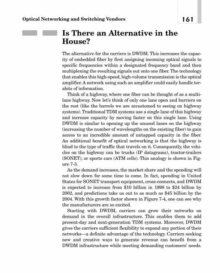
Is There an Alternative in theHouse?The alternative for the carriers is DWDM. This increases the capac-ity of embedded fiber by first assigning incoming optical signals tospecific frequencies within a designated frequency band and thenmultiplexing the resulting signals out onto one fiber. The technologythat enables this high-speed, high-volume transmission is the opticalamplifier. A network using such an amplifier could easily handle ter-abits of information.
Think of a highway, where one fiber can be thought of as a multi-lane highway. Now let’s think of only one lane open and barriers onthe rest (like the barrels we are accustomed to seeing on highwaysystems).Traditional TDM systems use a single lane of this highwayand increase capacity by moving faster on this single lane. UsingDWDM is similar to opening up the unused lanes on the highway(increasing the number of wavelengths on the existing fiber) to gainaccess to an incredible amount of untapped capacity in the fiber.An additional benefit of optical networking is that the highway isblind to the type of traffic that travels on it. Consequently, the vehi-cles on the highway can be trucks (IP datagrams), tractor-trailers(SONET), or sports cars (ATM cells). This analogy is shown in Fig-ure 7-3.
As the demand increases, the market share and the spending willnot slow down for some time to come. In fact, spending in UnitedStates for SONET transport equipment, cross-connects, and DWDMis expected to increase from $10 billion in 1998 to $24 billion by2002, and predictions take us out to as much as $45 billion by the2004. With this growth factor shown in Figure 7-4, one can see whythe manufacturers are so excited.
Starting with DWDM, carriers can grow their networks ondemand in the overall infrastructure. This enables them to add present-day and next-generation TDM systems. Moreover, DWDMgives the carriers sufficient flexibility to expand any portion of theirnetworks—a definite advantage of the technology. Carriers seekingnew and creative ways to generate revenue can benefit from aDWDM infrastructure while meeting demanding customers’ needs.
161Optical Networking and Switching Vendors
08_200023_CH07/Batesx 1/17/01 8:19 AM Page 161
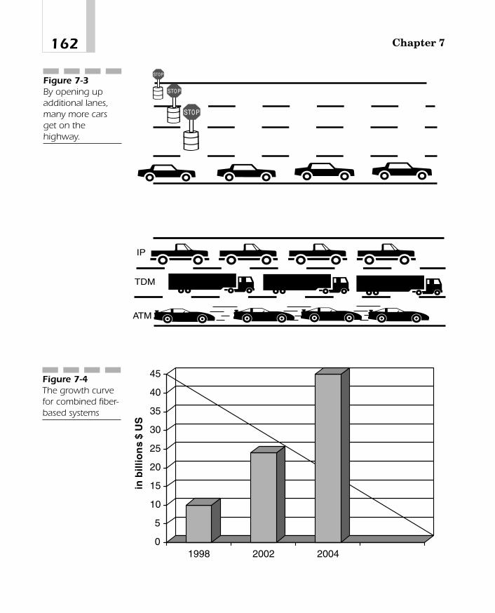
Chapter 7162
0
5
10
15
20
25
30
35
40
45
in b
illio
ns
$ U
S
1998 2002 2004
Figure 7-4The growth curvefor combined fiber-based systems
IP
TDM
ATM
Figure 7-3By opening upadditional lanes,many more carsget on thehighway.
08_200023_CH07/Batesx 1/17/01 8:19 AM Page 162

By partitioning and maintaining different dedicated wavelengths fordifferent customers, they can lease individual wavelengths—asopposed to an entire fiber—to their high-use business customers.
Compared with older equipment applications, DWDM alsoincreases the distances between network elements. This saves thecarriers significant upfront costs as they build out their networks.The optical amplifier component of the DWDM system saves costsby amplifying optical signals without converting them to electricalsignals.
Pay as You GrowA DWDM infrastructure provides a graceful network evolution forcarriers who need to meet their customers’ increasing capacitydemands. Because a DWDM infrastructure can deliver the neces-sary capacity expansion, driving a stake in the ground with DWDMis the best place to begin the migration to newer and more powerfultechnology. Taking smaller steps with DWDM enables the carriers toreduce initial costs while planning for future needs.
Some industry analysts rank DWDM as the perfect technology fornetworks requiring more bandwidth. However, these experts havenoted the conditions for this fit: a DWDM system must be scalable.Even though a carrier may install an OC-48 today with 32� chan-nels per fiber and it may seem as overkill, it will prove to be vision-ary and efficient two years hence. Thus, carriers can add bandwidthand turn on what they need when they need it. This provides themthe flexibility to grow without the big “hurdles” every time.
Bandwidth Demand Driven byGrowing CompetitionSince 1984, a trend developed throughout the world to encouragecompetition in the telecommunications sector through governmentderegulation and market-driven economic stimulation. Since
163Optical Networking and Switching Vendors
08_200023_CH07/Batesx 1/17/01 8:19 AM Page 163

competition was introduced, revenues and access lines have grown40 percent. However, investment in outside plant has increased 60percent. The 1996 Telecommunications Reform Act gave way to myr-iad new operators in the long-distance and local exchange markets.These new providers offered the promise of driving down costs. Theyalso offered to create demand for additional services and capacity.Moreover, early competition among long-distance carriers was basedmainly on price reduction. Today’s competitive advantage is built onmaximizing the capacity of the network and enhancing reliabilitythrough aggressive service-level agreements (SLAs).
Bandwidth demand increased as the carriers guaranteed fail-safenetworks. Telecommunications is critical to businesses and individ-uals today. Carriers agreed to guarantee fault tolerance and immu-nity from outages. In many cases, telephone companies includeservice-level guarantees in their contracts, with severe financialpenalties should outages occur.
To meet these requirements, carriers have broadened route diver-sity through either redundant rings or 1:1 point-to-point networks.Backup capacity is provided on alternate fibers. Achieving 100 per-cent reliability requires that spare capacity be set aside and dedi-cated only to a backup function. This can effectively double thebandwidth needed for an already strained and overloaded systembecause the “protective” path must equal the capacity of the “work-ing path.”
New ApplicationsConcurrently, the carriers are enhancing network survivability andaccommodating escalating demand for services such as video, high-resolution graphics, and large-volume data processing. Each appli-cation requires insatiable amounts of bandwidth. Frame Relay andATM also add to the demand. Internet usage, which is growing by100 percent annually, is threatening to overwhelm access networks.
Over the past 20 years, the telecommunications infrastructurehas been migrating to massive computerization and extensive use offiberoptic cables. The widespread use of fiber has been made possi-ble, in part, by the industry’s acceptance of SONET and SDH as the
Chapter 7164
08_200023_CH07/Batesx 1/17/01 8:19 AM Page 164

standards for signal generation. Using SONET/SDH standards, tele-phone companies gradually expanded capacity by increasing datarates to 2.488 to 10 Gbps.
Applications for DWDMAs with any new technology, the potential applications for DWDMare in their infancy. Many new applications will emerge that can takeadvantage of the capacities and capabilities of DWDM.Already it hasproven to be particularly well suited for several vital applications.
DWDM is ready-made for long-distance companies that use point-to-point or ring topologies. The immediate access to 16 new trans-mission channels—replacing one—dramatically increases theoperator’s chances of success and acceptance by the user community.
This increased capacity is critical to self-healing rings, which char-acterize today’s most sophisticated telecom networks. DeployingDWDM enables a carrier to construct a 100 percent protected ringusing two fibers. Operators building or expanding their networksalso will find DWDM as an economical opportunity to incrementallyincrease capacity. Network wholesalers can take advantage ofDWDM to lease capacity, rather than entire fibers, either to existingoperators or to new market entrants. DWDM will be especiallyattractive to companies that have low-fiber-count cables that wereinstalled primarily for internal operations but that could now beused to generate telecommunications revenue.
If You Cannot Build It, Buy ItWith all the movement in the industry, we also have to look at theoverall structure of the industry providers. In the early stages of theoptical networks, carriers and manufacturers emerged. Theseproviders were poised to build on the existing technologies andincrease the capacity, drive new demand, and innovate whereverpossible. However, the market heated up so quickly that many of thestodgy manufacturers were caught with their trunks down. Theysimply did not have the capacity in their trunking systems, nor were
165Optical Networking and Switching Vendors
08_200023_CH07/Batesx 1/17/01 8:19 AM Page 165

major capacity improvements on the horizon. Consequently, a newfeeding frenzy began. In 1998, the industry was thrust into a majorreeling under the inexplicable demands it had not anticipated. Thusthe stage was set for the acquisitions and merger mania that fol-lowed. In the year 1999-2000, the amount of activity exceededUS$110 billion in acquisitions (representing $25 billion in 1999 and$85 billion through October 2000).This is shown in Figure 7-5. Table7-4 is a more detailed listing of the action with the buyer, the com-pany it bought, and the valuation of the company. This is not an all-inclusive list, but it represents many of the larger transactions thattook place over these two years.
The graph Figure 7-6 is a breakdown of the major investments,but a word of caution is in order: Many of these manufacturers haveundisclosed amounts that they have invested in some of their acqui-sitions that are not shown here. This graph shows where the majormoney came from in the form of stock or cash purchases.
Building Block of the PhotonicNetworkDWDM is established as the fiberoptic system preferred for provid-ing bandwidth relief. Several carriers have settled on DWDM with 16 OC-48s as the technology of choice. With 16-channel DWDM
Chapter 7166
25,099
85,775
0
20,000
40,000
60,000
80,000
100,000
in m
illio
ns
$ U
S
1999 2000
Acquisitions and mergers
Figure 7-5The value ofacquisitions andmergers in 1999-2000
08_200023_CH07/Batesx 1/17/01 8:19 AM Page 166
TEAMFLY
Team-Fly®

167Optical Networking and Switching Vendors
Buying Company Company Bought Date Value
Nortel Networks Cambrian Systems Dec 98-Jan 99 $300 million
Lucent Technologies Sybarus Technologies Feb 99 Undisclosed
GEC Reltec Corporation Mar 99 $2.1 billion
Applied Micro Cimaron Mar 99 $115 millionCircuits Corp. Communications
SDL, Inc. IOC International Mar 99 $46 million
ADC Spectracom May 99 $105 millionTelecommunications
Optical Networks Object-Mart, Inc. May 99 Undisclosed
E-TEK Dynamics ElectroPhotonics May 99 $40 millionCorp.
Cypress Arcus Technology Jun 99 $20 millionSemiconductor
Cisco Systems Monterey Networks Aug 99 $500 million
Cisco Systems Cerent Corp. Aug 99 $7.2 billion
JDS Uniphase Ramar Corp. Oct 99 Undisclosed
JDS Uniphase SIFAM, Ltd. Nov 99 $2.8 billion
Redback Networks Siara Systems Nov 99 $4.7 billion
Corning Siemens AG Dec 99 $1.4 billionWorldwide Optical
Nortel Networks Qtera Dec 99 $3.25 billion
Cisco Systems Pirelli Optical Dec 99 $2.15 billionSystems
Conextant Systems Microcosm Jan 00 $180 millionCommunications
JDS Uniphase E-TEK Dynamics Jan 00 $15 billion
Lucent Technologies Ortel Feb 00 $2.95 billion
Corning NetOptix Feb 00 $2 billion
Agilent CSELT Optical R&D Feb 00 Undisclosed
ADVA Optical Storage Area Feb 00 $83 millionNetworks
Table 7-4
Acquisitions byVendor
continued
08_200023_CH07/Batesx 1/17/01 8:19 AM Page 167

Chapter 7168
Buying Company Company Bought Date Value
ADVA Optical Broadband Gmbh Feb 00 $22.9 million
SDL Veritech Microwave Feb 00 $590 million
Lucent Technologies Ignitus Mar 00 UndisclosedCommunications
Nortel Networks Xros Mar 00 $3.25 billion
Intel Giga A/S Mar 00 $1.25 billion
Nortel Networks CoreTek Mar 00 $1.43 billion
JDS Uniphase Cronos Apr 00 $750 million
Cisco Systems PentaCom Apr 00 $118 million
Corning NZ Applied Apr 00 $150 millionTechnologies
Agilent American Apr 00 UndisclosedHolographic
MRV Quantum Optech Apr 00 Undisclosed
MRV Optronics Apr 00 $234 millionInternational
MRV JOLT Apr 00 Undisclosed
ADC IBSEN May 00 $80 million
ADC Altitun May 00 $872 million
Corvis Algety Telecom May 00 Undisclosed
SDL Photonic Integration May 00 $1.8 billionResearch
Kymata BBV Design May 00 Undisclosed
Cisco Systems Qeyton Systems May 00 $800 million
Avanex Holographix May 00 $75 million
Nortel Networks Photonic Technologies May 00 $35.5 million
Lucent Technologies Chromatis Networks May 00 $4.5 billion
ADVA Optical First Fibre Jun 00 $83 million
Sycamore Networks Sirocco Systems Jun 00 $2.9 billion
Table 7-4 cont.
Acquisitions byVendor
continued
08_200023_CH07/Batesx 1/17/01 8:19 AM Page 168

169Optical Networking and Switching Vendors
10.968
7.15
2.1
59.647
7.88 8.265
4.72.4 2.9
0
10
20
30
40
50
60
Cisco
Corning
GEC
JDS U
niphaseLucent
Nortel
Redback
SDL
Sycamore
Value of InvestmentsFigure 7-6Categories ofmajor investmentsby vendor
Table 7-4 cont.
Acquisitions byVendor
Buying Company Company Bought Date Value
Lucent Technologies Hermann Technology Jun 00 $438 million
Alcatel Innovative Fibers Jul 00 $175 million
JDS Uniphase SDL, Inc. Jul 00 $41 billion
Cypress Silicon Light Machines Jul 00 $169 millionSemiconductor
Corning Willow Systems Aug 00 Undisclosed
Broadcom NewPort Aug 00 $1.25 billionCommunications
Corning Pirelli Optical Sep 00 $3.6 billionComponents
Kymata Total Micro Products Oct 00 Undisclosed
08_200023_CH07/Batesx 1/17/01 8:19 AM Page 169

now deployed throughout the carrier infrastructure, and with a 128-channel system coming, DWDM certainly will be a key ingredi-ent for interoffice interconnectivity. Indeed, deployment of DWDM isa critical first step toward the establishment of photonic networks inthe access, interoffice, and interexchange segments of today’stelecommunications infrastructure.
Given the rapidly changing and unpredictable nature of thetelecommunications industry, it is imperative that today’s DWDMsystems adapt to future deployments and network configurations.Open DWDM systems provide such flexibility to aid the carriers inplanning their future photonic network.
DWDM systems with open interfaces incorporate SONET/SDH,ATM, Frame Relay, asynchronous/PDH, and other protocols over thesame fiber. Open systems also eliminate additional high-performanceoptical transmitters to interface with specific protocols. Rather, opensystems enable service providers to quickly adapt new technologiesto the optical network with “off the shelf,” relatively inexpensive, andreadily available transmitters.
Conversely, proprietary DWDM equipment locks the carrier into asingle vendor, whereas open systems provide more freedom to provideservices and reduce long-term costs. Proprietary systems, in whichSONET/SDH equipment is integrated into the optical multiplexer-demultiplexer unit, are adequate for straight point-to-point configu-rations. Nevertheless, they require additional and costlytransmission equipment when deployed in meshed networks.
DWDM systems complying with the ITU standards assure thecarriers that they have systems with recognized industry standardsand the flexibility to grow their optical networks into long-distance,local exchange, and access networks. Given the amount of growthand flexibility available, Table 7-6 shows where the vendors will selltheir equipment and the marketplace for the near future. These fig-ures represent specific categories of users, along with U.S.-basedproviders only. Considering other market segments will increase thenumbers dramatically. This is still a place where we will expect tosee much activity.
Chapter 7170
08_200023_CH07/Batesx 1/17/01 8:19 AM Page 170

171Optical Networking and Switching Vendors
DWDM System: 1999 2003 2005
IXC/ISP backbones 3,300 3,376 3,700
ILEC 21 1,302 2,965
CLEC 52 581 1,890
Cable television 81 909 2,167
Enterprise 56 168 337
Optical cross-connects 12 1,299 2,387
TOTAL 3,521 7,935 13,446
Table 7-6
U.S. DWDMMarketProjections forUsers of DWDM(US$ Millions)
continued
The Final ListOne final list of vendors, which can never be all-inclusive, is defi-nitely something that warrants some consideration. This list isimpressive if only by sheer size.The intent is not to endorse one com-pany over another but to list some of the players that fall into thecategories of optical networking suppliers. Table 7-7 is the list ofvendors, but as stated, not 100 percent. This list is current as of thiswriting, but if a user is interested in any one of the providers, thenadditional research is necessary.
Accelight Networkswww.accelight.com
Acorn Networkswww.acorn-networks.com
ADC Telecommunicationswww.adc.com
ADVA Optical Networkingwww.advaoptical.com
Aetian Networkswww.aetian.com
Table 7-7
Vendor List(partial)
08_200023_CH07/Batesx 1/17/01 8:19 AM Page 171

AFCwww.afctek.com
Agility Communicationswww.agilitycom.com
Air Fiberwww.airfiber.com
Alcatel Optronicswww.alcatel.com/telecom/optronics
Algety Telecomwww.algety.fr
Alidian Networkswww.alidian.com
Allied Signalwww.honeywell.com
AllOptic, Inc.www.alloptic.com
Altitun ABwww.altitun.com
Amber Networkswww.ambernetworks.com
AMPwww.amp.com
Anda Networkswww.andanetworks.com
Anritsuwww.global.anritsu.com
Appian Communicationswww.appiancom.com
Apollo Photonicswww.apollophoton.com
Astral Pointwww.astralpoint.com
Astroterrawww.astroterra.com
Chapter 7172
Table 7-7 cont.
continued
08_200023_CH07/Batesx 1/17/01 8:19 AM Page 172

Atoga Systemswww.atoga.com
Atrica, Inc.www.atrica.com
Atoga Systemswww.atoga.com
Aurora Networkswww.aurora.com
Axsun Technologieswww.axsun.com
Avanexwww.avanex.com
Avici Systemswww.avici.com
Bandwidth9www.bw9.com
Bay Microsystemswww.baymicrosystems.com
Blaze Network Productswww.blazenp.com
Bookham Technologieswww.bookham.com
Bragg Photonicswww.braggphotonics.com
BrightLink Networkswww.corvia.com
Calient Networkswww.calient.net
Calix Networkswww.calix-networks.com
Caspian Networkswww.caspiannetworks.com
Catamaran Communicationswww.catamarancom.com
173Optical Networking and Switching Vendors
Table 7-7 cont.
continued
08_200023_CH07/Batesx 1/17/01 8:19 AM Page 173

Centerpoint Broadbandwww.centerpoint.com
Cerent Corporationwww.cerent.com
Chiaro Networkswww.chiaro.com
Chorum Technologieswww.chorumtech.com
Chromatis Networkswww.chromatis.com
Cicada Semiconductorwww.cicada-semi.com
Cidrawww.cidra.com
Cielo Communicationswww.cieloinc.com
Cienawww.ciena.com
Cierra Photonicswww.cierraphotonics.com
Cintawww.cinta-corp.com
Cirrexwww.cirrex.com
Cisco Systemswww.cisco.com
Codeon Corporationwww.codeoncorp.com
Cogniginewww.cognigine.com
Coherent Systemswww.coherentinc.com
CoreTekwww.coretekinc.com
Chapter 7174
Table 7-7 cont.
08_200023_CH07/Batesx 1/17/01 8:19 AM Page 174

Coriolis Networkswww.coriolisnet.com
Corviswww.corvis.com
Corningwww.corning.com
Crescent Networkswww.crescentnets.com
Cronos Integrated Microsystemswww.memsrus.com
Cspeedwww.cspeed.com
CyOpticswww.cyoptics.com
Cyraswww.cyras.com
DiCon Fiberopticswww.diconfiberoptics.com
Digital Lightwavewww.lightwave.com
Digital Optics, Inc.www.doc.com
Discovery Semiconductorswww.chipsat.com
Ditechwww.ditechcorp.com
Dynarcwww.dynarc.com
ECI Telecomwww.ecitele.com
Emcorewww.emcore.com
Ericssonwww.ericsson.com/transmission
175Optical Networking and Switching Vendors
Table 7-7 cont.
08_200023_CH07/Batesx 1/17/01 8:19 AM Page 175

E-TEK Dynamicswww.e-tek.com
Equipe Communicationswww.equipecom.com
ExceLight Communicationswww.excelight.com
EZchip Technologieswww.ezchip.com
Finisarwww.finisar.com
Free Electron Technologywww.freeelectrontechnology.com
Fujitsu Network Communicationswww.fnc.fujitsu.com
General Instrumentwww.gi.com
Geyser Networkswww.geysernetworks.com
Gigabit Opticswww.gigabitoptics.com
Gotham Networkswww.gothamnetworks.com
Growth Networks (now Cisco)www.growthnetworks.com
Harmonic, Inc.www.harmonicinc.com
Hitachi Telecomwww.hitel.com
IONAS A/Swww.ionas.com
Ilotronwww.ilotron.com
Iolonwww.iolon.com
Chapter 7176
continued
Table 7-7 cont.
08_200023_CH07/Batesx 1/17/01 8:19 AM Page 176
TEAMFLY
Team-Fly®

IP Photonicswww.iphotonics.com
Iridian Spectral Technologieswww.iridian.ca
Iris Groupwww.irislabs.com
IronBridge Networkswww.ironbridgenetworks.com
ITF Optical Technologieswww.itfoptical.com
Jasmine Networkswww.jasminenetworks.com
K2 Optronicswww.k2optronics.com
Kestrel Solutionswww.kestrelsolutions.com
Kymatawww.kymata.com
Lambda Crossingwww.lambdax.com
Lantern Communicationswww.lanterncom.com
LaserCommwww.lasercomm-inc.com
Latus Lightworkswww.latuslightworks.com
Laurel Networkswww.laurelnetworks.com
LGC Wirelesswww.lgcwireless.com
LightChipwww.lightchip.com
LightConnectwww.lightconnect.com
177Optical Networking and Switching Vendors
continued
Table 7-7 cont.
08_200023_CH07/Batesx 1/17/01 8:19 AM Page 177

LightLogicwww.lightlogic.com
LightSpeed Semiconductorwww.lightspeed.com
LiquidLightwww.liquidlightinc.com
Lightwave Microsystemswww.lightwavemicro.com
Lucent Technologieswww.lucent.com
Lumenonwww.lumenon.com
Lumentiswww.lumentis.se
Luminenthttp://www.luminentinc.com
Luminous Networkswww.lumnet.com
Lumos Technologieswww.lumos.com
LuxCorewww.luxcore.com
LuxNwww.luxn.com
LuxPath Networkswww.luxpath.com
Lynx Photonic Networkswww.lynx-networks.com
Mainsail Networkswww.mainsailnet.com
Mahi Networkswww.mahinetworks.com
Maple Networkswww.maplenetworks.com
Chapter 7178
Table 7-7 cont.
continued
08_200023_CH07/Batesx 1/17/01 8:19 AM Page 178

Mayan Networkswww.mayannetworks.com
Memlinkwww.mem-link.com
Metera Networkswww.metera.com
Metro-Optixwww.metro-optix.com
MetroPhotonicswww.metrophotonics.com
Microcosm Technologieswww.memcad.com
Micro Photonics Integrationwww.mpi-ioc.com
Molecular OptoElectronics Corporationwww.moec.com
Monterey Networks (now Cisco)www.montereynets.com
MRV Communicationswww.mrv.com
Nanovation Technologieswww.nanovation.com
NECwww1e.mesh.ne.jp
Net Insight ABwww.netinsight.se
NetOptixwww.ofccorp.com
Network Photonicswww.networkphotonics.com
NewCore Networkswww.newcorenetworks.com
New Focuswww.newfocus.com
179Optical Networking and Switching Vendors
Table 7-7 cont.
continued
08_200023_CH07/Batesx 1/17/01 8:19 AM Page 179

Newportwww.newportcom.com
Network Elementswww.networkelements.com
Network Photonicswww.networkphotonics.com
Nexsiwww.nexsi.com
Nishan Systemswww.nishansystems.com
Nortel Networkswww.nortelnetworks.com
Nova Crystalswww.novacrystals.com
Novaluxwww.novalux.com
NZ Applied Tech (now Corning)www.nzat.com
Ocean Opticswww.OceanOptics.com
Ocular Networkswww.ocularnetworks.com
ONI Systemswww.oni.com
Onix Microsystemswww.onixmicrosystems.com
Optical Micro Machineswww.omminc.com
Oplink Communicationswww.oplink.com
OpNextwww.opnext.com
OptComwww.scivac.com
Chapter 7180
Table 7-7 cont.
continued
08_200023_CH07/Batesx 1/17/01 8:19 AM Page 180

Opthoswww.opthos.com
Optical Capital Groupwww.opticalcapitalgroup.com
Optical Micro Machineswww.omminc.com
Optical Solutionswww.opticalsolutions.com
Optical Switch Corporationwww.opticalswitch.com
OptiMight Communicationswww.optimight.com
OptiSpherewww.optisphere.com
Optiwave Corporationwww.optiwave.com
Optix Networkswww.optixnetworks.com
OptoSpeedwww.optospeed.com
Opto Tronic ABwww.optotronic.com
Optranetwww.optranet.com
Optunwww.optun.com
OptXConwww.optxcon.com
Orika Networkswww.orikanetworks.com
Osicomwww.osicom.com
PacketLight Networkswww.packetlight.com
181Optical Networking and Switching Vendors
Table 7-7 cont.
continued
08_200023_CH07/Batesx 1/17/01 8:19 AM Page 181

Pandatelwww.pandatel.com
Phaethon Communicationswww.phaethoncommunications.com
Photoneticswww.photonetics.com
PhotonExwww.photonex.com
Photonic Materialswww.photonicmaterials.com
Photuriswww.photuris.com
PicoLightwww.picolight.com
Pluriswww.pluris.com
Precision Optics Corporationwww.poci.com
Princeton Lightwavewww.princetonlightwave.com
Qeyton Systemswww.qeyton.com
Qtera Corporation (now Nortel)www.qtera.com
Quake Technologieswww.quaketech.com
Quantum Bridgewww.quantumbridge.com
Quison Technologieswww.qusiontech.com
Rapid 5www.rapid5.com
Roshneewww.roshnee.com
Chapter 7182
Table 7-7 cont.
continued
08_200023_CH07/Batesx 1/17/01 8:19 AM Page 182

Santecwww.santec.com
SAN Valleywww.sanvalley.com
Scientific Atlantawww.sciatl.com
SiberCore Technologies, Inc.www.sibercore.com
Sirocco Systemswww.siroccosystems.com
Southampton Photonicswww.southamptonphotonics.com
Spectra Switchwww.spectraswitch.com
Sumimoto Electric Lightwave Companywww.sel-rtp.com
Surface Technology Systemswww.stsystems.com
SwitchCorewww.switchcore.com
Sycamore Networkswww.sycamorenet.com
Tejas Networkswww.tejasnetworks.com
Tektronixwww.tek.com
Telicawww.telica.com
Telopticawww.teloptica.com
Templex Technologywww.templex.com
Telliumwww.tellium.com
183Optical Networking and Switching Vendors
Table 7-7 cont.
continued
08_200023_CH07/Batesx 1/17/01 8:19 AM Page 183

Tenor Networkswww.tenornetworks.com
TeraBeamwww.terabeam.com
Terawave Communicationswww.terawave.com
Transcomm Technology Systems, Inc.www.transcomm.com
Transmodewww.transmode.se
Trellis Photonicswww.trellis-photonics.com
Trillium Photonicswww.trilliumphotonics.com
Virtual Photonicswww.virtualphotonics.com
Veliowww.velio.com
Wavesplitter Technologies, Inc.www.wavesplitter.com
World Wide Packetswww.worldwidepackets.com
Xros is now Nortelwww.xros.com
Xtera Communicationswww.xtera.com
Yavo Networkswww.yafonet.com
Zaffirewww.zaffire.com
Zenstrawww.zenastra.com
Chapter 7184
Table 7-7 cont.
08_200023_CH07/Batesx 1/17/01 8:19 AM Page 184

High-SpeedApplications
CHAPTER 88
09_200023_CH08/Batesx 1/17/01 8:20 AM Page 185
Copyright 2001 The McGraw-Hill Companies, Inc. Click Here for Terms of Use

Up to now, our discussions have dealt with the technologies, devel-opment, and competing products designed by the various manufac-turers. Some limited discussion also has taken us through the stepsof using the fiber and optical networking and switching at the carrierlevel. However, little discussion has taken place of the use of fiberand optical switching systems in the ever-increasing pool of applica-tions for the end users, carriers, and manufacturers combined.
The time to discuss the application and use of the fiber-based sys-tems is now. In this chapter, two major concepts must be addressed:making money and saving money. Making money represents the per-spective of the manufacturers. They will invest in research anddevelopment efforts to create products and goods that others want.These manufacturers will concentrate their efforts on the biggestreturn on investment (ROI) that they can possibly achieve. That is abusiness statement, not a criticism of the efforts of manufacturers.Once manufacturers arrive at a product, they will market this prod-uct for everything they can get from it. At the same time, they willalso look for spin-off applications to create a second wave of productsand applications that will fit the need. This is where the vendorsstart. The goal is to offer the product or service that will return prof-its greater than their expenses, meaning they want to make money.
While manufacturers are making money on their new products,they will be replacing other (older) technologies and products thathave lived through their life cycle and are returning less on theirinvestment. Therefore, the new and improved product will creategreater wealth with less cost. In this regard, the providers are savingmoney.
Simultaneously, the carriers will look at the new products and ser-vices offered by the manufacturers with one major goal in mind:Install this new product and create revenue streams that exceedtheir cost. Hence the carriers also want to use these new technolo-gies to make money. With the implementation of these new products,some measure of benefit is achievable. This may include
� Reducing the numbers of devices
� Increasing the number of calls/connections per fiber
� Adding new service levels beyond what was available initially
Chapter 8186
09_200023_CH08/Batesx 1/17/01 8:20 AM Page 186
TEAMFLY
Team-Fly®

In any of these choices, the outcome is that the carriers will reducetheir overall cost of operation, gaining more bang for their buck. Thiscreates the opportunity for the carriers to save money.
End users are continually working with manufacturers and carri-ers to realign their networks for their own benefit. While engagingboth the manufacturers and carriers, the end-user community cancreate new networking strategies, such as
� Improved speeds
� Increased throughput
� New services
� Greater connectivity to their remote sites
� Redundancy at the access level
� Internet access for e-commerce
� New marketing campaigns
Regardless of the specific application, the end users are trying todo one of two things:
1. Make money by increasing access to them from their customersor by expanding their e-commerce solutions
2. Save money by reducing the number of individual linksnecessary to provide higher capacity or increasing theredundancy without installing additional circuitry
As one can see, the overall goals of the three main characters inthis networking strategy happen to be the same. It is through thenew and improved use of optical networks and switching componen-try that this will occur for all three players.
Therefore, the next set of applications will deal with the use ofSONET/SDH in a networking environment, along with the benefitsthat can be derived. Starting with the beginning stages, the course ofaction will include looking at the following:
� SONET/SDH
� WDM/DWDM
� Optical switching
187High-Speed Applications
09_200023_CH08/Batesx 1/17/01 8:20 AM Page 187

Add-Drop Multiplexing: ASONET/SDH ApplicationA major application for using SONET/SDH is the ability to performadd-drop multiplexing. Although network elements are compatibleat the OC-n/STM-n level, they may still differ from vendor to vendor.SONET/SDH does not attempt to restrict all vendors to providing asingle product, nor does it require that they produce one of everytype out there. One vendor may offer an add-drop multiplexer withaccess to the DS-1/E-1 level only, whereas another may offer accessto DS-1/E-1 and DS-3/E-3 rates. The benefit of an add-drop multi-plexer on a wide-area network (WAN) is to drop (demultiplex) onlythe portions of the optical stream required for a location and let therest pass through without the demultiplexing process. It would beextremely inefficient to have to demultiplex an entire OC-12/STM-4,for example, only to drop out one DS-1/E-1.The ability to extract onlywhat is necessary helps to prevent errors, loss of data, and otherdelays inherent in older technologies. The add-drop multiplexermakes this attractive for carriers to use in rural areas, where theymay bundle many lower-speed communications channels onto a sin-gle OC-1 or OC-3/STM-1 to carry the information back to a centralmetropolitan area. Moreover, beyond just dropping a digital signalout of a higher-speed OC-n/STM-n, the carrier can fill in what hasbeen vacated (for example, if a DS-1 is dropped off along the opticalpath, a new DS-1 can be multiplexed back into the OC-3 in its place).This provides the carriers with considerable flexibility. Figure 8-1shows an add-drop multiplexer. Here, portions of the bandwidth canbe dropped off and additional new signals can be added in place ofthe data stream dropped out of the higher-speed signal. A single-stage add-drop multiplexing function can multiplex various inputsinto an OC-n signal. At an add-drop site, only those signals whichneed to be accessed are dropped and inserted. The remaining trafficcontinues through the network switching system without requiringspecial processing. The figure shows a local traffic conventionwhereby the necessary traffic is added or dropped as appropriate.
Chapter 8188
09_200023_CH08/Batesx 1/17/01 8:20 AM Page 188

Figure 8-2 provides a slightly more detailed look at the applicationof add-drop multiplexing within a longer-haul circuit. Here, theinputs at location A are multiplexed into a DS-3 and then onto a
189High-Speed Applications
Express through traffic
OADMMUX
MUX
MUX
Local traffic Local traffic
Figure 8-1Add-dropmultiplexing withSONET/SDH
OADM
DS11
28
DS3 OC-1 OC-1 DS3
DS1
1
28
69 15
24
RouterRouter CSU/DSUCSU/DSU
Fiber circuits dropped of to location "B" and added back in to location "C"
OADM
Figure 8-2Add-drop on thelong haul circuit
09_200023_CH08/Batesx 1/17/01 8:20 AM Page 189

fiber-based OC-1. As the circuit is taken across the long-haul net-work, it may pass through amplifiers or regenerators in aSONET/SDH environment. At location B, a few DS-1s are droppedoff, and new ones are inserted back into the empty time slots to becarried back to location A or on to location C depending on the need.This is a better way of viewing the true use of add-drop multiplexing.
SONET/SDH TopologiesSeveral different topologies can be employed in a SONET/SDH net-work, using the various multiplexers to satisfy the high-speed needsof the carrier or the end user. These include the normal topologiesmost networks have been accustomed to over the years, including
� Point-to-point
� Point-to-multipoint
� Hub-and-spoke
� Ring
� Dual counter-rotating rings
These variations provide the flexibility of SONET/SDH in local-and wide-area networks built by the carriers. These are now becom-ing the method of choice at many large organizations too. In each ofthe topologies, larger organizations are finding the benefits ofinstalling highly reliable interoperable equipment at the private net-work interfaces and access to the public networks.
Point-to-Point
The SONET/SDH multiplexer, the entry level for an organization,acts as a concentrator for multiple lower-speed communicationschannels such as DS-1/E-1 and DS-3/E-3. This equipment may beacquired by the end user, or it may be provided as the customerpremises equipment (CPE) by the carrier (ILEC, CLEC, and IEC). In
Chapter 8190
09_200023_CH08/Batesx 1/17/01 8:20 AM Page 190

its simplest form, two devices are connected with an optical fiber(with any repeaters as necessary) as a point-to-point circuit. As theentry-level point into SONET/SDH architecture, the inputs and out-puts are identical. In this environment, the network can act as astand-alone environment and not have to interface with the publicswitched networks. Figure 8-3 shows a point-to-point multiplexingarrangement.
While considering this, the application may be to bundle multiplecommunications channels together, replacing the leased linesinstalled for each application. If one considers the use ofSONET/SDH, many lower-speed applications can be bundledtogether into a single high-speed communications channel using apoint-to-point circuit. In this case, no add-drop multiplexing isrequired because all the bandwidth is used between the same twoends. Figure 8-4 shows some of the lower-speed communicationschannels.
Figure 8-5 shows the same services bundled together onto a singleOC-1 to carry all the services between the two ends. Note that thisfigure goes beyond the replacement of individual slower circuits witha high-speed and accelerated communications channel to satisfy thedemands that were not being met initially.
191High-Speed Applications
OC-N
OC-N
OC-N
OC-N
Figure 8-3Point-to-pointservices withSONET/SDH
09_200023_CH08/Batesx 1/17/01 8:20 AM Page 191

Chapter 8192
CODEC
DS1
E1
DS1
2-DS1
Host
LAN
Controller
RouterRouter
CODEC
Video
PBXPBX
Dumb TerminalsLocation "A" Location "B"
TV
Figure 8-4Point-to-pointapplications usinglow-speedcommunications
CODEC
Host
LAN
Controller
RouterRouter
CODEC
Video
PBX PBX
Dumb Terminals
Location "A" Location "B"
TV
TelcoTelco MUXMUXOC-12OC1 OC1
DS1
16 Mbps
6 Mbps
DS
1D
S1
1.5 DS1
1.5 DS1
6 Mbps
16 Mbps
1.5 DS1
Figure 8-5Bundled serviceson a point-to-pointSONET OC-1 circuit
09_200023_CH08/Batesx 1/17/01 8:20 AM Page 192

Point-to-Multipoint
The next step is to consider the point-to-multipoint arrangement.This will use a form of add-drop multiplexing to drop circuits offalong the way. In a large corporate network spanning the country (orany subset), a single high-speed link may be employed. The SONETadd-drop multiplexer (ADM) is used for the task at hand, droppingcircuits out without demultiplexing the entire high-speed signal.Figure 8-6 shows an ADM installed between two far-end locations sothat signals can be added or dropped off as necessary. This is a bet-ter solution than renting three different circuits between points AB,AC, and BC, which adds to the complexity and cost. By using a cir-cuit from A to B to C with ADMs, the service usually can be accom-modated more efficiently.
Hub-and-Spoke
The hub-and-spoke method (sometimes referred to as a star net-work) enables some added flexibility in case of unpredicted growth or constant changes in the architecture of the network. A SONET/SDH
193High-Speed Applications
OC-1
LA
terminate 22 DS1originate 22 DS1
drop off6 DS1, add 6 DS1 east
Phoenix
Chicago
Bostondrop off4 DS1s
insert 2 DS1 eastinsert 2 DS1 west
OC-1
Figure 8-6ADMs installedalong the way of amultipoint circuit
09_200023_CH08/Batesx 1/17/01 8:20 AM Page 193

multiplexer can be hubbed into a digital cross-connect, where it isconcentrated and then forwarded onto the next node. This is used inmany larger organizations where regional offices are located and dis-trict or branch offices are tied into the network through the hub.Again, the flexibility is available if a major change occurs in the net-work architecture or in case of major campaigns in the organization.Hubs will act as the cross-connect points to link the various echelonsin the network together. These may be developed in a blocking ornonblocking manner. Typically, some blocking may be allowed. Thehub-and-spoke arrangement is shown in Figure 8-7.
Ring
In a ring architecture, where SONET/SDH automatic protectionswitching is employed, the best of all worlds comes to fruition. Thering topology uses ADMs throughout the network, and a series ofpoint-to-point links is installed between adjoining neighbors. Thebidirectional capability places the most robustness into the network;however, unidirectional services also can be installed. The primaryadvantage of the ring architecture is survivability in case of a cablecut or a failure in a network node. The multiplexers have sufficientintelligence to reroute or reverse direction in case of a failure. If morethan one fiber link is installed, the systems could use alternatepaths, but they must recover in milliseconds (ms) which APS on
Chapter 8194
OC-3
OC-1
OC-1
OC-1
OC-1
OC+1
OC-1
Figure 8-7Hub-and-spokearrangement in aSONET/SDHmultiplexernetwork
09_200023_CH08/Batesx 1/17/01 8:20 AM Page 194

SONET/SDH is designed to do. Figure 8-8 shows the ring topologywith dual fibers run (bidirectional service) between the ADMs.
Ring topologies also may be used as access methods to providerobust services to the Internet. Figure 8-9 shows a ring of OC-3sinstalled for a large organization looking for redundancy andresiliency in the network. In this case, the access methods areinstalled by the carriers to different carriers (AT&T World Net andUUNet). If a single failure occurs, the network will begin to immedi-ately close the circle and offer the customer high-speed and reliablecommunications all at the same time. Regardless of the application,this redundant-ring topology assures the customer of availabilitywithout the wait. The network will likely heal and begin the alter-nate routing in less than 10 ms. At one point, this form of internet-working would have been too expensive for customers to afford andfor carriers to install. With all the changes in bandwidth allocationand the technology improvements, networks like this are becomingcommon.
Access MethodsOne of the major issues always facing end users and local carriers isthat of access. Users are now more sophisticated in their desires.They no longer want to settle for just any service. Instead, they
195High-Speed Applications
ADM ADM
Figure 8-8Ring architecture ofSONET/SDHmultiplexers
09_200023_CH08/Batesx 1/17/01 8:20 AM Page 195
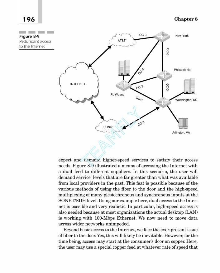
expect and demand higher-speed services to satisfy their accessneeds. Figure 8-9 illustrated a means of accessing the Internet witha dual feed to different suppliers. In this scenario, the user willdemand service levels that are far greater than what was availablefrom local providers in the past. This feat is possible because of thevarious methods of using the fiber to the door and the high-speedmultiplexing of many plesiochronous and synchronous inputs at theSONET/SDH level. Using our example here, dual access to the Inter-net is possible and very realistic. In particular, high-speed access isalso needed because at most organizations the actual desktop (LAN)is working with 100-Mbps Ethernet. We now need to move dataacross wider networks unimpeded.
Beyond basic access to the Internet, we face the ever-present issueof fiber to the door. Yes, this will likely be inevitable. However, for thetime being, access may start at the consumer’s door on copper. Here,the user may use a special copper feed at whatever rate of speed that
Chapter 8196
New York
Philadelphia
Washington, DC
OC-3
OC
-3
OC-3
OC
-3
Arlington, VA
OC-3
Ft. WayneOC-3
OC-3
UUNet
AT&T
INTERNET
Figure 8-9Redundant accessto the Internet
09_200023_CH08/Batesx 1/17/01 8:20 AM Page 196
TEAMFLY
Team-Fly®

can be sustained on such a local feed. At the incumbent localexchange carrier (ILEC) (or competitive local exchange carrier[CLEC]) office, a digital cross-connect system will bundle the accesslines together onto a SONET/SDH channel at OC-1, OC-3/STM-1,OC-12/STM-4, or higher. This is shown in Figure 8-10, where thelocal loop is still copper, but fiber services are applied at the ILECoffice. An alternative to the copper feed is the possibility that thelocal exchange carrier (LEC) may have a digital subscriber loop,using fiber on what it calls the digital loop carrier (DLC). In thiscase, the fiber enables higher-speed access.
Another possibility, shown in Figure 8-11, is the use of integratedaccess services. The customer may choose to install a DS-3 (T-3) tothe door to support the following services:
� Voice at the PBX, which may be using one or more T-1s
� LAN using a 10-Mbps feed from an Ethernet router
� Other data services
197High-Speed Applications
Ethernet LAN
Workstation
Server
Access Router
ILEC SLC (or DLC)
MDF
Access Node
Fiber
ILEC Central Office
Digital Cross Connect
Core Router
INTERNET
Copper Loop
ConditionedCircuit
OC-12
Figure 8-10Looking outwardfrom theconsumer’s door
09_200023_CH08/Batesx 1/17/01 8:20 AM Page 197

These can all be combined at the local loop and then carriedthrough a channel bank or multiplexer to the LEC office. At the LECoffice, the T-1s can be dropped off into the voice switch for circuit-switching needs (dial-up voice). Meanwhile, the data continuesthrough a digital cross-connect system to a core router. This willenable Internet access at 10 Mbps. Combinations of such services arealmost endless. The common denominator is the use of high-endmultiplexers in the LEC office to bundle the services onto a fiber-based architecture such as SONET/SDH.
Alternative Approaches to MultipleServices DeliveryAs we continue to escalate the speed of data networks, we hear manyarguments about the best way to carry the traffic. The Internet Pro-tocol (IP) is now the most common form of data that we need to send
Chapter 8198
Hub T1
Digital Cross Connect(DACS)
Core Router
INTERNET
10 Mbps T3
Channel Bank
PBX or Key System
Telephone CompanyVoice Switch
OC-12
DNS
Secondary DNS
Radius/Security
OC-3
T1
Figure 8-11Combining servicesonto a DS-3 andthen multiplexingonto SONET
09_200023_CH08/Batesx 1/17/01 8:20 AM Page 198

across our networks. A lot of discussion entered the market regard-ing the use of IP over various data networking protocols and differ-ent layers of the OSI model.
IP will run anywhere that we want it. The issue is not whether itcan be done, but whether we want to do it? Sales and marketing peo-ple with a personal stake in selling specific products entered theforay with a statement that Asynchronous Transfer Mode (ATM) wastoo expensive to use for IP datagrams (packets).Therefore, data com-munications manufacturers developed a marketing strategy to han-dle IP over SONET (POS) instead of ATM. At the time, the entireindustry was leaning toward IP over ATM. Soon everyone wasexpounding the benefits of running IP over SONET. Therefore, entera new group of people who began to espouse the benefits of runningIP over dense-wave-division multiplexing (DWDM) without the useof ATM or SONET.
A number of alternative approaches were developed to addressthe limitations of traditional SONET in multiservice access net-works. These alternatives include IP over ATM over SONET, IP overSONET (packet on SONET), and IP over DWDM. The protocolstacks for these three approaches are shown in Figure 8-12.
199High-Speed Applications
IP
ATM
SONET
Optical
IP
IPSONET
Optical Optical
Services Services Services
ATMTransport
Packet overSONET
IP over Fiber
Figure 8-12Variousapproaches tocarrying IP
09_200023_CH08/Batesx 1/17/01 8:20 AM Page 199

The first approach adapts all services to ATM cells, which are thentransported over an optical network using a concatenated SONETframe. Several standards address this approach, including TelcordiaGR-2837, which defines ATM virtual path support on SONET rings,and Telcordia GR-2842, which presents requirements for ATM-basedaccess multiplexers. The second approach adapts services to IPframes for transport over an optical network using either a channel-ized or a concatenated SONET frame. The IETF multiprotocol labelswitching (MPLS), differentiated services (Diffserv), and resourcereservation services protocol (RSVP) standards address a number ofissues associated with this approach. The third approach againadapts all services to IP frames for transport directly over an opticalnetwork. However, this approach eliminates the intermediateSONET layer. Each of these approaches has the potential to increasebandwidth utilization on fiber access networks.
Many network operators plan to use ATM over SONET for inte-grated delivery of services because of its support for a wide range ofservice types and its robust and mature quality-of-service (QoS) fea-tures. Telcordia’s GR-2837 standard defines several approaches tosupport of ATM traffic on fiberoptic rings. The most efficient of theapproaches uses a concatenated SONET frame, eliminating theSONET virtual tributary (VT) structure while retaining the sectionand line overhead bytes. Using ATM technology increases the gran-ularity of transport bandwidth to minimize the wasted bandwidthresulting from using the traditional SONET hierarchy. ATM overSONET technology also supports fast automatic protection switch-ing at the ATM virtual path level or the SONET layer. Thisaddresses one drawback of earlier approaches to protection switch-ing using ATM virtual channels or IP routing table recalculations,which were much slower. Finally, current ATM over SONET tech-nology accommodates ring network topologies rather than assumingpoint-to-point or mesh topologies. This enables the technology to beused on fiber access rings that are prevalent in many parts of theUnited States. Figure 8-13 is a representation of what can be gainedor lost by eliminating any of the protocols or layers in the OSI.
Services may be established on an on-demand basis using ATMswitched virtual circuit (SVC) signaling. QoS features also includemore efficient allocation of bandwidth on access networks by provid-
Chapter 8200
09_200023_CH08/Batesx 1/17/01 8:20 AM Page 200
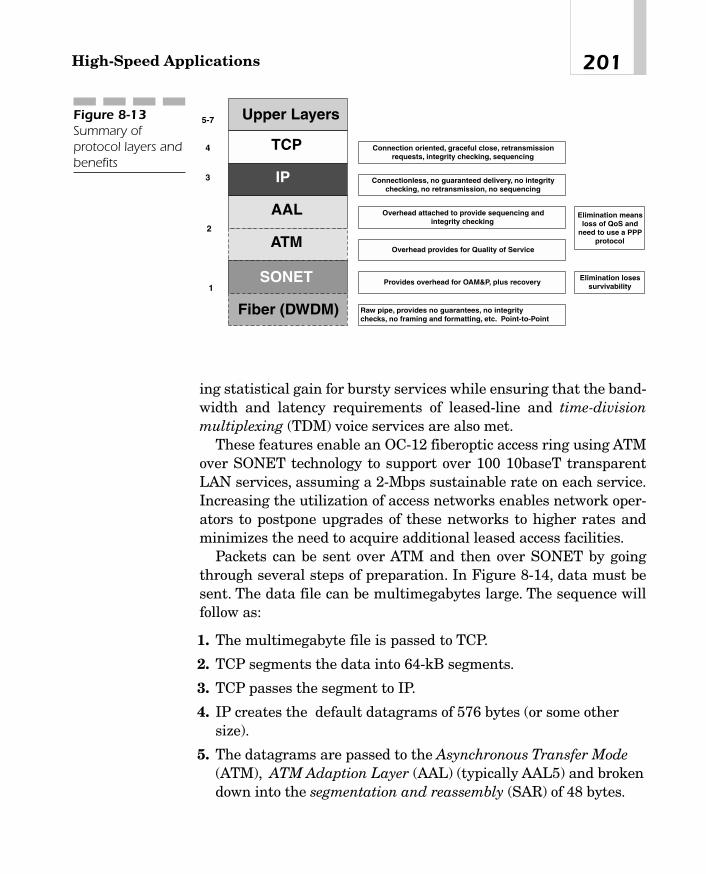
ing statistical gain for bursty services while ensuring that the band-width and latency requirements of leased-line and time-divisionmultiplexing (TDM) voice services are also met.
These features enable an OC-12 fiberoptic access ring using ATMover SONET technology to support over 100 10baseT transparentLAN services, assuming a 2-Mbps sustainable rate on each service.Increasing the utilization of access networks enables network oper-ators to postpone upgrades of these networks to higher rates andminimizes the need to acquire additional leased access facilities.
Packets can be sent over ATM and then over SONET by goingthrough several steps of preparation. In Figure 8-14, data must besent. The data file can be multimegabytes large. The sequence willfollow as:
1. The multimegabyte file is passed to TCP.
2. TCP segments the data into 64-kB segments.
3. TCP passes the segment to IP.
4. IP creates the default datagrams of 576 bytes (or some othersize).
5. The datagrams are passed to the Asynchronous Transfer Mode(ATM), ATM Adaption Layer (AAL) (typically AAL5) and brokendown into the segmentation and reassembly (SAR) of 48 bytes.
201High-Speed Applications
Upper Layers
TCP
IP
AAL
ATM
1
2
3
4
5-7
SONET
Fiber (DWDM)
Connection oriented, graceful close, retransmissionrequests, integrity checking, sequencing
Connectionless, no guaranteed delivery, no integritychecking, no retransmission, no sequencing
Overhead attached to provide sequencing andintegrity checking
Overhead provides for Quality of Service
Provides overhead for OAM&P, plus recovery
Raw pipe, provides no guarantees, no integritychecks, no framing and formatting, etc. Point-to-Point
Elimination meansloss of QoS and
need to use a PPPprotocol
Elimination losessurvivability
Figure 8-13Summary ofprotocol layers andbenefits
09_200023_CH08/Batesx 1/17/01 8:20 AM Page 201

6. The SAR is passed to the ATM layer, where the 5-byte header isattached, creating the cell.
7. The 53-byte cells are mapped onto a SONET frame in ahorizontal format.
8. The SONET frame is transmitted across the fiber link.
What about the Metropolitan-AreaNetworks?Manufacturers are now addressing the metropolitan-area optical-transport architecture based on dedicated optical networks connect-ing wavelength-routed and traditional IP systems. New products areappearing with DWDM, adding dynamic add-drop functions andusing broadband active optical amplifiers, when necessary, to extendsystem reach or cut the number of optoelectronic conversions withinthe metropolitan region.
Passive DWDM was limited in metropolitan areas compared withthe success of long-haul systems. This is due mainly to the LECs(ILECs and CLECs) being separated from the protection switchingand provisioning capabilities in a DWDM environment. The newersystems were designed to overcome these limitations by providingeither protected or unprotected channels.The optical subsystem uses1,310-nanometer (nm) short-reach lasers. Transceivers can be con-figured via software for OC-3, OC-12, or OC-48 rates.
Essentially, two choices are available for community networks inthe metropolitan areas: lease or build. Most large corporations withmetropolitan-area networking needs lease services from carriers.Many carriers have built their own highly resilient SONET rings inurban areas to serve various customers with leased lines connectingto that ring. Common services include T-1, T-3, Frame Relay, and OC-3 dedicated lines. This is shown in Figure 8-15, where the configura-tion uses a SONET architecture.
A real need exists among local communities, governments, andschool districts today to obtain cost-effective high-speed communica-tions access to enable new multimedia applications such as distance
Chapter 8202
09_200023_CH08/Batesx 1/17/01 8:20 AM Page 202

20
3H
igh-S
peed
Ap
plication
s
User Data at any size (Mbytes)
TCP Segments at
up to 64 KBytes
TCP Segments at
up to 64 KBytes
TCP Segments at
up to 64 KBytes
TCP Segments at
up to 64 KBytes
TCP Segments at
up to 64 KBytes
IP Datagrams at 576 Bytes
53 Bytes Cell
ATM Cells at 53
Bytes
33 Bytes (Portion of an ATM Cell)
53 Bytes Cell20 Bytes (Portion of Cell)
Figure 8-14Multistep process of handling IP over SONET
09_200023_CH08/Batesx 1/17/01 8:20 AM Page 203

learning/training, telemedicine, global information systems, intra-nets for e-mail and shared databases/applications for e-government,and business-to-government (B2G) and extranet access. Individualagencies and school districts usually build independent islands ofinformation technology around themselves, isolated from eachother. Different software and hardware platforms are deployed, andinformation cannot be shared. These entities failed to leverage theireconomies of scale for greater buying power. This has resulted inhigher communications and information technology costs and dupli-cation of effort.
Things are changing, however. Innovative communities are col-laborating to pool resources to create new network infrastructuresthat enable higher-performance networked applications at loweroverall costs. By building a high-speed communications grid amongpublic entities, a community may be able to break down traditionalbarriers and streamline operations by reducing duplicated efforts.Figure 8-16 shows how this might work.
Chapter 8204
SONET RingOC-12OC-48OC-192
T1/E1, T3, OC-3Frame Relay, ATM
SONETadd-drop MUX
L2/L3 SwitchFigure 8-15The metropolitanSONET network
09_200023_CH08/Batesx 1/17/01 8:20 AM Page 204

Applications for DWDMAs with many new technologies, the potential for DWDM is still inits infancy. However, the technology already has proven to be partic-ularly well suited for several vital applications. DWDM is ready-made for long-distance telecommunications operators that use eitherpoint-to-point or ring topology. The sudden availability of many newtransmission channels as opposed to only one increases a carrier’sability to expand capacity and simultaneously set aside backupbandwidth without installing new fiber.
The huge capacity afforded by DWDM is critical to the develop-ment of self-healing rings, which is characteristic of most sophisti-cated telecom networks. By deploying DWDM terminals, an operatorcan construct a 100 percent protected 40-Gbps ring with multiplecommunications signals using only two fibers.
205High-Speed Applications
City HallData Center
City Correctional Facility(or Courthouse)
Human Services Department
School District
Libraries
Residential
Public Utilities
Police and Fire DepartmentsHospital, Clinics
Park and Recreation
Source: 3Com
Figure 8-16Communities ofinterest areemerging (3Com)
09_200023_CH08/Batesx 1/17/01 8:20 AM Page 205

Carriers planning their capacity for current or future needs alsofind DWDM as an economical way to do the following:
� Incrementally increase capacity
� Rapidly provision new equipment for needed expansion
� Future-proof their infrastructure against unforeseen bandwidthdemands
Wholesalers can take advantage of DWDM to lease capacity (ratherthan entire fibers) either to existing operators or to new marketentrants. DWDM will be especially attractive to companies that havelow-fiber-count cables that were installed primarily for internaloperations but that could now be used to generate telecommunica-tions revenue. In the past, many carriers were smug with the ideathat they installed plenty of spare fibers in their rights of way.There-fore, these carriers stated that they could just light up another fiberrather than install the DWDM multiplexers and switches. This mayhave been true in the past, but as things progressed, the fibers wereconsumed, and the demand for new bandwidth continued to escalate.Using DWDM in the metropolitan area breathes new life into thesecarriers’ networks.
DWDM system transparency to various bit rates and protocolswill enable carriers to tailor and segregate services to various cus-tomers along the same transmission routes. DWDM enables a car-rier to provide STM-4/OC-12 service to one customer andSTM-16/OC-48 service to another all on a shared ring. In regionswith a fast-growing industrial base, DWDM is one way to utilize theexisting thin fiber plant to quickly meet burgeoning demand.
Building Block of the OpticalNetworkDWDM is now entrenched as the preferred method to relieve thebandwidth constraint many carriers face. Several U.S. carriers havesettled on DWDM at 16 times the OC-48 rate to gain more capacity.DWDM deployments throughout the carrier infrastructure will con-
Chapter 8206
09_200023_CH08/Batesx 1/17/01 8:20 AM Page 206
TEAMFLY
Team-Fly®

tinue to be an essential element of future interoffice fiber systems.DWDM is a critical first step toward the establishment of photonicnetworks in the access, interoffice, and interexchange segments ofthe telecommunication infrastructure. Figure 8-17 is an example ofoptical access links using the DWDM architecture in the metropoli-tan area.
DWDM systems with open interfaces give operators the flexibilityto provide SONET/SDH, asynchronous/PDH, ATM, Frame Relay,and other protocols over the same fiber. Open systems enable thecarriers to quickly adapt new technologies to the optical networkusing “off-the-shelf,” relatively inexpensive, and readily availabletransmitters.
Open interfaces provide operators with greater freedom to provi-sion services and reduce long-term costs. Proprietary-based systems,in which SONET/SDH equipment is integrated into the optical mul-tiplexer-demultiplexer unit, are adequate for straight point-to-point
207High-Speed Applications
Repeaters
Source: Alcatel
Figure 8-17Optical access inmetropolitannetworks (Alcatel)
09_200023_CH08/Batesx 1/17/01 8:20 AM Page 207

configurations. However, they require additional and costly trans-mission equipment when used in meshed networks.
In just under two years, DWDM has become an industry standardthat will find acceptance in any carrier environment. Therefore,DWDM
� Allows new services to come online more quickly.
� Contains costs so that customers can afford new services.
� Overcomes technological barriers associated with moretraditional solutions.
Newer applications emerge using the hybrid combinations of pas-sive optical networks (PONs) in a community alongside of the coax-ial systems serving broadband communications in the business andresidential market. The use of different wavelengths in this marketmakes the combinations that much more attractive and economical.This combined networking strategy with DWDM in the metropolitanarea is shown in Figure 8-18.
Chapter 8208
Source: Alcatel
HFC
PON
Residential Area Network
Enterprise AreaNetworks
Figure 8-18Combining servicesin the metropolitanarea (Alcatel)
09_200023_CH08/Batesx 1/17/01 8:20 AM Page 208

Metropolitan-area networks (MANs) are “hot buttons” for variousproviders. The current state of innovation and integration is shiftingaway from the WANs to the last mile and across citywide-area net-working strategies. These core networks are changing the way carri-ers perceive their ability to use and deploy their bandwidth. WANswere the building blocks in the middle to late 1990s. However, thenew century marks the investment strategies for the ILECs andCLECs (data CLECs also). Tremendous growth in access capacity isthe new marketplace for the infrastructure. These MANs will spanthe range of applications from the areas covered in Table 8-1.
The services we saw earlier in the discussion of technologies arenot different. Each has a need for dedicated high-speed or sharedhigh-speed communications across the MAN. Figure 8-19 shows theareas of concentration as the primary means of using the MAN andseparate wavelengths in support of each of the market drivers.
One additional area is the use of a combination of localized com-munications access methods through a multiplexer (that is, OC48/192) connected into a digital cross-connect system at the local car-rier network. At the carrier location, the introduction of wave-divi-sion multiplexers (WDM/DWDM) into the same cross-connectsystem will be handled. From there, the fibers will carry the variouswavelengths to a switch, where the information will be optically
209High-Speed Applications
Data center operations across town
Financial institutions with personnel spread across the broad area of a city
Planning for disaster recovery services to a “hot site” location
Mainframe access and Escon services to legacy applications
Backup and storage of network appliances and services
High-speed Internet access
Mission-critical services such as storage-area networks
FDDI distribution and MAN access
Multimedia applications
Table 8-1Services Drivingthe Use of DWDMacross MANs
09_200023_CH08/Batesx 1/17/01 8:20 AM Page 209

Chapter 8210
Storage area networks Storage area
networks
Enterprise
Escon EsconFiber channel Fiber channel
Long-Haulnetwork
Fiber channelFiber channel
Figure 8-19The services usingthe bandwidth
WDM
WDM
Opticaltransport layer
Cross Connect
Cross Connect
OC-48
OC-192
OC-48
ADM
ADM
Source: NEC
Switch SwitchFigure 8-20Local switching inan opticalarchitecture (NEC)
switched across town at the optical layer. Finally, the informationwill be extracted in the reverse order back down to the cross-connectand to any multiplexers on a local ring or multiplexer as necessary.This configuration is shown in Figure 8-20.
09_200023_CH08/Batesx 1/17/01 8:20 AM Page 210

The Wide-Area NetworkWhen provisioning for the long-haul networks, the carriers have totake into account that they will interface with local providers, that is,unless they become the local provider too. However the interconnec-tion is made, the wide area is where most of the infrastructure wasbuilt in the past because of the economics of providing the fiber-based (SONET/SDH) networks to carry long-distance traffic andconsolidated data communications. This worked, but as seen, thenew battlefront is at the metropolitan area. Thus, when the commu-nications providers use their interconnectivity, they must take intoaccount how they will link the metropolitan and wide areas together.An example of this form of interconnection is the use of data andvoice communications linked together on a WAN. In this application,a combination of access methods can be suitable, such as FrameRelay, ATM, and Internet leased-line access through the metropoli-tan network and interconnected across the wider area, as shown inFigure 8-21.
In some cases, the long-distance network will be used to provisiona high-speed data network for a large organization at OC-3/OC-12speed (or STM-1/STM-4) to link corporate sites with a dedicated pri-vate-line network service. In this case, the application is raw speedat the 622-Mbps rate, but this can be subdivided into multiple lower-speed communications channels, or it can be packetized and carry
211High-Speed Applications
ATM Switch
Router
Metro/Access
Frame Relay
Optical Switch Optical Switches
Optical Switches
Local Provider Long Distance Local Providers
Metro/Access
Metro/Access
ILEC
CLEC
Internet
Figure 8-21InterconnectingMANs and WANs
09_200023_CH08/Batesx 1/17/01 8:20 AM Page 211

voice over data, data, video, and multimedia on the same communi-cations channels. This provision enables the long-distance carriers toallocate and multiplex as much bandwidth as the customer needs ina private-line service between the two ends, as shown in Figure 8-22.
In the long-distance network, the SONET and SDH services canbe used to provide a series of interconnected ring topologies thatenables the carrier to provide the redundancy and resiliency of thenetwork as needed. Figure 8-23 shows a series of interlocking ringsused to provide full service and availability in case of a disaster (forexample, backhoe fade when a backhoe digs up the cables). Theseinterconnected rings may provide a full 1:1 protection circuit for theentire OC 12/48 network, or they may be 1:n (where n is 3, 4, or 5),enabling mission-critical services to be covered even though somelower-priority circuits may not be 100 percent backed up. Thisenables the carrier to provision as much as necessary in order tomeet the critical need without overpopulating a network fornonessential services. This is more of an economic decision than anyother consideration. Regardless of the level of backup coverage, thecarriers use the interconnected rings for their benefit as well as forthat of the customer.
Chapter 8212
Optical SwitchOptical Switch
Metro AccessILEC/CLEC
Optical Private Line
OC-3/OC-12
Metro AccessILEC/CLEC
Figure 8-22The data privateline
09_200023_CH08/Batesx 1/17/01 8:20 AM Page 212

213High-Speed Applications
Figure 8-23Interconnectedrings across a WAN
09_200023_CH08/Batesx 1/17/01 8:20 AM Page 213

This page intentionally left blank.

Cost Implications
and FinancialTrending
CHAPTER 99
10_200023_CH09/Bates 1/17/01 9:45 AM Page 215
Copyright 2001 The McGraw-Hill Companies, Inc. Click Here for Terms of Use

Whenever a new service is introduced, one can expect that the costsand pricing models are going to be at their highest levels. Over time,as mass production takes place and more systems and services areimplemented, the pricing begins to fall. There is nothing new here,except that the timing of this model has been somewhat slow inoccurring and shifting. Consider that the use of fiberoptics initiallymade its way into the telecommunications industry in the 1960s.Furthermore, the development of worldwide standards in the form ofSONET and SDH took almost 30 years to be implemented. At thepoint when SONET became a standard (followed soon thereafter bySDH), the pricing models began to shift. The industry saw the influxof new fiber-based architectures in the long-distance marketplacewith companies like Sprint, Williams Telecommunications, MCI/WorldCom, and AT&T. These carriers were fast to install their infra-structure because the model brought a new form of cost-efficienciesinto the long-distance arena.The long-distance market is very lucra-tive. In the late 1980s (shortly after SONET became a standard), thelong-distance portion of the industry amounted to approximately$80 billion in North America alone. The profitability was extraordi-nary, with carriers making between 30 and 40 percent profits.
At the local loop, however, things were different. Telephone com-panies were slow to implement because of the cost implications andthe fact that they depreciate their infrastructure over a 25- to 30-year term. The local dial tone market during the same periodamounted to $115 billion in North America, yet the incentive toinvest was limited. Many of the companies held back because no onesaw a need for high-speed fiber to the consumer’s door. Besides, onlyone provider existed for the local loop. When changes began to occurin 1996 with telecommunications deregulation at the local loop, thepicture also changed dramatically for providers:
1. Newer markets were opened.
2. Many new competitors appeared.
3. Telephone companies had to offer the local copper to thecompetitor at a reduced price.
With this competition, the carriers were faced with the risk of los-ing their installed base of customers unless they changed the waythey provided services. SONET became a mainstay for large corpo-
Chapter 9216
10_200023_CH09/Bates 1/17/01 9:45 AM Page 216
TEAMFLY
Team-Fly®

rations. Telephone companies sustained their operation by offeringhigher-speed access and lower costs at the same time. Carriers willbe able to upgrade network connections more easily and may end upwith excess capacity on their networks in the future. To entice cor-porate enterprises to use this capacity, carriers are expected toreduce prices or develop novel value-added services. A very closefriend of mine has become a “designer carrier,” offering specialtyproduct and bandwidth on a user-by-user basis. Although the bene-fits of fiberoptic technology have been very clear for 20 years or more,the medium has been 20 to 40 percent more expensive than coaxialcable connections. Fiber’s complexity is one reason, but a lack of reli-able standards also contributes to the sharp price differential.
Sometimes It Is the FiberAs light beams travel along a fiberoptic cable, they can splinter,bump into each other, and disrupt the connection. The greater thewavelength density, the higher the risk of this occurring. This makessense, because the more light beams (wavelengths) we use, the morechance there is of something getting in the way.To solve the problem,suppliers have delivered amplifiers that regenerate wavelengths asthey travel along a line. Amplifiers can be expensive, costing $50,000to $100,000 per unit. Therefore, equipment vendors have been devel-oping new technologies, such as Spatial Mode Transformation(SMT),1 that boosts the maximum distance between amplifiers.
The type of fiber that carriers have in place also determines howmuch amplification is needed. Carriers have largely deployed single-mode fiber, whereas multimode fiber has become the staple in enter-prise networks. Most single-mode fiber was not designed to carrysuch dense transmissions. Corning’s LEAF single-mode fiber, intro-duced in February 1998, does not need as much regeneration nordoes it need to consume as much power as traditional single-modefiber lines. Consequently, it can support transmissions travelingmore than 31 miles. Most fiber was optimized to approximately a6.2-mile connection. Corning sold 1 million kilometers of LEAF fiber
217Cost Implications and Financial Trending
1Spatial Mode Transformation is a product of LaserComm.
10_200023_CH09/Bates 1/17/01 9:45 AM Page 217

in 1999, which accounted for about 10 to 15 percent of all its fibersales. Expectations are that the number will increase to the 20 to 25percent range by the end of 2000. Expectations of growth of this typeof fiber are shown in Figure 9-1. However, the total sales have beenkept stable to show the percentage increases in perspective.
Equipment vendors face another challenge in taking advantage ofthese new high-bandwidth options. According to Ciena Corp., thecarriers want systems that meet the following criteria:
� Compact
� Low power consumption
� No heat generation
Suppliers think that microprocessor improvements can solvethese problems and lead to delivery of higher-speed dense-wave-divi-sion multiplexing (DWDM) systems. By the end of 2000, productssupporting 160 separate 10-Gbps wavelengths (1.6 Tbps of band-width) began to emerge from vendor’s test labs and into carrier net-works for trials. Most of this bandwidth will be used in long-haulconnections.
Carrier interest in the new wares is high. Internet serviceproviders (ISPs) see the products as a way to differentiate their ser-vices by offering customers higher-speed Internet connections. Com-petitive local exchange carriers (CLECs) need the bandwidth tocompete with the incumbent local exchange carriers (ILECs).
Chapter 9218
0
200,0000
400,0000
600,0000
800,0000
10,000,000
in K
m s
old
1999 2000 2001 2002
Total Fiber Sales LEAF Sales
Figure 9-1Sales of LEAF fiberby Corning
10_200023_CH09/Bates 1/17/01 9:45 AM Page 218

Cable & Wireless USA, Inc., plans to install DWDM multiplexersin 60 metropolitan areas across the country. The plan calls for thefirst 60 cities to be completed between 2000 and 2001. Because ofsuch rapid deployments, research houses expect North Americancarrier purchases of local DWDM equipment to increase from $115million to $923 million in 2003, as shown in Figure 9-2.
As this ramp-up on the local loop occurs, the source of networkbottlenecks could very well shift again. Corporations and employeescan fill this bandwidth with various multimedia applications, suchas videoconferencing. Services may quickly use the extra capacity inthe long-haul network, and suppliers will be looking for ways to pushDWDM capacity even higher.
It Is in the GlassOptical fever has swept Wall Street and Silicon Valley. Internet traf-fic doubles every three months, placing an insatiable demand forbandwidth with which it is tough for the providers to keep pace. Thedemand has brought the once high-minded and academic disciplineof light physics from the back room of laboratory research into the
219Cost Implications and Financial Trending
0
100,000
200,000
300,000
400,000
500,000
600,000
700,000
800,000
900,000
1,000,000
in U
S $
,000
2000 2001 2002 2003
DWDM EQUIPMENT
Figure 9-2Increasedinstallation ofDWDMequipment.
10_200023_CH09/Bates 1/17/01 9:45 AM Page 219

Internet spotlight. The valuations of optical companies have beenmultiplied by this single act. The craziness slowed a bit at the end of2000, but it is expected to regain momentum again. An industry thatis only five years old has created a gold rush that pits the three net-working giants (that is, Cisco, Lucent Technologies, and Nortel Net-works) against one another.
The long-term goal is to make a pure optical network in which alight packet shuttles digital data at tremendous speed without everhaving to be converted into electrical signals.A group of optical start-ups is aiming to deliver the components and new technologies inorder to make end-to-end optical a reality. No one is sure when all-optical networks will become the norm, but within 10 years, thesenetworks should be deployed at major companies. Plenty of researchand development dollars and effort will be directed toward pure opti-cal switches and optical technologies for metropolitan markets.
The pace of this fiber network buildout has been nothing short ofastonishing. Carriers such as Qwest Communications International,Level 3 Communications, and Global Crossing have snapped up opti-cal gear (lasers, amplifiers, and other components) so fast that short-ages have occurred. Manufacturers and start-ups cannot ramp upproduction quickly enough to meet the demand. The companies sup-plying the underlying components, such as Nortel, Lucent, andCisco, are also struggling to keep up with the demand. Nortel esti-mates that it will spend $260 million to boost its production by 30percent in 2001. One telecom research company expects annualspending on optical networking equipment to quadruple over threeyears, to $23 billion, which can be seen in Figure 9-3.
The economics of optical networking are now starting to appearand are becoming very favorable. For example, the cost of installingoptical networks over the traditional time-division multiplexed(TDM) networks of the past are favorable, representing as much asa 50 percent savings over traditional TDM installation costs. Figure9-4 attempts to show this relationship of installed costs for opticalversus TDM equipment. The savings for long-haul networks canmount up quickly in this way.
This figure shows that there is a 50 percent or better savings atthe representative number of OC-48s installed. Carriers like theaverage savings per point of presence (POP) of $520,000. This allows
Chapter 9220
10_200023_CH09/Bates 1/17/01 9:45 AM Page 220

them more flexibility to install more equipment at lower rates. More-over, when the carriers want to install their optical networking com-ponents, differences play into another part of the equation. The twodifferent ways to install fiber networks are
1. Transparent
2. Opaque
221Cost Implications and Financial Trending
0
5
10
15
20
25
in $
bill
ion
s U
S
2000 2001 2002 2003
Figure 9-3Growth in opticalnetworkingequipment
0200400600800
1,0001,2001,4001,600
1 4 8 12 16 20
OC 48
in $
000
US
TDM Optical Cross Connects
Figure 9-4Comparison of OC-48s on TDM versusoptical cross-connect systems
10_200023_CH09/Bates 1/17/01 9:45 AM Page 221

Transparent Optical Networks
For more than 10 years, optical systems have been tested and builtbased on certain theories and test beds. Transparency is a desiredfeature in developing optical networks because the signal is carriedthrough the entire network transparently (optically) without havingto perform conversions.
Opaque Optical Networks
In the past, conversion was needed at the amplifiers.The change wasfrom optical to electrical and then back to optical again (OEO).Because this conversion was necessary, the following was present:
� A risk of degradation of the signal
� Added equipment required to perform the conversions
� Latency built into the overall performance of the network
This conversion adds to the overall cost of the network, increasesthe maintenance of equipment, and increases the risk and complex-ity. The alternative to this was to use opaque networks.
Several advantages and disadvantages exist for both transparentand opaque networking strategies. One also can imagine that inbetween the two end points, several hybrid or in-between modelsexist. The carriers and manufacturers are involved in providing thebest cost advantages as soon as possible so that network build-outcan be accommodated.Yet the risk of having to bring in a forklift andremove older equipment is one that is minimized wherever possible.It is through this combined approach of the ends that the networkshave been deployed.The advantage of using transparent networks isshown in Figure 9-5 in that it is less expensive to operate. Transpar-ent networks also operate independently of the data rate passingthrough them. Introducing a new data rate requires little changes.This provides for the overall “future proofing” of the network so thatmass equipment changes are not required.
Of course, the disadvantages also must be viewed as the other sideof the coin, as shown in Figure 9-6. The following are several of thedisadvantages of transparent networks:
Chapter 9222
10_200023_CH09/Bates 1/17/01 9:45 AM Page 222

223Cost Implications and Financial Trending
Easier in-line amplification
Less costs than Opaque Networks
Less Equipment : - no receive - no transmitter - no electronic at each amplifier point
Function independent of data rate and format
Add/drop multiplexing simpler
Figure 9-5The advantages of transparentnetworks
Figure 9-6The disadvantagesof transparentnetworks
10_200023_CH09/Bates 1/17/01 9:45 AM Page 223

� Reduced optical signal strength due to cross-talk, attenuation,and other accumulated impairments
� “Creeping” impairments that can slip into the overallconstruction and degrade the network
� Some added complexity in design
� More problematic in monitoring the overall quality of individualsignals running on the wires
Advantages of opaque networks include the following:
� They require less overall engineering concerns when they arebeing laid out.
� They can be engineered with a span-by-span (building block)approach.
� For now, considerable ease of implementation exists for add-dropmultiplexing and multicasting.
Several different approaches will be taken by carriers and manu-facturers to develop the use of transparency in the network of thefuture. This is so because the model is still in its infancy. Given thecost advantages of transparent networking, we can expect to seemuch more emphasis on add-drop multiplexing and increases indemand for these systems. Some issues have yet to be resolved in theengineering side of transparent networks, but for moderate andsmall networks, the use of transparency in multiplexing, multicast-ing, and add-drop multiplexing will grow in the near term. Figure 9-7 is a representation of a cost model for add-drop nodes with dif-ferent configurations. The darker bar on the chart represents a sys-tem cost based on four add-drop channels of a 16-channel system inthe node. The lighter bar is the cost value of the node based on eightadd-drop channels of a 32-channel system.
DWDM CapabilitiesDWDM enables the network to be more powerful and flexible. Forexample, optical add-drop multiplexers (OADM) can be installedbetween two end terminals on any route. These enable the operator
Chapter 9224
10_200023_CH09/Bates 1/17/01 9:45 AM Page 224

225Cost Implications and Financial Trending
0
100
200
300
400
500
600
700
800
900
in $
mill
ion
s U
S
Transparent fixed TransparentConfigurable
Opaque
4 A/D of 16 channels 8 A/D of 32 channelsFigure 9-7Cost ratios fortransparent andopaque systems
to add and/or drop four OC-48 channels between DWDM terminals,as seen in Figure 9-7.
This feature provides the flexibility of allowing some channels topass through the hub and create express channels. Carriers can tai-lor services to specific customers, and revenue-generating traffic canbe distributed. All this is possible while costs are reduced forinstalling end terminals at low-traffic areas.
In addition, DWDM systems with an open architecture can greatlyassist operators in keeping pace with the constantly changing indus-try. These systems enable operators to provide SONET/SDH, asyn-chronous/PDH, Fast Ethernet, and ATM traffic on the same fiber.Operators will easily adapt to new technologies without adding opti-cal transmitters for a specific protocol. Using a meshed network ofsorts, the optical mesh will enable an open architecture to simplifythe protocols and bandwidth-carrying capacities for the future. Fig-ure 9- 8 shows an optical mesh network capable of providing the nec-essary protection and added bandwidth for several protectionroutes. Instead of having the carriers provide 100 percent redun-dancy, a much lesser percentage of redundancy is possible with
10_200023_CH09/Bates 1/17/01 9:45 AM Page 225

meshed networks. Less than 50 percent redundancy links are morerepresentative, saving carriers a fortune on the lost bandwidth of thepast.
Handling the Bandwidth CrunchDWDM is the logical choice for the majority of bandwidth trafficjams, such as
� Data-intensive applications
� Internet access
� Voice over data protocols (VoIP, VoFR, VToA)
� Multimedia
Chapter 9226
= IP Router
= ADM
= Optical Switch
= WDM Terminal
Legend
Source: Tellium
Figure 9-8The optical meshednetwork (Tellium)
10_200023_CH09/Bates 1/17/01 9:45 AM Page 226
TEAMFLY
Team-Fly®

� Streaming audio and video files
� LAN to WAN communications
These new DWDM systems will be able to transport a massiveamount of video, telephony, and voice traffic over a single fiber. Thistype of system will multiply the capacity up to 128 or more times,with anticipated cost savings compared with traditional fiberopticnetwork architectures.
A 128� DWDM system meshes well with cable operators’ currentrequirements. In one scenario, five optical wavelengths are dedicatedto 80 video channels, one for pay per view premium channels andtwo for cable modem, telephony, and other two-way traffic. DWDMtechnology not only lowers initial costs but also represents efficientrevenue-generation capability by enabling traditional core servicesto operate on the same network with two-way DS-3 and Ethernet-based services. When these advantages are combined with the latestoptical amplifier technology, DWDM becomes a powerful solution formeeting the bandwidth needs of today’s cable networks, as well asproviding tremendous capacity for the future.
Optical Cross-ConnectsDigital cross-connect systems have been around for two decades.These were based on the use of electrical communications usingstandard TDM strategies. The cross-connect systems were designedto handle the provisioning, protection (automatic protection switch-ing), and restoration of the larger networks. The volumes of trafficpassing through a digital cross-connect system (DCS) required activemonitoring and maintenance capabilities on the signals passingthrough. Newer cross-connect systems are now using an opticalWDM architecture to satisfy the larger capacities and traffic vol-umes on the network. The size of these networks mandates thatattention be paid to signal attrition (attenuation) and careful designefforts in using them. Carriers are actually demanding initial cross-connects that will support several hundred OC-48s today. However,in the future these carriers will be looking for systems with thou-sands of ports as the network grows and the wavelength manage-
227Cost Implications and Financial Trending
10_200023_CH09/Bates 1/17/01 9:45 AM Page 227

ment becomes more available. A typical cross-connect is shown inFigure 9-9, where a TDM architecture is used inside the networknode but a WDM architecture is used across the long-haul networkusing 16� on the fiber backbone. This figure looks at the equivalentof 48 OC-48s cross-connected across DS-3 TDM multiplexers. Thisallows a 2400 � 2400 digital cross-connect system.
An alternative to this figure is to use an optical cross-connect in aWDM mesh architecture that enables a 64 � 64 cross-connect with16 OC-48 to DS-3 multiplexers. This is shown in Figure 9-10 using ameshed WDM as contrasted with TDM networks. These systemsyield benefits as already described and summarized in the followiinglist:
� Patch panel replacements
� OC-n switching
� Remote access
� Video and multicast
� Protection rings
Chapter 9228
TDMMux 48
TDMMux 48
TDMMux 4
TDMMux 8
TDMMux 12TDM
Mux 16
TDMMux 48
TDMMux 48
TD
MM
ux 4
8
TD
MM
ux 4
8
TD
MM
ux 4
8
TD
MM
ux 3
2
WD
M
WD
M
WDM
DS3 DS3
OC-48 OC-48
Source: Tellium
16�
16�
16�2400 x 2400TDM DS3 DCS
Figure 9-9Traditional DCS in WDM network(Tellium)
10_200023_CH09/Bates 1/17/01 9:45 AM Page 228

� Ring internetworking
� Mesh and restoration products
All these features save the carriers significant amounts of moneyin their local and long-haul networks. This, of course, is the goal andis being met daily with the products that are in development or inactual networks today.
Implementing DWDMDeploying more fibers has been the primary choice for many yearsfor expanding network capabilities. Each new fiber could add up to2.4 Gbps. This has always been an expensive procedure, but
229Cost Implications and Financial Trending
WD
M
WDM
Source: Tellium
TD
M M
ux 1
6
WD
M
OXC
TD
M M
ux 1
2
TD
M M
ux 8
TD
M M
ux 4
Transponder
WDM Terminal
Optical Cross Connect
Figure 9-10Optical cross-connect in WDMmesh (Tellium)
10_200023_CH09/Bates 1/17/01 9:45 AM Page 229

increases in associated costs have made it an even greater invest-ment. First, the average price for deploying new cable is estimated tobe $70,000 to $100,000 per mile, and this can be even higher indensely populated areas. This does not include expenses for supportsystems and electronics.Think of the cost of trying to excavate down-town Manhattan to lay new fibers in the streets. One must look atthe reasonableness of such a maneuver before just considering theoverall costs. The rights of way are getting congested, so every timea new dig begins, every other cable in the ground is placed at risk ofbackhoe fade (cable cuts). Many times the same vendor who laid thecables cuts the cables when digging anew for another carrier. Theimpact of downtime and disruptions is significantly higher than thecost of splicing (fixing) the cables.
DWDM therefore has been accepted as a cost-effective alternativewhen insufficient fiber is in place to meet requirements. Many carri-ers pulled sufficient fiber for their primary head-end interconnectroutes. As additional hubs were added to the primary ring, certainsegments may contain insufficient fiber, thus placing the carrier atodds of what to do.
As a simple cost comparison, Scientific-Atlanta created a model toestimate the cost of DWDM versus the cost of fiber. The model usesa regional fiber network with a single head end and up to five off-shoots. Each of the hubs was spaced 30 miles apart. In this model, sixfibers were used in the head-end-to-hub interconnect. Using DWDM,16 video channels would be delivered over each OC-48, making thering capable of transporting either 96 uncompressed analog videochannels or 16 QAM IF digital channels and 80 uncompressed ana-log video channels—all over a single fiber.
Figure 9-11 compares the cost of using DWDM in this applicationwith the direct cost of fiber cable. The DWDM estimated costincludes 1,550-nm OC-48 lasers, a DWDM multiplexer, and aDWDM demultiplexer. For fiber cable, only the estimated cost of thecable and splicing is considered. Construction costs are not included.
As expected, the model shows that the estimated cost of DWDM isfavorable to the cost of the alternative option of constructing newfiber routes. What was not anticipated is the favorable degree of theDWDM interconnection. The DWDM approach for the model isexpected to reach cost parity with the cost of dedicated fiber for a sin-
Chapter 9230
10_200023_CH09/Bates 1/17/01 9:45 AM Page 230

gle head-end-to-hub link at just over 30 route miles, or at the initialhub location. After the initial interconnect, the expected cost differ-ential is obvious. Savings for DWDM, compared with the cost of fiber,range from 12 to 30 percent. The implications of this simple analysisare significant. DWDM technology is expected to prove cost-effectivefor the case of insufficient fiber, but also another strong businesscase for DWDM may be realizable even when sufficient fiber doesexist.
Costs for the MetropolitanNetworksNot all networks need to be long distance to save considerableamounts of money. In metropolitan networks, the savings can mountquickly using DWDM and optical cross-connection systems. Com-paring the optical networking and SONET architectures in a metro-politan area shows between 20 and 40 percent overall savings, withall things being equal. Let’s look at a scenario of using optical switch-ing and cross-connection with a WDM attitude. Compare this with a
231Cost Implications and Financial Trending
0
50,000
100,000
150,000
200,000
250,000
300,000
350,000
400,000
0 30 60 90 120 150
Miles
Co
st
DWDM Dedicated Fiber
Figure 9-11Cost model ofdedicated fiberversus DWDM(Scientific Atlanta)
Source: Scientific Atlanta
10_200023_CH09/Bates 1/17/01 9:45 AM Page 231

TDM digital cross-connect and fiber-based architecture such asSONET or SDH. Figure 9-12 shows the differences in pricing thesystems out in a metropolitan network where a carrier may be plan-ning a new architecture. This figure shows that the older architec-tures are rapidly becoming obsolete as all-optical networkingstrategies and components become the method of choice.
DWDM Application DriversBeyond cost savings associated with using DWDM technology com-pared with the cost of dedicated fiber, two other forms of savingsshould be considered. These are related to the cost of futureupgrades and the opportunity costs of fiber.
Future Upgrades
In the mid-1990s in the telephone industry, many carriers believedtheir fiber capacity was sufficient for many years of expansion. Inter-net and data communications placed unanticipated demands on net-
Chapter 9232
0
100,000
200,000
300,000
400,000
500,000
600,000
700,000
800,000
in $
US
D
All optical SONET andFiber
Figure 9-12Capital costs for ametropolitan-areanetwork
10_200023_CH09/Bates 1/17/01 9:45 AM Page 232

works, causing the bandwidth consumption to outpace capacity. Thisalso could happen to cable TV (CATV) operators. Using DWDM tech-nology, cable operators can multiplex numerous services while sav-ing fiber capacity for future expansion.
It should be less expensive to include DWDM during the initialsystem installation rather than wait until all the bandwidth is con-sumed. An upgrade from dedicated fiber requires a laser transmitteras well as the DWDM multiplexing and demultiplexing equipment.Postponing the DWDM installation only prolongs a problem thatwill occur eventually. Fiber capacity will become saturated, requiringthe upgrade and the replacement of costly lasers. Furthermore,delays experienced while the new electronics are ordered andinstalled and service disruptions during the upgrade will all serve tofrustrate both carriers and consumers. Installing DWDM upfront isalso less expensive because a small initial premium prevents havingto change the entire system in the future.
Opportunity Costs
Because carriers typically focus on core services (such as voice, ana-log broadcast video, and interactive data), they may overlook otheropportunities that fiber offers. Because the infrastructure passesmany business and residential small office and home office (SOHO)users, fiber lines can be leased to businesses for LAN-to-LAN inter-networking. Moreover, newer broadband services, including cablemodems, telephony, and multimedia applications, can be added withfew cost implications. With local DS-3 tariffs ranging from $3,000 to$8,000 per month, carriers can create additional revenue by leasingexcess fiber to businesses at competitive prices. Their mainstay coreservices can still be provided using DWDM technology. These rev-enue opportunities can be significant in the future, thereby offsettingthe incremental costs of using DWDM.
233Cost Implications and Financial Trending
10_200023_CH09/Bates 1/17/01 9:45 AM Page 233

Faster, Better, CheaperWhat is apparent thus far is that the movement from carriers andmanufacturers is to develop the systems that operate faster, better,and cheaper. The older (if this is a realistic word) networks werebased on voice-centric services.Voice was and still is the primary rev-enue producer for the carriers; therefore, they cannot ignore itsimportance. If all we needed to provide were voice and low-speeddata, then we could continue to use the optical systems of the past,providing one wavelength on each fiber and using TDM in the formof SONET/SDH. The existing networks as we know them are shownin Figure 9-13 with the combination of older technologies in place.These systems still work; there should be no mistake about this.However, as we have seen, these systems are becoming passé. Theneed to manipulate the bandwidth and provide more raw power isbecoming evident, but making it happen as a quality transition isalso important. The networks of the past will not scale to the degreewe need for the future bandwidth needs of other services.
The voice communications architecture was disrupted by theexplosion of the Internet when IP protocols brought about cheaper,faster, and better ways to handle data traffic. Shortly after thechanges brought about by the Internet, we saw the migration ofvoice architecture onto packet data networks. Optical networks andswitching systems represent the same positive disruption to thebackbone networks. Carriers now will be able to handle massiveamounts of information for a lower cost per bit than ever before.What is more interesting is that the cost of ownership and construc-tion of these higher-speed networks is 60 percent lower than the costof the initial rings (SONET/SDH) installed in the 1980s and 1990s.Moreover, the need for redundancy is lessened with wavelengthmanipulation, creating a faster recovery methodology. The providerscan move away from slower protocols and unreliable transport sys-tems. They also can move away from SONET multiplexers and cre-ate optical switching at lower cost. The network can be minimized,and the amount of infrastructure can be lowered. An example of thisis reflected in the number of new fiber miles that are being installed.Figure 9-14 shows that the need for new fiber is diminishing,
Chapter 9234
10_200023_CH09/Bates 1/17/01 9:45 AM Page 234

235Cost Implications and Financial Trending
Router
Router
Router
RouterSONET
ADM
Fiber Network
DCS
DCS
DCS
DCS
Fiber Network
Fiber Network
Fiber Network
WAN
SONETADM
SONETADM
SONETADM
Figure 9-13Current fibernetworks
0
100,000
200,000
300,000
400,000
500,000
600,000
700,000
800,000
900,000
1998 1999 2000 2001 2002 2002
New fiber miles installed
Mile
s
Figure 9-14Projection of newfiber miles installed
10_200023_CH09/Bates 1/17/01 9:45 AM Page 235
whereas the capacities of each fiber are increasing. This may be ashort-term anomaly in the industry, but one can expect that newfibers will carry considerably more traffic than older systems. Noticethat in 2002 the number may begin to rise again because by then thecapacities may be exhausted. However, the amount of traffic carriedon each new fiber will be exponentially higher. This anomaly may beone that uses up the existing capacity, or it may be representative ofthe need for new miles in rural and remote locations.
Chapter 9236
10_200023_CH09/Bates 1/17/01 9:45 AM Page 236
TEAMFLY
Team-Fly®
The Future ofOptical
Networking(Where Is It
All Heading?)
CHAPTER 1010
11_200023_CH10/Bates 1/17/01 9:06 AM Page 237
Copyright 2001 The McGraw-Hill Companies, Inc. Click Here for Terms of Use

We have journeyed through many of the technical (although hope-fully not too technical) details including the following:
� How and why fiber was invented
� The different forms of fiber optics
� The basis of Synchronous Optical Network (SONET) standards
� The International Synchronous Digital Hierarchy (SDH)standards
� The use of various colors of light in Dense Wave DivisionMultiplexins (DWDM)
� Optical switching and cross connects
� The applications that require the bandwidth
� The market
Each of the building blocks that we stacked upon each other isdesigned to get us to an end. The point is that once we know how allthe pieces fit together (as shown in Figure 10-1) we can then projectwhere it will take us in the future.
After reviewing what we learned, what can we do with all thisbandwidth? Let’s think about what we may need for the future. Overthe next five to 10 years, the thought process is that we will wanthigh-speed bandwidth to the door. That door may be business loca-tions, or it may be residential. Broadband communications for thefuture is what everyone keeps touting, but few have actually causedthis to materialize.
So that I do not sound cynical, few “killer” applications willdemand the bandwidth about which everyone is talking. We all hearabout the Internet enabling technologies that will bring interactivetwo-way multimedia applications to the door. That will happen, butit has to be reasonably priced before the masses jump up and signon. So what else can there be?
Chapter 10238
11_200023_CH10/Bates 1/17/01 9:06 AM Page 238

Changes in InfrastructureIn 1993, the Internet was a telecommunications network that ran ona T-3 backbone and supported on-ramps (access) at T-1 speeds. Forthe smaller organization, the access was on a 56-Kbps digital data-phone service (DDS). From a networking perspective, the net lookedlike a centrally controlled core of communications infrastructurewith smaller feeds leading into larger ones. As the number of end-users grew exponentially, so did the traffic demands. The more endpoints we added to the net, the greater the demand on the backboneto support more data and more dense graphics. Figure 10-2 is a rep-resentation of the users’ speeds.
239The Future of Optical Networking (Where Is It All Heading?)
Why fiber was invented
Different types of fiber
SONET SDH
WDM DWDM
Optical Switching
Application
The Market
?Futures
Figure 10-1Building blockapproach used
11_200023_CH10/Bates 1/17/01 9:06 AM Page 239

In 1996, a major change began to take shape in the telecommuni-cations industry. The Incumbent Local Exchange Carriers (ILECs)and the Competitive Local Exchange Carrier (CLECs) were facedwith the dilemma of satisfying the explosive demand for connectionsto the Internet. This, of course, was done initially using dial-up com-munications. At the time, modem speeds of 14.4 to 56 Kbps werecommon and users were happy just to be logged on. However, theterm World Wide Wait began to express the frustration people wereexperiencing when they logged on to an Internet Service Provider(ISP) who had insufficient capacities to satisfy the demand. More-over, these ISPs were consuming all the bandwidth in the telephonecompany’s central office (CO) because the typical user in a telephonyenvironment talked for three to five minutes. However, the typicalWeb surfer stayed on the line for hours. This meant that the tele-phone companies were caught with their trunks down. They simplydid not have enough ports to support the demand, causing conges-tion at the CO and in the network.
Armed with this new set of needs and the rising demand curve,the telephone companies sought help from the manufacturers. Ini-tially, the carriers began espousing the death of the Public SwitchedTelephone Network (PSTN) as we know it. Circuit switching is sup-posed to be dead, and packet switching is alive and well. The argu-ment was that if we could selectively route the voice calls into the
Chapter 10240
33%28.8-33.6 modem
33%56 Kbps modem
13%1.544 DS-1
13%other
3%14.4 or less
5%128 Kbps ISDN
Figure 10-2Network accessspeeds
11_200023_CH10/Bates 1/17/01 9:06 AM Page 240

voice side of the network and the data calls directly into the Internet,then the bandwidth would be better utilized. As shown in Figure 10-3, a front-end system was used to receive the dial-up telephone callsand analyze them. The calls were routed into the network based onthe dialed digits or the modem tones preceding the call setup. Thisworked for a while, but it was a stopgap measure that had a shortlife span.
Next came the dedicated links for separate voice traffic and dataaccess. In Figure 10-4, a company may have a T1 circuit installed tothe building for voice communications multiplexed at 64-Kbps voiceTime-Division Multiplexing (TDM) calls. The second T1 was used asa dedicated access link into the Internet (or a corporate private net-work). This works, but it is expensive and inefficient.
The topology changed as the progression wore on. The Internet nolonger is a single network; it is made up of thousands of interlockingnetworks each owned and operated by independent organizations(ILEC, ISP, CLEC, and end-user). These multiple backbones carrydifferent types of traffic. The number of applications supported hasalso grown exponentially.
241The Future of Optical Networking (Where Is It All Heading?)
10011000010010000011
10011000010010000011010010011000101 10011000010010000011010010011000101
10011000010010
Voice
Data PSTN
Internet
Figure 10-3The front-end onthe networkdecided wheretraffic went.
11_200023_CH10/Bates 1/17/01 9:06 AM Page 241

Enter the Packet-Switching WorldTo facilitate the integration and convergence of the voice and dataworlds, the industry quickly evolved to the idea of conducting all ofour business using the Internet protocol (IP). The terms that quicklyappeared were as follows:
� Voice over IP (VoIP)
� Video over IP
� Fax over IP
Each of the industry segments was engulfed in a means of makingthese real-time, time-sensitive applications work on the IP protocolsand creating an efficiency improvement in the circuit-switched net-work by changing to a packet-switched architecture. We heard thatusing a compressed voice conversation and a packet-switching mech-anism, we could gain an 11- to 13-fold increase in the number of callsthat could be handled on the existing circuits in the long-distanceand local networks. The model was modified to reflect these changesby creating a VoIP service and the protocols to support this new use
Chapter 10242
ISP
Internet
CO
Router
Firewall
T1
Figure 10-4Dedicated accessto the Internet forlarge organizations
11_200023_CH10/Bates 1/17/01 9:06 AM Page 242

of existing applications. In Figure 10-5, telephone-to-telephone overthe Internet was being offered as the mainstay for the carriers.
What carrier would ignore the benefit of gaining 11- to 13-foldmore calls across the existing set of circuits that are alreadyinstalled? As a matter of fact, the TCP/IP protocol stack was vigor-ously attacked and modified to support this new application of thereal-time protocols (RTPs), as shown in Figure 10-6 with the intro-duction of the upper layer protocols to support real-time applicationslike VoIP and video over IP.
However, more problems emerged with the demand for real-timevideo, streaming video, and interactive multimedia. The networkjust could not sustain the demand and the rapid onslaught.For example, the growth in volume for Internet users has been phe-nomenal, as shown in Figure 10-7. This growth showed us that the circuit-switching world was becoming passe and that packet switching would be more efficient for our voice, data, and video applications.
243The Future of Optical Networking (Where Is It All Heading?)
CO
Internet
Modem Pool
Modem Pool
Router
Router
CO
Server
Server
TerminalServer
TerminalServer
Figure 10-5Telephone-to-telephone acrossthe Internet usingVoIP
11_200023_CH10/Bates 1/17/01 9:06 AM Page 243

Chapter 10244
Physical (Fiber)
ATM/FR/T1
IP
TCP UDP
H.2
48
Voice SAP SIP
H.3
23
NTP RTPMGC
Figure 10-6Changes in themodel add the RTPto the applicationlayer
0
50,000
100,000
150,000
200,000
250,000
300,000
350,000
400,000
Use
rs in
,000
s
1989 1990 1991 1992 1993 1994 1995 1996 1997 1998 1999 2000 2001
Figure 10-7The growth In thevolume of users
Much of the decisions were based on the fact that the telecommu-nications networks were built on TDM architectures andSONET/SDH. SONET ran out of steam as the network grew beyondthe capacities that were well known and comfortable. In the normalway of delivering the data speed communications, SONET devices(specifically the add/drop multiplexers) were exclusively used to dropoff smaller subscriber circuits from a larger communications chan-
11_200023_CH10/Bates 1/17/01 9:06 AM Page 244

nel. The add-drop multiplexer (ADM) was generally complementedby a digital cross-connect system (DACS) that acts as the in-betweenbox for the channels as they travel across the backbone networks.Figure 10-8 shows where the DACS sits in front of the ADM.
Legacy Systems
The older SONET multiplexers are transparent to the type of trafficbeing carried. Therefore, they only act as they are programmed andthey operate on all traffic the same way. This means that theselegacy systems are somewhat inflexible and cannot differentiate thetype of services being carried. Consequently, the legacy multiplexersare incapable of dynamically allocating bandwidth “on the fly,” cre-ating some inconsistencies in the way the IP traffic is being gener-ated. This lack of flexibility and integration in the network elementslimits the amount and type of traffic we can carry on the architec-ture. Problems like this are common; however, they do get in the wayof progress.
245The Future of Optical Networking (Where Is It All Heading?)
Central Office
DACS
SONETADM
T1
384 Kbps
64K
Figure 10-8DACS in front ofthe ADM
11_200023_CH10/Bates 1/17/01 9:06 AM Page 245

Migration Is the Solution
To solve this problem, significant investments have been made tosatisfy the demands of the network and make improvements on theSONET equipment. Intelligence was designed for the network.These improvements had to be backward-compatible and standardscompliant. Thus, ATM and Frame Relay switching systems wereused to provide much of the intelligence, while SONET ADMs weremerely the transport systems acting as the carriers. Optical switchesand intelligent cross connects were also created to alleviate the prob-lems at layers 1 and 2.
What began was the movement for the industry pundits to declarethat SONET was dead and that optical switching was the heirapparent. To give equal coverage, these same folks also told us thatATM was dead. They are getting better at guessing. They have notbeen right yet. However, they have seen a migration from olderSONET-based systems into a newer generation of services. SONEThas changed and morphed like a chameleon creating some excitingchanges.
As we moved forward, with a new generation of SONET equip-ment being complemented by the optical cross connects andswitches, the application came back into focus. The metropolitan net-works became the new playing field, as we saw for the optical switch-ing systems. The due diligence effort played out a new application ofmoving the high-speed data and video across the metropolitan area.However, the use of the bandwidth in the localized communitiesdemanded significant investments from the ILECs, CLECs, and thedata LECs (DLECs) in order to meet the growing demand.
Yet the killer application has still not emerged to justify many ofthese investments in rural (and some metropolitan) communities.What we do know is that in the past, bandwidth requirements dou-bled every 24 to 30 months, as shown in Figure 10-9. The installedfiber met these demands without much problem. In the 1990s,unparalleled growth in telecommunications became the norm. Bot-tlenecks began to occur on the existing fibers. Carriers struggled toadd more fibers to keep pace with the unending demand. Economicsalso played an important role in the buildout of more fibers in theroutes because of capital intensity.
Chapter 10246
11_200023_CH10/Bates 1/17/01 9:06 AM Page 246
TEAMFLY
Team-Fly®

DWDM Created the Sizzle
DWDM became the preferred architecture to derive the bandwidththat the carriers so desperately needed. Several U.S.-based carriershave already settled on DWDM, using OC-48 rates as their technol-ogy of choice. With a minimum of 16 channels in DWDM and with 40to 128 channels coming quickly, this architecture will be a criticalcomponent of future networking standards. The actual rollout ofDWDM becomes the initial step in building a new photonic networkin three main areas:
� Access
� Interoffice (Metropolitan)
� Interexchange (Long haul)
Understanding that the changes occurring in the industry areescalating at a terrific pace, it becomes imperative to ensue that thefuture growth can be established on the components being installedtoday. The openness of the network architecture for the future will
247The Future of Optical Networking (Where Is It All Heading?)
1 kbps
10 kbps
100 kbps
1 Mbps
10 Mbps
100 Mbps
1 Gbps
10 Gbps
100 Gbps
1 Tbps
70 74 78 82 86 90 94 98 02 06
Data CommunicationLocal AccessLong Haul
Single OpticalChannels
SIngle and MultipleOptical Channels
1.5 Mbps
45 Mbps
465 Mbps
565 Mbps
2.4 Gbps
10 Gbps40 Gbps
80 GbpsB
it R
ate
Year
Figure 10-9North Americandata rate growth
11_200023_CH10/Bates 1/17/01 9:06 AM Page 247

depend on the ability to change quickly, adapt with limited modifi-cation, and prepare new offerings in the photonic world instead ofthe electrical world. These new systems must address open systemsinterfaces with the following:
� ATM
� Plesiochronous Digital Hierarchy (PDH)
� SONET/SDH
� Digital Signal-level n (DS-n), for example, DS-1, DS-3, and so on.
Each of the services above must be dealt with transparently inorder to achieve acceptance and openness in the carrier communi-ties. That transparency will be passed along to the end-user (con-sumer) in a mix of new service offerings where bandwidth will not bean issue. Instead, the bandwidth will become the underlying trans-port that no one really worries about, but it is assumed that it will bethere, it will be reliable, and it will be affordable. Without achievingthese parameters, the systems will fail to deliver upon the promisesof the past.
Using the DWDM architectures, the migration and provisioning ofthe networks will help keep in mind the need to expand and growgracefully. Systems will be required to support the services as shownin Figure 10-10.
The point of this is not so much that the pipes are bigger. The flowof the data into these pipes has become dramatically large, thus thechallenges are different. As the data continues to escalate in size andcomplexity, the carriers are faced with installing and maintainingthe optical mechanisms to preserve the integrity of the network and
Chapter 10248
ADM
OPTAMP
OPTAMP
OPTAMP
ADM
OPTAMP
OC-3OC-12OC-48
Figure 10-10Photonic networkswith DWDM
11_200023_CH10/Bates 1/17/01 9:06 AM Page 248

the data simultaneously. Traditionally, the light was great for thetransport of huge quantities of information. However, light did notcontrol the gating mechanisms that constitute the inner workings ofthe switches and networks. To instill the controls necessary, the lightmust be converted into electrical (optical/electronic/optical) so thatthe chipsets can determine what is expected of them to switch androute the traffic. These have been the challenges of the past.
So What About Now?The changes taking place in the industry are many. However, lookingforward, over the next five to 10 years we can expect to see a myriadof changes. What goes around comes around! In the development ofthe Internet architecture, we have seen that the movement topacket-switched architecture was accepted as the replacement forour networks. The basis of this decision, as already discussed, was tosatisfy the growth and the demand for more data. As developmentcontinues in the WDM marketplace, we can expect that the use ofeight or 16 lambdas (wavelengths) will become passé. Instead, wecan expect the providers to continue pushing the envelope and pro-ducing 128 to 256 and even 1,000 different wavelengths on a singlefiber. The fiber cables being installed consist of 96 to 192 fibers in abundle (or many more in the long haul network). If we have 192fibers and can place 1,000 different wavelengths on each fiber, wewill have
192 � 1000 � 192,000 different wavelengths (�)
Extending that number to a lambda carrying OC-192 today atapproximately 10 Gbps, the result is
192,000 � 10 Gbps per l � 1,920,000,000,000,000 bps or 1.920 Petra bits per second
That is a consolidated figure, but it is a significant number. How-ever, the snapshot is using the OC-192 at 10 Gbps for the overall
249The Future of Optical Networking (Where Is It All Heading?)
11_200023_CH10/Bates 1/17/01 9:06 AM Page 249

data rate. The newer OC-768 operates at 40 Gbps. If we extend thatsame logic, the results are as follows:
192 fibers � 40 Gbps per (l) � 1,000 l per fiber �7.680 Petra bits per second
We are now approaching some very respectable increases on afiber bundle. The carriers can effectively change out the infrastruc-ture components and achieve this growth on their existing fiberroutes.
The newer zero dispersion fiber will support this and more for thefuture, opening the possibilities of even greater returns on theinvestment. Newer developments with the equipment manufactur-ers also add additional sub-multiplexing on the sidebands of thewavelength creating the possibility of 100 different subchannels (inRadio Frequency [RF]), creating as much as 100,000 carriers on asingle fiber. This means that low-speed channels can be created tomeet the demands of the end user at perhaps 100 Mbps each. Notethe operative word here is low-speed. By setting up connections at100 Mbps, we can literally create a 100-Mbps Ethernet connectionacross the Metropolitan Area Network (MAN) or the Wide Area Net-work (WAN), as shown in Figure 10-11. This, of course, meets someof the future demands for the Small Office and Home Office (SOHO)and Residential Office and Branch Office (ROBO).
Moreover, the future of the larger organization will require 1-GbpsEthernet or 10-Gbps Ethernet in the Campus Area Network (CAN)that will be required to connect across the WAN for location inde-pendence, as shown in Figure 10-12. This is where the motion is tak-ing the industry and the fibers must be able to support theconcatenation of the bandwidth demands to meet the need of thecustomer.This creates some of the “killer” applications for the future.
Through optical switching techniques, the packet-switched net-works that have been emerging in the past few years to support theconvergence of voice, data, video, and multimedia applications willalso change. The packet-switching efficiencies have been displacingthe circuit-switching architecture of the telephony networks. How-ever, when optical switching becomes a reality and is deployed en
Chapter 10250
11_200023_CH10/Bates 1/17/01 9:06 AM Page 250

251The Future of Optical Networking (Where Is It All Heading?)
MUX
SOHO
Corporation
CO
HUB100 Base T Router 100 Mbps
Fiber
100 Mbps
100 MbpsEthernet
Figure 10-11SOHO connectionsat 100-MbpsEthernet
masse the world may change again. What was considered a deadtechnology—circuit switching—can now emerge to be the way weuse our networks in the future. Optical provisioning that took weeks,if not months, will become a circuit-switched operation that can hap-pen in seconds. If this is possible, the end user will be able to provi-sion a wavelength between two ends in the future. A nailed-upconnection can be created using a different lambda (l) to carry animmense amount of data and video at the 10 to 40 Gbps rate, asshown in Figure 10-13. Because the optical systems will have extrabandwidth available, a user can literally establish a point-to-pointconnection and nail it up for the duration of the need (minutes,hours, days). The cost of the bandwidth will plummet as we continueto proceed through this decade, thus making on-demand dial-up pro-visioning a reality and an economical choice.
This means that we are in the never-ending shift of technologicalinnovation. The industry has evolved from circuit switching topacket switching. Next, we will evolve from packet switching towavelength (circuit) switching. What goes around comes around.There must be some way to predict what the impact of this shift isgoing to have on the carriers. Functionally, we can expect that thecost per bit, cost per minute, or the cost per transaction will contin-
11_200023_CH10/Bates 1/17/01 9:06 AM Page 251

Chapter 10252
HUB
Router
CO
SONETMUX
DWDM
DWDM
DWDM
DWDM
SONET
WAN
1000Base T
IECPOP
CO
1000Base T
Router
IECPOP
1 or 10 Gbps
Figure 10-12One- or 10-GbpsEthernetconnections acrossthe WAN
ually decline to a point very close to being free.There is no such thingas free! Thus, we will pay a flat rate for unlimited use of the band-width. Flat rate pricing will encourage us to generate more data, orat least stop constraining our data transmissions because of the cost.Instead of deliberately waiting for some magic formula to fall inplace, the carriers will likely orchestrate an on-demand dial-uparrangement by the wavelength of 2.4, 10, or 40 Gbps, depending onthe need. This, of course, will make it far more attractive for the com-munity to develop more applications that are less sensitive to band-width and more sensitive to timing or throughput.
11_200023_CH10/Bates 1/17/01 9:06 AM Page 252

QoS a Reality!Somewhere along the way to this magical world of unlimited band-width on demand, we will also meet the monster that has been loom-ing in the background of our network. The issue of quality of service(QoS) has not been assured yet. Too often we have been relegated tochoosing the type of data we must send at a specific time or date.This is because of the delay and latency in the networks. In thefuture with the unlimited bandwidth, we shall see less dependencyon trying to handle the data and more independence in the type ofdata. Real-time voice and video applications can once again be a real-ity without concern. If we need more bandwidth, we can dial it up. Ifwe need to transfer a huge file between two points, we can dial up aguaranteed throughput by dedicating a wavelength between the twopoints for the duration of the connection. This is the best part of thetwo converging network themes of packet and circuit switching com-
253The Future of Optical Networking (Where Is It All Heading?)
OpticalMUX
OpticalSwitch
OpticalSwitch
OpticalSwitch
OpticalSwitch
Location 1
Location 2
Location 3
Location 4
Red
GreenBlue
Yellow
CorporateHeadquarters
Red OC-192
Green OC-768
Blue OC-192
Yello
w OC-192
Red
Green
Blue
Yellow
Figure 10-13Circuit-switchednailed connectionsat the OC-192 orOC-768 rate
11_200023_CH10/Bates 1/17/01 9:06 AM Page 253

ing together. If we converge and take the best of both worlds, we canmigrate to what appears in Figure 10-14 and have a combined net-working strategy, which is what the other services have been tryingto achieve.
Another ThoughtIn 1992, I wrote a book on disaster recovery planning for telecom-munications networks. In that book, several concepts were discussedregarding the guaranteed connections, the redundant networkingstrategies, and the recovery efforts for an end-user and carrier alike.The main thought was to use the dual-fed fiber in a building andplace half of the mission-critical services on each of the feeds. Thatway, in the event of backhoe fade (a cable cut), only half of the mis-sion-critical services would be potentially impacted. Moreover, byhaving SONET architecture, we could automatically recover byusing the benefits of the ring topology.
The assumption that I made when writing about this was that thecarriers would have fiber to the door for all of their business cus-tomers. That fiber would also be fed via a SONET ring. The reality isthat this has not happened as quickly as we expected and it has onlyrecently begun to appear. Large customers can take advantage of the fiber feeds to a building and they are using the range of OC-1 toOC-3. That means that the end users are still stuck on 50- to 155-
Chapter 10254
Figure 10-14Convergence inthe future
11_200023_CH10/Bates 1/17/01 9:06 AM Page 254

Mbps outward communications. Very few corporate clients havemoved to OC-12 at 622 Mbps or above. A dozen or so clients haveactually installed high-speed communications networks connectingtheir campus environment to another site across town. In this case,they may have an OC-48 at 2.488 Gbps installed on campus. How-ever, to link the two sites together, they still have to step down to OC-3 or OC-12, as shown in Figure 10-15. The reason should be obvious:cost!
When the bandwidth becomes readily available, as we saw in ear-lier chapters in the metropolitan networks, then we can expect theraw bandwidth and power. This unfortunately is going to take a fewyears. Sure, some of the larger customers will become pilot pro-grams, as the local carriers want to deploy this bandwidth. For themasses, however, the wait will be much longer. The thought here isthat we have been talking about this capability for nearly a decade,and it is only now becoming a reality. Therefore, one can expect thatalthough time is becoming shorter for these implementations, we arestill five to seven years away from having the services we reallywant.
255The Future of Optical Networking (Where Is It All Heading?)
100 Base T
OC-3
OC-12ATMSwitch
TelemedicineMRI
OC-48
CO
MUXMUX
OC-3
OC-12OC-12
OC-3 or OC-3
OC-12
OC-48
Figure 10-15Linking two sitestogether
11_200023_CH10/Bates 1/17/01 9:06 AM Page 255

What Then Can We Do?Another topic that I addressed in the disaster recovery planningbook was to use what I termed “free space optics.” At the time, I out-lined that in order to overcome the hesitation of installing fiber toeveryone’s door, the carriers may implement the speed and band-width necessary over the airwaves. In the free space optics defini-tion, I discussed that we could get hundreds of Mbps in the air tomanage our bandwidth needs. At the time, the choices were for RFcapability. The choices are outlined in Table 10-1.
Note that the speeds available were limited to 50 Mbps and lessfor many of these choices. Some were also very slow compared to ourdemands increasing exponentially. The motion for Local MultipointDistribution Services (LMDSs) and Multichannel Multipoint Distri-bution Services (MMDSs) at the wireless local loop emerged as a pos-sible substitute to a fiber or copper to the door. Unfortunately, the RFchoices available topped out at the 64-Mbps and below availability.Moreover, the availability of the frequencies and the infrastructuretook too long to deploy for a customer to be satisfied. The ability todynamically add on capacity is not as easy as one would like. A rep-resentation of the RF choice with LMDS and MMDS is shown in Fig-ures 10-16 and 10-17 respectively.
Chapter 10256
Technique Speed Distance Problem
Microwave radio 8 T-1s is at 7-10 miles Licensing isdedicated to the 1544 Mbps for local a problemcustomer door T-3 at 44736 access
Mbps
Infrared light-based 6.312 Mbps Up to 1 1/2 mile Limited dis-systems local access tance and
environmentalconditions
Cellular radio 64 Kbps up 3 to 5 miles Eavesdropping,to 1.544 Mbps availability, and
cost
Fiber optics 622 Mbps 20 miles without Availability andrepeaters cost
Table 10-1
Choices for LocalAccess
11_200023_CH10/Bates 1/17/01 9:06 AM Page 256
TEAMFLY
Team-Fly®

257The Future of Optical Networking (Where Is It All Heading?)
AccessTandem
Access Tandem
Wireless BaseStation
Wireless Base Station
Wireless Base Station(possible 3rd party)
Wireless LocalLoop
Local ExchangeCarrier
InterexchangeCarrier
CompetitiveLocal Exchange
Carrier
Figure 10-16LMDS
Extranets
PSTN
Circuit SwitchedData Networks
Internet
BroadcastVideo Services
ATM or Frame RelayNetworks
LECCO
AccessNode
T1/T3OC 1/3
10/100 Mbps
Connection
(up to OC-12)
ATMSwitch
Data
MUX
PBX
Business
Residential
Router
Twisted Pair
Fiber/Coax
Figure 10-17MMDS
11_200023_CH10/Bates 1/17/01 9:06 AM Page 257

Satisfying the Last MileNational and international networks send data from city to city overthousands of miles of fiber at the speed of light. At the urban termi-nation point of these long-haul networks, the data must traverse thelast mile to reach each customer site. The infrastructure that deliv-ers data over this last mile is usually unshielded twisted pairs of cop-per and offers
� Low bandwidth
� Long lead times to provision
� Noisy channels
� Error-prone conditions
This does not sound like the goal of high-speed communicators.Efforts to solve the access problem by extending the fiber cables tothe door leads to a cycle of securing construction permits, diggingand trenching streets, and disrupting traffic. The results are highcosts and long provisioning times to businesses that need the band-width. To resolve the connection needs of a customer to access theInternet, the wireless optical networks provide the connection asshown in Figure 10-18. Here the wireless optical networks providenative LAN speeds to the Internet in a shorter provisioning time andat a more reasonable cost.
Changes occurred since the original publication that discussed thefree space operation. First, significant improvements have resultedfrom the use of free space optics using infrared lasers and transmit-ting up to 155 Mbps at a distance of just under two miles. This isshown in Figure 10-19. A few companies were in the business at thetime. However, many newer ones have seen the opportunity to jumpinto the business quickly and gain access to the customer’s dooraround the local ILEC/CLEC twisted pair wires. The benefit here isthat the frequencies used are in light and are not regulated orlicensed in any way. This means that as long as we have line of sight,we can install. The disadvantage is the limited distances and thelimit of line of sight. The other advantage is that these systems arebecoming very reasonable to install for an OC-3 throughput for shortdistances.
Chapter 10258
11_200023_CH10/Bates 1/17/01 9:06 AM Page 258

259The Future of Optical Networking (Where Is It All Heading?)
Figure 10-18Accessing theInternet
Figure 10-19Infrared lasers thatrun at 155 Mbps
Source: Optel-Communications
11_200023_CH10/Bates 1/17/01 9:06 AM Page 259

The glory of these systems is that no licensing is done, and the pro-visioning of 155 Mbps is fast. Systems can be up and running in amatter of hours rather than days. If 155 Mbps is not sufficient, thenthey can be mounted very close to each other, adding another 155Mbps, as shown in Figure 10-20. The reason is that the “guns” havelenses that use tight angles.
Wireless Optical Networking(WON)Wireless Optical Networking (WON) is a technology that improvesupon the concept of free-space optics. A wireless optical link consistsof two transceivers aimed at each other with a clear line of sight.Typically, the optical transceivers are mounted on rooftops or inside
Chapter 10260
Figure 10-20These can bemounted side by side.
11_200023_CH10/Bates 1/17/01 9:06 AM Page 260

a customer’s window. The optical transceiver consists of both a lasertransmitter and a detector to provide full duplex capability.
Free-space optics enables fast delivery of high-speed access tobuildings. The time and expense of digging up city roads is elimi-nated. The traditional approach is, however, problematic in thatatmospheric conditions have an impact on the link performance.Availability is generally determined by the length of the link and fogconditions. Fog becomes a natural enemy of free space optics. If thelight cannot pass through the air because of the fog, then the systemdoes not perform.
A couple of companies are now building their networks on theWest Coast to satisfy fast delivery in the local loop. AirFiber uses amesh of short, redundant links between their optical transceivers.The mesh network functionality is provided by compact nodesmounted on the rooftops of various buildings and connected by lineof sight. The short links yield high over-the-air availability, even indense fog. The distances are extremely limited to start. However,redundant 622-Mbps links between optical transceivers providemuch bandwidth. A representation of this is shown in Figure 10-21.The optical nodes are positioned on top of buildings.
The AirFiber network is installed on rooftops and aimed at building-to-building communications as well as in-the-window communications, as shown in Figure 10-22. Here the systems areshown in a community of interest to satisfy the short-haul commu-nications in the city.
The final look at the AirFiber network is shown in Figure 10-23where the components are separated from the backbone, the access,and the end-user premises network.
The second company to be aggressively involved is Terabeam.Their Fiberless Optical(tm) technology closes the last mile gap bylinking customers to inter-city destinations and to WAN and Inter-net gateways via optical streams that travel through the air. Becausethey deliver bandwidth without laying fiber under streets, the opti-cal bandwidth can be delivered quickly and cost-efficiently. This
261The Future of Optical Networking (Where Is It All Heading?)
11_200023_CH10/Bates 1/17/01 9:06 AM Page 261

makes the bandwidth attractive. Their Metro Area Connection linksLANs across a MAN using their backbone of wireless connections atLAN speeds. Replacing low-bandwidth and data protocols with IPover Ethernet enables transparent connections at speeds of five, 10,or 100 Mbps. This is shown in Figure 10-24 with the LAN-to-LANconnection. Using the IP over Ethernet service, the link is transpar-ent.
Chapter 10262
Source: AirFiber
Figure 10-21Redundant linksare provisionedthrough the air.
11_200023_CH10/Bates 1/17/01 9:06 AM Page 262

263The Future of Optical Networking (Where Is It All Heading?)
Source: AirFiber
NOC
Figure 10-22Building-to-buildingcommunications ina city
Core Network
Fiber OpticSONET/SDH
Ring
OC1c/STM1
ATMSwitch
ADM
ADM
ADM
NOC
RootNode
Premise Node
622 Mbps
622 Mbps
Premise Node
Access Network
Source: AirFiber
PBX
PBX
LAN
LAN
T1/E1
Ethernet
T1/E1
T1/E1
Premise Network
OC1c/STM1
OC1c/STM1
NTU
NTU
FiberDistribution
Figure 10-23The components of the network
11_200023_CH10/Bates 1/17/01 9:06 AM Page 263

LAN-to-LAN connectivity can be installed in weeks, not months.The network runs on IP over Ethernet, eliminating training the ITstaff on the complex data communications protocols. Terabeamemploys Multi-Protocol Label Switching (MPLS) to provide QoS to low-latency applications such as video conferencing and remote server access. The QOS and the architecture is shown in Fig-ure 10-25.
Final ThoughtsThe optical edge of the network may take on several different looksfrom wired to wireless and from a new service provider to an old,such as the ILECs. It really doesn’t matter who is providing the ser-vice, so long as the service is available. The architecture will change,
Chapter 10264
Router
Terabeam OpticalWireless Network
Terabeam managedRouter & Transceiver
Terabeam managedRouter & Transceiver
CUSTOMER SITE CUSTOMER SITE
Source: Terabeam
Figure 10-24Fiber replace-ment enablesinterconnections at LAN speeds.
11_200023_CH10/Bates 1/17/01 9:06 AM Page 264

265The Future of Optical Networking (Where Is It All Heading?)
Source: Terabeam
CUSTOMER
CUSTOMER
CUSTOMER
MPLS-TrafficEngineering Paths
Route 1
Route 2
MPLS-QoS Parameters configured oncustomer site—not in the distribution network.Figure 10-25
The use of MPLSguarantees QoS
0
1
2
3
4
5
6
7
In $
bill
ions
of i
nves
tmen
t
2000 2001 2002 2003 2004
Optical IP Multiservice DWDM Multiservice SONET
Figure 10-26The investments forthe future
11_200023_CH10/Bates 1/17/01 9:06 AM Page 265

Chapter 10266
the bandwidth will increase, and the ability to switch optically at thelocal and the long-haul networks is a given. Several factors keep theinvestments coming. These will see the growth in the Internet, thenew killer applications (whatever they may be), and the multiserviceprovisioning by the carriers. Figure 10-26 is a graph of the invest-ments market by the three areas described. This is a summary forthe coming future where the vendors will keep their investmentsstrong.
No slowdown will take place in the delivery of the provisioning ofthe optical networking components, fibers, and switching systems forthe near future. This is what makes the industry so exciting. Whatare you waiting for? You must get your stake in this market anddeploy the bandwidth in order to remain competitive in the market.
Good luck!
11_200023_CH10/Bates 1/17/01 9:06 AM Page 266
TEAMFLY
Team-Fly®

ACRONYMS
ADM add-drop multiplexer
AM Amplitude Modulation
ANSI American National Standards Institute
ASP Application Service Provider
ATIS Alliance for Telecommunications Industry Solutions
ATM Asynchronous Transfer Mode
AUG Administrative Unit Group
BER Bit Error Rate
B-ISDN Broadband Integrated Services Digital Network
BRA Basic Rate Access
BSC Bisynchronous Communications (protocol)
CAN campus area network
CATV Cable television
CBCU Centralized Broadband Control Unit
CCIS Common Channel Inter-office Signaling
CCR Customer Controlled Reconfiguration
CCS Common Channel Signaling
CDMA Code Division Multiple Access
CDPD Cellular Digital Packet Data
CLEC Competitive Local Exchange Carrier
CO Central Office
CODEC COder-DECoder
CPE Customer Premises Equipment
CPI Computer-PBX Interface
DCS Digital Cross-Connect System
DLC Digital Loop Carrier
DSL Digital Subscriber Line
DSLAM Digital Subscriber Line Access Multiplexer
DWDM Dense Wave Division Multiplexing
ECSA Exchange Carriers Standards Association
12_200023_Acronyms/Bates 1/17/01 10:10 AM Page 267
Copyright 2001 The McGraw-Hill Companies, Inc. Click Here for Terms of Use

EDFA Erbium Doped Fiber Amplifiers
EIA Electronics Industry Association
ETSI European Telecommunications Standards Institute
FDDI Fiber Distributed Data Interface
FDM frequency division multiplexing
FM Frequency Modulation
FR Frame Relay
FSAN Full Service Access Networks
FSK Frequency Shift Keying
Gbps Gigabits Per Second
HFC Hybrid Fiber and Coax
IC Integrated Circuit
ICP Integrated Communications Provider
IEC Inter Exchange Carrier
ILEC Incumbent Local Exchange Carrier
IP Internet Protocol
ISDN Integrated Services Digital Network
ITU International Telecommunications Union
ITU-TS ITU-Telecommunications Standardization Sector
IWU Inter-Working Unit
IXC Interexchange Carrier
Kbps Kilobits Per Second
LAN Local Area Network
LEC Local Exchange Carrier
LMDS Local Multipoint Distribution Services
LTE line terminating equipment
MAC Media Access Control
MAN Metropolitan Area Network
Mbps Megabits Per Second
MEMS Micro-Electromechanical Systems
MMDS Multichannel Multipoint Distribution Services
MOR Multi-wavelength optical repeaters
MPLS Multi-Protocol Label Switching
Acronyms268
12_200023_Acronyms/Bates 1/17/01 10:10 AM Page 268
MSOH Multiplexer Overhead
MTP Message Transfer Part
NIC Network Interface Card
NID Network Interface Device
NIU Network Interface Unit
NMS Network Management System
NMP Network Management Protocol
NNI Network Node Interface
OADM Optical Add/Drop Multiplexer
OAM&P Operations, administration, maintenance, and provisioning services
OBLSR Optical Bi-directional Line Switched Rings
OC Optical Carrier
OEO Optical to Electrical and Then Back to Optical Again
ONI Optical Network Interface
ONU Optical Network Unit
OSI Open Systems Interconnect
OSNR Optical Signal-to-Noise Ratio
OTDM Optical Time Division Multiplexing
O-VPN Optical Virtual Private Network
OXC Optical cross-connect
PDH Plesiochronous Digital Hierarchy
PM Phase Modulation
PoF Plastic Optical Fiber
POH Path Overhead
PISK Polarity Modulation or Polarity Inversion Shift Keying
PON Passive Optical Network
POP Point-of-presence
POTS Plain Old Telephone Service
PSK Phase Shift Keying
PTE Path Terminating Equipment
PTTs Post Telephone and Telegraph companies
QAM Quadrature Amplitude Modulation
269Acronyms
12_200023_Acronyms/Bates 1/17/01 10:10 AM Page 269

QoS Quality of Service
QPSK Quadrature Phase Shift Keying
RBB Residential Broadband
RBOC Regional Bell Operating Company
RF Radio Frequency
RFC Request for Comment
RG Residential Gateway
ROI Return on Investment
RSOH Repeater (or Regenerator) Section Overhead
RSVP Resource Reservation Services Protocol
SAN Storage Area Network
SAR Segmentation and Reassembly
SDH Synchronous Digital Hierarchy
SONET Synchronous Optical Network
SPE Synchronous Payload Envelope
STS Synchronous Transport Signal
STS-N Synchronous Transport Signal level N
TCP/IP Transmission Control Protocol/Internet Protocol
TDM Time-Division Multiplexing
TE Terminal Equipment
TIA Telecommunications Industry Association
TS Transport Stream
TUG Tributary Unit Group
UNI User Network Interface
URL Uniform Resource Locator
VC Virtual Container
VDSL Very-high bit rate digital subscriber line
VoD Video on Demand
VoIP Voice over Internet Protocol
VPN Virtual Private Network
VSB Vestigial Sideband
VT Virtual Tributary
Acronyms270
12_200023_Acronyms/Bates 1/17/01 10:10 AM Page 270

VWP Virtual Wavelength Path
WAN Wide Area Network
WDM Wavelength Division Multiplexer
WIXC Wavelength Interchange Cross-Connect
WP Wavelength Path
WSXC Wavelength Selective Cross-Connect
271Acronyms
12_200023_Acronyms/Bates 1/17/01 10:10 AM Page 271

This page intentionally left blank.

GLOSSARY
Add/drop The process where a part of the information carried ina transmission system is demultiplexed (dropped) at an interme-diate point and different information is multiplexed (added) forsubsequent transmission. The remaining traffic passes straightthrough the multiplexer without additional processing.
Add/Drop Multiplexer (ADM) A multiplexer capable ofextracting and inserting lower-rate signals from a higher-ratemultiplexed signal without completely demultiplexing the sig-nal.
Alarm Indicating Signal (AIS) A code sent downstream indi-cating an upstream failure has occurred. SONET defines fourcategories of AIS: Line AIS, STS Path AIS, VT Path AIS, andDSN AIS.
All-optical network (AON) A term first used to describe theworld’s first WDM network test bed that was architected andimplemented at MIT’s Lincoln Laboratory. Today the term isused to describe optical network environments that exploit mul-tiple channel wavelengths for switching, routing, or distribution,using light to the almost total exclusion of electronics.
Alternate Mark Inversion (AMI) The line-coding format intransmission systems where successive ones (marks) are alter-natively inverted (sent with polarity opposite that of the preced-ing mark).
American National Standards Institute (ANSI) A member-ship organization that develops U.S. standards and coordinatesU.S. participation in the International Standards Organization(ISO).
Asynchronous A network where transmission system payloadsare not synchronized and each network terminal runs on its ownclock.
Asynchronous Transfer Mode (ATM) A multiplexing/switch-ing technique in which information is organized into fixed-lengthcells with each cell consisting of an identification header field
13_200023_Glossary/Bates 1/17/01 10:10 AM Page 273
Copyright 2001 The McGraw-Hill Companies, Inc. Click Here for Terms of Use

and an information field. The transfer mode is asynchronous inthe sense that the use of the cells depends on the required orinstantaneous bit rate.
Attenuation The reduction of signal magnitude or signal lossusually expressed in decibels.
Automatic Protection Switching (APS) The capability of anetwork element to detect a failed working line and switch theservice to a spare (protection) line. 1�1 APS pairs a protectionline with each working line. 1:n APS provides one protection linefor every n working lines.
Bandwidth The carrying capacity or size of a communicationschannel; usually expressed in hertz (cycles per second) for analogcircuits (the original meaning of the term) and in bits per second(bps) for digital circuits (newer meaning).
Baseband A method of communication in which a signal istransmitted at its original frequency without being impressed ona carrier.
Baud A unit of signaling speed equal to the number of signalsymbols per second, which may or may not be equal to the datarate in bits per second.
Beamsplitter An optical device, such as a partially reflectingmirror, that splits a beam of light into two or more beams. Usedin fiber optics for directional couplers.
Bending loss Attenuation caused by high-order modes radiatingfrom the outside of a fiber optic waveguide, which occur whenthe fiber is bent around a small radius.
Bend radius The smallest radius an optical fiber or fiber cablecan bend before increased attenuation or breakage occurs.
Bi-directional Operating in both directions. Bi-directional APSenables protection switching to be initiated by either end of theline.
Broadband Integrated Services Digital Network (BISDN)A single ISDN network that can handle voice, data, and eventu-ally video services.
Glossary274
13_200023_Glossary/Bates 1/17/01 10:10 AM Page 274

Bit The smallest unit of information upon which digital commu-nications are based; also an electrical or optical pulse that car-ries this information. It is one binary digit, or a pulse of data.
BITE Built-in test equipment. Features designed into a piece ofequipment that enable an online diagnosis of failures and oper-ating status.
Bit Error Rate (BER) The number of coding violations detectedin a unit of time, usually one second. Bit Error rate (BER) is cal-culated with this formula: BER � errored bits received/total bitssent.
Block Error Rate (BLER) One of the underlying concepts oferror performance is the notion of Errored Blocks, that is, blocksin which one or more bits are in error. A block is a set of consecu-tive bits associated with the path or section monitored by meansof an Error Detection Code (EDC), such as Bit Interleaved Parity(BIP). Block Error rate (BLER) is calculated with the formula:BLER � errored blocks received/total blocks sent.
Bit error versus block error Error rate statistics play a keyrole in measuring the performance of a network. As errorsincrease, user payload (especially data) must be retransmitted.The end effect is the creation of more (non-revenue) traffic in thenetwork.
Bit-Interleaved Parity (BIP) A parity check that groups all thebits in a block into units (such as byte) and then performs a par-ity check for each bit position in a group.
Bit stuffing In asynchronous systems, a technique used to syn-chronize asynchronous signals to a common rate before multi-plexing.
Bit synchronous A way of mapping payload into virtual tribu-taries (VTs) that synchronizes all inputs into the VTs, but doesnot capture any framing information or enable access to subratechannels carried in each input. For example, bit synchronousmapping of a channeled DS1 into a VT1.5 does not provideaccess to the DS0 channels carried by the DS1.
275Glossary
13_200023_Glossary/Bates 1/17/01 10:10 AM Page 275

Bits per second (bps) The number of bits passing a point everysecond. The transmission rate for digital information.
Broadband A method of communication where the signal istransmitted by a high-frequency carrier. Services requiring 50—600 Mbps transport capacity.
Byte interleaved Bytes from each STS-1 are placed in sequencein a multiplexed or concatenated STS-N signal.
Byte synchronous A way of mapping payload into virtual tribu-taries (VTs) that synchronizes all inputs into the VTs, capturesframing information, and enables access to subrate channels car-ried in each input.
Cable One or more optical fibers enclosed within protective cov-ering(s) and strength members.
Cable assembly A cable that is connector-terminated and readyfor installation.
Cable plant The cable plant consists of all the optical elementsincluding fiber connectors, splices, and so on between a transmit-ter and a receiver.
Carrier class Carrier class refers to products designed specifi-cally to meet the capacity, performance scalability, availability,and network management requirements of network serviceproviders.
Community antenna television (CATV) A television distribu-tion method whereby signals from distant stations are received,amplified, and then transmitted by coaxial or fiber cable ormicrowave links to subscribers. This term is now typically usedto refer to cable TV.
CCITT The technical organs of the United Nations specializedagency for telecommunications, now the International Telecom-munications Union—Telecom. They function through interna-tional committees of telephone administrations and privateoperating agencies.
Central office A common carrier switching office in which users’lines terminate. The nerve center of a telephone system.
Glossary276
13_200023_Glossary/Bates 1/17/01 10:10 AM Page 276
TEAMFLY
Team-Fly®

CEPT European Conference of Postal and TelecommunicationsAdministrations. The CEPT format defines the 2.048-MbpsEuropean E1 signal made up of 32 voice-frequency channels.
Channel A generic term for a communications path on a givenmedium; multiplexing techniques enable providers to put multi-ple channels over a single medium.
Circuit A communications path or network; usually a pair ofchannels providing bi-directional communication.
Circuit switching A switching system that establishes a dedi-cated physical communications connection between end points,through the network, for the duration of the communicationssession; this is most often contrasted with packet switching indata communications transmissions.
Cladding Material that surrounds the core of an optical fiber. Itslower index of refraction, compared to that of the core, causes thetransmitted light to travel down the core.
Concatenate The linking together of various data structures,such as two bandwidths joined to form a single bandwidth.
Concatenated VT A virtual tributary (VT � Nc) which is com-posed of N � VTs combined. Its payload is transported as a sin-gle entity rather than separate signals.
Connection-oriented A term applied to network architecturesand services that require the establishment of an end-to-end,predefined circuit prior to the start of a communications session.Frame Relay circuits are examples of connection-oriented ses-sions.
Core The light-conducting central portion of an optical fiber, com-posed of material with a higher index of refraction than thecladding. The portion of the fiber that transmits light.
Cyclic Redundancy Check (CRC) A technique for using over-head bits to detect transmission errors.
Dark fiber Fiber-optic cables that have been laid but have noilluminating signals in them.
277Glossary
13_200023_Glossary/Bates 1/17/01 10:10 AM Page 277

Data communications channels OAM&P channels in SONETthat enable communications between intelligent controllers andindividual network nodes as well as inter-node communications.
Data rate The number of bits of information in a transmissionsystem, expressed in bits per second (bps), and which may ormay not be equal to the signal or baud rate.
DB Decibel.
DBc Decibel relative to a carrier level.
DBu Decibels relative to microwatt.
DBm Decibels relative to milliwatt.
Defect A limited interruption in the capability of an item to per-form a required function.
Demultiplexer A module that separates two or more signalspreviously combined by compatible multiplexing equipment.
Demultiplexing A process applied to a multiplex signal forrecovering signals combined within it and for restoring the dis-tinct individual channels of the signals.
Dense Wave Division Multiplexing (DWDM) An optical mul-tiplexing technique used to increase the carrying capacity of afiber network beyond what can currently be accomplished bytime division multiplexing (TDM) techniques. Different wave-lengths of light are used to transmit multiple streams of infor-mation along a single fiber with minimal interference. DWDMhas been mainly deployed as a point-to-point, static overlay tothe optical TDM network to create “virtual fiber.” As such,DWDM is the precursor to optical networking. DWDM has dras-tically reduced the cost of transport by reducing the number ofelectrical regenerators required and sharing a single opticalamplifier over multiple signals through the use of EDFAs.
Dielectric A material with both conductive and insulating elec-tromagnetic properties. A dielectric thin-film material exhibitsfar more transmission than absorption at the wavelength ofinterest.
Digital cross-connect (DCS) An electronic cross-connect thathas access to lower-rate channels in higher-rate multiplexed sig-
Glossary278
13_200023_Glossary/Bates 1/17/01 10:10 AM Page 278

nals and can electronically rearrange (cross-connect) those channels.
Digital signal An electrical or optical signal that varies in discrete steps. Electrical signals are coded as voltages; opticalsignals are coded as pulses of light.
Dope Thick liquid or paste used to prepare a surface or a varnish-like substance used for waterproofing or strengthening a material.
DSX-1 May refer to either a cross-connect for DS1 rate signals or the signals cross-connected at DSX-1.
DSX-3 May refer to either a cross-connect for DS3 rate signals or the signals cross-connected at DSX-3.
Exchange Carrier Standards Association (ECSA) An organi-zation that specifies telecommunications standards for ANSI.
Electromagnetic interference (EMI) Any electrical or electromagnetic interference that causes undesirable response,degradation, or failure in electronic equipment. Optical fibersneither emit nor receive EMI.
Envelope capacity The number of bytes the payload envelope of a single frame can carry. The SONET STS payload envelope is the 783 bytes of the STS-1 frame available to carry a signal.Each virtual tributary (VT) has an envelope capacity defined asthe number of bytes in the virtual tributary less the bytes usedby VT overhead.
E/O Abbreviation for electrical-to-optical converter.
Erbium-Doped Fiber Amplifier (EDFA) A key enabling tech-nology of DWDM, EDFAs enable the simultaneous amplificationof multiple signals in the 1,500 nanometer region, such as multi-ple 2.5 Gbps channels, in the optical domain. EDFAs drasticallyincrease the spacings required between regenerators, which arecostly network elements because they (1) require optical/electri-cal/optical conversions of a signal and (2) operate on a single dig-ital signal, such as a single SONET or SDH optical signal.DWDM systems using EDFAs can increase regenerator spacingsof transmissions to 500—800 km at 2.5 Gbps. EDFAs are far less
279Glossary
13_200023_Glossary/Bates 1/17/01 10:10 AM Page 279

expensive than regenerators and can typically be spaced 80—120km apart at 2.5 Gbps, depending on the quality of the fiber plantand the design goals of the DWDM system.
Enterprise systems connection (ESCON) A duplex opticalconnector used for computer-to computer data exchanges.
Fiber Distributed Data Interface (FDDI) A dual counter-rotating ring local area network or a connector used in a dualcounter-rotating ring local area network.
Far End Block Error (FEBE) A message sent back upstreamthat a receiving network element is detecting errors, usually acoding violation. See Remote Error Indication (REI).
Fiber The structure that guides light in a fiber optic system.
Fiber channel An industry-standard specification that origi-nated in Great Britain that details computer channel communi-cations over fiber optics at transmission speeds from 132 Mbpsto 1062.5 Mbps at distances of up to 10 kilometers.
Fiber-to-the-Curb (FTTC) Fiber optic service to a node con-nected by wires to several nearby homes, typically on a block.
Fiber-to-the-Home (FTTH) Fiber optic service to a node locatedinside an individual home.
Fiber-to-the-Loop (FTTL) Fiber optic service to a node that islocated in a neighborhood.
Fixed stuff A bit or byte whose function is reserved. Fixed stufflocations, sometimes called reserved locations, do not carry over-head or payload.
Framing A method of distinguishing digital channels that havebeen multiplexed together.
Frequency The number of cycles of periodic activity that occurin a discrete amount of time.
Gallium aluminum arsenide Generally used for short wave-length light emitters.
Gallium arsenide Used in light emitters.
Gigabits per second (Gbps) One billion bits per second.
Glossary280
13_200023_Glossary/Bates 1/17/01 10:10 AM Page 280

Graded-index fiber Optical fiber in which the refractive indexof the core is in the form of a parabolic curve, decreasing towardthe cladding.
Grooming Consolidating or segregating traffic for efficiency.
Half-duplex A bi-directional link that is limited to a one-waytransfer of data; that is, data can’t be sent both ways at the sametime.
Hard-optics The hardware technologies that create and trans-port light, such as DWDM, FEC, Raman amplification, tunabledispersion compensators, Variable Optical Attenuators, dynamicspectral gain compensators, Micro-Electro-Mechanical Systems(MEMS), and Optical Spectrum Analyzers (OSAs).
Index of refraction Also refractive index. The ratio of the veloc-ity of light in free space to the velocity of light in a fiber material.
Infrared (IR) Light from the region of the spectrum with wave-lengths between 750nm (red) and 0.1mm (microwave).
Intelligent optical network A dynamic flexible network of vir-tual lightpaths that is “light” from end to end and delivers anabundance of cost-effective, usable bandwidth.
Intelligent optical networking Bringing network intelligenceto the optical domain; the creation, configuration, and manage-ment of virtual lightpaths within the optical domain. A new classof products for the development of an intelligent optical network.
Interleave The capability of SONET to mix together and trans-port different types of input signals in an efficient manner, thusenabling higher-transmission rates.
Isochronous All devices in the network derive their timing sig-nal directly or indirectly from the same primary reference clock.
Jacket The outer, protective covering of the cable.
Jitter Small and rapid variations in the timing of a waveformdue to noise, changes in component characteristics, supply volt-ages, imperfect synchronizing circuits, and so on.
Kilobits per second One thousand bits per second.
281Glossary
13_200023_Glossary/Bates 1/17/01 10:10 AM Page 281

Lambda (l) An optical wavelength.
Laser An acronym for light amplification by the stimulated emission of radiation. A light source that produces, through stimulated emission, coherent, near-monochromatic light. Lasersin fiber optics are usually solid-state semiconductor types.
Light In a strict sense, the region of the electromagnetic spec-trum that can be perceived by human vision, designated by thevisible spectrum, and nominally covering the wavelength rangeof 0.4 �m to 0.7 �m. In the laser and optical communicationfields, custom and practice have extended usage of the term toinclude the much broader portion of the electromagnetic spec-trum that can be handled by the basic optical techniques usedfor the visible spectrum. This region has not been clearlydefined. Athough, as employed by most workers in the field, itmay be considered to extend from the near ultraviolet region ofapproximately 0.3 �m, through the visible region, and into themid-infrared region to 30 �m.
Lightpath Analogous to virtual circuits in the ATM world, alightpath is a virtual circuit in the optical domain that could con-sist of multiple spans, each using a different physical wavelengthfor the transmission of information across an optical network.
Line One or more SONET sections, including network elementsat each end, capable of accessing, generating, and processingLine Overhead.
Line Terminating Equipment (LTE) Network elements suchas add/drop multiplexers or digital cross-connect systems thatcan access, generate, and process Line Overhead.
Megabits per second (Mbps) One million bits per second.
Metropolitan Area Network (MAN) A network covering an area larger than a local area network (LAN); a wide area network (WAN) covering a metropolitan area. Usually, it is aninterconnection of two or more LANs.
Micrometer One millionth of a meter. Abbreviated �m.
Glossary282
13_200023_Glossary/Bates 1/17/01 10:10 AM Page 282

Multimode fiber An optical fiber with a core large enough topropagate more than one mode of light. The typical diameter is62.5 micrometers.
Multiplex (MUX) To transmit two or more signals over a singlechannel.
Multiplexer A device for combining several channels to be by one line or fiber.
Nanometer One billionth of a meter.
Nanosecond One billionth of a second.
Narrowband Services requiring up to 1.5 Mbps transport capacity.
Network Element (NE) Any device that is part of a SONETtransmission path and serves one or more of the section, line,and path-terminating functions. In SONET, the five basic network elements are
� Add/drop multiplexer
� Broadband digital cross-connect
� Wideband digital cross-connect
� Digital loop carrier
� Switch interface
Network Monitoring and Analysis (NMA) A fault manage-ment system used by RBOCs to perform network monitoring and surveillance. The NMA system has two types, facilities management and switch management. NMA is capable of performing an event correlation to determine the root cause,create trouble tickets, and track the status of outstanding tickets. NMA relies on topology information to perform event correlation. This information can come from TIRKS (via NSDB)or it can be manually entered.
Optical Carrier Level 1 (OC-1) The optical equivalent of anSTS-1 signal.
283Glossary
13_200023_Glossary/Bates 1/17/01 10:10 AM Page 283

Optical Carrier Level N (OC-N) The optical equivalent of anSTS-N signal.
Opaque optical networks The current vision of the optical net-work whereby conversions from the optical to the electrical andback to the optical domain are required periodically. Such opti-cal/electrical/optical conversions are required in order to retimethe signal in the digital domain, clean up signal impairments,enable fault isolation, and provide performance monitoring (par-ticularly of signal bit error rate). Today’s optical networks takeadvantage of SONET/SDH frame structure for B1 byte paritychecks, BER monitoring, and J0 byte path trace at a minimum.Opaque network elements will occur as gateways along extendedbackbones to limit the accumulation of analog signal impair-ments and enable performance monitoring and fault isolation.
Optical Add/Drop Multiplexer (OADM) Also called a Wave-length Add/Drop Multiplexer (WADM). An optical network ele-ment that lets specific channels of a multi-channel opticaltransmission system be dropped and/or added without affectingthe through signals (the signals that are to be transportedthrough the network node).
Optical amplifier A device that increases the optical signalstrength without an optical-to-electrical-to-optical conversionprocess.
Optical carrier (OC) A designation used as a prefix denotingthe optical carrier level of SONET data standards. OC-1/STS-1,OC-3/STS-3, OC-12, OC-48, and OC-192 denote transmissionstandards for fiber-optic data transmissions in SONET andframes at data rates of 51.84 Mbps, 155.52 Mbps, 622.08 Mbps,2.48832 Gbps, and 9.95 Gbps, respectively. See SONET and STS.
Optical carrier (OC-x) This is a base unit found in the SONEThierarchy; the “x” represents increments of 51.84 Mbps (so OC-1is 51.84 Mbps, OC-3 is 155 Mbps, and OC-12 is 622 Mbps). SeeSynchronous Optical Network.
Optical cross-connect (OXC or OCS) An optical network element that provides for incoming optical signals to be switchedto any one of a number of outputs. Some OXCs connect fibers
Glossary284
13_200023_Glossary/Bates 1/17/01 10:10 AM Page 284

containing multi-channel optical signals to the input parts,demultiplex the signals, switch the signals, andrecombine/remultiplex the signals to the output ports.
Optical fiber (a.k.a. fiber) A thin silica glass cable with anouter cladding material and a � nine micro-meter diameterinner core with a slightly higher index of refraction than thecladding.
Optical network The optical network provides all the basic network requirements in the optical layer, namely capacity,scalability, reliability, survivability, and manageability. Today thewavelength is the fundamental object of the optical network. Thelong-term vision of an “all-optical network” is of a transparentoptical network where signals are never converted to the electri-cal domain between network ingress and egress. The more prac-tical implementation for the near term will be of an opaqueoptical network, that is, one that works to minimize but stillincludes optical/electrical/optical conversion. Optical networkelements will include terminals, dynamic add/drop multiplexers,and dynamic optical cross-connects.
Optical networking The natural evolution of optical transportfrom a DWDM-based point-to-point transport technology to amore dynamic, intelligent networking technology. Optical net-working will use any one of a number of optical multiplexingschemes to multiplex multiple channels of information onto afiber and will add intelligence to the optical transport layer thatwill provide the reliability, survivability, and manageabilitytoday provided by SONET/SDH.
Optical switching products An emerging category of opticalnetworking products that operate at the granularity of a light-path and that provide the following functionality at a minimum:performance monitoring and management, restoration andrerouting enabled by inter-switch signaling, wavelength transla-tion, the establishment of end-to-end lightpaths, and the deliveryof customer services.
Optical transport products An emerging category of opticalnetworking products that operate at the granularity of a
285Glossary
13_200023_Glossary/Bates 1/17/01 10:10 AM Page 285

lightpath and that provide the following functionality at a minimum: performance monitoring and management, restora-tion and rerouting, wavelength translation, and delivery of customer services. OADMs and DWDM terminals are includedin this category.
OSI seven-layer model A standard architecture for data communications. Layers define the hardware and softwarerequired for multi-vendor information processing equipment to be mutually compatible.
Path A logical connection between a point where an STS or VT ismultiplexed to the point where it is demultiplexed.
Path Terminating Equipment (PTE) Network elements, suchas fiber-optic terminating systems, which can access, generate,and process Path Overhead.
Payload The portion of the SONET signal available to carry service signals such as DS1 and DS3. The contents of an STSSPE or VT SPE.
Photon The basic unit of light transmission used to define thelowest (physical) layer in the OSI seven-layer model.
Photonic A term coined for devices that work using photons,analogous to “electronic” for devices working with electrons
Plastic fiber An optical fiber having a plastic core and plasticcladding.
Plesiochronous A network with nodes timed by separate clocksources with almost the same timing.
Point-to-point transmission A transmission between two des-ignated stations.
POP (Point-of-Presence) A point in the network where inter-exchange carrier facilities like DS3 or OC-N meet with accessfacilities managed by telephone companies or other serviceproviders.
Polarization The direction of the electric field in the lightwave.
Port Hardware entity at each end of the link.
POTS Plain old telephone service.
Glossary286
13_200023_Glossary/Bates 1/17/01 10:10 AM Page 286
TEAMFLY
Team-Fly®

Picosecond One trillionth of a second.
Pulse A current or voltage that changes abruptly from one valueto another and back to the original value in a finite length oftime.
Refractive index gradient The change in the refractive indexwith distance from the axis of an optical fiber.
Regenerator A device that restores a degraded digital signal forcontinued transmission; also called a repeater.
Ring network A network topology in which terminals are con-nected in a point-to-point serial fashion in an unbroken circularconfiguration.
Synchronous Digital Hierarchy (SDH) The ITU-T-definedworld standard of transmission with a base transmission rate of 51.84 Mbps (STM-0) and is equivalent to SONET’s STS-1 orOC-1 transmission rate. SDH standards were published in 1989to address interworking between the ITU-T and ANSI transmis-sion hierarchies. The European version of the SONET standardhas two major differences: the terminology and the basic linerate in SDH is equivalent to that of the SONET OC-3/STS-3 rate(that is, 155.52 Mbps). SDH enables direct access to tributarysignals without demultiplexing the composite signal. The com-patibility between SDH and SONET enables internetworking at the Administrative Unit-4 (AU-4) level. SDH can supportbroadband services such as a broadband integrated services digital network (B-ISDN).
Silica glass Glass made mostly of silicon dioxide, SiO2, used inconventional optical fibers.
Single-mode (SM) fiber A small-core optical fiber throughwhich only one mode will propagate. The typical diameter iseight to nine microns.
Slip An overflow (deletion) or underflow (repetition) of one frameof a signal in a receiving buffer.
Soft-optics The software technologies that package and controlthe light, such as the automatic power balancing of lightwaveservices, the auto-discovery of optical components and their
287Glossary
13_200023_Glossary/Bates 1/17/01 10:10 AM Page 287

capacities, fiber plant monitoring, signal equalization, pathintegrity verification, lightpath performance monitoring, disper-sion compensation tune-ups, and optical fault diagnostics.
Splitter A device that creates multiple optical signals from a sin-gle optical signal.
Stratum A level of clock source used to categorize accuracy.
Superframe Any structure made of multiple frames. SONETrecognizes superframes at the DS1 level (D4 and extendedsuperframe) and at the VT (500 ms STS superframes).
Synchronous A network where transmission system payloadsare synchronized to a master (network) clock and are traced to areference clock.
Synchronous Optical Network (SONET) Standards for trans-mitting digital information over optical networks. Fiber optictransmission rates range from 51.84 Mbps to 9.95 Gbps. Thebase rate is known as OC-1 and runs at 51.84 Mbps. Higherrates are a multiple of this such that OC-12 is equal to 622 Mbps(12 times 51.84 Mbps).
Synchronous Transfer Module (STM) An element of the SDHtransmission hierarchy. STM-1 is SDH’s base-level transmissionrate equal to 155 Mbps. Higher rates of STM-4, STM-16, andSTM-48 are also defined.
Synchronous Payload Envelope (SPE) The major portion ofthe SONET frame format used to transport payload and STSpath overhead. A SONET structure that carries the payload (ser-vice) in a SONET frame or virtual tributary. The STS SPE maybegin anywhere in the frame’s payload envelope.
STS Path Terminating Equipment (STS PTE) Equipmentthat terminates the SONET STS Path layer. STS PTE interpretsand modifies or creates the STS Path Overhead. An NE that con-tains STS PTE will also contain LTE and STE.
Synchronous Transport Signal Level 1 (STS-1) The basicSONET building block signal transmitted at a 51.84 Mbps datarate.
Glossary288
13_200023_Glossary/Bates 1/17/01 10:10 AM Page 288

Synchronous Transport Signal Level N (STS-N) The signalobtained by multiplexing integer multiples (N) of STS-1 signalstogether.
Terabits per second (Tbps) One trillion bits per second. Aninformation-carrying capacity measure used for high-speed optical data systems.
Time Division Multiplexing (TDM) An electrical (digital) multiplexing technique used to enable multiple streams of information to share the same transmission media. For trans-mission at 155 Mbps or above, the electrical TDM signal is typically converted to an optical signal for transport.
Total Internal Reflection The reflection that occurs when lightstrikes an interface at an angle of incidence (with respect to thenormal) greater than the critical angle.
Transmission The process of sending information from onepoint to another.
Transparent Optical Networks The original vision of the “alloptical network” as a network in which a signal is transportedfrom source to destination entirely in the optical domain. Afteringress into the network, the signal is never converted to theelectrical domain for analog operations such as amplification andfiltering or any other purpose.
T1X1 Subcommittee A committee within ANSI that specifiesSONET optical interface rates and formats.
Virtual Tributary (VT) A signal designed for the transport andswitching of sub-STS-1 payloads.
Wide area network (WAN) A data communications facilityinvolving two or more computers with the computers situated at different sites.
Wander Long-term variations in a waveform.
Waveguide A material medium that confines and guides a prop-agating electromagnetic wave. In the microwave regime, a wave-guide normally consists of a hollow metallic conductor, generally
289Glossary
13_200023_Glossary/Bates 1/17/01 10:10 AM Page 289

rectangular, elliptical, or circular in a cross-section. This type ofwaveguide may, under certain conditions, contain a solid orgaseous dielectric material. In the optical regime, a waveguideused as a long transmission line consists of a solid dielectric fila-ment (optical fiber), usually circular in a cross-section. In inte-grated optical circuits, an optical waveguide may consist of athin dielectric film.
Wavelength A measure of the color of the light for which the per-formance of the fiber has been optimized. It is a length stated innanometers (nm) or in micrometers (�m).
Wavelength division multiplexer A passive device that com-bines light signals with different wavelengths on different fibersonto a single fiber. The wavelength division demultiplexer per-forms the reverse function.
Wavelength-Division Multiplexing (WDM) Sending severalsignals through one fiber with different wavelengths of light.
Wideband Services requiring 1.5 to 50 Mbps transport capacity.
Glossary290
13_200023_Glossary/Bates 1/17/01 10:10 AM Page 290
INDEX
Symbols
1,000 Base F. See Gigabit Ethernet.100 Base F. See Fast Ethernet.
A
ADMs (Add-Drop Multiplexers)high-speed applications, 188SONET, 75–77
advantagesDWDM
cable uses, 227cost efficiency, 230–231future upgrades, 232–233
fiberoptics over other media, 44SDH, 100SONET, 55transparent optical networks, 222WDM, 157
AM (Amplitude Modulation), lasers, 51amplifiers, 3, 217angle of incidence, bending fiberoptic
cable, 45applications
DWDM, 205–206long distance carriers, 165
high-speed, 187APS (Automatic Protection Switching),
SDH, 101ASPs (Application Service Providers),
metropolitan optical switching, 126asynchronous transmission
signaling, 61timing sources, 58
AT&T, North American Digital Hierarchy, 54ATM (Asynchronous Transfer Mode)
ATM over SONET, 200–201bandwidth speeds, 109
attenuation, 36AUGs (AU Groups), SDH, 93AUs (Administrative Units), SDH, 91
B
B-ISDN (Broad Band ISDN), 82backhoe fade, 50bandwidth
ATM, 109determining for fiberoptics, 51drop in costs, 107DWDM, 116Frame Relay, 108increasing demand, 9, 160
broadening route diversity, 164forces behind, 107
matching demand to infrastructure, 161optical switching, 142–143rewiring example, 28
basic components of fiberoptic systemdemodulators, 34detectors, 34lasers, 33LEDs, 33modulators, 33
bending fiberoptic cable, 45, 49benefits of fiberoptics over other media, 114BER (Bit Error Rate), 18, 44bit stuffing, DS-1, 59BITS (Building-Integrated
Timing System), 63
14_200023_Index 1/17/01 10:09 AM Page 291
Copyright 2001 The McGraw-Hill Companies, Inc. Click Here for Terms of Use

blue band wavelengths, fiberoptics, 111bottlenecks in optical switching, telecom
switches, 135–136
C
cable TV, DWDM advantages, 227cabling specifications, rewiring example, 28CANs (Campus Area Networks), 28capacities
DWDM, 112, 116fiberoptics, 250WDM wavelengths, 111–112
carriers, acquisitions and mergers, 165cascading MEMS switches, 144categories of wire. See wire categories.channel flexibility, DWDM OADMs, 224–225characteristics
lasers, 48LEDs, 47
chemicals of composition, fiberoptic cable, 38circuit switching, optical systems
impact, 251cladding, fiberoptics, 12CLECs (Competitive Local Exchange
Carriers), fiberoptics usage, 23clocking systems
SONET, 60, 63synchronous transmission, 60
coaxial cable, 3communications, synchronous versus
plesiochronous, 84components
fiberoptic systems, 33–34vendors, 157
concatenation, SONET multiplexing, 71–73connections, optical switching, 134
Index292
costs, 217bandwidth, 107DWDM, 219, 225, 230–231fiberoptics, 122SONET, 161transparent optical networks, 224
D
data ratesdaily communications, 98Fast Ethernet, 30FDDI, 29Gigabit Ethernet, 30wire categories, 29
DCSs (Digital Cross-connect Systems), 227delivering multiple services, 199
ATM over SONET, 200–201MANs, 202
demand for bandwidth, 107, 160demodulators, signal decoding, 34demultiplexers, 6detectors, signal reconversion, 34diameters of fiberoptics cables, 49digital hierarchy speed rates, 85digital transmission standards, 54directional transmission, 52dispersion, 36dopants
EDFAs (Erbium-Doped Fiber Amplifiers), 121
refractive indices, 37drop in cost for bandwidth, 107DS-0, 57DS-1, 57
bit stuffing, 59synchronous transmission, 58
DS-3, 57–58
14_200023_Index 1/17/01 10:09 AM Page 292

DWDM (Dense Wave Division Multiplexing), 25, 110, 114
advantages with future upgrades, 232–233applications
ISPs, 218long distance carriers, 165
bandwidth advantages for cable, 227capacities, 116
wavelength, 112composite optical signal, 120cost efficiency, 230–231costs, 219, 225EDFAs (Erbium-Doped Fiber
Amplifiers), 121filtration, 121flexibility, 207future developments, 120, 247–248ITU-compliant vendors, 171matching bandwidth demand to
infrastructure, 161metropolitan networks
dynamic OADMs, 133–134ring interconnections, 134
MORs (Multiwavelength OpticalRepeaters), 117
multiple services delivery, MANs, 202OADMs (Optical Add-Drop Multiplexers),
channel flexibility, 224–225opportunity costs, 233optical switching, WANs, 128photonic networks, 170scalability, 163uses, 205–206wavelengths, 116
tolerances, 119dynamic OADMs, (Optical Add-Drop
Multiplexers), 133–134
293Index
E
economics of optical networks, 220ECSA (Exchange Carriers Standards
Association), SONET standards, 54EDFAs (Erbium-Doped Fiber
Amplifiers), 121EIA (Electronics Industry Association), wire
specifications, 31equipment damage to cable, 50example of fiberoptic usage, 20–21
F
Fast Ethernet, 30Fax over IP, 242FDDI (Fiber Distributed Data Interface),
data rates, 29FDM (Frequency Division Multiplexing), 106
differences from WDM, 109fiberoptics usage example, 21
FFTH (Fiber to The Home), 13fiberoptics
advantages over other media, 44, 115amplifiers, 3angle of incidence, 45attenuation, 36backbone of modern communications,
15–16backhoe fade, 50bandwidth, 9, 51basic components, 33–34bending issues, 49
bending radius, 45benefits over other media, 44, 114BER (Bit Error Rate), 18blue band wavelengths, 111chemicals of composition, 38
14_200023_Index 1/17/01 10:09 AM Page 293

cladding, 12costs, 122demodulators, 34demultiplexers, 6detectors, 34developmental timeline, 10diameters, 49directional transmission, 52dispersion, 36dopants, 121forms of cable, 38growth in fiber-based systems, 22growth rates by wavelength, 32HFC (Hybrid Fiber and Coaxial), 16impediments to use, 28increases in capacity, 160, 250installation risks, 49–50lasers, 4, 33
improvements in fiber loss, 12LEDs, 6, 33light sources, 46misconceptions, 17–18modal dispersion, 5modems, 3modulators, 3, 33multimode, 5, 19
multimode grade index, 40multimode stepped index, 38
multiplexing, 6, 106See also multiplexing.
noise, 36nonzero-dispersion fiber, 111optical amplifiers, 13overview of function, 14physical damage, 49polarization, 36reasons for use, 13–14receivers, 6red band wavelength, 111
Index294
refractive index, 45signal loss, 37single mode, 6, 12, 19, 38, 42–43SONET development, 55standards, 56submarine cabling, 13TDM, 6tensile strength, 49total internal reflection, 9, 14transmitters, 6types, 37usage example, 20–21VDSL, 16water damage, 50waveguides, 11WDM, 7
filtration, DWDM, 121flexibility of DWDM, 207floating payloads, STS-1 frames, 67FM (Frequency Modulation), 51formats, SONET frames, 64forms of fiberoptics, 38Frame Relay, bandwidth speeds, 108frames
SDH, 89, 97SONET, 64STS-1, 67
free space optics, 256–258, 261, 264frequency spectrum, signal transmission, 34frequency windows, wavelengths, 37FSK (Frequency-Shift Keying), 51future of optical networks, 241–242, 245
changes to packet switching technologies, 250
DWDM, 247–248infrastructure changes, 239–240migration from SONET to optical
switching, 246QoS, 253–254
14_200023_Index 1/17/01 10:09 AM Page 294

G
germanium dioxide, 38Gigabit Ethernet
corporate growth, 31data rates, 30wire categories, 31
graded index fiberoptics, 40growth rates
Fast Ethernet, 30fiberoptics systems, 22
wavelength, 32Gigabit Ethernet, 31optical systems, 159
H
HFC (Hybrid Fiber and Coaxial), 16hierarchy of SONET transmission
signals, 62high-speed applications, 187, 190
add-drop multiplexing, 188hub and spoke SONET/SDH
connections, 193Internet SONET/SDH connections,
196–197point-to-multipoint SONET/SDH
connections, 193point-to-point SONET/SDH
connections, 190ring SONET/SDH connections, 194–195
historical overview of opticalcommunications, 8
hub and spoke architecturemultiplexing, SONET, 78SONET/SDH high-speed applications, 193
295Index
I
ICPs (Integrated CommunicationsProviders), metropolitan opticalswitching, 126
ILECs (Incumbent Local ExchangeCarriers), fiberoptics usage, 23
impairments to signal transmission, 35increasing fiberoptic capacity, 160infrared spectrum, signal transmission, 34infrastructure
DWDM, scalability, 163matching to bandwidth demand, 161optical networks, buildout pace, 220
ink jet optical switching, 149–150installation damage to cable, 50integrating SDH and SONET, 100interfaces, daily communications, 98interleaving signals, SONET, 73Internet
changes to packet switching technologies, 250
DWDM, 247–248infrastructure changes, 239–241legacy systems, 245migration from SONET to optical
switching, 246packet switching, 242QoS, optical systems impact, 253–254SONET/SDH high-speed applications,
196–197VoIP, 242
IP (Internet Protocol), application efficacy, 242
IP over ATM over SONET, 199IP over DWDM, 199IP over SONET, 199
14_200023_Index 1/17/01 10:09 AM Page 295

ISDN (Integrated Services DigitalNetworks), 82
ISPs (Internet Service Providers)demand for bandwidth, 160DWDM, 161
applications, 218ITU-TS (International Telecommunications
Union-TelecommunicationsStandardization Sector ), 83
L
LambdaRouter, 140LANs (Local Area Networks), 28lasers (Light Amplification by Simulated
Emission of Radiation), 4, 46characteristics, 48improvement in fiber loss, 12modulation, 51OC-192, wavelength tolerances, 119signal transfer, 33
layers of SDH model, 102LEDs (Light-Emitting Diodes), 6, 46
characteristics, 47signal transfer, 33
light sources, 46light spectrum, 34line overhead, SONET, 65, 68–69line rates, SONET, 62links, SONET, 68local carriers, wire categories, 32locked payloads, STS-1 frames, 67long distance carriers
DWDM uses, 165fiberoptics usage, 22
losses, 37LTE (Line-Terminating Equipment), SONET
overhead, 68
Index296
M
M13 Asynchronous Protocol, 58MANs (Metropolitan Area Networks), 127
DVDM cost efficiency, 231multiple services delivery, 202optical switching, 127–129, 132
interconnectoin types, 131size issues, 130
mapping VCs to tributary unit levels,SDH, 91
master clocks, asynchronous transmission, 58
material dispersion, 36Mbps (Megabit per second), 57MEMS (MicroElectroMechanical
Systems), 136ease of upgrades, 145micromirrors, 136, 143optical switching, 137–138, 141–143scalability, 144steered beam configuration, 145upgrades, 145
metropolitan DWDM networksdynamic OADMs, 133–134ring interconnections, 134
micromirrors, MEMS, 136, 143misconceptions of fiberoptics, 17–18modal dispersion, 5, 36modal noise, 36modems, fiberoptics, 3modulation, 51modulators, signal conversion, 3, 33MORs (Multiwavelength Optical Repeaters),
DWDM, 117MSPH (multiplexer overhead), SDH, 102multimode fiberoptics, 5, 19
graded index cablepath lengths, 42
14_200023_Index 1/17/01 10:09 AM Page 296
TEAMFLY
Team-Fly®

refraction, 40stepped index cable, 38
multiple services delivery, 199ATM over SONET, 200–201MANs, 202
multiplexers, 6multiplexing
DWDM, 110, 114FDM, 106OADMs, 133–134SDH, 89
AUGs, 93rates and payload, 94TUs, 91VCs, 94
SONETadd-drop, 75concatenation, 71–73hub and spoke, 78point-to-multipoint, 77point-to-point, 77ring, 78synchronous, 63
STM-1 frame rates, 86WDM, 25, 106, 110, 114
N
nesting VCs, SDH, 97networks
metropolitan DWDMdynamic OADMs, 133–134ring interconnections, 134
optical. See optical networks.NICs (Network Interface Cards), wire
category support, 31NNI (Network Node Interface), SDH, 88noise, 36
297Index
nonzero-dispersion fiber, WDM, 111North American Digital Hierarchy, 54–57
O
O-VPNs (Optical Virtual Private Networks), 128
OADMs (Optical Add-Drop Multiplexers),133–134, 224–225
OAM&P services (Operations,Administration, Maintenance, andProvisioning), SONET, 64
OC-1, SONET, 72OC-192 lasers
wavelength tolerances, 119wavelength transmission, 112
OC-48 SONET. See SONET..OC-768 specification, 119OCs (Optical Carriers), SONET, 55opaque optical networks, advantages, 222opaque optical switching, 127–128open DWDM systems, 170operating frequencies, transmitters, 37opportunity costs, DWDM, 233optical amplifiers, fiberoptics, 13optical communications systems historical
overview, 8optical cross-connects, 227optical networks
buildout pace, 220disruption of backbone networks, 234economics, 220opaque, 222transparent
advantages, 222costs, 224
14_200023_Index 1/17/01 10:09 AM Page 297

optical switching, 26bandwidth, 142–143bottlenecks, telecom switches, 135–136ink jet technology, 149–150LambdaRouter, 140MANs, 127–132MEMS, 137–138, 143
ease of upgrade, 145micromirrors, 136scalability, 144
opaque, 127–128OXCs, 146ring interconnections, 134SANs, 131size issues, 130transparent, 127–128WANs, DWDM, 128WIXCs, 146WSXCs, 147
optical telegraph, 8OSI model (Open Systems Interconnect),
SDH architecture, 102overhead, SONET, 64
line, 65, 68–69path, 66–72section, 68transport, 64
overview of fiberoptic functions, 14OXCs (optical cross-connects), 146
P
Packet on SONET, 199packet switching, 242, 250path lengths, multimode graded index
fiberoptics, 42path overhead
SONET, 66–72STM-1 frames, SDH, 90
Index298
payload, STS-1, 66PDH (Plesiochronous Digital Hierarchy),
82–83photonic networks, DWDM, 170Photonic Switching Platform, ink-jet
technology, 149photophones, 8physical damage to fiberoptics, 49PicturePhones, 9PISK (Polarity-Inversion-Shift Keying), 52plesiochronous communications, 61, 84PM (Phase Modulation), 51point-to-multipoint configurations
high-speed applications, 193multiplexing, SONET, 77
point-to-point configurationshigh-speed applications, 190multiplexing, SONET, 77
pointers, SDH VCs, 96polarization, 36PONs (Passive Optical Networks), 208POS (IP over SONET), 199primary reference clock, synchronous
transmission, 60protocols, 58providers, acquisitions and mergers, 165PSK (Phase-Shift Keying) modulation, 51PSTNs (public switched telephone
networks), fiberoptics interoperability, 55
PTE (path-terminating equipment),SONET, 68
pulses, signal transmission, 35
Q-R
QoS (Quality of Service), impact of opticalnetworks, 253–254
14_200023_Index 1/17/01 10:09 AM Page 298

RBOCs (Regional Bell OperatingCompanies), fiberoptics usage, 23
reasons for fiberoptic use, 13–14receivers, 6red band wavelengths, fiberoptics, 111reflection, total internal, 39refraction
multimode graded index fiberoptics, 40refractive indices, 45
dopants, 37rewiring with fiberoptic example, 28–29RF free space optics, 256–258, 261, 264ring configurations
high-speed applications, 194–195optical switching interconnections, 134SONET multiplexing, 78
risks during fiberoptic install, 49RSOH (Repeater Section OverHead),
SDH, 102
S
SANs (Storage-Area Networks), opticalswitching, 131
scalabilityDWDM, 163MEMS, 144
SDH (Synchronous Digital Hierarchy),55, 82
advantages over SONET, 100APS (Automatic Protection Switching), 101AUs (Administrative Units), 91component vendors, 157differences from SONET, 88high-speed applications
add-drop multiplexing, 188hub and spoke connections, 193Internet connections, 196–197point-to-multipoint connections, 193
299Index
point-to-point connections, 190ring connections, 194–195WANs, 211
integration with SONET, 100major vendors, 156MSOH (multiplexer overhead), 102multiplexing, 89–91
AUGs, 93rates and payloads, 94VCs, 94
NNI (Network Node Interface), 88OSI model, 102RSOH (Repeater Section OverHead), 102STM-1 frames, 86, 89
nesting VCs, 97path overhead, 90section overhead, 97
throughput, 87topologies, high-speed applications, 190transmission rates, 87transport modes, 90TUs (Tributary Units), 91UNI (User to Network Interface), 89VCs (Virtual Containers), 90
mapping to tributary unit levels, 91nesting, 97pointers, 96
section overhead, STM-1 frames, 97sections, SONET, 68signal loss, 37signal separation. See filtration.signal transmission
frequencies, 34impairments to transmission, 35plesiochronous, 61standards, 54
silicon dioxide, 38single fiber transmission, 52single mode fiberoptics, 6, 12, 19, 38, 42–43size issues, optical switching, 130
14_200023_Index 1/17/01 10:09 AM Page 299

smearing, 36SMT (Spatial Mode Transformation), 217SONET (Synchronous Optical NETworking),
28, 54ADMs (Add-Drop Multiplexers), 77advantages of standard, 55BITS (Building-Integrated Timing
System), 63clocking systems, 60, 63component vendors, 157development, 55differences fron SDH, 88frames, 64high-speed applications
add-drop multiplexing, 188hub and spoke connections, 193Internet connections, 196–197point-to-multipoint connections, 193point-to-point connections, 190ring connections, 194–195WANs, 211
hub and spoke multiplexing, 78increasing spending costs, 161integration with SDH, 100interleaving signals, 73line overhead, 65, 68–69line rates, 62major vendors, 156migration to optical switching, 246multiplexing
add-drop, 75concatenation, 71–73
OAM&P services, 64OC-1, 72OCs (Optical Carriers), 55overhead, 64, 68–69path overhead, 66–72point-to-multipoint multiplexing, 77point-to-point multiplexing, 77ring multiplexing, 78
Index300
section overhead, 68SPE (Synchronous Payload Envelope), 66STS (Synchronous Transport Signal), 55STS-1 (Synchronous Transport Signal
level 1), 62, 66–67synchronous multiplexing, 63synchronous transmission, 58topologies, 76
high-speed applications, 190transport overhead, 64VT 1.5 signals, 70–71VTs (Virtual Tributaries), 70
SPE (Synchronous Payload Envelope),SONET, 66
spectrum of light, 34speed rates, digital hierarchy, 85standards
fiberoptics 56SONET/SDH, 55, 155
steered beam configuration, MEMS, 145step index fiberoptics, 39STM-1 frames (Synchronous Transmission
Module), SDH, 89multiplexing rates, 86nesting VCs, 97path overhead, 90section overhead, 97
STS (Synchronous Transport Signal),SONET, 55
STS-1 (Synchronous Transport Signal level1), SONET, 62
frames, 67payload, 66
submarine fiberoptic cabling, 13synchronous communications, 84synchronous multiplexing, SONET, 63synchronous transmission
DS-1, 58primary reference clock, 60SONET, 58
14_200023_Index 1/17/01 10:09 AM Page 300

T
TDM (Time-Division Multiplexing), 6fiberoptics usage example, 21limitations, 106
Telephony over the Internet, 242tensile strength, fiberoptics, 49throughput, SDH, 87TIA (Telecommunications Industry
Association), wire specifications, 31timeline for fiber-based systems, 10timing sources, asynchronous
transmission, 58tolerances, DWDM wavelengths, 119topologies
high-speed applications, 190SONET, 76, 190
total internal reflection, 9, 14, 39transatlantic fiberoptic cabling, 12transmission
asynchronous, 58bandwidth. See bandwidth.frequencies, 34impairments, 35plesiochronous, 61rates, SDH, 87standards, 54See also signal transmission.
transmitters, 6, 37transparent optical networks
advantages, 222costs, 224
transparent optical switching, 127–128transport modes, SDH, 90transport overhead, SONET, 64TUs (Tributary Units), SDH, 91types of fiberoptics, 37
301Index
U–V
UNI (User to Network Interface), SDH, 89upgrades, advantages of using DWDM,
232–233VCs (Virtual Containers), SDH, 90
multiplexing, 94nesting, 97pointers, 96
VDSL (Very-high-bit-rate Digital SubscriberLine), 16
vendorsITU-compliant DWDM vendors, 171SDH systems, 156SONET systems, 156WDM systems, 156
Video over IP, 242VoIP (Voice over IP), 242VT 1.5 signals, SONET, 70–71VTs (Virtual Tributaries), SONET, 70
W–Z
WANs (Wide Area Networks)high-speed applications, SONET/SDH, 211optical switching, DWDM, 128SONET, add-drop multiplexing, 75
water, fiberoptic damage, 50waveguide dispersion, 11, 36wavelengths, 111
DWDM, 116bandwidth capacity, 112tolerances, 119
frequency windows, 37switching, 251
WDM (Wavelength-Division Multiplexing),7, 25, 106, 114, 129
advantages to existing infrastructure, 157bandwidth, 111–112
14_200023_Index 1/17/01 10:09 AM Page 301

capacities, 111–112component vendors, 157differences from FDM, 109major vendors, 156multiplexing, 110nonzero-dispersion fiber, 111optical cross-connects, 228wavelength, 111–112
wire categoriesdata rates, 29Gigabit Ethernet, 31
Index302
local carriers, 32NICs, 31rewiring example, 28–29
wireless optical networks, 258WIXCs (wavelength interchange
cross-connects), 146WON (Wireless Optical Networking),
260–261WSXCs (wavelength-selective
cross-connects), 147zero dispersion fiberoptics, 250
14_200023_Index 1/17/01 10:09 AM Page 302

ABOUT THE AUTHOR
Regis J. “Bud” Bates has more than 35 years of experience in telecommuni-cations and management information systems (MIS). He oversees the oper-ation of TC International Consulting, Inc., a full-service managementconsulting organization. He has been involved in the design of major net-works including local area networks (LANs) and wide area networks(WANs). His clients span the range of Fortune 100—500 companies. Many ofhis projects deal with multiple sites and countries using Frame Relay (FR),Asynchronous Transfer Mode (ATM), and optical architectures. He has alsodone a significant amount of work in the wireless communications area.
Bud also develops and conducts various public and in-house seminarsranging from a managerial overview to very technical instruction on voice,data, LAN, WAN, and Broadband communications. For the past two years,he has devoted much of his development and training activities on the con-vergence of voice and data communications. Included in these developments,Bud has been training numerous Competitive Local Exchange Carriers(CLECs) on the integration of voice and data. He has recommended andimplemented several training programs (in-house) using all the technologiesthat are converging as a base model. Included in this list are several train-ing programs that carry the organization’s internal certification. His manytopics include both basic and advanced courseware on voice, data, LAN,WAN, ATM, Synchronous Optical Network (SONET), T1/T3, Voice over IP(VoIP), and Voice over Data Protocols (FR, ATM, and so on).
Bud has written numerous books on various technologies, many of whichhave been best sellers for McGraw-Hill. Moreover, his Voice and Data Com-munications Handbook has led McGraw-Hill’s sales for four consecutiveyears, with a 4th edition released in mid-2001. His recent publication,Broadband Telecommunications Handbook (December 1999), has been anequal best seller. Some of his other titles include Introduction to T1/T3 Net-working; Disaster Recovery for LANs: A Planning and Action Guide;Telecommunications Disaster Recovery; Wireless Networked Communica-tions: Concepts, Systems, and Implementation; Client-Server Internetwork-ing: A How-to Guide; and Nortel Networks Layer 3 Switching.
Bud also works with venture capitalists for various analyses and studies.One of his recommendations got the investors to increase the recommendedfunding from $100 million to more than $400 million. He has consistentlybeen on the mark with his projections.
15_200023_Bio/Bates 1/17/01 10:09 AM Page 303

This page intentionally left blank.

This page intentionally left blank.

TRAINING... BRIDGES THE GAPS IN TECHNOLOGY
WWW.TCIC.COM
contract the author
15_200023_Bio/Bates 1/17/01 10:09 AM Page 306
TEAMFLY
Team-Fly®