EZWSR1C, 2C LZWSR1C, 2C - W. W. GraingerPage 2 EZWSR1C, 2C LZWSR1C, 2C 1000001734 (Rev. G - 07/16)...
19
Page 1 1000001734 (Rev. G - 07/16) EZWSR*1C, *2C LZWSR*1C, *2C EZWSRK -EZH 2 O ® RETRO-FIT BOTTLE FILLING UNIT INSTALLATION, CARE & USE MANUAL EZWSR / LZWSR Bottle Fillers are among the easiest to install on the market today. To insure you install these models easily and correctly, PLEASE READ THESE SIMPLE INSTRUCTIONS BEFORE STARTING THE INSTALLATION. CHECK YOUR INSTALLATION FOR COMPLIANCE WITH PLUMBING, ELECTRICAL, AND OTHER APPLICABLE CODES. After installation, leave these instructions with the Cooler for future reference. IMPORTANT THIS IS AN INDOOR APPLICATION ONLY. ALL SERVICE TO BE PERFORMED BY AN AUTHORIZED SERVICE PERSON. IMPORTANT! INSTALLER PLEASE NOTE. THE GROUNDING OF ELECTRICAL EQUIPMENT SUCH AS TELEPHONE, COMPUTERS, ETC. TO WATER LINES IS A COMMON PROCEDURE. THIS GROUNDING MAY BE IN THE BUILDING OR MAY OCCUR AWAY FROM THE BUILDING. THIS GROUNDING CAN CAUSE ELECTRICAL FEEDBACK INTO A FOUNTAIN, CREAT- ING AN ELECTROLYSIS WHICH CAUSES A METALLIC TASTE OR AN INCREASE IN THE METAL CONTENT OF THE WATER. THIS CONDITION IS AVOIDABLE BY USING THE PROPER MATERIALS AS INDICATED. ANY DRAIN FITTINGS PROVIDED BY THE INSTALLER SHOULD BE MADE OF PLASTIC TO ELECTRICALLY ISO- LATE THE FOUNTAIN FROM THE BUILDING PLUMBING SYSTEM. WE SUGGEST THAT THE BOTTLE FILLING STATION AND WATER COOLER BE PROTECTED BY A GROUND FAULT CIRCUIT INTERRUPTER (GFCI). INSTALLER TOOLS REQUIRED BUT NOT PROVIDED: SAFETY GLASSES GLOVES 3/4” WRENCH OR CRESCENT WRENCH 5/16” NUT DRIVER UTILITY KNIFE TAPE MEASURE PENCIL CENTER PUNCH 1/2” SOCKET & RATCHET WRENCH 5/32” ALLEN WRENCH 7/64” ALLEN WRENCH LZWSRK -EZH 2 O ® RETRO-FIT BOTTLE FILLING UNIT
Transcript of EZWSR1C, 2C LZWSR1C, 2C - W. W. GraingerPage 2 EZWSR1C, 2C LZWSR1C, 2C 1000001734 (Rev. G - 07/16)...
Page 1 1000001734 (Rev. G - 07/16)
EZWSR*1C, *2C LZWSR*1C, *2C
EZWSRK -EZH2O® RETRO-FIT BOTTLE FILLING UNIT
INSTALLATION, CARE & USE MANUAL
EZWSR / LZWSR Bottle Fillers are among the easiest to install on the market today. To insure you install these models easily and correctly, PLEASE READ THESE SIMPLE INSTRUCTIONS BEFORE STARTING THE INSTALLATION. CHECK YOUR INSTALLATION FOR COMPLIANCE WITH PLUMBING, ELECTRICAL, AND OTHER APPLICABLE CODES. After installation, leave these instructions with the Cooler for future reference.
IMPORTANTTHIS IS AN INDOOR APPLICATION ONLY. ALL SERVICE TO BE PERFORMED BY AN
AUTHORIZED SERVICE PERSON.
IMPORTANT! INSTALLER PLEASE NOTE.THE GROUNDING OF ELECTRICAL EQUIPMENT SUCH AS TELEPHONE, COMPUTERS, ETC. TO WATER LINES IS A COMMON PROCEDURE. THIS GROUNDING MAY BE IN THE BUILDING OR MAY OCCUR AWAY FROM THE BUILDING. THIS GROUNDING CAN CAUSE ELECTRICAL FEEDBACK INTO A FOUNTAIN, CREAT-ING AN ELECTROLYSIS WHICH CAUSES A METALLIC TASTE OR AN INCREASE IN THE METAL CONTENT OF THE WATER. THIS CONDITION IS AVOIDABLE BY USING THE PROPER MATERIALS AS INDICATED. ANY DRAIN FITTINGS PROVIDED BY THE INSTALLER SHOULD BE MADE OF PLASTIC TO ELECTRICALLY ISO-LATE THE FOUNTAIN FROM THE BUILDING PLUMBING SYSTEM. WE SUGGEST THAT THE BOTTLE FILLING STATION AND WATER COOLER BE PROTECTED BY A GROUND FAULT CIRCUIT INTERRUPTER (GFCI).
INSTALLER
TOOLS REQUIREDBUT NOT PROVIDED:
SAFETY GLASSESGLOVES3/4” WRENCH OR CRESCENT WRENCH5/16” NUT DRIVERUTILITY KNIFETAPE MEASUREPENCILCENTER PUNCH1/2” SOCKET & RATCHET WRENCH5/32” ALLEN WRENCH7/64” ALLEN WRENCH
LZWSRK -EZH2O® RETRO-FIT BOTTLE FILLING UNIT
Page 2
EZWSR*1C, *2C LZWSR*1C, *2C
1000001734 (Rev. G - 07/16)
TWO-LEVEL MODIFICATION OF WATER SYSTEM NOTE: Two-Level water systems are already plumbed for pressurization.
STANDARD TWO-LEVEL MODELSFollow instruction 2 thru 4 under “Pressurization of water system” to attach filter to water system. The non-refrigerated side must be removed from the wall in order to remove the basin assy. and install the filter head assy.1) Remove the Two-Level Cover Plate from the right hand side of the non-refrigerated unit in order to access the rear Basin Assy. screw.2) Cut poly tube “H” between the existing tee and the solenoid valve of the L.H. unit (See Fig. 6A or 6C).3) Insert supplied Tee in water line “H” where it was just cut (See Fig. 7A or 7C). TWO-LEVEL REVERSED MODELSFollow instruction 2 thru 4 under “Pressurization of water system” to attach filter to water system. The non refrigerated side must be removed from the wall in order to remove the basin assy. and install the filter head assy.1) Remove the Bi-Level Cover Plate from the left hand side of the refrigerated unit in order to access the rear Basin Assy. screw (See Fig 8).2) Cut poly tube “H” approximately 3” from the left side of the existing tee.3) Insert supplied tee in water line “H” where it was just cut.
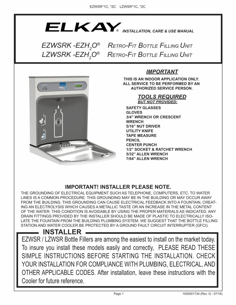
WATER COOLER PREPARATION1) Remove lower front panel of watercooler by removing the four (4) screws from the bottom of cooler. (See Fig. 1) NOTE: For Two Level Models the Bottle Filling Unit can be mounted to the higher or lower unit. Both lower front panels and basin assemblies will need to be removed.1a) For units with model no’s. ending with 1, 1A, 2 or 3 these units will need to be removed from the wall in order to remove the basin assembly(s).2) Power OFF circuit that the water cooler is connected to by switching the circuit breaker to the “OFF” position or by removing the fuse to the circuit. Remove the water cooler plug from the outlet and shut off water supply.3) Remove Basin Assembly by loosening four (4) screws two on each side of cooler as shown in Fig. 8. Disconnect water line “A” from bubbler at the evaporator tank (See Fig. 6). NOTE: When disconnecting water lines use a container to catch any water running out of the lines. Disconnect basin assembly from drain trap. Lift basin assembly straight up to remove, and disconnect two wires from push bar switches. (Note: This will allow easier assembly of water filter to unit and pressurization of the unit.)5a) For units referenced in step “1a”. Remove Basin Assembly by loosening four (4) screws two on each side of cooler as shown in Fig. 8. Remove 2 screws from top back of unit to remove the “L” bracket. Remove 1 screw from left side of cross brace in front of unit that retains the drain support. Disconnect water line “A” from regulator at the evaporator tank (See Fig. 6B). NOTE: When disconnecting water lines use a container to catch any water running out of the lines. Disconnect basin assembly from drain trap. Lift basin assembly straight up to remove, and disconnect two wires from push bar switches. (Note: This will allow easier assembly of water filter to unit and pressurization of the unit.) EWF3000 WATERSENTRY PLUS FILTER INSTALLATIONNOTICE: Do not use with water that is microbiologically unsafe or of un-known quality without adequate disinfection before or after the system.1) These filter kits must be installed in compliance with all state and local laws and regulations governing the installation and use of this product. Maximum inlet water temperature 100°F (38°C).2) See filter instructions for filter assembly. Insert 3/8” elbow fitting into the inlet side of filter head, insert 1/4” poly tube or 1/4” x 90° elbow into outlet side of filter head prior to mounting the filter head assembly into the cooler.3) Mount filter head as shown in Fig. 9, using the filter mounting bracket and screws supplied. For Two-Level units the filter must be mounted to the L.H. non-refrigerated unit at the same location as shown in Fig. 9. PRESSURIZATION OF WATER SYSTEMNOTE: This procedure MUST be performed on ALL SINGLE EZ WATER COOLERS or the bottle filling unit WILL NOT perform properly!1) Remove water inlet (B) and outlet (C) from solenoid valve (See Fig. 6 or 6B). NOTE: When disconnecting water lines use a container to catch any water run-ning out of the lines.2) CAUTION: If supply pressure will ever exceed 100 psi, install a pressure regulator to limit the inlet pressure to the filter to 100 psi or below. DO NOT ATTACH HOT WATER LINE TO FILTER. To make connections on the filter head, loosen locknut. Push the tube end past both o-rings to a positive stop in the filter head recess - approx. 1”, locknut may have to be backed out a little more. Screw the locknut hand tight to seal (See Fig. 10). Ends of tubing must be cut square and free of burrs and sharp ends that could cut or nick the o-rings.3) Connect the outlet of the filter to the inlet of the evaporator using the 1/4” O.D. poly tubing and 1/4” union supplied (See Fig. 7 or 7B).4) Cut a 12” long piece of poly tube (be sure to insulate poly tube with supplied insulation tubing) and insert one end into the outlet side of the evaporator “D” (See Fig. 7 or 7B), connect Tee to other end of tube.5) Cut a 12” long piece of poly tube (be sure to insulate poly tube with supplied insulation tubing) and insert into the Tee and the other end into the inlet side of the solenoid valve “E” (See fig. 7 or 7B).
Fig. 1LOWER COVER
SCREWS

Page 3 1000001734 (Rev. G - 07/16)
EZWSR*1C, *2C LZWSR*1C, *2C
17 7
/8"
454m
m
7"17
8mm
7"17
8mm
7/16
" X 3
/4"
11m
m X
19m
m
OBRO
UND
HOLE
S(6
)
15"
381m
m 2 7/
8"73
mm
2"51
mm
51 9
/16"
1310
mm
34 5
/16"
872m
m
24 1
/2"
622m
m 22 1
5/16
"58
3mm
19 7
/16"
494m
m
21 7
/8"
556m
m19
"48
3mm
28 1
3/16
"73
2mm
2"51
mm
17 7
/16"
443m
m13
15/
16"
354m
m
7"17
8mm
7"17
8mm
5 3/
4"14
6mm
2"51
mm
FINI
SHED
FLO
OR
6 3/
8"16
2mm
6 3/
8"16
2mm
‰
‰
2"51
mm 7/8"
22m
m
E
E
A(A
LT. L
OCAT
ION) F
DPR
EFER
RED
LOCA
TION
D (A
LT. L
OCAT
ION)
9/32
" Ø7m
m Ø
HOLE
S12
BA
PREF
ERRE
DLO
CATI
ON
12 1
/2"
318m
m3"
77m
m
1 7/
16"
37m
m
C
8 1/1
6"20
5mm
18 7
/8"
479m
m
3 9/
16"
90m
m
19"
483m
m
HANG
ER B
RACK
ET
32 7
/8"
835m
mOR
IFIC
EHE
IGHT 31
5/1
6"79
6mm
RIM
HEIG
HT
38 3
/8"
975m
mOR
IFIC
EHE
IGHT 36
13/
16"
936m
mRI
MHE
IGHT
OPTI
ONAL
FIL
TER
FILT
ER
6 3/
8"16
2mm
6 3/
8"16
2mm
18 3
/8"
467m
m
27"
686m
mAD
ARE
QUIR
EMEN
T
F3
7/8"
98m
m
ACTI
VATI
ON S
ENSO
R
38 1
/2"
979m
m
LEG
END
/LEY
END
A/L
ÉGEN
DE
A =
REC
OM
MEN
DED
WAT
ER S
UPP
LY L
OC
ATIO
N 3
/8 O
.D. U
NPL
ATED
CO
PPER
TU
BE
CO
NN
ECT
STU
B W
ITH
SH
UT
OFF
(BY
OTH
ERS)
3 IN
. (76
mm
) M
AXI
MU
M O
UT
FRO
M W
ALL
L
a U
BIC
AC
ION
3/8
O R
EC
OM
EN
DA
DA
de A
BA
STE
CIM
IEN
TO D
E A
GU
A. D
. El T
UB
O d
el C
OB
RE
de
UN
PLA
TED
CO
NE
CTA
TA
LON
AR
IO C
ON
APA
GO
(P
OR
OTR
OS
) 3 e
n. (7
6 M
m) e
l MA
XIM
O F
UE
RA
DE
PA
RE
D
L
’O.D
de
3/8
d’E
MP
LAC
EM
EN
T D
E P
RO
VIS
ION
D’E
AU
RE
CO
MM
AN
DE
. LE
TU
BE
DE
CU
IVR
E D
E U
NP
LATE
D C
ON
NE
CTE
STU
B A
VE
C E
TEIN
T (P
AR
LE
S A
UTR
ES
) 3 d
ans.
(76
mm
) le
MA
XIM
UM
HO
RS
DU
MU
RB
= R
ECO
MM
END
ED L
OC
ATIO
N F
OR
WA
STE
OU
TLET
1-1
/2”
O.D
. D
RA
IN S
TUB
2 IN
. OU
T FR
OM
WA
LLU
BIC
AC
IÓN
RE
CO
ME
ND
AD
A PA
RA
EL
DR
EN
AJE
DE
SA
LID
A D
E A
GU
A, D
E 1
-1/2
” DE
DIÁ
ME
TRO
. El T
ALO
NA
RIO
2 F
UE
RA
DE
PA
RE
DE
MP
LAC
EM
EN
T R
EC
OM
MA
ND
É P
OU
R L
E D
RA
IN D
E D
.E. 1
-1/2
” DE
SO
RTI
E D
’EA
U. S
TUB
2 H
OR
S D
U M
UR
C =
1-1
/2”
TRA
P N
OT
FUR
NIS
HED
PU
RG
AD
OR
DE
1-1
/2” N
O P
RO
PO
RC
ION
AD
OS
IPH
ON
1-1
/2” N
ON
FO
UR
NI
D =
ELE
CTR
ICA
L SU
PPLY
(3) W
IRE
REC
ESSE
D B
OX*
*C
AJA
RE
CE
SIV
A D
E A
LAM
BR
ES
(3) D
E S
UM
INIS
TRO
ELÉ
CTR
ICO
BO
ÎTE
EN
CA
STR
ÉE
D’A
LIM
EN
TATI
ON
ÉLE
CTR
IQU
E (3
) FIL
S
LEG
END
/LEY
END
A/L
ÉGEN
DE
D =
ELE
CTR
ICA
L SU
PPLY
(3) W
IRE
REC
ESSE
D B
OX*
*C
AJA
RE
CE
SIV
A D
E A
LAM
BR
ES
(3) D
E S
UM
INIS
TRO
ELÉ
CTR
ICO
BO
ÎTE
EN
CA
STR
ÉE
D’A
LIM
EN
TATI
ON
ÉLE
CTR
IQU
E (3
) FIL
SE
= IN
SUR
E PR
OPE
R V
ENTI
LATI
ON
BY
MA
INTA
ININ
G 6
” (1
52 m
m) (
MIN
.) C
LEA
RA
NC
E FR
OM
CA
BIN
ET L
OU
VER
S TO
WA
LL.
AS
EG
UR
E U
NA
VE
NTI
LAC
IÓN
AD
EC
UA
DA
MA
NTE
NIE
ND
O U
N E
SPA
CIO
E 6
” (15
2 m
m) (
MÍN
.) D
E H
OLG
UR
A E
NTR
E L
A R
EJI
LLA
DE
VE
NTI
LAC
IÓN
DE
L M
UE
BLE
Y L
A PA
RE
D.
AS
SU
RE
Z-V
OU
S U
NE
BO
NN
E V
EN
TILA
TIO
N E
N G
AR
DA
NT
6” (1
52 m
m) (
MIN
.) E
NTR
E L
ES
ÉV
EN
TS D
E L
’EN
CE
INTE
ET
LE M
UR
.F
= 7/
16 B
OLT
HO
LES
FOR
FA
STEN
ING
UN
IT T
O W
ALL
AG
UJE
RO
S D
E L
AS
TU
ER
CA
S D
E 7
/16
PAR
A S
UJE
TAR
LA
UN
IDA
D A
LA
PAR
ED
TRO
US
D’É
CR
OU
S 7
/16
PO
UR
FIX
ER
L’A
PPA
RE
IL A
U M
UR
**N
EW IN
STA
LLAT
ION
S M
UST
USE
GR
OU
ND
FA
ULT
CIR
CU
IT IN
TER
RU
PTER
(GFC
I)**
Las
nuev
as in
stal
acio
nes
debe
n ut
iliza
r el i
nter
rupt
or d
e ci
rcui
to d
e tie
rra
de la
ave
ría (G
FCI)
**Le
s no
uvel
les
inst
alla
tions
doi
vent
em
ploy
er l’
inte
rrup
teur
de
circ
uit m
oulu
de
défa
ut (G
FCI)
RED
UC
E H
EIG
HT
BY
3 IN
CH
ES F
OR
INST
ALL
ATIO
N O
F C
HIL
DR
EN’S
AD
A C
OO
LER
STA
ND
AR
D R
OU
GH
-IN F
OR
LEF
T-H
AN
D H
IGH
, BO
TTLE
FIL
LER
LO
W M
OD
ELS
Fig. 2
Page 4
EZWSR*1C, *2C LZWSR*1C, *2C
1000001734 (Rev. G - 07/16)
17 7
/8"
454m
m
7"17
8mm
7"17
8mm
7/16
" X 3
/4"
11m
m X
19m
m
OBRO
UND
HOL
ES(6
)
15"
381m
m
2 7/
8"73
mm
2"51
mm
51 9
/16"
1310
mm
28 1
3/16
"73
2mm
19"
483m
m17
7/16
"44
3mm
13 1
5/16
"35
4mm
24 1
/2"
622m
m34 5
/16"
872m
m
2"51
mm
22 1
5/16
"58
3mm
19 7
/16"
494m
m
7"17
8mm
7"17
8mm
5 3/
4"14
6mm
2"51
mm
FINI
SHED
FLO
OR
18 3
/8"
467m
m
6 3/
8"16
2mm
6 3/
8"16
2mm
6 3/
8"16
2mm
‰
‰
6 3/
8"16
2mm
2"51
mm 7/8"
22m
m
E
E
A(A
LT. L
OCAT
ION)
F
DPR
EFER
RED
LOCA
TION
D (A
LT. L
OCAT
ION)
9/32
" Ø7m
m Ø
HOLE
S12
A PR
EFER
RED
LOCA
TION
12 1
/2"
318m
m3"
76m
m
C
3 9/
16"
90m
m
19"
483m
m
HANG
ER B
RACK
ET
31 5
/16"
796m
mRI
MHE
IGHT
38 3
/8"
975m
mOR
IFIC
EHE
IGHT 36
13/
16"
936m
mRI
MHE
IGHT
OPTI
ONAL
FIL
TER
32 7
/8"
835m
mOR
IFIC
EHE
IGHT
1 7/
16"
37m
m
8 1/1
6"20
5mm FILT
ER
B
18 7
/8"
479m
m
27"
686m
mAD
ARE
QUIR
EMEN
T
F21
7/8
"55
6mm
3 7/
8"98
mm
ACTI
VATI
ON S
ENSO
R
38 1
/2"
979m
m
LEG
END
/LEY
END
A/L
ÉGEN
DE
A =
REC
OM
MEN
DED
WAT
ER S
UPP
LY L
OC
ATIO
N 3
/8 O
.D. U
NPL
ATED
CO
PPER
TU
BE
CO
NN
ECT
STU
B W
ITH
SH
UT
OFF
(BY
OTH
ERS)
3 IN
. (76
mm
) M
AXI
MU
M O
UT
FRO
M W
ALL
L
a U
BIC
AC
ION
3/8
O R
EC
OM
EN
DA
DA
de A
BA
STE
CIM
IEN
TO D
E A
GU
A. D
. El T
UB
O d
el C
OB
RE
de
UN
PLA
TED
CO
NE
CTA
TA
LON
AR
IO C
ON
APA
GO
(P
OR
OTR
OS
) 3 e
n. (7
6 M
m) e
l MA
XIM
O F
UE
RA
DE
PA
RE
D
L
’O.D
de
3/8
d’E
MP
LAC
EM
EN
T D
E P
RO
VIS
ION
D’E
AU
RE
CO
MM
AN
DE
. LE
TU
BE
DE
CU
IVR
E D
E U
NP
LATE
D C
ON
NE
CTE
STU
B A
VE
C E
TEIN
T (P
AR
LE
S A
UTR
ES
) 3 d
ans.
(76
mm
) le
MA
XIM
UM
HO
RS
DU
MU
RB
= R
ECO
MM
END
ED L
OC
ATIO
N F
OR
WA
STE
OU
TLET
1-1
/2”
O.D
. D
RA
IN S
TUB
2 IN
. OU
T FR
OM
WA
LL U
BIC
AC
IÓN
RE
CO
ME
ND
AD
A PA
RA
EL
DR
EN
AJE
DE
SA
LID
A D
E A
GU
A, D
E 1
-1/2
” DE
DIÁ
ME
TRO
. El T
ALO
NA
RIO
2 F
UE
RA
DE
PA
RE
DE
MP
LAC
EM
EN
T R
EC
OM
MA
ND
É P
OU
R L
E D
RA
IN D
E D
.E. 1
-1/2
” DE
SO
RTI
E D
’EA
U. S
TUB
2 H
OR
S D
U M
UR
C =
1-1
/2”
TRA
P N
OT
FUR
NIS
HED
PU
RG
AD
OR
DE
1-1
/2” N
O P
RO
PO
RC
ION
AD
OS
IPH
ON
1-1
/2” N
ON
FO
UR
NI
D =
ELE
CTR
ICA
L SU
PPLY
(3) W
IRE
REC
ESSE
D B
OX*
*C
AJA
RE
CE
SIV
A D
E A
LAM
BR
ES
(3) D
E S
UM
INIS
TRO
ELÉ
CTR
ICO
BO
ÎTE
EN
CA
STR
ÉE
D’A
LIM
EN
TATI
ON
ÉLE
CTR
IQU
E (3
) FIL
S
LEG
END
/LEY
END
A/L
ÉGEN
DE
D =
ELE
CTR
ICA
L SU
PPLY
(3) W
IRE
REC
ESSE
D B
OX*
*C
AJA
RE
CE
SIV
A D
E A
LAM
BR
ES
(3) D
E S
UM
INIS
TRO
ELÉ
CTR
ICO
BO
ÎTE
EN
CA
STR
ÉE
D’A
LIM
EN
TATI
ON
ÉLE
CTR
IQU
E (3
) FIL
SE
= IN
SUR
E PR
OPE
R V
ENTI
LATI
ON
BY
MA
INTA
ININ
G 6
” (1
52 m
m) (
MIN
.) C
LEA
RA
NC
E FR
OM
CA
BIN
ET L
OU
VER
S TO
WA
LL.
AS
EG
UR
E U
NA
VE
NTI
LAC
IÓN
AD
EC
UA
DA
MA
NTE
NIE
ND
O U
N E
SPA
CIO
E 6
” (15
2 m
m) (
MÍN
.) D
E H
OLG
UR
A E
NTR
E L
A R
EJI
LLA
DE
VE
NTI
LAC
IÓN
DE
L M
UE
BLE
Y L
A PA
RE
D.
AS
SU
RE
Z-V
OU
S U
NE
BO
NN
E V
EN
TILA
TIO
N E
N G
AR
DA
NT
6” (1
52 m
m) (
MIN
.) E
NTR
E L
ES
ÉV
EN
TS D
E L
’EN
CE
INTE
ET
LE M
UR
.F
= 7/
16 B
OLT
HO
LES
FOR
FA
STEN
ING
UN
IT T
O W
ALL
AG
UJE
RO
S D
E L
AS
TU
ER
CA
S D
E 7
/16
PAR
A S
UJE
TAR
LA
UN
IDA
D A
LA
PAR
ED
TRO
US
D’É
CR
OU
S 7
/16
PO
UR
FIX
ER
L’A
PPA
RE
IL A
U M
UR
**N
EW IN
STA
LLAT
ION
S M
UST
USE
GR
OU
ND
FA
ULT
CIR
CU
IT IN
TER
RU
PTER
(GFC
I)**
Las
nuev
as in
stal
acio
nes
debe
n ut
iliza
r el i
nter
rupt
or d
e ci
rcui
to d
e tie
rra
de la
ave
ría (G
FCI)
**Le
s no
uvel
les
inst
alla
tions
doi
vent
em
ploy
er l’
inte
rrup
teur
de
circ
uit m
oulu
de
défa
ut (G
FCI)
RED
UC
E H
EIG
HT
BY
3 IN
CH
ES F
OR
INST
ALL
ATIO
N O
F C
HIL
DR
EN’S
AD
A C
OO
LER
ALT
ERN
ATE
RO
UG
H-IN
FO
R R
IGH
T-H
AN
D H
IGH
, BO
TTLE
FIL
LER
LO
W M
OD
ELS
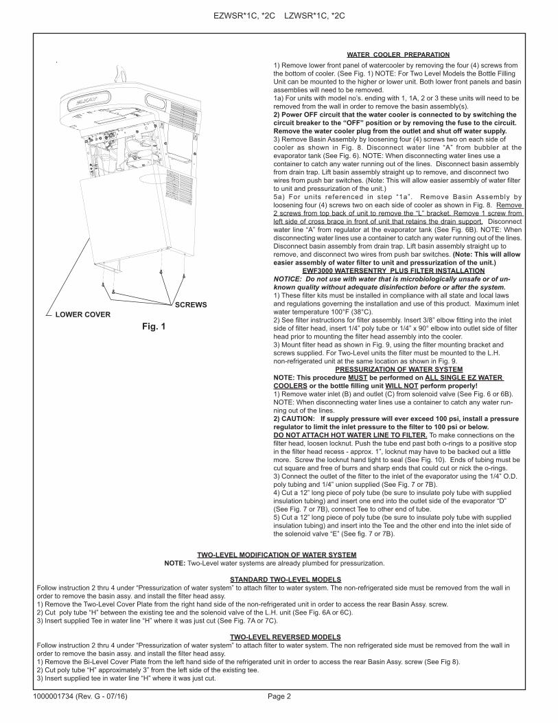
Fig. 3
REQ
UIR
ES B
ASI
N A
SSY
CH
AN
GE.
SEE
PA
GES
11
FOR
INST
RU
CTI
ON
S

Page 5 1000001734 (Rev. G - 07/16)
EZWSR*1C, *2C LZWSR*1C, *2C
7/16
" X 3
/4"
11m
m X
19m
m
OBRO
UND
HOLE
S(6
)
2"51
mm
28 1
3/16
"73
2mm
19"
483m
m17
7/16
"44
3mm
13 1
5/16
"35
4mm
24 1
/2"
622m
m34 5
/16"
872m
m
2"51
mm
22 1
5/16
"58
3mm
19 7
/16"
494m
m
7"17
8mm
7"1 7
8mm
5 3/
4"14
6mm
2"51
mm
FINI
SHED
FLO
OR
6 3/
8"16
2 mm
6 3/
8"16
2mm
‰
‰
2"51
mm 7/8"
22m
m
E
E
A(A
LT. L
OCAT
ION)
F
DPR
EFER
RED
LOCA
TION
D (A
LT. L
OCAT
ION)
9/32
" Ø7m
m Ø
H OLE
S12
A PR
EFER
RED
LOCA
TION
C
HANG
ER B
RACK
ET
OPTI
ONAL
FIL
TER
FILT
ER
B
12 1
/2"
318m
m
1 7/
16"
37m
m
3"77
mm
18 7
/ 8"
479m
m
3 9 /
16"
90m
m
19"
483m
m
8 1/
16"
205m
m
27"
686m
mAD
ARE
QUIR
EMEN
T
31 5
/16"
796m
mRI
MHE
IGHT
32 7
/8"
835m
mOR
IFIC
E HE
IGHT
36 1
3/16
"93
6mm
RIM
HEIG
HT
38 3
/8"
975m
mOR
FICE
HEIG
HT
17 7
/ 8"
454m
m
7"1 7
8mm
7 "17
8mm
6 3/
8"16
2mm
6 3/
8"16
2mm
18 3
/8"
4 67m
m
15"
381m
m
2 7/
8"73
mm
F
21 7
/8"
556m
m
3 7/
8"98
mm
57 1
/16"
1450
mm
ACTI
VATI
ON S
ENSO
R
44"
1118
mm
LEG
END
/LEY
END
A/L
ÉGEN
DE
A =
REC
OM
MEN
DED
WAT
ER S
UPP
LY L
OC
ATIO
N 3
/8 O
.D. U
NPL
ATED
CO
PPER
TU
BE
CO
NN
ECT
STU
B W
ITH
SH
UT
OFF
(BY
OTH
ERS)
3 IN
. (76
mm
) M
AXI
MU
M O
UT
FRO
M W
ALL
L
a U
BIC
AC
ION
3/8
O R
EC
OM
EN
DA
DA
de A
BA
STE
CIM
IEN
TO D
E A
GU
A. D
. El T
UB
O d
el C
OB
RE
de
UN
PLA
TED
CO
NE
CTA
TA
LON
AR
IO C
ON
APA
GO
(P
OR
OTR
OS
) 3 e
n. (7
6 M
m) e
l MA
XIM
O F
UE
RA
DE
PA
RE
D
L
’O.D
de
3/8
d’E
MP
LAC
EM
EN
T D
E P
RO
VIS
ION
D’E
AU
RE
CO
MM
AN
DE
. LE
TU
BE
DE
CU
IVR
E D
E U
NP
LATE
D C
ON
NE
CTE
STU
B A
VE
C E
TEIN
T (P
AR
LE
S A
UTR
ES
) 3 d
ans.
(76
mm
) le
MA
XIM
UM
HO
RS
DU
MU
RB
= R
ECO
MM
END
ED L
OC
ATIO
N F
OR
WA
STE
OU
TLET
1-1
/2”
O.D
. D
RA
IN S
TUB
2 IN
. OU
T FR
OM
WA
LL U
BIC
AC
IÓN
RE
CO
ME
ND
AD
A PA
RA
EL
DR
EN
AJE
DE
SA
LID
A D
E A
GU
A, D
E 1
-1/2
” DE
DIÁ
ME
TRO
. El T
ALO
NA
RIO
2 F
UE
RA
DE
PA
RE
D E
MP
LAC
EM
EN
T R
EC
OM
MA
ND
É P
OU
R L
E D
RA
IN D
E D
.E. 1
-1/2
” DE
SO
RTI
E D
’EA
U. S
TUB
2 H
OR
S D
U M
UR
C =
1-1
/2”
TRA
P N
OT
FUR
NIS
HED
PU
RG
AD
OR
DE
1-1
/2” N
O P
RO
PO
RC
ION
AD
O S
IPH
ON
1-1
/2” N
ON
FO
UR
NI
D =
ELE
CTR
ICA
L SU
PPLY
(3) W
IRE
REC
ESSE
D B
OX*
*C
AJA
RE
CE
SIV
A D
E A
LAM
BR
ES
(3) D
E S
UM
INIS
TRO
ELÉ
CTR
ICO
BO
ÎTE
EN
CA
STR
ÉE
D’A
LIM
EN
TATI
ON
ÉLE
CTR
IQU
E (3
) FIL
S
LEG
END
/LEY
END
A/L
ÉGEN
DE
D =
ELE
CTR
ICA
L SU
PPLY
(3) W
IRE
REC
ESSE
D B
OX*
*C
AJA
RE
CE
SIV
A D
E A
LAM
BR
ES
(3) D
E S
UM
INIS
TRO
ELÉ
CTR
ICO
BO
ÎTE
EN
CA
STR
ÉE
D’A
LIM
EN
TATI
ON
ÉLE
CTR
IQU
E (3
) FIL
SE
= IN
SUR
E PR
OPE
R V
ENTI
LATI
ON
BY
MA
INTA
ININ
G 6
” (1
52 m
m) (
MIN
.) C
LEA
RA
NC
E FR
OM
CA
BIN
ET L
OU
VER
S TO
WA
LL.
AS
EG
UR
E U
NA
VE
NTI
LAC
IÓN
AD
EC
UA
DA
MA
NTE
NIE
ND
O U
N E
SPA
CIO
E 6
” (15
2 m
m) (
MÍN
.) D
E H
OLG
UR
A E
NTR
E L
A R
EJI
LLA
DE
VE
NTI
LAC
IÓN
DE
L M
UE
BLE
Y L
A PA
RE
D.
AS
SU
RE
Z-V
OU
S U
NE
BO
NN
E V
EN
TILA
TIO
N E
N G
AR
DA
NT
6” (1
52 m
m) (
MIN
.) E
NTR
E L
ES
ÉV
EN
TS D
E L
’EN
CE
INTE
ET
LE M
UR
.F
= 7/
16 B
OLT
HO
LES
FOR
FA
STEN
ING
UN
IT T
O W
ALL
AG
UJE
RO
S D
E L
AS
TU
ER
CA
S D
E 7
/16
PAR
A S
UJE
TAR
LA
UN
IDA
D A
LA
PAR
ED
TRO
US
D’É
CR
OU
S 7
/16
PO
UR
FIX
ER
L’A
PPA
RE
IL A
U M
UR
**N
EW IN
STA
LLAT
ION
S M
UST
USE
GR
OU
ND
FA
ULT
CIR
CU
IT IN
TER
RU
PTER
(GFC
I)**
Las
nuev
as in
stal
acio
nes
debe
n ut
iliza
r el i
nter
rupt
or d
e ci
rcui
to d
e tie
rra
de la
ave
ría (G
FCI)
**Le
s no
uvel
les
inst
alla
tions
doi
vent
em
ploy
er l’
inte
rrup
teur
de
circ
uit m
oulu
de
défa
ut (G
FCI)
RED
UC
E H
EIG
HT
BY
3 IN
CH
ES F
OR
INST
ALL
ATIO
N O
F C
HIL
DR
EN’S
AD
A C
OO
LER
ALT
ERN
ATE
RO
UG
H-IN
FO
R R
IGH
T-H
AN
D H
IGH
, BO
TTLE
FIL
LER
HIG
H M
OD
ELS
Fig. 4

Page 6
EZWSR*1C, *2C LZWSR*1C, *2C
1000001734 (Rev. G - 07/16)
17 7
/8"
454m
m
7"17
8mm
7"17
8mm
7/16
" X 3
/4"
11m
m X
19m
m
OBRO
UND
HOLE
S(6
)
15"
381m
m
2 7/
8"73
mm
2"51
mm
57 1
/16"
1450
mm
34 5
/16"
872m
m
24 1
/2"
622m
m 22 1
5/16
"58
3mm
19 7
/16"
494m
m
21 7
/8"
556m
m19
"48
3mm
28 1
3/16
"73
2mm
2"51
mm
17 7
/16"
443m
m13
15/
16"
354m
m
7"17
8mm
7"17
8mm
5 3/
4"14
6mm
2"51
mm
FINI
SHED
FLO
OR
18 3
/8"
467m
m
6 3/
8"16
2mm
6 3/
8"16
2mm
6 3/
8"16
2mm
‰
‰
6 3/
8"16
2mm
2"51
mm 7/8"
22m
m
E
E
A(A
LT. L
OCAT
ION) F
DPR
EFER
RED
LOCA
TION
D (A
LT. L
OCAT
ION)
9/32
" Ø7m
m Ø
HOLE
S12
BA
PREF
ERRE
DLO
CATI
ON
12 1
/2"
318m
m3"
77m
m
1 7/
16"
37m
m
C
8 1/1
6"20
5mm
18 7
/8"
479m
m
3 9/
16"
90m
m
19"
483m
m
HANG
ER B
RACK
ET
38 3
/8"
975m
mOR
IFIC
EHE
IGHT 36
13/
16"
935m
mRI
MHE
IGHT 32
7/8
"83
5mm
ORIF
ICE
HEIG
HT 31 5
/16"
796m
mRI
MHE
IGHT
FIL
TER
FILT
ER
27"
686m
mAD
ARE
QUIR
EMEN
T
F
3 7/
8"98
mm
ACTI
VATI
ON S
ENSO
R
44"
1118
mm
LEG
END
/LEY
END
A/L
ÉGEN
DE
A =
REC
OM
MEN
DED
WAT
ER S
UPP
LY L
OC
ATIO
N 3
/8 O
.D. U
NPL
ATED
CO
PPER
TU
BE
CO
NN
ECT
STU
B W
ITH
SH
UT
OFF
(BY
OTH
ERS)
3 IN
. (76
mm
) M
AXI
MU
M O
UT
FRO
M W
ALL
L
a U
BIC
AC
ION
3/8
O R
EC
OM
EN
DA
DA
de A
BA
STE
CIM
IEN
TO D
E A
GU
A. D
. El T
UB
O d
el C
OB
RE
de
UN
PLA
TED
CO
NE
CTA
TA
LON
AR
IO C
ON
APA
GO
(P
OR
OTR
OS
) 3 e
n. (7
6 M
m) e
l MA
XIM
O F
UE
RA
DE
PA
RE
D
L
’O.D
de
3/8
d’E
MP
LAC
EM
EN
T D
E P
RO
VIS
ION
D’E
AU
RE
CO
MM
AN
DE
. LE
TU
BE
DE
CU
IVR
E D
E U
NP
LATE
D C
ON
NE
CTE
STU
B A
VE
C E
TEIN
T (P
AR
LE
S A
UTR
ES
) 3 d
ans.
(76
mm
) le
MA
XIM
UM
HO
RS
DU
MU
RB
= R
ECO
MM
END
ED L
OC
ATIO
N F
OR
WA
STE
OU
TLET
1-1
/2”
O.D
. D
RA
IN S
TUB
2 IN
. OU
T FR
OM
WA
LL U
BIC
AC
IÓN
RE
CO
ME
ND
AD
A PA
RA
EL
DR
EN
AJE
DE
SA
LID
A D
E A
GU
A, D
E 1
-1/2
” DE
DIÁ
ME
TRO
. El T
ALO
NA
RIO
2 F
UE
RA
DE
PA
RE
DE
MP
LAC
EM
EN
T R
EC
OM
MA
ND
É P
OU
R L
E D
RA
IN D
E D
.E. 1
-1/2
” DE
SO
RTI
E D
’EA
U. S
TUB
2 H
OR
S D
U M
UR
C =
1-1
/2”
TRA
P N
OT
FUR
NIS
HED
PU
RG
AD
OR
DE
1-1
/2” N
O P
RO
PO
RC
ION
AD
OS
IPH
ON
1-1
/2” N
ON
FO
UR
NI
D =
ELE
CTR
ICA
L SU
PPLY
(3) W
IRE
REC
ESSE
D B
OX*
*C
AJA
RE
CE
SIV
A D
E A
LAM
BR
ES
(3) D
E S
UM
INIS
TRO
ELÉ
CTR
ICO
BO
ÎTE
EN
CA
STR
ÉE
D’A
LIM
EN
TATI
ON
ÉLE
CTR
IQU
E (3
) FIL
S
LEG
END
/LEY
END
A/L
ÉGEN
DE
D =
ELE
CTR
ICA
L SU
PPLY
(3) W
IRE
REC
ESSE
D B
OX*
*C
AJA
RE
CE
SIV
A D
E A
LAM
BR
ES
(3) D
E S
UM
INIS
TRO
ELÉ
CTR
ICO
BO
ÎTE
EN
CA
STR
ÉE
D’A
LIM
EN
TATI
ON
ÉLE
CTR
IQU
E (3
) FIL
SE
= IN
SUR
E PR
OPE
R V
ENTI
LATI
ON
BY
MA
INTA
ININ
G 6
” (1
52 m
m) (
MIN
.) C
LEA
RA
NC
E FR
OM
CA
BIN
ET L
OU
VER
S TO
WA
LL.
AS
EG
UR
E U
NA
VE
NTI
LAC
IÓN
AD
EC
UA
DA
MA
NTE
NIE
ND
O U
N E
SPA
CIO
E 6
” (15
2 m
m) (
MÍN
.) D
E H
OLG
UR
A E
NTR
E L
A R
EJI
LLA
DE
VE
NTI
LAC
IÓN
DE
L M
UE
BLE
Y L
A PA
RE
D.
AS
SU
RE
Z-V
OU
S U
NE
BO
NN
E V
EN
TILA
TIO
N E
N G
AR
DA
NT
6” (1
52 m
m) (
MIN
.) E
NTR
E L
ES
ÉV
EN
TS D
E L
’EN
CE
INTE
ET
LE M
UR
.F
= 7/
16 B
OLT
HO
LES
FOR
FA
STEN
ING
UN
IT T
O W
ALL
AG
UJE
RO
S D
E L
AS
TU
ER
CA
S D
E 7
/16
PAR
A S
UJE
TAR
LA
UN
IDA
D A
LA
PAR
ED
TRO
US
D’É
CR
OU
S 7
/16
PO
UR
FIX
ER
L’A
PPA
RE
IL A
U M
UR
**N
EW IN
STA
LLAT
ION
S M
UST
USE
GR
OU
ND
FA
ULT
CIR
CU
IT IN
TER
RU
PTER
(GFC
I)**
Las
nuev
as in
stal
acio
nes
debe
n ut
iliza
r el i
nter
rupt
or d
e ci
rcui
to d
e tie
rra
de la
ave
ría (G
FCI)
**Le
s no
uvel
les
inst
alla
tions
doi
vent
em
ploy
er l’
inte
rrup
teur
de
circ
uit m
oulu
de
défa
ut (G
FCI)
RED
UC
E H
EIG
HT
BY
3 IN
CH
ES F
OR
INST
ALL
ATIO
N O
F C
HIL
DR
EN’S
AD
A C
OO
LER
ALT
ERN
ATE
RO
UG
H-IN
FO
R L
EFT-
HA
ND
HIG
H, B
OTT
LE F
ILLE
R H
IGH
MO
DEL
S
Fig. 5
REQ
UIR
ES B
ASI
N A
SSY
CH
AN
GE.
SEE
PA
GES
11
FOR
INST
RU
CTI
ON
S

Page 7 1000001734 (Rev. G - 07/16)
EZWSR*1C, *2C LZWSR*1C, *2C
Fig. 6
EZ Non-Pressurized Plumbing Diagram
Evaporator
Bubbler
Solenoid ValveWater Inlet B
C
A
EZ Plumbing Diagram after Pressurization Modifications
Bubbler
3/8” Water Line from Bottle Filling Unit
Evaporator
Solenoid Valve
3/8” Water Inlet
Fig. 7
3/8” To 1/4” Union
Tube Insulation
Tube Insulation
Tee
Fig. 6A
Standard EZ Two Level Pressurized Plumbing Diagram
R.H. Refrig. unitL.H. Non-Refrig unit
EvaporatorBubbler
Water InletBubbler
HSolenoid Valve Solenoid Valve
E
F
G
D
Fig. 7A
EZ Two Level Plumbing Diagramafter Bottle Filler
Water Line Addition
R.H. Refrig. unitL.H. Non-Refrig unit
Evaporator
Bubbler
Solenoid Valve
BubblerWater Inlet
H
Solenoid Valve
Tee

Page 8
EZWSR*1C, *2C LZWSR*1C, *2C
1000001734 (Rev. G - 07/16)
Fig. 6B
EZ Non-Pressurized Plumbing Diagram
Plumbing Diagrams for EZ Coolers w/model no’s ending with 1, 1A, 2, & 3
Evaporator
Bubbler
Solenoid Valve
Water Inlet
B C
A
Regulator
3/8” Water Line from Bottle Filling Unit
EZ Plumbing Diagram after Pressurization Modifications
Bubbler Evaporator
Solenoid Valve
Tee
3/8” Water Inlet
D
EF
Fig. 7B
Regulator
Tube Insulation
3/8” To 1/4” Union
Fig. 6C
Standard EZ Two Level Pressurized Plumbing Diagram
R.H. Refrig. unitL.H. Non-Refrig unit
EvaporatorBubbler
Water Inlet
Bubbler
H
Solenoid Valve
Solenoid Valve
RegulatorRegulator
EZ Two Level Plumbing Diagram afterBottle Filler Water Line Addition
Fig. 7C
Bubbler
Bubbler
Evaporator3/8” Water Inlet
Tee
3/8” Water Line from Bottle Filling Unit
H
Regulator
Solenoid Valve
Solenoid Valve
Regulator
R.H. Refrig. unitL.H. Non-Refrig unit
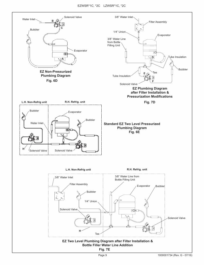
Page 9 1000001734 (Rev. G - 07/16)
EZWSR*1C, *2C LZWSR*1C, *2C
Fig. 6E
Standard EZ Two Level Pressurized Plumbing Diagram
EZ Two Level Plumbing Diagram after Filter Installation & Bottle Filler Water Line Addition
Fig. 7E
R.H. Refrig. unitL.H. Non-Refrig unit
EvaporatorBubbler
Water InletBubbler
H
R.H. Refrig. unitL.H. Non-Refrig unit
Fig. 6D
EZ Non-Pressurized Plumbing Diagram
Evaporator
Bubbler
Solenoid ValveWater Inlet B
C
A
EZ Plumbing Diagram after Filter Installation &
Pressurization Modifications
Bubbler
Filter Assembly
3/8” Water Line from Bottle Filling Unit
Evaporator
Solenoid Valve
Tee
3/8” Water Inlet
D
E
F
Fig. 7D
Solenoid Valve Solenoid Valve
1/4” Union
Tube Insulation
Tube Insulation
Bubbler
BubblerEvaporator
3/8” Water Inlet
Tee
3/8” Water Line from Bottle Filling Unit
H
Filter Assembly
1/4” Union
Solenoid Valve
Solenoid Valve

Page 10
EZWSR*1C, *2C LZWSR*1C, *2C
1000001734 (Rev. G - 07/16)
Fig. 6F
EZ Non-Pressurized Plumbing Diagram
Evaporator
Bubbler
Solenoid Valve
Water Inlet
BC
A
Plumbing Diagrams for EZ Coolers w/model no’s ending with 1, 1A, 2, & 3
Regulator
EZ Plumbing Diagram after Filter Installation &
Pressurization Modifications
Bubbler
3/8” Water Line from Bottle Filling Unit
Evaporator
Solenoid Valve
Tee
3/8” Water Inlet
DE
F
Fig. 7F
1/4” Union
Regulator
Fig. 6G
Standard EZ Two Level Pressurized Plumbing Diagram
R.H. Refrig. unitL.H. Non-Refrig unit
EvaporatorBubbler
Water Inlet
Bubbler
H
Solenoid Valve
Solenoid Valve
RegulatorRegulator
EZ Two Level Plumbing Diagram after Filter Installation &Bottle Filler Water Line Addition
Fig. 7G
Bubbler
BubblerEvaporator
3/8” Water Inlet
Tee
3/8” Water Line from Bottle Filling Unit
H
R.H. Refrig. unitL.H. Non-Refrig unit
Filter Assembly
1/4” Union
Solenoid Valve
Solenoid Valve
Regulator
Regulator
Tube Insulation
Page 11 1000001734 (Rev. G - 07/16)
EZWSR*1C, *2C LZWSR*1C, *2C
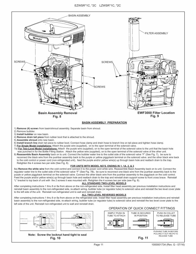
BASIN ASSEMBLY PREPARATION
1) Remove (4) screws from basin/shroud assembly. Separate basin from shroud.2) Remove bubbler.3) Install bubbler on new basin.4) Remove drain tail piece from rubber boot that is attached to the shroud.5) Assemble shroud onto new basin.6) Install branch line drain tail piece to rubber boot. Connect hose clamp and drain hose to branch line on tail piece and tighten hose clamp.7) For Single Model installations: Attach the purple wire (supplied), on to the open terminal of the solenoid valve.7a) For Two-Level Model installations: Attach the purple wire (supplied), on to the open terminal of the solenoid valve to the unit that the basin hole was punched in for the Bottle Filling Station. Attach the yellow wire (supplied), on to the open terminal of the solenoid valve of the other unit.8) Reassemble Basin Assembly back on to unit. Connect the bubbler water line to the outlet side of the solenoid valve “F” (See Fig. 7), be sure to reconnect the black wire from the pushbar assembly back to the purple or yellow piggyback terminal on the solenoid valve. and the other black wire back to the cold control or power cord (non-refrigerated unit), feed the purple and/or yellow wire(s) up through basin hole and reattach drain to the trap. Retighten the 4 screws two per side (See Fig. 8).
FOR UNITS WITH MODEL NO’S. ENDING IN 1, 1A, 2, & 38a) Remove the white wire from the cold control and connect it to the power cord white wire. Reassemble Basin Assembly back on to unit. Connect the regulator water line to the outlet side of the solenoid valve “F” (See Fig. 7B), be sure to reconnect one black wire from the pushbar assembly back to the purple or yellow piggyback terminal on the solenoid valve. Connect the other black wire from the pushbar assembly to the piggyback on the cold control. Feed the purple and/or yellow wire(s) up through basin hole and reattach drain to the trap and reinstall drain support screw to front cross brace. Reinstall “L” bracket to top back of unit with the 2 screws it was mounted with. Retighten the 4 screws two per side (see Fig. 8). ALL STANDARD TWO-LEVEL MODELSAfter completing instructions 1 thru 8 or 8a from above on the non-refrigerated side. Install filter head assembly per previous installation instructions and reinstall basin assembly to the non-refrigerated side, re-attach wiring, bubbler tube (or regulator tube) to solenoid valve and reinstall the two level cover plate to the left side of the unit. Reinstall non-refrigerated unit to wall and reinstall drain. ALL TWO-LEVEL REVERSED MODELSAfter completing instructions 1 thru 8 or 8a from above on the refrigerated side. Install filter head assembly per previous installation instructions and reinstall basin assembly to the non-refrigerated side, re-attach wiring, bubbler tube (or regulator tube) to solenoid valve and reinstall the two level cover plate to the left side of the unit. Reinstall non-refrigerated unit to wall and reinstall drain.
B CA
SIMPLY PUSH INTUBE TO ATTACH
TUBE IS SECUREDIN POSITION
PUSH IN COLLETTO RELEASE TUBE
OPERATION OF QUICK CONNECT FITTINGS
PUSHING TUBE IN BEFOREPULLING IT OUT HELPS TO
RELEASE TUBE
OPERATION OF QUICK CONNECT FITTINGSSIMPLY PUSH INTUBE TO ATTACH
TUBE IS SECURED IN POSITION
PUSH IN COLLETTO RELEASE TUBE
PUSHING TUBE IN BEFORE PULLING IT OUT HELPS TO
RELEASE TUBE
A B C
Fig. 8
SCREWS
SCREWS
BASIN ASSEMBLY
Fig. 9Basin Assembly Removal EWF3000 Filter Location
FILTER ASSEMBLY
SCREWS
Fig. 10 Note: Screw the locknut hand tight to seal
Fig. 11

Page 12
EZWSR*1C, *2C LZWSR*1C, *2C
1000001734 (Rev. G - 07/16)
WIRING DIAGRAM - NON REFRIGERATED SIDE WIRING DIAGRAM - REFRIGERATED SIDE
NOTE: UNITS PRODUCED 2008 AND BEFORE WILL NEED ADAPTERS TO SWITCH LINE AND NEUTRAL WIRES.
WIRING DIAGRAM - BOTTLE FILLER 115V
1
C
SFAN
1
WHT
5
2
6
3
M
3
2
GND
SMO
OTH
RIBB
ED
RELAY
OVERLOAD
COLDCONTROL
SOLENOIDVALVE
GRE
EN
BLK
GND
PURPLE ORYELLOW JUMPER
MAIN BOARD
I.R. BOARD
LED BOARD
GND
SOLENOID
POWERCORD
PIGGY BACK TERMINAL ON POWER CORD
FOUR PINCONNECTOR
FIVE PINCONNECTOR
CONNECTOR FROMPOWER CORD
LINE VOLTAGESMOOTH BLACK
GROUNDGREEN
NEUTRALWHITE RIBBED
CONNECTORVIOLET TO UNITSOLENOID
YELLOW TOBILEVEL SOLENOID
YELLOW
CONNECTOR
VIOLET
GN
WHITE
RED
PURPLEJUMPER
OR YELLOWJUMPER
RIBBED(NEUTRAL)
SMOOTH(LINE)
GNDGREEN
Page 13 1000001734 (Rev. G - 07/16)
EZWSR*1C, *2C LZWSR*1C, *2C
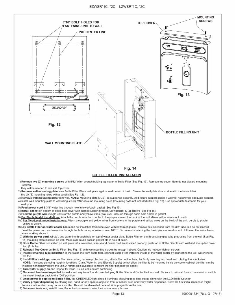
7/16” BOLT HOLES FOR FASTENING UNIT TO WALL
UNIT CENTER LINE
TOP COVER
MOUNTING SCREWS
Fig. 12
BOTTLE FILLER INSTALLATION
1) Remove two (2) mounting screws with 5/32” Allen wrench holding top cover to Bottle Filler (See Fig. 13). Remove top cover. Note do not discard mounting screws,
they will be needed to reinstall top cover. 2) Remove wall mounting plate from Bottle Filler. Place wall plate against wall on top of basin. Center the wall plate side to side with the basin. Mark the six (6) mounting holes with a pencil (See Fig. 12). 3) Remove wall mounting plate from wall. NOTE: Mounting plate MUST be supported securely. Add fixture support carrier if wall will not provide adequate support. 4) Install wall mounting plate to wall using six (6) 7/16” obround mounting holes (mounting bolts not included) (See Fig. 12). Use appropriate fasteners for your wall type. 5) Feed power cord & 3/8” water line through hole in tower/basin gasket (See Fig 15).6) Install gasket on bottom of bottle filler tower with gasket support bracket, (2) washers, & (2) screws (See Fig 16). 7) Feed the purple wire (single units) or the purple and yellow wires (two-level units) up through basin hole & hole in gasket.8) For Single Model installations: Attach the purple wire from cooler to the purple wire on the back of the unit, (Note yellow wire is not used). 8a) For Two-Level model installations: Attach the purple and yellow wires from coolers to the purple and yellow wires on the back of the unit, purple to purple, yellow to yellow. 9) Lay Bottle Filler on water cooler basin and cut insulation from tube even with bottom of gasket, remove this insulation from the 3/8” tube, but do not discard.
Feed the power cord and waterline through the hole on top of water cooler. NOTE: To prevent scratching the basin place a towel or soft cloth over the entire basin when working above it.
10) With the power cord, wire(s), and waterline through hole on top of water cooler place Bottle Filler on the three (3) angled tabs protruding from the wall (See Fig. 14) mounting plate installed on wall. Make sure round boss in gasket fits in hole of basin.
11) Once Bottle Filler is installed on wall plate tabs, waterline, wire(s) and power cord are installed properly, push top of Bottle Filler toward wall and line up top cover two (2) holes. 12) Reinstall Top Cover on Bottle Filler (See Fig. 13) with two mounting screws from step 1 above. Caution, do not over tighten screws. 13) Install remaining tube insulation to the water line from bottle filler, connect Bottle Filler waterline inside of the water cooler by connecting the 3/8” water line to the tee. 14) Install filter cartridge, remove filter from carton, remove protective cap, attach filter to filter head by firmly inserting into head and rotating filter clockwise. NOTE: If existing plumbing rough-in locations (Drain, Water In, and Electric Supply) do not allow the filter to be mounted inside the cooler cabinet the filter can be
installed horizontally below the unit. A retrofit kit is available to mount the filter beneath the cooler. 15) Turn water supply on and inspect for leaks. Fix all leaks before continuing. 16) Once unit has been inspected for leaks and any leaks found corrected, plug Bottle Filler and Cooler Unit into wall. Be sure to reinstall fuse to the circuit or switch the circuit breaker back to the “ON” position. 17) Once power is applied to Bottle Filler, the GREEN LED light should illuminate showing good filter status along with the LCD Bottle Counter. 18) Verify proper dispensing by placing cup, hand, or any opaque object in front of sensor area and verify water dispenses. Note: the first initial dispenses might
have air in line which may cause a sputter. This will be eliminated once all air is purged from the line. 19) Once unit tests out, install Lower Panel back on water cooler. Unit is now ready for use.
Fig. 13
Fig. 14
WALL MOUNTING PLATE
BOTTLE FILLING UNIT

Page 14
EZWSR*1C, *2C LZWSR*1C, *2C
1000001734 (Rev. G - 07/16)
BOTTLE FILLER GASKET
Fig. 15
Fig. 16

Page 15 1000001734 (Rev. G - 07/16)
EZWSR*1C, *2C LZWSR*1C, *2C
WIRING MODIFICATION FOR NON-REFRIGERATED UNIT IN A TWO-LEVEL COOLERIF BOTTLE FILLER COUNTER CONTINUOUSLY ADVANCES
1) DISCONNECT POWER TO ALL UNITS BEFORE PROCEEDING!2) Disconnect ribbed wire (powercord) from the switch wire (from pushbar), add the female to female adapter to wire.3) Remove the smooth larger black wire (powercord) from the solenoid valve. Connect ribbed wire with female adapter from step 2 to where the smooth black wire was connected.4) Add the male to male adapter to the smooth wire removed in step 3.5) Connect the smooth black wire with male adapter to the switch wire (from pushbar) removed in step 2.6) Reconnect power to all units. Verify bottle filler counter advances only when water is flowing.7) Once unit tests out, install lower panels back on water cooler. Units are ready for use.
REVERSE THESE TWO WIRES ON THE NON-REFRIGERATED UNIT OF TWO LEVEL MODELS ONLY USING THE PROVIDED ADAPTERS.
UNIT WITH WIRE ADAPTERS ADDED AND WIRED CORRECTLY
MALE TO MALE ADAPTER FEMALE TO FEMALE ADAPTER
POWERCORD BLACK RIBBED WIRE POWERCORD BLACK SMOOTH WIRE

Page 16
EZWSR*1C, *2C LZWSR*1C, *2C
1000001734 (Rev. G - 07/16)
PLUMBING DIAGRAMSVERSATILE BI-LEVEL
Barb cappedwhen not used
Barb cappedwhen not used
Barb cappedwhen not used
Barb cappedwhen not used
Bottle FillerDrain
Bottle FillerDrain
Bottle FillerDrain
Bottle FillerDrain

Page 17 1000001734 (Rev. G - 07/16)
EZWSR*1C, *2C LZWSR*1C, *2C
VERIFY CONTROL BOARD SOFTWARE1) To verify the software program of the control board the unit will need to be shut down and restarted. The chiller (if present) does not need to be shut down and restarted.2) The units lower panel must be open to access the power cord and wall outlet.3) Shut down the unit by unplugging the power cord from the wall outlet. 4) Restart the unit by plugging the power cord back into the wall outlet.5) Upon start up, the bottle count display will show the software designation of BF11.6) Reference the BF11 instructions for setting the control board.
ACCESSING THE PROGRAMMING BUTTON1) To access the program button remove the top cover of the bottle- filler. Remove the two (2) screws holding top cover to bottle- filler with a 5/32” allen wrench. Remove top cover. Do not discard mounting screws, they will be needed to reinstall the top cove after programming operations are completed. The programming button is located at the top right side of the unit on the control board.
RESET THE FILTER MONITOR1) Instructions apply to filtered units only.2) Depress the program button for approximately 2 seconds until the display changes then release. The display will change and scroll through two messages: “RST FLTR” – Reset Filter Monitor “SETTINGS” – System Settings Sub Menu If the program button is not pushed again the display will scroll through the two messages above for three cycles and then default back to bottle count and be back in run mode.3) When the display changes to “RST FLTR”, depress the button again. The display will change to show “FLTR =”. Depress the button again and the display will show “FLTR =0”4) The Green LED should be illuminated indicating that the visual filter monitor has been reset.
SETTING RANGE OF THE IR SENSOR1) Depress the program button for approximately 2 seconds until the display changes then release. The display will change and scroll through two messages: “RST FLTR” – Reset Filter Status LED “SETTINGS” – System Settings Sub Menu If the program button is not pushed again the display will scroll through the two messages above for three cycles and then default back to bottle count and be back in run mode.2) When the display changes to “SETTINGS”, depress the button again. The display will change to show “RNG SET” - Range set for IR sensor. “UNIT TYP” - Type of unit (REFRIG or NON-RFRG) “FLT SIZE” - Select filter capacity “RST BCNT” - Reset bottle count3) When display shows “RNG SET” push program button once the display will show current value (can be 1 – 10) e.g. “RNG = 3”.4) Once display shows current value push the program button to scroll through value of 1 – 10. Select the desired range setting, "1" being closest to sensor and "10" being farthest away.5) Once range is selected allow approximately 4 seconds to pass and then the display will go back to bottle counter and be in run mode.6) Test bottle filler by placing bottle or hand in front of sensor to make sure water is dispensed.
SETTING UNIT TYPE1) Depress the program button for approximately 2 seconds until the display changes then release. The display will change and scroll through two messages: “RST FLTR” – Reset Filter Status LED “SETTINGS” – System Settings Sub Menu If the program button is not pushed again the display will scroll through the two messages above for three cycles and then default back to bottle count and be back in run mode.
Continued from below:2) When the display changes to “SETTINGS”, depress the button again. The display will change to show “RNG SET” - Range set for IR sensor. “UNIT TYP” - Type of unit (REFRIG or NON-RFRG) “FLT SIZE” - Select filter capacity “RST BCNT” - Reset bottle count3) When display shows “UNIT TYPE” push program button once the display will show current value. Can be REFRIG or NON-RFRG4) Push button once to change value. Once value is selected the display will show the new value. (Can be REFRIG or NON-RFRG) “REFRIG“ - stands for refrigerated product. In this setting the flow rate is estimated at 1.0 gallon per minute. “NON-RFRG“ - stands for nonrefrigerated product. In this setting the flow rate is estimated at 1.5 gallons per minute. Both “REFRIG“ and “NON-RFRG“ simulate 1 bottle equal to 20 oz.5) Allow approximately 4 seconds to pass and the display will return to bottle counter and be in run mode.
RESETTING BOTTLE COUNT1) Depress the program button for approximately 2 seconds until the display changes then release. The display will change and scroll through two messages: “RST FLTR” – Reset Filter Status LED “SETTINGS” – System Settings Sub Menu If the program button is not pushed again the display will scroll through the two messages above for three cycles and then default back to bottle count and be back in run mode.2) When the display changes to “SETTINGS”, depress the button again. The display will change to show: “RNG SET”- Range set for IR sensor. “UNIT TYP” - Type of unit (REFRIG or NON-RFRG) “FLT SIZE” - Select filter capacity “RST BCNT” - Reset bottle count If the button is not pushed again the display will scroll through the four messages above for three cycles and return to run mode.3) When display shows “RST BCNT” push program button once the display will show current value, e.g. “0033183”.4) Once display shows current value push the program button once more to reset back to 0. The display will show BTLCT = 0 for approximately 2 seconds and then return to run mode showing 00000000 bottles. NOTE: Once the bottle count is reset to zero there is no way to return to the previous bottle count.5) Testing the bottle counter: REFRIG units: Place bottle or hand in front of sensor for approximately 9 seconds to see bottle counter count 00000001, (This is based on filling a 20 oz. bottle). NON-RFRG units: Place bottle or hand in front of sensor for approximately 6 seconds to see bottle counter count 00000001, (This is based on filling a 20 oz bottle).
SETTING FILTER CAPACITY1) Depress the program button for approximately 2 seconds until the display changes then release. The display will change and scroll through two messages: “RST FLTR” – Reset Filter Status LED “SETTINGS” – System Settings Sub Menu If the program button is not pushed again the display will scroll through the two messages above for three cycles and then default back to bottle count and be back in run mode.2) When the display changes to “SETTINGS”, depress the button again. The display will change to show: “RNG SET“- Range set for IR sensor. “UNIT TYP“ - Type of unit (REFRIG or NON-RFRG) “FLT SIZE” - Select filter capacity “RST BCNT“ - Reset bottle count If the button is not pushed again the display will scroll through the four messages above for three cycles and return to run mode.3) When display shows “FLT SIZE” push program button once. The display will show current value. Can be 3000GAL or 6000GAL.4) Push program button again to display the desired “FLT SIZE”. 5) Allow approximately 4 seconds to pass and the display will return to bottle counter and be in run mode.
BF11 - BF12 PROGRAMSETTING THE CONTROL BOARD

Page 18
EZWSR*1C, *2C LZWSR*1C, *2C
1000001734 (Rev. G - 07/16)
Bottom View of CoolerFig. 18
Alternate Filter Mounting Location Fig. 19
A
B
3/16” Dia. 2 Holes
EXISTINGHOLE
1-3/8” Dia. Hole
SCREWS
PLASTIC BUSHING
SCREWS
FILTER MOUNTING BRACKETFILTER ASSEMBLY
ALTERNATE FILTER MOUNTING LOCATION
1) Using the supplied punch from the Bottle Filler installation, punch a 1-3/8” dia. hole “A” at the existing hole shown in Fig. 18.2) Drill two 3/16” dia. hole at location “B” shown in Fig 18.3) Remove Filter bracket from filter assembly and reinstall as shown in Fig. 19. Be sure the 3/8” water inlet is facing out.4) Install plastic bushing (supplied) as shown into 1-3/8” hole, bushing must be used so waterlines will not be cut by sharp edges of base plate.5) Install filter assembly to bottom of cooler as shown in Fig. 19 with 2-#8 sheet metal screws.6) Run the inlet and outlet water lines to filter.7) P/N 98551C - LZ Filter Mounting Cover (Light Gray Granite) or P/N 98568C - LZ Filter Mounting Cover (Stainless Steel) may be order to enclose the filter beneath the cooler (Not Shown).
3/8” WATER INLET

Page 19 1000001734 (Rev. G - 07/16)
EZWSR*1C, *2C LZWSR*1C, *2C
REPAIR SERVICE INFORMATION TOLL FREE NUMBER 1.800.260.6640 FOR PARTS, CONTACT YOUR LOCAL DISTRIBUTOR OR CALL 1.800.834.4816
PRINTED IN U.S.A.
ELKAY MANUFACTURING COMPANY • 2222 CAMDEN COURT • OAK BROOK, IL 60523 • 630.574.8484
Fig. 20
DESCRIPTION98543C98544C98545C98632C98546C98547C
100000181398549C98551C98568C98552C
000000133710000018121000001877
Kit - Electrical Package115VKit - IR Sensor 115VKit - Solenoid Valve Replacement 115VKit - Solenoid Valve Replacement 220VKit - Aerator ReplacementKit - Top Cover ReplacementKit - Drain Tower/Basin GasketKit - Hardware & Waterway PartsKit - LZ Filter Mounting Cover (L)Kit - LZ Filter Mounting Cover (S)Kit - Retro Filter MountingKit - Basin ReplacementKit - Bottle Filler DrainKit - Drain Replacement
REPLACEMENT PART KITS
PART NO.
1
2
3
2
WATER FILTER EXPLODED VIEW
DESCRIPTION
12
3
ITEM NO.
PART NO.
51300C98926C
0000000746
Filter Assy-3000 Gal.Kit-Filter Head Fittings-includes John Guest FittingsAssy-Filter & Brkt includes Filter Head/Mtg Brkt/ John Guest Fittings/Screws
WATERSENTRY® PLUS FILTER PARTS LIST(See Fig. 20)
3/8” WaterInlet