
EZ-Mill 4 Axis Tutorial · EZ-MILL 4TH AXIS TUTORIAL - INDEXING BASIC PROGRAMMING STEPS Before we...
58
EZ-Mill 4 th Axis Tutorial
Transcript of EZ-Mill 4 Axis Tutorial · EZ-MILL 4TH AXIS TUTORIAL - INDEXING BASIC PROGRAMMING STEPS Before we...

EZ-Mill 4th Axis Tutorial
Copyright Notice This manual describes software that contains published and unpublished works of authorship proprietary to EZCAM Solutions, Inc. It is made available for use and maintenance of our products. Under copyright laws, this manual, or the software it describes may not be copied in whole, or in part, without prior written consent of EZCAM Solutions, Inc., except in normal software use. The information in this document is subject to change without notice and should not be construed as a com-mitment by EZCAM Solutions, Inc. All software package identifying names appearing herein prefaced with EZ are trademarks of EZCAM Solutions, Inc. , All Rights Reserved. EZ-CAM® and any other references to EZCAM applications software are protected by Copyright 1999-2005 of EZCAM Solutions, Inc. All Rights Reserved. Printed Documentation Copyright 1999-2005 of EZCAM Solutions, Inc. All Rights Reserved.
1. TABLE OF CONTENTS 1
1. TABLE OF CONTENTS
CHAPTER 1. EZ-MILL 4TH AXIS TUTORIAL - INDEXING 1-1 Overview .......................................................................................................... 1-1 4th Axis Indexing .............................................................................................. 1-1 Basic Programming Steps................................................................................. 1-2 The Part ............................................................................................................ 1-3 Setting the Preferences ..................................................................................... 1-4 Loading the Solid Part ...................................................................................... 1-6 Defining The Pocket Curve .............................................................................. 1-8 Defining The Curve Of The Holes ................................................................. 1-10 Defining The Curve Of The Slots................................................................... 1-11 Creating UCS For Side Slot 1......................................................................... 1-13 Creating UCS For Side Slot 2......................................................................... 1-15 Creating The Part Program............................................................................. 1-17 Creating Work Step “Pockets” – Pocketing ................................................... 1-18 Creating Work Step “Holes” – Drilling.......................................................... 1-24 Creating Work Step “Slot1” – Contouring ..................................................... 1-28 Creating Work Step “Slot2” – Contouring ..................................................... 1-32 3D Solid Model Preview ................................................................................ 1-35
EZ-CAM CONTENTS-1
CHAPTER 2. EZ-MILL 4TH AXIS TUTORIAL - WRAPPING 2-1 Overview .......................................................................................................... 2-1 4th Axis Wrapping............................................................................................. 2-1 Basic Programming Steps................................................................................. 2-2 The Part ............................................................................................................ 2-3 Setting the Preferences ..................................................................................... 2-4 Loading the Solid Part ...................................................................................... 2-6 Defining The Groove Curve ............................................................................. 2-8 Creating Work Step “GrooveWrap” – Contouring......................................... 2-10 3D Solid Model Preview ................................................................................ 2-17

CHAPTER 1. EZ-MILL 4TH AXIS TUTORIAL - INDEXING
OVERVIEW This tutorial is intended to teach you how to program the rotary table of your CNC milling machine with the help of EZ-MILL 3D or EZ-MILL Pro’s fourth axis functions. Its aim is to give the basics on using “fourth axis indexing” and “fourth axis wrapping” features. Before starting this tutorial we recommend that you complete other EZ-MILL tutorials and have the required knowledge about creating geometry, curves and milling cycles. First part of the tutorial includes all the steps required to machine a 3D solid part with multi-sides to be indexed by rotary table: import external solid data, prepare curves & user coordinate systems and setup machining data. This will help you to understand the main principles of managing fourth axis operations. Throughout the tutorial you will find important notes , tips or references to the online help where additional information on the commands and functions is provided.
4TH AXIS INDEXING Sample part has four sides to be machined and each side is 90 degrees to each other. This can be achieved by 4th axis rotation of the part that is centrally mounted on the rotary table. The sample part in this tutorial will be rotated around X-axis assuming that it will be machined with a rotary table working around X-axis of the machine. Before machining each side, part will rotate to the appropriate angle by “indexing” process and align the surface parallel to X-Y plane. After rotation stops the regular milling operation cuts defined path on that surface. Then, indexing is repeated for each side of the part to rotate and fix it at desired machining position. Indexing process can be defined in two ways in EZ-Mill, either by entering indexing angles in Work Step Data or by creating auxiliary coordinate systems (UCS) on the machining plane. Both methods will be applied and explained in this tutorial.
EZ-CAM 1-1

EZ-MILL 4TH AXIS TUTORIAL - INDEXING
BASIC PROGRAMMING STEPS Before we continue with the tutorial let us explain the basic steps needed to create the part program. STEP 1. Load (Import) the 3D Solid Model of the Part to be machined
As our sample part we will use a 3D model created in Rhino and saved in its native format “3dm”. Other common CAD translation formats can also be used to import external data to EZ-Mill, such as igs, sat, step, etc.
STEP 2. Define Path Curves from 3D Solid Model
Several curve creation techniques will be applied to get the machining paths from 3D solid model.
STEP 3. Create User Coordinate Systems for Sides
In order to explain how to use UCS for 4th axis indexing, side slots will be machined by defining auxiliary user coordinate systems.
STEP 4. Create Work Steps and set Machining Parameters
Define machining Work Steps and set required fields such as path curves, tool number, feeds and 4th axis parameters and then verify toolpath for active Work Step.
STEP 5. 3D Solid Model Preview
After verification of all work steps we will check machining with 3D Solid Model Preview function on a custom stock which is loaded as a solid part from a 3gx file.
The EZ-MILL 4th Axis Tutorial is setup in Metric with all Inputs
and Dimensions in Millimeters !
1-2 EZ-CAM

EZ-MILL 4TH AXIS TUTORIAL - INDEXING
THE PART The sample for this tutorial is shown below. It is a 140mm x 100mm piece that is 28mm tall. It has two pockets symmetrically located on the top and bottom with a depth of 5mm. Three holes around the big center hole have a diameter of 8mm and they are 10mm deep with identical copies at the bottom. There are two 80x10mm slots with 5mm depth in the front and backside of the part.
Picture 1-1
EZ-CAM 1-3
EZ-MILL 4TH AXIS TUTORIAL - INDEXING
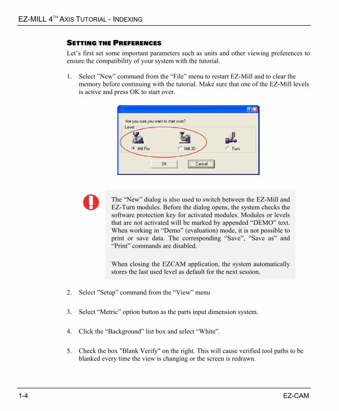
SETTING THE PREFERENCES Let’s first set some important parameters such as units and other viewing preferences to ensure the compatibility of your system with the tutorial. 1. Select ”New” command from the “File” menu to restart EZ-Mill and to clear the
memory before continuing with the tutorial. Make sure that one of the EZ-Mill levels is active and press OK to start over.
The “New” dialog is also used to switch between the EZ-Mill and EZ-Turn modules. Before the dialog opens, the system checks the software protection key for activated modules. Modules or levels that are not activated will be marked by appended “DEMO” text. When working in “Demo” (evaluation) mode, it is not possible to print or save data. The corresponding “Save”, “Save as” and “Print” commands are disabled. When closing the EZCAM application, the system automatically stores the last used level as default for the next session.
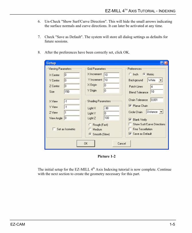
2. Select ”Setup” command from the “View” menu 3. Select “Metric” option button as the parts input dimension system. 4. Click the “Background” list box and select “White”. 5. Check the box "Blank Verify" on the right. This will cause verified tool paths to be
blanked every time the view is changing or the screen is redrawn.
1-4 EZ-CAM
EZ-MILL 4TH AXIS TUTORIAL - INDEXING
6. Un-Check "Show Surf/Curve Direction". This will hide the small arrows indicating the surface normals and curve directions. It can later be activated at any time.
7. Check "Save as Default". The system will store all dialog settings as defaults for
future sessions. 8. After the preferences have been correctly set, click OK.
Picture 1-2 The initial setup for the EZ-MILL 4th Axis Indexing tutorial is now complete. Continue with the next section to create the geometry necessary for this part.
EZ-CAM 1-5

EZ-MILL 4TH AXIS TUTORIAL - INDEXING
LOADING THE SOLID PART We will load the 3D solid part in order to define machining paths and auxiliary user coordinate systems that will be used for indexing to the angled sides. There are two methods to accomplish this process. First method is to import a solid/surface model file in one of the common CAD file formats such as iges, sat, step, dwg, vda or 3dm. Secondly you can open the model in our companion CAD product Rhino and then copy/paste to EZ-Mill using the special command “Paste from Rhino”. In this tutorial we choose the first method and load a 3dm (Rhino native format) file containing the 3D model.
You may refer to “EZ-Mill 3D Tutorial” to get information about
“Copy and Pasting the Model from Rhino”
The “3dm” file containing the 3D model has already been copied into the “EZCAMW\MILLPARTS” folder by the EZ-CAM setup. Follow the steps below to load the data.
Picture 1-3 1. Select “Open” command from the “File” menu to open the file dialog. In Picture 1-3
you can see the dialog displayed on a Windows XP professional workstation system.
1-6 EZ-CAM
EZ-MILL 4TH AXIS TUTORIAL - INDEXING
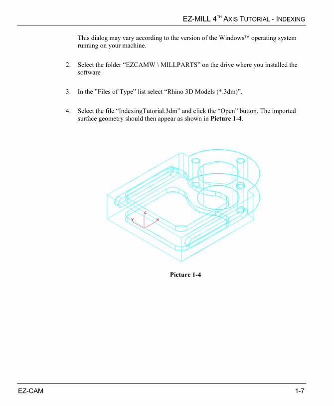
This dialog may vary according to the version of the Windows operating system running on your machine.
2. Select the folder “EZCAMW \ MILLPARTS” on the drive where you installed the
software 3. In the ”Files of Type” list select “Rhino 3D Models (*.3dm)”. 4. Select the file “IndexingTutorial.3dm” and click the “Open” button. The imported
surface geometry should then appear as shown in Picture 1-4.
Picture 1-4
EZ-CAM 1-7
EZ-MILL 4TH AXIS TUTORIAL - INDEXING
DEFINING THE POCKET CURVE We need to create curves to define machining borders or paths using the solid model representation of the 3D part. Since EZ-Mill automatically generates wireframe geometry during the import process we can use those entities or alternatively apply “curve creation from 3D model” commands such as “Face Boundary” or “X-Y Intersection”. Here we use Face Boundary to create the pocket’s boundary curve from its bottom surface. 1. To create the pocket boundary curve choose the “Face Boundary” command from the
“Curves“ menu, type “PocketCrv” as the new ID and click OK.
Face Boundary
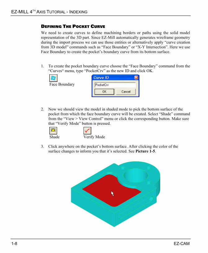
2. Now we should view the model in shaded mode to pick the bottom surface of the
pocket from which the face boundary curve will be created. Select “Shade” command from the “View > View Control” menu or click the corresponding button. Make sure that “Verify Mode” button is pressed.
Shade Verify Mode
3. Click anywhere on the pocket’s bottom surface. After clicking the color of the
surface changes to inform you that it’s selected. See Picture 1-5.
1-8 EZ-CAM
EZ-MILL 4TH AXIS TUTORIAL - INDEXING
Picture 1-5
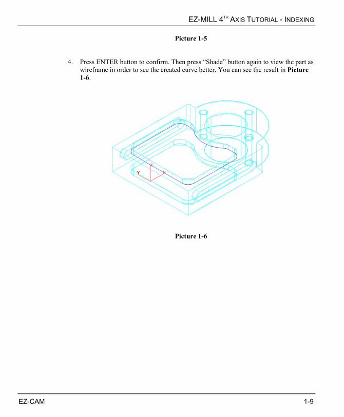
4. Press ENTER button to confirm. Then press “Shade” button again to view the part as wireframe in order to see the created curve better. You can see the result in Picture 1-6.
Picture 1-6
EZ-CAM 1-9
EZ-MILL 4TH AXIS TUTORIAL - INDEXING
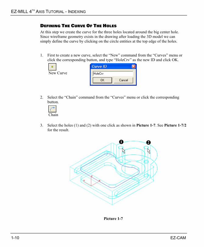
DEFINING THE CURVE OF THE HOLES At this step we create the curve for the three holes located around the big center hole. Since wireframe geometry exists in the drawing after loading the 3D model we can simply define the curve by clicking on the circle entities at the top edge of the holes. 1. First to create a new curve, select the “New” command from the “Curves” menu or
click the corresponding button, and type “HoleCrv” as the new ID and click OK.
New Curve
2. Select the “Chain” command from the “Curves” menu or click the corresponding
button.
Chain
3. Select the holes (1) and (2) with one click as shown in Picture 1-7. See Picture 1-7/2
for the result.
Picture 1-7
1-10 EZ-CAM

EZ-MILL 4TH AXIS TUTORIAL - INDEXING
Picture 1-7/2
DEFINING THE CURVE OF THE SLOTS Now we create the curve for the slots. Since the tool diameter used in this tutorial to cut the slots will be equal to width of the slot our new curve will be a single line connecting the center points. The slot at the opposite side of the part can be machined using the same curve at the front, so we will create only one curve for both slots. 1. First to create a new curve, select the “New” command from the “Curves” menu or
click the corresponding button, and type “SlotCrv” as the new ID and click OK.
New Curve
2. Next, select the “Linear” command from the “Curves” menu or click the
corresponding button. Click “Shade” button to activate shaded viewing and select “Center Circle/Arc” command from the “Edit > Point Picking” menu or click its button. See Picture 3-7.
EZ-CAM 1-11

EZ-MILL 4TH AXIS TUTORIAL - INDEXING
Curve Linear Move
Shade Pick CenterCircle/Arc
3. Click on the half circles (1) and (2) of the slot as shown in Picture 1-8. That will
place the linear curve start and end points at the centers of the half circles. The result is shown in Picture 1-8/2.
Picture 1-8
Picture 1-8/2
1-12 EZ-CAM
EZ-MILL 4TH AXIS TUTORIAL - INDEXING
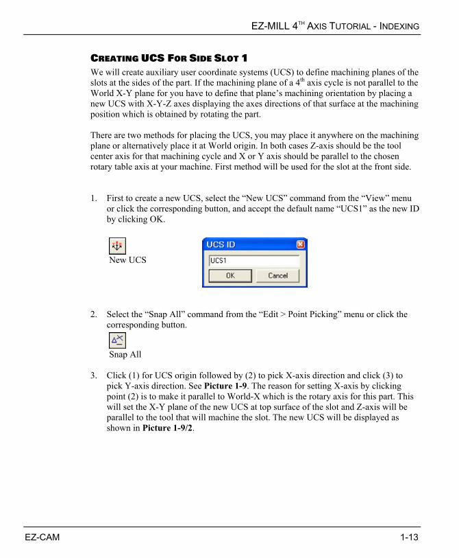
CREATING UCS FOR SIDE SLOT 1 We will create auxiliary user coordinate systems (UCS) to define machining planes of the slots at the sides of the part. If the machining plane of a 4th axis cycle is not parallel to the World X-Y plane for you have to define that plane’s machining orientation by placing a new UCS with X-Y-Z axes displaying the axes directions of that surface at the machining position which is obtained by rotating the part. There are two methods for placing the UCS, you may place it anywhere on the machining plane or alternatively place it at World origin. In both cases Z-axis should be the tool center axis for that machining cycle and X or Y axis should be parallel to the chosen rotary table axis at your machine. First method will be used for the slot at the front side. 1. First to create a new UCS, select the “New UCS” command from the “View” menu
or click the corresponding button, and accept the default name “UCS1” as the new ID by clicking OK.
New UCS
2. Select the “Snap All” command from the “Edit > Point Picking” menu or click the
corresponding button.
Snap All
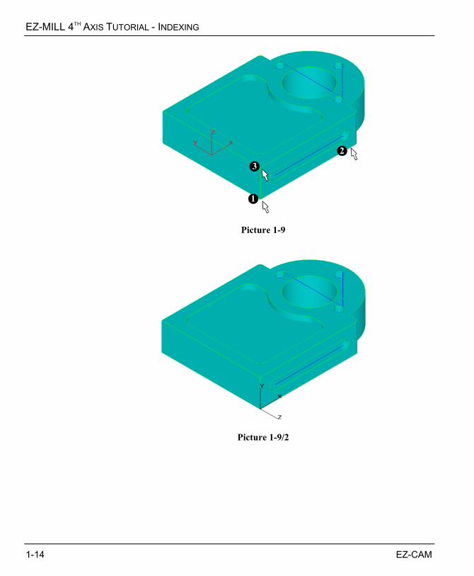
3. Click (1) for UCS origin followed by (2) to pick X-axis direction and click (3) to
pick Y-axis direction. See Picture 1-9. The reason for setting X-axis by clicking point (2) is to make it parallel to World-X which is the rotary axis for this part. This will set the X-Y plane of the new UCS at top surface of the slot and Z-axis will be parallel to the tool that will machine the slot. The new UCS will be displayed as shown in Picture 1-9/2.
EZ-CAM 1-13
EZ-MILL 4TH AXIS TUTORIAL - INDEXING
Picture 1-9
Picture 1-9/2
1-14 EZ-CAM
EZ-MILL 4TH AXIS TUTORIAL - INDEXING
CREATING UCS FOR SIDE SLOT 2 The next step will be to create the UCS that will define the machining axis orientation for the slot at the back side of the part. We will here use the second method described in the previous subject and place the UCS at the World coordinate system origin. Z-axis will be parallel to the slot’s surface normal (that is World Y-axis) and X-axis will be parallel to World X-axis which is the rotation axis of the part. 1. To create a new UCS, select the “New UCS” command from the “View” menu or
click the corresponding button, and accept the default name “UCS2” as the new ID by clicking OK.
New UCS
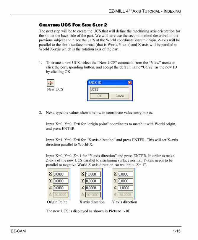
2. Next, type the values shown below in coordinate value entry boxes. Input X=0, Y=0, Z=0 for “origin point” coordinates to match it with World origin,
and press ENTER. Input X=1, Y=0, Z=0 for “X axis direction” and press ENTER. This will set X-axis
direction parallel to World-X. Input X=0, Y=0, Z=-1 for “Y axis direction” and press ENTER. In order to make
Z-axis of the new UCS parallel to machining surface normal, Y-axis needs to be parallel to negative World Z-axis direction, so we input “Z=-1”.
Origin Point X axis direction Y axis direction
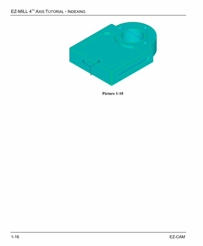
The new UCS is displayed as shown in Picture 1-10.
EZ-CAM 1-15
EZ-MILL 4TH AXIS TUTORIAL - INDEXING
Picture 1-10
1-16 EZ-CAM
EZ-MILL 4TH AXIS TUTORIAL - INDEXING
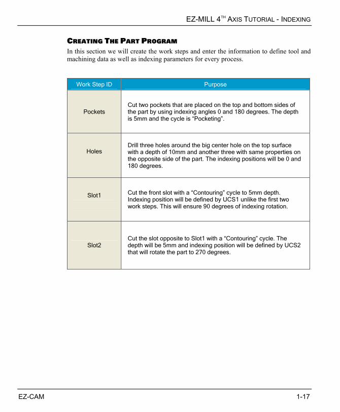
CREATING THE PART PROGRAM In this section we will create the work steps and enter the information to define tool and machining data as well as indexing parameters for every process.
Work Step ID Purpose
Pockets Cut two pockets that are placed on the top and bottom sides of the part by using indexing angles 0 and 180 degrees. The depth is 5mm and the cycle is “Pocketing”.
Holes
Drill three holes around the big center hole on the top surface with a depth of 10mm and another three with same properties on the opposite side of the part. The indexing positions will be 0 and 180 degrees.
Slot1
Cut the front slot with a “Contouring” cycle to 5mm depth. Indexing position will be defined by UCS1 unlike the first two work steps. This will ensure 90 degrees of indexing rotation.
Slot2 Cut the slot opposite to Slot1 with a “Contouring” cycle. The depth will be 5mm and indexing position will be defined by UCS2 that will rotate the part to 270 degrees.
EZ-CAM 1-17
EZ-MILL 4TH AXIS TUTORIAL - INDEXING
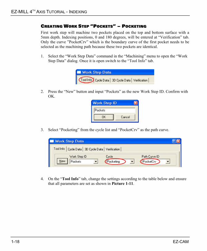
CREATING WORK STEP „POCKETS‰ – POCKETING First work step will machine two pockets placed on the top and bottom surface with a 5mm depth. Indexing positions, 0 and 180 degrees, will be entered at “Verification” tab. Only the curve ”PocketCrv” which is the boundary curve of the first pocket needs to be selected as the machining path because these two pockets are identical. 1. Select the “Work Step Data” command in the “Machining” menu to open the “Work
Step Data” dialog. Once it is open switch to the “Tool Info” tab.
2. Press the “New” button and input “Pockets” as the new Work Step ID. Confirm with
OK.
3. Select “Pocketing” from the cycle list and “PocketCrv” as the path curve.
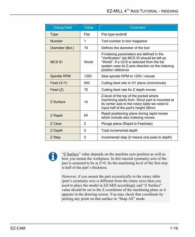
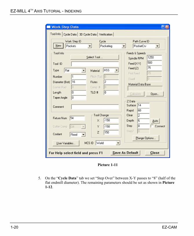
4. On the “Tool Info” tab, change the settings according to the table below and ensure
that all parameters are set as shown in Picture 1-11.
1-18 EZ-CAM
EZ-MILL 4TH AXIS TUTORIAL - INDEXING
Dialog Field Value Comment
Type Flat Flat type endmill
Number 1 Tool number in tool magazine
Diameter (Bot.) 16 Defines the diameter of the tool
MCS ID World
If indexing parameters are defined in the “Verification” tab MCS ID should be left as “World”. If a UCS is selected from the list system uses its Z-axis direction as the indexing position reference
Spindle RPM 1250 Sets spindle RPM to 1250 / minute
Feed (X-Y) 500 Cutting feed rate in XY plane (mm/minute)
Feed (Z) 75 Cutting feed rate for Z depth moves
Z Surface 14
Z-level of the top of the pocket where machining starts from. Since part is mounted at its center axis to the rotary table we need to input half of the part’s height 28mm
Z Rapid 60 Rapid positioning plane during rapid moves which include also indexing moves
Z Clear 2 Plunge plane (Rapid to Feedrate)
Z Depth 5 Total incremental depth
Z Step 0 Incremental step (0 means one pass to depth)
“Z Surface” value depends on the machine zero position as well as how you mount the workpiece. In this tutorial symmetry axis of the part is assumed to be at Z=0. So the machining level of the first step is half of the part’s thickness. However, if you mount the part eccentrically to the rotary table (part’s symmetry axis is different from the rotary axis) then you need to place the model in EZ-Mill accordingly and “Z Surface” value should be set to the Z coordinate of the machining plane as it appears in the drawing screen. You may check that coordinate by picking any point on that surface in “Snap All” mode.
EZ-CAM 1-19
EZ-MILL 4TH AXIS TUTORIAL - INDEXING
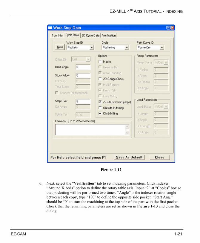
Picture 1-11 5. On the “Cycle Data” tab we set “Step Over” between X-Y passes to “8” (half of the
flat endmill diameter). The remaining parameters should be set as shown in Picture 1-12.
1-20 EZ-CAM
EZ-MILL 4TH AXIS TUTORIAL - INDEXING
Picture 1-12 6. Next, select the “Verification” tab to set indexing parameters. Click Indexer
“Around X Axis” option to define the rotary table axis. Input “2” at “Copies” box so that pocketing will be performed two times. “Angle” is the indexer rotation angle between each copy, type “180” to define the opposite side pocket. “Start Ang.” should be “0” to start the machining at the top side of the part with the first pocket. Check that the remaining parameters are set as shown in Picture 1-13 and close the dialog.
EZ-CAM 1-21

EZ-MILL 4TH AXIS TUTORIAL - INDEXING
Picture 1-13 7. Click the “Verify” button and the system starts calculating the toolpath. See Picture
1-14.
Verify
1-22 EZ-CAM
EZ-MILL 4TH AXIS TUTORIAL - INDEXING
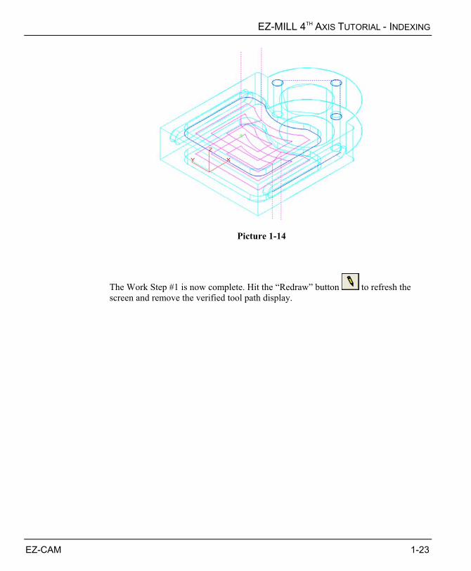
Picture 1-14
The Work Step #1 is now complete. Hit the “Redraw” button to refresh the screen and remove the verified tool path display.
EZ-CAM 1-23
EZ-MILL 4TH AXIS TUTORIAL - INDEXING
CREATING WORK STEP „HOLES‰ – DRILLING Second work step is created to drill three holes on the top and then copy them to the opposite side by entering indexing parameters in Work Step Data “Verification” tab. 1. Select the “Work Step Data” command in the “Machining” menu to open the “Work
Step Data” dialog. Once it is open switch to the “Tool Info” tab, press the “New” button and input “Holes” as the new Work Step ID. Confirm with OK.
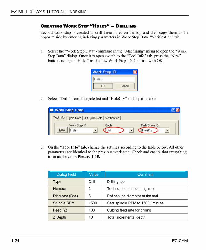
2. Select “Drill” from the cycle list and “HoleCrv” as the path curve.
3. On the “Tool Info” tab, change the settings according to the table below. All other
parameters are identical to the previous work step. Check and ensure that everything is set as shown in Picture 1-15.
Dialog Field Value Comment
Type Drill Drilling tool
Number 2 Tool number in tool magazine.
Diameter (Bot.) 8 Defines the diameter of the tool
Spindle RPM 1500 Sets spindle RPM to 1500 / minute
Feed (Z) 100 Cutting feed rate for drilling
Z Depth 10 Total incremental depth
1-24 EZ-CAM
EZ-MILL 4TH AXIS TUTORIAL - INDEXING
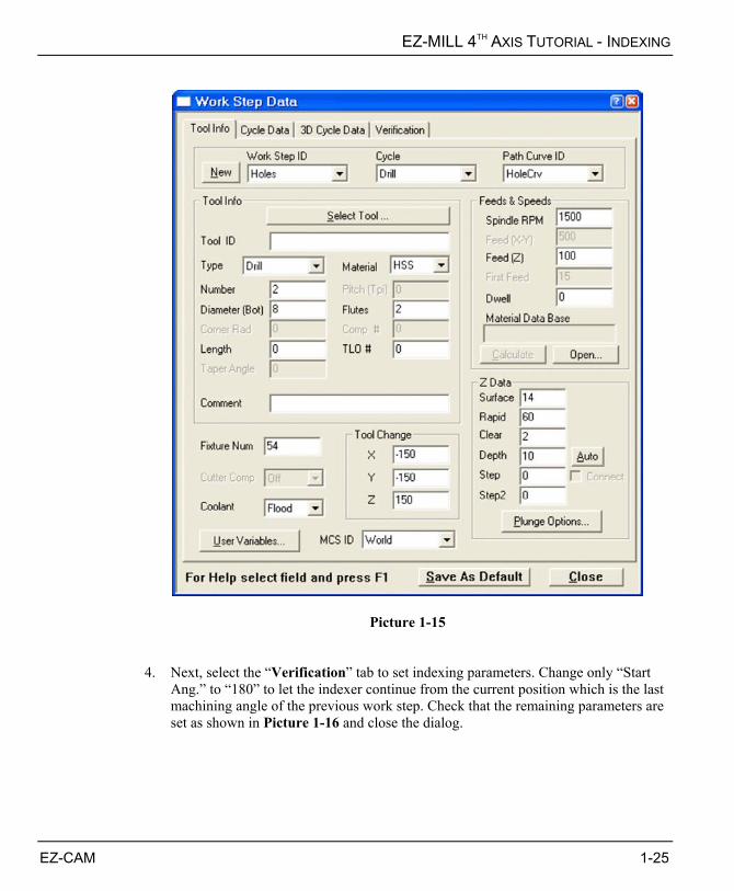
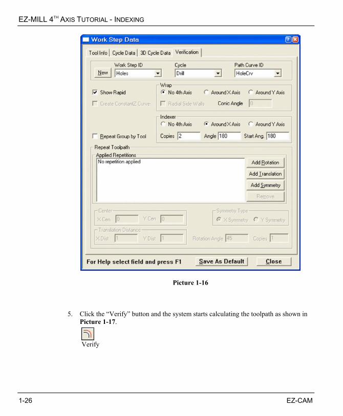
Picture 1-15 4. Next, select the “Verification” tab to set indexing parameters. Change only “Start
Ang.” to “180” to let the indexer continue from the current position which is the last machining angle of the previous work step. Check that the remaining parameters are set as shown in Picture 1-16 and close the dialog.
EZ-CAM 1-25
EZ-MILL 4TH AXIS TUTORIAL - INDEXING
Picture 1-16 5. Click the “Verify” button and the system starts calculating the toolpath as shown in
Picture 1-17.
Verify
1-26 EZ-CAM

EZ-MILL 4TH AXIS TUTORIAL - INDEXING
Picture 1-17
The Work Step #2 is now complete. Hit the “Redraw” button to refresh the screen and remove the verified tool path display.
EZ-CAM 1-27
EZ-MILL 4TH AXIS TUTORIAL - INDEXING
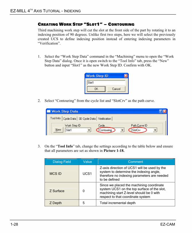
CREATING WORK STEP „SLOT1‰ – CONTOURING Third machining work step will cut the slot at the front side of the part by rotating it to an indexing position of 90 degrees. Unlike first two steps, here we will select the previously created UCS to define indexing position instead of entering indexing parameters in “Verification”. 1. Select the “Work Step Data” command in the “Machining” menu to open the “Work
Step Data” dialog. Once it is open switch to the “Tool Info” tab, press the “New” button and input “Slot1” as the new Work Step ID. Confirm with OK.
2. Select “Contouring” from the cycle list and “SlotCrv” as the path curve.
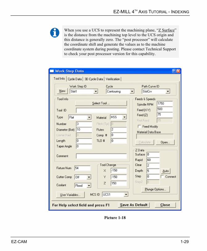
3. On the “Tool Info” tab, change the settings according to the table below and ensure
that all parameters are set as shown in Picture 1-18.
Dialog Field Value Comment
MCS ID UCS1
Z-axis direction of UCS1 will be used by the system to determine the indexing angle, therefore no indexing parameters are needed to be defined
Z Surface 0
Since we placed the machining coordinate system UCS1 on the top surface of the slot, machining start Z-level should be 0 with respect to that coordinate system
Z Depth 5 Total incremental depth
1-28 EZ-CAM
EZ-MILL 4TH AXIS TUTORIAL - INDEXING
When you use a UCS to represent the machining plane, “Z Surface” is the distance from the machining top level to the UCS origin and this distance is generally zero. The “post processor” will calculate the coordinate shift and generate the values as to the machine coordinate system during posting. Please contact Technical Support to check your post processor version for this capability.
Picture 1-18
EZ-CAM 1-29
EZ-MILL 4TH AXIS TUTORIAL - INDEXING
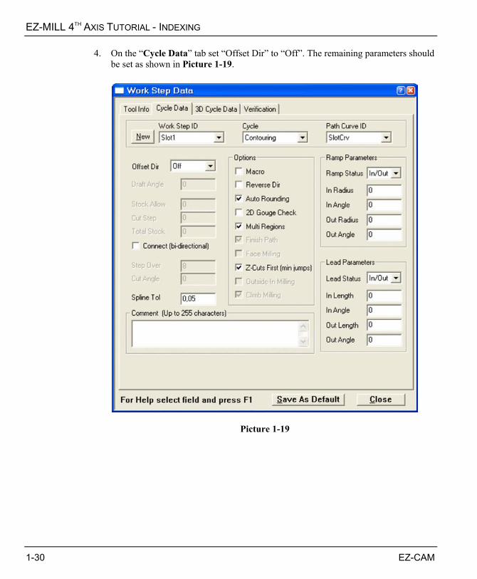
4. On the “Cycle Data” tab set “Offset Dir” to “Off”. The remaining parameters should be set as shown in Picture 1-19.
Picture 1-19
1-30 EZ-CAM
EZ-MILL 4TH AXIS TUTORIAL - INDEXING
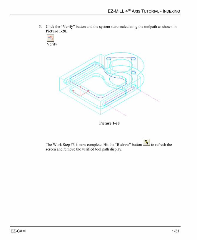
5. Click the “Verify” button and the system starts calculating the toolpath as shown in
Picture 1-20.
Verify
Picture 1-20
The Work Step #3 is now complete. Hit the “Redraw” button to refresh the screen and remove the verified tool path display.
EZ-CAM 1-31
EZ-MILL 4TH AXIS TUTORIAL - INDEXING
CREATING WORK STEP „SLOT2‰ – CONTOURING The last work step of this tutorial will machine the slot at the back side of the part. We will use the same path curve as the previous work step that machined the frontal slot, which is identical with this one. Instead of defining indexing parameters in work step data UCS will be used. 1. Select the “Work Step Data” command in the “Machining” menu to open the “Work
Step Data” dialog. Once it is open switch to the “Tool Info” tab, press the “New” button and input “Slot2” as the new Work Step ID. Confirm with OK.
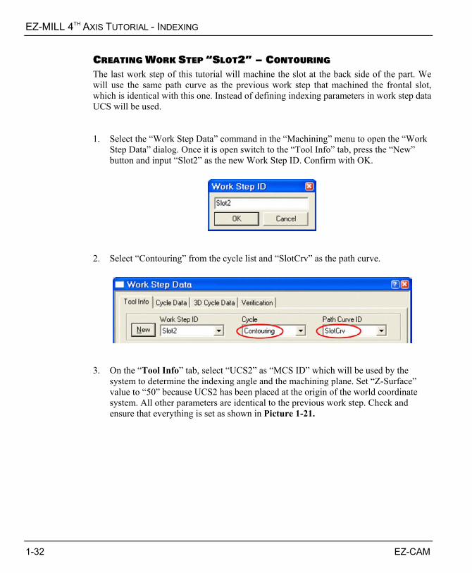
2. Select “Contouring” from the cycle list and “SlotCrv” as the path curve.
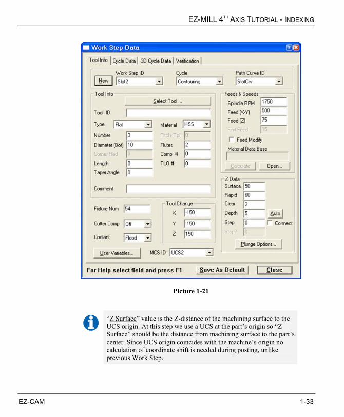
3. On the “Tool Info” tab, select “UCS2” as “MCS ID” which will be used by the
system to determine the indexing angle and the machining plane. Set “Z-Surface” value to “50” because UCS2 has been placed at the origin of the world coordinate system. All other parameters are identical to the previous work step. Check and ensure that everything is set as shown in Picture 1-21.
1-32 EZ-CAM
EZ-MILL 4TH AXIS TUTORIAL - INDEXING
Picture 1-21
“Z Surface” value is the Z-distance of the machining surface to the UCS origin. At this step we use a UCS at the part’s origin so “Z Surface” should be the distance from machining surface to the part’s center. Since UCS origin coincides with the machine’s origin no calculation of coordinate shift is needed during posting, unlike previous Work Step.
EZ-CAM 1-33
EZ-MILL 4TH AXIS TUTORIAL - INDEXING
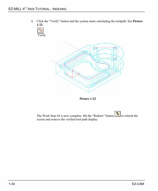
4. Click the “Verify” button and the system starts calculating the toolpath. See Picture
1-22.
Verify
Picture 1-22
The Work Step #4 is now complete. Hit the “Redraw” button to refresh the screen and remove the verified tool path display.
1-34 EZ-CAM

EZ-MILL 4TH AXIS TUTORIAL - INDEXING
3D SOLID MODEL PREVIEW We have completed arranging all the work steps and now we will run 3D solid model preview to see the result of all the machining operations applied to a solid block. Instead of a rectangular block we will use a custom solid block which has the general shape of the part with the big center hole. The best way of using a custom stock for simulation is to load an “stl” file that will represent a single piece 3D model created by a CAD software. It is also possible to use other supported CAD file formats by combining the surfaces in EZ-Mill as custom stock, but this is out of the focus of this tutorial. 1. To load the 3D stock file select “File > Open”, find “IndexingTutorial-stock.stl” file
in “MillParts” folder and click “Open”. 2. After loading the file select “Rename” command from the “Edit” menu. Click to
choose “Surface” option, find and click “Rhinoceros Binary STL…” in the list. Type “StockSrf” in “New Name” box and click “Rename” button. Press OK to confirm. See Picture 1-23.
Picture 1-23 You may use the “Blank” command to hide “StockSrf”, since it’s only used for 3D
simulation and can always stay as hidden.
EZ-CAM 1-35

EZ-MILL 4TH AXIS TUTORIAL - INDEXING
3. Select the “Stock & Optimization Setup” command from the “Machining” menu and select “Custom Stock” from “Stock Setup” as shown in Picture 1-24. Close the dialog with OK.
Picture 1-24
1-36 EZ-CAM
EZ-MILL 4TH AXIS TUTORIAL - INDEXING
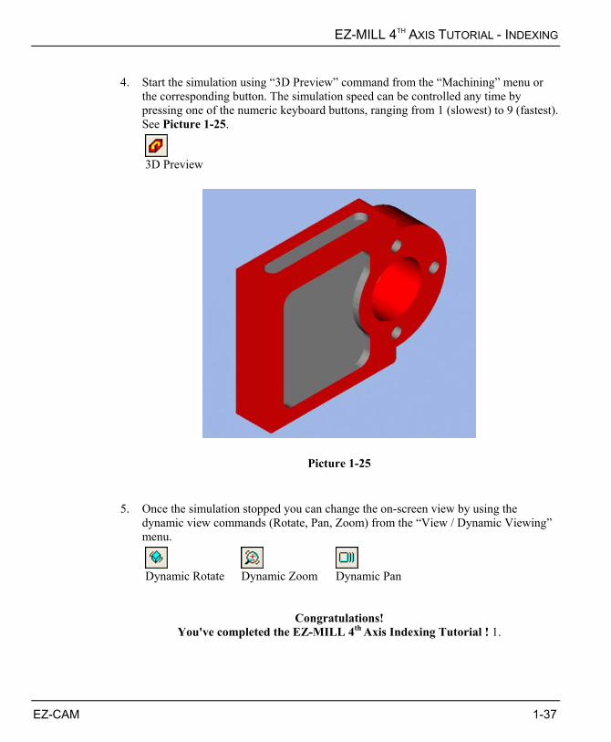
4. Start the simulation using “3D Preview” command from the “Machining” menu or
the corresponding button. The simulation speed can be controlled any time by pressing one of the numeric keyboard buttons, ranging from 1 (slowest) to 9 (fastest). See Picture 1-25.
3D Preview
Picture 1-25 5. Once the simulation stopped you can change the on-screen view by using the
dynamic view commands (Rotate, Pan, Zoom) from the “View / Dynamic Viewing” menu.
Dynamic Rotate Dynamic Zoom Dynamic Pan
Congratulations! You've completed the EZ-MILL 4th Axis Indexing Tutorial ! 1.
EZ-CAM 1-37
CHAPTER 2. EZ-MILL 4TH AXIS TUTORIAL - WRAPPING
OVERVIEW This tutorial is intended to teach you how to program the rotary table of your CNC milling machine with the help of EZ-MILL 3D or EZ-MILL Pro’s fourth axis functions. Its aim is to give the basics on using “fourth axis wrapping” features. Before starting this tutorial we recommend that you complete other EZ-MILL tutorials and have the required knowledge about creating geometry, curves and milling cycles. The tutorial includes the steps that explain loading a solid model file, preparing the machining curve and machining data for a 3D cylindrical part that needs to be machined by 4th axis wrapping – simultaneous cutting operation. This will help you to understand the main principles of managing fourth axis wrapping operations. Throughout the tutorial you will find important notes , tips or references to the online help where additional information on the commands and functions is provided.
4TH AXIS WRAPPING The sample of this tutorial is a cylindrical part that has a cam groove on its circumference. Because the groove is wrapped around the cylinder, the tool will move along the center axis synchronized with 4th axis rotation to achieve the cam profile around the part. There are two choices regarding part’s center axis, X or Y, which corresponds to the orientation of the rotary table on the CNC machine. Therefore, you need to place the model in EZ-Mill accordingly. In this tutorial a rotary table working around X-axis is assumed.
EZ-CAM 2-1
EZ-MILL 4TH AXIS TUTORIAL - WRAPPING
BASIC PROGRAMMING STEPS Before we continue with the tutorial let us explain the basic steps needed to create the part program. STEP 1. Load the 3D Solid Model of the Part to be machined
A 3D cylindrical solid part will be loaded in EZ-Mill at the beginning of the tutorial. This part is aligned at the machining position and saved in EZ-Mill as geo and 3gx file formats, however it is possible to import external data as iges, sat, step, etc.
STEP 2. Define the Path Curve from 3D Solid Model
Face Boundary command will be used to get the side contour curve of the groove to be machined.
STEP 4. Create the Work Step and set Machining Parameters
Define the Work Step and set machining data such as tool number, feeds, etc. Then select path curve and 4th axis options followed by verification of the toolpath.
STEP 5. 3D Solid Model Preview
Finally, run solid machining simulation for a realistic preview of the machining process and the finished part.
The EZ-MILL 4th Axis Tutorial is setup in Inch with all Inputs
and Dimensions in Inch !
2-2 EZ-CAM
EZ-MILL 4TH AXIS TUTORIAL - WRAPPING
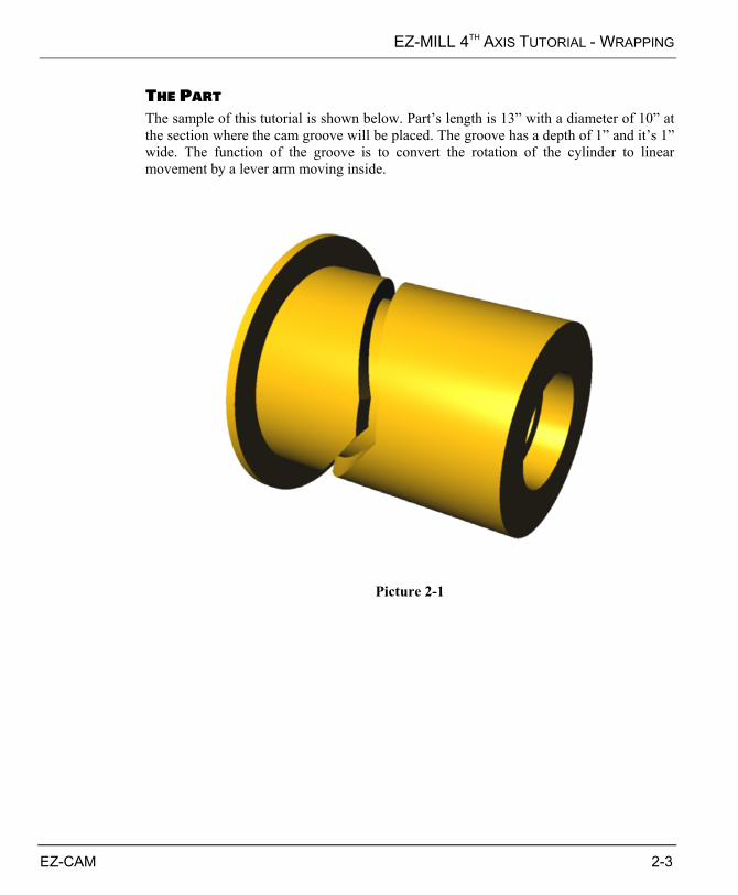
THE PART The sample of this tutorial is shown below. Part’s length is 13” with a diameter of 10” at the section where the cam groove will be placed. The groove has a depth of 1” and it’s 1” wide. The function of the groove is to convert the rotation of the cylinder to linear movement by a lever arm moving inside.
Picture 2-1
EZ-CAM 2-3
EZ-MILL 4TH AXIS TUTORIAL - WRAPPING
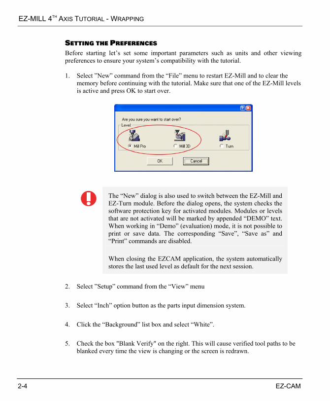
SETTING THE PREFERENCES Before starting let’s set some important parameters such as units and other viewing preferences to ensure your system’s compatibility with the tutorial. 1. Select ”New” command from the “File” menu to restart EZ-Mill and to clear the
memory before continuing with the tutorial. Make sure that one of the EZ-Mill levels is active and press OK to start over.
The “New” dialog is also used to switch between the EZ-Mill and EZ-Turn module. Before the dialog opens, the system checks the software protection key for activated modules. Modules or levels that are not activated will be marked by appended “DEMO” text. When working in “Demo” (evaluation) mode, it is not possible to print or save data. The corresponding “Save”, “Save as” and “Print” commands are disabled. When closing the EZCAM application, the system automatically stores the last used level as default for the next session.
2. Select ”Setup” command from the “View” menu 3. Select “Inch” option button as the parts input dimension system. 4. Click the “Background” list box and select “White”. 5. Check the box "Blank Verify" on the right. This will cause verified tool paths to be
blanked every time the view is changing or the screen is redrawn.
2-4 EZ-CAM
EZ-MILL 4TH AXIS TUTORIAL - WRAPPING
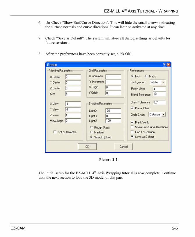
6. Un-Check "Show Surf/Curve Direction". This will hide the small arrows indicating the surface normals and curve directions. It can later be activated at any time.
7. Check "Save as Default". The system will store all dialog settings as defaults for
future sessions. 8. After the preferences have been correctly set, click OK.
Picture 2-2 The initial setup for the EZ-MILL 4th Axis Wrapping tutorial is now complete. Continue with the next section to load the 3D model of this part.
EZ-CAM 2-5

EZ-MILL 4TH AXIS TUTORIAL - WRAPPING
LOADING THE SOLID PART We will load the 3D solid part in order to define the machining path. The part is previously imported and saved in EZ-Mill as “3gx” and “geo” formats. These files are located in the sample parts folder. 3gx file includes the surface data of the 3D model and the geo file keeps the entities such as surface edges & wireframe geometry.
You may refer to “EZ-Mill 3D Tutorial” and “EZ-Mill 4th Axis –
Indexing Tutorial” to get information about other methods for loading a solid part
The “3gx” and “geo” files containing the 3D model have already been copied into the “EZCAMW\MILLPARTS” folder by the EZ-CAM setup. Follow the steps below to load the data.
Picture 2-3 1. Select “Open” command from the “File” menu to open the file dialog. In Picture 2-3
you can see the dialog displayed on a Windows XP professional workstation system. This dialog may vary according to the version of the Windows operating system running on your machine.
2-6 EZ-CAM

EZ-MILL 4TH AXIS TUTORIAL - WRAPPING
2. Select the folder “EZCAMW \ MILLPARTS” on the drive where you installed the
software 3. Select both files “WrappingTutorial1.3gx” and “WrappingTutorial1.geo” at the same
time and click the “Open” button. Alternatively, you may select and open the files one by one. The imported surface geometry should appear as shown in Picture 2-4.
Picture 2-4
EZ-CAM 2-7
EZ-MILL 4TH AXIS TUTORIAL - WRAPPING
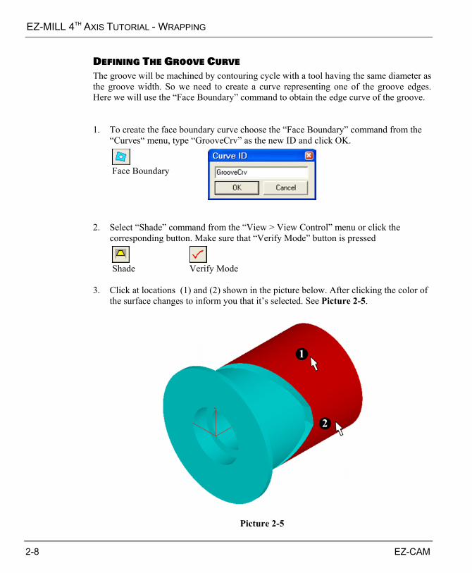
DEFINING THE GROOVE CURVE The groove will be machined by contouring cycle with a tool having the same diameter as the groove width. So we need to create a curve representing one of the groove edges. Here we will use the “Face Boundary” command to obtain the edge curve of the groove. 1. To create the face boundary curve choose the “Face Boundary” command from the
“Curves“ menu, type “GrooveCrv” as the new ID and click OK.
Face Boundary
2. Select “Shade” command from the “View > View Control” menu or click the
corresponding button. Make sure that “Verify Mode” button is pressed
Shade Verify Mode
3. Click at locations (1) and (2) shown in the picture below. After clicking the color of
the surface changes to inform you that it’s selected. See Picture 2-5.
Picture 2-5
2-8 EZ-CAM

EZ-MILL 4TH AXIS TUTORIAL - WRAPPING
4. Press ENTER button to confirm. Then press “Shade” button again to view the part as wireframe in order to see the created curves better. Two curves are formed on both edges of the surfaces; we will use the one that is adjacent to the groove as the machining path. You can see the result in Picture 2-6.
Picture 2-6
EZ-CAM 2-9
EZ-MILL 4TH AXIS TUTORIAL - WRAPPING
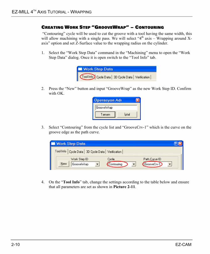
CREATING WORK STEP „GROOVEWRAP‰ – CONTOURING “Contouring” cycle will be used to cut the groove with a tool having the same width, this will allow machining with a single pass. We will select “4th axis – Wrapping around X-axis” option and set Z-Surface value to the wrapping radius on the cylinder. 1. Select the “Work Step Data” command in the “Machining” menu to open the “Work
Step Data” dialog. Once it is open switch to the “Tool Info” tab.
2. Press the “New” button and input “GrooveWrap” as the new Work Step ID. Confirm
with OK.
3. Select “Contouring” from the cycle list and “GrooveCrv-1” which is the curve on the
groove edge as the path curve.
4. On the “Tool Info” tab, change the settings according to the table below and ensure
that all parameters are set as shown in Picture 2-11.
2-10 EZ-CAM
EZ-MILL 4TH AXIS TUTORIAL - WRAPPING
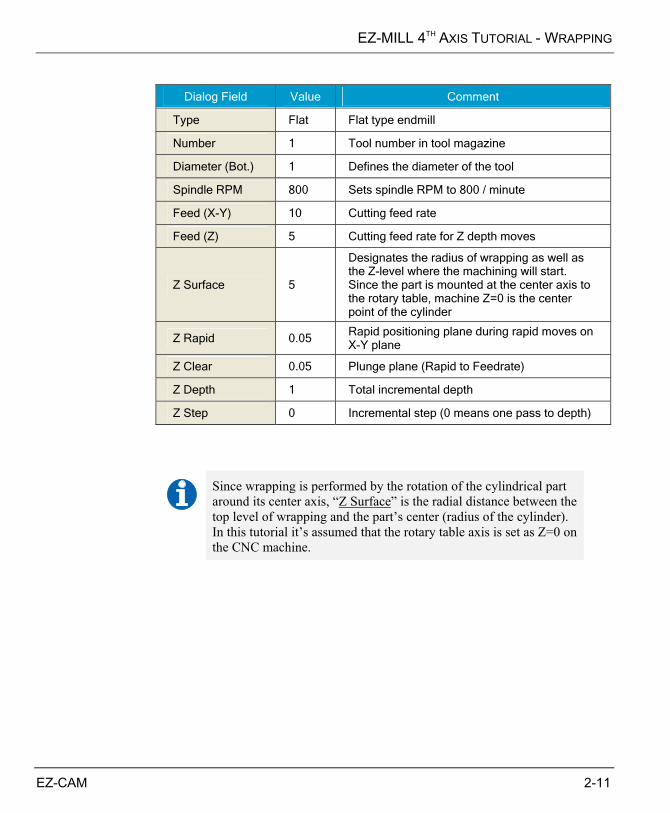
Dialog Field Value Comment
Type Flat Flat type endmill
Number 1 Tool number in tool magazine
Diameter (Bot.) 1 Defines the diameter of the tool
Spindle RPM 800 Sets spindle RPM to 800 / minute
Feed (X-Y) 10 Cutting feed rate
Feed (Z) 5 Cutting feed rate for Z depth moves
Z Surface 5
Designates the radius of wrapping as well as the Z-level where the machining will start. Since the part is mounted at the center axis to the rotary table, machine Z=0 is the center point of the cylinder
Z Rapid 0.05 Rapid positioning plane during rapid moves on X-Y plane
Z Clear 0.05 Plunge plane (Rapid to Feedrate)
Z Depth 1 Total incremental depth
Z Step 0 Incremental step (0 means one pass to depth)
Since wrapping is performed by the rotation of the cylindrical part around its center axis, “Z Surface” is the radial distance between the top level of wrapping and the part’s center (radius of the cylinder). In this tutorial it’s assumed that the rotary table axis is set as Z=0 on the CNC machine.
EZ-CAM 2-11

EZ-MILL 4TH AXIS TUTORIAL - WRAPPING
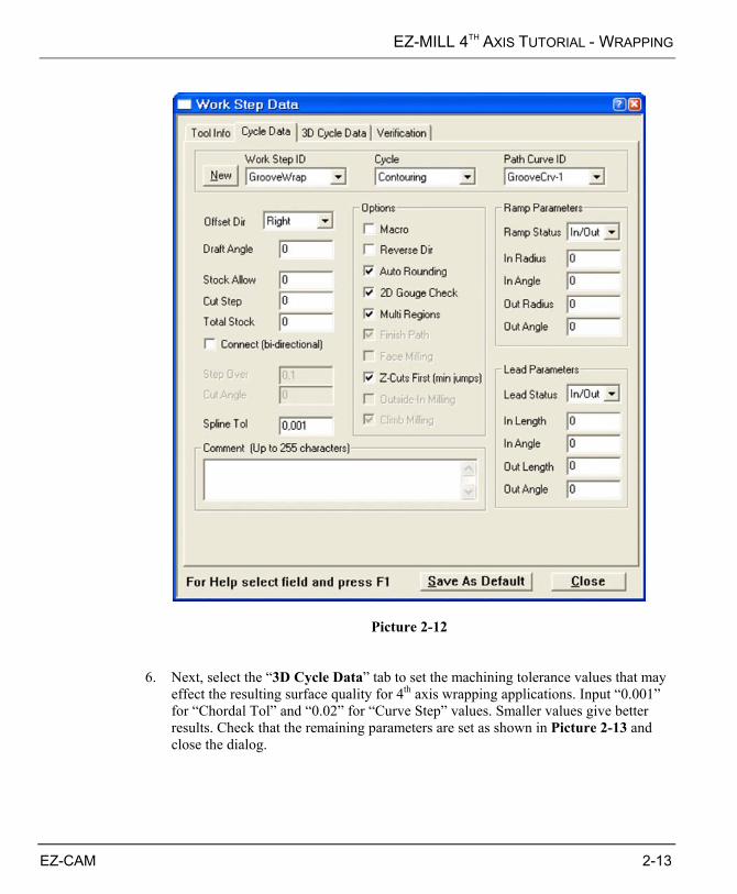
Picture 2-11 5. On the “Cycle Data” tab we set the “Offset Dir.” as “Right” to obtain the toolpath at
the groove side of the machining curve. The remaining parameters should be set as shown in Picture 2-12.
2-12 EZ-CAM
EZ-MILL 4TH AXIS TUTORIAL - WRAPPING
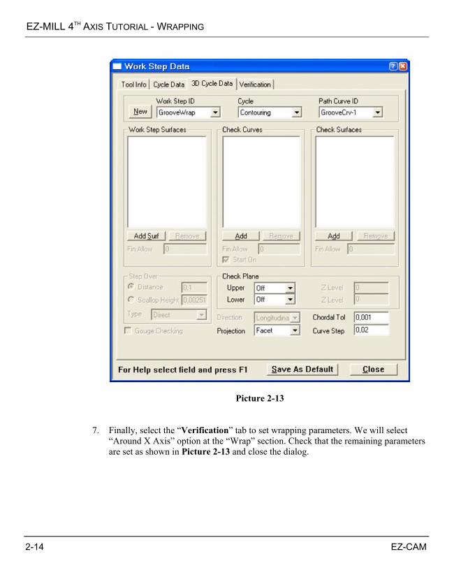
Picture 2-12 6. Next, select the “3D Cycle Data” tab to set the machining tolerance values that may
effect the resulting surface quality for 4th axis wrapping applications. Input “0.001” for “Chordal Tol” and “0.02” for “Curve Step” values. Smaller values give better results. Check that the remaining parameters are set as shown in Picture 2-13 and close the dialog.
EZ-CAM 2-13
EZ-MILL 4TH AXIS TUTORIAL - WRAPPING
Picture 2-13 7. Finally, select the “Verification” tab to set wrapping parameters. We will select
“Around X Axis” option at the “Wrap” section. Check that the remaining parameters are set as shown in Picture 2-13 and close the dialog.
2-14 EZ-CAM

EZ-MILL 4TH AXIS TUTORIAL - WRAPPING
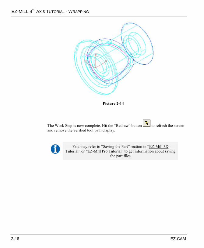
Picture 2-13 7. Click the “Verify” button and the system starts calculating the toolpath. See Picture
2-14.
Verify
EZ-CAM 2-15
EZ-MILL 4TH AXIS TUTORIAL - WRAPPING
Picture 2-14
The Work Step is now complete. Hit the “Redraw” button to refresh the screen and remove the verified tool path display.
You may refer to “Saving the Part” section in “EZ-Mill 3D
Tutorial” or “EZ-Mill Pro Tutorial” to get information about saving the part files
2-16 EZ-CAM
EZ-MILL 4TH AXIS TUTORIAL - WRAPPING
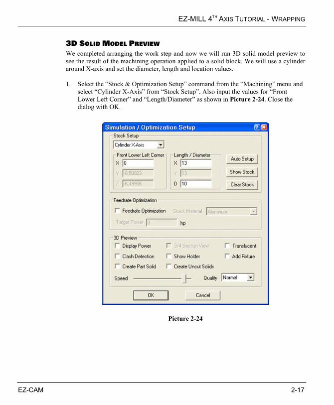
3D SOLID MODEL PREVIEW We completed arranging the work step and now we will run 3D solid model preview to see the result of the machining operation applied to a solid block. We will use a cylinder around X-axis and set the diameter, length and location values. 1. Select the “Stock & Optimization Setup” command from the “Machining” menu and
select “Cylinder X-Axis” from “Stock Setup”. Also input the values for “Front Lower Left Corner” and “Length/Diameter” as shown in Picture 2-24. Close the dialog with OK.
Picture 2-24
EZ-CAM 2-17
EZ-MILL 4TH AXIS TUTORIAL - WRAPPING
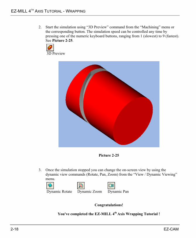
2. Start the simulation using “3D Preview” command from the “Machining” menu or
the corresponding button. The simulation speed can be controlled any time by pressing one of the numeric keyboard buttons, ranging from 1 (slowest) to 9 (fastest). See Picture 2-25.
3D Preview
Picture 2-25 3. Once the simulation stopped you can change the on-screen view by using the
dynamic view commands (Rotate, Pan, Zoom) from the “View / Dynamic Viewing” menu.
Dynamic Rotate Dynamic Zoom Dynamic Pan
Congratulations!
You've completed the EZ-MILL 4th Axis Wrapping Tutorial !
2-18 EZ-CAM


![Mastercam X6 Mill Level 1 Tutorial 1[1]](https://static.fdocuments.us/doc/165x107/577cb45d1a28aba7118c6df5/mastercam-x6-mill-level-1-tutorial-11.jpg)