Extrinsic Evolution of Finite State Machine
12
Extrinsic Evolution of Finite State Machine A. Belgasem 1 , T. Kalganova 2 , A. E. A. Almaini 3 3 , 1 School of Engineering Napier University 10 Colinton Road, Edinburgh, UK, EH10 5DT (b.ali 1 , a.almaini 3 ) @napier.ac.uk 2 Electrical and Computer Engineering Department Brunel University, Uxbridge Middlesex, UK, UB8 3PH tatiana.kalganova @brunel.ac.uk Abstract The paper outlines the use of the extrinsic evolvable hardware approach to evolve finite state machines (FSM). Both the genetic algorithm (GA) and Evolvable Hardware (EHW) are combined together to produce optimal logic circuit. GA is used to optimise the state assignment problem. EHW is used to design the combinational parts of the desired circuit. The approach is tested on a number of finite state machines from MCNC benchmark set. These circuits have been evolved using different functional sets of logic gates and GA parameters. The results show promise for the use of this approach as a design method for sequential logic circuits. Keywords: Sequential logic circuits, evolutionary algorithm, extrinsic evolvable hardware. 1 Introduction Automatic synthesis of digital logic to satisfy the functional specifications is a well- researched area [1]. Automating the synthesis and optimisation of the circuits can significantly improve the quality of the implementation. Various techniques have been developed over the years to optimise combinational and sequential logic circuits [2]. Recently a new area to design both combinational and sequential logic circuits known as evolvable hardware has been introduced [3]. EHW technique is based on evolving the functionality and connectivity of the rectangular array of logic cells in addition to the layout of this array [4]. There are different definitions of EHW depending on its purpose. One view regards EHW as application of evaluation techniques to circuit synthesis. Circuits generated by EHW are evaluated by one of
Transcript of Extrinsic Evolution of Finite State Machine

Extrinsic Evolution of Finite State Machine
A. Belgasem1 , T. Kalganova 2 , A. E. A. Almaini 3
3,1 School of Engineering Napier University 10 Colinton Road, Edinburgh, UK, EH10 5DT (b.ali1, a.almaini3) @napier.ac.uk
2 Electrical and Computer Engineering Department
Brunel University, Uxbridge Middlesex, UK, UB8 3PH tatiana.kalganova @brunel.ac.uk
Abstract The paper outlines the use of the extrinsic evolvable hardware approach to evolve finite state machines (FSM). Both the genetic algorithm (GA) and Evolvable Hardware (EHW) are combined together to produce optimal logic circuit. GA is used to optimise the state assignment problem. EHW is used to design the combinational parts of the desired circuit. The approach is tested on a number of finite state machines from MCNC benchmark set. These circuits have been evolved using different functional sets of logic gates and GA parameters. The results show promise for the use of this approach as a design method for sequential logic circuits. Keywords: Sequential logic circuits, evolutionary algorithm, extrinsic evolvable hardware.
1 Introduction Automatic synthesis of digital logic to satisfy the functional specifications is a well-researched area [1]. Automating the synthesis and optimisation of the circuits can significantly improve the quality of the implementation. Various techniques have been developed over the years to optimise combinational and sequential logic circuits [2]. Recently a new area to design both combinational and sequential logic circuits known as evolvable hardware has been introduced [3]. EHW technique is based on evolving the functionality and connectivity of the rectangular array of logic cells in addition to the layout of this array [4]. There are different definitions of EHW depending on its purpose. One view regards EHW as application of evaluation techniques to circuit synthesis. Circuits generated by EHW are evaluated by one of
Tatiana Kalganova
Text Box
Belgasem A., T. Kalganova and A. Almaini (2002) Extrinsic Evolution of Finite State Machine. ACDM2002, UK. I. C. Parmee (Ed.) Published by Springer. pp. 157-168.

two methods: extrinsic evaluation and direct intrinsic evaluation. The extrinsic evaluation is implemented using software simulation. By contrast, in intrinsic evolution the circuit is downloaded into reconfigurable hardware devices and then evaluated [5]. Many papers have discussed the use of extrinsic EHW for the implementation of combinational logic circuit, and different approaches have been proposed [6, 7]. One of the advantages of EHW is that if hardware errors occur or a new hardware functionality is required, EHW can alter its own hardware structure in order to accommodate such changes. EHW approach has begun to show that it is possible to evolve sequential logic circuits in a radically different way [8,9,10]. Thus, it has been proposed that the design of sequential logic circuit can be obtained using entirely only evolvable hardware [3]. In this case the state transition table has been used in order to evaluate the functionality of each chromosome represented as sequential circuit. Higuchi et al. have successfully evolved such sequential logic circuits as 4-state machine, 3-bit counter. It has been appeared only one more approach that attempted to evolve sequential logic circuits from the partial input/output sequence [8, 11]. The circuits evolved include reversible 8-counter, reversible 4-counter, modulo-4 counter, 0101 detector, 1010 detector, serial adder [12]. The simulated evolution has been used to synthesize finite state machine in [17, 18], where the resulting FSM can predict the output symbol based on the sequence of input symbols observed. One may make the conclusion that the complexity of circuit connections and encoding chromosomes to evolve the sequential logic circuit may be one of the reasons that not much work has been done in this area. There is a clear distinction between a conventional hardware and evolvable hardware design methods. A designer can begin to design a conventional hardware only after its detailed specification is given. EHW is applicable even when no hardware specification is known beforehand [12]. The sequential logic circuits are modelled by FSMs. FSMs are typically used for the control portion of a design, where sequences of instructions and conditions are interpreted to create a sequence of output actions. Circuit sizes of synthesised FSMs are strongly dependent on the number of inputs, outputs, and states as well as on the used state-encoding scheme [2, 13]. These dependencies were investigated and quantified based on FSM synthesis results obtained by the extrinsic EHW logic synthesiser. The approach is divided into two stages using GA as encoding scheme and evolutionary algorithm to evolve general FSMs from MCNC benchmark set [14]. The developed approach is the first attempt to evolve sequential logic circuits from the standard benchmark set.
2 Concept Overview An evolutionary algorithm is an extremely flexible technique when applied to optimisation applications in electronic circuit design in that the fitness function may be easily modified to accommodate new design criteria. The synthesis based on GAs allows a designer to minimize the actual area (in our case, the number of gates

to implement the circuit). The search space is defined by a number of different components: (1) building blocks presented to the framework; (2) the number of logic elements used to generate the circuit; (3) the application for which the circuit is being evolved. The architecture of the genetic synthesis of sequential logic circuits is shown in Fig. 1. Stage 1 (Fig. 1) represents the target FSM benchmark specification using symbolic state transition table. The state minimization, if required, can be done using existing tools [15]. In the next stage (see Stage 2, Fig. 1), the genetic algorithm uses this state transition table (STT) to generate optimal state assignment to assign binary code for each state. Therefore, the STT of the MCNC benchmark is formatted as two-level logic PLA file [15]. GA is used to generate the state assignment aiming to reduce the circuit area. The objective function of GA leads to simpler equations and therefore smaller area designs. Finally, the processing of genetic algorithm for state assignment and EHW to design the desired circuit are combined together to produce optimum logic circuit (Stage 3, Fig. 1). This combined process leads to clear interface among components.
State Minimization
EHW logic level
Benchmark specification
State Assignment STT
Stage 1
Stage 2
Stage 3
Figure1: Procedure of the proposed approach to design sequential logic circuit using genetic algorithm and extrinsic evolvable hardware
3 Evolution of FSM In order to evolve the MCNC FSMs benchmarks, two stages are combined. The first stage depends on the state table to represent the chromosome for state assignment. The second stage depends on the layout structure of the circuit at the functional level. 3.1 Genetic Algorithm for the state assignment problem One of the problems that should be solved in sequential logic design is the state assignment problem. In our case, the optimal state assignment is defined by GA.

The chromosome is encoded in such way that the solution space increases exponentially with the number of states. The only restriction for a valid state assignment is that each state has to be assigned a unique binary value. Further, if the FSM has n states, then the code length b is equal to [ n2log ] bits long, where [g] is the smallest integer that is equals to or greater than g. The total number of
possible unique assignments [2] is given by!)2(!
!)12(),(nb b
b
bnA−
−= . GA is used to
effectively search for an efficient state assignment by using recombination operation over a number of generations. 3.1.1 Chromosome representation The chromosome represents the states of a FSM as a string of integers. The length of the chromosome is equal to the number of the states. The initial population of chromosomes is generated randomly. Each chromosome represents a solution to the problem. The duplicate chromosomes are discarded.
Figure2: Chromosome representation of state assignment Let us consider the example in Fig. 2, where the genotype of the chromosome has been generated randomly and the genotype of a problem is represented by array of integers. The chromosome is decimal representation of the state assignment for the FSM. The random function generates six integers ( 2,4,5,2,4,2). The i-th element of
the string is an integer in the range from 1 to ( b2 - i +1). The state assignments list starts with zero and contains all the states of the FSM using minimum length. It works through the status-validity table where the initial validity of all numbers is 1. The numbers are counted from left to right. The procedure starts by taking the first random number 2 and mapping it into second number of possible state assignment list 1 and set validity to 0, so that it is not used for future selections. The next number 4 is mapped to possible state list number 4 and removed from the list by setting the validity to 0. The procedure continues in the same way for the remaining numbers in the list. It can be seen from the Fig.2 that the random string 2,4,5,2,4,2 maps the states 0,1,2,3,4,5,6,7 to the assignments 1, 4, 6, 2, 7, 3 respectively and assigns unique code to each state. In this case, the assignments 0 and 5 are not used.

This method is applied to each individual to generate randomly the initial generation. 3.1.2 Fitness function The fitness function is defined by the number of 2-input AND/OR logic gates that are used in the logic equations after being minimised using conventional methods [2]. 3.1.3 Genetic operators Once gate count has been carried out for every chromosome, the fitness value is assigned to each individual in the population. Roulette wheel selection is used to select the chromosomes from the previous population. Once the new generation is created, the recombination operations are applied. In this case, the two-point crossover operation is used. A crossover operator that randomly selects two crossover points within a chromosome then interchanges the two chromosome genes between these points to produce two new offspring. The “|” symbols indicate the randomly chosen crossover points. This illustrated as shown in Fig. 3.
Before Crossover Chromosome 1= 2 1 | 3 5 | 6 Chromosome 2= 4 2 | 7 3 | 1
After Crossover Offspring1= 2 1 | 7 3 | 6 Offspring2= 4 2 | 3 5 | 1
Figure 3: Two-point crossover operators. The mutation operation chosen is based on the interchange of two genes (states) in each chromosome. However, when creating a new population using crossover and mutation operators, the best chromosome can be lost. In order to prevent these, elitism has been utilised. The best chromosome is preserved in new population because of elitism technique. Elitism rapidly increases the performance of the GA, by preventing the loss of the best-found solutions. Several parameters control the way GA optimises the state assignment of the FSM, allowing the users to vary their value. The parameters are: • the population size of the genetic algorithm; • the number of generations of the GA around the main loop; • the initial number of runs of the GA to perform optimisation; • the probabilities of crossover rate ( cP ) and mutation rate ( mP ).
The mutation rate is variable and has been increased with each generation if there had been no improvement in the number of gates count for the best chromosome. 3.2 EHW to design the combinational part of the circuit For efficiency, a simple tabular representation for the FSMs is chosen. Rows in a table correspond to states, and columns correspond to inputs. This circuit layout of FSMs is represented as a rectangular array of building blocks. These building blocks are uncommitted and can be removed from the actual circuit design if they prove to be redundant. The building blocks can implement any primary logic operation defined in Table 1. The genetic synthesis creates circuits at the gate-level

using a library of logic gates such as AND, OR, XOR, NOT and D flip-flops. It is up to the evolutionary algorithm to choose among these building blocks to create the best possible desired circuits. 3.2.1 Chromosome representation Chromosome is represented by rectangular array [6, 7]. Fig. 4 shows the rectangular array representation where the number of rows and columns are defined as ( cN , rN ). The building block which form the array are numbered column wise
from n to (n+ cN x rN -1). The example to encode the outputs of logic gates is
shown in Fig. 4. The circuit layout is chosen to be 3x4. The data describing the cell contain the number of inputs, the array of inputs and the functional gene. The value of functional gene is defined according to Table 1. 3.2.2 Fitness function Dynamic fitness function ( 1F + 2F ) is used to evaluate the circuit [6]. 1F uses Hamming distances to measure the 100% functionality of the circuit between a given set of outputs and real implementation of function outputs. 2F defines the
number of primitive logic cells that are used in the circuit. 2F is activated when
1F reaches 100% functionality.
Table 1: Functional set of logic gates used in EHW
Gene Function
gene
Gene Function gene Gene Function gene Gene Function gene
0 “0” 4 !a NOT(a) 8 !ab AND(!a, b) 13 !a|b OR(!a, b)
1 “1” 5 !b NOT(b) 9 !a!b AND(!a, !b) 14 !a|!b OR(!a, !b)
2 “a” wire 6 ab AND(a, b) 10 a|b OR(a, b) 15 a^b XOR(a, b)
3 “b” wire 7 a!b AND(a, !b) 11 a| !b OR(a, !b) 16 !a^!b XOR(!a, !b)
Circuit OutputsGate connectivity
Circuit connectivityInputs Outputs
"0""1"x 1x 2x 3
y1y2
Circuit size
# columns# rows
Gate structure
Gate typeGate inputs
i1i2
4
5
8 12
9 13
6 10 14
7 11 15
Figure 4: Schematic of the chromosome structure used in EHW approach with
circuit layout equalled to 3x4
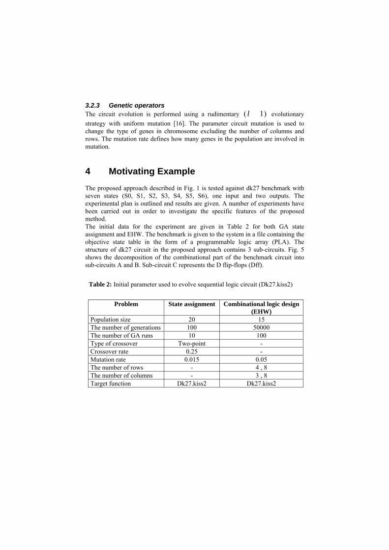
3.2.3 Genetic operators The circuit evolution is performed using a rudimentary )1( +λ evolutionary strategy with uniform mutation [16]. The parameter circuit mutation is used to change the type of genes in chromosome excluding the number of columns and rows. The mutation rate defines how many genes in the population are involved in mutation.
4 Motivating Example The proposed approach described in Fig. 1 is tested against dk27 benchmark with seven states (S0, S1, S2, S3, S4, S5, S6), one input and two outputs. The experimental plan is outlined and results are given. A number of experiments have been carried out in order to investigate the specific features of the proposed method. The initial data for the experiment are given in Table 2 for both GA state assignment and EHW. The benchmark is given to the system in a file containing the objective state table in the form of a programmable logic array (PLA). The structure of dk27 circuit in the proposed approach contains 3 sub-circuits. Fig. 5 shows the decomposition of the combinational part of the benchmark circuit into sub-circuits A and B. Sub-circuit C represents the D flip-flops (Dff).
Table 2: Initial parameter used to evolve sequential logic circuit (Dk27.kiss2)
Problem State assignment Combinational logic design
(EHW) Population size 20 15 The number of generations 100 50000 The number of GA runs 10 100 Type of crossover Two-point - Crossover rate 0.25 - Mutation rate 0.015 0.05 The number of rows - 4 , 8 The number of columns - 3 , 8 Target function Dk27.kiss2 Dk27.kiss2

Dff
in0
in1
in3 in2
inputs
present states
Combinational Circuit
outputs
out1 out2 A C B
Combinational Circuit
Figure 5: Description the circuit parts
Each sub-circuit has been evolved separately using the EHW approach. In Fig. 6, step1 shows the valid encoding for the benchmark by simply replacing the symbols of the states in the SST by the respective state binary code generated by GA. Step2 generates the state assignment. Step 3 partitions the STT of the benchmark circuit into input combinational logic circuit A and output combinational logic circuit B. Once the EHW decomposition is completed, the fully functional circuit can be generated. The obtained experimental results are shown in Fig. 7 (a) and Fig.7 (b). In Fig. 7 (a), the circuit has been evolved using functional set (0-6, 10) and the circuit consists of 11 gates in sub-circuit A, 10 gates in sub-circuit B and 3 D flip-flops in sub-circuit C. The total number of logic gates in assembled circuit is 21 (12 AND, 7 OR, 2 NOT). Fig. 7 (b) shows the circuit evolved using functional set (0-6, 10,15). The most efficient evolved circuit consists of 11 logic gates in sub-circuit A, 5 gates in sub-circuit B and 3 D flip-flops. The total number of logic gates in the circuit is 16 (5 AND, 3 OR, 4 XOR, 4 NOT). The two circuits discussed above illustrate how choosing the functional set of logic gates affects the evolved circuit structures. The functional genes are encoded according to Table 1.
5 Experimental results EHW begins from randomly connected and randomly chosen logic gates and gradually evolves the target functionality. The evolutionary algorithms does not guarantee that 100% functionality circuit of the resulting connections will be achieved in all cases. So, the results reported here are the average from 100 runs. In this section, some experimental results obtained for the MCNC benchmark circuits are given. The experimental results obtained are summarised in Table 3. The table shows the numbers of gates used to evolve each subcircuit after 100 runs. The particular set of logic gates used is fixed in advance, but whether or not any particular gate is used, or how many time a gate is used, is entirely free. The advantage of this approach is that it allows us to synthesis the benchmarks circuit using any set of logic gates. Consequently, it permits the synthesis of compact and unusual circuit structures.

The quality of evolved circuits is defined by the number of logic gates in the circuit. It can be seen from Table 3 that large FSM benchmarks (dk16) is difficult to evolve with one valid solution after 100 runs. These benchmark sets results are compared against SIS [15] for sequential logic synthesis and optimisation. The inputs to SIS are given in state table format and the library is given in genlib format. The output is a netlist of gates for the target technology. It can be seen that in some cases the evolved circuits are much better then the one generated by SIS.
Figure 6: The procedure of generation the *.pla file from the state transition table based on the example of dk27 (Kiss2 benchmark). Step1 shows the initial symbolic State Transition Table, Step2 generates State Assignments using the genetic algorithm and Step 3 generates the PLA files (*.pla) based on the state assignments obtained.
.i 4
.o 3
.p 14
.i 3
.o 2
.p 14
step1
step2
step
3
.e
# number of inputs# number of outputs
# number of states# number of products
.e

(a)
(b)
Figure 7: Evolved dk27 design using (a) functional set (0-6, 10) (b) functional set (0-6, 10,15)
Table 3: Experimental results of extrinsic EHW approach. #in, #out and #stat are the number of inputs, outputs and states respectively. #100 cases is the number of fully functional solutions obtained after 100 runs of GA. The evolved circuits which are more optimal in comparison with SIS[15] are shown in bold.
Specification Estimation of the best SIS [15] Benchmark
.kiss #in #out #stat
Functional set Sub-
circuit A Sub-
circuit B Sub-
circuit C Total
#100 cases
Bbara 4 2 10 0-5, 6, 10,15 32 28 3 60 7 79
Bbtas 2 2 6 2-7, 10, 11, 15, 16 15 4 3 19 24 28
dk15 3 5 4 0,1, 6, 7, 10, 11-16 20 33 2 53 11 66
dk16 2 3 27 0-6, 8, 10, 11, 13, 14, 15 265 40 5 305 1 285
dk27 1 2 7 0- 6, 10, 15 11 5 3 16 28 20 dk512 1 3 14 2-6, 9-14, 16 25 22 4 47 31 58 Lion9 2 1 9 0-6, 10,15 29 21 4 50 7 25
Shiftreg 1 1 8 0-13,15 13 5 3 18 21 9 Tav 4 4 4 0-6, 10,15,16 3 23 2 26 9 29
out1
out2
outputs
inputs Subcircuit BSubcircuit A Subcircuit C
D
Q
QSET
CLR
D
Q
QSET
CLR
D
Q
QSET
CLR
out1
out2
outputsinputs
Subcircuit BSubcircuit A Subcircuit C
D
Q
QSET
CLR
D
Q
QSET
CLR
D
Q
QSET
CLR

6 Conclusions
This paper proposes a new approach to evolve sequential logic circuits. The basic idea of this approach is to use the strength of genetic algorithm at both state assignment and circuit design stages. The standard genetic algorithm has been used in order to identify the optimal state assignment for the given problem. The extrinsic evolvable hardware with rudimentary evolutionary strategy has been applied to synthesise the combinational parts of the sequential circuit. Former results are associated with an evolutionary process in which each evolved FSM benchmark circuit is built and tested in software using computer simulations. The implemented GA is able to design logic circuits with size and complexity, which have not been demonstrated in published work so far on structural genetic and evolutionary algorithms. This automated approach has the added advantage of reduced dependency on the designers’ knowledge and experience. The proposed method to synthesise the sequential logic circuits has been tested on the standard benchmarks. It can be concluded that not enough work has been done in this direction and it is necessary to investigate the evolution of sequential logic circuits more closely. Future work will concentrate on the development of a tool to evolve large state machines without excessive use of memory or CPU time. Further, the optimisation could be tailored to target area, power dissipation or both.
References [1] Darringer, J., et. Al., (1984.) LSS: A system for production of logic
synthesis. IBM J. Res. Develop. vol. 28, pp. 537-545. [2] Almaini A.E.A, (1994) Electronic logic systems”, 3rd Edition, Prentice–
Hall International. [3] Higuchi T., Iba H. and Manderick B. (1994) Evolvable Hardware with
Genetic Lerning in Massively Parallel Artificial Intelligence, eds. H. Kitano, MIT Press, pp. 398-421.
[4] Kalganova T. and Miller J. (1999) Evolving More Efficient Digital Circuits by Allowing Circuit Layout Evolution and Multi-Objective Fitness. Proc. of the First NASA/DoD Workshop on Evolvable Hardware, eds. Stoica A., Keymeulen D. and Lohn J., IEEE Computer Society, pp. 54-63
[5] Thompson A., (1996) Silicon evolution. In Koza, J. R., editor, Proc. of the Int. Conference on Genetic Programming, MIT Press, pp. 444-452.
[6] Kalganova T., (2000) Bidirectional Incremental Evolution in Evolvable Hardware. Proc. of The second NASA/DOD Workshop on Evolvable hardware, Palo Alto, California, USA, Published by IEEE Computer Society.
[7] Kalganova T., J. Miller and T. Fogarty, (1998) Some Aspects of an Evolvable Hardware Approach for Multiple-Valued Combinational Circuit Design. Proc. of the Second International Conference on Evolvable Systems (ICES 98), Springer-Verlag, Lausanne, Switzerland.

[8] Manovit C., C. Aporntewan, and P. Chongstitvatana, (1998) Synthesis of synchronous sequential logic circuits from partial input/output sequence. In Proceedings of International Conference on Evolvable Systems, pp. 98-105,
[9] Thompson A., (1995) Evolving electronic robot controllers that exploit hardware resources. Proc. of the 3rd European Conf. on Artificial Life, vol. 929, pp. 640-656.
[10] Higuchi T., M. Murakawa, M. Iwata, I. Kajitani, W. Liu, and M. Salami (1997) Evolvable Hardware at Function Level" Proc. of the 1997 IEEE Int. Conf. on Evolutionary Computation (ICEC97), pp. 187-192.
[11] Manovit C., C. Aporntewan, and P. Chongstitvatana (1998) Comparison of Technology-Based and State-Based Representations for the Synthesis of Synchronous Sequential Logic from Partial Input/Output Sequence Proc. of Nat. Conf. on Electrical Engineering (EECON-21), Bangkok, Thailand, pp. 210-213
[12] Chongstitvatana P. and C. Aporntewan (1999) Improving Correctness of Finite-State Machine Synthesis from Multiple Partial Input/Output Sequences Proc. of the First NASA/DoD Workshop on Evolvable Hardware, Pasadena, California, pp. 262-266
[12] Koza J., F. Bennett, D. Andre, and M. Keane (1999) Genetic Programming III: Darwinian Invention and Problem Solving. Morgan Kaufman.
[13] Villa T, and A. Sangiovanni-Vincentelli, (1990) NOVA: state assignment of finite state machines for optimal two level logic implementation. IEEE Trans., C-9, pp 905-924.
[14] Yang S., (1991) Logic synthesis and optimisation benchmark user guide version 3.0, MCNC.
[15] Sentovich E. M., K. J. Singh, L. Lavagno, C. Moon, R. Murgai, A. Saldanha, H. Savoj, et al., (1992) SIS. A System for Sequential Circuit Synthesis. Tech. Rep. UCB/ERL M92/41,Electronics Research Lab, CA 94720, Univ. of California, Berkeley.
[16] Kalganova T., J. Miller, (1999) Evolving More Efficient Digital Circuits by Allowing Circuit Layout Evolution and Multi-Objective Fitness. Proc. of the First NASA/DoD Workshop on Evolvable Hardware. eds. Stoica A., Keymeulen D. and Lohn J., IEEE Computer Society, pp. 54-63
[17] Angeline P.J., D.B. Fogel and L.J. Fogel (1996) A comparison of self-adaptation methods for finite-state machines in a dynamic environment. Proc. of the 5th Annual Conf. On Evolutionary Programming, pp.441-449.
[18] Fogel L.J. Autonomous automata. in Industrial Research, 4 :14-19, 1962.