Extreme Networks® Wireless Management Suite Reference Guide
191
Extreme Networks, Inc. 3585 Monroe Street Santa Clara, California 95051 (888) 257-3000 (408) 579-2800 http://www.extremenetworks.com Published: March 2011 Part Number: 100356-00 Rev 03 Extreme Networks ® Wireless Management Suite Reference Guide
-
Upload
duongkhanh -
Category
Documents
-
view
227 -
download
3
Transcript of Extreme Networks® Wireless Management Suite Reference Guide

Extre3585Santa(888)(408)http:/PubliPart N
Extreme Networks® Wireless Management Suite Reference Guide
me Networks, Inc. Monroe Street Clara, California 95051 257-3000 579-2800/www.extremenetworks.comshed: March 2011umber: 100356-00 Rev 03

2
AccessAdapt, Alpine, Altitude, BlackDiamond, EPICenter, ExtremeWorks Essentials, Ethernet Everywhere, Extreme Enabled, Extreme Ethernet Everywhere, Extreme Networks, Extreme Standby Router Protocol, Extreme Turbodrive, Extreme Velocity, ExtremeWare, ExtremeWorks, ExtremeXOS, Go Purple Extreme Solution, ExtremeXOS ScreenPlay, ReachNXT, Sentriant, ServiceWatch, Summit, SummitStack, Triumph, Unified Access Architecture, Unified Access RF Manager, UniStack, the Extreme Networks logo, the Alpine logo, the BlackDiamond logo, the Extreme Turbodrive logo, the Summit logos, and the Powered by ExtremeXOS logo are trademarks or registered trademarks of Extreme Networks, Inc. or its subsidiaries in the United States and/or other countries.
sFlow is a registered trademark of InMon Corporation.
Specifications are subject to change without notice.
All other registered trademarks, trademarks, and service marks are property of their respective owners.
© 2011 Extreme Networks, Inc. All Rights Reserved.
Extreme Networks Wireless Management Suite Reference Guide

Extreme
Table of Contents
Chapter 1: About This Guide ..................................................................................................................... 7Introduction..............................................................................................................................................................7Additional Documentation.......................................................................................................................................7Document Conventions............................................................................................................................................7Notational Conventions ...........................................................................................................................................8
Chapter 2: Overview ................................................................................................................................... 9About WMS.............................................................................................................................................................9
Supported Infrastructure ...................................................................................................................................9Features and Functionality.....................................................................................................................................10
Summit WMScanner Site Planning ................................................................................................................10WIPS Sensor Support .....................................................................................................................................11My Network....................................................................................................................................................12My Groups ......................................................................................................................................................14Administration ................................................................................................................................................15Upgradable Software ......................................................................................................................................19System Configuration .....................................................................................................................................20Network View.................................................................................................................................................20Mesh Visualization .........................................................................................................................................20Diagnostic Support .........................................................................................................................................20Dashboards .....................................................................................................................................................20Notification Templates ...................................................................................................................................21Import/Export .................................................................................................................................................21
Chapter 3: Installing and Licensing WMS.............................................................................................. 23WMS Installation ...................................................................................................................................................23
System Components .......................................................................................................................................23System Requirements .....................................................................................................................................23Assumptions ...................................................................................................................................................23Installing WMS in a Windows 2003 Server Environment .............................................................................24Uninstalling WMS..........................................................................................................................................28Getting a License Key ....................................................................................................................................29
Chapter 4: Planning Your Network Deployment ................................................................................... 31Installing Summit WMScanner from WMS ..........................................................................................................31
Exporting Site Information from Summit WMScanner into WMS................................................................32Importing WMS Data into Summit WMScanner ...........................................................................................35
Chapter 5: My Network Configuration................................................................................................... 37Summary................................................................................................................................................................39
Dashboard .......................................................................................................................................................40DeviceList.......................................................................................................................................................49Radios .............................................................................................................................................................50
Network View........................................................................................................................................................51
Networks Wireless Management Suite Reference Guide 3

Table of Contents
4
Controls ..........................................................................................................................................................52Layout .............................................................................................................................................................54View Controls.................................................................................................................................................56Search/Filter Nodes ........................................................................................................................................58
RF View.................................................................................................................................................................58Saving a Site ...................................................................................................................................................59RF and Site Views ..........................................................................................................................................59Showing MUs .................................................................................................................................................61
Faults......................................................................................................................................................................63Alarms.............................................................................................................................................................63Events .............................................................................................................................................................66
Reports ...................................................................................................................................................................67Viewing Pre-Defined Reports.........................................................................................................................67Live Reporting ................................................................................................................................................71
Configuration .........................................................................................................................................................72Compliance .....................................................................................................................................................73Templates........................................................................................................................................................79Backup Restore...............................................................................................................................................86
Firmware ................................................................................................................................................................92Diagnostics.............................................................................................................................................................97
Troubleshooting WLANs ...............................................................................................................................97Troubleshooting Access Points(AP35XX or AP47XX)...............................................................................102Troubleshooting Adopted Access Points......................................................................................................106Troubleshooting Mobile Units......................................................................................................................110
Chapter 6: My Groups ............................................................................................................................ 113About WMS Groups ............................................................................................................................................114
Adding a Group ............................................................................................................................................115Editing an Existing Group ............................................................................................................................118Deleting a Group...........................................................................................................................................119
Chapter 7: WMS Administration........................................................................................................... 121User Management ................................................................................................................................................121
Adding a New User ......................................................................................................................................122Editing the Attributes of an Existing User....................................................................................................123Deleting an Existing User.............................................................................................................................124Site Management ..........................................................................................................................................125Site Configuration.........................................................................................................................................125Relay Server Configuration ..........................................................................................................................131
Device Management ............................................................................................................................................134Managing Devices ........................................................................................................................................135Deleting Devices...........................................................................................................................................136Moving Devices............................................................................................................................................137Planning Devices ..........................................................................................................................................138
Security Management ..........................................................................................................................................139Adding a WIPS Server Configuration ..........................................................................................................140Editing the Properties of a WIPS Server ......................................................................................................141Deleting a WIPS Server................................................................................................................................142
Network Discovery ..............................................................................................................................................142IP Ranges ......................................................................................................................................................143
Extreme Networks Wireless Management Suite Reference Guide

Table of Contents
SNMP Profiles ..............................................................................................................................................150Network Monitoring ............................................................................................................................................154Alarm Policies......................................................................................................................................................155Notification Templates ........................................................................................................................................157
Email Configurations....................................................................................................................................158SNMP Trap Forwarding ...............................................................................................................................160
Configuration Templates .....................................................................................................................................163Editing an Existing Configuration Template................................................................................................164Deleting a Configuration Template ..............................................................................................................167
Firmware Images .................................................................................................................................................167Editing a Firmware Image ............................................................................................................................168Deleting a Firmware Image ..........................................................................................................................169Importing a Firmware Image ........................................................................................................................169
Job Status .............................................................................................................................................................170Database Management .........................................................................................................................................172
Database Backup ..........................................................................................................................................172Database Restoration ....................................................................................................................................174Database Details ...........................................................................................................................................175Database Purge .............................................................................................................................................176
System Configuration ..........................................................................................................................................177Logging................................................................................................................................................................178
Saving a Log File..........................................................................................................................................179Editing a Log File .........................................................................................................................................179
Import/Export.......................................................................................................................................................180Importing User Information..........................................................................................................................181Exporting User Information..........................................................................................................................182Importing Site or Relay Server Information.................................................................................................182Exporting Site or Relay Server Information.................................................................................................183Importing a WIPS Server..............................................................................................................................183Exporting a WIPS Server..............................................................................................................................184Importing an IP Range or SNMP Profile......................................................................................................184Exporting an IP Range or SNMP Profile......................................................................................................185Importing Email Notification Templates and SNMP Trap Destinations......................................................185Exporting Email Notification Templates and SNMP Trap Destinations......................................................186License Management ....................................................................................................................................186
About ...................................................................................................................................................................188
Appendix A: Customer Support............................................................................................................. 189Registration ..........................................................................................................................................................189Documentation.....................................................................................................................................................189
Extreme Networks Wireless Management Suite Reference Guide 5

Table of Contents
6
Extreme Networks Wireless Management Suite Reference Guide
1 About This Guide
IntroductionThis guide provides information about using the Extreme Networks® Wireless Management Suite (WMS).
NOTE
Screens and windows pictured in this guide are samples and can differ from actual screens.
Additional Documentation● Summit® WMScanner User Guide - WMScanner is a software package that enables you to layout,
model, and measure 802.11an, and 802.11bgn networks. Building facilities and campus environments can be quickly modeled using intuitive menus which guide you step-by-step. Using WMScanner you can place access points and predict signal coverage during the WLAN design phase.
Document ConventionsThe following conventions are used in this document to draw your attention to important information:
NOTE
Indicate tips or special requirements.
CAUTION
Indicates conditions that can cause equipment damage or data loss.
WARNING!
Indicates a condition or procedure that could result in personal injury or equipment damage.
Extreme Networks Wireless Management Suite Reference Guide 7

About This Guide
8
Notational ConventionsThe following additional notational conventions are used in this document:
● Italics are used to highlight the following:
● Chapters and sections in this and related documents
● Dialog box, window and screen names
● Drop-down list and list box names
● Check box and radio button names
● Icons on a screen.
● GUI text is used to highlight the following:
● Screen names
● Menu items
● Button names on a screen.
● bullets (•) indicate:
● Action items
● Lists of alternatives
● Lists of required steps that are not necessarily sequential
● Sequential lists (e.g., those that describe step-by-step procedures) appear as numbered lists.
Extreme Networks Wireless Management Suite Reference Guide

2 Overview
The Extreme Networks Wireless Management Suite (WMS) is an intuitive, browser-based, network management solution for management, troubleshooting and monitoring. RF heat maps display system performance. Users can manage hundreds of sites (and thousands of devices), view the status and location of wireless infrastructure devices and clients, search for specific pieces of equipment, troubleshoot network issues, generate reports and export raw data.
WMS simplifies the management of your RF network with an intuitive Web-based user interface. Network administrators with little or no RF experience can manage their Wi-Fi networks within a few hours of installing WMS.
About WMSWMS is a stand-alone Windows 2003 Server application providing users with the functionality to research and define the physical design and intended performance of their RF infrastructure.
WMS is Extreme Networks Enterprise Wireless LAN network management solution. WMS provides a single console from which you can monitor and analyze wireless networks using not only the WMS resident interface feature set, but the robust feature sets of the Summit WMScanner application. Summit WMScanner is bundled with WMS and is used as the tool for network device deployment, building formatting and site surveys
WMS and Summit WMScanner provide a highly integrated toolset for network design, management and survey. Summit WMScanner allows you to import building floorplans and measure performance using its site survey capabilities. Summit WMScanner allows WMS to define new coverage areas, generate updated floor plans and display device locations.
Supported InfrastructureExtreme Networks WMS supports each of the following enterprise WLAN devices as one licensed device:
● Summit WM3400 WLAN Controller
● Summit WM3600 WLAN Controller
● Summit WM3700 WLAN Controller
● Altitude 3500 Series Access Point
● Altitude 4600 Series Access Point
● Altitude 4700 Series Access Point
NOTE
Once you exceed the number of devices supported by your license, you must increase the number of devices supported by the license to legally use WMS.
Extreme Networks Wireless Management Suite Reference Guide 9

Overview
10
Features and FunctionalityWMS is positioned as Extreme Networks Enterprise WLAN network management and RF analysis tool, offering the most desirable feature set previously available only across multiple (individually licensed) applications. WMS supports the following features and functionality:
● Summit WMScanner Site Planning on page 10
● WIPS Sensor Support on page 11
● My Network on page 12
● My Groups on page 14
● Administration on page 15
● Upgradable Software on page 19
● System Configuration on page 20
● Network View on page 20
● Diagnostic Support on page 20
● Dashboards on page 20
● Notification Templates on page 21
● Import/Export on page 21
Summit WMScanner Site PlanningSummit WMScanner enables the layout, modeling and measurement of 802.11an and 802.11bgn networks. Summit WMScanner allows CAD drawings (and other formats) to be imported into the application. However, it does not model the RF network based upon AP placement in the floorplan. Administrators have to perform a manual site survey of the deployment area to identify problem areas and performance of the network.
NOTE
Before using WMS as your WLAN network management solution, use Summit WMScanner to locate areas of optimal RF performance and plan and deploy network devices. Once site drawings have been created in Summit WMScanner, site and device information can be saved and shared between WMS and Summit WMScanner as configuration activities warrant.
WMS and Summit WMScanner InteroperationSummit WMScanner is bundled with WMS on the product CDROM and is installed and licensed with WMS. Summit WMScanner does not function autonomously within WMS, and has the ability to share data with WMS for those devices deployed within a Summit WMScanner drawing. Summit WMScanner supports Altitude 3500, Altitude 4600, Altitude 4700, Summit WM3400, Summit WM3600 and Summit WM3700 model devices.
NOTE
When Summit WMScanner is installed to your PC, you can use Summit WMScanner for 14 days without a license. Once expired, Summit WMScanner can only be activated again with a valid license. For assistance, go tohttps://esupport.extremenetworks.com.
Extreme Networks Wireless Management Suite Reference Guide

Once a WMS defined device has been placed in a Summit WMScanner drawing, device attributes can be modified using the Summit WMScanner interface. Each Summit WMScanner site drawing is developed to support the actual physical dimensions of a specific radio coverage area. As a result, device location coordinates can be accurately assessed using X, Y and Z coordinates on the site drawing.
A Summit WMScanner session can be opened and saved directly from WMS. Summit WMScanner sessions invoked from WMS are authenticated by Summit WMScanner before deployed. Summit WMScanner can save and export device configurations back to WMS that include IP address, transmit power, channel number, antenna pattern and orientation. Controller and AP information is also re-populated in WMS using information provided by Summit WMScanner.
Modeling a Wireless Network with Summit WMScannerThe WLAN design process begins by modeling your deployment environment in Summit WMScanner. This can be achieved through manually defining the building layout or by importing existing building information from a variety of sources. Import formats include CAD files, scanned images, and digital pictures. Next, you consider the environmental context by associating walls within the facility map with material types (such as sheetrock or brick) from a library of common building materials. Summit WMScanner is designed to provide advanced network modeling and verification utilities that allow a user to visually display network coverage and performance within a site-specific map of their deployment environment. Using Summit WMScanner, network modelers can adjust their deployment design to address identified coverage holes.
For information on using Summit WMScanner, refer to the Summit WMScanner User Guide available athttp://www.extremenetworks.com/go/documentation.
WIPS Sensor SupportWMS permits the optional deployment of the Wireless Intrusion Protection Software (WIPS), a third party wireless security product by Motorola. as an application launched from within WMS. WIPS is separately installed and launched as an independently licensed application within the WMS interface.
WIPS protects your wireless network, mobile devices and traffic from attacks and unauthorized access. WIPS provides tools for standards compliance and around-the-clock 802.11a/b/g/n wireless network security in a distributed environment. WIPS allows administrators to identify and accurately locate attacks, rogue devices and network vulnerabilities in real time and permits both a wired and wireless lockdown of wireless device connections upon acknowledgement of a threat.
WMS has the ability to launch WIPS and receive SNMP traps generated by the WIPS server. Therefore, a WMS maintained site can be secured by the device detection capabilities resident to the WIPS application. WMS also has the ability to define and deploy sensors used by WIPS as detecting radios to locate the position of a potentially hostile device or devices with excessive association/authentication requests.
For more information, see “Security Management” on page 139.
For more information on using WIPS, refer the WIPS Users Guide, available athttp://support.symbol.com/support/product/manuals.do.
Extreme Networks Wireless Management Suite Reference Guide 11
Overview
12
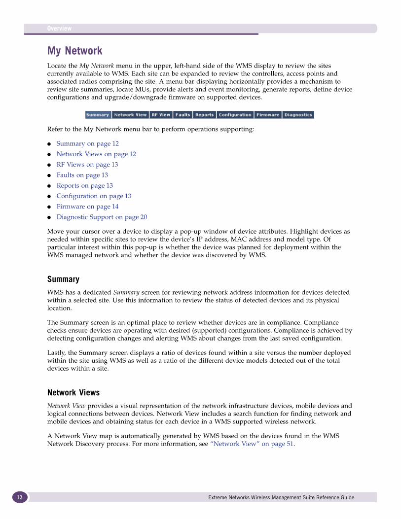
My NetworkLocate the My Network menu in the upper, left-hand side of the WMS display to review the sites currently available to WMS. Each site can be expanded to review the controllers, access points and associated radios comprising the site. A menu bar displaying horizontally provides a mechanism to review site summaries, locate MUs, provide alerts and event monitoring, generate reports, define device configurations and upgrade/downgrade firmware on supported devices.
Refer to the My Network menu bar to perform operations supporting:
● Summary on page 12
● Network Views on page 12
● RF Views on page 13
● Faults on page 13
● Reports on page 13
● Configuration on page 13
● Firmware on page 14
● Diagnostic Support on page 20
Move your cursor over a device to display a pop-up window of device attributes. Highlight devices as needed within specific sites to review the device’s IP address, MAC address and model type. Of particular interest within this pop-up is whether the device was planned for deployment within the WMS managed network and whether the device was discovered by WMS.
SummaryWMS has a dedicated Summary screen for reviewing network address information for devices detected within a selected site. Use this information to review the status of detected devices and its physical location.
The Summary screen is an optimal place to review whether devices are in compliance. Compliance checks ensure devices are operating with desired (supported) configurations. Compliance is achieved by detecting configuration changes and alerting WMS about changes from the last saved configuration.
Lastly, the Summary screen displays a ratio of devices found within a site versus the number deployed within the site using WMS as well as a ratio of the different device models detected out of the total devices within a site.
Network ViewsNetwork View provides a visual representation of the network infrastructure devices, mobile devices and logical connections between devices. Network View includes a search function for finding network and mobile devices and obtaining status for each device in a WMS supported wireless network.
A Network View map is automatically generated by WMS based on the devices found in the WMS Network Discovery process. For more information, see “Network View” on page 51.
Extreme Networks Wireless Management Suite Reference Guide
RF ViewsUse the RF View tab to define how coverage areas display within the WMS console. The RF View tab also provides a means of displaying MU association patterns. For more information, see “RF View” on page 58.
FaultsThe Faults feature provides alerting and event monitoring by displaying alerts and network event summaries (as dashboard views) to identify devices that may be in distress. Reports can be optionally generated based on different alert criteria.
The Faults screen is partitioned into two tabs supporting the following:
● Alarms on page 63
● Events on page 66
The Alarms functionality provides an automated action at various levels of the event flow. Alarm policies are defined using a configuration file based on device type. The WMS alarm correlator defines the logic for generating policy-based alarms and alerts by reading policies from a configuration file for the affected device.
Refer to the Events tab to review a summary of events with appropriate color codes. Network events are displayed as red, orange, blue and green icons for critical error, major error, minor error, warning and clear states. Informational states may not need to be addressed immediately, whereas error states may require immediate corrective action.
For more information, see “Faults” on page 63.
ReportsWMS contains a list of pre-defined Reports relevant to the device models supported. When a user selects a device, a list of applicable pre-defined reports is available for that device family. The user can also select reports for a specific time period (with a beginning and ending date) to further refine the content of the report in respect to the reporting interval.
The data collected by WMS can be reported in either a raw-data or graphical format. The data collected within a WMS report is periodically polled by the MIB structures supporting WMS device monitoring and data collection activities.
The WMS reporting feature allows you to select a device model, display its associated device count and collect its MIB configuration attribute(s). Reviewing the device configuration attributes in real-time affords the user the advantage of assessing how the device reports network events based on the parameters and threshold values set for the device.
For more information, see “Reports” on page 67.
ConfigurationThe Configuration module provides the ability to configure supported Extreme Networks infrastructure devices. The feature also enables you to take corrective action if changes have occurred that could negatively impact a device’s configuration. SNMP is the protocol used for communication between WMS and a target device. Configurations can be backed up (archived) and restored to relevant devices as needed.
Extreme Networks Wireless Management Suite Reference Guide 13
Overview
14
The Configuration screen is partitioned into three tabs supporting the following:
● Compliance on page 73
● Templates on page 79
● Backup Restore on page 86
Refer to the Compliance tab to conduct periodic checks for device configuration compliance and (if necessary) resolve non-compliant configurations. The compliance function ensures devices are operating with desired configurations. Compliance is achieved by detecting configuration changes and alerting WMS about the change from the last WMS saved configuration.
Compliance has been enhanced to support groups of devices, as opposed to individual devices. Now configuration checks and resolutions determinations can be made at the group level with a big savings in time invested.
A Template is a configuration file that can be applied to a specific device model. Templates have placeholders for providing variable values for either a full or partial device configuration. The placeholders follow a syntax convention defined by WMS.
NOTE
For use case information on how templates are created and installed on devices, see “Creating a Template” on page 80.
Use the Backup/Restore facility to backup templates (configuration files) conveniently from one location within WMS. Once saved in the WMS repository, configurations can be restored to the same device model from which originally extracted. The WMS backup and restore facility compares backup configurations with current configurations. This comparison can serve as the criteria for restoring a backup configuration to the device originally submitting the backup file.
For more information, see “Configuration” on page 72.
FirmwareUse the WMS Firmware feature for upgrading/downgrading firmware on supported devices. WMS can apply a firmware image to a single device or a group of homogenous (same model) devices.
Schedule a firmware updates at a user defined interval. Firmware installations involve copying a firmware binary file to an FTP or TFTP Relay Server. Device firmware files are quite large, so to minimize network bandwidth, files are copied to the respective site’s Relay Server(s).
For more information, see “Firmware” on page 92.
My GroupsA group is a set of devices managed collectively within WMS. These groups can be viewed and managed collectively from the My Groups menu. Groups can be heterogeneous or homogeneous. Heterogeneous groups contain devices of different device types, whereas homogeneous groups contain devices of the same device type. A wizard configuration approach as been included for creating and editing groups. The wizard significantly reduces the time needed to administer multiple groups.
Extreme Networks Wireless Management Suite Reference Guide
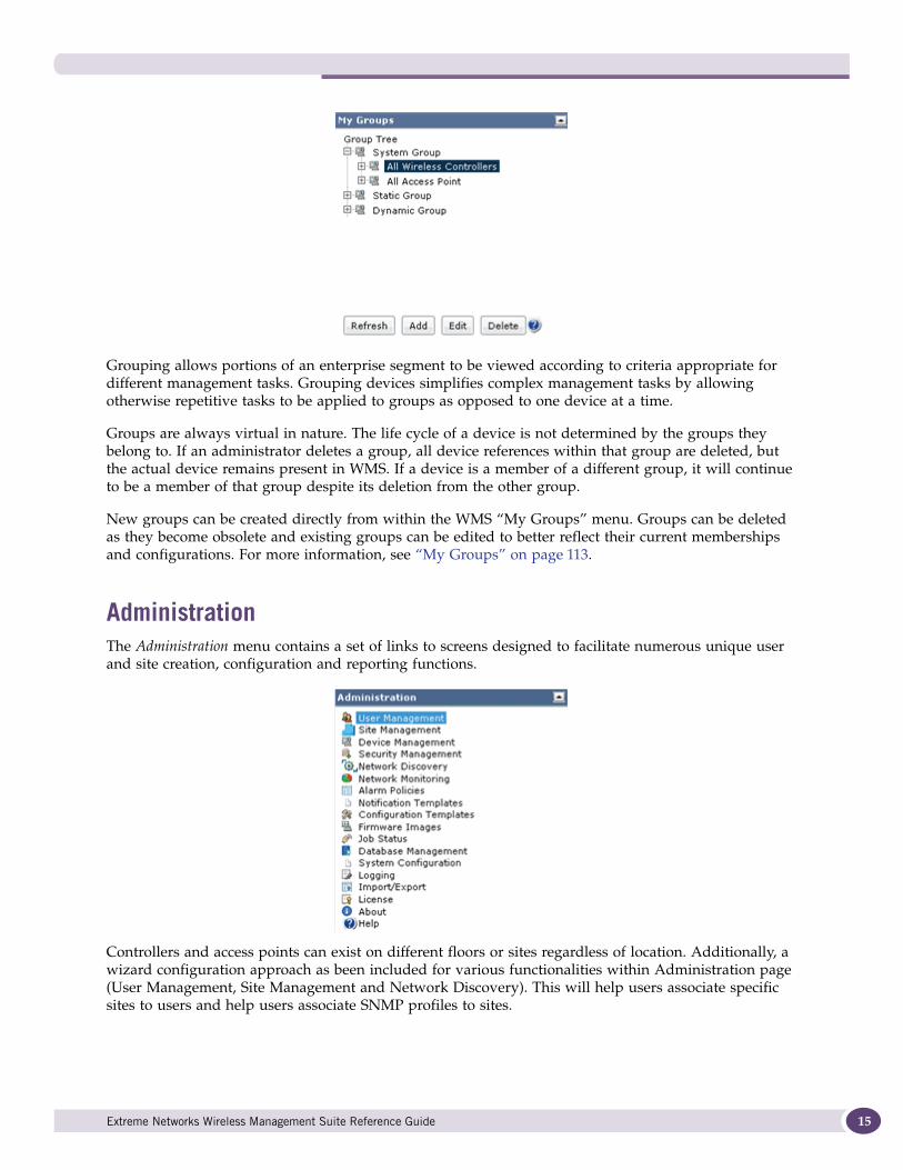
Grouping allows portions of an enterprise segment to be viewed according to criteria appropriate for different management tasks. Grouping devices simplifies complex management tasks by allowing otherwise repetitive tasks to be applied to groups as opposed to one device at a time.
Groups are always virtual in nature. The life cycle of a device is not determined by the groups they belong to. If an administrator deletes a group, all device references within that group are deleted, but the actual device remains present in WMS. If a device is a member of a different group, it will continue to be a member of that group despite its deletion from the other group.
New groups can be created directly from within the WMS “My Groups” menu. Groups can be deleted as they become obsolete and existing groups can be edited to better reflect their current memberships and configurations. For more information, see “My Groups” on page 113.
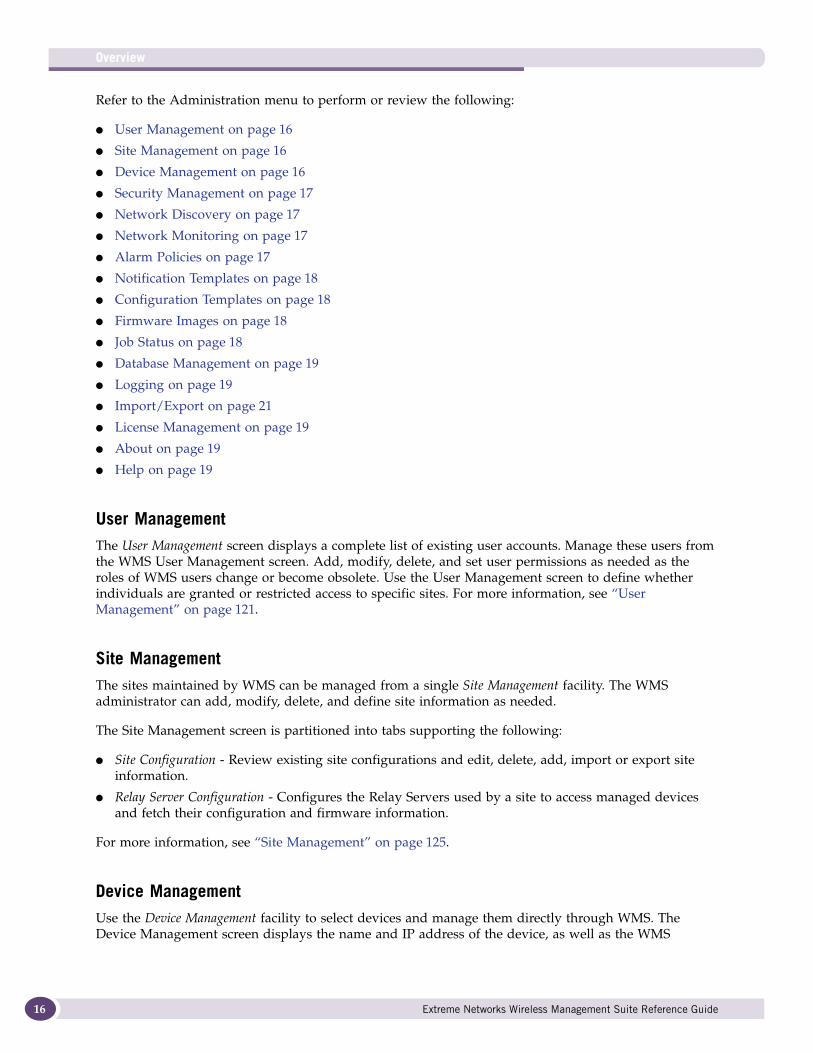
AdministrationThe Administration menu contains a set of links to screens designed to facilitate numerous unique user and site creation, configuration and reporting functions.
Controllers and access points can exist on different floors or sites regardless of location. Additionally, a wizard configuration approach as been included for various functionalities within Administration page (User Management, Site Management and Network Discovery). This will help users associate specific sites to users and help users associate SNMP profiles to sites.
Extreme Networks Wireless Management Suite Reference Guide 15
Overview
16
Refer to the Administration menu to perform or review the following:
● User Management on page 16
● Site Management on page 16
● Device Management on page 16
● Security Management on page 17
● Network Discovery on page 17
● Network Monitoring on page 17
● Alarm Policies on page 17
● Notification Templates on page 18
● Configuration Templates on page 18
● Firmware Images on page 18
● Job Status on page 18
● Database Management on page 19
● Logging on page 19
● Import/Export on page 21
● License Management on page 19
● About on page 19
● Help on page 19
User ManagementThe User Management screen displays a complete list of existing user accounts. Manage these users from the WMS User Management screen. Add, modify, delete, and set user permissions as needed as the roles of WMS users change or become obsolete. Use the User Management screen to define whether individuals are granted or restricted access to specific sites. For more information, see “User Management” on page 121.
Site ManagementThe sites maintained by WMS can be managed from a single Site Management facility. The WMS administrator can add, modify, delete, and define site information as needed.
The Site Management screen is partitioned into tabs supporting the following:
● Site Configuration - Review existing site configurations and edit, delete, add, import or export site information.
● Relay Server Configuration - Configures the Relay Servers used by a site to access managed devices and fetch their configuration and firmware information.
For more information, see “Site Management” on page 125.
Device ManagementUse the Device Management facility to select devices and manage them directly through WMS. The Device Management screen displays the name and IP address of the device, as well as the WMS
Extreme Networks Wireless Management Suite Reference Guide
managed site each device was detected in. An indicator displays defining whether the device is to be managed by WMS or if no device management is planned by WMS.
For more information, see “Device Management” on page 134.
Security ManagementUse the WMS Security Management feature to manage (edit, delete and add) Wireless Intrusion Protection System (WIPS) servers available to WMS. Once the attributes of a WIPS server is defined, a user can launch the server from WMS. If WIPS is already installed on the client machine, WMS launches the WIPS application and uses an auto-login feature with existing login credentials for that WIPS server. WMS supports the addition of multiple WIPS Servers within a WMS default site.
For more information, see “Security Management” on page 139.
Network DiscoveryUse Network Discovery resources to create search criteria used in the device detection and discovery process. Once defined, conduct a search to find devices meeting the search criteria.
The Network Discovery screen is partitioned into tabs supporting the following configuration activities:
● IP Range - Sets parameters for device and network discovery. Network Discovery uses an associated SNMP profile as search criteria to discover and connect to devices.
● SNMP Profiles - Before you can find devices, define search criteria. WMS uses SNMP to discover devices. Create SNMP profiles for the sites and devices. WMS supports both SNMP v2C and v3 when discovering devices.
The WMS Discovery module is enhanced to support scheduled discovery. Scheduled discovery enables you to trigger discovery on a regular basis automatically. This feature is especially useful when deploying using a phased approach. Now, you can still log into WMS and manually trigger discovery and automatically discover devices using a planned discovery interval.
For more information, see “Network Discovery” on page 142.
Network MonitoringUse the Network Monitoring screen to monitor devices within sites managed by WMS. The Network Monitoring feature uses a SNMP browser interface to manage the individual properties of devices. Each device model has an associated data collection profile which identifies the list of attributes collected periodically from the device.
For more information, see “Network Monitoring” on page 154.
Alarm PoliciesRefer to the Alarm Policies screen to view the total number of alarms and events impacting a listed device. Use this information to compare the total events occurring for a device versus the number of selected events for that device. This information can also be weighed (for significance) against the total number of devices associated. The Faults tab includes a graphical breakdown of event severity and category.
Extreme Networks Wireless Management Suite Reference Guide 17
Overview
18
For more information, see “Alarm Policies” on page 155.
Notification TemplatesNotification Templates enable the creation of Email and SNMP trap policies that can be assigned to a site. A single policy can be used across multiple sites and for multiple events. Policies save time by eliminating the need to create a single template for each event. WMS generated events (which can be converted into alarms) can forwarded via Email or SNMP trap.
For more information, see “Notification Templates” on page 157.
Configuration TemplatesRefer to the Configuration screen to modify or delete configuration templates. A template is a configuration file that can be applied to a specific device model. Templates have placeholders for providing variable values for either a full or partial device configurations. Variable files supply unique configuration values within in the template. Create variable files as required to perform configuration updates through the WMS console.
For more information, see “Configuration Templates” on page 163.
NOTE
For use case information on how templates are created and installed on devices, see “Creating a Template” on page 80
Firmware ImagesUsing the Firmware feature, WMS can apply a firmware image to a single device or a group of homogenous (same model) devices.
Provide your own schedule to begin firmware jobs at specific intervals. Firmware installations involve copying a firmware binary file to an FTP or TFTP Relay Server. Device firmware images are quite large, so to minimize network bandwidth, the files are copied to the respective site’s Relay Server(s). The file can then be used any number of times for all the devices belonging to that site.
Importing and archiving device firmware to the WMS Server is useful when devices (with obsolete firmware) are added and require an upgrade. Once imported to the WMS server, import firmware to a supported device.
For more information, see “Firmware Images” on page 167.
Job StatusRefer to the WMS Job Status facility to view the firmware and configuration jobs (files) created on various devices and models. The Job Status screen provides a single location to view the changes pushed onto devices and captures the time the updates occurred. As you can envision, the Job Status screen is central to good WMS housekeeping, as it represents a means of analyzing file management transactions from one location.
For more information, see “Job Status” on page 170.
Extreme Networks Wireless Management Suite Reference Guide
Database ManagementThe WMS Database Management facility manages the WMS database. WMS uses a database to archive and manage sites, users and configurations. Additionally, create a database backup image file that can restore the WMS server configuration to its current state. Creating a backup image is a recommended practice to periodically ensure WMS maintains device assets and data can be returned to their original state (at the time the backup is made.). Periodically purge (remove) backups as WMS nears its 5 GB storage capacity.
NOTE
When the WMS database is restored from a backup, the current state of the database is completely erased before the backup image is applied. When restoring the WMS database, all users are logged off and the WMS process is shut down and then brought back up.
For more information, see “Database Management” on page 172.
LoggingWMS generates log files and stores them internally within the WMS Server These files are used for capturing server activity and errors that may occur. A file’s logging level can be modified to revise the amount of information and detail captured in the event log.
For more information, see “Logging” on page 178.
License ManagementWMS uses a License Management facility to assess the status of your license and manage the licenses available to this version of WMS. A valid license allows you to legally use the product (for a specified number of radio devices) and potentially add extra licenses to extend WMS to support more sites and devices when needed.
For more information, see “License Management” on page 186.
About
Refer to the About screen for WMS versioning and build information that may be required if contacting support.
Help
Refer to the Help for help with this page.
Upgradable SoftwareWMS supports software upgrades without data loss. The installer archives data and populates it within the installation.
Extreme Networks Wireless Management Suite Reference Guide 19
Overview
20
If the upgrade encounters an error, it can revert back to its original state without loosing data. The installer does not support a downgrade. An upgrade must be on the same system where the legacy version was detected.
System ConfigurationWMS enables you to define how sites are displayed within the site tree as they are added. When adding multiple parameters to a site name, WMS allows you to separate them with either a dot (.) or a hyphen (-).
For more information, see “System Configuration” on page 177.
Network ViewNetwork View provides a representation of the network infrastructure devices, mobile devices and logical connections between devices. Network View includes a search function for finding network and mobile devices and obtaining status for each device in a WMS supported wireless network.
A Network View map is automatically generated by WMS based on the devices found in the WMS Network Discovery process.
For more information, see “Network View” on page 51.
Mesh VisualizationMesh Visualization allows users to visually view Mesh deployments. WMS periodically queries the controller to obtain details about the Mesh network.
For more information, see “Mesh Visualization” on page 53.
Diagnostic SupportThe Diagnostics feature is to assist users in troubleshooting potential problems impacting WLANs, access point radios and mobile units client devices. The diagnostics feature allows you to review and compare throughput and performance statistics intelligently and help determine the load balance of device radios and WLAN configurations. The diagnostic tab uses a wizard-based interface for troubleshooting common network problems. For more information, see “Diagnostics” on page 97.
DashboardsA Dashboard function is one of the Summary screen’s sub functions. The Dashboard is a significant enhancement to the Summary functionality, allowing administrators to make global (all sites), site specific and device specific inquiries into the performance, network addressing and device health of all the components within a licensed WMS deployment. For more information, refer to “Dashboard” on page 40.
Extreme Networks Wireless Management Suite Reference Guide

Notification TemplatesAn administrator can view, add, modify, delete, and define Email and SNMP notification templates. When an error occurs on a WMS managed device, the information is submitted to an administrator through a WMS defined Email address. WMS uses notification templates to convey this information. Additionally, SNMP traps can be forwarded to upstream network management systems on any event reported in the WMS console. For information on creating notification templates, see “Notification Templates” on page 157.
Import/ExportA Import/Export screen enables WMS administrators to import/export information relating to User Management, Site Management, Security Management, Network Discovery and Notification Templates from one location. The import/export functionality has been consolidated within one screen, for all administrative functions, to better enable administrators the ability to perform file management without having to navigate to numerous places within WMS.
Extreme Networks Wireless Management Suite Reference Guide 21

Overview
22
Extreme Networks Wireless Management Suite Reference Guide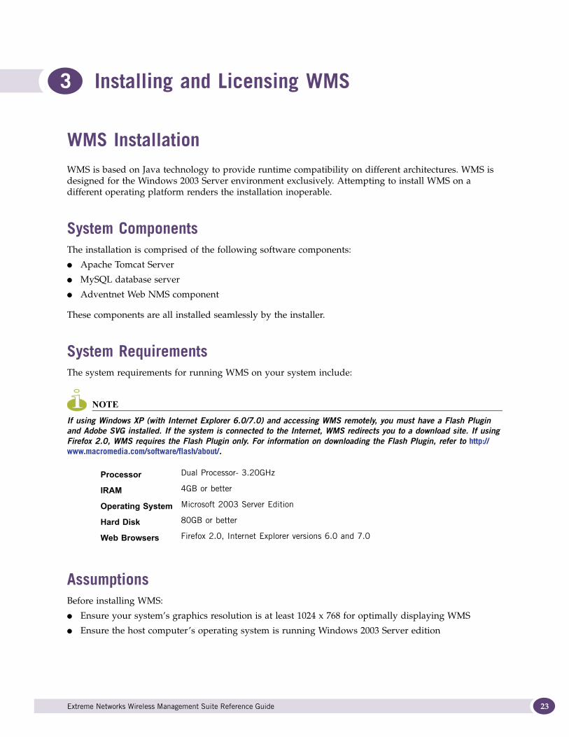
3 Installing and Licensing WMS
WMS InstallationWMS is based on Java technology to provide runtime compatibility on different architectures. WMS is designed for the Windows 2003 Server environment exclusively. Attempting to install WMS on a different operating platform renders the installation inoperable.
System ComponentsThe installation is comprised of the following software components:
● Apache Tomcat Server
● MySQL database server
● Adventnet Web NMS component
These components are all installed seamlessly by the installer.
System RequirementsThe system requirements for running WMS on your system include:
NOTE
If using Windows XP (with Internet Explorer 6.0/7.0) and accessing WMS remotely, you must have a Flash Plugin and Adobe SVG installed. If the system is connected to the Internet, WMS redirects you to a download site. If using Firefox 2.0, WMS requires the Flash Plugin only. For information on downloading the Flash Plugin, refer to http://www.macromedia.com/software/flash/about/.
AssumptionsBefore installing WMS:
● Ensure your system’s graphics resolution is at least 1024 x 768 for optimally displaying WMS
● Ensure the host computer’s operating system is running Windows 2003 Server edition
Processor Dual Processor- 3.20GHz
IRAM 4GB or better
Operating System Microsoft 2003 Server Edition
Hard Disk 80GB or better
Web Browsers Firefox 2.0, Internet Explorer versions 6.0 and 7.0
Extreme Networks Wireless Management Suite Reference Guide 23
Installing and Licensing WMS
24
● Ensure you have Web connectivity (during the actual installation). Extreme Networks recommends using Mozilla FireFox (version2.5.x) with WMS and Internet Explorer (version 6 or higher) with Summit WMScanner.
● When accepting the terms of the License Agreement, you are agreeing to install and use not only WMS, but each application installed and invoked by the installer and application.
Installing WMS in a Windows 2003 Server EnvironmentTo install WMS in a Windows 2003 Server environment:
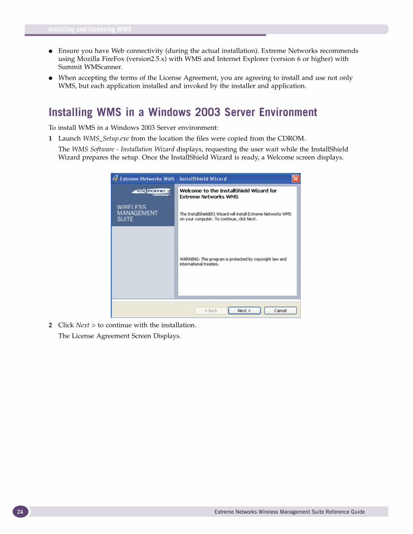
1 Launch WMS_Setup.exe from the location the files were copied from the CDROM.
The WMS Software - Installation Wizard displays, requesting the user wait while the InstallShield Wizard prepares the setup. Once the InstallShield Wizard is ready, a Welcome screen displays.
2 Click Next > to continue with the installation.
The License Agreement Screen Displays.
Extreme Networks Wireless Management Suite Reference Guide
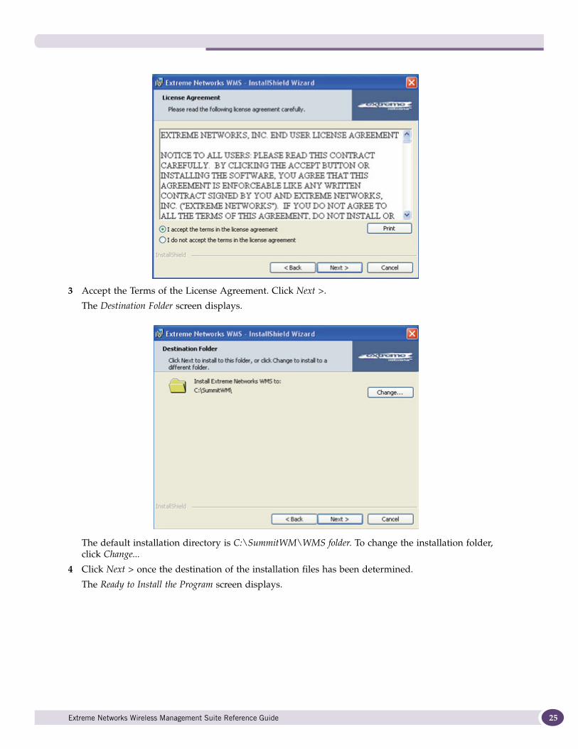
3 Accept the Terms of the License Agreement. Click Next >.
The Destination Folder screen displays.
The default installation directory is C:\SummitWM\WMS folder. To change the installation folder, click Change...
4 Click Next > once the destination of the installation files has been determined.
The Ready to Install the Program screen displays.
Extreme Networks Wireless Management Suite Reference Guide 25
Installing and Licensing WMS
26
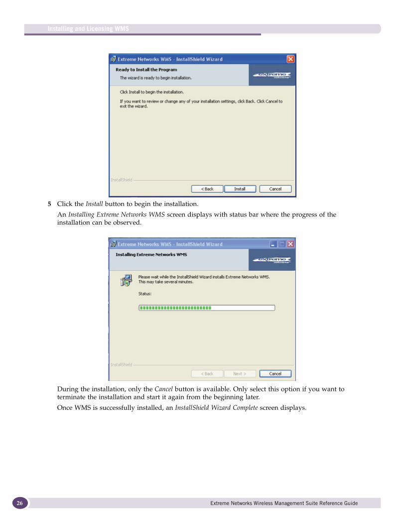
5 Click the Install button to begin the installation.
An Installing Extreme Networks WMS screen displays with status bar where the progress of the installation can be observed.
During the installation, only the Cancel button is available. Only select this option if you want to terminate the installation and start it again from the beginning later.
Once WMS is successfully installed, an InstallShield Wizard Complete screen displays.
Extreme Networks Wireless Management Suite Reference Guide
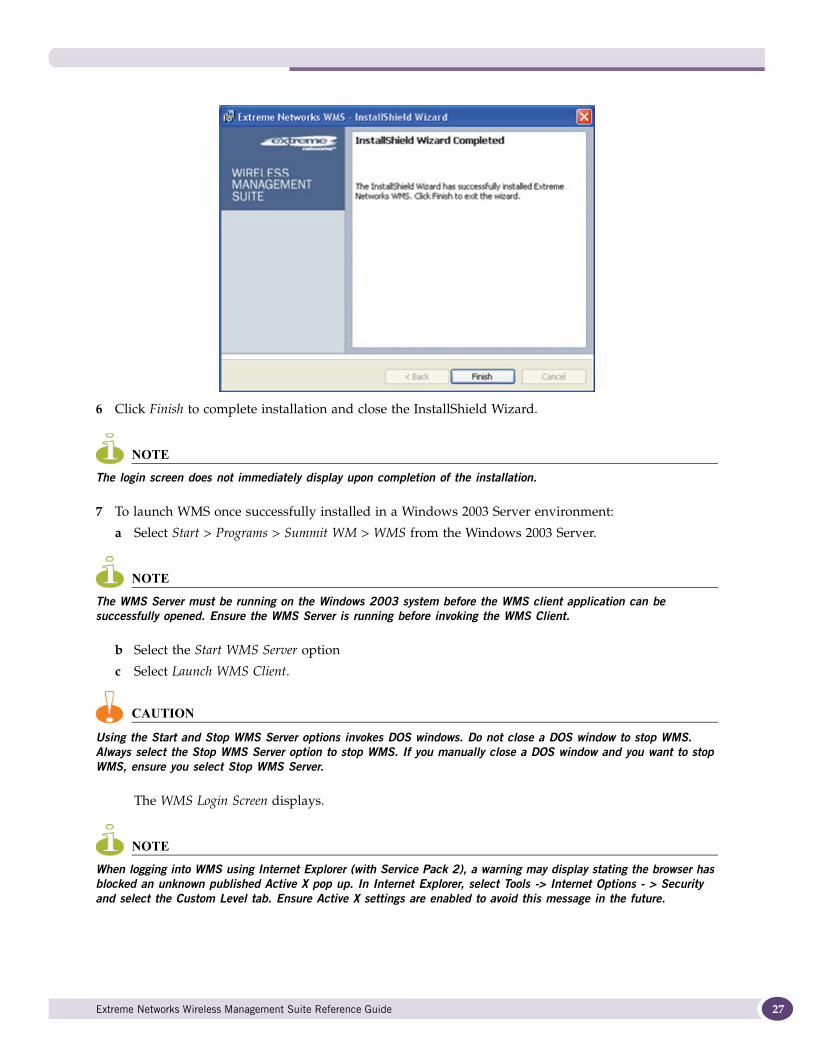
6 Click Finish to complete installation and close the InstallShield Wizard.
NOTE
The login screen does not immediately display upon completion of the installation.
7 To launch WMS once successfully installed in a Windows 2003 Server environment:
a Select Start > Programs > Summit WM > WMS from the Windows 2003 Server.
NOTE
The WMS Server must be running on the Windows 2003 system before the WMS client application can be successfully opened. Ensure the WMS Server is running before invoking the WMS Client.
b Select the Start WMS Server option
c Select Launch WMS Client.
CAUTION
Using the Start and Stop WMS Server options invokes DOS windows. Do not close a DOS window to stop WMS. Always select the Stop WMS Server option to stop WMS. If you manually close a DOS window and you want to stop WMS, ensure you select Stop WMS Server.
The WMS Login Screen displays.
NOTE
When logging into WMS using Internet Explorer (with Service Pack 2), a warning may display stating the browser has blocked an unknown published Active X pop up. In Internet Explorer, select Tools -> Internet Options - > Security and select the Custom Level tab. Ensure Active X settings are enabled to avoid this message in the future.
Extreme Networks Wireless Management Suite Reference Guide 27
Installing and Licensing WMS
28
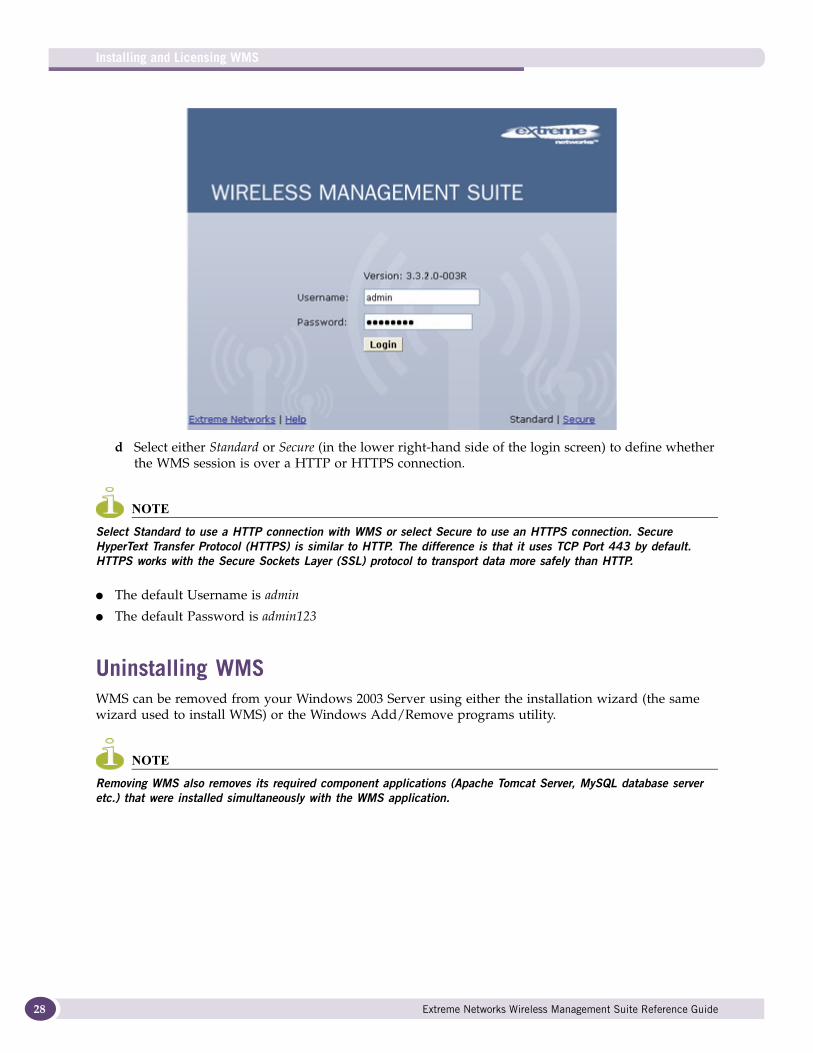
d Select either Standard or Secure (in the lower right-hand side of the login screen) to define whether the WMS session is over a HTTP or HTTPS connection.
NOTE
Select Standard to use a HTTP connection with WMS or select Secure to use an HTTPS connection. Secure HyperText Transfer Protocol (HTTPS) is similar to HTTP. The difference is that it uses TCP Port 443 by default. HTTPS works with the Secure Sockets Layer (SSL) protocol to transport data more safely than HTTP.
● The default Username is admin
● The default Password is admin123
Uninstalling WMSWMS can be removed from your Windows 2003 Server using either the installation wizard (the same wizard used to install WMS) or the Windows Add/Remove programs utility.
NOTE
Removing WMS also removes its required component applications (Apache Tomcat Server, MySQL database server etc.) that were installed simultaneously with the WMS application.
Extreme Networks Wireless Management Suite Reference Guide
To remove WMS using the installation wizard:
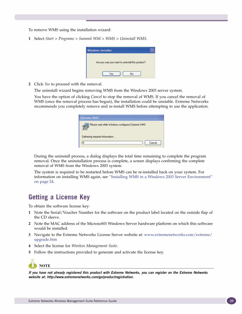
1 Select Start > Programs > Summit WM > WMS > Uninstall WMS.
2 Click Yes to proceed with the removal.
The uninstall wizard begins removing WMS from the Windows 2003 server system.
You have the option of clicking Cancel to stop the removal of WMS. If you cancel the removal of WMS (once the removal process has begun), the installation could be unstable. Extreme Networks recommends you completely remove and re-install WMS before attempting to use the application.
During the uninstall process, a dialog displays the total time remaining to complete the program removal. Once the uninstallation process is complete, a screen displays confirming the complete removal of WMS from the Windows 2003 system.
The system is required to be restarted before WMS can be re-installed back on your system. For information on installing WMS again, see “Installing WMS in a Windows 2003 Server Environment” on page 24.
Getting a License KeyTo obtain the software license key:
1 Note the Serial/Voucher Number for the software on the product label located on the outside flap of the CD sleeve.
2 Note the MAC address of the Microsoft® Windows Server hardware platform on which this software would be installed.
3 Navigate to the Extreme Networks License Server website at: www.extremenetworks.com/extreme/upgrade.htm
4 Select the license for Wireless Management Suite.
5 Follow the instructions provided to generate and activate the license key.
NOTE
If you have not already registered this product with Extreme Networks, you can register on the Extreme Networks website at: http://www.extremenetworks.com/go/productregistration.
Extreme Networks Wireless Management Suite Reference Guide 29

Installing and Licensing WMS
30
Extreme Networks Wireless Management Suite Reference Guide
4 Planning Your Network Deployment
Extreme Networks recommends any company planning to deploy a wireless network simulate their deployment plans prior to deploying the installation. Summit WMScanner provides users with powerful and industry leading site survey tools for optimizing network deployment.
Summit WMScanner enables you to design, model, and measure 802.11an and 802.11bgn networks. Building facilities and campus environments can be quickly modeled using menus that guide you step-by-step. Quickly place access points during the WLAN design phase. Once a WLAN has been deployed, use Summit WMScanner’s powerful features for measuring network performance and validating network designs.
Summit WMScanner is bundled with WMS on the product CDROM (or Website download) and is installed and licensed seamlessly with the WMS application. Summit WMScanner does not function autonomously within WMS, and has the ability to share data with WMS for those devices deployed within a Summit WMScanner maintained drawing.
To access the Summit WMScanner User Guide for detailed information on managing work spaces and creating drawings that can be used with WMS, refer to http://www.extremenetworks.com/go/documentation.
For information on installing Summit WMScanner for use with WMS, see “Installing Summit WMScanner from WMS” on page 31.
Once correctly installed, use Summit WMScanner with WMS to optimally share data between applications as specific site management activities dictate. For more information, see “Exporting Site Information from Summit WMScanner into WMS” on page 32 or “Importing WMS Data into Summit WMScanner” on page 35.
Installing Summit WMScanner from WMSWMS is shipped with Summit WMScanner. Once WMS is installed and deployed, optionally download Sit (from within WMS), extract the installation package, install Summit WMScanner and begin porting site information between WMS and Summit WMScanner.
Once you have successfully installed Summit WMScanner, refer to “Exporting Site Information from Summit WMScanner into WMS” on page 32 to begin moving information back and forth between the WMS and Summit WMScanner applications.
NOTE
When Summit WMScanner is installed from WMS, you can use Summit WMScanner for 14 days with a trial license. For more information see “Getting a License Key” on page 29.
To install Summit WMScanner for the first time from WMS:
1 Login to WMS with the credentials of an administrative user.
2 Refer to the My Network menu in the upper left-hand side of the WMS console and select a site.
Extreme Networks Wireless Management Suite Reference Guide 31
Planning Your Network Deployment
32
If no sites have been created thus far, WMS still displays a NOC (default) site that can be used to install Summit WMScanner.
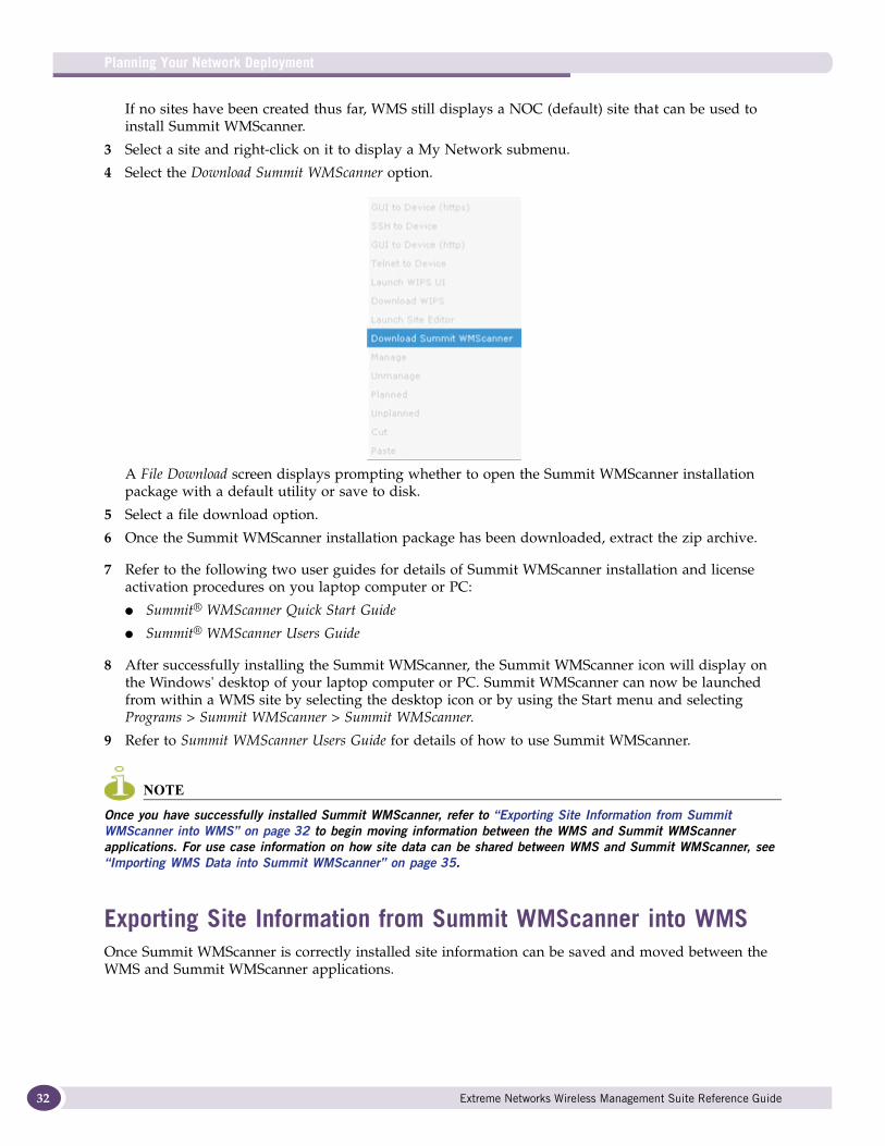
3 Select a site and right-click on it to display a My Network submenu.
4 Select the Download Summit WMScanner option.
A File Download screen displays prompting whether to open the Summit WMScanner installation package with a default utility or save to disk.
5 Select a file download option.
6 Once the Summit WMScanner installation package has been downloaded, extract the zip archive.
7 Refer to the following two user guides for details of Summit WMScanner installation and license activation procedures on you laptop computer or PC:
● Summit® WMScanner Quick Start Guide
● Summit® WMScanner Users Guide
8 After successfully installing the Summit WMScanner, the Summit WMScanner icon will display on the Windows' desktop of your laptop computer or PC. Summit WMScanner can now be launched from within a WMS site by selecting the desktop icon or by using the Start menu and selecting Programs > Summit WMScanner > Summit WMScanner.
9 Refer to Summit WMScanner Users Guide for details of how to use Summit WMScanner.
NOTE
Once you have successfully installed Summit WMScanner, refer to “Exporting Site Information from Summit WMScanner into WMS” on page 32 to begin moving information between the WMS and Summit WMScanner applications. For use case information on how site data can be shared between WMS and Summit WMScanner, see “Importing WMS Data into Summit WMScanner” on page 35.
Exporting Site Information from Summit WMScanner into WMSOnce Summit WMScanner is correctly installed site information can be saved and moved between the WMS and Summit WMScanner applications.
Extreme Networks Wireless Management Suite Reference Guide
CAUTION
Summit WMScanner drawings exported to WMS can use a maximum of 8 unique partition types. If duplicate partition types are used in the same Summit WMScanner design, some wall information will be discarded when the design is exported to WMS. In WMS, walls will be missing from floor plan displays and heat maps will not properly record the presence of the obstructions.
To export information between Summit WMScanner and WMS:
1 Launch Summit WMScanner from within a WMS site, by selecting the desktop icon or by using the Start menu and selecting Programs > Summit WMScanner > Summit WMScanner.
No login or password requirement exists.
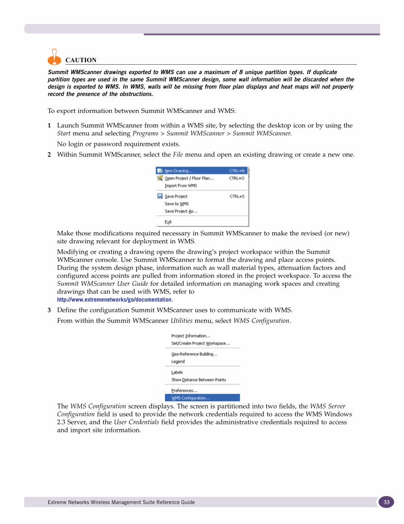
2 Within Summit WMScanner, select the File menu and open an existing drawing or create a new one.
Make those modifications required necessary in Summit WMScanner to make the revised (or new) site drawing relevant for deployment in WMS.
Modifying or creating a drawing opens the drawing’s project workspace within the Summit WMScanner console. Use Summit WMScanner to format the drawing and place access points. During the system design phase, information such as wall material types, attenuation factors and configured access points are pulled from information stored in the project workspace. To access the Summit WMScanner User Guide for detailed information on managing work spaces and creating drawings that can be used with WMS, refer to http://www.extremenetworks/go/documentation.
3 Define the configuration Summit WMScanner uses to communicate with WMS.
From within the Summit WMScanner Utilities menu, select WMS Configuration.
The WMS Configuration screen displays. The screen is partitioned into two fields, the WMS Server Configuration field is used to provide the network credentials required to access the WMS Windows 2.3 Server, and the User Credentials field provides the administrative credentials required to access and import site information.
Extreme Networks Wireless Management Suite Reference Guide 33
Planning Your Network Deployment
34
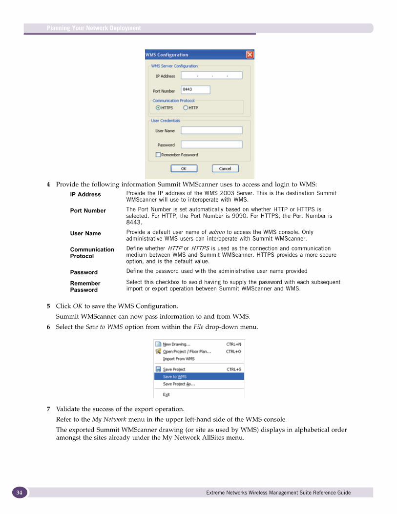
4 Provide the following information Summit WMScanner uses to access and login to WMS:
5 Click OK to save the WMS Configuration.
Summit WMScanner can now pass information to and from WMS.
6 Select the Save to WMS option from within the File drop-down menu.
7 Validate the success of the export operation.
Refer to the My Network menu in the upper left-hand side of the WMS console.
The exported Summit WMScanner drawing (or site as used by WMS) displays in alphabetical order amongst the sites already under the My Network AllSites menu.
IP Address Provide the IP address of the WMS 2003 Server. This is the destination Summit WMScanner will use to interoperate with WMS.
Port Number The Port Number is set automatically based on whether HTTP or HTTPS is selected. For HTTP, the Port Number is 9090. For HTTPS, the Port Number is 8443.
User Name Provide a default user name of admin to access the WMS console. Only administrative WMS users can interoperate with Summit WMScanner.
Communication Protocol
Define whether HTTP or HTTPS is used as the connection and communication medium between WMS and Summit WMScanner. HTTPS provides a more secure option, and is the default value.
Password Define the password used with the administrative user name provided
Remember Password
Select this checkbox to avoid having to supply the password with each subsequent import or export operation between Summit WMScanner and WMS.
Extreme Networks Wireless Management Suite Reference Guide
Importing WMS Data into Summit WMScannerUse Summit WMScanner to import WMS site information into the Summit WMScanner application. Once imported, information can be shared between both applications as specific configuration activities dictate the use of one of the two applications.
To import WMS site information into Summit WMScanner:
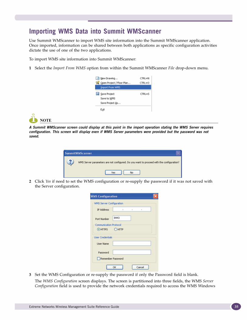
1 Select the Import From WMS option from within the Summit WMScanner File drop-down menu.
NOTE
A Summit WMScanner screen could display at this point in the import operation stating the WMS Server requires configuration. This screen will display even if WMS Server parameters were provided but the password was not saved.
2 Click Yes if need to set the WMS configuration or re-supply the password if it was not saved with the Server configuration.
3 Set the WMS Configuration or re-supply the password if only the Password field is blank.
The WMS Configuration screen displays. The screen is partitioned into three fields, the WMS Server Configuration field is used to provide the network credentials required to access the WMS Windows
Extreme Networks Wireless Management Suite Reference Guide 35

Planning Your Network Deployment
36
2003 Server, and the User Credentials field provides the administrative credentials required to access and import site information.
4 Click OK to save the configuration.
At this point in the Import operation, select a Design (as referred to in Summit WMScanner) to choose the WMS site to be imported into Summit WMScanner. The Select a Design To Download From WMS screen contains sites created in WMS that can be imported. Once imported, consider generating an RF heat map to discern areas of good coverage versus bad within this site. A heat map is a visualization based map of the site’s floor plan representative of the actual dimensions of the site’s coverage area.
5 Select an existing WMS site and click OK to begin the import operation into Summit WMScanner.
Upon the successful import of the site, a “design downloaded successfully” screen displays. Click OK to conclude the import operation.
IP Address Provide the IP address of the WMS 2003 Server. This is the destination Summit WMScanner will use to interoperate with WMS.
Port Number The Port Number is set automatically based on whether HTTP or HTTPS is selected. For HTTP, the Port Number is 9090. For HTTPS, the Port Number is 8443.
User Name Provide a default user name of admin to access the WMS console. Only administrative WMS users can interoperate with Summit WMScanner.
Communication Protocol
Define whether HTTP or HTTPS is used as the connection and communication medium between WMS and Summit WMScanner. HTTPS provides a more secure option, and is the default value.
Password Define the password used with the administrative user name provided
Remember Password
Select this checkbox to avoid having to supply the password with each subsequent import or export operation between Summit WMScanner and WMS.
Extreme Networks Wireless Management Suite Reference Guide
5 My Network Configuration
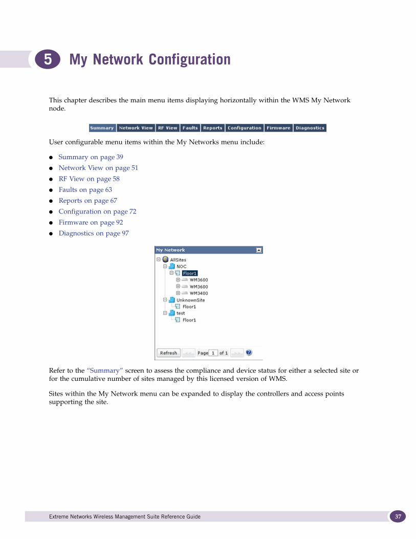
This chapter describes the main menu items displaying horizontally within the WMS My Network node.
User configurable menu items within the My Networks menu include:
● Summary on page 39
● Network View on page 51
● RF View on page 58
● Faults on page 63
● Reports on page 67
● Configuration on page 72
● Firmware on page 92
● Diagnostics on page 97
Refer to the “Summary” screen to assess the compliance and device status for either a selected site or for the cumulative number of sites managed by this licensed version of WMS.
Sites within the My Network menu can be expanded to display the controllers and access points supporting the site.
Extreme Networks Wireless Management Suite Reference Guide 37
My Network Configuration
38
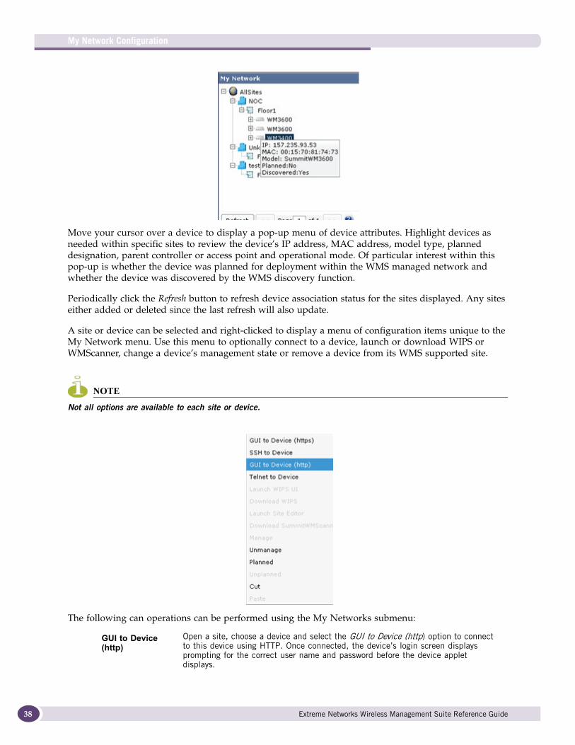
Move your cursor over a device to display a pop-up menu of device attributes. Highlight devices as needed within specific sites to review the device’s IP address, MAC address, model type, planned designation, parent controller or access point and operational mode. Of particular interest within this pop-up is whether the device was planned for deployment within the WMS managed network and whether the device was discovered by the WMS discovery function.
Periodically click the Refresh button to refresh device association status for the sites displayed. Any sites either added or deleted since the last refresh will also update.
A site or device can be selected and right-clicked to display a menu of configuration items unique to the My Network menu. Use this menu to optionally connect to a device, launch or download WIPS or WMScanner, change a device’s management state or remove a device from its WMS supported site.
NOTE
Not all options are available to each site or device.
The following can operations can be performed using the My Networks submenu:
GUI to Device (http)
Open a site, choose a device and select the GUI to Device (http) option to connect to this device using HTTP. Once connected, the device’s login screen displays prompting for the correct user name and password before the device applet displays.
Extreme Networks Wireless Management Suite Reference Guide
SummaryDisplay the Summary screen to review device and network address information for devices detected within the selected site. Use this information to review the status of detected devices and their physical location.
A Dashboard function is one of the Summary screen sub functions. The Dashboard is a significant enhancement to the WMS Summary functionality, allowing administrators to make global (all sites), site specific and device specific inquiries into the performance, network addressing and device health of all the components within a licensed WMS deployment. For more information, refer to “Dashboard” on page 40.
A WMS deployment is supported by sites comprised of controllers and access points whose network address, status and compliance information can be listed within the DeviceList.
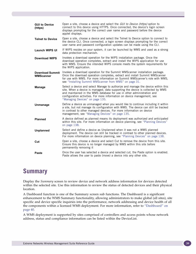
GUI to Device (https)
Open a site, choose a device and select the GUI to Device (https) option to connect to this device using HTTPS. Once connected, the device’s login screen displays prompting for the correct user name and password before the device applet displays.
Telnet to Device Open a site, choose a device and select the Telnet to Device option to connect to the device CLI. Once connected, a login screen displays prompting for the correct user name and password configuration updates can be made using the CLI.
Launch WIPS UI If WIPS resides on your system, it can be launched by WMS and used as a strong data protection mechanism.
Download WIPS Invokes a download operation for the WIPS installation package. Once the download operation completes, extract and install the WIPS application for use with WMS. Ensure the intended WIPS console meets the system requirements for the WIPS application.
Download Summit WMScanner
Invokes a download operation for the Summit WMScanner installation package. Once the download operation completes, extract and install Summit WMScanner for use with WMS. For more information on Summit WMScanner’s role with WMS, see “Installing Summit WMScanner from WMS” on page 31.
Manage Select a device and select Manage to authorize and manage the device within this site. When a device is managed, data supporting the device is collected by WMS and maintained in the WMS database for use in other administration and configuration activities. For more information on device management, see “Managing Devices” on page 135.
Unmanage Define a device as unmanaged when you would like to continue including it within a site, but not manage its configuration with WMS. The device can still be tracked in contrast to other managed devices. For more information on device management, see “Managing Devices” on page 135.
Planned A device defined as planned means its deployment was authorized and anticipated within this site. For more information on device planning, see “Planning Devices” on page 138.
Unplanned Select and define a device as Unplanned when it was not a WMS planned deployment. The device can still be tracked in contrast to other planned devices. For more information on device planning, see “Planning Devices” on page 138.
Cut Open a site, choose a device and select Cut to remove the device from this site. Ensure this device is no longer managed by WMS within this site before permanently removing it
Paste Once the user has selected a device and selected cut, the Paste option is enabled. Paste allows the user to paste (move) a device into any other site.
Extreme Networks Wireless Management Suite Reference Guide 39
My Network Configuration
40
A controller or access point device link can be selected within the DeviceList to launch a device specific Dashboard to help determine whether the controller or access point ‘s current load on the network. For more information, see “DeviceList” on page 49.
DashboardThe following dashboards can be accessed from the summary screen to display Dashboard information for all the sites supported by WMS collectively, an individual site or an individual device within a specific site:
● AllSites Dashboard on page 40
● Site Specific Dashboard on page 43
● Device Specific Dashboards on page 45
● MU Clients on page 46
● WLANs on page 47
● Radios on page 48
● DeviceList on page 49
● Radios on page 50
The content of the all sites and site specific Dashboards are similar, the central difference being the all sites Dashboard has a much larger pool of information to draw from when multiple sites and devices are deployed. Both the all sites and site specific Dashboards display throughput data for the top five radio and clients.
A device specific Dashboard displays and describes information far more granular and device specific than either the all site of specific site dashboards. Device specific Dashboards define specific device performance and network address information independent from the device’s site and floor deployment. When a specific device is selected from the My Network main menu, additional MU Clients, WLANs and Radios tabs could display (depending on the device used in the Dashboard) and are available for listing the attributes of the clients connected to the device and to the attributes of the WLANs available for device connection.
AllSites DashboardWMS can display a Dashboard with data polled from each site, floor and device supported in this licensed version. An all sites Dashboard is a useful single point of reference for performance and event information for an entire WMS managed deployment.
To display a Dashboard for all the sites currently supported by this version of WMS:
1 Select the My Network main menu item.
2 Select the AllSites node.
3 Select Summary tab (if not already displayed).
4 Select the Dashboard tab.
Extreme Networks Wireless Management Suite Reference Guide

5 Refer to the following all site data appearing within the Dashboard’s top main display field.
Scroll down the All Sites dashboard as necessary to display information.
6 Refer to the bottom of the half of the Dashboard to review the top five radios and clients reporting maximum throughout.
Device Status Displays device event information in pie-chart format for all the sites supported by this licensed version of WMS.
Configuration Compliance
Displays compliance information for all sites. Compliance is achieved by detecting configuration changes and alerting WMS about changes from the last saved configuration. A controller has two types of default configurations: a Saved Config and Running Config. The Saved Config resides in a controller persistent file within the controller’s file system.The controller runs with the Saved Config after a restart. The Running Config resides in controller memory. The Running Config is equal to the Saved Config just after a restart. Any changes made to the Running Config are lost in the event of a controller restart (if changes are not saved). For more information on configuring the mechanisms used to assess compliance, see “Compliance” on page 73.
Planned Vs Discovered
Displays a ratio of the number of devices planned versus the number actually deployed and discovered for all the sites supported by this licensed version of WMS. For information, see “Device Management” on page 134.
Devices Per Model
Displays a ratio of the different device models detected out of the total deployed. for all the sites supported by this licensed version of WMS.
Radio Channel Displays a radio channel utilization report (in pie chart format) for all the sites supported by this version of WMS. Select a channel to the right of the pie chart to assess how that channel in being utilized in respect to the other channels supported.
Radio Retries/Throughput
Displays a ratio of radio retries versus radio throughput for all the sites managed by this licensed version of WMS.
Radio Report Displays the number of 802.11a (yellow), 802.11b/g/n (light blue), 802.11a/n (dark blue) and 802.11b/g (purple) radios proliferating the supported WMS sites.
MU Report Lists the number of MUs associated to WMS managed radio devices and the radio band they are supporting. This data is displayed over an hourly timeline for all the sites supported by this licensed version of WMS.
Extreme Networks Wireless Management Suite Reference Guide 41
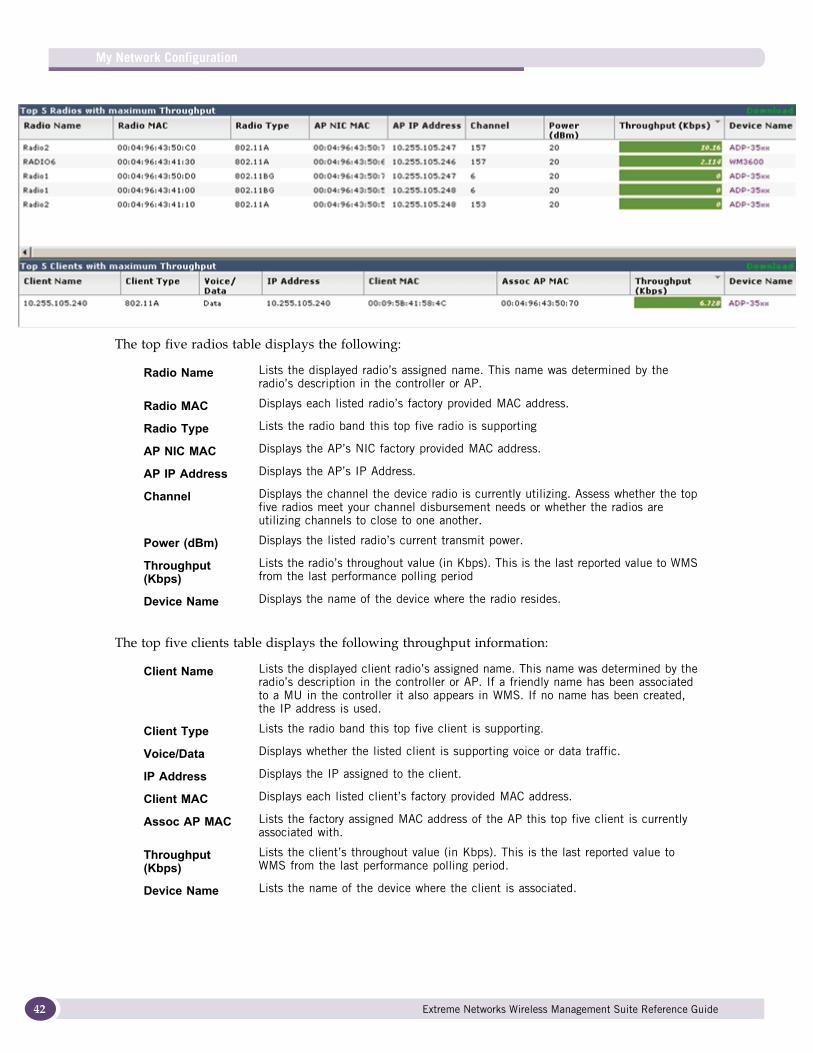
My Network Configuration
42
The top five radios table displays the following:
The top five clients table displays the following throughput information:
Radio Name Lists the displayed radio’s assigned name. This name was determined by the radio’s description in the controller or AP.
Radio MAC Displays each listed radio’s factory provided MAC address.
Radio Type Lists the radio band this top five radio is supporting
AP NIC MAC Displays the AP’s NIC factory provided MAC address.
AP IP Address Displays the AP’s IP Address.
Channel Displays the channel the device radio is currently utilizing. Assess whether the top five radios meet your channel disbursement needs or whether the radios are utilizing channels to close to one another.
Power (dBm) Displays the listed radio’s current transmit power.
Throughput (Kbps)
Lists the radio’s throughout value (in Kbps). This is the last reported value to WMS from the last performance polling period
Device Name Displays the name of the device where the radio resides.
Client Name Lists the displayed client radio’s assigned name. This name was determined by the radio’s description in the controller or AP. If a friendly name has been associated to a MU in the controller it also appears in WMS. If no name has been created, the IP address is used.
Client Type Lists the radio band this top five client is supporting.
Voice/Data Displays whether the listed client is supporting voice or data traffic.
IP Address Displays the IP assigned to the client.
Client MAC Displays each listed client’s factory provided MAC address.
Assoc AP MAC Lists the factory assigned MAC address of the AP this top five client is currently associated with.
Throughput(Kbps)
Lists the client’s throughout value (in Kbps). This is the last reported value to WMS from the last performance polling period.
Device Name Lists the name of the device where the client is associated.
Extreme Networks Wireless Management Suite Reference Guide
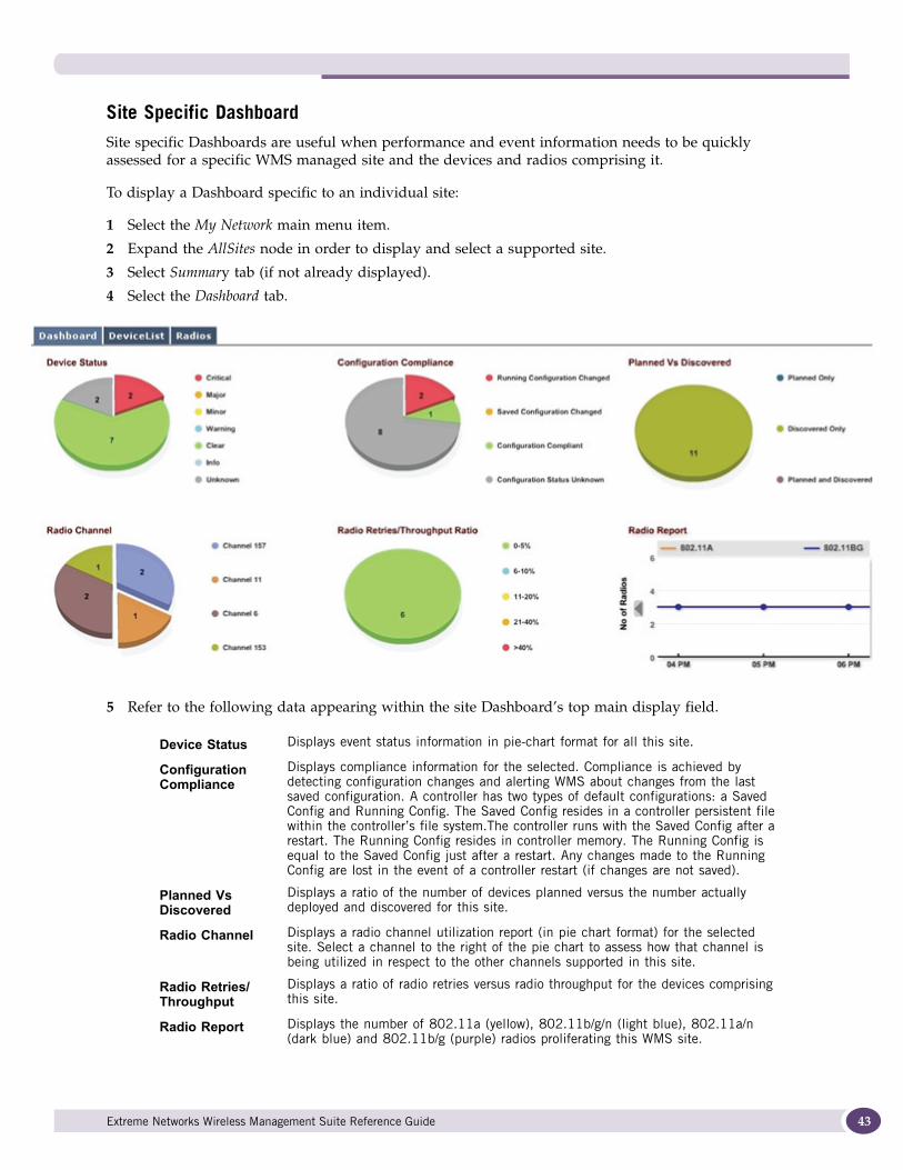
Site Specific DashboardSite specific Dashboards are useful when performance and event information needs to be quickly assessed for a specific WMS managed site and the devices and radios comprising it.
To display a Dashboard specific to an individual site:
1 Select the My Network main menu item.
2 Expand the AllSites node in order to display and select a supported site.
3 Select Summary tab (if not already displayed).
4 Select the Dashboard tab.
5 Refer to the following data appearing within the site Dashboard’s top main display field.
Device Status Displays event status information in pie-chart format for all this site.
Configuration Compliance
Displays compliance information for the selected. Compliance is achieved by detecting configuration changes and alerting WMS about changes from the last saved configuration. A controller has two types of default configurations: a Saved Config and Running Config. The Saved Config resides in a controller persistent file within the controller’s file system.The controller runs with the Saved Config after a restart. The Running Config resides in controller memory. The Running Config is equal to the Saved Config just after a restart. Any changes made to the Running Config are lost in the event of a controller restart (if changes are not saved).
Planned Vs Discovered
Displays a ratio of the number of devices planned versus the number actually deployed and discovered for this site.
Radio Channel Displays a radio channel utilization report (in pie chart format) for the selected site. Select a channel to the right of the pie chart to assess how that channel is being utilized in respect to the other channels supported in this site.
Radio Retries/Throughput
Displays a ratio of radio retries versus radio throughput for the devices comprising this site.
Radio Report Displays the number of 802.11a (yellow), 802.11b/g/n (light blue), 802.11a/n (dark blue) and 802.11b/g (purple) radios proliferating this WMS site.
Extreme Networks Wireless Management Suite Reference Guide 43
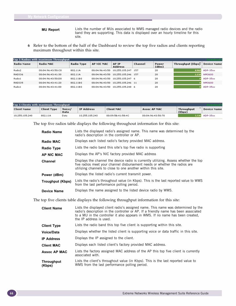
My Network Configuration
44
6 Refer to the bottom of the half of the Dashboard to review the top five radios and clients reporting maximum throughout within this site.
The top five radios table displays the following throughout information for this site:
The top five clients table displays the following throughput information for this site:
MU Report Lists the number of MUs associated to WMS managed radio devices and the radio band they are supporting. This data is displayed over an hourly timeline for this site.
Radio Name Lists the displayed radio’s assigned name. This name was determined by the radio’s description in the controller or AP.
Radio MAC Displays each listed radio’s factory provided MAC address.
Radio Type Lists the radio band this site’s top five radio is supporting
AP NIC MAC Displays the AP’s NIC factory provided MAC address
Channel Displays the channel the device radio is currently utilizing. Assess whether the top five radios meet your channel disbursement needs or whether the radios are utilizing channels to close to one another within this site.
Power (dBm) Displays the listed radio’s current transmit power.
Troughput (Kbps) Lists the radio’s throughout value (in Kbps). This is the last reported value to WMS from the last performance polling period.
Device Name Displays the name assigned to the listed device radio by WMS.
Client Name Lists the displayed client radio’s assigned name. This name was determined by the radio’s description in the controller or AP. If a friendly name has been associated to a MU in the controller it also appears in WMS. If no name has been created, the IP address is used.
Client Type Lists the radio band this top five client is supporting within this site.
Voice/Data Displays whether the listed client is supporting voice or data traffic in this site.
IP Address Displays the IP assigned to the client.
Client MAC Displays each listed client’s factory provided MAC address.
Assoc AP MAC Lists the factory assigned MAC address of the AP this top five client is currently associated with.
Throughput (Kbps)
Lists the client’s throughout value (in Kbps). This is the last reported value to WMS from the last performance polling period.
Extreme Networks Wireless Management Suite Reference Guide
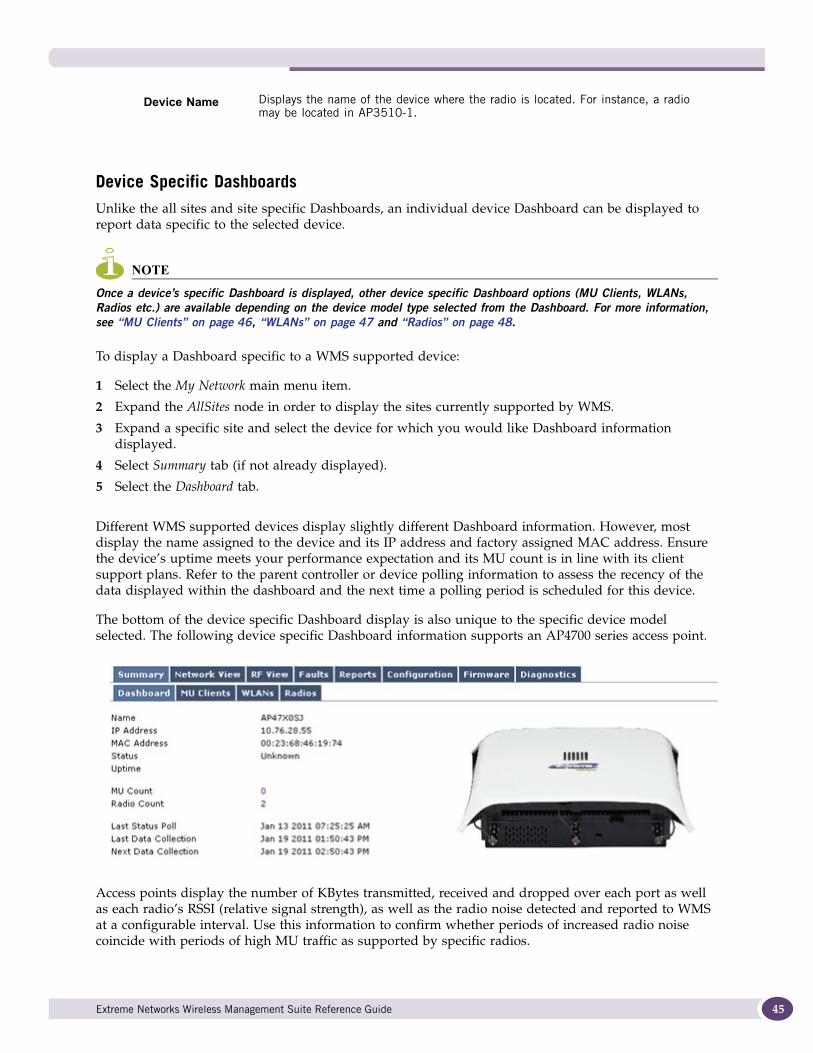
Device Specific DashboardsUnlike the all sites and site specific Dashboards, an individual device Dashboard can be displayed to report data specific to the selected device.
NOTE
Once a device’s specific Dashboard is displayed, other device specific Dashboard options (MU Clients, WLANs, Radios etc.) are available depending on the device model type selected from the Dashboard. For more information, see “MU Clients” on page 46, “WLANs” on page 47 and “Radios” on page 48.
To display a Dashboard specific to a WMS supported device:
1 Select the My Network main menu item.
2 Expand the AllSites node in order to display the sites currently supported by WMS.
3 Expand a specific site and select the device for which you would like Dashboard information displayed.
4 Select Summary tab (if not already displayed).
5 Select the Dashboard tab.
Different WMS supported devices display slightly different Dashboard information. However, most display the name assigned to the device and its IP address and factory assigned MAC address. Ensure the device’s uptime meets your performance expectation and its MU count is in line with its client support plans. Refer to the parent controller or device polling information to assess the recency of the data displayed within the dashboard and the next time a polling period is scheduled for this device.
The bottom of the device specific Dashboard display is also unique to the specific device model selected. The following device specific Dashboard information supports an AP4700 series access point.
Access points display the number of KBytes transmitted, received and dropped over each port as well as each radio’s RSSI (relative signal strength), as well as the radio noise detected and reported to WMS at a configurable interval. Use this information to confirm whether periods of increased radio noise coincide with periods of high MU traffic as supported by specific radios.
Device Name Displays the name of the device where the radio is located. For instance, a radio may be located in AP3510-1.
Extreme Networks Wireless Management Suite Reference Guide 45
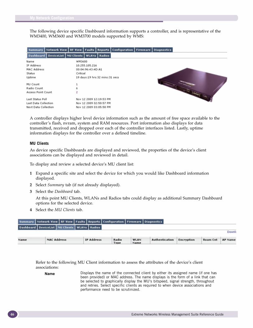
My Network Configuration
46
The following device specific Dashboard information supports a controller, and is representative of the WM3400, WM3600 and WM3700 models supported by WMS:
A controller displays higher level device information such as the amount of free space available to the controller’s flash, nvram, system and RAM resources. Port information also displays for data transmitted, received and dropped over each of the controller interfaces listed. Lastly, uptime information displays for the controller over a defined timeline.
MU Clients
As device specific Dashboards are displayed and reviewed, the properties of the device’s client associations can be displayed and reviewed in detail.
To display and review a selected device’s MU client list:
1 Expand a specific site and select the device for which you would like Dashboard information displayed.
2 Select Summary tab (if not already displayed).
3 Select the Dashboard tab.
At this point MU Clients, WLANs and Radios tabs could display as additional Summary Dashboard options for the selected device.
4 Select the MU Clients tab.
Refer to the following MU Client information to assess the attributes of the device’s client associations:
Name Displays the name of the connected client by either its assigned name (if one has been provided) or MAC address. The name displays is the form of a link that can be selected to graphically display the MU’s bitspeed, signal strength, throughout and retries. Select specific clients as required to when device associations and performance need to be scrutinized.
Extreme Networks Wireless Management Suite Reference Guide
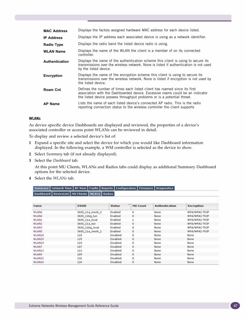
WLANs
As device specific device Dashboards are displayed and reviewed, the properties of a device’s associated controller or access point WLANs can be reviewed in detail.
To display and review a selected device’s list of:
1 Expand a specific site and select the device for which you would like Dashboard information displayed. In the following example, a WM controller is selected as the device to show.
2 Select Summary tab (if not already displayed).
3 Select the Dashboard tab.
At this point MU Clients, WLANs and Radios tabs could display as additional Summary Dashboard options for the selected device.
4 Select the WLANs tab.
MAC Address Displays the factory assigned hardware MAC address for each device listed.
IP Address Displays the IP address each associated device is using as a network identifier.
Radio Type Displays the radio band the listed device radio is using.
WLAN Name Displays the name of the WLAN the client is a member of on its connected controller.
Authentication Displays the name of the authentication scheme this client is using to secure its transmissions over the wireless network. None is listed if authentication is not used by the listed device.
Encryption Displays the name of the encryption scheme this client is using to secure its transmissions over the wireless network. None is listed if encryption is not used by the listed device.
Roam Cnt Defines the number of times each listed client has roamed since its first association with the Dashboarded device. Excessive roams could be an indicator the listed device possess throughput problems or is a potential threat.
AP Name Lists the name of each listed device’s connected AP radio. This is the radio reporting connection status to the wireless controller the client supports
Extreme Networks Wireless Management Suite Reference Guide 47
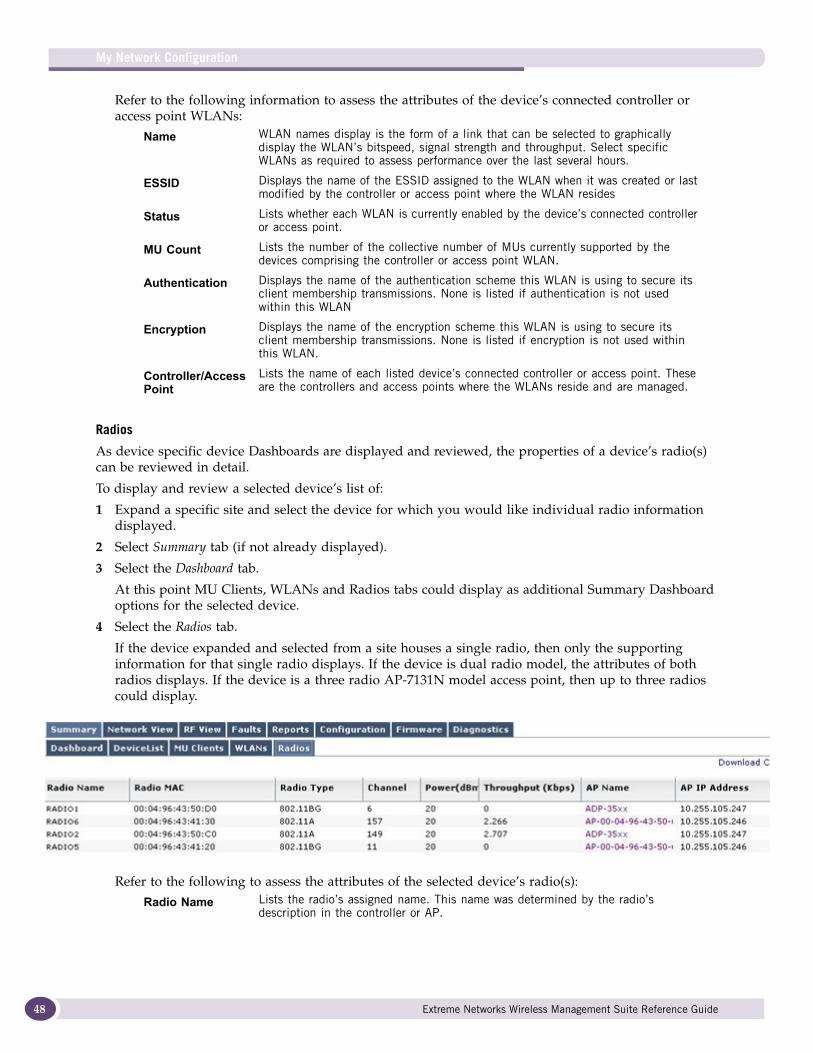
My Network Configuration
48
Refer to the following information to assess the attributes of the device’s connected controller or access point WLANs:
Radios
As device specific device Dashboards are displayed and reviewed, the properties of a device’s radio(s) can be reviewed in detail.
To display and review a selected device’s list of:
1 Expand a specific site and select the device for which you would like individual radio information displayed.
2 Select Summary tab (if not already displayed).
3 Select the Dashboard tab.
At this point MU Clients, WLANs and Radios tabs could display as additional Summary Dashboard options for the selected device.
4 Select the Radios tab.
If the device expanded and selected from a site houses a single radio, then only the supporting information for that single radio displays. If the device is dual radio model, the attributes of both radios displays. If the device is a three radio AP-7131N model access point, then up to three radios could display.
Refer to the following to assess the attributes of the selected device’s radio(s):
Name WLAN names display is the form of a link that can be selected to graphically display the WLAN’s bitspeed, signal strength and throughput. Select specific WLANs as required to assess performance over the last several hours.
ESSID Displays the name of the ESSID assigned to the WLAN when it was created or last modified by the controller or access point where the WLAN resides
Status Lists whether each WLAN is currently enabled by the device’s connected controller or access point.
MU Count Lists the number of the collective number of MUs currently supported by the devices comprising the controller or access point WLAN.
Authentication Displays the name of the authentication scheme this WLAN is using to secure its client membership transmissions. None is listed if authentication is not used within this WLAN
Encryption Displays the name of the encryption scheme this WLAN is using to secure its client membership transmissions. None is listed if encryption is not used within this WLAN.
Controller/Access Point
Lists the name of each listed device’s connected controller or access point. These are the controllers and access points where the WLANs reside and are managed.
Radio Name Lists the radio’s assigned name. This name was determined by the radio’s description in the controller or AP.
Extreme Networks Wireless Management Suite Reference Guide
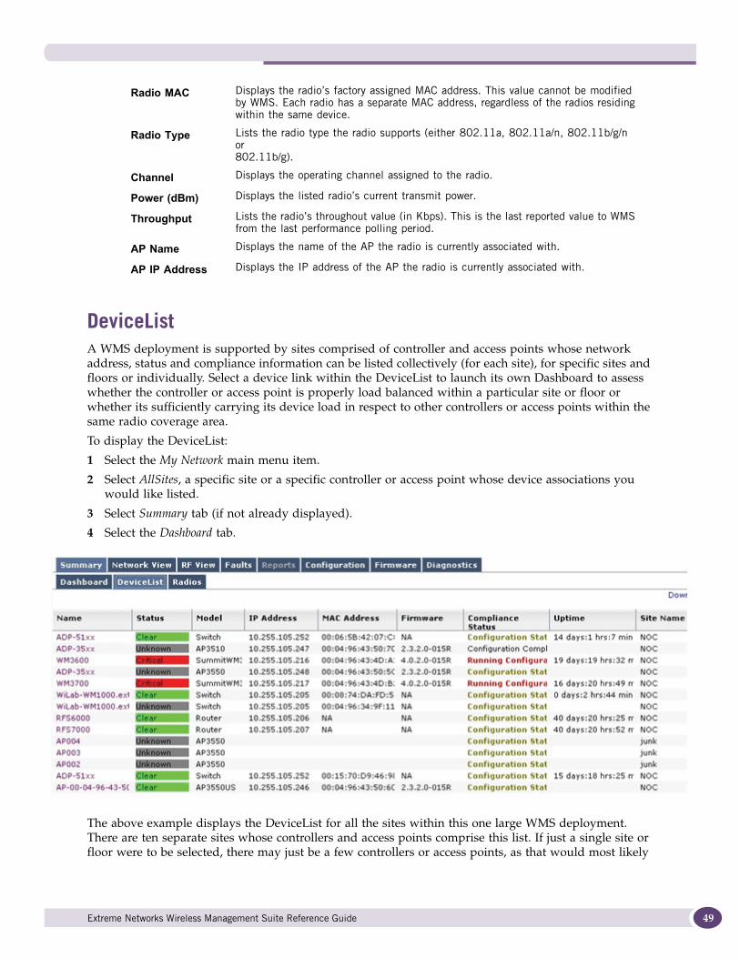
DeviceListA WMS deployment is supported by sites comprised of controller and access points whose network address, status and compliance information can be listed collectively (for each site), for specific sites and floors or individually. Select a device link within the DeviceList to launch its own Dashboard to assess whether the controller or access point is properly load balanced within a particular site or floor or whether its sufficiently carrying its device load in respect to other controllers or access points within the same radio coverage area.
To display the DeviceList:
1 Select the My Network main menu item.
2 Select AllSites, a specific site or a specific controller or access point whose device associations you would like listed.
3 Select Summary tab (if not already displayed).
4 Select the Dashboard tab.
The above example displays the DeviceList for all the sites within this one large WMS deployment. There are ten separate sites whose controllers and access points comprise this list. If just a single site or floor were to be selected, there may just be a few controllers or access points, as that would most likely
Radio MAC Displays the radio’s factory assigned MAC address. This value cannot be modified by WMS. Each radio has a separate MAC address, regardless of the radios residing within the same device.
Radio Type Lists the radio type the radio supports (either 802.11a, 802.11a/n, 802.11b/g/n or 802.11b/g).
Channel Displays the operating channel assigned to the radio.
Power (dBm) Displays the listed radio’s current transmit power.
Throughput Lists the radio’s throughout value (in Kbps). This is the last reported value to WMS from the last performance polling period.
AP Name Displays the name of the AP the radio is currently associated with.
AP IP Address Displays the IP address of the AP the radio is currently associated with.
Extreme Networks Wireless Management Suite Reference Guide 49
My Network Configuration
50
be sufficient to service the client needs of just that single site or floor. If a single device were to be selected, just the attributes of that one device would display within the DeviceList.
The following displays within the DeviceList regardless of whether all sites, a single site or floor or just an individual device is selected:
RadiosA WMS deployment is supported by sites comprised of controllers, access points and their associated device radios whose hardcoded MAC address, assigned name, radio type, channel, power, throughput and associated AP information can be listed collectively (for all sites), for specific sites (and floors) or individual device associations.
Name Lists the names of the controller or access points detected. Each name displays in the form of a link that can be selected to graphically display the controller or access point’s device specific Dashboard. For more information on device specific dashboards, see “Device Specific Dashboards” on page 45.
Status Assess the controller’s or access point’s current operational status based on the following indicators:
Critical - Red
Major - Orange
Minor - Yellow
Warning - Blue
Clear - Green
Info - White
Model Lists the model of each controller or access point. Different controller and access point models have different client support capabilities, so it helps to know the listed device’s support capabilities in respect to the number of clients it is supporting.
IP Address Displays the IP address each listed controller or access point is using as a network identifier.
MAC Address Displays the factory assigned hardware MAC address for each controller and access point listed.
Firmware Displays the version of controller or access point firmware currently running on the listed device. Extreme Networks frequently releases updated versions of device firmware to its support Web site, so knowing which firmware is on its listed controller or access point can help determine whether a firmware update is warranted. For more information on firmware updates, see “Firmware” on page 92.
Compliance Status
Displays compliance information for the controller or access point. A controller has two types of default configurations: a Saved Config and Running Config. The Saved Config resides in a controller persistent file within the controller’s file system.The controller runs with the Saved Config after a restart. The Running Config resides in controller memory. The Running Config is equal to the Saved Config just after a restart. Any changes made to the Running Config are lost in the event of a controller restart (if changes are not saved). For more information on configuring the mechanisms used to asses compliance, see “Compliance” on page 73.
Uptime Lists the time (in days, hours and minutes) the controller or access point has been operational.
Site Name Displays the name of the site wherein this controller or access point resides. Assess whether the number of devices listed for each site seems appropriate to the clients needs of the site.
Extreme Networks Wireless Management Suite Reference Guide
This information can help determine whether a site is properly load balanced is respect to the coverage needs of the clients within, as well as whether the radio’s channel and band is best suited to a site or floor’s radio traffic requirements.
To display AllSite radio information:
1 Select the My Network main menu item.
2 Select AllSites, a specific site or a specific controller or access point whose device associations you would like listed.
3 Select the Summary tab (if not already displayed).
4 Select the Radios tab.
Refer to the following information to assess the attributes of each listed radio:
Network ViewNetwork View provides a visual representation of the network infrastructure devices, mobile devices and logical connections between devices. Network View includes a search function for finding network and mobile devices and obtaining status for each device in a WMS supported wireless network.
A Network View map is automatically generated by WMS based on the devices found in the Network Discovery process. For information on conducting a Network Discovery to help populate the Network View, see “Network Discovery” on page 142.
When Network View is selected from the My Network main menu item, the WMS display is populated with the following Network View menu bar options:
Radio Name Lists the displayed radio’s assigned name. This name was determined by the radio’s description in the controller or AP.
Radio MAC Displays each listed radio’s factory assigned MAC address. This value cannot be modified by WMS.
Radio Type Lists the radio type each listed radio supports (either 802.11a, 802.11a/n, 802.11b/g/n or 802.11b/g).
Channel Displays the channel the radio is currently utilizing. Assess whether the listed radios meet your channel disbursement needs or whether the radios are utilizing channels to close to one another.
Power (dBm) Displays the listed radio’s current transmit power.
Throughput Lists the radio’s throughout value (in Kbps). This is the last reported value to WMS from the last performance polling period.
AP Name Displays the name of the AP each listed radio is currently associated to.
AP IP Address Displays the IP address of the AP each listed radio is currently associated with.
Extreme Networks Wireless Management Suite Reference Guide 51
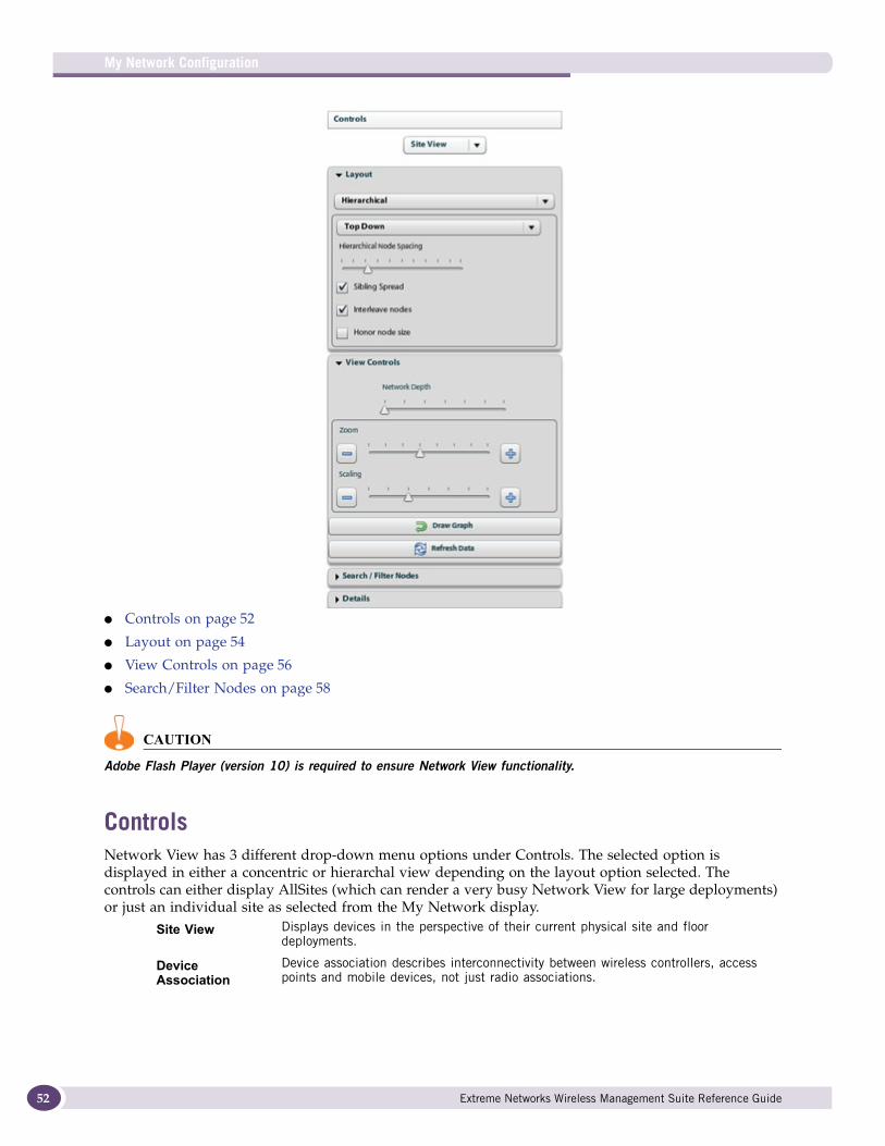
My Network Configuration
52
● Controls on page 52
● Layout on page 54
● View Controls on page 56
● Search/Filter Nodes on page 58
CAUTION
Adobe Flash Player (version 10) is required to ensure Network View functionality.
ControlsNetwork View has 3 different drop-down menu options under Controls. The selected option is displayed in either a concentric or hierarchal view depending on the layout option selected. The controls can either display AllSites (which can render a very busy Network View for large deployments) or just an individual site as selected from the My Network display.
Site View Displays devices in the perspective of their current physical site and floor deployments.
Device Association
Device association describes interconnectivity between wireless controllers, access points and mobile devices, not just radio associations.
Extreme Networks Wireless Management Suite Reference Guide
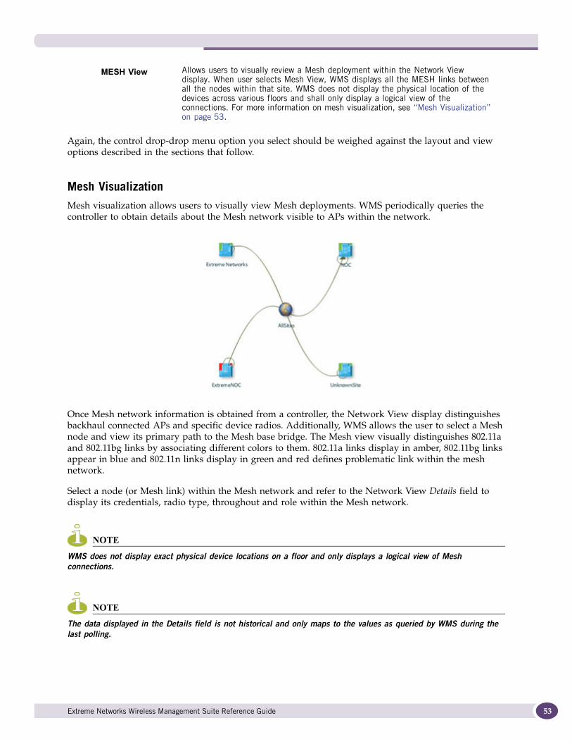
Again, the control drop-drop menu option you select should be weighed against the layout and view options described in the sections that follow.
Mesh Visualization Mesh visualization allows users to visually view Mesh deployments. WMS periodically queries the controller to obtain details about the Mesh network visible to APs within the network.
Once Mesh network information is obtained from a controller, the Network View display distinguishes backhaul connected APs and specific device radios. Additionally, WMS allows the user to select a Mesh node and view its primary path to the Mesh base bridge. The Mesh view visually distinguishes 802.11a and 802.11bg links by associating different colors to them. 802.11a links display in amber, 802.11bg links appear in blue and 802.11n links display in green and red defines problematic link within the mesh network.
Select a node (or Mesh link) within the Mesh network and refer to the Network View Details field to display its credentials, radio type, throughout and role within the Mesh network.
NOTE
WMS does not display exact physical device locations on a floor and only displays a logical view of Mesh connections.
NOTE
The data displayed in the Details field is not historical and only maps to the values as queried by WMS during the last polling.
MESH View Allows users to visually review a Mesh deployment within the Network View display. When user selects Mesh View, WMS displays all the MESH links between all the nodes within that site. WMS does not display the physical location of the devices across various floors and shall only display a logical view of the connections. For more information on mesh visualization, see “Mesh Visualization” on page 53.
Extreme Networks Wireless Management Suite Reference Guide 53
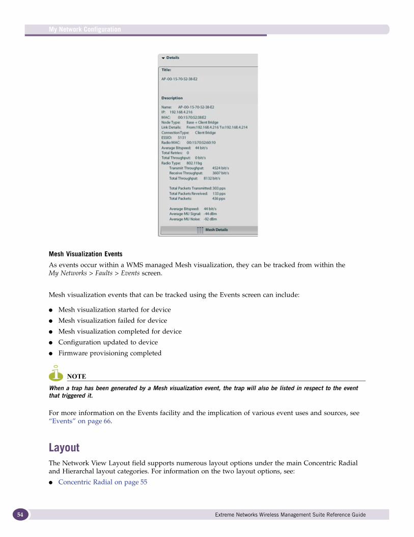
My Network Configuration
54
Mesh Visualization Events
As events occur within a WMS managed Mesh visualization, they can be tracked from within the My Networks > Faults > Events screen.
Mesh visualization events that can be tracked using the Events screen can include:
● Mesh visualization started for device
● Mesh visualization failed for device
● Mesh visualization completed for device
● Configuration updated to device
● Firmware provisioning completed
NOTE
When a trap has been generated by a Mesh visualization event, the trap will also be listed in respect to the event that triggered it.
For more information on the Events facility and the implication of various event uses and sources, see “Events” on page 66.
LayoutThe Network View Layout field supports numerous layout options under the main Concentric Radial and Hierarchal layout categories. For information on the two layout options, see:
● Concentric Radial on page 55
Extreme Networks Wireless Management Suite Reference Guide
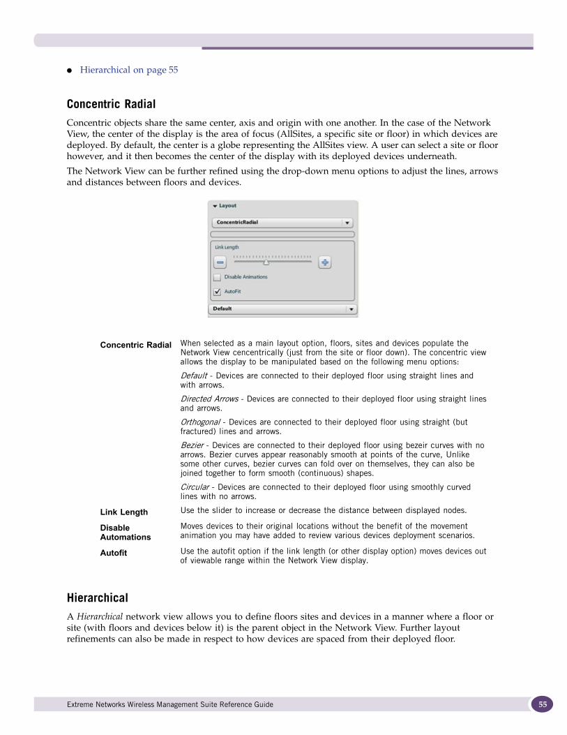
● Hierarchical on page 55
Concentric RadialConcentric objects share the same center, axis and origin with one another. In the case of the Network View, the center of the display is the area of focus (AllSites, a specific site or floor) in which devices are deployed. By default, the center is a globe representing the AllSites view. A user can select a site or floor however, and it then becomes the center of the display with its deployed devices underneath.
The Network View can be further refined using the drop-down menu options to adjust the lines, arrows and distances between floors and devices.
HierarchicalA Hierarchical network view allows you to define floors sites and devices in a manner where a floor or site (with floors and devices below it) is the parent object in the Network View. Further layout refinements can also be made in respect to how devices are spaced from their deployed floor.
Concentric Radial When selected as a main layout option, floors, sites and devices populate the Network View cencentrically (just from the site or floor down). The concentric view allows the display to be manipulated based on the following menu options:
Default - Devices are connected to their deployed floor using straight lines and with arrows.
Directed Arrows - Devices are connected to their deployed floor using straight lines and arrows.
Orthogonal - Devices are connected to their deployed floor using straight (but fractured) lines and arrows.
Bezier - Devices are connected to their deployed floor using bezeir curves with no arrows. Bezier curves appear reasonably smooth at points of the curve, Unlike some other curves, bezier curves can fold over on themselves, they can also be joined together to form smooth (continuous) shapes.
Circular - Devices are connected to their deployed floor using smoothly curved lines with no arrows.
Link Length Use the slider to increase or decrease the distance between displayed nodes.
Disable Automations
Moves devices to their original locations without the benefit of the movement animation you may have added to review various devices deployment scenarios.
Autofit Use the autofit option if the link length (or other display option) moves devices out of viewable range within the Network View display.
Extreme Networks Wireless Management Suite Reference Guide 55
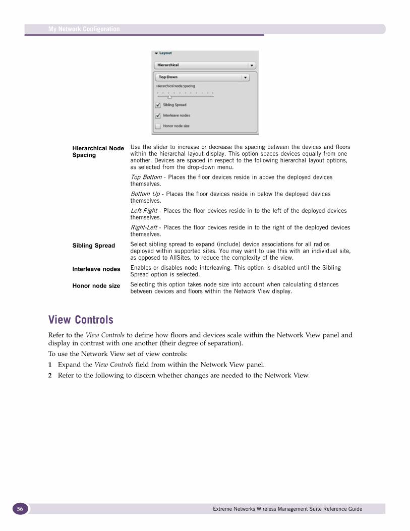
My Network Configuration
56
View ControlsRefer to the View Controls to define how floors and devices scale within the Network View panel and display in contrast with one another (their degree of separation).
To use the Network View set of view controls:
1 Expand the View Controls field from within the Network View panel.
2 Refer to the following to discern whether changes are needed to the Network View.
Hierarchical Node Spacing
Use the slider to increase or decrease the spacing between the devices and floors within the hierarchal layout display. This option spaces devices equally from one another. Devices are spaced in respect to the following hierarchal layout options, as selected from the drop-down menu.
Top Bottom - Places the floor devices reside in above the deployed devices themselves.
Bottom Up - Places the floor devices reside in below the deployed devices themselves.
Left-Right - Places the floor devices reside in to the left of the deployed devices themselves.
Right-Left - Places the floor devices reside in to the right of the deployed devices themselves.
Sibling Spread Select sibling spread to expand (include) device associations for all radios deployed within supported sites. You may want to use this with an individual site, as opposed to AllSites, to reduce the complexity of the view.
Interleave nodes Enables or disables node interleaving. This option is disabled until the Sibling Spread option is selected.
Honor node size Selecting this option takes node size into account when calculating distances between devices and floors within the Network View display.
Extreme Networks Wireless Management Suite Reference Guide
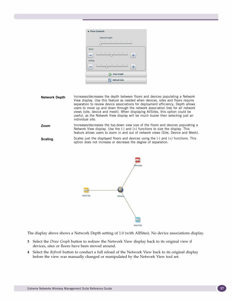
The display above shows a Network Depth setting of 1.0 (with AllSites). No device associations display.
3 Select the Draw Graph button to redraw the Network View display back to its original view if devices, sites or floors have been moved around.
4 Select the Refresh button to conduct a full reload of the Network View back to its original display before the view was manually changed or manipulated by the Network View tool set.
Network Depth Increases/decreases the depth between floors and devices populating a Network View display. Use this feature as needed when devices, sites and floors require separation to review device associations for deployment efficiency. Depth allows users to move up and down through the network association tree for all network views (site, device and mesh). When displaying AllSites, this option could be useful, as the Network View display will be much busier then selecting just an individual site.
Zoom Increases/decreases the top-down view size of the floors and devices populating a Network View display. Use the (-) and (+) functions to size the display. This feature allows users to zoom in and out of network views (Site, Device and Mesh).
Scaling Scales just the displayed floors and devices using the (-) and (+) functions. This option does not increase or decrease the degree of separation.
Extreme Networks Wireless Management Suite Reference Guide 57
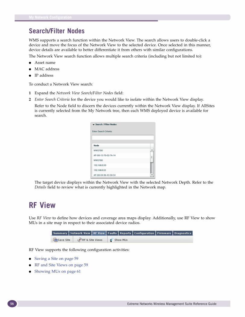
My Network Configuration
58
Search/Filter NodesWMS supports a search function within the Network View. The search allows users to double-click a device and move the focus of the Network View to the selected device. Once selected in this manner, device details are available to better differentiate it from others with similar configurations.
The Network View search function allows multiple search criteria (including but not limited to):
● Asset name
● MAC address
● IP address
To conduct a Network View search:
1 Expand the Network View Search/Filter Nodes field:
2 Enter Search Criteria for the device you would like to isolate within the Network View display.
Refer to the Node field to discern the devices currently within the Network View display. If AllSites is currently selected from the My Network tree, then each WMS deployed device is available for search.
The target device displays within the Network View with the selected Network Depth. Refer to the Details field to review what is currently highlighted in the Network map.
RF ViewUse RF View to define how devices and coverage area maps display. Additionally, use RF View to show MUs in a site map in respect to their associated device radios.
RF View supports the following configuration activities:
● Saving a Site on page 59
● RF and Site Views on page 59
● Showing MUs on page 61
Extreme Networks Wireless Management Suite Reference Guide
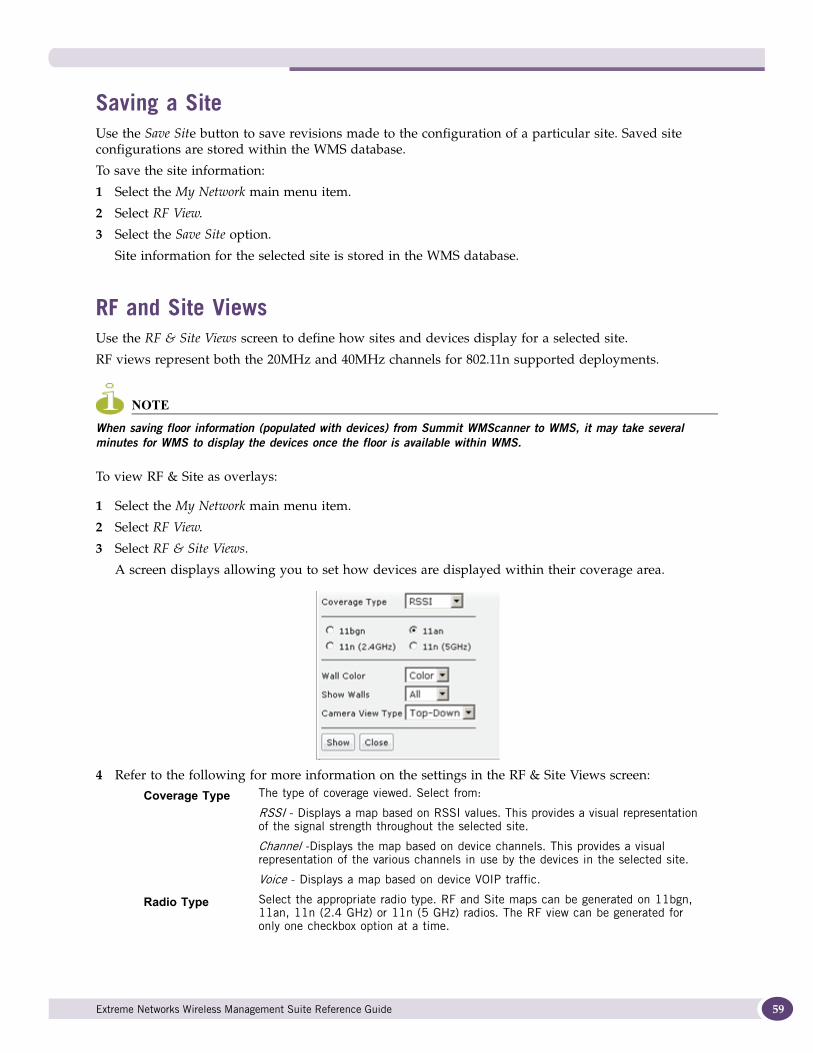
Saving a SiteUse the Save Site button to save revisions made to the configuration of a particular site. Saved site configurations are stored within the WMS database.
To save the site information:
1 Select the My Network main menu item.
2 Select RF View.
3 Select the Save Site option.
Site information for the selected site is stored in the WMS database.
RF and Site ViewsUse the RF & Site Views screen to define how sites and devices display for a selected site.
RF views represent both the 20MHz and 40MHz channels for 802.11n supported deployments.
NOTE
When saving floor information (populated with devices) from Summit WMScanner to WMS, it may take several minutes for WMS to display the devices once the floor is available within WMS.
To view RF & Site as overlays:
1 Select the My Network main menu item.
2 Select RF View.
3 Select RF & Site Views.
A screen displays allowing you to set how devices are displayed within their coverage area.
4 Refer to the following for more information on the settings in the RF & Site Views screen:
Coverage Type The type of coverage viewed. Select from:
RSSI - Displays a map based on RSSI values. This provides a visual representation of the signal strength throughout the selected site.
Channel -Displays the map based on device channels. This provides a visual representation of the various channels in use by the devices in the selected site.
Voice - Displays a map based on device VOIP traffic.
Radio Type Select the appropriate radio type. RF and Site maps can be generated on 11bgn, 11an, 11n (2.4 GHz) or 11n (5 GHz) radios. The RF view can be generated for only one checkbox option at a time.
Extreme Networks Wireless Management Suite Reference Guide 59
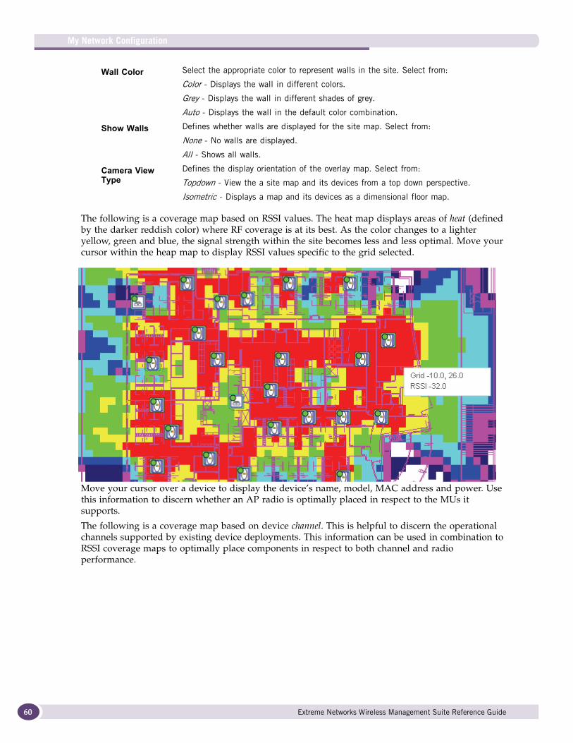
My Network Configuration
60
The following is a coverage map based on RSSI values. The heat map displays areas of heat (defined by the darker reddish color) where RF coverage is at its best. As the color changes to a lighter yellow, green and blue, the signal strength within the site becomes less and less optimal. Move your cursor within the heap map to display RSSI values specific to the grid selected.
Move your cursor over a device to display the device’s name, model, MAC address and power. Use this information to discern whether an AP radio is optimally placed in respect to the MUs it supports.
The following is a coverage map based on device channel. This is helpful to discern the operational channels supported by existing device deployments. This information can be used in combination to RSSI coverage maps to optimally place components in respect to both channel and radio performance.
Wall Color Select the appropriate color to represent walls in the site. Select from:
Color - Displays the wall in different colors.
Grey - Displays the wall in different shades of grey.
Auto - Displays the wall in the default color combination.
Show Walls Defines whether walls are displayed for the site map. Select from:
None - No walls are displayed.
All - Shows all walls.
Camera View Type
Defines the display orientation of the overlay map. Select from:
Topdown - View the a site map and its devices from a top down perspective.
Isometric - Displays a map and its devices as a dimensional floor map.
Extreme Networks Wireless Management Suite Reference Guide
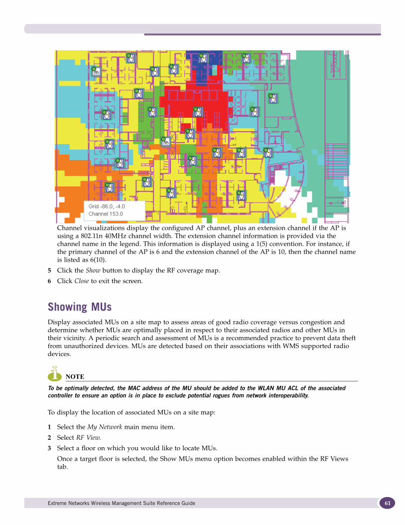
Channel visualizations display the configured AP channel, plus an extension channel if the AP is using a 802.11n 40MHz channel width. The extension channel information is provided via the channel name in the legend. This information is displayed using a 1(5) convention. For instance, if the primary channel of the AP is 6 and the extension channel of the AP is 10, then the channel name is listed as 6(10).
5 Click the Show button to display the RF coverage map.
6 Click Close to exit the screen.
Showing MUsDisplay associated MUs on a site map to assess areas of good radio coverage versus congestion and determine whether MUs are optimally placed in respect to their associated radios and other MUs in their vicinity. A periodic search and assessment of MUs is a recommended practice to prevent data theft from unauthorized devices. MUs are detected based on their associations with WMS supported radio devices.
NOTE
To be optimally detected, the MAC address of the MU should be added to the WLAN MU ACL of the associated controller to ensure an option is in place to exclude potential rogues from network interoperability.
To display the location of associated MUs on a site map:
1 Select the My Network main menu item.
2 Select RF View.
3 Select a floor on which you would like to locate MUs.
Once a target floor is selected, the Show MUs menu option becomes enabled within the RF Views tab.
Extreme Networks Wireless Management Suite Reference Guide 61
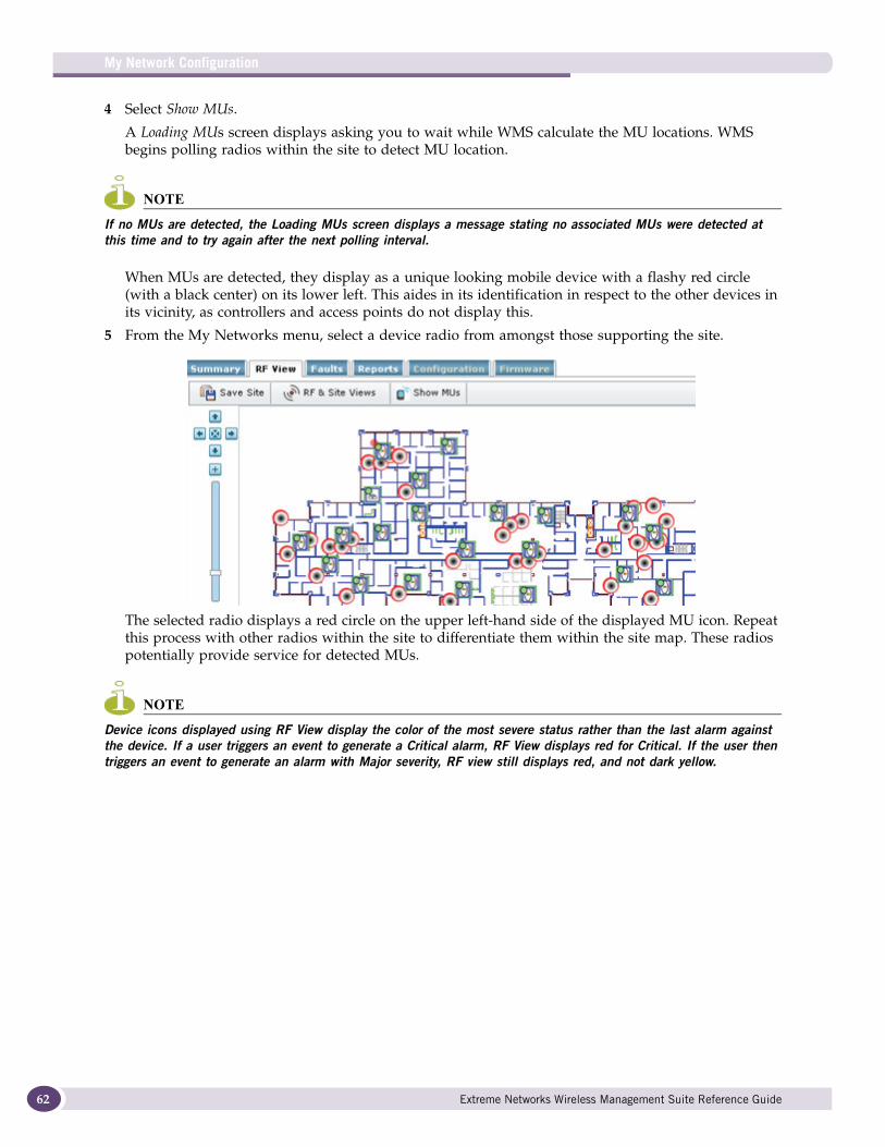
My Network Configuration
62
4 Select Show MUs.
A Loading MUs screen displays asking you to wait while WMS calculate the MU locations. WMS begins polling radios within the site to detect MU location.
NOTE
If no MUs are detected, the Loading MUs screen displays a message stating no associated MUs were detected at this time and to try again after the next polling interval.
When MUs are detected, they display as a unique looking mobile device with a flashy red circle (with a black center) on its lower left. This aides in its identification in respect to the other devices in its vicinity, as controllers and access points do not display this.
5 From the My Networks menu, select a device radio from amongst those supporting the site.
The selected radio displays a red circle on the upper left-hand side of the displayed MU icon. Repeat this process with other radios within the site to differentiate them within the site map. These radios potentially provide service for detected MUs.
NOTE
Device icons displayed using RF View display the color of the most severe status rather than the last alarm against the device. If a user triggers an event to generate a Critical alarm, RF View displays red for Critical. If the user then triggers an event to generate an alarm with Major severity, RF view still displays red, and not dark yellow.
Extreme Networks Wireless Management Suite Reference Guide
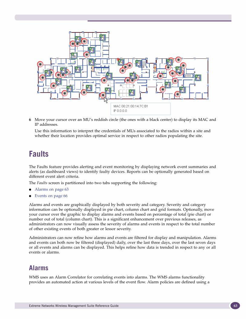
6 Move your cursor over an MU’s reddish circle (the ones with a black center) to display its MAC and IP addresses.
Use this information to interpret the credentials of MUs associated to the radios within a site and whether their location provides optimal service in respect to other radios populating the site.
FaultsThe Faults feature provides alerting and event monitoring by displaying network event summaries and alerts (as dashboard views) to identify faulty devices. Reports can be optionally generated based on different event alert criteria.
The Faults screen is partitioned into two tabs supporting the following:
● Alarms on page 63
● Events on page 66
Alarms and events are graphically displayed by both severity and category. Severity and category information can be optionally displayed in pie chart, column chart and grid formats. Optionally, move your cursor over the graphic to display alarms and events based on percentage of total (pie chart) or number out of total (column chart). This is a significant enhancement over previous releases, as administrators can now visually assess the severity of alarms and events in respect to the total number of other existing events of both greater or lessor severity.
Administrators can now refine how alarms and events are filtered for display and manipulation. Alarms and events can both now be filtered (displayed) daily, over the last three days, over the last seven days or all events and alarms can be displayed. This helps refine how data is trended in respect to any or all events or alarms.
Alarms WMS uses an Alarm Correlator for correlating events into alarms. The WMS alarms functionality provides an automated action at various levels of the event flow. Alarm policies are defined using a
Extreme Networks Wireless Management Suite Reference Guide 63
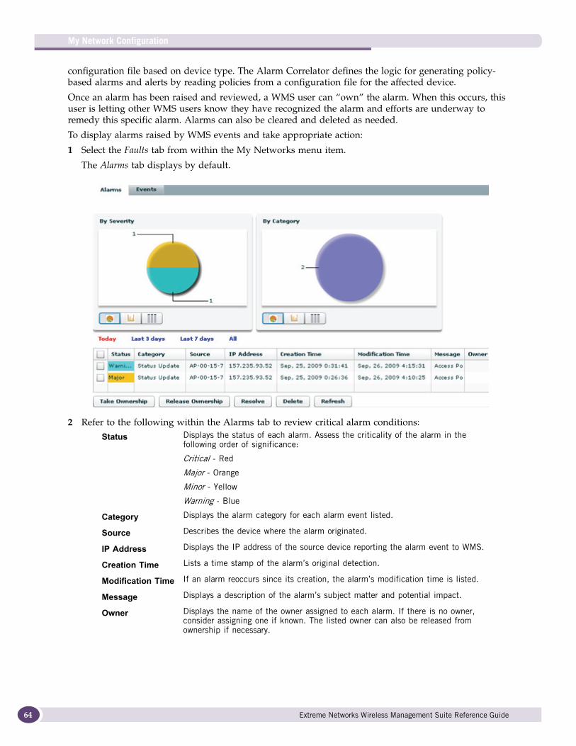
My Network Configuration
64
configuration file based on device type. The Alarm Correlator defines the logic for generating policy-based alarms and alerts by reading policies from a configuration file for the affected device.
Once an alarm has been raised and reviewed, a WMS user can “own” the alarm. When this occurs, this user is letting other WMS users know they have recognized the alarm and efforts are underway to remedy this specific alarm. Alarms can also be cleared and deleted as needed.
To display alarms raised by WMS events and take appropriate action:
1 Select the Faults tab from within the My Networks menu item.
The Alarms tab displays by default.
2 Refer to the following within the Alarms tab to review critical alarm conditions:
Status Displays the status of each alarm. Assess the criticality of the alarm in the following order of significance:
Critical - Red
Major - Orange
Minor - Yellow
Warning - Blue
Category Displays the alarm category for each alarm event listed.
Source Describes the device where the alarm originated.
IP Address Displays the IP address of the source device reporting the alarm event to WMS.
Creation Time Lists a time stamp of the alarm’s original detection.
Modification Time If an alarm reoccurs since its creation, the alarm’s modification time is listed.
Message Displays a description of the alarm’s subject matter and potential impact.
Owner Displays the name of the owner assigned to each alarm. If there is no owner, consider assigning one if known. The listed owner can also be released from ownership if necessary.
Extreme Networks Wireless Management Suite Reference Guide
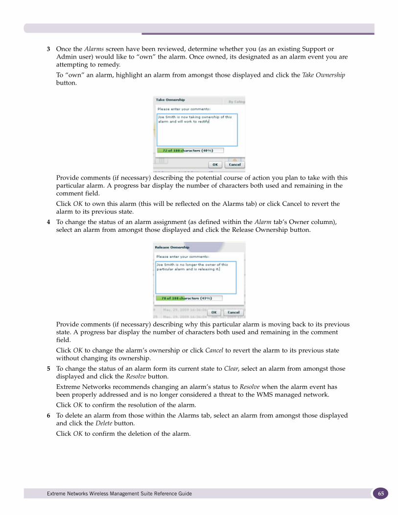
3 Once the Alarms screen have been reviewed, determine whether you (as an existing Support or Admin user) would like to “own” the alarm. Once owned, its designated as an alarm event you are attempting to remedy.
To “own” an alarm, highlight an alarm from amongst those displayed and click the Take Ownership button.
Provide comments (if necessary) describing the potential course of action you plan to take with this particular alarm. A progress bar display the number of characters both used and remaining in the comment field.
Click OK to own this alarm (this will be reflected on the Alarms tab) or click Cancel to revert the alarm to its previous state.
4 To change the status of an alarm assignment (as defined within the Alarm tab’s Owner column), select an alarm from amongst those displayed and click the Release Ownership button.
Provide comments (if necessary) describing why this particular alarm is moving back to its previous state. A progress bar display the number of characters both used and remaining in the comment field.
Click OK to change the alarm’s ownership or click Cancel to revert the alarm to its previous state without changing its ownership.
5 To change the status of an alarm form its current state to Clear, select an alarm from amongst those displayed and click the Resolve button.
Extreme Networks recommends changing an alarm’s status to Resolve when the alarm event has been properly addressed and is no longer considered a threat to the WMS managed network.
Click OK to confirm the resolution of the alarm.
6 To delete an alarm from those within the Alarms tab, select an alarm from amongst those displayed and click the Delete button.
Click OK to confirm the deletion of the alarm.
Extreme Networks Wireless Management Suite Reference Guide 65
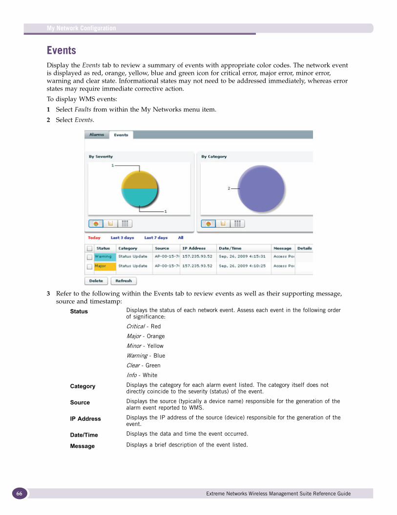
My Network Configuration
66
EventsDisplay the Events tab to review a summary of events with appropriate color codes. The network event is displayed as red, orange, yellow, blue and green icon for critical error, major error, minor error, warning and clear state. Informational states may not need to be addressed immediately, whereas error states may require immediate corrective action.
To display WMS events:
1 Select Faults from within the My Networks menu item.
2 Select Events.
3 Refer to the following within the Events tab to review events as well as their supporting message, source and timestamp:
Status Displays the status of each network event. Assess each event in the following order of significance:
Critical - Red
Major - Orange
Minor - Yellow
Warning - Blue
Clear - Green
Info - White
Category Displays the category for each alarm event listed. The category itself does not directly coincide to the severity (status) of the event.
Source Displays the source (typically a device name) responsible for the generation of the alarm event reported to WMS.
IP Address Displays the IP address of the source (device) responsible for the generation of the event.
Date/Time Displays the data and time the event occurred.
Message Displays a brief description of the event listed.
Extreme Networks Wireless Management Suite Reference Guide

Those events raised representing alarms are separately tracked for better event troubleshooting. Refer to the Alarms tab as needed to assess critical conditions flagged by WMS.
4 Select an event from amongst those listed and select the Delete button to remove from this events from the list displayed within the Events tab.
5 Optionally select the Refresh button to re-populate the events list with new events that may have occurred since the list was last populated.
ReportsWMS contains a list of pre-defined reports, relevant to the device models supported. When a user selects devices, a list of applicable pre-defined reports is available to the user for that device family. The user can also select and customize reports for a specific time periods (with a beginning and ending date) to further refine report content in respect to a defined reporting interval.
The data collected by WMS can be reported in raw-data and graphical formats. The data collected within a WMS report is periodically polled by the MIB structures supporting WMS device monitoring and data collection activities.
The WMS reporting screen is portioned into three tabs supporting:
● Viewing Pre-Defined Reports on page 67
● Live Reporting on page 71
NOTE
Reports generated by WMS provide information for a trended (historical) period defined by the user. WMS does not display report content in real-time or as actual device performance is positively or negatively impacted. The default data refresh and polling interval in once an hour. However, the user has the option of changing the polling interval for data collection.
Viewing Pre-Defined ReportsRefer to the information within the Pre-Defined tab to review a series of performance reports for a selected device. Reports populate in spreadsheet format. Refer to the Pre-Defined tab’s Date Selection Settings: field to determine the interval data is collected for the report.
To display report information for a selected device model and determine the interval subsequent report data is collected:
1 Select the My Network main menu item.
2 Expand an existing site and select a target device for performance report population.
3 Select Reports.
The Pre-Defined tab displays device performance trending reports populated with information collected for the day (default interval).
Details If an event displays a Details link, select it to display a View Details screen. The variable name and key SNMP information display to help assess how this event was triggered.
Extreme Networks Wireless Management Suite Reference Guide 67
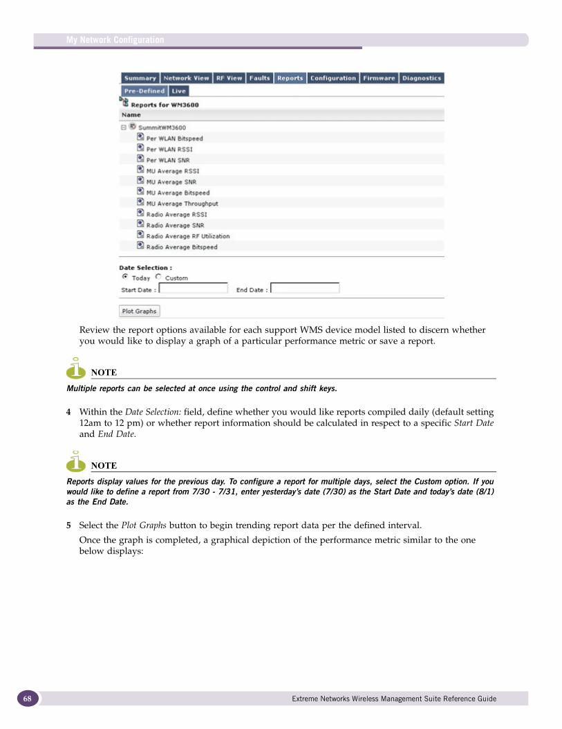
My Network Configuration
68
Review the report options available for each support WMS device model listed to discern whether you would like to display a graph of a particular performance metric or save a report.
NOTE
Multiple reports can be selected at once using the control and shift keys.
4 Within the Date Selection: field, define whether you would like reports compiled daily (default setting 12am to 12 pm) or whether report information should be calculated in respect to a specific Start Date and End Date.
NOTE
Reports display values for the previous day. To configure a report for multiple days, select the Custom option. If you would like to define a report from 7/30 - 7/31, enter yesterday’s date (7/30) as the Start Date and today’s date (8/1) as the End Date.
5 Select the Plot Graphs button to begin trending report data per the defined interval.
Once the graph is completed, a graphical depiction of the performance metric similar to the one below displays:
Extreme Networks Wireless Management Suite Reference Guide

You have the option of selecting a report polling period and displaying a value for the report option selected within Pre-Defined tab. The selected reporting period appears as an orange dot, with the time stamp and value calculated by WMS for that option displayed in orange boxes.
Use the cursor slider bar at the bottom of the graph to navigate to specific time periods as needed to better assess the time trends of the selected report.
Once the content of each report has been reviewed, the report’s content can be saved as an individual spreadsheet file, reviewed in a tabular (raw data) format or scheduled at a different interval.
Saving Individual Reports Once reviewed, the contents of an individual report can be saved (archived) in spreadsheet format to location you designate.
To save the contents of a WMS generated report:
1 Select an existing report option from amongst those displayed for a particular device model.
2 Select the Plot Graphs option.
3 Select the Download CSV option associated with the target report.
Extreme Networks Wireless Management Suite Reference Guide 69
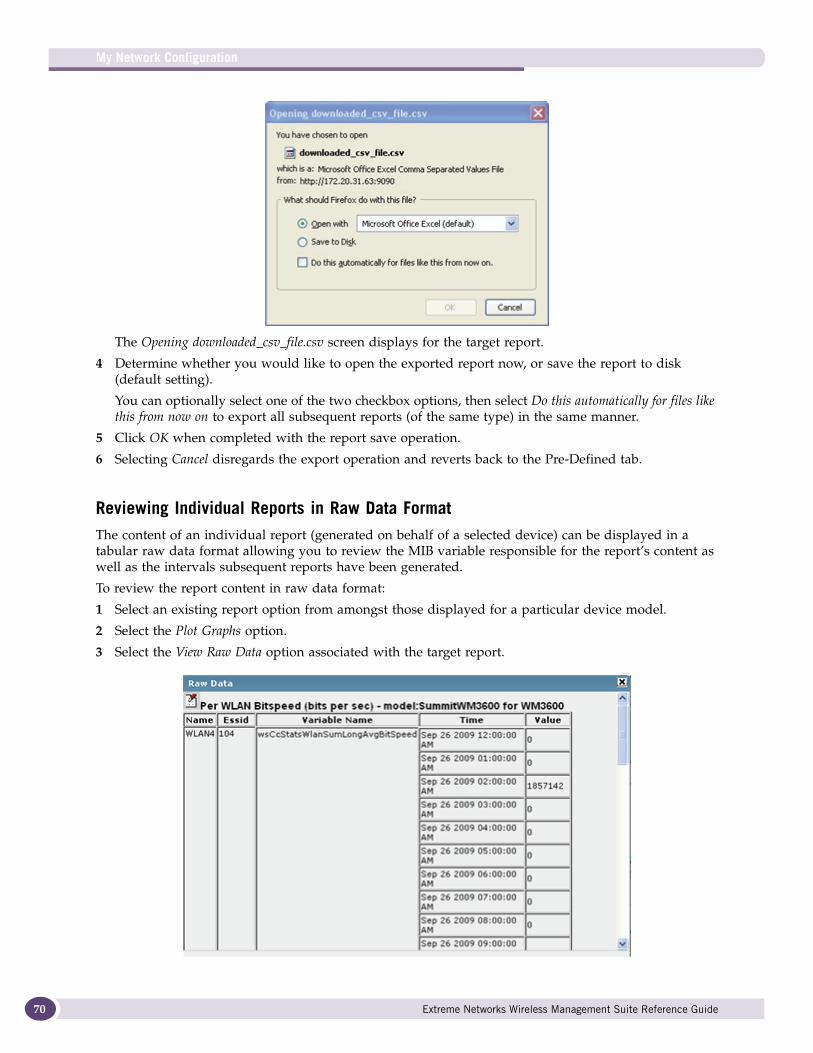
My Network Configuration
70
The Opening downloaded_csv_file.csv screen displays for the target report.
4 Determine whether you would like to open the exported report now, or save the report to disk (default setting).
You can optionally select one of the two checkbox options, then select Do this automatically for files like this from now on to export all subsequent reports (of the same type) in the same manner.
5 Click OK when completed with the report save operation.
6 Selecting Cancel disregards the export operation and reverts back to the Pre-Defined tab.
Reviewing Individual Reports in Raw Data FormatThe content of an individual report (generated on behalf of a selected device) can be displayed in a tabular raw data format allowing you to review the MIB variable responsible for the report’s content as well as the intervals subsequent reports have been generated.
To review the report content in raw data format:
1 Select an existing report option from amongst those displayed for a particular device model.
2 Select the Plot Graphs option.
3 Select the View Raw Data option associated with the target report.
Extreme Networks Wireless Management Suite Reference Guide
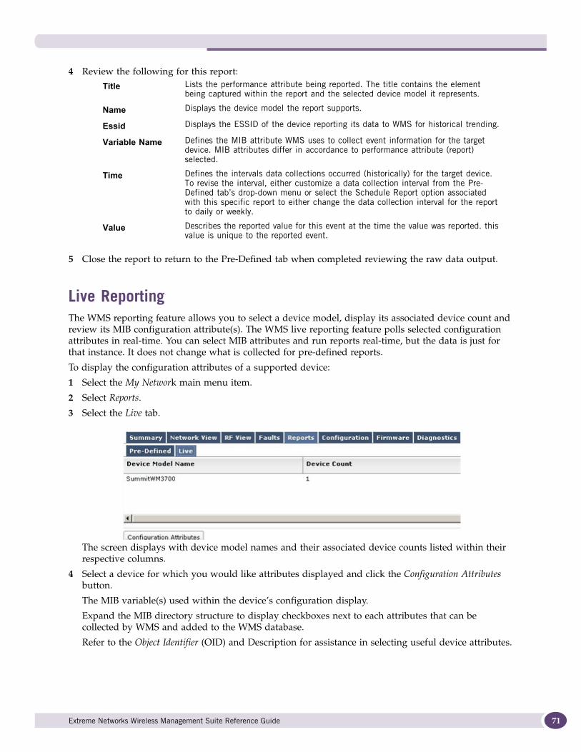
4 Review the following for this report:
5 Close the report to return to the Pre-Defined tab when completed reviewing the raw data output.
Live ReportingThe WMS reporting feature allows you to select a device model, display its associated device count and review its MIB configuration attribute(s). The WMS live reporting feature polls selected configuration attributes in real-time. You can select MIB attributes and run reports real-time, but the data is just for that instance. It does not change what is collected for pre-defined reports.
To display the configuration attributes of a supported device:
1 Select the My Network main menu item.
2 Select Reports.
3 Select the Live tab.
The screen displays with device model names and their associated device counts listed within their respective columns.
4 Select a device for which you would like attributes displayed and click the Configuration Attributes button.
The MIB variable(s) used within the device’s configuration display.
Expand the MIB directory structure to display checkboxes next to each attributes that can be collected by WMS and added to the WMS database.
Refer to the Object Identifier (OID) and Description for assistance in selecting useful device attributes.
Title Lists the performance attribute being reported. The title contains the element being captured within the report and the selected device model it represents.
Name Displays the device model the report supports.
Essid Displays the ESSID of the device reporting its data to WMS for historical trending.
Variable Name Defines the MIB attribute WMS uses to collect event information for the target device. MIB attributes differ in accordance to performance attribute (report) selected.
Time Defines the intervals data collections occurred (historically) for the target device. To revise the interval, either customize a data collection interval from the Pre-Defined tab’s drop-down menu or select the Schedule Report option associated with this specific report to either change the data collection interval for the report to daily or weekly.
Value Describes the reported value for this event at the time the value was reported. this value is unique to the reported event.
Extreme Networks Wireless Management Suite Reference Guide 71
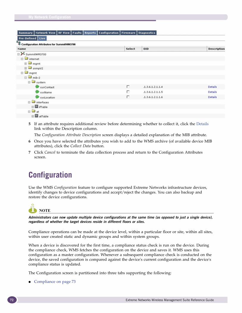
My Network Configuration
72
5 If an attribute requires additional review before determining whether to collect it, click the Details link within the Description column.
The Configuration Attribute Description screen displays a detailed explanation of the MIB attribute.
6 Once you have selected the attributes you wish to add to the WMS archive (of available device MIB attributes), click the Collect Data button.
7 Click Cancel to terminate the data collection process and return to the Configuration Attributes screen.
ConfigurationUse the WMS Configuration feature to configure supported Extreme Networks infrastructure devices, identify changes to device configurations and accept/reject the changes. You can also backup and restore the device configurations.
NOTE
Administrators can now update multiple device configurations at the same time (as opposed to just a single device), regardless of whether the target devices reside in different floors or sites.
Compliance operations can be made at the device level, within a particular floor or site, within all sites, within user created static and dynamic groups and within system groups.
When a device is discovered for the first time, a compliance status check is run on the device. During the compliance check, WMS fetches the configuration on the device and saves it. WMS uses this configuration as a master configuration. Whenever a subsequent compliance check is conducted on the device, the saved configuration is compared against the device's current configuration and the device's compliance status is updated.
The Configuration screen is partitioned into three tabs supporting the following:
● Compliance on page 73
Extreme Networks Wireless Management Suite Reference Guide
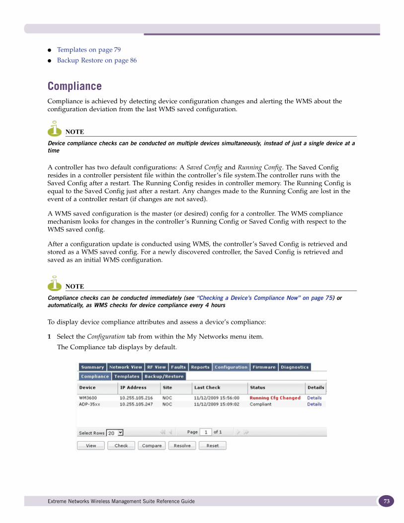
● Templates on page 79
● Backup Restore on page 86
ComplianceCompliance is achieved by detecting device configuration changes and alerting the WMS about the configuration deviation from the last WMS saved configuration.
NOTE
Device compliance checks can be conducted on multiple devices simultaneously, instead of just a single device at a time
A controller has two default configurations: A Saved Config and Running Config. The Saved Config resides in a controller persistent file within the controller’s file system.The controller runs with the Saved Config after a restart. The Running Config resides in controller memory. The Running Config is equal to the Saved Config just after a restart. Any changes made to the Running Config are lost in the event of a controller restart (if changes are not saved).
A WMS saved configuration is the master (or desired) config for a controller. The WMS compliance mechanism looks for changes in the controller’s Running Config or Saved Config with respect to the WMS saved config.
After a configuration update is conducted using WMS, the controller’s Saved Config is retrieved and stored as a WMS saved config. For a newly discovered controller, the Saved Config is retrieved and saved as an initial WMS configuration.
NOTE
Compliance checks can be conducted immediately (see “Checking a Device’s Compliance Now” on page 75) or automatically, as WMS checks for device compliance every 4 hours
To display device compliance attributes and assess a device’s compliance:
1 Select the Configuration tab from within the My Networks menu item.
The Compliance tab displays by default.
Extreme Networks Wireless Management Suite Reference Guide 73
My Network Configuration
74
Refer to the following to discern whether a listed device configuration is compliant with its expected configuration or in conflict:
Once the information within the Compliance tab is reviewed, determine whether the following additional actions are required:
● Viewing a Device’s Configuration on page 74
● Checking a Device’s Compliance Now on page 75
● Assessing a Device’s Configuration Differential on page 76
● Resolving a Non Compliant Device Configuration on page 76
● Resetting Device Compliance on page 77
● Viewing Device Compliance Details on page 78
Viewing a Device’s ConfigurationA device can be selected and its last saved WMS configuration viewed to assess the configuration used by WMS to interpret the status displayed within the Compliance tab.
To display a device’s last saved WMS configuration:
1 Select the Configuration tab from within the My Networks menu item.
2 Highlight a device (controller or other) from within the Compliance tab.
3 Click the View button.
The View Device Configuration screen displays with the selected device’s last saved WMS configuration. This is the configuration WMS compares to the device’s current configuration (polled by WMS) to assess whether a conflict exists.
Device Displays the name assigned to the device. WMS periodically polls to check whether the device is compliant. This interval is internal to WMS and cannot be modified.
IP Address Displays the IP address of each listed device.
Site Displays the name of the WMS managed site within which a target device resides. SNMP polls the listed device within this site (on behalf of WMS) to assess whether its configuration is in conflict.
Last Check Displays a timestamp of the time WMS polled the device to assess compliance.
Status The following status states display when the compliance check is in progress or if a device is not reachable. Potential devices statuses include:
Compliant - The device’s current configuration is the same as the configuration maintained by WMS for this device model. This configuration is defined by WMS as desired for this device model until replaced by a more optimal one.
Unknown - The compliance status is Unknown if there is an issue with the relay server or device and compliance cannot be determined.
Saved Cfg Changed - WMS has determined the device’s saved config is different from the saved configuration. This is important, as this different Saved Config will be invoked the next time the device boots. This state applies to not only controller products, but Access Points as well.
Running Cfg Changed - WMS has determined a WM3400, WM3600 or WM3700’s running-config (current configuration) is different from the configuration saved by WMS. Consider changing the controller’s running-config back to the configuration saved by WMS or determine if the controller’s running-config has attributes making it better suited for compliance.
Details Click the Details link associated with each supported device to review the details of a device’s compliance check. Unsupported device’s do not display a Details link.
Extreme Networks Wireless Management Suite Reference Guide
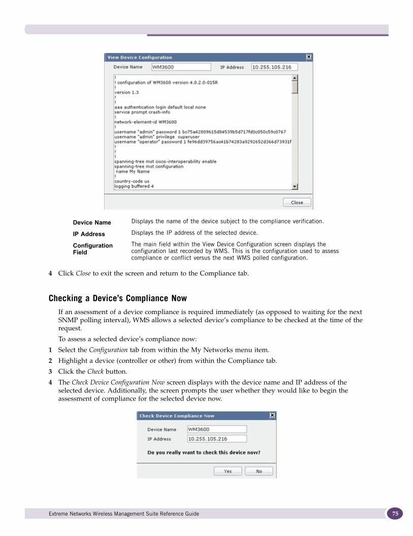
4 Click Close to exit the screen and return to the Compliance tab.
Checking a Device’s Compliance NowIf an assessment of a device compliance is required immediately (as opposed to waiting for the next SNMP polling interval), WMS allows a selected device’s compliance to be checked at the time of the request.
To assess a selected device’s compliance now:
1 Select the Configuration tab from within the My Networks menu item.
2 Highlight a device (controller or other) from within the Compliance tab.
3 Click the Check button.
4 The Check Device Configuration Now screen displays with the device name and IP address of the selected device. Additionally, the screen prompts the user whether they would like to begin the assessment of compliance for the selected device now.
Device Name Displays the name of the device subject to the compliance verification.
IP Address Displays the IP address of the selected device.
Configuration Field
The main field within the View Device Configuration screen displays the configuration last recorded by WMS. This is the configuration used to assess compliance or conflict versus the next WMS polled configuration.
Extreme Networks Wireless Management Suite Reference Guide 75
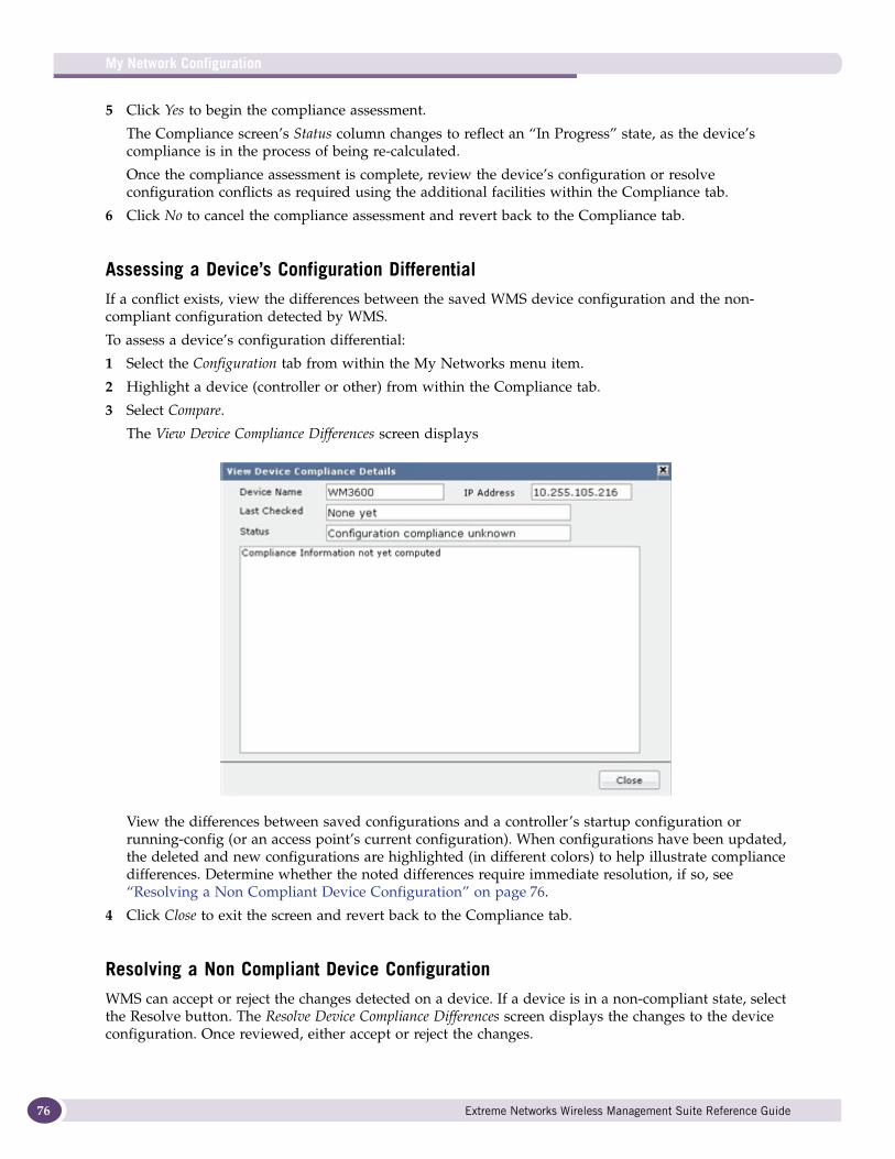
My Network Configuration
76
5 Click Yes to begin the compliance assessment.
The Compliance screen’s Status column changes to reflect an “In Progress” state, as the device’s compliance is in the process of being re-calculated.
Once the compliance assessment is complete, review the device’s configuration or resolve configuration conflicts as required using the additional facilities within the Compliance tab.
6 Click No to cancel the compliance assessment and revert back to the Compliance tab.
Assessing a Device’s Configuration DifferentialIf a conflict exists, view the differences between the saved WMS device configuration and the non-compliant configuration detected by WMS.
To assess a device’s configuration differential:
1 Select the Configuration tab from within the My Networks menu item.
2 Highlight a device (controller or other) from within the Compliance tab.
3 Select Compare.
The View Device Compliance Differences screen displays
View the differences between saved configurations and a controller’s startup configuration or running-config (or an access point’s current configuration). When configurations have been updated, the deleted and new configurations are highlighted (in different colors) to help illustrate compliance differences. Determine whether the noted differences require immediate resolution, if so, see “Resolving a Non Compliant Device Configuration” on page 76.
4 Click Close to exit the screen and revert back to the Compliance tab.
Resolving a Non Compliant Device ConfigurationWMS can accept or reject the changes detected on a device. If a device is in a non-compliant state, select the Resolve button. The Resolve Device Compliance Differences screen displays the changes to the device configuration. Once reviewed, either accept or reject the changes.
Extreme Networks Wireless Management Suite Reference Guide
Accepting the changes updates the Saved Config within WMS and the device becomes compliant. When you reject the changes, WMS copies the saved configuration to device’s start-up configuration and reboots the device.
To resolve a non compliant configuration and save it as the device’s new configuration:
1 Select the Configuration tab from within the My Networks menu item.
2 Highlight a device (controller or other) from within the Compliance tab.
Ensure the selected device requires compliance resolution, as there is no reason to resolve a configuration that’s currently compliant.
3 Select Resolve.
4 Review the Status and the text in the main window, as that describes (in detail) each configuration change that resulted in the compliance differential.
A message displays prompting whether you would like to accept or reject the changed configuration detected by WMS.
5 Click Accept to initiate a job to push the configuration to the device and save the modified configuration as the new WMS saved (and compliant) configuration.
6 Click Reject to initiate a job that pushes the WMS saved configuration back to the device, and either saves it as saved config or as the device’s current configuration.
7 Click Cancel to exit the screen and revert back to the Compliance tab without accepting or rejecting changes to the devices’s configuration.
Resetting Device ComplianceResetting device compliance removes the device’s saved configuration and moves the device to an unknown state.
To reset compliance information for a selected device or a group of devices:
1 Select the Configuration tab from within the My Networks menu item.
2 Select a device (controller or other) from within the Compliance tab.
Optionally select a group of devices, as needed, to reset device compliance collectively.
3 Select Reset.
The Reset Devices Compliance Differences screen displays. You are prompted as to whether you would really like to reset compliance information for the device or group of devices listed.
Extreme Networks Wireless Management Suite Reference Guide 77
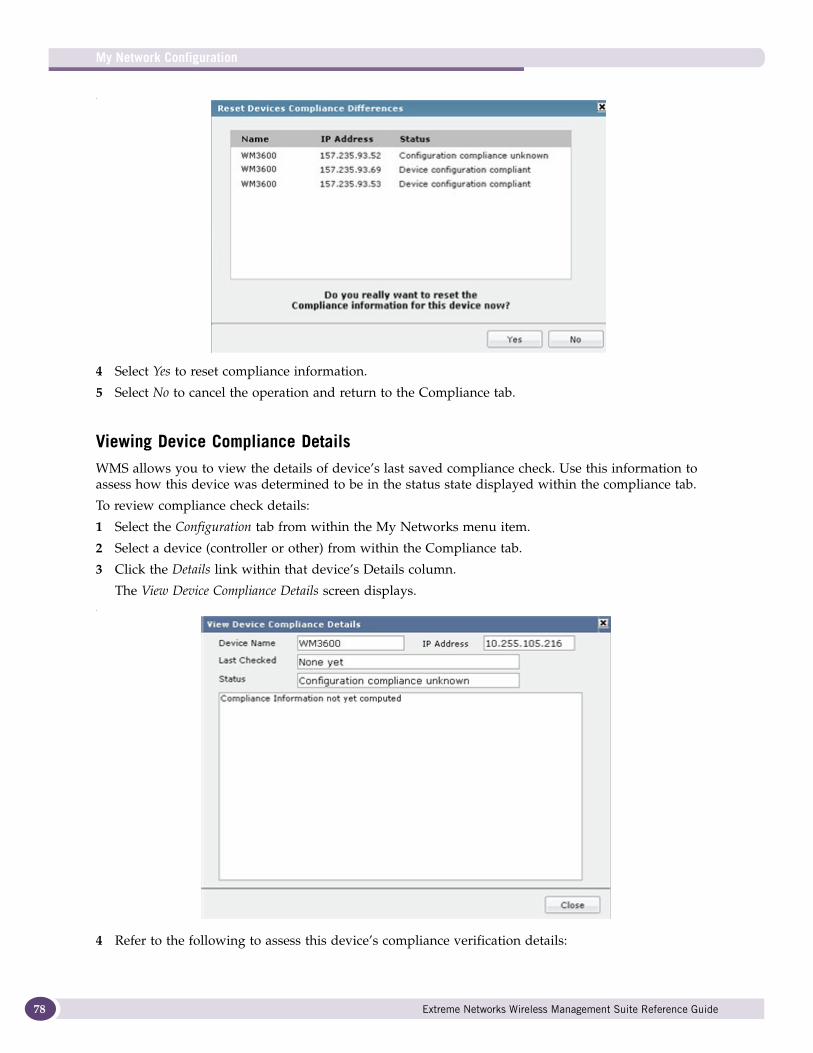
My Network Configuration
78
.
4 Select Yes to reset compliance information.
5 Select No to cancel the operation and return to the Compliance tab.
Viewing Device Compliance DetailsWMS allows you to view the details of device’s last saved compliance check. Use this information to assess how this device was determined to be in the status state displayed within the compliance tab.
To review compliance check details:
1 Select the Configuration tab from within the My Networks menu item.
2 Select a device (controller or other) from within the Compliance tab.
3 Click the Details link within that device’s Details column.
The View Device Compliance Details screen displays..
4 Refer to the following to assess this device’s compliance verification details:
Extreme Networks Wireless Management Suite Reference Guide
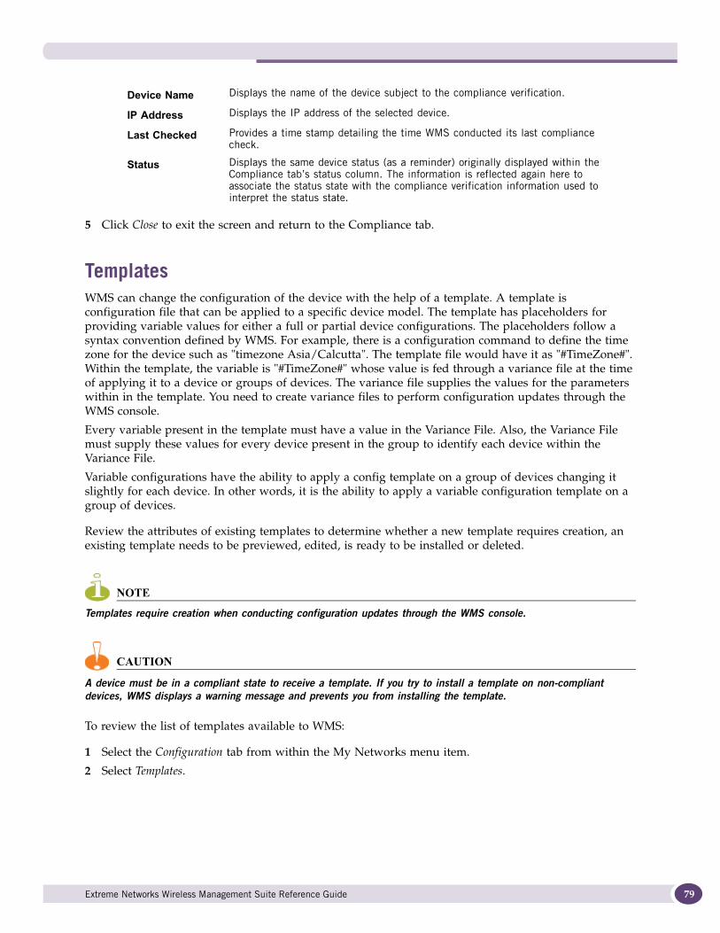
5 Click Close to exit the screen and return to the Compliance tab.
TemplatesWMS can change the configuration of the device with the help of a template. A template is configuration file that can be applied to a specific device model. The template has placeholders for providing variable values for either a full or partial device configurations. The placeholders follow a syntax convention defined by WMS. For example, there is a configuration command to define the time zone for the device such as "timezone Asia/Calcutta". The template file would have it as "#TimeZone#". Within the template, the variable is "#TimeZone#" whose value is fed through a variance file at the time of applying it to a device or groups of devices. The variance file supplies the values for the parameters within in the template. You need to create variance files to perform configuration updates through the WMS console.
Every variable present in the template must have a value in the Variance File. Also, the Variance File must supply these values for every device present in the group to identify each device within the Variance File.
Variable configurations have the ability to apply a config template on a group of devices changing it slightly for each device. In other words, it is the ability to apply a variable configuration template on a group of devices.
Review the attributes of existing templates to determine whether a new template requires creation, an existing template needs to be previewed, edited, is ready to be installed or deleted.
NOTE
Templates require creation when conducting configuration updates through the WMS console.
CAUTION
A device must be in a compliant state to receive a template. If you try to install a template on non-compliant devices, WMS displays a warning message and prevents you from installing the template.
To review the list of templates available to WMS:
1 Select the Configuration tab from within the My Networks menu item.
2 Select Templates.
Device Name Displays the name of the device subject to the compliance verification.
IP Address Displays the IP address of the selected device.
Last Checked Provides a time stamp detailing the time WMS conducted its last compliance check.
Status Displays the same device status (as a reminder) originally displayed within the Compliance tab’s status column. The information is reflected again here to associate the status state with the compliance verification information used to interpret the status state.
Extreme Networks Wireless Management Suite Reference Guide 79
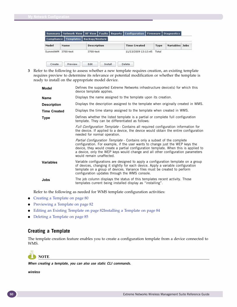
My Network Configuration
80
3 Refer to the following to assess whether a new template requires creation, an existing template requires preview to determine its relevance or potential modification or whether the template is ready to install on the appropriate model device.
Refer to the following as needed for WMS template configuration activities:
● Creating a Template on page 80
● Previewing a Template on page 82
● Editing an Existing Template on page 82Installing a Template on page 84
● Deleting a Template on page 85
Creating a TemplateThe template creation feature enables you to create a configuration template from a device connected to WMS.
NOTE
When creating a template, you can also use static CLI commands.
wireless
Model Defines the supported Extreme Networks infrastructure device(s) for which this device template applies.
Name Displays the name assigned to the template upon its creation.
Description Displays the description assigned to the template when originally created in WMS.
Time Created Displays the time stamp assigned to the template when created in WMS.
Type Defines whether the listed template is a partial or complete full configuration template. They can be differentiated as follows:
Full Configuration Template - Contains all required configuration information for the device. If applied to a device, the device would obtain the entire configuration needed for normal operation.
Partial Configuration Template - Contains only a subset of the complete configuration. For example, if the user wants to change just the WEP keys the device, they would create a partial configuration template. When this is applied to a device, only the WEP keys would change and all other configuration parameters would remain unaffected.
Variables Variable configurations are designed to apply a configuration template on a group of devices, changing it slightly for each device. Apply a variable configuration template on a group of devices. Variance files must be created to perform configuration updates through the WMS console.
Jobs The job column displays the status of this templates recent activity. Those templates current being installed display as “installing”.
Extreme Networks Wireless Management Suite Reference Guide
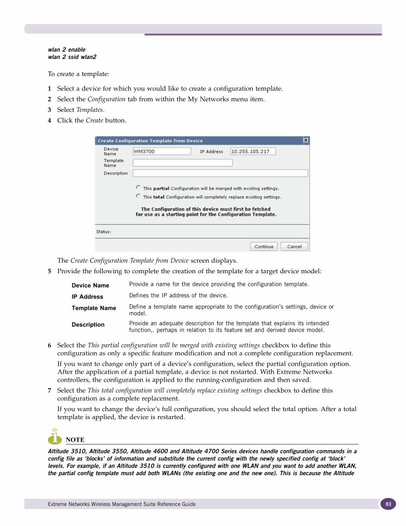
wlan 2 enable wlan 2 ssid wlan2
To create a template:
1 Select a device for which you would like to create a configuration template.
2 Select the Configuration tab from within the My Networks menu item.
3 Select Templates.
4 Click the Create button.
The Create Configuration Template from Device screen displays.
5 Provide the following to complete the creation of the template for a target device model:
6 Select the This partial configuration will be merged with existing settings checkbox to define this configuration as only a specific feature modification and not a complete configuration replacement.
If you want to change only part of a device’s configuration, select the partial configuration option. After the application of a partial template, a device is not restarted. With Extreme Networks controllers, the configuration is applied to the running-configuration and then saved.
7 Select the This total configuration will completely replace existing settings checkbox to define this configuration as a complete replacement.
If you want to change the device’s full configuration, you should select the total option. After a total template is applied, the device is restarted.
NOTE
Altitude 3510, Altitude 3550, Altitude 4600 and Altitude 4700 Series devices handle configuration commands in a config file as ‘blocks’ of information and substitute the current config with the newly specified config at ‘block’ levels. For example, if an Altitude 3510 is currently configured with one WLAN and you want to add another WLAN, the partial config template must add both WLANs (the existing one and the new one). This is because the Altitude
Device Name Provide a name for the device providing the configuration template.
IP Address Defines the IP address of the device.
Template Name Define a template name appropriate to the configuration’s settings, device or model.
Description Provide an adequate description for the template that explains its intended function,. perhaps in relation to its feature set and derived device model.
Extreme Networks Wireless Management Suite Reference Guide 81
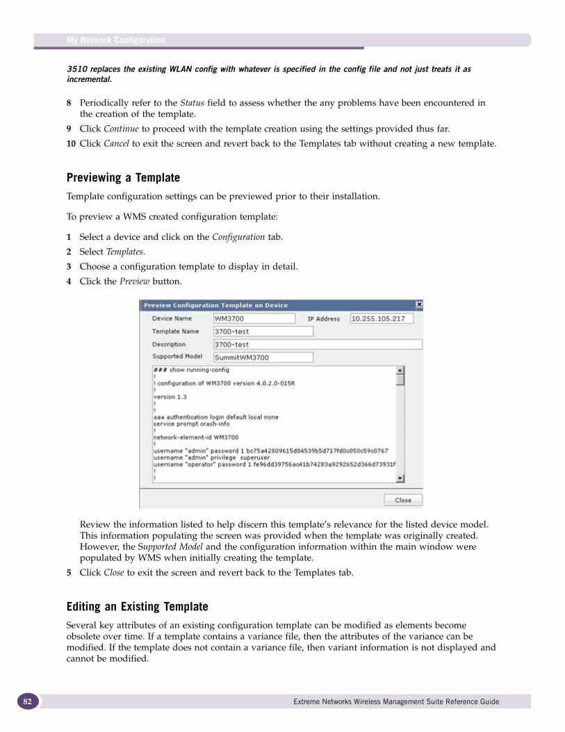
My Network Configuration
82
3510 replaces the existing WLAN config with whatever is specified in the config file and not just treats it as incremental.
8 Periodically refer to the Status field to assess whether the any problems have been encountered in the creation of the template.
9 Click Continue to proceed with the template creation using the settings provided thus far.
10 Click Cancel to exit the screen and revert back to the Templates tab without creating a new template.
Previewing a TemplateTemplate configuration settings can be previewed prior to their installation.
To preview a WMS created configuration template:
1 Select a device and click on the Configuration tab.
2 Select Templates.
3 Choose a configuration template to display in detail.
4 Click the Preview button.
Review the information listed to help discern this template’s relevance for the listed device model. This information populating the screen was provided when the template was originally created. However, the Supported Model and the configuration information within the main window were populated by WMS when initially creating the template.
5 Click Close to exit the screen and revert back to the Templates tab.
Editing an Existing TemplateSeveral key attributes of an existing configuration template can be modified as elements become obsolete over time. If a template contains a variance file, then the attributes of the variance can be modified. If the template does not contain a variance file, then variant information is not displayed and cannot be modified.
Extreme Networks Wireless Management Suite Reference Guide
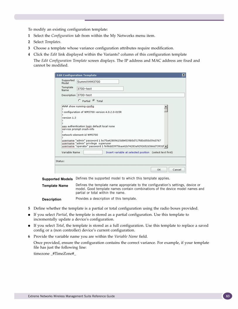
To modify an existing configuration template:
1 Select the Configuration tab from within the My Networks menu item.
2 Select Templates.
3 Choose a template whose variance configuration attributes require modification.
4 Click the Edit link displayed within the Variants? column of this configuration template
The Edit Configuration Template screen displays. The IP address and MAC address are fixed and cannot be modified.
5 Define whether the template is a partial or total configuration using the radio boxes provided.
● If you select Partial, the template is stored as a partial configuration. Use this template to incrementally update a device's configuration.
● If you select Total, the template is stored as a full configuration. Use this template to replace a saved config or a (non controller) device’s current configuration.
6 Provide the variable name you are within the Variable Name field.
Once provided, ensure the configuration contains the correct variance. For example, if your template file has just the following line:
timezone _#TimeZone#_
Supported Models Defines the supported model to which this template applies.
Template Name Defines the template name appropriate to the configuration’s settings, device or model. Good template names contain combinations of the device model names and partial or total within the name.
Description Provides a description of this template.
Extreme Networks Wireless Management Suite Reference Guide 83
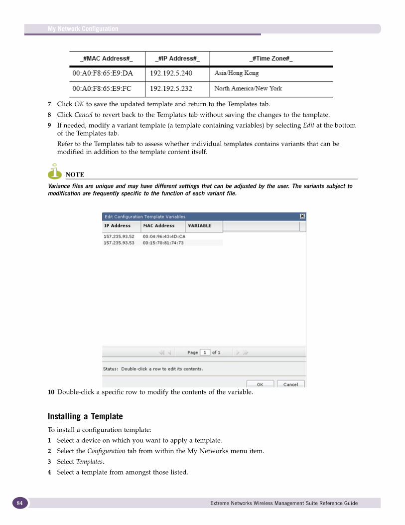
My Network Configuration
84
7 Click OK to save the updated template and return to the Templates tab.
8 Click Cancel to revert back to the Templates tab without saving the changes to the template.
9 If needed, modify a variant template (a template containing variables) by selecting Edit at the bottom of the Templates tab.
Refer to the Templates tab to assess whether individual templates contains variants that can be modified in addition to the template content itself.
NOTE
Variance files are unique and may have different settings that can be adjusted by the user. The variants subject to modification are frequently specific to the function of each variant file.
10 Double-click a specific row to modify the contents of the variable.
Installing a TemplateTo install a configuration template:
1 Select a device on which you want to apply a template.
2 Select the Configuration tab from within the My Networks menu item.
3 Select Templates.
4 Select a template from amongst those listed.
Extreme Networks Wireless Management Suite Reference Guide
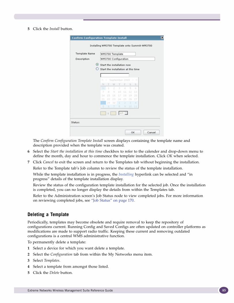
5 Click the Install button.
The Confirm Configuration Template Install screen displays containing the template name and description provided when the template was created.
6 Select the Start the installation at this time checkbox to refer to the calender and drop-down menu to define the month, day and hour to commence the template installation. Click OK when selected.
7 Click Cancel to exit the screen and return to the Templates tab without beginning the installation.
Refer to the Template tab’s Job column to review the status of the template installation.
While the template installation is in progress, the Installing hyperlink can be selected and “in progress” details of the template installation display.
Review the status of the configuration template installation for the selected job. Once the installation is completed, you can no longer display the details from within the Templates tab.
Refer to the Administration screen’s Job Status node to view completed jobs. For more information on reviewing completed jobs, see “Job Status” on page 170.
Deleting a TemplatePeriodically, templates may become obsolete and require removal to keep the repository of configurations current. Running Config and Saved Configs are often updated on controller platforms as modifications are made to support radio traffic. Keeping these current and removing outdated configurations is a central WMS administrative function.
To permanently delete a template:
1 Select a device for which you want delete a template.
2 Select the Configuration tab from within the My Networks menu item.
3 Select Templates.
4 Select a template from amongst those listed.
5 Click the Delete button.
Extreme Networks Wireless Management Suite Reference Guide 85
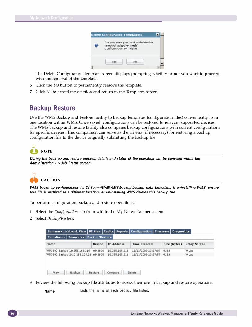
My Network Configuration
86
The Delete Configuration Template screen displays prompting whether or not you want to proceed with the removal of the template.
6 Click the Yes button to permanently remove the template.
7 Click No to cancel the deletion and return to the Templates screen.
Backup RestoreUse the WMS Backup and Restore facility to backup templates (configuration files) conveniently from one location within WMS. Once saved, configurations can be restored to relevant supported devices. The WMS backup and restore facility also compares backup configurations with current configurations for specific devices. This comparison can serve as the criteria (if necessary) for restoring a backup configuration file to the device originally submitting the backup file.
NOTE
During the back up and restore process, details and status of the operation can be reviewed within the Administration - > Job Status screen.
CAUTION
WMS backs up configurations to: C:\SummitWM\WMS\backup\backup_data_time.data. If uninstalling WMS, ensure this file is archived to a different location, as uninstalling WMS deletes this backup file.
To perform configuration backup and restore operations:
1 Select the Configuration tab from within the My Networks menu item.
2 Select Backup/Restore.
3 Review the following backup file attributes to assess their use in backup and restore operations:
Name Lists the name of each backup file listed.
Extreme Networks Wireless Management Suite Reference Guide
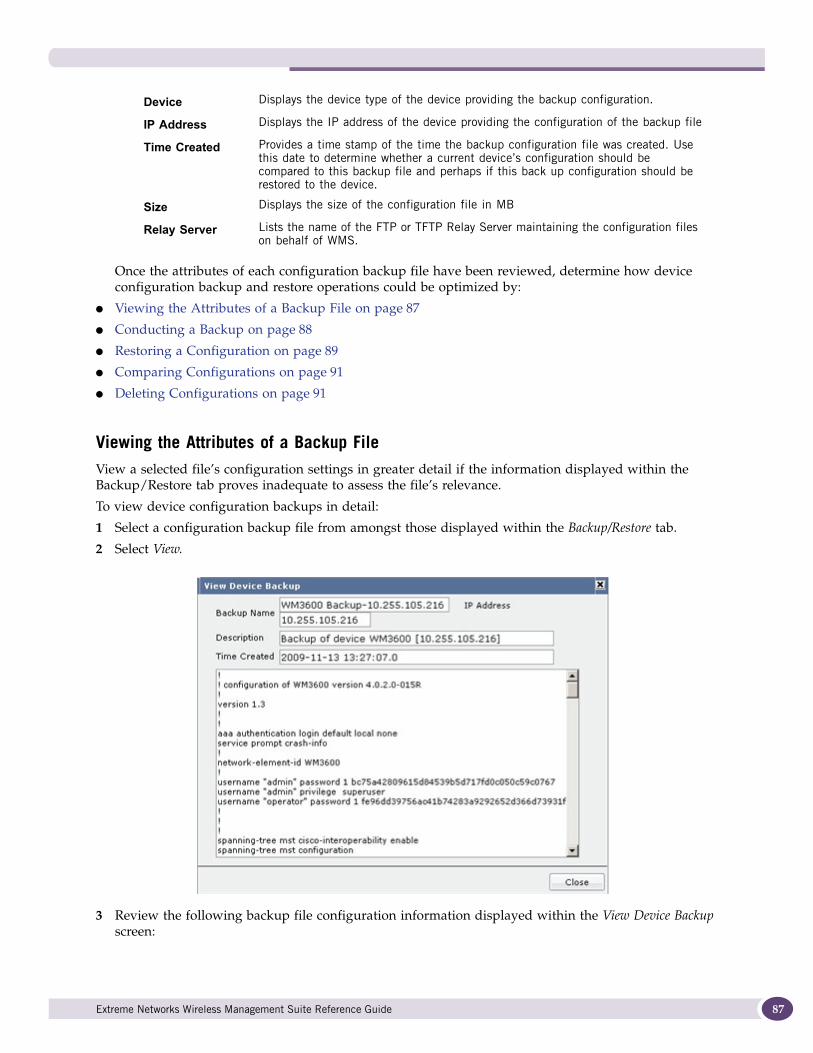
Once the attributes of each configuration backup file have been reviewed, determine how device configuration backup and restore operations could be optimized by:
● Viewing the Attributes of a Backup File on page 87
● Conducting a Backup on page 88
● Restoring a Configuration on page 89
● Comparing Configurations on page 91
● Deleting Configurations on page 91
Viewing the Attributes of a Backup FileView a selected file’s configuration settings in greater detail if the information displayed within the Backup/Restore tab proves inadequate to assess the file’s relevance.
To view device configuration backups in detail:
1 Select a configuration backup file from amongst those displayed within the Backup/Restore tab.
2 Select View.
3 Review the following backup file configuration information displayed within the View Device Backup screen:
Device Displays the device type of the device providing the backup configuration.
IP Address Displays the IP address of the device providing the configuration of the backup file
Time Created Provides a time stamp of the time the backup configuration file was created. Use this date to determine whether a current device’s configuration should be compared to this backup file and perhaps if this back up configuration should be restored to the device.
Size Displays the size of the configuration file in MB
Relay Server Lists the name of the FTP or TFTP Relay Server maintaining the configuration files on behalf of WMS.
Extreme Networks Wireless Management Suite Reference Guide 87
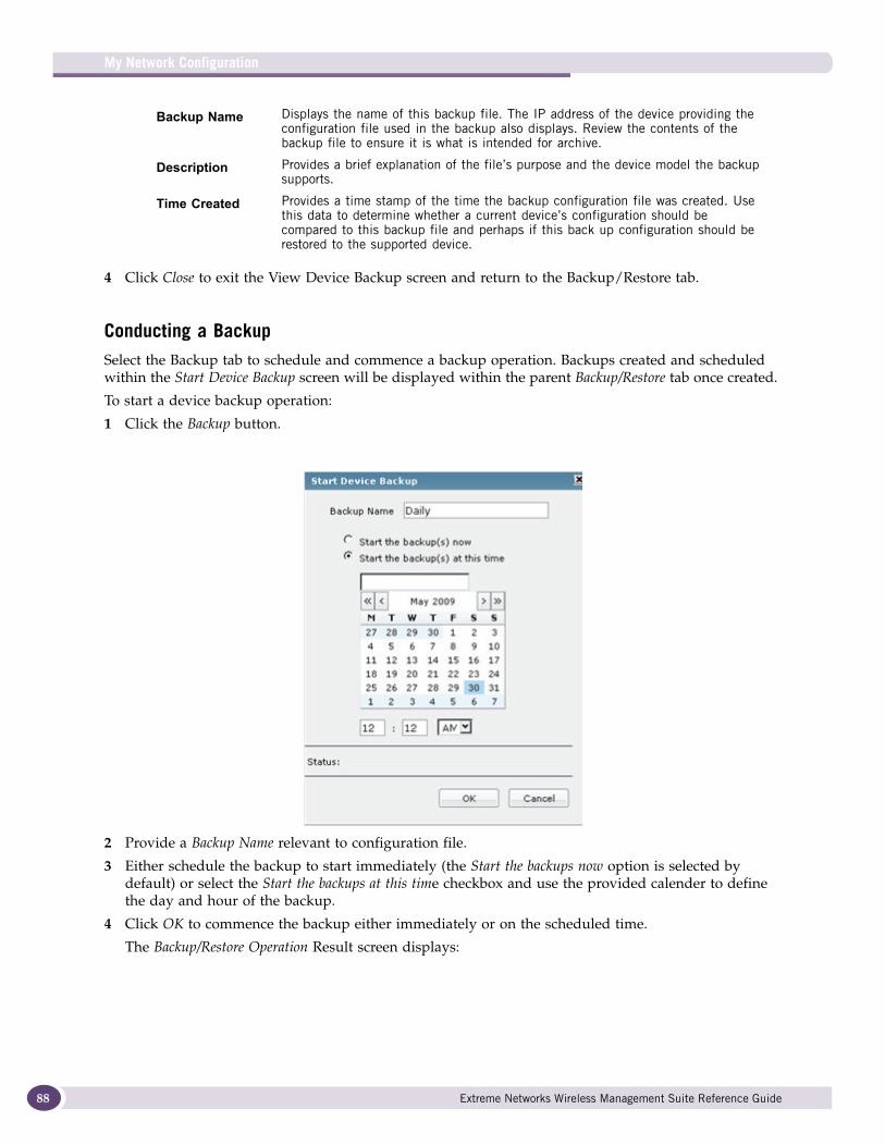
My Network Configuration
88
4 Click Close to exit the View Device Backup screen and return to the Backup/Restore tab.
Conducting a BackupSelect the Backup tab to schedule and commence a backup operation. Backups created and scheduled within the Start Device Backup screen will be displayed within the parent Backup/Restore tab once created.
To start a device backup operation:
1 Click the Backup button.
2 Provide a Backup Name relevant to configuration file.
3 Either schedule the backup to start immediately (the Start the backups now option is selected by default) or select the Start the backups at this time checkbox and use the provided calender to define the day and hour of the backup.
4 Click OK to commence the backup either immediately or on the scheduled time.
The Backup/Restore Operation Result screen displays:
Backup Name Displays the name of this backup file. The IP address of the device providing the configuration file used in the backup also displays. Review the contents of the backup file to ensure it is what is intended for archive.
Description Provides a brief explanation of the file’s purpose and the device model the backup supports.
Time Created Provides a time stamp of the time the backup configuration file was created. Use this data to determine whether a current device’s configuration should be compared to this backup file and perhaps if this back up configuration should be restored to the supported device.
Extreme Networks Wireless Management Suite Reference Guide
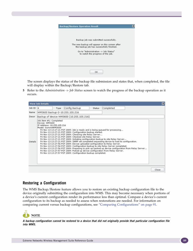
The screen displays the status of the backup file submission and states that, when completed, the file will display within the Backup/Restore tab.
5 Refer to the Administration -> Job Status screen to watch the progress of the backup operation as it occurs.
Restoring a ConfigurationThe WMS Backup/Restore feature allows you to restore an existing backup configuration file to the device originally submitting the configuration into WMS. This may become necessary when portions of a device’s current configuration render its performance less than optimal. Compare a device’s current configuration to its backup as needed to assess when restorations are needed. For information on comparing current versus backup configurations, see “Comparing Configurations” on page 91.
NOTE
A backup configuration cannot be restored to a device that did not originally provide that particular configuration file into WMS.
Extreme Networks Wireless Management Suite Reference Guide 89
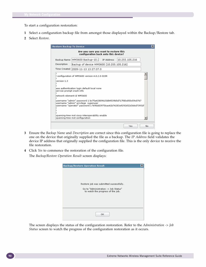
My Network Configuration
90
To start a configuration restoration:
1 Select a configuration backup file from amongst those displayed within the Backup/Restore tab.
2 Select Restore.
3 Ensure the Backup Name and Description are correct since this configuration file is going to replace the one on the device that originally supplied the file as a backup. The IP Address field validates the device IP address that originally supplied the configuration file. This is the only device to receive the file restoration.
4 Click Yes to commence the restoration of the configuration file.
The Backup/Restore Operation Result screen displays:
The screen displays the status of the configuration restoration. Refer to the Administration -> Job Status screen to watch the progress of the configuration restoration as it occurs.
Extreme Networks Wireless Management Suite Reference Guide
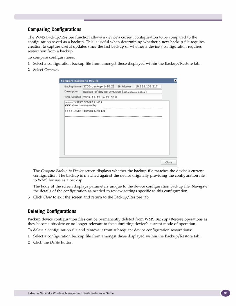
Comparing ConfigurationsThe WMS Backup/Restore function allows a device’s current configuration to be compared to the configuration saved as a backup. This is useful when determining whether a new backup file requires creation to capture useful updates since the last backup or whether a device’s configuration requires restoration from a backup.
To compare configurations:
1 Select a configuration backup file from amongst those displayed within the Backup/Restore tab.
2 Select Compare.
The Compare Backup to Device screen displays whether the backup file matches the device’s current configuration. The backup is matched against the device originally providing the configuration file to WMS for use as a backup.
The body of the screen displays parameters unique to the device configuration backup file. Navigate the details of the configuration as needed to review settings specific to this configuration.
3 Click Close to exit the screen and return to the Backup/Restore tab.
Deleting ConfigurationsBackup device configuration files can be permanently deleted from WMS Backup/Restore operations as they become obsolete or no longer relevant to the submitting device’s current mode of operation.
To delete a configuration file and remove it from subsequent device configuration restorations:
1 Select a configuration backup file from amongst those displayed within the Backup/Restore tab.
2 Click the Delete button.
Extreme Networks Wireless Management Suite Reference Guide 91
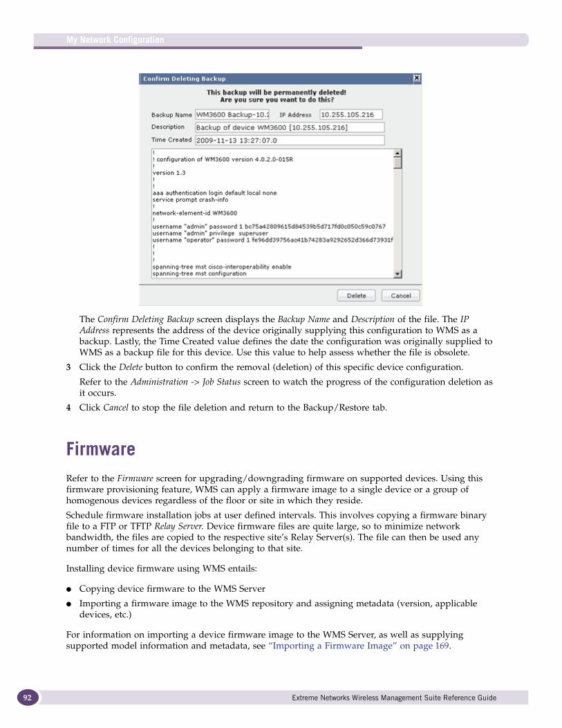
My Network Configuration
92
The Confirm Deleting Backup screen displays the Backup Name and Description of the file. The IP Address represents the address of the device originally supplying this configuration to WMS as a backup. Lastly, the Time Created value defines the date the configuration was originally supplied to WMS as a backup file for this device. Use this value to help assess whether the file is obsolete.
3 Click the Delete button to confirm the removal (deletion) of this specific device configuration.
Refer to the Administration -> Job Status screen to watch the progress of the configuration deletion as it occurs.
4 Click Cancel to stop the file deletion and return to the Backup/Restore tab.
FirmwareRefer to the Firmware screen for upgrading/downgrading firmware on supported devices. Using this firmware provisioning feature, WMS can apply a firmware image to a single device or a group of homogenous devices regardless of the floor or site in which they reside.
Schedule firmware installation jobs at user defined intervals. This involves copying a firmware binary file to a FTP or TFTP Relay Server. Device firmware files are quite large, so to minimize network bandwidth, the files are copied to the respective site’s Relay Server(s). The file can then be used any number of times for all the devices belonging to that site.
Installing device firmware using WMS entails:
● Copying device firmware to the WMS Server
● Importing a firmware image to the WMS repository and assigning metadata (version, applicable devices, etc.)
For information on importing a device firmware image to the WMS Server, as well as supplying supported model information and metadata, see “Importing a Firmware Image” on page 169.
Extreme Networks Wireless Management Suite Reference Guide
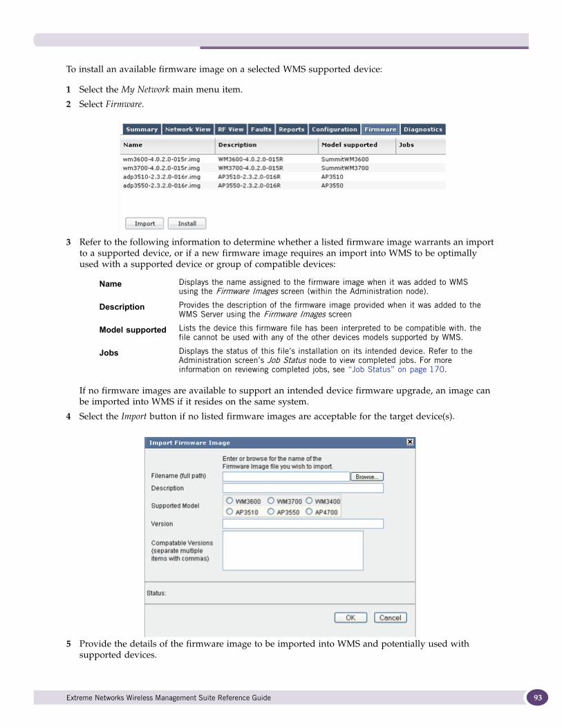
To install an available firmware image on a selected WMS supported device:
1 Select the My Network main menu item.
2 Select Firmware.
3 Refer to the following information to determine whether a listed firmware image warrants an import to a supported device, or if a new firmware image requires an import into WMS to be optimally used with a supported device or group of compatible devices:
If no firmware images are available to support an intended device firmware upgrade, an image can be imported into WMS if it resides on the same system.
4 Select the Import button if no listed firmware images are acceptable for the target device(s).
5 Provide the details of the firmware image to be imported into WMS and potentially used with supported devices.
Name Displays the name assigned to the firmware image when it was added to WMS using the Firmware Images screen (within the Administration node).
Description Provides the description of the firmware image provided when it was added to the WMS Server using the Firmware Images screen
Model supported Lists the device this firmware file has been interpreted to be compatible with. the file cannot be used with any of the other devices models supported by WMS.
Jobs Displays the status of this file’s installation on its intended device. Refer to the Administration screen’s Job Status node to view completed jobs. For more information on reviewing completed jobs, see “Job Status” on page 170.
Extreme Networks Wireless Management Suite Reference Guide 93
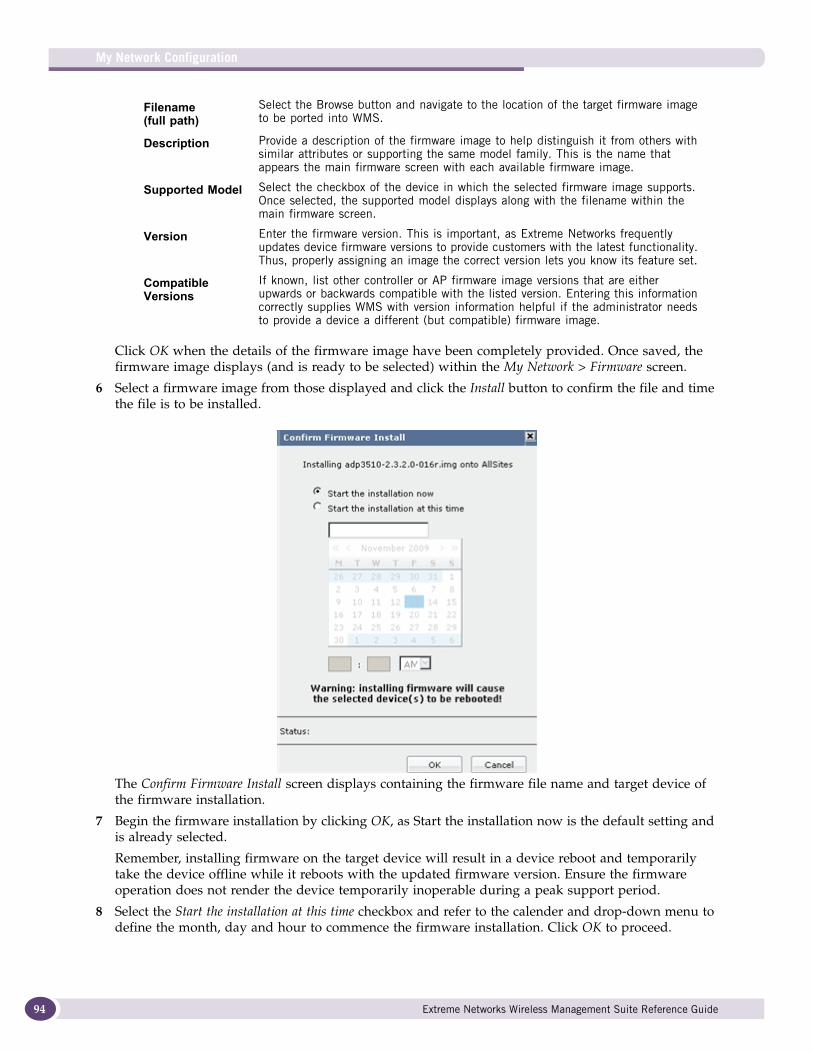
My Network Configuration
94
Click OK when the details of the firmware image have been completely provided. Once saved, the firmware image displays (and is ready to be selected) within the My Network > Firmware screen.
6 Select a firmware image from those displayed and click the Install button to confirm the file and time the file is to be installed.
The Confirm Firmware Install screen displays containing the firmware file name and target device of the firmware installation.
7 Begin the firmware installation by clicking OK, as Start the installation now is the default setting and is already selected.
Remember, installing firmware on the target device will result in a device reboot and temporarily take the device offline while it reboots with the updated firmware version. Ensure the firmware operation does not render the device temporarily inoperable during a peak support period.
8 Select the Start the installation at this time checkbox and refer to the calender and drop-down menu to define the month, day and hour to commence the firmware installation. Click OK to proceed.
Filename (full path)
Select the Browse button and navigate to the location of the target firmware image to be ported into WMS.
Description Provide a description of the firmware image to help distinguish it from others with similar attributes or supporting the same model family. This is the name that appears the main firmware screen with each available firmware image.
Supported Model Select the checkbox of the device in which the selected firmware image supports. Once selected, the supported model displays along with the filename within the main firmware screen.
Version Enter the firmware version. This is important, as Extreme Networks frequently updates device firmware versions to provide customers with the latest functionality. Thus, properly assigning an image the correct version lets you know its feature set.
Compatible Versions
If known, list other controller or AP firmware image versions that are either upwards or backwards compatible with the listed version. Entering this information correctly supplies WMS with version information helpful if the administrator needs to provide a device a different (but compatible) firmware image.
Extreme Networks Wireless Management Suite Reference Guide
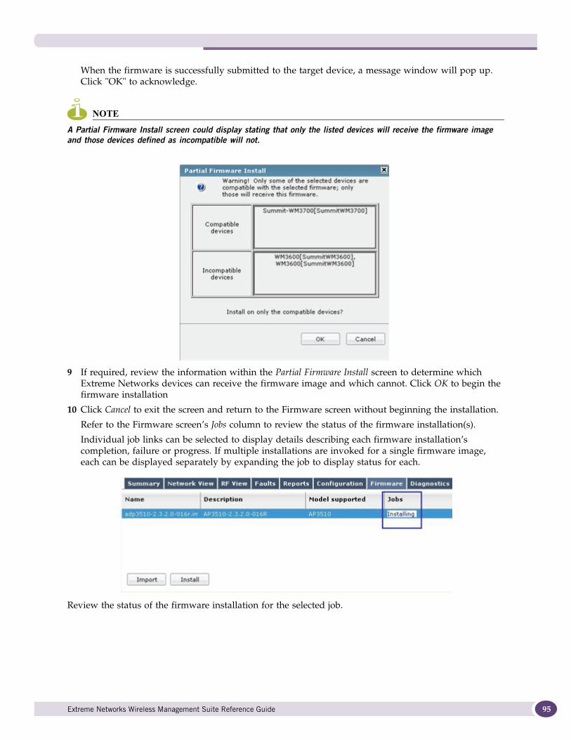
When the firmware is successfully submitted to the target device, a message window will pop up. Click "OK" to acknowledge.
NOTE
A Partial Firmware Install screen could display stating that only the listed devices will receive the firmware image and those devices defined as incompatible will not.
9 If required, review the information within the Partial Firmware Install screen to determine which Extreme Networks devices can receive the firmware image and which cannot. Click OK to begin the firmware installation
10 Click Cancel to exit the screen and return to the Firmware screen without beginning the installation.
Refer to the Firmware screen’s Jobs column to review the status of the firmware installation(s).
Individual job links can be selected to display details describing each firmware installation’s completion, failure or progress. If multiple installations are invoked for a single firmware image, each can be displayed separately by expanding the job to display status for each.
Review the status of the firmware installation for the selected job.
Extreme Networks Wireless Management Suite Reference Guide 95
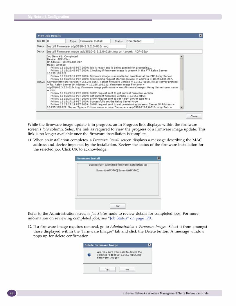
My Network Configuration
96
While the firmware image update is in progress, an In Progress link displays within the firmware screen’s Jobs column. Select the link as required to view the progress of a firmware image update. This link is no longer available once the firmware installation is complete.
11 When an installation completes, a Firmware Install screen displays a message describing the MAC address and device impacted by the installation. Review the status of the firmware installation for the selected job. Click OK to acknowledge.
Refer to the Administration screen’s Job Status node to review details for completed jobs. For more information on reviewing completed jobs, see “Job Status” on page 170.
12 If a firmware image requires removal, go to Administration > Firmware Images. Select it from amongst those displayed within the "Firmware Images" tab and click the Delete button. A message window pops up for delete confirmation.
Extreme Networks Wireless Management Suite Reference Guide
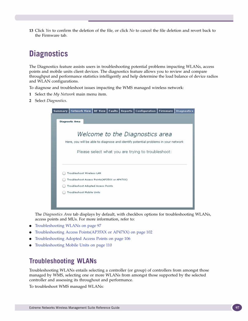
13 Click Yes to confirm the deletion of the file, or click No to cancel the file deletion and revert back to the Firmware tab.
DiagnosticsThe Diagnostics feature assists users in troubleshooting potential problems impacting WLANs, access points and mobile units client devices. The diagnostics feature allows you to review and compare throughput and performance statistics intelligently and help determine the load balance of device radios and WLAN configurations.
To diagnose and troubleshoot issues impacting the WMS managed wireless network:
1 Select the My Network main menu item.
2 Select Diagnostics.
The Diagnostics Area tab displays by default, with checkbox options for troubleshooting WLANs, access points and MUs. For more information, refer to:
● Troubleshooting WLANs on page 97
● Troubleshooting Access Points(AP35XX or AP47XX) on page 102
● Troubleshooting Adopted Access Points on page 106
● Troubleshooting Mobile Units on page 110
Troubleshooting WLANsTroubleshooting WLANs entails selecting a controller (or group) of controllers from amongst those managed by WMS, selecting one or more WLANs from amongst those supported by the selected controller and assessing its throughout and performance.
To troubleshoot WMS managed WLANs:
Extreme Networks Wireless Management Suite Reference Guide 97
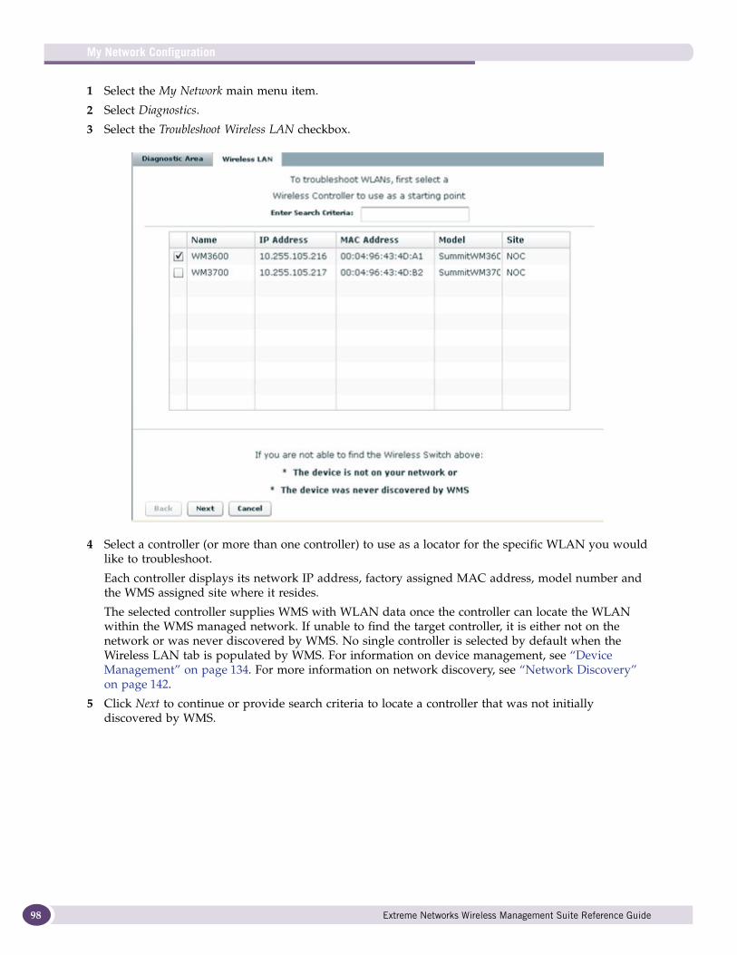
My Network Configuration
98
1 Select the My Network main menu item.
2 Select Diagnostics.
3 Select the Troubleshoot Wireless LAN checkbox.
4 Select a controller (or more than one controller) to use as a locator for the specific WLAN you would like to troubleshoot.
Each controller displays its network IP address, factory assigned MAC address, model number and the WMS assigned site where it resides.
The selected controller supplies WMS with WLAN data once the controller can locate the WLAN within the WMS managed network. If unable to find the target controller, it is either not on the network or was never discovered by WMS. No single controller is selected by default when the Wireless LAN tab is populated by WMS. For information on device management, see “Device Management” on page 134. For more information on network discovery, see “Network Discovery” on page 142.
5 Click Next to continue or provide search criteria to locate a controller that was not initially discovered by WMS.
Extreme Networks Wireless Management Suite Reference Guide
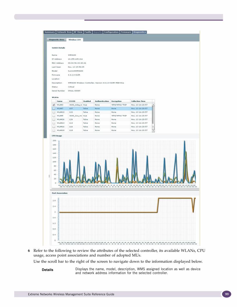
6 Refer to the following to review the attributes of the selected controller, its available WLANs, CPU usage, access point associations and number of adopted MUs.
Use the scroll bar to the right of the screen to navigate down to the information displayed below.
Details Displays the name, model, description, WMS assigned location as well as device and network address information for the selected controller.
Extreme Networks Wireless Management Suite Reference Guide 99

My Network Configuration
100
7 Select a WLAN from those available (for the selected controller) and click Next to display a set of performance information specific to the selected WLAN and its hosting wireless controller.
WLANs Displays each WLAN available to the reporting controller. Each WLAN displays by name, ESSID its enabled/disabled state and collection time when data was last reported to WMS. Select the checkbox option to the left of a WLAN (or group of WLANs) to display a set of WLAN performance details specific to that WLAN. This step is where the performance troubleshooting of specific WLANs can best be assessed.
CPU Usage Displays controller CPU consumption values over the time. Select a point in the graph directly above one of the listed trend periods to display the CPU load and a time stamp of when the value was computed by WMS.
Access Point Association
Displays the number of associated access points on the selected controller. Select a point in the graph directly above one of the listed trend periods to display a count of associated devices and a time stamp of when the value was computed by WMS.
Number of MUs Adopted
Each radio adopted by the selected controller can display its number of associated MUs over the timeline listed at the bottom of the screen. Select a point in the graph directly above one of the listed trend periods to display the number of MU associated to each radio and a time stamp of when the value was computed by WMS.
Extreme Networks Wireless Management Suite Reference Guide
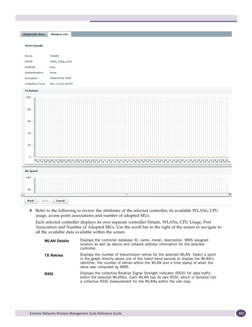
8 Refer to the following to review the attributes of the selected controller, its available WLANs, CPU usage, access point associations and number of adopted MUs.
Each selected controller displays its own separate controller Details, WLANs, CPU Usage, Port Association and Number of Adopted MUs. Use the scroll bar to the right of the screen to navigate to all the available data available within the screen.
WLAN Details Displays the controller database ID, name, model, description, WMS assigned location as well as device and network address information for the selected controller.
TX Retries Displays the number of transmission retries for the selected WLAN. Select a point in the graph directly above one of the listed trend periods to display the WLAN’s identifier, the number of retries within the WLAN and a time stamp of when the value was computed by WMS.
RSSI Displays the collective Relative Signal Strength Indicator (RSSI) for data traffic within the selected WLAN(s). Each WLAN has its own RSSI, which is factored into a collective RSSI measurement for the WLANs within the site map.
Extreme Networks Wireless Management Suite Reference Guide 101
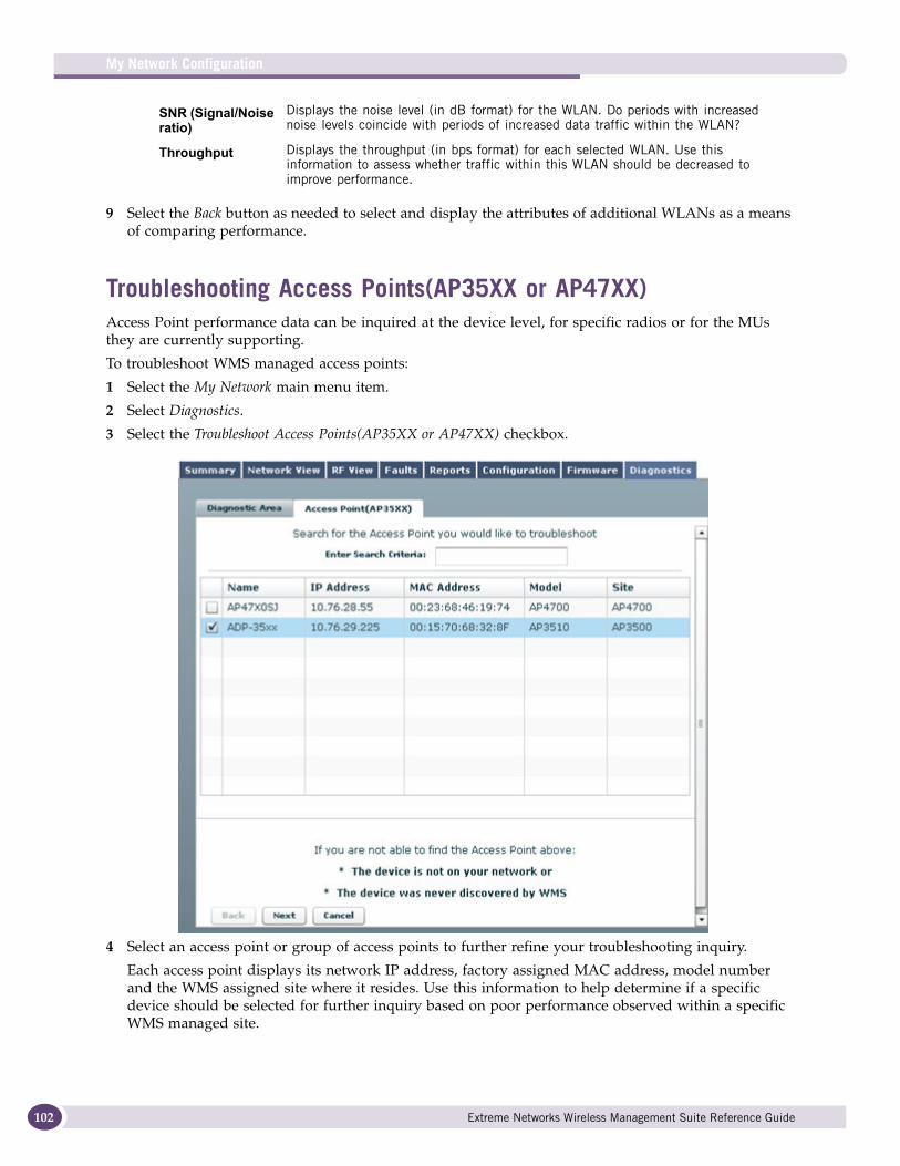
My Network Configuration
102
9 Select the Back button as needed to select and display the attributes of additional WLANs as a means of comparing performance.
Troubleshooting Access Points(AP35XX or AP47XX)Access Point performance data can be inquired at the device level, for specific radios or for the MUs they are currently supporting.
To troubleshoot WMS managed access points:
1 Select the My Network main menu item.
2 Select Diagnostics.
3 Select the Troubleshoot Access Points(AP35XX or AP47XX) checkbox.
4 Select an access point or group of access points to further refine your troubleshooting inquiry.
Each access point displays its network IP address, factory assigned MAC address, model number and the WMS assigned site where it resides. Use this information to help determine if a specific device should be selected for further inquiry based on poor performance observed within a specific WMS managed site.
SNR (Signal/Noise ratio)
Displays the noise level (in dB format) for the WLAN. Do periods with increased noise levels coincide with periods of increased data traffic within the WLAN?
Throughput Displays the throughput (in bps format) for each selected WLAN. Use this information to assess whether traffic within this WLAN should be decreased to improve performance.
Extreme Networks Wireless Management Suite Reference Guide
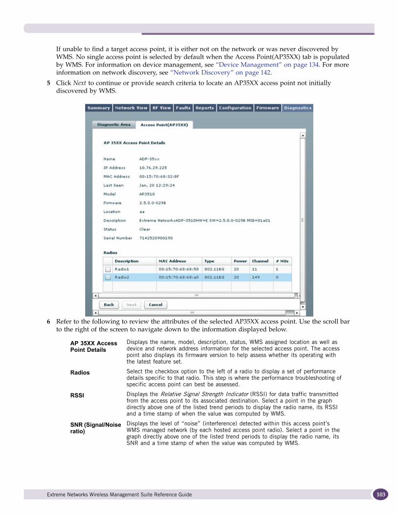
If unable to find a target access point, it is either not on the network or was never discovered by WMS. No single access point is selected by default when the Access Point(AP35XX) tab is populated by WMS. For information on device management, see “Device Management” on page 134. For more information on network discovery, see “Network Discovery” on page 142.
5 Click Next to continue or provide search criteria to locate an AP35XX access point not initially discovered by WMS.
6 Refer to the following to review the attributes of the selected AP35XX access point. Use the scroll bar to the right of the screen to navigate down to the information displayed below.
AP 35XX Access Point Details
Displays the name, model, description, status, WMS assigned location as well as device and network address information for the selected access point. The access point also displays its firmware version to help assess whether its operating with the latest feature set.
Radios Select the checkbox option to the left of a radio to display a set of performance details specific to that radio. This step is where the performance troubleshooting of specific access point can best be assessed.
RSSI Displays the Relative Signal Strength Indicator (RSSI) for data traffic transmitted from the access point to its associated destination. Select a point in the graph directly above one of the listed trend periods to display the radio name, its RSSI and a time stamp of when the value was computed by WMS.
SNR (Signal/Noise ratio)
Displays the level of “noise” (interference) detected within this access point’s WMS managed network (by each hosted access point radio). Select a point in the graph directly above one of the listed trend periods to display the radio name, its SNR and a time stamp of when the value was computed by WMS.
Extreme Networks Wireless Management Suite Reference Guide 103
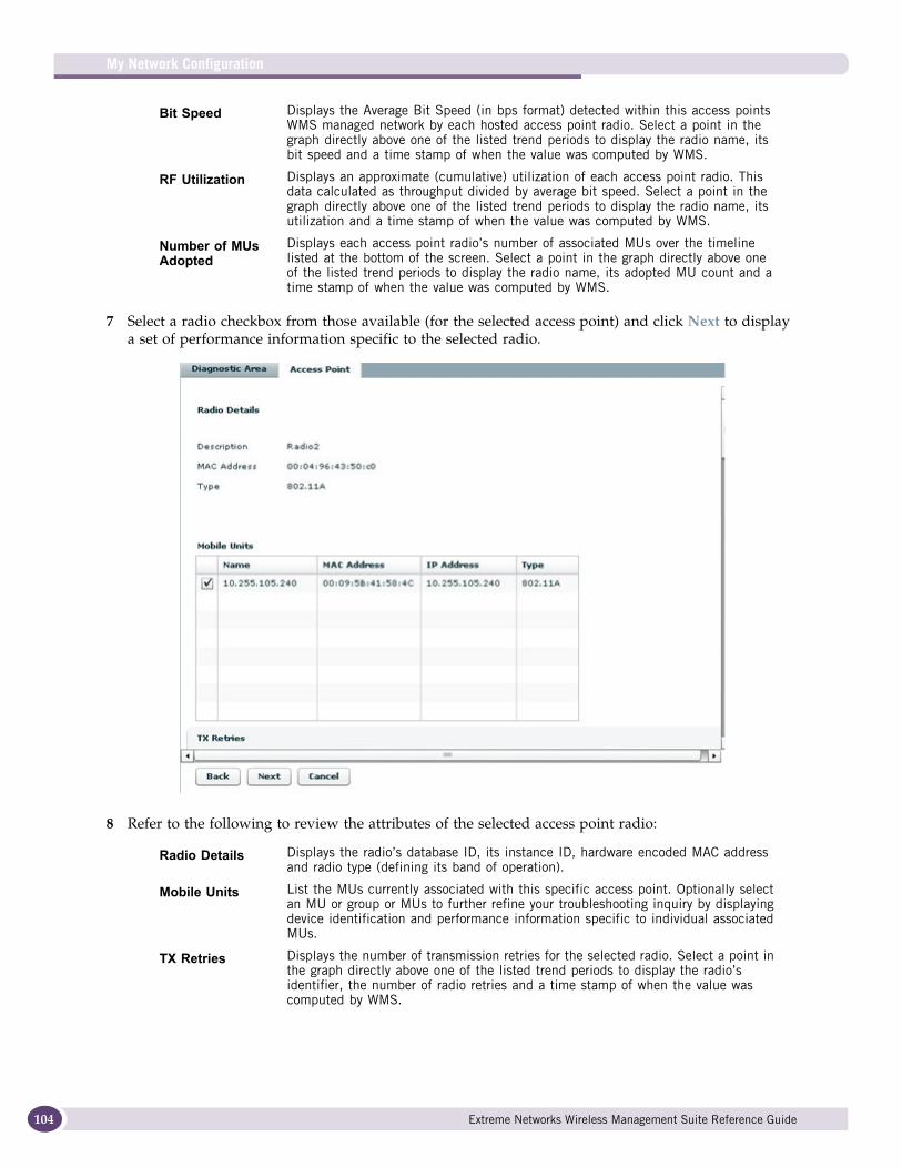
My Network Configuration
104
7 Select a radio checkbox from those available (for the selected access point) and click Next to display a set of performance information specific to the selected radio.
8 Refer to the following to review the attributes of the selected access point radio:
Bit Speed Displays the Average Bit Speed (in bps format) detected within this access points WMS managed network by each hosted access point radio. Select a point in the graph directly above one of the listed trend periods to display the radio name, its bit speed and a time stamp of when the value was computed by WMS.
RF Utilization Displays an approximate (cumulative) utilization of each access point radio. This data calculated as throughput divided by average bit speed. Select a point in the graph directly above one of the listed trend periods to display the radio name, its utilization and a time stamp of when the value was computed by WMS.
Number of MUs Adopted
Displays each access point radio’s number of associated MUs over the timeline listed at the bottom of the screen. Select a point in the graph directly above one of the listed trend periods to display the radio name, its adopted MU count and a time stamp of when the value was computed by WMS.
Radio Details Displays the radio’s database ID, its instance ID, hardware encoded MAC address and radio type (defining its band of operation).
Mobile Units List the MUs currently associated with this specific access point. Optionally select an MU or group or MUs to further refine your troubleshooting inquiry by displaying device identification and performance information specific to individual associated MUs.
TX Retries Displays the number of transmission retries for the selected radio. Select a point in the graph directly above one of the listed trend periods to display the radio’s identifier, the number of radio retries and a time stamp of when the value was computed by WMS.
Extreme Networks Wireless Management Suite Reference Guide
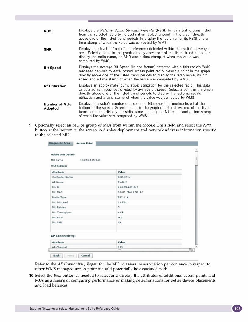
9 Optionally select an MU or group of MUs from within the Mobile Units field and select the Next button at the bottom of the screen to display deployment and network address information specific to the selected MU.
Refer to the AP Connectivity Report for the MU to assess its association performance in respect to other WMS managed access point it could potentially be associated with.
10 Select the Back button as needed to select and display the attributes of additional access points and MUs as a means of comparing performance or making determinations for better device placements and load balances.
RSSI Displays the Relative Signal Strength Indicator (RSSI) for data traffic transmitted from the selected radio to its destination. Select a point in the graph directly above one of the listed trend periods to display the radio name, its RSSI and a time stamp of when the value was computed by WMS.
SNR Displays the level of “noise” (interference) detected within this radio’s coverage area. Select a point in the graph directly above one of the listed trend periods to display the radio name, its SNR and a time stamp of when the value was computed by WMS.
Bit Speed Displays the Average Bit Speed (in bps format) detected within this radio’s WMS managed network by each hosted access point radio. Select a point in the graph directly above one of the listed trend periods to display the radio name, its bit speed and a time stamp of when the value was computed by WMS.
Rf Utilization Displays an approximate (cumulative) utilization for the selected radio. This data calculated as throughput divided by average bit speed. Select a point in the graph directly above one of the listed trend periods to display the radio name, its utilization and a time stamp of when the value was computed by WMS.
Number of MUs Adopted
Displays the radio’s number of associated MUs over the timeline listed at the bottom of the screen. Select a point in the graph directly above one of the listed trend periods to display the radio name, its adopted MU count and a time stamp of when the value was computed by WMS.
Extreme Networks Wireless Management Suite Reference Guide 105
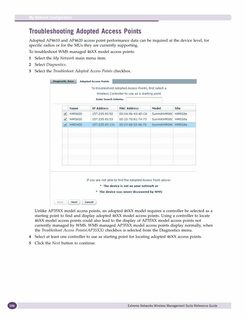
My Network Configuration
106
Troubleshooting Adopted Access PointsAdopted AP4610 and AP4620 access point performance data can be inquired at the device level, for specific radios or for the MUs they are currently supporting.
To troubleshoot WMS managed 46XX model access points:
1 Select the My Network main menu item.
2 Select Diagnostics.
3 Select the Troubleshoot Adopted Access Points checkbox.
Unlike AP35XX model access points, an adopted 46XX model requires a controller be selected as a starting point to find and display adopted 46XX model access points. Using a controller to locate 46XX model access points could also lead to the display of AP35XX model access points not currently managed by WMS. WMS managed AP35XX model access points display normally, when the Troubleshoot Access Points(AP35XX) checkbox is selected from the Diagnostics menu.
4 Select at least one controller to use as starting point for locating adopted 46XX access points.
5 Click the Next button to continue.
Extreme Networks Wireless Management Suite Reference Guide
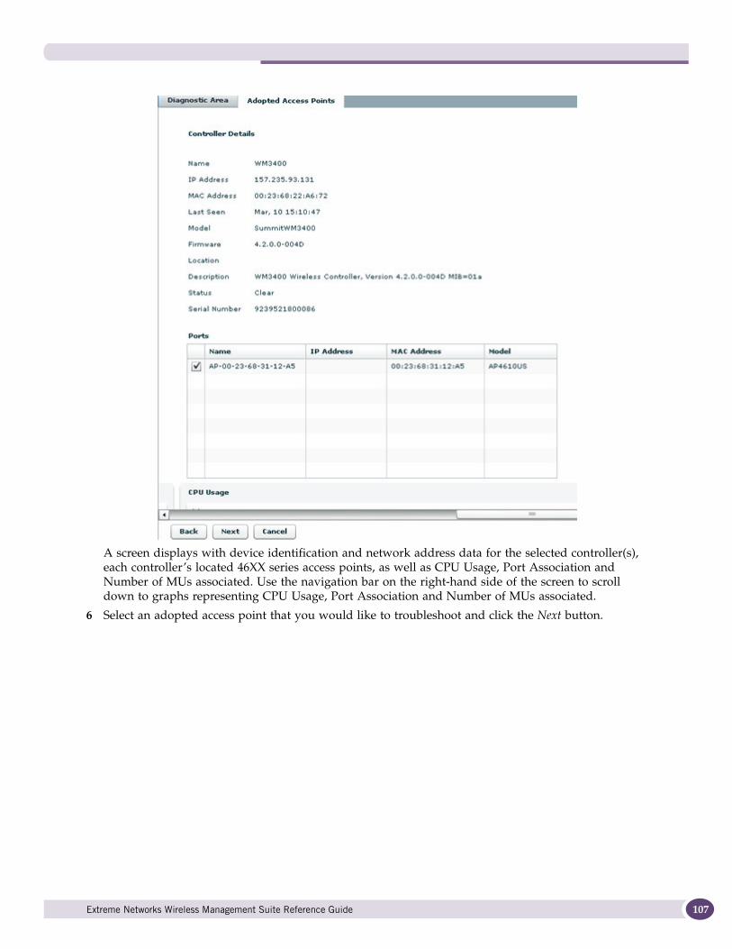
A screen displays with device identification and network address data for the selected controller(s), each controller’s located 46XX series access points, as well as CPU Usage, Port Association and Number of MUs associated. Use the navigation bar on the right-hand side of the screen to scroll down to graphs representing CPU Usage, Port Association and Number of MUs associated.
6 Select an adopted access point that you would like to troubleshoot and click the Next button.
Extreme Networks Wireless Management Suite Reference Guide 107
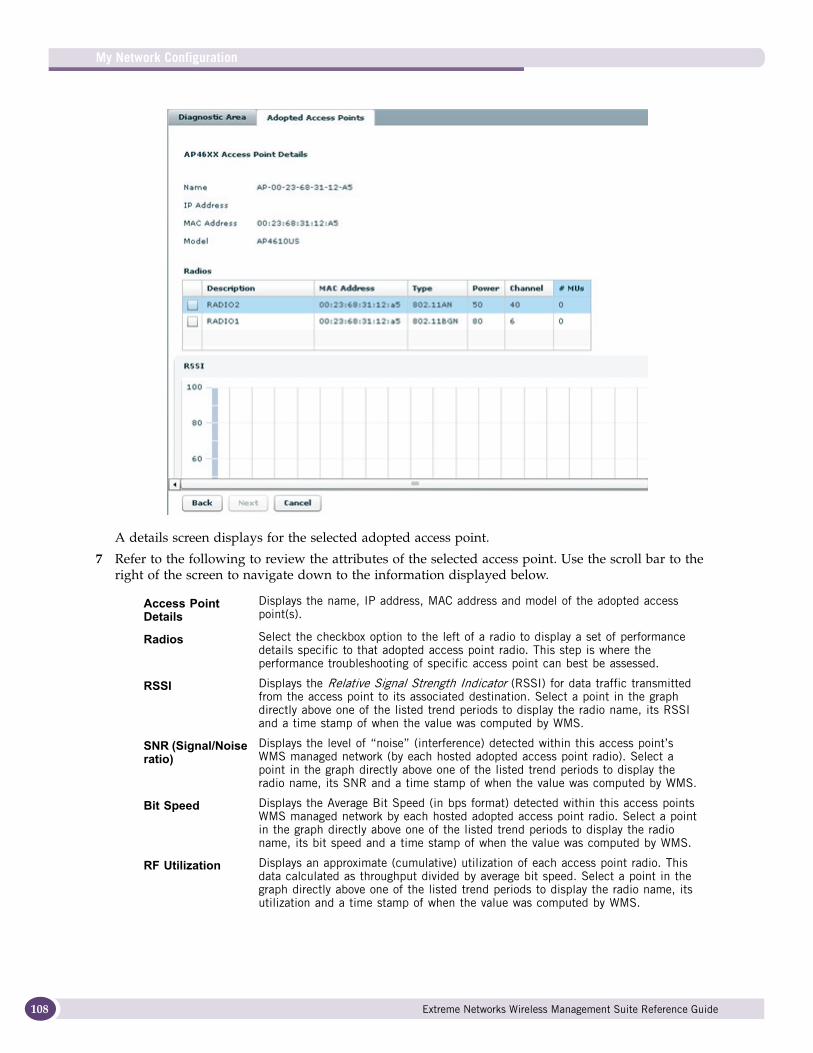
My Network Configuration
108
A details screen displays for the selected adopted access point.
7 Refer to the following to review the attributes of the selected access point. Use the scroll bar to the right of the screen to navigate down to the information displayed below.
Access Point Details
Displays the name, IP address, MAC address and model of the adopted access point(s).
Radios Select the checkbox option to the left of a radio to display a set of performance details specific to that adopted access point radio. This step is where the performance troubleshooting of specific access point can best be assessed.
RSSI Displays the Relative Signal Strength Indicator (RSSI) for data traffic transmitted from the access point to its associated destination. Select a point in the graph directly above one of the listed trend periods to display the radio name, its RSSI and a time stamp of when the value was computed by WMS.
SNR (Signal/Noise ratio)
Displays the level of “noise” (interference) detected within this access point’s WMS managed network (by each hosted adopted access point radio). Select a point in the graph directly above one of the listed trend periods to display the radio name, its SNR and a time stamp of when the value was computed by WMS.
Bit Speed Displays the Average Bit Speed (in bps format) detected within this access points WMS managed network by each hosted adopted access point radio. Select a point in the graph directly above one of the listed trend periods to display the radio name, its bit speed and a time stamp of when the value was computed by WMS.
RF Utilization Displays an approximate (cumulative) utilization of each access point radio. This data calculated as throughput divided by average bit speed. Select a point in the graph directly above one of the listed trend periods to display the radio name, its utilization and a time stamp of when the value was computed by WMS.
Extreme Networks Wireless Management Suite Reference Guide
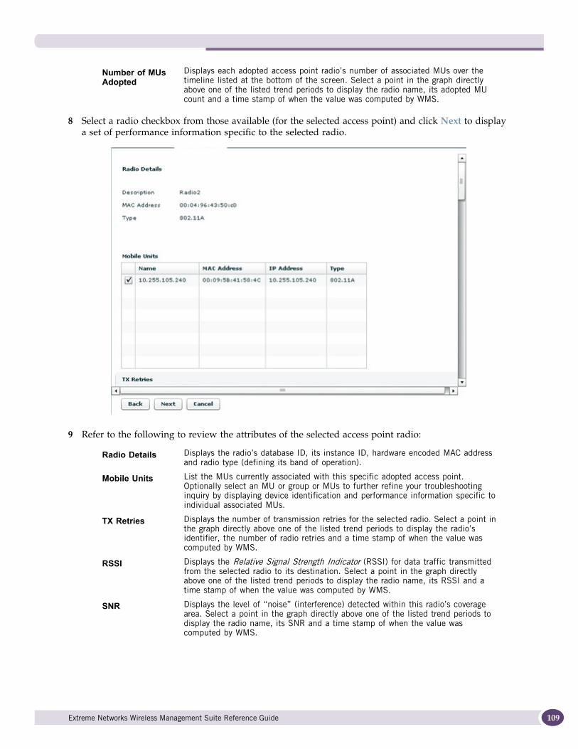
8 Select a radio checkbox from those available (for the selected access point) and click Next to display a set of performance information specific to the selected radio.
9 Refer to the following to review the attributes of the selected access point radio:
Number of MUs Adopted
Displays each adopted access point radio’s number of associated MUs over the timeline listed at the bottom of the screen. Select a point in the graph directly above one of the listed trend periods to display the radio name, its adopted MU count and a time stamp of when the value was computed by WMS.
Radio Details Displays the radio’s database ID, its instance ID, hardware encoded MAC address and radio type (defining its band of operation).
Mobile Units List the MUs currently associated with this specific adopted access point. Optionally select an MU or group or MUs to further refine your troubleshooting inquiry by displaying device identification and performance information specific to individual associated MUs.
TX Retries Displays the number of transmission retries for the selected radio. Select a point in the graph directly above one of the listed trend periods to display the radio’s identifier, the number of radio retries and a time stamp of when the value was computed by WMS.
RSSI Displays the Relative Signal Strength Indicator (RSSI) for data traffic transmitted from the selected radio to its destination. Select a point in the graph directly above one of the listed trend periods to display the radio name, its RSSI and a time stamp of when the value was computed by WMS.
SNR Displays the level of “noise” (interference) detected within this radio’s coverage area. Select a point in the graph directly above one of the listed trend periods to display the radio name, its SNR and a time stamp of when the value was computed by WMS.
Extreme Networks Wireless Management Suite Reference Guide 109
My Network Configuration
110
10 Optionally select an MU or group of MUs from within the Mobile Units field and select the Next button at the bottom of the screen to display deployment and network address information specific to the selected MU.
11 Select the Back button as needed to select and display the attributes of additional access points and MUs as a means of comparing performance or making determinations for better device placements and load balances.
Troubleshooting Mobile UnitsTroubleshooting MUs entails selecting a MU from amongst those managed by a WMS supported access point and reviewing its device attribute, site deployment and associated radio information to better assess if the MU is being optimally supported by its associated radio.
To troubleshoot WMS managed MUs:
1 Select the My Network main menu item.
2 Select Diagnostics.
3 Select the Troubleshoot Mobile Units checkbox.
Bit Speed Displays the Average Bit Speed (in bps format) detected within this radio’s WMS managed network by each hosted adopted access point radio. Select a point in the graph directly above one of the listed trend periods to display the radio name, its bit speed and a time stamp of when the value was computed by WMS.
Rf Utilization Displays an approximate (cumulative) utilization for the selected radio. This data calculated as throughput divided by average bit speed. Select a point in the graph directly above one of the listed trend periods to display the radio name, its utilization and a time stamp of when the value was computed by WMS.
Number of MUs Adopted
Displays the radio’s number of associated MUs over the timeline listed at the bottom of the screen. Select a point in the graph directly above one of the listed trend periods to display the radio name, its adopted MU count and a time stamp of when the value was computed by WMS.
Extreme Networks Wireless Management Suite Reference Guide
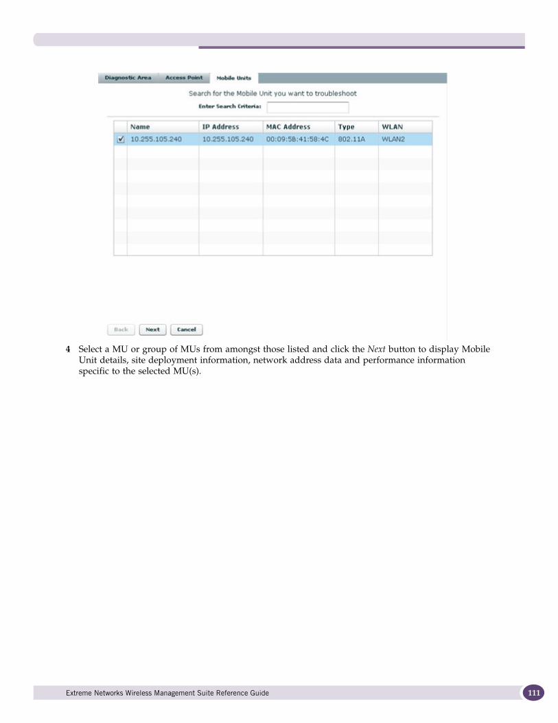
4 Select a MU or group of MUs from amongst those listed and click the Next button to display Mobile Unit details, site deployment information, network address data and performance information specific to the selected MU(s).
Extreme Networks Wireless Management Suite Reference Guide 111
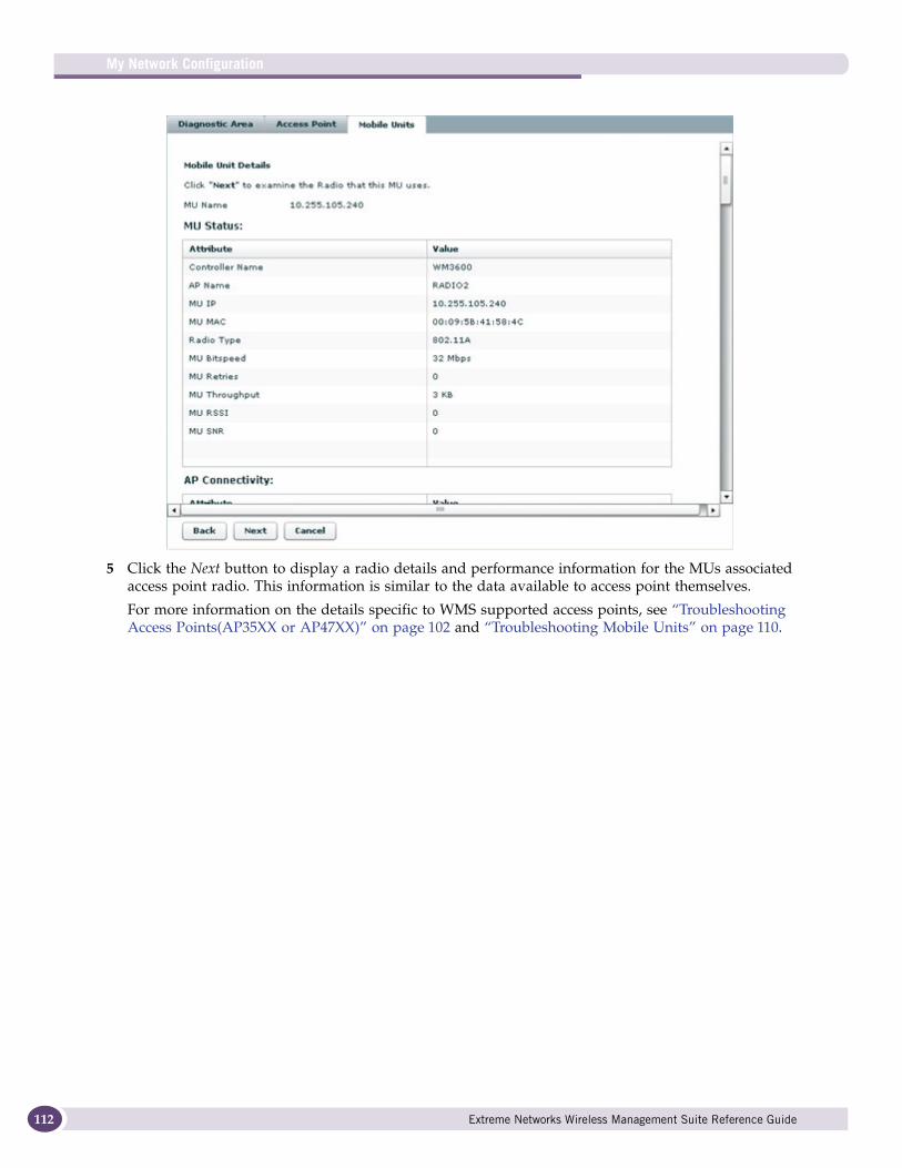
My Network Configuration
112
5 Click the Next button to display a radio details and performance information for the MUs associated access point radio. This information is similar to the data available to access point themselves.
For more information on the details specific to WMS supported access points, see “Troubleshooting Access Points(AP35XX or AP47XX)” on page 102 and “Troubleshooting Mobile Units” on page 110.
Extreme Networks Wireless Management Suite Reference Guide
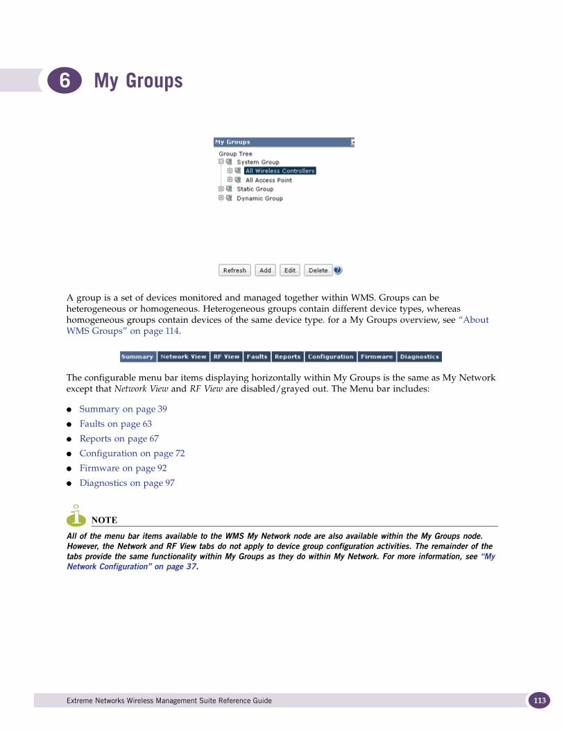
6 My Groups
A group is a set of devices monitored and managed together within WMS. Groups can be heterogeneous or homogeneous. Heterogeneous groups contain different device types, whereas homogeneous groups contain devices of the same device type. for a My Groups overview, see “About WMS Groups” on page 114.
The configurable menu bar items displaying horizontally within My Groups is the same as My Network except that Network View and RF View are disabled/grayed out. The Menu bar includes:
● Summary on page 39
● Faults on page 63
● Reports on page 67
● Configuration on page 72
● Firmware on page 92
● Diagnostics on page 97
NOTE
All of the menu bar items available to the WMS My Network node are also available within the My Groups node. However, the Network and RF View tabs do not apply to device group configuration activities. The remainder of the tabs provide the same functionality within My Groups as they do within My Network. For more information, see “My Network Configuration” on page 37.
Extreme Networks Wireless Management Suite Reference Guide 113

My Groups
114
About WMS GroupsGrouping allows portions of an enterprise segment to be viewed according to criteria appropriate for different management tasks. Further, grouping devices helps simplify complex management tasks by allowing otherwise repetitive tasks to be applied to device groups as opposed to one device at a time.
Groups are always virtual in nature. Groups maintain only device references and not real device instances. The life cycle of a device is not determined by the groups they belong to. If an administrator deletes a group, all device references within that group are deleted, but the actual device remains present in WMS. If a device is a member of a different group, it will continue to be a member of that group despite its deletion from the other group.
Groups are classified into System, Static, and Dynamic categories. These classifications have the following membership conditions:
NOTE
Devices in the My Groups tab can appear in more than one group.
● System - By default, WMS supports a set of pre-defined groups created in respect to the commonality of the devices supported within the group. You cannot add an additional group as a system group. Pre-defined system groups include:
● All Wireless Controllers- Contains the wireless controllers (across all sites) discovered by WMS
● All Access Points - Contains the access points (across all sites) discovered by WMS
● Static - A static group is one whose membership is fixed at the time the group is created and does not automatically change based on network conditions. The membership of a static group changes only if the user manually edits it or if a member device is purged from the WMS database. If the group is static, the WMS administrator has to provide the list of included devices when creating the group.
● Dynamic - A dynamic group is one whose membership is based on membership criteria defined when the group is created. The membership of the group is periodically re-evaluated (automatically) based on changing conditions. The list of group members may increase or decrease as the number of devices that meet the defined membership criteria changes. Users cannot add or delete devices, as dynamic groups are defined using the filter criteria set.
Groups can be created based on one or a combination of grouping criteria, including: IP Address, MAC Address, Model, Device Type, Firmware Version, Site Name and System Name. However, not all grouping criteria apply to all types of elements and devices.
NOTE
When a device is permanently deleted from the network, WMS removes its reference from relevant groups. If a device is detected as missing, it is automatically removed from any dynamic group to which it belonged. If the device is later determined to no longer be missing, it can be added to any dynamic group for which it meets the membership criteria.
For information on creating, modifying or deleting a group. Refer to:
● Adding a Group on page 115
● Editing an Existing Group on page 118
● Deleting a Group on page 119
Extreme Networks Wireless Management Suite Reference Guide
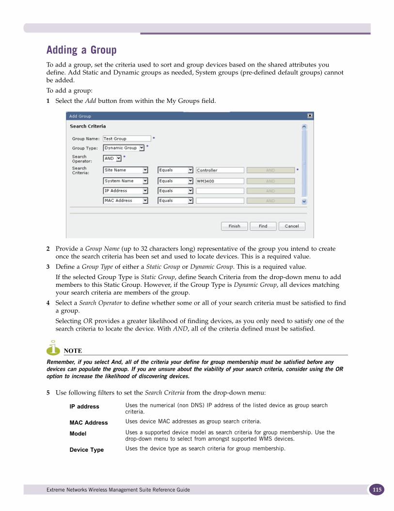
Adding a GroupTo add a group, set the criteria used to sort and group devices based on the shared attributes you define. Add Static and Dynamic groups as needed, System groups (pre-defined default groups) cannot be added.
To add a group:
1 Select the Add button from within the My Groups field.
2 Provide a Group Name (up to 32 characters long) representative of the group you intend to create once the search criteria has been set and used to locate devices. This is a required value.
3 Define a Group Type of either a Static Group or Dynamic Group. This is a required value.
If the selected Group Type is Static Group, define Search Criteria from the drop-down menu to add members to this Static Group. However, if the Group Type is Dynamic Group, all devices matching your search criteria are members of the group.
4 Select a Search Operator to define whether some or all of your search criteria must be satisfied to find a group.
Selecting OR provides a greater likelihood of finding devices, as you only need to satisfy one of the search criteria to locate the device. With AND, all of the criteria defined must be satisfied.
NOTE
Remember, if you select And, all of the criteria your define for group membership must be satisfied before any devices can populate the group. If you are unsure about the viability of your search criteria, consider using the OR option to increase the likelihood of discovering devices.
5 Use following filters to set the Search Criteria from the drop-down menu:
IP address Uses the numerical (non DNS) IP address of the listed device as group search criteria.
MAC Address Uses device MAC addresses as group search criteria.
Model Uses a supported device model as search criteria for group membership. Use the drop-down menu to select from amongst supported WMS devices.
Device Type Uses the device type as search criteria for group membership.
Extreme Networks Wireless Management Suite Reference Guide 115
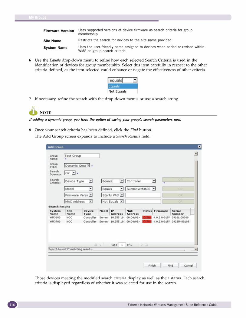
My Groups
116
6 Use the Equals drop-down menu to refine how each selected Search Criteria is used in the identification of devices for group membership. Select this item carefully in respect to the other criteria defined, as the item selected could enhance or negate the effectiveness of other criteria.
7 If necessary, refine the search with the drop-down menus or use a search string.
NOTE
If adding a dynamic group, you have the option of saving your group’s search parameters now.
8 Once your search criteria has been defined, click the Find button.
The Add Group screen expands to include a Search Results field.
Those devices meeting the modified search criteria display as well as their status. Each search criteria is displayed regardless of whether it was selected for use in the search.
Firmware Version Uses supported versions of device firmware as search criteria for group membership.
Site Name Restricts the search for devices to the site name provided.
System Name Uses the user-friendly name assigned to devices when added or revised within WMS as group search criteria.
Extreme Networks Wireless Management Suite Reference Guide

9 Use the Select checkboxes to select the devices you would like to include in the group from the total devices found by WMS in the device search.
10 Use the Select All option to include all located devices within the group. Selecting Deselect All negates their inclusion in the group.
11 Click the Save button to add the selected members to this group.
Depending on the selected group type (Static or Dynamic), the new group is added to the appropriate group within the My Groups menu.
12 Click Cancel to close the screen without committing the results of the search to a new group.
Extreme Networks Wireless Management Suite Reference Guide 117
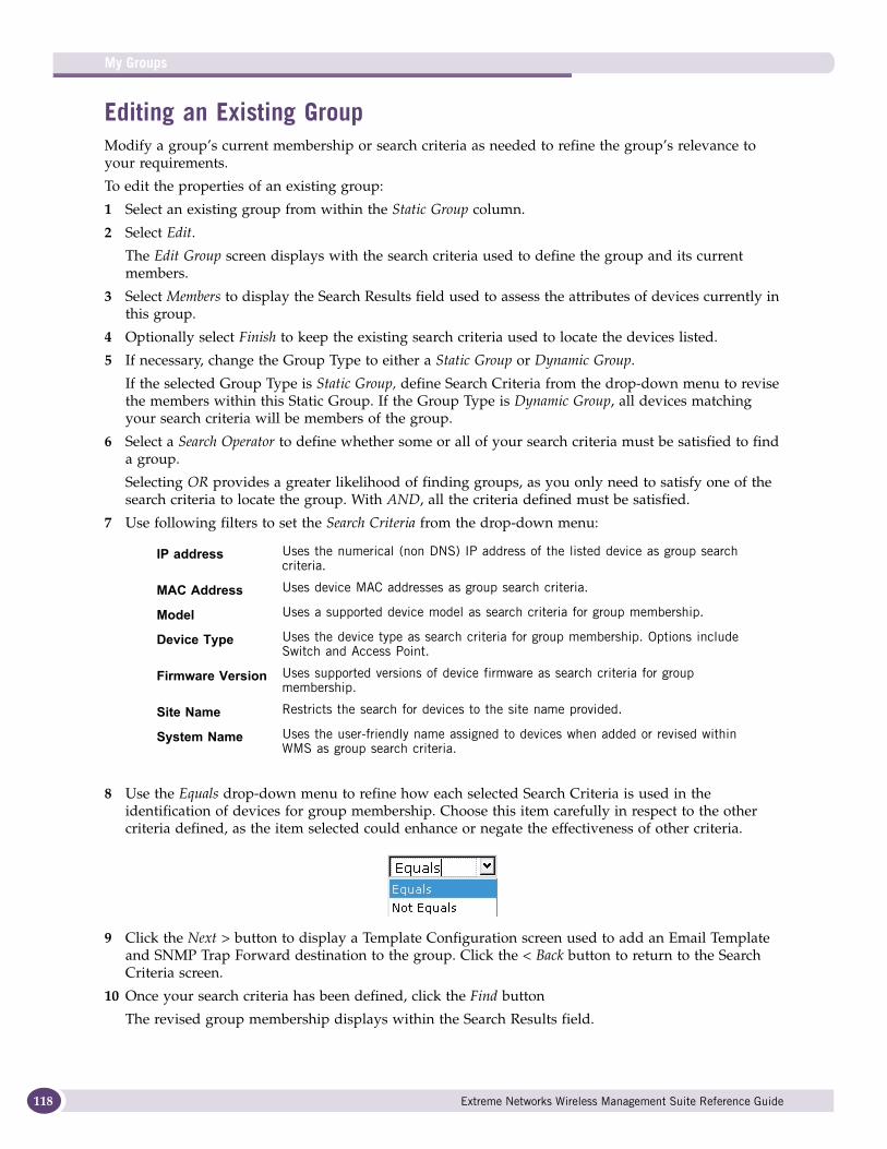
My Groups
118
Editing an Existing Group Modify a group’s current membership or search criteria as needed to refine the group’s relevance to your requirements.
To edit the properties of an existing group:
1 Select an existing group from within the Static Group column.
2 Select Edit.
The Edit Group screen displays with the search criteria used to define the group and its current members.
3 Select Members to display the Search Results field used to assess the attributes of devices currently in this group.
4 Optionally select Finish to keep the existing search criteria used to locate the devices listed.
5 If necessary, change the Group Type to either a Static Group or Dynamic Group.
If the selected Group Type is Static Group, define Search Criteria from the drop-down menu to revise the members within this Static Group. If the Group Type is Dynamic Group, all devices matching your search criteria will be members of the group.
6 Select a Search Operator to define whether some or all of your search criteria must be satisfied to find a group.
Selecting OR provides a greater likelihood of finding groups, as you only need to satisfy one of the search criteria to locate the group. With AND, all the criteria defined must be satisfied.
7 Use following filters to set the Search Criteria from the drop-down menu:
8 Use the Equals drop-down menu to refine how each selected Search Criteria is used in the identification of devices for group membership. Choose this item carefully in respect to the other criteria defined, as the item selected could enhance or negate the effectiveness of other criteria.
9 Click the Next > button to display a Template Configuration screen used to add an Email Template and SNMP Trap Forward destination to the group. Click the < Back button to return to the Search Criteria screen.
10 Once your search criteria has been defined, click the Find button
The revised group membership displays within the Search Results field.
IP address Uses the numerical (non DNS) IP address of the listed device as group search criteria.
MAC Address Uses device MAC addresses as group search criteria.
Model Uses a supported device model as search criteria for group membership.
Device Type Uses the device type as search criteria for group membership. Options include Switch and Access Point.
Firmware Version Uses supported versions of device firmware as search criteria for group membership.
Site Name Restricts the search for devices to the site name provided.
System Name Uses the user-friendly name assigned to devices when added or revised within WMS as group search criteria.
Extreme Networks Wireless Management Suite Reference Guide
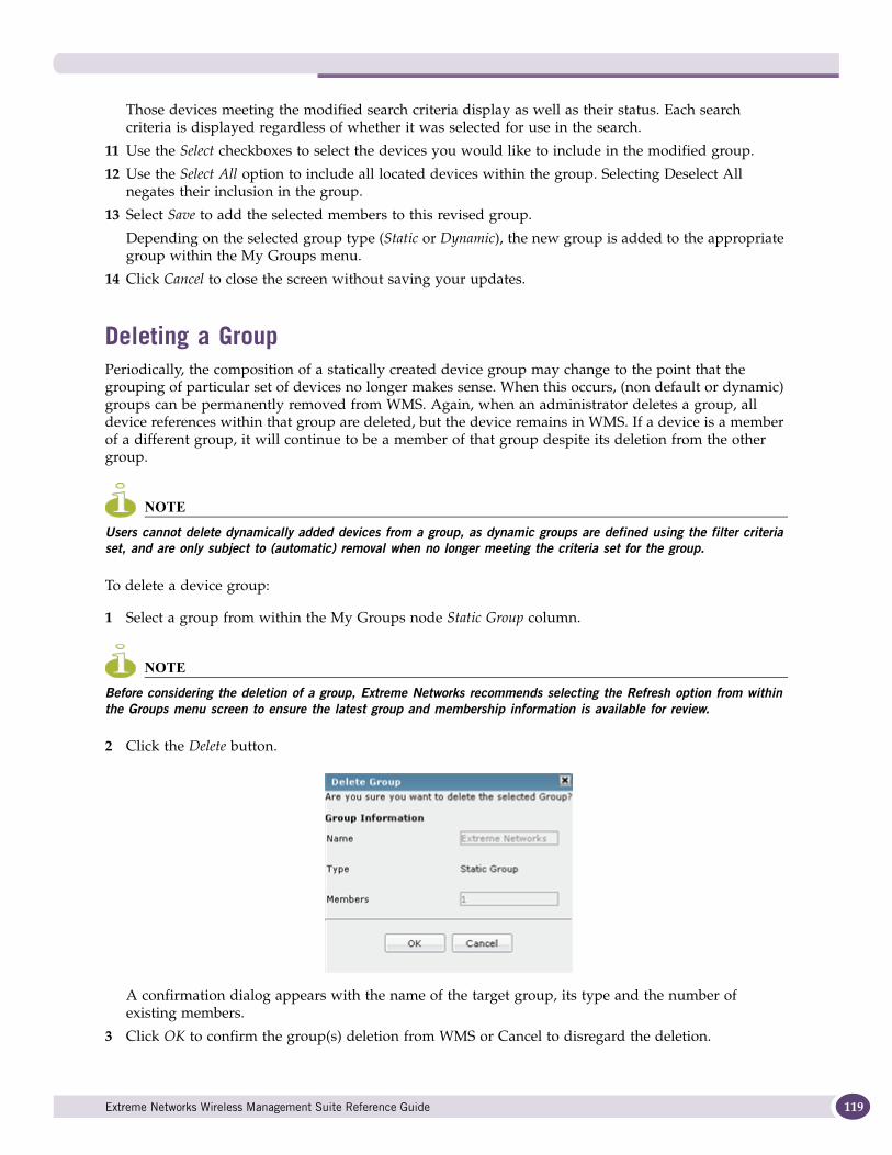
Those devices meeting the modified search criteria display as well as their status. Each search criteria is displayed regardless of whether it was selected for use in the search.
11 Use the Select checkboxes to select the devices you would like to include in the modified group.
12 Use the Select All option to include all located devices within the group. Selecting Deselect All negates their inclusion in the group.
13 Select Save to add the selected members to this revised group.
Depending on the selected group type (Static or Dynamic), the new group is added to the appropriate group within the My Groups menu.
14 Click Cancel to close the screen without saving your updates.
Deleting a GroupPeriodically, the composition of a statically created device group may change to the point that the grouping of particular set of devices no longer makes sense. When this occurs, (non default or dynamic) groups can be permanently removed from WMS. Again, when an administrator deletes a group, all device references within that group are deleted, but the device remains in WMS. If a device is a member of a different group, it will continue to be a member of that group despite its deletion from the other group.
NOTE
Users cannot delete dynamically added devices from a group, as dynamic groups are defined using the filter criteria set, and are only subject to (automatic) removal when no longer meeting the criteria set for the group.
To delete a device group:
1 Select a group from within the My Groups node Static Group column.
NOTE
Before considering the deletion of a group, Extreme Networks recommends selecting the Refresh option from within the Groups menu screen to ensure the latest group and membership information is available for review.
2 Click the Delete button.
A confirmation dialog appears with the name of the target group, its type and the number of existing members.
3 Click OK to confirm the group(s) deletion from WMS or Cancel to disregard the deletion.
Extreme Networks Wireless Management Suite Reference Guide 119

My Groups
120
The deleted group is no longer listed within the My Group menu.
Extreme Networks Wireless Management Suite Reference Guide
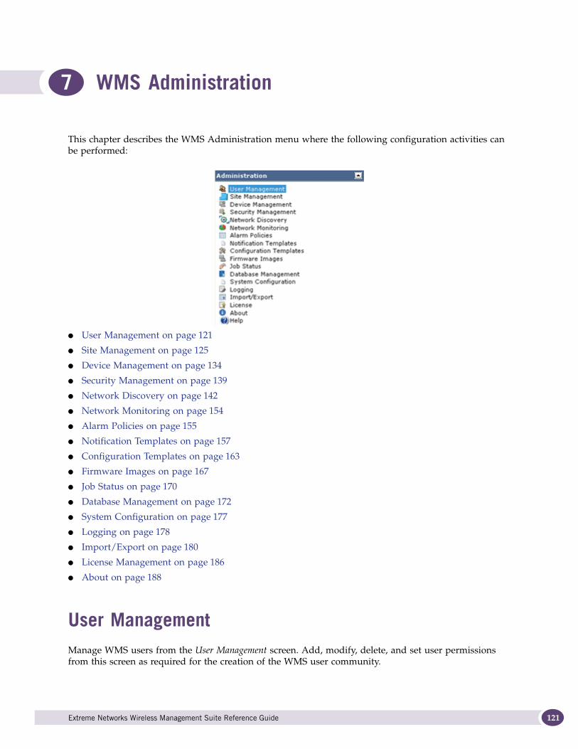
7 WMS Administration
This chapter describes the WMS Administration menu where the following configuration activities can be performed:
● User Management on page 121
● Site Management on page 125
● Device Management on page 134
● Security Management on page 139
● Network Discovery on page 142
● Network Monitoring on page 154
● Alarm Policies on page 155
● Notification Templates on page 157
● Configuration Templates on page 163
● Firmware Images on page 167
● Job Status on page 170
● Database Management on page 172
● System Configuration on page 177
● Logging on page 178
● Import/Export on page 180
● License Management on page 186
● About on page 188
User ManagementManage WMS users from the User Management screen. Add, modify, delete, and set user permissions from this screen as required for the creation of the WMS user community.
Extreme Networks Wireless Management Suite Reference Guide 121
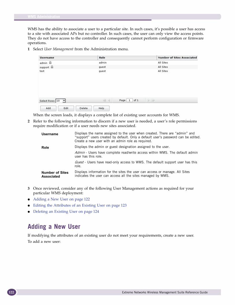
WMS Administration
122
WMS has the ability to associate a user to a particular site. In such cases, it’s possible a user has access to a site with associated APs but no controller. In such cases, the user can only view the access points. They do not have access to the controller and consequently cannot perform configuration or firmware operations.
1 Select User Management from the Administration menu.
When the screen loads, it displays a complete list of existing user accounts for WMS.
2 Refer to the following information to discern if a new user is needed, a user’s role permissions require modification or if a user needs new sites associated.
3 Once reviewed, consider any of the following User Management actions as required for your particular WMS deployment:
● Adding a New User on page 122
● Editing the Attributes of an Existing User on page 123
● Deleting an Existing User on page 124
Adding a New UserIf modifying the attributes of an existing user do not meet your requirements, create a new user.
To add a new user:
Username Displays the name assigned to the user when created. There are “admin” and “support” users created by default. Only a default user’s password can be edited. Create a new user with an admin role as required.
Role Displays the admin or guest designation assigned to the user.
Admin - Users have complete read/write access within WMS. The default admin user has this role.
Guest - Users have read-only access to WMS. The default support user has this role.
Number of Sites Associated
Displays information for the sites the user can access or manage. All Sites indicates the user can access all the sites managed by WMS.
Extreme Networks Wireless Management Suite Reference Guide
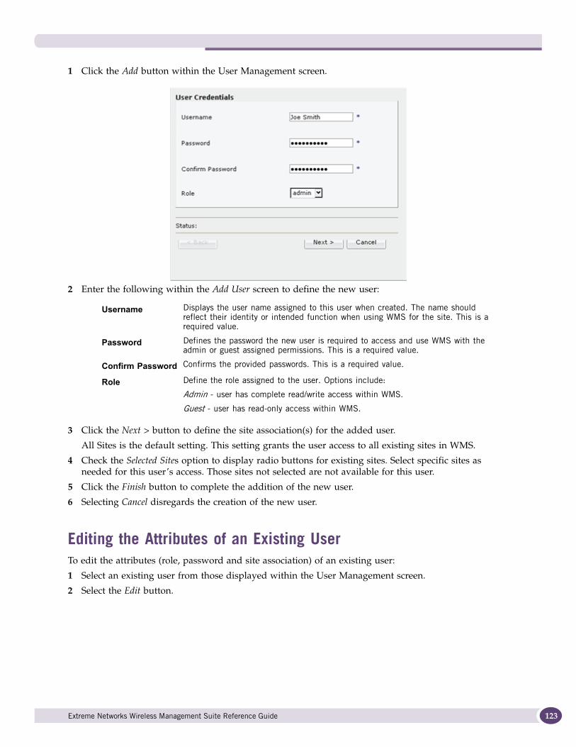
1 Click the Add button within the User Management screen.
2 Enter the following within the Add User screen to define the new user:
3 Click the Next > button to define the site association(s) for the added user.
All Sites is the default setting. This setting grants the user access to all existing sites in WMS.
4 Check the Selected Sites option to display radio buttons for existing sites. Select specific sites as needed for this user’s access. Those sites not selected are not available for this user.
5 Click the Finish button to complete the addition of the new user.
6 Selecting Cancel disregards the creation of the new user.
Editing the Attributes of an Existing UserTo edit the attributes (role, password and site association) of an existing user:
1 Select an existing user from those displayed within the User Management screen.
2 Select the Edit button.
Username Displays the user name assigned to this user when created. The name should reflect their identity or intended function when using WMS for the site. This is a required value.
Password Defines the password the new user is required to access and use WMS with the admin or guest assigned permissions. This is a required value.
Confirm Password Confirms the provided passwords. This is a required value.
Role Define the role assigned to the user. Options include:
Admin - user has complete read/write access within WMS.
Guest - user has read-only access within WMS.
Extreme Networks Wireless Management Suite Reference Guide 123
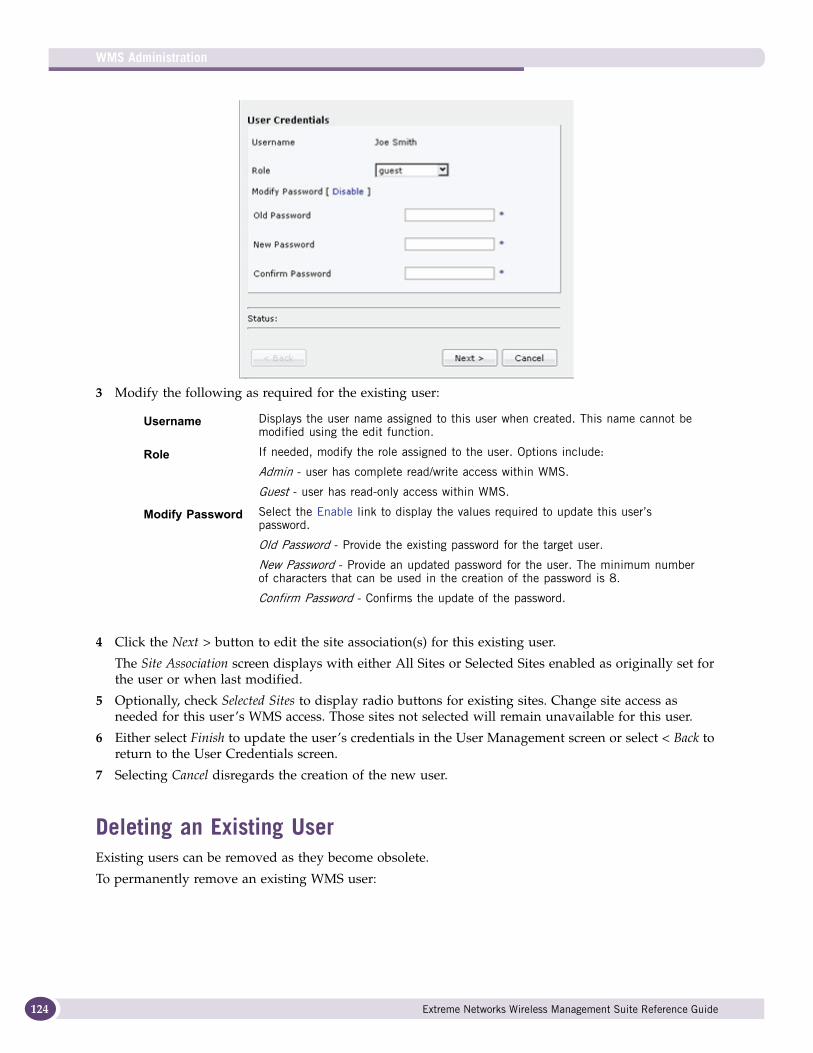
WMS Administration
124
3 Modify the following as required for the existing user:
4 Click the Next > button to edit the site association(s) for this existing user.
The Site Association screen displays with either All Sites or Selected Sites enabled as originally set for the user or when last modified.
5 Optionally, check Selected Sites to display radio buttons for existing sites. Change site access as needed for this user’s WMS access. Those sites not selected will remain unavailable for this user.
6 Either select Finish to update the user’s credentials in the User Management screen or select < Back to return to the User Credentials screen.
7 Selecting Cancel disregards the creation of the new user.
Deleting an Existing UserExisting users can be removed as they become obsolete.
To permanently remove an existing WMS user:
Username Displays the user name assigned to this user when created. This name cannot be modified using the edit function.
Role If needed, modify the role assigned to the user. Options include:
Admin - user has complete read/write access within WMS.
Guest - user has read-only access within WMS.
Modify Password Select the Enable link to display the values required to update this user’s password.
Old Password - Provide the existing password for the target user.
New Password - Provide an updated password for the user. The minimum number of characters that can be used in the creation of the password is 8.
Confirm Password - Confirms the update of the password.
Extreme Networks Wireless Management Suite Reference Guide
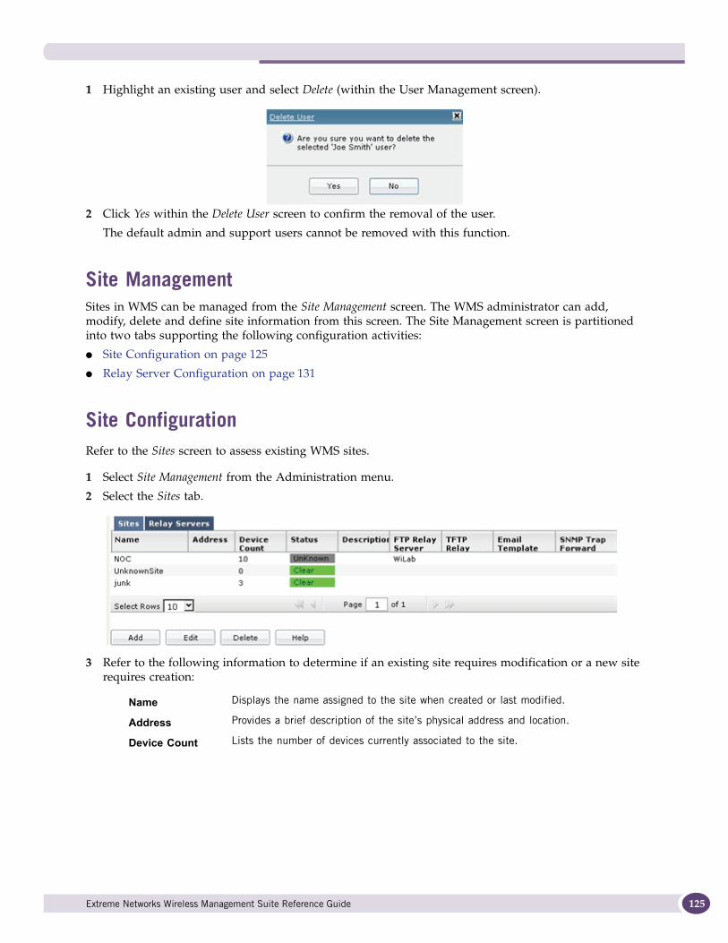
1 Highlight an existing user and select Delete (within the User Management screen).
2 Click Yes within the Delete User screen to confirm the removal of the user.
The default admin and support users cannot be removed with this function.
Site ManagementSites in WMS can be managed from the Site Management screen. The WMS administrator can add, modify, delete and define site information from this screen. The Site Management screen is partitioned into two tabs supporting the following configuration activities:
● Site Configuration on page 125
● Relay Server Configuration on page 131
Site ConfigurationRefer to the Sites screen to assess existing WMS sites.
1 Select Site Management from the Administration menu.
2 Select the Sites tab.
3 Refer to the following information to determine if an existing site requires modification or a new site requires creation:
Name Displays the name assigned to the site when created or last modified.
Address Provides a brief description of the site’s physical address and location.
Device Count Lists the number of devices currently associated to the site.
Extreme Networks Wireless Management Suite Reference Guide 125
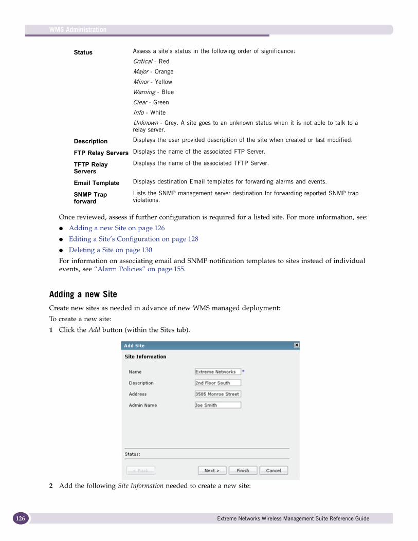
WMS Administration
126
Once reviewed, assess if further configuration is required for a listed site. For more information, see:
● Adding a new Site on page 126
● Editing a Site’s Configuration on page 128
● Deleting a Site on page 130
For information on associating email and SNMP notification templates to sites instead of individual events, see “Alarm Policies” on page 155.
Adding a new SiteCreate new sites as needed in advance of new WMS managed deployment:
To create a new site:
1 Click the Add button (within the Sites tab).
2 Add the following Site Information needed to create a new site:
Status Assess a site’s status in the following order of significance:
Critical - Red
Major - Orange
Minor - Yellow
Warning - Blue
Clear - Green
Info - White
Unknown - Grey. A site goes to an unknown status when it is not able to talk to a relay server.
Description Displays the user provided description of the site when created or last modified.
FTP Relay Servers Displays the name of the associated FTP Server.
TFTP Relay Servers
Displays the name of the associated TFTP Server.
Email Template Displays destination Email templates for forwarding alarms and events.
SNMP Trap forward
Lists the SNMP management server destination for forwarding reported SNMP trap violations.
Extreme Networks Wireless Management Suite Reference Guide
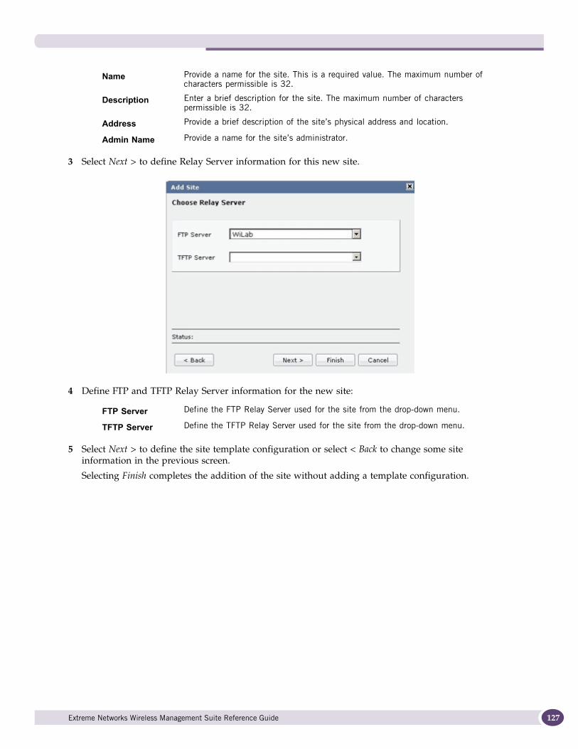
3 Select Next > to define Relay Server information for this new site.
4 Define FTP and TFTP Relay Server information for the new site:
5 Select Next > to define the site template configuration or select < Back to change some site information in the previous screen.
Selecting Finish completes the addition of the site without adding a template configuration.
Name Provide a name for the site. This is a required value. The maximum number of characters permissible is 32.
Description Enter a brief description for the site. The maximum number of characters permissible is 32.
Address Provide a brief description of the site’s physical address and location.
Admin Name Provide a name for the site’s administrator.
FTP Server Define the FTP Relay Server used for the site from the drop-down menu.
TFTP Server Define the TFTP Relay Server used for the site from the drop-down menu.
Extreme Networks Wireless Management Suite Reference Guide 127
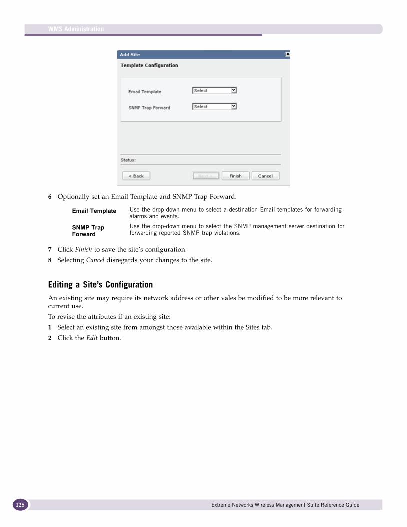
WMS Administration
128
6 Optionally set an Email Template and SNMP Trap Forward.
7 Click Finish to save the site’s configuration.
8 Selecting Cancel disregards your changes to the site.
Editing a Site’s ConfigurationAn existing site may require its network address or other vales be modified to be more relevant to current use.
To revise the attributes if an existing site:
1 Select an existing site from amongst those available within the Sites tab.
2 Click the Edit button.
Email Template Use the drop-down menu to select a destination Email templates for forwarding alarms and events.
SNMP Trap Forward
Use the drop-down menu to select the SNMP management server destination for forwarding reported SNMP trap violations.
Extreme Networks Wireless Management Suite Reference Guide
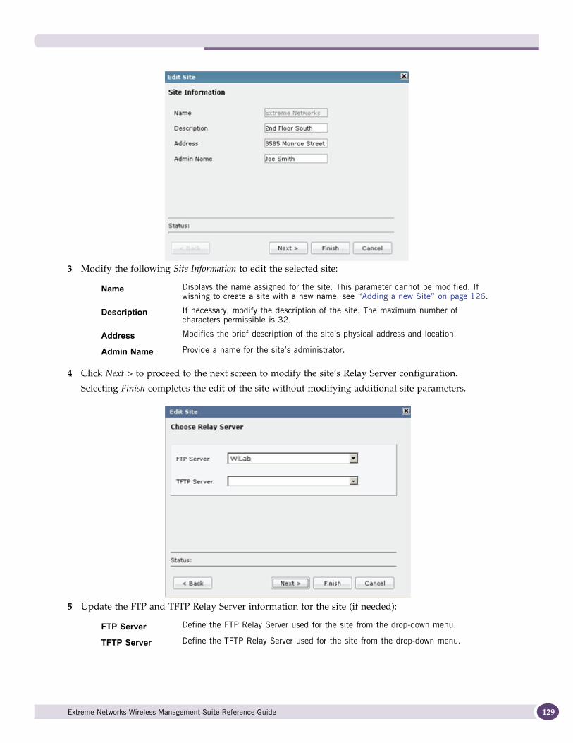
3 Modify the following Site Information to edit the selected site:
4 Click Next > to proceed to the next screen to modify the site’s Relay Server configuration.
Selecting Finish completes the edit of the site without modifying additional site parameters.
5 Update the FTP and TFTP Relay Server information for the site (if needed):
Name Displays the name assigned for the site. This parameter cannot be modified. If wishing to create a site with a new name, see “Adding a new Site” on page 126.
Description If necessary, modify the description of the site. The maximum number of characters permissible is 32.
Address Modifies the brief description of the site’s physical address and location.
Admin Name Provide a name for the site’s administrator.
FTP Server Define the FTP Relay Server used for the site from the drop-down menu.
TFTP Server Define the TFTP Relay Server used for the site from the drop-down menu.
Extreme Networks Wireless Management Suite Reference Guide 129
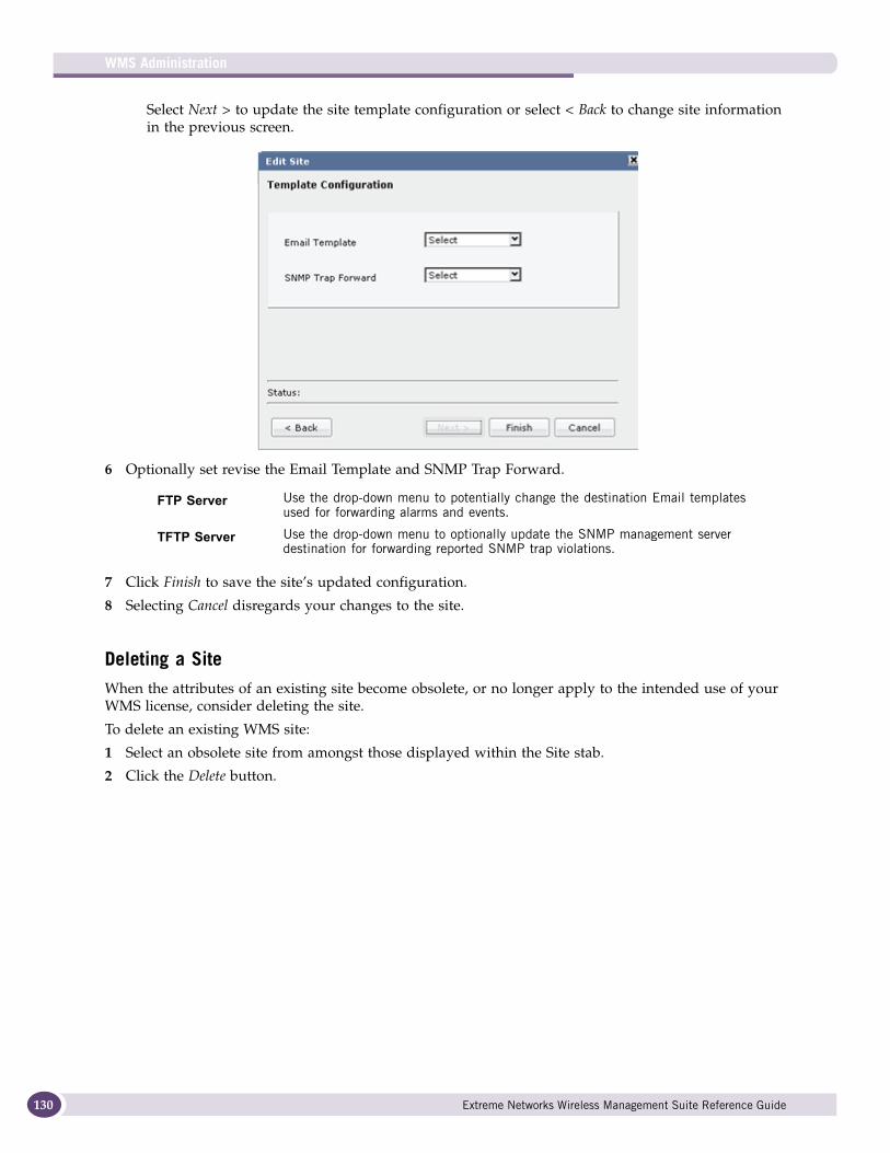
WMS Administration
130
Select Next > to update the site template configuration or select < Back to change site information in the previous screen.
6 Optionally set revise the Email Template and SNMP Trap Forward.
7 Click Finish to save the site’s updated configuration.
8 Selecting Cancel disregards your changes to the site.
Deleting a SiteWhen the attributes of an existing site become obsolete, or no longer apply to the intended use of your WMS license, consider deleting the site.
To delete an existing WMS site:
1 Select an obsolete site from amongst those displayed within the Site stab.
2 Click the Delete button.
FTP Server Use the drop-down menu to potentially change the destination Email templates used for forwarding alarms and events.
TFTP Server Use the drop-down menu to optionally update the SNMP management server destination for forwarding reported SNMP trap violations.
Extreme Networks Wireless Management Suite Reference Guide
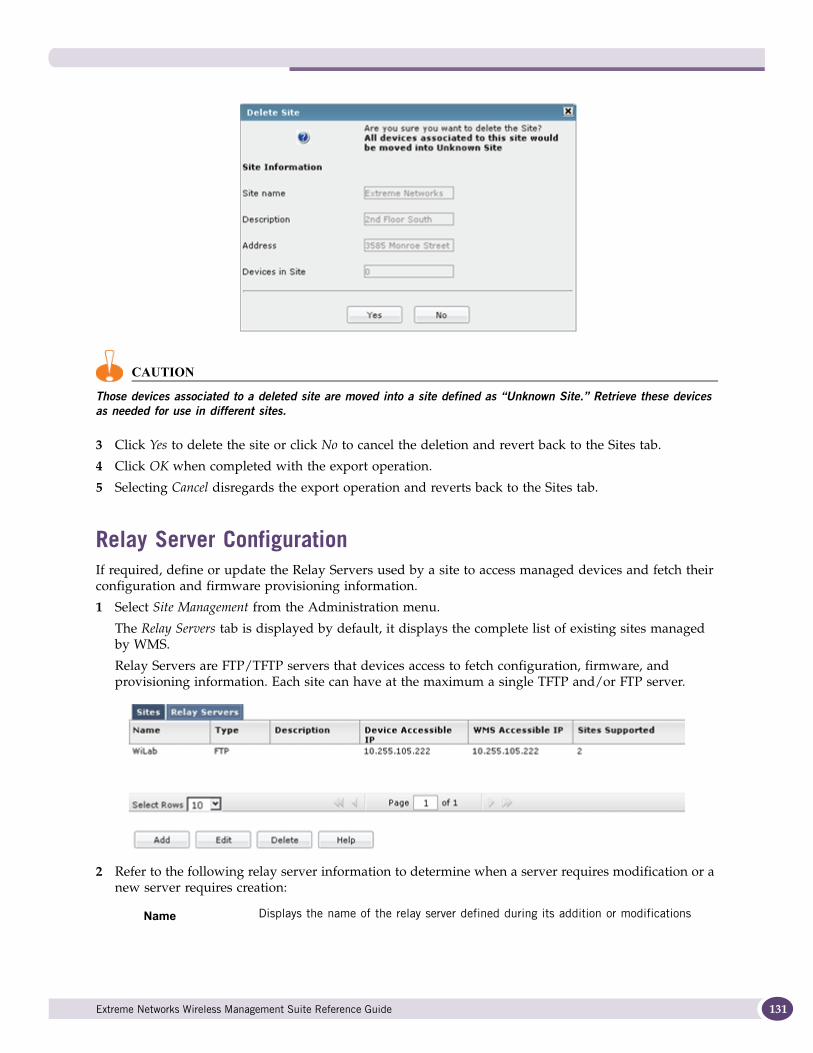
CAUTION
Those devices associated to a deleted site are moved into a site defined as “Unknown Site.” Retrieve these devices as needed for use in different sites.
3 Click Yes to delete the site or click No to cancel the deletion and revert back to the Sites tab.
4 Click OK when completed with the export operation.
5 Selecting Cancel disregards the export operation and reverts back to the Sites tab.
Relay Server ConfigurationIf required, define or update the Relay Servers used by a site to access managed devices and fetch their configuration and firmware provisioning information.
1 Select Site Management from the Administration menu.
The Relay Servers tab is displayed by default, it displays the complete list of existing sites managed by WMS.
Relay Servers are FTP/TFTP servers that devices access to fetch configuration, firmware, and provisioning information. Each site can have at the maximum a single TFTP and/or FTP server.
2 Refer to the following relay server information to determine when a server requires modification or a new server requires creation:
Name Displays the name of the relay server defined during its addition or modifications
Extreme Networks Wireless Management Suite Reference Guide 131
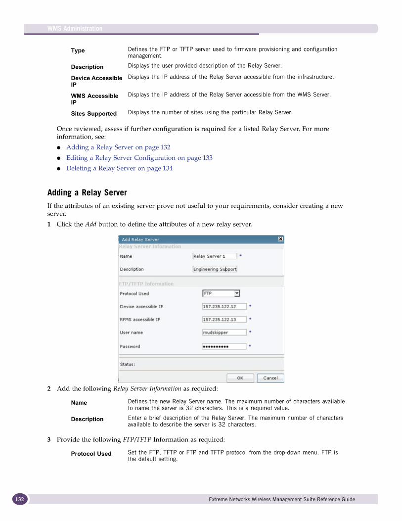
WMS Administration
132
Once reviewed, assess if further configuration is required for a listed Relay Server. For more information, see:
● Adding a Relay Server on page 132
● Editing a Relay Server Configuration on page 133
● Deleting a Relay Server on page 134
Adding a Relay ServerIf the attributes of an existing server prove not useful to your requirements, consider creating a new server.
1 Click the Add button to define the attributes of a new relay server.
2 Add the following Relay Server Information as required:
3 Provide the following FTP/TFTP Information as required:
Type Defines the FTP or TFTP server used to firmware provisioning and configuration management.
Description Displays the user provided description of the Relay Server.
Device Accessible IP
Displays the IP address of the Relay Server accessible from the infrastructure.
WMS Accessible IP
Displays the IP address of the Relay Server accessible from the WMS Server.
Sites Supported Displays the number of sites using the particular Relay Server.
Name Defines the new Relay Server name. The maximum number of characters available to name the server is 32 characters. This is a required value.
Description Enter a brief description of the Relay Server. The maximum number of characters available to describe the server is 32 characters.
Protocol Used Set the FTP, TFTP or FTP and TFTP protocol from the drop-down menu. FTP is the default setting.
Extreme Networks Wireless Management Suite Reference Guide
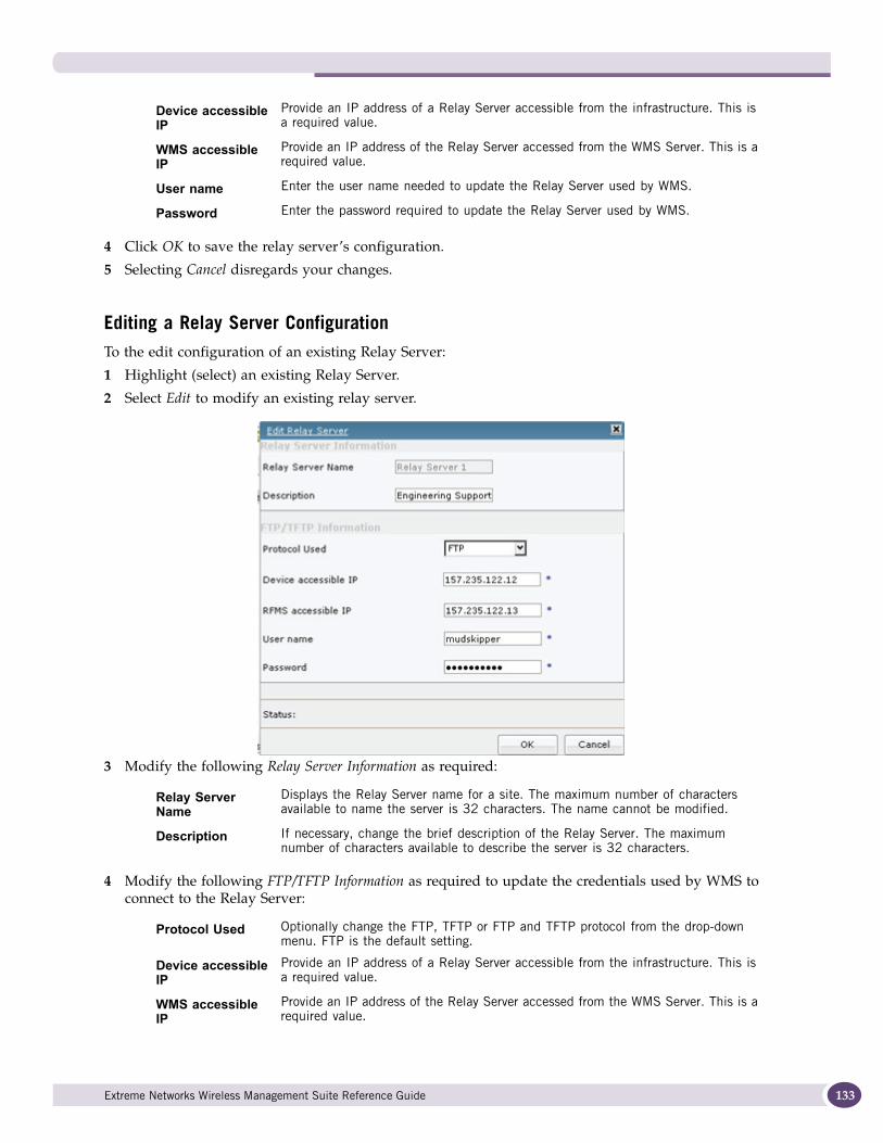
4 Click OK to save the relay server’s configuration.
5 Selecting Cancel disregards your changes.
Editing a Relay Server ConfigurationTo the edit configuration of an existing Relay Server:
1 Highlight (select) an existing Relay Server.
2 Select Edit to modify an existing relay server.
3 Modify the following Relay Server Information as required:
4 Modify the following FTP/TFTP Information as required to update the credentials used by WMS to connect to the Relay Server:
Device accessible IP
Provide an IP address of a Relay Server accessible from the infrastructure. This is a required value.
WMS accessible IP
Provide an IP address of the Relay Server accessed from the WMS Server. This is a required value.
User name Enter the user name needed to update the Relay Server used by WMS.
Password Enter the password required to update the Relay Server used by WMS.
Relay Server Name
Displays the Relay Server name for a site. The maximum number of characters available to name the server is 32 characters. The name cannot be modified.
Description If necessary, change the brief description of the Relay Server. The maximum number of characters available to describe the server is 32 characters.
Protocol Used Optionally change the FTP, TFTP or FTP and TFTP protocol from the drop-down menu. FTP is the default setting.
Device accessible IP
Provide an IP address of a Relay Server accessible from the infrastructure. This is a required value.
WMS accessible IP
Provide an IP address of the Relay Server accessed from the WMS Server. This is a required value.
Extreme Networks Wireless Management Suite Reference Guide 133
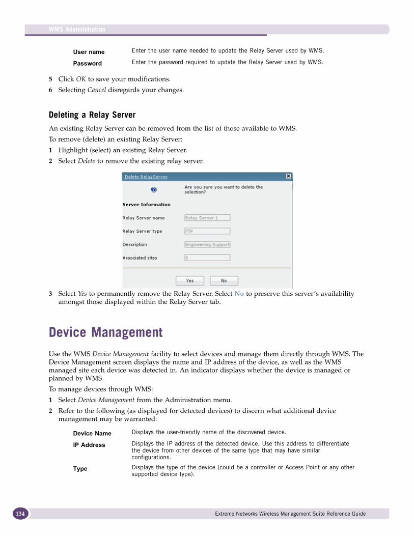
WMS Administration
134
5 Click OK to save your modifications.
6 Selecting Cancel disregards your changes.
Deleting a Relay ServerAn existing Relay Server can be removed from the list of those available to WMS.
To remove (delete) an existing Relay Server:
1 Highlight (select) an existing Relay Server.
2 Select Delete to remove the existing relay server.
3 Select Yes to permanently remove the Relay Server. Select No to preserve this server’s availability amongst those displayed within the Relay Server tab.
Device ManagementUse the WMS Device Management facility to select devices and manage them directly through WMS. The Device Management screen displays the name and IP address of the device, as well as the WMS managed site each device was detected in. An indicator displays whether the device is managed or planned by WMS.
To manage devices through WMS:
1 Select Device Management from the Administration menu.
2 Refer to the following (as displayed for detected devices) to discern what additional device management may be warranted:
User name Enter the user name needed to update the Relay Server used by WMS.
Password Enter the password required to update the Relay Server used by WMS.
Device Name Displays the user-friendly name of the discovered device.
IP Address Displays the IP address of the detected device. Use this address to differentiate the device from other devices of the same type that may have similar configurations.
Type Displays the type of the device (could be a controller or Access Point or any other supported device type).
Extreme Networks Wireless Management Suite Reference Guide
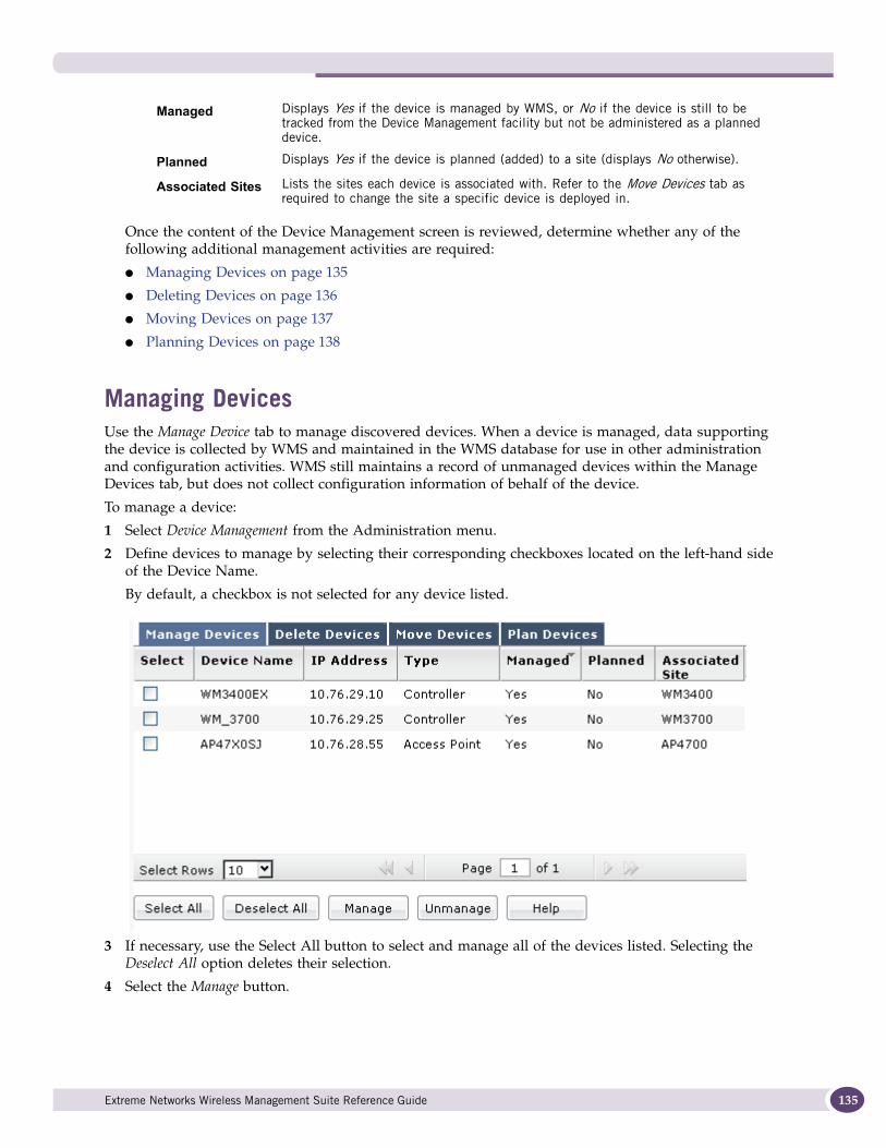
Once the content of the Device Management screen is reviewed, determine whether any of the following additional management activities are required:
● Managing Devices on page 135
● Deleting Devices on page 136
● Moving Devices on page 137
● Planning Devices on page 138
Managing DevicesUse the Manage Device tab to manage discovered devices. When a device is managed, data supporting the device is collected by WMS and maintained in the WMS database for use in other administration and configuration activities. WMS still maintains a record of unmanaged devices within the Manage Devices tab, but does not collect configuration information of behalf of the device.
To manage a device:
1 Select Device Management from the Administration menu.
2 Define devices to manage by selecting their corresponding checkboxes located on the left-hand side of the Device Name.
By default, a checkbox is not selected for any device listed.
3 If necessary, use the Select All button to select and manage all of the devices listed. Selecting the Deselect All option deletes their selection.
4 Select the Manage button.
Managed Displays Yes if the device is managed by WMS, or No if the device is still to be tracked from the Device Management facility but not be administered as a planned device.
Planned Displays Yes if the device is planned (added) to a site (displays No otherwise).
Associated Sites Lists the sites each device is associated with. Refer to the Move Devices tab as required to change the site a specific device is deployed in.
Extreme Networks Wireless Management Suite Reference Guide 135
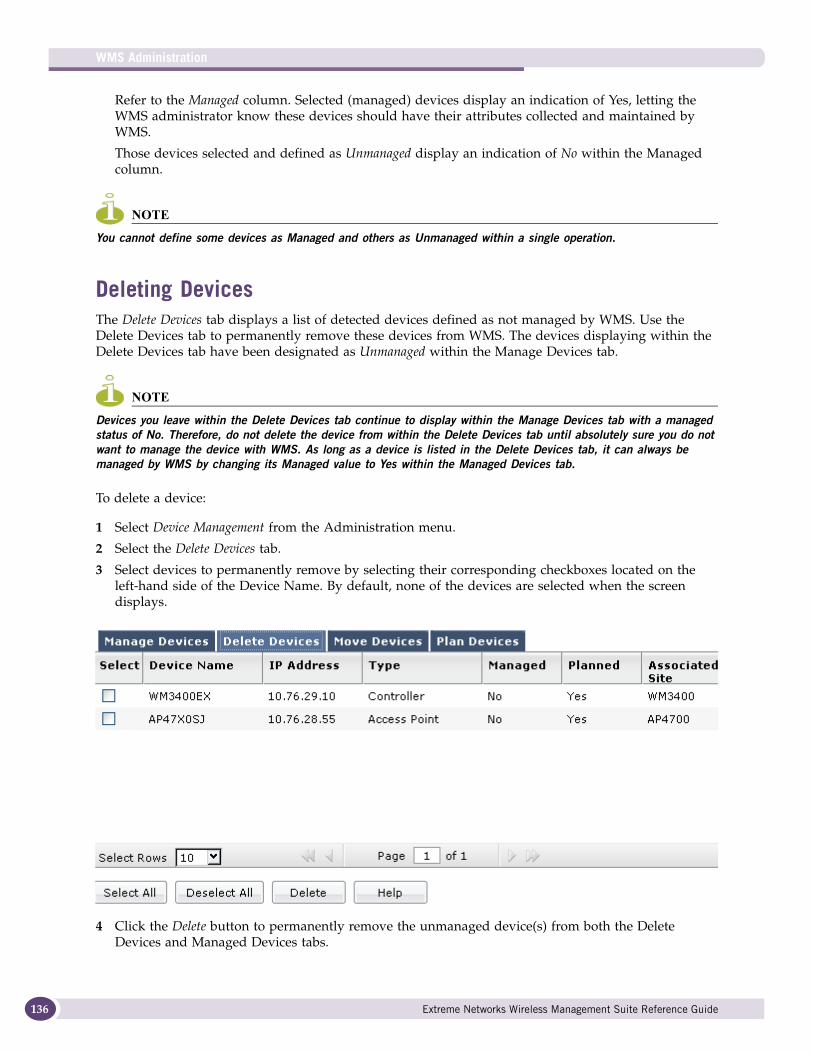
WMS Administration
136
Refer to the Managed column. Selected (managed) devices display an indication of Yes, letting the WMS administrator know these devices should have their attributes collected and maintained by WMS.
Those devices selected and defined as Unmanaged display an indication of No within the Managed column.
NOTE
You cannot define some devices as Managed and others as Unmanaged within a single operation.
Deleting DevicesThe Delete Devices tab displays a list of detected devices defined as not managed by WMS. Use the Delete Devices tab to permanently remove these devices from WMS. The devices displaying within the Delete Devices tab have been designated as Unmanaged within the Manage Devices tab.
NOTE
Devices you leave within the Delete Devices tab continue to display within the Manage Devices tab with a managed status of No. Therefore, do not delete the device from within the Delete Devices tab until absolutely sure you do not want to manage the device with WMS. As long as a device is listed in the Delete Devices tab, it can always be managed by WMS by changing its Managed value to Yes within the Managed Devices tab.
To delete a device:
1 Select Device Management from the Administration menu.
2 Select the Delete Devices tab.
3 Select devices to permanently remove by selecting their corresponding checkboxes located on the left-hand side of the Device Name. By default, none of the devices are selected when the screen displays.
4 Click the Delete button to permanently remove the unmanaged device(s) from both the Delete Devices and Managed Devices tabs.
Extreme Networks Wireless Management Suite Reference Guide
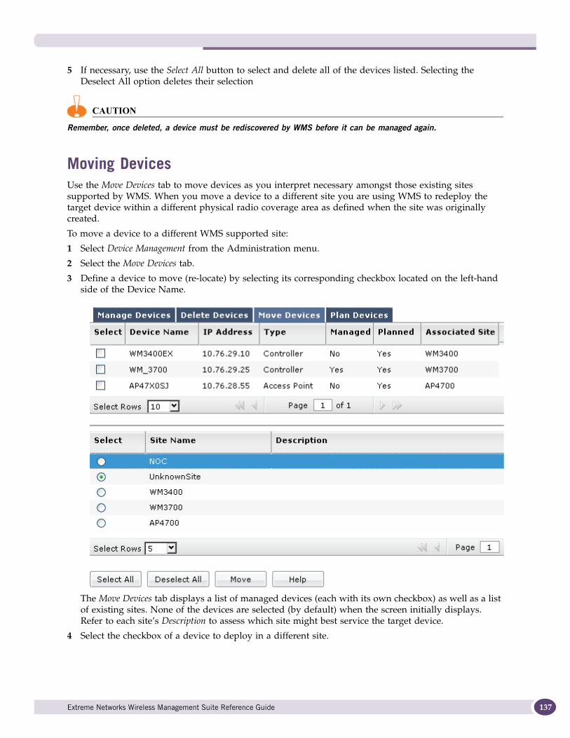
5 If necessary, use the Select All button to select and delete all of the devices listed. Selecting the Deselect All option deletes their selection
CAUTION
Remember, once deleted, a device must be rediscovered by WMS before it can be managed again.
Moving DevicesUse the Move Devices tab to move devices as you interpret necessary amongst those existing sites supported by WMS. When you move a device to a different site you are using WMS to redeploy the target device within a different physical radio coverage area as defined when the site was originally created.
To move a device to a different WMS supported site:
1 Select Device Management from the Administration menu.
2 Select the Move Devices tab.
3 Define a device to move (re-locate) by selecting its corresponding checkbox located on the left-hand side of the Device Name.
The Move Devices tab displays a list of managed devices (each with its own checkbox) as well as a list of existing sites. None of the devices are selected (by default) when the screen initially displays. Refer to each site’s Description to assess which site might best service the target device.
4 Select the checkbox of a device to deploy in a different site.
Extreme Networks Wireless Management Suite Reference Guide 137
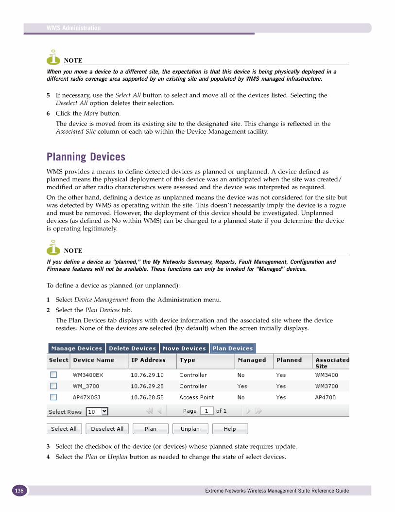
WMS Administration
138
NOTE
When you move a device to a different site, the expectation is that this device is being physically deployed in a different radio coverage area supported by an existing site and populated by WMS managed infrastructure.
5 If necessary, use the Select All button to select and move all of the devices listed. Selecting the Deselect All option deletes their selection.
6 Click the Move button.
The device is moved from its existing site to the designated site. This change is reflected in the Associated Site column of each tab within the Device Management facility.
Planning DevicesWMS provides a means to define detected devices as planned or unplanned. A device defined as planned means the physical deployment of this device was an anticipated when the site was created/modified or after radio characteristics were assessed and the device was interpreted as required.
On the other hand, defining a device as unplanned means the device was not considered for the site but was detected by WMS as operating within the site. This doesn’t necessarily imply the device is a rogue and must be removed. However, the deployment of this device should be investigated. Unplanned devices (as defined as No within WMS) can be changed to a planned state if you determine the device is operating legitimately.
NOTE
If you define a device as “planned,” the My Networks Summary, Reports, Fault Management, Configuration and Firmware features will not be available. These functions can only be invoked for “Managed” devices.
To define a device as planned (or unplanned):
1 Select Device Management from the Administration menu.
2 Select the Plan Devices tab.
The Plan Devices tab displays with device information and the associated site where the device resides. None of the devices are selected (by default) when the screen initially displays.
3 Select the checkbox of the device (or devices) whose planned state requires update.
4 Select the Plan or Unplan button as needed to change the state of select devices.
Extreme Networks Wireless Management Suite Reference Guide
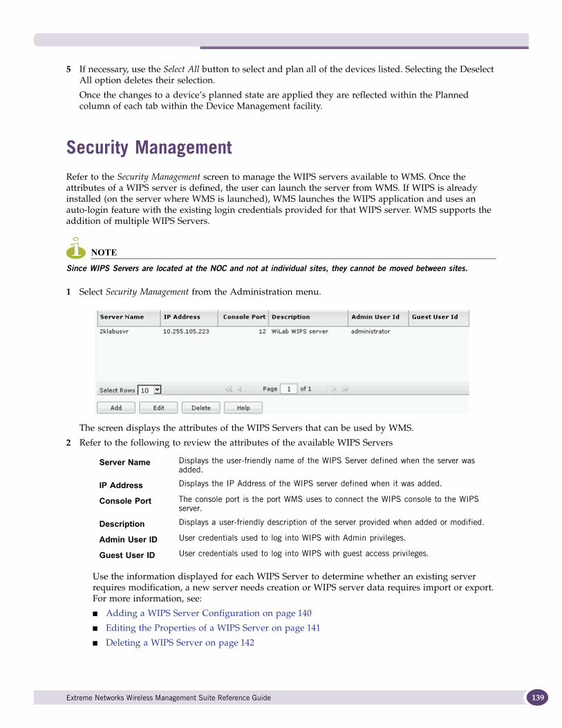
5 If necessary, use the Select All button to select and plan all of the devices listed. Selecting the Deselect All option deletes their selection.
Once the changes to a device’s planned state are applied they are reflected within the Planned column of each tab within the Device Management facility.
Security ManagementRefer to the Security Management screen to manage the WIPS servers available to WMS. Once the attributes of a WIPS server is defined, the user can launch the server from WMS. If WIPS is already installed (on the server where WMS is launched), WMS launches the WIPS application and uses an auto-login feature with the existing login credentials provided for that WIPS server. WMS supports the addition of multiple WIPS Servers.
NOTE
Since WIPS Servers are located at the NOC and not at individual sites, they cannot be moved between sites.
1 Select Security Management from the Administration menu.
The screen displays the attributes of the WIPS Servers that can be used by WMS.
2 Refer to the following to review the attributes of the available WIPS Servers
Use the information displayed for each WIPS Server to determine whether an existing server requires modification, a new server needs creation or WIPS server data requires import or export. For more information, see:
■ Adding a WIPS Server Configuration on page 140
■ Editing the Properties of a WIPS Server on page 141
■ Deleting a WIPS Server on page 142
Server Name Displays the user-friendly name of the WIPS Server defined when the server was added.
IP Address Displays the IP Address of the WIPS server defined when it was added.
Console Port The console port is the port WMS uses to connect the WIPS console to the WIPS server.
Description Displays a user-friendly description of the server provided when added or modified.
Admin User ID User credentials used to log into WIPS with Admin privileges.
Guest User ID User credentials used to log into WIPS with guest access privileges.
Extreme Networks Wireless Management Suite Reference Guide 139
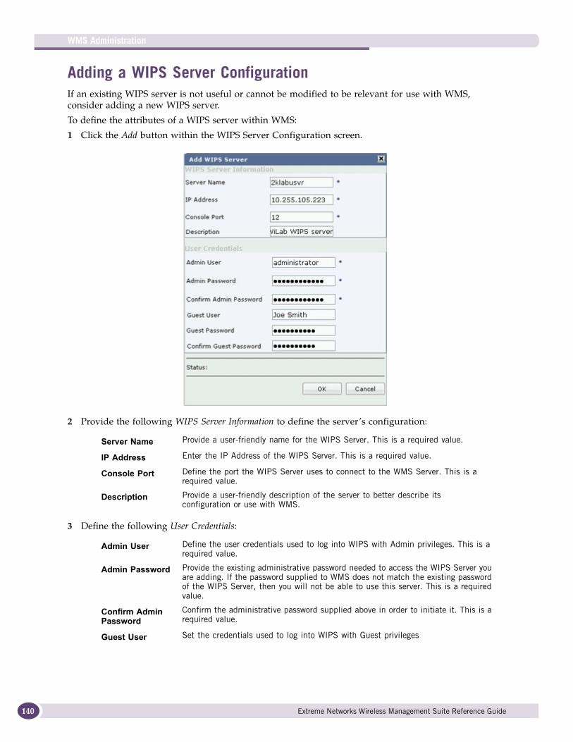
WMS Administration
140
Adding a WIPS Server ConfigurationIf an existing WIPS server is not useful or cannot be modified to be relevant for use with WMS, consider adding a new WIPS server.
To define the attributes of a WIPS server within WMS:
1 Click the Add button within the WIPS Server Configuration screen.
2 Provide the following WIPS Server Information to define the server’s configuration:
3 Define the following User Credentials:
Server Name Provide a user-friendly name for the WIPS Server. This is a required value.
IP Address Enter the IP Address of the WIPS Server. This is a required value.
Console Port Define the port the WIPS Server uses to connect to the WMS Server. This is a required value.
Description Provide a user-friendly description of the server to better describe its configuration or use with WMS.
Admin User Define the user credentials used to log into WIPS with Admin privileges. This is a required value.
Admin Password Provide the existing administrative password needed to access the WIPS Server you are adding. If the password supplied to WMS does not match the existing password of the WIPS Server, then you will not be able to use this server. This is a required value.
Confirm Admin Password
Confirm the administrative password supplied above in order to initiate it. This is a required value.
Guest User Set the credentials used to log into WIPS with Guest privileges
Extreme Networks Wireless Management Suite Reference Guide
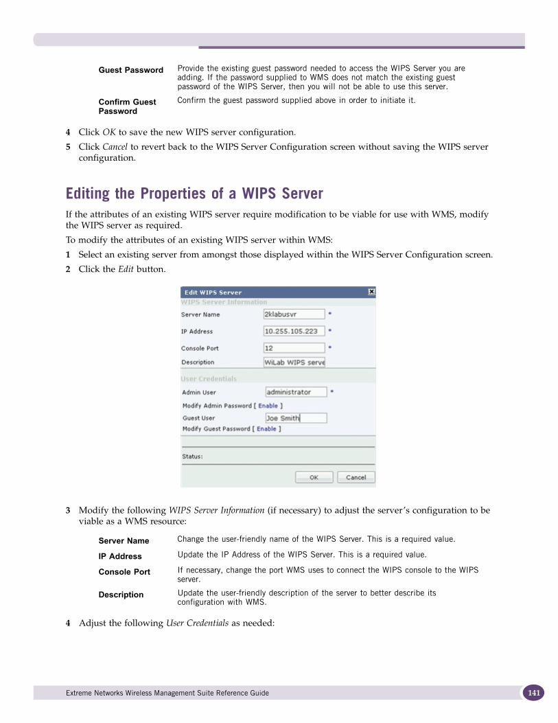
4 Click OK to save the new WIPS server configuration.
5 Click Cancel to revert back to the WIPS Server Configuration screen without saving the WIPS server configuration.
Editing the Properties of a WIPS ServerIf the attributes of an existing WIPS server require modification to be viable for use with WMS, modify the WIPS server as required.
To modify the attributes of an existing WIPS server within WMS:
1 Select an existing server from amongst those displayed within the WIPS Server Configuration screen.
2 Click the Edit button.
3 Modify the following WIPS Server Information (if necessary) to adjust the server’s configuration to be viable as a WMS resource:
4 Adjust the following User Credentials as needed:
Guest Password Provide the existing guest password needed to access the WIPS Server you are adding. If the password supplied to WMS does not match the existing guest password of the WIPS Server, then you will not be able to use this server.
Confirm Guest Password
Confirm the guest password supplied above in order to initiate it.
Server Name Change the user-friendly name of the WIPS Server. This is a required value.
IP Address Update the IP Address of the WIPS Server. This is a required value.
Console Port If necessary, change the port WMS uses to connect the WIPS console to the WIPS server.
Description Update the user-friendly description of the server to better describe its configuration with WMS.
Extreme Networks Wireless Management Suite Reference Guide 141
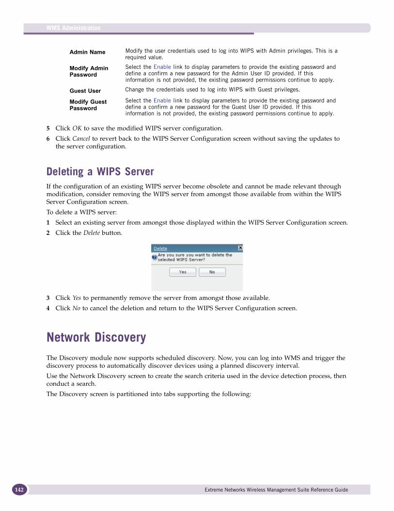
WMS Administration
142
5 Click OK to save the modified WIPS server configuration.
6 Click Cancel to revert back to the WIPS Server Configuration screen without saving the updates to the server configuration.
Deleting a WIPS ServerIf the configuration of an existing WIPS server become obsolete and cannot be made relevant through modification, consider removing the WIPS server from amongst those available from within the WIPS Server Configuration screen.
To delete a WIPS server:
1 Select an existing server from amongst those displayed within the WIPS Server Configuration screen.
2 Click the Delete button.
3 Click Yes to permanently remove the server from amongst those available.
4 Click No to cancel the deletion and return to the WIPS Server Configuration screen.
Network DiscoveryThe Discovery module now supports scheduled discovery. Now, you can log into WMS and trigger the discovery process to automatically discover devices using a planned discovery interval.
Use the Network Discovery screen to create the search criteria used in the device detection process, then conduct a search.
The Discovery screen is partitioned into tabs supporting the following:
Admin Name Modify the user credentials used to log into WIPS with Admin privileges. This is a required value.
Modify Admin Password
Select the Enable link to display parameters to provide the existing password and define a confirm a new password for the Admin User ID provided. If this information is not provided, the existing password permissions continue to apply.
Guest User Change the credentials used to log into WIPS with Guest privileges.
Modify Guest Password
Select the Enable link to display parameters to provide the existing password and define a confirm a new password for the Guest User ID provided. If this information is not provided, the existing password permissions continue to apply.
Extreme Networks Wireless Management Suite Reference Guide
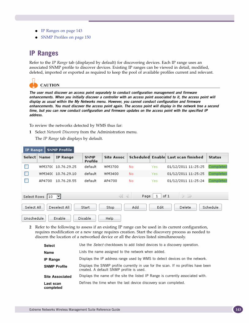
● IP Ranges on page 143
● SNMP Profiles on page 150
IP RangesRefer to the IP Range tab (displayed by default) for discovering devices. Each IP range uses an associated SNMP profile to discover devices. Existing IP ranges can be viewed in detail, modified, deleted, imported or exported as required to keep the pool of available profiles current and relevant.
CAUTION
The user must discover an access point separately to conduct configuration management and firmware enhancements. When you initially discover a controller with an access point associated to it, the access point will display as usual within the My Networks menu. However, you cannot conduct configuration and firmware enhancements. You must discover the access point again. The access point will display in the network tree a second time, but you can now conduct configuration and firmware updates on the access point with the specified IP address.
To review the networks detected by WMS thus far:
1 Select Network Discovery from the Administration menu.
The IP Range tab displays by default.
2 Refer to the following to assess if an existing IP range can be used in its current configuration, requires modification or a new range requires creation. Start the discovery process as needed to discern the location of a networked device or all the devices listed simultaneously.
Select Use the Select checkboxes to add listed devices to a discovery operation.
Name Lists the name assigned to the network when added.
IP Range Displays the IP address range used by WMS to detect devices on the network.
SNMP Profile Displays the SNMP profile currently in use for the scan. If no profiles have been created. A default SNMP profile is used.
Site Associated Displays the name of the site the listed IP Range is currently associated with.
Last scan completed
Defines the time when the last device discovery scan completed.
Extreme Networks Wireless Management Suite Reference Guide 143
WMS Administration
144
3 Once reviewed, consider any of the following discovery actions as required:
● Starting Network Discovery on page 144
● Stopping the Discovery Process on page 144
● Adding an IP Range on page 145
● Editing an IP Range on page 147
● Deleting an IP Range on page 149
● Scheduling a Discovery on page 149
Starting Network DiscoveryTo start the discovery process:
1 Select an IP range from amongst those displayed within the IP Range tab.
Optionally use the Select All option to select and begin the discovery process on each of the ranges displayed.
2 Click the Start button.
If you selected multiple devices or used the Select All option, the detection process will commence for one device at a time as listed from top to bottom within the IP Range tab.
Refer to the Status column (within the IP Range tab) to assess the completion of the device detection process. The Status column will update to “Completed” when the device detection process has completed.
3 Refer to the Devices column to review the number of devices detected for the site using the criteria you provided.
4 Refine your search criteria as needed to improve the search.
Stopping the Discovery ProcessThe network detection process can be terminated (once begun and in progress).
CAUTION
If the SNMP V3 timeout and retries intervals are increased (above their default values), it will take longer to stop the discovery process. If the SNMP v3 discovery process fails, WMS will attempt the discovery using SNMP v2.
To stop a network detection process:
1 Select an IP range from amongst those displayed within the IP Range tab.
Optionally use the Select All option to select each IP range.
2 Click the Stop button.
Schedule Displays whether each IP Range is currently scheduled to commence. Jobs that display No will not be run until enabled.
Enable Displays whether each IP Range is currently enabled.
Status Displays the status of the discovery process.
Devices Lists the number of devices detected for the site using the criteria you provided in the IP Range.
Extreme Networks Wireless Management Suite Reference Guide
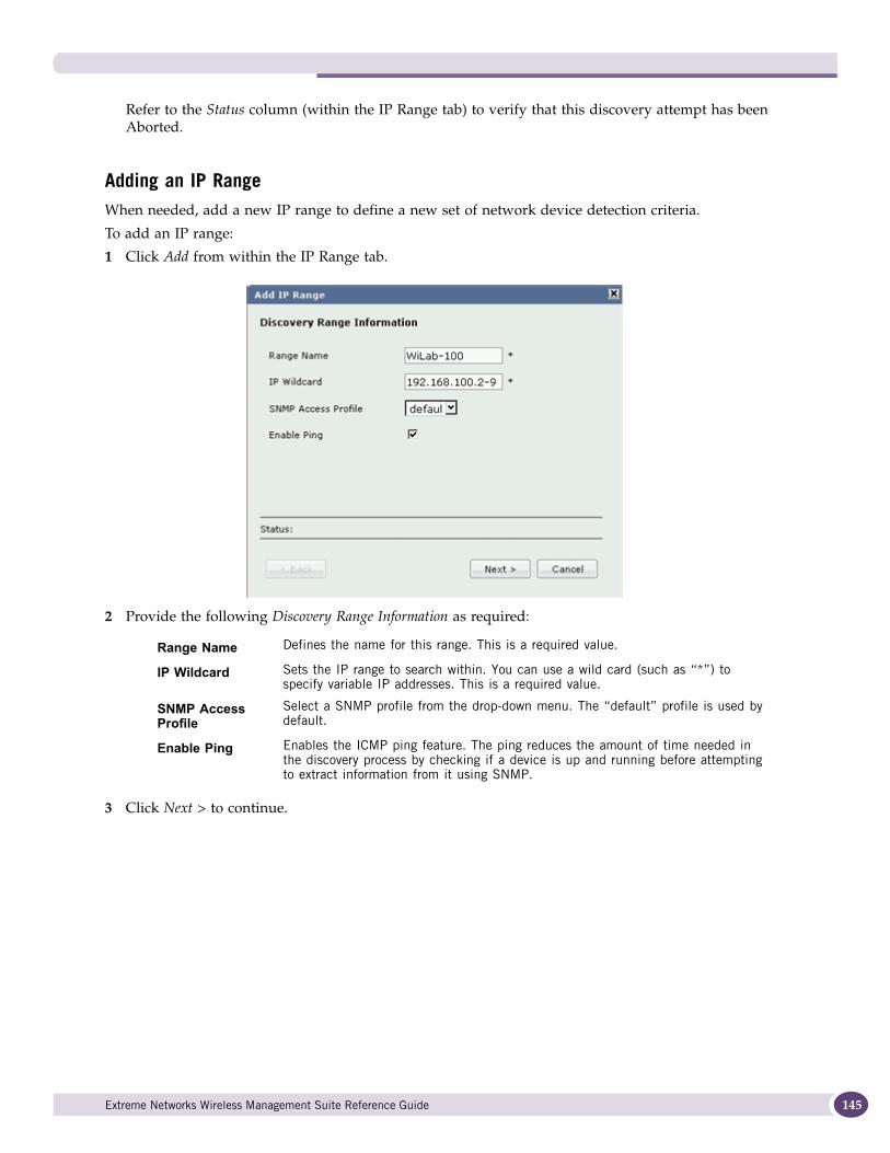
Refer to the Status column (within the IP Range tab) to verify that this discovery attempt has been Aborted.
Adding an IP RangeWhen needed, add a new IP range to define a new set of network device detection criteria.
To add an IP range:
1 Click Add from within the IP Range tab.
2 Provide the following Discovery Range Information as required:
3 Click Next > to continue.
Range Name Defines the name for this range. This is a required value.
IP Wildcard Sets the IP range to search within. You can use a wild card (such as “*”) to specify variable IP addresses. This is a required value.
SNMP Access Profile
Select a SNMP profile from the drop-down menu. The “default” profile is used by default.
Enable Ping Enables the ICMP ping feature. The ping reduces the amount of time needed in the discovery process by checking if a device is up and running before attempting to extract information from it using SNMP.
Extreme Networks Wireless Management Suite Reference Guide 145
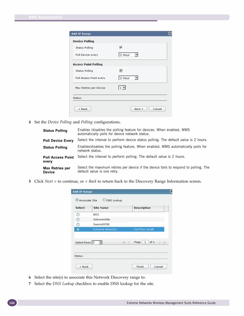
WMS Administration
146
4 Set the Device Polling and Polling configurations.
5 Click Next > to continue, or < Back to return back to the Discovery Range Information screen.
6 Select the site(s) to associate this Network Discovery range to.
7 Select the DNS Lookup checkbox to enable DNS lookup for the site.
Status Polling Enables /disables the polling feature for devices. When enabled, WMS automatically polls for device network status.
Poll Device Every Select the interval to perform device status polling. The default value is 2 hours.
Status Polling Enables/disables the polling feature. When enabled, WMS automatically polls for network status.
Poll Access Point every
Select the interval to perform polling. The default value is 2 hours.
Max Retries per Device
Select the maximum retries per device if the device fails to respond to polling. The default value is one retry.
Extreme Networks Wireless Management Suite Reference Guide
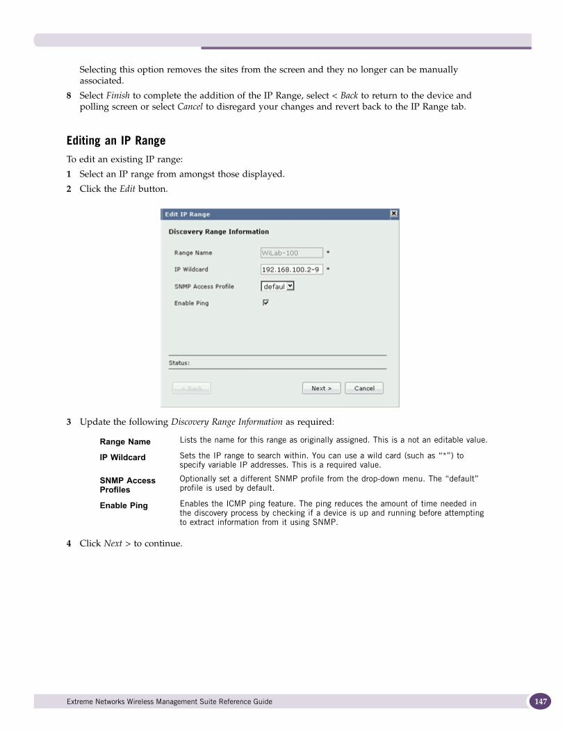
Selecting this option removes the sites from the screen and they no longer can be manually associated.
8 Select Finish to complete the addition of the IP Range, select < Back to return to the device and polling screen or select Cancel to disregard your changes and revert back to the IP Range tab.
Editing an IP RangeTo edit an existing IP range:
1 Select an IP range from amongst those displayed.
2 Click the Edit button.
3 Update the following Discovery Range Information as required:
4 Click Next > to continue.
Range Name Lists the name for this range as originally assigned. This is a not an editable value.
IP Wildcard Sets the IP range to search within. You can use a wild card (such as “*”) to specify variable IP addresses. This is a required value.
SNMP Access Profiles
Optionally set a different SNMP profile from the drop-down menu. The “default” profile is used by default.
Enable Ping Enables the ICMP ping feature. The ping reduces the amount of time needed in the discovery process by checking if a device is up and running before attempting to extract information from it using SNMP.
Extreme Networks Wireless Management Suite Reference Guide 147
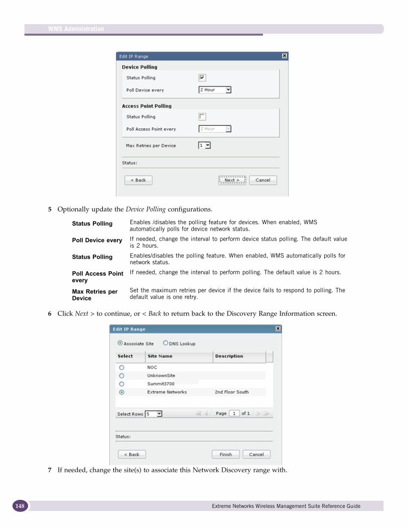
WMS Administration
148
5 Optionally update the Device Polling configurations.
6 Click Next > to continue, or < Back to return back to the Discovery Range Information screen.
7 If needed, change the site(s) to associate this Network Discovery range with.
Status Polling Enables /disables the polling feature for devices. When enabled, WMS automatically polls for device network status.
Poll Device every If needed, change the interval to perform device status polling. The default value is 2 hours.
Status Polling Enables/disables the polling feature. When enabled, WMS automatically polls for network status.
Poll Access Point every
If needed, change the interval to perform polling. The default value is 2 hours.
Max Retries per Device
Set the maximum retries per device if the device fails to respond to polling. The default value is one retry.
Extreme Networks Wireless Management Suite Reference Guide
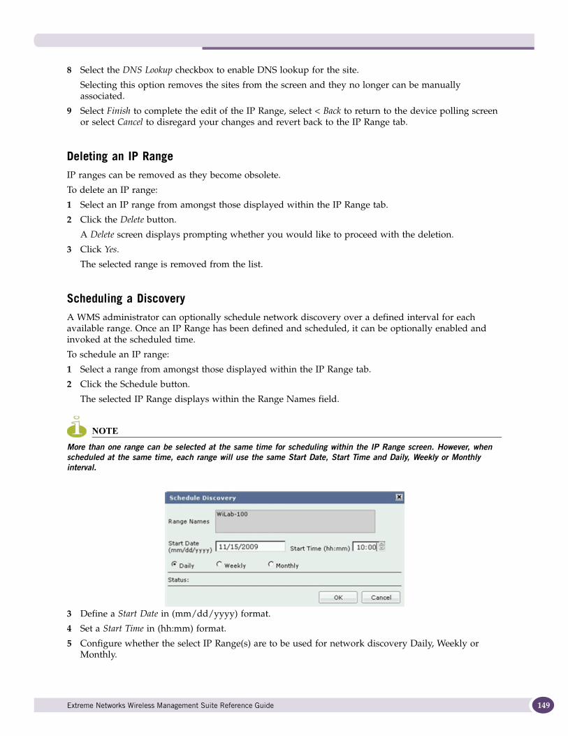
8 Select the DNS Lookup checkbox to enable DNS lookup for the site.
Selecting this option removes the sites from the screen and they no longer can be manually associated.
9 Select Finish to complete the edit of the IP Range, select < Back to return to the device polling screen or select Cancel to disregard your changes and revert back to the IP Range tab.
Deleting an IP RangeIP ranges can be removed as they become obsolete.
To delete an IP range:
1 Select an IP range from amongst those displayed within the IP Range tab.
2 Click the Delete button.
A Delete screen displays prompting whether you would like to proceed with the deletion.
3 Click Yes.
The selected range is removed from the list.
Scheduling a DiscoveryA WMS administrator can optionally schedule network discovery over a defined interval for each available range. Once an IP Range has been defined and scheduled, it can be optionally enabled and invoked at the scheduled time.
To schedule an IP range:
1 Select a range from amongst those displayed within the IP Range tab.
2 Click the Schedule button.
The selected IP Range displays within the Range Names field.
NOTE
More than one range can be selected at the same time for scheduling within the IP Range screen. However, when scheduled at the same time, each range will use the same Start Date, Start Time and Daily, Weekly or Monthly interval.
3 Define a Start Date in (mm/dd/yyyy) format.
4 Set a Start Time in (hh:mm) format.
5 Configure whether the select IP Range(s) are to be used for network discovery Daily, Weekly or Monthly.
Extreme Networks Wireless Management Suite Reference Guide 149
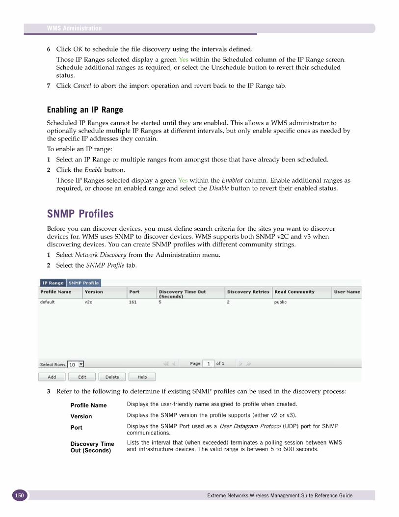
WMS Administration
150
6 Click OK to schedule the file discovery using the intervals defined.
Those IP Ranges selected display a green Yes within the Scheduled column of the IP Range screen. Schedule additional ranges as required, or select the Unschedule button to revert their scheduled status.
7 Click Cancel to abort the import operation and revert back to the IP Range tab.
Enabling an IP RangeScheduled IP Ranges cannot be started until they are enabled. This allows a WMS administrator to optionally schedule multiple IP Ranges at different intervals, but only enable specific ones as needed by the specific IP addresses they contain.
To enable an IP range:
1 Select an IP Range or multiple ranges from amongst those that have already been scheduled.
2 Click the Enable button.
Those IP Ranges selected display a green Yes within the Enabled column. Enable additional ranges as required, or choose an enabled range and select the Disable button to revert their enabled status.
SNMP ProfilesBefore you can discover devices, you must define search criteria for the sites you want to discover devices for. WMS uses SNMP to discover devices. WMS supports both SNMP v2C and v3 when discovering devices. You can create SNMP profiles with different community strings.
1 Select Network Discovery from the Administration menu.
2 Select the SNMP Profile tab.
3 Refer to the following to determine if existing SNMP profiles can be used in the discovery process:
Profile Name Displays the user-friendly name assigned to profile when created.
Version Displays the SNMP version the profile supports (either v2 or v3).
Port Displays the SNMP Port used as a User Datagram Protocol (UDP) port for SNMP communications.
Discovery Time Out (Seconds)
Lists the interval that (when exceeded) terminates a polling session between WMS and infrastructure devices. The valid range is between 5 to 600 seconds.
Extreme Networks Wireless Management Suite Reference Guide
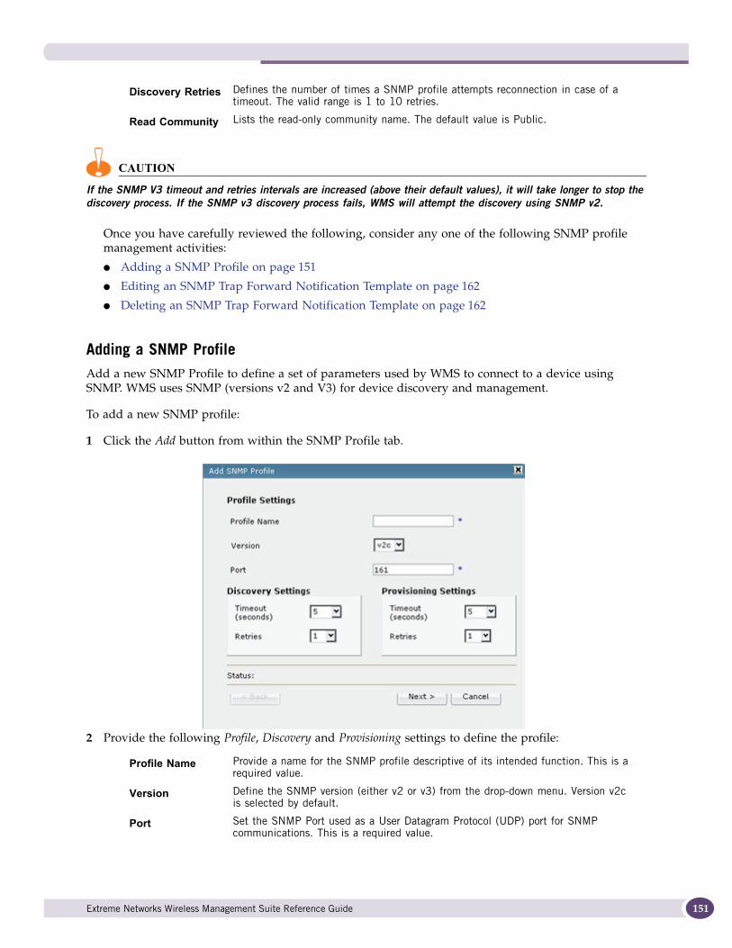
CAUTION
If the SNMP V3 timeout and retries intervals are increased (above their default values), it will take longer to stop the discovery process. If the SNMP v3 discovery process fails, WMS will attempt the discovery using SNMP v2.
Once you have carefully reviewed the following, consider any one of the following SNMP profile management activities:
● Adding a SNMP Profile on page 151
● Editing an SNMP Trap Forward Notification Template on page 162
● Deleting an SNMP Trap Forward Notification Template on page 162
Adding a SNMP ProfileAdd a new SNMP Profile to define a set of parameters used by WMS to connect to a device using SNMP. WMS uses SNMP (versions v2 and V3) for device discovery and management.
To add a new SNMP profile:
1 Click the Add button from within the SNMP Profile tab.
2 Provide the following Profile, Discovery and Provisioning settings to define the profile:
Discovery Retries Defines the number of times a SNMP profile attempts reconnection in case of a timeout. The valid range is 1 to 10 retries.
Read Community Lists the read-only community name. The default value is Public.
Profile Name Provide a name for the SNMP profile descriptive of its intended function. This is a required value.
Version Define the SNMP version (either v2 or v3) from the drop-down menu. Version v2c is selected by default.
Port Set the SNMP Port used as a User Datagram Protocol (UDP) port for SNMP communications. This is a required value.
Extreme Networks Wireless Management Suite Reference Guide 151
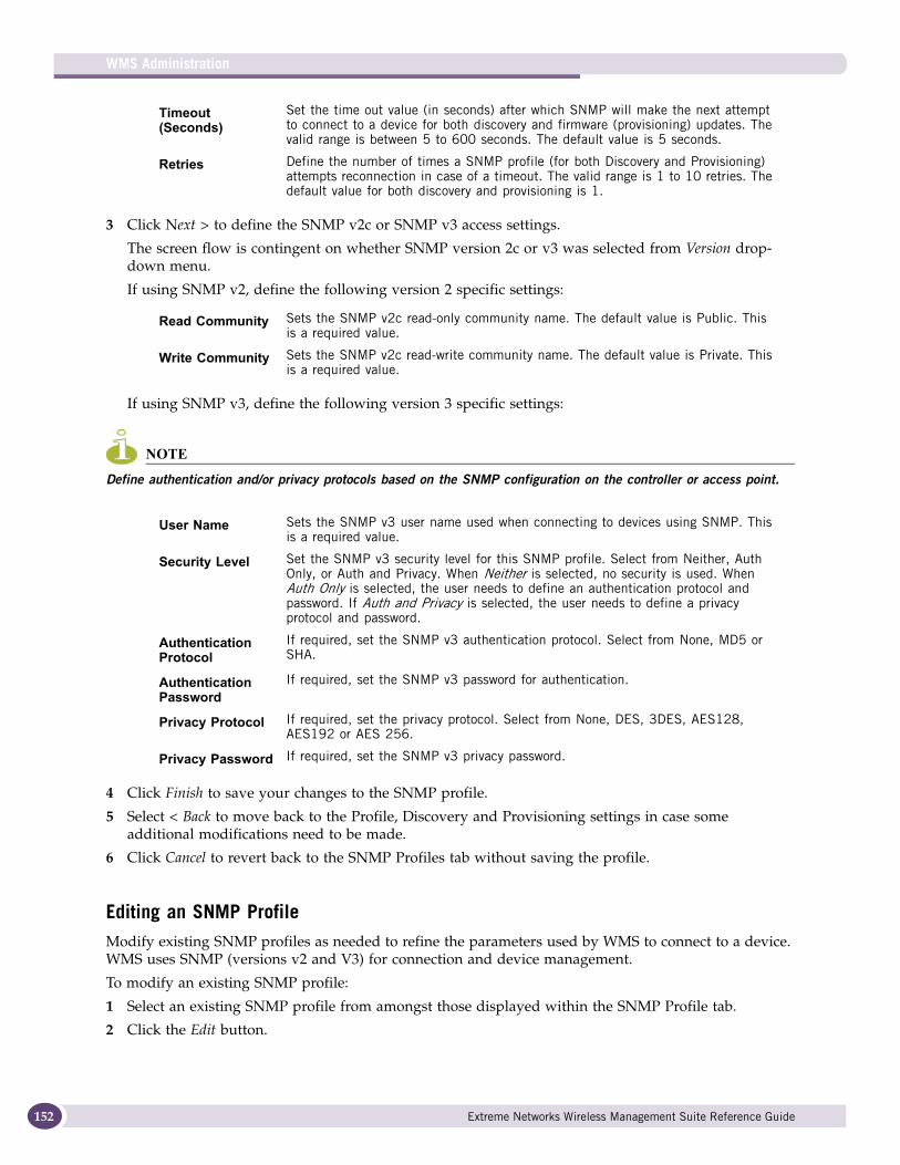
WMS Administration
152
3 Click Next > to define the SNMP v2c or SNMP v3 access settings.
The screen flow is contingent on whether SNMP version 2c or v3 was selected from Version drop-down menu.
If using SNMP v2, define the following version 2 specific settings:
If using SNMP v3, define the following version 3 specific settings:
NOTE
Define authentication and/or privacy protocols based on the SNMP configuration on the controller or access point.
4 Click Finish to save your changes to the SNMP profile.
5 Select < Back to move back to the Profile, Discovery and Provisioning settings in case some additional modifications need to be made.
6 Click Cancel to revert back to the SNMP Profiles tab without saving the profile.
Editing an SNMP ProfileModify existing SNMP profiles as needed to refine the parameters used by WMS to connect to a device. WMS uses SNMP (versions v2 and V3) for connection and device management.
To modify an existing SNMP profile:
1 Select an existing SNMP profile from amongst those displayed within the SNMP Profile tab.
2 Click the Edit button.
Timeout (Seconds)
Set the time out value (in seconds) after which SNMP will make the next attempt to connect to a device for both discovery and firmware (provisioning) updates. The valid range is between 5 to 600 seconds. The default value is 5 seconds.
Retries Define the number of times a SNMP profile (for both Discovery and Provisioning) attempts reconnection in case of a timeout. The valid range is 1 to 10 retries. The default value for both discovery and provisioning is 1.
Read Community Sets the SNMP v2c read-only community name. The default value is Public. This is a required value.
Write Community Sets the SNMP v2c read-write community name. The default value is Private. This is a required value.
User Name Sets the SNMP v3 user name used when connecting to devices using SNMP. This is a required value.
Security Level Set the SNMP v3 security level for this SNMP profile. Select from Neither, Auth Only, or Auth and Privacy. When Neither is selected, no security is used. When Auth Only is selected, the user needs to define an authentication protocol and password. If Auth and Privacy is selected, the user needs to define a privacy protocol and password.
Authentication Protocol
If required, set the SNMP v3 authentication protocol. Select from None, MD5 or SHA.
Authentication Password
If required, set the SNMP v3 password for authentication.
Privacy Protocol If required, set the privacy protocol. Select from None, DES, 3DES, AES128, AES192 or AES 256.
Privacy Password If required, set the SNMP v3 privacy password.
Extreme Networks Wireless Management Suite Reference Guide
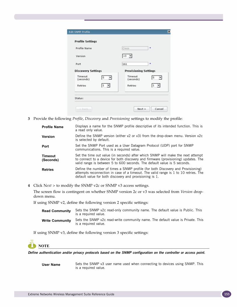
3 Provide the following Profile, Discovery and Provisioning settings to modify the profile:
4 Click Next > to modify the SNMP v2c or SNMP v3 access settings.
The screen flow is contingent on whether SNMP version 2c or v3 was selected from Version drop-down menu.
If using SNMP v2, define the following version 2 specific settings:
If using SNMP v3, define the following version 3 specific settings:
NOTE
Define authentication and/or privacy protocols based on the SNMP configuration on the controller or access point.
Profile Name Displays a name for the SNMP profile descriptive of its intended function. This is a read only value.
Version Define the SNMP version (either v2 or v3) from the drop-down menu. Version v2c is selected by default.
Port Set the SNMP Port used as a User Datagram Protocol (UDP) port for SNMP communications. This is a required value.
Timeout (Seconds)
Set the time out value (in seconds) after which SNMP will make the next attempt to connect to a device for both discovery and firmware (provisioning) updates. The valid range is between 5 to 600 seconds. The default value is 5 seconds.
Retries Define the number of times a SNMP profile (for both Discovery and Provisioning) attempts reconnection in case of a timeout. The valid range is 1 to 10 retries. The default value for both discovery and provisioning is 1.
Read Community Sets the SNMP v2c read-only community name. The default value is Public. This is a required value.
Write Community Sets the SNMP v2c read-write community name. The default value is Private. This is a required value.
User Name Sets the SNMP v3 user name used when connecting to devices using SNMP. This is a required value.
Extreme Networks Wireless Management Suite Reference Guide 153
WMS Administration
154
5 Click Finish to save your updates to this existing SNMP profile.
6 Select < Back to move back to the Profile, Discovery and Provisioning settings in case some additional modifications need to be made.
7 Click Cancel to revert back to the SNMP Profiles tab without saving the profile.
Deleting an SNMP ProfileWhen SNMP profiles become obsolete, they can be removed from the list of those available within the SNMP Profile tab.
To delete an SNMP profile:
1 Select an existing profile from amongst those available within the SNMP Profiles tab.
2 Click the Delete button.
A Delete confirmation screen displays.
3 Click Yes.
The selected SNMP profile is removed from the list.
Network MonitoringUse the Network Monitoring screen to monitor devices within sites managed by WMS. The Network Monitoring uses a SNMP browser interface to manage the individual properties of devices. Each device model has an associated data collection profile which identifies the list of attributes collected periodically from the device.
To review devices detected within the WMS managed network:
Security Level Set the SNMP v3 security level for this SNMP profile. Select from Neither, Auth Only, or Auth and Privacy. When Neither is selected, no security is used. When Auth Only is selected, the user needs to define an authentication protocol and password. If Auth and Privacy is selected, the user needs to define a privacy protocol and password.
Authentication Protocol
If required, set the SNMP v3 authentication protocol. Select from None, MD5 or SHA.
Authentication Password
If required, set the SNMP v3 password for authentication.
Privacy Protocol If required, set the privacy protocol. Select from None, DES, 3DES, AES128, AES192 or AES 256.
Privacy Password If required, set the SNMP v3 privacy password.
Extreme Networks Wireless Management Suite Reference Guide
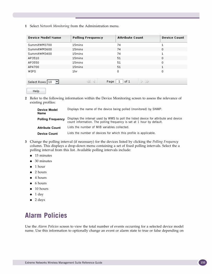
1 Select Network Monitoring from the Administration menu.
2 Refer to the following information within the Device Monitoring screen to assess the relevance of existing profiles:
3 Change the polling interval (if necessary) for the devices listed by clicking the Polling Frequency column. This displays a drop-down menu containing a set of fixed polling intervals. Select the a polling interval from this list. Available polling intervals include:
● 15 minutes
● 30 minutes
● 1 hour
● 2 hours
● 4 hours
● 6 hours
● 10 hours
● 1 day
● 2 days
Alarm PoliciesUse the Alarm Policies screen to view the total number of events occurring for a selected device model name. Use this information to optionally change an event or alarm state to true or false depending on
Device Model Name
Displays the name of the device being polled (monitored) by SNMP.
Polling Frequency Displays the interval used by WMS to poll the listed device for attribute and device count information. The polling frequency is set at 1 hour by default.
Attribute Count Lists the number of MIB variables collected.
Device Count Lists the number of devices for which this profile is applicable.
Extreme Networks Wireless Management Suite Reference Guide 155
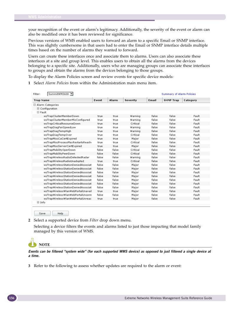
WMS Administration
156
your recognition of the event or alarm’s legitimacy. Additionally, the severity of the event or alarm can also be modified once it has been reviewed for significance.
Previous versions of WMS enabled users to forward an alarm to a specific Email or SNMP interface. This was slightly cumbersome in that users had to enter the Email or SNMP interface details multiple times based on the number of alarms they wanted to forward.
Users can create these interfaces once and associate them to alarms. Users can also associate these interfaces at a site and group level. This enables users to obtain all the alarms from the devices belonging to a specific site. Additionally, users who are managing groups can associate these interfaces to groups and obtain the alarms from the devices belonging to those groups.
To display the Alarm Policies screen and review events for specific device models:
1 Select Alarm Policies from within the Administration main menu item.
2 Select a supported device from Filter drop down menu.
Selecting a device filters the events and alarms listed to just those impacting that model family managed by this version of WMS.
NOTE
Events can be filtered “system wide” (for each supported WMS device) as opposed to just filtered a single device at a time.
3 Refer to the following to assess whether updates are required to the alarm or event:
Extreme Networks Wireless Management Suite Reference Guide
4 If modifications have been made to the event or alarm’s legitimacy, severity, email/SNMP status or category, click the Save button.
A Save Alarm Policies screen displays stating the modifications have been successfully updated. Click OK to close this pop-up screen.
5 At any time during your alarm policy review, select the Summary of Alarm Policies link at the top of the Alarm Policies screen to display a high-level summary of the number of traps, events, alarms and associated devices for each WMS supported device model.
Notification TemplatesNotification templates allow a single policy to be create for multiple events The WMS administrator can view, add, modify, delete, and define Email and SNMP notification templates. When an error occurs on a WMS managed device, the information is submitted to an administrator through a WMS defined Email address. WMS uses notification templates to convey this information. Additionally, SNMP traps can be forwarded to upstream network management systems on any event reported in the WMS console. These destinations are configured by selecting the SNMP Trap Forward tab and creating a trap forward destination IP address and defining SNMP version parameters.
Trap Name Use the Alarm Categories option to expand and select and list those alarm categories for the selected device. Alarm Categories include Configuration, Fault, Info, Performance, Security and Standard. Expand any one of these categories to display the trap name that (once violated) displays the listed event or alarm. Remember, each WMS supported device has its own set of SNMP traps and subsequent events and alarms.
Event Any trap with a true designation has the event data reported outside of WMS. Change the designation to false to keep this information resident to WMS and prohibit it from going to the reporting device interface.
Alarm Any trap with a true designation has the alarm data reported outside of WMS. Change the designation to false to keep this information resident to WMS and prohibit it from going to the reporting device interface.
Severity Displays the Critical, Major, Minor, Warning or Info designation associated with this listed trap. Optionally select the category from the screen to display a drop-down menu used to change the category if a re-classification is required.
Email Any trap with a true designation has the trap violation data sent to the Email template recipient you have created in WMS. Change the designation to false to keep this information resident to WMS and prohibit it from going out via Email.
SNMP Trap Any trap with a true designation has the trap violation data sent to the SNMP management server. Change the designation to false to keep this information resident to WMS and prohibit it from going to the SNMP management server.
Category Displays the Configuration, Fault, Performance, Security, Standard, or Info category associated with this listed trap. Optionally select the category from the screen to display a drop-down menu used to change the category if a re-classification is required.
Extreme Networks Wireless Management Suite Reference Guide 157
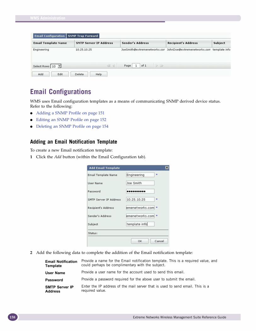
WMS Administration
158
Email ConfigurationsWMS uses Email configuration templates as a means of communicating SNMP derived device status. Refer to the following:
● Adding a SNMP Profile on page 151
● Editing an SNMP Profile on page 152
● Deleting an SNMP Profile on page 154
Adding an Email Notification TemplateTo create a new Email notification template:
1 Click the Add button (within the Email Configuration tab).
2 Add the following data to complete the addition of the Email notification template:
Email Notification Template
Provide a name for the Email notification template. This is a required value, and could perhaps be complimentary with the subject.
User Name Provide a user name for the account used to send this email.
Password Provide a password required for the above user to submit the email.
SMTP Server IP Address
Enter the IP address of the mail server that is used to send email. This is a required value.
Extreme Networks Wireless Management Suite Reference Guide
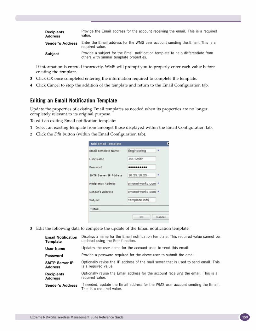
If information is entered incorrectly, WMS will prompt you to properly enter each value before creating the template.
3 Click OK once completed entering the information required to complete the template.
4 Click Cancel to stop the addition of the template and return to the Email Configuration tab.
Editing an Email Notification TemplateUpdate the properties of existing Email templates as needed when its properties are no longer completely relevant to its original purpose.
To edit an exiting Email notification template:
1 Select an existing template from amongst those displayed within the Email Configuration tab.
2 Click the Edit button (within the Email Configuration tab).
3 Edit the following data to complete the update of the Email notification template:
Recipients Address
Provide the Email address for the account receiving the email. This is a required value.
Sender’s Address Enter the Email address for the WMS user account sending the Email. This is a required value.
Subject Provide a subject for the Email notification template to help differentiate from others with similar template properties.
Email Notification Template
Displays a name for the Email notification template. This required value cannot be updated using the Edit function.
User Name Updates the user name for the account used to send this email.
Password Provide a password required for the above user to submit the email.
SMTP Server IP Address
Optionally revise the IP address of the mail server that is used to send email. This is a required value.
Recipients Address
Optionally revise the Email address for the account receiving the email. This is a required value.
Sender’s Address If needed, update the Email address for the WMS user account sending the Email. This is a required value.
Extreme Networks Wireless Management Suite Reference Guide 159
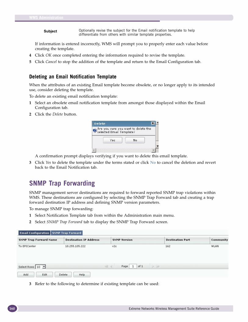
WMS Administration
160
If information is entered incorrectly, WMS will prompt you to properly enter each value before creating the template.
4 Click OK once completed entering the information required to revise the template.
5 Click Cancel to stop the addition of the template and return to the Email Configuration tab.
Deleting an Email Notification TemplateWhen the attributes of an existing Email template become obsolete, or no longer apply to its intended use, consider deleting the template.
To delete an existing email notification template:
1 Select an obsolete email notification template from amongst those displayed within the Email Configuration tab.
2 Click the Delete button.
A confirmation prompt displays verifying if you want to delete this email template.
3 Click Yes to delete the template under the terms stated or click No to cancel the deletion and revert back to the Email Notification tab.
SNMP Trap ForwardingSNMP management server destinations are required to forward reported SNMP trap violations within WMS. These destinations are configured by selecting the SNMP Trap Forward tab and creating a trap forward destination IP address and defining SNMP version parameters.
To manage SNMP trap forwarding:
1 Select Notification Template tab from within the Administration main menu.
2 Select SNMP Trap Forward tab to display the SNMP Trap Forward screen.
3 Refer to the following to determine if existing template can be used:
Subject Optionally revise the subject for the Email notification template to help differentiate from others with similar template properties.
Extreme Networks Wireless Management Suite Reference Guide
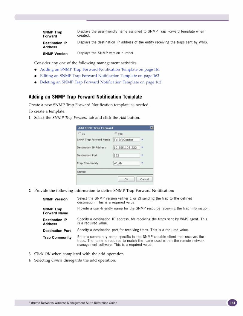
Consider any one of the following management activities:
● Adding an SNMP Trap Forward Notification Template on page 161
● Editing an SNMP Trap Forward Notification Template on page 162
● Deleting an SNMP Trap Forward Notification Template on page 162
Adding an SNMP Trap Forward Notification TemplateCreate a new SNMP Trap Forward Notification template as needed.
To create a template:
1 Select the SNMP Trap Forward tab and click the Add button.
2 Provide the following information to define SNMP Trap Forward Notification:
3 Click OK when completed with the add operation.
4 Selecting Cancel disregards the add operation.
SNMP Trap Forward
Displays the user-friendly name assigned to SNMP Trap Forward template when created.
Destination IP Address
Displays the destination IP address of the entity receiving the traps sent by WMS.
SNMP Version Displays the SNMP version number.
SNMP Version Select the SNMP version (either 1 or 2) sending the trap to the defined destination. This is a required value.
SNMP Trap Forward Name
Provide a user-friendly name for the SNMP resource receiving the trap information.
Destination IP Address
Specify a destination IP address, for receiving the traps sent by WMS agent. This is a required value.
Destination Port Specify a destination port for receiving traps. This is a required value.
Trap Community Enter a community name specific to the SNMP-capable client that receives the traps. The name is required to match the name used within the remote network management software. This is a required value.
Extreme Networks Wireless Management Suite Reference Guide 161
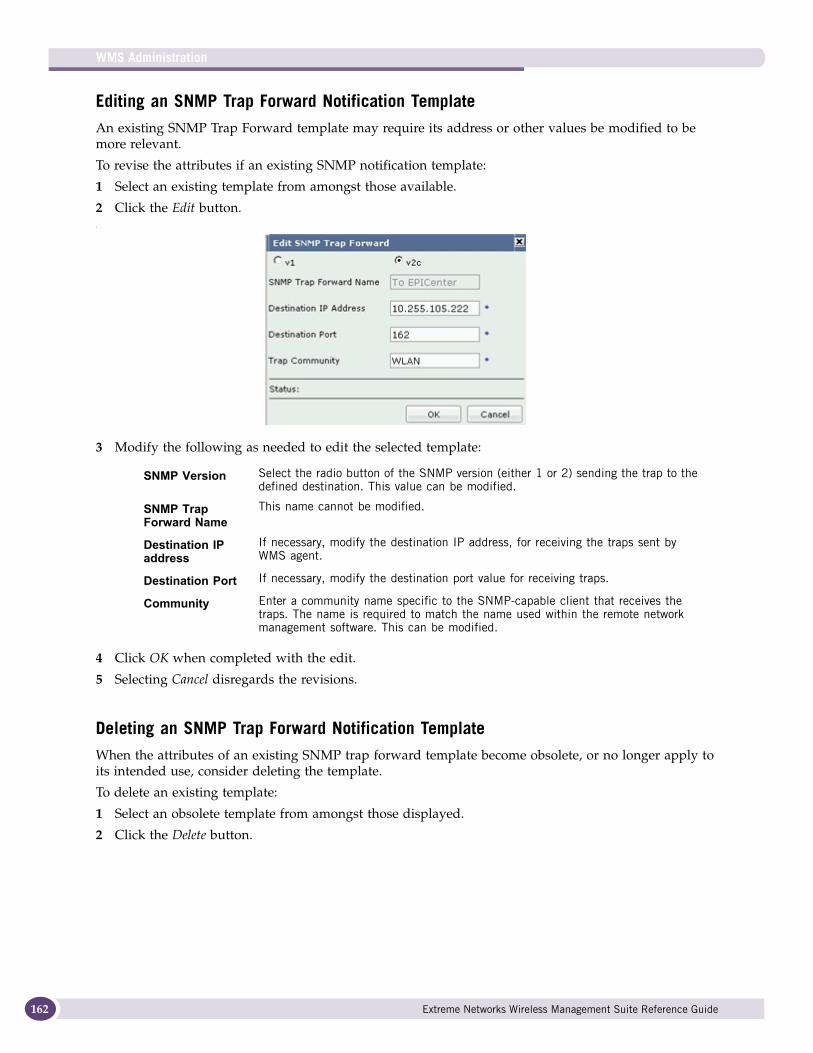
WMS Administration
162
Editing an SNMP Trap Forward Notification TemplateAn existing SNMP Trap Forward template may require its address or other values be modified to be more relevant.
To revise the attributes if an existing SNMP notification template:
1 Select an existing template from amongst those available.
2 Click the Edit button..
3 Modify the following as needed to edit the selected template:
4 Click OK when completed with the edit.
5 Selecting Cancel disregards the revisions.
Deleting an SNMP Trap Forward Notification TemplateWhen the attributes of an existing SNMP trap forward template become obsolete, or no longer apply to its intended use, consider deleting the template.
To delete an existing template:
1 Select an obsolete template from amongst those displayed.
2 Click the Delete button.
SNMP Version Select the radio button of the SNMP version (either 1 or 2) sending the trap to the defined destination. This value can be modified.
SNMP Trap Forward Name
This name cannot be modified.
Destination IP address
If necessary, modify the destination IP address, for receiving the traps sent by WMS agent.
Destination Port If necessary, modify the destination port value for receiving traps.
Community Enter a community name specific to the SNMP-capable client that receives the traps. The name is required to match the name used within the remote network management software. This can be modified.
Extreme Networks Wireless Management Suite Reference Guide
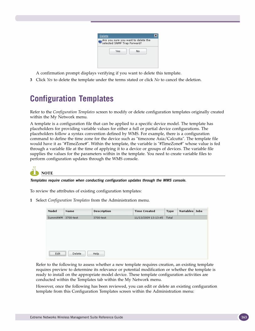
A confirmation prompt displays verifying if you want to delete this template.
3 Click Yes to delete the template under the terms stated or click No to cancel the deletion.
Configuration TemplatesRefer to the Configuration Templates screen to modify or delete configuration templates originally created within the My Network menu.
A template is a configuration file that can be applied to a specific device model. The template has placeholders for providing variable values for either a full or partial device configurations. The placeholders follow a syntax convention defined by WMS. For example, there is a configuration command to define the time zone for the device such as "timezone Asia/Calcutta". The template file would have it as "#TimeZone#". Within the template, the variable is "#TimeZone#" whose value is fed through a variable file at the time of applying it to a device or groups of devices. The variable file supplies the values for the parameters within in the template. You need to create variable files to perform configuration updates through the WMS console.
NOTE
Templates require creation when conducting configuration updates through the WMS console.
To review the attributes of existing configuration templates:
1 Select Configuration Templates from the Administration menu.
Refer to the following to assess whether a new template requires creation, an existing template requires preview to determine its relevance or potential modification or whether the template is ready to install on the appropriate model device. These template configuration activities are conducted within the Templates tab within the My Network menu.
However, once the following has been reviewed, you can edit or delete an existing configuration template from this Configuration Templates screen within the Administration menu:
Extreme Networks Wireless Management Suite Reference Guide 163
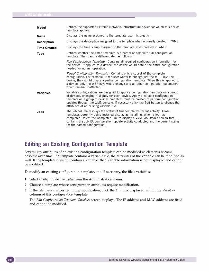
WMS Administration
164
Editing an Existing Configuration TemplateSeveral key attributes of an existing configuration template can be modified as elements become obsolete over time. If a template contains a variable file, the attributes of the variable can be modified as well. If the template does not contain a variable, then variable information is not displayed and cannot be modified.
To modify an existing configuration template, and if necessary, the file’s variables:
1 Select Configuration Templates from the Administration menu.
2 Choose a template whose configuration attributes require modification.
3 If the file has variables requiring modification, click the Edit link displayed within the Variables column of this configuration template.
The Edit Configuration Template Variables screen displays. The IP address and MAC address are fixed and cannot be modified.
Model Defines the supported Extreme Networks infrastructure device for which this device template applies.
Name Displays the name assigned to the template upon its creation.
Description Displays the description assigned to the template when originally created in WMS.
Time Created Displays the time stamp assigned to the template when created in WMS.
Type Defines whether the listed template is a partial or complete full configuration template. They can be differentiated as follows:
Full Configuration Template - Contains all required configuration information for the device. If applied to a device, the device would obtain the entire configuration needed for normal operation.
Partial Configuration Template - Contains only a subset of the complete configuration. For example, if the user wants to change just the WEP keys the device, they would create a partial configuration template. When this is applied to a device, only the WEP keys would change and all other configuration parameters would remain unaffected
Variables Variable configurations are designed to apply a configuration template on a group of devices, changing it slightly for each device. Apply a variable configuration template on a group of devices. Variables must be created to perform configuration updates through the WMS console. If necessary click the Edit button to change the attributes of an existing variable file.
Jobs The job column displays the status of this template’s recent activity. Those templates currently being installed display as installing. When a job has completed, select the Completed link to display a View Job Details screen that contains the Job ID, configuration update activity conducted and the current status for the named configuration.
Extreme Networks Wireless Management Suite Reference Guide
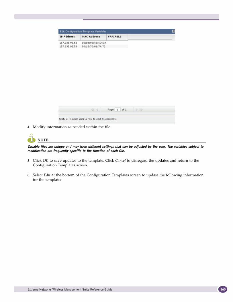
4 Modify information as needed within the file.
NOTE
Variable files are unique and may have different settings that can be adjusted by the user. The variables subject to modification are frequently specific to the function of each file.
5 Click OK to save updates to the template. Click Cancel to disregard the updates and return to the Configuration Templates screen.
6 Select Edit at the bottom of the Configuration Templates screen to update the following information for the template:
Extreme Networks Wireless Management Suite Reference Guide 165
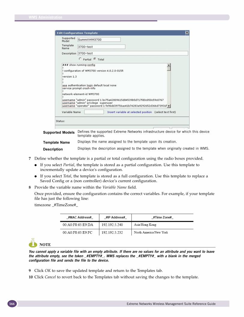
WMS Administration
166
7 Define whether the template is a partial or total configuration using the radio boxes provided.
● If you select Partial, the template is stored as a partial configuration. Use this template to incrementally update a device's configuration.
● If you select Total, the template is stored as a full configuration. Use this template to replace a Saved Config or a (non controller) device’s current configuration.
8 Provide the variable name within the Variable Name field.
Once provided, ensure the configuration contains the correct variables. For example, if your template file has just the following line:
timezone _#TimeZone#_
NOTE
You cannot apply a variable file with an empty attribute. If there are no values for an attribute and you want to leave the attribute empty, see the token _#EMPTY#_. WMS replaces the _#EMPTY#_ with a blank in the merged configuration file and sends the file to the device.
9 Click OK to save the updated template and return to the Templates tab.
10 Click Cancel to revert back to the Templates tab without saving the changes to the template.
Supported Models Defines the supported Extreme Networks infrastructure device for which this device template applies.
Template Name Displays the name assigned to the template upon its creation.
Description Displays the description assigned to the template when originally created in WMS.
Extreme Networks Wireless Management Suite Reference Guide
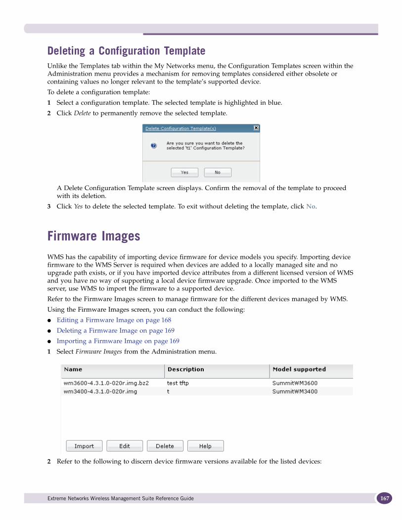
Deleting a Configuration TemplateUnlike the Templates tab within the My Networks menu, the Configuration Templates screen within the Administration menu provides a mechanism for removing templates considered either obsolete or containing values no longer relevant to the template’s supported device.
To delete a configuration template:
1 Select a configuration template. The selected template is highlighted in blue.
2 Click Delete to permanently remove the selected template.
A Delete Configuration Template screen displays. Confirm the removal of the template to proceed with its deletion.
3 Click Yes to delete the selected template. To exit without deleting the template, click No.
Firmware ImagesWMS has the capability of importing device firmware for device models you specify. Importing device firmware to the WMS Server is required when devices are added to a locally managed site and no upgrade path exists, or if you have imported device attributes from a different licensed version of WMS and you have no way of supporting a local device firmware upgrade. Once imported to the WMS server, use WMS to import the firmware to a supported device.
Refer to the Firmware Images screen to manage firmware for the different devices managed by WMS.
Using the Firmware Images screen, you can conduct the following:
● Editing a Firmware Image on page 168
● Deleting a Firmware Image on page 169
● Importing a Firmware Image on page 169
1 Select Firmware Images from the Administration menu.
2 Refer to the following to discern device firmware versions available for the listed devices:
Extreme Networks Wireless Management Suite Reference Guide 167
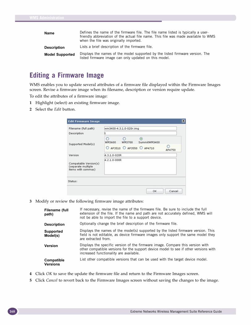
WMS Administration
168
Editing a Firmware ImageWMS enables you to update several attributes of a firmware file displayed within the Firmware Images screen. Revise a firmware image when its filename, description or version require update.
To edit the attributes of a firmware image:
1 Highlight (select) an existing firmware image.
2 Select the Edit button.
3 Modify or review the following firmware image attributes:
4 Click OK to save the update the firmware file and return to the Firmware Images screen.
5 Click Cancel to revert back to the Firmware Images screen without saving the changes to the image.
Name Defines the name of the firmware file. The file name listed is typically a user-friendly abbreviation of the actual file name. This file was made available to WMS when the file was originally imported.
Description Lists a brief description of the firmware file.
Model Supported Displays the names of the model supported by the listed firmware version. The listed firmware image can only updated on this model.
Filename (full path)
If necessary, revise the name of the firmware file. Be sure to include the full extension of the file. If the name and path are not accurately defined, WMS will not be able to import the file to a support device.
Description Optionally change the brief description of the firmware file.
Supported Model(s)
Displays the names of the model(s) supported by the listed firmware version. This field is not editable, as device firmware images only support the same model they are extracted from.
Version Displays the specific version of the firmware image. Compare this version with other compatible versions for the support device model to see if other versions with increased functionality are available.
Compatible Versions
List other compatible versions that can be used with the target device model.
Extreme Networks Wireless Management Suite Reference Guide
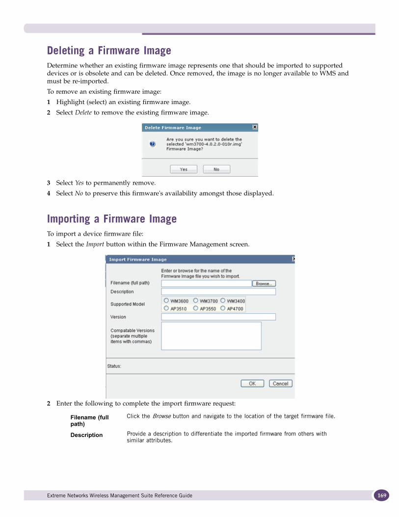
Deleting a Firmware ImageDetermine whether an existing firmware image represents one that should be imported to supported devices or is obsolete and can be deleted. Once removed, the image is no longer available to WMS and must be re-imported.
To remove an existing firmware image:
1 Highlight (select) an existing firmware image.
2 Select Delete to remove the existing firmware image.
3 Select Yes to permanently remove.
4 Select No to preserve this firmware's availability amongst those displayed.
Importing a Firmware ImageTo import a device firmware file:
1 Select the Import button within the Firmware Management screen.
2 Enter the following to complete the import firmware request:
Filename (full path)
Click the Browse button and navigate to the location of the target firmware file.
Description Provide a description to differentiate the imported firmware from others with similar attributes.
Extreme Networks Wireless Management Suite Reference Guide 169
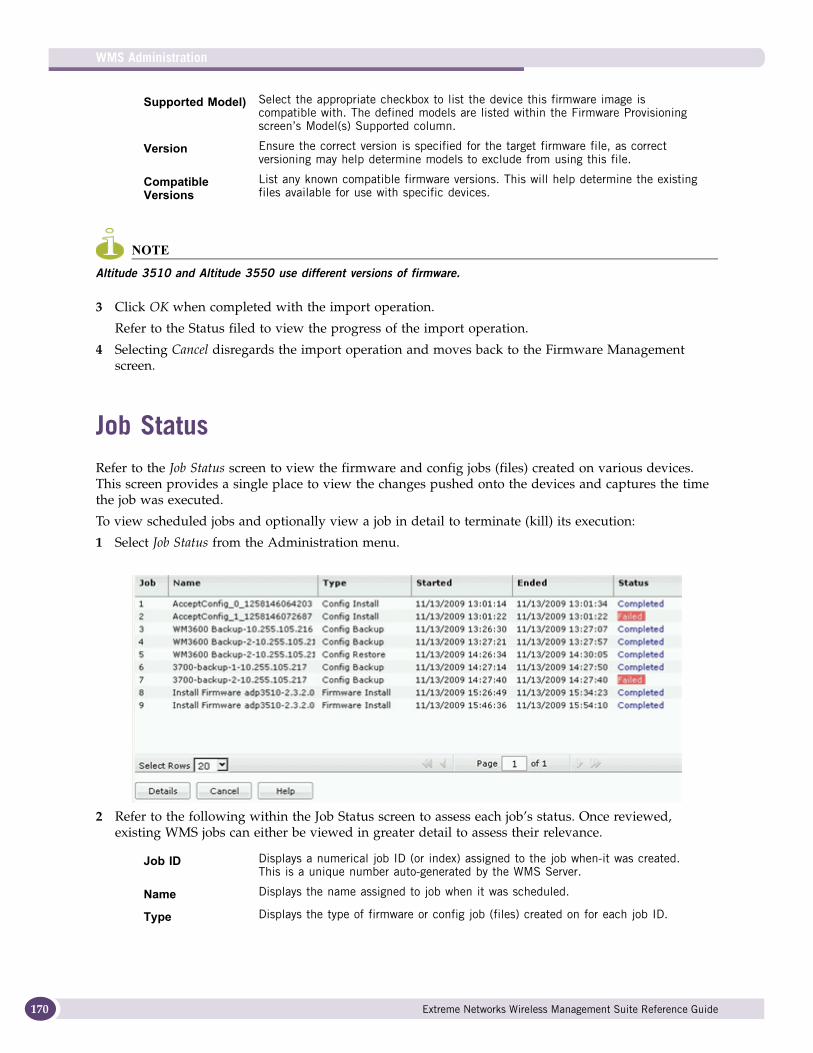
WMS Administration
170
NOTE
Altitude 3510 and Altitude 3550 use different versions of firmware.
3 Click OK when completed with the import operation.
Refer to the Status filed to view the progress of the import operation.
4 Selecting Cancel disregards the import operation and moves back to the Firmware Management screen.
Job StatusRefer to the Job Status screen to view the firmware and config jobs (files) created on various devices. This screen provides a single place to view the changes pushed onto the devices and captures the time the job was executed.
To view scheduled jobs and optionally view a job in detail to terminate (kill) its execution:
1 Select Job Status from the Administration menu.
2 Refer to the following within the Job Status screen to assess each job’s status. Once reviewed, existing WMS jobs can either be viewed in greater detail to assess their relevance.
Supported Model) Select the appropriate checkbox to list the device this firmware image is compatible with. The defined models are listed within the Firmware Provisioning screen’s Model(s) Supported column.
Version Ensure the correct version is specified for the target firmware file, as correct versioning may help determine models to exclude from using this file.
Compatible Versions
List any known compatible firmware versions. This will help determine the existing files available for use with specific devices.
Job ID Displays a numerical job ID (or index) assigned to the job when-it was created. This is a unique number auto-generated by the WMS Server.
Name Displays the name assigned to job when it was scheduled.
Type Displays the type of firmware or config job (files) created on for each job ID.
Extreme Networks Wireless Management Suite Reference Guide
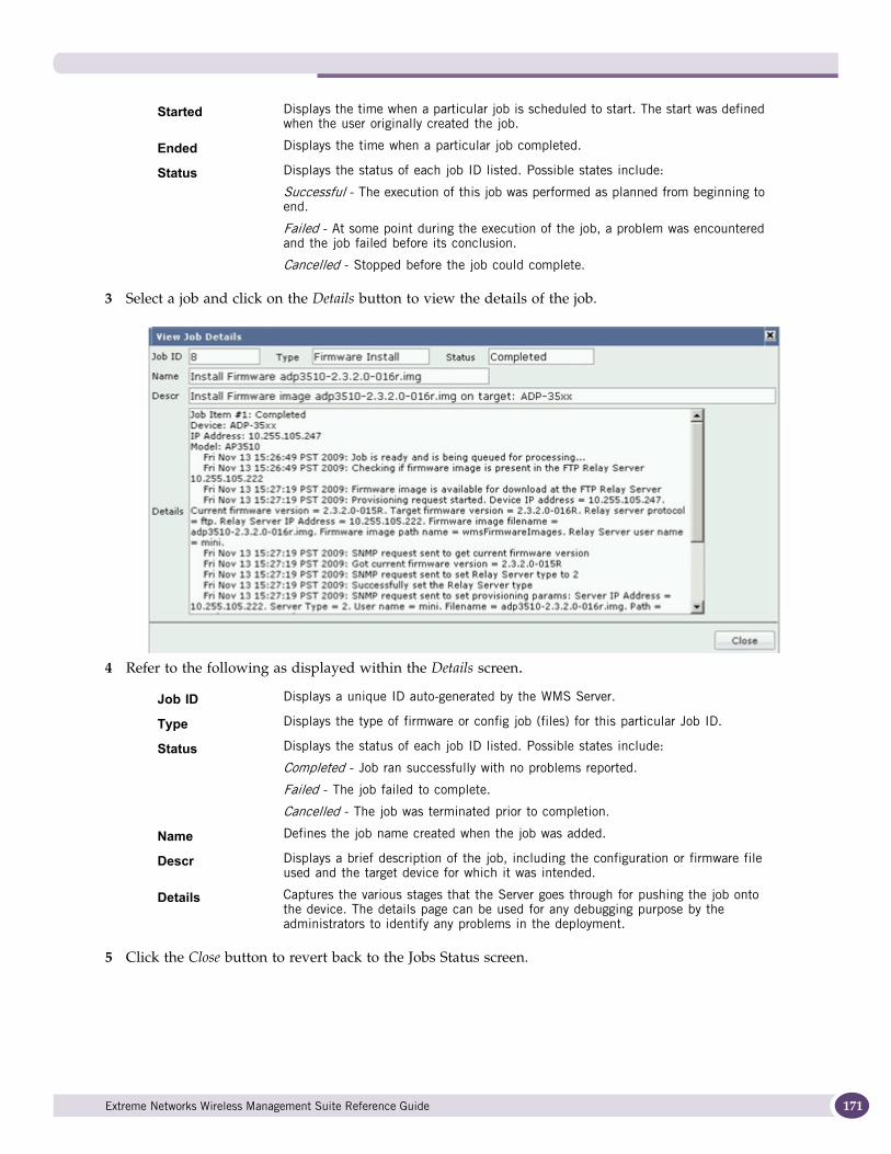
3 Select a job and click on the Details button to view the details of the job.
4 Refer to the following as displayed within the Details screen.
5 Click the Close button to revert back to the Jobs Status screen.
Started Displays the time when a particular job is scheduled to start. The start was defined when the user originally created the job.
Ended Displays the time when a particular job completed.
Status Displays the status of each job ID listed. Possible states include:
Successful - The execution of this job was performed as planned from beginning to end.
Failed - At some point during the execution of the job, a problem was encountered and the job failed before its conclusion.
Cancelled - Stopped before the job could complete.
Job ID Displays a unique ID auto-generated by the WMS Server.
Type Displays the type of firmware or config job (files) for this particular Job ID.
Status Displays the status of each job ID listed. Possible states include:
Completed - Job ran successfully with no problems reported.
Failed - The job failed to complete.
Cancelled - The job was terminated prior to completion.
Name Defines the job name created when the job was added.
Descr Displays a brief description of the job, including the configuration or firmware file used and the target device for which it was intended.
Details Captures the various stages that the Server goes through for pushing the job onto the device. The details page can be used for any debugging purpose by the administrators to identify any problems in the deployment.
Extreme Networks Wireless Management Suite Reference Guide 171
WMS Administration
172
Database ManagementRefer to the Database Management screen to manage the WMS database. WMS uses a database to archive and manage sites, users and configurations. Additionally, create a database backup image file that can restore the WMS server configuration. Creating a backup image is a recommended practice to periodically ensure WMS maintained device assets and data can be returned to their original state (at the time the backup is made). When backup jobs become obsolete, consider periodically purging (removing) them and replacing them with more current backups.
CAUTION
When the WMS database is restored from a backup, the current state of the database is completely erased before the backup image is applied.
CAUTION
Database information (reports and events) is deleted from the WMS database when it reaches its 5 GB capacity or after a configurable interval (the default is 14 days). Ensure you periodically backup the database to ensure information is properly archived.
The Database Management screen is partitioned into tabs supporting the following:
● Database Backup on page 172
● Database Restoration on page 174
● Database Details on page 175
● Database Purge on page 176
CAUTION
When restoring the WMS database, all users are logged off and the WMS process will be shut down and then brought back up.
Database Backup The Backup tab provides a means of creating an database backup image file that can be used (at a future date) to restore the WMS server to a backed-up state. Backup the WMS database as needed when critical information requires archive. Multiple devices can be backed up simultaneously.
CAUTION
Database information (reports and events) is deleted from the WMS database when it reaches its 5 GB capacity or after a configurable interval (the default is 14 days). Ensure you periodically backup the database to ensure information is properly archived.
To perform a WMS database backup operation:
1 Select Database Management from the Administration menu.
The Backup tab displays by default.
Extreme Networks Wireless Management Suite Reference Guide
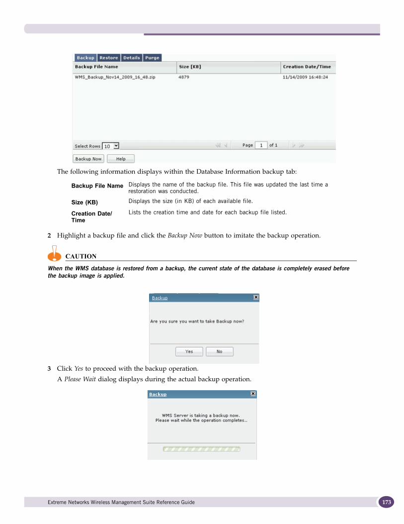
The following information displays within the Database Information backup tab:
2 Highlight a backup file and click the Backup Now button to imitate the backup operation.
CAUTION
When the WMS database is restored from a backup, the current state of the database is completely erased before the backup image is applied.
3 Click Yes to proceed with the backup operation.
A Please Wait dialog displays during the actual backup operation.
Backup File Name Displays the name of the backup file. This file was updated the last time a restoration was conducted.
Size (KB) Displays the size (in KB) of each available file.
Creation Date/Time
Lists the creation time and date for each backup file listed.
Extreme Networks Wireless Management Suite Reference Guide 173
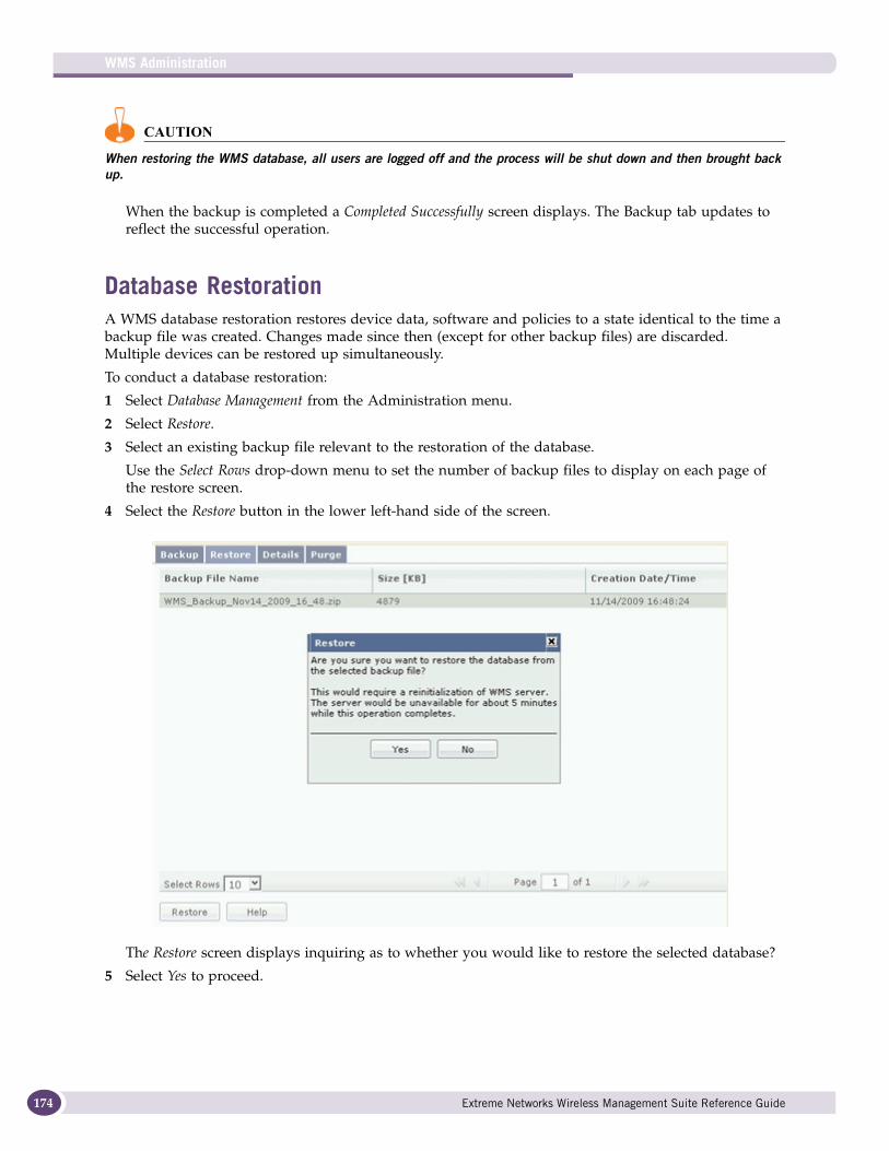
WMS Administration
174
CAUTION
When restoring the WMS database, all users are logged off and the process will be shut down and then brought back up.
When the backup is completed a Completed Successfully screen displays. The Backup tab updates to reflect the successful operation.
Database RestorationA WMS database restoration restores device data, software and policies to a state identical to the time a backup file was created. Changes made since then (except for other backup files) are discarded. Multiple devices can be restored up simultaneously.
To conduct a database restoration:
1 Select Database Management from the Administration menu.
2 Select Restore.
3 Select an existing backup file relevant to the restoration of the database.
Use the Select Rows drop-down menu to set the number of backup files to display on each page of the restore screen.
4 Select the Restore button in the lower left-hand side of the screen.
The Restore screen displays inquiring as to whether you would like to restore the selected database?
5 Select Yes to proceed.
Extreme Networks Wireless Management Suite Reference Guide
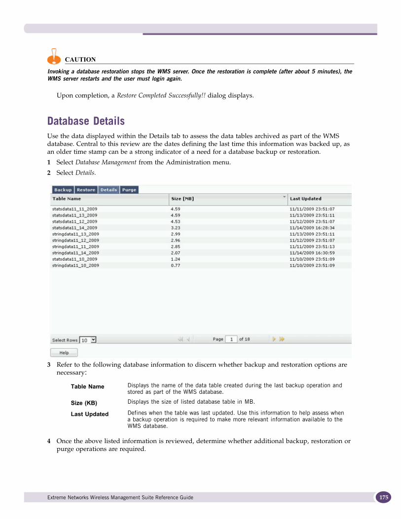
CAUTION
Invoking a database restoration stops the WMS server. Once the restoration is complete (after about 5 minutes), the WMS server restarts and the user must login again.
Upon completion, a Restore Completed Successfully!! dialog displays.
Database DetailsUse the data displayed within the Details tab to assess the data tables archived as part of the WMS database. Central to this review are the dates defining the last time this information was backed up, as an older time stamp can be a strong indicator of a need for a database backup or restoration.
1 Select Database Management from the Administration menu.
2 Select Details.
3 Refer to the following database information to discern whether backup and restoration options are necessary:
4 Once the above listed information is reviewed, determine whether additional backup, restoration or purge operations are required.
Table Name Displays the name of the data table created during the last backup operation and stored as part of the WMS database.
Size (KB) Displays the size of listed database table in MB.
Last Updated Defines when the table was last updated. Use this information to help assess when a backup operation is required to make more relevant information available to the WMS database.
Extreme Networks Wireless Management Suite Reference Guide 175
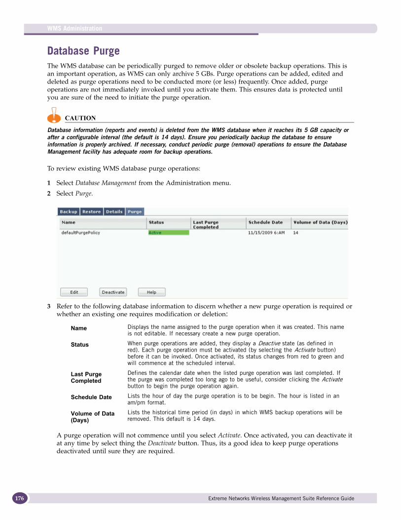
WMS Administration
176
Database PurgeThe WMS database can be periodically purged to remove older or obsolete backup operations. This is an important operation, as WMS can only archive 5 GBs. Purge operations can be added, edited and deleted as purge operations need to be conducted more (or less) frequently. Once added, purge operations are not immediately invoked until you activate them. This ensures data is protected until you are sure of the need to initiate the purge operation.
CAUTION
Database information (reports and events) is deleted from the WMS database when it reaches its 5 GB capacity or after a configurable interval (the default is 14 days). Ensure you periodically backup the database to ensure information is properly archived. If necessary, conduct periodic purge (removal) operations to ensure the Database Management facility has adequate room for backup operations.
To review existing WMS database purge operations:
1 Select Database Management from the Administration menu.
2 Select Purge.
3 Refer to the following database information to discern whether a new purge operation is required or whether an existing one requires modification or deletion:
A purge operation will not commence until you select Activate. Once activated, you can deactivate it at any time by select thing the Deactivate button. Thus, its a good idea to keep purge operations deactivated until sure they are required.
Name Displays the name assigned to the purge operation when it was created. This name is not editable. If necessary create a new purge operation.
Status When purge operations are added, they display a Deactive state (as defined in red). Each purge operation must be activated (by selecting the Activate button) before it can be invoked. Once activated, its status changes from red to green and will commence at the scheduled interval.
Last Purge Completed
Defines the calendar date when the listed purge operation was last completed. If the purge was completed too long ago to be useful, consider clicking the Activate button to begin the purge operation again.
Schedule Date Lists the hour of day the purge operation is to be begin. The hour is listed in an am/pm format.
Volume of Data (Days)
Lists the historical time period (in days) in which WMS backup operations will be removed. This default is 14 days.
Extreme Networks Wireless Management Suite Reference Guide
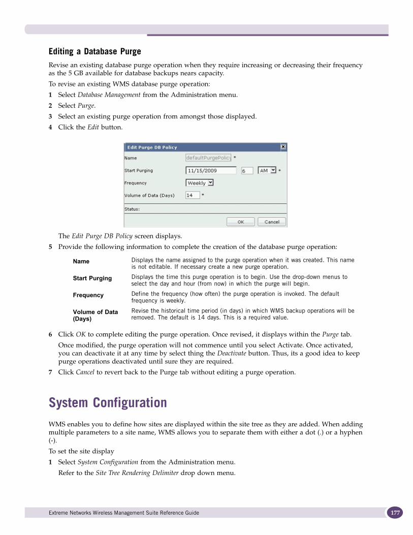
Editing a Database PurgeRevise an existing database purge operation when they require increasing or decreasing their frequency as the 5 GB available for database backups nears capacity.
To revise an existing WMS database purge operation:
1 Select Database Management from the Administration menu.
2 Select Purge.
3 Select an existing purge operation from amongst those displayed.
4 Click the Edit button.
The Edit Purge DB Policy screen displays.
5 Provide the following information to complete the creation of the database purge operation:
6 Click OK to complete editing the purge operation. Once revised, it displays within the Purge tab.
Once modified, the purge operation will not commence until you select Activate. Once activated, you can deactivate it at any time by select thing the Deactivate button. Thus, its a good idea to keep purge operations deactivated until sure they are required.
7 Click Cancel to revert back to the Purge tab without editing a purge operation.
System ConfigurationWMS enables you to define how sites are displayed within the site tree as they are added. When adding multiple parameters to a site name, WMS allows you to separate them with either a dot (.) or a hyphen (-).
To set the site display
1 Select System Configuration from the Administration menu.
Refer to the Site Tree Rendering Delimiter drop down menu.
Name Displays the name assigned to the purge operation when it was created. This name is not editable. If necessary create a new purge operation.
Start Purging Displays the time this purge operation is to begin. Use the drop-down menus to select the day and hour (from now) in which the purge will begin.
Frequency Define the frequency (how often) the purge operation is invoked. The default frequency is weekly.
Volume of Data (Days)
Revise the historical time period (in days) in which WMS backup operations will be removed. The default is 14 days. This is a required value.
Extreme Networks Wireless Management Suite Reference Guide 177
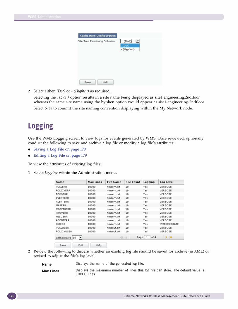
WMS Administration
178
2 Select either. (Dot) or - (Hyphen) as required.
Selecting the . (Dot ) option results in a site name being displayed as site1.engineering.2ndfloor whereas the same site name using the hyphen option would appear as site1-engineering-2ndfloor.
Select Save to commit the site naming convention displaying within the My Network node.
LoggingUse the WMS Logging screen to view logs for events generated by WMS. Once reviewed, optionally conduct the following to save and archive a log file or modify a log file’s attributes:
● Saving a Log File on page 179
● Editing a Log File on page 179
To view the attributes of existing log files:
1 Select Logging within the Administration menu.
2 Review the following to discern whether an existing log file should be saved for archive (in XML) or revised to adjust the file’s log level.
Name Displays the name of the generated log file.
Max Lines Displays the maximum number of lines this log file can store. The default value is 10000 lines.
Extreme Networks Wireless Management Suite Reference Guide
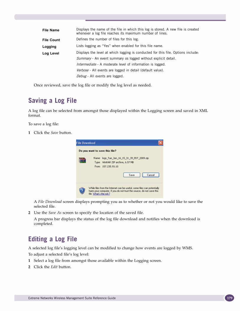
Once reviewed, save the log file or modify the log level as needed.
Saving a Log FileA log file can be selected from amongst those displayed within the Logging screen and saved in XML format.
To save a log file:
1 Click the Save button.
A File Download screen displays prompting you as to whether or not you would like to save the selected file.
2 Use the Save As screen to specify the location of the saved file.
A progress bar displays the status of the log file download and notifies when the download is completed.
Editing a Log FileA selected log file’s logging level can be modified to change how events are logged by WMS.
To adjust a selected file’s log level:
1 Select a log file from amongst those available within the Logging screen.
2 Click the Edit button.
File Name Displays the name of the file in which this log is stored. A new file is created whenever a log file reaches its maximum number of lines.
File Count Defines the number of files for this log.
Logging Lists logging as “Yes” when enabled for this file name.
Log Level Displays the level at which logging is conducted for this file. Options include:
Summary - An event summary os logged without explicit detail.
Intermediate - A moderate level of information is logged.
Verbose - All events are logged in detail (default value).
Debug - All events are logged.
Extreme Networks Wireless Management Suite Reference Guide 179

WMS Administration
180
3 Refer to the following, and if necessary, change the log level:
NOTE
Logging levels are common for all logged events. Changing the logging levels impacts all events.
4 Click OK to save the revised log level.
5 Select Cancel to disregard the log level modification and revert back to the Logging screen.
Import/ExportThe Import/Export screen enables WMS administrator to import/export information relating to User Management, Site Management, Security Management, Network Discovery and Notification Templates from one location.
Maximum Lines Displays the maximum number of lines this log file can store. The maximum value is 10,000 lines. This is a required value, but is set as 10000 by default.
Log Levels Displays the current level at which logging is conducted for this file. This is a default value, but is set at VERBOSE by default. Change the level to one of the following options:
Summary - An event summary is logged without explicit detail.
Intermediate - A moderate level of information is logged.
Verbose - All events are logged in detail (default value).
Debug - All events are logged.
Extreme Networks Wireless Management Suite Reference Guide
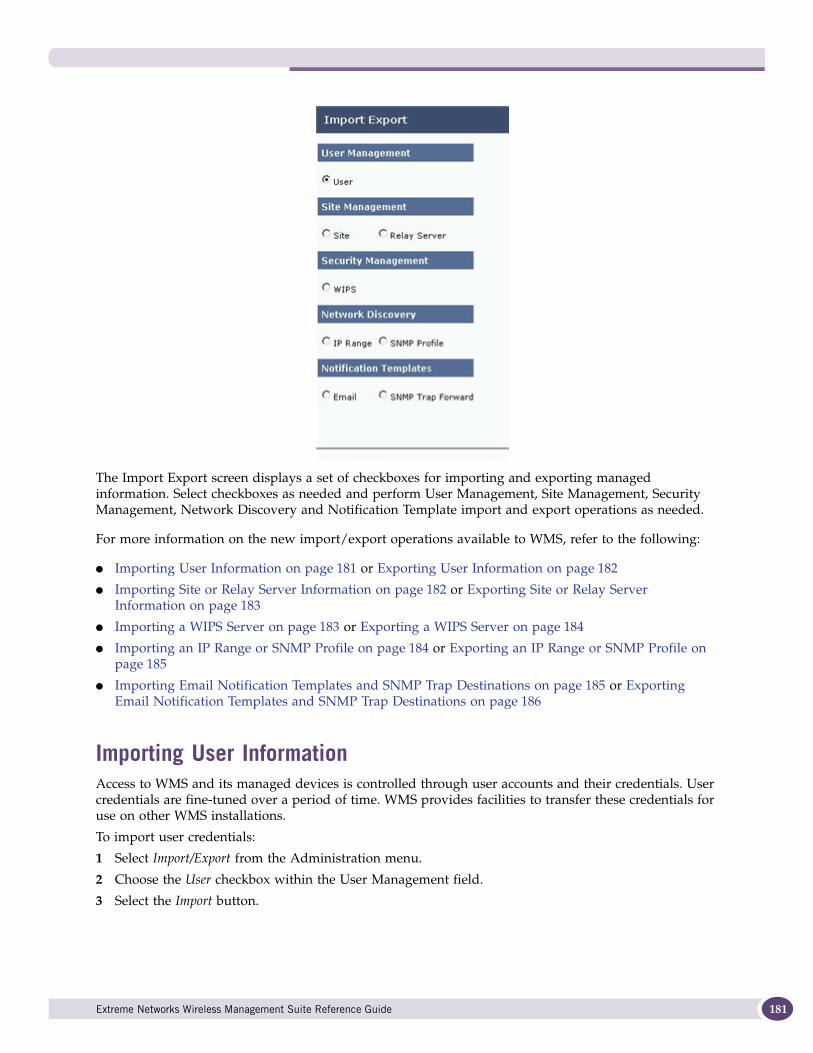
The Import Export screen displays a set of checkboxes for importing and exporting managed information. Select checkboxes as needed and perform User Management, Site Management, Security Management, Network Discovery and Notification Template import and export operations as needed.
For more information on the new import/export operations available to WMS, refer to the following:
● Importing User Information on page 181 or Exporting User Information on page 182
● Importing Site or Relay Server Information on page 182 or Exporting Site or Relay Server Information on page 183
● Importing a WIPS Server on page 183 or Exporting a WIPS Server on page 184
● Importing an IP Range or SNMP Profile on page 184 or Exporting an IP Range or SNMP Profile on page 185
● Importing Email Notification Templates and SNMP Trap Destinations on page 185 or Exporting Email Notification Templates and SNMP Trap Destinations on page 186
Importing User InformationAccess to WMS and its managed devices is controlled through user accounts and their credentials. User credentials are fine-tuned over a period of time. WMS provides facilities to transfer these credentials for use on other WMS installations.
To import user credentials:
1 Select Import/Export from the Administration menu.
2 Choose the User checkbox within the User Management field.
3 Select the Import button.
Extreme Networks Wireless Management Suite Reference Guide 181
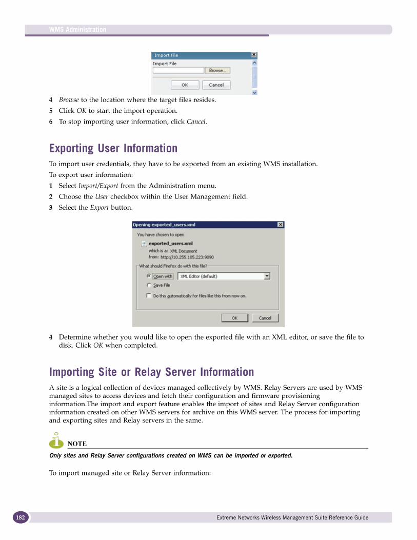
WMS Administration
182
4 Browse to the location where the target files resides.
5 Click OK to start the import operation.
6 To stop importing user information, click Cancel.
Exporting User InformationTo import user credentials, they have to be exported from an existing WMS installation.
To export user information:
1 Select Import/Export from the Administration menu.
2 Choose the User checkbox within the User Management field.
3 Select the Export button.
4 Determine whether you would like to open the exported file with an XML editor, or save the file to disk. Click OK when completed.
Importing Site or Relay Server InformationA site is a logical collection of devices managed collectively by WMS. Relay Servers are used by WMS managed sites to access devices and fetch their configuration and firmware provisioning information.The import and export feature enables the import of sites and Relay Server configuration information created on other WMS servers for archive on this WMS server. The process for importing and exporting sites and Relay servers in the same.
NOTE
Only sites and Relay Server configurations created on WMS can be imported or exported.
To import managed site or Relay Server information:
Extreme Networks Wireless Management Suite Reference Guide
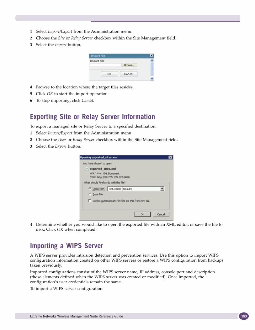
1 Select Import/Export from the Administration menu.
2 Choose the Site or Relay Server checkbox within the Site Management field.
3 Select the Import button.
4 Browse to the location where the target files resides.
5 Click OK to start the import operation.
6 To stop importing, click Cancel.
Exporting Site or Relay Server InformationTo export a managed site or Relay Server to a specified destination:
1 Select Import/Export from the Administration menu.
2 Choose the User or Relay Server checkbox within the Site Management field.
3 Select the Export button.
4 Determine whether you would like to open the exported file with an XML editor, or save the file to disk. Click OK when completed.
Importing a WIPS ServerA WIPS server provides intrusion detection and prevention services. Use this option to import WIPS configuration information created on other WIPS servers or restore a WIPS configuration from backups taken previously.
Imported configurations consist of the WIPS server name, IP address, console port and description (those elements defined when the WIPS server was created or modified). Once imported, the configuration’s user credentials remain the same.
To import a WIPS server configuration:
Extreme Networks Wireless Management Suite Reference Guide 183
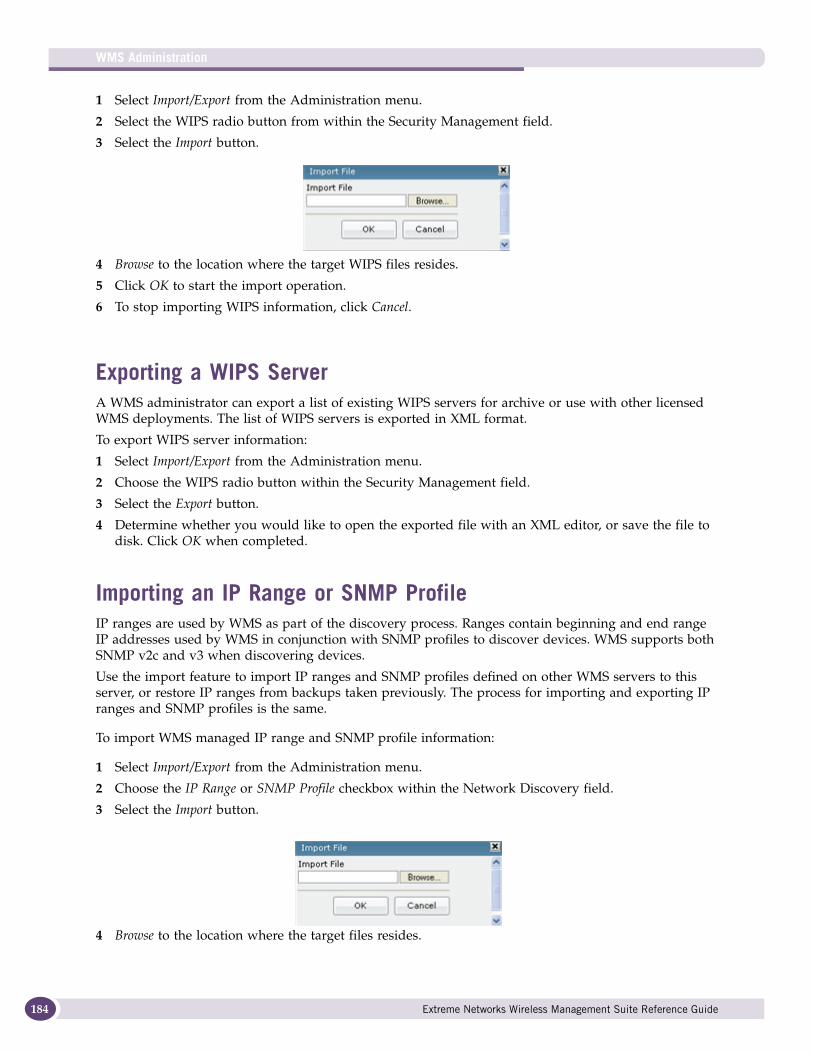
WMS Administration
184
1 Select Import/Export from the Administration menu.
2 Select the WIPS radio button from within the Security Management field.
3 Select the Import button.
4 Browse to the location where the target WIPS files resides.
5 Click OK to start the import operation.
6 To stop importing WIPS information, click Cancel.
Exporting a WIPS ServerA WMS administrator can export a list of existing WIPS servers for archive or use with other licensed WMS deployments. The list of WIPS servers is exported in XML format.
To export WIPS server information:
1 Select Import/Export from the Administration menu.
2 Choose the WIPS radio button within the Security Management field.
3 Select the Export button.
4 Determine whether you would like to open the exported file with an XML editor, or save the file to disk. Click OK when completed.
Importing an IP Range or SNMP ProfileIP ranges are used by WMS as part of the discovery process. Ranges contain beginning and end range IP addresses used by WMS in conjunction with SNMP profiles to discover devices. WMS supports both SNMP v2c and v3 when discovering devices.
Use the import feature to import IP ranges and SNMP profiles defined on other WMS servers to this server, or restore IP ranges from backups taken previously. The process for importing and exporting IP ranges and SNMP profiles is the same.
To import WMS managed IP range and SNMP profile information:
1 Select Import/Export from the Administration menu.
2 Choose the IP Range or SNMP Profile checkbox within the Network Discovery field.
3 Select the Import button.
4 Browse to the location where the target files resides.
Extreme Networks Wireless Management Suite Reference Guide
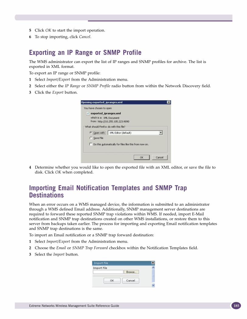
5 Click OK to start the import operation.
6 To stop importing, click Cancel.
Exporting an IP Range or SNMP ProfileThe WMS administrator can export the list of IP ranges and SNMP profiles for archive. The list is exported in XML format.
To export an IP range or SNMP profile:
1 Select Import/Export from the Administration menu.
2 Select either the IP Range or SNMP Profile radio button from within the Network Discovery field.
3 Click the Export button.
4 Determine whether you would like to open the exported file with an XML editor, or save the file to disk. Click OK when completed.
Importing Email Notification Templates and SNMP Trap DestinationsWhen an error occurs on a WMS managed device, the information is submitted to an administrator through a WMS defined Email address. Additionally, SNMP management server destinations are required to forward these reported SNMP trap violations within WMS. If needed, import E-Mail notification and SNMP trap destinations created on other WMS installations, or restore them to this server from backups taken earlier. The process for importing and exporting Email notification templates and SNMP trap destinations is the same.
To import an Email notification or a SNMP trap forward destination:
1 Select Import/Export from the Administration menu.
2 Choose the Email or SNMP Trap Forward checkbox within the Notification Templates field.
3 Select the Import button.
Extreme Networks Wireless Management Suite Reference Guide 185
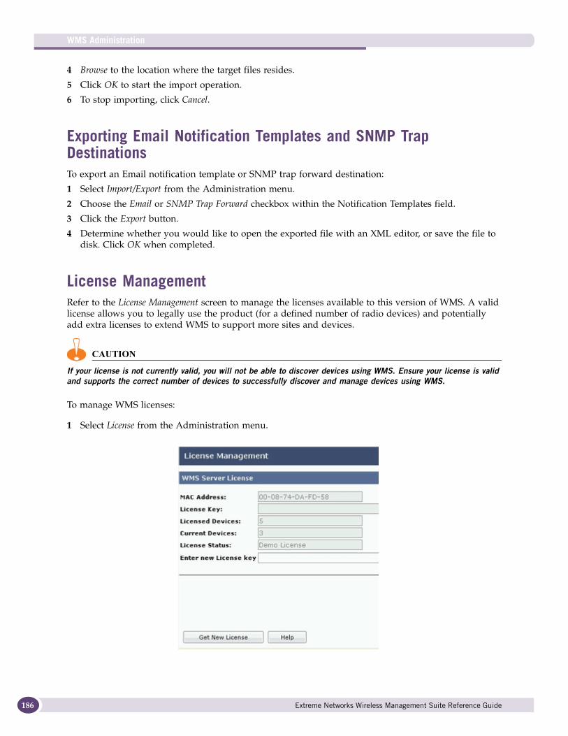
WMS Administration
186
4 Browse to the location where the target files resides.
5 Click OK to start the import operation.
6 To stop importing, click Cancel.
Exporting Email Notification Templates and SNMP Trap DestinationsTo export an Email notification template or SNMP trap forward destination:
1 Select Import/Export from the Administration menu.
2 Choose the Email or SNMP Trap Forward checkbox within the Notification Templates field.
3 Click the Export button.
4 Determine whether you would like to open the exported file with an XML editor, or save the file to disk. Click OK when completed.
License Management Refer to the License Management screen to manage the licenses available to this version of WMS. A valid license allows you to legally use the product (for a defined number of radio devices) and potentially add extra licenses to extend WMS to support more sites and devices.
CAUTION
If your license is not currently valid, you will not be able to discover devices using WMS. Ensure your license is valid and supports the correct number of devices to successfully discover and manage devices using WMS.
To manage WMS licenses:
1 Select License from the Administration menu.
Extreme Networks Wireless Management Suite Reference Guide

The License Management screen displays the status of the current license.
2 Refer to the WMS Server License field to review the attributes of the licence:
3 To obtain a new license for legally using WMS, click the Get New License button.
MAC Address Displays the MAC address of the Windows 2003 Server where this version of WMS is installed. This is the MAC address bound to the license for legal use of WMS.
License Key Displays the license key string generated by Extreme Networks for the legal use of this version of WMS.
Licensed Devices Lists the number of devices licensed for legal use by this installed version of WMS. Compare this number against the Current Devices to determine how close you are to exceeding you license.
Current Devices Lists the number of devices currently managed by this version of WMS. If this number exceeds your license, you are using WMS illegally and need to scale you license accordingly.
License Status Displays the status of this WMS license. If the number of managed devices exceeds the number of device licenses, the status is Not Valid.
Enter new License Key
If you have acquired a new license key (to upgrade you legal device usage or other), enter the new license string here.
Extreme Networks Wireless Management Suite Reference Guide 187
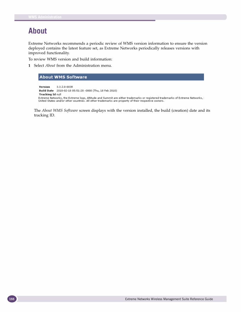
WMS Administration
188
About Extreme Networks recommends a periodic review of WMS version information to ensure the version deployed contains the latest feature set, as Extreme Networks periodically releases versions with improved functionality.
To review WMS version and build information:
1 Select About from the Administration menu.
The About WMS Software screen displays with the version installed, the build (creation) date and its tracking ID.
Extreme Networks Wireless Management Suite Reference Guide

A Customer Support
NOTE
Services can be purchased from Extreme Networks or through one of its channel partners. If you are an end-user who has purchased service through an Extreme Networks channel partner, please contact your partner first for support.
Extreme Networks Technical Assistance Centers (TAC) provide 24x7x365 worldwide coverage. These centers are the focal point of contact for post-sales technical and network-related questions or issues. TAC will create a Service Request (SR) number and manage all aspects of the SR until it is resolved. For a complete guide to customer support, see the Technical Assistance Center User Guide at:
www.extremenetworks.com/go/TACUserGuide
The Extreme Networks eSupport website provides the latest information on Extreme Networks products, including the latest Release Notes, troubleshooting, downloadable updates or patches as appropriate, and other useful information and resources. Directions for contacting the Extreme Networks Technical Assistance Centers are also available from the eSupport website at:
https://esupport.extremenetworks.com
RegistrationIf you have not already registered with Extreme Networks using a registration card supplied with your product, you can register on the Extreme Networks website at:
http://www.extremenetworks.com/go/productregistration.
DocumentationCheck for the latest versions of documentation on the Extreme Networks documentation website at:
http://www.extremenetworks.com/go/documentation
Extreme Networks Wireless Management Suite Reference Guide 189

Customer Support
190
Extreme Networks Wireless Management Suite Reference Guide