Extracted Pages From Estimacion Trabajos Electricos
70
CHAPTER 2 Electrical Material and Labor Takeoff Typical Electrical Symbol List The symbols shown below are generic in nature, but they give the estimator a guide while doing a takeoff. Review this list and become familiar with the symbols. Some estimators will photocopy the symbols and keep them handy rather than keep fumbling through plans. Each engineer has symbol lists they use that may vary with others, but basic symbols are the same throughout the industry and will be on all symbol lists. s s2 s3 s4 s, Wp dim 0 @ @ Single-pole switch, amp, and volt rating in specs Two-pole switch, amp, and volt rating in specs Three-way switch, amp, and volt rating in specs Four-way switch, amp, and volt rating in specs Single-pole switch with lighted handle, amp, and volt rating in specs Weather proof (nema rating as shown on plans and in specs) Dimmer switch rating, voltage, type, and incandescent or fluorescent in specs Duplex receptacle, amp, and volt rating in specs Single (simplex) receptacle, amp, and volt rating in specs Special receptacle, amp, and volt rating in specs F Duplex receptacle in a floor box, amp, volt, and type in specs eXpl0 Explosion proof (class and division ratings in specs) tifmn: Duplex receptacle-2 gang floor box with combo cover for receptacle and communication jack, in specs Enclosed circuit breaker as shown on plans and in specs Disconnect switch; I-, 2- or 3-pole amp and volt as shown on plans and in specs Combination disconnect and starter as shown on plans and in specs Starter as shown on plans and in specs Single-pole manual motor starter as shown on plans and in specs Control station with buttons, switches, and/or lights as shown on plans and in specs Sm Sm, Single-pole manual motor starter with pilot light as shown on plans and in specs 1 9
description
ESTIMACION TRABAJOS ELECTRICOS
Transcript of Extracted Pages From Estimacion Trabajos Electricos

CHAPTER 2
Electrical Material and Labor Takeoff
Typical Electrical Symbol List The symbols shown below are generic in nature, but they give the estimator a guide while doing a takeoff. Review this list and become familiar with the symbols. Some estimators will photocopy the symbols and keep
them handy rather than keep fumbling through plans. Each engineer has symbol lists they use that may vary with others, but basic symbols are the same throughout the industry and will be on all symbol lists.
s s2 s3 s4
s, W p dim
0 @ @
Single-pole switch, amp, and volt rating in specs Two-pole switch, amp, and volt rating in specs Three-way switch, amp, and volt rating in specs Four-way switch, amp, and volt rating in specs Single-pole switch with lighted handle, amp, and volt rating in specs Weather proof (nema rating as shown on plans and in specs) Dimmer switch rating, voltage, type, and incandescent or fluorescent in specs
Duplex receptacle, amp, and volt rating in specs Single (simplex) receptacle, amp, and volt rating in specs Special receptacle, amp, and volt rating in specs
F Duplex receptacle in a floor box, amp, volt, and type in specs
eXpl0 Explosion proof (class and division ratings in specs)
tifmn: Duplex receptacle-2 gang floor box with combo cover for receptacle and communication jack, in specs Enclosed circuit breaker as shown on plans and in specs Disconnect switch; I-, 2- or 3-pole amp and volt as shown on plans and in specs Combination disconnect and starter as shown on plans and in specs Starter as shown on plans and in specs Single-pole manual motor starter as shown on plans and in specs
Control station with buttons, switches, and/or lights as shown on plans and in specs
Sm Sm, Single-pole manual motor starter with pilot light as shown on plans and in specs
1 9

10 How to Estimate Electrical Construction Projects
Contactor as shown on plans and in specs l ime clock as shown on plans and in specs Photocell as shown on plans and in specs Relay as shown on plans and in specs
Single-phase electric motor as shown on plans and in specs Three-phase electric motor as shown on plans and in specs Unit heater as shown on plans and in specs Cabinet heater as shown on plans and in specs Heating, ventilating, and air-conditioning unit as shown on plans and in specs Ground connection as shown on plans and in specs Transformer as shown on plans and in specs
1-1 Switchboard as shown on plans and in specs Main distribution panel as shown on plans and in specs Power panel as shown on plans and in specs Lighting panel as shown on plans and in specs Receptacle panel as shown on plans and in specs Manhole as shown on plans and in specs Handhole as shown on plans and in specs Raceway exposed as shown on plans and in specs Raceway concealed in slab or below grade as shown on plans and in specs Raceway or cable concealed above finished floor as shown on plans and in specs
E1 Motor control center as shown on plans and in specs 0
4
6
F l
w\ - - - - 7
- SR - Surface raceway as shown on plans and in specs (metal or nonmetal) - MI - Mineral insulated cable as shown on plans and in specs -TC- Tray cable as shown on plans and in specs
Cable tray as shown on plans and in specs [include bends, hangers, drops, grounds, couplings, etc.) Feeder bus duct as shown on plans and in specs (include all associated components) Plug-in bus duct as shown on plans and in specs (include all associated components) Bus plug-in disconnect/circuit breaker as shown on plans and in specs Patch panel floor stand as shown on plans and in specs 64-port patch panel as shown on plans and in specs Shelf for patch panel and wire manager as shown on plans and in specs Floor box with data outlet as shown on plans and in specs Wall box with data outlet as shown on plans and in spec3 Floor box with voice outlet as shown on plans and in specs Wall box with voice outlet as shown on plans and in specs
100 pair #llO-voice block for voice communications as shown on plans and in specs - Communication backboard, size as shown on plans and in specs V P T Wall box for public telephone connection as shown on plans and in specs
0 e Incandescent light fixture recessed "TYPE" as shown on plans and in specs 0 4 Incandescent light fixture wall-mounted "TYPE" as shown on plans and in specs @ Exit light fixture ceiling-mounted "TYPE" as shown on plans and in specs
Exit light fixture wall-mounted "TYPE" as shown on plans and in specs 0 Incandescent light fixture recessed "TYPE" as shown on plans and in specs - Fluorescent light fixture 12" to 24" long surface-mounted "TYPE" as shown on plans and in specs
[171
mF VD B F mV
-
mF Two-gang floor box with data and voice outlet as shown on plans and in specs

Electrical Material and Labor Takeoff 11 - Fluorescent fixture 48" long surface I recessed I lay-in I suspended "TYPE" as shown on plans and in specs Fluorescent fixture 24" x 24" surface I recessed I lay-in I suspended "TYPE" as shown on plans and in specs 0 Fluorescent fixture 24" x 48" surface I recessed I lay-in I suspended "TYPE" as shown on plans and in specs
Fluorescent fixture 48" x 48" surface I recessed I lay-in I suspended "TYPE" as shown on plans and in specs - Fluorescent fixture 8' long surface I recessed I suspended "TYPE" as shown on plans and in specs n
Light-track surface-mounted "TYPE" and length as shown on plans and in specs Light-track fixture "TYPE" as shown on plans and in specs Chandelier suspended "TYPE" as shown on plans and in specs Emergency battery unit "TYPE" as shown on plans and in specs Emergency remote light "TYPE" as shown on plans and in specs HID lighting fixture "TYPE" as shown on plans and in specs HID lighting fixture "TYPE" as shown on plans and in specs Bollard for walkway "TYPE" as shown on plans and in specs Site lighting pole and one fixture "TYPE" as shown on plans and in specs Site lighting pole and two fixtures "TYPE" as shown on plans and in specs
Site lighting pole and four fixtures "TYPE" as shown on plans and in specs
In ground flagpole light as shown on plans and in specs Fire alarm panel with battery backup Fire alarm remote annunciator FAmanual pull station
Lr# FA combination horn and light
0 SD FA smoke detector 0 HD FAheat detector ODD FAduct detector with sampling tube ~ I L FAremote indicating light wl FA data gathering panel laahl FAremote module
FAflow switch FA tamper switch FA electro/magnetic door holder
-P FA outdoor combination horn and light
Ceiling Finishes As suggested previously, a good procedure for the esti- mator to follow is to review the architectural plan for the ceiling finishes. Let us look at the ceiling finishes partial floor plan (Fig. 2-1, p. 13).
You will see that all ceiling finishes are type "A" unless noted otherwise. A type "A" ceiling finish is to be a 2' x 4'
suspended grid with 2' x 4' acoustical ceiling tiles. A type "B" ceiling finish is to be a 2' x 2' suspended grid with 2'
x 2' acoustical ceiling tiles. A type "C" ceiling finish is to be a suspended framework for a sheetrock finish. Finally, a type "D" ceiling finish is to be exposed construction.
Reviewing the ceiling finishes prior to counting the light fixtures will save many headaches when purchas- ing the light fixtures and fixture frames for recessed light fixtures, pendants for suspended light fixtures, hold-down clips for lay-in light fixtures, shade aligners for light fixtures with RLM-type shades (reflectors), and airplane-type steel cable for suspended light fixtures.
The estimator should transfer the ceiling finishes in- formation to the electrical plans. Here is where colored highlighters will help the estimator-you can color code the various ceiling types on the electrical plans. Perhaps the ceiling finish with the greatest percentage of the

12 How to Estimate Electrical Construction Projects
ceiling construction would not be color coded; just color code the smaller ceiling areas. This will make the light fixture takeoff easier and more accurate than hurrying the takeoff and omitting some of the associated light fix- ture accessories. This color-coding method will avoid serious and costly mistakes.
Text Introduction to Fixtures Takeoff Before beginning to count the light fixtures, the estimator should have pencils, blank rough takeoff sheets, a few different colored highlighters, and a manual or electronic counter. These are essential for the estimator to keep handy at all times. As you begin to count the items, make a small colored slash mark on each item and record each item with the counter. It is a good idea to select a color for each division of the takeoff, such as fixtures, devices, and their wiring in orange, fire alarm systems in red, communications voice in green, data in yellow, etc. This method will ensure that each item will be counted only once (Figs. 2-2A, B, pp. 15 , 16). Note that there are many products on the market that can color and count at the same time. Use whatever you find most comfortable.
All of the fixtures are listed on the top section of the fixtures rough takeoff sheets (Figs. 2-3A, B, pp. 18,19). By listing the fixture type, size, mounting, lamps, voltage, etc., the estimator has a snapshot of the most important facts about the fixtures. Beginning with type “A” fixtures, count all of them on the floor plan and enter the total in the block under the description. Note that in the left-most column the estimator will list which plan the fixtures were counted from. There is a reason we takeoff the elec- trical items and list them according to which plan they were counted from. For example, if after the contracts are awarded, the owner requests that all of the type “B” light fixtures on the first floor be changed to another style or deleted, the estimator can turn to the rough takeoff sheets and very quickly respond to the request. This saves over- head time and money. The estimator does not have to open the plans and do another count on that type of fix- ture. This method applies to all of the takeoffs.
Text Recap of Fixtures Takeoff This concludes the light fixture counting and com- pletes the takeoff of all the building light fixtures. After
all the light fixtures have been counted, we total them and list all of the associated items needed to have a complete working lighting system for the building. Each fixture will have lamps, outlet boxes, junction boxes, flexible whips, etc. Other necessary items may be hold-down clips, suspension materials (pendants, chains, cables, etc.), splicing materials, fixture wire, and labor for testing and tagging. A flexible whip is allowed for each lay-in and recessed fixture. Wall- mounted fixtures will require a wall outlet box, as will some ceiling-mounted fixtures. The estimator should investigate which fixtures may be furnished with an outlet box and check all notes and the specifications for possible spare lamps and fixtures. There are occasions when the engineer will specify that a percentage of all types of lamps be turned over to the owner as spares at the completion of the project. The estimator must allow a sum of money for this requirement in the estimate.
The estimate sheets (Figs. 2-4A, B , pp. 20, 21) will show how all of the fixtures and associated materials are to be listed for pricing and the hours required for each material. The prices are not included due to each contrac- tor’s price structure with the material suppliers and actual price fluctuation in the markets. A few of the items such as hold-down clips, supports, splicing, tags, testing, etc. are allowance items of money and hours. These amounts will vary according to the size of each project.
Text Introduction to Devices Takeoff In order to count all the devices, we need to turn again to the lighting fixtures partial floor plan (see Fig. 2-2B,
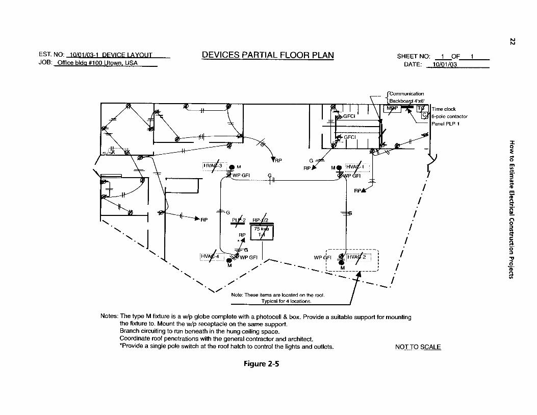
p. 16) to count the switches. This plan will show you that some of the switches are ganged together as re- quired (meaning more than one is utilized). When you count these switch locations, count them as you see them; for example, SSS is a three-gang box and plate with three switches. Counting the switches this way will not only give you the switch count, but will give you the count of the boxes (single or ganged) and the matching plate(s). These switch totals are listed on the devices rough takeoff sheet (Fig. 2-6, p. 24). Also on this sheet is a count of the receptacles shown on the partial device floor plan (Fig. 2-5, p. 22). You should check the specifications to see if any special covers or

Electrical Material and Labor Takeoff
13

14 How to Estimate Electrical Construction Projects
NOTES

Electrical Material and Labor Takeoff 15
SYMBOL - TYPE
A
A- 1
B
C
D
E
F
G
H
J
J-1
K
L
M
N
EM
EM
RH
FIXTURE LEGEND
DESCRl PTl ON
FLUORESCENT 277V LAY-IN 2' X 4' 3/32W CWRS LAMPS II II
I' 2 ' X 4' 2/32W CWRS LAMPS
I' 2' X 2' 2/32W U CWRS LAMPS
I' 4 'X 4' 6/32W CWRS LAMPS
II II
II II
II II RECESSED 1' X 4' 2/32W CWRS LAMPS & FRAME
EXIT LIGHT UNIVERSAL MOUNT 277V W/ LAMPS AND BATTERY
FLUORESCENT 277V RECESSED HIGH HAT W/ 1 PL LAMP II I' WALL MOUNTED W/1 PL LAMP
HI-PRESSURE SODIUM 277V W/P WALL MOUNTED W/ 1 70W LAMP
TRACK LIGHT FIXTURE 120V W/ 1 75W PAR LAMP
4' LONG TEE BAR MOUNTED LIGHTTRACK 120V 1 CIRCUIT & HARDWARE
FLUORESCENT 120V UNDER COUNTER PLUG IN FIXTURE 24" LONG I I 277V SUSPENDED FIXTURE W/ 2 32W CWRS LAMPS
INCANDESCENT FIXTURE W/P W/ 1 1OOW IF 130V LAMP & BOX I1 II I' W/ 1 150W PAR 38 FLOOD LAMP & PE
EMER' B A T UNIT 277V 2 HEADS WALL MTD. II II I1 II II
I' 1 HEAD
REMOTE EMER. BATT' HEAD
Figure 2-2A
colors for the devices are required. Normally the cata- log numbers of the devices are listed in the electrical specifications or on the symbol list. The architect may note special colors for all wall devices on the architec- tural plans: they might not be found elsewhere. This is why we stress the need for reviewing all the bidding documents for possible items that will affect the electri- cal estimate. Be assured that this will come up in your estimating at some point, so do not overlook the review of all the bidding documents.
The estimate sheet (Fig. 2-7 , p. 25) will show how all of the devices and associated materials are to be listed onto the estimate sheet for pricing and the hours required for each item.
The prices are not included due to each contractor's price structure with the material suppliers and actual price fluctuation in the markets. A few of the items such as the metal wall stud box supports are an allow- ance of money and hours. These amounts will vary ac- cording to the size and type of project.

16 H
ow to Estim
ate Electrical Construction Projects

Electrical Material and Labor Takeoff
NOTES
17

EST. NO: 10/01/03-1
Lighting Fixtures 2x4' lay-ir
LOCATION 277 volt ITEMS & 3 - 3 2 ~ cw
~
2
0
0
0
0
2
-
IXTURES ROUGH TAKEOFF SHEET
1
SHEETNO: 1 OF: 2
1
0
- Type "A-1 ' 2x4' lay-ir
277 volt 2 - 3 2 ~ cw
5
0
Type '8' 2'x2 lay-in
277 volt 2-32wU cw
1
0
1
0
0
0
0
1
-
8
0
0
0
0
1
0
0
0
5w/f rm's
T 4
Type 'EM" wall batt uni
2 heads 277 volt
emer unit
3
0
0
0
0
3
-
DATE:
0 1 ° 0 I 0
10/1/0: Type 'G' fluor' wall 1 pl lamp 277 volt (sconce)
3
0
0
0
0
3
-
Type 'H' wlp wall
277 volt 1 - 7 0 ~ hpS
4
0
0
0
0
4
-
Figure 2-3A

EST. NO: 10/01/03-1
Plan E-1 Lighting
Plan E-3 TeVData Panels &
"J" fittings "J" fittings internal 90 live end
hips
"J" fittings 'J" fittings "J" heads Type "K" Type 'L" Type "M" Type 'N" couplings 'T" bar clips cylinders 2 surf 4' susp'd w/p globe w/p spot &
TOTALS r
feed in with outlet cover for "T" bar
TOTALS
each with under cab' rlm reflect'r w/ box motion sent Remote en par20 75w 1-1 8w cw 2-32w cw 1-1 00 w if 1-1 50w par head
lamps 120 volt 277 volt 130 volt 120 volt
F w
Type "J" 8' track surf
1 circuit 120 volt
0
0
0
0
1 0 3 2 0 4 0 1 2
0 0 0 0 1 0 4 0 0
0
0
> 0
. - - - -
0
0
32 WAIT COOL WHT FLUO LAMF
0 0 0 0 0 0 0 0 0
0 0 0 0 0 0 0 0 0
74
0
- Type "J-I" 4' track surf
1 circuit 120 volt
1 0 3 2 1 4 4 1 2
18WAl-r DUAL PL LAMPS
1
0
IOOWATT 75WAlT 18WAIT 150WATT 70WAlT FIXTURE FIXTURE .FIXTURE FLEXIBLE INCAND PAR 20 COOL WHT PAR 38 FL HPS BD OUTLET OUTLET JUNCTION FIXTURE LAMPS LAMPS FLUORLAMP LAMPS CLEAR BOXES BOXES BOXES WHIPS 120 v 120 v 120 v LAMP WALL IN CEIL'NG 4"SQ&COV
0
0
2 1
- - - - -
11
32 WAIT U COOL WHT FLUO LAMF
4 2 1 1 4 17 20 a 33 4
0 0 0 0 0 0 0 0 0 0
I Allow materials for independently supporting all light fixtures mounted in or on suspended ceilings.
Allow for hold-down clips on lay-in fixtures, splicing materials tags, testing, etc.
Figure 2-3B

20 How to Estimate Electrical Construction Projects
ESTIMATE SHEET ESTIMATE NO: 10/01/03-1
JOB: Office bldq' #lo0 Utown, USA PAGENO: 1 OF 2 Estimate Sheet of Fixtures Labor Hours
CHCKDBY: Sr. DATE: 10101103 ESTIMATED BY: F S. T.
1
2
3
4
5
6
7
8
9
10
11
12
13
14
15
16
17
18
19
20
21
22
23
24
25
26
27
28
29
30
31
32
Figure 2-4A

Electrical Material and Labor Takeoff 21
ESTIMATE SHEET ESTIMATE NO: 10/01/03-1
JOB: Office bldq' #lo0 Utown, USA PAGENO: 2 OF 2 Estimate Sheet of Fixtures Labor Hours
ESTIMATED BY: M C CHCKDBY: Sr. DATE: 10/01/03
I DESCRIPTION OF MATERIALS MATERIALS i LABOR t QUANTITY I UNITCOST I PERI AMOUNT I UNIT I PEF
I I I I i i
1 -FIXTURE OUTLET BOXES FOR WALL 17 EA 0.35 EA
0.35 EA 2 FIXTURE OUTLET IN CEILING SPACE 20 EA
0.35 EA 3 4" SQ' BOXES W1 BLANK COVERS 8 EA
0.1 EA 4 FLEXIBLE FIXTURE WHIPS W/WIRE 33 EA
5
6 HOLD-DOWN CLIPS FOR LAY-IN FIXTURES
7 INDEPENDENT SUPPORTS FOR LAY-IN FIXT'S
ALLOW
ALLOW
8
9
10
11
12
13
14
15
16
17
18
19
20
21
22
23
24
25
26
aving out a price or hours are greatly reduced. Get in the habit of making a line from the quantity column to the labor hours amount column. Leave open only those spaces that require material prices and labor hours! This applies to all estimate sheets of the estimate from
e recapitulation sheet to the last estimate sheet.
"7 I ~
28 I 29 I 30 I 31 I
I 32
EA = Each TOTAL TOTAL
7
8
og 12
13
14
15
16
17
18
19
20
21
22
23
24
25
26
27
28
29
30
31
32
1 21.55
Figure 2-4B
N N
DEVICES PARTIAL FLOOR PLAN SHEETNO: 1 OF 1 DATE: 10/01/03
6-pole contactor
' '. '0
tl I I i i
I I i i
Note: These items are located on the roof. Typical for 4 locations.
Notes: The type M fixture is a w/p globe complete with a photocell & box. Provide a suitable support for mounting the fixture to. Mount the w/p receptacle on the same support. Branch circuiting to run beneath in the hung ceiling space. Coordinate roof penetrations with the general contractor and architect. *Provide a single pole switch at the roof hatch to control the lights and outlets. NOT TO SCALE
Figure 2-5

Electrical Material and Labor Takeoff
NOTES
23

24 H
ow to Estim
ate Electrical Construction Projects
..
.
.
::

Electrical Material and Labor Takeoff
31
32
25
I I I I I I 31 I I 32
EA = Each INC = Included TOTAL TOTAL 30.85
ESTIMATE SHEET ESTIMATE NO: 10/01/03-1
JOB: Office bldg' #lo0 Utown, USA PAGENO: 1 OF 1 Estimate Sheet of Devices Labor Hours
ESTIMATED BY: Mr. EST. CHCKDBY: Sr. DATE: 10/01/03
DESCRIPTION OF MATERIALS MATERIALS I LABORHOURS QUANTITY I UNITCOST I PERI AMOUNT I UNIT I PERI AMOUNT
1 1
2 2
3 3
4 4
5 5
6 6
7 7
8 8
9 9
10 10
11 11
12 12
13 13
14 14
15 15
16 16
17 17
18 18
19 19
20 20
21 21
22 22
23 / 23
24 I 24 I I
26 I 26
27 I I 27 -, I I
29 I 29
30 I I 30 I I
Figure 2-7
26 How to Estimate Electrical Construction Projects
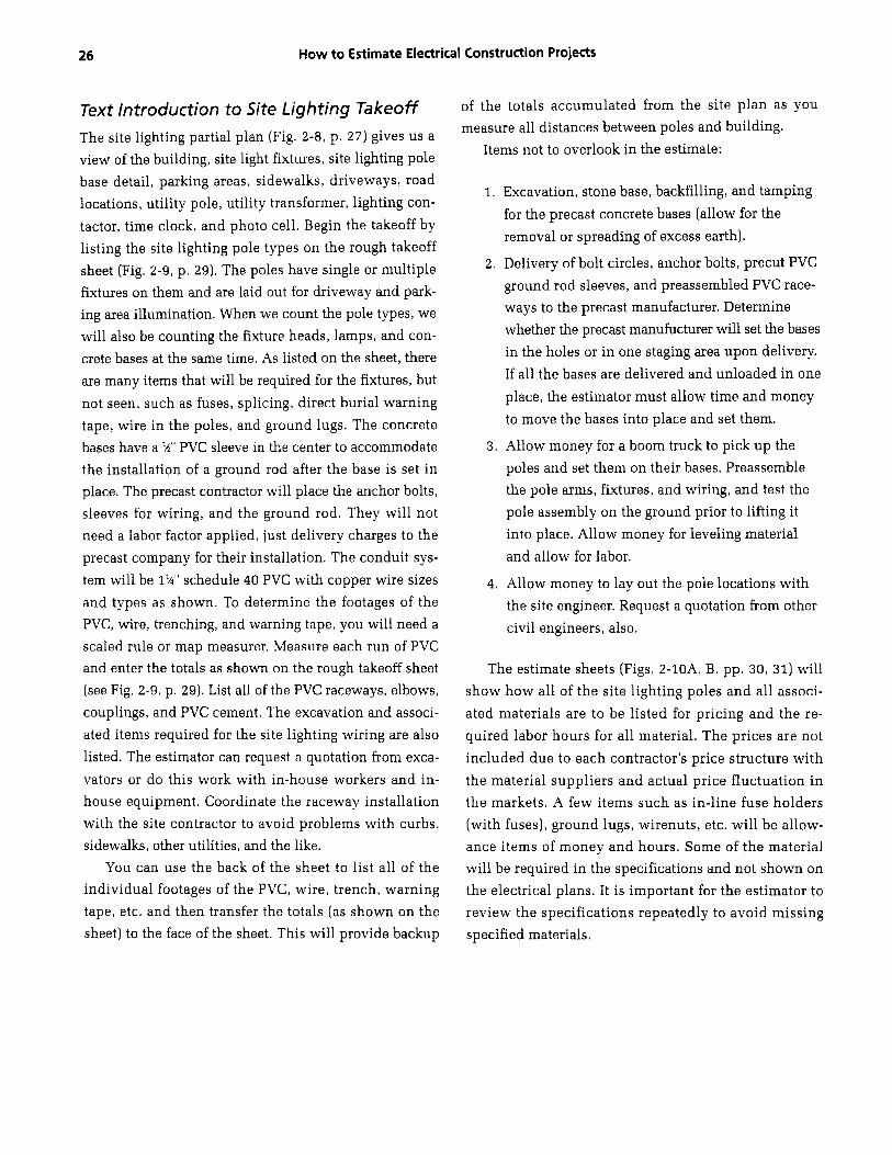
Text Introduction to Site Lighting Takeoff The site lighting partial plan (Fig. 2-8, p. 27) gives us a view of the building, site light fixtures, site lighting pole base detail, parking areas, sidewalks, driveways, road locations, utility pole, utility transformer, lighting con- tactor, time clock, and photo cell. Begin the takeoff by listing the site lighting pole types on the rough takeoff sheet (Fig. 2-9, p. 29). The poles have single or multiple fixtures on them and are laid out for driveway and park- ing area illumination. When we count the pole types, we will also be counting the fixture heads, lamps, and con- crete bases at the same time. As listed on the sheet, there are many items that will be required for the fixtures, but not seen, such as fuses, splicing, direct burial warning tape, wire in the poles, and ground lugs. The concrete bases have a $9' PVC sleeve in the center to accommodate the installation of a ground rod after the base is set in place. The precast contractor will place the anchor bolts, sleeves for wiring, and the ground rod. They will not need a labor factor applied, just delivery charges to the precast company for their installation. The conduit sys- tem will be 1%'' schedule 40 PVC with copper wire sizes and types as shown. To determine the footages of the PVC, wire, trenching, and warning tape, you will need a scaled rule or map measurer. Measure each run of PVC and enter the totals as shown on the rough takeoff sheet (see Fig. 2-9, p. 29). List all of the PVC raceways, elbows, couplings, and PVC cement. The excavation and associ- ated items required for the site lighting wiring are also listed. The estimator can request a quotation from exca- vators or do this work with in-house workers and in- house equipment. coordinate the raceway installation with the site contractor to avoid problems with curbs, sidewalks, other utilities, and the like.
You can use the back of the sheet to list all of the individual footages of the PVC, wire, trench, warning tape, etc. and then transfer the totals (as shown on the sheet) to the face of the sheet. This will provide backup
of the totals accumulated from the site plan as you measure all distances between poles and building.
Items not to overlook in the estimate:
1. Excavation, stone base, backfilling, and tamping for the precast concrete bases (allow for the removal or spreading of excess earth).
2. Delivery of bolt circles, anchor bolts, precut PVC ground rod sleeves, and preassembled PVC race- ways to the precast manufacturer. Determine whether the precast manufucturer will set the bases in the holes or in one staging area upon delivery. If all the bases are delivered and unloaded in one place, the estimator must allow time and money to move the bases into place and set them.
3. Allow money for a boom truck to pick up the poles and set them on their bases. Preassemble the pole arms, fixtures, and wiring, and test the pole assembly on the ground prior to lifting it into place. Allow money for leveling material and allow for labor.
4. Allow money to lay out the pole locations with the site engineer. Request a quotation from other civil engineers, also.
The estimate sheets (Figs. Z-lOA, B, pp. 30, 31) will show how all of the site lighting poles and all associ- ated materials are to be listed for pricing and the re- quired labor hours for all material. The prices are not included due to each contractor's price structure with the material suppliers and actual price fluctuation in the markets. A few items such as in-line fuse holders (with fuses), ground lugs, wirenuts, etc. will be allow- ance items of money and hours. Some of the material will be required in the specifications and not shown on the electrical plans. It is important for the estimator to review the specifications repeatedly to avoid missing specified materials.

EST. NO: 1 O/O1/03-1 SITE LIGHTING JOB: Office bldq #lo0 Utown, USA
SITE LIGHTING PARTIAL PLAN SHEETNO: 1 OF 1 DATE: 10/01/03 -
Primary electric service to xfm'r Communications conduit to building See site services plan for details ..... .....
I ...... A ............... d P w r ' co' transf'
6-pole Igt contactor 30a 480v & Time clock for outside lighting
Pwrl Co. Term Pole
2#8 & 1#10 in 1
. *.
2#0 1#10 in 1 1/epvc -$
Type 3
-
2#6 & 1#10 in 1 1/4"pvc
Type 1
- G * -
2#8 &1#10 in 1 1/4"wc
-f. Type 1 +
I'
. I
OFFICE BUILDING
' I
I NOTTOSCALE
SITE LIGHT POLE BASE DETAILS anchor bolt ca e *and rd sleve
1 /e! \ 3,' I
typical conduit space as reqd
NOTE: Anchor bolt size & circle will be per pole mfg' spec's.
Figure 2-8 N U

28 How to Estimate Electrical Construction Projects
NOTES
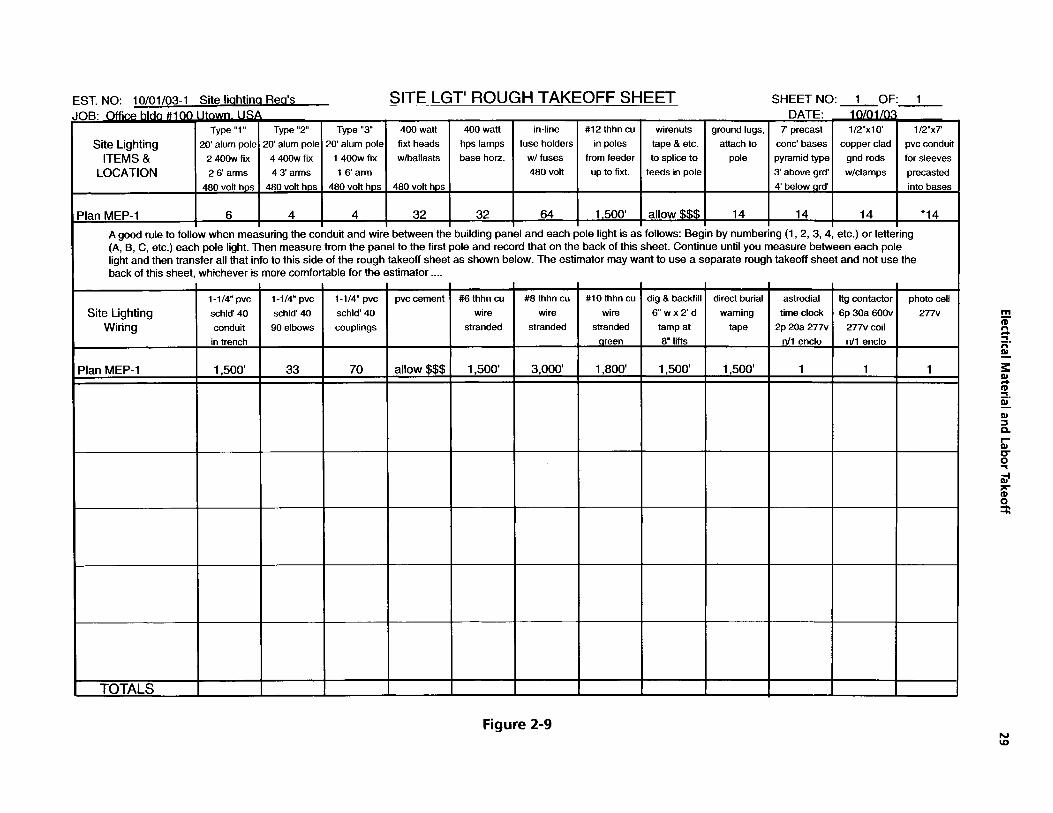
Type "1" Type "2" Type " 3 400 wan 400 wan in-line #12 thhn cu wirenuts ground lugs, 7' precast 1/2"x10 1/2"x7' Site Lighting 2 0 alum pole 2 0 alum pole 20' alum pole fixt heads hps lamps fuse holders in poles tape & etc. attach to conc' bases copper clad pvc conduit
ITEMS & 2 40Ow fix 4 40Ow fix 1 400w fix w/ballasts base horz. w/ fuses from feeder to splice to pole pyramid type gnd rods for sleeves LOCATION 26arms 43'arms 16'arm 480 volt up to fixt. feeds in pole 3 above grd' w/clamps precasted
480 volt hps 480 volt hps 480 volt hps 480 volt hps 4' below ard' into bases
Plan MEP-1 6 4 4 32 32 64 1.500 allow $$$ 14 14 14 *14
A good rule to follow when measuring the conduit and wire between the building panel and each pole light is as follows: Begin by numbering (1, 2, 3, 4, etc.) or lettering (A, B, C, etc.) each pole light. Then measure from the panel to the first pole and record that on the back of this sheet. Continue until you measure between each pole light and then transfer all that info to this side of the rough takeoff sheet as shown below. The estimator may want to use a separate rough takeoff sheet and not use the back of this sheet, whichever is more comfortable for the estimator ....
Figure 2-9
astrodial time clock
2p 20a 277v n/l enclo
1
N W
Itg contactor photo cell 6p 30a 600v 277v
277v coil n/l enclo
1 1

30 How to Estimate Electrical Construction Projects
ESTIMATE SHEET ESTIMATE NO: 10/01/03-1
JOB: Office bldg' #lo0 Utown, USA PAGENO: 1 OF 2 Estimate Sheet of Site Linhtina Labor Hours
ESTIMATED BY: Mr. E S T . CHCK'D BY: Sr. DATE: 10/01/03
Figure 2-10A

Electrical Material and Labor Takeoff 31
ESTIMATE SHEET ESTIMATE NO: 10/01/03-1
JOB: Office bldg' #lo0 Utown, USA PAGENO: 2 OF 2 Estimate Sheet of Site Lighting Labor Hours
ESTIMATED BY: Mr. E.S.T. CHCKDBY: Sr. DATE: 10/01/03
1
2
3
4
5
6
7
8 #lo thhn 600v copper wire stranded 1,800' M 10 M 18
9
10 Direct buried electrical lines warning tape 1,500' M 4 M 6
I 1
12
13
14
15
16
17
18
19
20
21
22
23
24
25
26
27
28
29
30
31
32
Figure 2-10B

32 How to Estimate Electrical Construction Projects
Text Introduction to Branch Wiring Takeoff In order to takeoff the branch wiring, you need to refer to a few of the electrical plans. On the lighting plan (see Fig. 2-2B) you will find the circuiting for the lighting fix- tures and for the associated switching of these fixtures. On the devices plan (see Fig. 2-5) you will find the cir- cuiting for the receptacles and the 120 V feed to the fire alarm control panel from the RP panel. In our example here, MC cable is permitted on this project for all branch wiring within the building. There is no wiring in the floor, as it had been poured prior to the contracts being awarded. There may be a need to install a short amount on EMT in the utilities and restrooms (less than 50 feet), but we will make an allowance for this small amount of EMT and wire required. On the branch wiring rough takeoff sheet (Fig. 2-11, p. 33), the MC cable and associ- ated fittings have been listed according to the plan num- ber. As described above, we takeoff the material and list it according to the plan number, which serves as a check that a plan was not overlooked in the takeoff procedure.
The estimate sheet (Fig. 2 -12 , p. 34) will show how all of the branch circuit wiring and associated materials are to be listed for pricing and the hours required for each item. The prices are not included due to each con- tractor’s price structure with the material suppliers and actual price fluctuation in the markets. A few items such as wall stud sleeves, splicing materials, tape, tags, junction boxes, etc. will not be shown on the plans, but will be required. It is important for the estimator to visualize the installation of the cable and listing the material and labor allowances in the estimate.
Text Introduction to Communications Takeoff The partial communication floor plan (Fig. 2-13, p. 35)
shows the communications equipment for the voice and data wiring required. The voice backboard and 110-punch-down block are located in the utilities room.
The data patch panel floor stand with the patch panel are also located in the utilities room. There are three locations that have a combination voice and data outlet. These three outlet locations will require one category # 3 plenum-rated cable for voice and one category #5
plenum-rated cable for data. Both cables will terminate in the utilities room on their respective voice block or data panel. The outlets at the wall will consist of one single-gang wall box, one voice connector, one data connector, and one single-gang combination wall plate to accommodate both voice and data connectors. The single-voice outlet in the utilities room will require an outlet box, a voice connector, and a single wall plate. As you can see on the floor plan, the cables run to- gether through the suspended ceiling from the outlet to the utilities room. These cables will be supported by “J” hooks and through the wall sleeves as required at all penetrations. Patch cords are provided for both voice and data. All cables, plates, blocks, and panels will be tagged with the appropriate markings. Field testing must be performed on all cables and a record of the tests turned over to the proper authority. All penetra- tions of walls and partitions require sleeves to accom- modate the voice and data cables. The estimator must count and list all the components required for the voice/ data system on the rough takeoff sheet (Fig. 2-14, p. 37).
The estimate sheet (Fig. 2-15, p. 38) will show how all of the communication items and the associated mate- rials are to be listed for pricing and the required labor hours. The prices are not included due to each contrac- tor’s price structure with the material suppliers and actual price fluctuation in the markets. As listed above, many materials for the communication system are not shown on the plans but will be necessary for a complete system. Some of these materials may be patch cables, grounding, a cable support system, labels, testing, etc. The specifications will also specify the various compo- nents required for a complete communication system.

Figure 2-1 1
SHEETNO: 1 OF: 1 DATE: 1 0/01/03
SPLICING WALL STUD 4 & 5” TAPE SLEEVES SQ‘ BOXE! TAGS Wl BLANK
COVERS
ALLOW I 40 I 25
ALLOW I 50 I 25
ALLOW I 90 I 50
W W

34
1
2
3
4
5
6
7
a 9
How to Estimate Electrical Construction Projects
2/c #12 MC cable 3,000 3/c #12 MC cable 1,000 4/c #12 MC cable 400'
2/c #10 MC cable 100'
3/c #10 MC cable 300'
4/c #lo MC cable 750'
MC cable connectors 374
MC cable hangers and SupportsMastners Allow
ESTIMATE SHEET
10
11
ESTIMATE NO: 10/01/03-1
I I
Metal stud wall sieves 90 I
JOB: Office bldg' #lo0 Utown, USA PAGENO: 1 OF 1 Estimate Sheet of Branch Wirinq Labor Hours
ESTIMATED BY: Mr. F S.T. CHCKDBY Sr. DATE: 10/01/03
I DESCRIPTION OF MATERIALS MATERIA1 QUANTITY I UNITCOST
121 I- 13 4" and 5" square boxes with blank covers I 50 14 I I
I
15 Misc. splicing, tags, tape, ty-raps, etc. Allow
16 I I
17 Allowance for misc' EMT and wire I Allow I i a 19
20
21
25
26 I I
30 2gk 32 I I M = Per Thousand EA = Each
36
55
I I -
I I -
15
M 41.25
I
I
1
2
3
4
5
6
7
8
9
10
11
12
13
14
15
16
17
i a 19
20
21
22
23
24
25
26
27
28
29
30
31
32
I C = Per Hundred TOTAL I I TOTAL 1 324.35
Figure 2-12

Electrical Material and Labor Takeoff
35
-
3 c .-..-.--I
t
I I I i I I I I I @
\ *,
\ \ \ /
L

36 How to Estimate Electrical Construction Projects
NOTES

EST. NO: 10/01/03-1 VOICE-DATA COMM' ROUGH TAKEOFF SHEET
VD data
wall outlet box & plate & connector
0
voice cable punch down
at 110 block
4
v w D voice/data I-IHP telephone 64 pori I - shelf for wall outlet voice/data patch panel data patch patch panel box & plate backboard floor stand panel 8 wire mng'r I connectors 4x8' & qnd conn
3 1 1 1 1
cat' 5 cat' 3 'J' hooks test all data cable voice cable for cables cables
**.. *.**
plenum plenum 3x1 00 4x1 00
*..e
.*.a
m e $. E 3 2 %. E P 3 P
0 5 4 d x e 0 3
Figure 2-14 W U

38 How to Estimate Electrical Construction Projects
ESTIMATE SHEET ESTIMATE NO: 10/01/03-1
JOB: Office bldd #lo0 Utown, USA PAGENO: 1 OF 1 Estimate Sheet of Communications Labor Hours
ESTIMATED BY: Yr. F S.T. CHCKDBY: Sr. DATE: 10/01/03
C = Per Hundred PR = Per Pair TOTAL I TOTAL 27.9
Figure 2-15

Electrical Material and Labor Takeoff 39
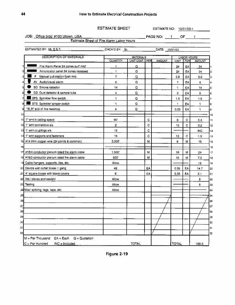
Text Introduction to Fire Alarm Takeoff The fire alarm partial floor plan (Fig. 2-16, p. 40) lays out the fire alarm devices required for this portion of the building. The typical fire alarm riser diagram (Fig. 2-17, p. 42) provides the estimator with the wiring and zones required. The main fire alarm panel is located in the utility room along with the sprinkler flow and tamper switches. The remote annunciator panel should be located near the entrance to give the first responders the immediate location that initiated the alarm. The duct detectors will be mounted on the HVAC duct work in accordance with the local authorities’ codes. The length of the sampling tubes for the detector will need to be measured after a location has been determined. Coordinate the installation of the tube and detector with the HVAC duct installer. The estimator should ver- ify the wiring requirements and device quantities for each zone with the fire alarm equipment supplier. The detector zones may incorporate manual stations as well as automatic detectors. The estimator should request a floor plan from the fire alarm equipment supplier show- ing the locations of the devices, wiring, and zones. Here again we list all of this material on the rough takeoff sheet (Fig. 2-18, p. 43).
The estimate sheet (Fig. 2-19, p, 44) will show all of the fire alarm system materials and associated items that are to be listed for pricing and the required labor hours for all the material. The prices are not included due to each contractor’s price structure with the mate- rial suppliers and actual fluctuation in the markets. There are various items that are not shown on the plans but will be required for a complete fire alarm system; some of these may be junction boxes, hangers and sup- ports, wall sleeves, splicing materials, and labels and tags. The estimator will find that the specifications will specify many of these items, but not all; the estimator must allow for these unseen items.
Text Introduction to Mechanical Equipment Takeoff Sheet Allow for splicing, tagging, tape, testing, etc. Locate the ATC panel and furnish it with a 120 V circuit (Fig. 2-20,
p. 45). All automatic temperature control wiring is to be furnished and installed by the HVAC contractor. All motor controllers and controls are to be furnished by the HVAC contractor. The electrical contractor shall receive, mount, and wire line the voltage wiring of starters. Coordinate all wiring and installations with the HVAC contractor. Here again we list all of this mate- rial on the rough takeoff sheet (Fig. 2-21, p. 47).
The estimate sheet (Fig. 2-22, p. 48) will show how all of the mechanical equipment requirements are listed for pricing and the required labor hours for the project. The electrical contractor will be responsible for certain items in accordance with the plans and specifications.
The estimator will need to go back through the HVAC specifications and read what that contractor is to furnish (e.g., fans, rooftop HVAC units, etc.). Coordi- nate this information with the electrical specifications. If there are any conflicts, seek clarifications prior to bid submission.
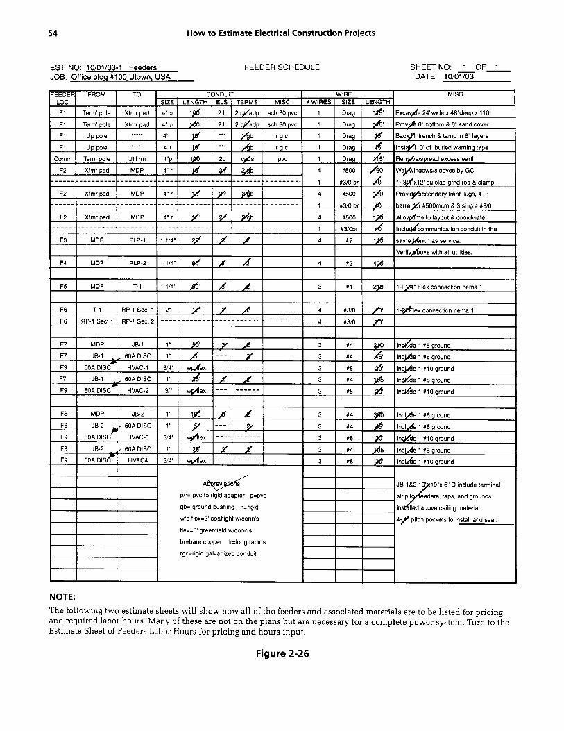
Text Introduction to Services to Building, Feeders, Panels, and Transformers The following partial floor plans and estimate sheets (Figs. 2-23-2-27B, pp. 49-56) include the utility serv- ices to the building, the main service electrical equip- ment, the electrical panels, and the feeders to the elec- trical panels and HVAC equipment. The typical power riser diagram on this page depicts the feeders to the var- ious panels, the transformer, and mechanical equip- ment. The estimator should review this riser and list the feeders shown on a feeder schedule (Fig. 2-26, p. 54), which is included herein. Take note that all of the interior feeders will be installed above the suspended ceiling and exposed in the utilities room. The raceways outside of the building walls are installed underground, as shown on the riser. The panels and transformer are shown here as well as the mechanical equipment.

40 H
ow to Estim
ate Electrical Construction Projects
3 a 0
5 a 1
LL
F
U a a H 9 a a
E
w
D
--v
I
i I I i i i \ \ \ \ ).
\ / n
0 ,
b - .- C

Electrical Material and Labor Takeoff
NOTES
41

EST. NO: 10/01/03-1 (FIRE ALARM) TYPICAL FIRE ALARM RISER DIAGRAM JOB: Office bldg #lo0 Utown, USA
SHEETNO: 1 OF: 1 DATE: 10/01/03
SYMBOLS: A= 4/c #16 plenum rated fire alarm cable B= 2/c #16 plenum rated fire alarm cable FA= manual pull station; mount on recessed wall box VH= visual & audio alarm; mount on recessed wall box SD= ceiling mounted smoke detector; mount on ceiling outlet box DD= duct mounted detector w/ sample tube mounted in retum duct (keep distance from all duct bends, see specs) The flow and tamper switches are furnished & installed by others. NOTE:
Figure 2-17
Next Page

EST. NO: 10/01/03-
1,500' Plan E-3
12 coup's 1 common 14 clamDs (25x1 00)
500' 42 allowance allowance allowance allowance 90' 2,500'
TOTALS
FIRE ALARM ROUGH TAKEOFF SHEET SHEETNO: 1 OF: 1
Figure 2-18
Previous Page
44 How to Estimate Electrical Construction Projects
ESTIMATE SHEET ESTIMATE NO: 10/01/03-1
JOB: Office blda' #lo0 Utown, USA PAGENO: 1 OF 1 Estimate Sheet of Fire Alarm Labor Hours
ESTIMATED BY: Mr. F S.T. CHCK'D BY Sr. DATE: 10/01/03
Figure 2-19

EST. NO: 10/01/03-1 MF(3-I' FQUIP' LAYOUT JOB: Office blda #lo0 Utown. USA
MECH EQ PARTIAL FLOOR PLAN
Mount all motor controls in utility room
SHEETNO: 1 OF 1 DATE: 10/01/03
I I L4 #12s
Panel PLP-1
'. ' J
i I i i
NOTES: All motor controls shall be furnished by the HVAC contractor and turned over to the electrical contractor for installation and power wiring. (All ATC wiring to be furnished and installed by the HVAC contractor.) All exhaust fans are to be furnished with electric power safety disconnect devices. All motor controllers shall be furnished with the proper-sized overload heaters. The HVAC contractor shall furnish and install all equipment supplied, except as noted otherwise.
Figure 2-20

46 How to Estimate Electrical Construction Projects
NOTES

EST. NO: 10/01/03-1 MECHANICAL EQUIP' ROUGH TAKEOFF SHEET
Figure 2-21
SHEETNO: 1 OF: 1

48 How to Estimate Electrical Construction Projects
ESTIMATE SHEET ESTIMATE NO: 10/01/03-1
JOB: Office bldg' #lo0 Utown, USA PAGENO: 1 OF 1
Estimate Sheet of Mechanical Equipment Labor Hours ESTIMATED BY: F S.T. CHCKDBY: Sr. DATE: 10/01/03
EA= Each
FIBO= Furnished & Installed by Others TOTAL TOTAL 38.15
Figure 2-22

EST. NO: 10/01/03-1 (FEEDERS) TYPICAL POWER RISER DIAGRAM JOB: Office blda #lo0 Utown, USA
SHEET NO: 1 OF: 1 DATE: 10/01/03
Feel
Roof Line
**
trans'fr
Exterior building wall . _ _ _ ~ NOT TO SCALE ;-El Y- er # "F-l"= 2- 4" Schld 80 pvc conduits in trench for power co. feeder. Use galv' UR sweep ells. Install drag lines. Min' bury @ 4 8 b.f.g.
'F-2"= 3- 4" Rigid galv' conduits in trench for secondary service to bldg' each with 4 #500 mcm thhn copper cables and 1 #3/0 bare copper "F-3"= 1 1/4" c with 4 #2 awg thhn copper cables "F-4"= 1 1/4" c with 4 #2 awg thhn copper cables "F-5"= 1 1/4" c with 3 #1 awg thhn copper cables "F-6"= 2" c with 4 #3/0 awg thhn copper cables "F-7"= 1" c with 3 #4 8 1 #8 awg thhn copper cables "F-8"= 1" c with 3 #4 8 1 #8 awg thhn copper cables "F-9= 3/4" c with 3 #8 8 1 #10 awg thhn copper cables
* = 60 amp- 600 volt- no fuse- w/p disc. (w/gnd lug) + = Jbox w/ term' block for feeders, taps 8 gnds. =k= Ground to building steel
= Roof pitch pocket furnish and install & = Foundation wall seal sleeves for feeders Note: See plans for all panel schedules, transformer, etc.
Notes: Trenching, backfill, tamping, sand layers, burial warning tape, excess earth removal and layout by the EC. Foundation wall sleeves/windows for all electrical penetrations to be furnished and installed by the GC. The EC to coordinate all locations. EC to coordinate location and requirements with the utility company on their transformer, pad, and grounding. EC to check with the local inspection authority on the grounding requirements for the electrical equipment.
**
Figure 2-23

50 How to Estimate Electrical Construction Projects
ESTIMATE SHEET ESTIMATE NO: 10/01/03-1
JOB: Office bldq' #lo0 Utown, USA PAGENO: 1 OF 2 Estimate Sheet of Panels & Transformers Labor Hours
ESTIMATED BY: F S T. CHCK'D BY: Sr. DATE: 1OlOl lO3
1
2
3
4
5
6
7
8
9
1 10
1 11
1 12
1 13
1 14
15 1
16 1
17 1
18 1
19 1
20 2
21 2
22 2
23 2
24 2
25 2
26 2
27 2
20 2
29 2
30 3
31 3
32 3
Figure 2-24A

Electrical Material and Labor Takeoff 51
ESTIMATE SHEET ESTIMATE NO: 10/01/03-1
JOB: Office bldg' #lo0 Utown, USA PAGENO: 2 OF 2 Estimate Sheet of Panels & Transformers Labor Hours
ESTIMATED BY: Mr. F S.T. CHCKD BY: Sr. DATE: 10/01/03
AL = Allowance TOTAL I I TOTAL I 38.1
1
2
3
4
5
6
7
8
9
10
11
12
13
14
15
16
17
18
19
20
21
22
23
24
25
26
27
28
29
30
31
32
Figure 2-24B

EST. NO: 10/01/03-1 SFRVICFS 1 AYOUT SITE SERVICES PARTIAL PLAN JOB: Office bidq #lo0 Utown. USA
SHEETNO: 1 OF 1 DATE: 10/01/03 r-------------- I Trench 24"w x 48"d to terminal pole I
Staging area
for power & comm's.
NOTE: 1- Verify all requirements for both power and communications with all agencies prior to installations! 2- Review specs for all requirements on the materials for installation and the power riser diagram.
1-4" PVC to pole for
3- 4" RGC ea w/ 4 #500 mcm cu
I 2 -4 PVC conduits o utility terminal pole
for power & comm's.
, \""' below finish grade '. Staging area I Locate temp srvs here &
I office/storage trailers here 1- . '
3- 4" RGC ea w/ 4 #500 mcm cu
I l l
I I
\
'. ' '.
/ IHVAC-']
The electrical service and secondary conduits and wire are listed on the feeder sheet rough takeoff. Also included is the communications empty conduit. All of the panel and mechanical equipment feeders, the subcontracting, asso- ciated material, and labor are shown here also. From this feeder sheet rough takeoff the materials listed are trans- ferred to the estimate sheets (2) for pricing and the required labor hours.
PLP-2 RP-112 -- ["""-"j I
0. -. 4. I -. i 0. -. ' 0- - a \ .
'---. -.
NOT TO SCALE
'. '.
*'/*
Figure 2-25

Electrical Material and Labor Takeoff
NOTES
53
54 How to Estimate Electrical Construction Projects
EST. NO: 10/01/03-1 Feeders JOB: Office blda #lo0 Utown. USA
FEEDER SCHEDULE SHEETNO: 1 OF 1 DATE: l O / O x
p/r= pvc to rigid adapter p=pvc
gb= ground bushing r=ngid
w/p flex=3 sealtight wiconn's
f l e x 3 greenfield w/conn s
br=bare copper Ir=long radius
rgc=ngtd galvanized conduit
4.)" pitch pockets to install and seal.
NOTE: The following two estimate sheets will show how all of the feeders and associated materials are to be listed for pricing and required labor hours. Many of these are not on the plans but are necessary for a complete power system. Turn to the Estimate Sheet of Feeders Labor Hours for pricing and hours input.
Figure 2-26

Electrical Material and Labor Takeoff
ESTIMATE SHEET
55
ESTIMATE NO: 10/01/03-1
JOB: Office bldd #lo0 Utown, USA PAGENO: 1 OF 2 Estimate Sheet of Feeders Labor Hours
ESTIMATED BY: Mr. E.S.T. CHCKDBY: Sr. DATE: 10/01/03
I I EA = Each M = Per Thousand Q = Quotation 1 I C = Per Hundred AL = Allowance TOTAL I I TOTAL I 117.5
Figure 2-27A

56
w
- - -
-
How to Estimate Electrical Construction Projects
1
2
3
4
5
6
7
0
9
10
11
12
13
14
15
16
17
10
19
20
21
22
23
24
25
26
27
28
29
30
31
32
ESTIMATE SHEET ESTIMATE NO: 10/01/03-1
32
JOB: Office blda' #lo0 Utown, USA PAGENO: 2 OF 2 Estimate Sheet of Feeders Labor Hours
I I I I EA = Each
C = Per Hundred TOTAL TOTAL 81.75
M = Per Thousand
ESTIMATED BY Mr. F S.T. CHCKDBY Sr. DATE: 10/01/03
Figure 2-27B

EST. NO: 10101/03-1 TYPICAL DETAILS ROUGH TAKEOFF SHEET SHEETNO: 1 OF 2 #loo DATE: 1o/01/03-
TYPICAL WALL MOUNTED FIXTURE DETAIL (EXTERIOR) TYPICAL WALL MOUNTED FIXTURE DETAIL (INDOOR) ( Metal Stud wlsheetrock 2 sides )
Concrete block wall
& One gang Masonry wall box wall -
MC cable or EMT
4" sq' JB in bldg' ceiling space
EMT short nipple wlconn's. Provide sealant I caulking as req'd. Typical anchor FSl
EMT (or MC cable in interior walls) Outlet box, device, plate (typ) Switch, recept', other devices Height as spec'd.
DETAIL 1
TYPICAL LAY-IN FIXTURE Structural bar ioist
Suspended t-bar system 4- supportwires
T-bar T-bar
J - Hold-dohn clip Light fixture Hold-down cbp
DETAIL 3
Suspended acoustic ceiling tile
+ MC cable or emt /
g dry wall box & bar support
.,Added supports if req'd.
M or MC cable
Outlet box, device, plate (typ') Switch, recept', other devices Height as spec'd.
DETAIL 2
TYPICAL RECESSED HI-HAT TYPE FIXTURE Structural bar ioist
- . _ n
,4- safety wire I Suspend d t-bar system e support wires -b ' G e x i b l e I
t Recessed light fixture
DETAIL 4
Figure 2-28A VI U

EST. NO: 10/01/03-1 TYPICAL DETAILS ROUGH TAKEOFF SHEET SHEETNO: 2 OF: 2 1 , DATE: -03
Typical suspended light fixture support
Conduit & j-box for branch circuit
Fluorescent light fixture
Typical lighting panel with main lugs only
0
0
0
A 0 B 0 C 0
Neutral
0
0
0
Typical detail of recept' & "M" fixture on roof and typical roof pitch pocket for conduit penetrations
+Type "M' fixture
1 rigid conduit
1 " cast outlet box + /P GFCl 11W x 1' bell reducer ir- T ical pitch pocket & sealant
k
Secure frame to roof -*Angle iron welded frame for support rigid conduit & roof devices
lamp conduit as req'd.
Connect to circuit conductors J-box
Typical panel interior with main circuit breaker and feed thru lugs circuit breaker
Figure 2-28B

Electrical Material and Labor Takeoff 59
Rough Takeoff Sheets to Estimate Sheets Now that we have listed all electrical devices, light fix- tures, service equipment, raceways, and wire on the rough takeoff sheets, we move all of the items from the rough takeoff sheets to the estimate sheets for material pricing and labor rates (Figs. 2-29A-P, pp. 61-77).
Figure 2-29D, p. 65, lists the materials and work re- quired for the empty conduits for the utility company feeders and the communications for the project, trans- former pad requirements, secondary feeders to the MDP in the building, excavation, grounding, etc. This infor- mation was gathered from the feeder schedule for the project (see Fig. 2-26, p. 54).
Here we see the PVC raceways, the excavation re- quirements, rigid conduits up the terminal pole, drag lines, grounding, direct burial warning tape, utility com- pany transformer pad requirements, and all conduit fit- tings. On the feeder schedule (see Fig. 2-26, p. 54) we listed the material required. The estimate sheet allows the estimator to list all the items and apply pricing and labor hours necessary for their purchase and their installation. In order to apply the labor hours for all the materials the estimator will need a reliable labor unit reference manual such as the labor rates included in this book.
Figures 2-29E-F, pp. 66-67, list the service equip- ment, panels, transformers, grounding, etc. This infor- mation was gathered from the riser and plan of the proj- ect. On the feederlriser and panel schedule (see Fig. 2-23, p. 49) we listed all of the materials onto another estimate sheet (or sheets). The format for the estimate sheets listing this equipment allows the estimator to apply labor to each item as needed. Project specifica- tions will describe all of the equipment details.
Figure 2-29G, p. 68, lists feeders that service distribu- tion equipment, transformers panels, and the mechanical equipment. This information was gathered from the riser and panel schedule of the estimate (see Fig. 2-23, p. 49).
On the feeders one-line diagram (see Fig. 2-23, p. 49) we listed all the conduit, cable, junction boxes, flex, etc. onto another estimate sheet. There will be items required such as hardware, clamps, hangers, splicing materials, and lugs not seen on the plans but that must be ac- counted for in the estimate.
Figure 2-29H, p. 69, lists the materials and work re- quired for the branch circuits. This information was gathered from rough takeoff sheets of the project. On the branch wiring rough takeoff sheet (see Fig. 2-11, p. 33)
we listed all of the material onto another estimate sheet. As you can see on the estimate sheets of this estimate there are items of material not shown on the plans but necessary for a complete installation. The estimator must be aware of these types of materials and make all allowances of labor and material costs in the estimate.
Figures 2-291-7, pp. 70-71, list the site lighting poles, fixtures, wiring, etc. This information was gathered from rough takeoff sheets of the estimate. On the site lighting rough takeoff sheet (see Fig. 2-9, p. 29) we listed all of the materials onto another estimate sheet. This rough takeoff sheet lists all of the site lighting as shown on the partial site plan and all of the unseen but necessary material and labor for a complete installation.
Figures 2-29K-L, pp. 72-73, list the light fixtures, lamps, whips, boxes, etc. This information was gathered from rough takeoff sheets of the estimate. On the fixtures rough takeoff sheets (see Figs. 2-3A, B, pp. 18, 19) we listed all of the materials onto another estimate sheet (or sheets). There are a few allowances that must be included here again. The estimator should be aware of the unseen material and any associated labor hours necessary for a complete installation and include them in the estimate.
Figure 2-29M, p. 74, lists the devices, boxes, and plates. This information was gathered from rough take- off sheets of the estimate. On the devices rough takeoff sheet (see Fig. 2-6, p. 24) we listed all of the materials onto another estimate sheet (or sheets).
Figure 2-29N, p. 75, lists all of the materials for a voice and data communications system. This informa- tion was gathered from rough takeoff sheets of the esti- mate, On the communications rough takeoff sheet (see Fig. 2-14, p. 37) we listed all of the voice and data out- lets, backboard, patch panel and stand, cables, patch cords, punch-down block, connectors, etc. onto another estimate sheet (or sheets).
Figure 2-290, p. 76, lists all of the materials for a fire alarm system. This information was gathered from rough takeoff sheets of the estimate. On the fire alarm rough

60 How to Estimate Electrical Construction Projects
takeoff sheet (see Fig. 2-18, p. 43) we listed the fire alarm panel, annunciator, stations, signals, detectors, resistors, flow and tamper switches, cable, boxes, raceways, wire, etc. onto another estimate sheet (or sheets).
Figure 2-29P, p. 77 , lists all of the materials required for the mechanical equipment. This information was gath- ered from rough takeoff sheets of the estimate. On the mechanical equipment takeoff sheet (see Fig. 2-21, p. 47)
we listed the various items furnished by the electrical con- tractor and the mechanical equipment that requires elec- trical connections onto another estimate sheet (or sheets).
NOTE: As the estimate sheets are developed a page number should be placed on them. This will help the estimator to keep track of how many pages there are and will reduce the loss of a sheet. If they are numbered sequentially, a missing estimate sheet will be avoided. The sequence of the pages can be adjusted and when doing so the number should also be changed to match the sequence (some use the A, B , C, etc. method then change to numerals).
The next step is to assemble all of the estimate sheets in numerical order and begin to apply the prices and labor hours to all of the materials and necessary allowances where they are needed. In order to apply the labor rates, the estimator will need a labor rate reference guide to refer to. This book contains a section devoted to material labor rates used herein (see Chapter 3) . Refer to the sam- ple estimate to see how the labor rate units are applied to the materials listed on the estimate sheets. Upon comple- tion of the individual labor units and their mathematical extensions, the sheets should be totaled.
Pricing the material and allowances on each estimate sheet is delegated to different persons in contracting companies. Some will have the estimator do it, some will have a purchasing agent do it, and some contractors will perform the task themselves. No matter who does the pricing of the material, the estimator should be the one responsible for assembling the estimate sheets after all of the labor hours and prices are completed and to- taled. All major material suppliers’ quotations should be reviewed for any exclusions, quantities, delivery dates,
shop drawings submittal dates, etc. The supplier with the lowest quotation in accordance with all of the plans and specifications should be entered into the estimate where required.
During this time frame the estimator should prepare the recapitulation of the estimate sheets. The recapitu- lation sheet (or sheets) will list all of the estimate sheets and their totals of labor hours and material (Fig. 2-29C, p. 64). Upon completion of the recapitulation sheet (or sheets) the total of the material cost (less quotations) and the total of hours will be transferred forward to the final recapitulation cover sheet (Fig. 2-29A, p. 61). Now that the material prices and the labor hours for the en- tire estimate have been entered onto the final recapitula- tion sheet, the estimator prepares the equipment prices needed recapitulation sheet (Fig. 2-29B, p. 63). On this recapitulation sheet (or sheets) the estimator enters all the quotations of the major items for the project. Such mate- rial may be the light fixtures in the building as well the site lighting, power distribution equipment, life-safety equipment, communications equipment, civil work sub- contractor, precast concrete items, etc.
Once all of the quotations have been entered onto the equipment prices needed recapitulation sheet (or sheets) and totaled, the estimator will transfer this total onto the final recapitulation sheet. On the final recapit- ulation sheet we now have all of the material prices entered and the total of the labor hours required to complete the project installation (see Fig. 2-29A, p, 61).
The final estimate in a completed form follows (see Fig. 2-29A-P, pp. 61-77). The cover recapitulation sheet includes all anticipated costs of material, labor, job ex- penses, nonproductive labor, overhead, and profit.
NOTE: You will see spaces on the estimate sheets with a “Q” and a space in the material column high- lighted (any color highlight will work here). The high- light is a reminder to the estimator that a price quote is needed. If one lump sum is received for multiple items, the estimator will enter the lump sum on that estimate sheet and write “inc.” (included) in each space that is included in the lump sum.

Electrical Material and Labor Takeoff 61
RECAPITULATION SHEET ESTIMATE NO: 10/01/03-1
JOB OFFICE BLDG' #lo0 UTOWN, USA SHEETNO: 1 OF 1
ESTIMATED BY MR. E.S.T. CHECKED BY Sr. DATE: 10/01/03
(con tin u es) Figure 2-29A

62 How to Estimate Electrical Construction Projects
RECAPITULATION SHEET (BACK) 1. THE CONTRACTOR MUST INVESTIGATE THE REQUIREMENTS OF EACH GOVERNMENT AGENCY AS IT
RELATES TO SALES TAXES ON BOTH MATERIALS AND LABOR AND INCLUDE ALL OF THESE COSTS IN EACH PROPOSAL!
2. Nonproductive labor section contains various areas of costs that are affected by noninstallation labor factors. These items may or may not apply to all proposals but remind the contractor that there may be labor costs beyond the actual labor cost associated with the project. This may also remind the contractor that there may be other items of nonpro- ductive labor cost that should be addressed in the proposal.
3. Job expense section contains important direct project-related costs. These dollar costs may or may not be applicable to each proposal submitted by the contractor. This may also remind the contractor that there may be additional job- related expenses to be considered.
4. Labor hour section allows the contractor to apply different labor rates as they may apply to the level of grade of the workers who physically install or direct the installations.
5. Taxes section allows the contractor to include such taxable items of labor as they may apply to the project. 6. Overhead section is a cost of doing business for the contractor. This cost may include insurances, office supplies,
postage, contractor’s building facility, utilities, office personnel payroll, telephone, association fees, periodicals, facil- ity maintenance, rolling stock upkeep and fuel, rental of office equipment, support programs costs, etc. Include any other costs that are fixed as they relate to the business inside the contractor’s facilities.
7. Profit is relative to the size of the proposal and the amount the contractor anticipates. 8. Bond section gives the contractor the ability to include the cost of a bid bond, performance bond, andlor payment
bonds.
Figure 2-29A continued

Electrical Material and Labor Takeoff 63
ESTIMATE SHEET ESTIMATE NO: 10/01/03-1
JOB: Office bldc1' #lo0 Utown, USA PAGENO: PN-1 OF 1
EQUIPMENT PRICES NEEDED ESTIMATED BY: MR. EST. CHCKDBY Sr. DATE: 10/01/03
I DESCRIPTION OF MATERIALS MATERIAL! QUANTllY I UNITCOST
1 Civil work EST. PAGE #67 QUOTE D 2 MDP, panels, transformer EST. PAGE #63 & 64 QUOTE D 3 Site lighting fixtures EST. PAGE #43 QUOTE D 4 Boom truck allowance EST. PAGE #43 QUOTE D 5 Civil work EST. PAGE #43 & 44 QUOTE D 6 Light fixtures EST. PAGE #33 QUOTE D
7 Fire alarm EST. PAGE #56 QUOTE D 8
12
13
14
16
17 -
211 I I
25 I I 27 26-
TOTAL
1
2
3
4
5
6
7
8
9
10
11
12
13
14
15
16
17
18
19
20
21
22
23
24
~:: ~:: 29
30
31
32
Figure 2-29B

64 How to Estimate Electrical Construction Projects
ESTIMATE SHEET ESTIMATE NO: 10/01/03-1
JOB: Office bldq' #lo0 Utown, USA PAGENO: RE-1 OF 1
RECAP OF ESTIMATE SHEETS
ESTIMATED BY: MR. E S T . CHCKDBY: Sr. DATE: 10/01/03
1 1
2 2
3 3
4 4
5 5
7 7
8 8
9 9
10 10
11 11
12 12
6 6
13 13
14 14
15 15
16 16
17 17
18 18
19 19
20 20
21 21
22 22
23 23
24 24
25 25
26 26
27 27
28 28
29 29
30 30
31 31
32 32
Figure 2-29C

Electrical Material and Labor Takeoff
ESTIMATE SHEET
65
ESTIMATE NO: 10/01/03-1
JOB: Office bldg' #lo0 Utown, USA PAGENO: 1 OF 13 Estimate Sheet of Feeders Labor Hours
ESTIMATED BY: W. E.S. T. CHCKDBY: Sr. DATE: 10/01/03
Figure 2-290

66 How to Estimate Electrical Construction Projects
ESTIMATE SHEET ESTIMATE NO: 10/01/03-1
JOB: Office bid@ #lo0 Utown, USA PAGE NO: 2 OF 13 Estimate Sheet of Panels & Transformers Labor Hours
ESTIMATED BY: Mr. F~S.T. CHCKDBY: Sr. DATE: 10/01103
Q = Quotation
AL = Allowance TOTAL TOTAL 107.8
EA = Each
Figure 2-29E

Electrical Material and Labor Takeoff 67
ESTIMATE SHEET ESTIMATE NO: 10/01/03-1
JOB: Office blda' #lo0 Utown, USA PAGENO: 3 OF 13 Estimate Sheet of Panels & Transformers Labor Hours
ESTIMATED BY: Mr. EST. CHCK'D BY: Sr. DATE: 10/01/03
IAL = Allowance TOTAL I I TOTAL I 38.1
Figure 2-29F

68
30
31
32
I
How to Estimate Electrical Construction Projects
I
EA = Each
C = Per Hundred TOTAL
M = Per Thousand
1
2
3
4
5
6
7
8
9
10
11
12
13
14
115
118
'16
'17
19
20
21
22
23
24
25
26
27
28
29
30
31
TOTAL 81.75
32
Figure 2-296

Electrical Material and Labor Takeoff 69
ESTIMATE SHEET ESTIMATE NO: 10/01/03-1
JOB: Office blda' #lo0 Utown, USA PAGENO: 5 OF 13 Estimate Sheet of Branch Wiring Labor Hours
ESTIMATED BY: Mr. E.S.T. CHCK'D BY: Sr. DATE: 10/01/03
Figure 2-29H

70 How to Estimate Electrical Construction Projects
ESTIMATE SHEET ESTIMATE NO: 10/01/03-1
JOB: Office blda' #IO0 Utown, USA PAGENO: 6 OF 13 Estimate Sheet of Site Lighting Labor Hours
ESTIMATED BY: Mr. F S.T. CHCK'D BY: Sr. DATE: 10/01/03
Figure 2-291

Electrical Material and Labor Takeoff
6
7
8
0
ESTIMATE SHEET
#6 thhn 600v copper wire stranded 1,500' M 14 M 21 6
#8 thhn 600v copper wire stranded 3,000' M 12 M 36 7
#10 thhn 600v copper wire stranded 1,800 M 10 M 18 8
1 9
71
i o 9 ,
ESTIMATE NO: 10/01/03-1
Direct buried electrical lines warning tape I 1,500' I M 4 M 6 10
I 1 I I 1 11
JOB: Office bldg' #lo0 Utown, USA PAGENO: 7 OF 13 Estimate Sheet of Site Liqhting Labor Hours
ESTIMATED BY: Mr. F S.T. CHCKDBY: Sr. DATE: 10/01/03
1 1
2 2
3 3
4 4
5
17
18
I I 17
I . 18
20
21
22
1 12
1 13
1 14
1 15
1 16
I 20
I I 21
1 - I 22
- - 24
25
I I 24
I I 25 I I
27
28
I I 27
I I 28 I I
30
31
32
Figure 2-29J
I I 30
I I 31 1 1 32
M = Per Thousand
C = Per Hundred TOTAL TOTAL 107.3
Q = Quotation

72
30
31
32
How to Estimate Electrical Construction Projects
150 WATT PAR 38FL LAMPS 1 Q 0.03 EA 0.05 30
0.4 31 70 WAlT HID HPS BD LAMPS 4 Q 0.1 EA
32
Q = Quotation
EA = Each TOTAL TOTAL 76.95
Figure 2-29K

Electrical Material and Labor Takeoff
18
19
20
73
18
19
I I 20
ESTIMATE SHEET ESTIMATE NO: 10/01/03-1
JOB: Office blda' #lo0 Utown, USA PAGE NO: 9 OF 13 Estimate Sheet of Fixtures Labor Hours
22
23
ESTIMATED BY: tytr, E.S.T. CHCK'D BY: Sr. DATE: 10/01/03
1 1
2 2
3 3
4 4
I I 22
I I 23 1 I 1
5 5
6 6
7 7
8 8
9 9
10 i n I I I ."
25
26
27
28
29
30
I I I I I I 31
32 32 I I I J
EA = Each
21.55
Figure 2-291.

74
1
2
How to Estimate Electrical Construction Projects
4.2 1 S - 20 amp 277v sinQle-pole switch 6 EA 0.7 EA
SS - 2-20amp ' I " I' 0 2 . I
ESTIMATE SHEET ESTIMATE NO: 10/01/03-1
JOB: Office bldd #lo0 Utown, USA PAGENO: 10 OF 13 Estimate Sheet of Devices Labor Hours
3
4
5
6
ESTIMATED BY: Mr. F S.T. CHCK'D BY: Sr. DATE: 10l01I03
SSS - 3-20 amp " " " 1 EA 1.4 EA 1.4 3
S3 - 20 amp 277v 3-way switch 4 EA 0.75 EA 3 4
S3S3 - 2-20 amp It 0 5
54 - 20 amp 277v 4-way switch 0 6
DESCRIPTION OF MATERIALS MATERIALS I LABORHOURS QUANTIW I UNITCOST I PERI AMOUNT I UNIT I PERI AMOUNT
I I 1 I I 1
17
18
I I 17 I Price and labor the devices with a box and plate 18
20
21
7
8
9
10
11
12
13
14
15
16
~ ~~
Metal stud wall box supports Allow INC - 20 I -71
22
23
I 1 1 I I 1 1 SI I I10
22
I 23 I I
26
27
28
29
30
31
32
EA = Each
INC = included TOTAL TOTAL 30.85
Figure 2-29M

Electrical Material and Labor Takeoff 75
ESTIMATE SHEET ESTIMATE NO: 10/01/03-1
JOB: Office bid@ #IO0 Utown, USA PAGE NO: 11 OF 13 Estimate Sheet of Communications Labor Hours
ESTIMATED BY Mr. F S.T. CHCKDBY Sr. DATE: 10/01/03
Figure 2-29N

76 How to Estimate Electrical Construction Projects
ESTIMATE SHEET ESTIMATE NO: 10/01/03-1
JOB: Office bldg' #lo0 Utown, USA PAGENO: 12 OF 13 Estimate Sheet of Fire Alarm Labor Hours
~~~ ~~~
ESTIMATED BY: Mr. F S T. CHCKDBY: Sr. DATE: 10/01/03
I C = Per Hundred INC = Included TOTAL I I TOTAL
Figure 2-290

Electrical Material and Labor Takeoff
8
9
10
77
b 0 Prepackaged HV AC rooftop units 4 FIBO- 4 EA 4 8
(3-phase 480 v w/p prewired) 9 I
I I I i n
ESTIMATE SHEET ESTIMATE NO: 10/01/03-1
JOB: Office blda' #lo0 Utown, USA PAGENO: 13 OF 13
Estimate Sheet of Mechanical Equipment Labor Hours ESTIMATED BY: Mr. E S T . CHCKD BY: Sr. DATE: 10/01/03
1 1
2 2
3 3
4 4
5 5
6 6
7 7
18
19
I 18
I 19 I I I I
I . _
32
11 (Conduit and wire, flex connections, roof pockets 11 I I I I I I
I 1 I I I I 32
EA = Each
FIB0 = Furnished & Installed by Others TOTAL TOTAL 38.15
I I I I I I 12 are included on the feeder estimate sheets.) I I I 12
13 Misc' splicing, tags, tape, testing I Allow I I I I 8 14 1 I I
I
Figure 2-29P

CHAPTER 3
Labor Rate Schedules and Forms, Charts, and Diagrams
his section contains electrical construction materi- T als and associated installation labor units along with a sample estimate of a combination office and warehouse. The estimate lays out the project in orderly steps, such as the installation of the projects incoming electric service. You should understand that in order to have service delivered to the project, a variety of elec- trical materials will be necessary. A power company will require raceways, drag lines, and grounding among related items. To prepare a coherent itemized quantity of material, you will need to review the contract docu- ments including plans, specifications and all adden- dums that may be included.
TAKEOFF: The estimator should begin the takeoff of all electrical materials required by examining all the plans including building, steel, plumbing, HVAC, elec- trical, and communications plans. Review the specifi- cations that help to describe the makeup of all the materials. After the estimator has reviewed the docu- ments, a plan should be developed and the takeoff should begin. It is recommended that each section of the project should be listed on rough takeoff sheets and be assembled by sections (see sample estimate in Chap- ter 4). Consider counting and listing all of the items that would require a specific quotation price (e.g., sw. gear, panels, transformers, disconnect switches, lighting fix-
tures, civil work, life-safety systems, voice and data systems, etc.). This facilitates returns of quotations prior to the bid date.
STEP 1: Review the fixture schedule, count the fix- tures, and list them on a takeoff sheet along with the lamps, flexible whips, hangers, hold-down clips, fix- ture outlet boxes, and miscellaneous items. This allows the estimator to visit areas of the project and it familiar- izes the estimator with the project, which will assist in the takeoff. After this section of the takeoff is on the estimate sheet, refer to the sections of the manual where the labor units are listed. Apply labor units as they relate to the fixtures listed on the estimate sheet.
STEP 2: Follow STEP 1 for the remaining sections of the project, as the sample estimate would show (see Chapter 4). NOTE: The sample estimate does not in- clude pricing, as each contractor will have their own pricing structure arrangements with their suppliers and market fluctuations.
After the estimator has compiled all of the estimate sheets they will need to be listed on a separate estimate sheet referred to as a recap of estimate sheets. Next, the estimator will need to prepare a price quotations needed sheet. This should list all of the quotations that have been received from the various manufacturers of required equipment.
79