Extension of the Concession which Allows Timber … Report - Issue 1.pdf · which Allows Timber...
48
Extension of the Concession which Allows Timber Framed Construction in Class 2 Buildings to Include Class 3 Buildings A report from the Alternative solution compliance resource for fire safe timber design project PROJECT NUMBER: PNA217-1011 DECEMBER 2011 MARKET ACCESS This report can also be viewed on the FWPA website www.fwpa.com.au FWPA Level 4, 10-16 Queen Street, Melbourne VIC 3000, Australia T +61 (0)3 9927 3200 F +61 (0)3 9927 3288 E [email protected] W www.fwpa.com.au
Transcript of Extension of the Concession which Allows Timber … Report - Issue 1.pdf · which Allows Timber...

Extension of the Concession which Allows Timber Framed Construction in Class 2 Buildings to Include Class 3 Buildings A report from the Alternative solution compliance resource for fire safe timber design project
PROJECT NUMBER: PNA217-1011
DECEMBER 2011
MARKET ACCESS
This report can also be viewed on the FWPA website
www.fwpa.com.auFWPA Level 4, 10-16 Queen Street,
Melbourne VIC 3000, AustraliaT +61 (0)3 9927 3200 F +61 (0)3 9927 3288
E [email protected] W www.fwpa.com.au

Extension of the Concession which Allows Timber
Framed Construction in Class 2 Buildings to Include
Class 3 Buildings
Prepared for
Forest & Wood Products Australia
by
Exova Warringtonfire Aus Pty Ltd

Forest & Level 4, T +61 3 E info@fW www.
PublicFrameBuildi Project © 2011 F Forest &this pubassociator informopinion, This woFWPA lobenefit acopying the CopyLimited. ISBN: 978
ResearPaul EngExova WUnit 2 409-411DandenoVictoria, Australia Report IsReport Is This is
Wood Produc10-16 Quee9927 3200 fwpa.com.aufwpa.com.au
cation: Eed Consings
t No: PNA2
Forest & Wo
& Wood Prodblication incluted with it excmation contaadvice or inf
rk is copyrigogo may be and its sourcfor other puryright Act, is
8-1-921763-3
rchers: gland, Matth
Warringtonfire
Hammond Rong 3175
a
ssue Numbessue Date: 2
not the fin
cts Australia Ln St, MelbouF +61 3 9927
u u
Extensiostruction
217-1011
ood Products
ucts Australuding merchclude all liab
ained in this formation.
ght and protreproduced
ce (Forest & rposes, whic
s prohibited w
1-1
ew Eyre e Aus Pty Ltd
Road
er: 1 24/5/2011
nal report.
Limited urne, Victoria7 3288
on of thn in Cla
Australia Lim
ia Limited (Fhantability, fitbility (includin
publication
tected undein whole or iWood Produ
ch is strictly rwithout the p
d
a, 3000
he Concass 2 B
mited. All rig
FWPA) maketness for pu
ng liability foror for any
r the Copyrin part, provucts Australireserved onlyprior written c
ession wBuildings
hts reserved
es no warranturpose or otr negligence)consequenc
right Act 196ided that it isia Limited) isy for the ownconsent of F
which As to Inc
.
ties or assurherwise. FW) in relation toes arising fr
68 (Cth). Alls not sold or s acknowledgner or license
Forest & Woo
Allows Tclude Cl
rances with rWPA and allto any opiniorom the use
l material exr used for coged. Reprodee of copyrigod Products
Timber ass 3
respect to persons
on, advice e of such
xcept the mmercial
duction or ght under Australia
i
Executive Summary This project investigated a proposed extension of the concession for Class 2 Buildings which is given in the National Construction Code (NCC) Volume One (Building Code of Australia for Class 2 to Class 9 buildings) Specification C1.1 Clause 3.10 and Clause 4.3 for Type A and Type B buildings which allows the use of combustible fire rated lightweight timber construction to also include Class 3 buildings. A literature review was performed to investigate the burning behaviour of timber and the self-protective char layer which is formed when timber is exposed to fire together with the protection provided by fire protective cladding such as plasterboard. The literature review also considered previous risk assessments on the proposed extension undertaken by Victoria University. These previous risk assessments concluded that there is no increase in risk to occupants in the compartment of fire origin due to fire rated lightweight timber construction. A conclusion of the Victoria University risk assessment report was: If it assumed that the timber frame does not contribute to the fire load there is no effect of due to the timber frame on the risk to life of the ANFO1 occupants for any of the occupancies considered. The report recommended that: If it determined that the (effective) fire load is not increased then the proposed concession be allowed in similar terms to those for Class 2 buildings. The risk assessment made no attempt to model or quantify the increase in fire severity due to the timber studs in the bounding walls and did not consider the protection of timber studs and framing by plasterboard or other fire protective linings but simply concluded that if the fire load in the room of fire origin is increased then there is an increased risk of fire spread because the fire severity will be increased. The protective nature of fire rated plasterboard is investigated in the literature review included in this report. Based on the literature review and the previous risk assessments a full scale experiment was developed which was designed to compare the severity of fires within a compartment constructed using a non-combustible fire rated steel framed system with non-combustible cavity insulation and an otherwise similar compartment constructed using fire rated lightweight timber construction with combustible insulation. The results of the experiment showed that the severity of fires within the two compartments investigated were comparable and that the timber studs, the timber joists and the combustible insulation did not increase the fire severity. This conclusion was based on a number of key measurements, including gas temperatures in the compartment, non-fire side temperatures of the fire rated bounding walls and temperature rise in a protected steel column in the centre of the room. None of these parameters indicated that the fire in the compartment constructed with timber studs in the bounding walls, timber joists in the ceiling and combustible insulation throughout was more severe than the fire in the compartment constructed with steel framing and non-combustible insulation.
1 apartments not of fire origin
ii
It should also be noted that a number of fire load surveys have shown that the fire load tends to be less for Class 3 buildings compared to Class 2 buildings. The literature review found that the fire load in Class 3 buildings was generally half the fire load in Class 2 building which provides further comfort in extending the concession to apply to Class 3 buildings. The fire load used in the experiment was based on the 95th percentile figures for Class 3 buildings. In summary it is concluded that the concession for Class 2 Buildings given in NCC Volume One Specification C1.1 Clause 3.10 and Clause 4.3 for Type A and Type B buildings which allows the use of fire rated lightweight timber construction could be extended to include Class 3 buildings without an increase in risk to life. Based on the test results the concession can also be extended to permit combustible insulation in timber framed walls. Prior to the NCC being amended this research may be used to support Alternative Solutions for fire rated lightweight timber construction in Class 3 buildings.

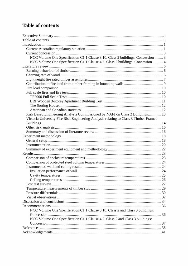
Table of contents Executive Summary .................................................................................................................... i Table of contents ........................................................................................................................ ii Introduction ................................................................................................................................ 1
Current Australian regulatory situation .................................................................................. 1 Current concession ................................................................................................................. 3
NCC Volume One Specification C1.1 Clause 3.10. Class 2 buildings: Concession ......... 3 NCC Volume One Specification C1.1 Clause 4.3. Class 2 buildings: Concession ........... 4
Literature review ........................................................................................................................ 6 Burning behaviour of timber .................................................................................................. 6 Charring rate of wood ............................................................................................................ 6 Lightweight fire rated timber assemblies ............................................................................... 7 Contribution to fire load from timber framing in bounding walls ......................................... 9 Fire load comparison ............................................................................................................ 10 Full scale fires and fire tests ................................................................................................. 10
TF2000 Full Scale Tests ................................................................................................... 10 BRI Wooden 3-storey Apartment Building Test .............................................................. 11 The Sorting House ............................................................................................................ 12 American and Canadian statistics .................................................................................... 12
Risk Based Engineering Analysis Commissioned by NAFI on Class 2 Buildings .............. 13 Victoria University Fire Risk Engineering Analysis relating to Class 3 Timber Framed Buildings .............................................................................................................................. 14 Other risk analysis ................................................................................................................ 16 Summary and discussion of literature review ...................................................................... 16
Experiment methodology ......................................................................................................... 18 General setup ........................................................................................................................ 18 Instrumentation ..................................................................................................................... 20 Summary of experiment equipment and methodology ........................................................ 22
Results ...................................................................................................................................... 23 Comparison of enclosure temperatures ................................................................................ 23 Comparison of protected steel column temperatures ........................................................... 24 Instrumented wall and ceiling results ................................................................................... 24
Insulation performance of wall ........................................................................................ 24 Cavity temperatures .......................................................................................................... 25 Ceiling temperatures ........................................................................................................ 26
Post test surveys ................................................................................................................... 27 Temperature measurements of timber stud .......................................................................... 29 Pressure differentials ............................................................................................................ 30 Visual observations .............................................................................................................. 32
Discussion and conclusions ...................................................................................................... 34 Recommendations .................................................................................................................... 36
NCC Volume One Specification C1.1 Clause 3.10. Class 2 and Class 3 buildings: Concession ....................................................................................................................... 36 NCC Volume One Specification C1.1 Clause 4.3. Class 2 and Class 3 buildings: Concession ....................................................................................................................... 37
References ................................................................................................................................ 38 Acknowledgements .................................................................................................................. 41
1
Introduction
This project, in conjunction with earlier studies (Yung, et al., 1993) (Verghese, et al., 2002), investigates whether there is an increase in risk to life safety of building occupants when timber framed fire resisting construction is used, compared to the risk when non-combustible construction is used, in low rise and medium rise Class 3 buildings, and therefore whether it would be reasonable to extend the concession given in NCC Volume One Specification C1.1 Clause 3.10 and Clause 4.3 for Type A and Type B buildings to include Class 3 buildings.
These previous risk assessments concluded that there would be no increase in risk to occupants in the compartment of fire origin due to fire rated lightweight timber construction and it was recommended that: If it determined that the (effective) fire load is not increased then the proposed concession be allowed in similar terms to those for Class 2 buildings. It is therefore considered appropriate to extend the concession if it is demonstrated that there is no significant increase in fire severity or effective fire load of a Class 3 timber framed construction constructed following the WoodSolutions Timber-framed Construction for Multi-residential Buildings Class, 2, 3 and 9c Technical Manual (Forest & Wood Products Australia Limited, 2010) compared to a similar Class 3 building built to currently acceptable NCC Deemed-to-Satisfy standards and using a steel framed construction.
Current Australian regulatory situation
The National Construction Code (NCC) is a consolidated code series that includes the Building Codes of Australia (BCA) as Volume One and Volume Two and the Plumbing Code of Australia as Volume Three. The NCC is a performance based code that includes Deemed-to-Satisfy (DtS) provisions. These DtS provisions provide information about how to design buildings that will be deemed to meet the performance requirements of the code. Alternatively, an “Alternative Solution” can be used but it must be shown that the design meets the performance requirements.
The NCC assigns a building a classification based on the purpose for which it is designed, constructed or adapted to be used. The classifications are described in Part A3 of the NCC Volume One and an extract of this part which describes Class 2 buildings and Class 3 buildings is given below.
Class 2: a building containing 2 or more sole-occupancy units each being a separate dwelling.
Class 3: a residential building, other than a building of Class 1 or 2, which is a common place of long term or transient living for a number of unrelated persons, including— (a) a boarding-house, guest house, hostel, lodging-house or backpackers accommodation;
or (b) a residential part of a hotel or motel; or (c) a residential part of a school; or (d) accommodation for the aged, children or people with disabilities; or (e) a residential part of a health-care building which accommodates members of staff; or

2
(f) a residential part of a detention centre. NCC Volume One contains the requirements for Class 2 and Class 3 buildings. The minimum type of construction required for a Class 2 and Class 3 building is shown in Table 1 below. Each type of construction is required to meet different requirements of fire resistance levels. Type A constructions are the most fire-resistant and Type C the least.
Table 1 – Minimum type of construction required for Class 2 and Class 3 buildings
Rise in Storeys Type of Construction
3 or more A
2 B or C*
1 C * depending on whether NCC Volume One Clause C1.5 is applicable
In general, timber framing is excluded from external walls and internal walls required to have a fire resistance level (FRL) in Class 2 and Class 3 buildings of Type A and Type B construction by the NCC Volume One DtS provisions. Limitations on combustible materials also exclude the use of commonly used wall cavity insulation materials such as polyester and some glass fibre products in walls required to have an FRL. NCC Volume One Specification C1.1 generally requires walls which are required to have an FRL to be of non-combustible construction in Type A and Type B buildings. These non-combustibility requirements do not apply to internal walls which are not required to have an FRL or ceiling and floor systems. However this generally prevents Class 2 and Class 3 buildings of more than 1 storey being constructed from timber framing. However, there are two exceptions to this:
Clause C1.5 allows two storey Class 2 or 3 buildings in which each sole occupancy unit has direct access to open space or at least two exits to be built as a Type C construction.
Specification C1.1 Clause 3.10 and Clause 4.3 have concessions that allow certain heights of Class 2 buildings to be constructed with timber framing. These concessions do not currently apply to Class 3 buildings and do not permit combustible insulation.
A summary of whether a multi residential building can be constructed using timber framing as a DtS solution is shown in Figure 1. It can be seen that Class 3 buildings are more restricted in their use of timber framing than Class 2 buildings.
Figure
Curre
The curClause 3of similbelow a
NCC VConce
(a) ACco(i)(ii
1 - Flowchart
nt conces
rrent conces3.10 and Cllar format fand are term
Volume Onession A Class 2 buClauses 3.1(ombustible i) timber framii) non-comb
t of Timber Fra
ssion
ssion for Clalause 4.3 fofor both Ty
med “the con
ne Specific
uilding havin(b), (d) and material, if ming througbustible ma
amed Constru
ass 2 buildior Type A anype A and Tncession” th
cation C1.
ng a rise in (e) of Specit is constru
ghout; or terial throug
3
ction Types (F
ings is givenand Type B Type B builhroughout th
.1 Clause
storeys of ncification C1ucted using—
ghout; or
Forest & Wood
n in NCC Vbuildings, rldings. Thehis documen
3.10. Clas
not more th1.1 and the —
d Products Au
Volume Onerespectivelyse two claunt.
ss 2 buildi
an 3 need nrequiremen
ustralia Limited
e Specificatiy. The concuses are rep
ings:
not comply nt of C2.6 fo
d, 2010)
ion C1.1 ession is
produced
with or non-

4
(iii) a combination of (i) and (ii), provided— (iv) * * * * * (v) any insulation installed in the cavity of a wall required to have an FRL is non-
combustible; and (vi) the building is fitted with an automatic smoke alarm system complying with
Specification E2.2a. (b) A Class 2 building having a rise in storeys of not more than 4 may have the top three
storeys constructed in accordance with (a) provided— (i) the lowest storey is used solely for the purpose of parking motor vehicles or for
some other ancillary purpose; and (ii) the lowest storey is constructed of concrete or masonry including the floor between
it and the Class 2 part of the building above; and (iii) the lowest storey and the storey above are separated by construction having an
FRL of not less than 90/90/90 with no openings or penetrations that would reduce the fire-resisting performance of that construction except that a doorway in that construction may be protected by a –/60/30 self-closing fire door.
(c) In a Class 2 building complying with (a) or (b) and fitted with a sprinkler system complying with Specification E1.5, any FRL criterion prescribed in Table 3— (i) for any floor and any loadbearing wall, may be reduced to 60, except any FRL
criterion of 90 for an external wall must be maintained when tested from the outside; and
(ii) for any non-loadbearing internal wall, need not apply if— (A) it is lined on each side with 13 mm standard grade plasterboard or similar non-
combustible material; and (B) it extends—
(aa) to the underside of the floor next above; or (bb) to the underside of a ceiling with a resistance to the incipient spread of fire
of 60 minutes; or (cc) to the underside of a non-combustible roof covering; and
(C) any insulation installed in the cavity of the wall is non-combustible; and (D) any construction joint, space or the like between the top of the wall and the
floor, ceiling or roof is smoke sealed with intumescent putty or other suitable material; and
(E) any doorway in the wall is protected by a self-closing, tight fitting, solid core door not less than 35 mm thick.
NCC Volume One Specification C1.1 Clause 4.3. Class 2 buildings: Concession (a) A Class 2 building having a rise in storeys of not more than 2 need not comply with
Clause 4.1(b), (e), (f) and (h) of Specification C1.1 if it is constructed using— (i) timber framing throughout; or (ii) non-combustible material throughout; or (iii) a combination of (i) and (ii), provided— (iv) * * * * * (v) any insulation installed in the cavity of a wall required to have an FRL is non-
combustible; and (vi) the building is fitted with an automatic smoke alarm system complying with
Specification E2.2a. (b) A Class 2 building having a rise in storeys of not more than 2 may have the top storey
constructed in accordance with (a) provided—
5
(i) the lowest storey is used solely for the purpose of parking motor vehicles or for some other ancillary purpose; and
(ii) the lowest storey is constructed of concrete or masonry including the floor between it and the Class 2 part of the building above; and
(iii) the lowest storey and the storey above are separated by construction having an FRL of not less than 90/90/90 with no openings or penetrations that would reduce the fire-resisting performance of that construction except that a doorway in that construction may be protected by a –/60/30 self-closing fire door.
(c) In a Class 2 building complying with (a) or (b) and fitted with a sprinkler system complying with Specification E1.5, any FRL criterion prescribed in Table 4— (i) for any loadbearing wall, may be reduced to 60, except any FRL criterion of 90 for
an external wall must be maintained when tested from the outside; and (ii) for any non-loadbearing internal wall, need not apply, if—
(A) it is lined on both sides with 13 mm standard grade plasterboard or similar non-combustible material; and
(B) it extends— (aa) to the underside of the floor next above if that floor has an FRL of at least
30/30/30 or is lined on the underside with a fire-protective covering; or (bb) to the underside of a ceiling with a resistance to the incipient spread of fire
of 60 minutes; or (cc) to the underside of a non-combustible roof covering; and
(C) any insulation installed in the cavity of the wall is non-combustible; and (D) any construction joints, spaces and the like between the top of the wall and the
floor, ceiling or roof is smoke sealed with intumescent putty or other suitable material.
6
Literature review
A comprehensive literature review on information that relates to or may assist in the determination of the amount of wood from timber construction that contributes to the heat release rate of a fire occurring in a building constructed of typical fire rated timber framed construction has previously been undertaken by Exova Warringtonfire (Poon, 2003) (then called Warringtonfire Research). Parts of this section borrows heavily from that document and reproduces some sections which are considered relevant to this project.
Burning behaviour of timber Poon (Poon, 2003) stated that the burning behaviour of timber can be described by the following processes:
Pyrolysis. Ignition. Re-radiation/thermal feedback. Char formation/oxidation.
Factors that affect the burning behaviour of timber elements include the following:
The development of the fire profile in the enclosure that is bounded by the construction.
The exposure of the effects of fire onto the timber elements (affected by factors such as view factor, orientation and cross-sectional dimensions).
The presence of lining materials shielding the timber elements. The characteristics of the timber. The oxygen level available for combustion.
Wood undergoes pyrolysis when exposed to the effects of fire. Pyrolysis changes the wood to char and gases and reduces the density. The gases from the pyrolysis may undergo flaming combustion as they leave the surface if there is sufficient heat and oxygen. The char (remaining solids) will undergo glowing combustion from the released gases.
Charring rate of wood
Generally, charring behaviour of wood can either be described by the mass loss rate (g/s) or by the rate of advance of the char front from the original surface (mm/s). The latter definition has been more widely used because it enables the determination of an effective residual cross-sectional area commonly employed in timber design calculations.
The interface between charred and uncharred wood has a relatively steep temperature gradient. The position of this demarcation plane or char front is usually estimated by an interface temperature of approximately 300 °C (Silcock, et al., 2001), (Lau, et al., 1998), (Hadvig, 1981). The rate of charring is a complex process which depends upon the interaction between the pyrolysis of wood and the generation of heat, both of which are a function of a number of factors such as the species, density, moisture content, permeability and thermophysical properties.

7
Early experimental work has led to the development of empirical models for describing the charring of wood that are in the following form:
t
x
≈nat
Where t
x
is the instantaneous charring rate
t is time and a is a regression constant n is a regression constant The assumption of constant charring rates, whilst convenient, does not accurately reflect the actual charring behaviour and is an approximation. Char rates in practice tend to have two peaks - initially when the char has not formed, and later when the centre-point temperature of the member starts to rise. Experimental work to model the charring rate of wood under different fire exposures has previously been performed for standard and non-standard fires (Silcock, et al., 2001) (White, 1988) (Leceister, 1983) (Schaffer, 1967) (Tsantaridia, et al., 1998) (Mikkola, 1990), however a detailed review of these relationships is not required for the current research and it therefore outside the scope of this report.
Lightweight fire rated timber assemblies
In Australia fire rated timber wall assemblies typically consist of fire rated plasterboard lining fixed to timber studs. The type and thickness of the plasterboard lining often depends on the fire rating required. In addition, factors such as acoustic performance may require the use of certain minimum thicknesses of plasterboard.
Lining manufacturers (in association with the timber industry) have developed various systems which have been tested and certified by recognised testing authorities as achieving a certain FRL in accordance with the NCC Volume One. For a single stud wall system, the linings (applied to each side of the wall) required to achieve a range of FRL’s are given in Table 2 (National Timber Development Council, 2000).
Table 2- Linings for single stud wall to achieve various FRLs
FRL Lining on both sides 30/30/30 and -/60/60
1x13 mm Fire Grade Plasterboard
60/60/60 and -/60/60 1x16 mm Fire Grade Plasterboard
90/90/90 and -/90/90
2x13 mm Fire Grade Plasterboard, or 1x 16mm Fire Grade
Plasterboard and 1 x 6 mm Fire Cement Sheet
The lining requirements for fire rated ceiling systems (Table 3) are generally higher than the corresponding wall system (Table 2), in terms of thickness of fire grade plasterboard required but only the exposed face is lined.
8
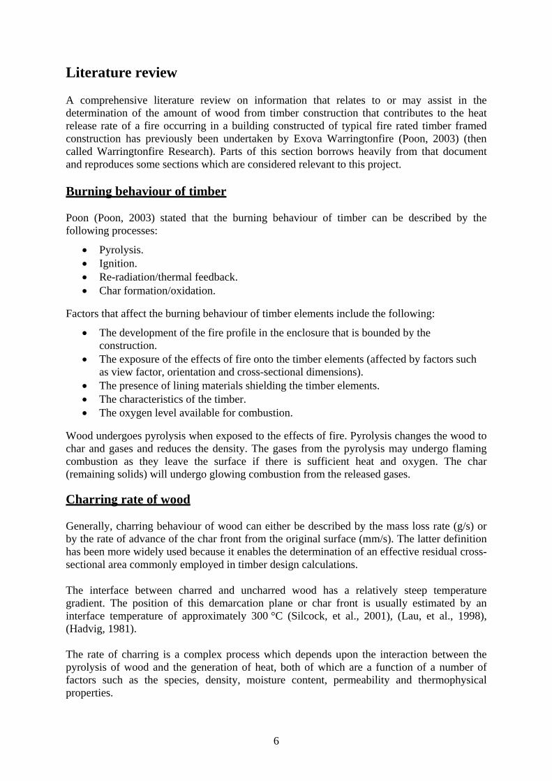
Table 3- Linings for ceiling wall to achieve various FRLs (19)
FRL Lining 30/30/30 1 x 13 mm Fire Grade Plasterboard 60/60/60 2 x 13 mm Fire Grade Plasterboard
90/90/90 or 60 minute resistance to the incipient spread of fire
2 x 16 mm Fire Grade Plasterboard
Collier and Buchanan (Colier, et al., 2002) conducted three fire resistance tests on timber stud walls. The walls were lined with fibreglass reinforced fire-rated plasterboards and the cavity was not filled with insulation. The times to onset of char formation are given in Table 4.
Table 4 - Time to onset of char in timber stud walls
FRL achieved (mins)
Lining thickness (each side)
Load (kN per stud)
Onset of char (mins)
30 9.5 mm 8 15 60 12.7 mm 2 25 60 16.2 mm 3 33
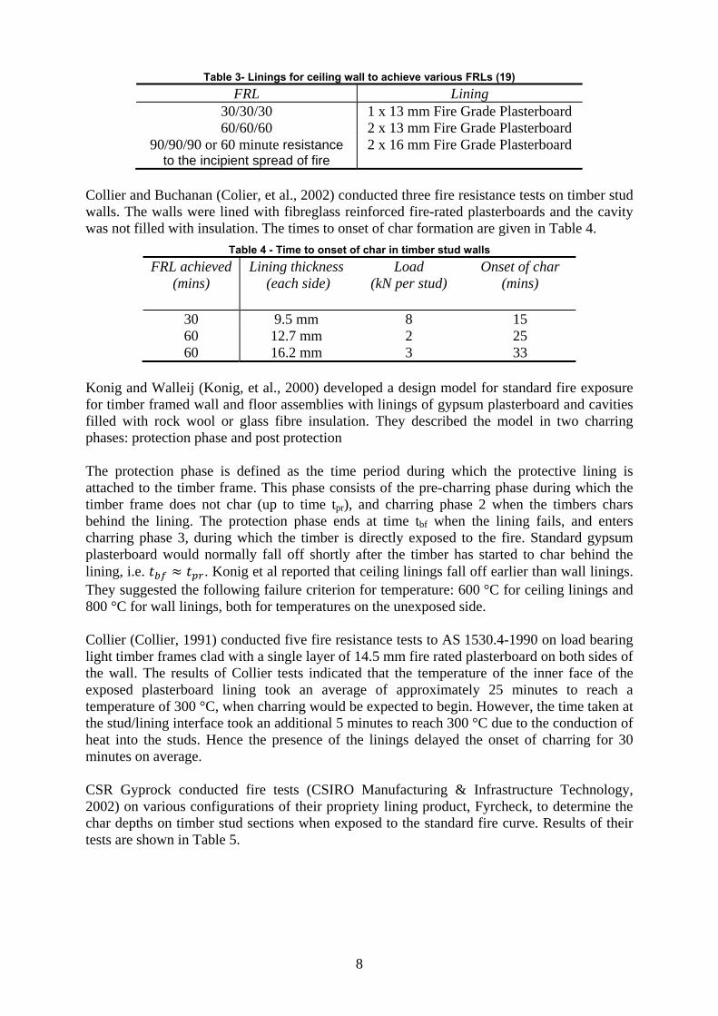
Konig and Walleij (Konig, et al., 2000) developed a design model for standard fire exposure for timber framed wall and floor assemblies with linings of gypsum plasterboard and cavities filled with rock wool or glass fibre insulation. They described the model in two charring phases: protection phase and post protection The protection phase is defined as the time period during which the protective lining is attached to the timber frame. This phase consists of the pre-charring phase during which the timber frame does not char (up to time tpr), and charring phase 2 when the timbers chars behind the lining. The protection phase ends at time tbf when the lining fails, and enters charring phase 3, during which the timber is directly exposed to the fire. Standard gypsum plasterboard would normally fall off shortly after the timber has started to char behind the lining, i.e. . Konig et al reported that ceiling linings fall off earlier than wall linings. They suggested the following failure criterion for temperature: 600 °C for ceiling linings and 800 °C for wall linings, both for temperatures on the unexposed side. Collier (Collier, 1991) conducted five fire resistance tests to AS 1530.4-1990 on load bearing light timber frames clad with a single layer of 14.5 mm fire rated plasterboard on both sides of the wall. The results of Collier tests indicated that the temperature of the inner face of the exposed plasterboard lining took an average of approximately 25 minutes to reach a temperature of 300 °C, when charring would be expected to begin. However, the time taken at the stud/lining interface took an additional 5 minutes to reach 300 °C due to the conduction of heat into the studs. Hence the presence of the linings delayed the onset of charring for 30 minutes on average. CSR Gyprock conducted fire tests (CSIRO Manufacturing & Infrastructure Technology, 2002) on various configurations of their propriety lining product, Fyrcheck, to determine the char depths on timber stud sections when exposed to the standard fire curve. Results of their tests are shown in Table 5.
9
Table 5 - Char depths for various Fyrchek configurations
Fyrchek sheeting configuration
Time (mins)*
Char depth (mm)
1 x 13 mm 30 0 1 x 16 mm 60 7 2 x 13 mm 90 5 2 x 16 mm 120 8
Note: * Duration of standard fire exposure to AS 1530.4-1997
This indicates that for a 60 minute FRL specification, the depth of char for timbers protected by Fyrchek is up to 7 mm after 60 minutes of exposure, and for a 90 minute FRL specification the depth of char is lower at 5 mm after 90 minutes of exposure.
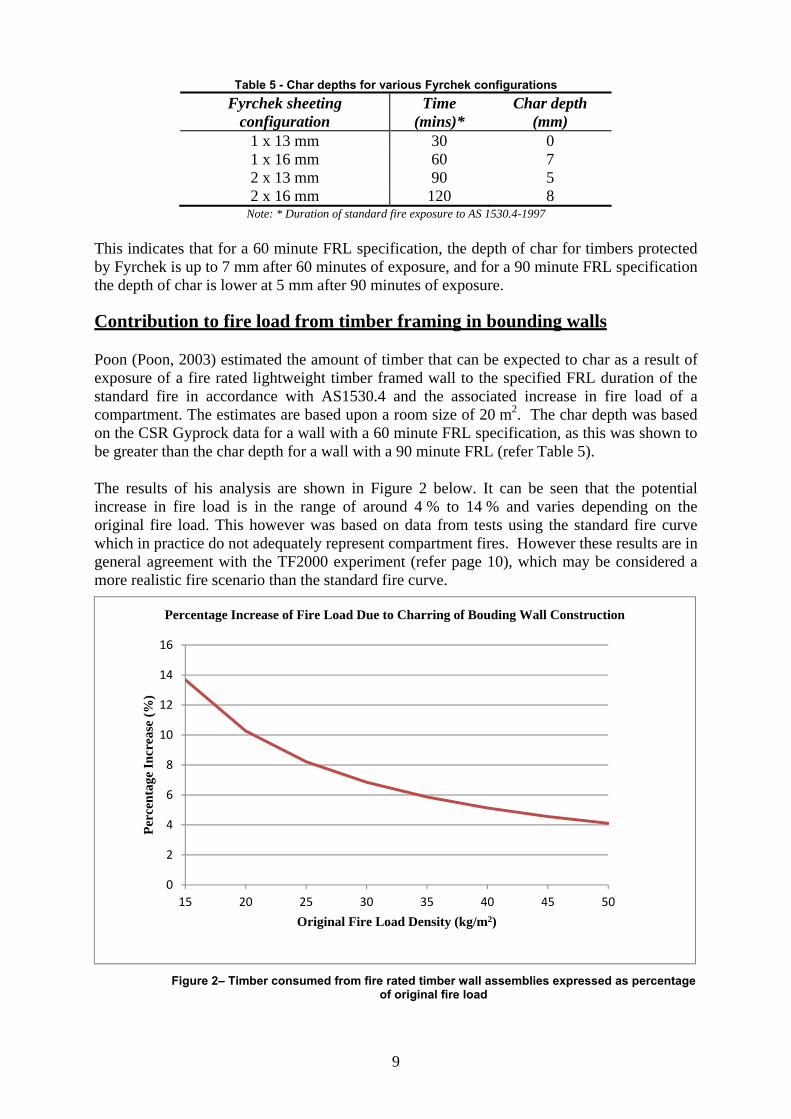
Contribution to fire load from timber framing in bounding walls
Poon (Poon, 2003) estimated the amount of timber that can be expected to char as a result of exposure of a fire rated lightweight timber framed wall to the specified FRL duration of the standard fire in accordance with AS1530.4 and the associated increase in fire load of a compartment. The estimates are based upon a room size of 20 m2. The char depth was based on the CSR Gyprock data for a wall with a 60 minute FRL specification, as this was shown to be greater than the char depth for a wall with a 90 minute FRL (refer Table 5).
The results of his analysis are shown in Figure 2 below. It can be seen that the potential increase in fire load is in the range of around 4 % to 14 % and varies depending on the original fire load. This however was based on data from tests using the standard fire curve which in practice do not adequately represent compartment fires. However these results are in general agreement with the TF2000 experiment (refer page 10), which may be considered a more realistic fire scenario than the standard fire curve.
Figure 2– Timber consumed from fire rated timber wall assemblies expressed as percentage
of original fire load
0
2
4
6
8
10
12
14
16
15 20 25 30 35 40 45 50
Per
cen
tage
In
crea
se (
%)
Original Fire Load Density (kg/m2)
Percentage Increase of Fire Load Due to Charring of Bouding Wall Construction
10
Internal walls not required to have an FRL, floor and ceiling systems and roof systems are not required by the NCC Volume One to be non-combustible in Class 2 or Class 3 buildings and may therefore use timber studs, timber joists, timber flooring and combustible insulation. The above calculation does not explicitly consider the potential fire load from these building elements however it can be considered that these may contribute to the original fire load density.
Fire load comparison
One factor which may affect the extent of the fire rated timber assembly becoming involved in the fire is the fire load. The Fire Code Reform Centre (FCRC) produced a report that contained recommended values of fire loads for use when analysing different building classes (Fire Code Research Reform Program, 1999). This document contains details about fire loads from a wide range of sources. The FCRC document states that the fire load data was reviewed by a panel of experts and then recommendations for fire loads to be used for each building Class were made. An extract of these recommended values is shown in Table 6.
Table 6 – FCRC fire load by building Class
Class Average Fireload (MJ/m2) Standard deviation
Coefficient of variation
2 1000 300 0.3
3 500 150 0.3
It can be seen that fire loads in Class 3 buildings is half that of Class 2 buildings. A full list of sources and data can be found in Appendix C of the FCRC report. A review of other sources confirmed that Class 3 buildings can generally be considered to have half the fire load density of Class 2 buildings (CIB, 1986), (England, et al., 2000), (Chitty, et al., 2003) and (Hansell, et al., 1984). It can be concluded that the risk to timber framed Class 3 buildings is less than timber framed Class 2 buildings, as the fire severity of the fully developed fire is likely to be less and the protective plasterboard lining will therefore provide a greater level of protection to underlying combustible materials. That is to say that there will be less char in a Class 3 building and therefore the contribution of the framing (if it contributes at all) to the fire load and fire severity would be expected to be less, than in a Class 2 building.
Full scale fires and fire tests
This sub-section summarises the results reported from two full scale fire tests, outlines observations from an actual fire, and introduces statistics that compare fires in Class 3 buildings with lightweight timber construction against fires in Class 3 buildings with non-combustible construction.
TF2000 full scale tests
The TF2000 (Lavender, et al., 2002) test facility was a six-storey timber frame building constructed utilising the platform construction method. The internal loadbearing walls were clad with two layers of plasterboard and 9 mm OSB, Type F2 sheathing to one side, where needed for wind bracing. The internal non-load bearing walls consisted of timber studs with one layer of plasterboard to each side. The compartment walls were twin leaf with timber studs and mineral wool insulation in between. The building had an effective 60 minute rating
11
to its construction. However, it exceeded the height limit allowable under the guidance in Approved Document B (Fire Safety) of the England and Wales Building Regulations and the requirements and recommendations of the Scottish Technical Standards in force at the time. At the time of its construction, the TF2000 building was the largest building of its type in the world. It had four flats on each of six storeys. The floor plan measured 24.1 m × 12.4 m. The height to the eaves of the building from the ground was approximately 14.4 m.
The fire test compartment was a single flat (apartment) on the second floor (level 3) in the southwest corner of the building. The fire load consisted of timber cribs spread over the floor area of the flat. Despite average atmosphere temperatures in excess of 900 °C for over 30 minutes and a total fire exposure of approximately 60 minutes there was no evidence of fire spread outside of the compartment of fire origin during the test. The cavity barriers which were designed to reduce the spread of smoke and hot gasses through concealed spaces remained effective for the duration of the test. The temperature of all rooms in the flat was below the standard fire curve except for an approximately 20 minute time when it was above, and it should be noted that the fire was declining prior to the fire brigade intervention at 64 minutes. The extent of the mass loss of the constructional timbers within the living room that would define the upper bounds of any contribution to the overall fire load was reported in reference (Lavender, 2003). The total mass of structural timber consumed was calculated to be 92.6 kg. The actual imposed fire loading for the compartment fire test comprised timber cribs distributed within the flat at a density of 25 kg/m2 over an area of 21.6 m2 giving a fire load of 540 kg of timber cribs. Hence the percentage of structural timber consumed represented approximately 14.6 % of the total fire load during the fire; the structural timber resulted in an effective 17.1 % increase in fire load. However, the effect of this additional fire load on the fire severity was not investigated. It is possible that the volatiles driven off remained unburned and either condensed or were lost as smoke. The effective FRL of the building was reported as 60 minutes. To achieve an FRL of 90 minutes it would be required to increase the overall thickness of fire rated plasterboard. It can be concluded that for the same fire exposure the increased thickness of plasterboard would reduce the charring of the timber framing. Therefore a building with an FRL of 90 minutes exposed to the same fire exposure would result in a lower percentage increase in fire load from the timber framing, when compared to the TF2000 experiment.
BRI wooden 3-storey apartment building test
The Building Research Institute (BRI) of Japan conducted a full-scale fire experiment of a 12.7 m high three-storey timber framed apartment building in 1996 to study the fire development within the building and its effects on neighboring buildings (Yuji, 1997). The building frame was constructed mainly of 4"×2" timber and each floor had 2 dwelling units (56 m²) making a total of 6 units (335 m²).
The building was designed in accordance with then current Japanese Building Standard Law for wooden three-story collective housing but with a few minor variations introduced for the purpose of the study. For example, the ceiling of one unit at the third floor had approximately 45 minutes resistance performance whilst the other unit on the third floor had 30 minutes. These requirements were for three-storey wooden independent housing and collective housing respectively in accordance with the Japanese Building Standard Law.
12
The internal and external walls of five of the six units were artificially damaged to replicate post-earthquake conditions. Various window opening combinations were employed to study their effects on the fire. The fire load was 30 kg/m² for each unit. Real furniture was used in the west unit of the first floor and timber cribs were used in the other units. After 24 minutes into the fire the fuel from the furniture appeared to have been depleted. At about 41 minutes, the burning of the structural members appeared to sustain itself and at 46 minutes the fire started to rejuvenate from burning of the structural timbers. There was about 40 minutes following flashover before burning from structural members appeared to become significant. The NCC Volume One Deemed-to-Satisfy requirements specify substantially higher FRLs for bounding construction in Class 2 and Class 3 buildings than the Japanese regulations and the risk of protective linings being damaged due to earthquakes is much less in Australia.
The Sorting House
The Sorting House is a four storey fire rated timber framed extension constructed above an existing building in Manchester, UK (UK Timber Frame Association). A fire broke out in July 2005 and quickly engulfed the room. The fire brigade managed to confine the fire to one room, although reports say that flames were coming out a broken window, which suggests the fire was post-flashover. There were no fatalities caused by the fire, although some residents suffered from smoke inhalation. After the fire was extinguished an inspection by the fire brigade and insurers showed that the timber framing and insulation was well protected by the fire rated plasterboard, and no structural damage was present. Minimal charring had occurred on the timber studs which were inspected, however a full investigation of the extent of charring was not carried out and it has not been possible to obtain further details.
American and Canadian statistics
Richardson (Richardson, 2007) examined fire loss statistics for North American hotel/motels (NCC equivalent Class 3) and compared timber constructions to non-combustible constructions. A summary of the statistics in relations to hotel/motels and injuries is presented below in Table 7.
Table 7 – Injures in north American hotels and motels
Building type Injuries per 1000 fires
With sprinklers No sprinklers
Hotel/motel of heavy timber, protected wood-frame and protected ordinary construction types2
47 74
Hotels/motels of fire resistive and protected non-combustible construction types
52 71
It can be seen that the timber constructions had a similar injury rate as non-combustible construction types. It should be noted that the taller, larger and higher risk buildings are more likely to be constructed of non-combustible materials and have sprinkler installed. This may
2 Ordinary construction is defined as “Load-bearing walls are constructed of masonry products. Interior partition walls, floors and roofs are of wood–frame construction. The undersides of floor and roof decks are designed using construction assemblies assigned a minimum one-hour fire resistance rating”

13
partially explain why buildings of non-combustible construction with sprinklers have a higher injury rate. Although not shown in the table, Richardson states that the deaths per 1000 fires follows the same trends as injuries per 1000 fires.
Risk based engineering analysis commissioned by NAFI on Class 2 buildings
The current concession for Class 2 building given in NCC Volume One Specification C1.1 Clause 3.10 and Clause 4.3 for Type A and Type B buildings was the result of research commissioned by the National Association of Forest Industries (NAFI) and submitted to the Australian Building Codes Board (ABCB). It was recognized that it would be difficult to show that timber framing did not increase the risk to occupants, as a minimal increase was expected, and therefore it was necessary to include designs which incorporated timber framing with different active and passive fire protection systems in the assessments.
The research used a risk based model to calculate the expected risk to life (ERL) and fire-cost expectation (FCE) of different fire engineered designs. No attempt to assign monetary value to life was made which avoided moral and ethical dilemmas. The results were normalised so that a then current BCA3 compliant concrete Class 2 building was assigned an ERL of 1. An ERL greater than 1 represented an increase in risk and an ERL of less than 1 represented a decrease in risk compared to the then current BCA DtS solution. The FCE quantified the cost of a fire design including its capital cost, maintenance and likely fire damage. The fire safety risk assessment model used an event based approach with discrete times and probabilistic components. The physical phenomena of a fire were mathematically modeled through the use of a number of sub-systems and the results were combined to quantify the likely risk to occupants. Due to the complexity of fire, materials and human behavior it was not thought possible to predict with complete accuracy the outcomes of different fire scenarios. This resulted in the authors using conservative estimates and recognising that the method was limited and better suited to producing comparative results rather than absolute results. A more detailed description of the model can be found in (Beck, 1994) and other sources (Yung, et al., 1993). The results of the risk analysis can be seen in Figure 3. This research showed that the ERL of a timber framed building fitted with a smoke detection system was lower than a similar concrete building without a smoke detection system. The concrete design without smoke detectors was a then current BCA DtS solution.
3 The BCA is now incorporated within the NCC, refer to the introduction of this report.
14
Figure 3– Relative Expected Risk to Life
Some other conclusions of the research included:
Increasing the FRL above 60/60/60 does not significantly decrease the risk to occupants.
Active protection systems can be extremely effective (note the reduced ERL with a sprinkler system fitted, regardless of building FRL and material).
Timber framed designs with active fire safety systems may be safer and more cost effective than non-combustible alternatives.
The research was successful in changing the BCA to allow timber framed construction for apartments up to three storeys high and resulted in the current concession for Class 2 building given in BCA Specification C1.1 Clause 3.10 and Clause 4.3 for Type A and Type B buildings.
Victoria University fire risk engineering analysis relating to Class 3 timber framed buildings
In 2002 Victoria University (VU) performed a fire engineering analysis of low rise and medium rise Class 3 timber framed buildings to assess whether the concession which allows timber framing should be extended (Verghese, et al., 2002). The objective of the project was to undertake a fire engineering analysis to investigate extending the current concessions for Class 2 buildings with timber framing to include Class 3 buildings. The approach taken was to perform a comparative risk assessment using the FIRE-RISK model. The aim was to compare
1.04
1.05
1.18
2.27
1.01
1
0.8
0.81
0.9
1.75
0.78
0.77
0.56
0.67
0.67
0.75
0.66
0.66
0.4
0.4
0.41
0.45
0.4
0.4
120/120/120Timber
90/90/90Timber
60/60/60Timber
Non-FRTimber
60/60/60Concrete
90/90/90Concrete
0 0.5 1 1.5 2 2.5Relative ERL
Relative Expected Risk to Life For Different Configurations
Smoke alarms & sprinklers Sprinklers Smoke alarms No active fire protection
BuildingFRL and Material
15
the risk to life from a current DtS compliant Class 3 construction to a timber framed Class 3 construction.
Two Class 3 buildings were compared; one BCA DtS compliant non-combustible construction and one timber framed construction. Input states (window open/close, door open/close, occupant state, etc) formed 384 different building scenarios. The timber framing was modeled as increasing the initial fire load density by 25 % (primary) or 100 % (sensitivity). The report noted that the increased fire load resulted in a higher likelihood of barrier failure, but not of the barriers failing earlier. This is due to the increased fire load creating a fire of longer duration and not higher intensity. The risk to occupants was divided into two categories; those in the compartment of fire origin and those not in the compartment of fire origin. The report found that an increase in fire load results in a greater risk to occupants not in the compartment of fire origin; the risk to occupants in the compartment of fire origin does not significantly change. This is consistent with the timber framing being modeled as an increased fire load that leads to an increase in fully developed fire duration, however the timber framing does not impact on the earlier stages of the fire when the safety of occupants in the compartment of fire origin is critical. The model considered timber framed walls with fire resistance levels of 60 minutes, 90 minutes and 120 minutes. The barrier failure times closely match the FRL of the element and therefore it can be concluded that the fire model used approximates the standard fire curve. However, the results of analysis show that the timber framed wall has a longer average time to failure than the steel framed wall. As the fire load in the room is increased (from the presumed contribution of the timber studs in the bounding wall) the probability of the timber wall failing increases, however the predicted time to failure remains similar. The report makes no attempt to analyze whether, or how much, the timber framing in the bounding walls may contribute to the fire load or fire severity. The 25 % and 100 % chosen is somewhat high; it is not clear how the authors decided that timber framing in the bounding walls may present an increase in fire load of between 25 % and 100 %. It is possible a more realistic figure would have been in the range of a 5 % to 20 % increase as shown in Figure 2 and found in the TF2000 experiment. The experiments undertaken as part of this study subsequently demonstrated there was no increase in the effective fire load and fire severity (refer to the results section of this report). The report does not take into account the time at which the potential fire load of the timber framing may be realised and contribute to the room fire and it is modeled as being part of the “normal” fire load. The report highlights that if the timber framing does contribute to the fire load the duration of the fire will be extended and therefore the risk of the fire spreading is higher, although it concedes that the risk may be small and makes no attempt to model the framing as anything but an increased initial fire load. It is considered some of the assumptions of the analysis regarding the increase in fire load due to the timber studs in the bounding wall were flawed, and the Victoria University report does acknowledge this and makes the following statement in the conclusions: If it is assumed that the timber frame does not contribute to the fire load there is no effect of due to the timber frame on the risk to life of the ANFO4 occupants for any of the occupancies considered. 4 apartments not of fire origin

16
However, if it is assumed that the timber frame does contribute to the fire load, there may be considerable effect on the risk to life for ANFO occupants, depending on the degree of increase in the fire load. The report recommends that: If it determined that the fire load is not increased then the proposed concession be allowed in a similar terms to those for Class 2 buildings. For a more detailed analysis of the report see (Poon, 2002), (Victoria University, 2003) and (Poon, 2003).
Other risk analysis
Buchanan (Buchanan, 2000) reviewed the performance of light timber assemblies and heavy timber assemblies during the pre-flashover and post-flashover phases of a fire. Buchanan found that the pre-flashover stage is most critical to the life safety of occupants in the compartment of fire origin; the post-flashover stage is most critical or the building structure and the occupants not in the compartment of fire origin. This is consistent with the previous findings in the VU report.
Lattke and Lehmann (Lettke, et al., 2007) reviewed multi residential timber construction developments in Europe; however they did not address fire risk in great detail. They noticed a trend of European countries relaxing or changing their regulations to allow up to 5 storey buildings of timber construction. The paper highlights the ecological, economical and performance benefits of timber construction with several case studies.
Summary and discussion of literature review
The literature review confirmed that timber burns through a mechanism that includes pyrolysis and charring and:
Experiments using standard fire curves have shown that the char rate can be approximated as a linear function of time, for unprotected timber.
Fire Rated Plasterboard can provide approximately 25 minutes protection with a single 12.7 mm layer of plasterboard and 33 minutes with a single 16.2 mm layer of fire rated plasterboard in the standard fire test before the timber starts to char.
Real fires in compartments are significantly different than the standard fire test, as highlighted by the TF2000 experiments.
Fire rated assemblies can be expected to have different performance characteristics when exposed to a real compartment fire compared to a standard fire curve.
The literature review found previous work showing that timber framing protected by fire rated plasterboard does not increase the risk to occupants within the compartment of fire origin. This is primarily due to the protective nature of the plasterboard and the fact that any occupants within the compartment of fire origin are likely to have been incapacitated or killed by the time the timber framework begins to char, if the fire progresses to a fully developed fire and risks charring the timber. In other words, by the time the timber framing is involved in the fire the tenability limits in the compartment will have been exceeded.
17
The previous risk analysis undertaken by Victoria University showed that there may be an increase in risk to occupants not in the compartment of fire origin due to a prolonged, and possibly more severe, fully developed fire stage which may increase the likelihood of fire barriers failing. However, the risk assessment did not consider how much timber studs in the bounding walls may contribute to fire severity and at what stage of the fire the studs may contribute. The literature review established that the fully developed stage is relatively short, and that fire rated plasterboard may protect the timber studs during this time so that the timber studs are not involved in the fire until the decay phase, when the risk of barrier failure is lower and the impact on fire severity is negligible. The literature review also found that additional fire safety measures can help to reduce the risk to occupants not in the compartment of fire origin. For example sprinklers can drastically reduce the risk to occupants in Class 2 buildings, and a smoke detection system also reduces the risk. It was on that basis that the original concession for Class 2 buildings was passed. The current concession applies if a smoke detection system is fitted and has further relaxations if the building is fitted with a compliant sprinkler system. Based on the literature review and the above discussion it is considered that:
It is important to quantify any increase in fire severity the timber framed construction may produce, and at what stage of the fire it is produced. The potential fire load of timber framing and the amount of this which is consumed in a fire has been investigated based on the results from the standard fire curve and other studies. However, at what time this occurs has not come under significant scrutiny. It is considered that if the increase in fire severity is not during the fully developed stage, and is in the decay stage, the affect may be small.
Further work is required to properly quantify the affect fire rated protected timber studs in bounding walls may have on the fire severity of a fully developed compartment fire.
The remainder of this report describes experiments that address the above focusing particularly in quantifying any variations in fire severity.

18
Experiment methodology
The literature review concluded that further work was needed to quantify the affect that fire rated timber assemblies may have on the severity of a compartment fire. Timber fire rated assemblies, steel fire rated assemblies and other fire rated wall assemblies are tested to the same standards and given the appropriate FRL based on structural adequacy, integrity and insulation performance. These tests do not attempt to quantify any volatiles that may be produced when certain materials (eg timber) are exposed to fire or the associated increase in fire severity.
Two full scale experiments were designed and performed to investigate the contribution of timber studs protected by fire rated plasterboard to the severity of a compartment fire in a typical Class 3 building. The tests were undertaken by Exova Warringtonfire at Victoria University’s Fiskville facility.
General setup
Two room enclosures were constructed. One enclosure was constructed using a fire rated non-combustible steel stud and steel joist system with non-combustible insulation and is termed the “control” test. The other enclosure was constructed using a fire rated timber framed system with timber I-beam joists, of the type that is currently allowed for low rise and medium rise Class 2 buildings under the concession5 and is termed the “timber framed” test. The exception to this was that combustible insulation was used in the walls of the timber framed test which is currently not permitted under the concession.
Each fire room had the dimensions 4 m x 4 m x 2.4 m. An opening of 2 m width x 1.2 m height was located in the center of the front wall with the sill at a height of 0.5 m above the floor. A corridor at the rear of the fire room had dimensions 6 m x 1 m x 2.1 m. A fire door separated the corridor from the fire room. The timber framed test fire door and the control fire test doors were fitted with intumescent seals and were identical except that medium temperature smoke seals were additionally fitted to the timber framed test fire door. This was part of a separate study and further details are not included in this report.
Both enclosures were lined with fire rated plasterboard to achieve the same nominal FRL of 90/90/90 in general accordance with the CSR RedBook (CSR, 2004) and the WoodSolutions Timber-framed Construction for Multi-residential Buildings Class, 2, 3 and 9c Technical Manual (Forest & Wood Products Australia Limited, 2010). The FRL was achieved by lining the timber or steel studs with two layers of 13 mm fire rated plasterboard on either side of the studs for the walls and two layers of 16 mm on the underside of the ceiling joists. Particle board flooring was placed above the I-beam floor joists. The control test had non-combustible glass wool insulation installed in the cavities and the timber framed test had polyester insulation. The polyester insulation is currently not permitted by the NCC Volume One under the concession for Class 2 buildings or for general loadbearing walls irrespective of whether or not the framing is of timber or steel.
An external façade of nominal height 6 m and a side façade of the same height were present on the external face of the fire room, extending above the fire room opening. The facades 5 The concession is given in NCC Volume One Specification C1.1 Clause 3.10 and Clause 4.3 for Type A construction and
Type B construction, respectively.
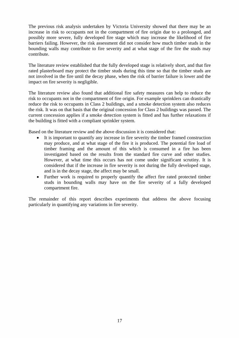
were simtest. Ththe enclfrom the
The firewhich efigures Fire Loconservthe likefire loadCouncil(CIB WDeemedloadbeaA and T
The firepine whair/woodistribucolumnmore udistribu
The cribof woodminutes
milar excephis was outslosure. The e rest of thi
e load of thequates to aof the liter
oad Compavative becaulihood that d gives an l for Resea
W14) calculd-to-Satisfyaring construType B cons
e load consihich was pd ratio in th
uted so that . The cribs
uniform gasution of the c
bs were ignd wool undes of the first
pt that a horside the testfaçade forms report. A
Figu
he compartmapproximateature review
arison sectiuse as the fithe buildinestimated e
arch & Innolation meth
y provisionuction bounstruction. Th
isted of 16 pre-conditiohe crib was
they are nwere not p
s temperatucribs and Fi
nited by plaer the cribs t crib being
rizontal projt enclosure med part of diagram of
ure 4– Diagra
ment was cely 740 MJ/w (mean ofion above)ire load inc
ng fabric woequivalent ovation in hod. This es for Clas
nding sole ohe total mas
cribs. The coned. The 1:1. The len
not in closeplaced immure to be igure 6 show
acing a nomand ignitingignited.
19
jection was it was not a different the test setu
am showing b
chosen to b/m2. This fif 500 MJ/m. It was c
creases the dould becomfire exposuBuilding &
exposure is ss 2 and occupancy uss of cribs i
cribs were cmass of eangth and wie proximity
mediately adimposed o
ws a photog
minal 100 mg with a gas
fitted to thexpected tostudy and thup is shown
burn room, co
be 41 kg/m2
ire load wam2 and standconsidered duration an
me involved ure of 61 m& Construct
consistent Class 3 b
units to achin each expe
constructedach crib width of the c
y to any of djacent to thon these elgraph of the
ml methylates torch. All
e façade foro impact on herefore then in Figure 4
orridor and fa
2 (kg wood s based on
dard deviatithat this hd / or severin the fire a
minutes usintion Workin
with the Nuildings wieve an FRLeriment was
d from 40 mwas approxicrib was 44
the walls ohe walls or lements. Fifire room w
ed spirits onthe cribs w
r the timbern the fire seve façade is e4 below.
acade
d per m2 flothe 95th p
ion of 150 high fire lority of fire also increasng the Interng CommisNCC Volu
which requiL of -/60/60s 656 kg.
mm x 40 mmimately 41 cm. The cror the centcolumn to
igure 5 shwith cribs in
nto a small were ignited
r framed verity in excluded
oor area) ercentile (refer to oad was and thus ses. This rnational ssion 14
ume One ire non-
0 in Type
m radiata kg. The
ribs were tral steel
allow a ows the n place.
quantity within 2

A protewas clatemperaof compwere als
Instru
This subThe pucompartcompare
ected steel 2ad with oneature rise ofparing the so taken and
Figure 5–
Figure
umentatio
b-section ouurpose of thtment fires e the fire s
200UC59 coe layer of 2f the steel cofire severityd these are d
– Distribution
e 6– Photo of
n
utlines the ihe experimand the in
severity incl
olumn was 25 mm thicolumn was my of the twdescribed b
of cribs in fi
cribs in fire r
instrumentament was to
strumentatiluded: gas
20
located in ck ceramic measured a
wo compartmbelow.
re room. Stee
room. Steel c
ation of the o investigation was destemperature
the center owool of no
and this wasment fires;
el column sh
column visibl
experimentte the diffesigned accoe in fire ro
of the roomominal 96 k consideredhowever o
own in cente
e in center of
t that is releerence in fordingly. Thom; perform
m. The steelkg/m3 dens
d the primarother measu
er of room.
f room.
evant to thisfire severityhe methodsmance of f
l column sity. The ry means urements
s project. y of the used to
fire rated

wall ancolumn
A nomimeasureand 1.8
The easthe unexthe unexthe cavilocated
The ceiplasterb
The proaccordaat each
A timbthermocwere lo1.2 m.
Pressurefire room
nd ceiling win the nom
nally evenlye the gas temm. The arra
stern wall oxposed facexposed surfity of the wat the cente
ling was inboard. These
otected steelance with Asection, as s
Figure are o
ber noggin couple was ocated at de
e differentim) and poin
with respecinal centre
y spaced armperature. ay was plac
of the room e of the expface of the u
wall, in the ier and at the
nstrumentede were locat
l column wS 1530.4 atshown in Fi
Fig
8 – Photograout of shot, ho
in the ealocated at th
epths of 3 m
al was meants towards
ct to insulaof the room
rray (3 x 3 xThe heightsed so as not
was instrumposed plasteunexposed nsulation, t
e quarter po
d with five sted at the ce
which was lot two transvigure 7, loca
gure 7 – Nom
aph of steel cowever therm
astern wall he interface
mm, 6 mm,
asured betwthe north-e
21
ation; and,m. These are
x 3) of therms of the thert to be imm
mented. Fiverboard. Fivplasterboar
to measure gints.
surface therenter and qu
ocated in thverse sectionated at 1 m
minal steel col
column taken mocouple lead
of the time of the stud9 mm and
ween atmospeast corner o
temperature described i
mocouples wrmocouples
mediately adj
ve surface thve surface thrd and five tgas tempera
rmocouplesuarter points
he center of ns. There weand 2 m he
lumn thermo
while columds can be see
mber framed and the FR
12 mm in
pheric presof the room
e profile oin more deta
was located in the treesjacent to a c
hermocouplhermocouplthermocoupature. The th
s on the unes.
the room were four sur
eights.
couple locati
n was being en at the left
ed test waR plasterboathe timber
sure (at a lm at heights o
of a protectail below.
d in the fire s were 0.6 mcrib.
les were loles were lo
ples were lothermocoup
exposed fac
was instrumrface thermo
ions
clad. Thermoend of the co
as instrumeard. Thermostud at a h
location outof 0.3 m an
ted steel
room to m, 1.2 m
cated on cated on
ocated in ples were
ce of the
mented in ocouples
ocouples olumn.
ented. A ocouples height of
tside the nd 2.1 m.

22
The pressure tapping were orientated to minimize the affect of vertical fire induced flow by aligning them so that the openings were not in line with this flow.
One video camera recorded from a position in front of the window opening, at a suitable distance. Witnesses took photos as appropriate. Witnesses took written observations of key events.
Summary of experiment equipment and methodology
The experiment was designed to compare the fire severity of a compartment fire where the bounding construction was non-combustible and a compartment fire where the bounding construction was fire rated lightweight timber construction. The primary measurements taken to quantify the fire severity were the gas temperature in fire room, performance of fire rated wall with respect to insulation, and the temperature profile of a protected steel column in the nominal center of the room. The instrumentation was designed to collect data in these areas.
The rooms were constructed according to the manufacturer’s instructions. The fire load chosen was at the high end of what could be expected in Australian Class 3 buildings in order to produce conservative results.

23
Results
This section highlights the key results of the experiments.
Both tests were terminated prior to the fire completely extinguishing. When it was deemed necessary to terminate the test, water was applied via a hose and the instrumentation was disconnected. The control test was terminated after 66 minutes due to flaming of the flooring above the ceiling being observed (i.e. failure of the floor system). The timber framed test was terminated after 114 minutes due to flaming of the ceiling insulation and the formation of burning droplets being observed. At this point there was a risk of the flooring above igniting and the fire was extinguished. Therefore there was a longer duration of data gathered in the timber framed test compared to the control test.
Comparison of enclosure temperatures
The average temperature measurements of all the fire room gas temperature thermocouples are presented below in Figure 9. The temperature prescribed by AS1530.4 for the standard fire curve is also displayed on the graph along with a delayed standard fire curve which better correlated with the growth phase of the compartment fire.
Figure 9 – Time versus temperature for the control test, the timber framed test and the
standard fire curve (AS1530.4)
It can be seen that the average compartment temperature for both tests follow the same general growth, fully developed, and decay pattern. The temperature time profiles in both tests are comparable with no evidence of increased fire severity due to the timber framed construction.
0
200
400
600
800
1000
1200
0 10 20 30 40 50 60
Ave
rage
Tem
per
atu
re (
C)
Time (minutes)
Fire Room Average Gas Temperature (average of all fire room gas temperature thermocouples)
Control Test AS1530.4 "Standard fire curve"
Timber Framed Test Delayed AS1530.4 "Standard fire curve"
24
The results also display the differences between a compartment fire and the standard fire curve, the compartment fire temperature was above (more severe) than that of the delayed standard fire curve for approximately 30-35 minutes, however after this time the standard fire curve was more severe.
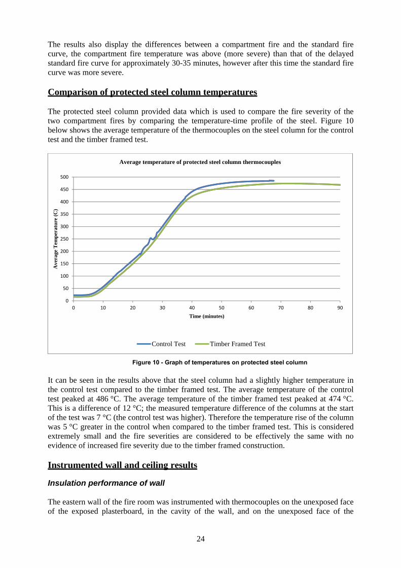
Comparison of protected steel column temperatures
The protected steel column provided data which is used to compare the fire severity of the two compartment fires by comparing the temperature-time profile of the steel. Figure 10 below shows the average temperature of the thermocouples on the steel column for the control test and the timber framed test.
Figure 10 - Graph of temperatures on protected steel column
It can be seen in the results above that the steel column had a slightly higher temperature in the control test compared to the timber framed test. The average temperature of the control test peaked at 486 °C. The average temperature of the timber framed test peaked at 474 °C. This is a difference of 12 °C; the measured temperature difference of the columns at the start of the test was 7 °C (the control test was higher). Therefore the temperature rise of the column was 5 °C greater in the control when compared to the timber framed test. This is considered extremely small and the fire severities are considered to be effectively the same with no evidence of increased fire severity due to the timber framed construction.
Instrumented wall and ceiling results
Insulation performance of wall
The eastern wall of the fire room was instrumented with thermocouples on the unexposed face of the exposed plasterboard, in the cavity of the wall, and on the unexposed face of the
0
50
100
150
200
250
300
350
400
450
500
0 10 20 30 40 50 60 70 80 90
Ave
rage
Tem
per
atu
re (
C)
Time (minutes)
Average temperature of protected steel column thermocouples
Control Test Timber Framed Test

25
unexposed plasterboard. The thermocouple readings on the unexposed face of the unexposed side of the wall are shown below in Figure 11.
Figure 11 – Unexposed face of the unexposed side of the wall
It can be seen from the temperature profile above that the temperature on the unexposed face of the wall was similar for both tests, and no inference regarding fire severity can be made based on the data. However, it should be noted that neither wall showed an average rise in temperature greater than 140 °C and no individual thermocouple rise was greater than 180 °C, and the wall can therefore be considered to have maintained its fire separation function with respect to insulation, based on the insulation failure criteria in AS1530.4.
Cavity temperatures
The thermocouple readings within the cavity of the wall are shown in Figure 12. The temperatures within the cavity are similar until approximately 40 minutes into the test. At this point the measured temperature within the cavity of the control test rises quicker than that of the timber framed test. The measured temperature in the timber framed test starts to rise at approximately 45 minutes and reaches a transient peak at 48 minutes. This transient peak is expected to be a consequence of the polyester insulation softening. It can be concluded that from approximately 48 minutes onwards the thermocouples in the timber framed test were exposed to air and the thermocouples in the control test were still embedded within the glass wool insulation. Additionally, the thermocouples in the timber framed test may have been fouled by the residue of the polyester insulation. Therefore a direct comparison of temperatures within the cavity is not considered meaningful and no conclusions can be drawn regarding the lower measured cavity temperatures within the timber framed test except to note that there was no evidence of increased fire severity due to the timber framed construction for the first 40 minutes.
0
10
20
30
40
50
60
70
0 10 20 30 40 50 60 70 80 90
Ave
rage
Tem
per
atu
re (
C)
Time (minutes)
Average temperatre of unexposed face of the unexposed side of the wall
Control Test Timber Framed Test

26
Figure 12 – Average temperature in middle of the cavity of the wall
Ceiling temperatures
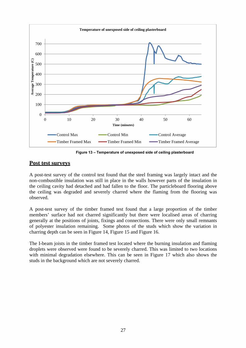
Thermocouples were located on the unexposed face of the ceiling plasterboard. The average temperature, maximum temperature and minimum temperature measurements are given in Figure 13 below. It can be seen that the temperature are reasonably consistent from ignition until approximately 35 minutes into the test for both of the tests. At approximately 35 minutes time the temperatures diverge with the temperatures in the control test rising quicker than the temperatures in the timber framed test, however the minimum temperature measurements are similar. It is expected that the high temperatures in the control test are due to localised deterioration of the ceiling systems. The reasons for this localised deterioration cannot be clearly identified but may include a localised fixing failure or localised board failure.
Flaming from the flooring above the ceiling was observed after 66 minutes in the control test and the control test was terminated at this point. Flaming polyester droplets from the ceiling were observed in the timber framed test at approximately 114 minutes and the test was terminated at this point. Ignition of the timber floor was expected to have occurred at this time.
0
50
100
150
200
250
300
350
400
0 10 20 30 40 50 60 70 80 90
Ave
rage
Tem
per
atu
re (
C)
Time (minutes)
Average temperatre at mididle of cavity of the wall
Control Test Timber Framed Test
27
Figure 13 – Temperature of unexposed side of ceiling plasterboard
Post test surveys A post-test survey of the control test found that the steel framing was largely intact and the non-combustible insulation was still in place in the walls however parts of the insulation in the ceiling cavity had detached and had fallen to the floor. The particleboard flooring above the ceiling was degraded and severely charred where the flaming from the flooring was observed.
A post-test survey of the timber framed test found that a large proportion of the timber members’ surface had not charred significantly but there were localised areas of charring generally at the positions of joints, fixings and connections. There were only small remnants of polyester insulation remaining. Some photos of the studs which show the variation in charring depth can be seen in Figure 14, Figure 15 and Figure 16.
The I-beam joists in the timber framed test located where the burning insulation and flaming droplets were observed were found to be severely charred. This was limited to two locations with minimal degradation elsewhere. This can be seen in Figure 17 which also shows the studs in the background which are not severely charred.
0
100
200
300
400
500
600
700
0 10 20 30 40 50 60
Ave
rage
Tem
per
atu
re (
C)
Time (minutes)
Temperature of unexposed side of ceiling plasterboard
Control Max Control Min Control Average
Timber Framed Max Timber Framed Min Timber Framed Average
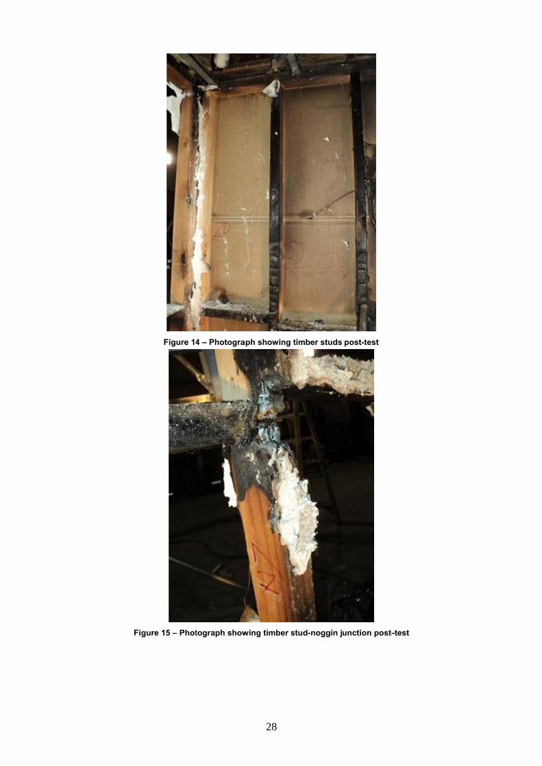
Figu
Figure 14
ure 15 – Phot
4 – Photogra
tograph show
28
aph showing t
wing timber s
timber studs
stud-noggin j
post-test
unction post--test
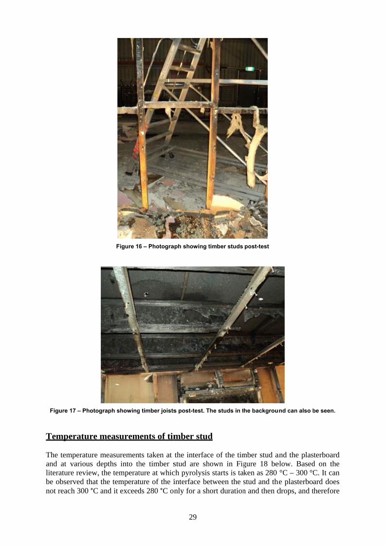
Figure
Tempe
The temand at literaturbe obsenot reac
17 – Photogr
erature m
mperature mvarious dep
re review, therved that thch 300 °C an
Figure 16
raph showing
measurem
measuremenpths into thhe temperathe temperatnd it exceed
6 – Photogra
g timber joists
ments of tim
ts taken at he timber sture at whicture of the ids 280 °C on
29
aph showing t
s post-test. T
mber stud
the interfacstud are shch pyrolysisinterface benly for a sh
timber studs
The studs in t
d
ce of the timhown in Figs starts is taetween the short duration
post-test
he backgrou
mber stud agure 18 beken as 280 stud and thn and then d
nd can also b
and the plaselow. Based°C – 300 °C
he plasterbodrops, and t
be seen.
sterboard d on the C. It can ard does therefore
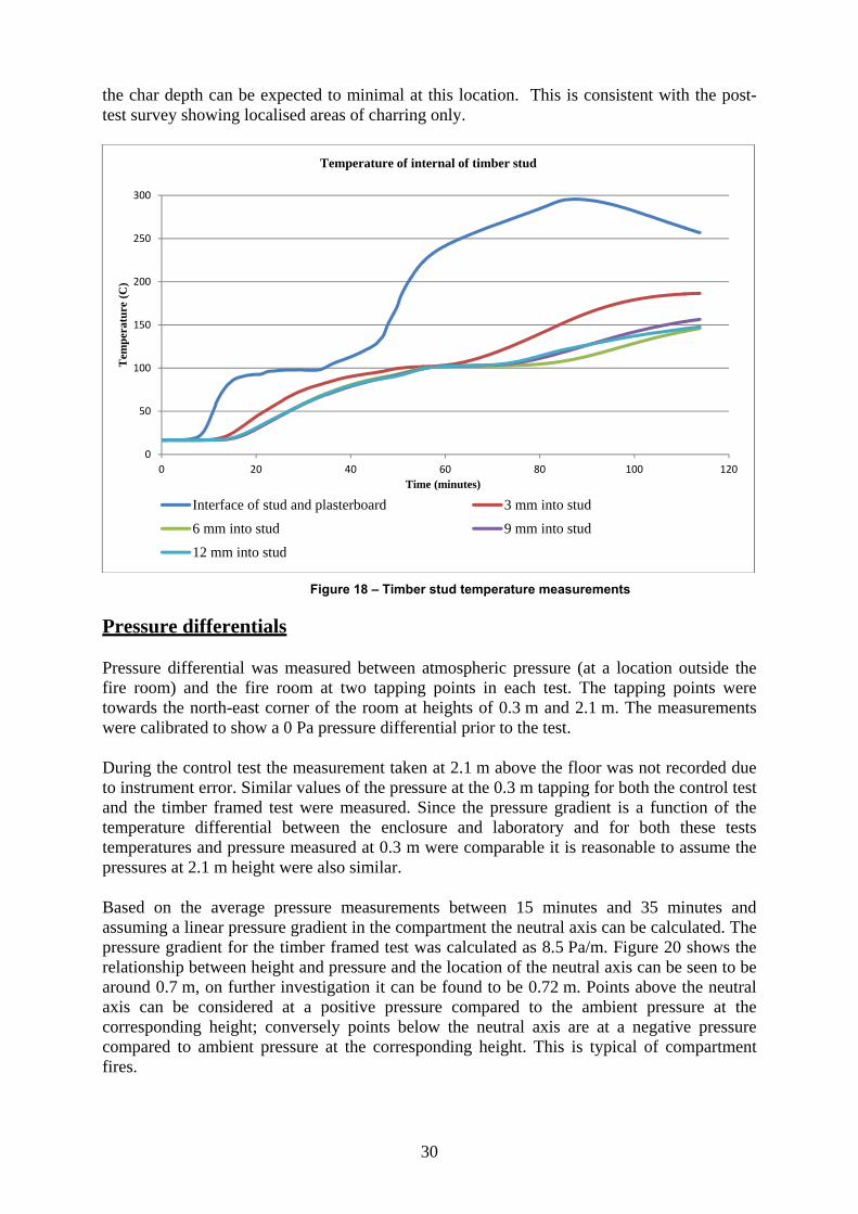
30
the char depth can be expected to minimal at this location. This is consistent with the post-test survey showing localised areas of charring only.
Figure 18 – Timber stud temperature measurements
Pressure differentials
Pressure differential was measured between atmospheric pressure (at a location outside the fire room) and the fire room at two tapping points in each test. The tapping points were towards the north-east corner of the room at heights of 0.3 m and 2.1 m. The measurements were calibrated to show a 0 Pa pressure differential prior to the test.
During the control test the measurement taken at 2.1 m above the floor was not recorded due to instrument error. Similar values of the pressure at the 0.3 m tapping for both the control test and the timber framed test were measured. Since the pressure gradient is a function of the temperature differential between the enclosure and laboratory and for both these tests temperatures and pressure measured at 0.3 m were comparable it is reasonable to assume the pressures at 2.1 m height were also similar.
Based on the average pressure measurements between 15 minutes and 35 minutes and assuming a linear pressure gradient in the compartment the neutral axis can be calculated. The pressure gradient for the timber framed test was calculated as 8.5 Pa/m. Figure 20 shows the relationship between height and pressure and the location of the neutral axis can be seen to be around 0.7 m, on further investigation it can be found to be 0.72 m. Points above the neutral axis can be considered at a positive pressure compared to the ambient pressure at the corresponding height; conversely points below the neutral axis are at a negative pressure compared to ambient pressure at the corresponding height. This is typical of compartment fires.
0
50
100
150
200
250
300
0 20 40 60 80 100 120
Tem
per
atu
re (
C)
Time (minutes)
Temperature of internal of timber stud
Interface of stud and plasterboard 3 mm into stud
6 mm into stud 9 mm into stud
12 mm into stud
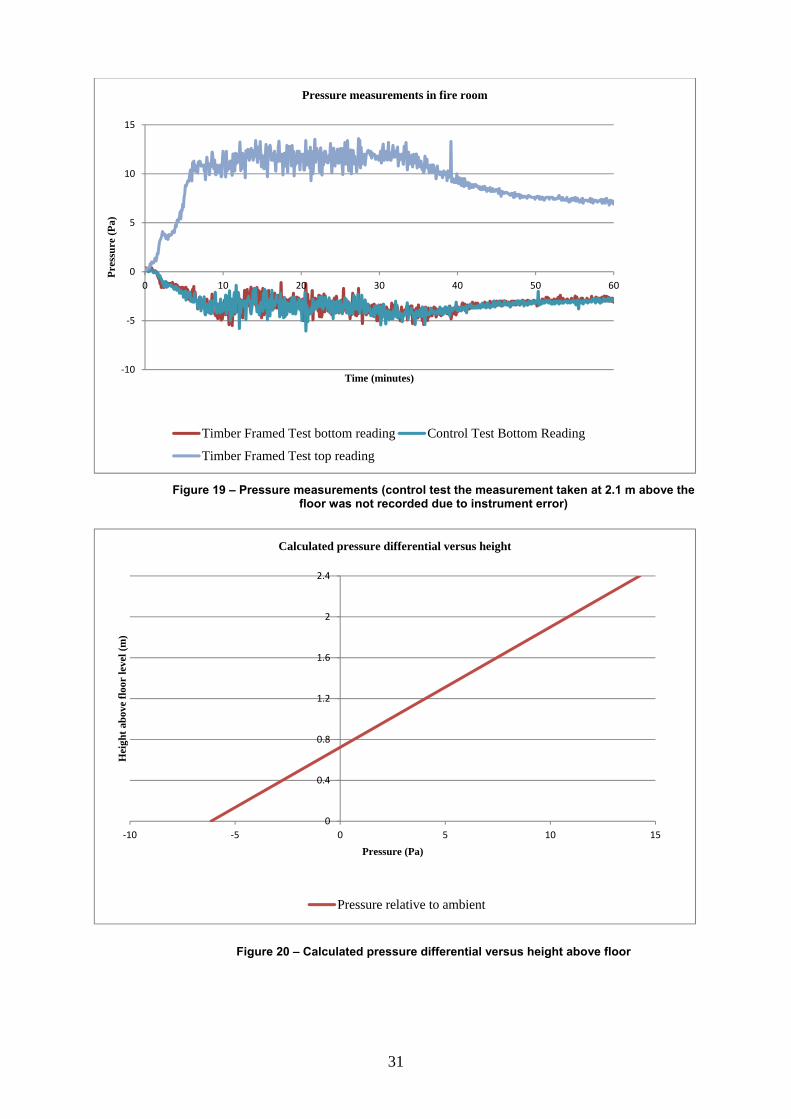
31
Figure 19 – Pressure measurements (control test the measurement taken at 2.1 m above the
floor was not recorded due to instrument error)
Figure 20 – Calculated pressure differential versus height above floor
‐10
‐5
0
5
10
15
0 10 20 30 40 50 60
Pre
ssu
re (
Pa)
Time (minutes)
Pressure measurements in fire room
Timber Framed Test bottom reading Control Test Bottom Reading
Timber Framed Test top reading
0
0.4
0.8
1.2
1.6
2
2.4
‐10 ‐5 0 5 10 15
Hei
ght
abov
e fl
oor
leve
l (m
)
Pressure (Pa)
Calculated pressure differential versus height
Pressure relative to ambient

Visual
Visual otests waplasterbthe open
Flaming66 minuobservepolyeste Photos approxifloor lev
C
l observat
observationas there flamboard liningning which
g on the flooutes. Flamined; howeverer from the
of the tesmate. An exvel was add
Control test
2 m
10 m
tions
ns of the tesming througgs was not were expos
oring aboveng on the fr flaming ofceiling was
st taken atxternal hori
ditionally fit
Ti
minutes into
minutes into th
st were recogh the wallsobserved, wsed to the ex
e the fire roflooring abof the polyess observed a
t various tizontal projtted to the ti
imber frame
test
he test
32
orded by wis observed.with the excxternal flam
om was obsove the firester insulatiat 114 minu
times into ection of 0.imber frame
ed test
itnesses. AtSignificant
ception of tme.
served in the room in thion in the c
utes.
the test a.6 m depth ed test as pa
Control
5
15
t no points dt degradatiothe plasterb
he control tehe timber fceiling and
are shown and at a heiart of a sepa
test T
minutes into
5 minutes into
during eitheon of the unboard lining
est at approxframed test flaming dro
below. Timight of 2.2 marate study.
Timber fram
o the test
to the test
er of the nexposed gs above
ximately was not
oplets of
mes are m above
med test

20 m
30 m
40 m
50 m
minutes into th
minutes into th
minutes into th
minutes into th
he test
he test
he test
he test
33
25
35
45
55
5 minutes into
5 minutes into
5 minutes into
5 minutes into
to the test
to the test
to the test
to the test
34
Discussion and conclusions
This project investigated a proposed extension of the concession in the NCC Volume One Deemed-to-Satisfy provisions which allows the use of fire rated lightweight timber construction in Class 2 buildings of Type A and Type B construction to also include Class 3 buildings.
A previous risk assessment (Verghese, et al., 2002) undertaken by Victoria University raised the issue that combustible materials may increase the effective fire load and hence severity of a fire and therefore recommended that:
“If it determined that the (effective) fire load is not increased then the proposed concession be allowed in similar terms to those for Class 2 buildings”
The risk assessment made no attempt to model or quantify the increase in fire severity due to the timber studs in the bounding wall and did not consider the protection of timber studs and framing by plasterboard or other fire protective linings but simply concluded that if the fire load in the room of fire origin is increased then there is an increased risk of fire spread.
The protective nature of fire rated plasterboard is highlighted in the literature review in the body of this report.
Based on the literature review and considering the recommendations from the Victoria University risk assessment, an experiment was developed which was designed to compare the severity of fires within a compartment constructed using a non-combustible fire rated steel framed system with non-combustible cavity insulation and an otherwise similar compartment constructed using fire rated timber construction with combustible insulation.
The experiment results showed that the severity of fires within the two compartments was comparable and that the timber studs in the bounding walls, timber joists and combustible insulation did not increase the fire severity. This conclusion was based on a number of key measurements, including gas temperatures in the compartment, non-fire side temperatures of the fire rated bounding walls and temperature rise of a protected steel column in the center of the room. None of these parameters indicated that the fire in the compartment constructed with timber studs, timber joists and combustible insulation was more severe than the fire in the compartment constructed with steel framing and non-combustible insulation.
It should also be noted that a number of fire load surveys have shown that the fire load tends to be less for Class 3 buildings compared to Class 2 buildings. The literature review found that the fire load in Class 3 buildings was generally half the fire load in Class 2 building which provides further comfort in extending the dispensation to apply to Class 3 buildings.
Based on the literature review if volatiles from timber framing contribute to the fire load the maximum increase in fire load was estimated to be in the region of 4 % to 20 %. If the high level of a 20 % increase in fire load is assumed the fire load for a Class 2 timber framed building would be expected to be approximately 60 % that of a Class 2 building of non-combustible construction.
The experimental study also showed that if the timber framed walls are lined with two layers of 13 mm thick fire grade plasterboard and ceilings with two layers of 16 mm thick fire grade plasterboard combustible insulation can also be included without increasing the fire severity.

35
Therefore it is concluded that the concession in the NCC Volume One Deemed-to-Satisfy provisions which allows the use of fire rated lightweight timber construction in Class 2 buildings could be extended to include Class 3 buildings without an increase in risk to life.
Consideration should also be given to permitting combustible cavity insulation in timber-framed walls required to have an FRL in Type A buildings.

36
Recommendations Based on the literature review, experiment results and discussion presented in this report it is recommended that the NCC Volume One be amended to extend the concession which allows timber framed construction in Class 2 buildings to include Class 3 Buildings. Furthermore, it is recommended that the requirements for non-combustible insulation be relaxed when in timber framed walls. However, due to the lack of test data relating to combustible insulation it is recommended that this relaxation apply only to timber framed walls faced with two layers of 13mm thick fire grade plasterboard These recommendations can be implemented by amending the Specification C1.1 Clause 3.10 and Clause 4.3 of NCC Volume One to read as follows (changes are shown in bold):
NCC Volume One Specification C1.1 Clause 3.10. Class 2 and Class 3 buildings: Concession
(a) A Class 2 or Class 3 building having a rise in storeys of not more than 3 need not comply with Clauses 3.1(b), (d) and (e) of Specification C1.1 and the requirement of C2.6 for non-combustible material, if it is constructed using— (i) timber framing throughout; or (ii) non-combustible material throughout; or (iii) a combination of (i) and (ii), provided— (iv) * * * * * (v) any insulation installed in the cavity of a wall required to have an FRL is non-
combustible except in a wall which is constructed using timber framing; and (vi) the building is fitted with an automatic smoke alarm system complying with
Specification E2.2a; and (b) A Class 2 or Class 3 building having a rise in storeys of not more than 4 may have
the top three storeys constructed in accordance with (a) provided— (i) the lowest storey is used solely for the purpose of parking motor vehicles or for
some other ancillary purpose; and (ii) the lowest storey is constructed of concrete or masonry including the floor between
it and the Class 2 part of the building above; and (iii) the lowest storey and the storey above are separated by construction having an
FRL of not less than 90/90/90 with no openings or penetrations that would reduce the fire-resisting performance of that construction except that a doorway in that construction may be protected by a –/60/30 self-closing fire door.
(c) In a Class 2 or Class 3 building complying with (a) or (b) and fitted with a sprinkler system complying with Specification E1.5, any FRL criterion prescribed in Table 3— (i) for any floor and any loadbearing wall, may be reduced to 60, except any FRL
criterion of 90 for an external wall must be maintained when tested from the outside; and
(ii) for any non-loadbearing internal wall, need not apply if— (A) it is lined on each side with 13 mm standard grade plasterboard or similar non-
combustible material; and (B) it extends—
(aa) to the underside of the floor next above; or (bb) to the underside of a ceiling with a resistance to the incipient spread of fire
of 60 minutes; or (cc) to the underside of a non-combustible roof covering; and
(C) any insulation installed in the cavity of the wall is non-combustible; and

37
(D) any construction joint, space or the like between the top of the wall and the floor, ceiling or roof is smoke sealed with intumescent putty or other suitable material; and
(E) any doorway in the wall is protected by a self-closing, tight fitting, solid core door not less than 35 mm thick.
NCC Volume One Specification C1.1 Clause 4.3. Class 2 and Class 3 buildings: Concession
(a) A Class 2 or Class 3 building having a rise in storeys of not more than 2 need not comply with Clause 4.1(b), (e), (f) and (h) of Specification C1.1 if it is constructed using— (i) timber framing throughout; or (ii) non-combustible material throughout; or (iii) a combination of (i) and (ii), provided— (iv) * * * * * (v) any insulation installed in the cavity of a wall required to have an FRL is non-
combustible; and (vi) the building is fitted with an automatic smoke alarm system complying with
Specification E2.2a. (b) A Class 2 or Class 3 building having a rise in storeys of not more than 2 may have
the top storey constructed in accordance with (a) provided— (i) the lowest storey is used solely for the purpose of parking motor vehicles or for
some other ancillary purpose; and (ii) the lowest storey is constructed of concrete or masonry including the floor between
it and the Class 2 part of the building above; and (iii) the lowest storey and the storey above are separated by construction having an
FRL of not less than 90/90/90 with no openings or penetrations that would reduce the fire-resisting performance of that construction except that a doorway in that construction may be protected by a –/60/30 self-closing fire door.
(c) In a Class 2 or Class 3 building complying with (a) or (b) and fitted with a sprinkler system complying with Specification E1.5, any FRL criterion prescribed in Table 4— (i) for any loadbearing wall, may be reduced to 60, except any FRL criterion of 90 for
an external wall must be maintained when tested from the outside; and (ii) for any non-loadbearing internal wall, need not apply, if—
(A) it is lined on both sides with 13 mm standard grade plasterboard or similar non-combustible material; and
(B) it extends— (aa) to the underside of the floor next above if that floor has an FRL of at least
30/30/30 or is lined on the underside with a fire-protective covering; or (bb) to the underside of a ceiling with a resistance to the incipient spread of fire
of 60 minutes; or (cc) to the underside of a non-combustible roof covering; and
(C) any insulation installed in the cavity of the wall is non-combustible; and (D) any construction joints, spaces and the like between the top of the wall and the
floor, ceiling or roof is smoke sealed with intumescent putty or other suitable material.

38
References Beck V.R. (1994) Fire Research Lecture 1993: Performance Based Fire Safety Design - Recent Developments in Australia, Fire Safety Journal. 23: pp.133-158. Buchanan (2000) Fire performance of timber construction, Progress in Structural Engineering and Materials, 2: pp.278-289. Chitty R and Fraser Mitchell J (2003) Fire Engineering: A Reference Guide, BRE Report 459, BR459, BRE, London CIB (1986) Design Guide, Structural Fire Safety, Workshop CIB W14, Fire Safety Journal. 10(2). Colier and Buchanan (2002) Fire resistance of lightweight timber framed walls, Fire technology, 38: pp.125-145. Collier (1991) Design of load bearing light timber frame walls for fire resistance: part 1, Study Report SR 36. BRANZ. CSIRO Manufacturing & Infrastructure Technology Timber-stud Plasterboard Wall Systems (2002), Assessment number FCO 1404 CSR (2004) The Redbook Fire and Acoustic Design Guide, GYP500. England J P [et al.](2000) FIRE RESISTANT BARRIERS AND STRUCTURES, Building Control Commission, Melbourne Victoria Fire Code Research Reform Program (1999) Fire Resistance and Non-Combustibility - Evaluation of Fire Resistance Levels: Techniques, Data and Results, FCRC PR 01-02. Forest & Wood Products Australia Limited. (2010) Timber-framed Construction for Multi-residential Buildings Class 2, 3 & 9c - Design and construction guide for BCA compliant sound and fire-rated construction. National Timber Development Council, (2000) Fire and Sound Rated Wall and Floor/Ceiling Systems Summary, Information Bulletin No 5. Hadvig S. (1981) Charring of wood in building fires, Technical University of Denmark. Hansell G.O. and Morgan H.P.(1984) Fire Sizes in Hotel Bedroom - Implications for Smoke Control Design, Fire Safety Journal 8: pp.177-186. Konig J and Walleij L (2000) Timber frame assemblies exposed to standard and parametric fire, Part 2: A design model for standard fire exposure, Rapport - Institutet för Träteknisk Forskning No. 0001001 pp.1-76 pp. Lau P W, Zeeland I V and White R. (1998) Modelling the char behaviour of structural timber, Proceedings of the fire and materials '98 conference, San Antonio, TX. pp.123-135

39
Lavender R J and Bullock M. (2002) Reinstatement of fire damaged timber frame buildings, Chiltern International Fire Ltd. Lavender R J (2003) To establish the extent to which the constructional timbers within the living room of the TF2000 compartment contributed to the overall fire load of the test, Chiltern International Fire Ltd, 2003. Leceister R.H. (1983) Fire resistance of timber, part 1 - performance of timber structures in fire, Workshop on timber engineering. Melbourne, Victoria. Lettke F and Lehmann S (2007) Multi-storey residential timber construction: Current developments in Europe, Journal of Green Building. 2(1) pp.119-129. Mikkola E. (1990) Charring of Wood, Research report 689, Technical research centre of Finland. National Timber Development Council. (2001) Class 2 and 3 buildings - Design and construction manual. Poon (2002) Comments on the report entitled "Fire engineering analysis of low rise class 3 timber framed buildings", by Denny Verghese and Ian Thomas of the centre of enviromental safety and risk engineering, victoria university. Warringtonfire Research (Aust) Pty Ltd. Poon (2003) Reply to VUT's comments of 11/04/20003 Warringtonfire Research (Aust) Pty Ltd. Poon. (2003) Literature review on the contribution of fire resistant timber construction to heat release rate, Warringtonfire Research (Aust) Pty Ltd. Richardson (2007) Fire losses in selected property classifications of non-residential, commercial and residential wood buildings. Part 1: Hotels/motels and care homes for aged Fire and Materials. 31: pp.97-123. Schaffer E.L. (1967) Charring rate of selected wood - transverse to grain, Research Paper FPL-69, USDA Forest Products Laboratory, Madison, Wisconsin Silcock and Shields. (2001) Relating char depth to fire severity, Fire and Materials. 25(1):9-11. Tsantaridia L.D. and Ostman B.A.L. (1998) Charring of protected wood studs, Fire and Materials. 22(2): pp.55-60. UK Timber Frame Association fire and timber frame construction – a case study [Online]. Accessed 30/03/2011. - http://www.epolitix.com/Resources/epolitix/Forum Microsites/UK Timber Frame Association/Manchester case study.pdf. Verghese D and Thomas I. (2002) Fire Engineering Analysis of Low Rise Class 3 Timber Framed Buildings, Centre for Environmental Safety and Risk Engineering, Victoria University.

40
Victoria University (2003) Reply to comments by L Pool of Warrington Fire Research (Aus) Pty Ltd on the report entitled "Fire engineering analysis of low rise class 3 timber framed buildings" Centre for Environmental Safety and Risk Engineering, Victoria University. White R.H. (1988) Charring rates of different wood species (PHD Dissertation). University of Wisconsin, Madison, WI. Yuji Hasemi (1997) Full scale burn test of wooden three story apartment building, Fire Science and Technology. 17: pp.78-92. Yung D and Hadjisophocleous G.V. (1993) The use of the NRCC risk-cost assessment model to apply for code changes for 3-storey apartment buildings in Australia Proc. Syrup. Computer Applications in Fire Protection. Worchester, Massachusetts, pp.57-62.

41
Acknowledgements The authors wish to thank the Timber Development Association (NSW) for providing assistance and the FWPA for providing funding to undertake this work.