Expression of Interest (EOI) Document for
35
Government of Nepal Ministry of Physical Infrastructure and Transport Department of Railways Rail, Metrorail and Monorail Development Project Bishalnagar, Kathmandu. Expression of Interest (EOI) Document for Shortlisting of Consulting Services for Detailed Survey, Design and Preparation of DPR of Nijgadh-Hetauda- Bharatpur of Mechi-Mahakali Electrified Railway Procurement of Consulting Services (For National and International Consulting Services) Financing Agency: Government of Nepal Issued on: October,2018
Transcript of Expression of Interest (EOI) Document for
Government of Nepal
Ministry of Physical Infrastructure and Transport
Department of Railways Rail, Metrorail and Monorail Development Project Bishalnagar, Kathmandu.
Expression of Interest (EOI) Document
for Shortlisting of Consulting Services
for Detailed Survey, Design and Preparation of DPR of Nijgadh-Hetauda-
Bharatpur of Mechi-Mahakali Electrified Railway
Procurement of Consulting Services
(For National and International Consulting Services)
Financing Agency: Government of Nepal
Issued on: October,2018

EOI Document for DPR of Nijgadh-Hetauda-Bharatpur Sector of MMER
EOI Document for DPR of Nijgadh-Hetauda-Bharatpur Sector of MMER
Abbreviations
CV - Curriculum Vitae
DO - Development Partner
EA - Executive Agency
EOI - Expression of Interest
GON - Government of Nepal
PAN - Permanent Account Number
PPA - Public Procurement Act
PPR - Public Procurement Regulation
TOR - Terms of Reference
VAT - Value Added Tax
EOI Document for DPR of Nijgadh-Hetauda-Bharatpur Sector of MMER
Contents
A. Request for Expression of Interest ............................................................................. 5
B. Instructions for submission of Expression of Interest .................................................. 6
C. Objective of Consultancy Services or Brief TOR .............................................................. 7
D. Evaluation of Consultant’s EOI Application ..................................................................... 7
E. EOI Forms & Formats ...................................................................................................... 27
1. Letter of Application ........................................................................................................ 28
2. Applicant’s Information Form ......................................................................................... 30
3. Experience ....................................................................................................................... 31
4. Capacity ........................................................................................................................... 34
5. Key Experts (Include details of Key Experts only) ........................................................... 35

EOI Document for DPR of Nijgadh-Hetauda-Bharatpur Sector of MMER
A. Request for Expression of Interest
Government of Nepal Ministry of Physical Infrastructure and Transport
Department of Railways Rail, Metrorail and Monorail Development Project
Bishalnagar, Kathmandu Notice Publication Date: 2075/06/16(Oct 2nd, 2018)
Notice No: 01/075/76
Name of Project: Detailed Survey, Design and Preparation of DPR of Nijgadh Hetauda-Bharatpur of Mechi-Mahakali Electrified Railway 1. Government of Nepal (GoN) has allocated fund toward the cost of Detailed Survey, Design and
Preparation of DPR of Nijgadh Hetauda-Bharatpur of Mechi-Mahakali Electrified Railway and
intends to apply a portion of this fund to eligible payments under the Contract for which this
Expression of Interest is invited for International consulting service.
2. The Government of Nepal, Ministry of Physical Infrastructure and Transport, Department of
Railways, Rail, Metrorail and Monorail Development Project now invites Expression of
Interest (EOI) from eligible consulting firms (“consultant”) to provide the following consulting
services: Detailed Survey, Design and Preparation of DPR of Nijgadh Hetauda-Bharatpur of
Mechi-Mahakali Electrified Railway.
3. Interested eligible consultants may obtain further information and EOI document free of cost at
the address, Government of Nepal, Ministry of Physical Infrastructure and Transport,
Department of Railways, Rail, Metrorail and Monorail Development Project, Bishalnagar,
Kathmandu, Nepal until 12:00 hrs noon 2075/07/14(31st Oct 2018) or visit e-GP system
www.bolpatra.gov.np/egp or visit the client’s website www.dorw.gov.np
4. Consultants may associate with other consultants to enhance their qualifications. 5. Expressions of interest shall be delivered online through e-GP system www.bolpatra.gov.np/egp
or manually to the address Government of Nepal, Ministry of Physical Infrastructure and
Transport, Department of Railways, Rail, Metrorail and Monorail Development Project,
Bishalnagar, Kathmandu, Nepal until 12:00 hrs noon 2075/07/14(31st Oct 2018)
6. In case the last date of obtaining and submission of the EOI documents happens to be a holiday,
the next working day will be deemed as the due date but the time will be the same as stipulated.
7. EOI will be assessed based on Qualification, Experience, and Financial Capacity of consulting
firm and key personnel. Based on evaluation of EOI, only shortlisted firms will be invited to
submit technical and financial proposal through a request for proposal.
8. Minimum score to pass the EOI is 70% in general.
EOI Document for DPR of Nijgadh-Hetauda-Bharatpur Sector of MMER
B. Instructions for submission of Expression of Interest
1. Expression of Interest may be submitted by a sole firm or a joint venture of consulting firms.
2. Interested consultants must provide information indicating that they are qualified to perform the
services (descriptions, organization and employee and of the firm or company, description of
assignments of similar nature completed in the last 7 years and their location, experience in
similar conditions, general qualifications and the key personnel to be involved in the proposed
assignment).
3. This expression of interest is open to all eligible consulting firms.
4. The assignment has been scheduled for a period of 15 months. Expected date of commencement
of the assignment is March 2019.
5. A Consultant will be selected in accordance with the QCBS method.
6. Expression of Interest should contain following information:
(i) A covering letter addressed to the representative of the client on the official letter head of
company duly signed by authorized signatory.
(ii) Applicants shall provide the following information in the respective formats given in the EOI
document:
EOI Form: Letter of Application (Form 1)
EOI Form: Applicant’s Information (Form 2)
EOI Form: Work Experience Details (Form 3(A), 3(B) & 3(C))
EOI Form: Capacity Details (Form 4)
EOI Form: Key Experts List (form 5).
7. Applicants may submit additional information with their application but shortlisting will be based on the evaluation of information requested and included in the formats provided in the EOI document.
8. The Expression of Interest (EOI) document must be duly completed and submitted in sealed envelope and should be clearly marked as “EOI Application for Short-listing for the of Detailed Survey, Design and Preparation of DPR of Nijgadh Hetauda-Bharatpur of Mechi-Mahakali Electrified Railway”. The Envelope should also clearly indicate the name and address of the Applicant. Alternatively, applicants can submit their EOI application through e-GP system by using the forms and instructions provided by the system.
9. The completed EOI document must be submitted on or before the date and address mentioned in the “Request for Expression of Interest”. In case the submission falls on public holiday the submission can be made on the next working day. Any EOI Document received after the closing time for submission of proposals shall not be considered for evaluation.
EOI Document for DPR of Nijgadh-Hetauda-Bharatpur Sector of MMER
C. Objective of Consultancy Services or Brief TOR
TERMS OF REFERENCE Detail Survey and Design
of Electrified Railway Line for
Nijgadh-Hetauda-Bharatpur Section of Mechi-Mahakali Railway 1. BACKGROUND
1.1 GENERAL Nepal is a landlocked sovereign state located in South Asia. It is situated along the southern slopes of the Himalayan mountain range bordering People's Republic of China to the North and Republic of India in the remaining three sides. The country has a rugged terrain and topography of middle and high mountains in the north and fertile flat Terai area suitable for cultivation in the south bordering India. Nepal's transport infrastructure mainly consists of roads and civil aviation, and is dominated by the roads, which provides for the movement of approximately 90 percent of all passengers and freight within the country. Air transportation is the only means to reach remote areas not yet linked to the road network. The total Road network of Nepal is about 75000 kilometres comprising of about 13000 kilometres of Strategic Road network and the remaining Local Road network consisting of district, urban and village roads. The present day Railway transportation in Nepal was limited to one narrow gauge 29 kilometre long Jayanagar–Janakpur railway in the central terai region which is now being upgraded to broad guage line and 800 meters of the 5 kilometers broad gauge line for freight service connecting ICD Birjunj, a bordering town with India, to Raxaul of India.
In order to meet the growing passenger and freight transport demand, Government of Nepal has long felt the necessity of development of railway as an alternative land transport mode for faster and cheaper movement of freight and passenger. In this respect the Government of India has provided technical and economic cooperation to strengthen the cross border rail links between India and Nepal at five different locations namely BG rail links between New Jalpaiguri (India) to Kakardvitta (Nepal); Jogabani (India) to Biratnagar (Nepal); Nautanwa (India) to Bhairahawa (Nepal) and Nepalganj Road (India) to Nepalganj (Nepal). and conversion of existing narrow gauge line between Jayanagar and Janakpur with extension up to Bardibas in the East–West Highway. Further the GoN has completed the Feasibility Study of electrical railway line between Mechi-Mahakali, Pokhara- Kathmandu and the connections between the two railway lines in 2010 A.D. At the meantime, Jogabani-Biratnagar Connection Railway and Jayanagar-Janakpur- Bardibas Connection Railway has gone under construction.
In pursuance of the Government’s objective of development of railway as an alternative mode of transport in Nepal, Ministry of Physical Infrastructure and Transport, Department of Railways, has decided to carry out Detail Survey and Design of Nijgadh-Hetauda-Bharatpur-Harkhapur section of Mechi-Mahakali Railway. For the detail design work ,the GoN intends to appoint a reputed and experienced consultant to carry out the detail design study.
1.2 PROJECT LOCATION
Nijgadh-Hetauda-Bharatpur Section
(136 kilometres)
The Mechi–Mahakali rail line which is approximately 946 kilometres starts from Mahakali in Kanchanpur district in western Nepal and terminates at Mechi in Jhapa district in eastern Nepal. The Mechi-Mahakali rail alignment passes through (west to east) Mahendranagar, Mahadevpuri, Mahuwa, Tamsaria, Bharatpur, Nijghdh, Chandranigahapur, Bardibas, Lahan, Itahari and Kakarbhitta area covering major industrial and population centres of the country.
EOI Document for DPR of Nijgadh-Hetauda-Bharatpur Sector of MMER
At present the 1028 kilometres East–West Highway (Mahendra Rajmarg), the most strategic highway linking the country from east to west, links the two border towns with India. The East–West Highway is also the main trade corridor in Nepal. The highway mostly runs in the terai plains with few stretches passing through the Siwalik hill range. The proposed new railway line normally runs parallel to the East–West Highway. GoN has decided to carry out detail survey and design of the Nijgadh-Hetauda-Bharatpur Section (136 kilometres) of the proposed Mechi-Mahakali railway. The starting point of alignment lies around 10km east of Nijgadh near Chocha and end point around 10 km west of Bharatpur near Amarapuri.
2. OBJECTIVES
The objective of the assignment shall be to carryout detail survey and prepare detail design, cost estimate and bid documents of the project for the construction of proposed Electrical Railway Line based on the Feasibility Study and findings of additional studies/ investigations conducted during the detail design work. The Consultant’s services shall include but not limited to the following:
Quick Review of the feasibility study to confirm the suitability of the findings and recommendations,
Conduct Detailed Engineering Survey along the selected alignment including topographical surveys, soil investigation, geological & geotechnical survey, hydrological & morphological Survey etc.,
Conduct Detailed Engineering Design and drawing of all railway infrastructures and systems,
Conduct detailed Environmental Impact Assessment (EIA)
Conduct Social Impact Assessment (SIA) and prepare Resettlement Action Plan (RAP)
Prepare project cost estimates for the complete railway infrastructure and systems required for the operation of the railway,
Recommend contract packaging and prepare Tender Documents,
Preparation project implementation and operation plan,
Value Engineering of the project
Preparation of Detailed Project Report (DPR)
3. SCOPE OF WORK
The Principal services to be provided by the consultants to fulfil the objective of the
consultancy services are given below. However, these services are indicative of the overall
tasks to be performed by the consultants. The consultant shall be responsible for carrying out
all necessary field surveys works including, topographical survey, alignment survey for railway
and approach roads to the railway stations, geological and geotechnical investigations,
laboratory testing, environmental and socio-economic studies and studies for complete
railway infrastructure and system designs required for the preparation of the detail design
reports. The railway alignments proposed for detail design in this study is approximately 136
kilometres and as per the feasibility study report, 3 junctions at Nijgadh, Hetauda and
Harkhapur, 12 intermediate stations, 14 numbers of major bridges, 42 minor bridges, 246 nos
of RUB’s, ROB’s, Culverts and 6650 m tunnels are required in this section. The consultant shall
EOI Document for DPR of Nijgadh-Hetauda-Bharatpur Sector of MMER
design the railway line matching the previous railway line of Simara Bardibas and Simara
Tamsariya at the starting and end point.The consultant shall carry out their services in
accordance with accepted professional standards and International practices. For Bridges: It
should include reviewing the available data, collecting, reviewing and analysis of field data to
be used in the study and conducting analysis to decide upon the technical feasibility of the
bridge site(s). A cost comparison of different types of bridge shall be made and discussed
with the DoRw before proceeding to bridge site for soil investigation.
3.1 REVIEW OF FINDINGS OF THE FEASIBILITY STUDY
Review the feasibility study report findings and the preliminary design recommendations to identify the deficiencies if any and reconfirm the final railway alignment and design standards. Suggest required improvements or additional design works that should be incorporated for the betterment of the project in the detailed design, including the track alignment, track formation, approach roads and pavements, drainage and other structures, bridges, rolling stock, signalling, telecommunications, safety, station, depots, platform, and other facilities required for the railway operation.
3.2 DETAIL ENGINEERING SURVEY AND INVESTIGATION
The Consultants shall carryout engineering survey and investigations for preparation of detail engineering designs and drawings to enable construction quantities to be calculated with reasonable accuracy (10%). The detail design and drawings should be based on i) the Feasibility Study recommendations, ii) approved design review suggestions of the consultant, iii) additional investigations conducted by the consultants for detail design and iv) specifications and standards set-forth in accordance with good industry practice. The detail engineering survey and design investigations shall include:
3.2.1 Topographic, alignment and land use survey
The consultants shall carry out field surveys in sufficient detail for (i) finalising the alignments of railway and approach roads, bridges and other grade separated structures, (ii) preparation of Land acquisition Plans where necessary, (iii) plans for shifting and relocation of utilities. The field surveys shall be carried out using high precision instruments, i.e. total stations. The width of survey corridor shall be 150 meter on either side of the Track centre and 30 meter on either side of the approach roads. The important features of the survey conducted and the reference points taken in consideration like GPS bench mark, temporary and permanent bench marks, survey control points etc. shall be recorded in appropriate formats. The activities and deliverables forming part of the topographic, alignment and land use survey shall be as follows:
Location of stations layouts, depot and other structures in the finalised alignment,
Location and functional plans for integration of all stations with existing road network.
Preparation of General Alignment Drawing (GAD), L-Sections and cross-sections of the entire Project based on the plans of the horizontal and vertical alignment. All design developments shall be marked on the plans. Such developments will include new structures, station buildings, roads, relocation of utilities, removal of trees, etc.
Preparation of a separate Land Plan of the Project showing i) all the existing assets
within the agreed railway ROW e.g. structures, drains, trees, utilities and, ii)
proposed land required in various stretches for the railway infrastructures and the

EOI Document for DPR of Nijgadh-Hetauda-Bharatpur Sector of MMER
approach roads. roads. For land required to be acquired for the project, the Land
Plans shall be marked on the cadastral maps showing survey / plot numbers and
shall be furnished along with a separate report which will include individual land
holdings as per land ownership records, area to be acquired for railway and
approach road in a suitable format, approved beforehand to facilitate land
acquisition proceedings and final report must be approved from concern survey
office.
Video clips during progress of survey works exhibiting location of permanent survey
control points, GPS points, BMs, daily start up and closure of works. No separate
payment is made for the expenses incurred.
Additional Works For Bridges:
The topographical survey of the area should cover a minimum distance of 500 m
upstream, 200 m. downstream and 200 m from the river banks on either sides of the
river at the proposed bridge site. Bridge axis is to be fixed by driving concrete pillars and
those locations are to be tied with some permanent feature nearby.
A bridge site topographic map produced thereof should show the following.
(i) Location of Bridge axis
(ii) Contours at 1(one) m. intervals in hilly area and at 0.25 m in plain area.
(iii) Flood lines on either sides of the river in the entire area surveyed.
(iv) Lines with spot levels along which the bed slope of the river is taken
(v) Both banks of the river
(vi) Lines along which cross section of the river is taken
(vii) Govt. and/or public establishments
(viii) Traverse lines, benchmarks reference lines and/or points with respect to which
the present topomap is prepared.
(ix) The angle and direction of skew, if the bridge is proposed to be aligned skew.
(x) The names of the nearest identifiable villages/towns etc. in either ends of the
bridge.
(xi) Other information relevant to design, construction and/or maintenance of the
bridge.
The consultant shall prepare a separate topographical map, general arrangement
drawings and necessary details for individual bridges.
No separate payment shall be made for Detail survey of cross drainage (culverts,
waterway) structure within survey corridor for the alignment.
3.2.2 Soil, geotechnical and material surveys
The Consultants shall carry out soil investigation, geo-technical investigations and
sub-surface explorations along the alignment (soil samples for every 500m or where
change in soil type is encountered), bridges/Road over
bridges/underpasses/overpasses, structures, tunnels and other location as
necessary for proper design of the works and conduct all relevant laboratory and
field tests on soil and rock samples. After the selection of the proposed bridge site
with alternatives and preparation of topographic maps, the Consultant shall discuss
the collected hydrological data and the following points with concerned of the
EOI Document for DPR of Nijgadh-Hetauda-Bharatpur Sector of MMER
DoRw for final decision of the bridge site:-
(i) Design discharge
(ii) Scour depth, Maximum Scour depth
(iii) Linear waterway needed to be provided
(iv) Anticipated soil condition for foundation
(v) The most feasible proposed bridge site
(vi) River- training & approach roads.
(vii) Type of proposed foundation, substructure and superstructure.
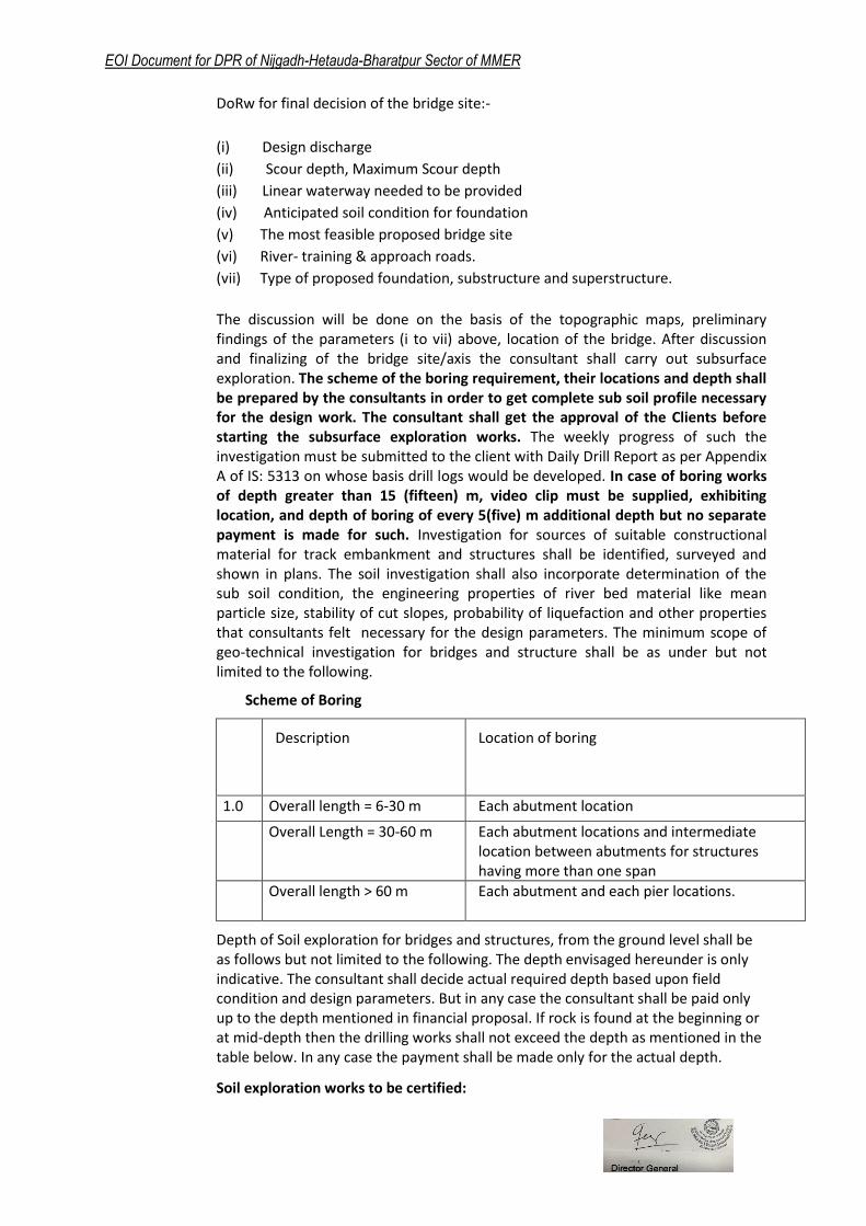
The discussion will be done on the basis of the topographic maps, preliminary findings of the parameters (i to vii) above, location of the bridge. After discussion and finalizing of the bridge site/axis the consultant shall carry out subsurface exploration. The scheme of the boring requirement, their locations and depth shall be prepared by the consultants in order to get complete sub soil profile necessary for the design work. The consultant shall get the approval of the Clients before starting the subsurface exploration works. The weekly progress of such the investigation must be submitted to the client with Daily Drill Report as per Appendix A of IS: 5313 on whose basis drill logs would be developed. In case of boring works of depth greater than 15 (fifteen) m, video clip must be supplied, exhibiting location, and depth of boring of every 5(five) m additional depth but no separate payment is made for such. Investigation for sources of suitable constructional material for track embankment and structures shall be identified, surveyed and shown in plans. The soil investigation shall also incorporate determination of the sub soil condition, the engineering properties of river bed material like mean particle size, stability of cut slopes, probability of liquefaction and other properties that consultants felt necessary for the design parameters. The minimum scope of geo-technical investigation for bridges and structure shall be as under but not limited to the following.
Scheme of Boring
S.N
Description Location of boring
1.0 Overall length = 6-30 m Each abutment location
2.0
Overall Length = 30-60 m Each abutment locations and intermediate location between abutments for structures having more than one span
3.
Overall length > 60 m Each abutment and each pier locations.
Depth of Soil exploration for bridges and structures, from the ground level shall be as follows but not limited to the following. The depth envisaged hereunder is only indicative. The consultant shall decide actual required depth based upon field condition and design parameters. But in any case the consultant shall be paid only up to the depth mentioned in financial proposal. If rock is found at the beginning or at mid-depth then the drilling works shall not exceed the depth as mentioned in the table below. In any case the payment shall be made only for the actual depth.
Soil exploration works to be certified:
EOI Document for DPR of Nijgadh-Hetauda-Bharatpur Sector of MMER
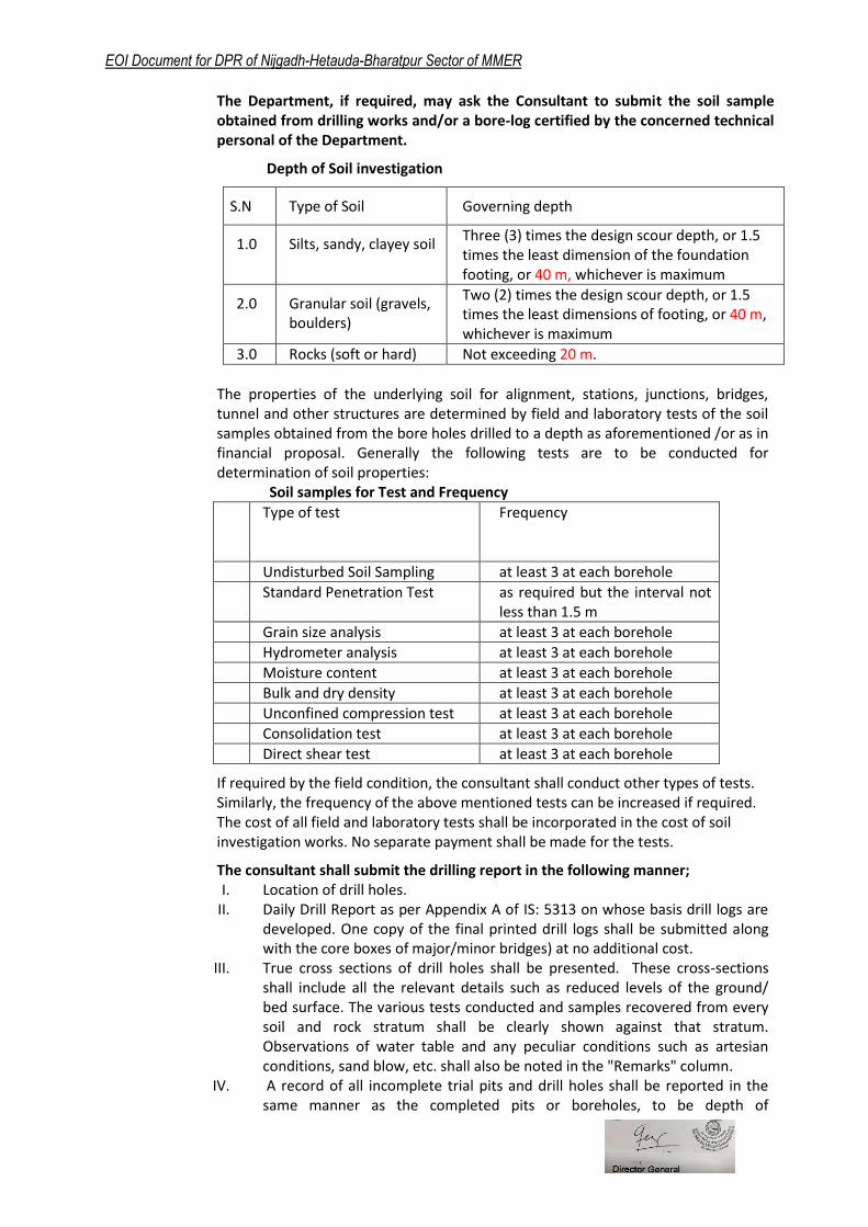
The Department, if required, may ask the Consultant to submit the soil sample obtained from drilling works and/or a bore-log certified by the concerned technical personal of the Department.
Depth of Soil investigation
S.N Type of Soil Governing depth
1.0 Silts, sandy, clayey soil Three (3) times the design scour depth, or 1.5 times the least dimension of the foundation footing, or 40 m, whichever is maximum
2.0 Granular soil (gravels, boulders)
Two (2) times the design scour depth, or 1.5 times the least dimensions of footing, or 40 m, whichever is maximum
3.0 Rocks (soft or hard) Not exceeding 20 m.
The properties of the underlying soil for alignment, stations, junctions, bridges, tunnel and other structures are determined by field and laboratory tests of the soil samples obtained from the bore holes drilled to a depth as aforementioned /or as in financial proposal. Generally the following tests are to be conducted for determination of soil properties:
Soil samples for Test and Frequency
Sn.
Type of test Frequency
1 Undisturbed Soil Sampling at least 3 at each borehole
2 Standard Penetration Test as required but the interval not less than 1.5 m
3 Grain size analysis at least 3 at each borehole
4 Hydrometer analysis at least 3 at each borehole
5 Moisture content at least 3 at each borehole
6 Bulk and dry density at least 3 at each borehole
7 Unconfined compression test at least 3 at each borehole
8 Consolidation test at least 3 at each borehole
9 Direct shear test at least 3 at each borehole
If required by the field condition, the consultant shall conduct other types of tests. Similarly, the frequency of the above mentioned tests can be increased if required. The cost of all field and laboratory tests shall be incorporated in the cost of soil investigation works. No separate payment shall be made for the tests.
The consultant shall submit the drilling report in the following manner; I. Location of drill holes.
II. Daily Drill Report as per Appendix A of IS: 5313 on whose basis drill logs are developed. One copy of the final printed drill logs shall be submitted along with the core boxes of major/minor bridges) at no additional cost.
III. True cross sections of drill holes shall be presented. These cross-sections shall include all the relevant details such as reduced levels of the ground/ bed surface. The various tests conducted and samples recovered from every soil and rock stratum shall be clearly shown against that stratum. Observations of water table and any peculiar conditions such as artesian conditions, sand blow, etc. shall also be noted in the "Remarks" column.
IV. A record of all incomplete trial pits and drill holes shall be reported in the same manner as the completed pits or boreholes, to be depth of
EOI Document for DPR of Nijgadh-Hetauda-Bharatpur Sector of MMER
investigation, along with an appropriate explanation for abandoning further investigation.
V. All geological features shall be prominently brought forward in these logs.
3.2.3 Geological and Geotechnical surveys and investigation for tunnels
The consultant shall study geological setup and geotechnical condition of project area on macro and micro level to optimize tunnel layout. The consultant shall collect sufficient geological & geotechnical data for design of tunnel support/rock support and required related other civil structures.
A. Surface Geological Investigation Surface geological investigation is the observational inquiry of the project site and thematic recording of the geological and geotechnical feature on two dimensional maps and sections of the project area. Lithological details of the proposed project can be gathered which gives fair idea about rock types available in the area. Tectonics, overall assessment of tectonic features such as thrust, major faults, and shear zones passing through the area shall be made. It is advisable to avoid such features at the proposed project site. Hence the consultant shall carryout the surface geological investigation covering the following details.
Regional Geological Study a. Collect and review available literature, topographical, regional geological
maps, geological sections and aerial photographs of the project region b. Prepare a report on regional geology and structure on the basis of existing
information c. Prepare regional geological maps with plan and section in 1:25,000 scale d. Finally conduct field survey for verification
General Geology and Geomorphology of the Project Area a. Review the regional geological maps and report geology and study the
geomorphology area b. General geological field survey/mapping and prepare detail general
geological maps with plan and section of the project area in 1:10,000 scale c. Prepare detail report on general geology and geomorphology of the
project area.
Engineering Geological Study of Particular Sites a. Conduct a detailed engineering geological mapping/survey of particular
site such as the tunnel portals and all along the tunnel alignment. b. Prepare a detailed engineering geological maps (plan and profile)
indicating all the major discontinuities, shear zones, fault, thrust, rock mass quality and rock class along the tunnel alignment for design requirements in 1:2000 scale.
c. Collect representative rock and soil samples for the require laboratory test, the required laboratory test shall be as per the list presented below.
Discontinuities Survey and Rock Mass Classification a. Conduct discontinuities survey such as bedding/ foliation planes,
lithological contacts major and minor joints sets, fault thrust and folds b. Tabulate all measured discontinuities along with location with their
occurrence

EOI Document for DPR of Nijgadh-Hetauda-Bharatpur Sector of MMER
c. Conduct discontinuities analysis by computer or other method to define major orientation such as stereographic projection and joint rose set diagram
d. Prepare analytical results in graphical format with respect to tunnel alignment and portal slope.
e. Conduct rock mass classification on the basis of RMR (Rock Mass Rating) and “Q” (Rock Mass Quality Index) and Geological Strength Index (GSI) system at the portal area and all along the tunnel alignment covering almost each 100m interval of the tunnel alignment and present systematically with the longitudinal geological profile of the tunnel alignment.
B. Sub-Surface Geological Investigation There are two types of sub-surface geological-geotechnical investigation methods in practice.
Indirect Sub-surface Geological investigation method and
Direct Sub-surface Geological investigation method
Indirect Subsurface Geological Investigation (Geophysical Investigation) Sub-surface geological investigation by geophysical method is called Indirect Sub-surface Investigation Method. The application of the geophysics for ground penetration and interpretation of the obtained data from the information passed through the subsurface strata provides its nature, type and quality of ground indirectly. Geophysical methods have been used to probe the soil properties and depth to interface between soil and bedrock, weak zones within the bedrock, to identify saturation and permeable zones. The response of the soils to the cyclic loading is important to know in geotechnical earthquake engineering to analyze the vibration during the passage of an earthquake wave. Among several geophysical methods the following two methods are commonly applying for the indirect sub-surface geological/geotechnical investigation, therefore it is recommended for this project also. The methods are as follows;
a. Seismic Refraction Tomography (SRT) Conventional method in seismic refraction is a 1-D method where layers in the subsurface are modelled as 1-D structures. In conventional seismic refraction the boundaries between different lithological units are considered to be discrete and sharp. However in real geological setup it is usual that there is some transformation zone from one lithological zone to another. It is usual to have smooth variation from one formation to another. Furthermore, conventional method of interpretation is based on the assumption that there is no velocity inversion in the subsurface. In some geological setup velocity inversion is frequent along the depth. Seismic Refraction Tomography (SRT) is the new method of data processing and interpretation in geophysical science. SRT is the new method of processing and interpretation which can model complex geological setup of the subsurface. Since SRT belongs to the geophysical imaging techniques we need to collect large volume of data as much as possible. There must be sufficient redundant coverage to record multiple paths of signal transmission and reception. To fulfil this requirement the number of shots needs to be increased. The objectives of SRT are as following:
To identify different geological layers related to overburden, rock mass zones related to different quality
To identify weak zones within the bedrock
EOI Document for DPR of Nijgadh-Hetauda-Bharatpur Sector of MMER
To identify water table
To identify weak zones with in overburden material of the slope for slope stability
b. Multichannel Analysis of Surface Waves (MASW) and Micro tremor Array Measurement (MAM) A new method of obtaining shear wave velocity information of the subsurface is known under the name MASW (Multi-channel Analysis of Surface Waves) and MAM (Micro tremor Array Measurement). MASW is the active source method and MAM is the passive source method. Sometime MAM is also called ReMi (Refraction Micro tremor). The end product of both active and passive methods is the shear wave velocity information of the subsurface. MASW can be 1D and 2D. Both MASW and MAM results can be combined to produce single shear wave profile. Shear wave velocity thus obtained can be used to calculate soil parameters such as modulus of elasticity, shear modulus, Poisson’s ratio, P-wave velocity and bearing pressure, predominant period and frequency of the surface layer, site classification for geotechnical earthquake engineering. Compression and shear wave velocities are the most powerful soil properties representing a family of geotechnical soil parameters, ranging from compressive and shear strengths to void ratio. Shear wave velocity determined for real soil condition represents the most reliable parameter than the material that has been removed from and tested in the laboratories or in-situ test made by other geotechnical means. Shear wave velocity represents the strength of the subsurface material. So, an empirical relation of the shear wave velocity with the allowable bearing pressure and unit weight of the soil has been established.
c. Electrical Resistivity Tomography (ERT) Survey The scope of the services (Electrical Resistivity Tomography (ERT) Survey to be provided by the Consultant shall be as follows:
2D-ERT survey shall be carried at different location of the project along the tunnel alignment and inlet and outlet portal location of the tunnel.
Make the measurements of sufficient electrical resistivity values along survey lines so that the data set fit to carry inversion for the preparation of 2D-Electrical Resistivity Tomography.
Measurement lines shall be jointly fixed with coordination of the Client's geologist.
The measurement should be carried out by using SYSCAL PRO SWITCH 48 which has multichannel receiving and high input impedance.
Data acquisition should be carried out to make detail cover of the subsurface. If the depth requirement is more than 70 m. 10 m spacing is allowed to make in other case electrode spacing should be less than 10 m. In case if the depth requirement is 50 m measurement shall be carried out at 5 m electrode spacing whereas if the depth requirement is between 50 m to 70 m measurement shall be carried out at 7 m spacing.
The consultant shall make regular data check-up for the data quality during the fieldwork. For this purpose consultant make the preliminary processing of the data in the field. Topographical survey crew shall be at

EOI Document for DPR of Nijgadh-Hetauda-Bharatpur Sector of MMER
site with the ERT team to provide the accurate survey data of all the profile line for to prepare the subsurface profile and interpretation.
Consultant shall process data to prepare resistivity tomograms of every profile where the 2D-ERT survey has been carried out.
The consultant shall also make geological/hydro geological interpretation of the 2D-ERT sections based on the concept developed by using surface geological observation and subsurface information of the electrical resistivity tomograms. These interpretations shall be presented as interpretative cross-sections.
Direct Subsurface Geological Investigation (Investigation by exploratory drilling an exploratory drifting)
a. Scope of Work This works required for detailed Geological geotechnical Investigation - Drilling that comprise Rotary Diamond drilling (NX size) through all types of subsurface strata with diamond bits and double/ triple tube core barrels, collection of core samples, conducting various tests including permeability tests and Standard Penetration tests in drill holes, and preparation of a detailed report. The work shall include mobilization of necessary equipment, providing necessary engineering supervisors, geologist and technical personnel, skilled and unskilled labour and such other services as required performing core drilling, field tests and collection of core samples. The work to be done shall be broadly in two parts: Drilling in Overburden and Drilling in Rock b. Codes and Standards All works shall be carried out strictly in accordance with the Technical Specifications, unless otherwise approved by the Client in writing. Where not specified, the latest edition of the applicable code of practice or procedure as laid down by the Bureau of Indian Standards (BIS) or similar other equivalent or higher standard in practice shall be followed.
C. Drilling Drilling Through Overburden (Soil) Drilling in overburden shall be carried out by driving casing of requisite size, or by method approved by the Client. Rigs shall be capable of drilling to required depth. Casing and/or bentonite/ mud slurry may be used to avoid caving. However, for those drill holes where water samples are to be collected for chemical analysis or field permeability tests are to be conducted, bentonite/ mud slurry shall not be used or shall be restricted as directed by the Client.
Drilling Through Rock I. In rock strata, drilling shall be done by using a rotary cutting tool tipped
with diamonds and equipped to recover cores. II. Generally the drill hole should be of NX size. In case of difficulty arising
due to strata in continuing the NX size the company shall take the approval of Client to reduce the size.
III. Core barrels shall normally be double/triple tube ball-bearing, swivel type, with the core lifter located in the lower end of the inner barrel.
IV. Drilling shall be carried out in such a manner that maximum core is

EOI Document for DPR of Nijgadh-Hetauda-Bharatpur Sector of MMER
recovered. This requires close surveillance of wash water, drilling pressures, rotational speed, lengths of runs etc. The drill bit shall be withdrawn and the core removed as often as may be necessary to secure the maximum possible amount of core. The consultant shall ensure that drilling is carried out with necessary skill and expertise.
V. Coring runs shall be limited to a maximum length of 1.5m. When less than 50% of the core is recovered from a run or when a geological feature is to be accurately determined, the length of the run shall be limited to 0.5 m unless directed otherwise by the Client.
VI. The core shall be removed from the drill hole immediately if blocking of the bit or grinding of the core is apparent, regardless of the length of run which has been made.
VII. The consultant shall not use drilling mud or any lubricant in the drill hole other than water.
VIII. The ease or difficulty of drilling at different depths shall be carefully noted and recorded during drilling. The returning drill water shall be kept constantly under observation and its character, such as, its clarity or its turbidity, its colour, etc. shall be recorded. If the returning drill water is turbid, the turbid drill water shall be collected and the suspended matter allowed settling. The settled matter shall be preserved in suitable containers and kept in the core box at the appropriate place corresponding to the depth from which it is obtained. Depth of drill water losses, partial or full, shall be accurately recorded during drilling.
IX. For each run, Core Recovery and Rock Quality Designation (RQD) shall be noted carefully, immediately after cores are taken out of the barrel.
X. Marking of core pieces: Each and every core piece shall be serially and sequentially numbered
from top downwards. The serial number shall be painted with only good quality enamel paint of yellow colour. Arrows indicating the lower end of the core piece and the number of drill hole shall also be painted on each core piece. Length of each core piece shall be measured and recorded.
XI. Storing of core pieces and core boxes: All core pieces shall be placed in core boxes in serial order in correct
sequences from top downwards. Core boxes shall be procured by the consultant conforming to the specifications laid down in IS: 4078 or equivalent or higher. Core boxes shall be made of good quality wood and be sturdy enough to withstand rough handling they are likely to be subjected to during drilling work, shifting, transport, storing, logging etc. Boxes shall be sequentially numbered in the sequence in which the boxes are used to store the core pieces. The following information shall be neatly painted on the lid of the core boxes, using pre-cut stencils:
Name of the project : Location of drill hole : Drill hole No. : Coder box No. : Depth of core contained from : m to m.
The drill hole no. and the core box no. shall also be painted on all four vertical sides with enamel paint.
XII. The end of each run shall be indicated within the compartments of the core box by placing a seasoned, insecticide treated and painted wooden block after the last core piece of that run. The depth at which the run ends shall also be painted on the partition between core box

EOI Document for DPR of Nijgadh-Hetauda-Bharatpur Sector of MMER
compartments with good quality enamel paint, in line with the wooden block.
XIII. Digital and printed colour photographs of the cores after putting in the core boxes for each borehole shall be taken by a professional photographer and shall be included in the report. Each photograph shall be taken in good light conditions and shall clearly show all the details of the drill hole number, location, depths as well as the core. The image shall clearly show the core runs and other lithological detail.
XIV. The core boxes shall be transported and stored in the core library at location specified by the Client or safely handover to the Client. The core boxes shall be stored in a series of racks in the core library and boxes after being painted and suitably captioned should be arranged in the racks according to the serial order. The daily drill reports received from the field should also be available for ready reference in the core library. Copies of detailed report on geological logs when finally prepared should be maintained in the core library, after proper indexing, so that these are readily available when required. Arranging in rocks and maintaining library is Client’s obligation.
XV. The cores, arranged in core boxes as noted above, shall be submitted to the Client on submission of the report
XVI. During the drilling operations if collapse or caving occurs in the drilled holes, the hole shall be consolidated to stabilize the sides by pouring cement/ bentonite grout the cost of which is included in financial proposal of suitable consistency through a pipe from the top as directed by the Client.
Drill Hole Location Marking Permanent markers, as directed by Client shall be established at all drill hole locations which is included in the drilling rates. This item includes providing all necessary personnel, materials like concrete including cement, sand, aggregates (fine and coarse), reinforcement, formwork water, threaded cap, etc. complete as per drawing and these materials shall conform to, the relevant IS codes or equivalent or higher. This also includes the painting of "Drill Hole No." on all four vertical sides of concrete block with enamel paint as directed by the Client. This also includes the threading of the casing pipe in the top portion Drill Hole Depth All holes shall be drilled to depths and inclination as per soil properties and conditions or as directed by the Client.
Sampling The consultant shall take samples and cores as specified in drawing or as directed by the Client. This operation shall include the provision of all necessary equipment, tubes and containers and materials. Standard procedures as per IS code or higher or equivalent should be followed.
Specific Observations during Drilling
Observations to be made by the consultant during drilling shall include but not be limited to the following:
a) Sequence and Thickness of Different Strata b) Groundwater Table and depth of occurrence c) "Loss" or "Make" of Drilling Fluid to be brought to the
EOI Document for DPR of Nijgadh-Hetauda-Bharatpur Sector of MMER
notice of Client d) Presence of Lime, Mica etc. e) Depth at which drill hole was grouted as per IS: 5313 or equivalent f) Artesian condition as per IS: 5313 or equivalent g) Gas discharge as per IS: 5313 or equivalent h) Other observations as per IS: 5313 or equivalent i) Recording of observations as per IS: 5313
D. Tests in a Drill Hole
Standard Penetration Test (SPT) Penetrometric SPT or DCPT tests shall be carryout during the drilling through soil; in every 3m interval for the first 20 m below ground level and every 10 m at greater depth, or wherever, the soil conditions; grain size in particular, will allow their execution. The consultant shall equip themselves to conduct SPT in drill holes, where ever required as directed by Client. The test should be conducted as per relevant BIS code or equivalent or higher.
Permeability Test Test in Overburden The consultant shall carry out field permeability tests in overburden, at specified depths or as directed by the Client, as variable head (rising or falling head) and/or constant head method in every 5m interval down to the depth during the drilling. This test shall not be conducted in that portion of borehole in which bentonite or drilling mud has been circulated. If external water is to be added to borehole as in constant head test, only clear water shall be used. Test in Rock (Packer Test) Permeability test in rock, at depths specified, shall be carried out as a Packer Test. Single or double packer, as required, shall be used. Preference shall be given to single packer type of test. Hence at different depths, the tests shall be conducted progressively as the drill hole is advanced in every 5m interval down to the depth during drilling using single packer. The type of packer to be used shall be such as to give a tight fit. The difference between the borehole and packer diameter shall not exceed 6mm. The maximum pressure to be applied in a test should equal to standard head of 100m above the groundwater level, unless approved otherwise by the Client. This value of maximum pressure may be reduced if it is likely to cause uplift of the ground or to break the seal of the packer in weak rock. The test shall be conducted as a series of tests, at a given depth, at different pressures. A series of 3 tests is desirable with the maximum pressure applied in three equal increments and then reduced with decrements of the same amount. Double packer tests may have to be carried out as directed by the Client in case of excessive permeability. A complete record of all observations shall be presented in lugeons.
Instrumentation The consultant may be required to provide, install and/or take observations from instrumentations such as piezometers where ever required, as per details furnished in relevant drawing or as directed by Client.
Progressive Submission of Field Data

EOI Document for DPR of Nijgadh-Hetauda-Bharatpur Sector of MMER
The consultant shall submit progressively two copies of data from the field work. As soon as each drill hole is completed, the drill log with all relevant field details and the in-situ test results shall be submitted. In addition to submission of field data, the consultant shall submit every week progress achieved during the previous week and cumulative progress to that date and shall also indicate likely date for completion of field work.
E. Report The consultant shall submit the drilling report in the following manner;
I. Location of drill holes. II. Daily Drill Report as per Appendix A of IS: 5313 on whose basis drill logs are
developed. One copy of the final printed drill logs shall be submitted along with the core boxes at no additional cost.
III. True cross sections of drill holes shall be presented. These cross-sections shall include all the relevant details such as reduced levels of the ground/ bed surface. The various tests conducted and samples recovered from every soil and rock stratum shall be clearly shown against that stratum. Observations of water table and any peculiar conditions such as artesian conditions, sand blow, etc. shall also be noted in the "Remarks" column.
IV. A record of all incomplete trial pits and drill holes shall be reported in the same manner as the completed pits or boreholes, to be depth of investigation, along with an appropriate explanation for abandoning further investigation.
V. All geological features shall be prominently brought forward in these logs.
Laboratory Test The consultant shall select the appropriate and adequate no. of samples during the surface geological mapping and exploratory drilling (drill core sample of rock, random sample of rock and soil) and shall carry out the following laboratory tests.
Tests on Soil Samples
Soil Classification
Mineralogical and Petrographical analysis
Specific gravity
Organic Content
Complete sieve analysis
Atterberg Limits (particle<0.425 mm)
Oedometric Test (loading steps 50, 100, 200,400 and 800 kPa)
Triaxial test UNDRAINED conditions (recomposed soil density 1.5t/m2)
Direct Shear Test (test cohesion and friction angle) 100, 200, and 400 kPa)
Tests on Rock Samples
Rock Identification
Mineralogical and Petrographical analysis
Specific gravity
Specific weight
Porosity
Brazilian test
Los Angeles abrasion test
Alkali reaction potential test
Point load test on random rock sample
EOI Document for DPR of Nijgadh-Hetauda-Bharatpur Sector of MMER
Uniaxial Compressive Strength (with Young’s modulus and Poisson ratio determination, test perpendicular to the foliation plain).
Uniaxial Compressive Strength (with Young’s modulus and Poisson ratio determination, test parallel to the foliation plain)
Study the Seismic Hazard Analysis of the project Region The main objective of the Seismic Hazard Analysis is estimation of design ground motion parameter for the design of engineering structures. The scopes of work shall be as follows but not limited to;
Probabilistic Seismic Hazard Analysis.
Construction of hazard curves.
Construction of Design Spectra
Estimation of Design Basis Earthquake (DBE).
Estimation of Operating Basis Earthquake (OBE).
Deterministic Seismic Hazard Analysis.
Estimation of Maximum Credible Earthquake (MCE) of each earthquake source.
Identification of Maximum Considered Earthquake.
One-dimensional response analysis at the site.
H. Hydro geological Investigations The following hydro geological investigation shall be carried out during the geological and geotechnical investigation of the project
Survey of rivers – Annual flow monitoring
Survey of springs – Annual flow monitoring
Groundwater level – Annual level monitoring
Chemical water analysis
Restrictions by protected areas for groundwater resources
Groundwater temperature
The cost of all field and laboratory tests shall be incorporated in the cost of Geological and Geotechnical surveys and investigation for tunnels works. No separate payment shall be made for the tests
3.2.3 Hydrological Survey
The Consultants shall carryout detail hydrological survey based on the analysis of the rainfall and flood records, supplemented by engineering field investigations necessary for detail design of track formation, approach road embankment, bridges, culverts, longitudinal drainage, tunnels and other structures, design bed and protection works including river training works for drainage structures and bridges.
For determination of all design data the consultant shall carry out a detailed
hydrometrical survey and hydrological study of the river, bridge and other structure site,
which shall include the following:
(i) Catchment area of the river up to bridge site
(ii) Length of the river from origin up to bridge site
(iii) Possibility of change of catchment
(iv) Nature, size and quantities of debris carried by the river
(v) Intensity, duration and distribution of rain in the catchment
(vi) Vegetation, cultivation etc. of the catchment.
EOI Document for DPR of Nijgadh-Hetauda-Bharatpur Sector of MMER
(vii) Existence of reservoir's, Lakes etc. in the catchment.
(viii) Existing bridge or other hydraulic structures across the river in the vicinity of the
proposed bridge site with their details as much as possible.
(ix) General slope of the river from the critical point (origin) of the river up to bridge
site and general slope of the catchment in both sides of the river.
(x) Cross sections covering 200m. beyond flood lines of the river at proposed bridge
site, at about 500m. u/s and about 200m d/s. wherein HFL, LWL, LBL, area of the
cross section, wetted perimeter and geological profile with silt factor of each
strata (at proposed bridge site only) shall be indicated. (horizontal and vertical
scale of the cross section shall be the same. )
(xi) Bed slope of the river which must start from 100m. up of the u/s cross section and
end at 100 m. down of the d/s. cross section.
(xii) Maximum discharge calculated by established formulas with different return
periods and the peak discharge observed over a period of 100 years.
(xiii) Velocity and depth of flow at the time of survey.
(xiv) Shifting of the river in the past at proposed bridge site and in its vicinity.
(xv) Other information required for river control, design, construction and
maintenance of the bridge.
3.2.4 Detail Design of Civil Structures
The Consultant shall carryout detail design and drawing of the railway tracks, formation, road pavement , bridges and river training works, level crossing and track isolation, ROB, RUB, tunnels, all drainage and protection structures, blanketing, trolley refuges etc.
3.2.5 Station Building, Station platforms, Office & Service buildings, Residential Quarters, Sheds & Workshops
The Feasibility Study has mentioned the requirement number of railway stations. The Consultant shall identify station locations and prepare typical master plans one for general stations which shall include the above mentioned facilities as required. The consultant shall then prepare specific location plans, preliminary architectural plans and elevations for approval of the Client. The proposed station complex and facilities should be adequate to cater future needs. After getting the approval of the Client, consultant shall prepare detail design and drawings of the station complex and the facilities which shall include the following:
Conduct detailed topographic survey of the site. The survey shall also include all necessary data related to the existing public utility services, lines of streets and pavements, building lines, adjoining properties, restrictions and boundaries necessary to design of sewerage and storm water drainage system;
Conduct necessary soil test, hydrological survey and such other tests required to provide essential data from sub-soil conditions
Detail architectural design and drawings of the complex including typical buildings and facilities, layout plan, land developments and landscaping for individual station complex,
Detail structural design and drawings
Detail sanitary, plumbing, drainage, water supply and sewerage system designs including solid waste management
EOI Document for DPR of Nijgadh-Hetauda-Bharatpur Sector of MMER
Detail electrical, electronic, communication systems and internet system design;
Heating, ventilation, and air conditioning design (HVAC) and mechanical systems designs;
Design of fire detection, fire protection and security system etc.;
Design of disaster management system;
Maintenance arrangements for the infrastructure proposed to be constructed;
3.2.6 Electrical Power Supply & Traction, Signaling, Train control and Communication systems
The consultants shall carryout design and drawings for traction, train control. Communication system on the basis of the preliminary design recommendation made in the Feasibility Study and or improvements suggested by the consultants and approved by the Client. The electrical power supply system shall be designed and engineered based on the equipment being continuously in operation. The proposed capacities, ratings and safety requirements for the traction power supply and auxiliary power distribution shall be designed with reference to good industry practice. The overall power factor of electrical supplies be in conformance with power supply authorities stipulations. The power supply system for the stations requirement shall be so designed to support the system operations, as per the operation plan. All designs shall be based on performance requirements. Signaling and train control system shall be designed comprising, automatic train protection system, automatic train supervision system and automatic train operation system. The design of the telecommunication shall have the features of reliability and maintainability.
3.2.7 Rolling Stock
The consultant shall provide, on the basis of feasibility study recommendation or improvements suggested by the consultant and approved by the client, various design parameters and technology option for the rolling stock and also provide the cost of technology. Rolling stock costs for various technologies shall be obtained directly from equipment manufacturers.
3.2.8 Project Implementation and Operation Schedule
The consultant shall prepare Project Implementation and Operation Schedule, which shall include the Operation cost, maintenance frequency, operation timetable, plans to reduce mean time to restore the inventory, etc. The Consultant shall also provide detailed operating costs that are based on the ridership, and suggested operating timetable. The operating unit costs will include, i) Track maintenance, ii) Staff salary and facilities, iii) Rolling stock maintenance, iv) Electrical maintenance, v) Signals and communications maintenance, vi) Energy costs (breakdown of power for traction and ancillary power such as signaling, lighting, terminal, etc.) and, viii) Inventory Plan to reduce mean time to restore the failures in service affecting equipment.
3.2.9 Social Impact Assessment
The Consultant shall conduct social impact assessment especially the persons affected due to the Project and requiring resettlement and rehabilitation. GoN rehabilitation and resettlement guidelines shall be the basis for undertaking the assessment. Plan for resettlement and land acquisition shall be prepared, which shall include the following:
draft Resettlement and Land Acquisition Plan;

EOI Document for DPR of Nijgadh-Hetauda-Bharatpur Sector of MMER
The social assessments should include gender and local aspects;
scope and magnitude of likely resettlement and land acquisition effects, likely losses of households, lands, business and income opportunities, as well as affected community assets and public buildings;
development of an entitlement matrix i) in consultation with local stakeholders, government and the Authority, ii) socio-economic surveys, and iii) inventories of losses that will determine the amount of compensation in accordance with the guidelines and policies of the Government;
3.2.10 Environment Impact Assessment
The Consultant shall undertake environment impact assessment of the Project as per provisions of applicable Laws on environment protection of Government of Nepal and identify a package of measures to reduce/eliminate the adverse impact identified during the assessment. An environmental impact assessment (EIA) report and environmental management plan (EMAP) shall be prepared based on such assessment. The EMAP shall include project specific mitigation and monitoring measures for identified impacts as well as management and monitoring plans to address them. The Consultant shall also assist the authority in conducting public hearings and addressing the comments and suggestions received during the EIA process for getting environmental clearance from the competent authority.
3.2.11 Transfer of Technology
Nepal owes nearly eighty five years' history of operation of railway but possesses short of competent human resources for the planning, construction and operation of railway due to government’s shadowed priority on this sector. But now, relevancy of mass transport system to facilitate public transportation for socio-economic transformation has urged nation to step forward in the development and construction of railway infrastructure in the country. Development, construction, operation and other activities related to railway network and infrastructure will not be achieved unless capacity and capability of railway authority is enhanced by supplement of competent human resources. Hence, the consultant shall advise suitable human resource development plan and policy. Beside, the consultant’s proposal shall vividly depict suitable approach, methodology, effective incorporation of capacity building and skill enhancement measures via trainings, workshops, seminars etc., of human resources personnel of railway authority to ensure effective execution of railway development plan.
3.3 TECHNICAL SPECIFICATIONS
The Consultant shall prepare detail technical specification for each work item taking into account relevant international specification and practices with due consideration to the specifications in use in neighboring countries for similar works.
3.4 PROJECT COST/FINANCING OPTIONS On the basis of the detail design, drawings and specifications the consultant shall prepare analysis of rates for each work item and detailed cost estimate of various components with explanatory significance in terms of value engineering and prepare cost estimate of the project with a break up of cost of each component separately. The consultant shall recommend project financing options including potential for private sector participation in the construction of the project facilities including implementation strategy and institutional arrangement.
3.5 CONTRACT PACKAGING, BILL OF QUANTITIES AND TENDER DOCUMENTS
The consultant shall prepare appropriate contract packaging, Bill of Quantities (BOQ) and tender documents based on detail engineering design, drawing and specifications.
EOI Document for DPR of Nijgadh-Hetauda-Bharatpur Sector of MMER
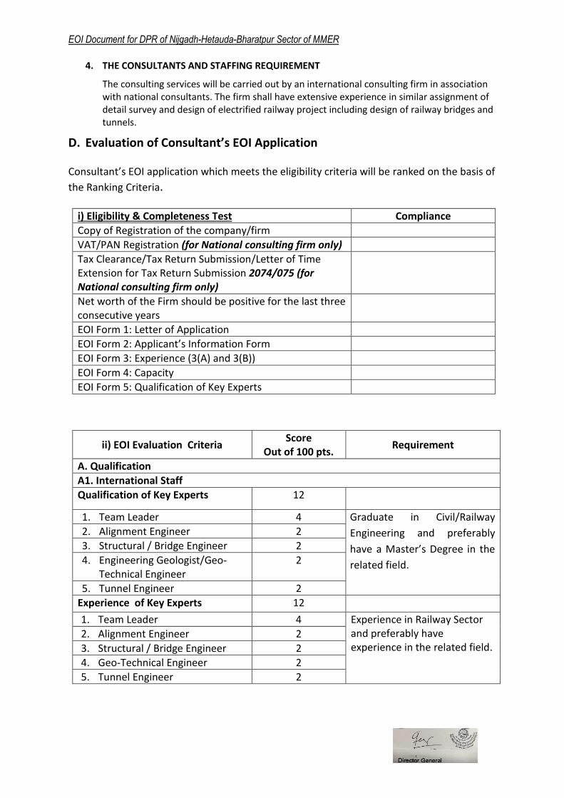
4. THE CONSULTANTS AND STAFFING REQUIREMENT
The consulting services will be carried out by an international consulting firm in association with national consultants. The firm shall have extensive experience in similar assignment of detail survey and design of electrified railway project including design of railway bridges and tunnels.
D. Evaluation of Consultant’s EOI Application Consultant’s EOI application which meets the eligibility criteria will be ranked on the basis of
the Ranking Criteria.
i) Eligibility & Completeness Test Compliance
Copy of Registration of the company/firm
VAT/PAN Registration (for National consulting firm only)
Tax Clearance/Tax Return Submission/Letter of Time Extension for Tax Return Submission 2074/075 (for National consulting firm only)
Net worth of the Firm should be positive for the last three consecutive years
EOI Form 1: Letter of Application
EOI Form 2: Applicant’s Information Form
EOI Form 3: Experience (3(A) and 3(B))
EOI Form 4: Capacity
EOI Form 5: Qualification of Key Experts
ii) EOI Evaluation Criteria Score
Out of 100 pts. Requirement
A. Qualification
A1. International Staff
Qualification of Key Experts 12
1. Team Leader 4 Graduate in Civil/Railway
Engineering and preferably
have a Master’s Degree in the
related field.
2. Alignment Engineer 2
3. Structural / Bridge Engineer 2
4. Engineering Geologist/Geo-Technical Engineer
2
5. Tunnel Engineer 2
Experience of Key Experts 12
1. Team Leader 4 Experience in Railway Sector and preferably have experience in the related field.
2. Alignment Engineer 2
3. Structural / Bridge Engineer 2
4. Geo-Technical Engineer 2
5. Tunnel Engineer 2

EOI Document for DPR of Nijgadh-Hetauda-Bharatpur Sector of MMER
A2. National Staff
Qualification of Key Experts 9.00
1. Deputy Team Leader 3.00 Graduate in Civil/Railway Engineering and preferably have a Master’s Degree in the related (for DTL Highway /Railway Engineering) field.
2. Structural / Bridge Engineer 2.00
3. Engineering Geologist/ Geotechnical Engineer
2.00
4. Tunnel Engineer 2.00
Experience of Key Experts 9.00
1. Deputy Team Leader 3.00 Experience in Railway/ Highway/Bridge/Tunnel Sector.
2. Structural / Bridge Engineer 2.00
3. Engineering Geologist/ Geotechnical Engineer
2.00
4. Tunnel Engineer 2.00
B. Experience
General experience 13
General experience of the consultants in Civil /RailwayEngineering Projects
Specific experience of consulting firm within last 7 years.
30 Rail Projects Railway Bridge Projects Railway/Metrorail Tunnel Projects
Similar Geographical experience of consulting firm
5 Experience in SAARC Countries, Out of SAARC ASIA and Any other countries (difference than nation of incorporation)
C. Capacity
Financial Capacity 10
Average Annual turnover equal to or greater than US$4.2 million 10.00 pts.

EOI Document for DPR of Nijgadh-Hetauda-Bharatpur Sector of MMER
E. EOI Forms & Formats
Form 1. Letter of Application
Form 2. Applicant’s information
Form 3.Experience (General, Specific and Geographical)
Form 4. Capacity
Form 5. Qualification of Key Experts

EOI Document for DPR of Nijgadh-Hetauda-Bharatpur Sector of MMER
1. Letter of Application
(Letterhead paper of the Applicant or partner responsible for a joint venture, including full postal address, telephone no., fax and email address)
Date: ...............................
To,
Full Name of Client: __________________________
Full Address of Client: ________________________
Telephone No.: ______________________________
Fax No.: ____________________________________
Email Address: _______________________________
Sir/Madam,
1. Being duly authorized to represent and act on behalf of (hereinafter "the Applicant"), and having reviewed and fully understood all the short-listing information provided, the undersigned hereby apply to be short-listed by [Insert name of Client) as Consultant for {Insert brief description of Work/Services}.
2. Attached to this letter are photocopies of original documents defining:
a) the Applicant's legal status;
b) the principal place of business;
3. [Insert name of Client] and its authorized representatives are hereby authorized to verify the statements, documents, and information submitted in connection with this application. This Letter of Application will also serve as authorization to any ind ividual or authorized representative of any institution referred to in the supporting information, to provide such information deemed necessary and requested by yourselves to verify statements and information provided in this application, or with regard to the resources, experience, and competence of the Applicant.
4. [Insert name of Client) and its authorized representatives are authorized to contact any of the signatories to this letter for any further information.1
5. All further communication concerning this Application should be addressed to the following person,
[Person]
[Company]
[Address]
1 Applications by joint ventures should provide on a separate sheet, relevant information for each party to the
Application.
EOI Document for DPR of Nijgadh-Hetauda-Bharatpur Sector of MMER
[Phone, Fax, Email]
6. We declare that, we have no conflict of interest in the proposed procurement proceedings and we have not been punished for an offense relating to the concerned profession or business and our Company/firm has not been declared ineligible.
7. We further confirm that, if any of our experts is engaged to prepare the TOR for any ensuing assignment resulting from our work product under this assignment, our firm, JV member or sub-consultant, and the expert(s) will be disqualified from short-listing and participation in the assignment.
8. The undersigned declares that the statements made and the information provided in the duly completed application are complete, true and correct in every detail.
Signed :
Name :
For and on behalf of (name of Applicant or partner of a joint venture):

EOI Document for DPR of Nijgadh-Hetauda-Bharatpur Sector of MMER
2. Applicant’s Information Form
(In case of joint venture of two or more firms to be filled separately for each constituent member)
1. Name of Firm/Company:
2. Type of Constitution (Partnership/ Pvt. Ltd/Public Ltd/ Public Sector/ NGO)
3. Date of Registration / Commencement of Business (Please specify):
4. Country of Registration:
5. Registered Office/Place of Business:
6. Telephone No; Fax No; E-Mail Address
7. Name of Authorized Contact Person / Designation/ Address/Telephone:
8. Name of Authorized Local Agent /Address/Telephone:
9. Consultant’s Organization:
10. Total number of staff:
11. Number of regular professional staff:
(Provide Company Profile with description of the background and organization of the Consultant and, if applicable, for each joint venture partner for this assignment.)

EOI Document for DPR of Nijgadh-Hetauda-Bharatpur Sector of MMER
3. Experience
3(A). General Work Experience
(Details of assignments undertaken. Each consultant or member of a JV must fill in this form.)
S. N.
Name of assignment
Location Value of
Contract
Year
Completed
Client Description of work carried out
1.
2.
3.
4.
5.
6.
7.
EOI Document for DPR of Nijgadh-Hetauda-Bharatpur Sector of MMER
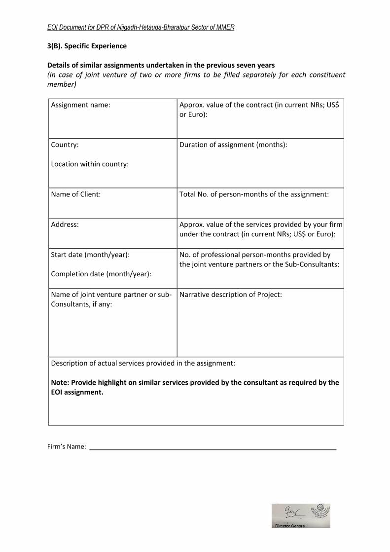
3(B). Specific Experience Details of similar assignments undertaken in the previous seven years (In case of joint venture of two or more firms to be filled separately for each constituent member)
Assignment name:
Approx. value of the contract (in current NRs; US$ or Euro):
Country: Location within country:
Duration of assignment (months):
Name of Client:
Total No. of person-months of the assignment:
Address:
Approx. value of the services provided by your firm under the contract (in current NRs; US$ or Euro):
Start date (month/year): Completion date (month/year):
No. of professional person-months provided by the joint venture partners or the Sub-Consultants:
Name of joint venture partner or sub-Consultants, if any:
Narrative description of Project:
Description of actual services provided in the assignment: Note: Provide highlight on similar services provided by the consultant as required by the EOI assignment.
Firm’s Name:

EOI Document for DPR of Nijgadh-Hetauda-Bharatpur Sector of MMER
3(C). Geographic Experience Experience of working in similar geographic region or country
(In case of joint venture of two or more firms to be filled separately for each constituent
member)
No
Name of the Project Location (Country/ Region)
Execution Year and Duration
1.
2.
3.
4.
5.
6.
7.
EOI Document for DPR of Nijgadh-Hetauda-Bharatpur Sector of MMER
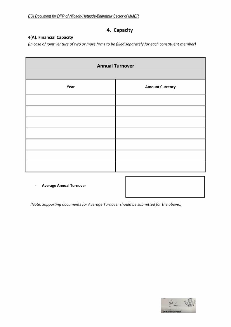
4. Capacity
4(A). Financial Capacity
(In case of joint venture of two or more firms to be filled separately for each constituent member)
Annual Turnover
Year Amount Currency
- Average Annual Turnover
(Note: Supporting documents for Average Turnover should be submitted for the above.)

EOI Document for DPR of Nijgadh-Hetauda-Bharatpur Sector of MMER
5. Key Experts (Include details of Key Experts only)
(In case of joint venture of two or more firms to be filled separately for each constituent
member)
International
SN Name Position Highest
Qualification
Work Experience
(in year)
Specific Work Experience
(in year) Nationality
1 Team Leader
2 Alignment Engineer
3 Structural / Bridge Engineer
4 Engineering Geologist/Geo-Technical Engineer
5 Tunnel Engineer
National
SN Name Position Highest
Qualification
Work
Experience
(in year)
Specific Work
Experience (in
year)
1 Deputy Team Leader
2 Structural / Bridge Engineer
3
Engineering Geologist/
Geotechnical Engineer
4 Tunnel Engineer


![Expression of Interest [EOI] Document for Prequalification ...](https://static.fdocuments.us/doc/165x107/61f3f83a4d12ef2602590844/expression-of-interest-eoi-document-for-prequalification-.jpg)

![Expression of Interest [EOI] Document for Pre ...](https://static.fdocuments.us/doc/165x107/61f11348edf2ae39e35aed6f/expression-of-interest-eoi-document-for-pre-.jpg)