Explosionproof Enclosures With Threaded Cover · Explosionproof Enclosures With Threaded Cover ......
15
6A–1 213 T: 216.267.9000 • F: 216.267.1681 • [email protected] • www.adalet.com ADALET Enclosure Systems • Designing Our Products Around Yours SM Explosionproof Enclosures With Threaded Cover Applications: • Adalet Junction Boxes and Instrument Housings are designed for installation in electrical conduit systems for hazardous environments. • Wiring: Pull boxes, splices, taps and terminal strips. • Housing for apparatus, instruments and other equipment. Features • Rugged sand-cast aluminum copper-free alloy — 0.3% max. copper content. • Tumblasted for quality appearance. • Cast-on mounting lugs, ease of field installation. • Grounding screw standard. Options • NEMA 3, 4 available; Features installation of an O-ring gasket on cover. • Conduit openings available, drilled and tapped to customer requirements. • Cast-on mounting buttons, bosses and pads available. Notes: Where reference is made to Class I and Class II hazardous locations, the equipment is suitable for use in both Division 1 and Division 2 hazardous locations. Solid Threaded Cover Threaded Dome Cover Threaded Glass Cover 15599 Sec.6 12/9/01 11:10 AM Page 213
Transcript of Explosionproof Enclosures With Threaded Cover · Explosionproof Enclosures With Threaded Cover ......
6A–1
213
T: 216.267.9000 • F: 216.267.1681 • [email protected] • www.adalet.comADALET Enclosure Systems • Designing Our Products Around YoursSM
Explosionproof Enclosures With Threaded Cover
Applications:• Adalet Junction Boxes and Instrument Housings are designed for installation in
electrical conduit systems for hazardous environments.• Wiring: Pull boxes, splices, taps and terminal strips.• Housing for apparatus, instruments and other equipment.
Features• Rugged sand-cast aluminum copper-free alloy — 0.3% max. copper content.
• Tumblasted for quality appearance.
• Cast-on mounting lugs, ease of field installation.
• Grounding screw standard.
Options• NEMA 3, 4 available; Features installation of an O-ring gasket on cover.
• Conduit openings available, drilled and tapped to customer requirements.
• Cast-on mounting buttons, bosses and pads available.
Notes:
Where reference is made to Class I and Class II hazardous locations, theequipment is suitable for use in both Division 1 and Division 2 hazardouslocations.
Solid Threaded Cover Threaded Dome Cover Threaded Glass Cover
15599 Sec.6 12/9/01 11:10 AM Page 213
6A–2
214
T: 216.267.9000 • F: 216.267.1681 • [email protected] • www.adalet.comADALET Enclosure Systems • Designing Our Products Around YoursSM
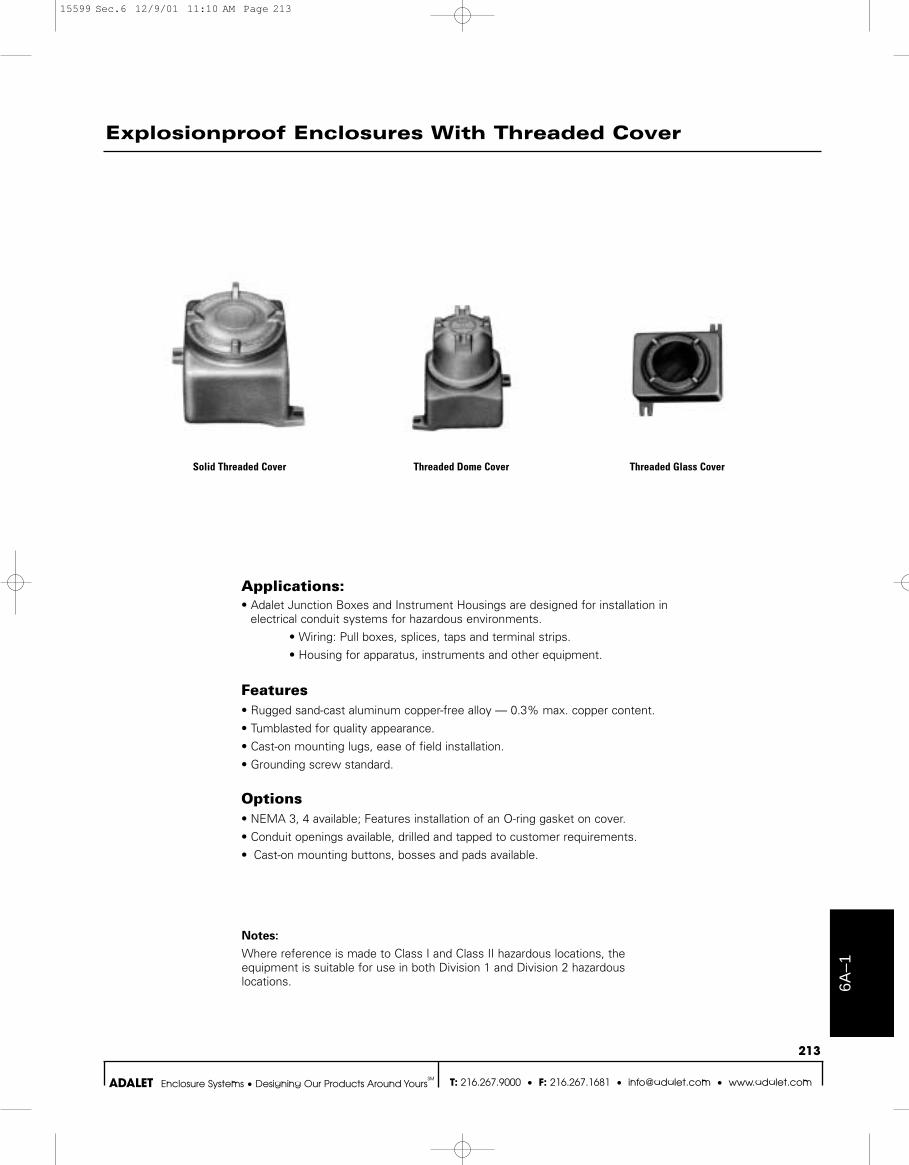
Explosionproof Enclosures With Threaded Cover
CLASS I GROUPS C & D; CLASS II GROUPS E, F, & G; NEMA 3, 4 (optional); NEMA 7, 9
Compliance
• NEC Class I, Groups C & D, Class II, Groups E, F & G
• UL Standard 1203• Investigated to CSA Standard C22.2
No. 30 by ULDrilled and tapped to specification, attach layout sheet.
XJD XJDA XJS(Can be tapped on
side pads only)
XJL XJT
XJHAXJMCXJMAXJMXJX
XJKAXJKXJHBXJHC
XJWH XJWT
XJN
Certifications
15599 Sec.6 12/9/01 11:11 AM Page 214
6A–3
215
T: 216.267.9000 • F: 216.267.1681 • [email protected] • www.adalet.comADALET Enclosure Systems • Designing Our Products Around YoursSM
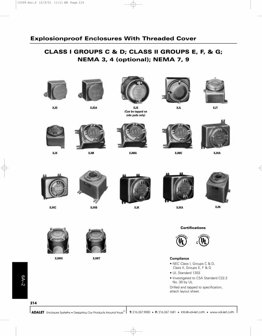
Explosionproof Enclosures With Threaded Window Cover
METER AND INSTRUMENT HOUSINGSEXPLOSIONPROOF AND DUST-TIGHT
CLASS I, GROUPS C & D; CLASS II GROUPS E, F, & G; NEMA 3, 4 (optional); NEMA 7, 9
XJDGCXJDFGC*
XJMCGC* XJTGCXJTFGC*
* includes internal flange and meter mounting plate.
XJMGC* XJMAGC* XJXGC XJLGC
XJHCGCXJHBGCXJHAGC
**XJOGC
XJKGC XJKAGC
XJWHGC XJWTGC
Compliance
• NEC Class I, Groups C & D, Class II, Groups E, F & G
• UL Standard 1203 • Investigated to CSA Standard C22.2
No. 30 by ULDrilled and tapped to specification, attach layout sheet.
**XJOGC Enclosure is UL Classified andCSA Certified
XJNGC 6 & 12
Back wall mounting plates optionalon some housings. Consult factory.
Certifications
15599 Sec.6 12/9/01 11:11 AM Page 215
6A–4
216
T: 216.267.9000 • F: 216.267.1681 • [email protected] • www.adalet.comADALET Enclosure Systems • Designing Our Products Around YoursSM
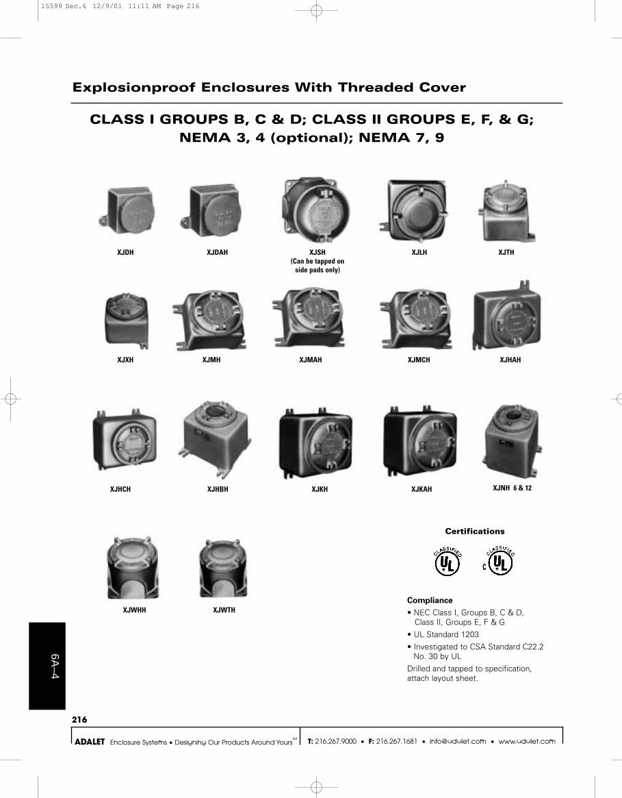
Explosionproof Enclosures With Threaded Cover
CLASS I GROUPS B, C & D; CLASS II GROUPS E, F, & G; NEMA 3, 4 (optional); NEMA 7, 9
Compliance
• NEC Class I, Groups B, C & D, Class II, Groups E, F & G
• UL Standard 1203• Investigated to CSA Standard C22.2
No. 30 by ULDrilled and tapped to specification, attach layout sheet.
XJDH XJDAH XJSH(Can be tapped on
side pads only)
XJLH XJTH
XJHAHXJMCHXJMAHXJMHXJXH
XJKAHXJKHXJHBHXJHCH
XJWHH XJWTH
XJNH 6 & 12
Certifications
15599 Sec.6 12/9/01 11:11 AM Page 216

6A–5
217
T: 216.267.9000 • F: 216.267.1681 • [email protected] • www.adalet.comADALET Enclosure Systems • Designing Our Products Around YoursSM
Explosionproof Enclosures With Threaded Window Cover
METER AND INSTRUMENT HOUSINGSEXPLOSIONPROOF AND DUST-TIGHT
CLASS I, GROUPS B, C & D; CLASS II GROUPS E, F, & G; NEMA 3, 4 (optional); NEMA 7, 9
XJDGCHXJDFGCH*
XJMCGCH* XJTGCHXJTFGCH*
XJMGCH* XJMAGCH* XJXGCH XJLGCH
XJHCGCHXJHBGCHXJHAGCH XJKGCH XJKAGCH
XJWHGCH XJWTGCH
Compliance
• NEC Class I, Groups B, C & D, Class II, Groups E, F & G
• UL Standard 1203• Investigated to CSA Standard C22.2
No. 30 by ULDrilled and tapped to specification, attach layout sheet.
XJNGCH 6 & 12
Back wall mounting plates optionalon some housings. Consult factory.
Certifications
* includes internal flange and meter mounting plate.
15599 Sec.6 12/9/01 11:11 AM Page 217
Certifications
6A–6
218
T: 216.267.9000 • F: 216.267.1681 • [email protected] • www.adalet.comADALET Enclosure Systems • Designing Our Products Around YoursSM
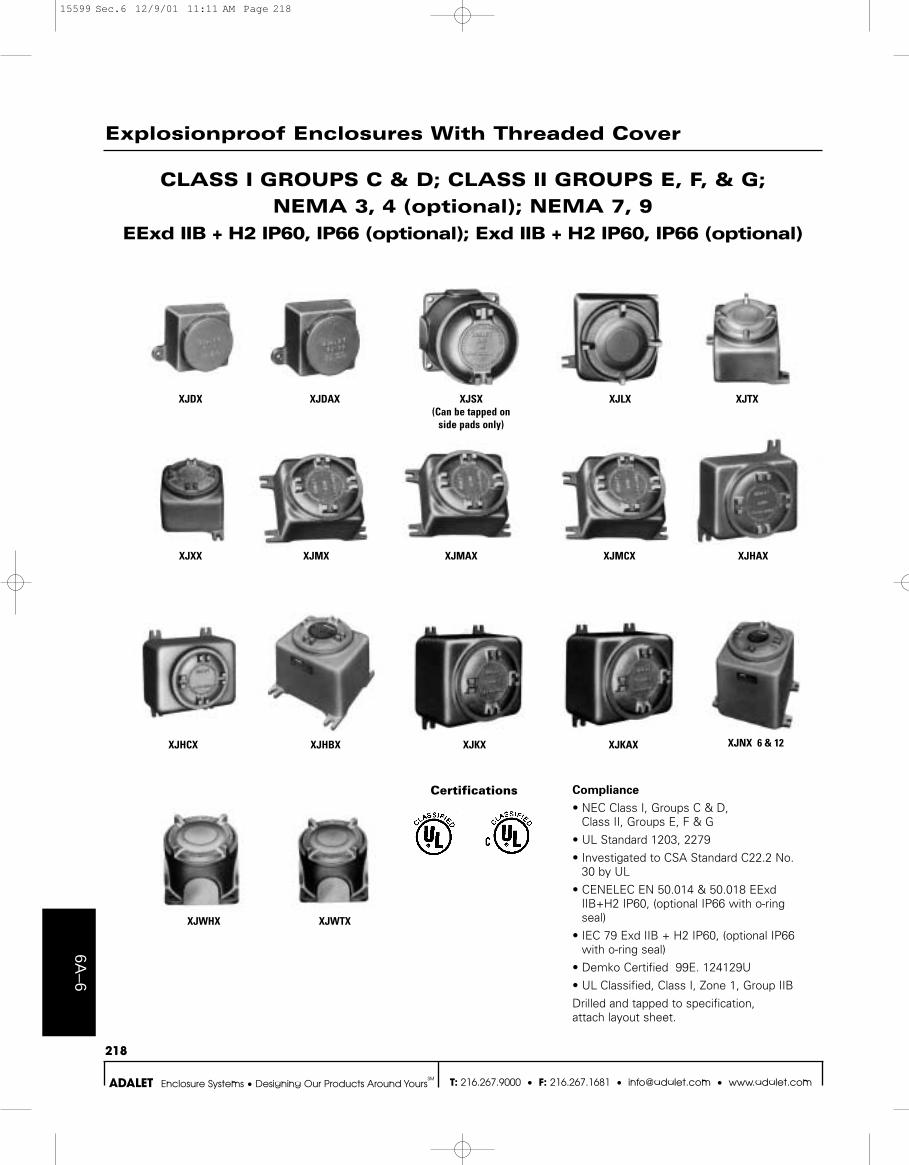
Explosionproof Enclosures With Threaded Cover
CLASS I GROUPS C & D; CLASS II GROUPS E, F, & G; NEMA 3, 4 (optional); NEMA 7, 9
EExd IIB + H2 IP60, IP66 (optional); Exd IIB + H2 IP60, IP66 (optional)
Compliance
• NEC Class I, Groups C & D, Class II, Groups E, F & G
• UL Standard 1203, 2279• Investigated to CSA Standard C22.2 No.
30 by UL• CENELEC EN 50.014 & 50.018 EExd
IIB+H2 IP60, (optional IP66 with o-ringseal)
• IEC 79 Exd IIB + H2 IP60, (optional IP66with o-ring seal)
• Demko Certified 99E. 124129U• UL Classified, Class I, Zone 1, Group IIBDrilled and tapped to specification, attach layout sheet.
XJDX XJDAX XJSX(Can be tapped on
side pads only)
XJLX XJTX
XJHAXXJMCXXJMAXXJMXXJXX
XJKAXXJKXXJHBXXJHCX
XJWHX XJWTX
XJNX 6 & 12
15599 Sec.6 12/9/01 11:11 AM Page 218
6A–7
219
T: 216.267.9000 • F: 216.267.1681 • [email protected] • www.adalet.comADALET Enclosure Systems • Designing Our Products Around YoursSM
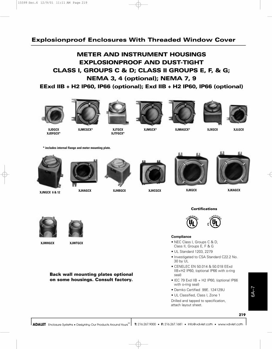
Explosionproof Enclosures With Threaded Window Cover
Compliance
• NEC Class I, Groups C & D, Class II, Groups E, F & G
• UL Standard 1203, 2279• Investigated to CSA Standard C22.2 No.
30 by UL• CENELEC EN 50.014 & 50.018 EExd
IIB+H2 IP60, (optional IP66 with o-ringseal)
• IEC 79 Exd IIB + H2 IP60, (optional IP66with o-ring seal)
• Demko Certified 99E. 124129U• UL Classified, Class I, Zone 1
METER AND INSTRUMENT HOUSINGSEXPLOSIONPROOF AND DUST-TIGHT
CLASS I, GROUPS C & D; CLASS II GROUPS E, F, & G; NEMA 3, 4 (optional); NEMA 7, 9
EExd IIB + H2 IP60, IP66 (optional); Exd IIB + H2 IP60, IP66 (optional)
XJDGCXXJDFGCX*
XJMCGCX* XJTGCXXJTFGCX*
XJMGCX* XJMAGCX* XJXGCX XJLGCX
XJHCGCXXJHBGCXXJHAGCX XJKGCX XJKAGCX
XJWHGCX XJWTGCX
XJNGCX 6 & 12
Back wall mounting plates optionalon some housings. Consult factory.
* includes internal flange and meter mounting plate.
Certifications
Drilled and tapped to specification, attach layout sheet.
15599 Sec.6 12/9/01 11:11 AM Page 219
Certifications
6A–8
220
T: 216.267.9000 • F: 216.267.1681 • [email protected] • www.adalet.comADALET Enclosure Systems • Designing Our Products Around YoursSM
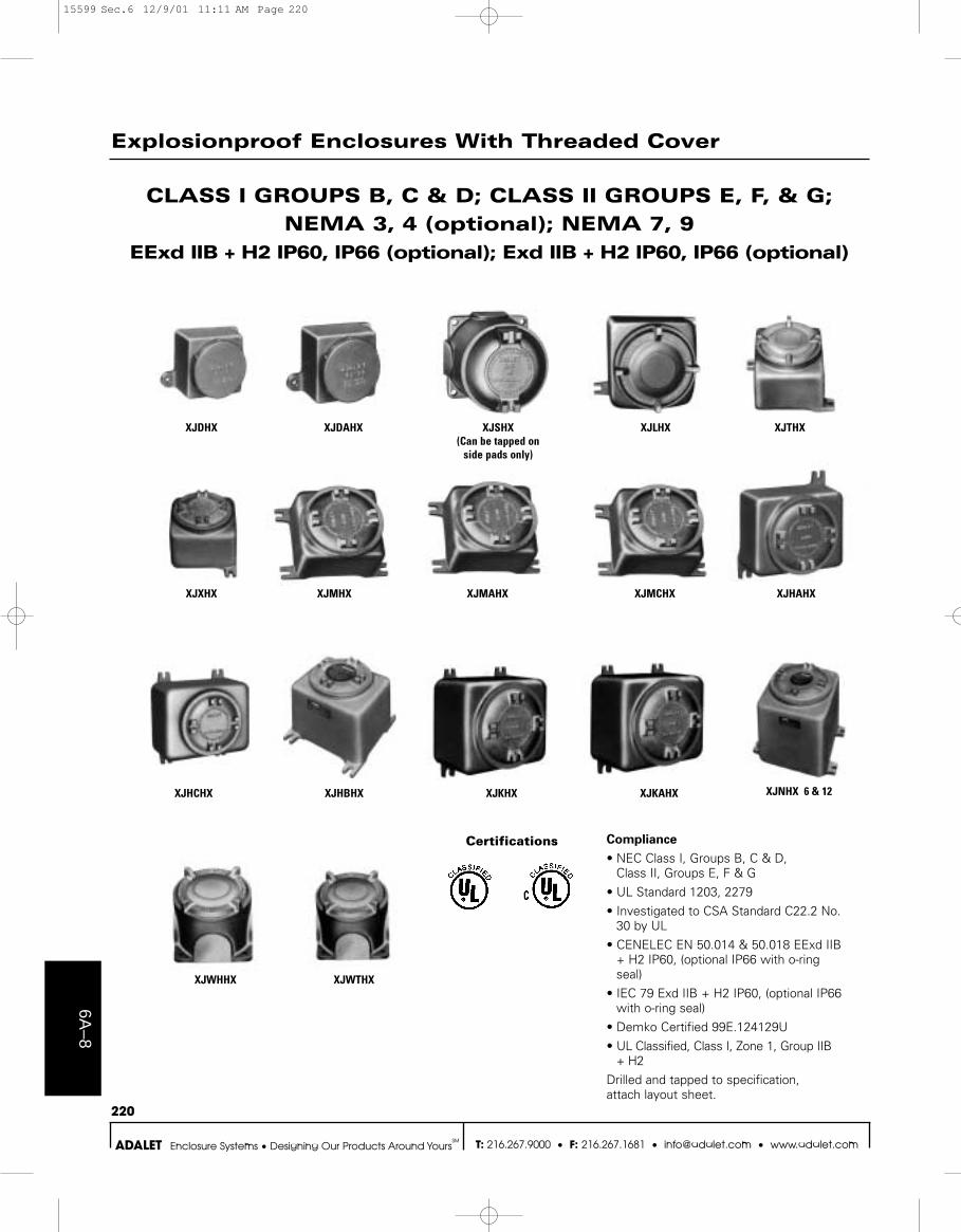
Explosionproof Enclosures With Threaded Cover
CLASS I GROUPS B, C & D; CLASS II GROUPS E, F, & G; NEMA 3, 4 (optional); NEMA 7, 9
EExd IIB + H2 IP60, IP66 (optional); Exd IIB + H2 IP60, IP66 (optional)
Compliance
• NEC Class I, Groups B, C & D, Class II, Groups E, F & G
• UL Standard 1203, 2279• Investigated to CSA Standard C22.2 No.
30 by UL• CENELEC EN 50.014 & 50.018 EExd IIB
+ H2 IP60, (optional IP66 with o-ringseal)
• IEC 79 Exd IIB + H2 IP60, (optional IP66with o-ring seal)
• Demko Certified 99E.124129U• UL Classified, Class I, Zone 1, Group IIB
+ H2Drilled and tapped to specification, attach layout sheet.
XJDHX XJDAHX XJSHX(Can be tapped on
side pads only)
XJLHX XJTHX
XJHAHXXJMCHXXJMAHXXJMHXXJXHX
XJKAHXXJKHXXJHBHXXJHCHX
XJWHHX XJWTHX
XJNHX 6 & 12
15599 Sec.6 12/9/01 11:11 AM Page 220

6A–9
221
T: 216.267.9000 • F: 216.267.1681 • [email protected] • www.adalet.comADALET Enclosure Systems • Designing Our Products Around YoursSM
Explosionproof Enclosures With Threaded Window Cover
Compliance
• NEC Class I, Groups B, C & D, Class II, Groups E, F & G
• UL Standard 1203, 2279• Investigated to CSA Standard C22.2 No. 30
by UL• CENELEC EN 50.014 & 50.018 EExd IIB +
H2 IP60, (optional IP66 with o-ring seal)• IEC 79 Exd IIB + H2 IP60, (optional IP66
w/o-ring seal)• Demko Certified 99E.124129U• UL Classified, Class I, Zone 1, Group IIB + H2
METER AND INSTRUMENT HOUSINGSEXPLOSIONPROOF AND DUST-TIGHT
CLASS I, GROUPS B, C & D; CLASS II GROUPS E, F, & G; NEMA 3, 4 (optional); NEMA 7, 9
EExd IIB + H2 IP60; IP66 (optional); Exd IIB + H2 IP66 (optional)
XJDGCHX XJDFGCHX*
XJMCGCHX* XJTGCHXXJTFGCHX*
XJMGCHX* XJMAGCHX* XJXGCHX XJLGCHX
XJHCGCHXXJHBGCHXXJHAGCHX XJKGCHX XJKAGCHX
XJWHGCHX XJWTGCHX
XJNGCHX 6 & 12
Back wall mounting plates optionalon some housings. Consult factory.
* includes internal flange and meter mounting plate.
Certifications
Drilled and tapped to specification, attach layout sheet.
15599 Sec.6 12/9/01 11:11 AM Page 221
6A–10
222
T: 216.267.9000 • F: 216.267.1681 • [email protected] • www.adalet.comADALET Enclosure Systems • Designing Our Products Around YoursSM
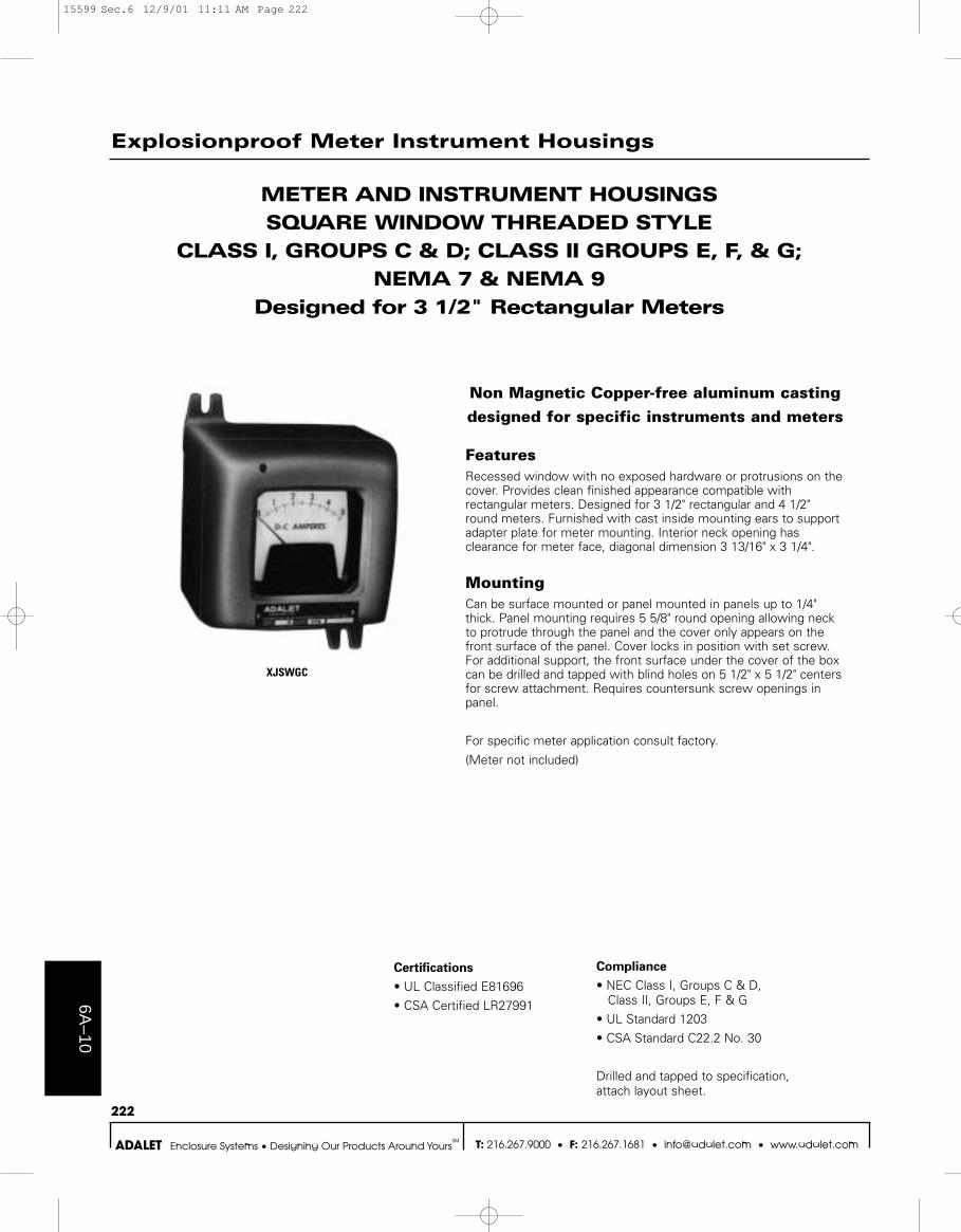
METER AND INSTRUMENT HOUSINGSSQUARE WINDOW THREADED STYLE
CLASS I, GROUPS C & D; CLASS II GROUPS E, F, & G; NEMA 7 & NEMA 9
Designed for 3 1/2" Rectangular Meters
Non Magnetic Copper-free aluminum casting
designed for specific instruments and meters
FeaturesRecessed window with no exposed hardware or protrusions on thecover. Provides clean finished appearance compatible withrectangular meters. Designed for 3 1/2" rectangular and 4 1/2"round meters. Furnished with cast inside mounting ears to supportadapter plate for meter mounting. Interior neck opening hasclearance for meter face, diagonal dimension 3 13/16" x 3 1/4".
MountingCan be surface mounted or panel mounted in panels up to 1/4"thick. Panel mounting requires 5 5/8" round opening allowing neckto protrude through the panel and the cover only appears on thefront surface of the panel. Cover locks in position with set screw.For additional support, the front surface under the cover of the boxcan be drilled and tapped with blind holes on 5 1/2" x 5 1/2" centersfor screw attachment. Requires countersunk screw openings inpanel.
For specific meter application consult factory.
(Meter not included)
Compliance
• NEC Class I, Groups C & D, Class II, Groups E, F & G
• UL Standard 1203• CSA Standard C22.2 No. 30
Drilled and tapped to specification, attach layout sheet.
Certifications
• UL Classified E81696• CSA Certified LR27991
Explosionproof Meter Instrument Housings
XJSWGC
15599 Sec.6 12/9/01 11:11 AM Page 222
6A–1
1
223
T: 216.267.9000 • F: 216.267.1681 • [email protected] • www.adalet.comADALET Enclosure Systems • Designing Our Products Around YoursSM
Explosionproof Enclosures With Threaded Cover
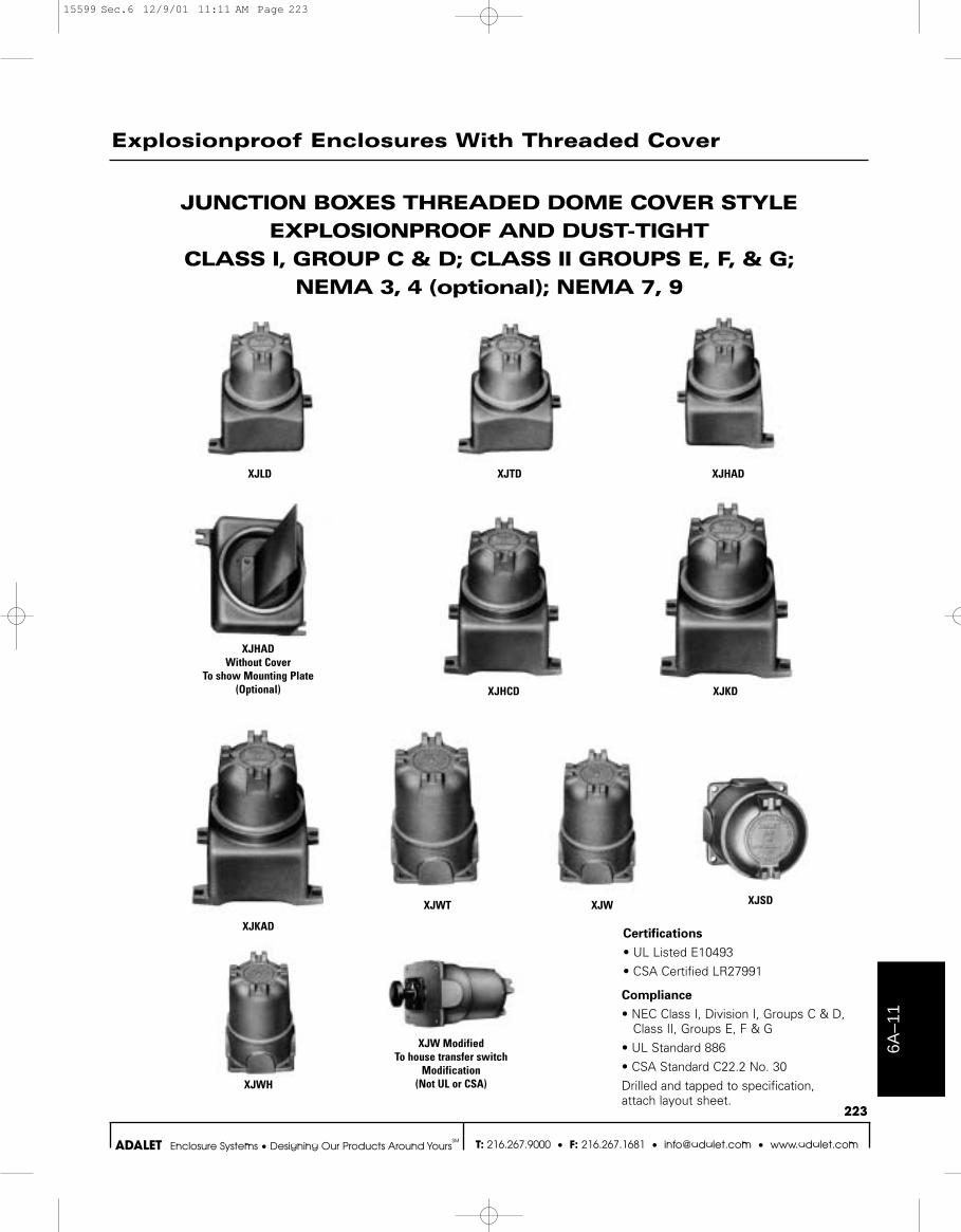
JUNCTION BOXES THREADED DOME COVER STYLEEXPLOSIONPROOF AND DUST-TIGHT
CLASS I, GROUP C & D; CLASS II GROUPS E, F, & G; NEMA 3, 4 (optional); NEMA 7, 9
Compliance
• NEC Class I, Division I, Groups C & D,Class II, Groups E, F & G
• UL Standard 886• CSA Standard C22.2 No. 30Drilled and tapped to specification, attach layout sheet.
XJLD XJTD XJHAD
XJKDXJHCD
XJWT XJW XJSD
XJKAD
XJHADWithout Cover
To show Mounting Plate(Optional)
XJW ModifiedTo house transfer switch
Modification(Not UL or CSA)XJWH
Certifications
• UL Listed E10493• CSA Certified LR27991
15599 Sec.6 12/9/01 11:11 AM Page 223
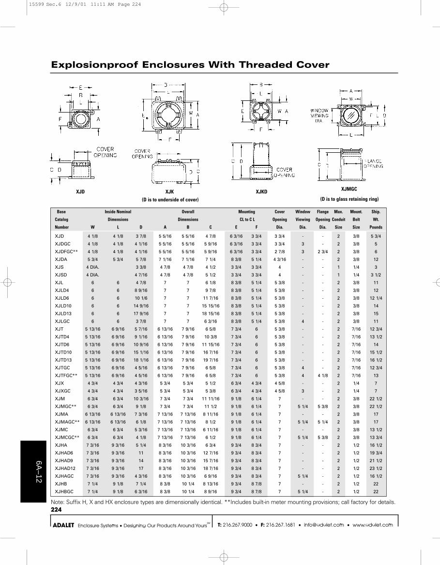
Base Inside Nominal Overall Mounting Cover Window Flange Max. Mount. Ship.
Catalog Dimensions Dimensions CL to C L Opening Viewing Opening Conduit Bolt Wt.
Number W L D A B C E F Dia. Dia. Dia. Size Size Pounds
XJD 4 1/8 4 1/8 3 7/8 5 5/16 5 5/16 4 7/8 6 3/16 3 3/4 3 3/4 - - 2 3/8 5 3/4
XJDGC 4 1/8 4 1/8 4 1/16 5 5/16 5 5/16 5 9/16 6 3/16 3 3/4 3 3/4 3 - 2 3/8 5
XJDFGC** 4 1/8 4 1/8 4 1/16 5 5/16 5 5/16 5 9/16 6 3/16 3 3/4 2 7/8 3 2 3/4 2 3/8 6
XJDA 5 3/4 5 3/4 5 7/8 7 1/16 7 1/16 7 1/4 8 3/8 5 1/4 4 3/16 - - 2 3/8 12
XJS 4 DIA. 3 3/8 4 7/8 4 7/8 4 1/2 3 3/4 3 3/4 4 - - 1 1/4 3
XJSD 4 DIA. 4 7/16 4 7/8 4 7/8 5 1/2 3 3/4 3 3/4 4 - - 1 1/4 3 1/2
XJL 6 6 4 7/8 7 7 6 1/8 8 3/8 5 1/4 5 3/8 - - 2 3/8 11
XJLD4 6 6 8 9/16 7 7 9 7/8 8 3/8 5 1/4 5 3/8 - - 2 3/8 12
XJLD6 6 6 10 1/6 7 7 11 7/16 8 3/8 5 1/4 5 3/8 - - 2 3/8 12 1/4
XJLD10 6 6 14 9/16 7 7 15 15/16 8 3/8 5 1/4 5 3/8 - - 2 3/8 14
XJLD13 6 6 17 9/16 7 7 18 15/16 8 3/8 5 1/4 5 3/8 - - 2 3/8 15
XJLGC 6 6 3 7/8 7 7 6 3/16 8 3/8 5 1/4 5 3/8 4 - 2 3/8 11
XJT 5 13/16 6 9/16 5 7/16 6 13/16 7 9/16 6 5/8 7 3/4 6 5 3/8 - - 2 7/16 12 3/4
XJTD4 5 13/16 6 9/16 9 1/16 6 13/16 7 9/16 10 3/8 7 3/4 6 5 3/8 - - 2 7/16 13 1/2
XJTD6 5 13/16 6 9/16 10 9/16 6 13/16 7 9/16 11 15/16 7 3/4 6 5 3/8 - - 2 7/16 14
XJTD10 5 13/16 6 9/16 15 1/16 6 13/16 7 9/16 16 7/16 7 3/4 6 5 3/8 - - 2 7/16 15 1/2
XJTD13 5 13/16 6 9/16 18 1/16 6 13/16 7 9/16 19 7/16 7 3/4 6 5 3/8 - - 2 7/16 16 1/2
XJTGC 5 13/16 6 9/16 4 5/16 6 13/16 7 9/16 6 5/8 7 3/4 6 5 3/8 4 - 2 7/16 12 3/4
XJTFGC** 5 13/16 6 9/16 4 5/16 6 13/16 7 9/16 6 5/8 7 3/4 6 5 3/8 4 4 1/8 2 7/16 13
XJX 4 3/4 4 3/4 4 3/16 5 3/4 5 3/4 5 1/2 6 3/4 4 3/4 4 5/8 - - 2 1/4 7
XJXGC 4 3/4 4 3/4 3 5/16 5 3/4 5 3/4 5 3/8 6 3/4 4 3/4 4 5/8 3 - 2 1/4 7
XJM 6 3/4 6 3/4 10 3/16 7 3/4 7 3/4 11 11/16 9 1/8 6 1/4 7 - - 2 3/8 22 1/2
XJMGC** 6 3/4 6 3/4 9 1/8 7 3/4 7 3/4 11 1/2 9 1/8 6 1/4 7 5 1/4 5 3/8 2 3/8 22 1/2
XJMA 6 13/16 6 13/16 7 3/16 7 13/16 7 13/16 8 11/16 9 1/8 6 1/4 7 - - 2 3/8 17
XJMAGC** 6 13/16 6 13/16 6 1/8 7 13/16 7 13/16 8 1/2 9 1/8 6 1/4 7 5 1/4 5 1/4 2 3/8 17
XJMC 6 3/4 6 3/4 5 3/16 7 13/16 7 13/16 6 11/16 9 1/8 6 1/4 7 - - 2 3/8 13 1/2
XJMCGC** 6 3/4 6 3/4 4 1/8 7 13/16 7 13/16 6 1/2 9 1/8 6 1/4 7 5 1/4 5 3/8 2 3/8 13 3/4
XJHA 7 3/16 9 3/16 5 1/4 8 3/16 10 3/16 6 3/4 9 3/4 8 3/4 7 - - 2 1/2 16 1/2
XJHAD6 7 3/16 9 3/16 11 8 3/16 10 3/16 12 7/16 9 3/4 8 3/4 7 - - 2 1/2 19 3/4
XJHAD9 7 3/16 9 3/16 14 8 3/16 10 3/16 15 7/16 9 3/4 8 3/4 7 - - 2 1/2 21 1/2
XJHAD12 7 3/16 9 3/16 17 8 3/16 10 3/16 18 7/16 9 3/4 8 3/4 7 - - 2 1/2 23 1/2
XJHAGC 7 3/16 9 3/16 4 3/16 8 3/16 10 3/16 6 9/16 9 3/4 8 3/4 7 5 1/4 - 2 1/2 16 1/2
XJHB 7 1/4 9 1/8 7 1/4 8 3/8 10 1/4 8 13/16 9 3/4 8 7/8 7 - - 2 1/2 22
XJHBGC 7 1/4 9 1/8 6 3/16 8 3/8 10 1/4 8 9/16 9 3/4 8 7/8 7 5 1/4 - 2 1/2 22
6A–12
224
T: 216.267.9000 • F: 216.267.1681 • [email protected] • www.adalet.comADALET Enclosure Systems • Designing Our Products Around YoursSM
Explosionproof Enclosures With Threaded Cover
Note: Suffix H, X and HX enclosure types are dimensionally identical. **Includes built-in meter mounting provisions; call factory for details.
XJD XJK XJKD XJMGC
(D is to underside of cover) (D is to glass retaining ring)
15599 Sec.6 12/9/01 11:11 AM Page 224

XJHC 7 3/4 10 5/16 6 3/16 8 7/8 11 7/16 7 3/4 10 1/4 7 3/4 7 - - 2 1/2 23 1/2
XJHCD6 7 3/4 10 5/16 11 15/16 8 7/8 11 7/16 13 7/16 10 1/4 7 3/4 7 - - 2 1/2 26 3/4
XJHCD9 7 3/4 10 5/16 14 15/16 8 7/8 11 7/16 16 7/16 10 1/4 7 3/4 7 - - 2 1/2 28 1/2
XJHCD12 7 3/4 10 5/16 17 15/16 8 7/8 11 7/16 19 7/16 10 1/4 7 3/4 7 - - 2 1/2 30 1/2
XJHCGC 7 3/4 10 5/16 5 1/8 8 7/8 11 7/16 7 9/16 10 1/4 7 3/4 7 5 1/4 - 2 1/2 23 1/2
XJK 9 1/2 11 1/2 7 1/4 10 3/4 12 3/4 9 1/4 12 1/4 8 9 - - 3 1/2 39 1/4
XJKD6 9 1/2 11 1/2 13 1/16 10 3/4 12 3/4 14 15/16 12 1/4 8 9 - - 3 1/2 43 3/4
XJKD12 9 1/2 11 1/2 19 1/16 10 3/4 12 3/4 20 15/16 12 1/4 8 9 - - 3 1/2 49
XJKD18 9 1/2 11 1/2 25 1/16 10 3/4 12 3/4 26 15/16 12 1/4 8 9 - - 3 1/2 54 3/4
XJKGC 9 1/2 11 1/2 6 3/16 10 3/4 12 3/4 9 1/16 12 1/4 8 9 6 11/16 - 3 1/2 39 1/4
XJKA 9 1/2 11 1/2 9 1/8 10 3/4 12 3/4 11 3/16 12 3/8 8 9 - - 3 1/2 45 3/4
XJKAD6 9 1/2 11 1/2 15 10 3/4 12 3/4 16 13/16 12 3/8 8 9 - - 3 1/2 50 1/4
XJKAD12 9 1/2 11 1/2 21 10 3/4 12 3/4 22 13/16 12 3/8 8 9 - - 3 1/2 55 1/4
XJKAD18 9 1/2 11 1/2 27 10 3/4 12 3/4 28 13/16 12 3/8 8 9 - - 3 1/2 61 1/4
XJKAGC 9 1/2 11 1/2 8 1/16 10 3/4 12 3/4 11 12 3/8 8 9 6 11/16 - 3 1/2 45 3/4
XJN6 11 1/2 12 3/4 7 7/16 13 3/8 14 5/8 9 13/16 15 3/8 9 10 11/16 - - 4 1/2 60 1/2
XJN12 11 1/2 12 3/4 13 9/16 13 9/16 14 13/16 15 15/16 15 3/8 9 10 11/16 - - 4 1/2 87 1/2
XJNGC6 11 1/2 12 3/4 6 3/16 13 3/8 14 5/8 9 7/8 15 3/8 9 10 11/16 8 - 2 1/2 60 1/2
XJNGC12 11 1/2 12 3/4 12 5/16 13 9/16 14 13/16 16 15 3/8 9 10 11/16 8 - 2 1/2 87 1/2
XJWH 6 5/8 DIA 4 3/8 7 15/16 7 15/16 5 15/16 6 3/8 6 3/8 7 - - 2 3/8 11 1/2
XJWH6 6 5/8 DIA 10 1/8 7 15/16 7 15/16 11 5/8 6 3/8 6 3/8 7 - - 2 3/8 14 3/4
XJWH9 6 5/8 DIA 13 1/8 7 15/16 7 15/16 14 5/8 6 3/8 6 3/8 7 - - 2 3/8 16 1/2
XJWH12 6 5/8 DIA 16 1/8 7 15/16 7 15/16 17 5/8 6 3/8 6 3/8 7 - - 2 3/8 18 1/2
XJWHGC 6 5/8 DIA 3 5/16 7 15/16 7 15/16 5 3/4 6 3/8 6 3/8 7 5 1/4 - 2 3/8 11 1/2
XJW3 4 7/8 DIA 5 5/16 5 11/16 5 11/16 6 7/8 4 1/2 4 1/2 4 7/8 - - 1 1/4 1/4 5
XJW5 4 7/8 DIA 7 5/16 5 11/16 5 11/16 8 11/16 4 1/2 4 1/2 4 7/8 - - 1 1/4 1/4 5 3/4
XJWT 5 3/8 DIA 3 13/16 6 3/8 6 3/8 5 1/8 5 1/8 5 1/8 5 3/8 - - 2 5/16 8
XJWT4 5 3/8 DIA 7 9/16 6 3/8 6 3/8 8 7/8 5 1/8 5 1/8 5 3/8 - - 2 5/16 9
XJWT6 5 3/8 DIA 9 1/16 6 3/8 6 3/8 10 3/8 5 1/8 5 1/8 5 3/8 - - 2 5/16 9 1/2
XJWT10 5 3/8 DIA 13 9/16 6 3/8 6 3/8 14 7/8 5 1/8 5 1/8 5 3/8 - - 2 5/16 11
XJWT13 5 3/8 DIA 16 9/16 6 3/8 6 3/8 17 7/8 5 1/8 5 1/8 5 3/8 - - 2 5/16 12
XJWTGC 5 3/8 DIA 2 15/16 6 3/8 6 3/8 5 1/8 5 1/8 5 1/8 5 3/8 4 - 2 5/16 8
XJSWGC** 5 1/4 5 1/4 4 1/16 6 1/8 6 1/8 5 5/8 7 1/8 4 3/4 5 3 3/8 x 3 3/8 3 3/4 3/4 5/16 8
XJOGC 8 8 5 1/4 9 9 7 9/16 8 8 7 5 1/4 - 2 5/16 20 1/4
6A–1
3
225
T: 216.267.9000 • F: 216.267.1681 • [email protected] • www.adalet.comADALET Enclosure Systems • Designing Our Products Around YoursSM
Explosionproof Enclosures With Threaded Cover
Base Inside Nominal Overall Mounting Cover Window Flange Max. Mount. Ship.
Catalog Dimensions Dimensions CL to CL Opening Viewing Opening Conduit Bolt Wt.
Number W L D A B C E F Dia. Dia. Dia. Size Size Pounds
Note: Suffix H, X and HX enclosure types are dimensionally identical. **Includes built-in meter mounting provisions; call factory for details.
15599 Sec.6 12/9/01 11:11 AM Page 225
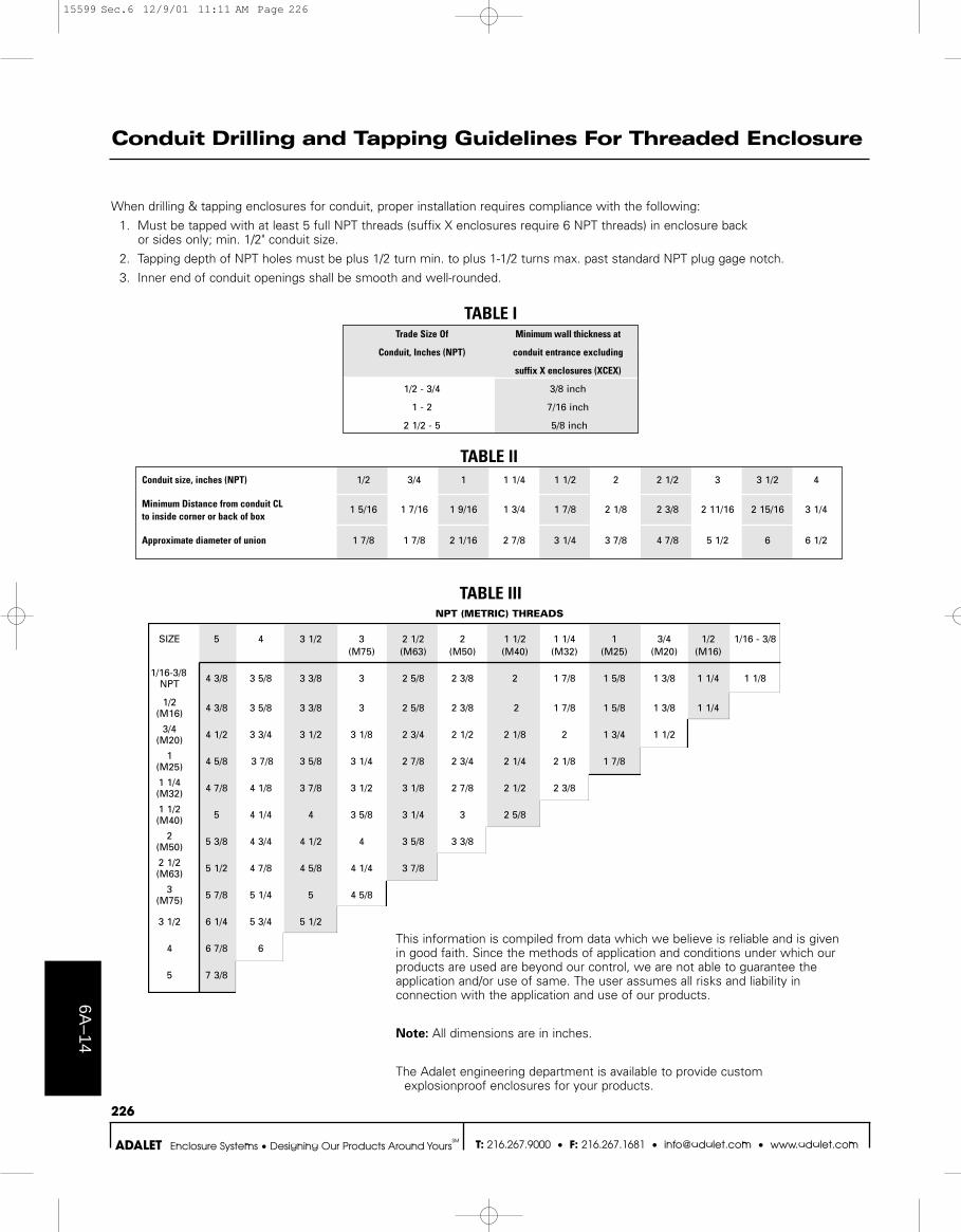
TABLE ITrade Size Of Minimum wall thickness at
Conduit, Inches (NPT) conduit entrance excluding
suffix X enclosures (XCEX)
1/2 - 3/4 3/8 inch
1 - 2 7/16 inch
2 1/2 - 5 5/8 inch
6A–14
226
T: 216.267.9000 • F: 216.267.1681 • [email protected] • www.adalet.comADALET Enclosure Systems • Designing Our Products Around YoursSM
Conduit Drilling and Tapping Guidelines For Threaded Enclosure
When drilling & tapping enclosures for conduit, proper installation requires compliance with the following:
1. Must be tapped with at least 5 full NPT threads (suffix X enclosures require 6 NPT threads) in enclosure back or sides only; min. 1/2" conduit size.
2. Tapping depth of NPT holes must be plus 1/2 turn min. to plus 1-1/2 turns max. past standard NPT plug gage notch.
3. Inner end of conduit openings shall be smooth and well-rounded.
This information is compiled from data which we believe is reliable and is givenin good faith. Since the methods of application and conditions under which ourproducts are used are beyond our control, we are not able to guarantee theapplication and/or use of same. The user assumes all risks and liability inconnection with the application and use of our products.
Note: All dimensions are in inches.
The Adalet engineering department is available to provide customexplosionproof enclosures for your products.
TABLE IIConduit size, inches (NPT) 1/2 3/4 1 1 1/4 1 1/2 2 2 1/2 3 3 1/2 4
Minimum Distance from conduit CL 1 5/16 1 7/16 1 9/16 1 3/4 1 7/8 2 1/8 2 3/8 2 11/16 2 15/16 3 1/4to inside corner or back of box
Approximate diameter of union 1 7/8 1 7/8 2 1/16 2 7/8 3 1/4 3 7/8 4 7/8 5 1/2 6 6 1/2
NPT (METRIC) THREADS
SIZE 5 4 3 1/2 3 2 1/2 2 1 1/2 1 1/4 1 3/4 1/2 1/16 - 3/8(M75) (M63) (M50) (M40) (M32) (M25) (M20) (M16)
1/16-3/8 4 3/8 3 5/8 3 3/8 3 2 5/8 2 3/8 2 1 7/8 1 5/8 1 3/8 1 1/4 1 1/8NPT
1/2 4 3/8 3 5/8 3 3/8 3 2 5/8 2 3/8 2 1 7/8 1 5/8 1 3/8 1 1/4(M16)
3/4 4 1/2 3 3/4 3 1/2 3 1/8 2 3/4 2 1/2 2 1/8 2 1 3/4 1 1/2(M20)
1 4 5/8 3 7/8 3 5/8 3 1/4 2 7/8 2 3/4 2 1/4 2 1/8 1 7/8(M25)
1 1/4 4 7/8 4 1/8 3 7/8 3 1/2 3 1/8 2 7/8 2 1/2 2 3/8(M32)
1 1/2 5 4 1/4 4 3 5/8 3 1/4 3 2 5/8(M40)
2 5 3/8 4 3/4 4 1/2 4 3 5/8 3 3/8(M50)
2 1/2 5 1/2 4 7/8 4 5/8 4 1/4 3 7/8(M63)
3 5 7/8 5 1/4 5 4 5/8(M75)
3 1/2 6 1/4 5 3/4 5 1/2
4 6 7/8 6
5 7 3/8
TABLE III
15599 Sec.6 12/9/01 11:11 AM Page 226
6A–1
5
227
T: 216.267.9000 • F: 216.267.1681 • [email protected] • www.adalet.comADALET Enclosure Systems • Designing Our Products Around YoursSM
Explosionproof Enclosures With Threaded Cover
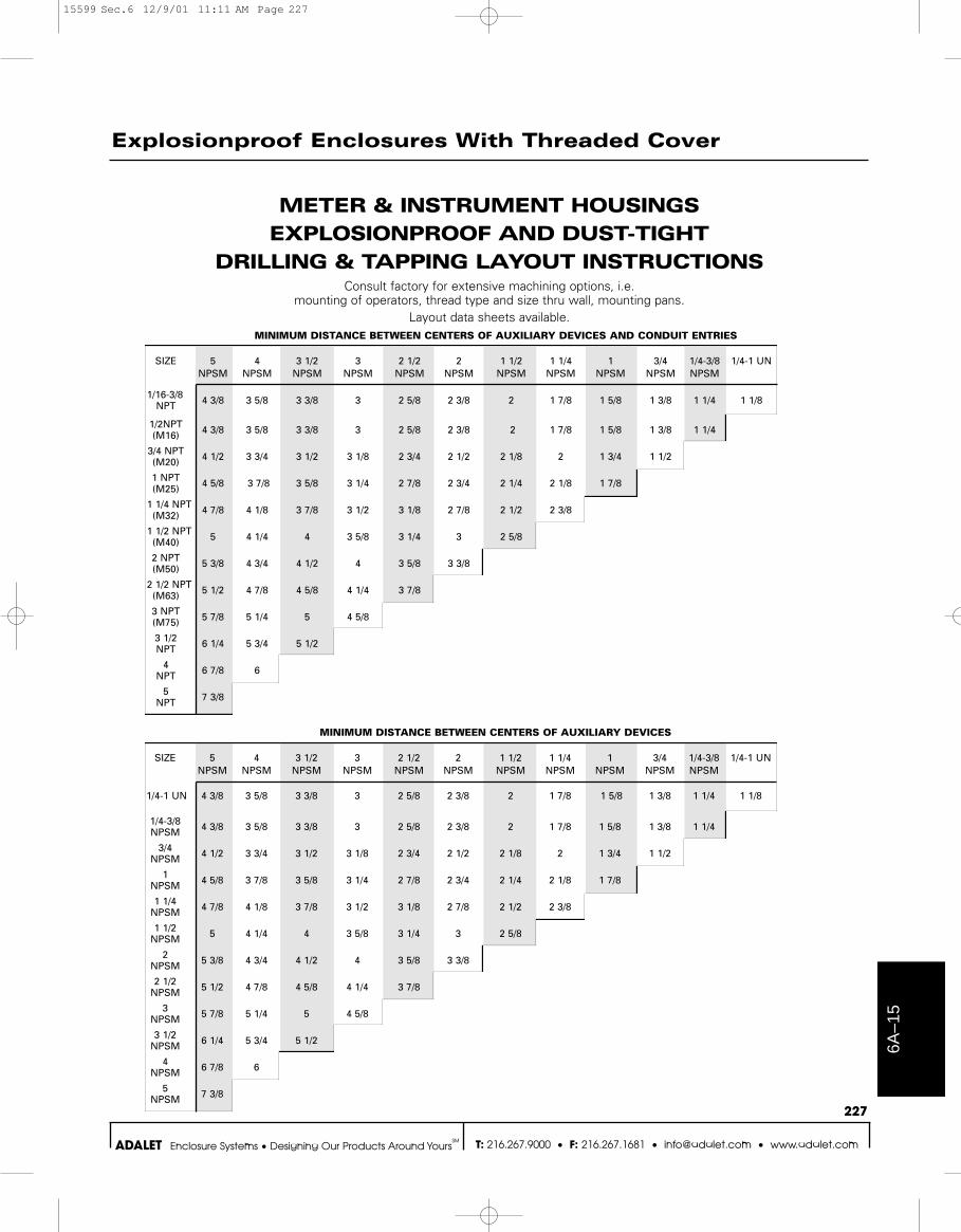
METER & INSTRUMENT HOUSINGSEXPLOSIONPROOF AND DUST-TIGHT
DRILLING & TAPPING LAYOUT INSTRUCTIONSConsult factory for extensive machining options, i.e.
mounting of operators, thread type and size thru wall, mounting pans.Layout data sheets available.
MINIMUM DISTANCE BETWEEN CENTERS OF AUXILIARY DEVICES
SIZE 5 4 3 1/2 3 2 1/2 2 1 1/2 1 1/4 1 3/4 1/4-3/8 1/4-1 UNNPSM NPSM NPSM NPSM NPSM NPSM NPSM NPSM NPSM NPSM NPSM
1/4-1 UN 4 3/8 3 5/8 3 3/8 3 2 5/8 2 3/8 2 1 7/8 1 5/8 1 3/8 1 1/4 1 1/8
1/4-3/8 4 3/8 3 5/8 3 3/8 3 2 5/8 2 3/8 2 1 7/8 1 5/8 1 3/8 1 1/4NPSM
3/4 4 1/2 3 3/4 3 1/2 3 1/8 2 3/4 2 1/2 2 1/8 2 1 3/4 1 1/2NPSM
1 4 5/8 3 7/8 3 5/8 3 1/4 2 7/8 2 3/4 2 1/4 2 1/8 1 7/8NPSM
1 1/4 4 7/8 4 1/8 3 7/8 3 1/2 3 1/8 2 7/8 2 1/2 2 3/8NPSM
1 1/2 5 4 1/4 4 3 5/8 3 1/4 3 2 5/8NPSM
2 5 3/8 4 3/4 4 1/2 4 3 5/8 3 3/8NPSM
2 1/2 5 1/2 4 7/8 4 5/8 4 1/4 3 7/8NPSM
3 5 7/8 5 1/4 5 4 5/8NPSM
3 1/2 6 1/4 5 3/4 5 1/2NPSM
4 6 7/8 6NPSM
5 7 3/8NPSM
MINIMUM DISTANCE BETWEEN CENTERS OF AUXILIARY DEVICES AND CONDUIT ENTRIES
SIZE 5 4 3 1/2 3 2 1/2 2 1 1/2 1 1/4 1 3/4 1/4-3/8 1/4-1 UNNPSM NPSM NPSM NPSM NPSM NPSM NPSM NPSM NPSM NPSM NPSM
1/16-3/8 4 3/8 3 5/8 3 3/8 3 2 5/8 2 3/8 2 1 7/8 1 5/8 1 3/8 1 1/4 1 1/8NPT
1/2NPT 4 3/8 3 5/8 3 3/8 3 2 5/8 2 3/8 2 1 7/8 1 5/8 1 3/8 1 1/4(M16)
3/4 NPT 4 1/2 3 3/4 3 1/2 3 1/8 2 3/4 2 1/2 2 1/8 2 1 3/4 1 1/2(M20)
1 NPT 4 5/8 3 7/8 3 5/8 3 1/4 2 7/8 2 3/4 2 1/4 2 1/8 1 7/8(M25)
1 1/4 NPT 4 7/8 4 1/8 3 7/8 3 1/2 3 1/8 2 7/8 2 1/2 2 3/8(M32)
1 1/2 NPT 5 4 1/4 4 3 5/8 3 1/4 3 2 5/8(M40)
2 NPT 5 3/8 4 3/4 4 1/2 4 3 5/8 3 3/8(M50)
2 1/2 NPT 5 1/2 4 7/8 4 5/8 4 1/4 3 7/8(M63)
3 NPT 5 7/8 5 1/4 5 4 5/8(M75)
3 1/2 6 1/4 5 3/4 5 1/2NPT
4 6 7/8 6NPT
5 7 3/8NPT
15599 Sec.6 12/9/01 11:11 AM Page 227