Explosion Protection - Endress+Hauser Portal are three prerequisites for an explosion: a...
36
Products Solutions Services Explosion Protection Explosion Protection Guidelines and General Principles © Light&Magic - shutterstock.com
-
Upload
trinhhuong -
Category
Documents
-
view
217 -
download
0
Transcript of Explosion Protection - Endress+Hauser Portal are three prerequisites for an explosion: a...

Products Solutions ServicesEx
plos
ion
Prot
ectio
n
Explosion ProtectionGuidelines and General Principles
© L
ight
&Mag
ic -
shut
ters
tock
.com

© Ir
is S
peth
- Pa
nthe
rMed
iaExplosion protection2

3Foreword
In many industry sectors, combustible and potentially explosive atmospheres in the form of gases, vapors, mists or dusts are a present concern. The coal mining, chemical and petrochemical sectors are of particular concern, but the food industry, mill operation, wastewater and biogas production sectors are also affected. These combustible substances can form a potentially explosive atmosphere when mixed with oxygen. The explosions occurring when this atmosphere is ignited can result in severe personal injury and/or damage to property. To prevent the risk of explosion, most industrialized nations have developed protective precautions in the form of laws, regulations and standards so as to achieve a high level of safety.
Based on the frequency and duration of the occurrence of potentially explosive atmosphere, the affected sectors, plants or plant sections are classified into zones of different degrees of exposure. The operators of these facilities are required to prevent explosion hazards via protective measures in potentially explosive atmospheres.
Foreword
There are three prerequisites for an explosion: a combus-tible gas or dust, oxygen and a source of ignition. Primary explosion prevention can be achieved by, for example, inerting the gas atmosphere. On the other hand, secondary explosion prevention consists of avoiding sources of ignition. Manufacturers of devices and protection systems must therefore develop and design their devices and systems so that they present no source of ignition – neither in normal opperation nor in consideration of foreseeable faults. Design-based explosion prevention limits the effects of an explosion to a tolerable level.
This brochure provides an introduction to and overview of explosion prevention, focusing on device and protection system requirements for use in potentially explosive atmospheres. Note that the legal and normative regulations are subject to ongoing revisions and adaptations to new technical developments. The information contained in this brochure therefore corresponds to the current status at the time this document was created.
Table of contents
1. Generalprinciplesanddefinitions ..................................................................................................................................5
2. European Community – guidelines .............................................................................................................................. 10
3. North American region – guidelines ........................................................................................................................... 24
4. IECEx program ................................................................................................................................................................ 28
5. Glossary .......................................................................................................................................................................... 30
Explosive atmosphere
Combustible substance
Explosion
Air / oxygen
Ignition source
Secondary explosion prevention
Preventing the ignition of a hazardous, potentially explosive atmosphere
Primary explosion protection
Preventing the formation of a hazardous, potentially explosive atmosphere
Design-related explosion prevention
Limiting the effect of an explosion to a tolerable level
321
Explosion protection4
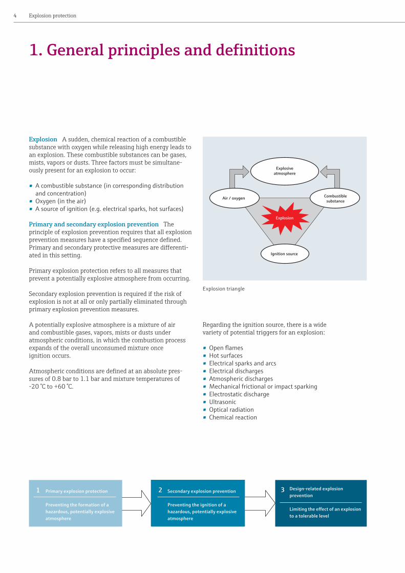
Explosion A sudden, chemical reaction of a combustible substance with oxygen while releasing high energy leads to an explosion. These combustible substances can be gases, mists, vapors or dusts. Three factors must be simultane-ously present for an explosion to occur:
•A combustible substance (in corresponding distribution and concentration)
•Oxygen (in the air) •A source of ignition (e.g. electrical sparks, hot surfaces)
Primary and secondary explosion prevention The principle of explosion prevention requires that all explosion prevention measures have a specified sequence defined. Primary and secondary protective measures are differenti-ated in this setting.
Primary explosion protection refers to all measures that prevent a potentially explosive atmosphere from occurring.
Secondary explosion prevention is required if the risk of explosion is not at all or only partially eliminated through primary explosion prevention measures.
A potentially explosive atmosphere is a mixture of air and combustible gases, vapors, mists or dusts under atmospheric conditions, in which the combustion process expands of the overall unconsumed mixture once ignition occurs.
Atmospheric conditions are defined at an absolute pres-sures of 0.8 bar to 1.1 bar and mixture temperatures of -20 °C to +60 °C.
1. General principles and definitions
Explosion triangle
Regarding the ignition source, there is a wide variety of potential triggers for an explosion:
•Open flames•Hot surfaces• Electrical sparks and arcs• Electrical discharges•Atmospheric discharges•Mechanical frictional or impact sparking• Electrostatic discharge•Ultrasonic•Optical radiation• Chemical reaction

0 vol% 100 vol%LEL
UEL
Lower explosion limit
Upper explosion limit
Lean mixture
Rich mixture
Potentially explosive atmosphere
5General principles and definitions
Classification of flammable gases
Toassesstechnicalsafety,definedcharacteristicquantities of combustible substances are necessary
Explosion limits A potentially explosive atmosphere forms from combustible substances if they are in a defined concentration range (see image). If the concentrations are too low (lean mixture) or too high (rich mixture), then no explosion occurs, but rather a slow burning process, if any at all. The mixture only reacts explosively when ignited in the range between the upper and lower explosion limit. The explosion limits are dependent upon ambient pressure and the oxygen content of the air. Depending on the speed of the elapsing burning process, it may be designated as a deflagration, explosion or detonation. An potentially explosive atmosphere exists if ignition presents a danger to persons or property. A potentially explosive atmosphere, even one with low volume, can lead to hazardous explo-sions in a closed room.
Substance designation
Lower explosion limit [vol. %]
Upper explosion limit [vol. %]
Acetylene 2.3 78.0Ethylene 2.3 32.4Gasoline 0.6 8.0Benzene 1.2 8.0Natural gas 4.0 13.0Heating oil/diesel 0.6 6.5Methane 4.4 16.5Propane 1.7 10.9Carbon disulfide 0.6 60.0Coal gas 4.0 30.0Hydrogen 4.0 77.0
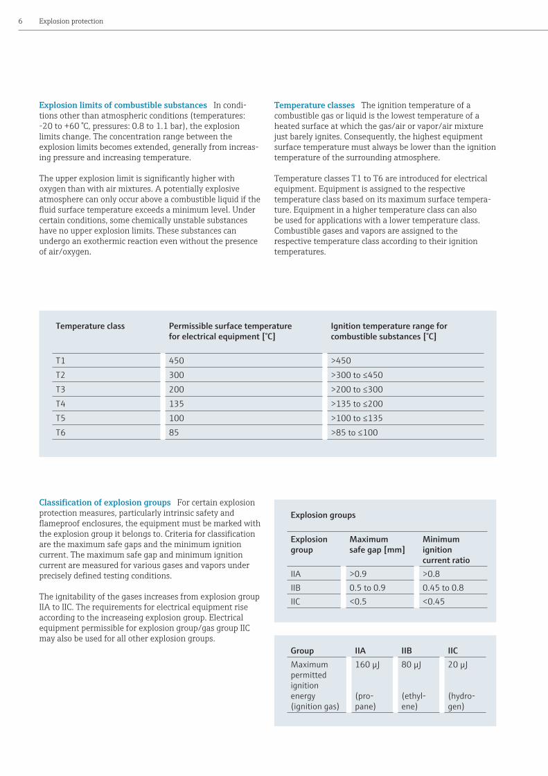
Classificationofexplosiongroups For certain explosion protection measures, particularly intrinsic safety and flameproof enclosures, the equipment must be marked with the explosion group it belongs to. Criteria for classification are the maximum safe gaps and the minimum ignition current. The maximum safe gap and minimum ignition current are measured for various gases and vapors under precisely defined testing conditions.
The ignitability of the gases increases from explosion group IIA to IIC. The requirements for electrical equipment rise according to the increaseing explosion group. Electrical equipment permissible for explosion group/gas group IIC may also be used for all other explosion groups.
Explosion protection6
Temperature class
Permissible surface temperature for electrical equipment [°C]
Ignition temperature range for combustible substances [°C]
T1 450 >450T2 300 >300 to ≤450T3 200 >200 to ≤300T4 135 >135 to ≤200T5 100 >100 to ≤135T6 85 >85 to ≤100
Explosion groups
Explosion group
Maximum safe gap [mm]
Minimum ignition current ratio
IIA >0.9 >0.8IIB 0.5 to 0.9 0.45 to 0.8IIC <0.5 <0.45
Group IIA IIB IICMaximum permitted ignition energy (ignition gas)
160 µJ (pro-pane)
80 µJ (ethyl-ene)
20 µJ (hydro-gen)
Explosion limits of combustible substances In condi-tions other than atmospheric conditions (temperatures: -20 to +60 °C, pressures: 0.8 to 1.1 bar), the explosion limits change. The concentration range between the explosion limits becomes extended, generally from increas-ing pressure and increasing temperature.
The upper explosion limit is significantly higher with oxygen than with air mixtures. A potentially explosive atmosphere can only occur above a combustible liquid if the fluid surface temperature exceeds a minimum level. Under certain conditions, some chemically unstable substances have no upper explosion limits. These substances can undergo an exothermic reaction even without the presence of air/oxygen.
Temperature classes The ignition temperature of a combustible gas or liquid is the lowest temperature of a heated surface at which the gas/air or vapor/air mixture just barely ignites. Consequently, the highest equipment surface temperature must always be lower than the ignition temperature of the surrounding atmosphere.
Temperature classes T1 to T6 are introduced for electrical equipment. Equipment is assigned to the respective temperature class based on its maximum surface tempera-ture. Equipment in a higher temperature class can also be used for applications with a lower temperature class. Combustible gases and vapors are assigned to the respective temperature class according to their ignition temperatures.

Minimum ignition energy (mJ)
1000
100
10
1
0.1
0.01Gases Dusts Typical ignition sources
Welding sparks, impact sparks
Grinding sparks (cut-off grinder)
Electrostatic discharges,
impact sparks
7General principles and definitions
Solid substances in crushed form – e.g. in the form of dust or fibers – are frequently present in industrial sectors, e.g. in chemical plants, the food industry or flour mills. Dust is a finely dispersed solid below a particle size of approx. 500 µm. If dust layers with small particle size are dispersed, a risk of explosion is present. The risk of explosion grows with decreasing particle size. Frequently, explosions result from dispersed dust layers that contain their own ignition source. A dust layer of less than 1 mm distributed uniform-ly on the ground is sufficient to fill a room with normal ceiling height with a potentially explosive dust/air mixture when the dust is uniformly dispersed.
Safety relevant data include parameters for dispersed dusts such as the minimum ignition energy and the ignition temperature, whereas the glow temperature is a character-istic property for dust layers.
Gases, vapors and dusts
Minimum ignition energy in mJ (millijoules)
Carbon disulfide 0.009Hydrogen 0.017Acetylene 0.019Benzene 0.20Ethanol 0.28Methane 0.29Wood flour 20 – 60Sugar 40Lignite 80Ammonia 680
Minimum ignition energy for various materials
Minimum ignition energy A specific amount of energy has to be applied to ignite a potentially explosive atmo-sphere. The minimum ignition energy is the least possible amount of converted energy (e.g. discharge of a capacitor) needed to ignite the corresponding combustible mixture. The minimum ignition energy is between approximately 20 µJ for hydrogen up to a few joules for certain dusts.

© B
ASF
- Pr
ess P
hoto
Explosion protection8
Classification of flammable dusts
Ignition temperature [Tignition] The lowest temperature of a hot surface [Tmax(1)], detected under specified test conditions, at which the most ignitable mixture of dust with air (dust cloud) ignites.
Glow temperature [Tglow] The glow temperature is the lowest temperature of a hot surface, detected under specified test conditions, at which a dust layer with 5 mm thickness starts to glow.
If dust layers thicker than 5 mm can form on equipment, the maximum permitted surface temperature [TMax(2)] must be reduced accordingly. The maximum permitted surface temperature can be reduced according to the chart per EN 60079-0.
Maximum permitted surface temperature (1): Tmax(1) = 2/3 Tignition
Maximum permitted surface temperature (2): Tmax(2) = Tglow - 75 K
Example:
Minimum ignition temperature: 330 °CMinimum glow temperature: 300 °C• Maximum permitted surface temperature for
dust clouds Tmax(1) = 2/3 x 330 °C = 220 °C• Maximum permitted surface temperature for
dust layers (5 mm thickness) Tmax(2) = 300 °C – 75 K = 225 °C
• Permitted surface temperature = 220 °C In this case, equipment used must have a max. surface temperature of < 220 °C in case of error.

9General principles and definitions
Decrease of the maximum permitted surface temperature in case of increasing dust layer thickness (chart per IEC/EN 60079-14)
Thermal insulation increases for thicker dust layers, with the result that the dust layer can glow even at low housing temperatures. Therefore, ensure that the equipment surface temperature is reduced. This surface temperature has to be determined according to the graph above for dust layers between 5 mm and 50 mm. These curves take a typical temperature reduction of 75 K into account.
°C
400
300
200
100
00
10 20 30 40 50 mmLayer thickness
Glow temperature at 5 mm layer thickness
400 °C ≤ T₅ mm
320 °C ≤ T₅ mm < ₄₀₀ °C
250 °C ≤ T₅ mm < ₃₂₀ °C
Max
. per
mitt
ed e
quip
men
t su
rfac
e te
mpe
ratu
re
If the layer thickness is greater than 50 mm, or if dust completely covers the equipment, the glow temperature must be measured via laboratory testing. This also applies for layer thicknesses >5 mm, if the glow temperature at 5 mm layer thickness is <250 °C. Laboratory tests are also necessary if the device is completely submersed in combustible dust.

© B
ASF
- Pr
ess P
hoto
Explosion protection10
2. European Community
Explosion protection in Europe In the European Union, explosion protection is regulated per ATEX Directives 94/9/EC and 1999/92/EC. Compliance with the essential health and safety requirements of ATEX Directive 94/9/EC regarding explosion-protected equipment must be docu-mented in the manufacturer's EC-declaration of conformity for the respective equipment. It is presumed that the basic safety requirements are fulfilled when applying the relevant harmonized EU standards (presumption principle). This directive's scope of validity extends to potentially explosive gas and dust atmospheres in underground and surface mining. For the first time, nonelectrical explosion preven-tion is also addressed here. Regulations for occupational safety in potentially explosive atmospheres are set forth in the second ATEX Directive, 1999/92/EC.
This directive contains only the minimum requirements. When transposing these into national laws, individual states can supplement further-reaching regulations. Per Directive 1999/92/EC, the user has to assess the explosion risks of a plant, classify the hazardous area into zones and document all measures taken to ensure employee safety in the explosion protection document.
Explosion protection document in accordance with BetrSichV and ATEX Directive 1999/92/EC An explosion protection document must be created that at least contains information concerning • the risk assessment• the protective measures taken • the zone classification• compliance with the minimum requirements according
to Appendix 4. These are divided into organizational measures (instructing the employees, etc.) and into technical measures (explosion protection measures).

11European Community
Zone classification
Gases, vapors
Zone 0 A place in which a potentially explosive atmosphere consisting of a mixture with air of flammable substances in the form of gas, vapour or mist is present continuously, for long periods or frequently.
Zone 1 A place in which a potentially explosive atmosphere consisting of a mixture with air of flammable substances in the form of gas, vapor or mist is likely to occur in normal operation occasionally.
Zone 2 A place in which a potentially explosive atmosphere consisting of a mixture with air of flammable substances in the form of gas, vapor or mist is not likely to occur in normal operation but, if it does occur, will persist for only a short period.
Dusts Zone 20 A place in which a potentially explosive atmosphere in the form of a cloud of combustible dust in the air is present continuously, for long periods or frequently.
Zone 21 A place in which a potentially explosive atmosphere in the form of a cloud of combustible dust in the air is likely to occur in normal operation occasionally.
Zone 22 A place in which a potentially explosive atmosphere in the form of a cloud of combustible dust in the air is not likely to occur in normal operation but, if it does occur, will persist for only a short period.
Zone 0 Area with gas above the fluid surface
Zone 1 Immediate vicinity around the open vent (3 m)
Zone 2 Area outside of Zone 1 (3 m)
Zone 20 Filling hopper of a bag-emptying station
Zone 21 Immediate vicinity (radius of 1 m) around the open feed opening
Zone 22 Area outside of Zone 21 due to settling dust
Zone 2Zone 1
Zone 0
Potentially explosive atmospheres are classified into zones to facilitate the selection of appropriate equipment and to design proper electrical installations. The zone classifica-tion reflects the probability of a potentially explosive
Zone 22
Zone 21Zone 20
atmosphere occurring. Specifications for zone classification can be found in IEC EN 60079-10 for areas with potentially explosive gas and in IEC EN 61241-10 for areas with combustible dust.
Filling hopper
Work level
Conveyor

Explosion protection12
Types of protection
The types of explosion protection define constructive and electrical circuit technology measures for equipment for use in potentially explosive atmospheres. These measures prevent spark formation or hot surfaces from igniting a surrounding potentially explosive atmosphere.
Electrical equipment for explosive gas atmospheresAbbreviations IEC EN DIN
General requirements 60079-0Flameproof encapsulation d 60079-1Pressurized p 60079-2Powder filling q 60079-5Oil-immersion o 60079-6Increased safety e 60079-7Intrinsic safety i 60079-11Explosion protection measures n 60079-15Encapsulation m 60079-18Intrinsically safe systems 60079-25Electrical equipment Category 1G 60079-26Intrinsically safe fieldbus systems 60079-28
The measures according to IEC or EN apply for dust explosion protection
Electrical equipment for areas with combustible dustAbbreviations IEC EN DIN
General requirements 60079-0Protection by enclosure t 60079-31Pressurized p 60079-2Intrinsic safety i 60079-11Encapsulation m 60079-18
Corresponding protection principles have been defined in IEC 60079 et. seq. for electrical equipment in an area where gas can explode.

© b
adah
os -
Foto
lia.co
m
13European Community
Typeofprotection“IntrinsicSafety”(Ex “i”)An intrinsically safe circuit is a circuit in which neither a spark nor a thermal effect can cause a certain potentially explosive atmosphere to ignite.
Charakteristics of the type of protection “Intrinsic Safety” is based on the principle of limiting the current and voltage in a circuit. The energy of the circuit which could be capable of igniting a potentially explosive atmosphere is limited so that neither sparking nor impermissible heating of the electrical components can ignite the surrounding potentially explosive atmosphere.
“Intrinsic Safety” is applied particularly in measurement and control technology, since no high currents, voltages and outputs are required there.
Intrinsically safe electrical equipment Electrical equipment in which all circuits are intrinsically safe.
Associated electrical equipment Electrical equipment that includes both intrinsically safe and non-intrinsically safe circuits, and that is constructed so that the non-intrin-sically safe circuits cannot impair the intrinsically safe circuits.
An essential aspect of “Intrinsic Safety” is fault analysis with regard to compliance of the limits on voltage, current and output. Intrinsically safe electrical equipment and intrinsically safe parts of associated equipment are classi-fied into protection levels “ia”, “ib” or “ic” with respect to this fault analysis. Depending on the approval for the gas Ex area (EPL Gx) or dust Ex area (EPL Dx), equipment with protection level “ia” can be used in Zone 0 or 20. Protection level “ib” is for use in Zone 1 or 21, and protection level “ic” is for Zone 2 or 22.
An important protective measure for intrinsically safe circuits is the safe isolation of intrinsically safe circuits from non-intrinsically safe circuits. For use in Zone 0, galvanic isolation between intrinsically safe and non-intrinsically safe circuits is recommended.
Interconnecting of intrinsically safe circuits When interconnecting equipment with intrinsically safe circuits, the user must provide a verification of intrinsic safety showing that the “intrinsic safety” has not been impaired. Interconnecting involves the following cases:• two intrinsically safe pieces of equipment• one intrinsically safe piece of equipment with one
associated intrinsically safe piece of equipment•more than one associated or active piece of equipment
The rules for interconnecting are provided in the IEC/EN 60079-14 installation design rules. According to this, the safety-related characteristic values of the equipment's input and output parameters have to be compared in order to verify whether the interconnection of multiple pieces of equipment with intrinsically safe circuits satisfy the requirements of intrinsic safety. Interconnection is permit-ted only if all necessary conditions have been satisfied. Cable parameters also have to be taken into account which, together with the equipment parameters, influence the permitted cable lengths. Here, the planner has to create a system description, what is called the “intrinsic safety verification”, in which the individual pieces of electrical equipment are specified with the characteristic values, including the characteristic values of the connecting cables.
Ex „i“
Explosion protection14
Intrinsically safe electrical equipment and intrinsically safe parts of associated equipment are classified in categories
Power supplies and isolators between the intrinsically safe and non-intrinsically safe circuits of the apparatus provide
Category of intrinsically safe equipment
Description Installation of the equipment
Gas/dust Gas(EPL Gx)
Dust(EPL Dx)
ia Intrinsically safe electrical equipment is not allowed to cause an ignition•During normal operation• If a single countable error occurs• If two countable errors occur in the equipment
Zone 0 Zone 20
ib Intrinsically safe electrical equipment is not allowed to cause an ignition•During normal operation• If a single error occurs in the equipment
Zone 1 Zone 21
ic Intrinsically safe electrical equipment is not allowed to cause an ignition during normal operation
Zone 2 Zone 22
Type of protection “increased safety” Ex “e” This type of protection applies for apparatus that does not normally generate sparks or electric arcs, does not take on hazardous temperatures and for which the power supply voltage does not exceed 1 kV.
Typeofprotection“flameproofenclosures”Ex“d” The spread of an explosion is prevented using the “flameproof encapsulation” explosion protection type. The degree of protection is based on design engineering measures. Penetration of gases is not prevented. In case of an ignition within the enclosure, the enclosure will withstand the explosive pressure and the ignition is not transmitted to the outside. There are no temperatures higher than permitted values on the housing surface.
Application and combination of types of protection Ex “d” and Ex “e”“Flameproof enclosures”, usually together with the type of protection “increased safety”, is the important explosion protection type for measuring devices with high energy consumption. A connection housing with increased safety can be provided with a customer-side Ex e cable entry to make the electrical installation easier for devices with flameproof encapsulation. The flameproof cable bushing in the Ex d electronics compartment is already installed at the factory.
Type of protection “encapsulation” Ex “m” The principle of encapsulation is to enclose potential sources of ignition in electrical apparatus using a suitable sealing compound. This prevents ignition of an explosive atmosphere.
Ex “e”
Ex “d”
Ex “d/e”
Ex d
Ex e
Ex “m”
(safety levels). The safety levels depend on the safety requirements for designing the equipment.
the necessary voltage and current limitation for use in potentially explosive atmospheres.

15European Community
Non-electrical explosion protection With the release of Directive 94/9/EC, the EN 13463 standard series (will be EN 80079) in Europe also defined constructional regula-tions for non-electrical equipment. Some protection
National implementation of Directive 1999/92/EC The directive was adopted into German law by the German Ordinance on Industrial Safety and Health (BetrSichV). The German Ordinance on Industrial Safety and Health (BetrSichV), “Ordinance concerning the protection of safety and health in the provision of work equipment and its use at work, concerning safety when operating installations subject to monitoring and concerning the organization of industrial safety and health at work”, contains detailed regulations on the operation of Ex installations. One of the regulations in the BetrSichV is that equipment and protec-tive systems in potentially explosive atmospheres have to be selected in accordance with Directive 94/9/EC. They must be provided with the required equipment marking for use in the respective zone.
Two groups of equipment are distinguished based on ATEX Directive 94/9/EC:
Non-electrical equipment for use in potentially explosive atmospheresAbbreviations EN
Basic method and requirements 13463-1Protection by flow restricting enclosure fr 13463-2Protection by flameproof enclosure d 13463-3Protection by constructional safety c 13463-5Protection by control of ignition source b 13463-6Protection by liquid immersion k 13463-8
Equip-ment group
Equipment
I Electrical equipment for mines endangered by firedamp
II Electrical equipment for potentially explosive gas and/or dust atmospheres
In the IEC standards and the related EN standards for the dust Ex area Group III was introduced. Marking example: II 1D Ex ta IIIC
Type of protection Ex “n” These explosion protection measures can be used for Category 3G devices. Multiple measures are possible for this purpose:•Non-sparking apparatus ........................Ex “nA” marking (replaced by Ex ec in future)•Apparatus with enclosed break .............Ex “nC” marking • Limited power apparatus ....................... Ex “nL” marking (replaced by Ex ic)• Restricted breathing apparatus .............Ex “nR” marking• Simplified pressurized apparatus ..........Ex “nP” markingThese protective measures are suitable for use in Zone 2 hazardous areas. The Ex nL measure has already been converted to the Ex ic type of explosion protec-tion and is no longer permitted for placing products into the market in Europe after May 2013. Ex nA will soon be converted to the Ex ec type of explosion protection.
principles for electrical equipment have been taken over. This involved adaptations to take into account the special requirements for the non-electrical equipment.

Explosion protection16
Equipment groups describe the degree of protection and range of application for equipment (in accordance with ATEX Directive 94/9/EC). Equipment that has a potential source of ignition which can cause an explosion must undergo an assessment of explosion risks. Based on this, measures must be undertaken corresponding to the basic safety requirements in order to exclude an ignition risk from this equipment. Equipment in Equipment Group I is classified into two categories and equipment in Equipment Group II into three categories (Category 1, 2 and 3), each with a different safety level. The required protective measures depend on the required safety level in each case.
Equipment for use in areas with potentially explosive dust atmospheres were classified in Equipment Group III. Equipment Group III introduced via the IEC standardization is now a new addition in the marking of dust Ex equipment.
Equipment Group I Equipment Group I applies to equip-ment intended for use in underground parts of mines, and in those parts of surface installations of such mines, liable to be endangered by firedamp and/or combustible dust (in accordance with ATEX Directive 94/9/EC). For electrical equipment in Group I (mining), it is assumed that methane is the only combustible gas to occur, but in conjunction with coal dust. If it is possible for other combustible substances to occur in these areas, the further subdivision as in Group II has to be used.
Within this equipment group there is a further subdivision into categories M1 and M2.
Equipment Group II Equipment Group II applies to equipment intended for use in other places liable to be endangered by explosive gas or dust atmospheres. Equip-ment Group II is subdivided into three categories depending on the occurrence of a hazardous, potentially explosive atmosphere in the intended area of use.
Electrical equipment in Group II is further subdivided into gas groups according to the characteristics of the poten-tially explosive atmosphere for which it is intended.
Equipment Group III The equipment of this group is intended for operation where a potentially explosive dust atmosphere is to be expected. Electrical equipment in Group III is further subdivided according to the characteris-tics of the potentially explosive dusts for which it is intended.
Equipment categories:
Category M1 The equipment of this category is not allowed to continue being operated once a potentially explosive atmosphere occurs.
Category M2 The equipment of this category must be able to be switched off if a potentially explosive atmosphere occurs.
Equipment in Category M1 has a very high degree of safety and may continue to be operated even if a potentially explosive atmosphere arises; equipment in Category M2 has a high degree of safety, but must be switched off if a potentially explosive atmosphere occurs.
Equipment groups
Subdivision of Group II (gas group)• IIA, typical gas is propane• IIB, typical gas is ethylene• IIC, typical gas is hydrogen
Subdivision of Group III (dust group)• IIIA, combustible flyings• IIIB, non-conductive dust• IIIC, conductive dust

17European Community
Equipment categories The equipment in Groups II and III is classified into categories 1, 2 and 3 with different safety levels.
Additionally, the equipment is marked with a code indicat-ing the potentially explosive atmosphere where it can be used. Protection for an explosive gas atmosphere is marked with “G” and with “D” for a combustible dust atmosphere.
Information for an equipment category may also involve a mixture of categories. For example, the marking II 1/2 G or 1/3 G means that part of a piece of equipment (such as a sensor element) fulfills the requirements of Category 1, while another part (such as a sensor housing with electron-ics) fulfills the requirements for Category 2 or 3. This categorization is frequently found on equipment suitable for installation in container walls (= zone partition; for example: interior Zone 0, exterior Zone 1; or interior Zone 0, exterior Zone 2). The same marking is used also for marking applications in combustible dust atmospheres.
Equipment categories:
Category 1 Equipment and systems feature a “very high level” of protection
Category 2 Equipment and systems offer a “high level” of protection
Category 3 Equipment and systems offer a “normal level” of protection
© N
ikol
ay Z
abur
daev
- Fo
tolia
.com

Explosion protection18
New IEC marking
Equipment protection level The equipment for use in combustible dust atmospheres was integrated into IEC EN 60079-0. Thus this standard deals with the general requirements for equipment for gas and dust atmospheres. The marking for the equipment has been supplemented by the equipment protection level (EPL).
EPL Ma Equipment with a “very high” protection level for installation in mines endangered by firedamp. The equipment of this category may continue to be operated once a potentially explosive atmosphere has arisen.
EPL Mb Equipment with a “high” protection level for installation in mines endangered by firedamp. The equipment of this category must be able to be switched off if a potentially explosive atmosphere arises.
EPL Ga Equipment with a “very high” protection level for use in explosive gas atmospheres.EPL Gb Equipment with a “high” protection level for use in explosive gas atmospheres.EPL Gc Equipment with a “normal” protection level for use in explosive gas atmospheres.EPL Da Equipment with a “very high” protection level for use in combustible dust atmospheres.EPL Db Equipment with a “high” protection level for use in combustible dust atmospheres.EPL Dc Equipment with a “normal” protection level for use in combustible dust atmospheres.
The marking consists of two letters. The first indicates the potentially explosive atmosphere: G for gas, D for dust. The actual protection level is defined by the letters a, b or c. This marking has been taken over by the installation regulation for electrical equipment in potentially explosive atmo-spheres (EN 60079-14/VDE 0165).
The respective equipment has to be selected based on the requirements for installation in Zones 0, 1 or 2 for explo-sive gas atmospheres or Zones 20, 21 or 22 for combustible dust atmospheres. The marking tells you the suitability
of equipment for the various potentially explosive atmo-spheres. The table provides an equipment category assign-ment and protection level corresponding to the potentially explosive atmospheres (zones).
Equipment assignmentDirective 1999/92/EC BetrSichV
ATEX category(Directive 94/9/EC)
IEC/EN 60079-0IEC/EN 60079-14
Zone Equipment group
Equipment category
Equipment group
Protection level (EPL)
I M1 I MaM2 Mb
0 II 1G II Ga1 2G Gb2 3G Gc20 1D III Da21 2D Db22 3D Dc
19European Community
Information on the protection level may also involve a mixture. For example, the Ga/Gb marking means that part of a piece of equipment (such as a sensor element) fulfills the requirements of protection level Ga, while another part (such as a sensor housing with electronics) fulfills the requirements for protection level Gb. This categorization is frequently found on equipment suitable for installation in container walls (= zone partition; for example: interior Zone 0, exterior Zone 1).
In the past in Europe the marking used the “EEx” symbol. This referred to the European standards. With the current standards version this is no longer necessary; now “Ex” is the symbol for marking new equipment. Furthermore, the new standards version permits an alternative marking. Some types of explosion protection have the protection level supplemented by the letters a, b or c, which is marked by the symbol of the explosion protection. The alternative marking provides for all types of explosion protection to add these additional letters.
Type of protection Range of applications with gas atmosphere
Range of applications with dust atmosphere
Zone 0EPL Ga
Zone 1EPL Gb
Zone 2EPL Gc
Zone 20EPL Da
Zone 21EPL Db
Zone 22EPL Dc
Flameproof encapsulation
da db dc
Increased safety eb ecIntrinsic safety ia ib ic ia ib icEncapsulation ma mb mc ma mb mcOil-immersion obPowder filling qbPressurized pxb, pyb pzc pb pcProtection by enclosure ta tb tcEnergy-limited nLRestricted breathing nRNon-sparking nAEnclosed break nC

Explosion protection20
Marking For associated electrical apparatus with type of protection intrinsic safety that are to be installed in non-hazardous areas, the symbols for this type of protec-tion have to be placed inside square brackets, e.g. [Ex ia] IIC. If the device is to be installed in potentially explosive atmospheres, then it has to be protected by another type of explosion protection. Then only the marking for intrinsic safety is placed in square brackets, e.g. Ex de [ia] IIC T6. The temperature class also has to be specified since the device can be located within poten-tially explosive atmospheres.
The equipment for use in combustible dust atmospheres was integrated into EN 60079-0:2007. Hence, this stan-dard deals with the general requirements for equipment for gas and dust atmospheres. This allows the protection level to be added to the marking. This equipment protection level (EPL) consists of two letters. The first letter indicates the type of potentially explosive atmosphere: G for gas, D for dust. The protection level itself is defined by the letters a, b or c, the same way these are taken into account for intrinsic
safety (protection level ia, ib, ic). The type of explosion protection for the device is added to the marking. The EPL marking has to be placed after the type of protection on an associated electrical apparatus. Example [Ex ia Ga]. If an associated electrical apparatus with an “ia” intrinsically safe circuit is installed in an additional type of protection, e.g. flameproof enclosure with increased safety, in order to install it in Zone 1, then the marking results in Ex de [ia Ga] IIC T6 Gb.
The IEC/EN 60079-0 standard permits an alternative marking in cases where the marking has duplicate informa-tion. For some types of protection, the protection level is appended by adding the letters a, b or c to the marking for the type of protection. For instance, flameproof enclosure, “d” can then be marked with “db”. This avoids duplicate markings. Different markings can currently be found on devices for this reason.
1 Category 2G: Suitable for Zone 12 Flameproof encapsulation/increased safety:
Suitable for Zone 13 Equipment protection level Gb:
Suitable for Zone 1
European Directive 94/9/EC
II 2G
1
International/European standards IEC/EN 60079 and later
de IIC T4 Gb
2 3
Ex
Examples of the new marking
Old marking New marking Alternative markingII 1G EEx ia IIC T6 II 1G Ex ia IIC T6 Ga II 1G Ex ia IIC T6II 2G EEx d [ia] IIC T6 II 2G Ex d [ia Ga] IIC T6 Gb II 2G Ex db [ia] IIC T6II 2G EEx de IIC T4 II 2G Ex de IIC T6 Gb II 2G Ex db eb IIC T4II 2D EEx tD A21 IP65 T200 °C II 2D Ex tb IIIC T200 °C Db II 2D Ex tb IIIC T200 °CII 1/2G EEx ia IIC T6 II 1/2G Ex ia IIC T6 Ga/Gb II 1/2G Ex ia IIC T6II 3G EEx nA IIC T6 II 3G Ex nA IIC T6 Gc II 3G Ex nAc IIC T6II (1)2 G EEx d[ia] IIC T6 II (1)2G Ex d [ia Ga] IIC T6 Gb II (1)2G Ex d[ia] IIC T6II (1) GD [EEx ia] IIC II (1) GD [Ex ia Ga] IIC
[Ex ia Da] III BII (1)G [Ex ia] IICII (1)D [Ex ia] IIIB

21European Community
Potentially explosive atmosphere (gas and dust)IEC EN DIN
Electrical installations design, selection and erection 60079-14Electrical installations inspection and maintenance 60079-17Equipment repair, overhaul and reclamation 60079-19
A manufacturer of explosion-proof equipment has to provide for a surveilled quality assurance system during the manufacturing according to DIN EN IEC 80079-34 and ensure that each device corresponds to the tested design.
Application and combination of Ex “d” and Ex “e” (dual-compartment housing system) and Ex “d” (one-compartment housing system) explosion protection types
Installation Three installation systems are used for electrical installations in potentially explosive atmospheres.
Erecting and operating electrical installations in potentially explosive atmospheresSafety in potentially explosive atmospheres must be guaranteed by all involved: manufacturers, installers, government agencies, inspection bodies and operators. The operator bears responsibility for the safety of his or her installation. The operator must assess the risk of explosion and classify zones in accordance with IEC EN 60079-10 or national rules and regulations.
Indirect cable entry (dual-compartment housing system)
Direct cable entry (one-compartment housing system)
Conduit systems (one-compartment housing system)
The cables and wires enter the connection compartment of the type of protection “Increased safety” via suitable cable glands. The terminals and cable glands are approved in accordance with Ex “e”. The connection compartment (Ex e) is separated from the electronic housing (Ex d) by an approved cable bushing (Ex d).
The connecting cables enter directly into the equipment's electronic housing (Ex d). Only cable glands specially approved for this may be used.
The electrical wires are pulled into the closed metal conduit as individual wires. The conduits are connected to the housing via special screw fittings and have to be provided with a conduit seal at each entry point.The overall conduit system has a flameproof design.
He or she must ensure that the installation is properly installed and inspected prior to commissioning. The proper condition of the installation has to be ensured through regular inspections and maintenance. The in-staller has to observe the installation requirements and correctly select and install the electrical equipment.

Explosion protection22
The important type of protection for equipment with a corresponding energy supply includes the “Flameproof enclosures,” usually combined with the “Increased safety” type of explosion protection. Here it is particularly important for the user that he or she can use a simple installation procedure for a “dual-com-partment housing” with the “Ex de” type of explosion
protection. With a “one-compartment housing”, designed according to “Ex d” type of explosion protection, the installer has to ensure that the correct Ex d cable gland is used and that it is installed accordingly. The pure Ex d technology is an installation practice used essentially in the United States (conduit system) or in the offshore area.
Obligations of the manufacturer, installer and operator
Manufacturer Installer UserTasksDevelopment of electrical equipment suitable for use in potentially explosive atmospheres.
Selection and installation of electrical equipment in accordance with its intended use.
Safe operation of the installation.
ObligationsCompliance with the general and particular design requirements and the current state-of-the-art. Applying for the conformity assess-ment by an independent authority, if required by the underlying equipment category. Forwarding of all Ex-relevant information (approvals) and manufac-turer's declarations to the user. Production of all electrical equipment according to the technical documenta-tion and test samples.
Selection and installation in compliance with the installation requirements and intended use.If the installer and user are not identical, the installer is obligated to present the user with an installa-tion certificate if requested by the user. This certificate confirms that the electrical installations corre-spond to the requirements. If such a certificate has been presented, the user is no longer required to carry out an additional inspection before the initial commissioning.
Responsibility for the system's safety. Zone classification based on the risks of explosion. Verifica-tion that the system is in proper, that is, safe condition: • Before initial commissioning •At certain time intervals
The operator has to create an explosion protection document in accordance with the German Operational Safety Ordinance (BerSichV). This document describes all precautions for ensuring explosion protection. This document must provide various information, including: determination of the risk of explosion, classification of the explosion hazardous areas into zones (Ex zone plan), organiza-tional measures (instruction, warning devices, escape routes, etc.), and the selection of suitable equipment corresponding to the respective zone (Ex-protected electrical and non-electrical equipment).
All involved in the planning and installation of explosion-proof plants and equipment, such as “responsible persons,” “planners,” and “skilled workers,” must have and be able to
demonstrate the necessary specialized knowledge (DIN EN 60079-14).

23European Community
Overhaul and maintenance Regular maintenance is necessary for maintaining the safety of electrical installa-tions in potentially explosive atmospheres.
One of the most important principles is:Work on electrical installations and equipment under voltage is strictly prohibited in potentially explosive atmospheres. As an exception, work is permitted on intrinsically safe circuits.
The operator must observe the following important principles during maintenance and repair:
•Maintaining the system in proper condition• Continuous monitoring of the electrical system• Immediate implementation of necessary maintenance
measures• Proper operation of the system• Stopping operation if a defect cannot be remedied
Legal regulations and standards National regulations have to be followed when installing installations in poten-tially explosive atmospheres. Here one must distinguish between potentially explosive atmospheres in underground and surface mining areas. The particulars related to mining, however, will not be addressed further here.
Beyond Europe, explosion protection is still regulated by national provisions. Country-specific differences in the technical requirements and the required approvals involve a high amount of development and approval effort for the manufacturer. Therefore, a globally active manufacturer has to develop its equipment so that all safety standards
are implemented. Within the European Union, the harmo-nization process in the area of explosion protection has largely been completed. Nevertheless, the standards are continuously being adjusted today for manufacturers as well as for users. This means that both, manufacturers and users, have to regularly verify the technical standards and regulations relevant to them and, if necessary, adapt their equipment to the new requirements. This means a high amount of effort for everyone.
At the international level, the IEC is trying to approach the goal of having “one test and one certificate worldwide” by introducing the so called IECEx Scheme.
© ch
ristia
n42
- Fot
olia
.com

Explosion protection24
3. North America
Classificationofpotentiallyexplosiveatmospheres The basic principles of explosion protection are the same everywhere. Nevertheless, in North America technologies and systems in the area of explosion protection for electri-cal equipment and installations have developed which substantially differ from the IEC standards. The differences compared to explosion protection in Europe and in accor-dance with the IEC concern classification of explosion hazardous areas, design of equipment, and installation of the electrical equipment.
In the USA and countries following USA guidelines, potentially explosive atmospheres are specified in accor-dance with NEC 500 to NEC 506 (NEC = National Electrical Code) and, in Canada, in accordance with the CEC (Cana-dian Electrical Code). Areas are generally classified into three classes (Class I to Class III). • Class I: Flammable gases, vapors and mists • Class II: Combustible dust • Class III: Ignitable fibers and flyingsThe potentially explosive atmospheres are subdivided into Division 1 and Division 2 based on the frequency or duration of the occurrence of these substances.
In addition to this existing system in 1996, the USA and Canada introduced the IEC Zone-system. This offers users the option of choosing the system that is technically and economically ideal for them. As with the IEC standard, the potentially explosive gases of Class I are further subdivided into groups A, B, C and D, and the combustible dusts of Class II into groups E, F and G.
Unlike the IEC standard, groups A and B are the most ignitable gas groups (corresponding to IEC group IIC). The maximum surface temperature in accordance with NEC 505 is specified in agreement with IEC in six tem-perature classes T1 to T6 with an additional subdivision into temperature subclasses in the division system.
Installation regulations The installation methods for the zone concept in accordance with the NEC largely corre-spond to those of the conventional class/division system. In addition to using rigid conduits and mineral-insulated cables in Class I, Division 1 or Zone 1, the use of approved metal-armored cables is possible.
For installation according to the conduit system, electrical wires are pulled into closed metal pipes as individual wires. The pipes are connected to the housings via screw fittings and have to be provided with a conduit seal at each entry point. The seal is to prevent explosions that could arise inside the housing from propagating into the conduit system.
Certificationandlabeling In the USA and Canada, electrical equipment for explosion hazardous areas requires approval. In the USA and Canada, electrical equipment is tested and approved by nationally recognized inspection bodies. For the USA, these are Nationally Recognized Testing Laboratories (NRTL), some of which are UL (Underwriters Laboratories), FM (Factory Mutual), and CSA (Canadian Standards Association) (refer also to http://www.osha.gov/dts/otpca/nrtl). In Canada, all inspection bodies accredited by the Standards Council of Canada (SCC) are approved, such as CSA, QPS, FM.
Equipment must be marked with general data (e.g. manufacturer name) and explosion protection related data. The specifications for this can be found in the NEC, CEC and corresponding construction regulations of the inspection bodies.
Class I, II or III, Division 1 and 2 Approved equipment for Class I, Class II or Class III, Division 1 or 2 are to be labeled such that the following information is included:• Classes, Division•Gas/dust group• Temperature class
Example: Class I Division 1 Group C D T6 Class I, Zone 0, 1 or 2

25North America
In the case of equipment for use in Class I, Zone 0, Zone 1 or Zone 2, a distinction is made between “Division Equip-ment” and “Zone Equipment.”
Division Equipment: Equipment approved for Class I, Division 1 and/or Class I, Division 2 can also be provided with the equivalent Zone ID:• Class I, Zone 1 or Class I, Zone 2 •Gas group IIA, IIB or IIC • Temperature class
Comparison of the classification of potentially explosive atmospheres IEC – NEC – CECGases, vapors and mists Dusts Fibers and flyings(IEC) Class I Class II Class III
USA regulation NEC 505 NEC 500 NEC 500 NEC 500Canada regulation CEC 18 CEC 18 CEC 18 CEC 18Classification Zone 0
Zone 1Zone 2
Division 1
Division 2
Division 1
Division 2
Division 1
Division 2Groups NEC 505
CEC 18NEC 500CEC 18
NEC 500CEC 18
Zone 0, 1, 2IIA (propane)IIB (ethylene)IIC (hydrogen)
Div. 1 and 2A (acetylene)B (hydrogen)C (ethylene)D (propane)
E (metals)F (coal)G (grain)
Div. 1 and 2
Temperature classes Zone 0, 1 and 2 Div. 1 and 2 Div. 1 and 2 noneT1 ≤ 450 °C T1 ≤ 450 °C T1 ≤ 450 °CT2 ≤ 300 °C T2 ≤ 300 °C T2 ≤ 300 °C
T2A ≤ 280 °C T2A ≤ 280 °CT2B ≤ 260 °C T2B ≤ 260 °CT2C ≤ 230 °C T2C ≤ 230 °CT2D ≤ 215 °C T2D ≤ 215 °C
T3 ≤ 200 °C T3 ≤ 200 °C T3 ≤ 200 °CT3A ≤ 180 °C T3A ≤ 180 °CT3B ≤ 165 °C T3B ≤ 165 °CT3C ≤ 160 °C T3C ≤ 160 °C
T4 ≤ 135 °C T4 ≤ 135 °C T4 ≤ 135 °CT4A ≤ 120 °C T4A ≤ 120 °C
T5 ≤ 100 °C T5 ≤ 100 °C T5 ≤ 100 °CT6 ≤ 85 °C T6 ≤ 85 °C T6 ≤ 85 °C
Example: Class I Zone 1 IIC T3 Example: Class I Zone 0 AEx ia IIC T5
Zone Equipment: Equipment corresponding to one or more explosion protection types in accordance with the NEC and CEC are to be labeled as follows: • Class • Zone •AEx (USA) or Ex (Canada) symbol•Abbreviation of the explosion protection type used•Gas group IIA, IIB or IIC • Temperature class
Explosion protection in North America: Comparison of zones/divisions

Explosion protection26
Explosion-proof electrical equipment and location of useType of protection Symbol Region Can be used inIncreased safety AEx e
Ex eEx e
USACanadaIEC
Class I, Zone 1Class I, Zone 1Zone 1
Flameproof encapsulation XPXPAEx dEx dEx d
USACanadaUSACanadaIEC
Class I, Div. 1Class I, Div. 1Class I, Zone 1Class I, Zone 1Zone 1
Intrinsic safety ISISAEx iaAEx ibEx iaEx ibEx iaEx ib
USACanadaUSAUSACanadaCanadaIECIEC
Class I, Div. 1Class I, Div. 1Class I, Zone 0Class I, Zone 1Class I, Zone 0Class I, Zone 1Zone 0Zone 1
Encapsulation AEx mEx mEx maEx mbEx mc
USACanadaIECIECIEC
Class I, Zone 1Class I, Zone 1Zone 0Zone 1Zone 2
Non-incendive equipment NINIAEx nAEx nAEx nA
USACanadaUSACanadaIEC
Class I, Div. 2Class I, Div. 2Class I, Zone 2Class I, Zone 2Zone 2
Enclosed break AEx nCEx nCEx nC
USACanadaIEC
Class I, Zone 2Class I, Zone 2Zone 2
Energy-limited apparatus AEx nLEx nLEx nL (replaced by Ex ic)
USACanadaIEC
Class I, Zone 2Class I, Zone 2Zone 2
Restricted breathing AEx nREx nREx nR
USACanadaIEC
Class I, Zone 2Class I, Zone 2Zone 2
Explosion-proof electrical equipment and their location of use

27North America
Comparison of NEMA assignment with IP degrees of protectionDegree of protection as per NEMA Degree of protection
as per IECType of protection
1 IP 202 IP 213 IP 543R IP 243S IP 544 and 4X IP 555 IP 506 IP 676P IP 687 Ex II d8 Ex II d9 DIP (StEx)10 Ex I d12 and 12K IP 52
Degrees of protection for housings Just as IEC 60529 has specified the IP degrees of protection for housings, in the USA there is Standard No. 250 from NEMA (National Electrical Manufacturing Association), which covers the degree of protection for housings.
Degree of protection USA/Europe
© L
ight
&Mag
ic -
shut
ters
tock
.com

Explosion protection28
4. IECEx Scheme
International explosion protection (IECEx Scheme) The International Electrotechnical Commission (IEC) is respon-sible for global standardization in the area of electrical engineering. The rules and regulations dealing with the explosion protection of electrical equipment and systems are provided by Technical Committee TC31. Until recently, the requirements for an area with potentially explosive gas atmospheres were defined in the IEC 60079 standard series and those for an area with potentially explosive dust were defined in the IEC 61241 standard series. Since many requirements for the two areas are identical, both areas are
Explosive gas atmospheres
Zone 0 Area in which a potentially explosive atmosphere consisting of a mixture of air and combustible substances in the form of gas, vapor or mist is present continuously or for long periods.
Zone 1 Area in which a potentially explosive atmosphere consisting of a mixture of air and combustible substances in the form of gas, vapor or mist is expected to occur during normal operation.
Zone 2 Area in which a potentially explosive atmosphere consisting of a mixture of air and combustible substances in the form of gas, vapor or mist is not expected to occur during normal operation, or if it is expected, then only rarely and only for a short time.
Installation and operation of explosion-proof installations The IEC has created various standards for the operation and installation of explosion-proof installations:
IEC 60079-14: Electrical installations design, selection and erectionIEC 60079-17: Electrical installations inspection and maintenanceIEC 60079-19: Equipment repair, overhaul and reclamationIEC 60079-10-1: Classification of areas – Explosive gas atmospheresIEC 60079-10-2: Classification of areas – Combustible dust atmospheres
combined in the new IEC 60079 standard series. This means that IEC 61241 will expire. As a result, the European standards regarding explosion protection will have to be oriented to these rules and regulations. This has already occurred in some areas. However, national standards can deviate from these standards. Therefore it is necessary to check the extent to which the IEC standards can be applied.
The IEC also classifies potentially explosive atmospheres into zones.
Areas with potentially explosive dust
Zone 20 Area in which a potentially explosive atmosphere in the form of a cloud of combustible dust in air is present continuously, for long periods, or frequently.
Zone 21 Area in which a potentially explosive atmosphere in the form of a cloud of combustible dust in air is expected to occur occasionally during normal operation.
Zone 22 Area in which a potentially explosive atmosphere in the form of a cloud of combustible dust in air is not expected to occur during normal operation, but if it does occur, then only for a short time.

29IECEx Scheme
IECEx System The physical principles of explosion protection are the same around the world. An obvious next step, therefore, is to regulate the conditions for the ap-proval of explosion-proof electrical equipment throughout the world. This would create a nationally neutral regulation for global trade. Therefore, the IEC has established a certification system with the goal of standardized certifica-tion. The IECEx System. So far the IECEx System is a voluntary certification system with over 30 member countries, of which two (Australia and New Zealand) currently have recognized the certificate in their laws. In the rest of the IECEx member countries, only the IECEx Test Reports are recognized; national certificates are usually issued on the basis of these reports. Worldwide there is a series of recognized IECEx Certifica-tion Bodies, which are accredited and issue certificates in accordance with standardized international specifications.
The IECEx System consists of 4 certification systems• IECEx Equipment Certification• IECEx Service Facility Certification• IECEx Conformity Mark Licensing• IECEx Certified Persons
With IECEx, a certificate is issued when the type testing has been passed. The manufacturer has to document that it has a corresponding quality management system, as is also required for the national approvals.
At present there are, nevertheless, individual regional and national approval procedures throughout the world. There are national regulations for installation as well. The national differences are very clearly identifiable in the labeling of equipment. It remains to be seen how long it will take for global implementation. Being able to rely on a basis of standards for assessing installations and selecting equipment is economically beneficial for both operators and manufacturers. Common, standardized rules for an international certification process that supports free international trade have been developed.
These rules have been published in the following IEC documents:
IECEx 01 IEC Scheme for the Certification to Standards for Electrical Equipment for Explosive Atmospheres (IECEx Scheme)• Basic Rules
IECEx 02 IEC Scheme for the Certification to Standards for Electrical Equipment for Explosive Atmospheres (IECEx Scheme)• Rules of Procedure
The introduction of an online certificate was also important for developing the IECEx certification process. This function enables full access, including searching, reading and printing IECEx certificates of conformity that have been issued. Consequently, this function makes it possible for users to have instant global access.
The online certificate area is accessed via the regular IECEx website
www.iecex.com.

© iu
rii -
shut
ters
tock
.com
Explosion protection30

31
5. GlossaryBibliography
Directive 94/9/EC of the European Parliament and the Council of 23 March 1994 on the approximation of the laws of the Member States concerning equipment and protective systems intended for use in potentially explosive atmospheres; Official Journal of the European Communi-ties, No. L 100/1.
Directive 1999/92/EC of the European Parliament and of the Council of 16 December 1999 on minimum require-ments for improving the safety and health protection of workers potentially at risk from explosive atmospheres; Official Journal of the European Communities, No. L 23/57.
German Ordinance on Industrial Safety and Health (BetrSichV): Ordinance concerning the protection of safety and health in the provision of work equipment and its use at work, concerning safety when operating installations subject to monitoring and concerning the organization of industrial safety and health at work.
Berufsgenossenschaftliche Vorschriften und Regelwerke (German Employer's Liability Insurance Association Regulations); Carl Heymanns Verlag KG, Cologne
EN/VDE-Normen (EN/VDE standards); Beuth-Verlag, Berlin
EN 60079-0: 2010 (VDE 0170-1)Explosive atmospheres – Part 0: Equipment – General requirements (IEC 60079-0:2007)
EN 60079-14: 2009 (VDE 0165 Part 1)Explosive atmospheres – Part 14: Electrical installations design, selection and erection (IEC 60079-14:2007)
EN 61241-14: 2005 (VDE 0165 Part 2) Electrical appara-tus for use in the presence of combustible dust – Part 14: Selection and Installation
ATEX GuidelinesPublished by: European Commission
PublicationBasic principles of explosion protectionR. STAHL Schaltgeräte GmbH, Waldenburg
PublicationAutomation systemsBasic principles of explosion protectionSiemens
PublicationExplosion protection in accordance with ATEXGeneral principles and terminologyEndress+Hauser
PublicationBasic principles of explosion protectionBartec, Bad Mergentheim
IEC StandardsExplosive atmospherewww.iec.com
Glossary

Explosion protection32
Marking examples (gas)
II 1/2 G Ex ia IIC T6 Ga/GbEquipment group
Category
Gases, vapors
Explosion protection
Intrinsically safe circuit “i” Protection level “a”
Explosion group
Temperature class
Equipment protection level EPL Ga (Zone 0)
Equipment protection level EPL Gb (Zone 1)
Installation in the Zone 0 / Zone 1 zone partition; equipment with intrinsic safety
II 2 G Ex d [ia Ga] IIC T4 GbEquipment group
Category
Gases, vapors
Explosion protection
Explosion protection “i”, Protection level “a”
Equipment protection level EPL Ga (Zone 0)
Temperature class
Equipment protection level EPL Gb (Zone 1)
Explosion protection “d”
Explosion group
Installation in Zone 1; Equipment with flame-proof encapsulation and intrinsically safe circuit
II 1/2 G Ex d [ia] IIC T6 Ga/GbEquipment group
Category
Gases, vapors
Explosion protection
Associated intrinsically safe circuit “i” Protection level “a”
Explosion group
Temperature class
Equipment protection level EPL Ga (Zone 0)
Equipment protection level EPL Gb (Zone 1)
Explosion protection “d”Installation in the Zone 0 / Zone 1 zone partition; Equipment with flameproof encapsulation and intrinsically safe circuit
33
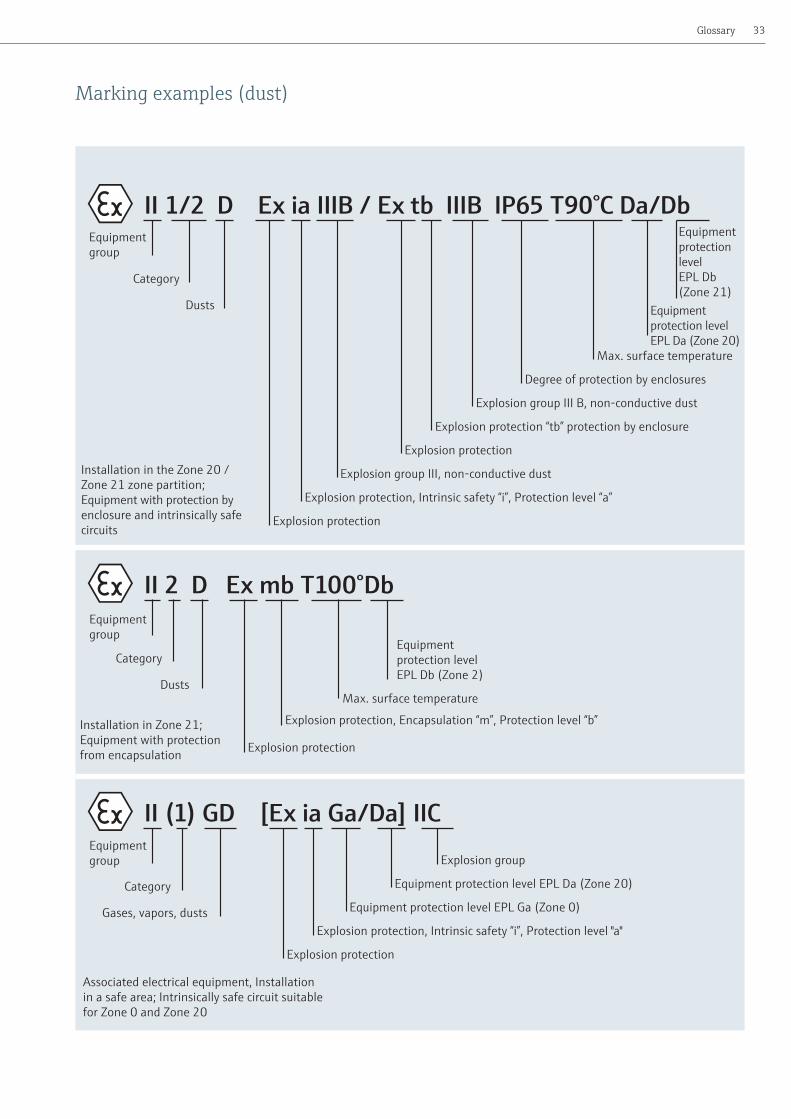
Marking examples (dust)
Explosion protection
II 1/2 D Ex ia IIIB / Ex tb IIIB IP65 T90°C Da/DbEquipment group
Category
Dusts
Explosion group III B, non-conductive dust
Degree of protection by enclosures
Max. surface temperature
Equipment protection level EPL Da (Zone 20)
Equipment protection level EPL Db (Zone 21)
Installation in the Zone 20 / Zone 21 zone partition; Equipment with protection by enclosure and intrinsically safe circuits
Explosion protection “tb” protection by enclosure
Explosion protection
Explosion group III, non-conductive dust
Explosion protection, Intrinsic safety “i”, Protection level “a”
II (1) GD [Ex ia Ga/Da] IICEquipment group
Category
Gases, vapors, dusts
Explosion protection
Equipment protection level EPL Ga (Zone 0)
Equipment protection level EPL Da (Zone 20)
Explosion protection, Intrinsic safety “i”, Protection level "a"
Explosion group
Associated electrical equipment, Installation in a safe area; Intrinsically safe circuit suitable for Zone 0 and Zone 20
II 2 D Ex mb T100°DbEquipment group
Category
Dusts
Explosion protection
Explosion protection, Encapsulation “m”, Protection level “b”Installation in Zone 21;Equipment with protection from encapsulation
Max. surface temperature
Equipment protection level EPL Db (Zone 2)
Glossary

© a
ndre
wbu
rges
s - F
otol
ia.co
m
Explosion protection34
Explosion protection terminology
Explosive atmosphere Mixture with air, under atmo-spheric conditions, of flammable substances in the form of gases, vapors, mists or dusts in which after ignition has occured, combustion spreads to the entire unburned mixture.
Potentially explosive atmosphere An atmosphere which could become explosive due to local and operational conditions.
Hazardous places (areas) A place in which an explosive atmosphere may occur in such quantities as to require special precautions to protect the health and safety of the workers. Hazardous places are classified in terms of Zones in Europe and at IEC and in divisions in North America.
Intrinsically safe circuit A circuit in which neither a spark nor a thermal effect can cause a certain potentially explo-sive atmosphere to ignite.
Electrical equipment The whole of components, electrical circuits or parts of electrical circuits usually found in a single enclosure.
Intrinsically safe electrical equipment Equipment in which all circuits are intrinsically safe.
Associated equipment Electrical equipment that includes both intrinsically safe and non-intrinsically safe circuits, and that is constructed so that the non-intrinsically safe circuits cannot impair the intrinsically safe circuits.Note:This can also be seen from the square brackets and paren-theses in the marking. Associated equipment has to be installed outside of the potentially explosive atmosphere if it does not correspond to another suitable type of explosion protection.
Simple electrical equipment Electrical equipment or a combination of components with a simple design and exactly specified electrical parameters that does not impair the intrinsic safety of the circuit in which it is to be used.

35Glossary

CP00
021Z
/11/
EN/1
3.13
– 7
1220
056
www.addresses.endress.com