EXPLOSION-PROOF CABLE GLAND - Type ICG 653 …...EXPLOSION-PROOF CABLE GLAND - Type ICG 653 Manual...
5
EXPLOSION-PROOF CABLE GLAND - Type ICG 653 Manual Sinus Jevi Electric Heating B.V. Aambeeld 19 1671 NT Medemblik The Netherlands tel. +31 (0)227-549 100 fax. +31 (0)227-549 150
Transcript of EXPLOSION-PROOF CABLE GLAND - Type ICG 653 …...EXPLOSION-PROOF CABLE GLAND - Type ICG 653 Manual...

EXPLOSION-PROOF CABLE GLAND - Type ICG 653Manual
Sinus Jevi Electric Heating B.V. Aambeeld 191671 NT MedemblikThe Netherlandstel. +31 (0)227-549 100fax. +31 (0)227-549 150

Sinus Jevi Electric Heating B.V. Aambeeld 191671 NT MedemblikThe Netherlandstel. +31 (0)227-549 100
INSTALLATION, OPERATION AND mAINTENANCE INSTRuCTIONS
CABLE GLAND - ICG 653
EXPLOSION PROOF CABLE GLAND - ICG 653
Page 2 of 8
EXPLOSION PROOF CABLE GLAND - ICG 653Page 3 of 8
Sinus Jevi Electric Heating B.V. Aambeeld 191671 NT MedemblikThe Netherlandstel. +31 (0)227-549 100
INSTALLATION, OPERATION AND mAINTENANCE INSTRuCTIONS
CABLE GLAND - ICG 653
Operating temperature range -60°C +80°C
1. Backnut2. Middle Nut 3. Reversible Armour Clamping Ring (RAC) 4. Armour Spigot 5. Rubber Pot 6. Entry (with captive deluge seal)
Reversible Armour Clamping Ring (RAC)General identification ring orientation for:
SWA Position
Braid ‘X’ Flat Steel Wire ‘Y‘
Steel Tape ‘Z‘ Ring Position
IMPORTANT: The arrowhead indicating the correct armour thickness or type should point towards the equipment
Certification DetailsGland Type: ICG 653/UNIV Exd IIC Gb / Extb IIIC Db
Baseefa06ATEX0058X ExII 2 GD IP66 CE IECEx BAS06.0015X
CEPEL 01.0065X GOST R No: POCC GB.605.B03785
c CSA us No: 1024328 Class 1 Zone AExd IIC, AExe II, Zone 21 AExtD Class 1 Div 2 ABCD, Class II Div 2 Groups EFG, Class III
CNEx12.3448X
Gland Type: 653/UNIV Ex d I Mb / Exe I Mb Baseefa08ATEX0329X exIM 2 IP66 CE
IECEx BAS08.0115X
AStrip Cable to suit equipment as shown above and expose the armour/braid ‘I’ removing all cable fillers. ‘I’ = 20mm for cable gland sizes Os to A ‘I’ = 25mm for cable gland sizes B to C2 ‘I’ = 32mm for cable gland sizes D to F ‘II’ = to suit equipment. If required, fit shroud. See Notes re. Drain Wires.
BPush the cable through the armour spigot ④. Spread armour/braid over the armour spigot ④ until the end of the armour/braid is up against the shoulder of the armour cone. Position the armour clamping ring ③.
CRemove the rubber pot ⑤ from the entry ⑥. Place the entry ⑥ over the armour spigot ④. Move thsub-assembly ① and ② up to meet the entry ⑥.
Cable preparation Gland preparation
Armour / braid
Shroud option
Note: Armour cable acceptance sizes are marked on the clamping ring.
DHold the entry ⑥ in position with a spanner /wrench to prevent rotation. Hand tighten the middle nut ② onto the entry ⑥ and turn a further half to three quarters of a turn with a spanner/wrench.
EUnscrew the middle nut ② and visually inspect that the armour/braid has been succesfully clamped between the armour spigot ④ and the armour clamping ring ③. If armour/braid not clamped repeat assembly.
FRemove the entry ⑥, spread the cable cores out for the compound packing. Pack the compound between the cores shown. See notes below and Fig. 7 for compound preperation.
EPOXY COMPOUND PREPERATIONWhen handling this material, the gloves supplied must be worn. The epoxy compound is supplied in the form of a two part package. These should be mixed into the ratio of 1:1 until both colours have blended into one, without any streaks. Rolling and folding is the most satisfactory method of obtaining an even blend. Once mixed, the compound must be used within 30 minutes. After this time it will begin to stiffen. The compound should be kept at an ambient temperature of no less than 20°C prior to using. At lower temperatures it becomes difficult to mix. Should any compound come into contact with the skin it should be cleaned off with skin cleaner and not allowed to dry on the skin. Only com-pound for immediate terminations should be mixed.
The mixing and installation of the compound at an ambient temperature below 4°C is not recommended due to extended curing periods.
The storage of the compound shall be at temperatures between 5°C and 30°C.
Sinus Jevi Electric Heating B.V. Aambeeld 191671 NT MedemblikThe Netherlandstel. +31 (0)227-549 100
INSTALLATION, OPERATION AND mAINTENANCE INSTRuCTIONS
CABLE GLAND - ICG 653
EXPLOSION PROOF CABLE GLAND - ICG 653
Page 4 of 8
EXPLOSION PROOF CABLE GLAND - ICG 653Page 5 of 8
Sinus Jevi Electric Heating B.V. Aambeeld 191671 NT MedemblikThe Netherlandstel. +31 (0)227-549 100
INSTALLATION, OPERATION AND mAINTENANCE INSTRuCTIONS
CABLE GLAND - ICG 653
Armour / braid One or two groups of screen wires
Crimp or Solder
Insulated Condustor
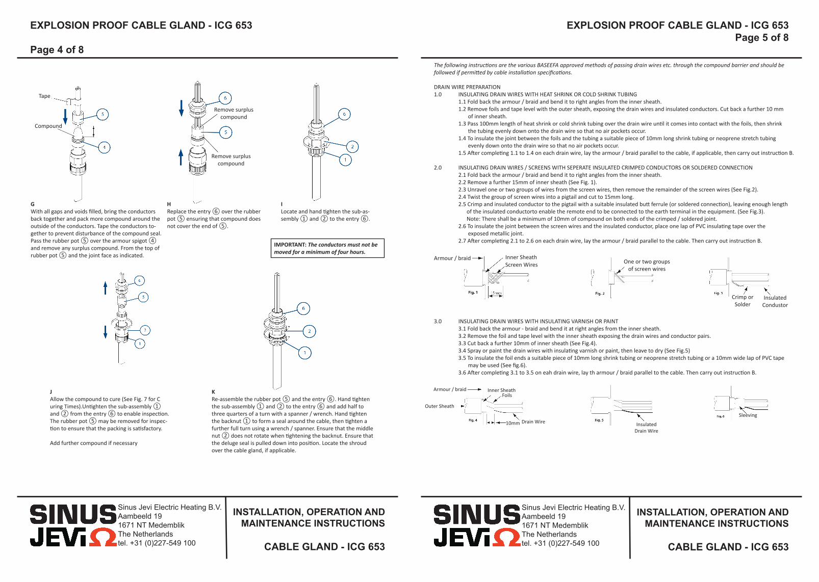
JAllow the compound to cure (See Fig. 7 for C uring Times).Untighten the sub-assembly ① and ② from the entry ⑥ to enable inspection. The rubber pot ⑤ may be removed for inspec-tion to ensure that the packing is satisfactory.
Add further compound if necessary
KRe-assemble the rubber pot ⑤ and the entry ⑥. Hand tighten the sub-assembly ① and ② to the entry ⑥ and add half to three quarters of a turn with a spanner / wrench. Hand tighten the backnut ① to form a seal around the cable, then tighten a further full turn using a wrench / spanner. Ensure that the middle nut ② does not rotate when tightening the backnut. Ensure that the deluge seal is pulled down into position. Locate the shroud over the cable gland, if applicable.
The following instructions are the various BASEEFA approved methods of passing drain wires etc. through the compound barrier and should be followed if permitted by cable installation specifications.
DRAIN WIRE PREPARATION 1.0 INSULATING DRAIN WIRES WITH HEAT SHRINK OR COLD SHRINK TUBING 1.1 Fold back the armour / braid and bend it to right angles from the inner sheath. 1.2 Remove foils and tape level with the outer sheath, exposing the drain wires and insulated conductors. Cut back a further 10 mm of inner sheath. 1.3 Pass 100mm length of heat shrink or cold shrink tubing over the drain wire until it comes into contact with the foils, then shrink the tubing evenly down onto the drain wire so that no air pockets occur. 1.4 To insulate the joint between the foils and the tubing a suitable piece of 10mm long shrink tubing or neoprene stretch tubing evenly down onto the drain wire so that no air pockets occur. 1.5 After completing 1.1 to 1.4 on each drain wire, lay the armour / braid parallel to the cable, if applicable, then carry out instruction B.
2.0 INSULATING DRAIN WIRES / SCREENS WITH SEPERATE INSULATED CRIMPED CONDUCTORS OR SOLDERED CONNECTION 2.1 Fold back the armour / braid and bend it to right angles from the inner sheath. 2.2 Remove a further 15mm of inner sheath (See Fig. 1). 2.3 Unravel one or two groups of wires from the screen wires, then remove the remainder of the screen wires (See Fig.2). 2.4 Twist the group of screen wires into a pigtail and cut to 15mm long. 2.5 Crimp and insulated conductor to the pigtail with a suitable insulated butt ferrule (or soldered connection), leaving enough length of the insulated conductorto enable the remote end to be connected to the earth terminal in the equipment. (See Fig.3). Note: There shall be a minimum of 10mm of compound on both ends of the crimped / soldered joint. 2.6 To insulate the joint between the screen wires and the insulated conductor, place one lap of PVC insulating tape over the exposed metallic joint. 2.7 After completing 2.1 to 2.6 on each drain wire, lay the armour / braid parallel to the cable. Then carry out instruction B.
3.0 INSULATING DRAIN WIRES WITH INSULATING VARNISH OR PAINT 3.1 Fold back the armour - braid and bend it at right angles from the inner sheath. 3.2 Remove the foil and tape level with the inner sheath exposing the drain wires and conductor pairs. 3.3 Cut back a further 10mm of inner sheath (See Fig.4). 3.4 Spray or paint the drain wires with insulating varnish or paint, then leave to dry (See Fig.5) 3.5 To insulate the foil ends a suitable piece of 10mm long shrink tubing or neoprene stretch tubing or a 10mm wide lap of PVC tape may be used (See fig.6). 3.6 After completing 3.1 to 3.5 on eah drain wire, lay th armour / braid parallel to the cable. Then carry out instruction B.
Inner SheathScreen Wires
Armour / braid
Outer Sheath
Inner SheathFoils
Drain Wire10mm Insulated Drain Wire
Sleeving
GWith all gaps and voids filled, bring the conductors back together and pack more compound around the outside of the conductors. Tape the conductors to-gether to prevent disturbance of the compound seal. Pass the rubber pot ⑤ over the armour spigot ④ and remove any surplus compound. From the top of rubber pot ⑤ and the joint face as indicated.
HReplace the entry ⑥ over the rubber pot ⑤ ensuring that compound does not cover the end of ⑤.
ILocate and hand tighten the sub-as-sembly ① and ② to the entry ⑥.
IMPORTANT: The conductors must not be moved for a minimum of four hours.
Tape
Compound
Remove surplus compound
Remove surplus compound

Sinus Jevi Electric Heating B.V. Aambeeld 191671 NT MedemblikThe Netherlandstel. +31 (0)227-549 100
INSTALLATION, OPERATION AND mAINTENANCE INSTRuCTIONS
CABLE GLAND - ICG 653
EXPLOSION PROOF CABLE GLAND - ICG 653
Page 6 of 8
EXPLOSION PROOF CABLE GLAND - ICG 653Page 7 of 8
Sinus Jevi Electric Heating B.V. Aambeeld 191671 NT MedemblikThe Netherlandstel. +31 (0)227-549 100
INSTALLATION, OPERATION AND mAINTENANCE INSTRuCTIONS
CABLE GLAND - ICG 653
● The compound may be adversely affected by some solvent vapours. If such vapours are likely to be present in the vicnity of the cable gland in service, suitable precautions may be necessary.
● The compound cures at a Shore D hardness of 85, when it can be handled. The compound when fully cured is suitable for use at a temperature range of -60° to +80°C.
Shor
e Ha
rdne
ss
Time (hours)
Epoxy Compound Cure Time vs. Temperature
Size Ref
Entry Thread SizeCable Acceptance Details
Com
pres
sed
Len
gth
Max
imum
Le
ngth
Heaxagon Dimen-sionsInner Sheath/Cores Outer
SheathSteel Wire Armour/Tape/Braid
Metric NPT Max. Over Cores
Max. Inner Sheath
Note 1Max. No. of Cores
Note 2Max. No. of Cores
Min. Max. Orientation 1
Orientation 2 Across
FlatsAcross
Corners
Os M20 ½” 8.9 10.0 12 6 5.5 12.0 0.8/1.25 0/0.8 67.0 83.0 24.0 26.5
O M20 ½” 8.9 10.0 12 6 9.5 16.0 0.8/1.25 0/0.8 67.0 83.0 24.0 26.5
A M20 ½” - ¾” 11.0 12.5 15 10 12.5 20.5 0.8/1.25 0/0.8 67.0 84.0 30.0 32.5
B M25 ¾” - 1” 16.2 18.4 30 21 16.9 26.0 1.25/1.6 0/0.7 73.6 91.0 36.0 39.5
C M32 1” - 1¼” 21.9 24.7 42 42 22.0 33.0 1.6/2.0 0/0.7 78.0 98.0 46.0 50.5
C2 M40 1¼” - 1½” 26.3 29.7 60 60 28.0 41.0 1.6/2.0 0/0.7 82.4 100.0 55.0 60.6
D M50 1½” - 2” 37.1 41.7 80 80 36.0 52.6 1.8/2.5 0/1.0 88.7 116.0 65.0 70.8
E M63 2” - 2½” 47.8 53.5 100 100 46.0 65.3 1.8/2.5 0/1.0 92.7 124.0 80.0 88.0
F M75 2 ½” - 3” 59.0 66.2/65.3 120 120 57.0 78.0 1.8/2.5 0/1.0 99.4 122.0 95.0 104.0
Note 1: ATEX / IECEx certification onlyNote 2: All other certification
ACCESSORIESBefore cable gland assembly or stripping of the cable gland assembly, consideration should be given to any cable gland accessories that may be required, such as: ● Shroud, to offer additional corrosion protection. ● Locknut, to secure cable glands into position. ● Sealing washer, to offer additional ingress protection of the enclosure at the cable gland entry. ● Earthtag, to provide an external armour / braid bonding point. ● Serrated washer, to dampen any vibrations that may loosen the locknut or cable gland assembly.
SChEDUlE Of lIMITATIONS - Baseefa ATEX / IECEx:1. These glands are suitable for use within an operating temperature range of -60°C to +80°C.
2. When the gland is used for increased safety, the entry thread shall be suitably sealed to maintain the ingress protection rating of the associated enclosure.
3. When used with steel basket weave armour or braided cable, the cable must be clamped and cleated to prevent pulling on the armour or braid of the cable
NOTES - c CSA us:1. Class 1 Division 2 suitable for Marine Shipboard applications only according to CSA Standard 245 and IEEE45 / IEC 600092-353 Standards, or certified equivalent, for use on Shipboards and Offshore Rigs / Platforms only.
2. Glands must comply with the Canadian Electrical Code and National Electric Code requirements for threaded entries.
3. For Exe applications, a sealing washer or thread sealant may be required between the enclosure and the gland to maintain the IP rating of the enclosure.
4. Drain wires and earth screening may pass through the compound barrier using one of the methods which are details in this assembly instruction; heat shrink or cold shrink tubing, or addition of an insulated crimped or soldered conductor or insulation by varnish or paint.
5. This cable gland may only be installed when temperature is above +4°C. After completion of the installation, the assembly is then suitable for -60°C to +80°C.
For more information about choosing the correct cable gland, find the selection diagram on the last page.

Sinus Jevi Electric Heating B.V. Aambeeld 191671 NT MedemblikThe Netherlandstel. +31 (0)227-549 100
No rights can be derived from the text, illustrations and samples.We reserve the right to change materials, parts, assemblies, designs, colours, finishes etc. without prior notification.
G.S
162B
.110
1 • 1
2-14
For certificates please visit www.ehawke.com