Exploring the Tradeoffs between Programmability and Efficiency … · Exploring the Tradeoffs...
12
Exploring the Tradeoffs between Programmability and Efficiency in Data-Parallel Accelerators Yunsup Lee * , Rimas Avizienis * , Alex Bishara * , Richard Xia * , Derek Lockhart † , Christopher Batten † , and Krste Asanovi´ c * * Department of Electrical Engineering and Computer Science University of California, Berkeley, CA {yunsup,rimas,abishara,rxia,krste}@eecs.berkeley.edu † School of Electrical and Computer Engineering Cornell University, Ithaca, NY {dml257,cbatten}@cornell.edu ABSTRACT We present a taxonomy and modular implementation approach for data-parallel accelerators, including the MIMD, vector-SIMD, subword-SIMD, SIMT, and vector-thread (VT) architectural design patterns. We have developed a new VT microarchitecture, Maven, based on the traditional vector-SIMD microarchitecture that is con- siderably simpler to implement and easier to program than previ- ous VT designs. Using an extensive design-space exploration of full VLSI implementations of many accelerator design points, we evaluate the varying tradeoffs between programmability and imple- mentation efficiency among the MIMD, vector-SIMD, and VT pat- terns on a workload of microbenchmarks and compiled application kernels. We find the vector cores provide greater efficiency than the MIMD cores, even on fairly irregular kernels. Our results sug- gest that the Maven VT microarchitecture is superior to the tradi- tional vector-SIMD architecture, providing both greater efficiency and easier programmability. Categories and Subject Descriptors C.1.2 [Processor Architectures]: Multiple Data Stream Architec- tures—array and vector processors, MIMD, SIMD General Terms Design 1. INTRODUCTION Data-parallel kernels dominate the computational workload in a wide variety of demanding application domains, including graph- ics rendering, computer vision, audio processing, physical simu- lation, and machine learning. Specialized data-parallel accelera- tors [6, 8, 10, 16, 22] have long been known to provide greater en- ergy and area efficiency than general-purpose processors for codes with significant amounts of data-level parallelism (DLP). With con- tinuing improvements in transistor density and an increasing em- phasis on energy efficiency, there has recently been growing inter- est in DLP accelerators for mainstream computing environments. Permission to make digital or hard copies of all or part of this work for personal or classroom use is granted without fee provided that copies are not made or distributed for profit or commercial advantage and that copies bear this notice and the full citation on the first page. To copy otherwise, to republish, to post on servers or to redistribute to lists, requires prior specific permission and/or a fee. ISCA’11, June 4–8, 2011, San Jose, California, USA. Copyright 2011 ACM 978-1-4503-0472-6/11/06 ...$10.00 These accelerators are usually attached to a general-purpose host processor, either on the same die or a separate die. The host pro- cessor executes system code and non-DLP application code while distributing DLP kernels to the accelerator. Surveying the wide range of data-parallel accelerator cores in industry and academia reveals a general tradeoff between programmability (how easy is it to write software for the accelerator?) and efficiency (energy/task and tasks/second/area). In this paper, we examine multiple alter- native data-parallel accelerators to quantify the efficiency impact of microarchitectural features intended to simplify programming or expand the range of code that can be executed. We first introduce a set of five architectural design patterns for DLP cores in Section 2, qualitatively comparing their expected pro- grammability and efficiency. The MIMD pattern [8] flexibly sup- ports mapping data-parallel tasks to a collection of simple scalar or multithreaded cores, but lacks mechanisms for efficient exe- cution of regular DLP. The vector-SIMD [19, 22] and subword- SIMD [6] patterns can significantly reduce the energy on reg- ular DLP, but can require complicated programming for irregu- lar DLP. The single-instruction multiple-thread (SIMT) [12] and vector-thread (VT) [10] patterns are hybrids between the MIMD and vector-SIMD patterns that attempt to offer alternative tradeoffs between programmability and efficiency. When reducing these high-level patterns to an efficient VLSI de- sign, there is a large design space to explore. In Section 3, we present a common set of parameterized synthesizable microarchi- tectural components and show how these can be combined to form complete RTL designs for the different architectural design pat- terns, thereby reducing total design effort and allowing a fairer com- parison across patterns. In this section, we also introduce Maven, a new VT microarchitecture. Our modular design strategy revealed a much simpler and more efficient implementation than the ear- lier Scale VT design [9, 10]. Maven [2, 11] is based on a vector- SIMD microarchitecture with only the minimum number of hard- ware mechanisms added to enable the improved programmabil- ity from VT, instead of the decoupled cluster microarchitecture of Scale. Another innovation in Maven is to use the same RISC ISA for both vector and scalar code, greatly reducing the effort required to develop an efficient VT compiler. The Scale design required a separate clustered ISA for vector code, which complicated com- piler development [7]. To concretely evaluate and compare the efficiency of these pat- terns, we have generated and analyzed hundreds of complete VLSI layouts for the MIMD, vector-SIMD, and VT patterns using our parameterized microarchitecture components targeting a modern 65 nm technology. Sections 4 describes our methodology for ex-
-
Upload
trinhkhuong -
Category
Documents
-
view
219 -
download
0
Transcript of Exploring the Tradeoffs between Programmability and Efficiency … · Exploring the Tradeoffs...

Exploring the Tradeoffs between Programmability andEfficiency in Data-Parallel Accelerators
Yunsup Lee*, Rimas Avizienis*, Alex Bishara*, Richard Xia*, Derek Lockhart†,Christopher Batten†, and Krste Asanovic*
*Department of Electrical Engineering and Computer ScienceUniversity of California, Berkeley, CA
{yunsup,rimas,abishara,rxia,krste}@eecs.berkeley.edu
†School of Electrical and Computer EngineeringCornell University, Ithaca, NY
{dml257,cbatten}@cornell.edu
ABSTRACTWe present a taxonomy and modular implementation approachfor data-parallel accelerators, including the MIMD, vector-SIMD,subword-SIMD, SIMT, and vector-thread (VT) architectural designpatterns. We have developed a new VT microarchitecture, Maven,based on the traditional vector-SIMD microarchitecture that is con-siderably simpler to implement and easier to program than previ-ous VT designs. Using an extensive design-space exploration offull VLSI implementations of many accelerator design points, weevaluate the varying tradeoffs between programmability and imple-mentation efficiency among the MIMD, vector-SIMD, and VT pat-terns on a workload of microbenchmarks and compiled applicationkernels. We find the vector cores provide greater efficiency thanthe MIMD cores, even on fairly irregular kernels. Our results sug-gest that the Maven VT microarchitecture is superior to the tradi-tional vector-SIMD architecture, providing both greater efficiencyand easier programmability.
Categories and Subject DescriptorsC.1.2 [Processor Architectures]: Multiple Data Stream Architec-tures—array and vector processors, MIMD, SIMD
General TermsDesign
1. INTRODUCTIONData-parallel kernels dominate the computational workload in a
wide variety of demanding application domains, including graph-ics rendering, computer vision, audio processing, physical simu-lation, and machine learning. Specialized data-parallel accelera-tors [6, 8, 10, 16, 22] have long been known to provide greater en-ergy and area efficiency than general-purpose processors for codeswith significant amounts of data-level parallelism (DLP). With con-tinuing improvements in transistor density and an increasing em-phasis on energy efficiency, there has recently been growing inter-est in DLP accelerators for mainstream computing environments.
Permission to make digital or hard copies of all or part of this work forpersonal or classroom use is granted without fee provided that copies arenot made or distributed for profit or commercial advantage and that copiesbear this notice and the full citation on the first page. To copy otherwise, torepublish, to post on servers or to redistribute to lists, requires prior specificpermission and/or a fee.ISCA’11, June 4–8, 2011, San Jose, California, USA.Copyright 2011 ACM 978-1-4503-0472-6/11/06 ...$10.00
These accelerators are usually attached to a general-purpose hostprocessor, either on the same die or a separate die. The host pro-cessor executes system code and non-DLP application code whiledistributing DLP kernels to the accelerator. Surveying the widerange of data-parallel accelerator cores in industry and academiareveals a general tradeoff between programmability (how easy is itto write software for the accelerator?) and efficiency (energy/taskand tasks/second/area). In this paper, we examine multiple alter-native data-parallel accelerators to quantify the efficiency impactof microarchitectural features intended to simplify programming orexpand the range of code that can be executed.
We first introduce a set of five architectural design patterns forDLP cores in Section 2, qualitatively comparing their expected pro-grammability and efficiency. The MIMD pattern [8] flexibly sup-ports mapping data-parallel tasks to a collection of simple scalaror multithreaded cores, but lacks mechanisms for efficient exe-cution of regular DLP. The vector-SIMD [19, 22] and subword-SIMD [6] patterns can significantly reduce the energy on reg-ular DLP, but can require complicated programming for irregu-lar DLP. The single-instruction multiple-thread (SIMT) [12] andvector-thread (VT) [10] patterns are hybrids between the MIMDand vector-SIMD patterns that attempt to offer alternative tradeoffsbetween programmability and efficiency.
When reducing these high-level patterns to an efficient VLSI de-sign, there is a large design space to explore. In Section 3, wepresent a common set of parameterized synthesizable microarchi-tectural components and show how these can be combined to formcomplete RTL designs for the different architectural design pat-terns, thereby reducing total design effort and allowing a fairer com-parison across patterns. In this section, we also introduce Maven, anew VT microarchitecture. Our modular design strategy revealeda much simpler and more efficient implementation than the ear-lier Scale VT design [9, 10]. Maven [2, 11] is based on a vector-SIMD microarchitecture with only the minimum number of hard-ware mechanisms added to enable the improved programmabil-ity from VT, instead of the decoupled cluster microarchitecture ofScale. Another innovation in Maven is to use the same RISC ISAfor both vector and scalar code, greatly reducing the effort requiredto develop an efficient VT compiler. The Scale design required aseparate clustered ISA for vector code, which complicated com-piler development [7].
To concretely evaluate and compare the efficiency of these pat-terns, we have generated and analyzed hundreds of complete VLSIlayouts for the MIMD, vector-SIMD, and VT patterns using ourparameterized microarchitecture components targeting a modern65 nm technology. Sections 4 describes our methodology for ex-
tracting area, energy, and performance numbers for a range ofmicrobenchmarks and compiled application kernels. Section 5presents and analyzes our results.
Our results show that vector cores are considerably more effi-cient in both energy and area-normalized performance than MIMDcores, although the MIMD cores are usually easier to program. Ourresults also suggest that the Maven VT microarchitecture is superiorto the traditional vector-SIMD architecture, providing greater effi-ciency and a simpler programming model. For both VT and vector-SIMD, multi-lane implementations are usually more efficient thanmulti-core single-lane implementations and can be easier to pro-gram as they require less partitioning and load balancing. Althoughwe do not implement a SIMT machine, some initial analysis indi-cates SIMT will be less efficient than VT but should be easier toprogram.
2. ARCHITECTURAL DESIGN PATTERNSWe begin by categorizing kernels encountered in data-parallel
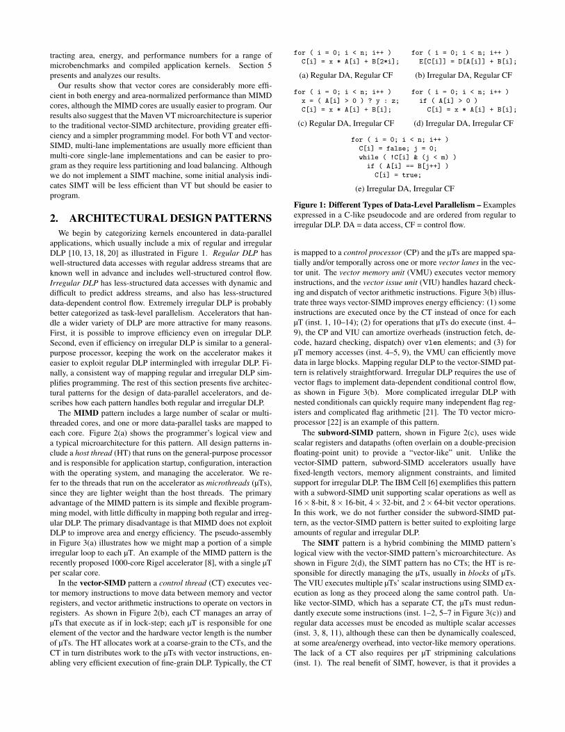
applications, which usually include a mix of regular and irregularDLP [10, 13, 18, 20] as illustrated in Figure 1. Regular DLP haswell-structured data accesses with regular address streams that areknown well in advance and includes well-structured control flow.Irregular DLP has less-structured data accesses with dynamic anddifficult to predict address streams, and also has less-structureddata-dependent control flow. Extremely irregular DLP is probablybetter categorized as task-level parallelism. Accelerators that han-dle a wider variety of DLP are more attractive for many reasons.First, it is possible to improve efficiency even on irregular DLP.Second, even if efficiency on irregular DLP is similar to a general-purpose processor, keeping the work on the accelerator makes iteasier to exploit regular DLP intermingled with irregular DLP. Fi-nally, a consistent way of mapping regular and irregular DLP sim-plifies programming. The rest of this section presents five architec-tural patterns for the design of data-parallel accelerators, and de-scribes how each pattern handles both regular and irregular DLP.
The MIMD pattern includes a large number of scalar or multi-threaded cores, and one or more data-parallel tasks are mapped toeach core. Figure 2(a) shows the programmer’s logical view anda typical microarchitecture for this pattern. All design patterns in-clude a host thread (HT) that runs on the general-purpose processorand is responsible for application startup, configuration, interactionwith the operating system, and managing the accelerator. We re-fer to the threads that run on the accelerator as microthreads (µTs),since they are lighter weight than the host threads. The primaryadvantage of the MIMD pattern is its simple and flexible program-ming model, with little difficulty in mapping both regular and irreg-ular DLP. The primary disadvantage is that MIMD does not exploitDLP to improve area and energy efficiency. The pseudo-assemblyin Figure 3(a) illustrates how we might map a portion of a simpleirregular loop to each µT. An example of the MIMD pattern is therecently proposed 1000-core Rigel accelerator [8], with a single µTper scalar core.
In the vector-SIMD pattern a control thread (CT) executes vec-tor memory instructions to move data between memory and vectorregisters, and vector arithmetic instructions to operate on vectors inregisters. As shown in Figure 2(b), each CT manages an array ofµTs that execute as if in lock-step; each µT is responsible for oneelement of the vector and the hardware vector length is the numberof µTs. The HT allocates work at a coarse-grain to the CTs, and theCT in turn distributes work to the µTs with vector instructions, en-abling very efficient execution of fine-grain DLP. Typically, the CT
for ( i = 0; i < n; i++ )C[i] = x * A[i] + B[2*i];
(a) Regular DA, Regular CF
for ( i = 0; i < n; i++ )x = ( A[i] > 0 ) ? y : z;C[i] = x * A[i] + B[i];
(c) Regular DA, Irregular CF
for ( i = 0; i < n; i++ )E[C[i]] = D[A[i]] + B[i];
(b) Irregular DA, Regular CF
for ( i = 0; i < n; i++ )if ( A[i] > 0 )
C[i] = x * A[i] + B[i];
(d) Irregular DA, Irregular CF
for ( i = 0; i < n; i++ )C[i] = false; j = 0;while ( !C[i] & (j < m) )
if ( A[i] == B[j++] )C[i] = true;
(e) Irregular DA, Irregular CF
Figure 1: Different Types of Data-Level Parallelism – Examplesexpressed in a C-like pseudocode and are ordered from regular toirregular DLP. DA = data access, CF = control flow.
is mapped to a control processor (CP) and the µTs are mapped spa-tially and/or temporally across one or more vector lanes in the vec-tor unit. The vector memory unit (VMU) executes vector memoryinstructions, and the vector issue unit (VIU) handles hazard check-ing and dispatch of vector arithmetic instructions. Figure 3(b) illus-trate three ways vector-SIMD improves energy efficiency: (1) someinstructions are executed once by the CT instead of once for eachµT (inst. 1, 10–14); (2) for operations that µTs do execute (inst. 4–9), the CP and VIU can amortize overheads (instruction fetch, de-code, hazard checking, dispatch) over vlen elements; and (3) forµT memory accesses (inst. 4–5, 9), the VMU can efficiently movedata in large blocks. Mapping regular DLP to the vector-SIMD pat-tern is relatively straightforward. Irregular DLP requires the use ofvector flags to implement data-dependent conditional control flow,as shown in Figure 3(b). More complicated irregular DLP withnested conditionals can quickly require many independent flag reg-isters and complicated flag arithmetic [21]. The T0 vector micro-processor [22] is an example of this pattern.
The subword-SIMD pattern, shown in Figure 2(c), uses widescalar registers and datapaths (often overlain on a double-precisionfloating-point unit) to provide a “vector-like” unit. Unlike thevector-SIMD pattern, subword-SIMD accelerators usually havefixed-length vectors, memory alignment constraints, and limitedsupport for irregular DLP. The IBM Cell [6] exemplifies this patternwith a subword-SIMD unit supporting scalar operations as well as16! 8-bit, 8! 16-bit, 4! 32-bit, and 2! 64-bit vector operations.In this work, we do not further consider the subword-SIMD pat-tern, as the vector-SIMD pattern is better suited to exploiting largeamounts of regular and irregular DLP.
The SIMT pattern is a hybrid combining the MIMD pattern’slogical view with the vector-SIMD pattern’s microarchitecture. Asshown in Figure 2(d), the SIMT pattern has no CTs; the HT is re-sponsible for directly managing the µTs, usually in blocks of µTs.The VIU executes multiple µTs’ scalar instructions using SIMD ex-ecution as long as they proceed along the same control path. Un-like vector-SIMD, which has a separate CT, the µTs must redun-dantly execute some instructions (inst. 1–2, 5–7 in Figure 3(c)) andregular data accesses must be encoded as multiple scalar accesses(inst. 3, 8, 11), although these can then be dynamically coalesced,at some area/energy overhead, into vector-like memory operations.The lack of a CT also requires per µT stripmining calculations(inst. 1). The real benefit of SIMT, however, is that it provides a

Figure 2: Architectural Design Patterns – Programmer’s logical view and a typical core microarchitecture for five patterns: (a) MIMD,(b) vector-SIMD, (c) subword-SIMD, (d) SIMT, and (e) VT. HT = host thread, CT = control thread, CP = control processor, µT = microthread,VIU = vector issue unit, VMU = vector memory unit.

1 div m, n, nthr2 mul t, m, tidx3 add a_ptr, t4 add b_ptr, t5 add c_ptr, t6 sub t, nthr, 17 br.neq t, tidx, ex8 rem m, n, nthr9 ex:
10 load x, x_ptr11 loop:12 load a, a_ptr13 br.eq a, 0, done14 load b, b_ptr15 mul t, x, a16 add c, t, b17 store c, c_ptr18 done:19 add a_ptr, 120 add b_ptr, 121 add c_ptr, 122 sub m, 123 br.neq m, 0, loop
(a) MIMD
1 load x, x_ptr2 loop:3 setvl vlen, n4 load.v VA, a_ptr5 load.v VB, b_ptr6 cmp.gt.v VF, VA, 07 mul.sv VT, x, VA, VF8 add.vv VC, VT, VB, VF9 store.v VC, c_ptr, VF
10 add a_ptr, vlen11 add b_ptr, vlen12 add c_ptr, vlen13 sub n, vlen14 br.neq n, 0, loop
(b) Vector-SIMD
1 br.gte tidx, n, done2 add a_ptr, tidx3 load a, a_ptr4 br.eq a, 0, done5 add b_ptr, tidx6 add c_ptr, tidx7 load x, x_ptr8 load b, b_ptr9 mul t, x, a
10 add c, t, b11 store c, c_ptr12 done:
(c) SIMT
1 load x, x_ptr2 mov.sv VZ, x3 loop:4 setvl vlen, n5 load.v VA, a_ptr6 load.v VB, b_ptr7 mov.sv VD, c_ptr8 fetch.v ut_code9 add a_ptr, vlen
10 add b_ptr, vlen11 add c_ptr, vlen12 sub n, vlen13 br.neq n, 0, loop14 ...15 ut_code:16 br.eq a, 0, done17 mul t, z, a18 add c, t, b19 add d, tidx20 store c, d21 done:22 stop
(d) VT
Figure 3: Pseudo-Assembly for Irregular DLP Example – Pseudo-assembly implements the loop in Figure 1(d) for the (a) MIMD,(b) vector-SIMD, (c) SIMT, and (d) VT patterns. Assume *_ptr and nare inputs. Vi = vector register i, VF = vector flag register, *.v = vectorcommand, *.vv = vector-vector op, *.sv = scalar-vector op, nthr =number of µTs, tidx = current microthread’s index.
simple way to map complex data-dependent control flow with µTscalar branches (inst. 4). If the µTs diverge at a branch, the VIUuses internally generated masks to disable inactive µTs along eachpath. The NVIDIA Fermi graphics processor [16] exemplifies thispattern with 32 multithreaded SIMT cores each with 16 lanes.
The VT pattern is also a hybrid but takes a very different ap-proach from SIMT. As shown in Figure 2(e), the HT manages acollection of CTs, and each CT in turn manages an array of µTs.Figure 3(d) shows example VT assembly code. Like vector-SIMD,the CT can amortize control overheads and execute efficient vec-tor memory instructions. Unlike vector-SIMD, the CT can use avector-fetch instruction (inst. 8) to indicate the start of a scalar in-struction stream that should be executed by the µTs. Explicit stopinstructions (inst. 22) indicate a µT has finished the vector-fetchedstream, and all µTs reconverge at the next vector fetch. As in SIMT,the VT VIU will try to execute across the µTs in a SIMD manner,but a vector-fetched scalar branch (inst. 16) can cause the µTs todiverge. Maven, introduced in this paper, and the earlier Scale [10]processor are examples of VT.
3. MICROARCHITECTURE OF MIMD,VECTOR-SIMD, AND VT TILES
In this section, we describe in detail the microarchitectures usedto evaluate the various patterns. A data-parallel accelerator willusually include an array of tiles and an on-chip network to connectthem to each other and an outer-level memory system, as shown inFigure 4(a). Each tile includes one or more tightly coupled coresand their caches, with examples in Figure 4(b)–(d). In this paper,we focus on comparing the various architectural design patternswith respect to a single data-parallel tile. The inter-tile intercon-nect and memory system are also critical components of a DLPaccelerator system, but are outside the scope of this work.
3.1 Microarchitectural ComponentsWe developed a library of parameterized synthesizable RTL com-
ponents that can be combined to construct MIMD, vector-SIMDand VT tiles. Our library includes long-latency functional units,
a multi-threaded scalar integer core, vector lanes, vector memoryunits, vector issue units, and blocking and non-blocking caches.
A set of long-latency functional units provide support for inte-ger multiplication and division, and IEEE single-precision floating-point addition, multiplication, division, and square root. Theseunits can be flexibly retimed to meet various cycle-time constraints.
Our scalar integer core implements a RISC ISA, with basicinteger instructions executed in a five-stage, in-order pipeline butwith two sets of request/response queues for attaching the core tothe memory system and long-latency functional units. A two-read-port/two-write-port (2r2w-port) 32-entry 32-bit regfile holds bothinteger and floating-point values. One write port is for the inte-ger pipeline and the other is shared by the memory system andlong-latency functional units. The core can be multithreaded, withreplicated architectural state for each thread and a dynamic threadscheduling stage at the front of the pipeline.
Figure 5 shows the microarchitectural template used for all thevector-based cores. A control processor (CP) sends vector instruc-tions to the vector unit, which includes one or more vector lanes, avector memory unit (VMU), and a vector issue unit (VIU). The laneand VMU components are nearly identical in all of the vector-basedcores, but the VIU differs significantly between the vector-SIMDand VT cores as discussed below.
Our baseline vector lane consists of a unified 6r3w-port vectorregfile and five vector functional units (VFUs): two arithmetic units(VAUs), a load unit (VLU), a store unit (VSU), and an address-generation unit (VGU). Each VAU contains an integer ALU and asubset of the long-latency functional units. The vector regfile canbe dynamically reconfigured to support between 4–32 registers perµT with corresponding changes in maximum vector length (32–1).Each VFU has a sequencer to step through elements of each vectoroperation, generating physical register addresses.
The vector memory unit coordinates data movement betweenthe memory system and the vector regfile using decoupling [5]. TheCP splits each vector memory instruction into a vector memory µopissued to the VMU and a vector register access µop sent to the VIU,which is eventually issued to the VLU or VSU in the vector lane. Aload µop causes the VMU to issue a vector’s worth of load requests

(a) Data-ParallelAccelerator
(b) MIMD Tile withFour Cores
(c) Vector-SIMD Tile withFour Single-Lane Cores
(d) Vector-SIMD Tile withOne Four-Lane Core
Figure 4: Example Data-Parallel Tile Configurations
(a) Baseline Vector-SIMD and VT Core Microarchitecture (b) Banked Regfile w/ Per-Bank Int ALUs
Figure 5: Vector-Based Core Microarchitecture – (a) Each vector-based core includes one or more vector lanes, vector memory unit, andvector issue unit; PVFB = pending vector fragment buffer, PC = program counter, VAU = vector arithmetic unit, VLU = vector load-datawriteback unit, VSU = vector store-data read unit, VGU = address generation unit for µT loads/stores, VLDQ = vector load-data queue,VSDQ = vector store-data queue, VLAGU/VSAGU = address generation unit for vector loads/stores, µTAQ = µT address queue, µTLDQ =µT load-data queue, µTSDQ = µT store-data queue. Modules specific to vector-SIMD or VT cores are highlighted. (b) Changes required toimplement intra-lane vector regfile banking with per-bank integer ALUs.

to the memory system, with data returned to the vector load dataqueue (VLDQ). As data becomes available, the VLU copies it fromthe VLDQ to the vector regfile. A store µop causes the VMU toretrieve a vector’s worth of data from the vector store data queue(VSDQ) as it is pushed onto the queue by the VSU. Note that forsingle-lane configurations, the VMU still uses wide accesses be-tween the VLDQ/VSDQ and the memory system, but moves databetween the VLDQ/VSDQ and the vector lane one element at atime. Individual µT loads and stores (gathers and scatters) are han-dled similarly, except addresses are generated by the VGU and dataflows through separate queues.
The main difference between vector-SIMD and VT cores is howthe vector issue unit fetches instructions and handles conditionalcontrol flow. In a vector-SIMD core, the CP sends individual vec-tor instructions to the VIU, which is responsible for ensuring that allhazards have been resolved before sending vector µops to the vectorlane. Our vector-SIMD ISA supports data-dependent control flowusing conventional vector masking, with eight single-bit flag regis-ters. A µT is prevented from writing results for a vector instructionwhen the associated bit in a selected flag register is clear.
In our VT core, the CP sends vector-fetch instructions to the VIU.For each vector fetch, the VIU creates a new vector fragment con-sisting of a program counter, initialized to the start address speci-fied in the vector fetch, and an active µT bit mask, initialized to allactive. The VIU then fetches and executes the corresponding se-quential instruction stream across all active µTs, sending a vectorµop plus active µT mask to the vector lane for each instruction. TheVIU handles a branch instruction by issuing a compare µop to oneof the VFUs, which then produces a branch-resolution bit mask. Ifthe mask is all zeros or ones, the VIU continues fetching scalar in-structions along the fall-through or taken path. Otherwise, the µTshave diverged and so the VIU splits the current fragment into twofragments representing the µTs on the fall-through and taken paths,and continues to execute the fall-through fragment while placingthe taken fragment in a pending vector fragment buffer (PVFB).The µTs can repeatedly diverge, creating new fragments, until thereis only one µT per fragment. The current fragment finishes when itexecutes a stop instruction. The VIU then selects another vectorfragment from the PVFB for execution. Once the PVFB is empty,indicating that all the µTs have stopped executing, the VIU can be-gin processing the next vector-fetch instruction.
Our library also includes blocking and non-blocking cachecomponents with a rich set of parameters: cache type (instruc-tion/data), access port width, refill port width, cache line size, to-tal capacity, and associativity. For non-blocking caches, additionalparameters include the number of miss-status-handling registers(MSHR) and the number of secondary misses per MSHR.
3.2 Constructing TilesMIMD cores combine a scalar integer core with integer and
floating-point long-latency functional units, and support from oneto eight µTs per core. Vector cores use a single-threaded scalar in-teger core as the CP connected to either a vector-SIMD or VT VIU,with one or more vector lanes and a VMU. To save area, the CPshares long-latency functional units with the vector lane, as in theCray-1 [19].
We constructed two tile types: multi-core tiles consist of fourMIMD (Figure 4(b)) or single-lane vector cores (Figure 4(c)), whilemulti-lane tiles have a single CP connected to a four-lane vectorunit (Figure 4(d)). All tiles have the same number of long-latencyfunctional units. Each tile includes a shared 64-KB four-bank data
cache (8-way set-associative, 8 MSHRs, 4 secondary misses perMSHR), interleaved by 64-byte cache line. Request and responsearbiters and crossbars manage communication between the cachebanks and cores (or lanes). Each CP has a 16-KB private instructioncache and each VT VIU has a 2-KB vector instruction cache. Hencethe overall instruction cache capacity (and area) is much larger inmulti-core (64–72 KB) as compared to multi-lane (16–18 KB) tiles.
3.3 Microarchitectural OptimizationsWe explored a series of microarchitectural optimizations to im-
prove performance, area, and energy efficiency of our baselinevector-SIMD and VT cores. The first was using a conventionalbanked vector register file to reduce area and energy (see Fig-ure 5(b)). While a monolithic 6r3w regfile simplifies vector lanedesign by allowing each VFU to access any element on any clockcycle, the high port count is expensive. Dividing the regfile intofour independent banks each with one write and two read ports sig-nificantly reduces regfile area while keeping capacity constant. Acrossbar connects banks to VFUs. Registers within a µT are co-located within a bank, and µTs are striped across banks. As a VFUsequencer iterates through the µTs in a vector, it accesses a newbank on each clock cycle. The VIU must schedule vector µops toprevent bank conflicts, where two VFUs try to access the same bankon the same clock cycle. The four 2r1w banks result in a greater ag-gregate bandwidth of eight read and four write ports, which we takeadvantage of by adding a third VAU (VAU2) to the vector lane andrearranging the assignment of functional units to VAUs.
We developed another optimization for the banked design, whichremoves integer units from the VAUs and instead adds four per-bank integer ALUs directly connected to the read and write portsof each bank, bypassing the crossbar (see Figure 5(b)). This savesenergy, and also helps performance by avoiding structural hazardsand increasing peak integer throughput to four integer VAUs. Thearea cost of the extra ALUs is small relative to the size of the regfile.
We also investigated density-time execution [21] to improvevector performance on irregular codes. The baseline vector ma-chine takes time proportional to the vector length for each vectorinstruction, regardless of the number of inactive µTs. Codes withhighly irregular control flow often cause significant divergence be-tween the µTs, splintering a vector into many fragments of only afew active µTs each. Density-time improves vector execution ef-ficiency by “compressing” the vector fragment and only spendingcycles on active µTs. Bank scheduling constraints reduce the ef-fectiveness of density-time execution in banked regfiles. Multi-lanemachines have even greater constraints, as lanes must remain syn-chronized, so we only added density-time to single-lane machines.
The PVFB in our baseline VT machine is a FIFO queue with nomeans to merge vector fragments. Hence once a vector becomesfragmented, those fragments will execute independently until allµTs execute a stop instruction, even when fragments have the samePC. We developed two new schemes for VT machines to imple-ment dynamic fragment convergence in the PVFB. When a newfragment is pushed into the PVFB, both schemes will attempt to dy-namically merge the fragment with an existing fragment if their PCsmatch, OR-ing their active µT masks together. The challenge is toconstruct a fragment scheduling heuristic that maximizes opportu-nities for convergence by avoiding executing a fragment if it couldlater merge with another fragment in the PVFB. Note the MavenVT design uses the same scalar ISA for both the CP and the vectorµTs, with no explicit static hints to aid fragment convergence as arebelieved to be used in SIMT architectures [16].
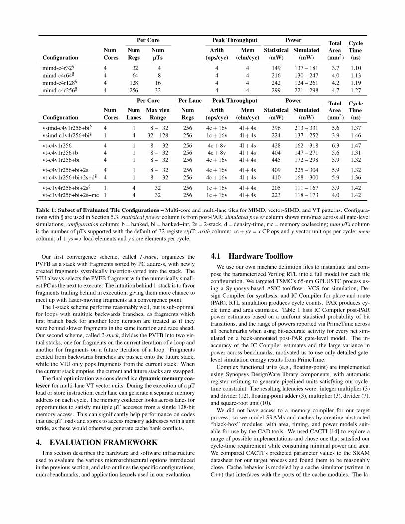
Per Core Peak Throughput Power TotalArea
CycleTimeNum Num Num Arith Mem Statistical Simulated
Configuration Cores Regs µTs (ops/cyc) (elm/cyc) (mW) (mW) (mm2) (ns)
mimd-c4r32§ 4 32 4 4 4 149 137 – 181 3.7 1.10mimd-c4r64§ 4 64 8 4 4 216 130 – 247 4.0 1.13mimd-c4r128§ 4 128 16 4 4 242 124 – 261 4.2 1.19mimd-c4r256§ 4 256 32 4 4 299 221 – 298 4.7 1.27
Per Core Per Lane Peak Throughput Power TotalArea
CycleTimeNum Num Max vlen Num Arith Mem Statistical Simulated
Configuration Cores Lanes Range Regs (ops/cyc) (elm/cyc) (mW) (mW) (mm2) (ns)
vsimd-c4v1r256+bi§ 4 1 8 – 32 256 4c + 16v 4l + 4s 396 213 – 331 5.6 1.37vsimd-c1v4r256+bi§ 1 4 32 – 128 256 1c + 16v 4l + 4s 224 137 – 252 3.9 1.46
vt-c4v1r256 4 1 8 – 32 256 4c + 8v 4l + 4s 428 162 – 318 6.3 1.47vt-c4v1r256+b 4 1 8 – 32 256 4c + 8v 4l + 4s 404 147 – 271 5.6 1.31vt-c4v1r256+bi 4 1 8 – 32 256 4c + 16v 4l + 4s 445 172 – 298 5.9 1.32
vt-c4v1r256+bi+2s 4 1 8 – 32 256 4c + 16v 4l + 4s 409 225 – 304 5.9 1.32vt-c4v1r256+bi+2s+d§ 4 1 8 – 32 256 4c + 16v 4l + 4s 410 168 – 300 5.9 1.36
vt-c1v4r256+bi+2s§ 1 4 32 256 1c + 16v 4l + 4s 205 111 – 167 3.9 1.42vt-c1v4r256+bi+2s+mc 1 4 32 256 1c + 16v 4l + 4s 223 118 – 173 4.0 1.42
Table 1: Subset of Evaluated Tile Configurations – Multi-core and multi-lane tiles for MIMD, vector-SIMD, and VT patterns. Configura-tions with § are used in Section 5.3. statistical power column is from post-PAR; simulated power column shows min/max across all gate-levelsimulations; configuration column: b = banked, bi = banked+int, 2s = 2-stack, d = density-time, mc = memory coalescing; num µTs columnis the number of µTs supported with the default of 32 registers/µT; arith column: xc + yv = x CP ops and y vector unit ops per cycle; memcolumn: xl + ys = x load elements and y store elements per cycle.
Our first convergence scheme, called 1-stack, organizes thePVFB as a stack with fragments sorted by PC address, with newlycreated fragments systolically insertion-sorted into the stack. TheVIU always selects the PVFB fragment with the numerically small-est PC as the next to execute. The intuition behind 1-stack is to favorfragments trailing behind in execution, giving them more chance tomeet up with faster-moving fragments at a convergence point.
The 1-stack scheme performs reasonably well, but is sub-optimalfor loops with multiple backwards branches, as fragments whichfirst branch back for another loop iteration are treated as if theywere behind slower fragments in the same iteration and race ahead.Our second scheme, called 2-stack, divides the PVFB into two vir-tual stacks, one for fragments on the current iteration of a loop andanother for fragments on a future iteration of a loop. Fragmentscreated from backwards branches are pushed onto the future stack,while the VIU only pops fragments from the current stack. Whenthe current stack empties, the current and future stacks are swapped.
The final optimization we considered is a dynamic memory coa-lescer for multi-lane VT vector units. During the execution of a µTload or store instruction, each lane can generate a separate memoryaddress on each cycle. The memory coalescer looks across lanes foropportunities to satisfy multiple µT accesses from a single 128-bitmemory access. This can significantly help performance on codesthat use µT loads and stores to access memory addresses with a unitstride, as these would otherwise generate cache bank conflicts.
4. EVALUATION FRAMEWORKThis section describes the hardware and software infrastructure
used to evaluate the various microarchitectural options introducedin the previous section, and also outlines the specific configurations,microbenchmarks, and application kernels used in our evaluation.
4.1 Hardware ToolflowWe use our own machine definition files to instantiate and com-
pose the parameterized Verilog RTL into a full model for each tileconfiguration. We targeted TSMC’s 65-nm GPLUSTC process us-ing a Synposys-based ASIC toolflow: VCS for simulation, De-sign Compiler for synthesis, and IC Compiler for place-and-route(PAR). RTL simulation produces cycle counts. PAR produces cy-cle time and area estimates. Table 1 lists IC Compiler post-PARpower estimates based on a uniform statistical probability of bittransitions, and the range of powers reported via PrimeTime acrossall benchmarks when using bit-accurate activity for every net sim-ulated on a back-annotated post-PAR gate-level model. The in-accuracy of the IC Compiler estimates and the large variance inpower across benchmarks, motivated us to use only detailed gate-level simulation energy results from PrimeTime.
Complex functional units (e.g., floating-point) are implementedusing Synopsys DesignWare library components, with automaticregister retiming to generate pipelined units satisfying our cycle-time constraint. The resulting latencies were: integer multiplier (3)and divider (12), floating-point adder (3), multiplier (3), divider (7),and square-root unit (10).
We did not have access to a memory compiler for our targetprocess, so we model SRAMs and caches by creating abstracted“black-box” modules, with area, timing, and power models suit-able for use by the CAD tools. We used CACTI [14] to explore arange of possible implementations and chose one that satisfied ourcycle-time requirement while consuming minimal power and area.We compared CACTI’s predicted parameter values to the SRAMdatasheet for our target process and found them to be reasonablyclose. Cache behavior is modeled by a cache simulator (written inC++) that interfaces with the ports of the cache modules. The la-
Control Thread Microthread Active µT Distribution (%)Name vf vec ld vec st int fp ld st amo br cmv tot loop nregs 1–25 26–50 51–75 76–100
µbm
arks
vvadd 1 2u 2u 1 2 4 100.0bsearch-cmv 1 1u 1u 17 2 1 4 25 ! 13 1.0 3.3 5.8 89.9bsearch 1 1u 1u 15 3 5 1 26 ! 10 77.6 12.4 5.1 4.8bsearch (w/ 1-stack) 23.8 23.4 11.7 41.0bsearch (w/ 2-stack) 10.1 26.8 49.2 13.9
App
Ker
nels
viterbi 3 3u 1u, 4s 21 3 35 8 100.0rsort 3 3u, 2s 3u 14 2 3 1 25 11 100.0kmeans 9 7u, 3s 5u, 1s 12 6 2 2 1 1 2 40 8 100.0dither 1 4u, 1s 5u, 1s 13 1 2 24 8 0.2 0.4 0.7 98.7physics 4 6u, 12s 1u, 9s 5 56 24 4 16 132 ! 32 6.9 15.0 28.7 49.3physics (w/ 2-stack) 4.7 13.1 28.3 53.9strsearch 3 5u 1u 35 9 5 15 2 96 ! 14 57.5 25.5 16.9 0.1strsearch (w/ 2-stack) 14.8 30.5 54.7 0.1
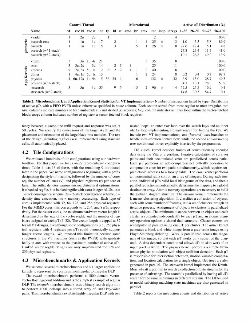
Table 2: Microbenchmark and Application Kernel Statistics for VT Implementation – Number of instructions listed by type. Distributionof active µTs with a FIFO PVFB unless otherwise specified in name column. Each section sorted from most regular to most irregular. vecld/st columns indicate numbers of both unit-stride (u) and strided (s) accesses; loop column indicates an inner loop within the vector-fetchedblock; nregs column indicates number of registers a vector-fetched block requires.
tency between a cache-line refill request and response was set at50 cycles. We specify the dimensions of the target ASIC and theplacement and orientation of the large black-box modules. The restof the design (including regfiles) was implemented using standardcells, all automatically placed.
4.2 Tile ConfigurationsWe evaluated hundreds of tile configurations using our hardware
toolflow. For this paper, we focus on 22 representative configura-tions; Table 1 lists 13 of these, with the remaining 9 introducedlater in the paper. We name configurations beginning with a prefixdesignating the style of machine, followed by the number of cores(c), the number of lanes (v), and physical registers (r) per core orlane. The suffix denotes various microarchitectural optimizations:b = banked regfile, bi = banked regfile with extra integer ALUs, 1s =1-stack convergence scheme, 2s = 2-stack convergence scheme, d =density-time execution, mc = memory coalescing. Each type ofcore is implemented with 32, 64, 128, and 256 physical registers.For the MIMD cores, this corresponds to 1, 2, 4, and 8 µTs respec-tively. For the vector cores, the maximum hardware vector length isdetermined by the size of the vector regfile and the number of reg-isters assigned to each µT (4–32). The vector length is capped at 32for all VT designs, even though some configurations (i.e., 256 phys-ical registers with 4 registers per µT) could theoretically supportlonger vector lengths. We imposed this limitation because somestructures in the VT machines (such as the PVFB) scale quadrat-ically in area with respect to the maximum number of active µTs.Banked vector regfile designs are only implemented for 128 and256 physical registers.
4.3 Microbenchmarks & Application KernelsWe selected several microbenchmarks and six larger application
kernels to represent the spectrum from regular to irregular DLP.The vvadd microbenchmark performs a 1000-element vector-
vector floating-point addition and is the simplest example of regularDLP. The bsearch microbenchmark uses a binary search algorithmto perform 1000 look-ups into a sorted array of 1000 key-valuepairs. This microbenchmark exhibits highly irregular DLP with two
nested loops: an outer for loop over the search keys and an innerwhile loop implementing a binary search for finding the key. Weinclude two VT implementations: one (bsearch) uses branches tohandle intra-iteration control flow, while the second (bsearch-cmv)uses conditional moves explicitly inserted by the programmer.
The viterbi kernel decodes frames of convolutionally encodeddata using the Viterbi algorithm. Iterative calculation of survivorpaths and their accumulated error are parallelized across paths.Each µT performs an add-compare-select butterfly operation tocompute the error for two paths simultaneously, which requires un-predictable accesses to a lookup table. The rsort kernel performsan incremental radix sort on an array of integers. During each iter-ation, individual µTs build local histograms of the data, and then aparallel reduction is performed to determine the mapping to a globaldestination array. Atomic memory operations are necessary to buildthe global histogram structure. The kmeans kernel implements thek-means clustering algorithm. It classifies a collection of objects,each with some number of features, into a set of clusters through aniterative process. Assignment of objects to clusters is parallelizedacross objects. The minimum distance between an object and eachcluster is computed independently by each µT and an atomic mem-ory operation updates a shared data structure. Cluster centers arerecomputed in parallel using one µT per cluster. The dither kernelgenerates a black and white image from a gray-scale image usingFloyd-Steinberg dithering. Work is parallelized across the diago-nals of the image, so that each µT works on a subset of the diag-onal. A data-dependent conditional allows µTs to skip work if aninput pixel is white. The physics kernel performs a simple New-tonian physics simulation with object collision detection. Each µTis responsible for intersection detection, motion variable computa-tion, and location calculation for a single object. Oct-trees are alsogenerated in parallel. The strsearch kernel implements the Knuth-Morris-Pratt algorithm to search a collection of byte streams for thepresence of substrings. The search is parallelized by having all µTssearch for the same substrings in different streams. The DFAs usedto model substring-matching state machines are also generated inparallel.
Table 2 reports the instruction counts and distribution of active

1 void idlp( int c[], int a[], int b[], int n, int x ) {2 int vlen = vt::config( 7, n ); // config vector unit3 vt::HardwareVector<int> vx(x);4 for ( int i = 0; i < n; i += vlen ) {5 vlen = vt::set_vlen(n-i); // stripmining6
7 vt::HardwareVector<int*> vcptr(&c[i]);8 vt::HardwareVector<int> va, vb;9 va.load(&a[i]); // unit-stride vector load
10 vb.load(&b[i]); // unit-stride vector load11
12 VT_VFETCH( (vcptr,vx,va,vb), ({13 if ( va > 0 )14 vcptr[vt::get_utidx()] = vx * va + vb;15 }));16 }17 vt::sync_cv(); // vector memory fence18 }
Figure 6: Irregular DLP Example Using VT C++ Library –Code for loop in Figure 1(d). Roughly compiles to assembly inFigure 3(d). config() specifies number of required µT registers.set_vlen() sets number of active µTs. get_utidx() returns µT’sthread index. HardwareVector<T> type enables moving data inand out of vector registers; compiler handles vector register allo-cation. VT_VFETCH macro expands to vector fetch for given codeblock. HardwareVector<T> objects act as vectors outside blockand as scalars inside block. Any valid C++ is allowed inside avector-fetched block excluding system calls and exceptions.
µTs for the VT implementations of two representative microbench-marks and the six application kernels. viterbi is an example of reg-ular DLP with known memory access patterns. rsort, kmeans, anddither all exhibit mild control flow conditionals with more irregularmemory access patterns. physics and strsearch exhibits character-istics of highly irregular DLP code: loops with data-dependent exitconditionals, highly irregular data access patterns, and many condi-tional branches.
4.4 Programming MethodologyPast accelerators usually relied on hand-coded assembly or com-
pilers that automatically extract DLP from high-level programminglanguages [1,4,7]. Recently there has been a renewed interest in ex-plicitly data-parallel programming methodologies [3,15,17], wherethe programmer writes code for the HT and annotates data-paralleltasks to be executed in parallel on all µTs. We developed a sim-ilar explicit-DLP C++ programming environment for Maven. Wemodified the GNU C++/newlib toolchain to generate code for theunified ISA used on both CT and µTs, and also developed a VTlibrary to manage the interaction between the two types of thread(see Figure 6).
For vector-SIMD, we were able to leverage the built-in GCC vec-torizer for mapping very simple regular DLP microbenchmarks, butthe GCC vectorizer cannot automatically compile the larger appli-cation kernels for the vector-SIMD tiles. For these more compli-cated vector-SIMD kernels, we use a subset of our VT C++ libraryfor stripmining and vector memory operations along with GCC’sinline assembly extensions for the actual computation. We used avery similar vectorization approach as in the VT implementations,but the level of programmer effort required for vector-SIMD wassubstantially higher. Our struggle to find a suitable way to programmore interesting codes for the vector-SIMD pattern is anecdotal ev-idence of the broader challenge of programming such accelerators,
and this helped motivate our interest in the VT programming model.MIMD code is written using a custom lightweight threading li-
brary, and applications explicitly manage thread scheduling. For allsystems, a simple proxy kernel running on the cores supports basicsystem calls by communicating with an application server runningon the host.
5. EVALUATION RESULTSIn this section, we first compare tile configurations based on their
cycle time and area before exploring the impact of various microar-chitectural optimizations. We then compare implementation effi-ciency and performance of the MIMD, vector-SIMD, and VT pat-terns for the six application kernels. We present highlights from ourresults here; more extensive results are available separately [11].
5.1 Cycle Time and Area ComparisonTile cycle times vary from 1.10–1.47 ns (see Table 1), with criti-
cal paths usually passing through the crossbar that connects cores toindividual data cache banks. Figure 7(a) shows the area breakdownof the tiles normalized to a mimd-c4r32 tile. The caches contributethe most to the area of each tile. Note that a multi-core vector-SIMDtile (vsimd-c4v1r256+bi) is 20% larger than a multi-core MIMDtile with the same number of long-latency functional units and thesame total number of physical registers (mimd-c4r256) due to thesophisticated VMU and the extra integer ALUs per bank. A multi-lane vector-SIMD tile (vsimd-c1v4r256+bi) is actually 16% smallerthan the mimd-c4r256 tile because the increased area overheads areamortized across four lanes. Note that we added additional bufferspace to the multi-lane tiles to balance the performance across vec-tor tiles, resulting in similar area usage of the memory unit for bothmulti-core and multi-lane vector tiles. Across all vector tiles, theoverhead of the embedded control processor is less than 5%, sinceit shares long-latency functional units with the vector unit.
Comparing a multi-core VT tile (vt-c4v1r256+bi) to a multi-corevector-SIMD tile (vsimd-c4v1r256+bi) shows the area overhead ofthe extra VT mechanisms is only "6%. The VT tile includes aPVFB instead of a vector flag regfile, causing the regfile area todecrease and the control area to increase. There is also a small areaoverhead due to the extra VT instruction cache. For multi-lane tiles,these VT overheads are amortized across four lanes making themnegligible (compare vt-c1v4r256+bi+2s vs. vsimd-c1v4r256+bi).
5.2 Microarchitectural TradeoffsFigure 8 shows the impact of increasing the number of phys-
ical registers per core or lane when executing bsearch-cmv. Formimd-c4r*, increasing the number of µTs from 1 to 2 improvesperformance but at an energy cost. The energy increase is due to alarger regfile (now 64 registers per core) and more control overhead.Supporting more than two µTs reduces performance due to the non-trivial start-up overhead required to spawn and join the additionalµTs and a longer cycle time. In the vt-c4v1 tile with a unified vectorregfile, adding more vector register elements increases hardwarevector length and improves temporal amortization of the CP, in-struction cache, and control energy. At 256 registers, however, thelarger access energy of the unified regfile outweighs the benefits ofincreased vector length. The performance also decreases since theaccess time of the regfile becomes critical.
Figure 8 also shows the impact of regfile banking and adding per-bank integer ALUs. Banking a regfile with 128 entries reduces reg-file access energy but decreases performance due to bank conflicts

mimd-c4 vsimd+bi
vt-c4v1 vt-c4v1+bi
vt-c1v4+bi+2s
r32r64r128r256
c1v4r256c4v1r256
r32r64r128r256r128+br256+br128+bir256+bi
r256r256+dr256+1sr256+1s+dr256+2sr256+2s+d
r256r256+m
c
0.00
0.25
0.50
0.75
1.00
1.25
1.50
1.75N
orm
aliz
edA
rea
ctrlregmemfp
intcpi$d$
(a) Area Breakdown for Evaluated Tile Configurations (b) ASIC Layout forvt-c4v1r256+bi+2s+d
Figure 7: Area and VLSI Layout for Tile Configurations – (a) area breakdown for each of the 22 tile configurations normalized to themimd-c4r32 tile, (b) ASIC layout for vt-c4v1r256+bi+2s+d with individual cores and memory crossbar highlighted.
0.8 1.0 1.2 1.4 1.6 1.8 2.0 2.2 2.4 2.6Normalized Tasks / Sec
0.40.50.60.70.80.91.01.11.21.31.41.51.6
Nor
mal
ized
Ener
gy/T
ask
r32
r64
r128
r256
r32
r64 r128
r256r128 r256 r128 r256
mimd-c4vt-c4v1vt-c4v1+bvt-c4v1+bi
mimd-c4 vt-c4v1 vt-c4v1+b vt-c4v1+bi
r32r64r128r256
r32r64r128r256
r128r256
r128r256
0
5
10
15
20
25
30
Ener
gy/T
ask
(uJ)
ctrlregmemfpint
cpi$d$leak
(a) Energy vs. Performance for bsearch-cmv (b) Energy Breakdown for bsearch-cmv
Figure 8: Impact of Additional Physical Registers, Intra-Lane Regfile Banking, and Additional Per-Bank Integer ALUs – Results formulti-core MIMD and VT tiles running the bsearch-cmv microbenchmark.
(see vt-c4v1+b configuration). Adding per-bank integer ALUs par-tially offsets this performance loss (see vt-c4v1+bi configuration).With the additional ALUs, a VT tile with a banked regfile improvesboth performance and energy versus a VT tile with a unified regfile.Figure 7(a) shows that banking the vector regfile reduces the regfilearea by a factor of 2!, while adding local integer ALUs in a bankeddesign only modestly increases the integer and control logic area.Based on analyzing results across many tile configurations and ap-plications, we determined that banking the vector regfile and addingper-bank integer ALUs was the optimal choice for all vector tiles.
Figure 9 shows the impact of adding density-time execution anddynamic fragment convergence to a multi-core VT tile runningbsearch. Adding just density-time execution eliminates significantwasted work after divergence, improving performance by 2.5! andreducing energy by 2!. Density-time execution is less useful onmulti-lane configurations due to the additional constraints requiredfor compression. Our stack-based convergence schemes are a dif-ferent way of mitigating divergence by converging µTs when pos-sible. For bsearch, the 2-stack PVFB forces µTs to stay on thesame loop iteration, improving performance by 6! and reducing
2.0 4.0 6.0 8.0 10.0 12.0 14.0Normalized Tasks / Sec
0.00.10.20.30.40.50.60.70.80.91.0
Nor
mal
ized
Ener
gy/T
ask FIFO
FIFO+dt
1-stack1-stack+dt 2-stack
2-stack+dtcmv
+FIFO
cmv+2-stack+dt
Figure 9: Impact of Density-Time Execution and Stack-BasedConvergence Schemes – Results for multi-core VT tile runningbsearch and bsearch-cmv.
energy by 5! as compared to the baseline FIFO PVFB. Combin-ing density-time and a 2-stack PVFB has little impact here as the2-stack scheme already removes most divergence (see Table 2).Our experience with other microbenchmarks and application ker-

0.1 0.2 0.3 0.4 0.5 0.6 0.7 0.8 0.9 1.0Normalized Tasks / Sec
1
2
3
4
5
6N
orm
aliz
edEn
ergy
/Tas
k
vec ld/st
uT ld/st
uT ld/st + mem coalescing
Figure 10: Impact of Memory Coalescing – Results for multi-lane VT tile running vvadd.
nels suggest that for codes where convergence is simply not possi-ble the addition of density-time execution can have significant im-pact. Note that replacing branches with explicit conditional moves(bsearch-cmv) performs better than dynamic optimizations for µTbranches, but µT branches are more general and simpler to programfor irregular DLP codes. Table 1 and Figure 7(a) show that the 2-stack PVFB and density-time execution have little impact on areaand cycle time. Based on our analysis, the 2-stack PVFB is usedfor both multi-core and multi-lane VT tiles, while density-time ex-ecution is only used on multi-core VT tiles.
Figure 10 illustrates the benefit of vector memory accesses ver-sus µT memory accesses on a multi-lane VT tile running vvadd.Using µT memory accesses limits opportunities for access-executedecoupling and requires six additional µT instructions for addressgeneration, resulting in over 5!worse energy and 7!worse perfor-mance for vvadd. Memory coalescing recoups some of the lost per-formance and energy efficiency, but is still far behind vector instruc-tions. This small example hints at key differences between SIMTand VT. Current SIMT implementations use a very large number ofµTs (and large regfiles) to hide memory latency instead of a decou-pled control thread, and rely on dynamic coalescing instead of truevector memory instructions. However, exploiting these VT featuresrequires software to factor out the common work from the µTs.
5.3 Application Kernel ResultsFigure 11 compares the application kernel results between the
MIMD, vector-SIMD, and VT tiles. The upper row plots over-all energy/task against performance, while the lower row plots en-ergy/task against area-normalized performance to indicate expectedthroughput from a given silicon budget for a highly parallel work-load. Kernels are ordered to have increasing irregularity from leftto right. We draw several broad insights from these results.
First, we observed that adding more µTs to a multi-core MIMDtile is not particularly effective, especially when area is considered.We found parallelization and load-balancing become more chal-lenging for the complex application kernels, and adding µTs canhurt performance in some cases due to increased cycle time andnon-trivial interactions with the memory system.
Second, we observed that the best vector-based machines aregenerally faster and/or more energy-efficient than the MIMD coresthough normalizing for area reduces the relative advantage, and forsome irregular codes the MIMD cores perform slightly better (e.g.,strsearch) though at a greater energy cost.
Third, comparing vector-SIMD and VT on the first four kernels,we see VT is more efficient than vector-SIMD for both multi-core
single-lane (c4v1) and single-core multi-lane (c1v4) design points.Note we used hand-optimized vector-SIMD code but compiled VTcode for these four kernels. One reason VT performs better thanvector-SIMD, particularly on multi-lane viterbi and kmeans, is thatvector-fetch instructions more compactly encode work than vectorinstructions, reducing pressure on the VIU queue and allowing theCT to run ahead faster.
Fourth, comparing c4v1 versus c1v4 vector machines, we see thatthe multi-lane vector designs are generally more energy-efficientthan multi-core vector designs as they amortize control overheadover more datapaths. Another advantage we observed for multi-lane machines was that we did not have to partition and load-balance work across multiple cores. Multi-core vector machinessometimes have a raw performance advantage over multi-lane vec-tor machines. Our multi-lane tiles have less address bandwidth tothe shared data cache, making code with many vector loads andstores perform worse (kmeans and physics). Lack of density-timeexecution and no ability to run independent control threads alsoreduces efficiency of multi-lane machines on irregular DLP code.However, these performance advantages for multi-core vector ma-chines usually disappear once area is considered, except for themost irregular kernel strsearch. The area difference is mostly dueto the disparity in aggregate instruction cache capacity.
Overall, our results suggest a single-core multi-lane VT tile withthe 2-stack PVFB and a banked regfile with per-bank integer ALUs(vt-c1v4r256+bi+2s) is a good design point for Maven.
6. CONCLUSIONSEffective data-parallel accelerators must handle regular and ir-
regular DLP efficiently and still retain programmability. Our de-tailed VLSI results confirm that vector-based microarchitecturesare more area and energy efficient than scalar-based microarchitec-tures, even for fairly irregular data-level parallelism. We introducedMaven, a new simpler vector-thread microarchitecture based on thetraditional vector-SIMD microarchitecture, and showed that it is su-perior to traditional vector-SIMD architectures by providing bothgreater efficiency and easier programmability. Maven’s efficiencyis improved with several new microarchitectural optimizations, in-cluding efficient dynamic convergence for microthreads and ALUsdistributed close to the banks within a banked vector register file.
In future work, we are interested in a more detailed comparisonof VT to the popular SIMT design pattern. Our initial results sug-gest that SIMT will be less efficient though easier to program thanVT. We are also interested in exploring whether programming en-vironment improvements can simplify the programming of vector-SIMD machines to reduce the need for VT or SIMT mechanisms,and whether hybrid machines containing both pure MIMD and pureSIMD might be more efficient than attempting to execute very ir-regular code on SIMD hardware.
ACKNOWLEDGMENTSThis work was supported in part by Microsoft (Award #024263)
and Intel (Award #024894, equipment donations) funding and bymatching funding from U.C. Discovery (Award #DIG07-10227).The authors acknowledge and thank Jiongjia Fang and Ji Kim fortheir help writing application kernels, Christopher Celio for his helpwriting Maven software and developing the vector-SIMD instruc-tion set, and Hidetaka Aoki for his early feedback on the Mavenmicroarchitecture.

0.5 1.0 1.50.0
0.5
1.0
1.5
2.0
Nor
mal
ized
Ener
gy/T
ask
r32
mlane
mcore
0.5 1.0 1.5
r32
mlane
mcore
1.0 2.0 3.0
r32
mlane
mcore
0.5 1.0 1.5 2.0 2.5
r32
mlane
mcore
0.5 1.0 1.5 2.0
r32
mlane
mcore
0.5 1.0 1.5
r32
mlanemcore
Normalized Tasks / Second
0.5 1.0 1.50.0
0.5
1.0
1.5
2.0
Nor
mal
ized
Ener
gy/T
ask
r32
mlane
mcore
0.5 1.0 1.5
r32
mlane
mcore
1.0 2.0 3.0
r32 mcore/mlane
0.5 1.0 1.5 2.0 2.5
r32
mlane
mcore
0.5 1.0 1.5 2.0
r32
mlane
mcore
0.5 1.0 1.5
r32mlane
mcore
Normalized Tasks / Second / Area(a) viterbi (b) rsort (c) kmeans (d) dither (e) physics (f) strsearch
Figure 11: Implementation Efficiency and Performance for MIMD, vector-SIMD, and VT Patterns Running Application Kernels –Each column is for different kernel. Legend at top. mimd-c4r256 is significantly worse and lies outside the axes for some graphs. There areno vector-SIMD implementations for strsearch and physics due to difficulty of implementing complex irregular DLP in hand-coded assembly.mcore = multi-core vector-SIMD/VT tiles, mlane = multi-lane vector-SIMD/VT tiles, r32 = MIMD tile with 32 registers (i.e., one µT).
REFERENCES[1] D. F. Bacon et al. Compiler Transformations for
High-Performance Computing. ACM Computing Surveys,26(4):345–420, Dec 1994.
[2] C. Batten. Simplified Vector-Thread Architectures forFlexible and Efficient Data-Parallel Accelerators. PhDThesis, MIT, 2010.
[3] I. Buck et al. Brook for GPUs: Stream Computing onGraphics Hardware. ACM Transactions on Graphics,23(3):777–786, Aug 2004.
[4] D. DeVries and C. G. Lee. A Vectorizing SUIF Compiler.SUIF Compiler Workshop, Jan 1995.
[5] R. Espasa and M. Valero. Decoupled Vector Architectures.HPCA, Feb 1996.
[6] M. Gschwind et al. Synergistic Processing in Cell’sMulticore Architecture. IEEE Micro, 26(2):10–24, Mar 2006.
[7] M. Hampton and K. Asanovic. Compiling for Vector-ThreadArchitectures. CGO, Apr 2008.
[8] J. H. Kelm et al. Rigel: An Architecture and ScalableProgramming Interface for a 1000-core Accelerator. ISCA,Jun 2009.
[9] R. Krashinsky. Vector-Thread Architecture andImplementation. PhD Thesis, MIT, 2007.
[10] R. Krashinsky et al. The Vector-Thread Architecture. ISCA,Jun 2004.
[11] Y. Lee. Efficient VLSI Implementations of Vector-ThreadArchitectures. MS Thesis, UC Berkeley, 2011.
[12] E. Lindholm et al. NVIDIA Tesla: A Unified Graphics andComputer Architecture. IEEE Micro, 28(2):39–55, Mar/Apr2008.
[13] A. Mahesri et al. Tradeoffs in Designing AcceleratorArchitectures for Visual Computing. MICRO, Nov 2008.
[14] N. Muralimanohar et al. CACTI 6.0: A Tool to Model LargeCaches, 2009.
[15] J. Nickolls et al. Scalable Parallel Programming with CUDA.ACM Queue, 6(2):40–53, Mar/Apr 2008.
[16] NVIDIA’s Next Gen CUDA Compute Architecture: Fermi.NVIDIA White Paper, 2009.
[17] The OpenCL Specification. Khronos OpenCL WorkingGroup, 2008.
[18] S. Rivoire et al. Vector Lane Threading. Int’l Conf. onParallel Processing, Aug 2006.
[19] R. M. Russel. The Cray-1 Computer System.Communications of the ACM, 21(1):63–72, Jan 1978.
[20] K. Sankaralingam et al. Universal Mechanisms forData-Parallel Architectures. MICRO, Dec 2003.
[21] J. Smith et al. Vector Instruction Set Support for ConditionalOperations. ISCA, Jun 2000.
[22] J. Wawrzynek et al. Spert-II: A Vector MicroprocessorSystem. IEEE Computer, 29(3):79–86, Mar 1996.