EXPLORATION FOR MASSIVE SULPHIDES IN DESERT AREAS … · 37. EXPLORATION FOR MASSIVE SULPHIDES IN...
12
37. EXPLORATION FOR MASSIVE SULPHIDES IN DESERT AREAS USING THE GROUND PULSE ELECTROMAGNETIC METHOD Duncan Crone Crone Geophysics Limited, Mississauga, Ontario Crone, Duncan, Exploration for massive sulphides in desert areas using the ground pulse electromagnetic method; in Geophysics and Geochemistry in the Search for Metallic Ores; Peter J. Hood, editor; GeologiCal Survey of Canada, Economic Geology Report 31, p. 715-755, 1979. Abstract Examples of ground Pulse electromagnetic surveys from Arizona, the Sultanate of Oman, and Aust.ralia, show that both massive and fracture-filling sulphide bodies can be detected in desert conditions. The wide frequency spectrum of Pulse EM equipment,and its capability of defining the shape of the conductor, enable the method to differentiate between oxidized sulphides and conductive surficial layers. even though the conductivity contrast is slight. It is important for exploration purposes to retain the high frequency portion of the Pulse electromagnetic spectrum. Low sulphide content marker horizons and narrow oxidized sulphide zones are usually detectable only at high frequencies. New detailed and deep penetration methods utilizing the ground Pulse EM are being developed to locate accurately the position of the sulphide body; as exploration methods reach greater depths of penetration, this becomes increasingly important. Borehole Pulse electromagnetic equipment has been built that will detect sulphide bodies 100 m to the side of a borehole. The capabilities of Borehole Pulse EM surveys in detecting and defining the position of sulphide bodies, should encourage deep exploration in the vicinity of known mineral deposits. Resume Les exemples d'etudes elecuomagnetiques au sol en Arizona, dans Ie Sultana!. d'Oman et en Aus!.ralie, montrent que les corps sulfures massifs et ceux remplissant les fractures peuvent etre deceles dans les milieux desertiques. La vaste gamme de frequences de l'appareillage et la capacite de celui-ci a definir la forme du conducteur, permettent de distinguer les sUlfures oxydes des couches superficielles conductrices, meme quand Ie contraste de conductivite est faible. II est important pour l'exploration de garder seulement la gamme de hautes frequences. Les horizons reperes a faible taux de sulfures et les etroites zones de sulfures oxydes sont normale men I. detectes seule ment aux hautes frequences. On a mis au point de nouvelles methodes detaillees, de prospection profonde utilisant les ondes electromagnetiques au sol, qui permettent de localiser avec plus de precision les minerais sulfures; cet aspect de la prospection prend de l'importance, d mesure que les methodes d'exploration permettent une exploration plus profonde du sous-sol. On a construit un appareil de prospection EM utilise dans les forages. pour reperer les minerais sulfures dans un rayon de 100 m a partir du sondage. Les possibilites offertes par la methode de leves EM a partir de forages pour deceler et delimiter les sulfures, devraient encourager l'exploration profonde d proximite des gites mineraux connus. EXPLORATION OBJECTIVES AND PROBLEMS ENCOUNTERED IN DESERT AREAS A ground geophysical survey for mineral exploration normally has three specific objectives: to locate an airborne electromagnetic anomaly on the ground, or to discover an anomaly that could be an orebody; to provide sufficient information to permit an evaluation of the anomaly in comparison with other anomalies; to obtain results that allow determination of the dip, depth and width of the target with sufficient accuracy to position an exploration drillhole. When an exploration program for massive sulphide deposits is carried out in a desert region, attaining these objectives becomes increasingly difficult. The primary difficulty is surface weathering that gradually reduces the conducting sulphides to resistive oxides. This is a highly variable process whose effect may range from a few metres to 200 metres in depth from surface. The oxidation weathering process also tends to break down the inter-crystal electronic connection within a sulphide body. The presence of even minor oxidation can drastically reduce the conductivity of a massive sulphide body. Targets in desert areas are therefore usually deeper and are weaker conductors than those encountered in unweathered areas. The desert climate also produces large areas of high surficial conductivity that may consist of brackish groundwater or conductive rock formations such as conglomerates or limestones. This surficial conductivity reduces the penetration of electrical and electromagnetic (EM) methods and creates a background of confusing spurious anomalies. Induced polarization has traditionally been the most effecti ve geophysical method in the exploration for sulphides in desert areas. The method is suited primarily for the detection of large disseminated deposits, but it is not effective in the exploration for smaller, massive sulphide bodies (Dolan, 1967). Most conventional EM systems have been designed for use in resistive environments and can be usefully applied, only in nonconductive desert areas. Thus suitable ground geophysical equipment that would be effective in the search for massive sulphides in desert areas has, in the past, not been available. DEVELOPMENT OF THE GROUND PULSE EM METHOD The Pulse EM system was selected by Crone Geophysics Ltd. as an exploration tool since it appeared to have the most likely capability of providing conductivity, depth, dip and width information for subsurface conductors. The wide frequency spectrum of measurement of a Pulse EM system is capable of resolving the variance of conductivity encountered under desert conditions, and the low frequency portion of the spectrum can penetrate through the surficial conductive layer. Crone Geophysics Limited initiated a Pulse EM
Transcript of EXPLORATION FOR MASSIVE SULPHIDES IN DESERT AREAS … · 37. EXPLORATION FOR MASSIVE SULPHIDES IN...

37. EXPLORATION FOR MASSIVE SULPHIDES IN DESERT AREASUSING THE GROUND PULSE ELECTROMAGNETIC METHOD
Duncan CroneCrone Geophysics Limited, Mississauga, Ontario
Crone, Duncan, Exploration for massive sulphides in desert areas using the ground pulseelectromagnetic method; in Geophysics and Geochemistry in the Search for Metallic Ores;Peter J. Hood, editor; GeologiCal Survey of Canada, Economic Geology Report 31, p. 715-755, 1979.
Abstract
Examples of ground Pulse electromagnetic surveys from Arizona, the Sultanate of Oman, andAust.ralia, show that both massive and fracture-filling sulphide bodies can be detected in desertconditions. The wide frequency spectrum of Pulse EM equipment,and its capability of defining theshape of the conductor, enable the method to differentiate between oxidized sulphides and conductivesurficial layers. even though the conductivity contrast is slight. It is important for exploration purposesto retain the high frequency portion of the Pulse electromagnetic spectrum. Low sulphide contentmarker horizons and narrow oxidized sulphide zones are usually detectable only at high frequencies.New detailed and deep penetration methods utilizing the ground Pulse EM are being developed tolocate accurately the position of the sulphide body; as exploration methods reach greater depths ofpenetration, this becomes increasingly important. Borehole Pulse electromagnetic equipment has beenbuilt that will detect sulphide bodies 100 m to the side of a borehole. The capabilities of BoreholePulse EM surveys in detecting and defining the position of sulphide bodies, should encourage deepexploration in the vicinity of known mineral deposits.
Resume
Les exemples d'etudes elecuomagnetiques au sol en Arizona, dans Ie Sultana!. d'Oman et enAus!.ralie, montrent que les corps sulfures massifs et ceux remplissant les fractures peuvent etredeceles dans les milieux desertiques. La vaste gamme de frequences de l'appareillage et la capacite decelui-ci a definir la forme du conducteur, permettent de distinguer les sUlfures oxydes des couchessuperficielles conductrices, meme quand Ie contraste de conductivite est faible. II est important pourl'exploration de garder seulement la gamme de hautes frequences. Les horizons reperes a faible taux desulfures et les etroites zones de sulfures oxydes sont normale men I. detectes seule ment aux hautesfrequences. On a mis au point de nouvelles methodes detaillees, de prospection profonde utilisant lesondes electromagnetiques au sol, qui permettent de localiser avec plus de precision les mineraissulfures; cet aspect de la prospection prend de l'importance, d mesure que les methodes d'explorationpermettent une exploration plus profonde du sous-sol. On a construit un appareil de prospection EMutilise dans les forages. pour reperer les minerais sulfures dans un rayon de 100 m a partir du sondage.Les possibilites offertes par la methode de leves EM a partir de forages pour deceler et delimiter lessulfures, devraient encourager l'exploration profonde d proximite des gites mineraux connus.
EXPLORATION OBJECTIVES AND PROBLEMSENCOUNTERED IN DESERT AREAS
A ground geophysical survey for mineral explorationnormally has three specific objectives:
to locate an airborne electromagnetic anomaly on theground, or to discover an anomaly that could be anorebody;
to provide sufficient information to permit an evaluationof the anomaly in comparison with other anomalies;
to obtain results that allow determination of the dip,depth and width of the target with sufficient accuracy toposition an exploration drillhole.
When an exploration program for massive sulphide deposits iscarried out in a desert region, attaining these objectivesbecomes increasingly difficult. The primary difficulty issurface weathering that gradually reduces the conductingsulphides to resistive oxides. This is a highly variable processwhose effect may range from a few metres to 200 metres indepth from surface. The oxidation weathering process alsotends to break down the inter-crystal electronic connectionwithin a sulphide body. The presence of even minor oxidationcan drastically reduce the conductivity of a massive sulphidebody. Targets in desert areas are therefore usually deeper andare weaker conductors than those encountered inunweathered areas. The desert climate also produces largeareas of high surficial conductivity that may consist of
brackish groundwater or conductive rock formations such asconglomerates or limestones. This surficial conductivityreduces the penetration of electrical and electromagnetic(EM) methods and creates a background of confusing spuriousanomalies.
Induced polarization has traditionally been the mosteffecti ve geophysical method in the exploration for sulphidesin desert areas. The method is suited primarily for thedetection of large disseminated deposits, but it is noteffective in the exploration for smaller, massive sulphidebodies (Dolan, 1967). Most conventional EM systems havebeen designed for use in resistive environments and can beusefully applied, only in nonconductive desert areas. Thussuitable ground geophysical equipment that would beeffective in the search for massive sulphides in desert areashas, in the past, not been available.
DEVELOPMENT OF THE GROUND PULSE EM METHOD
The Pulse EM system was selected by Crone GeophysicsLtd. as an exploration tool since it appeared to have the mostlikely capability of providing conductivity, depth, dip andwidth information for subsurface conductors. The widefrequency spectrum of measurement of a Pulse EM system iscapable of resolving the variance of conductivity encounteredunder desert conditions, and the low frequency portion of thespectrum can penetrate through the surficial conductivelayer. Crone Geophysics Limited initiated a Pulse EM

746 Duncan Crone
development program in 1972 with the co-operation ofNewmont Mining Corporation. Newmont held the originalPulse EM patents (Wait, 1956) and had developed a largePulse EM instrument which had been used successfully inCyprus (Dolan, 1967). The Crone equipment (Crone, 1975)consists of a moving horizontal loop system; two personsoperate the transmitter and one the receiver. Thetransmitter-receiver coil separation is 50 to 150 m. Thetransmitter is a multiturn loop of wire 6 to 15 m in diameterlaid out in a rough circle on the ground. The currentwaveform is 10.8 ms on, 10.8 ms off with a 1.4 ms rampshut-off. Eight delay time-windows, or channels, of thesecondary field are sampled after the current shut-off at0.15, 0.30, 0.55, 0.90, 1.45, 2.40, 4.00, and 6.40. milliseconqsto the centre of the sample. The sample amplitude isnormalized by setting to 1000, a sample taken of themaximum shut-off vOltage amplitude measured at thereceiver. The sample measurements are therefore withoutdimensions. The first sample (0.15 ms) is in units of 1/1000of the shut-off sample, the eighth sample in units of1/10 000 of the shut-off sample, with a logarithmicdispersion in between. Unlike conventional horizontal loopEM surveys variance in coil separation and elevation effectsare not critical with this time domain method.
LINE 2 +oos
, ------+-------+-----GOSSAN
ZONE
PULSE E.M.50 METER COil SPACING
'0
20 6==~~~~_ ......~-~""==='"---+~="'37~'~MS~
10 7 ------
o ,-=---...-.q---.=:===-~~-......-4__-"'=~;;;;.1
'00
3E
I2E
I
0·1 % to 0·2 % CuDISSEMINATEDSULPHIDES
.~.COilS
"IBL
I
-200
-50
-150
-0
"..... -100~~
IW
I
<Jt = 2-5 MHOS
50 100 METERS10
100
WEATHERED
MASSIVE ISULPHIDES/ /
20
30
4050
200
(",0'1TAW I RAKAH - LINE 400N o
Figure 37.1. Pulse EM profile, 50 m coil spacing, movingcoils method, Ghayth showing, Sultanate of Oman.
Figure 37.2. Pulse EM profile, 100 m coil spacing, movingcoils method, Tawi Rakah, Sultanate of Oman.
Field Examples of Ground Pulse EM Surveys ofPoor Conductors
The following are case histories and recentdevelopments in the application of a ground Pulseelectromagnetic system designed for exploration in desertareas. Figure 37.1 is a typical example of the response froma narrow (width less than 3 m), weathered, massive sulphidezone using the Crone Pulse EM technique. This profile wasobtained over the Ghayth copper-zinc showing in theSultanate of Oman. Narrow, massive sulphide zones such AS
this tend to weather to considerable depths. This zone istherefore a poor conductor and is detected by the first PulseEM sample only. Figure 37.2, also from the Sultanate ofOman, represents the type of anomaly obtained from a zoneof disseminated sulphides. In this case, the weathering isshallow (only 30 m), with the lack of conductivity beingcaused by a low sulphide content of approximately5 per cent. The important factor illustrated by these twoexamples is the necessity of retaining the high frequencyinformation generated by a Pulse EM system. Thisinformation enables the operator to detect and trace outnarrow or weakly mineralized zones that are favourablegeological horizons. These zones may expand into larger,more massive bodies along strike.
The conducti vity-thickness (ot) of these sulphide zonesoften is the same order as that of the conductive surficiallayer. The sUlphide zone is detected only because of thegeometrical presence of both vertical and horizontalconductive sheets. The importance of detecting weakconductors is illustrated in Figure 37.3, which shows thediscovery Pulse EM profile over the Bayda copper-zincorebody in Oman. The Bayda showing consisted of an ancientexploratory pit in a smull gossan zone at the side of a hill.This showing produces a weak two-sample anomaly that wastraced downhill until it strengthened to a six-sampleanomaly on line 1+00N. Drilling this section intersected highgrade massive mineralization.
Response of Wide Massive Sulphide ConductorsUsing the Pulse EM Technique
One supportive aspect of desert weathering, we soondiscovered, is thac wide (greater than 10 m) massive sulphidebodies often self-seal themselves against further oxidation.

Ground Pulse EM 747
IN[
8L[
~]200
'00
'"'"30
20
'0
,sI
50 100 MEiERS
crt : !40 MHOS
MASS'VE PYRRHOTITEAND CHALCOPYRITE
___ WIDTH OF CONDUCTOR
....~~ ....COILS
-'0
/-\I I
/ \E.M.·· P.E.M.
LINE l+00N
---------O·15MS
----+--···~-+---~---O·..511lS
0(:5)----
"'~-=--==-----===...~~..-==~ '61====----==__~~=--=~~:: cn-.--
,., =~_~====__~ ~~o:-__ 8-~'"
I I I I I IIOOW 50W ~E 100E J~E 200£
METERS
/--........I "',, /,
'\ f\ / PULSEI I /
III
{\ I, \ II \ II \ I
400 \ I I I
"'" I' \ /200 1Il--\--;-- - __'00 \ I: \ I
'" \ J\J
o WEATHERED SULPHIDES• MASSIVE 5UtPHlOES
Figure 37.3. Pulse EM profile, 50 m coil spacing, movingcoils method, Bayda showing, Sultanate of Oman.
Figure 37.5. Pulse EM profile, 100 m coil spacing, movingcoils method, Maydan deposit, Sultanate of Oman.
LINE J. SECTION 9220N
320
80
20
10
*,'--'-..J.'ffi-~--I·o
<21
3(31
6<61
O"t ~ 105 MHOS
T~R :200'
MASSIVE PYRITE AND PYRRHOTITEWI om 50' - DEPTH 70'
I ;::12:::W'--_--"'O.::W__-=6,::W__'--::,::..-t1I+__"'+tt-..:2+W'---'FE~OO
2~'--------""----+Hlf~--'f+'""',.£-+-
3~--+--- ,-"o,;:--->t+f-t+l'+-......rt+--;.--
4~--~--
r5
160
906
""w
20oJ 7.."~
10
0 8
Figure 37.4. Pulse EM profile, 200 ft coil spacing, movingcoils method, Jododex, Woodlawn deposit, Australia.
Figure 37.6. Pulse EM profile 200 ft coil spacing, movingcoils method, Massive Sulphide Body, Arizona.
748 Duncan Crone
~~~~~[NCREASING SURFACE CONDUCTIVITY~~~~~_..
-100 ~
___ WIDTH OF CONDUCTOR
ISECTION LINE 2+00W
MASSIVE SULPHIDES,CHALCOCITE, NATIVECOPPER
I~---~----~f-jlt-"r"-tt-+-~------T' 2
,oor LINE 2+00Wloot
BAYDA
INPUT EM SURVEY BY GEOTERREX LTD
MARK V SYSTEM
6_ _ __5 --...........-- _ _ ___
4~ ~~
:~~V;VV--
'1[";(t[V \r
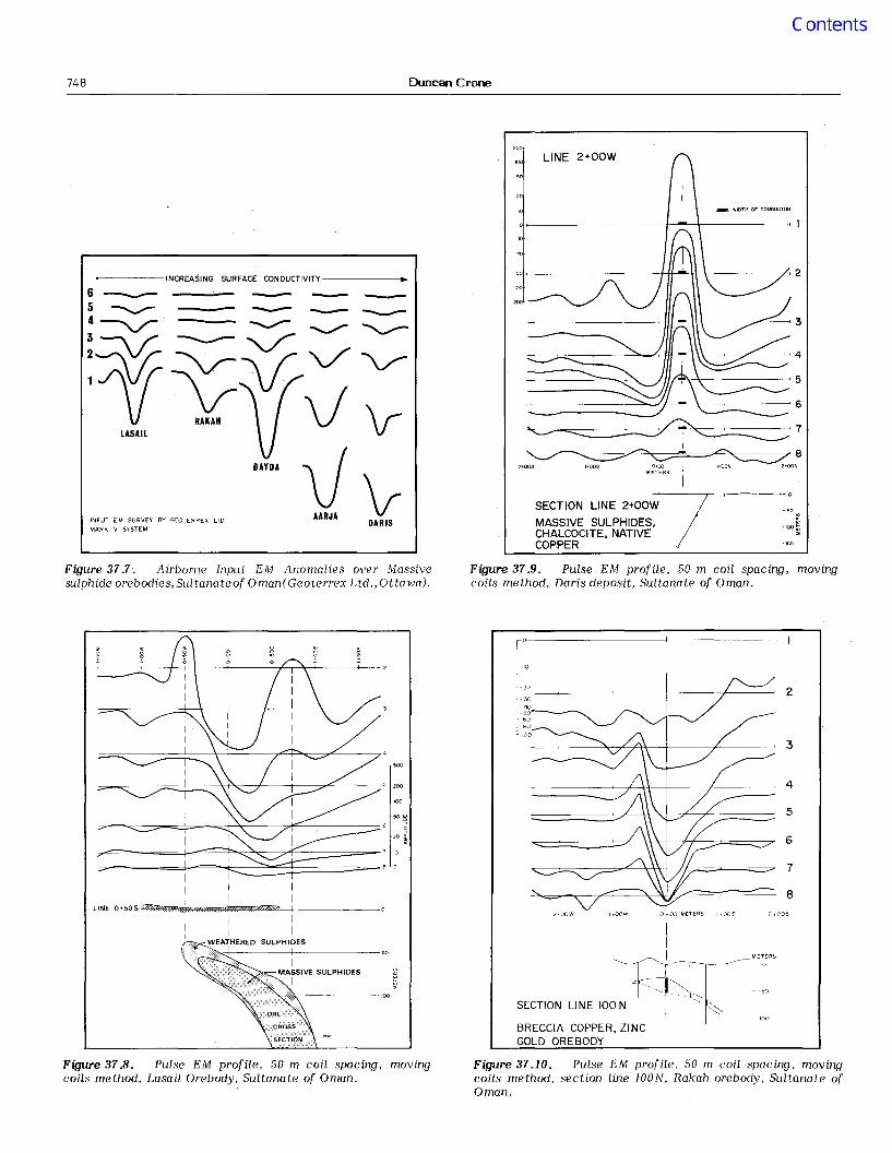
VY:Figure 37.7. Airborne Input EM Anomalies over Massivesulphide orebodies, Sultanate of Oman(Geoterrex Ltd.,Ottawa).
Figure 37,9. Pulse EM profile, 50 m coil spacing, movingcoils method, Daris deposit, Sultanate of Oman.
7
3
5
4
8
6
;:> .OOE0.00 METERS I.OOEI.Qaw2.DOW
III METERS
SECTION LINE loo~lll~-=BRECCIA COPPER, ZINCGOLD OREBODY
IO'~~~~~~~~~~+--~~~~~~-
+-10
120_~ ~__--+ --+-__~'" 2
I ~~·50'---_. 60
IMASSIVE SULPHIDES
I
'00
I 'I I
ILINE O+50SZil~~"'UP5"'ii~tJ_:C:'"""H\":t$!"'ot,"""",,",iZZ«¥iOi,",'B-'---+: ~~----o
! : IWEATHERED SULPHIDES
I I
Figure 37.8. Pulse EM profile, 50 m coil spacing, movingcoils method, Lasail Orebody, Sultanate of Oman.
Figure 37-10. Pulse EM profile, 50 m coil spacing, movingcoils method, section line JOaN, Rakah orebody, Sultanate ofOman.

Ground Pulse EM 749
This halting of the oxidation process leaves the central coreof the body as fresh sulphides of high conductivity. Anexcellent example of this phenomenon occurs in theWoodlawn lead-zinc-copper orebody in New South Wales,Australia (Fig. 37.4). Weathering of this 50 m-wide orebodystops at a depth of 12 m. The near-surface, fresh, massivesulphides of the Woodlawn orebody were at first consideredunusual for Australian climatic conditions. We have sinceencountered severed similar occurrences (without theWoodlawn grade) in Australia and other desert areas. Twoexamples are shown; the first example presented inFirjure 37.5 is a Pulse EM profile across the Maydan massivesulphide body in the mountains of Oman, which is 40 m wideand oxidized to 10 m. Figure 37.6 presents a Pulse EM profileacross a massive sulphide body in the Precambrian ofArizona, which is 15 m wide and is weathered to a depth ofapproximately 20 m. All three bodies occur in areas whereoxidation of narrow sulphide zones extends down to at least40 m. The occurrence of a strong, isolated zone of very highconductivity in a desert area can usually be attributed to awide, massive sulphide body. Such anomalies me uncommon,but are important exploration targets.
Field Examples from the Sultanate of Oman
Since 1973, Crone Geophysics Limited, has beeneonsulting for Prospection Limited of Toronto, who aremarlaging an exploration program in the SultanHte of Oman. Alarge area of Oman was flown by Geoterrex, with the InputMark V airborne EM system. Approximately 70 per cent ofthis area is covered by surficial conductors that produce abackground response down to the lowest Input [M channel. InFigure 37.7, the Input airborne EM response from fivemassive sulphide ore deposits is shown with backgroundconductivities, varying from low at the Lasail orebody, tohigh around the Daris deposit. All five orebodies are clearlydetected by the airborne EM survey with their signaturesuperimposed on the background surficial conductivityresponse. The ground Pulse EM profile over the Lasail copperorebody is shown in Figure 37.8. The background surficialresponse at Lasail is again almost zero. In this section theupper surface of the Lasail orebody is wider than the 50 mcoil spacing. Both eelges of the body are shown as positivetrending peaks with a large negative response being producedwhen both coils are located directly over the wide conductor.Figure 37.9 is a ground Pulse EM profile over the Darisdeflosit which is located on the outwash flats between thecoastal mountains and the Gulf of Oman. The surficialconductive overburden in that area produces a large negativeanomaly of minus 200 (normalized) divisions on the firstsample. With both the airborne and ground EM anomalies, thesurficial response in the Daris area in the early samples,exceeds in magnitude the peak response from the sulphides ofthe Lasail orebody. In both techniques, the Daris body isclearly detected with the sulphide anomaly beingsuperimposed on the surficial anomaly.
The discovery Pulse EM profile over the Rakah orebody,is shown in Figure 37.10. It is a typical response of a flat,dipping conductor with a conductivity thickness of 45 Mhos.The test borehole for such an anomaly was spotted as avertical hole at the maximum negative response; itintersected 30 m of 3% copper in a breccia sulphide zone. TheRakah body occurs at the foot of a mountain ridge and dipsunder the mountain. A Pulse EM profile along the steep sideslope of the mountain is shown in Figure 37.11. The ore zoneunder this profile is at a depth of 100 m and is barelydiscernible with the 50 m spacing Pulse EM profile. This typeof anomaly may weakly represent a conductor at this depth,but it lacks the definition required to accurately locate a testdrillhole.
Detailed Pulse EM Methods
When a marginal anomaly is detected by a ground PulseEM survey, a detailed survey is required to first establish ifthe anomaly is actual or noise, and secondly to provide theadditional information required to locate a test drillhole. Thedeeper the conducti ve target, the greater the need foraccurate position, depth, dip and width information.
The Pulse electromagnetic method has no geometricalrestrictions and therefore detailed measurements can beobtained with various transmit-receive coil configurations.The method also has the advantage of being able to measurethe secondary electromagnetic fields directly rather than as aresultant field reading in the presence of a primarytransmitted field. One of the most effective detailed methodsis to measure both horizontal and vertical field componentsand from these determine the direction of the secondaryfield. From this information measured at several stations, theinduced eddy current paths can be located. The induced eddycurrent paths within a conductor are shown by Lamontagneand West (1971) to be spaced apart. The distance ofseparHtion is dependent on the conductivity-thickness of thebody and the frequency of the induced field. Formeasurement points directly over the induced current path,the field is approximately circular and the eddy currentposition is located at the intersection point of lines drawn atright angles to the secondary field direction. Figure 37.12,ilJustrates the eight induced eddy current paths that wouldoccur in a weathered, massive sulphide body. The highfrequency, early-sample current paths wilJ flow along theoutside of the body and also within the poorly conductiveweathered sulphide and gossan areas. The late-sample eddycurrent paths will confine themselves to the highlyconductive, inner core of the massive body. As an example, astandard, moving horizontal coil Pulse EM profile over aknown massive orebody located in Western Australia ispresented in the upper part of Figure 37.13. The depth to thetop of the body is 100 m. The response of the standardmethod is within the noise level so that the observed anomalywould normally be considered questionable. A detailed surveywas therefore carried out which used a vertical transmitterloop oriented coplanar with the strike direction on a line120 m from the transmitter loop. The Pulse EM Sample 1 and2 field directions and orthogonal lines are shown in thebottom part of Figure 37.13. The eddy current path forSample 1 is located at a depth of 90 m. The slight scatter ofthe intersection points is caused by surficial conductivityeffects. The Sample 2 current position is accurately definedat 96 m depth. The vertical loop survey was used in this caseto selectively energize one edge of the sulphide body and todefine the location and depth of one side of the body.
THE DEEPEM TECHNIQUE
An alternative detailed method utilizes a 100 m square,single-turn transmit loop out on surface. This has theadvantage of a much stronger transmitted field providinggreater penetration, consequently the technique is calJed theDeepem method. The transmitter loop is laid out on one sideof the area to be detailed and the survey lines extend awayfrom the loop, starting 50 m from one wire out to a distanceof 350 m. Both horizontal and vertical components aremeasured and the induced current paths are determined asbefore.
An example of the use of the Deepem technique from atest survey over the Flying Doctor prospect, North BrokenHill area of Australia, is shown in Figure 37.14. In this casethe surficial conductivity which is caused by brackishgroundwater, has a conductivity of 4.2 ohm-metres to a depthof 7 m and a conductivity-thickness of 1.5 mhos. The massivesulphide body consists almost entirely of galena and

750 Duncan Crone
DEPTH 9QMEDDY CURRENT POsmON
o 49C(OE 50poE51<j>OE 5290£ I
IPULSE E.M • HORIZONTAL COILS 80M APART-10 I. I
.;r;-~ ~ 2
~ {Zl
_8
SAMPLE I
DEPTH 96MEDDY CURRENT POSITION
VERTICAL LOOP PE.M IDETAIL SURVEY t'"VERTICAL LOOP AT 1 (5060 E. 120 M SOUTH ·100
IIOrLI
Wto.E CONDUCTORr--+1OO100M DOWN F\I'--f'''---i!'N
=~==.:;;;;;;==;:;':;Z7~TZ;:;;:;/7;:;=:;j~;:;;:;?;:;?2:;?:;Z;:;7/:;Z;:;=;:;;:;:.======::'(3~
====::;;::;;;;;;;;;;;;=4:~~?=?2//Z22?Zv=~~;;·;;;;;;;;;;;;;;;;;====<4;~===~~==~-5
====:;;;;;~:=.;;;;;;---;t,iu;;;;:..:;;;;;;;;;;:======::::: 6
=-..........-=========::I~;;;;:;;;;:;;;;;;;.:::::========= 7
I
LINE 150NI
I 0J2
~~3~I
4 I
i5 I ~=:=<==""!:/'~6 • ~i A~::;y
7 p ......~ I~ "'!::/\=-~ 1'"""7' ,
8 ~/'C7~ ,£\=-.I ~=.c=----.3 .. 00W 2+00W (+oow 0'00 l+OOE 2+00E
I
- I METERS-0
SECTION LINE 140N_.",
BRECCIA COPPER, ZINC.::: -:::=:= '>
--100
GOLD OREBODY-~ 150
Figure 37.11. Pulse EM profile, 50 m coil spacing, movingcoils method, section line i40N, Rakah orebody, Sultanate ofOman.
Figure 37.13. PULSE EM surveys moving coils method andvertical loop detail method. Massive sulphide body, westernAustralia.
SURFACE
GOSSANNON CONDUCTIVE TOPOORLY CONDUCTIVE
FRESH MASSIVE SULPHIDESEXCELLENT CONDUCTIVITY
INDUCED EDDY CURRENT PATH FOR
SIXTH PULSE E. M. SAMPLE
~ .,::=
LINE 2525W
INDUCED EDDY CURRENTPATH POSITIONS FORFIRST SIX SAMPLES
TRANSMIT LOOP 100 MZ
FROM IO..OOW TO 13+3QW
/ j SURfiCIAL (J1" lSMHOS
~~~~:;j~T-'-: ~ j~'~ :~~~~::,~ --- --4 ~ ANDSPHALERIH
SULPHIDE en 9MHOS
GEOLOGICAL SECTION
Figure 37.12. induced eddy currents in a weatheredmassive sulphide body from the PULSE EM transmitter.
Figure 37.14. PULSE EM survey, detail vertical loop(Deepem) method, induced eddy current paths. Flying Doctorprospect, North Broken Hill, Australia.

Ground Pulse EM 751
Tx LOOP
300
7
••~•Tx lOOP 2
~7 I~O 200 METERS 3100 40y
FROM A SULPH I DEIN A CONDUCTIVEHALF SPACE
Tx lOOP 1
LINE 2525WVERTICAL FIELDCOMPONENT
TRANSMIT LOOP lOa Mol
FROM IO+QQW TO 13+30W
..--'
.'--.I --1 r----.....-' 17
, , ,
Figure 37.15. Pulse EM survey, detail(Deepem) method, vertical component,prospect, North Broken Hill, Australia.
vertical loopFlying Doctor
Figure 37.17. Pulse EM Deepem detail method, inducedcurrent paths in conductive half space containing a massivesulphide body and the application of two transmit loops.
SURFACE
CONDUCTIVE HALF SPACE
VECTOR METHOD OF
LOCATING THE INDUCED CURRENT
PATH - 3rd SAMPLE
300
~ 3rd SampleCurrent Path..........'i;--.........~ .......
@..........
-50
INDUCED CURRENT PATHSIN AN AREA OF HIGHSURFACE CONDUCTIVITY
50 100
METERS
MASSIVE SULPHIDECOPPER ZI NC OREBODY
DEEPEMLINE 3005
AARJA ORESODY - SULTANATE OF OMAN
" -II I
\ ' /....._,~/
i/'-"
t...-J., }/"5'~
I I II I I
oS, I 6/I}. I
i tilI '7vt I\ I
''''-''
- 100
"''"w>-w -150
"- 200
300
VECTOR METHOD OF
LOCATING THE INDUCED CURRENT
PATH IN A SULPHIDE
CONDUCTOR - 3rd SAMPLE
Figure 37.16. PULSE EM Deepem detail method, Inducedcurrent paths in a conductive half space and massive sulphidebody.
Figure 37.18. Pulse EM Deepem detail method over AarjaOrebody, Sultanate of Oman.

752
500'
1000'300m
-100fJ VOLTS
-10 0
Duncan Crone
CONDUCTOR
DIP -300
SIZE 1500')Ii 1000'450m x 300m
DEPTH TO INTERSECTIONIS 1250' (380m)
BOREHOLE E.M.
Borehole inside the conductor120 meters (400 feet) from theedge.
500'
1000'
2000'
~ VOLTS
CONDUCTOR
DIP -30 0
SIZE 1500')( 1000'450 )Ii 300 meters
DEPTH TO EDGE15 1250' (380m)
BOREHOLE E.M.
Borehole at the edge of theconductor
Figure 37.19, Pulse EMresult from a conductivesheet 400 ft from its edge.
borehole method. model studysheet. borehole intersecting the
Figure 37.21.result from asheet.
Borehole pulse EM method, model studyconductive sheet, borehole just outside edge of
500'
I~O'
J2000'
600m
-100 -10
CONDUCTOR
DIP - 30°
SIZE 1500')Ii 1000'450 x 300 meters
DEPTH TO INTERSECTIONIS 1250' (380m)
BOREHOLE E.M.
Borehole inside the conductor15 meters (50 feet) from theedge
CONDUCTOR
DIP -30 0
SIZE 1500')( 1000'. 450 )Ii 300 meters
DEPTH TO MIDDLE POINT[S 1250' (380m)
500' -
1500'
2000'
BOREHOLE E.M.
Conductor edge 150 meters(500 feet) from the borehole
+100
Figure 371.20. Borehole pulse EM method. model studyresult from a conductive sheet. borehole intersecting thesheet 50 ft from its edge.
Figure 37.22.result from aedge of sheet.
Borehole pulse EM method, model studyconductive sheet, borehole 500 ft and outside

Ground Pulse EM 753
SAMPLE AMPLITUDEi280 640 .20 160 80 40 20
-----t----
SECTION 2525W, BOREHOLE 3039
CRONE BOREHOLE P.E.M. SURVEY
120I
I r
/ I/ /
/ /' I
/ / l111/
11 -
100I
"'060 "'-9 80I I
METERS
40,
ZONE
LEAD - ZINCSULPHIDES
20I
GAIN CONSTANT AT 500
WEATHERED
20 -
80 -
90 -
100 -
FLYING DOCTOR PROSPECT, NORTH BROKEN HILL AREA,AUSTRALIA.
~
f- 60-
,
BOREHOLE CUTS WEATHERED SULPHIDESIMMEDIATELY ABOVE FRESH SULPHIDES
Figure 37.23. Borehole pulse EM survey, borehole just outside the upper edge of Flying Doctor lead-zincbody, North Broken Hill, Australia.
BOREHOLE CUTS THROUGH CENTRE OFCONDUCTIVE GALENA - SPHALERITE BODY
120
140
LEAD ZINCSULPHIDES
12010080
ZONE
METERS
60
WEATHERED
40
90
20
40
80
100
SECTION 2525W, BOREHOLE 3040
FLYING DOCTOR PROSPECT, NORTH BROKEN HILL AREA,AUSTRALIA.
CRONE BOREHOLE P.E.M. SURVEY
I~~ ~o~p --@ ----+---------_-,.-----
1
(
90
110
5 4 3 2
10 ~ \ \ 1~\ \ \ Ii \ 1\ \ \
20 •• \ \ i\ \ \ \i \ i
30 _\ \ \
\ \ \\ \ \ \
\ \ \40 ~I \ \ \
I; \ \ \\ \ \
;;1 \ \ \50;;;\ \ \ \
:; \ \ \ \
~ 1\ \ \ \W~ 60 \ \ \ \
\ \ \
= 1 1\ \ \ \\ \ \
S: 70 ~- \ , \ \ \ \
~ 80 \'", "'<~'" '"'\\", """ .,<~"~~\\ "~.,,,.,
) \ "\~--- \ i1\ • l
\ /' /<' j}\ /-Vp
I /" /~~/ " /'~1l;8 654321
LEAD ZINC /
SULPHIDES -"~.2
Figure 37.24. Borehole pulse EM survey, borehole intersecting the middle portion of Flying Doctor lead-zincbody, North Broken Hill, Austraila.

754 Duncan Crone
FLYING DOCTOR PROSPECT. NORTH BROKEN HILL AREA.AUSTRALIA.
SECTION 2525W. BOREHOLE 3071
i 60--
lONE
/ '/ II' I, /
I I'
/ /It'/ I 11..... _
LEAD ZINCSULPHIDES
SAMPLE AMPLITUDE
20 40 80 160 320,-~I---+----+-- I I I
line. This resultant current path for the early or highfrequency samples, will be dominated by the surficialconductivity response. The later sample or low frequencyresultant response, will be influenced to a greater degree bythe more conductive sulphide body. The net effect is for theresultant current path to form a line that lies between thesurficial and sulphide current paths. If transmitter loops areemployed on either side of the target area, then theapproximate position of the sulphide zone can be determinedas the area enclosed by the two resultant current paths, asshown in the lower portion of Figure 37.17.
The two"transmitter Deepem procedure was first testedin a profile over the Aarja massive sulphide body in theSultanate of Oman. The body approximates a cylinder some50 to 100 m in diameter of massive sulphides that has ashallow plunge of 20 0 from the horizontal. The test sectionhas a depth to the top of the sulphide zone of 150 m. Thesurficial conductivity in this area is 9 ohm m to a depth ofapproximately 30 or 40 m. The resultant induced currentpaths are shown in Figure 37.18; the eddy current paths fromthe eastern transmit loop as dashed circles, the paths fromthe western loop as solid circles with the orebody occurringbetween.
Further tests with the Deepem method in Australia,indicate that the induced current path method does notoutline deep (100 m plus) massive sulphide conductors, whenthe surficial conductivity-thickness product is of the order of10 Mhos. In this casc the anomalous information is availablein the measured readings but thc eddy currenL path methodlacks the sensitivity to unlock the sulphide response from thestrong surficial response. Computer processing of theobserved data to strip off the surficial conductivitybackground effect is now being investigated.
Figure 37'..25. Borehole pulse EM survey 20 metres awayfrom the lower edge of Flying Doctor lead-zinc body, NorthBroken Hill, Australia.
sphalerite with a calculated conductivity-thickness from thePulse survey of 9 Mhos. The body is weathered to a depth of40 m. The first Pulse EM sample is dominated by the surficialconductivity and does not form an eddy current path position.The second, third and fourth samples produce eddy currentpath positions along the contact of the sulphide lens thatfaces the transmitter loop. Because the sulphide lens has Cllow conductivity, the response of the fifth and sixth samplesare we3k and the eddy current paths are not accuratelydefined. In order to show the amplitudes of the responsesmeasured, the vertical component is usually plotted as shownin Figure 37.15. The conductor is located below the crossover position.
Limitations of the Deepem Detail Method inAreas of High Surficial Conductivity
The presence of a conductive half spsce below thetransmitter loop results in eddy currents that flow inconcentric rings around and outside the loop. The first sampleeddy current flows close to the loop, with the later samplesspaced farther out as shown in the uppcr portion ofFigure 37.16. The interval between the eddy current pathsdecreases as the conductivity-thickness of the half spaceincreases. The lower portion of Figure 37.16, shows thecurrent paths induced in a massive sulphide body without thepresence of a surficial conducti ve zone. When the sulphidebody occurs in a conductive half space, then both surficialand sulphide eddy currents are present as shown in the upperportion of Figure 37.17. In this csse, a resultant current pathwill be detected by the receiver that is shown as a dashed
BOREHOLE PULSE EM METHOD
Crone Geophysics developed in 1976, a Borehole PulseEM system for the Geological Survey of Canada with depthcapabilities in excess of 1000 m. The method uses a largesingle-turn transmitter loop laid out on the ground and areceivcr probe sent down the borehole. The advantages of theBorehole Pulse EM system are; (1) Since the method is free ofgeometrical effects, anomalies are not caused by variances inthe stmightness of the borehole. (2) The measurement of thesecondary fields directly provides accurate interpretativeinformCltion. (3) The wide frequency spectrum enables themethod to separate effects from weakly mineralized sulphidezones intersected within the hole from large massive bodieslocated outside the hole.
A model study was carried out (Woods, 1975) as an aidto the interpretatiun of Borehole Pulse EM data. This studyillustrCltes that Borehole Pulse EM is effective in detectingmassive sulphide bodies and also provides an idea of the size,shape and position of the sulphide body. Figures 37.19 to37.22 illustrate the change in the response pattern obtainedwhen the borehole is moved from an intersecLion from 120 minside a conductive sheet to 150 m outside. The response unitin this model study are microvolts of signal received at Lhedownhole probe and are not normalized.
Field results me shown from a survey of three holes in asection from the Flying Doctor prospect. This is the samesection that was detailed with the Deepem method. Thethree holes were Clll surveyed from a 100 m square, singleturn, transmitter loop located immediately west of the collarof borehole 3071. In Figure 37.23, the Borehole Pulse [Mresults from borehole 3039 are shown. This hole intersects theupper weathered portion of the sulphide zone. The surveycurves match those of Figure 37.21 of the model study. Thiswould indicate that the weathered sulphides intersected inthe hole are nonconductive, but the hole is just outside the

Ground Pulse EM 755
conductive sulphide zone. In Figure 37.24, the downholeresults from hole 3040 are shown to produce the typicalpositive response obtained when a borehole intersects aconductive sulphide zone, with the intersection point locatedtowards the central part of the body (model study Fig. 37.19).Casing in this hole blocked out readings between 30 and 65 m.The survey of borehole 3071 (Fig. 37.25) shows that the minorsulphide zones intersected at 117 and 136 m are bothnonconductive but that two conductive bodies are locatedsome 10 to 20 m from the hole. The upward displacement ofthe negative response peaks from the intersection of minorsulphides, indicates that the massive sulphides occur up dipfrom the intersection.
CONCLUSIONS
The ground Pulse electromagnetic method is aneffective exploration tool in the search for massive sulphidebodies in desert areas. The method is very flexible as far ascoil configurations and field component measurements areconcerned. A large number of field measurements can beobtained at each observation point. Advancements in thecomputer processing of such a large data base, should lead tofurther increased depths of penetration and accuracy of thePulse EM method. Developments in the Borehole Pulse EMtechnique have expanded the radius of detection ofmineralization from a drillhole from a few centimetres ofcore up to 150 m. Thus this capability of the Borehole PulseEM technique will permit exploration at depth in the vicinityof known ore deposits.
REFERENCES
Crone, J.D.1975: Pulse Electromagnetic - PEM ground method
and equipment as applied in mineralexploration; AIME Annual Meeting, New York,1975, Preprint 75-L-93, 8 p.
Dolan, W.M.1967: Geophysical detection of deeply buried sulphide
bodies in weathered regions; in Mining andGroundwater Geophysics, Geol. Surv. Can., Econ.Geol. Rept. 26, p. 336-344.
Lamontagne, Y.I. and West, G.F.1971: EM response of a rectangular thin plate; in
Research in Applied Geophysics, v. 2, GeophysicsLab., Univ. of Toronto.
Wait, J.R.1956: Method of geophysical exploration; U.S. Patent
Office 2,735,980.
Woods, D.V.1975: A model study of the Crone Borehole Pulse
Electromagnetic (PEM) system; unpubl. M.A.thesis, Dept. of GeologicFll Sciences, Queen'sUniv., Kingston, Ontario.