Exploiting Telerobotics for Sensorimotor Rehabilitation: A ...
39
Exploiting Telerobotics for Sensorimotor Rehabilitation: A Locomotor Embodiment Min Hyong Koh Northeastern University Sheng-Che Yen Northeastern University Lester Y. Leung Tufts Medical Center Sarah Gans Tufts Medical Center Keri Sullivan Tufts Medical Center Yasaman Adibnia Tufts Medical Center Misha Pavel Northeastern University Christopher J. Hasson ( [email protected] ) Northeastern University Research Article Keywords: teleoperation, rehabilitation, stroke, locomotion, gait, robotics, sensorimotor control, motor learning Posted Date: January 15th, 2021 DOI: https://doi.org/10.21203/rs.3.rs-148435/v1 License: This work is licensed under a Creative Commons Attribution 4.0 International License. Read Full License
Transcript of Exploiting Telerobotics for Sensorimotor Rehabilitation: A ...

Exploiting Telerobotics for SensorimotorRehabilitation: A Locomotor EmbodimentMin Hyong Koh
Northeastern UniversitySheng-Che Yen
Northeastern UniversityLester Y. Leung
Tufts Medical CenterSarah Gans
Tufts Medical CenterKeri Sullivan
Tufts Medical CenterYasaman Adibnia
Tufts Medical CenterMisha Pavel
Northeastern UniversityChristopher J. Hasson ( [email protected] )
Northeastern University
Research Article
Keywords: teleoperation, rehabilitation, stroke, locomotion, gait, robotics, sensorimotor control, motorlearning
Posted Date: January 15th, 2021
DOI: https://doi.org/10.21203/rs.3.rs-148435/v1
License: This work is licensed under a Creative Commons Attribution 4.0 International License. Read Full License

1
Exploiting Telerobotics for Sensorimotor Rehabilitation: A Locomotor Embodiment
Min Hyong Koh1, Sheng‐Che Yen1, Lester Y. Leung2, Sarah Gans2, Keri Sullivan2, Yasaman Adibnia2, Misha Pavel3, and Christopher J. Hasson1,4
1Department of Physical Therapy, Movement and Rehabilitation Sciences; Northeastern University 2Division of Stroke and Cerebrovascular Diseases, Department of Neurology; Tufts Medical Center
3Khoury College of Computer Sciences; Northeastern University 4Departments of Bioengineering and Biology; Northeastern University
†Address for Correspondence: Christopher J. Hasson Department of Physical Therapy, Movement and Rehabilitation Sciences Northeastern University 360 Huntington Avenue 301 Robinson Hall Boston, MA 02115‐5005 E‐Mail: [email protected]

2
ABSTRACT Background: Manual treadmill training is used for rehabilitating locomotor impairments but can be physically demanding for trainers. This has been addressed by enlisting robots, but in doing so, the ability of trainers to use their experience and judgment to modulate locomotor assistance on the fly has been lost. This paper explores the feasibility of a telerobotics approach that allows patients to receive physical assistance from robotically augmented trainers. Methods: In the approach, a trainer holds onto a small robotic manipulandum that shadows the motion of a large robotic arm, which is magnetically attached to the leg of a locomoting patient. When the trainer deflects the manipulandum, the robotic arm applies a proportional force to the patient. After an initial evaluation of the telerobotic system’s ability to follow the leg during unassisted locomotion with unimpaired participants, a small feasibility study was performed with six patients with prior strokes. Over six days, the patients interacted with two robotically augmented trainers (separately), who assisted in altering a targeted gait feature: an increase in the affected leg’s swing length. Results: During unassisted walking, unwanted robot interaction forces averaged 3−4 N (swing−stance) for unimpaired individuals and 2−3 N for the patients who survived strokes. Transients averaging about 10 N were sometimes present at heel‐strike/toe‐off. For five of six patients, these forces increased with treadmill speed during stance (R2 = .99; p < .001) and increased with patient height (R2 = .71; p = .073) during swing. During assisted walking, the trainers applied 3.0 ± 2.8 N (mean ± standard deviation across patients) and 14.1 ± 3.4 N of force anteriorly and upwards, respectively. The patients exhibited a 20 ± 21% increase in unassisted swing length between Days 1−6 (p = .058). Conclusions: The results support the feasibility of locomotor assistance with a telerobotics approach. Simultaneous measurement of trainer manipulative actions, patient motor responses, and the forces associated with these interactions may prove useful for testing sensorimotor rehabilitation hypotheses. Further research with clinicians as operators and randomized controlled trials with more comprehensive outcome measures are needed before conclusions regarding efficacy can be reached. Key Words: teleoperation; rehabilitation; stroke; locomotion; gait; robotics; sensorimotor control; motor learning

3
BACKGROUND
Background and Rationale Locomotor impairments can arise from injuries or disease processes that disrupt sensorimotor operations, such as spinal cord injuries and stroke. Locomotor training may be incorporated into a rehabilitation program. One approach uses a treadmill because it allows tight control over walking speed and terrain and facilitates the use of a body‐weight support system [1, 2]. During treadmill training, human trainers can provide physical assistance to facilitate limb movement and support trunk stabilization [3]. High‐volumes of task‐orientated practice can promote neuroplasticity [4]. Although treadmill training has shown positive results for patient populations, including individuals who have had strokes [5, 6] or incomplete spinal cord injuries [7, 8], the overall efficacy is not unambiguously superior to other methods such as over‐ground training or general exercise regimens [2, 9‐13]. Explaining the inability of manual treadmill training to consistently meet expectations presents a grand challenge due to high investigational variability (e.g., eligibility criteria and intervention parameters [14]). When providing physical assistance to elicit targeted modifications of a patient’s locomotor pattern, human trainers must contend with relatively complex patient dynamics. This includes the gravitational and inertial forces associated with the large wobbling mass [15] of a patient’s upper body, which is alternately supported by multi‐link segmental chains (the legs) during locomotion. Further, the joints spanning these segments are actuated by a redundant set of viscoelastic muscles [16] controlled by a possibly impaired nervous system. Trainers also face significant sensorimotor constraints. They often need to produce large forces while kneeling or sitting with a limited view of a patient’s body and need to keep up with rapidly swinging patient limbs to prevent unintended interaction forces, which demands predictive control processes due to sensorimotor delays [17]. The combination of complex interactive dynamics, high forces, and rapid movements creates a challenging task that may limit trainer effectiveness. One way to address the physical limitations of human trainers is to enlist the help of robots [18‐20]. However, in doing so, human trainers have been relegated to a supervisory role. At the same time, robotic gait training outcomes have not proven dependably better than conventional rehabilitation approaches for spinal cord injury [21, 22] or stroke [23‐27]. Giving trainers more online control of the robotic system (trainer‐in‐the‐loop) could improve rehabilitation outcomes. The rationale is that trainers can use their experience and judgment to customize locomotor assistance on the fly, and their relatively high degree of motor execution variability could be a feature instead of a bug. Self‐generated (intrinsic) variability can promote the exploration of novel motor actions that drive learning [28, 29]. Could this also hold for variability injected from an external source, i.e., from a trainer to a patient? If so, these advantages could be masked by trainer fatigue or other sensorimotor encumbrances. These points lead to the principal question: Would treadmill training outcomes improve if trainers remained in control, were relieved of high physical demands, and received augmented feedback about their patient interactions? Telerobotics, or robotics with a human operator in the control loop [30], may provide a viable approach to answering this question. Although telerobotics has been broadly researched, for example, in areas related to telesurgery (see [30] for a review), rehabilitation applications with continuous physical interaction between clinicians and patients are more limited. Most existing telehealth approaches only permit visual and auditory communication [31‐34]. One study investigated the feasibility of remote haptic communication using an exoskeleton to record the movements of patients who have had strokes; these movements were subsequently played back using an exoskeleton worn by therapists [35]. By feeling the patients' movements through the exoskeleton, the therapists were able to identify abnormal movement patterns. Although the results are promising, synchronous online physical interaction was not investigated, and the therapists could not command the robotic system to apply forces to patients. There is a significant need for telerobotics approaches that allow real‐time bi‐directional physical interaction between trainers and patients, which, in addition to benefits associated with human‐human interaction (see previous paragraph) may be useful with heightened disease transmission risks.

4
Structure of Report This report is divided into three sections: 1. The first section introduces a telerobotics approach that allows online physical interaction between a trainer and patient. Here, the approach is embodied in the context of locomotor recovery. A trainer holds onto a small robotic manipulandum that provides real‐time haptic feedback about a patient’s locomotor actions, so the trainer feels like they are holding onto a miniature version of the patient (Figure 1A). A visual display shows information related to patient errors and training progress. The trainer can assist by applying light forces to the manipulandum, which are amplified and transferred to the patient’s affected leg using a magnetically attached robotic arm (i.e., teleoperation). The use of a robotic arm for locomotor training deviates from conventional approaches that use exoskeletons [36‐39], cables [40, 41], or footplates [42, 43] to apply force to patients. In contrast to an exoskeleton, the robotic arm requires only a small piece of metal, embedded in a brace or garment, to engage with a patient. With an array of suitable attachments, a robotic arm can interface with most body parts. 2. The second section of this paper describes the results of preliminary tests on unimpaired participants. These tests focused on the system’s transparency, which refers to the relative ease at which an individual can move (or back‐drive) the robotic arm during unassisted locomotion, which constitutes a zero‐impedance, zero‐force, or patient‐in‐charge mode of robot operation [44]. This section also validates a procedure that reduces errors in swing‐length estimation due to small day‐to‐day variations in the location of the robot attachment on the patient’s leg. 3. The third section describes a small feasibility study with six individuals who have experienced strokes. The purpose of the feasibility study was to gather information to design more extensive clinical trials that answer the main question posed earlier: whether the outcomes of treadmill training would improve if human trainers remained in control, were relieved of high physical demands, and received augmented feedback about their patient interactions. Several preliminary questions were formulated: Regarding Transparency: In a small clinical sample constituting individuals who have had prior strokes, how transparent is the telerobotic system during locomotion? How is the system’s transparency affected by treadmill speed and patient anthropometry? (n.b., the magnitude of unwanted interaction forces quantified transparency.) Regarding the Trainers: What forces do trainers command with the small manipulandum when providing locomotor assistance to patients? How do trainer manipulandum forces change from day‐to‐day; how do they differ between trainers? To what degree do the forces applied to patients by the robotic arm reflect those commanded by trainers? Regarding the Patients: Can the patients complete a six‐day telerobotics locomotor training protocol successfully? Is the telerobotics system able to elicit a targeted change in patient gait, operationally defined as a 25% increase in the affected leg's swing length? Do these changes persist over multiple training sessions? The clinical population was chosen because hemiplegia is typically associated with an asymmetric locomotor pattern, such that one leg has a shortened step length and may have difficulty with ground clearance [45]. In this case, only a single robotic arm is needed to assist the affected leg. Future work can extend the approach to other populations, for example, by adding a second robotic device or working collaboratively with human trainers. It should be emphasized that rather than providing definitive answers, this study was designed to provide preliminary data related to each of the questions posed, to be evaluated further in future studies.
METHODS
Section 1. Description of the Telerobotics Approach Patient Interface Robot‐Patient Coupling: Locomotor assistance was provided with a commercially available robotic arm (WAM; Whole‐Arm Manipulator, Barrett Technology, Newton MA), which was magnetically attached to the lower leg near its center‐of‐mass (Figure 1A). The robot‐patient coupling consisted of two parts: a semi‐rigid ankle brace with a small steel cup
5
worn by patients and a joystick and magnet mounted on the end of the robot (Figure 1B). This coupling improves upon an earlier design [46] by adding the joystick (M31L081P, APEM Inc.), which has potentiometers to measure the coupling angle along two axes; the third axis (axial rotation) was not measured. The joystick added three passive degrees of freedom (DOFs) to the robot arm, bringing the total DOFs to seven (four active and three passive; the four active DOFs were measured with incremental encoders with a resolution of 0.005°). The additional passive DOFs provided sufficient robot mobility to limit undesired interaction torques between the robot and patients. The robot attachment state was monitored with a pair of DuPont connectors that pulled apart, opening a circuit if the robot detached from the leg. The joystick potentiometer and attachment state circuit voltages were digitized by a microcontroller (Pro Micro 5V/16 MHz, SparkFun) and sent via USB to the robot control computer. A 3D‐printed plastic housing held the joystick, which was bolted to a force sensor on the end of the robotic arm. The force sensor used bonded silicon strain gauges with a resolution (i.e., smallest distinguishable difference) of 50 mN perpendicular to the long axis of the end effector and 80 mN axially. Mechanical Fuse: A neodymium ring magnet (RX038DCB, K&J Magnetics Inc.) acted as a mechanical fuse to separate the robot from the patient in the event of a mechanical overload. The magnet was screwed into the joystick on the end of the robot (Figure 1B). The magnet had an axial pulling force of 176 N. This magnet strength was chosen so that it would be strong enough to securely maintain the robot‐human connection but would release if an unusual force or torque was applied (mechanical overload). This was determined empirically by the investigators, who separately walked on a treadmill with the robotic arm attached to their legs. Various magnet strengths were tested by walking at different speeds with different symmetrical and asymmetrical gaits; different stumbling actions were also reproduced (a safety harness was worn). The magnet strength was chosen so that the robotic arm stayed attached during all walking variations, including minor stumbles; however, when a stumble caused an exceptionally severe alteration in walking kinematics, there was a complete loss of balance, or if the tester stopped walking (and thus moved rearward), the robot detached (these were considered mechanical overloads).
Robotic Arm Control: The robotic arm used for the patient interface achieved high intrinsic back‐drivability with a low‐friction cable transmission system with zero‐backlash, i.e., there was a tight linkage between the commanded motor torques and the resulting torques on the joints of the robot arm. A dedicated real‐time computer (Ubuntu 14.04.5; Linux Kernel 3.14.17; Xenomai 2.6.4) closed a 1000 Hz torque control loop using a CAN (Controller Area Network) bus for rapid real‐time communication between the computer and the robotic arm. The control loop incorporated a series of actions: sending position information to the computer, calculating desired torques, and sending appropriate motor torque commands to the robotic arm. The torque controller included gravity compensation to support the robot arm’s weight. For this compensation, a manufacturer‐supplied routine estimated the first moment of mass vectors for each robot linkage (assuming a static case; for more details, see manuals and documentation provided by the manufacturer, Barrett Technology). Henceforth, the manufacturer‐supplied torque controller is referred to as the native controller. Typical rehabilitative applications of robot arms include goal‐directed upper‐extremity tasks [47‐49]. In this study, the robotic arm was attached to the lower‐leg during locomotor training, which places a unique set of demands on the robot controller. The human gait cycle typically includes a brisk low‐impedance swing phase, followed by a large impact at heel‐strike, and a slower high‐impedance stance phase. High back‐drivability of the robot arm during the swing phase was of particular concern. Pilot testing showed that although the native controller permitted a good deal of back‐drivability, the robot arm's presence was noticeable during the swing phase of gait (the native controller does not compensate for the robot’s inertia and other unwanted forces). Therefore, this study sought to improve the transparency of the native controller, i.e., increase the ease at which the patient’s leg can back‐drive the robot and reduce unwanted interaction forces (forces other than those applied by a human trainer operating the system). One approach to improving transparency is to incorporate information about end‐effector interaction forces into the control scheme, which can be used to compensate for unmodeled robot arm dynamics, such as inertia [36, 50‐52]. The force sensor mounted on the end of the robotic arm measured the three‐dimensional force applied to the patient 𝑭𝑹 (boldface denotes a vector quantity). A gain‐scheduled proportional‐integral force controller (Figure 2) was used to improve transparency and transmit assistive or resistive forces commanded by a human trainer 𝑭𝑻 . For unassisted/unimpeded patient locomotion 𝑭𝑻 𝟎; more details on determining 𝑭𝑻 are presented in the Trainer

6
Interface section that follows. To render 𝑭𝑻 on the patient, the controller regulated the robot arm motor torques 𝝉𝑪 (three shoulder/one elbow) according to 𝝉𝑪 𝑡 J 𝒒𝒋𝒐𝒊𝒏𝒕 𝑡 𝑭𝑪 𝑡 (1) where J 𝒒𝒋𝒐𝒊𝒏𝒕 is the Jacobian transpose matrix (transforms endpoint forces to joint torques), 𝒒𝒋𝒐𝒊𝒏𝒕 are the robot arm joint angles, and 𝑭𝑪 is the controller force defined as 𝑭 𝑡 𝑘 𝑭𝑬 𝑡 𝑘 𝑭𝑬 𝑡 𝑑𝑡, (2) where 𝑘 and 𝑘 are proportional and integral gains indexed to locomotor events, 𝑭𝑬 is the force error (𝑭𝑬 𝑭𝑻𝑭𝑹), 𝑡 is a timestamp marking the previous heel‐strike, and 𝑡 is a timestamp identifying the most recent force and position measurements (updated every millisecond). The timestamp 𝑡 was identified online as the maximum anterior displacement of the robot arm end‐effector on the previous step; this event typically occurred just before the heel contacted the treadmill. The integrated error was reset to zero after each step at 𝑡 . Under this control scheme, the higher the gains (𝑘 and 𝑘 , the more aggressively the robot arm tried to drive 𝑭𝑬 to zero. A gain‐scheduled force controller was used because the mechanical impedance (a dynamic extension of stiffness [53]) of the human leg varies significantly across the different phases of gait [54]. When the robotic arm is connected to a low‐impedance environment, such as the leg during the swing phase of gait, a high force controller gain is desirable as it makes the robot controller aggressively track 𝑭𝑻. However, when the robot is connected to a high‐impedance environment, e.g., the leg during the stance phase, contact instabilities can result, particularly with high force‐feedback gains [53]. Since one would typically not try to move an individual’s leg out from beneath them when it supports a portion of their body weight during stance, the controller gain can be lowered during this time. Specifically, just before heel‐strike (𝑡 ) the controller gains were lowered to 𝑘 1.0 and 𝑘 0.005. The gains were held constant during the stance phase until just before heel‐off; the latter was identified online as the maximum posterior displacement of the robot arm end‐effector. Subsequently, the gains were raised to 𝑘 6.0 and 𝑘 0.4 during leg swing until the next 𝑡 . The gains were determined using a manual tuning process with unimpaired participants walking on a treadmill. The gains were initially set low and gradually increased until there was a noticeable oscillation of the robotic arm, which indicated that the controller’s stability was becoming compromised. Gain values just below the level of noticeable robot oscillation were chosen separately for the stance and swing phases of gait. Trainer Interface Integral to the telerobotics approach is a trainer interface that consisted of a small robotic manipulandum (Geomagic Touch, 3D Systems, Rock Hill, SC) and visual display (Figure 1C). The manipulandum followed a scaled‐down version of the robotic arm end‐effector position, shadowing the movement of a patient’s leg during treadmill locomotion (see flowchart in Figure 2). This tracking was achieved using a virtual spring, which commanded the manipulandum motors to produce torques to render a manipulandum end‐effector force 𝑭𝑴 according to 𝑭𝑴 𝑡 𝑘 ∆𝒅 𝑡 (3) where ∆𝒅 is the difference between the measured manipulandum position and the scaled robot arm end‐effector position 𝑷𝑳𝑬𝑮, and 𝑘 is a spring constant (0.2 N/mm). 𝑷𝑳𝑬𝑮 was downscaled by a factor of 0.125. The constant 𝑘 was determined by asking a human trainer to hold onto the manipulandum as another healthy individual walked on a treadmill with the robotic arm attached to their leg. The human trainer was instructed to just follow along and not interfere as 𝑘 was varied. The 𝑘 used was the highest that permitted good tracking performance without noticeable oscillations. The manipulandum control scheme was modified so that, instead of just following along, the human trainer could dynamically take charge and deliver a time‐varying manipulative force to a patient. The goal was to use an intuitive approach. For example, if a trainer wants to assist with foot clearance, the trainer should be able to lift and deflect the manipulandum upwards at the appropriate time in the gait cycle. Further, the more the trainer pushes on the manipulandum, the more the manipulandum should deflect, and the force transmitted to the patient should increase (within limits). This deflection is captured by ∆𝒅. The force transmission scheme (Figure 3) was implemented as

7
𝑭𝑻 𝑡 ⎩⎪⎨⎪⎧ 𝐹 ∆𝒅
|∆𝒅 |if ∆𝑑 |∆d t |
|∆𝒅 | ∆∆ ∆ 𝐹 ∆𝒅|∆𝒅 |
if ∆𝑑 |∆𝒅 𝑡 | ∆𝑑
0 otherwise
(4)
where 𝑭𝑻 represents the trainer’s commanded force (which the robot arm tries to produce; see Equation 2 and accompanying text), the threshold ∆𝑑 (4 mm) defined the radius of a deadband about the downscaled patient leg position, and ∆𝑑 (8 mm) scaled the overall amount of force amplification by establishing the maximum desired assistance force (𝐹 30N). If |∆𝒅| was below ∆𝑑 then no force was commanded. If the trainer force exceeded the deadband, then a force was commanded that scaled with ∆𝒅. The deadband was necessary so that sensorimotor noise in the trainer did not cause unintended force commands. The effective amplification factor increased with the trainer input force, with an amplification factor of 18.75 at ∆𝑑 . 𝐹 was based on the maximum payload of the robotic arm (about 40N), reduced by a safety factor of about 35%. Note that the direction of 𝑭𝑻 was always the same as ∆𝒅 and force transmission occurred in two‐dimensions aligned with the sagittal plane of the patient. The trainer forces were software limited to be in the anterior and upwards directions so that the trainer could not command forces that resisted patient motion. This limiter could be turned off in software and was in one case for Patient 3 (see Methods Section 3). No force was transmitted during a time‐window starting at heel‐strike and ending 200 ms later. Trainer Visual Display: During locomotor training, trainers received visual feedback on a computer monitor. The visual display showed the location of the robot arm endpoint (attached to a patient’s leg) and was updated at 50 Hz (Figure 1C). A short “tail” was provided, showing the last second of motion. A target swing length was shown as two vertical lines. Although the orientation of the patient’s leg could be estimated and shown to the trainer on the visual display, a recent study by Hasson and Jalili [55] showed that seeing the patient’s leg does not provide a significant benefit in terms of learning the patient dynamics, and therefore only the robot attachment point was shown. Section 2. Preliminary Work Robot Arm Controller Transparency Given that transparency (i.e., the ability of the robotic system to move with a patient during unassisted locomotion) is a basic requirement of most robotic rehabilitation systems, an initial transparency evaluation was performed with two unimpaired male participants (U1: investigator MK; U2: investigator CJH; see Table 1 for descriptive characteristics). The participants walked on a treadmill at 0.45 m/s with and without the robot attached to the leg. At this very early stage of evaluation, the investigators participated so that any necessary refinements could be made prior to recruiting naive individuals or patients (all procedures were approved by the Northeastern University and Tufts Medical Center Institutional Review Boards). In each condition, the participants walked for four minutes while leg kinematics were collected using a four‐camera optical motion‐capture system (120 fps, Flex 13, OptiTrack, NaturalPoint, Inc., Corvallis, OR). Passive reflective markers (1 cm spheres) were placed on the right leg at two locations: one representing the hip joint center (greater trochanter of the femur) and one representing the robot attachment site (the proximal aspect of the rim of the metal cup accepting the magnetic attachment from the large robotic arm). Markers were tracked in 3D (Motive version 1.9.0, NaturalPoint, Inc., Corvallis, OR) and the 2D sagittal plane coordinates were exported to MATLAB for analysis. Only the second half of each four‐minute walking trial was analyzed. The motion of the patient’s leg 𝑷𝑳𝑬𝑮) and the force exerted on the participants from the robotic arm (𝑭𝑹) were filtered with a 4th order zero‐lag low‐pass Butterworth filter with a cut‐off frequency of 20 Hz.
→ maximum force transmitted
→ force transmitted proportionally
→ no force transmitted

8
Swing Length Estimation The leg swing length is used in the patient feasibility study described in Section 3. This variable is determined from the peak‐to‐peak displacement of the robotic arm end‐effector position, which was near the shank center of mass at position 𝑷𝑳𝑬𝑮. The term swing length is used because step length, a common measure of gait, is typically defined using displacements of landmarks on the foot [56, 57], which was not tracked in this study. This attachment location may exhibit small variations from day‐to‐day, which will affect the estimated swing length and height. For example, shifting 𝑷𝑳𝑬𝑮 distally by 2% of the shank length 𝑙 for a 170 cm tall individual increases swing length by about 1 cm (based on a two‐link locomotor model; see below). Thus, swing length and height were estimated from a virtual robot attachment site, denoted as 𝑷𝑳𝑬𝑮, which could be placed at the exact same percentage of 𝑙 on each day (the mean across practice days for a given participant). To determine 𝑷𝑳𝑬𝑮 the shank orientation was estimated using a simple two‐link rigid body model of the participants’ affected leg. This model estimated the thigh and shank lengths based on participant height and regression equations in Winter [58] and assumed a quasi‐static hip joint at a vertical distance equal to the total leg length, centered over the swinging leg to account for drift across the treadmill. The model assumed planar motion and hinge‐like hip and knee joints. To assess the validity of the model‐based robot attachment site adjustment procedure, three‐dimensional lower‐extremity locomotor kinematics were measured for two unimpaired male adults and two unimpaired female adults (U3 ‐ U6; Table 1) during treadmill walking. Unimpaired participants were used because the validation procedure required accurate measurements of the shank displacement and orientation, but the data collected on patients only measured the linear displacement of the point of attachment using the robotic arm sensors. For U3 – U6, the position and orientation of the shank were measured from retroreflective spherical markers placed on the fibular apex of the lateral malleolus and lateral femoral epicondyle. Next, a single point on the shank was selected at the mean location of 𝑷𝑳𝑬𝑮 for the patient data reported in Section 3 (39.1% of 𝑙 ). This point was shifted either proximally or distally by an amount that reflected the natural variation in 𝑷𝑳𝑬𝑮 for the patients (two standard deviations or about 2% of 𝑙 . Finally, the swing length was calculated using 𝑷𝑳𝑬𝑮. The root‐mean‐squared error between the estimated and true (motion‐capture‐based) swing length was 0.16 ± 0.03 mm for a two‐standard deviation proximal shift of 8.4 mm and 0.21 ± 0.03 mm for a distal shift of the same magnitude. Given that the observed changes in swing length for the patients in Section 3 were an order of magnitude higher, any errors in swing length estimation would have a negligible impact on interpreting the results for the patient data. Section 3. Locomotor Training with Individuals who had Prior Strokes Experimental Design & Participants A small study was performed to explore the feasibility of the telerobotics approach with six individuals who have experienced strokes (Table 2). The inclusion criteria were: adults older than 18 years of age, prior history of acute ischemic stroke or intracerebral hemorrhage, beyond 90 days since stroke onset, established neurological deficit of hemiparesis affecting the leg, able to ambulate on a treadmill without another person assisting, able to consent by themselves or by proxy in English. The exclusion criteria were: recent symptoms (within seven days) of chest pain, any medical condition that creates undue risk related to the exertional demands of the study, or if they were unable to consent. All patients provided written informed consent, and the Institutional Review Boards of Northeastern University and Tufts Medical Center approved the experimental procedures. This feasibility study focused on the basic question of whether the telerobotics approach can elicit a change in a targeted gait feature. In all patients, there was a gait asymmetry, such that one leg had a shorter leg swing (physician
Table 1. Characteristics of unimpaired participants used in the preliminary transparency evaluation (U1 & U2) and validation procedure for a virtual robot attachment site (U3 – U6).
Measure U1 U2 U3 U4 U5 U6 Age (decade) 30s 30s 20s 20s 20s 20s Height (m) 1.73 1.88 1.88 1.70 1.77 1.63 Weight (kg) 85 79 79 64 66 64 Sex male male male male female female

9
indicated and supported by observations); thus, an increase in swing length was used as the training goal (specifically, a 25% increase in swing length for the paretic leg). Swing length was defined as the peak‐to‐peak anterior‐posterior displacement of the mid‐shank (location of robotic arm attachment). The rationale was that an increase in paretic leg swing (step) length typically improves locomotor symmetry, which may, in turn, reduce energy expenditure [59, 60] and positively impact the musculoskeletal health of the non‐paretic limb [45]. However, note that an increase in paretic swing length will not always translate into a reduction in gait asymmetry [61], and some individuals may naturally take longer steps with the paretic leg [62‐64]. A scalar gait metric (swing length) was chosen as the goal instead of a target kinematic pattern because it was expected to be simpler for the patient and trainer to cooperatively achieve in real‐time. Additionally, not constraining movement trajectories to a specific pattern allows more joint‐level variability, which may promote sensorimotor recovery [65].
Experimental Procedures All training was performed in a dedicated hospital room at Tufts Medical Center. Each patient received physical assistance using the telerobotics approach while walking on a treadmill (TR500B, Life Fitness, Rosemont, Illinois) on six separate days. On each day of training, patients were required to have an asymptomatic, pre‐exercise systolic blood pressure less than 160 mmHg, diastolic blood pressure less than 100 mmHg, and resting heart rate under 150 bpm. Before commencing with locomotor training on the first day, a familiarization trial was performed without the robot attached. The treadmill speed was adjusted until the patient reached a walking speed that resulted in a self‐described exertion level between “somewhat hard” and “hard (heavy)” on the Borg rating of perceived exertion (RPE) scale [68]. This trial lasted from about 30 seconds to a maximum of 5 minutes, depending on the patient’s exertional capacity (some patients grew tired quickly). This treadmill speed (Table 2) was used for subsequent training sessions. Next, the patients received assistance through the telerobotics system. The trainers placed the magnetic attachment brace on the patient’s shank close to the center‐of‐mass using standard anthropometric criteria as a guideline (e.g., shank COM is about 43% of the distance from the femoral condyle to the lateral malleolus; see [58]). The first 5‐20 steps of each trial were unassisted, followed by assistance from a trainer via the telerobotics system (more heavily impaired individuals needed help sooner to prevent undue fatigue). The kinematics associated with the initial
Table 2. Characteristics of study participants who had previously experienced a stroke. Measure P1 P2 P3 P4 P5 P6
Age (decade) 50s 20s 30s 60s 60s 40s Height (m) 1.78 1.57 1.73 1.78 1.60 1.70 Weight (kg) 104 72 140 104 73 63 Sex Male Female Male Male Male Male Years Since Stroke 16 1 3 4 1.5 1 Affected Lower Extremity Left Left Left Left Right Right Overground Speed (m/s) 1 1.19 N/A2 0.48 N/A2 N/A2 N/A2 Training Treadmill Speed (m/s) 1 0.54 0.183 0.45 0.27 0.183 0.27 Assistive Device for Ambulation None Walker Single Cane Walker Wheelchair Wheelchair Functional Independence Measure Rating4
7: Complete Independence
4: Contact Guarding
6: Modified Independence
3: Moderate Assistance
1: Total Assistance
1: Total Assistance
Location & Type of Stroke Right Thalamic Intracerebral Hemorrhage
Right Pontine Ischemic Stroke
Spinal Cord Ischemic Stroke
Right Basal Ganglia, Right Frontal Lobe;
Ischemic Stroke
Left Frontal Lobe, Left Parietal Lobe;
Ischemic Stroke
Left Frontal Lobe, Left Parietal Lobe;
Ischemic Stroke
1Based on Perry et al. [66]: household ambulation = overground walking speed < 0.4 m/s; limited community ambulation = 0.4 to 0.8 m/s; full community ambulation > 0.8 m/s. 2GaitRite was used to measure walking speed; thus, measurements could not be taken if an assistive device was required. 3Slowest possible treadmill setting. 4Based on Fiedler et al. [67]

10
unassisted steps on Day 1 were used to calculate the target swing length (a 25% increase), which remained the same throughout training (except for P1, for whom the target was increased on Day 2 to maintain the task challenge). The number and duration of telerobotics assistance trials varied according to each stroke survivor’s exertional capacity and how they felt during the day of training. Patients performed between 2‐5 trials/day averaging 4.9 ± 1.8 minutes (mean ± standard deviation across patients) for each trial. The maximum duration for a single walking trial was limited to 10 minutes. During training, patients were instructed to avoid using compensatory strategies such as hip‐hiking or circumduction. If such strategies were observed, a physical therapist (investigator SCY) provided instructions to help the patient avoid relying on a compensatory strategy, to the extent possible. The physical therapist monitored the patients at all times during treadmill locomotion. After each trial, patients were asked to indicate their RPE on a visual chart, and heart rate and blood pressure measurements were taken. Periodic verbal checks of patient status were made during each trial; any cases of persistent lightheadedness, chest pain, headache, or new/worsening stroke symptoms prompted exercise termination and clinical assessment. For this feasibility study, two of the investigators (Trainer 1 = CJH; Trainer 2 = MK) took on the role of the trainers who operated the manipulandum. Both trainers had several hours of experience operating the telerobotics system but were not clinicians. The justification was threefold: this was the first feasibility study performed that focused on the patient experience, training protocols for clinicians using the system do not exist, and resources were not available to hire additional physical therapist(s) to perform the training for the 36 sessions. For the first three stroke survivors (P1‐P3), Trainer 1 provided assistance for all training days except the fifth day on which Trainer 2 assisted. This switch was initially performed out of necessity: during the fifth training session for P1, Trainer 1 was unable to participate. This was used as an early opportunity to explore how a different trainer might operate the system, and therefore the same switch was implemented for P2 and P3 on the fifth training day. To further examine differences between the trainers, Trainer 2 provided assistance using the telerobotics system for all six sessions for patients P4‐P6. The patients wore a safety harness (Unweighting System 945‐480, Biodex Medical Systems, Inc., Shirley, NY), but no unweighting was applied, and they were permitted to hold onto supporting rails if needed (otherwise, training time would be very short due to patient fatigue [69]). Data Analysis Transparency: The transparency of the telerobotics system with individuals who survived strokes was evaluated by calculating the average resultant force magnitude (across all practice days) exerted on each patient by the robotic arm (𝑭𝑹) during the initial no‐assistance steps. The average maximum 𝑭𝑹 was used to assess the worst‐case transparency of the telerobotics system (typically, at heel‐strike). Factors Affecting Transparency: Pearson correlations were performed to identify patient characteristics that might explain the variance in the degree of transparency. During the stance phase, the leg is constrained by the treadmill; thus, the correlation between treadmill speed and the average 𝑭𝑹 during stance was determined. Based on the pendular action of the leg during leg swing, taller patients would be expected to have faster leg swings (notwithstanding gait abnormalities), which could increase the challenge for the robot controller. On the other hand, low velocities could also create control challenges due to stick‐slip phenomena [70]. To explore these possibilities, the correlation between patient height and swing‐phase 𝑭𝑹, and the correlation between the maximum leg swing velocity and swing‐phase 𝑭𝑹, were also determined. System Performance with Augmented Trainer Assistance: The correspondence between the forces commanded by the trainers (𝑭𝑻) and the forces applied by the robotic system on patients’ legs (𝑭𝑹) was quantified by the root‐mean‐squared error between the magnitude of 𝑭𝑻 and 𝑭𝑹. This error was calculated for the entire swing phase (from heel‐off to heel‐strike) and just the late swing phase (toe‐off to heel‐strike). Patient Adaptation and Retention: Measures of swing length and height were used to determine whether the telerobotics training elicited changes in unassisted patient locomotor patterns. The swing length was the difference between the peak rearward and peak anterior 𝑷𝑳𝑬𝑮. The swing height was the difference between the minimum and

11
maximum 𝑷𝑳𝑬𝑮 along the vertical axis. The average unassisted swing length on the first trial of training Day 1 was compared with the unassisted swing length on the first trial of training Day 6 to quantify retention. The greatest daily change in unassisted swing length, relative to Day 1, was also calculated. In the course of training, there were occasional outlier steps due to events such as small stumbles, momentary losses of balance, the foot hitting the ground prematurely. These outlier steps were defined as those with step lengths outside a 95% confidence interval for a trial (± 1.96 standard deviations) and were removed from further analysis. Statistics Permutation tests were used to evaluate differences among sample means [71]. Such tests were chosen as they are applicable to small samples and do not require distributional assumptions [72]. All data processing and statistical analyses were performed in MATLAB (R2020a, MathWorks Inc., Natick MA). One‐sample permutation tests were used to test for significant differences from zero for the interaction force 𝑭𝑹, the root‐mean‐squared tracking error 𝑭𝑹𝑭𝑻, and changes in step length and height relative to Day 1. For each permutation test, the number of simulations was set at 5000 based on Marozzi [73]. The p‐value was calculated as the fraction of permuted data that was larger than the sample mean �̅� or smaller than |�̅�|. Exact p‐values are reported [69].
RESULTS
Preliminary Work (Transparency with Unimpaired Participants) Before performing the feasibility study with patients, the transparency of the robotic system was evaluated on two unimpaired individuals. Compared to walking without the robotic arm attached to their legs, the presence of the robotic arm was associated with a decrease in swing length of 4.5 ± 2.3% (mean ± standard deviation across subjects), an increase in swing height of 5.6 ± 5.3%, and a decrease in the peak swing velocity of 10.5 ± 2.8% (see trajectories in Figure 4 and summary measures in Figure 5). The interaction force 𝑭𝑹 with the robot attached to the leg averaged 4.1 ± 0.14 N during the stance phase and 2.85 ± 0.07 N during the swing phase (Figure 5). There were brief periods of elevated vertical interaction forces at two time points: immediately post‐heelstrike and at heel‐off (Figure 4, bottom). As the leg hit the ground, it accelerated upward, but the robot arm continued moving down and therefore applied a downward force to the leg. At heel‐off, as the leg accelerated upwards, the robotic arm briefly lagged, similarly exerting a downward force on the subject’s leg. These lags were in part due to the lower gains used during the stance phase, which made the robotic arm controller behave less aggressively in its efforts to cancel unwanted interaction forces. Overall, this level of transparency was deemed suitable for further feasibility testing with patients. Locomotor Training with Individuals who had Prior Strokes Transparency: For the patients, the average interaction force magnitude (𝑭𝑹) during the initial unassisted steps was 3.33 ± 0.60 N (mean ± standard deviation across patients) during the stance phase (different from zero, p = .029) and 2.25 ± 0.45 N during the swing phase (different from zero, p = .030). The average worst‐case unassisted 𝑭𝑹 (average maximum across steps; typically occurring at heel‐strike) was 10.28 ± 4.01 N during stance (different from zero, p = .032) and 5.05 ± 1.16 N during swing (different from zero, p = .036). Factors Affecting Transparency: The correlation between the stance phase unassisted 𝑭𝑹 and treadmill speed was .78 (p = .067; R2 = .61); however, the correlation without P6 (who had the lowest interaction force) was .99 (p < .001; R2 = .99; 𝐹 2.8𝑥 2.6 𝑁 where 𝑥 is the treadmill speed in m/s). For the swing phase, the correlation between the unassisted 𝑭𝑹 and treadmill speed was .21 (p = .700; R2 = .04); without P6 the correlation was .15 (p = .816; R2 = .02). The correlation between swing‐phase unassisted 𝑭𝑹 and patient height was −.26 (p = .617; R2 = .07); however, without P5 (the shortest patient) the correlation was .84 (p = .073; R2 = .71; 𝐹 9.7𝑥 15 𝑁 , where 𝑥 is the patient height in meters) The correlation between the swing‐phase unassisted 𝑭𝑹 and the maximum anterior‐poster leg swing velocity was .36 (p = .480; R2 = .13); without P5 the correlation was .75 (p = .149; R2 = .55; 𝐹 1.4𝑥 1.1 𝑁 where 𝑥 is the maximum anterior‐posterior leg swing velocity in m/s). System Performance with Augmented Trainer Assistance: Across all with‐assistance patient training sessions, during the phase from heel‐off to heel‐strike, the root‐mean‐squared tracking error between the measured and commanded trainer forces (𝑭𝑹 𝑭𝑻) averaged 3.86 ± 1.27 N (mean ± standard deviation across patients) in the anterior‐posterior

12
direction (different from zero, p = .031) and 5.47 ± 1.38 N in the vertical direction (different from zero, p = .033). If only the late‐swing phase is considered (from toe‐off to heel‐strike), the tracking error averaged 2.80 ± 0.71 N in the anterior‐posterior direction (different from zero, p = .037) and 4.67 ± 1.02 N in the vertical direction (different from zero, p = .033). Typically, the anterior‐posterior 𝑭𝑹 was less than 𝑭𝑻 with a negative (posterior) bias (Figure 6). For the vertical component of 𝑭𝑹, a consistent bias was not observed across patients (e.g., for P1 𝑭𝑹 was larger than 𝑭𝑻 and for P5 and P6 𝑭𝑹 was smaller than 𝑭𝑻; Figure 6). On average, the trainers applied 3.0 ± 2.8 N of force (𝑭𝑹) anteriorly and 14.1 ± 3.4 N of force (𝑭𝑹) upwards. The raw data from a single stride for two patients illustrate the operation of the telerobotics system in more detail (Figure 7; left panel). The data show how for P4, the trainer deflected the manipulandum anteriorly during the early swing phase, which produced an anterior trainer force (𝑭𝑻) and the robotic arm applied a corresponding force 𝑭𝑹 to the patient’s leg. Note that the actual force applied by the trainer on the manipulandum (𝑭𝑴) was only a fraction of 𝑭𝑻 (e.g., if 𝑭𝑴 1.6 N then 𝑭𝑻 30 N). For the vertical force component, instead of targeting a specific phase of locomotion, the trainer lifted up on the manipulandum throughout the entire gait cycle, which translated into an upward force applied by the robotic arm. For P4, the force data show how the trainer force 𝑭𝑻 was zeroed after heel‐strike to prevent a large oscillation in the robot‐applied force (P4 exhibited a very large heel‐strike impact). When force transmission restarted at mid‐stance, there was a large tracking error until heel‐off. This was by design, as the controller gains were lowered by a factor of six because the leg is typically stiff during stance, and high controller gains can induce oscillations. After heel‐off, the controller gains were increased, and the measured force closely tracked the trainer force during most of the swing phase. For P6, the anterior‐posterior manipulandum deflection did not exceed the dead‐band and therefore 𝑭𝑻 remained zero in this direction (Figure 7, left panel). In the vertical direction, for P6 the trainer deflected the manipulandum upwards during only the swing phase, instead of the entire stride as done for P4. Also evident is the absence of a heel‐strike oscillation in 𝑭𝑹 for P6, which is most likely because the downward velocity of the leg was lower (see blue slope annotation in the vertical position panel of Figure 7, left panel), which, in turn, lessened the acceleration of the leg when the ground was contacted. A more coarse‐grained view of the raw data shows an example of patient adaptation over many steps (Figure 7, right panel). The figure shows that after P1 walked for about 20 steps without assistance, the trainer began applying small assistive forces, which quickly increased in magnitude over a few steps. In response, P1 showed a small increase in swing height that persisted. In contrast, the changes in swing length were more gradual, more variable, and continued increasing throughout the trial. As the trial progressed, the trainer decreased the anterior assistive force while increasing the vertical force. For illustrative purposes, i.e., to highlight data trends, first‐order discrete‐time dynamic models (i.e., 𝑥 𝑎𝑥 , where 𝑥 is the state, 𝑖 is the step number, and 𝑎 is a coefficient) were fit to the patient swing kinematics (length and height) and fourth‐order polynomials were fit to the trainer assistive forces (excluding initial steps with assistance). Patient Adaptation and Retention: The average increase in unassisted swing length across practice (Day 1 vs. 6) was 4.1 ± 5.6 cm (mean ± standard deviation across subjects; p = .058). This equates to a 20 ± 21% increase, which was close to the 25% target increase. However, the variation between days did not follow a linear trend (Figure 8). When comparing the maximum average daily change in unassisted swing length relative to Day 1, an increase of 7.2 ± 5.0 cm (p = .031) was observed. This equates to a 39 ± 23% increase in swing length. Unassisted swing height increased on average by 0.36 ± 1.8 cm (an 8 ± 31% increase; p = .752) between Days 1 and 6. The maximum average daily change in swing height was 2.0 ± 1.9 cm (a 41 ± 37% increase; p = .030). There was a substantial amount of variability between patients and from day‐to‐day in the unassisted and assisted kinematic trajectories (Figure 9).
DISCUSSION
Transparency of the Telerobotics System In robotic rehabilitation, the presence of significant uncontrolled forces creates challenges in understanding patient adaptive processes. The present study adds to prior research on the transparency of gait rehabilitation robots [36, 44, 51, 74]. The results showed that a magnetically‐attached robotic arm that used end‐effector force information to compensate for unwanted interaction forces could follow the legs of individuals walking on a treadmill, with forces

13
averaging 3−4 N (swing−stance) for unimpaired participants and 2−3 N for patients who survived strokes (about 25‐30% less). For five out of six patients, the interaction force during stance was tightly correlated with treadmill speed (R2 = .99), and the interaction force during swing had a moderate positive correlation with patient height (R2 = .71) and peak leg swing velocity (R2 = .55), Thus, for the patients, the existence of smaller unwanted interaction forces, compared to the unimpaired participants, may be related to their slower walking speeds. This suggests that the robot controller was more challenged at higher speeds, although the data cannot rule out stick‐slip effects that might become significant at extremely slow speeds [70]. The weaker correlations during leg swing could be because there are fewer external constraints during the swing phase, during which individual differences in the neuromuscular control of gait may have a greater contribution to stride‐to‐stride locomotor variations. The telerobotic system’s transparency was facilitated by a gain‐scheduled proportional‐integral force controller. The controller gains were locomotor‐phase dependent, with high gains during the low‐impedance swing phase of gait and low gains during the stance phase. Although the controller permitted adequate transparency overall, there were sometimes brief spikes in the interaction force near heel‐strike. The magnitude of these forces varied. For individuals who survived strokes, some had no discernible impact peaks (e.g., P6 in Figure 7), while others had significant impact peaks (e.g., P4 in Figure 7). However, the effect of these brief disturbances was mitigated by the fact that they occurred while the leg was still on the treadmill and relatively stiff compared to the swing phase. More sophisticated algorithms could further improve transparency, such as adaptive model‐based algorithms that predict unwanted interaction forces or disturbances [75, 76]. Performance could also be improved by optimizing the parameters of the robot controllers, such as through the use of artificial neural networks [77], fuzzy‐logic [78], particle swarm optimization [79], or taking advantage of the cyclic nature of locomotion [80]. Finally, as pointed out by van Asseldonk and colleagues [44], there is no unambiguous standard for the level of transparency needed for robotic rehabilitation, which can only be determined by examining training outcomes of a more in‐depth clinical trial. How the presence of unwanted interaction forces may have altered the patients’ gait, relative to walking without the robotic arm attached, is at this time unknown, as kinematic measurements of patient locomotion without the robot arm attached were unavailable (the robot performed the measurements while attached). However, motion capture data were available for the two unimpaired individuals used in the preliminary transparency evaluation (Methods Section 2), which showed relatively minor effects (e.g., a 4.5 ± 2.3% decrease in swing length). Since the average interaction force magnitude was about 25‐30% less in the patients, one would expect less of an impact on patient kinematics; however, at this time, it is difficult to extrapolate the transparency results to the full range of neuromotor impairments a patient might exhibit. In general, these results are consistent with an earlier experiment by the investigators [46], which used the same robotic arm during treadmill locomotion, and reported minor gait deviations in unimpaired adults but did not report interaction forces. Interaction forces provide critical information related to robot transparency because a patient could compensate by increasing neuromuscular impedance while showing little change in locomotor kinematics. Patient and Trainer Outcomes Six individuals who had survived strokes, who presented an asymmetric locomotor pattern with a shorter swing length on one side, successfully completed six days of locomotor training with the telerobotics system with the aim of increasing the affected leg’s swing length by 25%. All patients except P3 had larger unassisted swing lengths on the last day of training compared to the first day. The pooled data showed a 20% increase in swing length across training (p = .058). The learning trends were nonlinear; often, the last day was not a patient’s “best” day in terms of unassisted swing length. When comparing the unassisted swing length change between Day 1 and each patient’s best day, the increase was closer to 40% (p = .031). For most patients, the dominant assistive force provided by the trainers was upwards, which may assist with ground clearance and decrease the apparent weight of the leg during swing, which would, in turn, make it easier to swing the leg. Increased swing height was not a specific training goal, and the pooled patient data showed that unassisted swing height did not show consistent changes across practice (Day 1 vs. Day 6). Based on the fact that all participants completed the training successfully with several demonstrating improvements in a targeted gait feature (swing length), it seems reasonable to conclude that the telerobotics approach is feasible. Future research should examine more comprehensive outcomes measures, including direct gait symmetry measures and transfer to overground walking.

14
The first patient (P1) showed the greatest increase in swing length across training. However, P1 also had the highest walking speed, the largest baseline swing length, the longest time since the stroke event, and did not use an assistive device. Although, by these metrics, P1 was the least impaired, the amount of physical assistance provided to P1 during early training (especially, Days 2‐4) was comparable to the other patients. However, the net assistance force provided to P1 decreased to only a few Newtons by the end of the training, while many of the other patients required substantial assistance throughout the training protocol. At this time, the degree to which the telerobotics approach’s effectiveness depends on the type and severity of locomotor impairment and the amount of assistance provided is unclear. This study was not designed to test efficacy, and the factors driving the observed locomotor changes cannot be teased apart. For instance, early gains could be due to increased familiarity with the treadmill and experimental setup. Improvements could also be driven by the exercise itself, such as increased cardiorespiratory fitness [10]. Adaptation processes in the trainers, as well as the switch in trainers for some patients (P1‐P3), could have introduced additional variability into the patient learning outcomes. The data showed that in several cases, the trainers tended to decrease assistance over the practice days. A trend for decreased assistance over time supports the foundational assumption of many “assist‐as‐needed” robotic gait training algorithms [51, 81, 82]. However, there were just as many instances where trainer assistance remained relatively constant or even increased slightly (e.g., P2 excluding Day 5 and P6). This could be related to slower rates of adaptation in more impaired patients and the limited six‐day training protocol. There were also marked differences between the two trainers. The second trainer (T2) provided much less force in the anterior‐posterior direction, and in some cases, commanded practically zero force in this direction (e.g., P6). More research is needed to identify the assistive strategies used by human trainers; a model‐based system‐identification approach could be useful in this regard [83]. Although the trainers were familiar with the operation of the telerobotics system (as study investigators), they were not professional therapists. Nevertheless, they were able to elicit targeted adaptations in many of the stroke survivors tested, which supports the feasibility of the system’s control architecture. Again, more research is needed to evaluate potential differences in how rehabilitation professionals interact with patients using the telerobotic system. Additional Limitations, Caveats, and Future Directions This study differs conceptually from a pilot study, which typically resembles a miniature clinical trial and assesses broader patient outcomes and generalization of learning [84]. Because this study was mainly concerned with testing feasibility, a relatively high degree of variability in the physical capabilities and impairment characteristics of the patients was accepted. Broader conclusions about the efficacy of the telerobotics approach cannot be drawn without a larger sample, tighter inclusion/exclusion criteria, and adequate controls (e.g., manual “hands‐on” assistance provided by a human therapist or assistance from an automated assist‐as‐needed algorithm). However, by design, the telerobotics system is ideally set up to facilitate such comparisons. Various assist‐as‐needed algorithms could be tested, and the approach eliminates an important confounder by allowing assistive forces to be delivered by either human trainers or an automated algorithm using the same physical interface. It would also be possible to test hybrid approaches. For example, data from the therapist and patient interactions could help create a customized algorithm that could take over for a human trainer. Although the transparency appeared sufficient, further work is needed to obtain a more robust evaluation, as the results may differ for other individuals, other speeds, and for different patient populations. Additional measures of transparency may also be informative, such as muscle activity [44]. The present study’s telerobotics embodiment used a robotic arm magnetically attached to a rigid brace strapped onto the leg of a patient walking on a treadmill. Such end‐effector robots cannot precisely control the configuration of an individual’s joints, which could be viewed as a limitation. Alternatively, as articulated by Sawers and Ting [85], although some patients may benefit from the added safety and confidence instilled by a robotic system that is highly‐constrained and prescribes individual joint trajectories, the greater degree of joint‐level variability afforded by an end‐effector robot may promote sensorimotor recovery [65]. While the single point of attachment limited the ability to measure the states of other body parts, such as the pelvis or contralateral leg, this could be overcome by adding a second robotic arm or using a motion‐capture system to record full‐body kinematics. Finally, the robotic arm interface is treadmill‐based, which is beneficial for training with body‐weight support but may not fully transfer to overground walking. However, the telerobotics approach is not predicated on a particular piece of hardware, such as a robotic

15
arm. For example, the manipulandum could control an exoskeleton, which could be worn by patients to facilitate overground walking. More research is needed to explore the telerobotic approach’s feasibility with clinicians as operators and barriers associated with the adoption of the technology. For example, Liu and colleagues [86] showed that performance expectancy, which can be defined as “the degree to which an individual believes that using the system will help him or her to attain gains in job performance” [87], is the primary factor in determining technology adoption by rehabilitation professionals. In the present context, performance expectancy may relate to the extent that a clinician believes functional outcomes for patients would be improved. In addition to benefits associated with robotic augmentation, such as reduced trainer fatigue, the teleoperative capability of the system presents another benefit. A trained therapist could remotely feel the stiffness of an individual’s limbs, make judgments about musculoskeletal health, and apply forces to guide motor reeducation. This capability would be particularly beneficial for patients sensitive to the risks of disease transmission. However, due to communication delays, stability concerns can arise in long‐distance teleoperation with bi‐directional force application [88], which could be addressed with passivity‐based control design [89‐91], frequency‐domain tools [92, 93], and human‐in‐the‐loop adaptive control schemes [93, 94].
CONCLUSIONS
The results support the feasibility of providing locomotor assistance to individuals who have experienced strokes using a telerobotics approach. However, a more comprehensive clinical study is needed with experimental controls before conclusions regarding efficacy can be made. The approach may also serve as a useful tool for testing hypotheses related to sensorimotor rehabilitation by virtue of its ability to measure the manipulative actions of human trainers, the motor responses of patients, and the forces associated with these interactions.
DECLARATIONS
Ethics Approval and Consent to Participate All participants provided written informed consent and the experimental procedures were approved by the Institutional Review Boards of Northeastern University and Tufts Medical Center. Consent for Publication Not Applicable Availability of Data The authors will make the data available upon request. Competing Interests The authors declare that they have no competing interests. Funding Funded by Northeastern University and the National Center for Advancing Translational Sciences (UL1TR002544). These funders had no role in the study design and collection, analysis, and interpretation of data and writing the manuscript. Author Contributions Conception: CJH. Study design: CJH, SCY, MK, LYL. Hardware & software development: MK, CJH. Patient recruitment and retention: SG, KS, LYL, YA. Data collection MK, CJH, SCY, LYL, YA: Data analysis: CJH, MK. Interpretation of results: All. Manuscript draft: CJH. Critical feedback, manuscript editing, and revision: CJH, MK, MP, SCY, LYL. Approved final manuscript: All.
16
Acknowledgments The authors thank the staff at the Tufts Medical Center Clinical and Translational Research Center for lending their time, facilities, and all‐around generous support throughout the project. Appreciation is also extended to Abbey Boudouvas, who assisted with early project planning and logistics, and Julia Manczurowsky, for critical feedback on the manuscript.
REFERENCES
1. Wessels M, Lucas C, Eriks I, de Groot S. Body weight‐supported gait training for restoration of walking in people with an incomplete spinal cord injury: a systematic review. Journal of Rehabilitation Medicine. 2010;42(6):513‐9.
2. Moseley AM, Stark A, Cameron ID, Pollock A. Treadmill training and body weight support for walking after stroke. Cochrane Database of Systematic Reviews. 2005(4).
3. Hesse S, Bertelt C, Schaffrin A, Malezic M, Mauritz K‐H. Restoration of gait in nonambulatory hemiparetic patients by treadmill training with partial body‐weight support. Archives of Physical Medicine and Rehabilitation. 1994;75(10):1087‐93.
4. Wolpaw JR, Carp JS. Plasticity from muscle to brain. Progress in Neurobiology. 2006;78(3‐5):233‐63.
5. Bogey R, George Hornby T. Gait training strategies utilized in poststroke rehabilitation: are we really making a difference? Topics in Stroke Rehabilitation. 2007;14(6):1‐8.
6. Yagura H, Hatakenaka M, Miyai I. Does Therapeutic Facilitation Add to Locomotor Outcome of Body Weight− Supported Treadmill Training in Nonambulatory Patients With Stroke? A Randomized Controlled Trial. Archives of Physical Medicine and Rehabilitation. 2006;87(4):529‐35.
7. Behrman AL, Harkema SJ. Locomotor training after human spinal cord injury: a series of case studies. Physical Therapy. 2000;80(7):688‐700.
8. Protas EJ, Holmes SA, Qureshy H, Johnson A, Lee D, Sherwood AM. Supported treadmill ambulation training after spinal cord injury: a pilot study. Archives of Physical Medicine and Rehabilitation. 2001;82(6):825‐31.
9. Dobkin B, Barbeau H, Deforge D, Ditunno J, Elashoff R, Apple D, et al. The evolution of walking‐related outcomes over the first 12 weeks of rehabilitation for incomplete traumatic spinal cord injury: the multicenter randomized Spinal Cord Injury Locomotor Trial. Neurorehabilitation and Neural Repair. 2007;21(1):25‐35.
10. Charalambous CC, Bonilha HS, Kautz SA, Gregory CM, Bowden MG. Rehabilitating walking speed poststroke with treadmill‐based interventions: a systematic review of randomized controlled trials. Neurorehabilitation and Neural Repair. 2013;27(8):709‐21.
11. Dobkin B, Apple D, Barbeau H, Basso M, Behrman A, Deforge D, et al. Weight‐supported treadmill vs over‐ground training for walking after acute incomplete SCI. Neurology. 2006;66(4):484‐93.
12. Duncan P, Sullivan K, Behrman A. Body‐weight supported treadmill rehabilitation program after stroke. New England Journal of Medicine. 2011;364(21):2026‐36.
13. Middleton A, Merlo‐Rains A, Peters DM, Greene JV, Blanck EL, Moran R, et al. Body weight–supported treadmill training is no better than overground training for individuals with chronic stroke: a randomized controlled trial. Topics in Stroke Rehabilitation. 2014;21(6):462‐76.
14. Morawietz C, Moffat F. Effects of locomotor training after incomplete spinal cord injury: a systematic review. Archives of Physical Medicine and Rehabilitation. 2013;94(11):2297‐308.
15. Gruber K, Ruder H, Denoth J, Schneider K. A comparative study of impact dynamics: wobbling mass model versus rigid body models. Journal of Biomechanics. 1998;31(5):439‐44.
16. Hoyt K, Kneezel T, Castaneda B, Parker KJ. Quantitative sonoelastography for the in vivo assessment of skeletal muscle viscoelasticity. Physics in Medicine & Biology. 2008;53(15):4063.
17
17. Bastian AJ. Learning to predict the future: the cerebellum adapts feedforward movement control. Current Opinion in Neurobiology. 2006;16(6):645‐9.
18. Freivogel S, Mehrholz J, Husak‐Sotomayor T, Schmalohr D. Gait training with the newly developed ‘LokoHelp’‐system is feasible for non‐ambulatory patients after stroke, spinal cord and brain injury. A feasibility study. Brain Injury. 2008;22(7‐8):625‐32.
19. Hesse S, Uhlenbrock D. A mechanized gait trainer for restoration of gait. Journal of Rehabilitation Research and Development. 2000;37(6):701‐8.
20. Hornby TG, Zemon DH, Campbell D. Robotic‐assisted, body‐weight–supported treadmill training in individuals following motor incomplete spinal cord injury. Physical Therapy. 2005;85(1):52‐66.
21. Field‐Fote EC, Lindley SD, Sherman AL. Locomotor training approaches for individuals with spinal cord injury: a preliminary report of walking‐related outcomes. Journal of Neurologic Physical Therapy. 2005;29(3):127‐37.
22. Hornby G, Campbell D, Zemon D, Kahn J. Clinical and quantitative evaluation of robotic‐assisted treadmill walking to retrain ambulation after spinal cord injury. Topics in Spinal Cord Injury Rehabilitation. 2005;11(2):1‐17.
23. Mehrholz J, Kugler J, Pohl M. Locomotor training for walking after spinal cord injury. The Cochrane Library. 2008.
24. Fisher S, Lucas L, Adam Thrasher T. Robot‐assisted gait training for patients with hemiparesis due to stroke. Topics in Stroke Rehabilitation. 2011;18(3):269‐76.
25. Husemann B, Müller F, Krewer C, Heller S, Koenig E. Effects of locomotion training with assistance of a robot‐driven gait orthosis in hemiparetic patients after stroke: a randomized controlled pilot study. Stroke. 2007;38(2):349‐54.
26. Hornby TG, Campbell DD, Kahn JH, Demott T, Moore JL, Roth HR. Enhanced gait‐related improvements after therapist‐versus robotic‐assisted locomotor training in subjects with chronic stroke: a randomized controlled study. Stroke. 2008;39(6):1786‐92.
27. Dobkin BH, Duncan PW. Should body weight–supported treadmill training and robotic‐assistive steppers for locomotor training trot back to the starting gate? Neurorehabilitation and Neural Repair. 2012;26(4):308‐17.
28. Dhawale AK, Smith MA, Ölveczky BP. The role of variability in motor learning. Annual Review of Neuroscience. 2017;40:479‐98.
29. Wu HG, Miyamoto YR, Castro LNG, Ölveczky BP, Smith MA. Temporal structure of motor variability is dynamically regulated and predicts motor learning ability. Nature Neuroscience. 2014;17(2):312.
30. Niemeyer G, Preusche C, Stramigioli S, Lee D. Telerobotics. Springer handbook of robotics: Springer; 2016. p. 1085‐108.
31. Johansson T, Wild C. Telerehabilitation in stroke care–a systematic review. Journal of Telemedicine and Telecare. 2011;17(1):1‐6.
32. Agostini M, Moja L, Banzi R, Pistotti V, Tonin P, Venneri A, et al. Telerehabilitation and recovery of motor function: a systematic review and meta‐analysis. Journal of Telemedicine and Telecare. 2015;21(4):202‐13.
33. Hailey D, Roine R, Ohinmaa A, Dennett L. Evidence of benefit from telerehabilitation in routine care: a systematic review. Journal of Telemedicine and Telecare. 2011;17(6):281‐7.
34. Kairy D, Lehoux P, Vincent C, Visintin M. A systematic review of clinical outcomes, clinical process, healthcare utilization and costs associated with telerehabilitation. Disability and Rehabilitation. 2009;31(6):427‐47.
35. Baur K, Rohrbach N, Hermsdörfer J, Riener R, Klamroth‐Marganska V. The “Beam‐Me‐In Strategy”–remote haptic therapist‐patient interaction with two exoskeletons for stroke therapy. Journal of Neuroengineering and Rehabilitation. 2019;16(1):85.
36. Jezernik S, Colombo G, Keller T, Frueh H, Morari M. Robotic orthosis lokomat: A rehabilitation and research tool. Neuromodulation: Technology at the Neural Interface. 2003;6(2):108‐15.

18
37. Banala SK, Kim SH, Agrawal SK, Scholz JP, editors. Robot assisted gait training with active leg exoskeleton (ALEX). 2008 2nd IEEE RAS & EMBS International Conference on Biomedical Robotics and Biomechatronics; 2008.
38. Veneman JF, Kruidhof R, Hekman EE, Ekkelenkamp R, Van Asseldonk EH, Van Der Kooij H. Design and evaluation of the LOPES exoskeleton robot for interactive gait rehabilitation. IEEE Transactions on Neural Systems and Rehabilitation Engineering. 2007;15(3):379‐86.
39. Bortole M, Venkatakrishnan A, Zhu F, Moreno JC, Francisco GE, Pons JL, et al. The H2 robotic exoskeleton for gait rehabilitation after stroke: early findings from a clinical study. Journal of Neuroengineering and Rehabilitation. 2015;12(1):54.
40. Surdilovic D, Bernhardt R, editors. STRING‐MAN: a new wire robot for gait rehabilitation. Proceedings of the 2004 IEEE International Conference on Robotics and Automation; 2004.
41. Wu M, Hornby TG, Landry JM, Roth H, Schmit BD. A cable‐driven locomotor training system for restoration of gait in human SCI. Gait & Posture. 2011;33(2):256‐60.
42. Hesse S, Werner C, Uhlenbrock D, Frankenberg S, Bardeleben A, Brandl‐Hesse B. An electromechanical gait trainer for restoration of gait in hemiparetic stroke patients: preliminary results. Neurorehabilitation and Neural Repair. 2001;15(1):39‐50.
43. Schmidt H, Hesse S, Bernhardt R, Krüger J. HapticWalker‐‐‐a novel haptic foot device. ACM Transactions on Applied Perception (TAP). 2005;2(2):166‐80.
44. Van Asseldonk EH, Veneman JF, Ekkelenkamp R, Buurke JH, Van der Helm FC, van der Kooij H. The effects on kinematics and muscle activity of walking in a robotic gait trainer during zero‐force control. IEEE Transactions on Neural Systems and Rehabilitation Engineering. 2008;16(4):360‐70.
45. Patterson KK, Parafianowicz I, Danells CJ, Closson V, Verrier MC, Staines WR, et al. Gait asymmetry in community‐ambulating stroke survivors. Archives of Physical Medicine and Rehabilitation. 2008;89(2):304‐10.
46. Franchi G, Viereck U, Platt R, Yen S‐C, Hasson CJ. An arm for a leg: Adapting a robotic arm for gait rehabilitation. 2015 37th Annual International Conference of the IEEE Engineering in Medicine and Biology Society (EMBC): IEEE; 2015. p. 3929‐32.
47. Ren Y, Park H‐S, Zhang L‐Q. Developing a whole‐arm exoskeleton robot with hand opening and closing mechanism for upper limb stroke rehabilitation. 2009 IEEE International Conference on Rehabilitation Robotics2009. p. 761‐5.
48. Staubli P, Nef T, Klamroth‐Marganska V, Riener R. Effects of intensive arm training with the rehabilitation robot ARMin II in chronic stroke patients: four single‐cases. Journal of Neuroengineering and Rehabilitation. 2009;6(1):46.
49. Keller U, van Hedel HJ, Klamroth‐Marganska V, Riener R. ChARMin: The first actuated exoskeleton robot for pediatric arm rehabilitation. IEEE/ASME Transactions on Mechatronics. 2016;21(5):2201‐13.
50. Yu H, Huang S, Chen G, Pan Y, Guo Z. Human–robot interaction control of rehabilitation robots with series elastic actuators. IEEE Transactions on Robotics. 2015;31(5):1089‐100.
51. Li X, Pan Y, Chen G, Yu H. Multi‐modal control scheme for rehabilitation robotic exoskeletons. The International Journal of Robotics Research. 2017;36(5‐7):759‐77.
52. Chen G, Qi P, Guo Z, Yu H. Mechanical design and evaluation of a compact portable knee–ankle–foot robot for gait rehabilitation. Mechanism and Machine Theory. 2016;103:51‐64.
53. Hogan N, Buerger SP. Impedance and interaction control. Robotics and automation handbook: CRC press; 2018. p. 375‐98.
54. Meuleman J, Van Asseldonk E, Van Oort G, Rietman H, Van Der Kooij H. LOPES II—design and evaluation of an admittance controlled gait training robot with shadow‐leg approach. IEEE Transactions on Neural Systems and Rehabilitation Engineering. 2015;24(3):352‐63.
19
55. Hasson C, Jalili P. Visual dynamics cues in learning complex physical interactions. Scientific Reports. 2019;9(1):13496.
56. Espy DD, Yang F, Bhatt T, Pai Y‐C. Independent influence of gait speed and step length on stability and fall risk. Gait & posture. 2010;32(3):378‐82.
57. Owings TM, Grabiner MD. Step width variability, but not step length variability or step time variability, discriminates gait of healthy young and older adults during treadmill locomotion. Journal of Biomechanics. 2004;37(6):935‐8.
58. Winter DA. Biomechanics and motor control of human movement: John Wiley & Sons; 2009.
59. Davis BL, Ortolano MC, Richards K, Redhed J, Kuznicki J, Sahgal V. Realtime visual feedback diminishes energy consumption of amputee subjects during treadmill locomotion. JPO: Journal of Prosthetics and Orthotics. 2004;16(2):49‐54.
60. Draper ER. A treadmill‐based system for measuring symmetry of gait. Medical Engineering & Physics. 2000;22(3):215‐22.
61. Balasubramanian CK, Bowden MG, Neptune RR, Kautz SA. Relationship between step length asymmetry and walking performance in subjects with chronic hemiparesis. Archives of Physical Medicine and Rehabilitation. 2007;88(1):43‐9.
62. Kim CM, Eng JJ. Symmetry in vertical ground reaction force is accompanied by symmetry in temporal but not distance variables of gait in persons with stroke. Gait & Posture. 2003;18(1):23‐8.
63. Dettmann MA, Linder MT, Sepic SB. Relationships among walking performance, postural stability, and functional assessments of the hemiplegic patient. American Journal of Physical Medicine. 1987;66(2):77‐90.
64. Hsu A‐L, Tang P‐F, Jan M‐H. Analysis of impairments influencing gait velocity and asymmetry of hemiplegic patients after mild to moderate stroke. Archives of Physical Medicine and Rehabilitation. 2003;84(8):1185‐93.
65. Ziegler MD, Zhong H, Roy RR, Edgerton VR. Why variability facilitates spinal learning. Journal of Neuroscience. 2010;30(32):10720‐6.
66. Perry J, Garrett M, Gronley JK, Mulroy SJ. Classification of walking handicap in the stroke population. Stroke. 1995;26(6):982‐9.
67. Fiedler RC, Granger CV, Ottenbacher KJ. The uniform data system for medical rehabilitaiton: Report of First Admissions for 19941. American journal of physical medicine & rehabilitation. 1996;75(2):125‐9.
68. Borg GA. Psychophysical bases of perceived exertion. Medicine & Science in Sports & Exercise. 1982.
69. IJmker T, Lamoth C, Houdijk H, Tolsma M, Van Der Woude L, Daffertshofer A, et al. Effects of handrail hold and light touch on energetics, step parameters, and neuromuscular activity during walking after stroke. Journal of Neuroengineering and Rehabilitation. 2015;12(1):70.
70. Bona B, Indri M, editors. Friction compensation in robotics: an overview. Proceedings of the 44th IEEE Conference on Decision and Control; 2005: IEEE.
71. Good P. Permutation tests: a practical guide to resampling methods for testing hypotheses: Springer Science & Business Media; 2013.
72. Legendre P, Legendre LF. Numerical ecology: Elsevier; 2012.
73. Marozzi M. Some remarks about the number of permutations one should consider to perform a permutation test. Statistica. 2004;64(1):193‐201.
74. Winfree KN, Stegall P, Agrawal SK, editors. Design of a minimally constraining, passively supported gait training exoskeleton: ALEX II. 2011 IEEE International Conference on Rehabilitation Robotics; 2011.
75. Pehlivan AU, Sergi F, O'Malley MK. A subject‐adaptive controller for wrist robotic rehabilitation. IEEE/ASME Transactions on Mechatronics. 2014;20(3):1338‐50.

20
76. Pehlivan AU, Losey DP, O'Malley MK. Minimal assist‐as‐needed controller for upper limb robotic rehabilitation. IEEE Transactions on Robotics. 2015;32(1):113‐24.
77. Erol D, Mallapragada V, Sarkar N, editors. Adaptable force control in robotic rehabilitation. ROMAN 2005 IEEE International Workshop on Robot and Human Interactive Communication, 2005; 2005: IEEE.
78. AYAS MS, ALTAS IH. Fuzzy logic based adaptive admittance control of a redundantly actuated ankle rehabilitation robot. Control Engineering Practice. 2017;59:44‐54.
79. Raza Y, Ahmed SF, Ali A, Joyo MK, Kadir KA, editors. Optimization of PID using PSO for Upper Limb Rehabilitation Robot. 2018 IEEE 5th International Conference on Engineering Technologies and Applied Sciences (ICETAS); 2018: IEEE.
80. van Dijk W, van der Kooij H, Koopman B, van Asseldonk EH, editors. Improving the transparency of a rehabilitation robot by exploiting the cyclic behaviour of walking. 2013 IEEE 13th International Conference on Rehabilitation Robotics (ICORR); 2013: IEEE.
81. Emken JL, Reinkensmeyer DJ. Robot‐enhanced motor learning: accelerating internal model formation during locomotion by transient dynamic amplification. IEEE Transactions on Neural Systems and Rehabilitation Engineering. 2005;13(1):33‐9.
82. Srivastava S, Kao PC, Reisman DS, Scholz JP, Agrawal SK, Higginson JS. Robotic assist‐as‐needed as an alternative to therapist‐assisted gait rehabilitation. International Journal of Physical Medicine and Rehabilitation. 2016;4(5).
83. Shadmehr R, Krakauer JW. A computational neuroanatomy for motor control. Experimental Brain Research. 2008;185(3):359‐81.
84. Tickle‐Degnen L. Nuts and bolts of conducting feasibility studies. American Journal of Occupational Therapy. 2013;67(2):171‐6.
85. Sawers A, Ting LH. Perspectives on human‐human sensorimotor interactions for the design of rehabilitation robots. Journal of NeuroEngineering and Rehabilitation. 2014;11.
86. Liu L, Miguel Cruz A, Rios Rincon A, Buttar V, Ranson Q, Goertzen D. What factors determine therapists’ acceptance of new technologies for rehabilitation–a study using the Unified Theory of Acceptance and Use of Technology (UTAUT). Disability and Rehabilitation. 2015;37(5):447‐55.
87. Venkatesh V, Morris MG, Davis GB, Davis FD. User acceptance of information technology: Toward a unified view. MIS Quarterly. 2003:425‐78.
88. Chopra N, Spong MW, Lozano R. Synchronization of bilateral teleoperators with time delay. Automatica. 2008;44(8):2142‐8.
89. Hatanaka T, Chopra N, Fujita M, editors. Passivity‐based bilateral human‐swarm‐interactions for cooperative robotic networks and human passivity analysis. 2015 54th IEEE Conference on Decision and Control (CDC); 2015: IEEE.
90. Xia M, Rahnama A, Wang S, Antsaklis PJ, editors. On guaranteeing passivity and performance with a human controller. 2015 23rd Mediterranean Conference on Control and Automation (MED); 2015: IEEE.
91. Xia M, Rahnama A, Wang S, Antsaklis PJ, editors. Performance optimization based on passivation of systems with applications to systems with input/output delay. 2016 American Control Conference (ACC); 2016: IEEE.
92. Sipahi R, Niculescu S‐I, Abdallah CT, Michiels W, Gu K. Stability and stabilization of systems with time delay. IEEE Control Systems Magazine. 2011;31(1):38‐65.
93. Michiels W, Niculescu S‐I. Stability and stabilization of time‐delay systems: an eigenvalue‐based approach: Society for Industrial and Applied Mathematics; 2007.
94. Yucelen T, Yildiz Y, Sipahi R, Yousefi E, Nguyen N. Stability limit of human‐in‐the‐loop model reference adaptive control architectures. International Journal of Control. 2018;91(10):2314‐31.

21
Figure 1. Overview of telerobotics locomotor rehabilitation approach. A: The patient walks on a treadmill with a large robot arm connected to their right lower leg using a magnetic attachment. Meanwhile, a human trainer holds a small robot manipulandum, which shadows the scaled‐down motion of the large robot arm and allows the trainer to feel and manipulate the patient’s gait in real‐time (i.e., teleoperation). B: A close‐up view of the magnetic attachment (detached for clarity). C: A visual display is provided to the trainer, which shows the patient’s gait kinematics and task‐related overlays (e.g., gait target, force magnitudes, etc.). The white and green vertical lines show the actual and target swing lengths, respectively. The white arrow shows the trainer’s applied force

22
Figure 2. Flowchart detailing operation of the telerobotics system. A large robotic arm is magnetically attached to a patient’s leg. The motion of the patient’s leg is measured using the robotic arm’s sensors. A scaled‐down version of the patient’s motion is haptically rendered using a small robotic manipulandum, which is held by a human trainer. The trainer can provide assistance (or resistance) in real‐time by deflecting the manipulandum at an appropriate point in the gait cycle; the amount of force transmitted is proportional to the deflection (within limits).
PLEG(Patient Leg Position)(Trainer Force Cmd.)FT
LargeRobotic
Arm
Force
Sensors
+Patient
Neuromusculo-
skeletal System
+ +
+ +
Position
Sensors= , , ↔
Haptic Rendering
Position
Sensors
+ −Robotic
Manipulandum
+
+Force
Transmission
Downscale
0.125 ∙∆
RoboticArm
Shoulder Wrist
(Passive)
Treadmill
Pati
ent
Leg
Patient Interface
Man
ipu
lan
du
m
Human
Trainer
RenderedPatient
Trainer
Neuromusculo-
skeletal System
Trainer Interface
Elbow
(t)= J (t) (t)
(t)= (t)+HS
(t)
R
M (t)=− ∆ (t)
M
Equation 4
Gain-Scheduled Force Controller
−

23
Figure 3. Trainer force transmission algorithm. A trainer can apply force to a patient by deflecting a manipulandum, which follows a scaled‐down version of the patient’s leg motion in real‐time. The trainer’s force is amplified and scales with the amount of deflection. Note the gray shading showing the deadband and the red shading showing the range of transmitted forces are not drawn to scale.

24
Figure 4. Evaluation of transparency in unimpaired participants: raw data. Trajectories and interaction forces for the right lower leg for two unimpaired participants (U1 & U2) during treadmill locomotion with and without a robotic arm attached to the leg. In a control condition (no robot; NR), the subjects walked without the robot attached their leg (top; black trajectories). In the other condition (red trajectories), a robotic arm was attached close to the center‐of‐mass of the leg (with robot; WR), and the robot was programmed to follow the leg and not interfere. The measured interaction forces (𝐹 ) are shown from the reference frame of the subjects. A positive anterior‐posterior (AP) force means the robotic arm was pushing anteriorly on the leg; a positive vertical force means that the robotic arm was pushing upwards on the leg. Force data are not interpolated to the step‐cycle; therefore, the timing of the swing cycle varies slightly from step‐to‐step (hence, the gradient shading).
5 cm5 c
m
-5
0
5
10
0 0.5 1.0 1.5 2.0
0 0.5 1.0 1.5 2.0-10
-5
-10
10
5
0
Time (s)
0 0.5 1.0 1.5 2.0
0 0.5 1.0 1.5 2.0
Time (s)
U1 U2
Swing
Swing
Swing
Swing
Ve
rtic
al
Fo
rce
(
N)
FR
AP
Fo
rce
(
N)
FR
SwingSwing
Stance Stance
Stance Stance
Ve
rtic
al
Po
sit
ion
Anterior-Posterior (AP)
U1 U2
Position
NR
WR
Stance Stance
WR
WR

25
Figure 5. Evaluation of transparency in unimpaired participants: summary statistics. Step kinematics and robot interaction forces (𝐹 ) while two unimpaired subjects (U1 & U2) walked on a treadmill with (with robot; WR; red) and without (no robot; WR; black) a robotic arm attached to their legs. When the robotic arm was attached, it was programmed to follow along and not interfere with the subjects’ locomotion. The error bars denote one standard deviation across steps for the last two minutes of walking.
0
10
20
30
Dis
pla
ce
me
nt
(cm
)
0
5
10
0
50
100
Ve
loc
ity
(c
m/s
)0
10
20
30
0
5
10
15
0
50
100
Swing
Length
Swing
Height
Peak
Velocity
U1
NR WR
Sw
ing
Sta
nce
Str
ide
0
2
4
6
0
2
4
Av
era
ge
Fo
rce
v F
(N)
NR = No Robot Attached
NR WR NR WR
WR = With Robot Attached
Leg Swing Kinematics Interaction Force
NR WR NR WR NR WRD
isp
lac
em
en
t (c
m)
Fe
rag
eR
15
U2
Sw
ing
Sta
nce
Str
ide
Dis
pla
ce
me
nt
(cm
)
Ve
loc
ity
(c
m/s
)
Dis
pla
ce
me
nt
(cm
)
U2
Ave
rag
e F
orc
e
(N
)FR
U1

26
Figure 6. Trainer‐ and robotic arm‐applied forces across six days of telerobotic locomotor training for six patients who have survived strokes (P1‐P6). The red bars show the average commanded trainer force 𝐹 (average ± std. across steps) for the last trial of each day. This force is an amplified version of the force computed from the deflection of a manipulandum held by the trainer. The black bars show the average force applied to the patients’ affected legs by the robotic arm (𝐹 ). This force was measured by a force transducer on the end of the robotic arm close to where it was magnetically attached to the lower leg of the patients. P1‐P3 received assistance from Trainer 1 (*except on Day 5 Trainer 2 assisted); P4‐P6 received assistance from Trainer 2. ⴕP3 received resistance from Trainer 1 on Day 4. T1 = Trainer 1; T2 = Trainer 2.
P1 P2
P6P5
20
10
-10
0
20
30
10
0
P4 An
terio
rP
oste
rior
Up
ward
s
1 2 3 4 5 6
Day
P3
20
10
-10
0
20
30
10
0
1 2 3 4 5 6
Day
1 2 3 4 5 6
Day
1 2 3 4 5 6
Day
1 2 3 4 5 6
Day
An
terio
rP
oste
rior
Up
ward
s
1 2 3 4 5 6
Day
Anterior-Posterior Force
Fo
rce
(N)
P1
Vertical Force
P2 P3
P6P4
1 2 3 4 5 6
Day1 2 3 4 5 6
Day1 2 3 4 5 6
Day
1 2 3 4 5 6
Day
1 2 3 4 5 6
Day
1 2 3 4 5 6
Day
P5
T1
T2
Fo
rce
(N)
Fo
rce
(N)
Fo
rce
(N)
*T2*T2
*T2
*T2
*T2
*T2T1
T2
FT Trainer Commanded Force FR Robot Applied Force
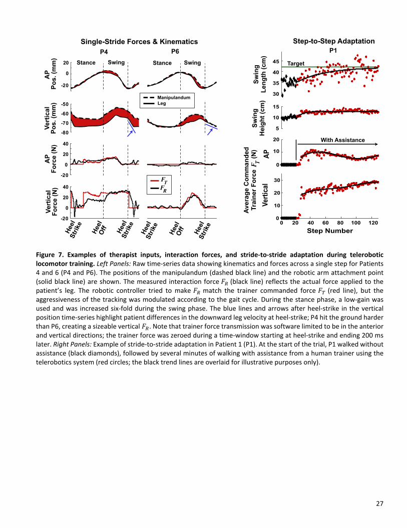
27
Figure 7. Examples of therapist inputs, interaction forces, and stride‐to‐stride adaptation during telerobotic locomotor training. Left Panels: Raw time‐series data showing kinematics and forces across a single step for Patients 4 and 6 (P4 and P6). The positions of the manipulandum (dashed black line) and the robotic arm attachment point (solid black line) are shown. The measured interaction force 𝐹 (black line) reflects the actual force applied to the patient’s leg. The robotic controller tried to make 𝐹 match the trainer commanded force 𝐹 (red line), but the aggressiveness of the tracking was modulated according to the gait cycle. During the stance phase, a low‐gain was used and was increased six‐fold during the swing phase. The blue lines and arrows after heel‐strike in the vertical position time‐series highlight patient differences in the downward leg velocity at heel‐strike; P4 hit the ground harder than P6, creating a sizeable vertical 𝐹 . Note that trainer force transmission was software limited to be in the anterior and vertical directions; the trainer force was zeroed during a time‐window starting at heel‐strike and ending 200 ms later. Right Panels: Example of stride‐to‐stride adaptation in Patient 1 (P1). At the start of the trial, P1 walked without assistance (black diamonds), followed by several minutes of walking with assistance from a human trainer using the telerobotics system (red circles; the black trend lines are overlaid for illustrative purposes only).
-20
0
20
-70
-60
-50
-80
40
20
0
-20
-20
40
20
0
AP
P
os
. (m
m)
Ve
rtic
al
Po
s.
(mm
)A
PF
orc
e (
N)
Ve
rtic
al
Fo
rce
(N
)
Stance Swing Stance Swing
P4 P6
Single-Stride Forces & Kinematics
triHeel
Ske
triHeel
Ske
Of
Heel
f
triHeel
Ske
triHeel
Ske
Of
Heel
fFT
FR
30
35
40
45
5
10
15
0
10
20
20 40 60 80 100 120
Step Number
0
10
20
30
Sw
ing
H
eig
ht
(cm
)S
win
gL
en
gth
(c
m)
With Assistance
Target
AP
Ve
rtic
al
Av
era
ge
Co
mm
an
de
dTra
ine
r F
orc
e
(N)
FT
Step-to-Step Adaptation
P1
0
Manipulandum
Leg

28
Figure 8. Adaptation and retention across six days of telerobotic locomotor training for six patients who have survived strokes (P1‐P6). The black bars show the swing kinematics at the start of each day without assistance (average ± std. across steps for the first no‐assistance trial). The red lines show the average swing kinematics at the end of the day with assistance from a trainer using the telerobotics system (average ± std. across steps for the last trial). P1‐P3 received assistance from Trainer 1 (*except on Day 5 Trainer 2 assisted); P4‐P6 received assistance from Trainer 2. ⴕP3 received resistance from Trainer 1 on Day 4. The step length target is indicated by the green horizontal line. For P1 the target was increased after the first day; for P2 the target was calculated using the third no‐assistance trial. T1 = Trainer 1; T2 = Trainer 2.
0
20
40
0
5
10
15
P1
Swing Length
P2 P3
P4 P5 P6
1 2 3 4 5 6
Day1 2 3 4 5 6
Day1 2 3 4 5 6
Day
1 2 3 4 5 6
Day1 2 3 4 5 6
Day1 2 3 4 5 6
Day
1 2 3 4 5 6
Day
1 2 3 4 5 6
Day1 2 3 4 5 6
Day
1 2 3 4 5 6
Day1 2 3 4 5 6
Day
1 2 3 4 5 6
Day
0
20
40
Dis
pla
cem
en
t (c
m)
0
5
10
15
P1 P2 P3
P4 P5 P6
Swing HeightT
1T
2
Dis
pla
cem
en
t (c
m)
Dis
pla
cem
en
t (c
m)
Dis
pla
cem
en
t (c
m)
*T2
T1
T2
*T2*T2
*T2
*T2*T2

29
Figure 9. Average sagittal‐plane leg trajectories and trainer forces for six patients who have survived strokes (P1‐P6) across six practice days. For each patient, the black trajectories on the left show the average non‐assisted leg trajectory during the initial trial of each practice day. The red trajectories in the right column show the average leg trajectory for the last trial of each day, in which the patient received assistance from a trainer using the telerobotic system. The red arrows show the average commanded trainer forces (𝐹 ) applied from heel‐off to heel‐strike. Trainer force transmission was software limited to be in the anterior and vertical directions, except P3 on Day 4, who received resistive forces.
P2
30 N
P1
No Assist Telerobotic
Assist
Day 1
Day 2
Day 3
Day 4
Day 6
P3
P5P4
Day 1
Day 2
Day 3
Day 4
Day 5
Day 6
10 cm
P6
No Assist No Assist
No Assist No Assist No Assist
Resistance
Telerobotic
Assist
Telerobotic
Assist
Telerobotic
Assist
Telerobotic
AssistTelerobotic
Assist
Day 5

Figures
Figure 1
Overview of telerobotics locomotor rehabilitation approach. A: The patient walks on a treadmill with alarge robot arm connected to their right lower leg using a magnetic attachment. Meanwhile, a humantrainer holds a small robot manipulandum, which shadows the scaleddown motion of the large robotarm and allows the trainer to feel and manipulate the patient’s gait in realtime (i.e., teleoperation). B: Acloseup view of the magnetic attachment (detached for clarity). C: A visual display is provided to thetrainer, which shows the patient’s gait kinematics and taskrelated overlays (e.g., gait target, forcemagnitudes, etc.). The white and green vertical lines show the actual and target swing lengths,respectively. The white arrow shows the trainer’s applied force

Figure 2
Flowchart detailing operation of the telerobotics system. A large robotic arm is magnetically attached to apatient’s leg. The motion of the patient’s leg is measured using the robotic arm’s sensors. A scaleddownversion of the patient’s motion is haptically rendered using a small robotic manipulandum, which is heldby a human trainer. The trainer can provide assistance (or resistance) in realtime by de�ecting themanipulandum at an appropriate point in the gait cycle; the amount of force transmitted is proportionalto the de�ection (within limits).

Figure 3
Trainer force transmission algorithm. A trainer can apply force to a patient by de�ecting amanipulandum, which follows a scaleddown version of the patient’s leg motion in realtime. Thetrainer’s force is ampli�ed and scales with the amount of de�ection. Note the gray shading showing thedeadband and the red shading showing the range of transmitted forces are not drawn to scale.

Figure 4
Evaluation of transparency in unimpaired participants: raw data. Trajectories and interaction forces forthe right lower leg for two unimpaired participants (U1 & U2) during treadmill locomotion with andwithout a robotic arm attached to the leg. In a control condition (no robot; NR), the subjects walkedwithout the robot attached their leg (top; black trajectories). In the other condition (red trajectories), arobotic arm was attached close to the centerofmass of the leg (with robot; WR), and the robot wasprogrammed to follow the leg and not interfere. The measured interaction forces (FR) are shown from the

reference frame of the subjects. A positive anteriorposterior (AP) force means the robotic arm waspushing anteriorly on the leg; a positive vertical force means that the robotic arm was pushing upwardson the leg. Force data are not interpolated to the stepcycle; therefore, the timing of the swing cycle variesslightly from steptostep (hence, the gradient shading).
Figure 5
Evaluation of transparency in unimpaired participants: summary statistics. Step kinematics and robotinteraction forces (FR) while two unimpaired subjects (U1 & U2) walked on a treadmill with (with robot;WR; red) and without (no robot; WR; black) a robotic arm attached to their legs. When the robotic arm wasattached, it was programmed to follow along and not interfere with the subjects’ locomotion. The errorbars denote one standard deviation across steps for the last two minutes of walking.

Figure 6
Trainer and robotic armapplied forces across six days of telerobotic locomotor training for six patientswho have survived strokes (P1P6). The red bars show the average commanded trainer force FT (average± std. across steps) for the last trial of each day. This force is an ampli�ed version of the force computedfrom the de�ection of a manipulandum held by the trainer. The black bars show the average force appliedto the patients’ affected legs by the robotic arm (FR). This force was measured by a force transducer on
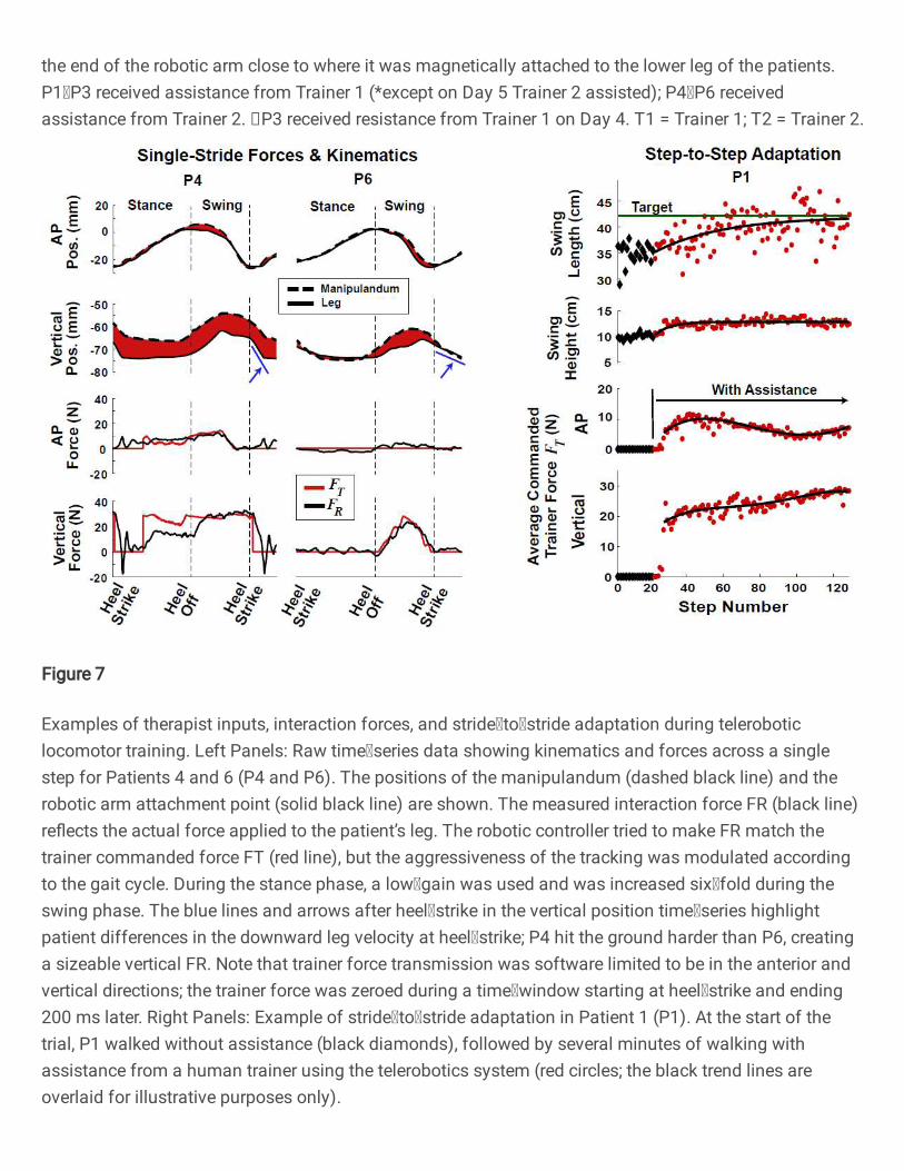
the end of the robotic arm close to where it was magnetically attached to the lower leg of the patients.P1P3 received assistance from Trainer 1 (*except on Day 5 Trainer 2 assisted); P4P6 receivedassistance from Trainer 2. P3 received resistance from Trainer 1 on Day 4. T1 = Trainer 1; T2 = Trainer 2.
Figure 7
Examples of therapist inputs, interaction forces, and stridetostride adaptation during teleroboticlocomotor training. Left Panels: Raw timeseries data showing kinematics and forces across a singlestep for Patients 4 and 6 (P4 and P6). The positions of the manipulandum (dashed black line) and therobotic arm attachment point (solid black line) are shown. The measured interaction force FR (black line)re�ects the actual force applied to the patient’s leg. The robotic controller tried to make FR match thetrainer commanded force FT (red line), but the aggressiveness of the tracking was modulated accordingto the gait cycle. During the stance phase, a lowgain was used and was increased sixfold during theswing phase. The blue lines and arrows after heelstrike in the vertical position timeseries highlightpatient differences in the downward leg velocity at heelstrike; P4 hit the ground harder than P6, creatinga sizeable vertical FR. Note that trainer force transmission was software limited to be in the anterior andvertical directions; the trainer force was zeroed during a timewindow starting at heelstrike and ending200 ms later. Right Panels: Example of stridetostride adaptation in Patient 1 (P1). At the start of thetrial, P1 walked without assistance (black diamonds), followed by several minutes of walking withassistance from a human trainer using the telerobotics system (red circles; the black trend lines areoverlaid for illustrative purposes only).

Figure 8
Adaptation and retention across six days of telerobotic locomotor training for six patients who havesurvived strokes (P1P6). The black bars show the swing kinematics at the start of each day withoutassistance (average ± std. across steps for the �rst noassistance trial). The red lines show the averageswing kinematics at the end of the day with assistance from a trainer using the telerobotics system(average ± std. across steps for the last trial). P1P3 received assistance from Trainer 1 (*except on Day 5Trainer 2 assisted); P4P6 received assistance from Trainer 2. P3 received resistance from Trainer 1 onDay 4. The step length target is indicated by the green horizontal line. For P1 the target was increasedafter the �rst day; for P2 the target was calculated using the third noassistance trial. T1 = Trainer 1; T2 =Trainer 2.

Figure 9
Average sagittalplane leg trajectories and trainer forces for six patients who have survived strokes (P1P6) across six practice days. For each patient, the black trajectories on the left show the average nonassisted leg trajectory during the initial trial of each practice day. The red trajectories in the right columnshow the average leg trajectory for the last trial of each day, in which the patient received assistance froma trainer using the telerobotic system. The red arrows show the average commanded trainer forces (FT)applied from heeloff to heelstrike. Trainer force transmission was software limited to be in the anteriorand vertical directions, except P3 on Day 4, who received resistive forces.