Explanation for Traceability of the Easy Automotive Modules - Infineon
17
Electric Drive Train Easy Automotive Modules Application Note Explanation for Traceability of the Easy Automotive Modules AN2011-11 Revison 1.0
Transcript of Explanation for Traceability of the Easy Automotive Modules - Infineon
Electr ic Dr ive Train
Easy Automotive Modules
Appl icat ion Note Explanation for Traceability of the Easy Automotive Modules
AN2011-11 Revison 1.0

Edition Revison 1.0
Published by Infineon Technologies AG 81726 Munich, Germany
© 2012 Infineon Technologies AG
All Rights Reserved.
LEGAL DISCLAIMER
THE INFORMATION GIVEN IN THIS DOCUMENT IS GIVEN AS A HINT FOR THE IMPLEMENTATION OF THE INFINEON TECHNOLOGIES COMPONENT ONLY AND SHALL NOT BE REGARDED AS ANY DESCRIPTION OR WARRANTY OF A CERTAIN FUNCTIONALITY, CONDITION OR QUALITY OF THE INFINEON TECHNOLOGIES COMPONENT. THE RECIPIENT OF THIS DOCUMENT MUST VERIFY ANY FUNCTION DESCRIBED HEREIN IN THE REAL APPLICATION. INFINEON TECHNOLOGIES HEREBY DISCLAIMS ANY AND ALL WARRANTIES AND LIABILITIES OF ANY KIND (INCLUDING WITHOUT LIMITATION WARRANTIES OF NON-INFRINGEMENT OF INTELLECTUAL PROPERTY RIGHTS OF ANY THIRD PARTY) WITH RESPECT TO ANY AND ALL INFORMATION GIVEN IN THIS DOCUMENT.
Information
For further information on technology, delivery terms and conditions and prices, please contact the nearest Infineon Technologies Office (www.infineon.com).
Warnings
Due to technical requirements, components may contain dangerous substances. For information on the types in question, please contact the nearest Infineon Technologies Office.
Infineon Technologies components may be used in life-support devices or systems only with the express written approval of Infineon Technologies, if a failure of such components can reasonably be expected to cause the failure of that life-support device or system or to affect the safety or effectiveness of that device or system. Life support devices or systems are intended to be implanted in the human body or to support and/or maintain and sustain and/or protect human life. If they fail, it is reasonable to assume that the health of the user or other persons may be endangered.
Easy-Automotive Modules Explanation for Traceability
Application Note 3 AN2011-11 Explanation for Traceability of the Easy-Automotive Modules
Document Change History
Date Version Changed By Change Description
11-2011 1.0 T. Reiter (IFAG ATV OPEV AE) Initial Version
We Listen to Your Comments
Is there any information in this document that you feel is wrong, unclear or missing? Your feedback will help us to continuously improve the quality of this document. Please send your proposal (including a reference to this document) to:
Trademarks of Infineon Technologies AG
AURIX™, BlueMoon™, COMNEON™, C166™, CROSSAVE™, CanPAK™, CIPOS™, CoolMOS™, CoolSET™, CORECONTROL™, DAVE™, EasyPIM™, EconoBRIDGE™, EconoDUAL™, EconoPACK™, EconoPIM™, EiceDRIVER™, EUPEC™, FCOS™, HITFET™, HybridPACK™, ISOFACE™, I²RF™, IsoPACK™, MIPAQ™, ModSTACK™, my-d™, NovalithIC™, OmniTune™, OptiMOS™, ORIGA™, PROFET™, PRO-SIL™, PRIMARION™, PrimePACK™, RASIC™, ReverSave™, SatRIC™, SIEGET™, SINDRION™, SMARTi™, SmartLEWIS™, TEMPFET™, thinQ!™, TriCore™, TRENCHSTOP™, X-GOLD™, XMM™, X-PMU™, XPOSYS™.
Easy-Automotive Modules Explanation for Traceability
Table of Contents Page
Application Note 4 AN2011-11 Explanation for Traceability of the Easy-Automotive Modules
1 Introduction ................................................................................................................................... 5
2 Explanation of the Module Markings .......................................................................................... 6 2.1 Module appearance ........................................................................................................................ 6 2.1.1 Type Designation ............................................................................................................................ 7 2.1.2 Module Datecode ............................................................................................................................ 8 2.1.3 Module Serial Number .................................................................................................................... 8 2.1.4 Data matrix (DMX) code .................................................................................................................. 8 2.1.4.1 Content DMX Code on the Module front ......................................................................................... 8 2.1.4.2 Content DMX Code on the Module back ........................................................................................ 9 2.1.5 UL mark ........................................................................................................................................... 9 2.1.6 GND sign ......................................................................................................................................... 9
3 Explanation of the Tray Label ...................................................................................................... 9 3.1 Tray Label Appearance ................................................................................................................. 10 3.1.1 Production Lot ............................................................................................................................... 11 3.1.2 Sales Product Number .................................................................................................................. 11 3.1.3 ESD Symbol .................................................................................................................................. 11 3.1.4 Lead free symbol ........................................................................................................................... 11 3.1.5 Tray Datecode ............................................................................................................................... 11 3.1.6 Backend Construction Number ..................................................................................................... 11 3.1.7 Tray Serial 1 .................................................................................................................................. 11 3.1.8 Printer ID ....................................................................................................................................... 12 3.1.9 Tray DMX ...................................................................................................................................... 12 3.1.10 Tray content numbers ................................................................................................................... 12 3.1.11 Tray Serial 2 .................................................................................................................................. 12
4 Implemented traceability measures in Easy Automotive ....................................................... 13
5 Continuing the traceability at customer side ........................................................................... 14
6 References ................................................................................................................................... 16

Easy-Automotive Modules Explanation for Traceability Introduction
Application Note 5 AN2011-11 Explanation for Traceability of the Easy-Automotive Modules
1 Introduction
The automotive components and systems are becoming more and more complex. Furthermore, the number of components in a car also increases steadily and thus the likelyhood of a product failure. It is obvious that safety should never be compromised. But also product failures in non-safety critical functions lead to displeased end-customers and a lost of reputation in case of public product recalls, which is often not quantifiably in cost. Therefore, it is an absolutely must in the automotive industry to avoid product failures. Infineons answer is a living automotive excellence program, which includes e.g. the Zero Defect Production. In order to support the lowest possible FIT (failure in time) rate in the field, preventive measures for avoiding product failures as well as reduction of failures in the field are demanded. One possibility is a seamless traceability of the production materials and manufacturing processes, which can also avoid product piracy, as materials, processes and equipment can be traced back to the origin.
The Easy Automotive power modules have implemented a considerably set of traceability measures. These are explained in this application note. But traceabily must not be aborted after the modules are shipped to the customer. Therefore, hints for continuing a seamless traceability on the customer side are given as well as the identification of module-IDs, tray-IDs, which is the key to achieve such a tracing functionality. Therefore, module and tray labels are explained, that the customer easily finds the right numbers and IDs for the traceability concept.
Please note that only the automotive version of the Easy power module has fully implemented the traceability measures described in this application note. See Figure 1a how to identify an Easy Automotive module.
Easy-Automotive Modules Explanation for Traceability Explanation of the Module Markings
Application Note 6 AN2011-11 Explanation for Traceability of the Easy-Automotive Modules
2 Explanation of the Module Markings
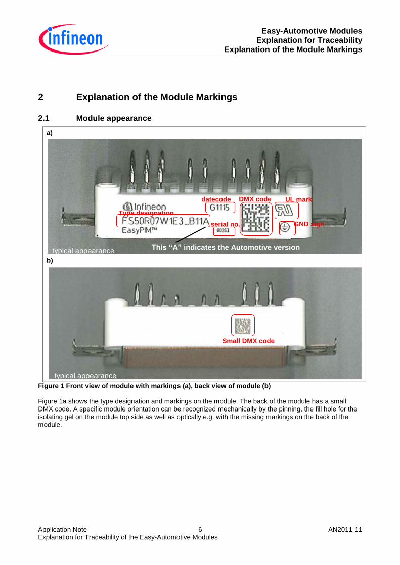
2.1 Module appearance
a)
b)
Figure 1 Front view of module with markings (a), back view of module (b) Figure 1a shows the type designation and markings on the module. The back of the module has a small DMX code. A specific module orientation can be recognized mechanically by the pinning, the fill hole for the isolating gel on the module top side as well as optically e.g. with the missing markings on the back of the module.
typical appearance
typical appearance
Type designation
datecode
serial no.
DMX code UL mark
GND sign
This “A” indicates the Automotive version
Small DMX code
Easy-Automotive Modules Explanation for Traceability Explanation of the Module Markings
Application Note 7 AN2011-11 Explanation for Traceability of the Easy-Automotive Modules
2.1.1 Type Designation
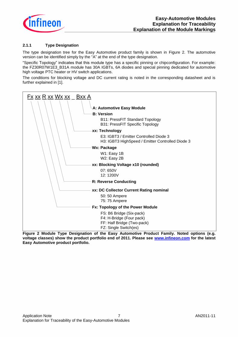
The type designation tree for the Easy Automotive product family is shown in Figure 2. The automotive version can be identified simply by the “A” at the end of the type designation.
“Specific Topology” indicates that this module type has a specific pinning or chipconfiguration. For example: the FZ30R07W1E3_B31A module has 30A IGBTs, 6A diodes and special pinning dedicated for automotive high voltage PTC heater or HV switch applications.
The conditions for blocking voltage and DC current rating is noted in the corresponding datasheet and is further explained in [1].
Fx xx R xx Wx xx _ Bxx A
A: Automotive Easy Module
B: Version
B11: PressFIT Standard Topology
B31: PressFIT Specific Topology
xx: Technology
E3: IGBT3 / Emitter Controlled Diode 3
H3: IGBT3 HighSpeed / Emitter Controlled Diode 3
xx: Blocking Voltage x10 (rounded)
07: 650V
12: 1200V
R: Reverse Conducting
xx: DC Collector Current Rating nominal
Fx: Topology of the Power Module
50: 50 Ampere
75: 75 Ampere
FS: B6 Bridge (Six-pack)
F4: H-Bridge (Four pack)
FF: Half Bridge (Two-pack)
FZ: Single Switch(es)
Wx: Package
W1: Easy 1B
W2: Easy 2B
Figure 2 Module Type Designation of the Easy Automotive Product Family. Noted options (e.g. voltage classes) show the product portfolio end of 2011. Please see www.infineon.com for the latest Easy Automotive product portfolio.

Easy-Automotive Modules Explanation for Traceability Explanation of the Module Markings
Application Note 8 AN2011-11 Explanation for Traceability of the Easy-Automotive Modules
2.1.2 Module Datecode
The datecode on the power module has the following format: GYYWW
G: This letter indicates that the product is “green” / RoHS conform. The meaning is quite similar to the lead free symbol on the module tray (see section 3.1.4).
YY: Production Year
WW: Production Week
G1115 of the sample in Figure 1 means that the module production started in calender week 15 in year 2011.
2.1.3 Module Serial Number
The serial number is a 5 digit number: xxxxx
It starts from 0 for each production lot. Please note that serial number alone is not unique! Only the production lot & the serial number of the power module gives a bijective ID. These numbers are stored in the “large” DMX code on the front side of the module housing. See section 2.1.4 for explanation of the DMX code contents.
2.1.4 Data matrix (DMX) code
A data matrix code (DMX code) is a two-dimensional barcode with an improved failure correction and lower space requirements compared to the 1 dimensional barcodes (e.g. code 128). The DMX code appearance and reading is normed in following standards: ISO/IEC 16022 and ISO/IEC24720.
Figure 3 Data matrix (DMX) code sample
Figure 3 shows a sample DMX code, which is printed on an Easy Automotive module. The selection edge can be seen in the lower left corner. The code on the housing represents a bijective module-ID (number).
2.1.4.1 Content DMX Code on the Module front
The information linked to this module-ID/number contains:
Content of the Code Digit
Module serial number 1-5
Module material number 6-11
Production order number 12-19
Datecode (production year) 20-21
Datecode (production week) 22-23

Easy-Automotive Modules Explanation for Traceability Explanation of the Tray Label
Application Note 9 AN2011-11 Explanation for Traceability of the Easy-Automotive Modules
Compared to the alphanumeric datecode and serial number printed on the housing. The combination of serial number, material number and datecode in the DMX allows a bijective module ID for several billion modules.
2.1.4.2 Content DMX Code on the Module back
The small DMX code on the module back side is only for Infineon internal processes. It contains no specific information for the customer, as all data is linked to the larger DMX code on the module front side.
2.1.5 UL mark
The UL mark on the housing indicates that the Easy power module is an UL Recognized Component. The product family was tested under the UL Standard for Safety for Electrically Isolated Semiconductor Devices, UL 1557, Fourth Edition, dated June 14, 2006.
The insulation system to ground of these devices has been successfully tested for an isolation voltage of 2500 V. The maximum operation junction temperature is 150°C.
2.1.6 GND sign
The GND sign indicates that the module has a basic insulation (class 1 according to IEC 61140) and has to be mounted to a chassis with earth/neutral potential.
3 Explanation of the Tray Label
The label on the tray is fixed in a way that the important data is visible both from the top side and front side of the tray. This is important, as the trays are normally stored on stocks as shown in Figure 4
Figure 4 A stock of Easy module trays.

Easy-Automotive Modules Explanation for Traceability Explanation of the Tray Label
Application Note 10 AN2011-11 Explanation for Traceability of the Easy-Automotive Modules
3.1 Tray Label Appearance
Figure 5 shows a typical tray label. The folding edge indicates which information can be seen on the top side and front side of the module tray. As shown in Figure 4 the front side is visible even if the trays are stored in a stack.
Figure 5 Tray label (typical appearance).
typical appearance typical appearance This “A” indicates the Automotive version
ESD sign
Production Lot
Pb free
symbol
Sales product number
Date code Quantity
Backend construction number
Printer ID
Tray DMX
Tray content numbers
Tray Serial 2
Tray Serial 1
folding edge
Easy-Automotive Modules Explanation for Traceability Explanation of the Tray Label
Application Note 11 AN2011-11 Explanation for Traceability of the Easy-Automotive Modules
3.1.1 Production Lot
The production lot starts with (1T) as identifier followed by a 8 digit alphanumeric code. Typically 1X at the beginning indicates an Easy 1B and 2X an Easy 2B automotive module.
3.1.2 Sales Product Number
The sales product number starts with (1P) as identifier. SP Numbers indicates a productive part. SA numbers are used for engineering samples. However, not productive parts have a different label tray format and do not have traceability measures implemented.
3.1.3 ESD Symbol
The warning symbol indicates that the devices in the tray are susceptible to electrostatic discharge.
The power modules are rated in the ESD sensitivity level (per AEC-101 specification) as follows:
Human Body Model HMB: ≥ 8 kV
Charged device Model CDM: ≥ 1 kV
3.1.4 Lead free symbol
The symbol indicates that the devices in the tray do not contain lead. Furthermore the Easy Automotive Module is RoHS conform, which means, that it does not contain any of the six substances: lead, mercury, cadmium, hexavalent chromium, poly-brominatedbiphenyls or polybrominated diphenyl ethers, in quantities exceeding maximum concentration values given in the RoHS standard.
3.1.5 Tray Datecode
The datecode on the tray has the following format: YYWW
YY: Production Year
WW: Production Week
This code is given at the beginning of the production lot and thus is similar to the modules inside the tray. Exception is a mixed production lot where two different module datecodes can appear in a tray.
3.1.6 Backend Construction Number
The 8 digit construction number is an Infineon internal number only, which is used in the production. It contains no relevant data for the customer.
3.1.7 Tray Serial 1
This barcode is a composition of the backend construction number, the production lot and the tray serial number. In this example it contains the following data:
X95056609 1T2X0003E0 S754389
This number is bijective and can be used for implementation of tracability measures. However, this barcode may be sometimes not readable e.g. if several trays are stored in a stack. Therefore, this content is also stored in a barcode on the tray front side (see subsection 3.1.11).

Easy-Automotive Modules Explanation for Traceability Explanation of the Tray Label
Application Note 12 AN2011-11 Explanation for Traceability of the Easy-Automotive Modules
3.1.8 Printer ID
This alphanumeric number is the ID of the labelprinter. In case the label print has failures (e.g. problems at the readout) the ID gives the possibility to trace this issue back to a certain label printer.
3.1.9 Tray DMX
This DMX code on the tray is a composition of all numbers stored the other bar codes. In this example it contains the following data (not relevant data is indicated with “#”):
∆## X95056609 1T2X0003E0 9D1139 Q15 1PSP000865130 ### ### S754389∆
- Backend construction number
- Production lot datecode
- Quantity
- Sales product number
- Tray serial number
This number is bijective (similar to tray serial 1 and 2) and can be used for implementation of tracability measures.
3.1.10 Tray content numbers
The tray content numbers is a composition of different numbers as shown in Figure 6. The “identifiers” in the brackets ensure, that the following number can be linked to a specific content in the software systems. After the (240) identifier follows the material number in this example. The material number is an Infineon internal representative for the corresponding module designation (FS75R07W2E3_B11A). After the (10) identifier follows the production lot, the quantity and a three digit serial number.
(240)35375(10)2X0003E0(37)15(90)438
Serial No.
Identifier
Quantity
Production Lot
Identifier
Identifier
Material No.
Identifier
Figure 6 Tray content numbers (typical appearance).
3.1.11 Tray Serial 2
This barcode a composition of the backend construction number, the production lot, the tray serial number, date code and quantity.
This code is quite similar to the tray serial number 1 and is bijective. It can be used for implementation of tracability measures. Compared to the tray serial number 1, this barcode is also visible if several trays are stored in a stack.
Easy-Automotive Modules Explanation for Traceability Implemented traceability measures in Easy Automotive
Application Note 13 AN2011-11 Explanation for Traceability of the Easy-Automotive Modules
4 Implemented traceability measures in Easy Automotive
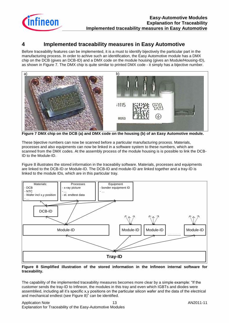
Before traceability features can be implemented, it is a must to identify bijectively the particular part in the manufacturing process. In order to achive such an identification, the Easy Automotive module has a DMX chip on the DCB (gives an DCB-ID) and a DMX code on the module housing (gives an Module/Housing-ID), as shown in Figure 7. The DMX chip is quite similar to printed DMX code - it simply has a bijective number.
a)
b)
Figure 7 DMX chip on the DCB (a) and DMX code on the housing (b) of an Easy Automotive module. These bijective numbers can now be scanned before a particular manufacturing process. Materials, processes and also equipments can now be linked in a software system to these numbers, which are scanned from the DMX codes. At the assembly process of the module housing is is possible to link the DCB-ID to the Module-ID. Figure 8 illustrates the stored information in the traceabiliy software. Materials, processes and equipments are linked to the DCB-ID or Module-ID. The DCB-ID and module-ID are linked together and a tray-ID is linked to the module IDs, which are in this particular tray.
DCB-ID
Module-ID
Tray-ID
Materials:
- DCB
- NTC
- Wafer incl x,y position
- …
Equipment
- bonder equipment ID
- …
Processes
- x-ray picture
- ...
- el. endtest data
Module-ID Module-ID Module-ID
Figure 8 Simplified illustration of the stored information in the Infineon internal software for traceability.
The capability of the implemented traceability measures becomes more clear by a simple example: “If the customer sends the tray-ID to Infineon, the modules in this tray and even which IGBTs and diodes were assemblied, including all it’s specific x,y positions on the particular silicon wafer and the data of the electrical and mechanical endtest (see Figure 8)” can be identified.
Easy-Automotive Modules Explanation for Traceability Continuing the traceability at customer side
Application Note 14 AN2011-11 Explanation for Traceability of the Easy-Automotive Modules
5 Continuing the traceability at customer side
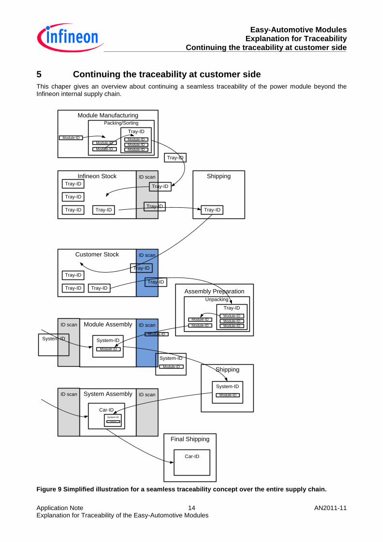
This chaper gives an overview about continuing a seamless traceability of the power module beyond the Infineon internal supply chain.
Module Manufacturing
Infineon Stock ID scan
Tray-ID
Tray-ID
Tray-ID
Tray-ID
Tray-ID
Tray-ID
Shipping
Packing/Sorting
Module-ID
Module-ID
Tray-ID
Module-ID
Tray-ID
Module-ID
Module-ID
Module-ID
Customer Stock ID scan
Tray-ID
Tray-ID
Tray-ID
Tray-ID
Module Assembly ID scan
Assembly Preparation
Unpacking
Module-ID
Module-ID
Tray-ID
Module-ID
Module-ID
Module-ID
Tray-ID
Tray-ID
Shipping
ID scan
System-IDModule-ID
System-ID
Module-ID
System-ID
Module-ID
System-ID
Module-ID
System Assembly ID scanID scan
Car-ID
System-ID
Module-ID
Final Shipping
Car-ID
Figure 9 Simplified illustration for a seamless traceability concept over the entire supply chain.
Easy-Automotive Modules Explanation for Traceability Continuing the traceability at customer side
Application Note 15 AN2011-11 Explanation for Traceability of the Easy-Automotive Modules
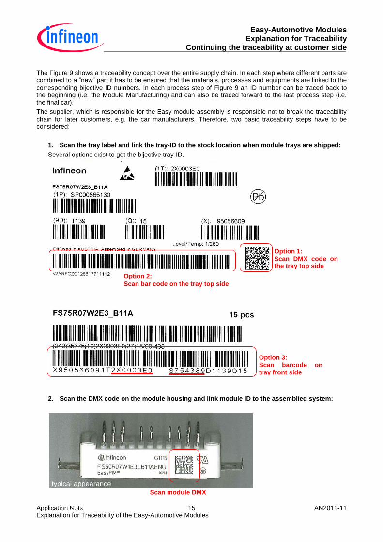
The Figure 9 shows a traceability concept over the entire supply chain. In each step where different parts are combined to a “new” part it has to be ensured that the materials, processes and equipments are linked to the corresponding bijective ID numbers. In each process step of Figure 9 an ID number can be traced back to the beginning (i.e. the Module Manufacturing) and can also be traced forward to the last process step (i.e. the final car).
The supplier, which is responsible for the Easy module assembly is responsible not to break the traceability chain for later customers, e.g. the car manufacturers. Therefore, two basic traceability steps have to be considered:
1. Scan the tray label and link the tray-ID to the stock location when module trays are shipped:
Several options exist to get the bijective tray-ID.
2. Scan the DMX code on the module housing and link module ID to the assemblied system:
typical appearance
Scan module DMX
typical appearance
Option 3: Scan barcode on tray front side
Option 1: Scan DMX code on the tray top side
Option 2:
Scan bar code on the tray top side

Easy-Automotive Modules Explanation for Traceability References
Application Note 16 AN2011-11 Explanation for Traceability of the Easy-Automotive Modules
The first step, where the tray-ID is scanned is highly recommended. It gives the opportunity to identify which particular modules are still on stock and are not assemblied yet.
The second step is mandatory for the traceability, where the scanned Module ID is linked to the assemblied system ID.
6 References
The referenced application notes can be found at http://www.infineon.com
[1] Infineon Application Note AN2010-09, “Explanation of Technical Information”.
[2] Infineon Application Note AN2009-01, “Easy PressFIT Assembly Instructions”.

w w w . i n f i n e o n . c o m
Published by Infineon Technologies AG