Experimental Study on Enhanced Condensate Recovery by Gas ...
15
Research Article Experimental Study on Enhanced Condensate Recovery by Gas Injection in Yaha Condensate Gas Reservoir Yiming Wu, 1 Kun Yao, 1 Yan Liu, 1 Xiangyun Li, 2 Mimi Wu, 1 Ronghong Cheng, 1 and Bo Wang 3 1 Research Institute of Exploration and Exploitation, Petro-China Tarim Oilfield Company, Korla 841000, China 2 CNPC USA Corporation, Beijing 100028, China 3 Petroleum Systems Engineering, Faculty of Engineering and Applied Science, University of Regina, Regina, Saskatchewan S4S 0A2, Canada Correspondence should be addressed to Bo Wang; [email protected] Received 8 August 2021; Revised 8 September 2021; Accepted 20 September 2021; Published 14 October 2021 Academic Editor: Jinjie Wang Copyright © 2021 Yiming Wu et al. This is an open access article distributed under the Creative Commons Attribution License, which permits unrestricted use, distribution, and reproduction in any medium, provided the original work is properly cited. A condensate gas reservoir is an important special oil and gas reservoir between oil reservoir and natural gas reservoir. Gas injection production is the most commonly used development method for this type of gas reservoir, but serious retrograde condensation usually occurs in the later stages of development. To improve the recovery efficiency of condensate oil in the middle and late stages of production of a condensate gas reservoir, a gas injection parameter optimization test study was carried out, taking the Yaha gas condensate reservoir in China as an example. On the premise that the physical experimental model and key parameters met the actual conditions of the formation, the injection method, injection medium, injection- production ratio, and other parameters of the condensate gas reservoir were studied. Research on the injection method showed that the top injection method had a lower gas-oil ratio and higher condensate oil recovery. The study of injection medium showed that the production effect of carbon dioxide (CO 2 ) injection was the best injection medium, and the maximum recovery rate of condensate oil was 95.11%. The injection-production ratio study showed that the injection-production ratio was approximately inversely proportional to the recovery factor of condensate gas and approximately proportional to the recovery factor of condensate oil. When the injection-production ratio was 1 : 1, the maximum recovery rate of condensate oil was 83.31%. In summary, in the later stage of gas injection development of the Yaha condensate gas reservoir, it was recommended to choose the development plan of CO 2 injection at the top position with an injection-production ratio of 1 : 1. This research can not only provide guidance for the later formulation of gas injection plans for Yaha condensate gas reservoirs but also lay a foundation for the research of gas injection migration characteristics of other condensate gas reservoirs. 1. Introduction With the continuous improvement of the level of explora- tion technology and exploration degree at home and abroad, the proportion of condensate gas reservoirs discovered is increasing year by year. Therefore, condensate gas fields occupy a particularly important position in the development of gas fields in the world. Condensate gas reservoir is differ- ent from ordinary oil reservoir or gas reservoir; it has the dual characteristics of oil reservoir and gas reservoir [1]. Due to the special fluid phase characteristics, its extraction technology and development difficulty are much more com- plicated than general gas reservoirs and oil reservoirs [2–4]. During the development of condensate gas reservoirs, when the reservoir pressure is lower than the dew point pressure, serious retrograde condensation will occur in the reservoir. In other words, condensate oil will separate out of the gas phase and accumulate in a large amount in the near- wellbore zone, which will block the original seepage pores, thereby reducing the final recovery rate of condensate gas and condensate oil [5–9]. Compared with natural gas, condensate oil has extremely high economic value. At present, there are two main methods to improve the recovery rate of condensate Hindawi Geofluids Volume 2021, Article ID 7698970, 15 pages https://doi.org/10.1155/2021/7698970
Transcript of Experimental Study on Enhanced Condensate Recovery by Gas ...

Research ArticleExperimental Study on Enhanced Condensate Recovery by GasInjection in Yaha Condensate Gas Reservoir
Yiming Wu,1 Kun Yao,1 Yan Liu,1 Xiangyun Li,2 Mimi Wu,1 Ronghong Cheng,1
and Bo Wang 3
1Research Institute of Exploration and Exploitation, Petro-China Tarim Oilfield Company, Korla 841000, China2CNPC USA Corporation, Beijing 100028, China3Petroleum Systems Engineering, Faculty of Engineering and Applied Science, University of Regina, Regina,Saskatchewan S4S 0A2, Canada
Correspondence should be addressed to Bo Wang; [email protected]
Received 8 August 2021; Revised 8 September 2021; Accepted 20 September 2021; Published 14 October 2021
Academic Editor: Jinjie Wang
Copyright © 2021 Yiming Wu et al. This is an open access article distributed under the Creative Commons Attribution License,which permits unrestricted use, distribution, and reproduction in any medium, provided the original work is properly cited.
A condensate gas reservoir is an important special oil and gas reservoir between oil reservoir and natural gas reservoir. Gasinjection production is the most commonly used development method for this type of gas reservoir, but serious retrogradecondensation usually occurs in the later stages of development. To improve the recovery efficiency of condensate oil in themiddle and late stages of production of a condensate gas reservoir, a gas injection parameter optimization test study wascarried out, taking the Yaha gas condensate reservoir in China as an example. On the premise that the physical experimentalmodel and key parameters met the actual conditions of the formation, the injection method, injection medium, injection-production ratio, and other parameters of the condensate gas reservoir were studied. Research on the injection method showedthat the top injection method had a lower gas-oil ratio and higher condensate oil recovery. The study of injection mediumshowed that the production effect of carbon dioxide (CO2) injection was the best injection medium, and the maximumrecovery rate of condensate oil was 95.11%. The injection-production ratio study showed that the injection-production ratiowas approximately inversely proportional to the recovery factor of condensate gas and approximately proportional to therecovery factor of condensate oil. When the injection-production ratio was 1 : 1, the maximum recovery rate of condensate oilwas 83.31%. In summary, in the later stage of gas injection development of the Yaha condensate gas reservoir, it wasrecommended to choose the development plan of CO2 injection at the top position with an injection-production ratio of 1 : 1.This research can not only provide guidance for the later formulation of gas injection plans for Yaha condensate gas reservoirsbut also lay a foundation for the research of gas injection migration characteristics of other condensate gas reservoirs.
1. Introduction
With the continuous improvement of the level of explora-tion technology and exploration degree at home and abroad,the proportion of condensate gas reservoirs discovered isincreasing year by year. Therefore, condensate gas fieldsoccupy a particularly important position in the developmentof gas fields in the world. Condensate gas reservoir is differ-ent from ordinary oil reservoir or gas reservoir; it has thedual characteristics of oil reservoir and gas reservoir [1].Due to the special fluid phase characteristics, its extractiontechnology and development difficulty are much more com-
plicated than general gas reservoirs and oil reservoirs [2–4].During the development of condensate gas reservoirs, whenthe reservoir pressure is lower than the dew point pressure,serious retrograde condensation will occur in the reservoir.In other words, condensate oil will separate out of the gasphase and accumulate in a large amount in the near-wellbore zone, which will block the original seepage pores,thereby reducing the final recovery rate of condensate gasand condensate oil [5–9].
Compared with natural gas, condensate oil hasextremely high economic value. At present, there are twomain methods to improve the recovery rate of condensate
HindawiGeofluidsVolume 2021, Article ID 7698970, 15 pageshttps://doi.org/10.1155/2021/7698970

oil: one is continuous depletion development, and the otheris gas injection to maintain pressure. In the process of deple-tion mining, natural energy is gradually released andpressure-free replenishment system. The injectionpressure-holding mining method is to inject gaseous mediainto the reservoir to supplement the formation energy toreduce retrograde condensate damage [10–12]. Scholars athome and abroad have conducted in-depth discussions onthese two methods. For example, Jingsong et al. [13] usedreservoir numerical simulation methods to analyze the sen-sitivity of injection parameters for cyclic gas injection devel-
opment of condensate gas reservoirs, focusing on evaluatingthe impact of injection methods, gas injection timing, andinjection-production ratios on the development effects ofcondensate gas reservoirs. The results show that for conden-sate gas reservoirs rich in condensate oil and with a largeground pressure difference, the development effect of thetop cycle gas injection after depletion development to thedew point pressure is better. Dong et al. [14] took theYaha-5 condensate gas reservoir as an example. The threeproduction methods of exhaustion, water injection, and gasinjection were compared and analyzed by component
Table 1: Condensate gas reservoir parameters and content.
Category Parameter Numerical Unit
Condensate gas properties
Density 0.63~0.67 kg/m3
CO2 <1 %
N2 3~ 8 %
C1 85 %
Condensate oil properties
Density 0.78~0.83 kg/m3
Freezing point 9~ 36 °C
Sulfur content <0.12 %
Wax content 5.74~13.77 %
Wax-off point 9~ 20.5 °C
Gum and asphalt content Low content —
Formation water propertiesDensity 1.08~1.44 kg/m3
Salinity 137752~214209 mg/l
Gas reservoir properties
Condensate oil content 600~700 g/m3
Maximum reverse condensation pressure 25~30 MPa
Maximum reverse condensate volume 30 %
Table 2: Geological characteristic parameters of condensate gas reservoirs.
Reservoirlocation
Thickness(m)
Averagethickness
(m)
Porosity(%)
Averageporosity(%)
Permeability(10-3 μm2)
Averagepermeability (10-
3 μm2)
Multiple ofpermeability
Average multipleof permeability
Paleogene 0.2~ 3.4 0.9 16.4~ 21.21 17.9 120.7~ 2257.7 641.4 2.6~ 7.6 3.4
Cretaceous 0.2~ 1.6 0.5 11.2~ 18.34 16 33.6~ 233.9 89.3 2.6~ 6.2 3.4
Table 3: Experimental program.
Experimentcategory
Experimentgrouping
Experiment contentExperimentalprogram
Experimental parameters
1
1
Gas injection method
Side gas injection
Temperature:137.8°CPressure:54.94MPa
Initial pressure:60MPaInjection speed:0.2ml/min
Injection and mining method: one injection and onemining
2Bottom gasinjection
3 Shaft gas injection
2
4
Gas injection medium
CH4
5 On-site gas
6 CO2
3
7Injection-production
ratio
0.5 : 1
8 0.75 : 1
9 1 : 1
2 Geofluids

numerical simulation. The research results show that waterinjection and gas injection are better than depletion mining,and gas injection is better than water injection. In particular,the large well spacing gas injection development method cannot only delay gas channeling and improve gas injection effi-ciency but also greatly increase the degree of condensate oilrecovery. Lu [15] took Dalaoba No. 2 condensate gas reser-voir with high condensate oil content as an example. Thegas injection state and seepage mechanism are analyzed,and pilot experiments are carried out. The research resultsshow that when entering the middle and late stages of min-ing, the formation pressure drops faster, the retrograde con-densation phenomenon is serious, and the formation edgewater is active. Therefore, it is not appropriate to choosedepletion mining or water injection development in the mid-dle and late stages of mining, and gas injection and pressure-maintaining development methods should be considered. Lu[16] made a comparative analysis and summary of the cur-rent recovery methods of condensate gas fields and discussedthe strategies for optimizing gas injection productionmethods. The research results indicate that the optimizationof production system, gas injection method, and stop injec-tion time should be strengthened in the development pro-cess to improve the recovery rate of condensate gas fields.Through research, it can be found that the depletion miningcost is low and the process is relatively simple, so thismethod is widely used in the development of condensategas reservoirs. The method of gas injection to maintain pres-sure is the most important method to improve the recoveryof condensate, especially for condensate gas reservoirs withhigh condensate oil content, because injecting gas into thereservoir can not only increase the formation pressure inthe retrocondensation zone but also reduce the antievapora-tion effect of the condensate oil. Therefore, the condensateoil is more easily produced. If pressure-holding mining isnot carried out, the loss of condensate oil will even reachmore than 60% to 70% of the original reserves [17–20].
Following the above research, most foreign scholars haveconducted in-depth discussions on various issues under theconditions of gas injection. Through literature research, themethods of research problems can be roughly divided intotwo categories: one is reservoir numerical simulationmethods, and the other is experimental analysis andresearch. For numerical simulation research methods, He
et al. [21] took the condensate gas reservoir in the southernpart of Rangnar A as an example, applied phase equilibriumtheory and reservoir numerical simulation technology, andstudied the mechanism and effect of CO2 huff and puff toincrease gas well condensate production. The researchresults show that when the amount of CO2 injected is small,the capacity of CO2 vaporization and condensate is limited.To ensure the effect of CO2 huff and puff to increase oil,the periodic injection of CO2 should exceed 500 × 104m3.Hassan et al. [22] used thermochemical treatment methodsto treat the near-well zone and used reservoir simulationmethods to simulate oil and gas recovery. The researchresults show that this method can significantly improve oiland gas recovery, and the main reason for this phenomenonis that this method can reduce capillary pressure and viscos-ity of condensate oil well. Wan and Mu [23] took the EagleFord shale gas condensate gas reservoir as an example, usednumerical simulation to study the effect of carbon dioxidesteam huff and puff injection on slowing down the accumu-lation of condensate around the induced fractures, and con-ducted in-depth discussions on the molecular scale. Theresearch results show that the use of CO2 huff and puff gasinjection is more conducive to improving the recovery ofrich condensate oil. Jiang and Younis [24] used a multicom-ponent molecular simulation method to perform a numeri-cal analysis on the enhanced oil recovery of carbon dioxidesteam huff and puff in a complex fractured condensate gasreservoir. On this basis, several design elements such as thenumber of cycles and the length of the injection period inthe steam stimulation process are briefly studied. For exper-imental analysis and research methods, Feng et al. [25] tookSulige tight sandstone condensate gas reservoir in OrdosBasin as an example. Based on the results of PVT phaseexperiments, core gas injection displacement experimentswere carried out. An in-depth study of continuous gas
Figure 1: Schematic diagram of the core sample.
Table 4: Laboratory compound condensate gas composition table.
ComponentActual Laboratory
Mole fraction(mol%)
Mole fraction (mol%)
N2 3.26%79.85% CH4 81.44%
CH4 76.59%
CO2 0.62%
13.81% C2H6 13.66%
C2H6 8.90%
C3H8 1.83%
iC4 0.48%
nC4 0.71%
iC5 0.34%
nC5 0.34%
C6 0.59%
C7 1.10%
6.34% On-site condensate 4.90%
C8 1.12%
C9 0.59%
C10 0.48%
C11+ 3.05%
3Geofluids

injection, gas injection huff and puff and pulse gas injectioncondensate recovery degree, and the change characteristicsof average condensate oil saturation in the core was con-ducted, and then, the best gas injection method to improvethe condensate oil recovery was optimized. Yuan et al. [26]took the Zhongyuan Oilfield high-pressure and high-saturation condensate gas reservoir as the research object.The laboratory test study of methane (CH4) injection forenhanced oil recovery in high-pressure and high-saturatedcondensate gas reservoirs has been carried out. The researchresults show that for high-pressure and high-saturationcondensate gas fields, first depletion production to a cer-tain extent and then gas injection can also achieve higher
recovery. Hou [27] used the fully visible mercury-freehigh-temperature and high-pressure multifunctional for-mation fluid PVT analyzer to conduct an experimentalstudy on the phase behavior of an offshore high-carbondioxide condensate gas well. The experimental resultsshow that the higher the CO2 content, the higher the con-densate oil-gas-oil ratio, the greater the condensate den-sity, the higher the condensate dew point pressure, thelarger the relative volume of condensate, and the smallerthe amount of reverse condensate. Therefore, carbon diox-ide injection can improve the recovery efficiency of con-densate oil. For this conclusion, some scholars have alsoverified this view [8, 28].
Pressure gauge 1
Valve 4
Valve 3
GW
Valve 9
Valve 1 Pressure gauge 3
Pressure gauge 2 Valve 7
Computer
Dry bottle
Gas chromatographTemperature control box
Gas-liquidseparator
Gas meter
Pump 2(100D)
Valve 2
OvenPump 1(100D)
Valve 5
138ºC
Three-dimensional core holderL × W × H = (50 × 10 × 2.54) cm
54.94 MPa
Valve 5
Valve 8
Back pressure valveBPR
P
Valve 6
P
P
(a) Schematic diagram of theoretical model
High-pressure pumpInlet Outlet
Temperature control box
Confining pressure entrance
(b) Schematic diagram of actual device
Figure 2: Schematic diagram of experiment setup.
4 Geofluids

According to the above analysis, the research on improv-ing the condensate gas reservoir by gas injection and main-taining pressure mainly uses numerical simulationmethods and focuses on the elimination of retrograde con-densate theory and complex phase transition issues. Forexperimental research, most of the research focuses on theselection of gas injection medium and the discussion of gasinjection methods. There are few reports on the analysis ofkey parameters and variables in the development method
of gas injection and pressure maintenance. However, study-ing the migration mechanism and law of injected gas hasbecome an urgent problem to be solved to improve therecovery rate of gas injection in condensate gas reservoirs.In-depth study of the migration law of injected gas in con-densate gas reservoirs is the key to increasing gas injectionutilization and improving development effects.
To sum up, to research the gas injection migration char-acteristics of the Yaha condensate gas reservoir and improve
Configure condensate gas
Saturated water
Porosity test
Experiment preparation
Measurement ofexperimental parameters
Test operation
Permeability test
Saturation test
Condensate gas injectionand migration experiment
Saturated condensate gas
Cleaning and connecting equipment
Equipment leakage test
Research on gas injection method
Research on gas injection medium
Research on gas injection production ratio
Figure 3: Experiment procedure flowchart.
53.6 52.8
38.4
0.017
0.013
0.006
0
10
20
30
40
50
60
Bottom
Condensate gas
Condensate oil
Injection method
Reco
very
rate
(ml/m
in)
Top Shaft0.000
0.002
0.004
0.006
0.008
0.010
0.012
0.014
0.016
0.018
0.020
Rec
over
y ra
te (m
l/min
)
Figure 4: Histogram of the average recovery rate of different gas injection methods.
5Geofluids

the oil recovery in the later stage of the oilfield development,this research is based on the oilfield site and conductedindoor physical model experiments. First, the gas reservoirand geological profile are described. Then, the condensategas injection and migration experiments are carried out.Finally, by changing the gas injection method, gas injectionmedium, and injection-production ratio, the influence ofvarious variables on the enhanced oil recovery of condensategas injection was clarified. This research can not only pro-vide guidance for the later formulation of gas injection plansfor Yaha condensate gas reservoirs but also lay a foundationfor the research of gas injection migration characteristics ofother condensate gas reservoirs.
2. Gas Reservoir Overview andGeological Characteristics
2.1. Condensate Gas Reservoir Overview. The Yaha conden-sate gas reservoir is located in Kuqa County, Xinjiang UygurAutonomous Region, China, with an altitude of967~1033m. This gas reservoir is the largest condensategas reservoir developed by cyclic gas injection in China.The gas reservoir structure is located on the Yaha fault struc-tural belt in the Tarim Basin, distributed from northeast tosouthwest. The formation pressure of the gas reservoir is53~56MPa, the ground pressure difference is 2~ 4MPa,and the condensate oil content is relatively high(500~5600 g/m3). It is a high-pressure condensate gas reser-voir close to saturation with high condensate oil content.The condensate oil in the gas reservoir has low density,low viscosity, low content of colloidal asphalt, high wax con-tent, and high freezing point. The H2S content in the con-
densate gas is very small, the CO2 content is low, and theN2 content is high. The specific conditions of condensategas reservoirs are shown in Table 1.
2.2. Geological Characteristics. The Yaha condensate gas res-ervoir is vertically divided into two gas layer groups: the bot-tom sandstone of the Paleogene and the top sandstone of theCretaceous (Table 2). The above two condensate gas layersare both massive bottom water condensate gas reservoirsrich in condensate oil. The Paleogene gas reservoir is domi-nated by gray-brown fine sandstone, followed by coarsesandstone, medium sandstone, and gypsum sandstone. ThePaleogene gas reservoir has low shale content and belongsto a chemically cemented reservoir. The Cretaceous gas res-ervoir is brown-red and brown siltstone, medium-fine sand-stone with brown-red mudstone, and argillaceous siltstone.The Cretaceous gas reservoir is a lime mud cemented reser-voir. Therefore, the Yaha condensate gas reservoir has thecharacteristics of deep burial, high formation pressure, smallground pressure difference, high condensate oil content,maximum retrograde condensate pressure, and highmaximum retrograde condensate liquid volume.
3. Experiment Overview
Based on the actual geology of the Yaha condensate gas res-ervoir, this experiment conducted a study on the character-istics of gas injection migration. Under the condition thatthe core properties, fluid properties, initial conditions, andexperimental procedures remain unchanged, the gas injec-tion method, gas injection medium, and injection-production ratio are changed, and the gas injection scheme
0 200 400 600 800 1000 1200 1400 16000
1
2
3
4
5
Gas
-oil
ratio
(103 Sm
3 /m3 )
t (min)
Top injectionBottom injectionShaft injection
Figure 5: Gas-oil ratio curves produced by different gas injection methods.
6 Geofluids

is optimized to improve the recovery effect of the condensategas reservoir. The experiment designed 3 types (9 groups) ofprograms; the specific conditions are shown in Table 3.
3.1. Experiment Materials. The core used in the experimentwas provided by China Chengdu Core Technology Com-
pany, as shown in Figure 1. The core sample is a homoge-neous low-permeability core slab manufactured artificially,and its size is L ×W ×H = 50 × 10 × 2:54 (cm).
Based on the actual situation of the oil field, using CMGWinProp software, according to the mole fraction, the con-densate gas composition and dosage used in the experiment
0 200 400 600 800 1000 1200 1400 16000
20
40
60
80
100
Cum
ulat
ive g
as p
rodu
ctio
n (1
03 ml)
t (min)
Top injectionBottom injectionShaft injection
(a) Cumulative gas production curve
Cum
ulat
ive o
il pr
oduc
tion/
ml
0 200 400 600 800 1000 1200 1400 16000
5
10
15
20
t (min)Top injectionBottom injectionShaft injection
(b) Cumulative oil production curve
Figure 6: Cumulative production curve of different injection methods.
7Geofluids

were determined. The properties of the actual fluid on siteand the fluid configured in the laboratory are shown in thetable. It can be seen from Table 4 that the actual condensategas in the reservoir is mainly composed of methane(76.59%), ethane (83.9%), and macromolecular liquidhydrocarbon compounds. To ensure the feasibility and accu-racy of the experiment, similar condensate gas componentsare used for coordination and modulation. It is finally deter-
mined that the condensate gas composition is methane(81.44%), ethane (13.66%), and condensate oil (4.90%).The gas raw materials prepared by the condensate gas areprovided by Praxair Canada Inc., and the purity is as highas 99.99%.
3.2. Experiment Setup. The experiment setup of the gas injec-tion migration experiment in the condensate gas reservoir is
71.71
44.54
36.66
80
60.6 59.3
0
20
40
60
80
100
Shaft injectionBottom injection
Reco
very
fact
or (%
)
Gas injection method
Condensate oil
Condensate gas
Top injection
Figure 7: Histogram of final recovery factor of different gas injection methods.
53.6
95.4 100.76 0.03
0.0170.02
0
20
40
60
80
100
Condensate gas
Condensate oil
Injection medium
Reco
very
rate
(ml/m
in)
CH4 CO2On-site gas0.000
0.005
0.010
0.015
0.020
0.025
0.030
Reco
very
rate
(ml/m
in)
Figure 8: Histogram of average recovery speed of different gas injection media.
8 Geofluids

shown in Figure 2. Among them, Figure 2(a) is a theoreticalschematic diagram, and Figure 2(b) is an actual devicediagram.
It can be seen from Figure 2 that the physical simulationexperiment in this research mainly includes a three-dimensional core holder, a high-temperature and high-pressure intermediate container, and a high-pressure injec-tion pump. Among them, the three-dimensional core holderis selected from Haian Petroleum Instrument Factory, with amaximum pressure of 70MPa and a maximum temperatureof 200°C. In order to meet the needs of the experiment, ituses fluorine rubber special core rubber sleeve inside. Twotypes of high-temperature and high-pressure resistant inter-mediate containers are selected, 206ml and 1000ml, andtheir maximum pressure is 70MPa and the maximum tem-perature is 200°C. The high-pressure injection pump adoptsISCO-100DX model produced by Teledyne, USA, and themaximum injection pressure is 71MPa.
3.3. Experiment Procedure. In this research, the experimentincludes three parts: experiment preliminary preparation,experimental parameter determination, and test operation.The specific situation is as shown in Figure 3.
In the stage of experiment preliminary preparation, thecondensate gas used in the experiment is configured accord-ing to the actual parameters in the oilfield reservoir. Then,the experimental platform is assembled according to theexperimental plan, and the ethanol solution is used to cleanand leak test it.
In the stage of experimental parameter determination,deionized water is used to test the porosity of core samples.The porosity is calculated based on the ratio of water absorp-tion to model volume. Then, the permeability test of the coresample is carried out. The permeability is calculated accord-ing to the water injection speed and pressure differenceusing Darcy’s law. Finally, we vacuum the model and waitfor the formal test.
In the test operation stage, the core saturated water treat-ment is performed according to the oilfield geological data,
and the initial irreducible water saturation is 30%. Then,the core is treated with saturated condensate gas. Finally,the physical model is used to study the characteristics ofgas injection migration in condensate gas reservoirs. Bychanging the gas injection method, gas injection medium,and injection-production ratio, the optimal condensate gasinjection program is further optimized and designed.
4. Results and Discussion
4.1. Gas Injection Method. The use of different gas injectionmethods in condensate gas reservoirs will have a seriousimpact on the recovery rate and recovery rate of condensategas and condensate oil. To study the best gas injectionmethod for the Yaha condensate gas reservoir, shaft injec-tion, top injection, and bottom injection were selected forcomparative analysis. The experimental gas injectionmedium is methane, and the injection-production ratio is0.5 : 1. Other specific experimental parameters are shown inTable 3.
The average recovery rate of condensate gas and conden-sate oil for different gas injection methods is shown inFigure 4.
It can be seen from Figure 4 that for the average recoveryrate of condensate gas, the effects of top gas injection andshaft gas injection are approximately the same, but bothare much greater than bottom gas injection. For the recoveryrate of condensate oil, the top gas injection has the besteffect, with a recovery rate of 0.017, followed by shaft gasinjection with a recovery rate of 0.013, and finally bottomgas injection with a recovery rate of 0.006. Therefore,through comparative analysis, it can be known that whetherit is the average recovery rate of condensate gas or the aver-age recovery rate of condensate oil, the top gas injectionmethod is the best choice.
To analyze the recovery rate of condensate gas and con-densate oil during the entire recovery process, the produc-tion gas-oil ratio curves of three different injectionmethods are drawn, as shown in Figure 5.
It can be seen from Figure 5 that the production gas-oilratio of the top gas injection method is always the lowest,so the condensate recovery effect of this method is the best.The production gas-oil ratio curves of the shaft gas injectionmethod and the bottom gas injection method roughly showa trend of rising first and then falling. This shows that in theearly stage of production, the condensate gas recovery effectof this gas injection method is better. And in the later stageof production, the recovery effect of condensate gas gradu-ally declines, and the recovery effect of condensate oil grad-ually strengthens, but the effect of condensate oil in theentire production cycle is still lower than that of the topgas injection method.
The cumulative production curves of condensate gas andcondensate oil for different gas injection methods are shownin Figure 6.
It can be seen from Figure 6(a) that under the same pro-duction pressure, the cumulative gas production curves ofthe three gas injection methods are quite different, but theyall show a gradually increasing trend. In the early stage of
0 200 400 600 800 1000 12000
2
4
6
8G
as-o
il ra
tio (1
03 Sm3 /m
3 )
t (min)
CH4
On-site gasCO2
Figure 9: Curves of gas-oil ratio produced by different gas injectionmedia.
9Geofluids

gas production (t < 500min), the shaft gas injection has thefastest gas production speed, followed by bottom gas injec-tion, and top gas injection has the slowest gas productionspeed. In the middle stage of gas production (t = 500~900min), the gas production rate of shaft gas injection risesrapidly, which is roughly the same as the gas production rateof shaft gas injection, and the gas production rate of bottomgas injection is the slowest. In the later stage of gas produc-tion (t > 900min), the axial gas injection method reachedthe peak point first, with a peak value of about 80 × 103ml,followed by the top gas injection method, with a peak valueof about 70 × 103ml. Although the bottom gas injectionmethod has a slower gas production rate, the gas productiontime is the longest, with a peak value of about 90 × 103ml.
It can be seen from Figure 6(b) that under the same pro-duction pressure, the cumulative oil production curves of thethree different gas injection methods are quite different, butthe overall trend is gradually increasing. In the early stage ofoil production (t < 400min), the oil production rate andcumulative oil production of the top gas injection methodincrease rapidly, and they are much higher than the othertwo gas injection methods. In the mid-stage (t = 400~800min); although the oil production rate of the shaft gasinjection method increases rapidly, the cumulative oil pro-duction is still much smaller than the top gas injectionmethod, and the bottom gas injection method has the lowestoil production rate and oil production. In the later stage(t > 800min), the shaft gas injection method stops oil pro-duction at the earliest time, and the cumulative oil produc-tion finally stabilizes around 12.33. The second is the topgas injection method, which stops oil production after themining time is about 1200 minutes, and the final oil produc-tion stabilizes around 19.78. The last to stop oil productionis the bottom gas injection method. Although this methodhas the longest cumulative oil production time, the cumula-tive oil production is the smallest, and the final oil produc-
tion is stable around 10.00. Therefore, through theabovementioned comparative analysis, it can be known thatamong the three gas injection methods, the top gas injectionmethod is most conducive to improving the condensate oilrecovery of the Yaha condensate gas reservoir.
The final recovery factor histogram of different gas injec-tion methods is shown in Figure 7.
It can be seen from Figure 7 that the recovery efficiencyof condensate oil and condensate gas using the top gas injec-tion method is the highest, with values of 80% and 71.71%.The condensate recovery factor of bottom gas injectionand shaft gas injection is basically the same, but the conden-sate recovery factor of bottom gas injection is slightly greaterthan that of shaft gas injection. Therefore, through compar-ative analysis, it can be known that the best gas injection
0 200 400 600 800 1000 12000
20
40
60
80
100
On-site gasCO2
CH4
Cum
ulat
ive g
as p
rodu
ctio
n (1
03 ml)
t (min)
(a) Cumulative gas production curve
0 200 400 600 800 1000 12000
5
10
15
20
25
30
Cum
ulat
ive o
il pr
oduc
tion
(ml)
t (min)
On-site gasCO2CH4
(b) Cumulative oil production curve
Figure 10: Cumulative production curve of different injection media.
71.71 73.98
95.11
80 80.5
96.5
0%
20%
40%
60%
80%
100%
Injection medium
Fina
l rec
over
y fa
ctor
(%)
Condensate oil
Condensate gas
Field gasCH4 CO2
Figure 11: Histogram of the final recovery factor with differentinjection media.
10 Geofluids
method for the Yaha condensate gas reservoir is top gasinjection.
4.2. Injection Medium. When studying the migration law ofinjected gas in the formation, it is necessary to consider theimportant factor of injected fluid characteristics. Becausethe physical properties of reservoir fluid and injected gasare quite different, the interaction between the two will seri-ously affect the migration of injected gas. Therefore, threegas injection media were selected for comparative analysis,and the injection media were CH4, CO2, and on-site gas.
The experimental gas injection method is shaft gas injection,and the injection-production ratio is 0.5 : 1. Other specificexperimental parameters are shown in Table 3.
The average recovery rate of condensate gas and conden-sate oil for different gas injection methods is shown inFigure 8.
It can be seen from Figure 8 that for the average recoveryrate of condensate gas, the effects of on-site gas injection andcarbon dioxide injection are approximately the same, andboth are much greater than methane gas injection. For therecovery rate of condensate oil, carbon dioxide injection
53
1020.020.02 0.02
66.59
0.5:1 0.75:1 1:10
20
40
60
80
100
120
140
Condensate gasCondensate oil
Injection-production ratio
Reco
very
rate
(ml/m
in)
0.000
0.005
0.010
0.015
0.020
0.025
0.030
Reco
very
rate
(ml/m
in)
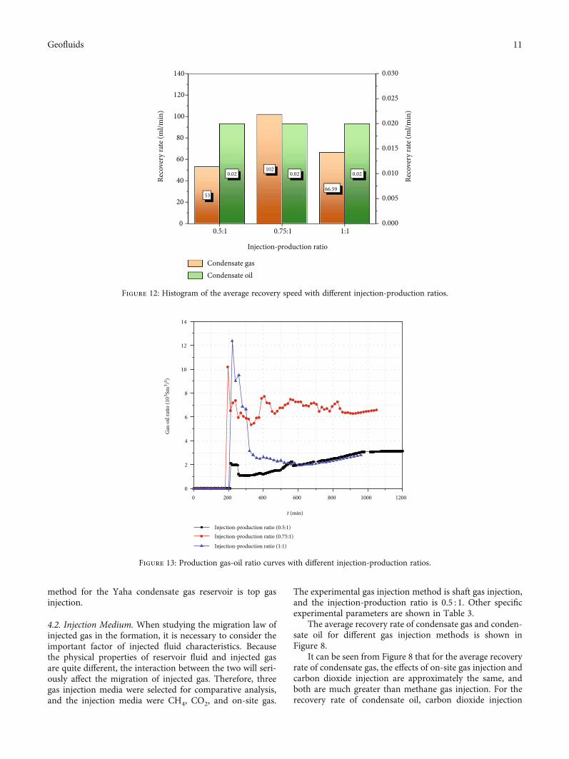
Figure 12: Histogram of the average recovery speed with different injection-production ratios.
0 200 400 600 800 1000 12000
2
4
6
8
10
12
14
Gas
-oil
ratio
(103 Sm
3 /3 )
t (min)
Injection-production ratio (0.5:1)Injection-production ratio (0.75:1)
Injection-production ratio (1:1)
Figure 13: Production gas-oil ratio curves with different injection-production ratios.
11Geofluids

has the best effect with a value of 0.03, followed by on-sitegas injection with a value of 0.02, and finally methane injec-tion with a value of 0.017. Therefore, in order to improve therecovery of condensate gas and condensate oil, carbon diox-ide injection is the best injection medium.
The production gas-oil ratio curves of different gas injec-tion media are shown in Figure 9.
It can be seen from Figure 9 that the changing trends ofthe produced gas-oil ratio curves of different gas injectionmedia are approximately the same, and they all show a trendof first rising rapidly and then falling and finally tending tostabilize. However, the production gas-oil ratio curve of car-bon dioxide injection increased the most in the early stage,the maximum value was close to 8 × 10³ Sm3·m-3, and finally
stabilized near 3:7 × 10³ Sm3·m-3. This is because it isaffected by phase changes in the early stage of production,and even if condensate is precipitated in the later stage ofproduction, the precipitated condensate is mixed with car-bon dioxide, and the condensate is displaced by the mixedphase of carbon dioxide. On the whole, the average produc-tion gas-oil ratio of on-site gas injection is the largest,followed by carbon dioxide injection, and finally methaneinjection.
The cumulative production curves of condensate gas andcondensate oil for different gas injection media are shown inFigure 10.
It can be seen from Figure 10(a) that under the sameproduction pressure, the cumulative gas production curvesof the three different gas injection methods are quite differ-ent, but they all show a trend of gradually increasing andthen becoming stable. In the early stage of gas production(t < 500min), the gas production rate of on-site gas injectionfirst increases and then decreases, while the gas productionrate of carbon dioxide injection first decreases and thenincreases. And the cumulative gas production of on-sitegas injection is greater than the cumulative gas productionof carbon dioxide injection, and the gas production rateand cumulative gas production of methane gas injectionare the smallest. In the middle stage of gas production(t = 500~800min), the gas production rate and cumulativegas production of carbon dioxide injection increase rapidly,which is much greater than the situation of on-site gas injec-tion and methane gas injection. In the later stage of gas pro-duction (t > 800min), the gas production rate of carbondioxide injection is still further increasing, so the cumulativegas production is also gradually increasing. However, theproduction of on-site gas and methane gas was graduallystopped. The cumulative production of on-site gas wasfinally stabilized at about 80 × 103ml, and the cumulative
0 200 400 600 800 1000 12000
20
40
60
80
100
120Cu
mul
ativ
e gas
pro
duct
ion
(103 m
l)
t (min)
Injection-production ratio (0.5:1)
Injection-production ratio (0.75:1)
Injection-production ratio (1:1)
(a) Cumulative gas production curve
Injection-production ratio (0.5:1)
Injection-production ratio (0.75:1)
Injection-production ratio (1:1)
0 200 400 600 800 1000 12000
5
10
15
20
25
Cum
ulat
ive o
il pr
oduc
tion
(ml)
t (min)
(b) Cumulative oil production curve
Figure 14: Cumulative production curve of different injection-production ratios.
0.5:1 0.75:1 1:10%
20%
40%
60%
80%
100%
Injection-production ratio
83.31%
10.76%
59.39%63.19%
71.71%
Ulti
mat
e rec
over
y (%
)
Condensate gas
Condensate oil
80.05%
Figure 15: Histogram of the final recovery factor with differentinjection-production ratios.
12 Geofluids

production of methane gas was finally stabilized at about60 × 103ml.
It can be seen from Figure 10(b) that under the sameproduction pressure, the cumulative oil production curvesof the three different gas injection methods are quite differ-ent, but they all show a trend of increasing first and thenbecoming stable. In the early stage of oil production(t < 400min), the oil production rate and cumulative pro-duction of on-site gas injection are greater than those of car-bon dioxide and methane injection. In the middle stage(t = 400~800min), the oil production rate and cumulativeproduction of carbon dioxide injection gradually increaseand eventually exceed the gas production rate and cumula-tive oil production of on-site gas injection. In the later stage(t > 800min), the output of carbon dioxide injection gradu-ally reaches its maximum value, which is about 27.5ml. Thesecond is the cumulative oil production of on-site gas injec-tion, while methane gas injection ends the oil productionprocess earliest and the cumulative oil production is the low-est. Therefore, through the abovementioned comparativeanalysis, it can be known that among the three gas injectionmethods, carbon dioxide injection is most conducive toimproving the recovery of condensate oil in the Yaha con-densate gas reservoir, followed by on-site gas injection, andfinally methane gas injection.
The final recovery factor histogram of different gas injec-tion methods is shown in Figure 11.
It can be seen from Figure 11 that the final recovery effi-ciency of condensate gas and condensate oil under differentgas injection medium conditions is more obvious. Amongthem, the production effect of carbon dioxide injection isthe best. The final recoveries of condensate gas and conden-sate oil under this condition are both higher than 90%, withvalues of 95.11% and 96.5%, respectively. The final recoveryefficiencies of methane injection and on-site gas injection areapproximately the same. Therefore, in order to furtherimprove the ultimate recovery of condensate gas and con-densate oil, the most suitable gas injection medium shouldbe selected.
4.3. Injection-Production Ratio. The injection volume of gasinjection wells and production wells of condensate gas reser-voirs directly affect the changes in gas layer pressure gradi-ent, and pressure changes have a great impact on gasreservoir recovery. Therefore, a reasonable injection-production ratio is a key factor to ensure oil and gas recov-ery. In order to analyze the influence of injection-production ratio on the Yaha condensate gas reservoir, threephysical simulation experiments of injection-productionratio were selected, which were 0.5 : 1, 0.75 : 1, and 1.1. Theexperimental gas injection medium is methane, and the gasinjection method is shaft gas injection. Other specific exper-imental parameters are shown in Table 3.
The average recovery rate of condensate gas and conden-sate oil for different gas injection-production ratios is shownin Figure 12.
It can be seen from Figure 12 that for the average recov-ery rate of condensate gas, when the injection ratio is 0.75 : 1,the average recovery rate is the largest, with a value of
102ml·min-1. The second is the injection ratio of 0.5 : 1,and the last is the injection ratio of 1 : 1. For the recovery rateof condensate oil, the average recovery rate of the threeinjection-production ratios is the same, which is 0.02.
The production gas-oil ratio curves of different gasinjection-production ratios are shown in Figure 13.
It can be seen from Figure 13 that the changing trends ofthe produced gas-oil ratio curves of different gas injectionmedia are approximately the same. The curves all show arapid rise first, then fall, and finally stabilize. As theinjection-production ratio increases, the production gas-oilratio curve fluctuates more violently in the early productionstage, and the peak value reached is higher. Through com-parative analysis, it can be known that when the injection-production ratio is 1 : 1, the maximum gasoline productionratio is about 12:5 × 10³ Sm3·m-3. In the later stages ofproduction, the production gas-oil ratio curve with aninjection-production ratio of 0.75 : 1 is significantly higherthan the other two cases. The production gas-oil ratiocurves with injection-production ratios of 0.5 : 1 and 1 : 1are approximately coincident and are stable around 3:1 ×10³ Sm3·m-3. Therefore, it can be seen that the productioneffect of the injection-production ratio of 0.5 : 1 and 1 : 1 isbetter than that of the injection-production ratio of0.75 : 1.
The cumulative production curves of condensate gas andcondensate oil with different gas injection ratios are shownin Figure 14.
It can be seen from Figure 14(a) that under the sameproduction pressure, the cumulative gas production curvesof the three different gas injection methods are quite differ-ent, but they all show an increasing trend. With the gradualextension of the production time, the gas production ratewith an injection-production ratio of 0.75 : 1 is the fastestand the cumulative gas production always remains the larg-est, followed by the injection-production ratio 1 : 1. The gasproduction rate and cumulative gas production with aninjection-production ratio of 0.5 : 1 is the lowest. Therefore,through comparative analysis, it can be known that the gasproduction effect with an injection-production ratio of0.75 : 1 is the best.
It can be seen from Figure 14(b) that under the sameproduction pressure, the cumulative oil production curvesof the three different gas injection methods are quite differ-ent, but they all show a trend of increasing first and thenbecoming stable. In the early stage of oil production(t < 300min), the oil production rate and cumulative oil pro-duction with an injection-production ratio of 0.5 : 1 aregreater than those of the other two groups. Moreover, theoil production rate and cumulative oil production with aninjection-production ratio of 0.75 : 1 are greater than the casewhere the injection-production ratio is 1 : 1. In the middleand late stages (t = 400~800min), the oil production rateand cumulative oil production of 1 : 1 injection-productionratio gradually increase, and the final oil production stabi-lizes at around 23.3ml. The cumulative oil production underthis condition surpasses the other two injection-productionratios, which means that the condensate recovery effect isthe best under this condition.
13Geofluids

The final recovery factor histogram of different gas injec-tion methods is shown in Figure 15.
It can be seen from Figure 15 that as the injection-production ratio increases, the condensate gas recovery fac-tor gradually decreases, while the condensate oil recoveryfactor gradually increases. When the injection-productionratio is 0.5 : 1, the recovery factor of condensate gas reachesits maximum value, which is 80.05%. When the injection-production ratio is 1 : 1, the condensate recovery rate reachesthe maximum value, which is 83.31%. Therefore, throughcomparative analysis, it can be known that the increase ofinjection-production ratio is beneficial to the improvementof condensate oil recovery.
5. Summary and Conclusions
(1) Different gas injection methods have different effectson improving the recovery of condensate oil. The topgas injection has a high oil production rate and a lowgas-oil ratio. When the production pressure isreduced from 58MPa to 39MPa, oil is produced rap-idly and the cumulative oil production is the largest.Therefore, under the same production conditions, topgas injection is the best choice, followed by shaft gasinjection, and bottom gas injection has the worst effect
(2) The conclusions obtained from the comparativeanalysis of gas injection media are basically consis-tent with those obtained by previous scholars. Whenthe pressure drops below the dew point pressure, theoutput of condensate increases sharply, the produc-tion effect of carbon dioxide injection is the best,and the condensate recovery rate reaches the maxi-mum with a value of 96.5%
(3) The higher of the injection-production ratio, themore stable the production and recovery rate of con-densate oil and gas. The injection-production ratioand the recovery factor of condensate gas change ininverse proportion, and it is in direct proportion tothe recovery factor of condensate oil. When theinjection-production ratio is 1 : 1, the condensaterecovery rate reaches the maximum value of 83.31%
(4) The research in this paper is based on the Yaha con-densate gas reservoir. Therefore, the conclusionsobtained in this research can provide certain refer-ence value and guiding significance for the injectionparameters of similar gas reservoirs
Data Availability
The (data type) data used to support the findings of thisstudy are available from the corresponding author uponrequest.
Additional Points
Highlights. (1) The Yaha gas condensate reservoir willappear reversed condensate in the later stage of exploitation.
(2) Indoor physical model research helps to understand themechanism of gas migration. (3) Optimizing the condensategas injection scheme helps to improve the recovery efficiencyin the later stages of development.
Conflicts of Interest
The authors declare that they have no conflicts of interest.
Acknowledgments
This study was supported by the China Petroleum MajorScience and Technology Project (Phase III) (No. 2018E-1804.
References
[1] Z. Su, Y. Tang, H. J. Ruan, Y. Wang, and X. Wei, “Experimen-tal and modeling study of CO2 - Improved gas recovery in gascondensate reservoir,” Journal of Petroleum, vol. 3, no. 1,pp. 87–95, 2017.
[2] Z. Xie, H. Y. Deng, andW. Lei, “Study on phase characteristicsof condensate gas reservoir with oil ring,” Drilling & Produc-tion Technology, vol. 32, no. 2, 2009.
[3] P. Guo and Z. C. Li, “Study on the phase behavior of formationfluid in Nanyishan-E3 condensate gas reservoir,” Natural GasIndustry, vol. 19, no. 5, pp. 43–46, 1999.
[4] L. X. Zhou and X. B. Chu, “Study on the phase behavior ofFengshen-1 condensate gas reservoir,” Journal of SouthwestPetroleum University, vol. 30, no. 3, pp. 81–84, 2008.
[5] H. J. Lu, Study on the Distribution of Favorable SedimentaryFacies Belts in the Upper Paleozoic in Block Zhao 51 of SuligeGas Field, Northwest University, Xi'an, 2014.
[6] R. Q. Ming, H. Q. He, and Q. F. Hu, “A new method for pre-diction of water breakthrough time in bottom water conden-sate gas reservoir,” Special Oil and Gas Reservoirs, vol. 25,no. 5, pp. 99–103, 2018.
[7] R. Q. Ming, H. Q. He, and Q. F. Hu, “A newmodel for predict-ing water breakthrough time of high-yield wells in edge watercondensate gas reservoirs,” Special Oil and Gas Reservoirs,vol. 25, no. 2, pp. 76–79, 2018.
[8] Y. Tang, Z. M. Du, Z. L. Qi, S. L. Li, and L. Sun, “Current statusand future development of the study on removal of near-well-bore damage in low-permeability gas condensate wells,” Natu-ral Gas Industry, vol. 27, no. 6, pp. 88–92, 2007.
[9] J. J. Sheng, “Increase liquid oil production by huff-n-puff ofproduced gas in shale gas condensate reservoirs,” Journal ofUnconventional Oil and Gas Resources, vol. 11, pp. 19–26,2015.
[10] S. L. Li, Y. Pan, and L. Sun, “New ideas for improving therecovery efficiency of condensate gas reservoirs,” Natural GasIndustry, vol. 28, no. 9, 2008.
[11] H. Lu, G. Ma, L. Cao, and M. Azimi, “Optimization of lighthydrocarbon recovery system in condensate gas field,” EnergyReports, vol. 5, pp. 1209–1221, 2019.
[12] M. Wang, S. Chen, and M. Lin, “Enhancing recovery and sen-sitivity studies in an unconventional tight gas condensate res-ervoir,” Petroleum Science, vol. 15, no. 2, pp. 305–318, 2018.
[13] L. Jingsong, L. Xiangfang, K. Xiaodong, T. Min, and Z. Yongyi,“New method of cyclic gas injection for condensate gas reser-voirs,” Natural Gas Industry, vol. 24, pp. 76–79, 2004.
14 Geofluids

[14] P. C. Dong, T. W. Jiang, M. L. Tang, and W. Xie, “Optimiza-tion of Yaha-5 condensate gas reservoir developmentmethod,” Daqing Petroleum Geology and Development,vol. 26, no. 3, pp. 51–54, 2007.
[15] F. Lu, Gas injection enhanced oil recovery phase behavior andseepage mechanism of Dalaoba condensate gas reservoir, Jour-nal of Southwest Petroleum University, Chengdu, 2019.
[16] C. W. Lu, “Optimize gas injection to improve the recovery rateof condensate gas field,” Petrochemical Technology, vol. 23,no. 1, 2016.
[17] Y. L. Hu, B. Z. Li, and Z. D. Sun, “Selection of mining methodsfor condensate gas reservoirs,” Natural Gas Geoscience, vol. 14,no. 5, pp. 398–401, 2003.
[18] J. Liu, Fine description of gas reservoirs in Wenjisang Gas Field,Northwest University, Xi’an, 2007.
[19] J. P. Shao and B. R. Niu, “Low-permeability condensate gasreservoir development technology,” China Petroleum and Pet-rochemical, vol. 1, no. 1, pp. 62-63, 2007.
[20] C. F. Hu, K. Zheng, and X. P. Hu, “Application of reservoirnumerical simulation technology in the development of con-densate gas reservoirs with oil rings,” Petroleum Geology andEngineering, vol. 24, no. 3, pp. 46–49, 2010.
[21] A. He, C. Zou, Y. Cui, J. Yan, H. Zhang, and Y. Tang,“Research on increasing the production of condensate withCO2 huff and puff in South A condensate gas reservoir ofZanarol Oilfield,” Reservoir Evaluation and Development,vol. 10, no. 3, 2020.
[22] A. Hassan, M. Abdalla, M. Mahmoud, G. Glatz, A. al-Majed,and A. al-Nakhli, “Condensate-banking removal and gas-production enhancement using thermochemical injection: afield-scale simulation,” Processes, vol. 8, no. 6, p. 727, 2020.
[23] T. Wan and Z. J. Mu, “The use of numerical simulation toinvestigate the enhanced Eagle Ford shale gas condensate wellrecovery using cyclic CO2 injection method with nano-poreeffect,” Fuel, vol. 233, pp. 123–132, 2018.
[24] J. Jiang and R. M. Younis, “Compositional modeling ofenhanced hydrocarbons recovery for fractured shale gas-condensate reservoirs with the effects of capillary pressureand multicomponent mechanisms,” Journal of Natural GasScience and Engineering, vol. 34, pp. 1262–1275, 2016.
[25] Q. H. Feng, B. B. Deng, Y. Z. Yang, J. C. Zhang, X. H. Peng, andJ. K. Yuan, “Reasonable and efficient gas injection develop-ment method for tight sandstone condensate gas reservoirsin Ordos Basin,” Daqing Petroleum Geology and Development,vol. 39, no. 6, pp. 55–62, 2020.
[26] G. H. Yuan, R. J. Wang, S. G. Luo, L. Shang, and X. Z. Wang,“Laboratory test study on enhanced oil recovery by methaneinjection in highly saturated condensate gas reservoirs,” InnerMongolia Petrochemical Industry, vol. 34, no. 11, pp. 21-22,2008.
[27] D. L. Hou, Study on the mechanism and storage of CO2enhanced oil recovery in near-critical condensate gas reservoirs,Southwest Petroleum University, Chengdu, 2014.
[28] S. L. Sui, P. Guo, J. F. Du, and L. X. Xiao, “The experiment ofgas condensate depletion in low-permeability porousmedium,” Journal of Southwest Petroleum University., vol. 32,no. 3, pp. 97–100, 2010.
15Geofluids