EXPERIMENTAL STUDY OF ALTERNATIVE FUEL …umpir.ump.edu.my/id/eprint/8627/1/CD8038_@_43.pdf ·...
24
EXPERIMENTAL STUDY OF ALTERNATIVE FUEL PERFORMANCE OPERATING IN SINGLE CYLINDER DIESEL ENGINE KHALIFATURRAHIM BIN AB RAHMAN Report submitted in partial fulfillment of the requirements for the award of the degree of Bachelor of Mechanical Engineering with Automotive Engineering Faculty of Mechanical Engineering UNIVERSITI MALAYSIA PAHANG JUNE 2013
Transcript of EXPERIMENTAL STUDY OF ALTERNATIVE FUEL …umpir.ump.edu.my/id/eprint/8627/1/CD8038_@_43.pdf ·...

EXPERIMENTAL STUDY OF ALTERNATIVE FUEL PERFORMANCE
OPERATING IN SINGLE CYLINDER DIESEL ENGINE
KHALIFATURRAHIM BIN AB RAHMAN
Report submitted in partial fulfillment of the requirements
for the award of the degree of
Bachelor of Mechanical Engineering with Automotive Engineering
Faculty of Mechanical Engineering
UNIVERSITI MALAYSIA PAHANG
JUNE 2013

vi
ABSTRACT
This report deals with the performance of waste plastic fuel acting on single
cylinder YANMAR diesel engine. The objectives of this project are to analyze the
performance of single cylinder YANMAR diesel engine in context of torque and power
produced by using waste plastic fuel and compared it with the result obtain by using
standard diesel fuel. Second objective is to analyze the consumption of waste plastic
fuel compared to the result obtains by using standard diesel fuel available in market
nowadays. The project used diesel engine with no load which means there is no force
exerted on it. Details studies and research has been done to get knowledge on apparatus
and set up for the project.

vii
ABSTRAK
Laporan ini berkenaan dengan prestasi yang terhasil daripada penggunaan
minyak diesel yang di perbuat daripada plastik terbuang ke atas enjin diesel YANMAR
satu silinder. Objektif projek ini adalah untuk menilai ciri-ciri prestasi yang terhasil
daripada penggunaan bahan plastik terbuang di dalam enjin diesel YANMAR satu
silinder dalam konteks kuasa terhasil dan dibandingkan dengan penggunaan minyak
diesel biasa. Laporan ini juga berkenaan analisis tentang kadar penggunaan minyak
daripada plastik terbuang berbanding minyak diesel yang sedia ada di dalam proses
pembakaran enjin diesel YANMAR satu silinder. Projek ini menggunakan enjin diesel
tanpa beban yang membawa maksud tiada daya atau bebanan yang bertindak keatas
enjin semasa kajian dijalankan. Kajian dan telaah yang secukupnya telah dilakukan
dalam usaha menjayakan projek ini.

viii
TABLE OF CONTENTS
PAGE
SUPERVISOR`S DECLARATION ii
STUDENT`S DECLARATION iii
DEDICATION iv
ACKNOWLEDGEMENT v
ABSTRACT vi
ABSTRAK vii
TABLE OF CONTENTS viii
LIST OF TABLES xi
LIST OF FIGURES xii
LIST OF SYMBOLS xiii
LIST OF ABBREVIATIONS xiv
CHAPTER 1 INTRODUCTION
1.1 Introduction 1
1.2 Project Background 1
1.3 Problem Statement 3
1.4 Project Objectives 3
1.5 Scope of Study 4
CHAPTER 2 LITERATURE REVIEW
2.1 Introduction 5
2.2 Diesel Engine 5
2.2.1 History 6
2.2.2 Fundamental of Diesel Engine

ix
2.2.2.1 Four-Stroke Diesel Engine Cycle 7
2.2.2.2 Two-Stroke Diesel Engine Cycle 10
2.3 Characteristic of Diesel Fuel 11
2.4 Waste Plastic Disposal Fuel 14
2.4.1 Suitable Plastics 15
2.4.2 Typical Process 17
CHAPTER 3 METHODOLOGY
3.1 Introduction 19
3.2 Experiment Procedure
3.2.1 Fuel Consumption Analysis 20
3.2.2 Performance Analysis 20
3.3 Flow Chart 21
3.3.1 Flow Chart Description 22
3.4 Project Supervisor 23
3.5 Tools 23
3.6 Apparatus
3.6.1 YANMAR Engine 24
3.6.2 Hydraulic Compressor 24
3.6.3 Exhaust Gas Temperature Sensor 25
3.6.4 Engine Speed Sensor 25
3.6.5 Fuel Flow Meter 26
3.7 Apparatus Setup 27
CHAPTER 4 RESULT AND DISCUSSION
4.1 Introduction 28
4.2 Performance of Engine
4.2.1 Torque 29
4.2.2 Power Output 31
4.3 Fuel Consumption 34

x
CHAPTER 5 CONCLUSION AND RECOMMENDATION
5.1 Conclusion 37
5.2 Recommendation for Future Research 38
REFERENCES 39
APPENDICES
A1 Gantt Chart/Project Schedule ForFyp 1 41
A2 Gantt Chart/Project Schedule ForFyp 2 42
A3 Single Cylinder Diesel Engine Yanmar-Tf120m Specification 43

xi
LIST OF TABLES
Table Title Page
1.1 Municipal Solid Waste Composition from
Kuala Lumpur 2
2.1 Diesel and waste plastic fuel specification for
selected requirement 13
2.2 Calorific values of plastics compared with conventional
fuels 15
2.3 Comparison of Waste Plastics Fuel to Regular Gasoline 16
4.1 Engine torque data obtain from the experiment 29
4.2 Engine power data obtain from the experiment 31
4.3 Fuel consumption data obtain from the experiment 34

xii
LIST OF FIGURES
Figure Title Page
2.1 Four-Stroke Diesel Engine Cycle 8
2.2 Two-Stroke Diesel Engine Cycle 10
3.1 YANMAR TF 120 Single Cylinder Diesel Engines 24
3.2 Hydraulic Compressor 24
3.3 Multipoint Temperature Indicator 25
3.4 Flow Meter Indicator 26
3.5 Schematic Diagram of the Experiment 27
4.1 Torque VS Engine Speed 30
4.2 Power VS Engine Speed 32
4.3 Fuel Consumption VS Engine Speed 35

xiii
LIST OF SYMBOLS
l/h Litre per Hour
P Power
kW kiloWatt
T Torque
N Engine Speed

xiv
LIST OF ABBREVIATIONS
CC Cubic Centimeters
BHP Brake Horse Power
WPD Waste Plastic Disposal
NOx Nitrogen Oxides
PM Particulate Matter
BTDC Before Top Dead Center
TDC Top Dead Center
Nil Not Detected

1
CHAPTER 1
INTRODUCTION
1.1 INTRODUCTION
Management systems and techniques have been developed to reduce the
environmental burden of waste production and at the same time to address possibilities
of the conversion of waste to energy. Disposal of organic waste in landfills produces
methane, which should be minimized via capture and subsequently used as a fuel for
reducing greenhouse gas emissions. In addition, the by-products of incineration usually
contain some toxic contaminants. However waste treatment still this can provide option
needs a viable to be possibility analyzed for with energy specific production, tools its
environmental impact. This chapter discussed about the project background, problem
statement, objectives and the scope of this experimental study. This chapter shows the
main and starting points for the progress of this study. The study will described and
focused toward the performance of single cylinder diesel engine fueled by waste plastics
fuel and the fuel consumption of both fuel.
1.2 PROJECT BACKGROUND
A fast-growing economic in emerging-developing countries, typically at the
capital city, has encouraged an increased solid waste generation in that specific area.
With the development inMalaysia country, along with the economic growth and
business activity and consumption rate will accelerate the daily generation and volume
rate of municipal solid waste. Government Board of Kuala Lumpur City has managed
as many as 2.500 tons of municipal solid waste a day for the year 1998 for at least
912.500 tons. Generally, Malaysia generated around 18000 Mtons every day. In current

2
investigations carried out by the Board of Government of Kuala Lumpur has record a
samplefrom solid waste samples collection at certain location around 100 kg weights
per sample, and the composition which could be found from the sample is as Table 1.1.
Table 1.1: Municipal Solid Waste Composition from Kuala Lumpur
Source: ChamhuriSiwar (2010)
This experiment is using single cylinder diesel engine as the main apparatus. It
is a single piston diesel engine with 638cc of displacement. This engine has 12 bhp of
output and 10.5 bhp of continuous output. Its cooling system use water cooled cooling
system with radiator. This engine also uses direct fuel injection with a high pressure
pump. The basic characteristics of this engine are it is a four stroke, compression-
ignition engine which the fuel and air are mixed inside the engine. The air required for
combustion is highly compressed inside the combustion chamber. It will generate high
temperatures which are sufficient for the diesel fuel to spontaneously ignite when it is
injected to the cylinder.
The diesel engine thus uses heat to release the chemical energy contained within
the diesel fuel and convert it into mechanical forces. The specification of the engine can
be seen clearly from Appendix 3. In this experiment, the condition used is zero loads
which mean there is no load exerted on the engine.
Type of Solid Waste Percentage of Total Solid Waste
Sample
Food waste 74 percent
Plastics 21 percent
Paper 1 percent
Mixed Organic 1 percent
Wood 1 percent
Others 2 percent

3
1.3 PROBLEM STATEMENT
Millions of tons of waste plastics are generated every year worldwide.
Municipal and commercial solid wastes contain a large amount of plastics and most of
these plastics are not biodegradable. Hence the disposal of waste plastics has been an
important concern for the society. The most common method is to use a landfill.
Incineration, on the other hand, burns the plastics, but it can cause air pollution.
Therefore, energy recovery from waste plastics is gaining importance because of its
potential to eliminate plastics and at the same time generate energy using free feedstock,
that is, waste plastics.
There are applications such as large marine vessels where fuel is scarce and
expensive, and at the same time the waste plastics generated onboard are available at a
negative cost. In a carbon-constrained world, the using of diesel fuel has contributed too
much carbon pollution in world. Biodiesel is an alternate fuel that has lower net carbon
emissions than fossil fuels.
1.4 PROJECT OBJECTIVES
The objectives of this project are to analyze the performance of single cylinder
diesel engine by using waste plastic fuel and to analyze the consumption of waste
plastic fuel compared to the result obtain by using standard diesel fuel available in
market nowadays.

4
1.5 SCOPE OF STUDY
The following scopes of the project are determined to achieve the objectives of
the project.
i. Analyzing the fuel consumption by using both fuel which are waste
plastic fuel and standard diesel fuel in single cylinder diesel engine
ii. Analyzing the engine performance by using both fuel which are waste
plastic fuel and standard diesel fuel in single cylinder diesel engine

5
CHAPTER 2
LITERATURE REVIEW
2.1 INTRODUCTION
The purpose of this chapter is to review the information which related to this
project such Internal Combustion Engine characteristics, characteristic of waste plastic
disposal (WPD) fuel and diesel fuel, and the basic fundamental of diesel engine cycle.
2.2 DIESEL ENGINE
Almost all gasoline, spark-ignited engines run at stoichiometric conditions,
which are the point where available oxygen from the air is completely consumed,
oxidizing the fuel delivered to the engine. Stoichiometric spark-ignited engines use a
homogenous air-fuel mixture with early fuel introduction for good fuel vaporization.
Gasoline fuel delivery systemshave evolved from carbureted systems to throttle body
injection, multipoint fuel injection and sequential. The latest evolutionary step,
stoichiometric direct injection, represents a significant improvement for spark-ignited
engines and when combined with turbocharging and engine downsizing makes them
competitive with diesel engines in terms of fuel economyand performance.
Unlike gasoline spark-ignited engines, which always control both the amount of
air and the amount of fuel close to complete combustion conditions, the diesel engine
runs throttled with an excess of air (lean operation). Particulate matter (PM) and
nitrogen oxides (NOx) emissions are more challenging to control and are the main focus
of diesel emissions control research, as well as the main source of technology costs.
6
Engine-out particulate matters emissions are also much higher than on spark-
ignited engines due to direct in-cylinder fuel injection. The timing of fuel combustion is
controlled when fuel is injected and the fuel ignites almost immediately after injection.
This allows little time for the fuel to vaporize and mix with air, creating flame plumes.
During this combustion process, carbonaceous particulates grow by aggregating with
other organic and inorganic particles. Thus, particulate matter (both mass and number)
is also much more challenging to control in a diesel engine, Francisco Posada (2012).
Diesels are workhorse engines. That is why diesel is used powering heavy duty
trucks, buses, tractors, and trains, not to mention large ships, bulldozers, cranes, and
other construction equipment.In the past, diesels fit the stereotype of muscle-bound
behemoths. They were dirty and sluggish, smelly and loud. That image does not apply
to today’s diesel engines. However and tomorrow’s diesels will show even greater
improvements. They will be even more fuel efficient, more flexible in the fuels they can
use, and also much cleaner in emissions.
2.2.1 History
German engineer Rudolph Diesel patented the diesel engine in 1892. He first
considered powdered coal as a possible fuel, but it proved difficult to inject into the
cylinder and caused an explosion that destroyed the prototype engine. He later
experimented with vegetable oils and successfully used peanut oil. Ultimately, Diesel
settled on a stable byproduct of the petroleum refinement process that would come to be
known as "diesel fuel."
In this engine, air was drawn into the cylinder and was compressed to 35-40
bar. Towards the end of the compression stroke, an air blast was introduced into the
combustion space at a much higher pressure, about 68-70 bar, thus causing turbulence
in the combustion chamber. A three-stage compressor driven by the engine (and
consuming about 15% of the engine's gross power) supplied compressed air which was
stored in a reservoir. This compressed air served both for starting the engine and for air-
injection into the compressed air already in the cylinder - that is, for blasting air to
atomize the oil fuel by forcing it through perforated discs fitted around a fluted needle-
7
valve injector. The resulting finely divided oil mist ignites at once when it contacts the
hot compressed cylinder air, and the burning rate then tends to match the increasing
cylinder volume as the piston moves outwards-expansion will therefore take place at
something approaching constant pressure.
2.2.2 Fundamental of Diesel Engine
A diesel is aninternal combustion engine thatconverts chemical energy in fuel
to mechanical energy that moves pistons up and down inside enclosed spaces called
cylinders. The pistons are connected to the engine’s crankshaft, which changes their
linear motion into the rotary motion needed to propel the vehicle’s wheels. To convert
the chemical energy of the fuel into useful mechanical energy all internal combustion
engines must go through four events: intake, compression, power, and exhaust. How
these events are timed and how they occur differentiates the various types of engines.
All diesel engines fall into one of two categories, two-stroke or four-stroke cycle
engines. The word cycle refers to any operation or series of events that repeats itself, R.
Diesel (1895).
2.2.2.1 Four-Stroke Diesel Engine Cycle
In a four-stroke engine the camshaft is geared so that it rotates at half the speed
of the crankshaft (1:2). This means that the crankshaft must make two complete
revolutions before the camshaft will complete one revolution. The following section
will describe a four-stroke, normally aspirated, diesel engine having both intake and
exhaust valves with a 3.5-inch bore and 4-inch stroke with a 16:1 compression ratio, as
it passes through one complete cycle.

8
Figure 2.1: Four-Stroke Diesel Engine Cycle
Source: Gilbert (DOE)
Intake / Induction
As the piston moves upward and approaches before top dead center (BTDC), the
camshaft lobe starts to lift the cam follower. This causes the pushrod to move upward
and pivots the rocker arm on the rocker arm shaft. As the valve lash is taken up, the
rocker arm pushes the intake valve downward and the valve starts to open. The intake
stroke now starts while the exhaust valve is still open. The flows of the exhaust gasses
will have created a lowpressure condition within the cylinder and will help pull in the
fresh air charge.The piston continues its upward travel through top dead center (TDC)
while fresh air enters and exhaust gasses leave. At about after top dead center (ATDC),
the camshaft exhaust lobe rotates so that the exhaust valve will start to close. The valve
is fully closed at ATDC. This is accomplished through the valve spring, which
wascompressed when the valve was opened, forcing the rocker arm and cam follower
back against the cam lobe as it rotates. The time frame during which both the intake and
exhaust valves are open is called valve overlap and is necessary to allow the fresh air to
help scavenge (remove) the spent exhaust gasses and cool the cylinder. In most engines,
30 to 50 times cylindervolume is scavenged through the cylinder during overlap. This
excess cool air also provides the necessary cooling effect on the engine parts. As the
piston passes TDC and begins to travel down the cylinder bore, the movement of the
piston creates suction and continues to draw fresh air into the cylinder.

9
Compression
With both the inlet and the exhaust valves closed, the piston moves towards the
cylinder head. The air enclosed in the cylinder will be compressed into a much smaller
space of anything from 1/12 to 1/24 of its original volume. A typical ratio of maximum
to minimum air-charge volume in the cylinder would be 16:1, but this largely depends
on engine size and designed speed range.During the compression stroke, the air charge
initially at atmospheric pressure and temperature is reduced in volume until the cylinder
pressure is raised to between 30 and 50 bar. This compression of the air generates heat
which will increase the charge temperature to at least 600°C under normal running
conditions.
Power
Both valves are closed, and the fresh air charge has been compressed. The fuel
has been injected and is starting to burn. After the piston passes TDC, heat is rapidly
released by the ignition of the fuel,causing a rise in cylinder pressure.
Combustiontemperatures are around 2336°F. This rise in pressure forces the piston
downward and increases the force on the crankshaft for the power stroke.
Exhaust
When the burning of the charge is near completion and the piston has reached
the outermost position, the exhaust valve is opened. The piston then reverses its
direction of motion and moves towards the cylinder head. The sudden opening of the
exhaust valve towards the end of the power stroke will release the still burning products
of combustion to the atmosphere. The pressure energy of the gases at this point will
accelerate their
expulsion from the cylinder, and only towards the end of the piston's return stroke will
the piston actually catch up with the tail-end of the outgoing gases.

10
2.2.2.2 Two-Stroke Diesel Engine Cycle
The pump scavenge two stroke diesel engine designed by Sir Dugald Clerk in
1879 was the first successful two-stroke engine; thus the two-stroke-cycle engine is
sometimes called the Clerk engine.
Figure 2.2: Two-Stroke Diesel Engine Cycle
Source: Gilbert (DOE
Exhaust and Intake
At ATDC, with the piston near the end of its power stroke, the exhaust cam
begins to lift the exhaust valves follower. The valve lash is taken up; the rocker arm
forces the exhaust valve off its seat. The exhaust gasses start to escape into the exhaust
manifold, as shown in Figure2.2. Cylinder pressure starts to decrease. After the piston
travels three-quarters of its (down) stroke of crankshaft rotation, the piston starts to
uncover the inlet ports. As the exhaust valve is still open, the uncovering of the inlet
ports lets the compressed fresh air enter the cylinder and helps cool the cylinder and
scavenge the cylinder of the remaining exhaust gasses.At ABDC, the camshaft starts to
close the exhaust valve. The camshaft has rotated sufficiently to allow the spring
pressure to close the exhaust valve. Also, as the piston travels past ABDC (after the
exhaust valve starts closing), the intake ports are closed off by the piston.

11
Compression
Towards the end of the power stroke, the inlet ports will be uncovered. The
piston then reaches its outermost position and reverses its direction of motion. The
piston now moves upwards so that the piston seals and closes the inlet air ports, and just
a little later the exhaust valves close. Any further upward movement will now compress
the trapped air. Power phase as shown in Figure 2.2(c) shortly before the piston reaches
the innermost position to the cylinder head on its upward compression stroke; highly
pressurized liquid fuel is sprayed into the dense intensely heated air charge. Within a
very short period of time, the injected fuel droplets will vaporize and ignite, and rapid
burning will be established by the time the piston is at the top of its stroke. The heat
liberated from the charge will be converted mainly into gas-pressure energy which will
expand the gas and so do useful work in driving the piston outwards.
2.3 CHARACTERISTIC OF DIESEL FUEL
The components of diesel fuels are straight run fractions containing paraffinic
and naphthenic hydrocarbons, naphtha and cracked gas oils. The atmospheric gas oils
tend to have good ignition quality (cetane number) but many contain some high melting
point hydrocarbons (waxes) that can result in high cloud and high pour points. These
fractions are blended to produce different seasonal grades of diesel fuels required to
meet a wide range of diesel engine uses.
Cetane number is a measure of the ignition delay of a diesel fuel. The shorter
the interval between the time the fuel is injected and the time it begins to burn, the
higher is its cetane number. It is a measure of the ease with which the fuel can be
ignited and is most significant in low temperature starting, warm up, idling and smooth,
even combustion. Cetane number requirements depend on engine design and size,
nature of speed and load variations, and starting and atmosphere conditions.Some
hydrocarbons ignite more readily than others and are desirable because of this short
ignition delay. The preferred hydrocarbons in order of their decreasing cetane number
are normal paraffins, olefins, naphthenes, iso-paraffins and aromatics.Cetane number is
measured in a single cylinder test engine with a variable compression ratio.
12
Low-Temperature Flow: Unlike gasoline, which have freezing points well
below even the most severe winter ambient, diesel fuels have pour points and cloud
points well within the range of temperatures at which they might be used. This can be of
particularconcern when using fuel delivered during the summer season. Seasonal
blending to control cloud point (the temperature at which a cloud or haze of wax
crystals first appears and separates from the fuel) is the refiner’s assurance against field
problems. In the winter, there is also an increasing tendency to use flow improvers, as
well as polymeric additives that modify the wax structure as it builds up during cooling.
These additives keep wax crystals small, so they can pass through the fine pores of fuel
filters, enroute to the injector pump.
Viscosity influences the spray pattern when the fuel is injected into the cylinder.
Low-speedmarine engines can use higher-viscosity fuels than high-speed road-transport
and generator engines, and still run without excessive smoking. Minimum viscosity
limits are imposed to prevent the fuel from causing wear in the fuel injection pump.
Volatility of a diesel fuel has little influence on its engine performance, except
as it affects exhaust smoking tendencies. The distillation range of a diesel fuel does not
allow much flexibility in this regard, because of the interdependence with other
specification factors. Because diesel fuels are classified as nonflammable for freight
purposes, minimum flash point restrictions are imposed.
Fuel lubricity also influences the characteristics of diesel fuel. Some processes
used to desulphurize diesel fuel, if severe enough, can also reduce the natural
lubricating qualities of the diesel fuel. Since engines require the diesel fuel to act as a
lubricant for their injection systems, diesel fuel must have sufficient lubricity to give
adequate protection against excessive injection system wear.
Sulfur content is the first diesel fuel property to be widely controlled by
legislation, aimed at limiting exhaust emissions. Sulfur is present in all crude oils and as
well as all refined products.During combustion, however, sulfur compounds burn to
form acidic byproducts, S02 and S0, which form sulfates in the exhaust gas stream.
13
Sulfates are part of a diesel engine’s particulate emissions. Therefore, controlling
fuelsulfur level reduces the level of sulfate pollutants. Depending on the crude source,
sulfur compounds can also create corrosive sulfur oxides on combustion. These can
cause high rates of engine wear and a rapid depletion of engine oil additives. Engine
manufacturers often relate oil change intervals to the fuel sulfur content.
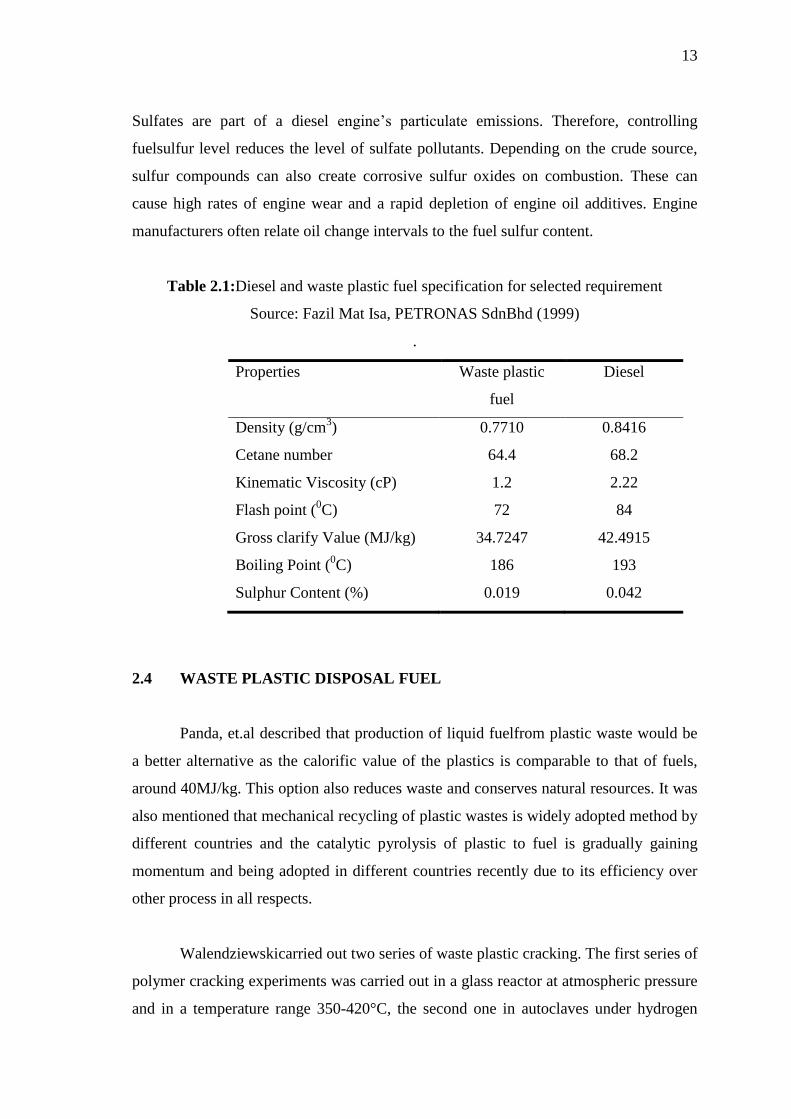
Table 2.1:Diesel and waste plastic fuel specification for selected requirement
Source: Fazil Mat Isa, PETRONAS SdnBhd (1999)
.
Properties Waste plastic
fuel
Diesel
Density (g/cm3) 0.7710 0.8416
Cetane number 64.4 68.2
Kinematic Viscosity (cP) 1.2 2.22
Flash point (0C) 72 84
Gross clarify Value (MJ/kg) 34.7247 42.4915
Boiling Point (0C) 186 193
Sulphur Content (%) 0.019 0.042
2.4 WASTE PLASTIC DISPOSAL FUEL
Panda, et.al described that production of liquid fuelfrom plastic waste would be
a better alternative as the calorific value of the plastics is comparable to that of fuels,
around 40MJ/kg. This option also reduces waste and conserves natural resources. It was
also mentioned that mechanical recycling of plastic wastes is widely adopted method by
different countries and the catalytic pyrolysis of plastic to fuel is gradually gaining
momentum and being adopted in different countries recently due to its efficiency over
other process in all respects.
Walendziewskicarried out two series of waste plastic cracking. The first series of
polymer cracking experiments was carried out in a glass reactor at atmospheric pressure
and in a temperature range 350-420°C, the second one in autoclaves under hydrogen

14
pressure (~3-5MPa) in temperature range 380-440°C. They also concluded that the
application of catalyst results in lowering of polymers cracking temperature, density of
obtained liquid and increased the gas fuel yield.
Channdrasekar Murugesan, et.al described the hydrocracking of polymer waste
typicallyinvolves reaction with hydrogen over a catalyst in a stirred batchautoclave at
moderate temperatures and pressures. The work reported mainlyfocuses on obtaining a
high quality gasoline starting from a wide range of feeds. Typicalfeeds include
polyethylene, polyethylene terephthalate, polystyrene, polyvinyl chloride and mixed
polymers, polymerwaste from municipal solid waste and other sources, co-mixing of
polymers with coal, co-mixing of polymers with different refineryoils such as vacuum
gas–oil and scrap tires alone or co-processedwith coal. To aid mixing and reaction,
solvents such as 1-methylnaphthalene, tetralin and decalin have been used with
somesuccess. Several catalysts, classically used in refinery hydrocracking reactions,
have been evaluated and include transition metals such as Ferus (Fe) supported on acid
solids (such as alumina, amorphous silica–alumina, zeolites and sulphatedzirconia).
Thesecatalysts incorporate both cracking and hydrogenation activitiesand although
gasoline product range streams have been obtained,little information on effect of metal
and catalyst, surface areas, ratio or sensitivity to deactivation is quoted. Table 2.2
shows the comparison between waste plastic fuels with the other conventional fuel in
content of Calorific Value.