
EXPERIMENTAL REVIEW OF THE WELDING METALLURGY OF … · four digit number system. Cast alloy...
11
EXPERIMENTAL REVIEW OF THE WELDING METALLURGY OF HIGH-STRENGTH ALUMINIUM ALLOY 7025-T6 M. OLABODE, P. KAH and J. MARTIKAINEN Lappeenranta University of Technology, Lappeenranta, Finland In this review, various aspects such as designations, definitions, applications, properties and weldability of high-strength aluminium alloys are presented. The effect of heat input on microstructure and hardness of the 7025-T6 alloy welded joints is studied. It is shown that at constant heat input the welding speed had no effect on the weld hardness. Thus, limiting heat input in welds on high-strength aluminium alloys is important to preserve their mechanical properties. Keywords: high-strength aluminium alloys, alloy 7025-T6, pulsed MIG welding, heat input, Vickers hardness, welding metallurgy Light welded metal structures are in high demand, and the market keeps growing along with societal needs. The diversification of aluminium structures also continues to grow. Welding is an important process in producing these structures. The fusion welding of high-strength aluminium alloys (HSA) using pulsed MIG method involves heat input and is, thus, chal- lenging but accomplishable if proper care is taken to understand the nature and behaviour of HSA being welded. A number of studies [1—3] have shown that earlier technologies available for welding HSA present poor weldability due to the presence of copper in the alloy. However, new technologies like pulsed MIG welding, pulsed TIG welding and friction stir welding (FSW) can be effectively to compared with conven- tional fusion methods. FSW proved to be presently the most acceptable process as it allows obtaining important metallurgical advantages, for example, no solidification and liquation cracking, compared with fusion welding [4]. Based on literature review, this paper outlines the definitions, properties, applica- tions, weldability, welding defects of HSA and studies their weldability with a focus on the effect of heat input on welding metallurgy using the pulsed MIG process. This study adopts both a literature review of HSA and an experimental study of 7025-T6 alloy welded by robotised pulsed MIG method. In addition, the effect of heat input and welding speed as welding parameters on welding metallurgy of HSA are pre- sented. It was found that the grains reduce in size as heat input decreases, and welding speed had no effect on the hardness across the weld if heat input was kept constant. The hardness of HSA joints lower in the HAZ than in the parent metal. This study is of sig- nificance as there are limited studies available about the welding metallurgy of the 7025-T6 alloy. Alloy designation. Aluminium alloys are grouped into cast and wrought ones and are identified with a four digit number system. Cast alloy designations are similar to those of wrought alloys but with a decimal between the third and fourth digit (123.0). The second part of the designation is the temper which accounts for the fabrication process. When the second part starts with T, e.g. T6, it means that the alloy was thermally treated. The numbers show the type of the treatment and other consequent mechanical treat- ment, namely T6 shows that the alloy is solution heat- treated and artificially aged [5]. In alloy designations F denotes as fabricated and O – annealed. An addi- tional suffix indicates the specific heat treatment. H denotes strain-hardened (cold-worked) and it is al- ways followed by at least two digits to identify the level of cold-working and other heat treatments that have been carried out to attain the required mechanical properties. W denotes solution heat-treated, it is fol- lowed by a time indicating the natural ageing period, e.g. W 1 h. T denotes thermally treated and is always followed by one or more numbers to identify the spe- cific heat treatment [4]. The full designation therefore has two parts which specify the chemistry and the fabrication history, e.g. in 7025-T6, 7025 specifies the chemistry while T6 – the fabrication. Aluminium is classified based on the chemical composition. The classification is mainly in two categories based on the type of production which are wrought aluminium alloys (fabricated alloys) and cast aluminium alloys. Others can be categorised on the basis of strain hardening possibility or heat treat- ment [6]. The wrought aluminium category is large because aluminium can be formed to shapes by virtu- ally any known process including extruding, drawing, forging, rolling etc. Wrought alloys need to be ductile to aid fabrication, whereas cast aluminium alloys need to be fluid in nature to aid castability [7]. Cast alu- minium alloys are identified with four digits in their classification. A decimal point separates the third and fourth digit. The first digit indicates the alloy group which is based on the major alloying element (Ta- ble 1) [8]. The next two digits denote the aluminium alloy itself or the purity of the alloy. In lxx.x series © M. OLABODE, P. KAH and J. MARTIKAINEN, 2012 20 4/2012
Transcript of EXPERIMENTAL REVIEW OF THE WELDING METALLURGY OF … · four digit number system. Cast alloy...

EXPERIMENTAL REVIEWOF THE WELDING METALLURGY
OF HIGH-STRENGTH ALUMINIUM ALLOY 7025-T6
M. OLABODE, P. KAH and J. MARTIKAINENLappeenranta University of Technology, Lappeenranta, Finland
In this review, various aspects such as designations, definitions, applications, properties and weldability of high-strengthaluminium alloys are presented. The effect of heat input on microstructure and hardness of the 7025-T6 alloy weldedjoints is studied. It is shown that at constant heat input the welding speed had no effect on the weld hardness. Thus,limiting heat input in welds on high-strength aluminium alloys is important to preserve their mechanical properties.
Keywo rd s : high-strength aluminium alloys, alloy 7025-T6,pulsed MIG welding, heat input, Vickers hardness, weldingmetallurgy
Light welded metal structures are in high demand,and the market keeps growing along with societalneeds. The diversification of aluminium structures alsocontinues to grow. Welding is an important processin producing these structures. The fusion welding ofhigh-strength aluminium alloys (HSA) using pulsedMIG method involves heat input and is, thus, chal-lenging but accomplishable if proper care is taken tounderstand the nature and behaviour of HSA beingwelded. A number of studies [1—3] have shown thatearlier technologies available for welding HSA presentpoor weldability due to the presence of copper in thealloy. However, new technologies like pulsed MIGwelding, pulsed TIG welding and friction stir welding(FSW) can be effectively to compared with conven-tional fusion methods. FSW proved to be presentlythe most acceptable process as it allows obtainingimportant metallurgical advantages, for example, nosolidification and liquation cracking, compared withfusion welding [4]. Based on literature review, thispaper outlines the definitions, properties, applica-tions, weldability, welding defects of HSA and studiestheir weldability with a focus on the effect of heatinput on welding metallurgy using the pulsed MIGprocess. This study adopts both a literature review ofHSA and an experimental study of 7025-T6 alloywelded by robotised pulsed MIG method. In addition,the effect of heat input and welding speed as weldingparameters on welding metallurgy of HSA are pre-sented. It was found that the grains reduce in size asheat input decreases, and welding speed had no effecton the hardness across the weld if heat input was keptconstant. The hardness of HSA joints lower in theHAZ than in the parent metal. This study is of sig-nificance as there are limited studies available aboutthe welding metallurgy of the 7025-T6 alloy.
Alloy designation. Aluminium alloys are groupedinto cast and wrought ones and are identified with a
four digit number system. Cast alloy designations aresimilar to those of wrought alloys but with a decimalbetween the third and fourth digit (123.0). The secondpart of the designation is the temper which accountsfor the fabrication process. When the second partstarts with T, e.g. T6, it means that the alloy wasthermally treated. The numbers show the type of thetreatment and other consequent mechanical treat-ment, namely T6 shows that the alloy is solution heat-treated and artificially aged [5]. In alloy designationsF denotes as fabricated and O – annealed. An addi-tional suffix indicates the specific heat treatment. Hdenotes strain-hardened (cold-worked) and it is al-ways followed by at least two digits to identify thelevel of cold-working and other heat treatments thathave been carried out to attain the required mechanicalproperties. W denotes solution heat-treated, it is fol-lowed by a time indicating the natural ageing period,e.g. W 1 h. T denotes thermally treated and is alwaysfollowed by one or more numbers to identify the spe-cific heat treatment [4].
The full designation therefore has two parts whichspecify the chemistry and the fabrication history, e.g.in 7025-T6, 7025 specifies the chemistry while T6 –the fabrication. Aluminium is classified based on thechemical composition. The classification is mainly intwo categories based on the type of production whichare wrought aluminium alloys (fabricated alloys) andcast aluminium alloys. Others can be categorised onthe basis of strain hardening possibility or heat treat-ment [6]. The wrought aluminium category is largebecause aluminium can be formed to shapes by virtu-ally any known process including extruding, drawing,forging, rolling etc. Wrought alloys need to be ductileto aid fabrication, whereas cast aluminium alloys needto be fluid in nature to aid castability [7]. Cast alu-minium alloys are identified with four digits in theirclassification. A decimal point separates the third andfourth digit. The first digit indicates the alloy groupwhich is based on the major alloying element (Ta-ble 1) [8]. The next two digits denote the aluminiumalloy itself or the purity of the alloy. In lxx.x series
© M. OLABODE, P. KAH and J. MARTIKAINEN, 2012
20 4/2012

alloys, these two digits denote the purity in percent-ages. For example, 150.0 show the minimum 99.5 %purity of the aluminium alloy. In the groups 2xx.x—9xx.x series, the two digits signify the different alloyspresent in the group. The last digit signifies how theproduct is formed. For example, 0 denotes casting,and 1 or 2 – ingot based on what chemical compo-sition the ingot has.
Further modifications from the original cast alu-minium alloy groups are identified by adding a serialletter in front of the numerical denotations. The serialletters are assigned in alphabetical order starting withA but omitting I, O, Q and X [8]. X is left out withexperimental alloys.
Wrought alloys are given four digits. The first onerepresents the alloy group which is based on the majoralloying element (Table 2). The second digit tells howthe alloy has been modified or the limits of impurity.0 in the second digit denotes an original alloy. Num-bers 1—9 signify the different alloy modifications withslight variation in their compositions. In the 1xxxseries the second number denotes the modifications inimpurity limits: 0 implies that the alloy has a naturalimpurity limit, 1—9 imply that special control has beencarried out on one or more impurities or alloying ele-ment. The last two numbers represent the purity ofthe alloy [6].
In the 1xxx series the last two numbers signify thealloy level of purity. For example, 1070 or 1170 im-plies that at least 99.7 % Al is present in the alloy,1050 or 1250 – no less than 99.5 % Al, and 1100 or1200 – at least 99.0 % Al. For all the other series ofaluminium alloys (2xxx—8xxx) the last two numbershave no special significance but are used to identifyalloys in the group [6, 8].
High-strength and ultra high-strength aluminiumalloys. Aluminium alloys with at least 300 MPa yieldstrength are regarded to be HSA, whereas ultra high-strength aluminium alloys (UHSA) are those withyield strength of 400 MPa or more. HSA and UHSAare generally included in the 2xxx, 7xxx, and 8xxxseries. There are no strict rules as to what series HSAand UHSA belong to. For example, two alloys canhave significantly different yield strengths within thesame series. To be exact, the HSA and UHSA can beclassified only specifically to certain alloys in the se-ries. For generality purpose, however, an averagerange of the series yield strength is used to identifyHSA and UHSA (see Table 2).
Properties and applications of HSA and UHSASeries. The 2xxx series includes the Al—Cu alloys.The major characteristics of the 2xxx series are heattreatability, high strength both at room and elevatedtemperatures, and high tensile strength range of 68.9—520 MPa [9, 10]. The alloys can be joined mechani-
Table 1. Cast aluminium alloy classification [6—9]
Series Alloying elements Content, % Tensile strength, MPa Series average value, MPa
1хх.х Al Min 99.0
2хх.х Cu 4.0—4.6 145—476 302
3хх.х Si 5—17 159—359 249
With added Cu and/or Mg 5—17 159—359 249
4хх.х Si 5—12 131—296 187
5хх.х Mg 4—10 138—331 232
7хх.х Zi 6.2—7.5 241 241
8хх.х Sn — 138—221 163
9хх.х Others — — —
Table 2. Wrought aluminium alloy classification [6, 8, 9]
Series Alloying elements Content, % Tensile strength, MPa Series average value, MPa
1ххх Al Min 99.0 10.0—165 94.4
2ххх Cu 1.9—6.8 68.9—520 303
3ххх Mn 0.3—1.5 41.4—285 163
4ххх Si 3.6—13.5 70.0—393 275
5ххх Mg 0.5—5.5 40.0—435 194
6ххх Mg and Si 0.4—1.5 40.0—435 241
Si 0.2—1.7 40.0—435 241
7ххх Zn 1.0—8.2 80.0—725 399
8ххх Others — 110—515 365
4/2012 21

cally while some are weldable [11]. The chemical com-position is usually copper and some other possibleelements, like magnesium, manganese and silicon.They comprise high strength products that are usuallytypical of the aviation industry (2024 alloy). In theindustry they are expected to meet high engineeringstandards due to high safety requirements. These re-quirements make the 2xxx series expensive. However,the alloys are also used in the manufacture of truckbodies (2014 alloy); 2011, 2017 and 2117 alloys areextensively used for fasteners and screw machinestock. Under naturally aged T4 condition, the 2xxxseries alloys have similar mechanical properties as mildsteel, with a proof strength of about 250 MPa and anultimate tensile strength of around 400 MPa. Theyalso have good ductility. When T6 conditioning isused, the proof strength gets up to 375 MPa and theultimate tensile strength can get up to 450 MPa. This,in turn, lowers ductility [11]. Moreover, they are gen-erally painted or clad to increase their corrosion re-sistance. Succinctly, the 2xxx series alloys are usedfor the construction of aircraft internal and externalstructures, internal railroad car structural members,structural beams of heavy dump and tank trucks andtrailer trucks, and the fuel tanks and booster rocketsof space shuttles [10].
The 7xxx series includes the Al—Zn alloys withmagnesium to control the ageing process. The alloygroup possesses very high strength in the high tough-ness versions. They are also heat treatable with anultimate tensile strength range of 220—610 MPa. Theycan be mechanically joined and, with selected weldingmethod like pulsed MIG process, they are weldable.Some 7xxx alloys content copper to yield the higheststrength in the series. However, these alloys are notcommercially weldable (Figure 1). The weldabilityreduces as the copper content increases [1—3]. Thus,in commercial applications they are mechanicallyjoined, e.g. by riveting.
The 7xxx alloys are mainly used when fracturecritical design concepts are important, e.g. theForesmo Bridge in northern Norway. Al—Mg alloysare used for building the girders system. Another mainapplication is in the aircraft industry [10]. They havepoor corrosion resistance compared to, for example,the 5xxx series and are thus clad in many applications.They are used for critical aircraft wing structures ofintegrally stiffened aluminium extrusions and long-length drill pipes, and premium forged aircraft partsare made from 7175-T736 (T74) alloy [10].
The 8xxx series includes alloys with aluminiumand other elements such as iron, nickel and lithium(not presented in Table 2). These elements provide aspecific property to the alloy, e.g. nickel and ironyield strength to the alloy with almost no loss toelectrical conductivity [10]. The high strength mem-bers of the series mainly consist of lithium and copper.The lithium proportion is higher than that of copper.The relatively recently developed Al—Li alloys 8090,8091 and 8093 are also included in the series. Lithiumhas lower density than aluminium and relatively highsolubility. Thus, it can be alloyed with aluminium insufficient quantities. A significant reduction in density(usually about 10 % less than other aluminium alloys)is attainable. The resulting alloys have increased stiff-ness, and they also respond to age-hardening. Someof the series alloys are heat treatable [12]. They aretherefore referred to as special alloys and have highconductivity, strength (tensile strength of 110—515 MPa [9]) and hardness. These alloys are used inthe aviation industries (8090, 8091). The Al—Ni—Fealloy 8001 is used in nuclear power generation forapplications demanding resistance to aqueous corro-sion at elevated temperatures and pressures. The alloy8017 is used for electrical conduction [10].
Weldability of high-strength aluminium alloys.The increasing industrial need for aluminium alloyshas resulted in profuse research on how to weld the
Figure 1. Mechanical properties of aluminium alloys
22 4/2012

new alloys. There are more ranges of applicable weld-ing processes available on the market. Based on studiesit can be stated that:
• within the scope of manufacturing technology,94 % of alloys can be welded and over 50 % haveoptimal weldability;
• industrially weldable thickness range is 0.1—450 mm (the latter, exceptional case, in a single passby means of electron beam welding (EBW));
• high welding speeds are attainable with reducedthicknesses (0.8—3.0 mm), for example, the laserwelding of butt joints, varying between 5 and3 m/min;
• metallurgical problems caused by welding heatinput are present with all fusion methods, but reducedin the concentrated energy processes, where heat inputis more precise and hence the HAZ is less extensive.FSW produces a low level of metallurgical distur-bance;
• with concentrated energy processes, the presenceof the Al2O3 film on the surfaces undergoing weldingdoes not compromise the quality of the weld. How-ever, pre-weld cleaning is encouraged;
• both EBW and FSW can be conducted withoutthe use of gas to protect the weld pool from oxidation;
• traditional methods give inferior mechanicalproperties with respect to those of the correspondingbase materials. The decrease varies from 20 to 35 %and is highly influenced by the metallurgical state ofthe base material. Particularly, an insignificant oreven zero reduction is only found with the FSW proc-ess, which is, at the same time, the only weldingprocess offering fatigue characteristics of butt jointsthat are entirely comparable to the base metal in theas-welded condition;
• generally all fusion welding methods, with theexception of FSW, give welds affected by widespreadporosity;
• generally, and considering similar sized weldingequipment, laser and FSW technologies involve up to10 times higher investments than traditional technolo-gies, but the level of productivity is decidedly supe-rior. Currently, large scale of the aluminium alloystructural components welded by FSW have at least10 % lower costs compared to those welded by MIGprocess [13].
Work preparation. The successful welding of HSAis very dependent on the work preparation due to theextra consideration necessary for welding aluminiumcompared to steel. It depends on using a suitable weld-
Table 3. Work preparation guide [4, 9, 14, 15]
Consideration Precautions
Stress in weld Avoid sudden changes in thickness as they act as stress raisers in the weld. It is better to taper asection in the joint if it is to be joined with a thinner sectionEnsure a good fit-up prior to welding. Aluminium is intolerant of poor fit-up and joints shouldhave the smallest gap possible to allow the penetration of the filler into the joint. In a generalfit-up, gaps of more than 1.5 mm are not acceptable. Larger gaps are easy to fill in steel butwill introduce excessive stresses in aluminium due to thermal contraction. This will compromisethe life of the weldEnsure a good alignment of the joint prior to welding. A misaligned weld will introducebending stresses, which will also shorten the life of the weldMake sure that the joint preparation is suitable for the thickness of the material and complieswith the drawing
Conditions for good qualitywelds
Make sure that the ambient conditions are suitable for welding. Aluminium is very sensitive tohydrogen contamination, so that any moisture will result in defective welds due to porosity.Welding outdoors is particularly risky as condensation can form on the joint during coldweather or the component may be left out in the rain. If welding is to be carried out duringhumid periods, moderate preheating may be usefully applied to prevent hydrogen porosity. Evenif the joint is dry, the risk of draughts destroying the gas shield must be considered. Welding ofaluminium is best carried out in a dedicated warm, dry, draught-free area indoors
Pre-weld cleaning of joint Aluminium is very intolerant of contamination in the joint. Cleaning should start with a wipeby a clean cloth soaked in a solvent such as acetone to remove oil and grease from the joint areaand 25 mm over both sides of the joint. All aluminium products have a very thin layer of oxideon the surface. This melts at about 2060 °C [4, 14] compared with 660 °C [9] for purealuminium. This oxide must be removed after degreasing and before welding by mechanicalcleaning with a stainless steel wire brush, which is reserved for aluminium use only. A grindingdisk must not be used as these are made from corundum (aluminium oxide) and will depositparticles in the surface. This is precisely the material that cleaning intends to remove. The weldshould preferably be made immediately after cleaning, but welding within 3 h of cleaning isacceptable
Suitability of weldingconsumables
Welding is normally carried out using argon or mixture of argon and helium, and the purity ofthese gases is important. A minimum purity of 99.995 % is required. Wire for MIG welding isnormally supplied clean enough and it is sufficient to always ensure that the spool is preferablyremoved from the welding machine and placed in a clean plastic bag overnight or at leastcovered to keep it clean
4/2012 23

ing process, storage, handling and workpiece prepa-ration as well as applying a practically acceptablejoint design [1].
The workpiece to be joined with the pulsed MIGprocess involves joint preparation which is imperativeto ensure quality welds. Based on the thickness of theworkpiece, the joints need to be bevelled and in somecases a root back-up must be applied. It is importantto clean the joint surface to remove the thin oxidelayer (Al2O3). The removal can be done by mechanicalabrasion processes like brushing with stainless steelbrushes or by chemical etching. The Al2O3 layer re-generates itself when scratched. It is responsible forthe corrosion resistance in aluminium alloys [14] andalso for the arc instability problem because it is elec-trically non-conductive. Al2O3 is hygroscopic and itis usually found hydrated. The melting temperatureis 2060 °C [4, 14] which is high when compared tothe melting temperature range of 476—657 °C of the7xxx series alloys [9]. A work preparation guide ispresented in Table 3.
Shielding gas. The primary function of shieldinggas is to protect the weld metal from the atmospherebecause heated metal (around the melting point) usu-ally exhibits a tendency to react with the atmosphereto form oxides and nitrides. For aluminium it easilyreacts with oxygen at room temperatures. In selectingthe shielding gas, the criteria that should be met areas follows [4, 16—18]:
• gas must be able to generate plasma and stablearc mechanism and characteristics;
• it should provide smooth detachment of moltenmetal from the wire and fulfil the desired mode ofmetal transfer;
• it should protect the welding head (in the arcimmediate vicinity), molten pool and wire tip fromoxidation;
• it should help to attain good penetration andgood bead profile;
• it should not be detrimental to the welding speedof the process;
• it should prevent undercutting tendencies;• it should limit post-weld cleaning;• it should not be detrimental to the weld metal
mechanical properties.The recommended shielding gas for pulsed MIG
welding of 7xxx aluminium is argon [1, 17] at flow
rate of about 20 l/min. A mixture of argon and heliumcan also be used and even helium alone. Helium in-creases weld penetration, offers higher arc energy and,thus, an increased deposition rate [1, 19]. When thesection is lower than 50 mm, helium should be used[4]. More details can be seen in Table 4.
Welding defects in HSA and UHSA. The weldingof aluminium is rather critical despite the fact that ithas a lower melting point compared to steel. The weld-ing of aluminium is critical because of the followingconsiderations [6, 18]:
• stable surface oxide needs to be eliminated beforewelding;
• presence of residual stresses causes weld crackingdue to the high thermal expansion coefficient of alu-minium;
• high heat conductivity of aluminium implies thatgreat heat is required to achieve welds, whereas highheat input increases the possibility of distortion andcracking;
• high shrinkage rates on solidification enhancecracking;
• high solubility of hydrogen in molten aluminiumcauses porosity;
• general susceptibility of the 2xxx, 7xxx and 8xxxseries to weld cracking.
Applicable major welding defects in HSA seriesinclude hot cracking, porosity, joint softening, notrecoverable on post-weld ageing, poor weld zone duc-tility (HAZ degradation) and the susceptibility of thejoint to stress corrosion cracking (Table 5).
Experimental set-up. The experiment was carriedout using a robotised pulsed MIG welding machine.The schematics of the MIG welding process are pre-sented in Figure 2.
The robot movement was programmed and sometest sample welds were made, after which alloy 7025-T6 was welded. Many different welds were made, andthe weld parameters were varied to study the effectof heat input on properties of the weld metal. Fur-thermore, the effect of the welding speed was studied.
The MIG torch used was Fronius Robacta 5000360 (max 500 A). The torch was connected to theMotorman (EA1900N) robot. The robot has 6 axesand can attain an accuracy of up to ±0.06 mm. A torchangle of 10° pushing weld direction was used to allowfor the purging of the weld area ahead of the arc. The
Table 4. Shielding gases for MIG welding of aluminium [16]
Metal transfer mode Shielding gas Characteristics
Spray 100 % Ar Best metal transfer and arc stability, least spatter, good cleaning action
Ar + 65 % He Higher heat input than in 100 % Ar, improved fusion characteristics on thickermaterial, minimised porosity
Ar + 75 % He Highest heat input, minimised porosity, least cleaning action
Short circuiting Ar or Ar + He Ar satisfactory on sheet metal, Ar + He preferred for thicker base materials
24 4/2012

Table 5. Defects in aluminium welds and their prevention [11, 15, 18, 20]
Defect Cause Remedy
Oxide inclusions Insufficient cleaning of the joint
Oxide layer on welding wire or fillerrods
Sharp edges on the joint groove
Thoroughly wire brush before welding and after each pass,then wipe cleanClean wire and rods by abrading with stainless steel wool or«Scotchbrite»Use fresh spool of wireBreak sharp edges in weld preparation
Porosity in weld Inadequate shielding
Dye penetrants, lubricants
Welding current too highContaminated shielding gas
Incorrect torch angleTravel speed too highContaminated wire or rodsMoisture
Increase gas flowEliminate draughtsReduce electrode extensionRemove any defects fullyClean surfaces with a solventKeep lubricants away from the weld areaReduce current and refer to the weld procedureCheck gas hoses for loose connections or damageCheck torch coolant to ensure no leaksReplace gas cylindersUse correct angle and refer to the weld procedureApply correct speed and refer to the weld procedureClean wire or rods with solventPreheat and clean the surface
Porosity in fusion zone Hydrogen in the base metal Improve the degassing practiceReduce sodium additionsApply 100 % He shielding
Cold cracking High joint restraint Slacken holding clampsPreheating
Hot cracking Excessive dilution by parent
Interpass temperature too high
Reduce welding currentAdd more filler wireReduce welding currentCool between passes and sequence welds
Undercutting Welding current too highTravel speed too high andinsufficient filler metalArc length too long
Reduce currentReduce speed and refer to the weld procedure, add more fillermetalReduce arc length
Lacks of fusion Welding current too lowTravel speed too highPoor joint preparationIncorrect torch angle
Increase current and refer to the weld procedureReduce travel speed, and refer to the weld procedureImprove joint preparationApply correct torch angle, and refer to the weld procedure
Crater cracking Improper breaking of arc Reduce arc current graduallyUse «Crater fill» control if available. «Back weld» over last25 mm of the bead
Overlap Slow travel speedWelding current too lowToo much filler metalIncorrect torch angle
Increase speed and refer to the weld procedureIncrease currentReduce filler metal additionChange torch angle
Drop through Slow travel speedWelding current too highJoint gap too wideToo much heat built up in part
Increase travel speedDecrease welding currentReduce gap and improve the fit-upReduce interpass temperature
4/2012 25

filler wire extension was 2 mm, and the nozzle-to-workpiece distance (stick-out length) was 18 mm. Theshielding gas used was 99.995 % argon and the fillerwire was 4043 aluminium. The workpiece was a 5 mmthick plate with an area of 100 × 250 mm. The sampleswere bead-on-plate welds, so there was no bevelling.However, the joints were cleaned mechanically byusing a stainless steel bristle brush reserved for alu-minium only.
Many experimental trials were performed, forwhich 6 different samples of 7025-T6 alloy were se-lected. The first three samples (A, B and C) had thesame feed rate so as to investigate the effect of thewelding speed (10, 20 and 30 mm/s). The other threesamples (D, E and F) had approximately the sameheat input to investigate the effect of constant heatinput on the weld. The pulse current frequency wasapproximately 250 Hz in each weld.
For samples A—C, the feed rate was constant at10 m/min, and the heat input varied. Heat input Qfor all samples was calculated as [21]
Q = VI⋅601000S
⋅ 0.8, (1)
where Q is the heat input, kJ/mm; V is the voltage,V; I is the current, A; S is the welding speed,mm/min; 0.8 is the efficiency of the pulsed MIGprocess.
For samples D—F, heat input was approximatelyconstant and the feed rates were selected as 10, 12and 14 m/min, respectively.
The base material was a 5 mm thick 7025-T6 plate,and the welding wire was ER 4043 (Table 6). Thetypical mechanical properties of the wire include the
yield stress of 55 MPa, tensile strength of 165 MPaand an elongation of 18 %. The shielding gas was99.995 % argon and it was supplied through the MIGtorch to protect the weld pool from the atmosphere,because heated metal (around the melting point) usu-ally exhibits a tendency to react with the atmosphereto form oxides and nitrides. For aluminium it easilyreacts with oxygen at room temperatures. The recom-mended shielding gas for pulsed MIG welding 7xxxseries aluminium is argon [17].
The hardness testing experiment of the welds wasdone on a Vickers hardness machine. The test methodinvolved the indentation of the test workpiece witha diamond indenter in the form of right pyramid witha square base and angle of 136° between opposite faces;subjected to a weight of 1—100 kg. The full load wasnormally applied for 10—15 s. The two diagonals ofthe indentation made on the surface of the materialafter the removal of the load were measured using amicroscope and their averages calculated [22].
This test was carried out by a 3 kg weight inden-tation of the diamond tool tip on the prepared weldcross-section. The weight can be varied for differentmaterials, but 3 kg was sufficient because aluminiumis relatively soft and 3 kg is enough to create an in-dentation. Moreover, it is important that the weightis low enough for the aluminium test piece to resistit. The indentations were done at about 1 mm fromthe weld surface in a row (Figure 3).
The distance between each indentation was0.7 mm. The shape of the indentation resembled arhombus. The depth of the indents depended on thematerial hardness. The dimension of the diagonals ofan indentation was measured and the average valuefrom the diagonals was looked up from the hardnesstable of HV3 to determine the hardness value. Thevalues were then plotted against the distance of eachindentation from the weld centreline.
Results and discussions. Effect of heat input onHSA. Micro- and macrostructure, as well as weld ap-pearance on samples A—C, are presented in Figures4—6. The picture of each sample shows the microstruc-ture using an ×8 magnification lens for analysing theunmixed zone (UZ), partially melted zone (PMZ),
Figure 3. Hardness testing on a weld sample
Figure 2. Schematics of MIG welding process: 1 – power source;2 – shielding gas; 3 – MIG torch; 4 – filler wire; 5 – aluminiumworkpiece
Table 6. Chemical composition of base metal and filler wire used, wt.%
Metal Al Be Cr Cu Fe Mg Mn Si Ti ZnOthereach
Total
7025 91.5 — 0.30 0.10 0.40 1.50 0.60 0.30 0.10 5.0 0.05 0.15
ER 4043 — 0.0001 — 0.01 0.20 0.01 0.01 4.80 0.02 0.01 — —
26 4/2012

Figure 4. Experimental results for sample A welded at vw.f = 10 m/min, vw = 10 mm/s, Q = 0.318 J/mm, U = 20.1 V and I = 198 A
Figure 6. Experimental results for sample C at vw.f = 10 m/min, vw = 30 mm/s, Q = 0.106 J/mm, U = 19.4 V and I = 205 A
Figure 5. Experimental results for sample B at vw.f = 10 m/min, vw = 25 mm/s, Q = 0.127 J/mm, U = 19.4 V and I = 205 A
4/2012 27

heat-affected zone (HAZ) and base metal (BM). Thetransition around the weld interface is of great sig-nificance. The picture shows how the grains have beentransformed, from which inferences can be made asto the mechanical properties of the weld samples.
Comparing samples A, B and C (see Figures 4—6),it can be seen that the grain sizes around the weldinterface are small when heat input is low, and viceversa. Furthermore, the transition flow of cells at theinterface as it moves from the UZ to the HAZ issmoother with higher heat input where the grain sizesare bigger. With lower heat input as in sample C (seeFigure 6) the transition is not as smooth, so the in-terface is distinct. Heat input is inversely related tothe welding speed. When the welding speed increases,heat input reduces. The higher the heat input, thehigher the cooling rate. A high cooling rate allowsepitaxial growth to occur and also for the cells togrow large, as seen by comparing sample A to samplesB and C. In sample A, the HAZ is about 17 mm fromthe weld centreline, which is the greatest distance of
the three samples (see Figure 4). Thus, it can be saidthat the higher the heat input, the wider the HAZ.
The grains of UZ in sample C compared to B andA are very fine, which shows that low heat input inA and B is insufficient to melt the pool and penetratethe weld. The high heat input and high welding speedcaused high heat energy on the weld in sample C,which makes the weld bead large with a wider root.
Sample C has fine grains compared to B and A,which shows that with high heat input and weldingspeed there is higher nucleation. In sample C, thegrain growth is low compared to A and B becausealuminium dissipates heat relatively fast through heatsinks; low heat input means that the high conductivityof aluminium strongly affects the weld microstructure(sample C cools fast).
By comparing the results from samples D, E andF presented in Figures 7—9 it can be noted that keepingthe heat input relatively constant but varying thewelding speed causes changes in the microstructure.As the welding speed and the wire feed rate increase,
Figure 7. Experimental results for sample D at vw.f = 10 m/min, vw = 20 mm/s, Q = 0.16 J/mm, U = 19.8 V and I = 202 A
Figure 8. Experimental results for sample E at vw.f = 12 m/min, vw = 24 mm/s, Q = 0.163 J/mm, U = 20.3 V and I = 241 A
28 4/2012
also the grain sizes increase. Furthermore, the in-creased welding speed gives lower nucleation andcoarser transitions of grains around the weld interface,which is similar to the effect of heat input in 7025-T6aluminium welds.
Samples D, E and F indicate that the higher thewire feed rate, the deeper the penetration. Sample Chas a constant feed rate with A and B but the graintransition at the weld interface between the UZ andthe HAZ is very sharp. This may be a possible failurepoint as the cells are not as interlocked as in sampleB. Sample A shows that the longer the solidificationtime, the bigger the size of the dendrite [23].
The grains are equiaxed with dendrites within thegrains. Fine grain sizes appear when heat input is low,and coarse grain sizes when heat input is high. Forexample, the UZ in Figure 8 has fine grains due tothe low heat input of 0.163 kJ/mm, whereas the UZin Figure 4 has coarse grains due to high heat inputof 0.318 kJ/mm. The grain size variations in the UZin Figures 4—9 are mainly due to the amount of heatinput, since high heat input means a high cooling rate.
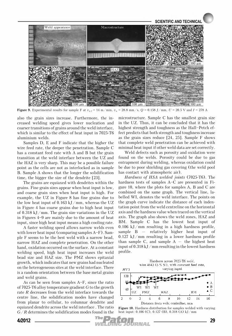
A faster welding speed allows narrow welds evenwith lower heat input (comparing samples A—F). Sam-ple F seems to be the best weld with a narrow bead,narrow HAZ and complete penetration. On the otherhand, oxidation occurred on the surface. At a constantwelding speed, high heat input increases the weldbead size and HAZ size. The PMZ shows epitaxialgrowth, which indicates that new grains had nucleatedon the heterogeneous sites at the weld interface. Thereis a random orientation between the base metal grainsand weld grains.
As can be seen from samples A—F, since the ratioof 7025-T6 alloy temperature gradient G to the growthrate R decreases from the weld interface towards thecentre line, the solidification modes have changedfrom planar to cellular, to columnar dendrite andequiaxed dendrite across the weld interface . The ratioG/R determines the solidification modes found in the
microstructure. Sample C has the smallest grain sizein the UZ. Thus, it can be concluded that it has thehighest strength and toughness as the Hall—Petch ef-fect predicts that both strength and toughness increaseas the grain sizes reduce [24, 25]. Sample F showsthat complete weld penetration can be achieved withminimal heat input if other weld data are set correctly.
Weld defects such as porosity and oxidation werefound on the welds. Porosity could be due to gasentrapment during welding, whereas oxidation couldbe due to poor shielding gas covering (the weld poolhas contact with atmospheric air).
Hardness of HSA welded joints (7025-T6). Thehardness tests of samples A—C are presented in Fi-gure 10, where the plots for samples A, B and C arecombined on the same graph. The vertical line, la-belled WI, denotes the weld interface. The points onthe graph curve indicate the distance of each inden-tation point from the weld centreline on the horizontalaxis and the hardness value when traced on the verticalaxis. The graph also shows the weld zones, HAZ andBM. Sample C has the lowest heat input of0.106 kJ/mm resulting in a high hardness profile,sample B – relatively higher heat input of0.127 kJ/mm resulting in a lower hardness profilethan sample C, and sample A – the highest heatinput of 0.318 kJ/mm resulting in the lowest hardnessprofile.
Figure 9. Experimental results for sample F at vw.f = 14 m/min, vw = 28.8 mm/s, Q = 0.158 J/mm, U = 20.5 V and I = 278 A
Figure 10. Hardness distribution for samples welded with varyingheat input: 0.106 (C), 0.127 (B), 0.318 (A) kJ/mm
4/2012 29

Sample C also has the highest hardness at the WI,thus, implying that high heat input allows for highhardness of the WI, due to solution hardening duringwelding. High heat input causes solubility and therebyhigher hardening through the solidification process.It can also be said that the higher the heat input, thewider the weld bead and the further away from theweld centreline is the WI. The hardness test also showsthis with relatively constant heat input. The hardnesspattern of samples D, E and F are similar, but Eexhibits small variation. The hardness around 3 mmaway from the weld centreline shows a rapid increasein the value from the previous point (around 2 mmfrom the weld centreline). This is due to the closenessof the WI. From samples D, E and F it can be seenthat for 7025-T6 weld, hardness reduces in the weldzone and increases towards the base material. Thehardness graph presents half of the symmetric welds.At the WI it can be said that the hardness values ofD, E and F samples are relatively identical. This im-plies that at constant heat input, the hardness profileof 7025-T6 aluminium alloy remains the same.
The hardness tests of samples D, E and F, presentedin Figure 11, show that the hardness profiles for thethree samples are relatively similar. The WI range iswithin 0.5 mm as a result of a relatively constant heatinput. The labelling and description of the graph isthe same as for samples A—C.
CONCLUSIONS
1. The study showed that in 7025-T6 aluminium alloysthe grain size reduces as the heat input reduces. Thetransition of cells from the UZ to HAZ is smootherwith higher heat input. At constant heat input thegrain size increases when wire feed rate, welding speedand current increase simultaneously but the hardnessremains relatively constant. When heat input is high,the HAZ is wider, nucleation is lower, and the grainsaround the weld interface are coarser.
2. In 7025-T6 aluminium alloy, high heat inputresults in a low hardness profile but the hardness ofthe UZ is the same in all the selected samples. Thehigher the heat input, the wider the weld bead, thefurther away is the weld interface and the deeper theweld penetration. The longer the solidification time,the larger the dendrites and a high cooling rate allowsfor epitaxial cell formation. The 7025-T6 alloy, likeother high-strength aluminium alloys, experiencesHAZ softening but can be restored by postweld heattreatment.
Figure 11. Hardness distribution for samples welded with relativelyconstant heat input of about 0.16 kJ/mm
1. Yeomans, S.R. (1990) Successful welding of aluminium andits alloys. Australian Welding J., 35(4), 20—24.
2. Graeve, I.D., Hirsch, J. (2010) 7xxx series alloys.http://aluminium.matter.org.uk/content/html/eng/default.asp?catid=214&pageid=2144417086
3. Dickerson, P.B., Irving, B. (1992) Welding aluminium: It’snot as difficult as it sounds. Welding J., 71(4), 45—50.
4. Mathers, G. (2002) The welding of aluminium and its al-loys. Boca Raton: CRC Press; Woodhead Publ.
5. Maurice, S. (1997) Aluminum structures: Handbook ofstructural engineering. 2nd ed. CRC Press.
6. Campbell, F.C. (2006) Manufacturing technology for aero-space structural materials. Amsterdam; San Diego: Elsevier.
7. (2008) ASM Handbook. Vol. 15: Casting. Materials Park:ASM Int.
8. Kopeliovich, D. (2009) Classification of aluminum alloys.In: Substances and technology.
9. (2010) MatWeb – The Online Materials Information Re-source.
10. Kaufman, G.J. (2000) Applications for aluminum alloys andtempers. ASM Int.
11. John, D. (1999) Heat-treatable alloys. In: Aluminium de-sign and construction. New York: Taylor & Francis, 301.
12. Aluminum alloys and temper designations 101. Dayco Ind.,1—5.
13. Volpone, L.M., Mueller, S. (2008) Joints in light alloys to-day: the boundaries of possibility. Welding Int., 22(9),597—609.
14. George, E.T., MacKenzie, D.S. (2003) Handbook of alumi-num: Physical metallurgy and processes. New York: MarcelDekker.
15. Renshaw, M. (2004) The welding of aluminium castings. In:Aluminium – light strong and beautiful. A.F.o.S. Africa,11—13.
16. (2008) Choosing shielding gases for gas metal-arc welding.Welding J., 87(4), 32—34.
17. Boughton, P., Matani, T.M. (1967) Two years of pulsed arcwelding. Welding and Metal Fabr., Oct., 410—420.
18. Olson, D.L. (1993) Welding, brazing, and soldering: ASMhandbook. Metals Park: ASM Int.
19. Blewett, R.V. (1991) Welding aluminium and its alloys.Welding and Metal Fabr., Oct., 5.
20. Ba Ruizhang, G.S. (2004) Welding of aluminum-lithium al-loy with a high power continuous wave Nd:YAG laser. IIWDoc. IV-866—04.
21. Hirata, Y. (2003) Pulsed arc welding. Welding Int., 17(2),98—115.
22. Chandler, H. (1999) Hardness testing. Materials Park:ASM Int.
23. Kou, S. (2003) Welding metallurgy. Hoboken: Wiley-Intersci.24. Sato, Y.S., Urata, M., Kokawa, H. et al. (2003) Hall—
Petch relationship in friction stir welds of equal channel an-gular-pressed aluminium alloys. Materials Sci. and Eng. A,354(1/2), 298—305.
25. Vander Voort, G.F., (2004) Metallography and microstruc-tures. Materials Park: ASM Int.
30 4/2012