EXPERIMENTAL PERTURBATIONS TO SAFFMAN-TAYLOR …kondic/capstone/2015/maher_phys_rep_95.pdf ·...
47
EXPERIMENTAL PERTURBATIONS TO SAFFMAN-TAYLOR FLOW K.V. McCLOUD, J.V. MAHER Department of Physics and Astronomy, University of Pittsburgh, Pittsburgh, PA 1.5260, USA EISEWIER AMSTERDAM - LAUSANNE ~ NEW YORK - OXFORD - SHANNON - TOKYO
-
Upload
truonglien -
Category
Documents
-
view
214 -
download
0
Transcript of EXPERIMENTAL PERTURBATIONS TO SAFFMAN-TAYLOR …kondic/capstone/2015/maher_phys_rep_95.pdf ·...

EXPERIMENTAL PERTURBATIONS TO SAFFMAN-TAYLOR FLOW
K.V. McCLOUD, J.V. MAHER
Department of Physics and Astronomy, University of Pittsburgh, Pittsburgh, PA 1.5260, USA
EISEWIER
AMSTERDAM - LAUSANNE ~ NEW YORK - OXFORD - SHANNON - TOKYO

PHYSICS REPORTS
ELSEVIER Physics Reports 260 (1995) 1399185
Experimental perturbations to Saffman-Taylor flow
K.V. McCloud, J.V. Maher
Department of Physics and Astronomy, University of Pittsburgh, Pittsburgh, PA 15260, USA
Received October 1994; editor: I. Procaccia
Contents
1. Introduction 141 3.3. Bubble perturbation and dendrite-like 2. Review of Saffman-Taylor problem 141 structures
2.1. Flow in a channel 141 3.4. Gradient-in-gap experiments 2.2. Radial flow 149 3.5. Grooves and lattices
3. Experiments which add perturbations to 3.6. Temporally varying cell-gaps channel flow 152 3.7. Patterns driven into viscoelastic fluids
155 158 164 171 171
3.1. Single (and double) wire - narrow 4. Conclusions 181 finger selection 153 References 182
3.2. Transverse field effects (gravity) 153
Abstract
Patterns found at driven interfaces add richness and beauty to the visual world, but they build processing-history- dependent inhomogeneities into samples of materials whose usefulness is affected by these inhomogeneities. The Saffman-Taylor (S-T) problem provides a particularly simple case of nonlinear interfacial pattern formation. A wide variety of experiments have added perturbations to the S-T problem in order to learn more about the dynamics of driven interfaces and about the relation of material properties to dynamical pattern evolution.
0370-1573/95/$29.00 0 1995 Elsevier Science B.V. All rights reserved SSDI 0370-1573(94)000113-8
K. V. McCloud, J. V. Maher / Physics Reports 260 (1995) 139-18.5 141
1. Introduction
The viscous fingering problem was first discussed in the 1950s [1,2], but much of our current understanding of the problem stems from work performed in the 1980s with particular progress having been made in understanding the onset and the asymptotic steady state for the two- dimensional Saffman-Taylor flow in a channel. While important questions remain as to the dynamical path leading from onset to steady state, the basic understanding so far achieved has made it possible to extend the problem with the addition of perturbations in the hope of using this simplest of interface-growth problems as a “hydrogen atom” or “fruit fly” problem to learn about wider classes of mathematically related pattern-evolution problems. In this paper we attempt to classify the various perturbation experiments and to review their progress. While it is not possible to separate theoretical from experimental progress, the emphasis in this paper will be on the experiments, their current limitations and their existing contributions. Since thorough and insight- ful reviews are already available for the basic Saffman-Taylor problem [3-73, we will restrict ourselves to a brief review of this problem, with only enough detail to define our notation and set out open questions which currently limit the perturbation experiments.
2. Review of the Saffmarr-Taylor problem
2. I. Flow in a channel
The Saffman-Taylor (S-T) instability in its pure form arises at the initially planar interface between two fluids flowing in a channel of width w in a Hele-Shaw cell, a cell formed by parallel plates separated by a gap whose thickness, b, is smaller than any other length scale in the fluid problem. Fig. 1 illustrates the form of such a cell. When only one liquid is present in the cell, flow forced by pressure gradients or gravity is pure potential flow, and a variety of beautiful examples of two-dimensional potential flow around barriers have been demonstrated with Hele-Shaw cells. The simplicity of this flow arises from the very high resistivity of the cell caused by the very small gap, b. Under these conditions Hele-Shaw [S] showed that the velocity in the center of the gap and the velocity averaged across the full gap in the cell were both proportional to the applied pressure gradient with an effective conductivity b/12p, where p is the viscosity. (This gives Hele-Shaw flow a mathematical kinship with technologically important flows in porous media such as groundwater flows and oil recovery problems, since the velocity/pressure relation is mathematically the same as Darcy’s law for porous media where the analogous conductivity is given by the ratio of the permeability of the medium to the viscosity of the fluid.) If in addition the fluid is incompressible, mass conservation requires that the divergence of the velocity field vanish and leads to a Laplace equation for the pressure field, P. Thus one can set up a potential
where K is the permeability and is equal to b2/12 in this problem, p is the density, p is the angle of the cell with the vertical, and the z axis is directed perpendicularly to the initial interface between

142 K. V. McCloud, J. V. Maher / Physics Reports 260 (1995) 139-185
Fig. 1. The Hele-Shaw cell with two immiscible fluids of distinct densities p and viscosities p. The two fluids have an interfacial tension C.
the two fluids and in the direction of flow. With this potential, the velocity field, u, can be written
u= -v.x (2)
and the continuity equation for mass leads to
v *u = v2x = 0. (3)
Once two immiscible fluids are present in the cell, moving their interface brings nonlinearity into the flow problem. That is, flow in the bulk of each of the fluids is still potential flow governed by Eq. (3), but the physics of the moving interface requires that the normal component of the velocity be continuous across the interface and that the pressure difference across the interface obey the Gibbs-Thompson relations for pressure discontinuities across curved surfaces:
AP = a( l/R1 + l/R,) , (5)
where RI is the radius of curvature for the direction across the gap and is of the order of the gap dimension, b, and R2 is the curvature in the y-z plane. The pressure jump condition (Eq. (5)) poses a particularly thorny problem since the larger of the two contributions to the curvature generally arises from the bending of the moving interface in the direction of the gap, a problem which reintroduces the third spatial dimension. Curvature in this dimension depends sensitively on the wettability of the walls for the fluids and has only been treated quantitatively for the case where the displaced fluid completely wets the plates which form the cell. In that case, the motion of the interface leaves behind a wetting film whose thickness in general depends on the velocity of advance of the interface. The interfacial curvature then depends on the thickness of this wetting layer [9]
K.V. McCloud, J. V. Maher J Physics Reports 260 (1995) 139-185 143
and can be represented as a power series in the velocity:
(6)
where G is the surface tension. With the boundary conditions in this form, there has been impressive success in understanding measurements of the flow [S, 10,111, despite the fact that no treatment has as yet taken into account dissipative work done in advancing the interface along the walls at the sides of the channel.
A moving flat interface can be destabilized by either a viscosity or a density mismatch. After the initial breakup into a serrated pattern dominated by the fastest growing mode from a linear stability analysis, the system eventually evolves into a single finger. This finger has a dimensionless width, 1, which is understandable in terms of capillary effects and the width of the channel (w) and is normally approximately half the width of the channel.
2.1. I. The linear regime
After Saffman and Taylor [l] and Hill [2] had demonstrated the existence of the instability at all wavelengths in the absence of interfacial tension, Chuoke et al. [12] included surface tension and showed that the instability has a dispersion relation for growth rate co as a function of wavenumber k, which can be written as
(7)
This dispersion relation gives exponential growth of microscopic perturbations over a broad band of frequencies corresponding to wavelengths greater than a cutoff wavelength
1, = 2xb (T
1
112
WP2/K2 - PIIKI)(U - UC) (8)
with a critical velocity
n, = C&2 - P~)/(PI - ~2)l(b~/W (9)
and fastest growing mode A,,,,, = fi 1,. The length scales predicted by this dispersion relation have been tested rather thoroughly both
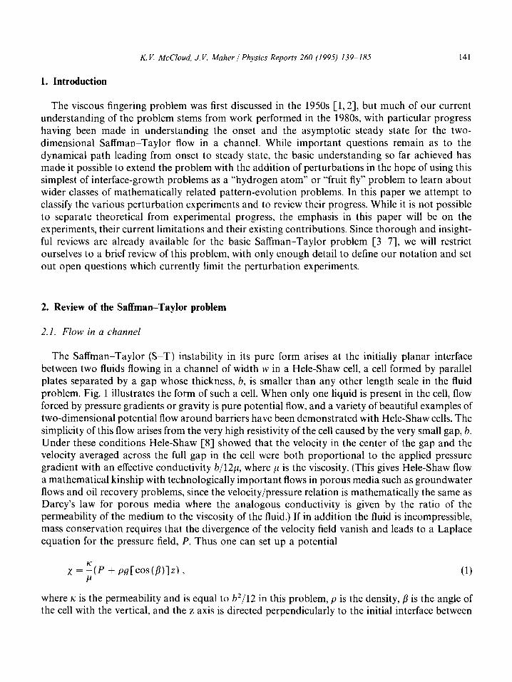
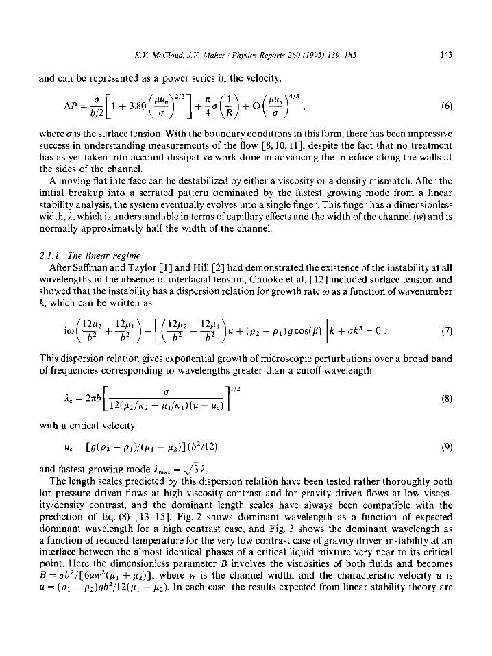
for pressure driven flows at high viscosity contrast and for gravity driven flows at low viscos- ity/density contrast, and the dominant length scales have always been compatible with the prediction of Eq. (8) [ 13-151. Fig. 2 shows dominant wavelength as a function of expected dominant wavelength for a high contrast case, and Fig. 3 shows the dominant wavelength as a function of reduced temperature for the very low contrast case of gravity driven instability at an interface between the almost identical phases of a critical liquid mixture very near to its critical point. Here the dimensionless parameter B involves the viscosities of both fluids and becomes B = ab2/[6uw2(p1 + p2)], where w is the channel width, and the characteristic velocity u is u = (pl - P2)gb2/12(p1 + ,u~). In each case, the results expected from linear stability theory are
144 K. V. McCloud, J. V. Maher / Physics Reports 260 (1995) 139-185
7
/ ,
Fig. 2. Comparison of the observed dominant wavelengths Robs with expected dominant wavelengths A,, for high- viscosity-contrast flows. Reprinted with permission from [14]. Copyright (1984) The Journal of Fluid Mechanics; and with permission from [13]. Copyright (1976) The Soil Society of America Journal.
0.003 0.01 6
Fig. 3. Mean finger wavelength i, versus E, the reduced temperature. Also shown on the upper edge is dimensionless surface tension B (defined in the text and calculated from E using the relation B = O.O22~~~~~(coscr)-~). Reprinted with permission [lS]. Copyright (1989) The Physical Society of America.
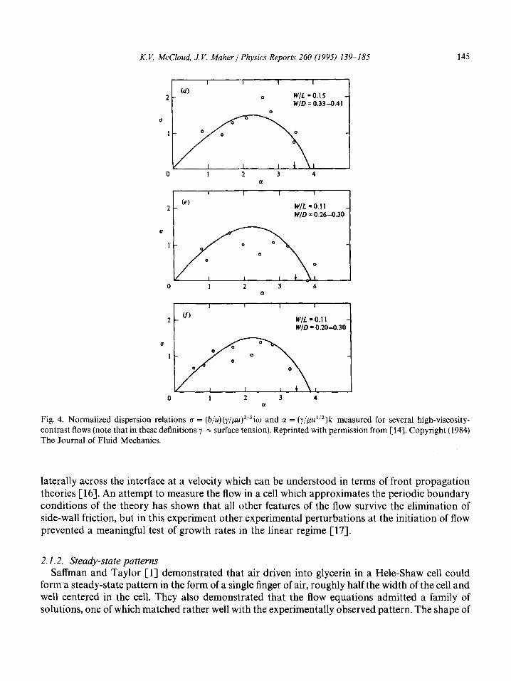
shown as a solid line against the data. Even though the observed length scales on the serrated interface are as the theory would predict, the measured growth rates are in only crude agreement with the theory under observable conditions where the systems might be expected to be in the linear regime. Fig. 4 shows examples of normalized dispersion relations for several high contrast cases. The rough growth rate results may be explained by the observation that the instability is normally initiated by friction at the side-walls of the cell and sets up behind a front which grows
K. V. McCloud, J. V. Maher / Physics Reports 260 (1995) 139-185 145
Cd) 2- 0 W/L = 0.15 W/D =0.33-0.41
0
(e) 2- W/L=O.ll li'/D = 0.26-0.30
a
2 u,
t
W/L = 0.11 W/D = 0.20-0.30
0 I 2 3 4 a
Fig. 4. Normalized dispersion relations r~ = (b/u)(y/p~) ‘13iw and c( = (~/p~“*)k measured for several high-viscosity- contrast flows (note that in these definitions y = surface tension). Reprinted with permission from [14]. Copyright (1984) The Journal of Fluid Mechanics.
laterally across the interface at a velocity which can be understood in terms of front propagation theories [16]. An attempt to measure the flow in a cell which approximates the periodic boundary conditions of the theory has shown that all other features of the flow survive the elimination of side-wall friction, but in this experiment other experimental perturbations at the initiation of flow prevented a meaningful test of growth rates in the linear regime [17].
2.1.2. Steady-state patterns Saffman and Taylor Cl] demonstrated that air driven into glycerin in a Hele-Shaw cell could
form a steady-state pattern in the form of a single finger of air, roughly half the width of the cell and well centered in the cell. They also demonstrated that the flow equations admitted a family of solutions, one of which matched rather well with the experimentally observed pattern. The shape of

146 K. V. McCloud, J. V. Maher / Physics Reports 260 (1995) 139-185
the steady-state finger is given by [l]
X -=+$lnf(l +cos$, W
(10)
where y is the position in the direction parallel to the flow, x is the position across the channel, and A is the ratio of the finger width to the channel width w. Wide fingers are fit slightly better by a relation found by Pitts [lSJ. Fig. 5 shows an example of such a steady state pattern. During the following twenty-five years, the understanding of the stability of single finger patterns and the mechanism of selection of the experimentally observed patterns were subjects of lively discussion, a discussion which has been thoroughly reviewed elsewhere [4,19,22]. In brief, there are a de- numerable infinity of single finger solutions, differing in width and linked tip curvature. The narrowest of these has a width which, once corrected for wetting effects, corresponds to the experimentally observed pattern [20-221. In 1986, three groups simultaneously published demon- strations of the stability of the experimentally observed pattern with all other members of the family of solutions unstable [23-251.
While this steady-state pattern is linearly stable, it can be driven unstable by macroscopic perturbations, with the size of the needed macroscopic perturbation shrinking exponentially with increases in the velocity of the finger tip [11,22,26]. Below the stability limit for macroscopic perturbations in a given cell, the dimensionless finger width i, observed under steady state conditions, is dependent on surface tension and tip velocity. The relation between these can be understood once account is taken both of the capillary effects inherent in the two-dimensional equations (Eqs. (3) and (4), (5)) and the added velocity-dependent effects of curvature across the gap with the cell plate coated with a wetting layer whose thickness depends on local velocity. The capillary number appropriate to the two-dimensional equations is
B = b2a/12puw2 . (11)
The finger width A decreases from about 1 for very low values of l/B, then saturates at about + at high values of l/B (before the finger becomes unstable).
At low velocities where Eq. (6) should be valid, Tabeling et al. [lo] have shown that a good approximate incorporation of plate-wetting corrections can be achieved by defining a corrected capillary number
B* = L-b=+/4 + aA/b(~z&)2’3)]/12~~w2 (12)
Fig. 5. An example of a stable S-T finger in the channel geometry, photographed from above. Taken from [152].

K.V. McCloud, J. V. Maher J Physics Reports 260 (1995) 139-185 147
o.5ovo l/B*
Fig. 6. Relative width 3. of the finger as a function of the renormahzed parameter l/B*, calculated from Eq. (13) with c( = 1.7. 0 - the Saffman-Taylor experiment [l] (aspect ratio w/h = 31.8). l - experimental results obtained with Rhodorsil oil 47VlO [lo] (aspect ratio = 66.5). x - experimental results obtained with Rhodosil oil 47V50 [lo] (aspect ratio = 62.3). Theoretical results of McLean and Saffman [19] are presented as a continuous curve. Reprinted with permission from [lo]. Copyright (1986) The American Physical Society.
where CI is a constant taken to be about 1.7. Fig. 6 shows finger width, 2, versus l/B* from a set of measurements taken by Tabeling and Libchaber [lo]. Sarkar and Jasnow [27] have used micro- scopic solvability theory to take into account the effect of wetting, and obtained a wetting correction term in the pressure jump. When this correction is included in the analysis, the results agree well with the experimental data. Once this capillary correction is taken into account, there is no experimental evidence of any problem with the current understanding of the steady state.
2.1.3. Intermediate dynamical stages While the viscosity contrast between the two driven fluids does not appear in either the steady
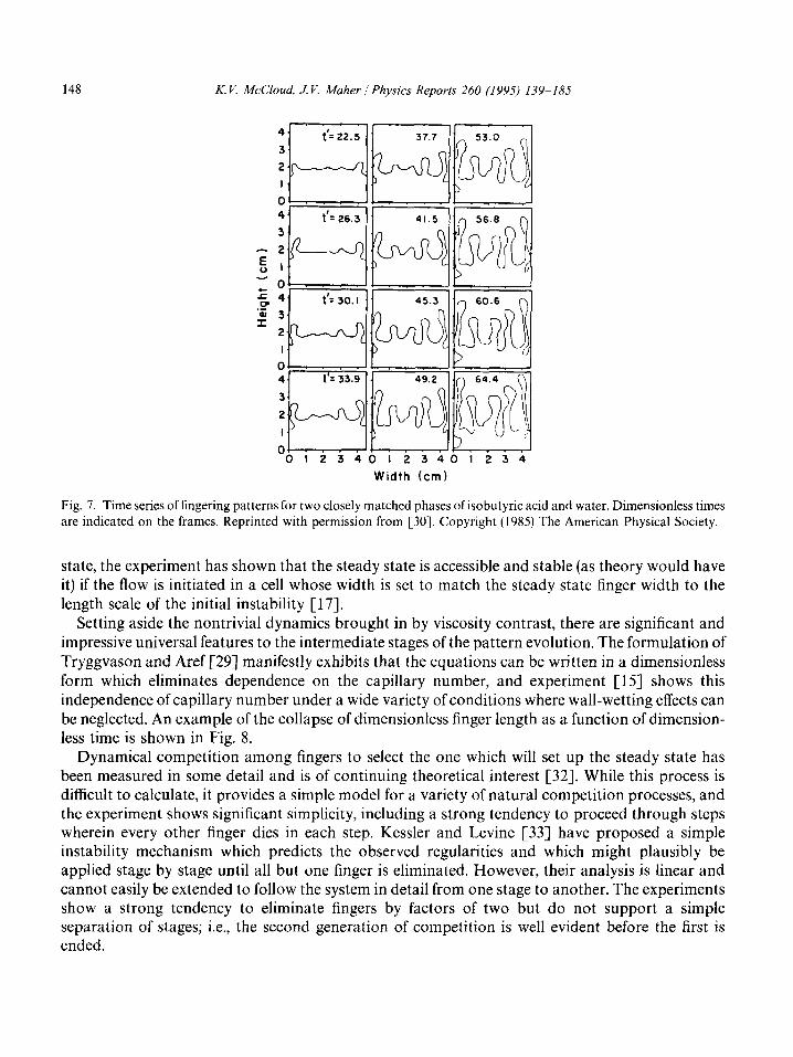
state solution or in the length scale of the initial instability, it does not disappear in the general dynamical problem. Tryggvason and Aref [28,29] have recast the dynamical equations into the form of vortex sheet equations, showing that the capillary number defined in Eq. (11) and the dimensionless viscosity contrast both appear as nontrivial control parameters. Direct numerical integration of their vortex sheet equations has indicated that the dynamical path is indeed strongly dependent on the viscosity contrast. Casademunt and Jasnow [30] have obtained similar results analytically. If there is a high viscosity contrast, the system attains the steady state rather quickly. At low contrast, the calculations show no tendency to reach the steady state at times accessible to the computational technique or even to reduce the initial number of fingers at all. Experiment agrees with the calculations in both limits of viscosity contrast [31]. At low contrast, the measured data track the calculations in all details, keeping the number of fingers constant and the shapes of the fingers elongating with bulbous finger tips and constricting throats until the throats become so narrow that the flow cannot any longer be regarded as two-dimensional (i.e., the throat width becomes comparable to the cell gap), after which the finger tips snap off as bubbles, a stage not accessible to the topologically restricted vortex sheets. An example of a pattern evolution at low contrast is shown in Fig. 7. While three-dimensional effects, which eventually take over the experiments, prevent the experimenter from commenting on whether or not the vortex sheet calculations are valid at later times and whether the system would ever reach the stable steady
148 K. V. McCloud, J. V. Maher / Physics Reports 260 (1995) 139-185
4
3
2
I
0 4
3
-2
E 1
-0 Em 4
‘5 3 I
2
I
0 4
3
2
I
0 012340123401234
Width (cm)
Fig. 7. Time series of fingering patterns for two closely matched phases of isobutyric acid and water. Dimensionless times
are indicated on the frames. Reprinted with permission from [30]. Copyright (1985) The American Physical Society.
state, the experiment has shown that the steady state is accessible and stable (as theory would have it) if the flow is initiated in a cell whose width is set to match the steady state finger width to the length scale of the initial instability [17].
Setting aside the nontrivial dynamics brought in by viscosity contrast, there are significant and impressive universal features to the intermediate stages of the pattern evolution. The formulation of Tryggvason and Aref [29] manifestly exhibits that the equations can be written in a dimensionless form which eliminates dependence on the capillary number, and experiment [lS] shows this independence of capillary number under a wide variety of conditions where wall-wetting effects can be neglected. An example of the collapse of dimensionless finger length as a function of dimension- less time is shown in Fig. 8.
Dynamical competition among fingers to select the one which will set up the steady state has been measured in some detail and is of continuing theoretical interest [32]. While this process is difficult to calculate, it provides a simple model for a variety of natural competition processes, and the experiment shows significant simplicity, including a strong tendency to proceed through steps wherein every other finger dies in each step. Kessler and Levine [33] have proposed a simple instability mechanism which predicts the observed regularities and which might plausibly be applied stage by stage until all but one finger is eliminated. However, their analysis is linear and cannot easily be extended to follow the system in detail from one stage to another. The experiments show a strong tendency to eliminate fingers by factors of two but do not support a simple separation of stages; i.e., the second generation of competition is well evident before the first is ended.

K. V. McCloud, J. V. Maher / Physics Reports 260 (1995) 139-185 149
1: --I .+ 0
.X” +
l 0
10-l : - ;Y
f : I , ,,I , , ,L
’ t(s) ‘O 100 10
1 1’
IO 100
Fig. 8. Dimensionless stretching arclength (a) L’ versus t in seconds for flows differing in B only; (b) L’ versus t’, dimensionless time. Reprinted with permission from [31]. Copyright (1989) The American Physical Society.
2.2. Radial flow
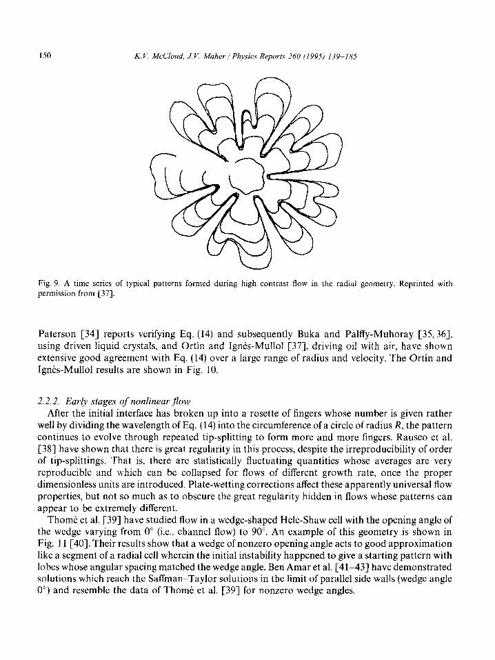
When an interface between immiscible fluids is driven radially through a Hele-Shaw cell, instability can again result if the viscosity contrast involves the less-viscous driving the more- viscous fluid. Paterson has performed the linear stability analysis and has made measurements which demonstrate good agreement with his analysis [34]. Later stages of the flow are less well understood than those of the channel flow. Lacking a second length scale analogous to the width of the channel, the radial flow shows continued stages of front breakup with no true steady state attainable. Fig. 9 shows a time series of patterns developing in such a flow. As with the channel flow, the flow in each of the immiscible fluids is Laplacian and all nonlinearity arises from the boundary conditions given by Eqs. (4) and (6).
2.2.1. Breakup of the initial circle If the flow begins with a circular interface advancing at velocity V, Paterson [34] has shown that
the fastest growing unstable mode (n,) depends on both radius R and the injection rate Q as
n “, = [+ (QR/2mczo + l)]“’
with a broad band instability whose shortest unstable wavelength is
(13)
A, = 2&R
[(QR/2mc,0 + 1/4)“2 - l/2] (14)
150 K. V. McCloud, J. V. Maher / Physics Reports 260 (1995) 139-185
Fig. 9. A time series of typical patterns formed during high contrast flow in the radial geometry. Reprinted with permission from [37].
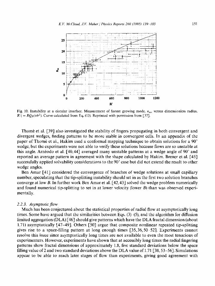
Paterson [34] reports verifying Eq. (14) and subsequently Buka and Palffy-Muhoray [35,36], using driven liquid crystals, and Ortin and Ignes-Mullol [37], driving oil with air, have shown extensive good agreement with Eq. (14) over a large range of radius and velocity. The Ortin and Ignes-Mull01 results are shown in Fig. 10.
2.2.2. Early stages of nonlinear $0~
After the initial interface has broken up into a rosette of fingers whose number is given rather well by dividing the wavelength of Eq. (14) into the circumference of a circle of radius R, the pattern continues to evolve through repeated tip-splitting to form more and more fingers. Rauseo et al. [38] have shown that there is great regularity in this process, despite the irreproducibility of order of tip-splittings. That is, there are statistically fluctuating quantities whose averages are very reproducible and which can be collapsed for flows of different growth rate, once the proper dimensionless units are introduced. Plate-wetting corrections affect these apparently universal flow properties, but not so much as to obscure the great regularity hidden in flows whose patterns can appear to be extremely different.
Theme et al. [39] have studied flow in a wedge-shaped Hele-Shaw cell with the opening angle of the wedge varying from 0” (i.e., channel flow) to 90”. An example of this geometry is shown in Fig. 11 [40]. Their results show that a wedge of nonzero opening angle acts to good approximation like a segment of a radial cell wherein the initial instability happened to give a starting pattern with lobes whose angular spacing matched the wedge angle. Ben Amar et al. [41-431 have demonstrated solutions which reach the Saffman-Taylor solutions in the limit of parallel side walls (wedge angle 0’) and resemble the data of Theme et al. [39] for nonzero wedge angles.
K. V. McCloud, J. V. Maher / Physics Reports 260 (1995) 139-185 151
d
0 200 400 600 800 1000 1200
R’
Fig. 10. Instability at a circular interface. Measurement of fastest growing mode, n,, versus dimensionless radius, R’( = RQp/crb’). Curve calculated from Eq. (13). Reprinted with permission from [37].
Theme et al. [39] also investigated the stability of fingers propagating in both convergent and divergent wedges, finding patterns to be more stable in convergent cells. In an appendix of the paper of Theme et al., Hakim used a conformal mapping technique to obtain solutions for a 90” wedge, but the experiments were not able to verify these solutions because flows are so unstable at this angle. Arneodo et al. [40,44] averaged many unstable patterns at a wedge angle of 90” and reported an average pattern in agreement with the shape calculated by Hakim. Brener et al. [45] successfully applied solvability considerations to the 90” case but did not extend the result to other wedge angles.
Ben Amar [41] considered the convergence of branches of wedge solutions at small capillary number, speculating that the tip-splitting instability should set in as the first two solution branches converge at low B. In further work Ben Amar et al. [42,43] solved the wedge problem numerically and found numerical tip-splitting to set in at lower velocity (lower B) than was observed experi- mentally.
2.2.3. Asymptotic flow
Much has been conjectured about the statistical properties of radial flow at asymptotically long times. Some have argued that the similarities between Eqs. (3)-(5), and the algorithm for diffusion limited aggregation (DLA) [46] should give patterns which have the DLA fractal dimension (about 1.71) asymptotically [47-493. Others [SO] argue that composite nonlinear repeated tip-splitting gives rise to a space-filling pattern at long enough times [35,36,50-521. Experiments cannot resolve this issue since asymptotically long times are not available to even the most tenacious of experimenters. However, experiments have shown that at accessibly long times the radial fingering patterns show fractal dimensions of approximately 1.8, five standard deviations below the space filling value of 2 and two standard deviations above the DLA value of 1.71 [38,53-561. Simulations appear to be able to reach later stages of flow than experiments, giving good agreement with

152 K. V. McCloud, J V. Maher / Physics Reports 260 (199.7) 139-185
Fig. 11. Unstable viscous fingers obtained in an angular cell with 19~ = 60”. Reprinted with permission from [40]. Copyright (1990) Plenum Press.
experiment at early times and tending extremely slowly toward space-filling patterns at later times [52,57-621.
3. Experiments which add perturbations to channel flow
In recent years, a number of experiments have exploited the simplicity of the Saffman-Taylor steady state finger by adding perturbations and trying to understand the resulting changes in the flow patterns. Some of these experiments involved perturbations which could be written rather confidently in mathematical form, while others could only qualitatively be incorporated into the

K. V. McCloud, J. V. Maher 1 Physics Reports 260 (1995) 139-185 153
dynamical equations. We review them here in an arbitrary order, largely historical but designed to bring out the contributions of each approach and to articulate the current state of understanding.
3.1. Single (and double) wire - narrow jinger selection
While the unperturbed S-T finger selects the unique solution discussed above, other members of the ST family of solutions can be selected if perturbations are added to the flow. In the simplest of these a wire is placed between the plates of the cell parallel to the flow direction [63]. If the wire is close to the side of the cell, no change is induced in the solution, whether or not the wire intersects the finger, although there is a small kink in the finger at the point of penetration by the wire. However, if the wire is close to the center of the cell, a narrower solution is selected. This narrower finger is no longer necessarily centered in the cell. Rather, it is shifted to the side of the cell occupied by the wire, and apart from a local bump caused by the wire, the shape of the finger follows the shape of the S-T solution with the selected value of A, where A is the ratio of the finger width to the cell width. Fig. 12 shows the effect of wires placed at differing points in the cell. While the selected value of 1 depends weakly on the diameter of the wire, it always appears to be smaller than the width of the unperturbed finger and the pattern always has the S-T shape. Simulations and analytic arguments suggest that the crucial feature of this perturbation is that the wire allows an abrupt change in the curvature of the finger, permitting the otherwise unselected S-T solutions to avoid the destabilizing cusp-like singularity which is believed to make these solutions unphysical in the unperturbed problem [64-681. The fingers also adjust themselves to place the finger tip a distance 6 from the wire which scales as a power of the velocity over a factor of approximately 30 in the dimensionless number B; i.e., over B values from 0.0001 to 0.003, the displacement 6 is observed to vary with the finger tip velocity u as 6 - U-~ with c( = 0.40 + 0.04. The thin, perturbed fingers are also observed to be much more stable than the unperturbed solution characteristic of a given cell. In the case of Zocchi et al. [63], the stability limit of the cell was extended by more than a factor of 10 in l/B when the wire perturbation was added, as shown in Fig. 13. The addition of a second wire symmetrically placed in the cell a distance D from the first was also instructive [63], in that a symmetric solution, also narrower than the unperturbed solution, was observed at velocities below a value set by the magnitude of D. Once this limiting velocity was exceeded, the finger selected one or the other of the wires and formed a narrowed, asymmetric solution which ignored the unfavored wire (i.e., the narrow finger was the same as if the selected wire were the only one in the cell).
Rabaud et al. [69] have done a rather complete study of the effect of different perturbations on the S-T finger. First they observed the effects of two grooves etched on the surface of a cell. There was not a great deal of distortion due to the grooves; the finger tip placed itself between the two grooves, and the finger was slightly sharper. They next stretched a thread along the cell and found that the finger acts to place the thread at a certain spot relative to the tip. As with the wire experiment [63], moving the thread from the center of the cell can result in asymmetric fingers.
3.2. Transverse field eficts (gravity)
Asymmetric steady fingers can also be produced by the application of a field normal to the S-T flow direction. This was initially predicted by Brener et al. [70] for fingers grown in a Hele-Shaw

154 K. V. McCloud, J. V. Maher / Physics Reports 260 (1995) 139-185
(b)
(e)
Fig. 12. Steady state fingers of air penetrating into oil. (a)-(d) a nylon wire with a diameter of 117 urn is suspended inside the cell; (e) a 13 urn thick tungsten wire is used. (a) l/B = 3160, d = 0.482; the wire does not intersect the interface, and there is no effect on the shape. (b) l/B = 3000, /1 = 0.481; the wire intersects the cell far away from the tip, and still there is no effect on the overall shape. (c) l/B = 2510, i = 0.402; the wire intersects the interface near the tip, and the finger width is dramatically changed. (d) l/B = 17200. 1, = 0.296. The shape is asymmetric because the finger is not moving in the center of the channel. (e) l/B = 28300, i = 0.300. Reprinted with permission from [63]. Copyright (1987) The American Physical Society.
cell tilted from the horizontal by an angle co, such that gravity acts across the cell, perpendicular to the direction of flow. More recently, Brener et al. [71] have performed experiments to investigate the same transverse-gravity case. The experiments observed narrow, asymmetric fingers whose width decreased with increasing capillary number B, while their degree of asymmetry increased with B, as shown in Fig. 14. At constant B, the finger width decreased and the degree of asymmetry increased with increasing tilt angle. The stability of the fingers was observed to increase with increasing tilt angle, o. The experiments [71] also showed rough agreement with scaling laws developed in the theoretical work [70] for the B + 0, w --t 0 limit. The experimental fingers were always less asymmetric at the tips than the theoretical work had predicted, probably a result of finite surface tension. Reasonable agreement was found between the experimentally observed distance from finger to side-wall and predictions in the large-B limit.

K. V. McCloud, J. V. Maher / Physics Reports 260 (1995) 139-185 155
I ’ I ’ I
0.8 -
~;~_---_____________
.P, 0 N-3. 0 a
-.. . . .9. ..o... 0 . ..-
Fig. 13. Finger width iL versus l/B. + ~ unperturbed case; 0 ~ perturbed with a tungsten wire 13 urn thick; 0 - perturbed with a nylon wire 117 urn thick. In each case, data are shown to the stability limit. Reprinted with permission from [63]. Copyright (1987) The American Physical Society.
0.2 p : _ 01 9’ I 0 1 0 b’, 0 5.0 10' 1.0 lo-' B 1.5 ii? 2.0 16)
' 0
0.1 - 4 c 'bA
A A A a) 0 I
0 5.0 up 1.0 IO' I.5 IO' 2.0 IO'
B Fig. 14. Evolution of the width 1 (a) and y, (b) versus B for different tilt angles: w = 0” (O), (r) = 2.2” ( 0 ), w = 5.06” ( W), w = 10” ( q ), and Q = 90° (A). Reprinted with permission from [71]. Copyright (1993) The American Physical Society.
3.3. Bubble perturbation and dendrite-like structures
Some and possibly all of the wire-perturbation work just described was inspired by the observation of a very dramatic change in the S-T finger when a bubble of gas was trapped in the cell just in front of the advancing finger [72,73]. As the finger pushed the bubble forward in front of the finger tip, the formerly smooth sides of the finger became unstable and formed side structures which closely resemble the oscillations growing behind the tip of an advancing dendrite in the solidification problem. An example taken from Couder et al. [72] is shown in Fig. 15. Close inspection showed that these structures were correlated with shape oscillations of the driven bubble

156 K. V. h&Cloud, J. V. Maher/ Physics Reports 260 (1995) 139-185
Fig. 15. Pattern obtained in a cell with b = 0.04cm and D = 1.6 cm/s. The scale at the bottom of the picture is graduated in cm. The velocity of growth of the dendritic finger is 1.8 times the velocity of the other fingers. Reprinted with permission from [72]. Copyright (1986) Les Editions de Physique.
and that, as in the solidification problem, they did not originate at the side of the finger but rather they formed near the tip with very low amplitude and grew to observable amplitude as the growing finger swept by them and left them on its sides. While the coupling of the finger to the allowed oscillatory modes of the driven bubble is a very difficult problem, the similarity of the resulting pattern to dendrite formation in the solidification problem and the mathematical similarity of the S-T problem to simplified versions of solidification provided impetus for much work to try to connect the solidification problem to more tractable perturbed S-T experiments.
Rabaud et al. [69] also studied the tip region of a finger preceded by a bubble in a channel and found that the tip shape was the same as for their work on threads and grooves discussed in Section 3.1, with the exception of the tip region where the thread, etc., actually touched the
K. V. McCloud, J. V. Maher 1 Physics Reports 260 (1995) 139-185 157
interface of the finger. They then looked at the dimensionless radius of curvature p/b as a function of the dimensionless capillary number Bw2/b2, and found two regimes. For a large range of velocities, the dimensionless tip radius is proportional to BwZ/b2, but at sufficiently high velocities, the dimensionless tip radius becomes constant. The first regime corresponds to the relation pu2 = constant. The second corresponds to a saturation in the value of 13. similar to the well-known k = + saturation, but caused by the fact that p has become of the same order as b, and the two-dimensionality of the problem has broken down. Hong and Langer [64] have suggested that the effect of a bubble at the tip of an S-T finger is to allow a nonzero mismatch angle. They have shown that there is a solvability condition which depends on the mismatch angle and gives the usual S-T finger for a mismatch angle equal to zero. For a positive mismatch angle, the solvability condition can be satisfied by steady state fingers of fractional width i less than i. If the assumption that the mismatch angle depends only on the velocity of the finger is allowed, the results of the experiments compare well with the theory.
Combescot and Dombre [74] studied the theoretical effect of a bubble in front of a growing ST finger. They solved the S-T equations for a finger with a bubble in front of it for zero surface tension, found a new family of solutions, and used solvability criteria to get the shape of the selected finger and the relationship between the finger width and the distance D to the bubble in front of the finger. They then looked at the experimentally observed case of a bubble attached to the tip of a finger and considered the bubble and finger to be a single interface with a cusp at the point where the two meet, and showed that fingers with i < i are allowed in this case. Theme et al. [75] checked the predictions of Combescot and Dombre [74] for a bubble in front of a finger by using a small iron disk which could be moved by a magnet to create the effect of a bubble at a certain distance from a finger. They found good agreement with the predictions of Combescot and Dombre for the relation between the distance between the bubble and the width of the finger.
Theoretical approaches have frequently regarded bubble perturbations and macroscopic wire perturbations as essentially the same. In 1988 Hong [65] expanded the work of Hong and Langer [64] to include the effect of wires, which would produce a negative mismatch angle. Hong postulated that, in the case of two wires, there is a critical mismatch angle above which the finger becomes unstable and jumps to the asymmetric case. In 1989 [66] Hong again extended the theory for wires, and showed that a cusp in the finger boundary (the same as a negative mismatch angle) is necessary to produce narrow, asymmetric fingers. His linear theory predicted that the width of the finger with a wire perturbation is the same as that for a finger with a bubble if the velocity, etc., are held the same, as seen in experiment [63]. He also developed a prediction for the placement of the finger tip with respect to the wire as a function of the finger width and the degree of asymmetry. This prediction agrees well with the experiments of Zocchi et al. [63].
Shaw [67] did an extensive analysis of the effect on an S-T finger of varying the strength of the surface tension at the tip (allowing local minima and maxima). He found that local minima in the surface tension lead to symmetric, narrow fingers while local maxima lead to asymmetric narrow fingers. The surface tension parameter is locally a maximum or minimum at only one or two places on the tip, corresponding to the effect of either a bubble or a wire on the finger.
Guo and Hong [68] have done a random walk simulation of the solvability theory for wires and bubbles. They obtained a relationship between the mismatch angle (discussed above), and the form of the surface tension parameter 0 + o[l - A&?(q)], w h ere 6 is the delta function and q is the

158 K. V. MeCloud, J. V. Maher / Physics Reports 260 (199.5) I39- I85
tangential slope on the finger profile. When incorporated in a random walk simulation of the growth of an S-T finger, this surface tension parameter resulted in narrow fingers.
The results discussed in this section suggest a strong dependence on local flaws in a Hele-Shaw cell, a dependence which forces great care on the experimenter lest cell roughness or cell deformity result in uncontrolled and poorly understood pattern development [l 11. Theme et al. [39], May and Maher [SS], and Van Damme [77] have all discussed the need for care in avoiding anomalous effects from inadequately rigid cells flexing under the application of pressure to produce dynam- ically varying gaps. The next few sections contain discussions of patterns formed in purposefully roughened cells and cells with a smoothly varying gap.
3.4. Gradient-in-gap experiments
If the plates which form a Hele-Shaw cell are not exactly parallel, very significant changes are introduced [76] in both the flow equations and the boundary conditions. These bring the equations much closer to those of solidification, yet they obviously must reduce to the Hele-Shaw results in the limit of small enough perturbation since no real cell can have perfectly parallel plates and too many real cells have demonstrated good agreement with S-T. Two distinct kinds of experiments have tried to exploit this insight. In one a linear gradient is designed into the gap along the direction of channel flow in the Hele-Shaw cell [78]. In the other, two paraxial cylinders are set to have a very small gap at one azimuthal angle. This latter case is for historical reasons called the printers’ instability. Both experiments appeal to essentially the same set of growth equations presented below. The first case has the advantage that the apparatus should come very close to the exact assumptions which lead to the equations. The second has the advantage that steady state flows are attainable over very long periods of time.
Once a gradient has been added to the Hele-Shaw gap, the mobility which relates the velocity field to potential gradient in the Darcy law becomes a spatially varying quantity. The incompressi- bility requirement which, by demanding that the divergence of the velocity vanish, gives rise to a Laplace equation in the S-T case (Eq. (3)) now becomes more complicated, yielding both a Laplacian term and a term which contains an inner product of the potential gradient and the gradient of the mobility. Thus, if we write the gap in a cell whose flow will be in the z direction as
b(z) = b + b’z (15)
where b’ is the gradient of the gap, which can be either positive or negative, then the mobility will be
A4 = [b(z)12/12fi
and the Darcy law will
U = - M(VP) .
be
(16)
(17)
This gives rise to a growth law
(18)
K. V. McCloud, J. V. Maher J Physics Reports 260 (1995) 139-185 159
where 1n(z) = b(z)/(3b’). This growth law is identical to the growth law for directional solidifi- cation. Similarly, the boundary conditions will be modified both by the changing curvature implied by a changing gap and by the difference in conserving mass while requiring continuity of the normal component of velocity across the interface. If one assumes complete wetting, then Eq. (5) above can be straightforwardly modified to give
Pi=OiC-6&. (19)
We have left the coefficient c adjustable to allow complete wetting by either the invading or the driven fluid via a sign change. In the case that the invading fluid completely wets the cell walls, this boundary condition is exactly the same as is found in directional solidification. (It should be noted that although complete wetting was assumed, the velocity-dependent part of the wetting correction in the pressure jump discussed in Sections experiments have been performed only with by the driven fluid. The velocity continuity
2.1 and 2.1.2 has not been included here.) Thus far, the opposite sign, corresponding to complete wetting equation can be written as
(20)
where p is defined to be p = Pb,/( 121/,~), and t(x,t) = zi(x,t) - zO(t) is the deviation of the interface zi(x, t) at position x and time t, from the average interface position zo. The capillary length do is defined to be do = 0b~/l2~~. Eq. (20) is the only one which is clearly different from that of directional solidification. In directional solidification, the term on the right-hand side would not contain the term +(5/l,,).
3.4.1. Uniform gradient flows Experiments with a linear
instability and for changes gradient cell [78] have in the S-T finger at
provided results for both the onset of the late times. A linear stability analysis of
Eqs. (18)-(20) leads to a dispersion relation for the breakup of an initially flat interface of the form
w(k) = & D i(
1-F - d,b,k2 [s(ln) + Id-1 - $(rn) D > 1
(21)
where S(1,) is the sign of ln and all other quantities are as defined above [78]. This dispersion relation reduces to the normal ST relation (Eq. (7)) in the limit of vanishing gap-gradient, and predicts a very gradual onset of departures from the ST case when the gradient becomes nonzero. An experiment [78] has been performed at several very small but well-measured values of the gradient in a range where the equation predicts that effect of the gradient should be unmeasurably small. This experiment has produced two puzzling results: (1) The effect of imposing the gradient is dramatically larger than predicted by Eq. (21). Fig. 16 shows initially wavelengths for five different values of the gap-gradient along with a solid line for the fastest growing wavelength from Eq. (21) (indistinguishably different to the eye for these different cases) and a dashed line for the cutoff wavelength (again the same on the scale of the drawing for all five cases). While the zero-gap case (triangles) agrees well with the dispersion relation, as was reported above for all available S-T

160 K. V. McCloud, J. V. Maher / Physics Reports 260 (I 995) 139- 185
- 7 b, o b’=
.d=- 1.5~10~
0 b'= 3.0X1Ci3
. b'z-3.0~16~ I Y i
‘0 I I 1 J
3 6 9 12 f5
1 CT&V0 Y2
Fig. 16. Scaled data of &, versus a/~ct‘~ for five different gap-gradients and many different initial cell-gaps. The solid line is the fastest-growing mode for all cases and the dashed line is the calculated value of the cutoff mode for all cases. Reprinted with permission from [78]. Copyright (1992) The American Physical Society.
experiments, dimensionless gradients of 1.5 (filled circles) and 3.0 (squares) parts per thousand result in significant changes in observed wavelength, in some cases even exceeding the limit posed by the cutoff wavelength prediction. (2) The observed wavelength for the initial departure from a flat, advancing interface is not dependent on the sign of the gap-gradient, and is altered from the S-T case only by the gradient’s magnitude. Neither of the two observations just described has been explained as yet. The linear stability theory works well for the pure S-T case, and the approxima- tions made in the dynamical equation and the boundary conditions (Eqs. (18))(20)) are parti- cularly plausible for the onset of the instability where the gap is not much changed from the initial value. Understanding this discrepancy where the equations can be written down plausibly in an exact form might provide an opportunity to gain greater understanding of this class of growth equations.
Using Eqs. (15))(20) for understanding later stages of channel flow with a gap-gradient is less easy because the departure of the gap from its initial value in Eq. (15) should build up and become an important correction to the calculation of the evolving patterns. However, experiments have been performed to measure the effect on the ST steady state of adding a gradient. Since the gap changes uniformly in the cell and the true S-T steady state is a function of the gap-magnitude, there should be and presumably is no steady state to the perturbed problem. On the other hand, the relatively easy observation of the S-T state in real cells indicates that this state is robust against very small departures from zero gradient. In fact, it is well understood that the macroscopic perturbation needed to destabilize the S-T finger is large at small velocity (see Section 2.1.2). Experiments with a gap-gradient added show a very regular effect of the gradient on the quasi-steady state seen at late stages of the flow: (1) positive gradient produces a wider finger with a flatter finger tip, and this finger becomes unstable at much lower velocities than for zero gradient; (2) negative gradient produces a narrow finger with a sharper finger tip, and this finger stays stable up to much higher velocities that those needed to destabilize the true S-T finger in a parallel plate
K. V. McCloud, J. V. Maher / Physics Reports 260 (199.5) 139-185 161
-4 -2 0 2
b’ -P x10
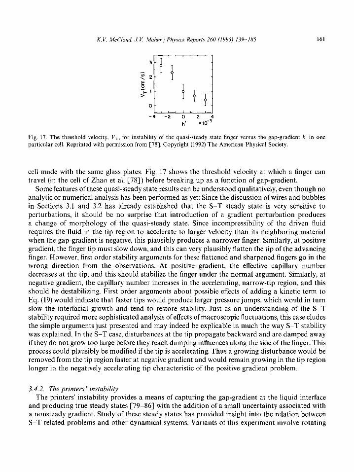
Fig. 17. The threshold velocity, I/ T, for instability of the quasi-steady state finger versus the gap-gradient b’ in one particular cell. Reprinted with permission from [78]. Copyright (1992) The American Physical Society.
cell made with the same glass plates. Fig. 17 shows the threshold velocity at which a finger can travel (in the cell of Zhao et al. [78]) before breaking up as a function of gap-gradient.
Some features of these quasi-steady state results can be understood qualitatively, even though no analytic or numerical analysis has been performed as yet: Since the discussion of wires and bubbles in Sections 3.1 and 3.2 has already established that the S-T steady state is very sensitive to perturbations, it should be no surprise that introduction of a gradient perturbation produces a change of morphology of the quasi-steady state. Since incompressibility of the driven fluid requires the fluid in the tip region to accelerate to larger velocity than its neighboring material when the gap-gradient is negative, this plausibly produces a narrower finger. Similarly, at positive gradient, the finger tip must slow down, and this can very plausibly flatten the tip of the advancing finger. However, first order stability arguments for these flattened and sharpened fingers go in the wrong direction from the observations. At positive gradient, the effective capillary number decreases at the tip, and this should stabilize the finger under the normal argument. Similarly, at negative gradient, the capillary number increases in the accelerating, narrow-tip region, and this should be destabilizing. First order arguments about possible effects of adding a kinetic term to Eq. (19) would indicate that faster tips would produce larger pressure jumps, which would in turn slow the interfacial growth and tend to restore stability. Just as an understanding of the S-T stability required more sophisticated analysis of effects of macroscopic fluctuations, this case eludes the simple arguments just presented and may indeed be explicable in much the way S-T stability was explained. In the S-T case, disturbances at the tip propagate backward and are damped away if they do not grow too large before they reach damping influences along the side of the finger. This process could plausibly be modified if the tip is accelerating. Thus a growing disturbance would be removed from the tip region faster at negative gradient and would remain growing in the tip region longer in the negatively accelerating tip characteristic of the positive gradient problem.
3.4.2. The printers ’ instability The printers’ instability provides a means of capturing the gap-gradient at the liquid interface
and producing true steady states [79-861 with the addition of a small uncertainty associated with a nonsteady gradient. Study of these steady states has provided insight into the relation between S-T related problems and other dynamical systems. Variants of this experiment involve rotating

162 K. V. McCloud, J. V. Maher/ Physics Reports 260 (1995) 139 185
a cylinder near the surface of a planar plate [79,80,101-1031, rotating two solid rollers with a small gap between them [1044109], or rotating two paraxial cylinders with a small gap along a line parallel to their axes [81-861. Equations like Eqs. (15)-(20) still form an approximation to the dynamics and boundary conditions when a viscous fluid is placed in the gap and one or both of the cylinders are rotated. Just as addition of a stabilizing temperature gradient can turn the dendritic MullinsSekerka solidification problem into the stable front growth of low velocity directional solidification, with regular cellular patterns forming as the growth rate increases to exceed a critical value, so in the printers’ instability the pressure field supplied by the gap-gradient changes the ST pattern into a stabilized front at low enough velocities with regular cellular patterns intervening as a critical velocity is exceeded. In general, the front face (that at which the rotation tends to drag the viscous fluid into the gap) remains stable while the rear face is stable only at small values of the angular velocity [102]. If only one cylinder is rotated, above a critical velocity V,, which is dependent on the cell-gap the rear interface breaks up and, after a sometimes long dynamical process, eventually settles into a cellular pattern with a characteristic wavelength which depends on both the rotational velocity and the cell-gap. This instability is supercritical: near threshold the patterns are sinusoidal with amplitude which grows from zero as (V - V,)“.5 and turns to cells with S-T-like fingers separated by deep, narrow grooves at high velocities, as shown in Fig. 18. While transients can be slow to deliver the system to its steady state, no hysteresis is observed if the steady state is patiently awaited, and the wavelength of the steady state is very regular even when the pattern contains a very larger number of cells ( - 100) [83,102]. Early experiments of this type were motivated by problems caused by this instability in the paint and print industries, problems which could depend on either transient or steady state behavior depending on the details of operation of the roller apparatus. However, the more recent experi- ments have focused on the steady state and have found a rich variety of patterns available depending on the choice of cylinder velocities. As mentioned above, the cellular patterns which appear and are stable above the onset of instability closely resemble cellular patterns observed in directional solidification. The steady state wavelengths of these cellular patterns are close to but definitely different from the prediction of linearized equations, a result which might arise from the departure of the gap-gradient from the constant value assumed in the calculations or one that might arise from more interesting dynamical issues (recall that the transient pattern at the breakup of a flat interface in a truly constant-gradient gap also departs from the predictions of the equations for as yet unknown reasons). Abrupt changes in the rotational velocities of the rotating cylinders can produce interesting transient patterns as the system finds its way from one cellular steady state to another. In particular, simultaneous splitting of all tips has been observed when the change was just right to have the wavelength of the pattern [83]. Transients are generally faster if the wavelength is reduced (velocity increased) and, depending on the ratio of liquid depth (local gap at the interface) to pattern wavelength, can occur via propagation of travelling asymmetric waves or via the nucleation of anomalously wide waves [83]. While the wavelength selection in this problem shows much smaller dispersion than do typical directional solidification experiments, the ability to wait for the damping of long transients is greater in this problem, suggesting that the limited pulling time of directional solidification experiments may restrict their ability to reach a true steady state.
In the two-cylinder version of the printers’ instability, it is possible to rotate both cylinders simultaneously [81,82,84-861. In this case the front interface is still always stable, but the back interface need not necessarily from cellular patterns. Both spatiotemporal chaos [84,85,109],

K. K McCloud, J. V. Maher / Physics Reports 260 (1995) 139-185 163
Fig. 18. Sequence of pictures of the steady state interface for increasing velocity, in a cell of thickness b0 = 0.17 mm. The line at the top of each picture is the front meniscus, at the bottom the back meniscus. (a) V, = 31.5 mm/s, (b) V0 = 32.8 mm/s, (c) V, = 67 mm/s, (d) V0 = 185 mm/s. Reprinted with permission from [102]. Copyright (1988) Plenum Press.
travelling cell solutions [86] and solitary waves have been observed at various points on the dynamical phase diagram formed in the plane of the two rotational velocities [82]. This dynamical phase diagram is shown in Fig. 19.
164 K. V. McCloud, J. V. Maher 1 Physics Reports 260 (1995) 139-185
150
2
s x
> 0
-150
-100 0
o,3_:/ 8 ‘i+ 8
Faceted A 1 Tip-Spttting ‘\f&ttas
I ‘L 01 \
DL2 *
0 .l Atm APPLIED
100 PRESSURE
Vl(mm/s)
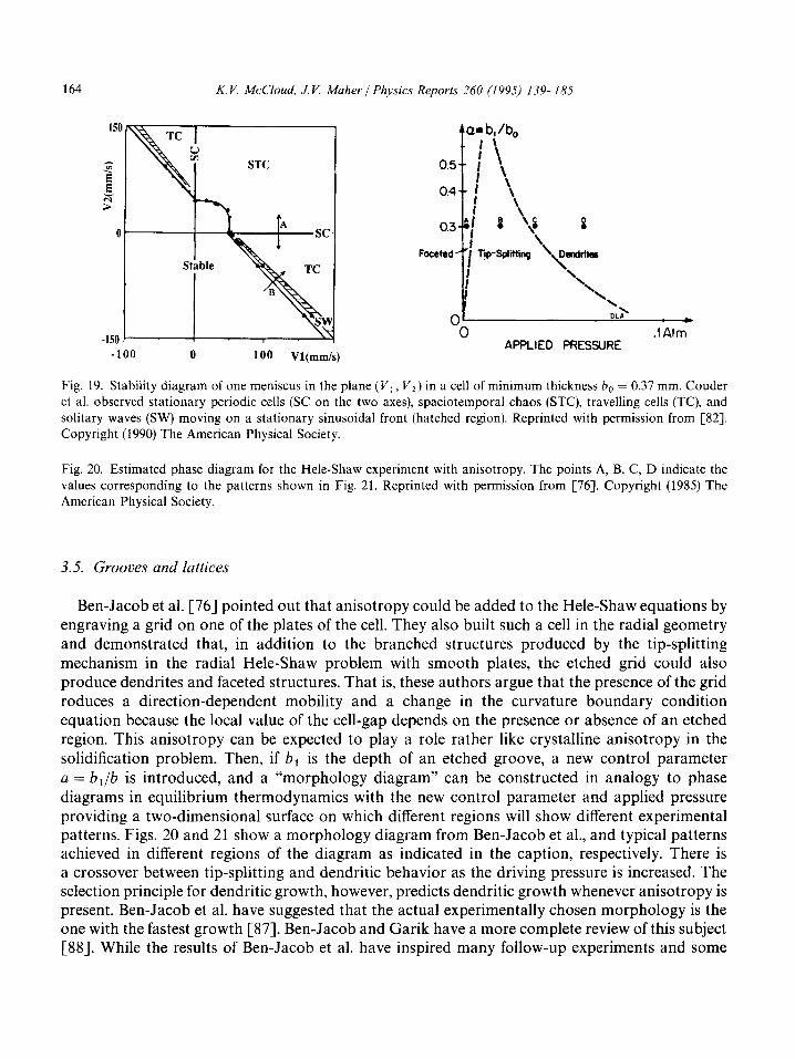
Fig. 19. Stability diagram of one meniscus in the plane (VI, V,) in a cell of minimum thickness b0 = 0.37 mm. Couder et al. observed stationary periodic cells (SC on the two axes), spaciotemporal chaos (STC), travelling cells (TC), and solitary waves (SW) moving on a stationary sinusoidal front (hatched region). Reprinted with permission from [82]. Copyright (1990) The American Physical Society.
Fig. 20. Estimated phase diagram for the Hele-Shaw experiment with anisotropy. The points A, B, C, D indicate the values corresponding to the patterns shown in Fig. 21. Reprinted with permission from [76]. Copyright (1985) The American Physical Society.
3.5. Grooves and lattices
Ben-Jacob et al. [76] pointed out that anisotropy could be added to the Hele-Shaw equations by engraving a grid on one of the plates of the cell. They also built such a cell in the radial geometry and demonstrated that, in addition to the branched structures produced by the tip-splitting mechanism in the radial Hele-Shaw problem with smooth plates, the etched grid could also produce dendrites and faceted structures. That is, these authors argue that the presence of the grid reduces a direction-dependent mobility and a change in the curvature boundary condition equation because the local value of the cell-gap depends on the presence or absence of an etched region. This anisotropy can be expected to play a role rather like crystalline anisotropy in the solidification problem. Then, if b, is the depth of an etched groove, a new control parameter a = bl/b is introduced, and a “morphology diagram” can be constructed in analogy to phase diagrams in equilibrium thermodynamics with the new control parameter and applied pressure providing a two-dimensional surface on which different regions will show different experimental patterns. Figs. 20 and 21 show a morphology diagram from Ben-Jacob et al., and typical patterns achieved in different regions of the diagram as indicated in the caption, respectively. There is a crossover between tip-splitting and dendritic behavior as the driving pressure is increased. The selection principle for dendritic growth, however, predicts dendritic growth whenever anisotropy is present. Ben-Jacob et al. have suggested that the actual experimentally chosen morphology is the one with the fastest growth [87]. Ben-Jacob and Garik have a more complete review of this subject [SS]. While the results of Ben-Jacob et al. have inspired many follow-up experiments and some

K.V. McCloud, J. V. Maher / Physics Reports 260 (1995) 139-185 165
(a)
(c)
0-d
Cd)
Fig. 21. The various patterns observed in the Hele-Shaw experiments with anisotropy. (a)-(d) correspond to points (A)-(D) in Fig. 20, respectively, and show (a) faceted growth, (b) tip-splitting, (c) needle crystals and (d) dendrites. The plate diameter is 25 cm. Reprinted with permission from [76]. Copyright (1985) The American Physical Society.
simpler experiments such as the gap-gradient experiments discussed above, it is very difficult to write down the boundary condition confidently. This leaves a greater gap between measurements and interpretation than in the case for many of the experiments discussed above. The greater variety of morphologies which can be attained and the clear resemblance of some of these patterns to patterns seen in more complicated growing systems (crystalline, biological and other systems of technological importance) give promise of additional insight despite the lack of unambiguous mathematical formulation, and as a result a wide range of variant experiments have by now been performed. In addition, theoretical work by Almgren et al. [89] has shown that radial fingering with anisotropic surface energy obeys different scaling laws than isotropic fingering; a result confirmed by simulations run by Almgren et al. [90] and preliminary experimental results from Ignes-Mull01 and Maher [91].
Chen and Wilkinson [92] and Chen [93] also ran a series of radial flow experiments over etched lattices, always at very high values of the asymmetry parameter, and they demonstrated a variety of highly branched structures whose symmetry depended on the symmetry of the etched lattice. In particular, regular lattices at high anisotropy [93] always gave patterns which resembled

166 K. V. McCloud, J. V. Maher / Physics Reports 260 (1995) 139-185
Fig. 22. Typical fingering patterns in an extremely anisotropic Hele-Shaw cell. The top time series involves miscible fingering, while the bottom involves immiscible fingering under the same conditions. Reprinted with permission from [93]. Copyright (1987) Springer-Verlag.
achievable crystal-growth patterns with faceting at sufficiently low driving rates and dendrites with the symmetry of the underlying lattice at higher driving rates. Randomly etched patterns on the cell face produced highly branched structures which lacked symmetry and generally resembled DLA [46] patterns. Examples of the range of patterns attainable under these conditions are shown in Fig. 22.
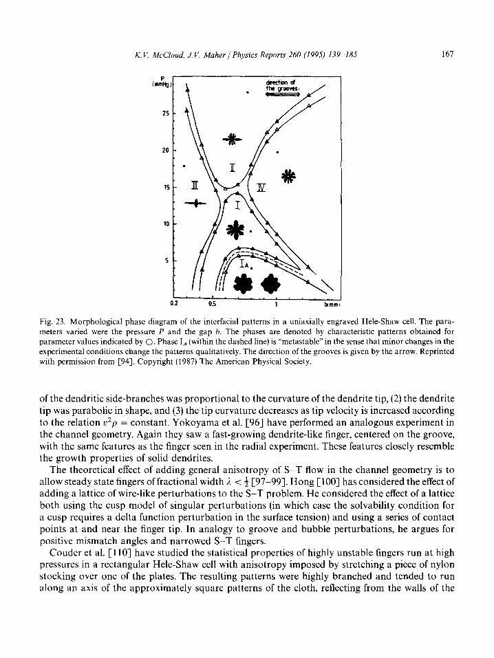
Horvath et al. [94] have tried to simplify the etched-lattice problem by replacing the lattice with a set of parallel grooves in radial flow. This produces a more complicated morphology diagram than that of Ben-Jacob et al., with faster growth in the direction of the grooves at sufficiently high values of the anisotropy parameter, n. The value of the anisotropy parameter needed to produce enhanced growth in the groove direction decreases with increasing values of the applied pressure. A morphology diagram of this system is shown in Fig. 23.
Matsushita and Yamada [95] constructed a radial cell with a single groove running from the center to the edge of the cell. This experiment demonstrated that patterns grown in such a cell looked like normal radial viscous fingering in all directions except that of the single groove. In the direction of the groove, the radial finger was converted into a much-faster-growing dendrite-like structure, much like that reported by Couder et al. [72] for a bubble driven in front of one finger in a radial viscous fingering pattern. Matsushita and Yamada further showed that (1) the wavelength
K. V. McCloud, J. V. Maher / Physics Reports 260 (1995) 139-185 167
0.2 05 1 bimml
Fig. 23. Morphological phase diagram of the interfacial patterns in a uniaxially engraved Hele-Shaw cell. The para- meters varied were the pressure P and the gap h. The phases are denoted by characteristic patterns obtained for parameter values indicated by 0. Phase IA (within the dashed line) is “metastable” in the sense that minor changes in the experimental conditions change the patterns qualitatively. The direction of the grooves is given by the arrow. Reprinted with permission from [94]. Copyright (1987) The American Physical Society.
of the dendritic side-branches was proportional to the curvature of the dendrite tip, (2) the dendrite tip was parabolic in shape, and (3) the tip curvature decreases as tip velocity is increased according to the relation v2p = constant. Yokoyama et al. [96] have performed an analogous experiment in the channel geometry. Again they saw a fast-growing dendrite-like finger, centered on the groove, with the same features as the finger seen in the radial experiment. These features closely resemble the growth properties of solid dendrites.
The theoretical effect of adding general anisotropy of S-T flow in the channel geometry is to allow steady state fingers of fractional width i < t [97-991. Hong [ 1001 has considered the effect of adding a lattice of wire-like perturbations to the S-T problem. He considered the effect of a lattice both using the cusp model of singular perturbations (in which case the solvability condition for a cusp requires a delta function perturbation in the surface tension) and using a series of contact points at and near the finger tip. In analogy to groove and bubble perturbations, he argues for positive mismatch angles and narrowed S-T fingers.
Couder et al. [ 1 lo] have studied the statistical properties of highly unstable fingers run at high pressures in a rectangular Hele-Shaw cell with anisotropy imposed by stretching a piece of nylon stocking over one of the plates. The resulting patterns were highly branched and tended to run along an axis of the approximately square patterns of the cloth, reflecting from the walls of the

168 K. V. McCloud, J. V. Maher / Physics Reports 260 (I 995) 139- I85
channel as these were encountered. The patterns had a resemblance to DLA [46] patterns in a channel, but when the authors averaged a large number of patterns, they discovered that there was a significant bias in favor of the pure S-T finger. That is, the authors discretized the interior of their experimental cell and constructed a probability of occupation for each location on the resulting lattice. The high probability locations on this lattice formed a single finger shape, and the set of locations with occupation probability 0.5 defined a S-T finger whose width was suggestively close to the width 3, = 0.5 which would be the expected width of a stable S-T finger at the same driving pressure in the absence of the perturbating cloth lattice. Arniodo et al. [40.44,110,111], as well as Brener et al. [ 1123 and Levine and Tu [ 1131 have taken this result further and investigated the statistical properties of highly driven, highly unstable viscous fingers in channel and wedge geometries without any further perturbations than the very small cell imperfections which caused the fingers to go unstable. As with the nylon stocking experiment, averaging very many realizations of the channel flow results in a probability distribution whose locations at which occupancy is more likely than 0.5 form a ST finger of channel width 0.5. Averages of computer-generated patterns are shown in Fig. 24, and a histogram showing the average occupancy of the experimental cells in unstable flows can be seen in Fig. 25. The authors’ DLA simulations produce a similar averaged pattern. Performing the same average on many realizations of wedge flow results in an average shape which closely resembles the limit width of stable fingers in the same wedge. These experiments strongly suggest that the S-T problem survives the imposition of at least some perturbations (viz., the anisotropy of the cloth and the poorly specified but very small “noise” produced by cell-imperfections which destabilize the S-T finger at very high driving pressures). Such survival is not at all obvious since perturbation can add crucially important terms to the dynamical equations governing growth. If an understanding can be reached of the conditions under which the S-T solution survives as the underlying pattern, even if only on a statistical basis, it would represent a significant step forward in understanding growth dynamics.
Brener et al. [112] have pursued the possible ST/DLA connection by taking the mean-field theory for DLA and inserting a finite probability threshold for growth, producing good agreement with the S-T finger shape. This also agrees well with simulations generated by Liang [4,114] who modified DLA with a finite-threshold-like requirement of multiple hits before a growth site could become occupied and added the possibility of particles leaving the cluster with a probability related to the local curvature. Brener et al. [112] argued that the Laplacian term in their DLA mean-field theory invites a singular perturbation from any surface tension analog, just as is the case for the ST problem. They added anisotropy to their model and found finger widths to increase with the strength of the anisotropy. Levine and Tu Cl131 have extended the theory to radial and sector geometries. In the sector geometry, their mean-field theory accurately describes the average DLA structures, and gives good agreement with the angular width of fingers formed in the sector geometry. Nittman and Stanley [115] have developed a noise-driven model to investigate the sidebranching of S-T fingers seen in most anisotropic S-T experiments. In this model the anisotropy is introduced through an underlying square lattice, and noise reduction is used to tune the effects of such parameters as concentration fluctuations.
More recently, Ben Amar et al. [116] have extended the earlier work of Couder et al. [l lo] with a nylon cloth stretched over one of the plates of a rectangular Hele-Shaw cell and oriented at 45” to the symmetry axis of the cell. By varying the dimensionless driving force, B, over a wide range, most of which corresponds to unstable fingers, and once again averaging over many flow realizations,
K. V. McCloud, J. V. Maher 1 Physics Reports 260 (1995) 139-185 169
d
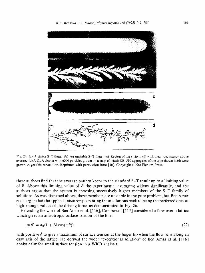
Fig. 24. (a) A stable ST finger. (b) An unstable ST finger. (c) Region of the strip in (d) with mean occupancy above average. (d) A DLA cluster with 6000 particles grown on a strip of width 128.510 aggregates of the type shown in (d) were grown to get this repartition. Reprinted with permission from [40]. Copyright (1990) Plenum Press.
these authors find that the average pattern keeps to the standard S-T result up to a limiting value of B. Above this limiting value of B the experimental averaging widens significantly, and the authors argue that the system is choosing successively higher members of the ST family of solutions. As was discussed above, these members are unstable in the pure problem, but Ben Amar et al. argue that the applied anisotropy can bring these solutions back to being the preferred-ones at high enough values of the driving force, as demonstrated in Fig. 26.
Extending the work of Ben Amar et al. [ 1161, Combescot [ 1171 considered a flow over a lattice which gives an anisotropic surface tension of the form
o(e) = Go(l + 26cos(mO)) (22)
with positive 6 to give a maximum of surface tension at the finger tip when the flow runs along an easy axis of the lattice. He derived the wider “exceptional solution” of Ben Amar et al. [116] analytically for small surface tension in a WKB analysis.

170 K. V. MeCloud, J. V. Maher / Physics Reports 260 (1995) 139-185
I , 0.8
A AA AA A aAA
A A AA A A A
AA
-w/2 0 X
w/2
Fig. 25. Histograms showing the mean occupancy across a section of the linear cell for 75 unstable S-T fingers, and N = 510 DLA clusters of mass M = 6000 grown in a strip W = 128 and its fit by r(x, JJ) = rmax cos2(~y/W) (scale on the left). Reprinted with permission from [40]. Copyright (1990) Plenum Press.
In addressing the problem of what conditions can allow the SST dynamical equation (i.e., the Laplace equation) to survive the imposition of perturbations, Sarkar and Jasnow [49] have speculated on conditions under which the mobility tensor would remain isotropic in at least a statistical sense. They argue that, if the length scale of spatial perturbations is small enough in comparison with all other length scales in the problem, it could be appropriate to coarse grain the problem, producing a mobility tensor in the Darcy flow (Eq. (2)) w ose symmetry would reflect the h symmetry of the underlying disturbance. In this case, either random spatial noise or a regular lattice with square or hexagonal symmetry would be expected to have an isotropic mobility tensor. With an isotropic mobility tensor, the dynamic equation would remain a Laplace equation, and the perturbation would affect the observed patterns only through the boundary conditions. Any other underlying lattice symmetry would produce an average mobility tensor which was anisotropic, producing a growth equation which was no longer Laplacian. Most of the existing experiments presented above involve high enough driving pressures to produce capillary lengths which are comparable to the length scales of the applied spatial perturbations, so it is not clear whether or not any good tests of the Sarkar-Jasnow conjecture have been made. Preliminary reports from McCloud and Maher [118] at low driving pressures with very finely etched lattices indicate departures from the ST width for both square and rectangular lattices. The departures are in the direction of fingers wider than the S-T solution, differing from the result of single wire studies discussed above. There are small differences between results from square and rectangular lattices and this may suggest support for the Sarkar-Jasnow [49] conjecture and for the results of Ben Amar et al. [116] and Combescot [117]. However, the clear existence of important effects for the square lattice indicates that the boundary conditions are being modified in some important way. Fig. 27 shows the ratio of perturbed to unperturbed S-T finger width, &/&, for flows over square

K. V. McCloud, J. V. Maher J Physics Reports 260 (1995) 139-185 171
_____.__.____ .._.._ ---
0.001 0.002 B 0.003
Fig. 26. The width 1 of the different solutions as a function of capillary number B, with anisotropy. The dash-dotted lines recall the standard solutions in the absence of anisotropy, 0 - the width of the experimental occupancy histograms; full lines: a guide to the eye for the numerical integration (the data are not shown for clarity); n - the second numerical integration; the bold line is the exceptional solution. Reprinted with permission from [116]. Copyright (1993) The American Physical Society.
and rectangular lattices at several orientations 0, of flow-channel direction to lattice symmetry axis and for a variety of flow conditions [ 1181.
3.6. Temporally varying cell-gaps
Following a discussion and preliminary measurement by Ben-Jacob et al. [76], La Roche et al. [119] have measured patterns in a hinged cell whose initially parallel plates are separated at a constant angular velocity during the experiment. These patterns are qualitatively similar to a statistical simulation of the Poisson equation generated through an extension of the DLA model. In this model, diffusive particles are generated from all points outside the aggregate, and the resulting patterns are very similar to those produced in the hinged cell experiment. Sonin and Bartolino [120] have also analyzed such patterns, in both isotropic (glycerin) and anisotropic (liquid crystal 5CB and 8CB, which are in the nematic and smectic A phases at room temperature, respectively) fluids. For very small lifting angles, Eq. (8) should still be valid, and there should be a critical velocity that must be exceeded for instabilities to form. Sonin and Bartolino have shown the existence of this critical velocity in all the fluids studied and its dependence on the initial gap, and have shown that the relationship between the critical wavelength and the velocity are in satisfactory agreement with Eq. (8), even for the liquid crystals. In addition, the effect of adding an external anisotropy to the lifting experiment using a grooved cell was studied, and the patterns formed by the liquid crystals was shown to be dependent on the orientation of the grooves, probably due to an interaction between the orientation of the grooves and the director of the liquid crystals.
3.7. Patterns driven into viscoelastic fluids
If the simple viscous fluid which is driven in all the experiments discussed above is replaced by a viscoelastic fluid, the problem becomes vastly richer and correspondingly less amenable to

172 K. V. A&Cloud, J. V. Maher / Physics Reports 260 (1995) 139-185
Rectangular Etching
1.3, T
I 1 I
0 2000 4000
l/B
Square Etching
0
n
@=O"
@=lO
0.9 +
0 2000 4000
IIB
Fig. 27. Ratio of wide fingers to normal S-T fingers vs the dimensionless parameter l/B for fingering over both square and rectangular lattices at the indicated flow-to-lattice orientation 0. Taken from [118].
analytic attack. A variety of experiments have elucidated possibilities for pattern formation in such complex fluids. These provide interesting hints for understanding the nonlinear steady state behavior of such fluids, for discerning relations between molecular structure of the complex fluids and their mechanical properties, and for identifying dynamical conditions needed to produce given types of pattern features. On the other hand, these experiments are much farther from quantitative understanding than most of the others discussed above, and their interpretation must rely on careful empirical work, much of which remains to be done.
Complex fluids generally show a variety of time scales and thus their response to imposition of a pressure gradient in a Hele-Shaw cell cannot be simply described with a mobility (viscosity) as in
K. V. McCloud, J. V. Maher / Physics Reports 260 (1995) 139-185 173
Eq. (4). Since Hele-Shaw experiments drive the interface far from equilibrium, it is not even clear that the linear viscoelastic parameters normally invoked to describe viscoelastic fluids are relevant to the dynamics of the air/complex fluid interface (although in the following discussion we will naively discuss possibilities of qualitatively understanding experiments through linear viscoelastic parameters). Since a viscoelastic fluid can generally be expected to act like an elastic solid when driven above some material-dependent frequency, normal stresses can be expected to be especially important at high driving rates, and this adds extra emphasis to the concerns discussed above about plate flexing [ 11,39,55,77] and its possible effect on the pattern formation process. With all these warnings, we will now proceed to survey the available results on this rich and fascinating subject.
3.7.1. Clays and solutions of single-chain homopolymers Nittman et al. [121,122] demonstrated that DLA-like patterns could be formed in a Hele-Shaw
cell when aqueous solutions of homopolymer (polysaccharides of high molecular weight) were driven by water in the radial geometry. With water driving into an aqueous solution, the effective dynamical interfacial tension, while not necessarily zero, is very low, and this allows pattern formation down to very short length scales. Low surface tension also occurs in some cases of viscous fingering between Newtonian fluids without exhibiting such highly ramified structures as seen by Nittmann et al. [121,122]. It seems likely that the shear-thinning property of the polymer solution contributed in an important way to the richness of the observed patterns. Daccord et al. [123] measured the shear-rate dependence of the viscosity of their polysaccharide solution, and indeed the viscosity was changing significantly over shear rates which were plausibly important in the problem. (An example of a pattern from [123] is shown in Fig. 28). The importance of the shear-thinning aspect of the fluids was confirmed in a later series of experiments involving both miscible and immiscible flow in a shear-thinning clay solution [124-1261.
Subsequent work showed that the ramified patterns observed by Nittmann et al. [121,122] could be observed in a number of polymer and clay solutions, in both the channel [123-1271 and radial [127-1311 geometries, and that the fractal dimensions of the patterns were in general compatible with regarding the patterns as DLA objects [123,124,127-130,132,133]. Van Damme has an extensive review article on fingering in such non-Newtonian and colloidal fluids and the fractal structures thus formed [77].
Zhao and Maher [134,135] injected dyed water into solutions of poly(oxyethylene) (PEO) in a radial Hele-Shaw cell and, by varying the molecular weight and solution concentration of reasonably monodisperse polymer samples, were able to show that the DLA-like objects were but one of a variety of patterns which driven homopolymer systems could exhibit. Fig. 29 shows a variety of patterns observed by Zhao and Maher from these homopolymer solutions. In addition, these experiments showed empirical evidence of regularity in the length scales of the patterns. That is, for all pattern morphologies shown in Fig, 29, the initial length scale at the onset of instability and the dominant wavelength in modal analysis of the well-developed patterns could be collapsed onto one roughly universal curve by regarding them as functions of a combination of the molecular weight M, polymer concentration, c, water injection rate Q, and the cell-gap b. This combination A = b2c2.2/QM3.4 is purely empirical but is close to the functional form one would expect for known polymer scaling rules [136] to give a Deborah number, the ratio of the imposed shear rate

174 K. V. McCloud, J. V. Maher / Physics Reports 260 (1995) 139-185
Fig. 28. Water displacing scleroglucan (a polysaccharide solution) (shear thinning) in the radial cell. Taken from [123]. Reprinted with permission of Kluwar Academic Publishers.
Fig. 29. Example of typical patterns formed by injecting water into solutions of monodisperse PEO in a radial
Hele-Shaw cell. For each row, the injection rate increases from low value on the left to high value on the right. The first two rows are for molecular weight 5000000 (concentrations are 0.3 wt% and 1.0 wt%, respectively). The last two rows are for molecular weight 300000 (concentrations 5 wt% and lOwt%, respectively). b = 0.4 mm for all cases except the first row where h = 0.8 mm. Reprinted with permission from [13.5]. Copyright (1993) The American Physical Society.
to the shear-thinning shear rate of the polymer solution. Length scales collapsed by using the parameter A are shown in Fig. 30 [134,135].
In a very suggestive and beautifully simple experiment, Smith et al. [137] have recently studied the effect on the S-T steady state finger of adding a very small amount of homopolymer to the driven fluid. At such dilute polymer concentrations, the patterns do not break up into highly ramified objects, but even concentrations as low as one part per million are sufficient to force a transition out of the S-T finger into a narrower finger, as shown in Fig. 31. The onset of this narrowing transition occurs near the point where the applied shear rate matches the inverse of the polymer’s Zimm relaxation time (a different Deborah number than the one discussed above is suggested here, but very much the same in spirit), and this onset is often initiated by small- amplitude oscillations.
3.7.2. Fracture in clays and in solutions of associating polymers While several of the patterns shown in Fig. 29 might appear at first glance to be fracture of
a solid-like viscoelastic solution, a close examination of the patterns shows that side-branches are always at relatively small angles to the main-trunk growth (50’ or less). In addition, examination of
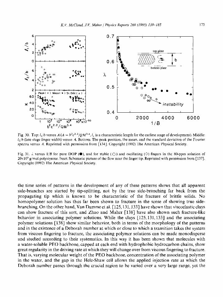
K. V. McCloud, J. V. Maher 1 Physics Reports 260 (I 995) 139-185 175
0.6
h
0.5
top plate
zi!zzB s
bottom plate
@8 aD% l . 00
l 0 0 0
O Oo 0 l *
O o&2_ instability
1 lo2 io4 106 ~o*xlo-~o b2C2.2/QM3.4 l/B
Fig. 30. Top: ii/b versus A (A = ~‘c’.‘/QM~.~, 1i is a characteristic length for the earliest stage of development). Middle: lz/b (late stage finger width) versus A. Bottom: The peak position, the mean, and the standard deviation of the Fourier spectra versus A. Reprinted with permission from [134]. Copyright (1992) The American Physical Society.
Fig. 31. i versus l/B for pure DOP (O), and for stable (0) and oscillating (0) fingers in the 80-ppm solution of 20~10~ g/mol polystyrene. Inset: Schematic picture of the flow near the finger tip. Reprinted with permission from [ 1371. Copyright (1992) The American Physical Society.
the time series of patterns in the development of any of these patterns shows that all apparent side-branches are started by tip-splitting, not by the true side-branching far back from the propagating tip which is known to be characteristic of the fracture of brittle solids. No homopolymer solution has thus far been shown to fracture in the sense of showing true side- branching. On the other hand, Van Damme et al. [125,131,133] have shown that viscoelastic clays can show fracture of this sort, and Zhao and Maher [138] have also shown such fracture-like behavior in associating polymer solutions. While the clays [125,131,133] and the associating polymer solutions [138] show similar behavior, both in terms of the morphology of the patterns and in the existence of a Deborah number at which or close to which a transition takes the system from viscous fingering to fracture, the associating polymer solutions can be made monodisperse and studied according to their systematics. In this way it has been shown that molecules with a water-soluble PEO backbone, capped at each end with hydrophobic hydrocarbon chains, show great regularity in the driving rate at which they will change over from viscous fingering to fracture. That is, varying molecular weight of the PEO backbone, concentration of the associating polymer in the water, and the gap in the Hele-Shaw cell allows the applied injection rate at which the Deborah number passes through the crucial region to be varied over a very large range, yet the

176 K. V. MeCloud, J. V. Maher / Physics Reports 260 (I 995) 139-185
(4
Fig. 32. Four typical patterns of a 2.5% solution of hexadecyl-endcapped polymer of molecular weight 50700 at injection rates: (a) Q = l.Oml/min; (b) Q = 1.0 ml/min; (c) Q = 5.0 ml/min; and (d) Q = 2.0ml/min. The crossover from
viscous-fingering pattern to “fracturing” pattern is seen in (a) and (b). Reprinted with permission from [138]. Copyright (1993) The American Physical Society.
transition is always close to the same Deborah number. Examples of patterns below and above the fracture injection rate for one of these solutions are shown in Fig. 32. There is also a narrow range of injection rates over which either viscous fingering or fracture-like behavior may be seen in a given realization, suggesting that the transition may be supercritical. Changing the architecture of the associating polymer changes the Deborah number for the transition (e.g., changing the PEO with hydrocarbon endcaps to PEO with hydrocarbon comb-like teeth lowers the transition Deborah number by a factor of approximately 30), but fracture-like behavior always seems to be possible as long as associating groups are present on the polymer molecule and the polymer concentration is not too low. Attempts to force solutions of PEO without associating groups to exhibit fracture-like behavior have failed, even when the Deborah number is set a factor of 10 000 higher than that needed to make the solution of endcapped molecules fracture.
It has not as yet been possible to determine the physical property(s) of associating polymers and clays which allow them to show fracture-like behavior. While there is reason to worry about uncontrolled normal stresses causing plate flexing [77], with the resulting uncontrolled gap- gradients producing exotic and unintended local perturbations, several consistency checks have suggested that this is not a problem with the associating polymer solutions (run between thick glass plates of small radial extent and with close pressure monitoring), and there is no compelling reason to believe that it is a problem with the clays either. Further work is needed to elucidate the role of normal stresses if these systems are to be provided with a set of plausible dynamical equations. In the meantime, the experiments’ empirical regularities suggest interesting relations between the architecture of dissolved macromolecules and the dynamics of their solutions, relations which may eventually be understandable in terms of polymer scaling rules and which may also be important for the technology of liquid phase processing of such polymers.

K. V. McCloud, J. V. Maher / Physics Reports 260 (1995) 139-185 177
3.7.3. Patterns in foams and gels Park and Durian [ 1391 have measured radial viscous fingering of air driven into a Hele-Shaw
cell filled with commercial shaving foam. Under most conditions the foam flowed like a plug, leaving no thick film behind. They observed an onset unstable wavelength which can be collapsed for many flow conditions under the assumption that the flow is two-dimensional whenever a characteristic foam-bubble diameter is comparable in size to the cell-gap. At high shear rates, S-T-like viscous fingering was observed while jagged, torn patterns appeared at low shear rates. These two types of patterns can be seen in Fig. 33. Attempts to relate the crossover between jagged and S-T patterns to plausible time scales for foam relaxation had limited success.
Bhaskar et al. Cl403 have related the penetration of gastric mucin networks lining the stomach wall by HCl to the viscous fingering problem with an analysis which is essentially the S-T analysis even though the physical problem is not closely related to Hele-Shaw experiments. Stanley has reviewed this biomedical viscous fingering work [141].
3.7.4. Patterns in liquid crystals A wide variety of viscous fingering experiments have been performed with liquid crystals, most of
which have been discussed in the extensive review articles of Lam [142] and Sonin [S]. In the only experiment in the channel geometry, Yang et al. Cl433 have concentrated on highly driven flows, observing a rich variety of morphologies reminiscent of that discussed above for high anisotropy fingering over a lattice. Examples of such patterns are shown in Fig. 34. Similarly, radial flows with liquid crystals can produce a rich variety of patterns analogous to those seen in flow over a lattice, with the liquid crystal phase providing the crucial anisotropy and uncertainty in writing the dynamic boundary condition providing the limit to quantitative analysis [35,36,144-1471. There are four basic pattern types: (1) tip-splitting branches (similar to those seen in isotropic fluids); (2)
6 5
0 0
-6 -5
1 (a)?= 23 s.' (b) 1; = 0.95 s.’
112 -6 0 6 12 ‘110 -5 0 5 10
Fig. 33. Pattern formation in cm for foam displacement at high (a) and low (b) shear strain rates. For (a), the time interval between traces is At = (1/6Os), the plate separation is b = 0.104 cm, the driving pressure is P = 10 kPa, and the sample radius is R = 13.6 cm. For (b), At = 0.5 s, b = O.O34cm, P = 6 kPa and R = 13.0cm. Reprinted with permission from [ 1391. Copyright (1994) The American Physical Society.

178 K. V. McCloud, J.V. Maher 1 Physics Reports 260 11995) 139-185
:
(a)
Cd)
(b
-
(e) (1)
Fig. 34. Evolution of finger when P = 0.8cm Hg, b = 0.3 mm. (a) Single finger. (b) Hump. (c), (d) Side-wrinkling.
(e) Tip-splitting. (f) Side-branching. Reprinted with permission from [143]. Copyright (1989) Springer-Verlag.
dense branching (dense space-filling patterns with unstable tips); (3) sparse dendritic (less dense, with stable tips and short side branches at approximately 60” to the direction of the fingers); and (4) dense dendritic (stable tips, sidebranches of different length and angles). Some of these differing patterns are shown in Fig. 35. An example of a liquid crystal exhibiting these behaviors is that of the liquid crystal 8CB [146] which has the phase sequence (when cooled) of isotropic liquid to nematic to smectic A. 8CB shows all of the above types of patterns, depending on the driving pressure and the temperature (which controls the liquid crystalline phase). A morphology diagram for 8CB is shown in Fig. 36. In the isotropic phase, the only pattern formed is dense-branching. In the nematic phase, the pattern is dense-branching, going to sparse dendritic for some values of the

K. V. McCloud, J. V. Maher / Physics Reports 260 (1995) 139-185 179
(a) (b)
Fig. 35. Main morphological types of the air viscous fingers in liquid crystals: (a) dense branching (DB); (b) sparse
dendritic (SD); (c) dense dendritic (DD) Reprinted with permission from [146]. Copyright (1988) Les Editions de Physique.
Fig. 36. Morphological pressure-temperature phase diagram for the radial air viscous-finger patterns in 8CB. Reprinted with permission from [146]. Copyright (1988) Les Editions de Physique.
driving pressure as the temperature is lowered. The disappearance of the sparse dendritic regime may be due to smectic fluctuations in the liquid crystal destroying the flow alignment [35]. This explanation is borne out by a study of the liquid crystal 7CB, which has no smectic phase, and shows sparse dendritic behavior until solidification [146]. In the smectic A phase for 8CB, the
180 K. V. McCloud, J. V. Maher / Physics Reports 260 (1995) 139-185
patterns are dense-branching at low pressures, going to dense dendritic at higher pressures. Some patterns were not distinctly of any one morphology, and these areas were left blank in the morphology diagram.
In general, the patterns formed in smectic A liquid crystals are dependent on the initial orientation of the director. If the director is initially prependicular to the cell walls, the pattern formed is independent of the direction of the air flow. However, if the director is initially planar (lies in the plane of the cell and in a single direction), then the patterns are strongly dependent on the direction of the air flow. For low driving pressure, the fluid will flow in the direction parallel to the smectic layers (perpendicular to the director). For higher driving pressure, the fluid will flow both parallel to and perpendicular to the director. For even higher pressures, the fluid flow is perpen- dicular to that of the layers. Possibly the smectic layers are being destroyed in this case.
Ferroelectric smectics have a macroscopic polarization due to their characteristic helical struc- ture, as well as to ordered layers (like the smectic A). The typical radial patterns turn out to be tip-splitting branching [5,150,151]. The normalized local pyrocoefficient y in these patterns has been investigated, and shows that: (1) the director orientation near the finger tip is more uniform than in the bulk; (2) there is a change in the direction of the electrical polarization near the borders of the fingers; and (3) the air viscous fingers are also electrically active, due probably to a wetting layer of the liquid crystal left behind in the flow. These wetting layers are extremely nonuniform.
Zheng et al. [148] have observed the effect of adding parallel grooves to radial fingering through nematic MBBA. The extrinsic anisotropy of the grooves plus the intrinsic anisotropy of the liquid crystal produce a dendritic pattern, not seen in the experiment with an isotropic fluid in a cell with parallel grooves [145], although dendritic growth has been observed with an isotropic liquid in a cell with a single groove [95,96]. Lam et al. [149] have done a similar experiment involving fingering through nematic MBBA in a cell with concentric grooves engraved on the plate. They see simple fingers and tip-split fingers coexisting with dendritic fingers. If the gap is made smaller, the fingers narrow.
Quantitative results have been obtained and verified experimentally for the onset-wavelength of fingering in liquid crystals. There is an interaction between the separate fingers in a liquid crystal pattern not seen in normal fluids, due to the elongated forms of the liquid crystals and the specific character of the intermolecular forces. Buka and Palffy-Muhoray 135,361 have done a stability analysis for the dense-branching morphology, and found that the wave number of the fastest growing mode is given by
m* = 1 V’oRI~ - 1) + 1 [( I’* 3 In RoJR >I (23)
based on the assumption that the pattern is a circle of radius R, on which there exist (large) perturbations [SO], with a cell radius of radius Ro. They obtained a relation between the pressure and the critical wavelength W, which depends on the radius of the pattern circle as [146]
P = 12n* (24)
Fluid flow in the isotropic phase of 8CB agree well with the prediction P cc Wi3, as shown in Fig. 37 [146]. In the nematic and smectic A phases, which do not show dense-branching

K. V. McCloud, J. V. Maher / Physics Reports 260 (199s) 139-185 181
lo-
8-
6 6-
4
a 4-
0 400 600 1200 1600 2000 2400
(R&J3
Fig. 37. Graph illustrating the relation between applied pressure P, and the critical wavelength W, for onset of instability as air displaces the liquid crystal 8CB in its isotropic phase. T = 41S”C. The solid line is the best fit. Reprinted with
permission from [146]. Copyright (1988) Les Editions de Physique.
morphology, the critical wavelength depends dramatically on the temperature. The critical wavelength in the ferroelectric smectic C* phase has also been investigated [151], and shows a dependence on the thickness of the cell stronger than that predicted by the usual stability analysis. The critical wavelength decreases with the thickness.
6. Conclusions
The extensive work on experimental perturbations to Saffman-Taylor flow is difficult to organize since the available experiments are related mainly by the hope of a research community that the S-T problem provides a framework on which progress can be made in understanding a wide variety of dynamical problems. These dynamical problems add richness and beauty of our visual world, but they also build processing-history inhomogeneities into samples of materials which would be more useful if they could be made more homogeneous.
Despite the diversity of the set of experiments presented above, several useful generalizations can be stated here: (1) Much mathematical progress has been made on understanding the simplest of these experiments. (2) Even where experiment and theory cannot yet make contact, most experi- ments exhibit fascinating regularities, and frequently these regularities point to empirical scaling laws. (3) Many of the results discussed above emanate from survey experiments whose wide- ranging, if qualitative, results can very usefully be deepened by new generations of careful experiments.
Acknowledgements
The authors are most grateful to J. Casademunt, D. Jasnow, A. Karma, W. van Saarloos, H.E. Stanley, and C. Yeung for helpful discussions.
182 K. V. McCloud, J. V. Maher / Physics Reports 260 (1995) 139-185
References
[l] P.G. Saffman and G.I. Taylor, Proc. R. Sot. Lond. A 245 (1958) 312. [2] S. Hill, Chem. Eng. Sci. 1 (1952) 247. [S] G. Homsy, Ann. Rev. Fluid Mech. 19 (1987) 271.
[4] D. Bensimon, L.P. Kadanoff, S. Liang, B.I. Shraiman and C. Tang, Rev. Mod. Phys. 58 (1986) 977. [S] A.A. Sonin, Rivista de1 Nuovo Cimento 14 (1991) 1. [6] Y. Couder, in: Chaos, Order, and Patterns, eds. R. Artuso, P. Cvitanovibc and G. Casati (Plenum Press in
cooperation with NATO Scientific Affairs Division, New York, 1991). [7] P.G. Saffman, IMA J. Appl. Math. 46 (1991) 137. [S] H.J.S. Hele-Shaw, Nature 58 (1898) 34.
[9] C. Park and G.M. Homsy, J. Fluid Mech. 139 (1984) 291.
[lo] P. Tabeling and A. Libchaber, Phys. Rev. A 33 (1986) 794. [l l] P. Tabeling, G. Zocchi and A. Libchaber, J. Fluid Mech. 177 (1987) 67.
[12] R. Chuoke, P. van Meurs and C. van der Poel, Trans. AIME 216 (1959) 189. [13] I. White, P.M. Colombera and J.R. Philip, Soil Sci. Sot. Am. 41 (1976) 483.
[14] C.W. Park, S. Gore11 and G.M. Homsy, J. Fluid Mech. 141 (1984) 257. [15] M.W. DiFrancesco and J.V. Maher, Phys. Rev. A 40 (1989) 295. [16] M.W. DiFrancesco and J.V. Maher, Phys. Rev. A 39 (1989) 4709. [17] H. Zhao and J.V. Maher, Phys. Rev. A 42 (1990) 5894.
[18] E. Pitts, J. Fluid Mech. 97 (1980) 53. [19] P.G. Saffman, J. Fluid Mech. 173 (1986) 73.
[20] J.W. McLean and P.G. Saffman, J. Saffman, J. Fluid Mech. 102 (1981) 455. [21] J.M. Vanden Broeck, Phys. Fluids. 26 (1983) 2033.
J.W. McLean and P.G. Saffman, J. Fluid Mech. 102 (1981) 455.
[22] D.A. Kessler and H. Levine, Phys. Rev. A 33 (1986) 2621, 2634. [23] R. Combescot. T. Dombre, V. Hakim, Y. Pomeau and A. Pumir, Phys. Rev. Lett. 56 (1986) 2036.
[24] B.I. Shraiman, Phys. Rev. Lett. 56 (1986) 2028. [25] DC. Hong and J. Langer, Phys. Rev. Lett. 56 (1986) 2032.
[26] D. Bensimon, Phys. Rev. A 33 (1986) 1302. [27] S. Sarkar and D. Jasnow, Phys. Rev. A 35 (1987) 4900. [28] G. Tryggvason and H. Aref, J. Fluid Mech. 136 (1983) 1. [29] G. Tryggvason and H. Aref, J. Fluid Mech. 154 (1985) 287. [30] J. Casademunt and D. Jasnow, Phys. Rev. Lett. 67 (1991) 3677.
[31] J.V. Maher, Phys. Rev. Lett. 54 (1985) 1498.
[32] S. Curtis and J. Maher, Phys. Rev. Lett. 63 (1989) 2729. [33] D.A. Kessler and H. Levine, Phys. Rev. A 33 (1986) 3625.
[34] L. Paterson, J. Fluid Mech. 113 (1981) 513. [35] A. Buka and P. Palffy-Muhoray, Phys. Rev. A 36 (1987) 1527.
[36] A. Buka, P. Palffry-Muhoray and Z. R&z, Phys. Rev. A 36 (1987) 3984. [37] J. Ortin and J. Ignes-Mullol, private communication.
[38] S.N. Rauseo, P.D. Barnes and J.V. Maher, Phys. Rev. A 35 (1987) 1245. [39] H. Thome, M. Rabaud, V. Hakim and Y. Couder, Phys. Fluids A 2 (1989) 224. [40] A. Arneodo, Y. Couder, G. Grasseau, V. Hakim and M. Rabaud, in: Nonlinear Evolution of Spacio-temporal
Structures in Dissipative Continuous Systems, eds. F.H. Busse and L. Kramer (Plenum, New York, 1990). [41] M. Ben Amar, V. Hakim, M. Mashaal and Y. Couder, Phys. Fluids A 7 (1990) 161. [42] M. Ben Amar, Phys. Rev. A 44 (1991) 3673. [43] R. Combescot and M. Ben Amar, Phys. Rev. Lett. 67 (1991) 453. [44] A. Arneodo, Y. Couder, G. Grasseau, V. Hakim and M. Rabaud, Phys. Rev. Lett. 63 (1989) 984. [45] E. Brener, D. Kessler, H. Levine and W. Rappel, Europhysics Lett. 13 (1990) 161. [46] T.A. Witten and L.M. Sander, Phys. Rev. Lett. 47 (1981) 1400.

K. V. McCloud, J. V. Maher 1 Physics Reports 260 (1995) 139-185 183
[47] L.P. Kadanoff, J. Stat. Mech. 39 (1985) 267. [48] L. Sander, P. Ramanlal and E. Ben-Jacob, Phys. Rev. A 32 (1985) 3160.
[49] S.K. Sarkar and D. Jasnow, Phys. Rev. A 39 (1989) 5299. [SO] E. Ben-Jacob, G. Deutscher, P. Garik, N. Goldenfeld and Y. Lareah, Phys. Rev. Lett. 57 (1986) 1903.
[Sl] E. Ben-Jacob, P. Garik and D. Grier, Superlattices Microstruct. 3 (1987) 599.
[52] J. Jasnow and C. Yeung, Phys. Rev. E 47 (1993) 1087. [53] Y. Couder, in: Random Fluctuations and Pattern Growth, eds. H.E. Stanley and N. Ostrowsky (Kluwer
Academic, Dordrecht, 1988).
[54] J.D. Chen, J. Fluid Mech. 201 (1988) 223.
[55] S.E. May and J.V. Maher, Phys. Rev. A 40 (1989) 1723.
[56] C. Yeung and D. Jasnow, Phys. Rev. A 41 (1990) 891.
[57] J. Sherwood and J. Nittmann, J. Phys. (Paris) 47 (1986) 15. [58] J. Nittmann, in: The Physics of Structure Formation: Theory and Simulation, eds. W. Giittinger and
G. Dangelmayr (Springer, New York, 1987).
[59] M.J. King and H. Sher, Phys. Rev. A 35 (1987) 929. [60] P.R. King, Phys. Rev. A 20 (1987) L529.
[61] M. Blunt and P.R. King, Phys. Rev. A 37 (1988) 3935.
[62] J. Lee, A. Coniglio and H. Stanley, Phys. Rev. A 41 (1990) 4589.
[63] G. Zocchi, B. Shaw, A. Libchaber and L. Kadanoff, Phys. Rev. A 36 (1987) 1894.
[64] D.C. Hong and J.S. Langer, Phys. Rev. A 36 (1987) 2325. [65] D.C. Hong, Phys. Rev. A 37 (1988) 2724.
[66] D.C. Hong, Phys. Rev. A 39 (1989) 2042.
[67] B.E. Shaw, Phys. Rev. A 40 (1989) 5875.
[68] H. Guo and D. Hong, Phys. Rev. A 41 (1990) 2995.
[69] M. Rabaud, Y. Couder and N. Gerard, Phys. Rev. A 37 (1988) 935. [70] E. Brener, H. Levine and Y. Tu, Phys. Fluids A 3 (1991) 529. [71] E. Brener, M. Rabaud and H. Thome, Phys. Rev. E 48 (1993) 1066.
[72] Y. Couder, 0. Cardoso, D. Dupuy, P. Tavernier and W. Thorn, Europhys. Lett. 2 (1986) 437. [73] Y. Couder, N. Gerard and M. Rabaud, Phys. Rev. A 34 (1986) 5175.
[74] R. Combescot and T. Dombre, Phys. Rev. A 39 (1989) 3525.
[75] H. Thome, R. Combescot and Y. Couder, Phys. Rev. A 41 (1990) 5739. [76] E. Ben-Jacob, R. Godbey, N. Goldenfeld, J. Koplik, H. Levine, T. Mueller and L.M. Sander, Phys. Rev. Lett. 55
(1985) 1315.
[77] H. Van Damme, in: Fractals and the Chemistry of Disordered Systems, Polymers, Colloids, and Slurries, ed. I. Avnir (Wiley, New York, 1988).
[78] H. Zhao, J. Casademunt, C. Yeung and J. Maher, Phys. Rev. A 45 (1992) 2455. [79] M.D. Savage, J. Fluid Mech. 80 (1977) 743. [80] M.D. Savage, J. Fluid Mech. 80 (1977) 757. [81] Y. Couder, S. Michalland, M. Rabaud and II. Thome, in: Nonlinear evolution of Spacio-temporal Structures in
Dissipative Continuous Systems, eds. F.H. Busse and L. Kramer (Plenum, New York, 1990).
[82] M. Rabaud, S. Michalland and Y. Couder, Phys. Rev. Lett. 64 (1990) 184. [83] M. Rabaud, Y. Couder and S. Michalland, Eur. J. Mech./Fluids 10 (1991) 253. [84] S. Michalland and M. Rabaud, Physica D 61 (1992) 197.
[SS] S. Michalland, M. Rabaud and Y. Couder, Europhys. Lett. 22 (1993) 17. [86] L. Pan and J. de Bruyn, Phys. Rev. Lett. 70 (1993) 1791. [87] E. Ben-Jacob, P. Garik, T. Mueller and D. Grier, Phys. Rev. A 38 (1988) 1370. [88] E. Ben-Jacob and P. Garik, Nature 343 (1990) 523. [89] R. Almgren, W. Dai and V. Hakim, Phys. Rev. Lett. 71 (1993) 3461. [90] R. Almgren, private communication. [91] J. Ignes-Mull01 and J.V. Maher, private communication. [92] J.D. Chen and D. Wilkinson, Phys. Rev. Lett. 55 (1985) 1892.
184 K. V. McCloud, J. V. Maher / Physics Reports 260 (1995) 139- 185
[93] J.D. Chen, Experiments in Fluids 5 (1987) 363. [94] V. Horvath, T. Vicsek and J. Kertesz, Phys. Rev. A 35 (1987) 2353.
[953 M. Matsushita and H. Yamada, J. Crystal Growth 99 (1990) 161.
[96] J. Yokoyama, Y. Kitagawa, H. Yamada and M. Matsushita, Physica A 204 (1994) 789.
[97] A.T. Dorsey and 0. Martin, Phys. Rev. A 35 (1987) 3989.
[98] G. Li, D.A. Kessler and L. Sander, Phys. Rev. A 34 (1986) 3535.
[99] D.A. Kessler, J. Koplik and H. Levine, Phys. Rev. A 34 (1986) 4980. [loo] D.C. Hong, Phys. Rev. A 43 (1991) 5199.
[loll J.R.A. Pearson, J. Fluid Mech. 7 (1959) 481. [ 1021 V. Hakim, M. Rabaud, H. Thome and Y. Couder, in: New Trends in Nonlinear Dynamics and Pattern Forming
Phenomena: The Geometry of Nonequilibrium (Plenum, New York, 1990).
[103] L. Fourtune, W. Rappel and M. Rabaud, Phys. Rev. E 49 (1994) R3576.
[104] E. Pitts and J. Greiller, J. Fluid Mech. 11 (1961) 3. Cl051 C.C. Mill and G.R. South, J. Fluid Mech. 28 (1967) 523.
[106] M.D. Savage, J. Fluid Mech. 80 (1982) 743.
[107] K.J. Ruschak, Ann. Rev. Fluid Mech. 17 (1985) 65.
[108] D.J. Coyle, C.W. Macosko and L.E. Striven, J. Fluid Mech. 216 (1990) 437.
[109] M. Deere, E. Gailly, J. Buchlin and M. Rabaud, preprint.
[l lo] Y. Couder, F. Argoul, A. Arneodo, J. Maurer and M. Rabaud, Phys. Rev. A 42 (1990) 3499.
[111] A. Arneodo, A. Argoul, Y. Couder and M. Rabaud, Phys. Rev. Lett. 66 (1991) 2332.
[112] E. Brener, H. Levine and Y. Tu, Phys. Rev. Lett. 66 (1991) 1978. [ 1131 H. Levine and Y. Tu, Phys. Rev. A 45 (1992) 1053. [114] S. Liang, Phys. Rev. A 33 (1986) 2663.
[115] J. Nittmann and H.E. Stanley, J. Phys. A: Math. Gen. 20 (1987) L981.
[116] M. Ben Amar, R. Combescot and Y. Couder, Phys. Rev. Lett. 70 (1993) 3047.
[I 171 R. Combescot, Phys. Rev. E 49 (1994) 4172. [ 1181 K.V. McCloud and J.V. Maher, preprint.
[119] H. La Roche, J.F. Fernandez, M. Octavia, A.G. Loeser and C.J. Lobb, Phys. Rev. A 44 (1991) R6185.
[120] A.A. Sonin and R. Bartolino, Nuovo Cimento 15D (1993) 1.
[121] J. Nittmann, Nature 314 (1985) 141.
[I223 G. Daccord, J. Nittmann and H. Stanley, in: Springer Proceedings in Physics 5: Physics of Finely Divided Matter, eds. N. Boccara and M. Daoud (Springer, New York, 1985).
[ 1231 G. Daccord, J. Nittmann and H. Stanley, in: On Growth and Form: Fractal and Non-Fractal Patterns in Physics, eds. H.E. Stanley and N. Ostrowsky (M. Nijhoff, Boston, 1986).
[124] H. Van Damme, C. Laroche and L. Gatineau, Rev. Phys. Appl. 22 (1987) 241. 11251 H. Van Damme, C. Laroche and P. Levitz, J. Phys. (Paris) 48 (1987) 1221. [126] H. Van Damme, E. Alsac, C. Laroche and L. Gatineau, Europhys. Lett. 5 (1988) 25. [127] J. Nittmann, Physica A 140 (1986) 124. [128] J. Nittmann, G. Daccord and H. Stanley, in: Fractals in Physics, eds. L. Pietronero and E. Tosatti (North-Holland,
New York, 1986). [129] G. Daccord, J. Nittmann and H.E. Stanley, Phys. Rev. Lett. 56 (1986) 336.
[130] H. Van Damme, F. Obrecht, P. Levitz, L. Gatineau and C. Laroche, Nature 320 (1986) 731. [131] E. Lemaire, P. Levitz, G. Daccord and H. Van Damme, Phys. Rev. Lett. 67 (1991) 2009. [ 1321 van Damme, in: The Fractal Approach to Heterogeneous Chemistry - Surface, Colloids, Polymers, ed. D. Avnir
(Wiley, New York, 1989). [ 1331 H. van Damme and E. Lemaire, in: Disorder and Fracture, eds. J.C. Charmet, S. Roux and E. Guyon (Plenum,
New York, 1990). Cl347 H. Zhao and J.V. Maher, Phys. Rev. A 45 (1992) R8328. [135] J.V. Maher and H. Zhao, in: Growth Patterns in Physical Sciences and Biology, eds. J.M. Garcia-Ruiz et al.
(Plenum, New York, 1993). [136] P.G. de Gennes, Europhys. Lett. 3 (1987) 195.

K. V. McCloud, J. V. Maher / Physics Reports 260 (I 995) 139-I 85 185
[137] D.E. Smith, X.Z. Wu, A. Libchaber, E. Moses and T. Witten, Phys. Rev. A 45 (1992) R2165. [ 1381 H. Zhao and J.V. Maher, Phys. Rev. E 47 (1993) 4278. [139] S. Park and D. Durian, Phys. Rev. Lett. 72 (1994) 3347. [140] K.R. Bhaskar, P. Garik, B.S. Turner, J.D. Bradley, R. Bansil, H.E. Stanley and J.T. LaMont, Nature 360 (1992)
458.
[141] H.E. Stanley, preprint. [142] L. Lam, H. Morris, R. Shaos, S. Yang, Z. Liang, S. Zheng and H. Liu, Liquid Crystals 5 (1989) 1813. [143] S.L. Yang, Z.C. Liang, R.F. Shao and L. Lam, in: Wave Phenomena: Theoretical, Computational, and Practical
Aspects: Proceedings of the First Woodward Conference, San Jose State University, 223 June 1988, eds. L. Lam and H.C. Morris (Springer, New York, 1989).
[144] A. Buka, J. Kertesz and T. Vicsek, Nature 323 (1986) 424.
[145] V.K. Horvath, J. Kertesz and T. Vicsek, Europhys. Lett. 4 (1987) 1133. [146] A. Buka and P. Palffy-Muhoray, J. Phys. (Paris) 49 (1988) 1319. Cl473 A. Buka, Physica Scripta T25 (1989) 114. [148] S. Zheng, R.F. Shao, L. Lam and Z.M. Sun, paper presented at the Centenary Conference in Liquid Crystal
Discovery, Beijing, 27 June-l July, 1988, and at the 12th International Liquid Crystal Conference, Freiburg, 15-19 August, 1988.
[149] L. Lam, in: Wave Phenomena: theoretical, computational, and practical aspects: Proceedings of the first Woodward Conference, San Jose State University, 2-3 June 1988, eds. L. Lam and H.C. Morris (Springer, New York, 1989).
[150] L.M. Blinov, D.Z. Radzhabov, A.A. Sonin and S.S. Yakovenko, Pis’ma Zh. Tekn. Fiz. 16 (1990) 36. [151] L.M. Blinov, D.Z. Radzhabov, A.A. Sonin and S.S. Yakovenko, preprint. [ 1521 K.V. McCloud and J.V. Maher, private communication.