Experimental Investigations on Shape Memory Alloy...
8
6 th International Conference on Advances in Experimental Structural Engineering 11 th International Workshop on Advanced Smart Materials and Smart Structures Technology August 1-2, 2015, University of Illinois, Urbana-Champaign, United States Experimental Investigations on Shape Memory Alloy Fiber Reinforced Concrete E. Khakimova 1 , M.M. Sherif 2 , O.E. Ozbulut 3 , D.K. Harris 4 , H.C. Ozyildirim 5 1 Graduate Research Assistant, Dept. of Civil and Environmental Engineering, University of Virginia, Charlottesville, United States. E-mail: [email protected] 2 Graduate Research Assistant, Dept. of Civil and Environmental Engineering, University of Virginia, Charlottesville, United States. E-mail: [email protected] 3 Assistant Professor, Dept. of Civil and Environmental Engineering, University of Virginia, Charlottesville, United States. E-mail: [email protected] 4 Assistant Professor, Dept. of Civil and Environmental Engineering, University of Virginia, Charlottesville, United States. E-mail: [email protected] 5 Research Scientist, Virginia Center for Transportation Innovation and Research, Charlottesville, United States. E-mail: [email protected] ABSTRACT Durability of concrete highly depends on its strength and resistance to cracking. Steel fibers improve the toughness of concrete and help control crack propagation. Plastic deformations of steel fibers provide significant energy dissipation. Strain hardening behaviour of steel fiber reinforced concrete mixtures leads to tighter cracks, which inhibits the penetration of harmful solutions into the concrete. However, steel fibers experience permanent deformations upon yielding and cannot provide self-centering and crack-closing properties. In this study, the use of randomly distributed shape memory alloy (SMA) fibers in concrete is studied. Five types of beam specimens with the dimensions of 76 mm × 76 mm × 292 mm are prepared for flexural tests. First beam specimen is a plain concrete beam that serves as benchmark. The second specimen is a steel fiber reinforced concrete beam and includes 0.6% of steel fiber by volume. The steel fibers are 0.90 mm in diameter and 60 mm in length and are designed to have high bond strength and ultra-high tensile strength. For the other specimens, 25%, 50% and 100% of steel fibers respectively are replaced with the NiTi SMA fibers. The SMA fibers are made of NiTi and have a diameter of 0.58 mm and length of 60 mm. The SMA fibers possess a roughened surface for improved bond behavior. Three point bending tests are conducted on all specimens under cycling loading. Force-deformation curves for each specimen are obtained. An optical Digital Image Correlation method is also used to measure full-field deformations and track the damage evolution on the surface of the specimens. Test results are analysed in terms of tensile strength capacity, mid-span deflection, and crack width for each specimen. KEYWORDS: shape memory alloy, fiber reinforced concrete, steel fiber, SMA fiber 1. INTRODUCTION Fiber Reinforced Concrete (FRC) is a fast growing field in the civil engineering industry, and it has been used as a building material in numerous structural applications. Tensile and flexural capacities of FRC are greatly enhanced compared to unreinforced concrete (Kosmatka et al., 2011). Moreover, addition of fibers significantly improves concrete post-cracking behavior (Abrishambaf et al., 2015). FRC displays increased resistance to cracking, greater control of crack size and its propagation. Consequently, penetration of harmful solutions into the concrete is greatly inhibited, impeding reinforcement corrosion. One of the most common types of fibers used for concrete reinforcement is steel fibers, which significantly improve mechanical performance of concrete (Holschemacher et al., 2010). Frequently, steel fibers are made with hooked ends to provide better anchorage and increase bond strength between fibers and concrete matrix. Steel fibers considerably enhance concrete durability and flexural toughness and strength (ACI 544-1R, 2002). After formation of the first concrete crack, steel fibers start absorbing the deformation energy and help reduce the crack propagation, displaying a strain hardening behavior. However, beyond yielding, steel fibers deform permanently and do not have a capacity to reduce already formed cracks (Shajil et al., 2012). New techniques for improvement of concrete crack control are being developed. The implementation of smart materials such as shape memory alloys (SMAs) in concrete to facilitate the crack self-repairing abilities has been explored. SMAs represent metal alloys that have unique properties such as high strength, very good
Transcript of Experimental Investigations on Shape Memory Alloy...

6th International Conference on Advances in Experimental Structural Engineering 11th International Workshop on Advanced Smart Materials and Smart Structures Technology August 1-2, 2015, University of Illinois, Urbana-Champaign, United States Experimental Investigations on Shape Memory Alloy Fiber Reinforced
Concrete E. Khakimova1, M.M. Sherif2, O.E. Ozbulut3, D.K. Harris4, H.C. Ozyildirim5
1 Graduate Research Assistant, Dept. of Civil and Environmental Engineering, University of Virginia, Charlottesville, United States. E-mail: [email protected]
2 Graduate Research Assistant, Dept. of Civil and Environmental Engineering, University of Virginia, Charlottesville, United States. E-mail: [email protected]
3 Assistant Professor, Dept. of Civil and Environmental Engineering, University of Virginia, Charlottesville, United States. E-mail: [email protected]
4 Assistant Professor, Dept. of Civil and Environmental Engineering, University of Virginia, Charlottesville, United States. E-mail: [email protected]
5 Research Scientist, Virginia Center for Transportation Innovation and Research, Charlottesville, United States. E-mail: [email protected]
ABSTRACT
Durability of concrete highly depends on its strength and resistance to cracking. Steel fibers improve the toughness of concrete and help control crack propagation. Plastic deformations of steel fibers provide significant energy dissipation. Strain hardening behaviour of steel fiber reinforced concrete mixtures leads to tighter cracks, which inhibits the penetration of harmful solutions into the concrete. However, steel fibers experience permanent deformations upon yielding and cannot provide self-centering and crack-closing properties. In this study, the use of randomly distributed shape memory alloy (SMA) fibers in concrete is studied. Five types of beam specimens with the dimensions of 76 mm × 76 mm × 292 mm are prepared for flexural tests. First beam specimen is a plain concrete beam that serves as benchmark. The second specimen is a steel fiber reinforced concrete beam and includes 0.6% of steel fiber by volume. The steel fibers are 0.90 mm in diameter and 60 mm in length and are designed to have high bond strength and ultra-high tensile strength. For the other specimens, 25%, 50% and 100% of steel fibers respectively are replaced with the NiTi SMA fibers. The SMA fibers are made of NiTi and have a diameter of 0.58 mm and length of 60 mm. The SMA fibers possess a roughened surface for improved bond behavior. Three point bending tests are conducted on all specimens under cycling loading. Force-deformation curves for each specimen are obtained. An optical Digital Image Correlation method is also used to measure full-field deformations and track the damage evolution on the surface of the specimens. Test results are analysed in terms of tensile strength capacity, mid-span deflection, and crack width for each specimen. KEYWORDS: shape memory alloy, fiber reinforced concrete, steel fiber, SMA fiber 1. INTRODUCTION
Fiber Reinforced Concrete (FRC) is a fast growing field in the civil engineering industry, and it has been used as a building material in numerous structural applications. Tensile and flexural capacities of FRC are greatly enhanced compared to unreinforced concrete (Kosmatka et al., 2011). Moreover, addition of fibers significantly improves concrete post-cracking behavior (Abrishambaf et al., 2015). FRC displays increased resistance to cracking, greater control of crack size and its propagation. Consequently, penetration of harmful solutions into the concrete is greatly inhibited, impeding reinforcement corrosion.
One of the most common types of fibers used for concrete reinforcement is steel fibers, which significantly improve mechanical performance of concrete (Holschemacher et al., 2010). Frequently, steel fibers are made with hooked ends to provide better anchorage and increase bond strength between fibers and concrete matrix. Steel fibers considerably enhance concrete durability and flexural toughness and strength (ACI 544-1R, 2002).
After formation of the first concrete crack, steel fibers start absorbing the deformation energy and help reduce the crack propagation, displaying a strain hardening behavior. However, beyond yielding, steel fibers deform permanently and do not have a capacity to reduce already formed cracks (Shajil et al., 2012).
New techniques for improvement of concrete crack control are being developed. The implementation of smart materials such as shape memory alloys (SMAs) in concrete to facilitate the crack self-repairing abilities has been explored. SMAs represent metal alloys that have unique properties such as high strength, very good
fatigue and corrosion resistance, large damping capacity, re-centering capability, and ability to undergo large deformations (Ozbulut and Hurlebaus, 2010). Superelastic SMAs can undergo large deformation up to 8% strain but then recover their original shape upon unloading. This unique behavior of SMAs is due to the solid-to-solid phase transformations that can be induced mechanically or thermally.
Since 1932, SMAs have been used in various fields, such as electrical and mechanical engineering, medical and other fields. With further research and development, SMAs have been implemented in structural applications due to their superelastic and energy dissipation properties. Numerous studies were completed to investigate the use of SMAs over a wide-variety of applications (Ozbulut et al., 2011). In particular, a number of studies have conducted to study the effect of SMA fibers in cementitious composites.
Choi et al. (2015) studied different types of NiTi SMA short fibers, fiber bond strength and crack-closing capacities. Third-point flexural bending tests were conducted on small beams with five straight or dog-bone shaped SMA fibers with different un-bonded lengths. The fibers were placed over a small notch in the center of the beam about 6 mm from the bottom. Heat was applied to the exposed SMA fibers after deformation to activate their shape memory effect properties. It was concluded that dog-bone shaped fibers had higher bond strength, allowing for better anchorage to concrete; and larger un-bonded length showed greater crack-closing capacity. Kim et al. (2014) performed pullout tests of single SMA fibers to observe their bond strength and slip properties. It was determined that cold-drawn and heat-treated SMA fibers performed better than the original SMA fibers.
Li et al. (2015) studied capacity of NiTi SMA fibers to dissipate energy and self-repair under cyclic third-point flexural loading. The study investigated the performance of SMA fibers with the Engineered Cementitious Composite (ECC) concrete, which exhibits strain-hardening behavior and has a very tight multiple cracking pattern. Six seven-strand SMA cables were placed at the bottom of the specimen across the whole beam length. The SMA cables were pre-strained and anchored before the testing. It was observed that during unloading SMA reinforced specimens significantly recovered the mid-span deflection, and demonstrated crack recovery.
Sun et al. (2013) investigated installation methods of SMA wires such as external mounting and embedded SMA wires; and effects of un-bonded wire length on crack recovery. The externally mounted SMA wire application had better crack repair behavior compared to the embedded method, but it was more difficult to implement. In addition, it was concluded that the larger the un-bonded length, the greater crack recovery capacity can be achieved.
All of the previous studies on SMA fiber reinforced cementitious composites studied the effect of SMA fibers in matrices consisting cement paste and fine aggregates, i.e. mortars. As the fiber reinforced mortars have better properties than their concrete equivalents due to the nature of fiber-matrix interactions (Johnston, 2001), it is important to study the reinforcing effectiveness of SMA fibers in concrete, which includes both fine and coarse aggregates. Furthermore, the SMA fibers were aligned in the direction of the applied load in the most of the previous work. In particular, they are intentionally placed at the tension side of the beam were the flexural cracks form. It is expected that the effectiveness of a group of fibers aligned parallel to the applied stress will be higher than that of the same group of fibers with 2-dimensional random orientations, at least for the straight fibers.
This study explores the effect of the SMA fibers that are distributed randomly over the whole sample in fiber reinforced concrete. The effectiveness of both SMA fibers only and hybrid SMA-steel fibers are investigated. The addition of SMA fibers can potentially further improve the properties of steel fiber reinforced concrete. It is expected that SMA fiber reinforced samples will have a greater recovery in displacement and crack width upon unloading in comparison to the plain concrete and concrete with just steel fibers. Flexural and splitting tensile tests were conducted. A Digital Image Correlation (DIC) system was used to determine strain and displacement values of the different concrete beam and cylinder specimens during the testing. 2. EXPERIMENTAL TESTING 2.1. Materials and Specimen Preparation
For this exploratory study, steel and NiTi SMA fiber concrete specimens were casted. Steel and NiTi SMA fiber properties are provided in Table 2.1 below. From preliminary work with Dramix 5D steel fibers, it was determined that about 0.6% of fibers by volume are required to achieve high strength, and have the steel fiber reinforced concrete mixtures to exhibit strain hardening behavior. The 5D fiber design with hooked ends provides effective anchorage and tensile strengths, as well as an increase in fiber ductility. The roughened superelastic NiTi alloy wires with a diameter of 0.58 mm were obtained to be used as fibers. The NiTi SMA wire was cut into 60 mm sections to match the length of 5D steel fibers.

Table 2.1 Steel and SMA fiber properties
Property Dramix 5D Steel Fiber NiTi SMA fiber Diameter [mm] 0.90 0.58 Length [mm] 60 60 Aspect Ratio 65 103 Cross-Section Area [mm2] 0.64 0.27 Tensile Strength [MPa] 2,300 1,070 Loading Plateau Stress @ 3% [MPa] - 380.00 Total Elongation - 10% Wire Ductility 6% 6% Elastic Modulus [MPa] 210,000 75,000 Specific Gravity 7.85 6.50 Density [kg/m3] 7,846 6,500 The concrete mixture proportions and designs are presented in Table 2.2 below. Four types of beams and
cylinders with different fiber ratios were cast: 100% 5D steel fibers, 25% NiTi SMA and 75% 5D steel fibers, 50% NiTi SMA and 50% 5D steel fibers, and 100% of NiTi SMA fibers. For all the mixes, the total fiber volume ratio is set to be 0.6%. Additionally, plain concrete specimens were made as control. Flexural beam specimens with the dimensions of 76 mm × 76 mm × 292 mm, and cylindrical samples that are 102 mm in diameter and 102 mm in height were prepared.
Table 2.2 Concrete mixture design
It was decided not to add any air entrainment admixture into the concrete mix to avoid variability between
different sets. The mixing procedure consisted of: • Combining all the concrete ingredients (but fibers) in a big mixer. • Performing air and slump tests. • Weighing mixed concrete for each set of samples. • Placing weighted mix into the smaller mixer, and adding required percentage of fibers.
The measured air was 2.5%, and slump was about 200 mm. The plain concrete mixture was workable, and did not require any internal compaction. Small shaking table was used to consolidate the samples. The fibers were well dispersed in the concrete mixture. All samples were covered with plastic and insulated inside the styrofoam containers for the first 24 hours. The next day the samples were removed from the molds and placed inside the moisture room to cure for 28 days.
2.2 Test Plan and Setup
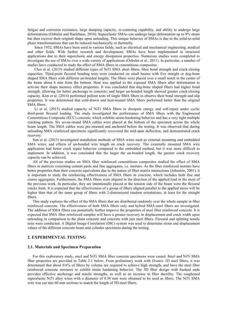
Two main tests were conducted on the prepared concrete specimens: third point loading ASTM C1609 and splitting tensile ASTM C496 testing methods. MTS acquisition system was used to record displacement and force data for each test. The third point bend tests were conducted in displacement control at a rate of 0.889 mm/min. The flexural tests were performed under the cyclic loading. For this test, a concrete specimen with 100% steel fibers was loaded until failure to determine the displacement and force limits for the following cyclic load testing. Subsequent specimens were loaded in increasing displacement increments and unloaded. As a result, it was decided that flexural beams should be loaded at 0.51 mm increasing increments for a total of 8 cycles (about 4 mm of total displacement). Figure 2.1 illustrates the cyclic load history. The splitting tensile tests were also conducted in displacement control at a rate of 0.66 mm/min.
Ingredients Proportions Weight [kg/m3] Water 0.5 158 Cement Type I/II 1.0 332 Boral Fly Ash 0.3 83 FA: Aylett Natural Sand 2.5 828 CA: 0.5" #78 Crushed Stone 2.6 879
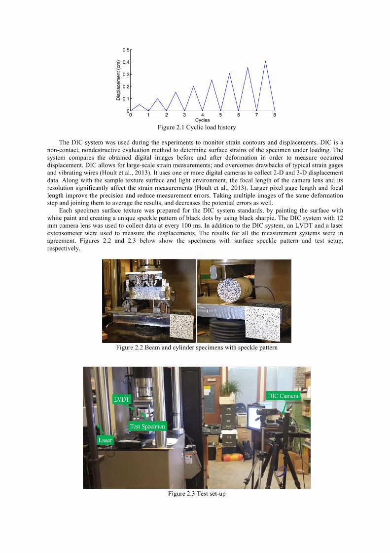
Figure 2.1 Cyclic load history
The DIC system was used during the experiments to monitor strain contours and displacements. DIC is a
non-contact, nondestructive evaluation method to determine surface strains of the specimen under loading. The system compares the obtained digital images before and after deformation in order to measure occurred displacement. DIC allows for large-scale strain measurements; and overcomes drawbacks of typical strain gages and vibrating wires (Hoult et al., 2013). It uses one or more digital cameras to collect 2-D and 3-D displacement data. Along with the sample texture surface and light environment, the focal length of the camera lens and its resolution significantly affect the strain measurements (Hoult et al., 2013). Larger pixel gage length and focal length improve the precision and reduce measurement errors. Taking multiple images of the same deformation step and joining them to average the results, and decreases the potential errors as well.
Each specimen surface texture was prepared for the DIC system standards, by painting the surface with white paint and creating a unique speckle pattern of black dots by using black sharpie. The DIC system with 12 mm camera lens was used to collect data at every 100 ms. In addition to the DIC system, an LVDT and a laser extensometer were used to measure the displacements. The results for all the measurement systems were in agreement. Figures 2.2 and 2.3 below show the specimens with surface speckle pattern and test setup, respectively.
Figure 2.2 Beam and cylinder specimens with speckle pattern
Figure 2.3 Test set-up
0 1 2 3 4 5 6 7 80
0.1
0.2
0.3
0.4
0.5
CyclesD
ispl
acem
ent (
cm)
After flexural testing was completed, the beams were cut into several sections for further testing and analysis. AASHTO T140-1997 or ASTM C116-90 test (Test Method for Compressive Strength of Concrete Using Portions of Beams Broken in Flexure) in combination with British Standard BS EN 123903 (Compressive Strength of Test Specimens) were implemented to determine the compressive strengths of FRC samples. In addition, cross-sections of the beams along the main cracks were analyzed for fiber distribution.
3. EXPERIMENTAL RESULTS 3.1. Tensile Test Results
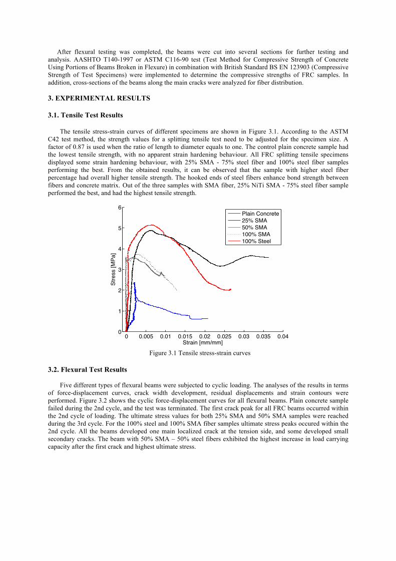
The tensile stress-strain curves of different specimens are shown in Figure 3.1. According to the ASTM C42 test method, the strength values for a splitting tensile test need to be adjusted for the specimen size. A factor of 0.87 is used when the ratio of length to diameter equals to one. The control plain concrete sample had the lowest tensile strength, with no apparent strain hardening behaviour. All FRC splitting tensile specimens displayed some strain hardening behaviour, with 25% SMA - 75% steel fiber and 100% steel fiber samples performing the best. From the obtained results, it can be observed that the sample with higher steel fiber percentage had overall higher tensile strength. The hooked ends of steel fibers enhance bond strength between fibers and concrete matrix. Out of the three samples with SMA fiber, 25% NiTi SMA - 75% steel fiber sample performed the best, and had the highest tensile strength.
Figure 3.1 Tensile stress-strain curves
3.2. Flexural Test Results
Five different types of flexural beams were subjected to cyclic loading. The analyses of the results in terms
of force-displacement curves, crack width development, residual displacements and strain contours were performed. Figure 3.2 shows the cyclic force-displacement curves for all flexural beams. Plain concrete sample failed during the 2nd cycle, and the test was terminated. The first crack peak for all FRC beams occurred within the 2nd cycle of loading. The ultimate stress values for both 25% SMA and 50% SMA samples were reached during the 3rd cycle. For the 100% steel and 100% SMA fiber samples ultimate stress peaks occured within the 2nd cycle. All the beams developed one main localized crack at the tension side, and some developed small secondary cracks. The beam with 50% SMA – 50% steel fibers exhibited the highest increase in load carrying capacity after the first crack and highest ultimate stress.
0 0.005 0.01 0.015 0.02 0.025 0.03 0.035 0.040
1
2
3
4
5
6
Strain [mm/mm]
Stre
ss [M
Pa]
Plain Concrete25% SMA50% SMA100% SMA100% Steel

Figure 3.2 Cyclic force-displacement curves
Figure 3.3 shows the crack width development during loading and unloading cycles of the flexural cyclic
tests. Beams with combined SMA and steel fibers displayed better crack width recovery than the beams with only SMA or only steel fibers. The 50% SMA – 50% steel fiber samples had the smallest crack width at the maximum load and unloading points after 4th cycle. The crack width of that sample was about 0.52 cm by the end of the last cycle. The 100% steel fiber sample displayed largest crack width at the maximum load points; however, its crack width was about 0.61 cm upon last unloading cycle.
Figure 3.3 Crack width development as a function of loading cycle
0 0.1 0.2 0.3 0.4 0.5 0.60
5
10
15
Displacement (cm)
Forc
e (K
N)
Plain concrete
0 0.1 0.2 0.3 0.4 0.5 0.60
5
10
15
Displacement (cm)
Forc
e (K
N)
25% SMA
0 0.1 0.2 0.3 0.4 0.5 0.60
5
10
15
Displacement (cm)
Forc
e (K
N)
50% SMA
0 0.1 0.2 0.3 0.4 0.5 0.60
5
10
15
Displacement (cm)
Forc
e (K
N)
100% SMA
0 0.1 0.2 0.3 0.4 0.5 0.60
5
10
15
Displacement (cm)
Forc
e (K
N)
100% Steel
0 1 2 3 4 5 6 7 80
0.1
0.2
0.3
0.4
0.5
0.6
0.7
0.8
0.9
Cycles
Cra
ck W
idth
(cm
)
25% SMA50% SMA100% SMA100% Steel

Figure 3.4 shows the maximum mid-span deflection at each loading cycle. It can be seen that 25% SMA – 75% steel fiber specimen had the largest deflections, while the deflection for the other specimens were comparable.
Figure 3.4 Mid-span deflection as a function of loading cycle
Figure 3.5 displays the beam strain contours at the first crack during the 2nd loading cycle and upon last
unloading cycle. All beams formed one main crack at the tension zone, and the crack width increased with each loading cycle. It can be seen that 100% steel fiber specimen developed a larger crack at the end of last loading cycle as compared to the samples with SMA fibers.
100% Steel 25% SMA 50% SMA 100% SMA Strain(%)
(a)
(b)
Figure 3.5 Full-field strain measurements with DIC (a) at the first cracking and (b) after unloading of 8th cycle
The flexural beams were cut into several sections. Each beam produced two 76 mm x 76 mm by 76 mm
cubes and two sections from each side of the crack. The cubes were tested to obtain the compressive strength of FRC samples. The addition of fibers usually does not significantly affect the compressive strength of concrete. The average compressive strength of all FRC was about 48 MPa.
Fiber distribution at the beam cross-sections was analysed along the left and right sides of the crack. It was determined that the bottom face of the 50% SMA – 50% steel fiber beam had about 55% of the total amount of fibers at the crack location. However, the 25% SMA – 75% steel fiber sample had only about 30% of the total fibers. Figure 3.6 shows the fiber distribution at a cross-section located at one side of the crack for each type of beam.
(a) (b) (c) (d) Figure 3.6 Fiber distribution at the crack cross-section: a) 100% steel, b) 25% SMA – 75% steel, c) 50% SMA –
50% steel, d) 100% SMA
1 2 3 4 5 6 7 80
0.1
0.2
0.3
0.4
0.5
0.6
0.7
Cycles
Mid
span
Def
lect
ion
(cm
)
25% SMA50% SMA100% SMA100% Steel

4. CONCLUSIONS
This preliminary experimental investigation studied the performance of SMA fibers in fiber reinforced concrete. The specimens with 100% SMA fibers, 100% steel fibers, 50% SMA fibers – 50% steel fibers, 50% SMA fibers – 50% steel fibers were prepared. All the specimens had a fiber volume ratio of 0.6%. Both splitting tensile tests and cyclic flexural tests were conducted. The strains and displacements were measured using a DIC system. The tensile test results shows that increasing the SMA fiber percentage decreases the tensile strength. This can be attributed due to the lower tensile strength of SMA fibers and their straight ends. The tensile behavior of the specimen with 25% SMA and 75% steel fibers was comparable with that of the 100% steel fiber sample. Flexural test results indicate that SMA fibers reduce the crack width and development. However, there was no significant improvement in permanent deformation recovery in the samples with the SMA fibers. The considerable crack recovery reported for the fiber reinforced mortars with aligned SMA fibers in the literature was not observed in the fiber reinforced concrete with randomly distributed SMA fibers. Future studies should consider the use of SMA fibers with improved pullout resistance instead of straight fibers and more efficient mixing procedures for better fiber distribution. AKCNOWLEDGEMENT
The authors would like to acknowledge the support of the Mid-Atlantic Transportation Sustainability University Transportation Center (MATS UTC). Moreover, the authors would like to acknowledge the help and advice of Virginia Center for Transportation Innovation and Research, specifically Michael Burton, Kenneth Herrick, William Ordel, and Jonathon Tanks, M.S. REFERENCES
1. Abrishambaf, A., Cunha, V. M. C. F., and Barros, J. A. O. (2015). The influence of fibre orientation on the post-cracking tensile behaviour of steel fibre reinforced self-compacting concrete. Frattura Ed Integrità Strutturale (Fracture and Structural Integrity), 31, 38–53.
2. ACI 544-1R. (2002). State-of-the-Art Report on Fiber Reinforced Concrete Reported by ACI Committee 544 (Vol. 96).
3. Choi, E., Kim, D. J., Chung, Y., Kim, H. S., and Jung, C. (2015). Crack-closing of cement mortar beams using NiTi cold-drawn SMA short fi bers. Smart Materials and Structures, 24(1), 11.
4. Holschemacher, K., Mueller, T., and Ribakov, Y. (2010). Effect of steel fibres on mechanical properties of high-strength concrete. Materials and Design, 31(5), 2604–2615.
5. Hoult, N. A., Take, W. A., Lee, C., and Dutton, M. (2013). Experimental accuracy of two dimensional strain measurements using Digital Image Correlation. Engineering Structures, 46, 718–726.
6. Johnston, C. D. (2001). Fiber-reinforced cements and concretes. Gordon and Breach Publishers, Amsterdam. 7. Kim, D. J., Kim, H. A., Chung, Y.-S., and Choi, E. (2014). Composites : Part B Pullout resistance of straight
NiTi shape memory alloy fibers in cement mortar after cold drawing and heat treatment. COMPOSITES PART B, 67, 588–594.
8. Kosmatka, S. H., & Wilson, M. L. (2011). Design and Control of Concrete Mixtures (15th ed.). Skokie, Illinois, USA: Portland Cement Association.
9. Li, X., Li, M., and Song, G. (2015). Energy-dissipating and self-repairing SMA-ECC composite material system. Smart Materials and Structures, 24(2), 1–15.
10. Ozbulut, O. E., and Hurlebaus, S. (2010). Neuro-fuzzy modeling of temperature- and strain-rate-dependent behavior of NiTi shape memory alloys for seismic applications. Journal of Intelligent Material Systems and Structures, 21, 837-849.
11. Ozbulut, O. E., Hurlebaus, S., and DesRoches, R. (2011). Seismic response control using shape memory alloys: A Review. Journal of Intelligent Material Systems and Structures, 22, 1531-1549.
12. Shajil, N., Srinivasan, S. M., and Santhanam, M. (2012). Self-centering of shape memory alloy fiber reinforced cement mortar members subjected to strong cyclic loading. Materials and Structures, 651–661.
13. Sun, L., Liang, D., Gao, Q., and Zhou, J. (2013). Analysis on factors affecting the self-repair capability of SMA wire concrete beam. Mathematical Problems in Engineering, 2013, 6.