Experimental Investigation On MIG Welded Mild...
19
International Journal of Machine and Construction Engineering ISSN (Online): 2394 – 3025. Volume 2 Issue 1 Mar 2015 Experimental Investigation On MIG Welded Mild Steel S.Sivakumar 1 , J.R.Vinod Kumar 2 1 PG scholar, Department of Mechanical engineering,Mahendra engineering college, Namakkal. 2 Assistant professor, Department of Mechanical engineering,Mahendra engineering college, Namkkal. Abstract-Gas Metal Arc Welding (GMAW) process is leading in the development in arc welding process which is higher productivity and good in quality. In this study, the effects of different parameters on welding penetration, micro structural and hardness measurement in mild steel that having the 6mm thickness of base metal by using gas metal arc welding will be investigated. The variables that choose in this study are arc voltage, welding current and welding speed. The arc voltage and welding current were chosen as 22, 26 and 30 V and 90, 150 and 210 A respectively. The welding speed was chosen as 20,40 and 60 cm/min. The penetration, microstructure and hardness will be measured for each specimen after the welding process and the effect of it was studied. As a result, it obvious that increasing the parameters value of welding current increased the value of depth of penetration. Other than that, arc voltage and welding speed is another factor that influenced the value of depth of penetration. Keywords: Gas Metal Arc Welding (GMAW), welding penetration, micro structural, hardness measurement I .INTRODUCTION A. Introduction Gas metal arc welding (GMAW), sometimes referred to by its subtypes metal inert gas (MIG) welding or metal active gas (MAG) welding, is a welding process in which an electric arc forms between a consumable wire electrode and the work piece metal(s), which heats the work piece metal(s), causing them to melt, and join. Along with the wire electrode, a shielding gas feeds through the welding gun, which shields the process from contaminants in the air. The process can be semi-automatic or automatic. A constant voltage, direct current power source is most commonly used with GMAW, but constant current systems, as well as alternating current, can be used. GMAW is currently one of the most popular welding methods, especially in industrial environments. It is used extensively by the sheet metal industry and, by extension, the automobile industry. B. History of GMAW (MIG Welding) The principles of gas metal arc welding began to be understood in the early 19th century, after Humphrey Davy discovered the short pulsed electric arcs in 1800. Vasily Petrov independently produced the continuous electric arc in 1802 (soon followed by Davy).It was not until the 1880s that the technology became developed with the aim of industrial usage. At first, carbon electrodes were used in carbon arc welding. By 1890, metal electrodes had been invented by Nikolay Slavyanov and C. L. Coffin. In 1920, an early predecessor of GMAW was invented by P. O. Nobel of General Electric. It used a bare electrode wire and direct current, and used arc voltage to regulate ijmce
Transcript of Experimental Investigation On MIG Welded Mild...

International Journal of Machine and Construction Engineering ISSN (Online): 2394 – 3025. Volume 2 Issue 1 Mar 2015
Experimental Investigation On MIG Welded Mild Steel
S.Sivakumar1, J.R.Vinod Kumar
2
1PG scholar, Department of Mechanical engineering,Mahendra engineering college,
Namakkal. 2Assistant professor, Department of Mechanical engineering,Mahendra engineering
college, Namkkal. Abstract-Gas Metal Arc Welding (GMAW) process is leading in the development in arc welding
process which is higher productivity and good in quality. In this study, the effects of different parameters on welding penetration, micro structural and hardness measurement in mild steel that having the 6mm thickness of base metal by using gas metal arc welding will be investigated. The variables that choose in this study are arc voltage, welding current and welding speed. The arc voltage and welding current were chosen as 22, 26 and 30 V and 90, 150 and 210 A respectively. The welding speed was chosen as 20,40 and 60 cm/min. The penetration, microstructure and hardness will be measured for each specimen after the welding process and the effect of it was studied. As a result, it obvious that increasing the parameters value of welding current increased the value of depth of penetration. Other than that, arc voltage and welding speed is another factor that influenced the value of depth of penetration.
Keywords: Gas Metal Arc Welding (GMAW), welding penetration, micro structural, hardness measurement
I .INTRODUCTION
A. Introduction Gas metal arc welding (GMAW), sometimes referred to by its subtypes metal inert gas (MIG) welding
or metal active gas (MAG) welding, is a welding process in which an electric arc forms between a
consumable wire electrode and the work piece metal(s), which heats the work piece metal(s), causing
them to melt, and join. Along with the wire electrode, a shielding gas feeds through the welding gun,
which shields the process from contaminants in the air. The process can be semi-automatic or
automatic. A constant voltage, direct current power source is most commonly used with GMAW, but
constant current systems, as well as alternating current, can be used. GMAW is currently one of the
most popular welding methods, especially in industrial environments. It is used extensively by the
sheet metal industry and, by extension, the automobile industry.
B. History of GMAW (MIG Welding)
The principles of gas metal arc welding began to be understood in the early 19th century, after
Humphrey Davy discovered the short pulsed electric arcs in 1800.Vasily Petrov independently
produced the continuous electric arc in 1802 (soon followed by Davy).It was not until the 1880s that
the technology became developed with the aim of industrial usage. At first, carbon electrodes were
used in carbon arc welding. By 1890, metal electrodes had been invented by Nikolay Slavyanov and
C. L. Coffin. In 1920, an early predecessor of GMAW was invented by P. O. Nobel of General
Electric. It used a bare electrode wire and direct current, and used arc voltage to regulate ijmce

International Journal of Machine and Construction Engineering ISSN (Online): 2394 – 3025. Volume 2 Issue 1 Mar 2015
the feed rate. It did not use a shielding gas to protect the weld, as developments in welding
atmospheres did not take place until later that decade. In 1948, GMAW was finally developed by the
Battelle Memorial Institute. It used a smaller diameter electrode and a constant voltage power source
developed by H.E. Kennedy. It offered a high deposition rate, but the high cost of inert gases limited
its use to non-ferrous materials and prevented cost savings. In 1953, the use of carbon dioxide as a
welding atmosphere was developed, and it quickly gained popularity in GMAW, since it made
welding steel more economical. In 1958 and 1959, the short-arc variation of GMAW was released,
which increased welding versatility and made the welding of thin materials possible while relying on
smaller electrode wires and more advanced power supplies. It quickly became the most popular
GMAW variation.
B. MIG Welding Overview
Gas Metal Arc Welding (GMAW) is a welding process which joins metals by heating the metals to
their melting point with an electric arc. The arc is between a continuous, consumable electrode wire
and the metal being welded. The arc is shielded from contaminants in the atmosphere by a shielding
gas. GMAW is currently one of the most popular welding methods, especially in industrial
environments. It is used extensively by the sheet metal industry and, by extension, the automobile
industry. There, the method is often used for arc spot welding, thereby replacing riveting or resistance
spot welding. It is also popular for automated welding, in which robots handle the work pieces and the
welding gun to speed up the manufacturing process.Generally, it is unsuitable for welding outdoors,
because the movement of the surrounding air can dissipate the shielding gas and thus make welding
more difficult, while also decreasing the quality of the weld. The problem can be alleviated to some
extent by increasing the shielding gas output, but this can be expensive and may also affect the quality
of the weld. In general, processes such as shielded metal arc welding and flux cored arc welding are
preferred for welding outdoors, making the use of GMAW in the construction industry rather limited. Gas metal arc welding is a gas shielded process that can be effectively used in all positions. The
shielding gas can be both inert gas like argon and active gases like argon-oxygen mixture and argon-
carbon-di-oxide which are chemically reactive.. Gas metal arc welding (GMAW) process is shown in
figure1.1. It can be used on nearly all metals including carbon steel, stainless steel, alloy steel and
aluminium. Arc travel speed is typically 30-38 cm/minute and weld metal deposition rate varies from
1.25 kg/hr when welding out of position to 5.5 kg/hr in flat position. MIG welding is a well
established semi-automatic process. Continuous welding with coiled wire helps high metal
depositions rate and high welding speed
Fig 1 Sketch of the Gas Metal Arc Welding process (GMAW)
ijmce

International Journal of Machine and Construction Engineering ISSN (Online): 2394 – 3025. Volume 2 Issue 1 Mar 2015
The GMAW process has the advantages of
1. No flux required 2. Increased corrosion resistance 3. Easily automated welding 4. Welds all metals including aluminium and stainless steel 5. Low skill factor required to operate MIG 6. Can weld quicker and with more efficiency
The GMAW process has the applications of 1. Automotive sub-assemblies and bodywork, 2. Ship building and ship repair yards. 3. Heavy-duty MIG for lorry chassis and off-highway vehicles 4. Structural steelwork for the construction industry 5. Assembly of white goods and office furniture
Welding Of Mild Steels
Mild steel is the most common form of steel as its price is relatively low while it provides material
properties that are acceptable for many applications. Mild steel has a low carbon content (up to 0.3%)
and is therefore neither extremely brittle nor ductile. It becomes malleable when heated, and so can be
forged. It is also often used where large amounts of steel need to be formed, for example as structural
steel.
Mild steel is usually carbon manganese steel. Traditional mild steel used to contain less than 0.10%
carbon in Iron but it is rare these days. Now carbon manganese steels have taken over and are
commonly called mild steel. They contain more carbon and also Manganese which improves the
strength whilst retaining the ductility / malleability. This mild steel is used in the making of vehicle
frames, panels, boxes, cases and sheet metal for roofs. It is now also used as a replacement for
wrought iron in the making railroad rails.
D. Shielding gases
Shielding gases are necessary for gas metal arc welding to protect the welding area from atmospheric
gases such as nitrogen and oxygen. The choice of a shielding gas depends on several factors, most
importantly the type of material being welded and the process variation being used. Pure inert gases
such as argon and helium are only used for nonferrous welding; with steel they do not provide
adequate weld penetration (argon) or cause an erratic arc and encourage spatter (with helium). Pure
carbon dioxide. On the other hand, allows for deep penetration welds but encourages oxide formation,
which adversely affect the mechanical properties of the weld. lts low cost makes it an attractive
choice, but because of the reactivity of the arc plasma, spatter is unavoidable and welding thin
materials is difficult. As a result, argon and carbon dioxide are frequently mixed in a 75%/25% to
90%/10% mixture. Generally, in short circuit GMAW, higher carbon dioxide content increases the
weld heat and energy when all other weld parameters (volts, current, electrode type and diameter) are
held the same. As the carbon dioxide content increases over 20%, spray transfer GMAW becomes
increasingly problematic, especially with smaller electrode diameters.
ijmce

International Journal of Machine and Construction Engineering ISSN (Online): 2394 – 3025. Volume 2 Issue 1 Mar 2015
Shielding gas mixtures of three or more gases are also available. Mixtures of argon, carbon dioxide
and oxygen are marketed for welding steels. Other mixtures add a small amount of helium to argon-
oxygen combinations, these mixtures are claimed to allow higher arc voltages and welding speed.
Helium also sometimes serves as the base gas, with small amounts of argon and carbon dioxide added.
However, because it is less dense than air, helium is less effective at shielding the weld than argon
which is denser than air. It also can lead to arc stability and penetration issues, and increased spatter,
due to its much more energetic arc plasma. Helium is also substantially more expensive than other
shielding gases. Other specialized and often proprietary gas mixtures claim even greater benefits for
specific applications. The desirable rate of shielding-gas flow depends primarily on weld geometry, speed, current, the type
of gas, and the metal transfer mode. Welding flat surfaces requires higher flow than welding grooved
materials, since gas disperses more quickly. Faster welding speeds, in general, mean that more gas
must be supplied to provide adequate coverage. Additionally, higher current requires greater flow, and
generally, more helium is required to provide adequate coverage than if argon is used. CO2 Gas
CO2 gas is used as the shielding gas in GMA welding of steel plates. The flow characteristics of CO2
are such that the gas issues in a non-turbulent manner from the MIG gun. With CO2 shielding the
metal transfer will be globular and non-axial at low current densities. MIG/CO2 welding with spray
type arc (current density 350 amps) is best suited for welding relatively thick parts. For thin sheets dip
transfer technique is used with low arc voltage (16 - 22 V) and low current (60 - 180 amps). The low
arc voltage results in a reduced arc length and the molten droplet gets transferred into the weld pool
by direct contact. With pure argon or a mixture of argon + 20% CO2, the metal transfer is globular at
low current density, but changes to spray type when the current density increases. In the spray type
transfer the metal travels across the arc in the form of fine droplets which is induced by the magnetic
force acting on the molten electrode tip. CO2 is widely used for welding of mild steel and it gives
sound weld deposits.
E. Electrode
When choosing an electrode, one must consider arc stability, solidification rate, mechanical
properties, deposition rate, base metal compatibility, and parameter settings. Parameter settings for
GMAW electrodes depend on: 1. Diameter of the Electrode 2. Mode of Transfer 3. Shielding Gas Composition 4. Welding Position
The GMAW process uses a consumable, automatically fed wire electrode and is considered a
semiautomatic welding process when welded by hand. Electrode diameters used in GMAW typically
range from 0.024 inches (0.6 mm) to 0.062 inches (1.6 mm). However, electrode diameters are
manufactured from as small as 0.020 inches (0.5 mm) to as large as 1/8 inch (3 mm). As a rule,
electrode size selection is based on base metal thickness, welding position, and mode of metal
transfer. Larger electrodes can obviously provide higher welding speeds and the higher amperages
desired for spray transfer welding on heavier base metals. The most common types of MIG wire for
welding mild steel are ER70S-3 and ER70S-6. ijmce

International Journal of Machine and Construction Engineering ISSN (Online): 2394 – 3025. Volume 2 Issue 1 Mar 2015
ER70S-3 Electrodes of this classification contain a relatively low percentage of deoxidizing elements
(silicon and manganese); however, they are one of the most widely used GMAW wires. They produce
welds of fair quality when used on all types of steels, especially if using Argon-O2 or Argon-CO2 as
a shielding gas. Straight CO2 can be used, but parameters should remain in short-circuit mode. The
use of straight CO2 is not recommended when welding with high voltage and high amperage. When
CO2 shielding gas is used, in the high welding currents (high heat input), welds produced may not
meet the minimum tensile and yield strengths of this specification. High heat input using straight CO2
will burn out the relatively low percentage of deoxidizing elements in this electrode wire. Choose an ER70S-6 wire for welding on plate that has mill scale or surface contaminants, since this
wire incorporates the proper deoxidizer to combat these issues. A deoxidizer absorbs oxygen so that it
vaporizes into the arc or forms as scale oxides. ER70S-6 is also better for creating a smooth transition
from the weld to the base metal, also known as wash-in or tie-in. Better wash-in may be a requirement
in applications subject to fatigue. ER70S-6 wire can provide better wetting at the weld toe when
compared to an ER70S-3 wire. ER70S-6 Electrodes in this classification contain the highest
combination deoxidizers in the form of silicon and manganese. This allows them to be used for
welding all types of carbon steel, even rimmed steels, by using CO2 shielding gas.
II . LITERATURE REVIEW
IzzatulAini Ibrahim et al (2012) studied the effects of different parameters on welding penetration,
micro structural and hardness measurement in mild steel that having the 6mm thickness of base metal
by using the robotic gas metal arc welding are investigated. The variables that choose in this study are
arc voltage, welding current and welding speed. The arc voltage and welding current were chosen as
22, 26 and 30 V and 90, 150 and 210 A respectively. The welding speed was chosen as 20, 40 and 60
cm/min. The penetration, microstructure and hardness were measured for each specimen after the
welding process and the effect of it was studied. As a result, it obvious that increasing the parameters
value of welding current increased the value of depth of penetration. Other than that, arc voltage and
welding speed is another factor that influenced the value of depth of penetration. The micro structure
shown the different grain boundaries of each parameters that affected of the welding parameters.
Kamal pal et al (2010) studied the influence of pulse parameters at various torch angles on the tensile
properties of low carbon steel butt weld in pulsed metal inert gas welding. The interface of weld zone
and heat affected zone was found to be the weakest area due to significant variation of weld
microstructure. The weld bead characteristics strongly influenced the joint strength. An infrared
pyrometer and sound sensor have also been used along with arc sensors to monitor the weld quality.
The arc power and arc sound kurtosis were found to be strongly correlated with weld quality.
Ming Gao et al (2008) studied the laser arc hybrid welding, the weld shape and microstructure
characteristics of laser metal inert gas hybrid welded mild steel were analyzed. The results showed
typical hybrid weld could be classified as two parts: the wide upper zone and the narrow zone, which
were defined as arc zone and laser zone, respectively. In the hybrid weld, the microstructure, alloy
element distribution and micro hardness all have evident difference between laser zone and arc zone.
The microstructure of arc zone consists of coarse columnar dendrite and fine acicular dendrite
between the columnar dendrites, but that of laser zone is composed of fine equiaxed dendrite in weld
center and columnar dendrite around the equiaxed dendrite. Compared to arc zone, laser zone has
finer grain size, higher micro hardness, smaller alloy element content in the fusion zone and narrower
ijmce

International Journal of Machine and Construction Engineering ISSN (Online): 2394 – 3025. Volume 2 Issue 1 Mar 2015
heat affected zone. The discussions demonstrated that the observed difference was caused by the
difference of temperature gradient, crystallizing and the effects of arc pressure on the molten pool
between laser zone and arc zone.
Giovanni Tani et al (2007) studied the Hybrid LASER GMAW welding technique has been recently
studied and developed in order to meet the needs of modern welding industries. The two sources
involved in this process play, in fact, a complementary role: fast welding speed, deep bead penetration
and high energy concentration can be achieved through the LASER beam, while gap bridge ability
and cost-effectiveness are typical of the GMAW process. Particularly interesting, in this context, is
the CO2 LASER MIG welding which differs from the Nd’YAG LASER–MIG technique for the high
powers that can be exploited and for the good power/cost ratio of the process. This paper is a part of a
wide study on the hybrid CO2 LASER MIG welding and investigates the influence of the shielding
gas both on the stability of the process and on the dimensional characteristics of the weld bead. Two
different parameters have been taken into consideration in order to develop this analysis: the shielding
gas composition and the shielding gas flow. The results have been analyzed through a statistical
approach in order to determine the real influence of each parameter on the overall process.
Zielinskaet al (2009) studied the percentage of carbon dioxide in argon induces the increase of the
transition current value from the globular to spray metal transfer mode. This work shows that these
effects are linked to the chemical and micro structural modifications of the anode tip during the gas
metal arc welding process. The microstructure of the anode is investigated for various experimental
conditions. Transition between the two transfer modes is linked to the existence and disappearance of
a rather insulating oxide “gangue” at the wire extremity whose nature depends of the shielding gas. Chemical reactions at high temperature such as oxidation reduction reactions between shielding gas and melted metal govern the transition of the spray-arc to globular transfer mode.
Kimet al (2003) studied the robotic arc welding process involves sophisticated sensing and control
techniques applied to various process variables. One of the major important tasks in the robotic CO2
arc welding process is to understand inter relationship between process variables and bead penetration
and subsequently develop the mathematical models to predict the desired bead penetration. To
achieve the objectives, partial-penetration and single-pass welds were fabricated in 12 mm SS400
plate by using four different process variables. The experimental results were employed to develop
the curvilinear and linear equations, and find the process control algorithms for the CO2 arc welding
process. Mathematical models developed can predict the bead penetration with reasonable accuracy.
The process control algorithms developed will be useful for identifying the various problems that
result from the CO2 arc welding process, and establishing criteria for effective joint design.
Tuseket al (2004) studied the mathematical models for calculation and prediction of melting rate in arc welding with a triple-wire electrode are described. The quantities affecting the melting rate of the filler material were determined by experimental work. Mathematical models with which it is possible
to calculate and predict, with a strong probability, the melting rate in triple-wire arc welding in
different shielding media were elaborated by statistical methods.
UweReisgen et al (2010) studied the effects of shielding gas types and flow rates on CO2 laser
weldability of DP600/TRIP700 steel sheets were studied in this work. The evaluated shielding gases
were helium (He), argon (Ar) and different mixtures of He and Ar. Weld penetration, tensile strength
and formability (Erichsen test) of laser welds were found to be strongly dependent upon the shielding
ijmce

International Journal of Machine and Construction Engineering ISSN (Online): 2394 – 3025. Volume 2 Issue 1 Mar 2015
gas types. The ability of shielding gas in removing plasma plume and thus increasing weld penetration
is believed to be closely related to ionization potential and atomic weight which determine the period
of plasma formation and disappearance. It was found that the higher helium shielding gas flow rate,
the deeper weld penetration and the lower weld width.
Couleset al (2012) studied the strain field within thin steel plates during gas metal arc welding has
been studied using resistance strain gauges and digital image correlation, allowing the initial
formation of stresses around the weld seam to be observed. Major features of the transient stress field
have been identified, and are explained with reference to the underlying thermal and mechanical
processes. A comparison of stresses occurring during bead-on-plate and butt welding shows they are
very similar. The assumptions and limitations associated with determination of the stress state are
addressed, and the application of such methods to the problem of reducing welding residual stresses is
discussed.
Ganjigatti et al (2007) studied the MIG welding process through regression analyses carried out both
globally as well as cluster-wise. It is important to mention that the second approach makes use of the
entropy based fuzzy clusters. The investigation is based on the data collected through full factorial
design of experiments. Results of the above two approaches are compared and some concluding
remarks are made. The cluster-wise regression analysis is found to perform a slightly better than the
global approach in predicting weld bead-geometric parameters.
Ming Gao et al (2012) studied the mechanical properties of welded joints were evaluated by tensile
test. Under the optimal welding parameters, the stable process and sound joints were obtained. The
tensile strength efficiency of welded joints recovered 84–98% of the substrate. It was found that the
arc was compressed and stabilized by the laser beam during the hybrid welding. The compressed
extent of arc column increased with laser power, and the process stability could be improved by
increasing laser power and arc current or slowing welding speed. The arc stabilized mechanism in
laser–MIG hybrid welding of Mg alloys was summarized in two factors. First, the laser keyhole fixes
the arc root and improves the igniting ability of the arc. Second, the electromagnetic force is
downward and increased by the laser–arc interaction, which prevents the overheating of the droplet
and smoothes droplet transfer from the wire to the weld pool.
RakeshMalviya et al (2011) studied the optimization technique has been used for tuning of neural
networks utilized for carrying out both forward and reverse mappings of metal inert gas (MIG)
welding process. Four approaches have been developed and their performances are compared to solve
the said problems. The first and second approaches deal with tuning of multi-layer feed-forward
neural network and radial basis function neural network, respectively. In the third and fourth
approaches, a back-propagation algorithm has been used along with particle swarm optimization to
tune radial basis function neural network. Moreover, in these two approaches, two different clustering
algorithms have been utilized to decide the structure of the network. The performances of hybrid
approaches (that is, the third and fourth approaches) are found to be better than that of the other two. ijmce

International Journal of Machine and Construction Engineering ISSN (Online): 2394 – 3025. Volume 2 Issue 1 Mar 2015
III. METHODOLOGY
A. Selection of material Mild steel
Mild steel is steel in which the main interstitial alloying constituent is carbon in the range of 0.12–
2.0%. The American Iron and Steel Institute (AISI) defines carbon steel as the following: "Steel is
considered to be carbon steel when no minimum content is specified or required for chromium,
cobalt,molybdenum, nickel, niobium, titanium, tungsten, vanadium or zirconium, or any other element
to be added to obtain a desired alloying effect; when the specified minimum for copper does not
exceed 0.40 percent; or when the maximum content specified for any of the following elements does
not exceed the percentages noted: manganese 1.65, silicon 0.60, copper 0.6. Mild steel – A36 material
A36 is the most commonly used mild and hot-rolled steel. It has excellent welding properties and is
suitable for grinding, punching, tapping, drilling and machining processes. Yield strength of ASTM
A36 is less than that of cold roll C1018, thus enabling ASTM A36 to bend more readily than C1018.
The view of Mild steel A36 plate is shown in Figure 1.A36 is produced in a wide variety of forms,
including rectangle bar, square bar, circular rod, steel shapes such as channels, angles, H-beams and I-
beams. ASTM A36 steel is easy to weld using any type of welding methods and the welds and joints
so formed are of excellent quality.
Fig 1 Mild steel A36 plate
The A36 standard was established by the standards organization ASTM International. A36 is readily
welded by nearly all welding processes and the specification of the mild steel A36 plate shown in the
following Table 1.
ijmce

International Journal of Machine and Construction Engineering
ISSN (Online): 2394 – 3025. Volume 2 Issue 1 Mar 2015
Table 1 Specification of the Mild steel A36 plate
Length Height Thickness Material No of
specimens
100 50 mm 6 mm Mild steel 12
mm
Therefore the most commonly used for A36 are those which are cheapest and easiest. A36 steel and
their chemical composition shown in following Table 2. It is also commonly used in bolted and
riveted in structural applications and their mechanical properties shown in the following Table 3.
Table 2 Chemical composition of Mild steel A36 plate
Element (%) present
Fe 98.70
C 0.0652
Si 0.158
Mn 0.919
P 0.035
S 0.011
Cr 0.0861
Mo 0.015
Ti 0.0071
V 0.0021
Pb 0.0013
Table 3 Mechanical properties of Mild steel A36
Property Value
Yield Strength 289 Typical Mpa
Tensile Strength 397 Typical Mpa
Brinell Hardness 229 Typical HV
Elongation 33.2 %
Charpy Impact 5.4 joule
ijmce
International Journal of Machine and Construction Engineering ISSN (Online): 2394 – 3025. Volume 2 Issue 1 Mar 2015
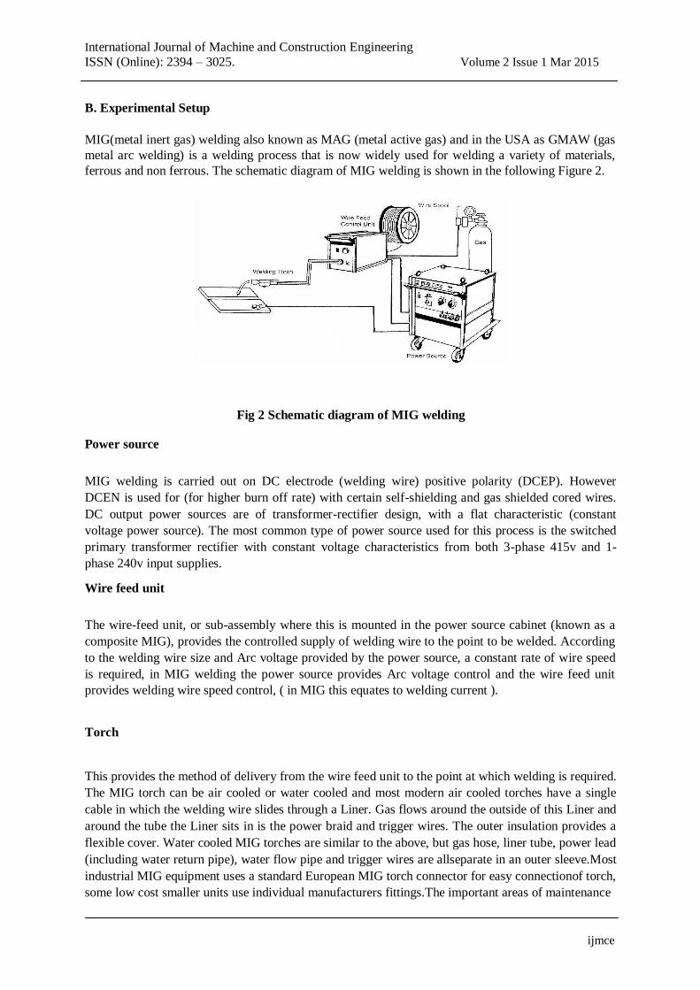
B. Experimental Setup
MIG(metal inert gas) welding also known as MAG (metal active gas) and in the USA as GMAW (gas
metal arc welding) is a welding process that is now widely used for welding a variety of materials,
ferrous and non ferrous. The schematic diagram of MIG welding is shown in the following Figure 2.
Fig 2 Schematic diagram of MIG welding Power source
MIG welding is carried out on DC electrode (welding wire) positive polarity (DCEP). However
DCEN is used for (for higher burn off rate) with certain self-shielding and gas shielded cored wires.
DC output power sources are of transformer-rectifier design, with a flat characteristic (constant
voltage power source). The most common type of power source used for this process is the switched
primary transformer rectifier with constant voltage characteristics from both 3-phase 415v and 1-
phase 240v input supplies. Wire feed unit
The wire-feed unit, or sub-assembly where this is mounted in the power source cabinet (known as a
composite MIG), provides the controlled supply of welding wire to the point to be welded. According
to the welding wire size and Arc voltage provided by the power source, a constant rate of wire speed
is required, in MIG welding the power source provides Arc voltage control and the wire feed unit
provides welding wire speed control, ( in MIG this equates to welding current ). Torch
This provides the method of delivery from the wire feed unit to the point at which welding is required.
The MIG torch can be air cooled or water cooled and most modern air cooled torches have a single
cable in which the welding wire slides through a Liner. Gas flows around the outside of this Liner and
around the tube the Liner sits in is the power braid and trigger wires. The outer insulation provides a
flexible cover. Water cooled MIG torches are similar to the above, but gas hose, liner tube, power lead
(including water return pipe), water flow pipe and trigger wires are allseparate in an outer sleeve.Most
industrial MIG equipment uses a standard European MIG torch connector for easy connectionof torch,
some low cost smaller units use individual manufacturers fittings.The important areas of maintenance
ijmce

International Journal of Machine and Construction Engineering ISSN (Online): 2394 – 3025. Volume 2 Issue 1 Mar 2015
are: Liners are in good condition and correct type and size; Contact tips are lightly fitted, of correct size and good condition.
Shielding Gas
This is a complicated area with many various mixtures available, but the primary purpose of
the shielding gas in the MIG process is to protect the molten weld metal and heat affected zone from
oxidation and other contamination by the atmosphere.The shielding gas should also have a
pronounced effect on the following aspects of the welding operation and the resultant weld.
C. Tests Conducted
By varying the process parameters the metal inert gas weldedA36 material to the following test under mechanical properties.
1. Mechanical properties 1. Tensile test 2. Brinell hardness test 3. Impact test
Mechanical properties
Mechanical testing plays an important role in evaluating fundamental properties of engineering
materials as well as in developing new materials and in controlling the quality of materials for use in
design and construction. If a material is to be used as part of an engineering structure that will be
subjected to a load, it is important to know that the material is strong enough and rigid enough to
withstand the loads that it will experience in service. As a result engineers have developed a number
of experimental techniques for mechanical testing of engineering materials subjected to tension,
compression, bending or torsion loading. a.Tensile test
The most common type of test used to measure the mechanical properties of a material is the tensile
test and the machine is shown in Figure 3. Tensile test is widely used to provide a basic design
information on the strength of materials and is an acceptance test for the specification of materials.
The major parameters that describe the stress-strain curve obtained during the tension test are the
tensile strength (UTS), yield strength or yield point (σy), elastic modulus (E), percent elongation
(ΔL%) and the reduction in area (RA%). Toughness, Resilience, Poisson’s ratio (ν) can also be found
by the use of this testing technique.
ijmce

International Journal of Machine and Construction Engineering ISSN (Online): 2394 – 3025. Volume 2 Issue 1 Mar 2015
a) Screw driven machine b) a hydraulic testing machine Fig 3 Tensile testing machines
Testing system
The testing system consists of a tensile testing machine, a load cell, a power supply and an x-y recorder. 1. Testing Machine is a load-controlled machine. 2. Load Cell provides an electrical circuit for measuring the instantaneous load along the loading axis. 3. Power Supply is connected to load cell. It feeds the load cell, amplifies the output signal and displays the load. 4. Recorder plots the variation of load against time. 5. Specimen tensile specimens are machined in the desired orientation and according to the standards.
The central portion (gage portion) of the length is usually of smaller cross section than the end
portions. This ensures the failure to occur at a section where the stresses are not affected by the
gripping device. The gage length is marked and elongation is measured between these markings
during the test.
Procedure
1. Before the test 1. Put gage marks on the specimen 2. Measure the initial gage length and diameter 3. Select a load scale to deform and fracture the specimen. Note that that tensile strength of the material type used has to be known approximately.
During the test 1. Record the maximum load 2. Conduct the test until fracture.
After the test 1. Measure the final gage length and diameter. The diameter should be measured from the neck.
ijmce

International Journal of Machine and Construction Engineering ISSN (Online): 2394 – 3025. Volume 2 Issue 1 Mar 2015
b..Brinell hardness test
Hardness is the property of a material that enables it to resist plastic deformation, usually by
penetration. However, the term hardness may also refer to resistance to bending, scratching, abrasion
or cutting.
The Brinell hardness test method consists of indenting the test material with a 10 mm diameter
hardened steel or carbide ball subjected to a load of 3000 kg and the schematic view of the brinell
hardness test is shown in Figure 4. For softer materials the load can be reduced to 1500 kg or 500 kg
to avoid excessive indentation. The full load is normally applied for 10 to 15 seconds in the case of
iron and steel and for at least 30 seconds in the case of other metals. The diameter of the indentation
left in the test material is measured with a low powered microscope. The Brinell harness number is
calculated by dividing the load applied by the surface area of the indentation.
Fig 4 schematic diagram of the brinell hardness test
The diameter of the impression is the average of two readings at right angles and the use of a Brinell
hardness number table can simplify the determination of the Brinell hardness. A well
structuredBrinell hardness number reveals the test conditions, and looks like this, "75 HB 10/500/30"
which means that a Brinell Hardness of 75 was obtained using a 10mm diameter hardened steel with a
500 kilogram load applied for a period of 30 seconds. On tests of extremely hard metals a tungsten
carbide ball is substituted for the steel ball. Compared to the other hardness test methods, the Brinell
ball makes the deepest and widest indentation, so the test averages the hardness over a wider amount
of material, which will more accurately account for multiple grain structures and any irregularities in
the uniformity of the material. This method is the best for achieving the bulk or macro-hardness of a
material, particularly those materials with heterogeneous structures. c. Charpy impact test
The Charpy impact test, also known as the Charpy V-notch test, is a standardized high strain-rate test
which determines the amount of energy absorbed by a material during fracture and the schematic
diagram of the charpy impact test is shown in Figure 5. This absorbed energy is a measure of a given
material's notch toughness and acts as a tool to study temperature-dependent ductile-brittle transition.
ijmce

International Journal of Machine and Construction Engineering ISSN (Online): 2394 – 3025. Volume 2 Issue 1 Mar 2015
Fig 5 Schematic diagram of the charpy impact test
The test consists of breaking by one blow from a swinging pendulum, under conditions defined by
standards, a test piece notched in the middle and supported at each end. The energy absorbed is
determined in joules. This absorbed energy is a measure of the impact strength of a material.
The test bar, notched in the centre, is located on two supports. The hammer will fracture the test bar and the absorbed energy (in Joule) is an indication for the resistance of the material to shock loads.
IV .RESULTS AND DISCUSSION
A. Mechanical Properties
By varying the process parameters the metal inert gas welded mild steel A36 material which exhibited
good mechanical properties. The following tests are conducted under mechanical properties which
indicate the success of the process. 1. Tensile test. 2. Brinell hardness test. 3. Charpy impact test. Tensile test
By following the ASTM E8 standard shown in Figure 6 the tensile specimens are prepared from the
welded specimens.The tensile tests are conducted for all the tensile specimen and their results are
indicated in the following Table 4 and values of tensile strength are also shown in Graph no 1.
ijmce

International Journal of Machine and Construction Engineering ISSN (Online): 2394 – 3025. Volume 2 Issue 1 Mar 2015
Fig 6 ASTM E8 standard
The tensile strength is calculated by the following formula
Tensile strength = Load at break in (N/mm2)
Thickness × Width
Table 4 Tensile test results
Specimen
Current Voltage Area
Load at Tensile
break strength
No
(Amps) (Volts) (thicknes×width)
(Newton) (N/mm2)
1. 110 22 36 14400 400
2. 120 23 36 15555 432
3. 130 24 36 16160 456
4. 140 25 36 17280 488
Base metal 36 14400 397
Graph no 1 Tensile strength graph for all specimens
ijmce

International Journal of Machine and Construction Engineering ISSN (Online): 2394 – 3025. Volume 2 Issue 1 Mar 2015
Brinell hardness test
The brinell hardness test are conducted for the metal inert gas welded specimens and the hardness are
taken in the welding zone as well as in the base metal of the advancing side and retreating side and
their results are shown in the following Table 5.The brinell hardness test graph for the individual
specimen is shown in the following Graph no 2, 3, 4, 5, 6. The hardness is calculated by the following
formula BHN = F
π D – (D - √D2 - Di)
F = Applied force = 250 kgf D = Indenter Diameter = 5 mm Ball
Di = Indentation Diameter
Table 5 Hardness test result
Adva Retre
ncin
ating
g
side
side
Spe Cur Volt Base Wel
ding Base
cim rent age meta
zone metal
en (Am (Vol l
(WZ (BM)
no ps) ts) (BM)
)
1. 110 22 229 285 229
2. 120 23 229 285 229
3. 130 24 187 229 187
4. 140 25 229 285 229
1. Specimen no 1
Graph no 2 Brinell hardness graph for specimen no 1
ijmce

International Journal of Machine and Construction Engineering ISSN (Online): 2394 – 3025. Volume 2 Issue 1 Mar 2015
2. Specimen no 2
Graph no 3 Brinell hardness graph for specimen no 2
3. Specimen no 3
Graph no 4 Brinell hardness for graph specimen no 3 4. Specimen no 4
Graph no 5 Brinell hardness graph for specimen no 4 Charpy impact test.
The charpy impact specimens are prepared from the metal inert gas welded specimens. Then the
charpy impact test are conducted for all the specimens and their result are shown in the following
Table 6.
ijmce

International Journal of Machine and Construction Engineering
ISSN (Online): 2394 – 3025. Volume 2 Issue 1 Mar 2015
Table 6 Charpy impact test results
Specimen no
Current (Amps) Voltage (Volts)
Energy absorbed
(joules)
1. 110 22 7
2. 120 23 7.8
3. 130 24 9
4. 140 25 12
Base metal 5.4
Graph no 6 Charpy impact graph for all specimens
V .CONCLUSION
1. The tensile strength for all the metal inert gas welded specimens are ranged from 400 to 488
N/mm2. When compared to base metal the welded specimens exhibit high tensile strength. Therefore
all the metal inert gas welded specimen exhibit good tensile strength. 2. The brinell hardness number are increased for all the metal inert gas welded specimen when compared to the base metal. 3. The charpy impact where all the metal inert gas welded specimen which absorbed more energy when compared to the base metal.
ijmce

International Journal of Machine and Construction Engineering ISSN (Online): 2394 – 3025. Volume 2 Issue 1 Mar 2015
VI REFERENCES
1. IzzatulAini Ibrahim., SyarulAsrafMohamat.,AmalinaAmir.andAbdulGhalib. (2012) “The Effect
of Gas Metal Arc Welding (GMAW) processes on different welding parameters”,Procedia
Engineering, Vol.41, pp.1502 – 1506. 2. Kamal Pal. andSurjya K. Pal. (2010) “Study of weld joint strength using sensor signals for
various torch angles in pulsed MIG welding”, Journal of Manufacturing Science and
Technology, Vol.3, pp. 55–65. 3. Ming Gao., Xiaoyan Zeng., Jun Yan. andQianwu Hu. (2008) “Microstructure characteristics of
laser–MIG hybrid welded mild steel”,Applied Surface Science, Vol.254, pp. 5715–5721. 4. Giovanni Tani., GiampaoloCampana., Alessandro Fortunato. andAlessandroAscari. (2007) “The
influence of shielding gas in hybrid LASER–MIG welding”,Applied Surface Science, Vol.253,
pp. 8050-8053. 5. Zielinska S., Valensi F., Pellerin N., Pellerin S.,Musioł K. andBriand F. (2009) “Microstructural
analysis of the anode in gas metal arc welding (GMAW)”,journal of materials processing
technology, Vol.209, pp. 3581-3591. 6. Kim I.S., Son J.S., Kim I.G., Kim J.Y. andKim Yang O.S. (2003) “A study on relationship
between process variables and bead penetration for robotic CO2 arc welding”,Journal of
Materials Processing Technology, Vol.136, pp. 139-145. 7. Tusek J. (2004) “Mathematical modelling of melting rate in arc welding with a triple-wire
electrode”,Journal of Materials Processing Technology, Vol.146, pp. 415-423. 8. UweReisgen., Markus Schleser., Oleg Mokrov. andEssam Ahmed. (2010) “Shielding gas
influences on laser weldability of tailored blanks of advanced automotive steels”,Applied Surface Science, Vol.257, pp. 1401-1406.
9. Coules H.E., Colegrove P., Cozzolino L.D. andWen S.W. (2012) “Experimental measurement of
biaxial thermal stress fields caused by arc welding”,Journal of Materials Processing Technology,
Vol.212, pp. 962-968. 10. Ganjigatti J.P., Dilip Kumar Pratihar. andRoy ChoudhuryA.(2007) “Global versus cluster-wise
regression analyses for prediction of bead geometry in MIG welding process”,Journal of
Materials Processing Technology, Vol.189, pp. 352-366. 11. Ming Gao., Shuwen Mei., Zemin Wang., Xiangyou Li. and Xiaoyan Zeng.(2012) “Process and
joint characterizations of laser–MIG hybrid welding of AZ31magnesium alloy”, Journal of Materials Processing Technology, Vol.212, pp. 1338-1346.
12. RakeshMalviya. andDilip Kumar Pratihar.(2011) “Tuning of neural networks using particle
swarm optimization to model MIG welding process”, Swarm and Evolutionary Computation,
Vol.1, pp. 223-235.
ijmce