Experimental Investigation of the Performances of a … — This paper describes an experimental...
6
Abstract — This paper describes an experimental investigation conducted on WRS-BTU seismic isolators that are constituted by a wire rope spring coupled with a ball transfer unit. The device can be considered rigid along the vertical direction while the horizontal stiffness can be independently chosen to shift the natural period away from the period range having the most of earthquake energy. Two kinds of tests were carried out: the first ones regard the isolator characterization; then, to evaluate the isolation efficiency, a small laboratory structure was equipped with four isolators and several tests on a shake-table were performed. Index Terms— Seismic isolators, shake-table tests, nonlinear dynamics, wire rope, hysteresis. I. INTRODUCTION new type of seismic isolator was developed and realized at the Department of Industrial Engineering (DII) of the University of Naples Federico II; it is constituted (Fig.1) by the coupling of a ball transfer unit (BTU) with a wire rope spring (WRS). Fig. 1. WRS-BTU isolator. BTU is an omni-directional load-bearing spherical balls mounted inside a restraining fixture, having the task to bear the structure weight with a neglecting vertical deformation (Fig.2); it allows the structure to translate along any R. Brancati is with the Dipartimento di Ingegneria Industriale, Università degli Studi di Napoli Federico II, 80125 ITALY, (e-mail: [email protected]). G. Di Massa is with the Dipartimento di Ingegneria Industriale, Università degli Studi di Napoli Federico II, 80125 ITALY, (e-mail: [email protected]). S. Pagano is with the Dipartimento di Ingegneria Industriale, Università degli Studi di Napoli Federico II, 80125 ITALY, (e-mail: [email protected]). E. Rocca is with the Dipartimento di Ingegneria Industriale, Università degli Studi di Napoli Federico II, 80125 ITALY, (e-mail: [email protected]). S. Strano is with the Dipartimento di Ingegneria Industriale, Università degli Studi di Napoli Federico II, 80125 ITALY, (corresponding author, phone:+390817683277; e-mail:[email protected]). horizontal direction with low friction. Fig. 2. Ball Transfer Unit (BTU) scheme. The isolator restoring force is provided by a wire rope spring (WRS) constituted by several ropes connecting the two plates of the device. WRSs are widely adopted in industrial field as they are particularly effective in vibration isolation and energy absorption. In fact they dissipate energy through friction forces acting among the wires of each rope due to their relative movement; the produced thermal energy is easily exchanged with the environment thanks to favourable heat exchange surface of the ropes. Compared with the elastomeric seismic isolators, WRSs have a longer service life since they are not very sensitive to temperature changes and resists aggressive environments caused by the presence of ozone, oil, grease and salt spray. The most common WRS are helical type (Fig. 3a) or circular type (Fig. 3b). These springs are sometimes called “cable isolators” even if the term cable generally refers to a flexible tension member (rope) which, in addition to a strength member, includes power and/or signal conductors within its structure. Fig. 3. Commercial wire rope spring. The WRS-BTU isolator can be obtained by coupling the two main component, not necessarily integrated into a unique support; the two main component can be chosen in function of the vertical load acting on the BTU and of the WRS horizontal stiffness required to shift the natural period away from the period range having the most of earthquake energy; the choices are facilitated by the numerous technical Experimental Investigation of the Performances of a WRS-BTU Seismic Isolator R. Brancati, G. Di Massa, S. Pagano, E. Rocca and S. Strano A Proceedings of the World Congress on Engineering 2013 Vol III, WCE 2013, July 3 - 5, 2013, London, U.K. ISBN: 978-988-19252-9-9 ISSN: 2078-0958 (Print); ISSN: 2078-0966 (Online) WCE 2013
Transcript of Experimental Investigation of the Performances of a … — This paper describes an experimental...

Abstract — This paper describes an experimental
investigation conducted on WRS-BTU seismic isolators that are constituted by a wire rope spring coupled with a ball transfer unit. The device can be considered rigid along the vertical direction while the horizontal stiffness can be independently chosen to shift the natural period away from the period range having the most of earthquake energy. Two kinds of tests were carried out: the first ones regard the isolator characterization; then, to evaluate the isolation efficiency, a small laboratory structure was equipped with four isolators and several tests on a shake-table were performed.
Index Terms— Seismic isolators, shake-table tests, nonlinear dynamics, wire rope, hysteresis.
I. INTRODUCTION
new type of seismic isolator was developed and realized at the Department of Industrial Engineering
(DII) of the University of Naples Federico II; it is constituted (Fig.1) by the coupling of a ball transfer unit (BTU) with a wire rope spring (WRS).
Fig. 1. WRS-BTU isolator.
BTU is an omni-directional load-bearing spherical balls
mounted inside a restraining fixture, having the task to bear the structure weight with a neglecting vertical deformation (Fig.2); it allows the structure to translate along any
R. Brancati is with the Dipartimento di Ingegneria Industriale,
Università degli Studi di Napoli Federico II, 80125 ITALY, (e-mail: [email protected]).
G. Di Massa is with the Dipartimento di Ingegneria Industriale, Università degli Studi di Napoli Federico II, 80125 ITALY, (e-mail: [email protected]).
S. Pagano is with the Dipartimento di Ingegneria Industriale, Università degli Studi di Napoli Federico II, 80125 ITALY, (e-mail: [email protected]).
E. Rocca is with the Dipartimento di Ingegneria Industriale, Università degli Studi di Napoli Federico II, 80125 ITALY, (e-mail: [email protected]).
S. Strano is with the Dipartimento di Ingegneria Industriale, Università degli Studi di Napoli Federico II, 80125 ITALY, (corresponding author, phone:+390817683277; e-mail:[email protected]).
horizontal direction with low friction.
Fig. 2. Ball Transfer Unit (BTU) scheme. The isolator restoring force is provided by a wire rope
spring (WRS) constituted by several ropes connecting the two plates of the device.
WRSs are widely adopted in industrial field as they are particularly effective in vibration isolation and energy absorption. In fact they dissipate energy through friction forces acting among the wires of each rope due to their relative movement; the produced thermal energy is easily exchanged with the environment thanks to favourable heat exchange surface of the ropes.
Compared with the elastomeric seismic isolators, WRSs have a longer service life since they are not very sensitive to temperature changes and resists aggressive environments caused by the presence of ozone, oil, grease and salt spray.
The most common WRS are helical type (Fig. 3a) or circular type (Fig. 3b). These springs are sometimes called “cable isolators” even if the term cable generally refers to a flexible tension member (rope) which, in addition to a strength member, includes power and/or signal conductors within its structure.
Fig. 3. Commercial wire rope spring. The WRS-BTU isolator can be obtained by coupling the
two main component, not necessarily integrated into a unique support; the two main component can be chosen in function of the vertical load acting on the BTU and of the WRS horizontal stiffness required to shift the natural period away from the period range having the most of earthquake energy; the choices are facilitated by the numerous technical
Experimental Investigation of the Performances of a WRS-BTU Seismic Isolator
R. Brancati, G. Di Massa, S. Pagano, E. Rocca and S. Strano
A
Proceedings of the World Congress on Engineering 2013 Vol III, WCE 2013, July 3 - 5, 2013, London, U.K.
ISBN: 978-988-19252-9-9 ISSN: 2078-0958 (Print); ISSN: 2078-0966 (Online)
WCE 2013

catalogues available on the web and no additional costs are required for the device characterization.
The WRS-BTU prototype [1, 2], developed at the DII, adopts a simple WRS characterized by the possibility to easily change the rope length or the ropes with others having different diameter or rope configuration.
WRSs provide a restoring force due to the deflection of the ropes; if the upper plate is in the centred position the ropes, are stressed by bending moment due to the curvature imposed during isolator assembly (Fig. 4a). With reference to Fig. 4b, it can be noted that an upper plate displacement along the x direction, induces:
- torque and bending in the y-ropes; - a change of the curvature of the x-ropes that induces an
increase or a decrease of the bending moment depending on the length of the rope.
While the additional deflection of y-ropes induces a positive restoring force, the change of the bending moment in x-ropes can even determine a set of forces that take away the plate from the central position if the rope is long enough (negative stiffness). Shortening the rope the bending stiffness becomes positive and all the ropes contribute to re-centre the upper plate.
x-ropey-rope
BTU
BTU
x-ropey-rope
x
Fig. 4. Bending deflection of the ropes. The BTU was mounted in ball-up configuration, i.e. with
the main ball in contact with the intrados of the upper plate so that dust or debris cannot settle on the rolling surface and cannot affect the regular rolling of the ball.
The isolator is characterized by a hysteretic non-linear behavior. In this case, specific hysteresis model able to describe its behaviour must be adopted [3].
The present paper describes some tests conducted at the DII; the first set of test regards the isolators characterization and hence the friction force exerted by the BTU and the force-displacement diagram obtained superimposing and a periodic relative horizontal displacement with a constant vertical load.
To verify the insulation efficiency, a light structure was realized and was insulated by means of four WRS-BTU isolators. The experimental tests were conducted by fixing the structure on the moving platform of the shake-table developed at the DII. It is driven by a servo-hydraulic actuator able to simulate a wide range of simulated ground motions including the reproductions of recorded earthquakes time-histories.
II. BTU FRICTION
The isolator is constituted by 8 cables; each one has a length of 90mm and a the diameter of 5mm.
To characterize the friction coefficient of the BTU, some tests were performed on a bi-axial press (Fig. 5). The apparatus consists of a 800kN hydraulic press equipped with a slide that can translate on two linear duct trolleys and rails in a horizontal direction. A mechanical actuator moves the slide with a harmonic motion of assigned amplitude and frequency. The instrumentation enables the slide position and the force transmitted by the actuator to be detected. The tests were conducted by fixing the lower plate onto the horizontal slide and the upper one to a vertical slide onto which the vertical load is applied. A horizontal direction harmonic movement with an amplitude of 20 mm (i.e. a stroke of 40 mm) and a frequency of 0.05Hz was applied. To characterize the BTU rolling resistance, the isolator without wire ropes was fixed onto the bi-axial press and, by superimposing the above defined harmonic motion, the horizontal force was detected; the contribution exerted by the BTU was obtained subtracting the slide friction force previously determined detecting the force required to move the slide with different masses fixed on the slide. The tests were conducted for two different levels of rolling surface mechanical finishing.
Fig. 5. Isolator on the bi-axial press for the BTU friction coefficient evaluation.
0
0,01
0,02
0,03
0,04
0,05
0,06
0,07
100 200 300 400 500 600 700 800 900
Fric
tion
coe
ffic
ient
Vertical load [N]
finished surface (Ra=1.5)
not finished surface
Fig. 6. Isolator on the bi-axial press.
Fig. 6 shows the results of the two tests. The upper curve
represents the "rough” rolling surface (without surface finishing) whereas the lower one was obtained with a surface roughness of approximately Ra = 1.5.
III. SHEAR TESTS ON THE WRS-BTU ISOLATOR
The shear tests were performed using the isolator testing machine (BPI) available at the DII laboratory (Fig. 7). The BPI mainly consists of a movable horizontal platform driven by a hydraulic actuator that allows to impose periodic shear
Proceedings of the World Congress on Engineering 2013 Vol III, WCE 2013, July 3 - 5, 2013, London, U.K.
ISBN: 978-988-19252-9-9 ISSN: 2078-0958 (Print); ISSN: 2078-0966 (Online)
WCE 2013

deformations to the device under test, simultaneously loaded with a constant vertical compression [4].
The platform motion is constrained to a single horizontal axis by means of recirculating ball-bearing linear guides.
The removal of the reaction structures (Fig. 7) allows the testing machine to be used as a shake-table able to verify the seismic performances of isolated structures [5].
Since the BPI was designed to characterize more rigid isolators [6, 7, 8], the sensitivity of the load cell and the friction forces of the platform linear guides do not allow to make accurate investigation for the isolator described in the present paper.
Fig. 7. Isolator testing machine (BPI).
For this reason a suitable device was realized (Figs. 8 and
9) constituted by a slide horizontally connected to the BPI platform by means of a load cell and vertically supported by four BTUs; the slide is laterally guided by two couples of rolling bearing.
When the BPI platform moves, the isolator restoring force is obtaining by the load cell force measurement, subtracting the slide inertia force and the friction force, exerted by the four supporting BTUs.
The inertia force is given from the measurement of the slide horizontal acceleration and the knowledge of the slide mass
Fig. 8. Slide on the BPI platform.
Figs. 10, 11 and 12 show the results of some tests carried
out by imposing sinusoidal shear deformation for different values of frequency (f) and amplitude (A). Moreover, the tests were conducted with and without the BTU contact in order to appreciate its effect on the restoring force.
Two hysteresis cycles, for different deformation amplitudes, same frequency and without the BTU contact, are reported in Fig. 10.
The results reported in Fig. 11 show the influence of the excitation frequency on the restoring force. Also in this case the cycles were obtained without the BTU contact.
Fig. 9. Scheme of the system adopted to measure the isolator restoring force.
Fig. 10. Hysteresis cycles, f=0.5 Hz, A=0.02 m (dashed line), A=0.04 m (solid line), without BTU contact.
Fig. 11. Hysteresis cycles, A=0.04 m, f=0.1 Hz (dashed line), f=1 Hz (solid line), without BTU contact.
Two hysteresis cycles, executed with the same
deformation low but without and with the BTU contact, are shown in Fig. 12. The tests were performed adopting a vertical load of 1220 N, smaller than the maximum allowed, equal to 1400 N.
Proceedings of the World Congress on Engineering 2013 Vol III, WCE 2013, July 3 - 5, 2013, London, U.K.
ISBN: 978-988-19252-9-9 ISSN: 2078-0958 (Print); ISSN: 2078-0966 (Online)
WCE 2013
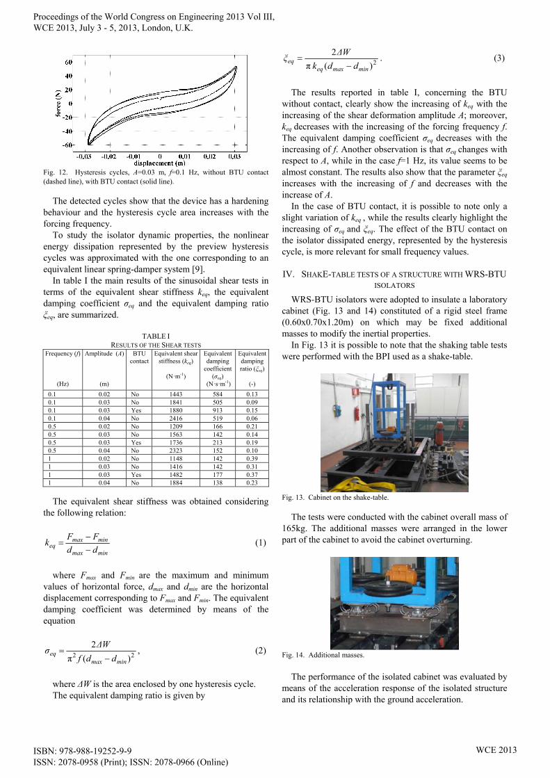
Fig. 12. Hysteresis cycles, A=0.03 m, f=0.1 Hz, without BTU contact (dashed line), with BTU contact (solid line).
The detected cycles show that the device has a hardening behaviour and the hysteresis cycle area increases with the forcing frequency.
To study the isolator dynamic properties, the nonlinear energy dissipation represented by the preview hysteresis cycles was approximated with the one corresponding to an equivalent linear spring-damper system [9].
In table I the main results of the sinusoidal shear tests in terms of the equivalent shear stiffness keq, the equivalent damping coefficient σeq and the equivalent damping ratio ξeq, are summarized.
TABLE I
RESULTS OF THE SHEAR TESTS Frequency (f)
(Hz)
Amplitude (A)
(m)
BTU contact
Equivalent shear stiffness (keq)
(N·m-1)
Equivalent damping
coefficient (σeq)
(N·s·m-1)
Equivalent damping ratio (ξeq)
(-)
0.1 0.02 No 1443 584 0.13 0.1 0.03 No 1841 505 0.09 0.1 0.03 Yes 1880 913 0.15 0.1 0.04 No 2416 519 0.06 0.5 0.02 No 1209 166 0.21 0.5 0.03 No 1563 142 0.14 0.5 0.03 Yes 1736 213 0.19 0.5 0.04 No 2323 152 0.10 1 0.02 No 1148 142 0.39 1 0.03 No 1416 142 0.31 1 0.03 Yes 1482 177 0.37 1 0.04 No 1884 138 0.23
The equivalent shear stiffness was obtained considering the following relation:
minmax
minmaxeq dd
FFk
(1)
where Fmax and Fmin are the maximum and minimum
values of horizontal force, dmax and dmin are the horizontal displacement corresponding to Fmax and Fmin. The equivalent damping coefficient was determined by means of the equation
22 )(π
2
minmaxeq
ddf
ΔWσ
, (2)
where ΔW is the area enclosed by one hysteresis cycle. The equivalent damping ratio is given by
2)( π
2
minmaxeqeq
ddk
ΔWξ
. (3)
The results reported in table I, concerning the BTU
without contact, clearly show the increasing of keq with the increasing of the shear deformation amplitude A; moreover, keq decreases with the increasing of the forcing frequency f. The equivalent damping coefficient σeq decreases with the increasing of f. Another observation is that σeq changes with respect to A, while in the case f=1 Hz, its value seems to be almost constant. The results also show that the parameter ξeq
increases with the increasing of f and decreases with the increase of A.
In the case of BTU contact, it is possible to note only a slight variation of keq , while the results clearly highlight the increasing of σeq and ξeq. The effect of the BTU contact on the isolator dissipated energy, represented by the hysteresis cycle, is more relevant for small frequency values.
IV. SHAKE-TABLE TESTS OF A STRUCTURE WITH WRS-BTU
ISOLATORS
WRS-BTU isolators were adopted to insulate a laboratory cabinet (Fig. 13 and 14) constituted of a rigid steel frame (0.60x0.70x1.20m) on which may be fixed additional masses to modify the inertial properties.
In Fig. 13 it is possible to note that the shaking table tests were performed with the BPI used as a shake-table.
Fig. 13. Cabinet on the shake-table.
The tests were conducted with the cabinet overall mass of 165kg. The additional masses were arranged in the lower part of the cabinet to avoid the cabinet overturning.
Fig. 14. Additional masses.
The performance of the isolated cabinet was evaluated by
means of the acceleration response of the isolated structure and its relationship with the ground acceleration.
Proceedings of the World Congress on Engineering 2013 Vol III, WCE 2013, July 3 - 5, 2013, London, U.K.
ISBN: 978-988-19252-9-9 ISSN: 2078-0958 (Print); ISSN: 2078-0966 (Online)
WCE 2013

Harmonic type excitations with different intensities were used to investigate the dynamic characteristics of the isolated cabinet. Furthermore, an earthquake record was used to evaluate the seismic behaviour of the cabinet in the presence of a realistic seismic excitation [10].
A. Dynamic characteristics
The tests were conducted for two different values of the amplitude (0.005 m and 0.010 m) and forcing frequency in the 0.5 – 5.0 Hz range.
Using two accelerometers, the accelerations of the platform and of the cabinet were detected and the two time histories were compared.
For each test, a frequency analysis of the two time histories (platform and cabinet accelerations) was performed and the amplitudes of the components, synchronous with that one, imposed to the platform, were compared; their ratio, reported as function of the forcing frequency (Fig. 15), shows that the cabinet acceleration is amplified in the neighbourhood of 1 Hz and that the system is isolated for forcing frequencies greater than about 1.5Hz;
An approximation of the isolated cabinet natural frequency can be easily obtained considering an equivalent linear mass-spring-damper system; hence, the cabinet was modelled as a single degree of freedom system with four linear spring-damper devices.
Since the shear tests have shown that it is not possible to find constant values of stiffness and damping for the considered system, the isolator equivalent shear stiffness adopted in the natural frequency calculation was chosen equal to the mean of the 12 values reported in table I.
Hz 02.1165
16954
14.32
14
2
1
m
kf
eqn (4)
where m is the cabinet mass. The value obtained in (4) is in agreement with the
experimental results reported in Fig. 15.
Fig. 15. Acceleration ratio vs. forcing frequency.
The dependence of the dynamic response of the isolated
cabinet on the intensity of the ground motion highlights the nonlinear property of the WRS-BTU isolator.
B. Earthquake responses
Fig. 16 shows the cabinet and the platform acceleration for an earthquake ground excitation (Friuli 1976). In this case, the overall mass of the cabinet was chosen equal to
185 kg. The isolation system reduces the acceleration transmitted
to the cabinet by 52 % over the ground acceleration.
Fig. 16. Comparison between the ground and the cabinet acceleration.
V. CONCLUSION
An experimental investigation of the performances of a WRS-BTU seismic isolator was presented. The proposed isolator is cheap and easy to realize by coupling a BTU with WRS springs; both the components are of normal industrial production and are already characterized by the manufacturers.
The tests on the WRS-BTU isolator were performed with a multi-purpose machine able to execute both shear tests on seismic isolators and shake-table tests on seismically isolated structures.
The results concerning the shear tests showed a nonlinear behaviour of the device. Moreover, shake-table experiments, conducted on a laboratory cabinet equipped with four WRS-BTU isolators, demonstrated their nonlinear dynamic characteristic and, at the same time, highlighted their good seismic isolation performance in terms of ground acceleration reduction.
REFERENCES [1] G. Di Massa, M. Migliaccio, S.Pagano, “A seismic insulator based on
wire rope spring and BTU,” 2nd European Conference on Tribology (ECOTRIB2009), Pisa, Italy, June 7-10, 2009.
[2] G. Di Massa, S. Pagano, E. Rocca, S. Strano, “Characterization of a seismic WRS-BTU insulation system”, XX AIMETA congress, ISBN: 9788890634017, Bologna, october 12-15, 2011.
[3] R. Brancati, S. Strano, F. Timpone, “An analytical model of dissipated viscous and hysteretic energy due to interaction forces in a pneumatic tire: Theory and experiments”, Mechanical Systems and Signal Processing , vol. 25, no. 7, pp. 2785 – 2795, 2011.
[4] M. Cardone, S. Strano, “Fluid-Dynamic Analysis of Earthquake Shaking Table Hydraulic Circuit” (ESDA2012-82422), in Proc. of the ASME 11th Biennial Conference on Engineering Systems Design and Analysis (ESDA2012), vol. 2, pp. 343 – 350, 2012.
[5] G. Di Massa, S. Pagano, E. Rocca, S. Strano, “Sensitive equipments on WRS-BTU isolators”, Meccanica, DOI: 10.1007/s11012-013-9708-9, 2013.
[6] S. Pagano, R. Russo, S. Strano, M. Terzo, “Modelling and Control of a Hydraulically Actuated Shaking Table Employed for Vibration Absorber Testing” (ESDA2012-82118), in Proc. of the ASME 11th Biennial Conference on Engineering Systems Design and Analysis (ESDA2012), vol. 1, pp. 651 – 660, 2012.
[7] S. Pagano, R. Russo, S. Strano, M. Terzo, “Non-linear modelling and optimal control of a hydraulically actuated seismic isolator test rig”, Mechanical Systems and Signal Processing, vol. 35, no. 1 – 2, pp. 255 – 278, 2013.
[8] S. Pagano, M. Russo, S. Strano, and M. Terzo, “A mixed approach for the control of a testing equipment employed for earthquake isolation systems,” Proceedings of the Institution of Mechanical Engineers,
Proceedings of the World Congress on Engineering 2013 Vol III, WCE 2013, July 3 - 5, 2013, London, U.K.
ISBN: 978-988-19252-9-9 ISSN: 2078-0958 (Print); ISSN: 2078-0966 (Online)
WCE 2013

Part C: Journal of Mechanical Engineering Science, DOI: 10.1177/0954406213484424, 2013.
[9] C. Onorii, M. Spizzuoco, A. Calabrese, G. Serino, “Applicability and reliability of innovative low-cost rubber isolators”, XIV ANIDIS congress, Bari, September 18-22, Italy, 2011.
[10] A. H. Muhr, G. Bergamo, “Shaking Table Tests On Rolling-Ball Rubber-Layer Isolation System”, in Proc. of the 14th European Conference on Earthquake Engineering, vol. 7, pp. 5703-5710, Ohrid, Republic of Macedonia, 30 August -3 September, 2010.
Proceedings of the World Congress on Engineering 2013 Vol III, WCE 2013, July 3 - 5, 2013, London, U.K.
ISBN: 978-988-19252-9-9 ISSN: 2078-0958 (Print); ISSN: 2078-0966 (Online)
WCE 2013