![REPORTOOCUM ETATIONPAOB - DTICcharacteristics of impinging jet sprays. Ingebo [6] quantified the drop-size distribution for heptane jets impinging at 90%, and obtained an empirical](https://static.fdocuments.us/doc/165x107/5f7eb6364693594f354d769d/reportoocum-etationpaob-dtic-characteristics-of-impinging-jet-sprays-ingebo-6.jpg)
Experimental Investigation of Impinging Diesel Sprays for HCCI Combustion
80
Experimental Investigation of Impinging Diesel Sprays for HCCI Combustion FREDRIK WÅHLIN Doctoral thesis Department of Machine Design Royal Institute of Technology S-100 44 Stockholm Trita-MMK-2006:17 ISSN-1400-1179 ISRN/KTHMMK/R-06/17-SE
Transcript of Experimental Investigation of Impinging Diesel Sprays for HCCI Combustion

Experimental Investigation of Impinging Diesel Sprays for
HCCI Combustion
FREDRIK WÅHLIN
Doctoral thesis Department of Machine Design Royal Institute of Technology S-100 44 Stockholm
Trita-MMK-2006:17
ISSN-1400-1179 ISRN/KTHMMK/R-06/17-SE

Trita-MMK-2006:17 ISSN-1400-1179 ISRN/KTHMMK/R-06/17-SE
Experimental Investigation of Impinging Diesel Sprays for HCCI Combustion
Fredrik Wåhlin
Doctoral thesis
Academic thesis, which with the approval of Kungliga Tekniska Högskolan, will be presented for public review in fulfilment of the requirements for a Doctorate of Engineering in Machine Design. The public review is held at Kungliga Tekniska Högskolan, Lindstedtsvägen 26 in room F3 at 14.00 on the 21th of February 2007.

i
ABSTRACT
Engine research and development is to a large extent driven by the quest of lowering
exhaust emissions and fuel consumption. The combination of low emissions and low
fuel consumption is not the simultaneous characteristic of the world’s primary
engine concepts, the diesel and the spark-ignited (SI) engine. However, such a
concept do exist, it is commonly called Homogeneous Charge Compression Ignition
(HCCI).
The HCCI combustion concept is when a premixed air and fuel mixture is ignited by
the heat of compression. The operation is unthrottled, like the diesel engine, which is
advantageous for its efficiency. The premixed air / fuel mixture preclude soot
formation, like the SI engine. An exclusive feature of HCCI combustion is
extremely low NOX production due to low-temperature combustion.
The mixture preparation of the typical gasoline HCCI engine is similar to the SI
engine, via port-injection, which results in a well homogenized mixture. Port
injection of diesel fuel is however very difficult since the environment is too cold for
the fuel to vaporise. A better alternative is therefore direct-injection. However,
injection must occur in a way where a homogeneous mixture is formed, while
contact of the liquid fuel with cold walls is avoided.
There are many approaches to direct-injected mixture formation. This thesis focuses
on exploring the concept of impinging sprays; its characteristics and its impact on
combustion and emissions. The work comprises unique information regarding
impinging sprays, as well as results regarding engine performance. It is concluded
that impinging sprays are well suited for early direct-injection.

ii
ACKNOWLEDGEMENTS
I acknowledge my dear wife Helena and our kids Anya and Joel for all the love and
joy. Thanks to my mother, father, brothers and family, I love you all. Thanks to all
my friends, who make my life interesting and fun. Thanks to Hans-Erik Ångström
for providing the possibility to do this work, and for all the powerful lab support.
Ernst Winklhofer for your ability to put things into perspective and keep the focus.
Andreas Cronhjort for invaluable numerical and experimental contributions. Lars
Dahlén for the enthusiasm and energy. Greger Juhlin for the support and for
employing me. Per Strålin as my buddy and for the special spray-humor. Per
Risberg for the conversations and friendship. Eric Lycke, Tommy Tillman and
Henrik Nilsson for their outstanding work in the lab. Uffe, Kurre and Lelle for their
job in the work shop. Big thanks to all the people at Scania and KTH who has been a
support to me.

iii
LIST OF PAPERS
The work is expressed in papers which were written by the author and co-authors.
The papers are appended in the end of the thesis. A summary of the papers and the
contribution of each author are found in the section “Work progress”.
Paper I. SAE 2004-01-1776.
“Fuel Sprays for Premixed Compression Ignited Combustion - Characteristics of
Impinging Sprays”, Fredrik Wåhlin and Andreas Cronhjort
Paper II. Applied Optics, vol. 43, No. 32, 2004.
“Segmentation Algorithm for Diesel Spray Image Analysis”, Andreas Cronhjort and
Fredrik Wåhlin.
Paper III. SAE 2004-01-2989.
“Effect of Injection Pressure and Engine Speed on Air/Fuel Mixing and Emissions
in a Pre-Mixed Compression Ignited (PCI) Engine using Diesel Fuel”, Fredrik
Wåhlin, Andreas Cronhjort, Hans-Erik Ångström and Ulf Olofsson.
Paper IV. (Accepted for publication at Atomization and Sprays, 2007).
“Impinging Diesel Sprays”, Fredrik Wåhlin and Andreas Cronhjort
Paper V. To be submitted. “HCCI Combustion with Impinging Diesel Sprays”, Fredrik Wåhlin.

iv

v
“No success in your career can compensate
for a failure in your private life”
Stephen R. Covey
“We must become the change we seek in the world”
Gandhi
“Self-Knowledge is best learned, not by contemplation,
but by action. Strive to do your duty and you will soon
discover of what stuff you are made.”
Johann Goethe
“You have lots of answers.
But what is the question?”
Ernst Winklhofer

vi

vii
TABLE OF CONTENTS
ABSTRACT .............................................................................................................. I
ACKNOWLEDGEMENTS .................................................................................... II
LIST OF PAPERS................................................................................................. III
BACKGROUND.......................................................................................................1
THE GLOBAL ENERGY SITUATION ...........................................................................1 The transport sector’s energy demand..............................................................2
EMISSIONS FROM GROUND TRANSPORTATION ........................................................2 Green house gases ............................................................................................3 Particulate matter (PM)....................................................................................4 Nitrogen Oxides (NOX) .....................................................................................4 Volatile organic compounds (VOCs) ................................................................4 Carbon monoxide (CO).....................................................................................5 Sulphur Oxides (SOX)........................................................................................5
INTRODUCTION ....................................................................................................7
POWER PLANTS FOR GROUND TRANSPORTATION ....................................................7 ENGINE COMBUSTION AND EMISSIONS FORMATION ................................................8
The SI engine.....................................................................................................8 The diesel engine.............................................................................................10 The HCCI engine ............................................................................................12 The HCCI combustion process........................................................................14 HCCI commercialized.....................................................................................16 Nissan MK-combustion ...................................................................................16 Honda AR Motorcycle Engine ........................................................................17 Toyota UNIBUS ..............................................................................................17
HCCI FUEL INJECTION CONCEPTS ..............................................................19
PORT INJECTED HCCI...........................................................................................19 GASOLINE DIRECT INJECTED HCCI.......................................................................19 DIRECT INJECTED DIESEL-HCCI ...........................................................................20
Early-injected diesel HCCI .............................................................................20 Impinging Sprays ............................................................................................22 Hollow-cone sprays ........................................................................................23 Standard diesel sprays ....................................................................................23 Late-injection diesel HCCI .............................................................................25 Comments........................................................................................................26
FUEL INJECTION AND SPRAYS ......................................................................27
SPRAY STRUCTURE AND BREAKUP........................................................................27 NOZZLE FLOW......................................................................................................29 SPRAY MACRO-SCALE CHARACTERISTICS.............................................................30

viii
Evaporating sprays .........................................................................................31 SURROUNDING FLOW FIELD - AIR ENTRAINMENT................................................33 IMPINGING SPRAYS ...............................................................................................35
High-velocity impinging sprays ......................................................................35
INVESTIGATING IMPINGING DIESEL SPRAYS..........................................39
EXPERIMENTAL EQUIPMENT.................................................................................39 WORK PROGRESS..................................................................................................43 PAPER I.................................................................................................................44 PAPER II ...............................................................................................................45 PAPER III ..............................................................................................................45 PAPER IV..............................................................................................................45 PAPER V ...............................................................................................................47 SUMMARY ............................................................................................................47
APPENDIX .............................................................................................................49
MODELLING THE ORIFICE COEFFICIENTS...............................................................49 DERIVATION OF THE SPRAY MODEL......................................................................55
ABBREVIATIONS.................................................................................................59
NOMENCLATURE ...............................................................................................61
REFERENCES .......................................................................................................63

Background
1
BACKGROUND
The following section covers some background on why it is important to control
emissions from vehicles.
The global energy situation The total global energy production increased by 40 % during 1980 – 2002. In 2002,
petroleum (crude oil and natural gas plant liquids) continued to be the world’s most
important primary energy source, accounting for 37.9 % of world primary energy
production [1]. Between 1992 and 2002, petroleum production increased by 13.3 %.
Coal ranked second as a primary energy source in 2002, accounting for 24.1 % (with
6.5 % increase since 1992), followed by dry natural gas at 23.5 % (with a 23.3 %
increase since 1992).
0
20
40
60
80
100
120
140
160
1978 1982 1986 1990 1994 1998 2002 2006
Year
Wo
rld
En
erg
y P
rod
uct
ion
[10
15 B
tu]
Petroleum
Coal
Dry natural gas
Net hydroelectric powerNet nuclear electric power
Net Geothermal, Solar, Wind, Wood and Waste Electric Power
Figure 1. World energy primary production trends [1].
Nuclear, hydro, and other (geothermal, solar, wind, wood and waste) electric power
generation ranked fourth, fifth, and sixth, as primary energy sources in 2002,
accounting for 6.63, 6.56, and 0.8 % of world primary energy production,
respectively. The global energy production is by over 90 % satisfied by limited

Experimental Investigation of Impinging Diesel Sprays for HCCI Combustion
2
natural resources, and the increasing demand is mainly covered with fossil fuels.
This scenario raises the question of how long the supplies will last. Whatever answer
one chooses to believe in, most will agree that finding new energy sources and
economizing the ones we have is very important in the long perspective.
The transport sector’s energy demand
The transport sector accounts for about 25 % of the total commercial energy
consumed worldwide, and consume approximately one-half of total oil produced,
and its proportion is increasing. The forecast is a considerable increasing demand of
transport services, as economic growth occurs in developing countries, incomes rise,
the trend toward urbanization continues and as the process of globalization moves
forward with expected increases in world trade. Up until 2020, demand is predicted
to grow by 3.6 % / year in developing countries and by 1.5 % / year in industrialized
countries [2]. The transport sector's current trend demands improvement of its
energy efficiency and development of new means and technologies that will reduce
the oil dependency [3].
Emissions from ground transportation The motorized transportation of today emits greenhouse gases, particulate matter,
nitrogen oxides, sulphur oxides and volatile organic compounds all of which have
negative impacts at local and often at regional levels [2]. However, exactly what
kinds of pollutants that are produced in what proportions varies significantly based
on a number of factors, including engine type, fuel used and driving conditions.
To deal with pollution from ground transportation, the legislated emission levels
have tightened over the years, and will so be continued. Table 1 shows the existing
and forthcoming legislated emission levels for heavy-duty trucks and buses in
Europe (Euro I –V) and the U.S. (EPA 07 - 10). The Euro VI is not set yet, but is
expected to be a significant reduction in oxides of nitrogen (NOX) and particulates
compared to Euro V.

Background
3
Table 1. Current and forthcoming legislated emission levels for Heavy-Duty Truck and Bus Engines [9].
Legislation Year NOx Particulates [g/kWh] [g/kWh]
Euro I 1992 8 0.25 Euro II 1996 7 0.15 Euro III 2000 5 0.1 Euro IV 2005 3.5 0.02 Euro V 2008 2 0.02 EPA 07-10, US 2007-2010 0.27 0.013
Green house gases
Statements are made that the global warming effect observed the latest 50 years only
can be explained if human emissions of greenhouse gases are taken into account [4].
If no proceedings are taken to limit the emissions of greenhouse gases, the earth’s
climate is expected to change with an unseen velocity, accompanying serious
consequences:
The CO2 concentration in the atmosphere will increase by 50 % – 160 %
until 2100, depending on what measures are taken.
The number of extreme weather phenomena will increase; rainstorms,
flooding, dry periods, fires etc.
Lack of fresh water will increase in certain regions.
Extinction of species and precious ecosystems: coral reefs, glaciers,
mangrove forests, polar and alpine regions.
Greenhouse gases, unlike many local air pollutants, are considered stock pollutants.
A stock air pollutant is one that has a long lifetime in the atmosphere, and therefore
can accumulate over time. Stock air pollutants are also generally well mixed in the
atmosphere. As a consequence of this mixing, the impact a greenhouse gas has on
the atmosphere is mostly independent of where it was emitted. These characteristics
of greenhouse gases imply that they should be addressed on a global (i.e.,
international) scale. Globally, transport accounts for about 21 % of CO2 emissions.
To lower this number, more fuel efficient vehicles and alternative fuels are required.

Experimental Investigation of Impinging Diesel Sprays for HCCI Combustion
4
Particulate matter (PM)
Particulate matter is perhaps the most critical transport-sector pollutant for
developing countries in the early part of the twenty-first century. Its effects on
human health are significant while technical mechanisms to control particulate
matter are costly. Current regulations of PM are by mass, although there is
increasing evidence that smaller particles causes more damage to human health than
large particles [5]. Also, there is little attention paid to the actual chemical
composition (including the proportion of soot, sulphates and polycyclic aromatic
hydrocarbons [PAH]) of PM. However, speculations are that the extent of health
side effects depends on this composition.
Nitrogen Oxides (NOX)
NOX are of concern both because of their direct effects on human health, and
because they react in the atmosphere with volatile organic compounds (VOCs) to
produce photochemical smog. Photochemical smog comprises mixtures of PM and
noxious gases and is formed when NOX and VOCs react in the presence of heat and
sunlight [6]. Nitric oxide (NO) and nitrogen dioxide (NO2) are released in
combustion because the molecular nitrogen (N2) in the air/fuel mixture splits and is
oxidized. The higher the flame temperature or longer the residence time, the more
NOX production; consequently, the same technical interventions in engine
calibration that might reduce VOCs will increase NOX. NOX is also a contributor to
acid rain and the global warming. In addition, it is toxic and can cause impairing
respiratory function and damage to lung tissue [7].
Volatile organic compounds (VOCs)
The term volatile organic compounds refer to a range of non-methane hydrocarbons
(NMHCs) which evaporate at normal ambient temperatures. NMHCs are released
during combustion due to incomplete combustion of the fuel. VOCs are usually
regulated as a class because of their contribution to ground-level ozone formation
through a photochemic smog process. Ozone is hazardous to human health as well
as to plants [8]. It seems to impair respiratory function as a short-run response to
exposure, but the longer-term effects are less clear. The production of ground-level
ozone occurs through reactions in sunlight of VOCs and NOX. VOCs also contribute
to particulate formation by coagulating onto soot. In addition, some VOCs are
themselves hazardous to human health; they include benzene, polycyclic aromatic

Background
5
hydrocarbons, 1.3-butadiene, aldehydes and, through groundwater seepage, methyl
tertiary butyl ether (MTBE).
Carbon monoxide (CO)
CO emissions are often highly correlated with hydrocarbon (HC) emissions. In the
human body, CO can cause oxygen deprivation (hypoxia), displacing oxygen in
bonding with hemoglobin, causing cardiovascular and coronary problems,
increasing risk of stroke, and impairing learning ability, dexterity and sleep [2]. CO
is mostly hazardous in relatively confined areas such as tunnels under bridges and
overpasses, and in dense urban settings. In unconfined areas or away from
population centres, it will stabilize into CO2 before damage to human health is
likely.
Sulphur Oxides (SOX)
Sulphur present in fuel will be released either as sulphates (SO42-) (which can be an
important component of PM) or sulphur dioxide (SO2). SO2 is a major health
concern because of its effects on bronchial function, but in metropolitan regions
with high concentrations of ambient SO2, the contribution of the transport sector
tends to be secondary to that of manufacturing and/or electricity production. For this
reason, concern about sulphur in transport fuels tends to be driven more out of
concern about particulates rather than SO2. Fuels for ground transportation will be
regulated to very low sulphur concentrations; to protect aftertreatment equipment
and lower the particulate emissions.


Introduction
7
INTRODUCTION
This chapter provides some introduction to diesel, SI and HCCI combustion
concepts and their advantages and disadvantages.
Power plants for ground transportation The two engine types that dominate today’s motorized ground transportation are the
diesel engine and the SI engine. The diesel engine offers superior fuel consumption
compared to the SI engine. The diesel engine ranges in sizes from powering the
largest ocean-crossing super tanker to the smallest private car, and is the
predominant power plant for heavy-duty transportation where fuel efficiency is a
high priority. Unfortunately, the diesel engine emits high levels of nitric oxides
(NOX) and particulate matter (PM) compared to the catalyst-equipped SI engine, see
Figure 2. To cope with future emissions legislation, exhaust aftertreatment devices
such as diesel particulate filters (DPF), lean NOX traps (LNT) and urea-based
selective catalyst reduction (SCR), will most probably be required.
Figure 2. Severe smoke emissions from a diesel engine. In this case the smoke emissions are unacceptable; smoke emissions from a modern diesel engine are invisible.
The catalyst-equipped SI engine is popular for private cars and has very low
emissions, but it is not problem-free. Its emissions are severe under cold-start

Experimental Investigation of Impinging Diesel Sprays for HCCI Combustion
8
conditions, and its low efficiency (high fuel consumption) makes it a large producer
of CO2.
Engine manufacturers are forced to mobilize considerable effort and resources to
find a solution that copes with the increasingly stringent emission levels. There are
several possible technical paths this may take. However, if an engine manufacturer
were able to achieve the legislated emission levels without exhaust aftertreatment,
then they may have an advantage due to the following [10]:
lower cost system
improved engine and component durability
reduced packaging concerns
enhanced image as a technology leader
product distinction in a crowded marketplace
A combustion concept with the potential to fulfil on this is HCCI. HCCI combustion
could roughly be described as a hybrid with the best features from the diesel engine
and the SI engine. Its NOX and smoke emissions are very low, while its efficiency is
high, comparable with the diesel engine.
Engine combustion and emissions formation This section consists of a brief description of combustion and emissions formation
of SI, diesel and HCCI. The SI and diesel sections originate from ref. [11] if not
otherwise stated.
The SI engine
The SI engine relies on a stoichiometric fuel/air mixture and a sparkplug for its
ignition. Typically, the compression ratio lies around 10:1. Modern SI engines are
usually port-injected; the fuel is injected through a low pressure system into the
intake manifold. Its low boiling range (25 - 210 °C) [12] makes most of the gasoline
to evaporate and mix with the air. The fuel/air mixture is then inhaled via the intake
port into the cylinder during the intake stroke and compressed during the
compression stroke. The fuel and air continues to mix throughout this process and at
the end of the compression stroke, the mixture is ignited by a spark. A close-to-
stoichiometric condition is required for two reasons: To enable for spark ignition
and for the performance of the three-way catalyst. A flame kernel is initiated by the
spark well before top dead centre (TDC). The mixture motion and composition

Introduction
9
around the spark plug at time of spark discharge is decisive for the flame
development and subsequent flame propagation. The small flame kernel initiated by
the spark grows as the turbulent flame front propagates through the combustion
chamber, see Figure 3.
Figure 3. Spark ignited combustion images [13]. Each flame image captured from consecutive cycle. The flame can be described as premixed turbulent.
The temperature in the reaction front is well above the NOX formation limit. The
burned gases in the centre of the combustion chamber are compressed to the highest
temperature attained in the cylinder as the rest of the charge burns, causing
considerable NOX formation. The absence of luminous yellow flames indicates a
well pre-mixed mixture and hence no soot formation. The unburned mixture ahead
of the propagating flame front is also compressed, and some part of it enters crevices
around the top-land region and leaks past the piston ring into the crank case as blow-
by gases. As the flame front is extinguished at the cold combustion chamber walls,
the mixture in the crevices remains unburned. Some of the mixture in the crevices
flows back into the combustion chamber as the pressure drops in the expansion
stroke. The lower temperature in the expansion stroke will not oxidize all the fuel
and some of it will remain as HC and CO emissions. The unhealthy mixture of CO2,
NOX, HC and CO in the cylinder is now dispatched into the exhaust system where
most of it is converted to N2, CO2 and H2O by the three-way catalyst. However,
during cold start conditions the catalyst temperature is lower than its light-off

Experimental Investigation of Impinging Diesel Sprays for HCCI Combustion
10
temperature (~300 °C), and the pollutants are released into the atmosphere. The
catalyst temperature needs to be ~400 °C or more for a high conversion rate [12].
The efficiency of the SI engine is limited mainly for two reasons. Firstly, since it
requires a stoichiometric charge, it is necessary to throttle the intake for lowering the
load, which means losses and deteriorating efficiency. Secondly, to avoid knocking
(which is actually HCCI combustion), a low compression ratio is required which
lowers the overall efficiency. The reason to avoid HCCI in this case is because the
reaction rate is much too fast at stoichiometric conditions. The rapid heat release
causes violent oscillations that can destroy the combustion chamber. Knocking
combustion also stirs up the thermal boundary layer and exposes the piston to higher
temperatures, which can result in piston melting.
The diesel engine
In the modern direct-injected diesel engine, fuel is injected into compressed gas at
TDC via a high pressure injection system. The compression ratio in the diesel engine
is high, usually around 18:1, resulting in a high in-cylinder gas temperature and
density at TDC, approximately in the range of 1000 K and 30 kg/m3 for a
turbocharged engine at high load. The highly pressurized fuel is introduced into the
combustion chamber via 5-8 fuel sprays, depending on the size of the cylinder. The
fuel sprays break up, atomize, evaporate and mix with the high density high-
temperature gas, which creates a combustible mixture. After an ignition delay of a
few crank angle degrees (CAD), fuel which has mixed with air ignites, creating a
rapid heat release. The combustion after the pre-mixed part is mixing controlled; the
rate of heat release is controlled by how fast the fuel will atomize, evaporate and
mix with air thus creating a combustible mixture. This mixing-controlled
combustion can be described as a turbulent unsteady diffusion flame. The yellow
luminosity of the flames originates from hot radiating soot particles, see Figure 4.
Since the combustion is mixing controlled there is no knocking limit, hence the
higher compression ratio and subsequent higher efficiency. To ensure a complete
combustion, the diesel engine always operates in a globally lean condition. This
enables unthrottled operation which is also good for the engine efficiency. However
using a three-way catalyst is impossible. In-cylinder air swirl helps the transport of
oxygen to the combustion zone and speeds up the heat release rate. After end of
injection, the air swirl is mainly responsible for the continuing mixing between fuel
and oxygen, thus promoting a complete combustion. Various techniques can be used

Introduction
11
to lower NOX and PM emissions from the diesel engine. Unfortunately, lowering
one usually results in raising the other.
0 CAD 1 CAD 2 CAD
3 CAD 4 CAD 5 CAD
Figure 4. Diesel combustion images on courtesy of Andreas Cronhjort. A crankangle-resolved sequence of 8 burning diesel sprays. The yellow luminosity of the flames originates from hot radiating soot particles.
Figure 5 shows a schematic of the conceptual model of direct-injected (DI) diesel
combustion by Dec [14], during the mixing-controlled burn, prior to end of
injection.
Figure 5. A schematic showing the conceptual model by Dec of DI diesel combustion during the mixing-controlled burn [14].

Experimental Investigation of Impinging Diesel Sprays for HCCI Combustion
12
A short distance downstream of the injector tip, the fuel vapour and entrained air has
formed a relatively uniform mixture. Then soot appears as small particles across the
entire cross-section of the jet. The soot formation and particle growth continue as the
soot moves down to the head vortex. The soot particles accumulate in the
recirculating head vortex where they have time to grow to a larger size. Some of the
soot particles reach the diffusion flame at the periphery of the jet where they can be
oxidized by OH radicals. When the exhaust port opens, most of the particles are
already oxidized.
The initial soot formation is most likely formed in a standing fuel-rich premixed
flame where local air/fuel ratio typically is around 0.25. Adiabatic flame
temperatures are typically ~ 1600 K which is below the thermal NOX formation
limit. The presence of this standing premixed flame throughout the mixing
controlled burn would mean that all the fuel first undergoes fuel-rich premixed
combustion and later diffusion-flame combustion, rather than being a more classical
pure fuel/air diffusion flame. The diffusion-flame combustion occurs at the jet
periphery. The locally stoichiometric condition results in a high flame temperature,
while excessive oxygen is available. This is a favourable condition for thermal NO
formation. Soot oxidation occurs via OH radicals attack at the diffusion flame. OH
radical attack is thought to be the primary method of soot oxidation [14].
The HCCI engine
It is said that a loved child has many names, and the HCCI-infant is no exception.
Johansson [15] has summarized many of the invented acronyms for this type of
combustion and associated author, institute and year, see Table 2.

Introduction
13
Table 2. HCCI Acronyms (from [15]). Acronym Meaning Author Location Year
ATAC Active Thermo-Athmosphere Combustion
Onishi Nippon clean engine research institute
1979
TS Toyota-Soken combustion Nogushi Toyota/Soken 1979
CIHC Compression-Ignited Homogeneous Charge
Najt Univ. Wisconsin-Madison
1983
HCCI Homogeneous Charge Compression Ignition
Thring SwRI 1989
Selbstzündning Stockinger Univ. Hamburg 1992
AR, ARC Active Radical Combustion Ishibashi Honda 1996
FDCCP Fluid Dynamically Controlled Combustion Process
Duret IFP Institute Français du Pétrole
1996
PCCI Premixed Charge Compression Ignition Aoyama Toyota 1996
MK, M-fire Modulated Kinetics Kawashima Nissan 1997
PREDIC Premixed Diesel Combustion Tsujimura et al. New ACE 1996
MULDIC Multiple Stage Diesel Combustion Tsujimura et al. New ACE 1998
HIMICS Homogeneous Charge intelligent Multiple Injection Combustion System
Yokota et al. Hino Motors 1997
HCDC Homogeneous Charge Diesel Combustion
Suziki et al. Traffic Safety and Nuisance Research Institute
1997
UNIBUS Uniform Bulky Combustion System Yanagihara Toyota 1997
HC Homogeneous Combustion Willand Daimler-Benz 1998
SPAC Space Combustion ? Daimler-Benz 1998
RZV Raumverzündning ? Daimler-Benz 1998
CAI Controlled Autoignition ? IFP 1998
PCI Premixed Compression-Ignited combustion
Iwabushi Mitsubishi 1999
Although it exist differences between the concepts listed in Table 2, what they all
have in common is that they rely on a pre-mixed charge, which is ignited with the
heat of compression. A diluted mixture (usually recirculated exhaust gases (EGR)
and/or air) is used in the HCCI engine to suppress the otherwise too rapid heat
release (knocking) and to decrease or eliminate NOX formation. Since the HCCI
engine operates in diluted mode it enables for unthrottled operation (as the diesel
engine), which eliminates the gas-exchange losses associated with gasoline engine.
Moreover, a high compression ratio, low heat transfer rate and rapid heat release
provides the HCCI engine with high diesel-like efficiency. Major problems and
disadvantages with the HCCI engine are:
Controlling the combustion phasing.
High peak pressures and rapid heat releases limits the practical power
density of the engine.

Experimental Investigation of Impinging Diesel Sprays for HCCI Combustion
14
High amounts of HC and CO emissions due to “cold” combustion.
In addition, HCCI with diesel fuel has two important problems: the low resistance to
autoignition and the preparation of the in-cylinder air/fuel mixture. These problems
are discussed under the section HCCI Fuel Injection Concepts.
The HCCI combustion process
As its name indicates, Homogeneous Charge Compression Ignition relies on the
compression ignited combustion of a “homogeneous” charge. The term
“homogeneous” is however somewhat misleading since there are always
heterogeneities in the mixture, especially in direct injected HCCI but also when
using a customary port injection system. Measurements using fuel planar laser
induced fluorescence (PLIF) reveals inhomogeneities with a scale of roughly 4 to 6
mm using port-injection, however there is no significant difference on the
combustion process to a fully homogeneous mixture [16].
The HCCI combustion process is fundamentally different from the SI and diesel
combustion process. The ignition occurs at seemingly arbitrary points
simultaneously in the combustion chamber [17], [18], see Figure 6. The heat release
in the HCCI engine occurs throughout the bulk of the charge, as can be seen in a
conceptual model proposed by Onishi [19] in 1979, see Figure 7.
Figure 6. HCCI combustion images [13]. Ignition occurs at several points simultaneously. (On courtesy of E. Winklhofer).
Introduction
15
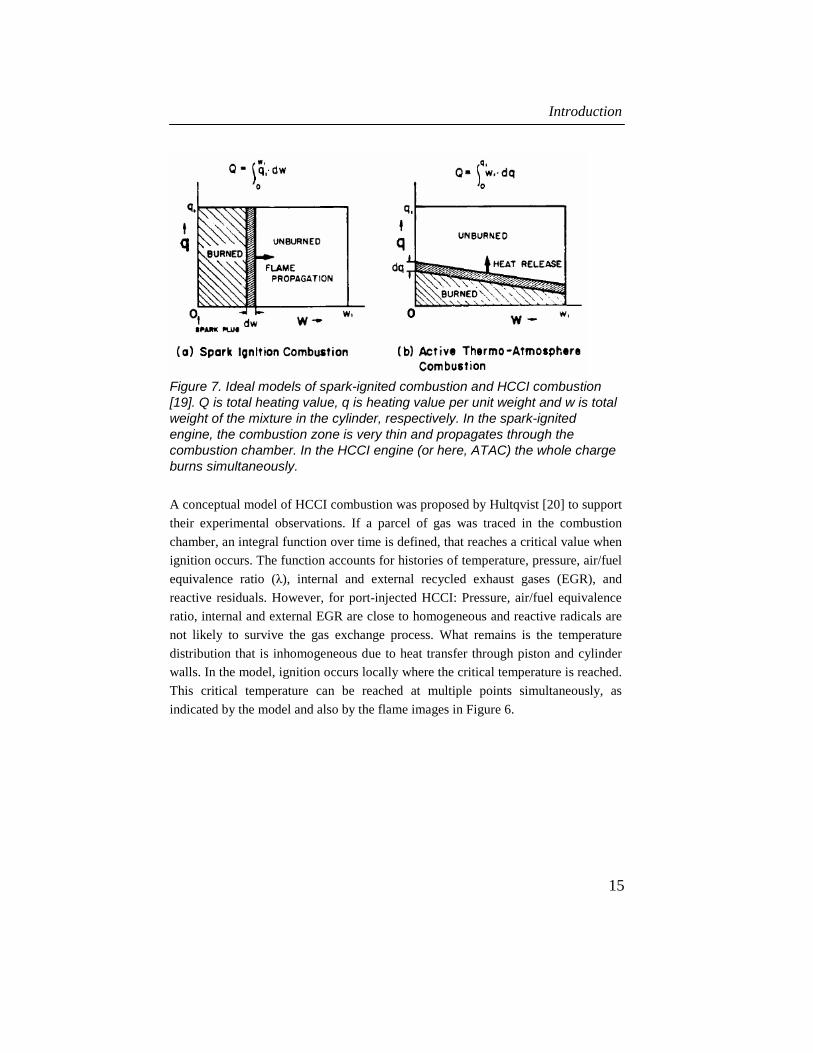
Figure 7. Ideal models of spark-ignited combustion and HCCI combustion [19]. Q is total heating value, q is heating value per unit weight and w is total weight of the mixture in the cylinder, respectively. In the spark-ignited engine, the combustion zone is very thin and propagates through the combustion chamber. In the HCCI engine (or here, ATAC) the whole charge burns simultaneously.
A conceptual model of HCCI combustion was proposed by Hultqvist [20] to support
their experimental observations. If a parcel of gas was traced in the combustion
chamber, an integral function over time is defined, that reaches a critical value when
ignition occurs. The function accounts for histories of temperature, pressure, air/fuel
equivalence ratio (λ), internal and external recycled exhaust gases (EGR), and
reactive residuals. However, for port-injected HCCI: Pressure, air/fuel equivalence
ratio, internal and external EGR are close to homogeneous and reactive radicals are
not likely to survive the gas exchange process. What remains is the temperature
distribution that is inhomogeneous due to heat transfer through piston and cylinder
walls. In the model, ignition occurs locally where the critical temperature is reached.
This critical temperature can be reached at multiple points simultaneously, as
indicated by the model and also by the flame images in Figure 6.

Experimental Investigation of Impinging Diesel Sprays for HCCI Combustion
16
Figure 8. A conceptual model of HCCI combustion [20]. The model comprises a varying temperature field. Other scalars are considered homogeneously distributed.
However for direct-injected HCCI combustion, the λ distribution is not considered
homogeneous. In this case, zones with a closer to stoichiometric mixture will
contribute to an earlier ignition. This mechanism is directly related to the
combustion control possibilities associated with variable injection timing, since the
injection timing defines the λ stratification at start of combustion (SOC).
HCCI commercialized
There are three commercial vehicle engines that use some form of premixed
combustion during a portion of their operating range. A light truck engine by Nissan
that uses MK-combustion with diesel fuel at light load, a 2-stroke motorcycle
gasoline engine by Honda partially running in HCCI-mode, and a diesel engine by
Toyota which is working with a combination of early and late injection timings at
low load and speed.
Nissan MK-combustion
The Nissan MK-combustion system (also called M-fire) [21] is based on a standard
diesel engine. The engine was brought into production in 1998 for the Japanese
market. The engine runs in MK mode at low load and switches to regular diesel
operation at high loads. A high swirl ratio is employed when operating in MK mode,
as well as a high EGR level and retarded injection timing to prolong the ignition
delay. With this approach it is possible to achieve a longer ignition delay than the

Introduction
17
injection duration, hence providing time for the fuel to mix with air before
combustion. The pre-mixed combustion results in very low NOX and particulate
matter emissions.
Honda AR Motorcycle Engine
The Honda Active Radical (AR) engine [22] is a 2-stroke single-cylinder engine that
operates at spark-ignition mode at high loads, idle, and for cold-starts. Transition to
HCCI combustion occurs at low load. The engine has a low (6.1:1) trapped
compression ratio, and HCCI operation is obtained by throttling the exhaust. With
exhaust throttling, the engine operates with a high fraction of hot residual gases,
which is enough to obtain HCCI combustion, even at this very low compression
ratio. Exhaust throttling is decreased as the load increases, until finally the residual
fraction is too low to keep the engine operating in HCCI mode, where the engine
switches to spark-ignition mode. The performance map has a "transition region"
where the engine can operate in both HCCI mode and SI mode. The AR engine has
demonstrated considerable advantages in fuel economy; at 50 km/h cruising speed
the fuel economy improved 57 %, with a simultaneous 65 % reduction in HC
emission.
Toyota UNIBUS
The Toyota UNIBUS comprises a combination of early and late injection timing.
The operation regime is up to half load and speed. The concept is described by
Hasegawa and Yanagihara [23]. The early injected fuel undergoes a low-
temperature reaction while the late injection serves as an ignition trigger and sets off
the high temperature reaction. The first injection quantity was small, 5 to 15 mm3.
The concept is known as UNIBUS (Uniform bulky combustion) and was applied to
the production engine (1KD-FTV, 3-liter 4-cylinder) in August 2000 on the
Japanese market.


HCCI Fuel Injection Concepts
19
HCCI FUEL INJECTION CONCEPTS
The two main fuel injection concepts for HCCI are port injection (PI) and direct
injection (DI). Port injection works with volatile fuels (like gasoline) while direct
injection is more suitable for heavy fuels (like diesel).
Port injected HCCI A common way to premix fuel with air in an engine is to use a port injection system,
which is simple, cheap and creates a well-mixed mixture [16]. This approach is
appropriate when running HCCI combustion on gasoline and numerous studies of
HCCI have been conducted using this configuration. A limitation for port injected
gasoline HCCI is on very low load, when the combustion temperature falls under a
critical value (1400-1500 K for speeds typical for heavy-duty truck engines) and
large amounts of HC and CO are formed, thus depleting the combustion efficiency
[27]. Another drawback is the wall film in the intake system that is rather slow
reacting to engine transients and could possibly obstruct the combustion control
when using variable valve timing (VVT). Port injection with diesel fuel has
additionally difficulties since its higher boiling range (200 – 300°C for Swedish
MK1) results in poor evaporation. The non-evaporated fuel will adhere in the intake
system and on the combustion chamber walls, which dramatically increases the
smoke and HC emission and dilutes the lubricating oil [16], [30], [31]. Raising the
intake temperature minimizes the fuel wall-film in the intake system and reduces the
HC emission, even if this still is on a high level [16], [30], [32]. Furthermore, raised
intake temperature reduces power density and advances the combustion timing of
the engine. This is a drawback since the HCCI engine suffers from low power
density. The diesel-HCCI engine needs a very low compression ratio to delay the
ignition timing, which is bad for the efficiency. Therefore it is not a good idea to
further advance the ignition timing with a raised intake temperature.
Gasoline direct injected HCCI Although port injection works for gasoline-HCCI, several investigations
demonstrate the advantage of using a gasoline direct injection (GDI) system [24]-
[29]. The possibility of stratifying the air/fuel charge with late direct-injection will
increase the local combustion temperature. This results in decreasing HC and CO
emissions, hence increasing combustion efficiency at lower loads. It also offers a

Experimental Investigation of Impinging Diesel Sprays for HCCI Combustion
20
limited possibility of phasing the combustion timing with the injection timing. A
drawback with a GDI system is higher cost.
Direct injected diesel-HCCI Direct injection eliminates the need for a raised intake temperature, since injection
can occur at elevated temperatures in the compressed in-cylinder gases. The task of
the injection process is to create a sufficiently premixed mixture before ignition
occurs. A sufficiently premixed mixture can be defined as one which creates low
NOX and smoke. Also, it is desirable to keep CO and HC emissions as low as
possible, even though these emissions are a natural consequence of low-temperature
premixed combustion. An equally important task for the injection strategy is
avoiding fuel adhering or condensing to the cylinder walls. A key parameter is to
control the fuel penetration length, i.e. avoid any contact of liquid fuel with the
cylinder and combustion chamber walls. Direct-injected diesel HCCI can be divided
into two areas, early injection (early under the compression stroke) and late injection
(usually after TDC).
Early-injected diesel HCCI
A certain time is always needed for the process of fuel injection and mixture
homogenization. The consequence is advanced injection timings for early-injection
diesel HCCI combustion. Early injection timings mean lower gas temperature and
density in the cylinder, which will reduce fuel vaporization rate and enhance the
liquid penetration length. On the other hand, “later” early injection timing means
higher gas densities and eventually vaporizing conditions, which will lower the
liquid penetration length and reduce the risk for wall wetting. Also, the rate of
entraining gas mass into the spray is higher at late injection timings, which creates a
leaner spray that mixes faster to globally lean conditions [33]. This situation is
illustrated in Figure 9. A potential of reduced HC and CO emissions is also
accompanied with late injection timings due to the potential of less fuel in the squish
region [34]. Shorter residence time for the fuel in the combustion chamber before
combustion reduces the risk of fuel condensation on cold surfaces. However,
drawbacks with later injection timings are shorter mixing time before combustion
which causes a need of a more advanced high-pressure injection system which can
provide the high-momentum sprays which are needed for a high mixing rate.

HCCI Fuel Injection Concepts
21
-160 -140 -120 -100 -80 -60 -40 -20 0 20 40 600
5
10
15
20
0
100
200
300
400
500
600
Gas density [kg/m3]
"Late" Injection regime- Short mixing time- High density −> Short penetration- High temperature −> Short liquid penetration
Gas
den
sity
[kg/
m3 ]
Gas
tem
pera
ture
[°C
]
Crank Angle Degrees [CAD]
DieselEvaporates
"Early" Injection regime- Long mixing time- Low density −> long penetration- Low temperature −> long liquid penetration
Gas temperature [°C]
Figure 9. In-cylinder gas density and temperature with late and early injection regimes.
When injection timing is advanced, the ignition delay becomes longer and the
mixture becomes more homogeneous before combustion. Emissions formation from
“late” early-injection combustion was studied by Musculus [35]. The operating
conditions were low-temperature combustion, where injection was completed just
before main heat-release. The results indicate that NO formation occurs throughout
the jet, rather than being formed near a thin diffusion flame on the jet periphery, as
in conventional diesel combustion. Liquid fuel penetration lengths were in this case
found to be approximately twice as long as for conventional diesel combustion. Soot
is formed in the fuel-rich head vortex that is formed after impingement, where the
mixing rate is slow. This is illustrated in Figure 10.

Experimental Investigation of Impinging Diesel Sprays for HCCI Combustion
22
Figure 10. Left: Schematic representation of the features in the jet cross-section of the extension of the conceptual model of diesel combustion to low-load, early-injection, low temperature conditions (from [35]). Right: Example of the operating conditions.
Main goals of DI-diesel HCCI research are reduced cylinder wall wetting and
increased evaporation and mixing of the spray. Charge stratification should be
achieved to avoid low temperature combustion near walls and to enhance load
stability [36]. Different strategies have been tested for early-injection mixture
formation. These can roughly be divided in hollow-cone sprays, impinging sprays
and ordinary diesel sprays – often in combination with a narrow included angle
(definition in Figure 17), and/or multiple injections.
Impinging Sprays
Takeda et al. [37] tested a system for early injection consisting of two side-mounted
injectors, where the sprays impinged in the centre of the combustion chamber. Very
low NOX emissions were found for this premixed combustion type, however HC and
CO were high. A small effect of swirl ratio on emissions was found. The load could
be increased by adding a late injection to the early injection (Hashizume et al. [38]),
but this was paid for with increased NOX and smoke. Akagawa et al. [39] found that
the mixing process of the side-mounted impinging injectors resulted in significant
wall-impingement. Split-injection could reduce the HC and CO emissions, however
paying with an increase of NOX (Nishijima et al. [40])
Iwabuchi et al. [41] improved the mixing characteristics using a novel impinging-
spray nozzle, where the fuel from two injector holes impinged at their orifice exit.
The sprays from this nozzle were found to have large cone angles and low
penetration rates. Combustion studies with this nozzle resulted in a significant
reduction in fuel consumption and emissions compared to the conventional single
hole nozzle.

HCCI Fuel Injection Concepts
23
Impinging-spray nozzles and nozzles with narrow included angles were tested by
Nordgren et al. [42]. Low NOX was achieved with all nozzles, however lowest HC
emissions were obtained with the impinging-spray nozzles.
Hollow-cone sprays
Harada et al. [43] tried fully premixed combustion using swirling-flow pintle-
nozzles. One of the pintle-nozzles provided a more uniform mixture than the others.
HC and CO emissions were improved compared to a micro-hole nozzle. Akagawa et
al. [39] concluded that major sources to HC and CO were adhesion of fuel to the
cylinder line and flame quenching by the cylinder liner or combustion chamber
walls. Adhesion of fuel could be reduced using a pintle-nozzle with swirl grooves.
Reducing the topland crevice volume significantly reduced HC.
A hollow-cone spray in conjunction with a deep-bowl combustion chamber was
tested by Ishima et al. [44]. The operation regime was low load, up to 0.35 MPa
indicated mean effective pressure (IMEP). The fuel consumption was generally
high, presumably due to bad combustion efficiency.
A low penetrating hollow cone spray was tested for premixed diesel combustion
by Ra et al. [45]. Injection timing had to be very early to avoid NOX formation. High
CO emissions were observed for all injection timings. The main cause was identified
as wall wetting.
Standard diesel sprays
Takeda et al. [37] tested three different types of nozzles for early injection. One
standard six-hole nozzle, one sixteen-hole nozzle with reduced hole diameter and
one 30-hole nozzle with reduced hole diameter and three different included angles.
The nozzle that had best fuel consumption in combination with low NOX was the
30-hole nozzle; however, HC and CO emissions were still high. Small variations in
emissions with injection pressure were found. The same 30-hole nozzle was later
tested by Harada et al. [43], and it was found to significantly over-penetrate.
The problem of fuel wall impingement was recognized by Iwabuchi et al. [41].
Nozzles of different included angles were tested to minimize the wall wetting. A
minimum of wall-impingement was found with 80° included angle.
The approach of a small included spray angle was also tested by Gatellier et al.
[46]. In combination with a deep bowl combustion chamber, it could operate at high
load using conventional diesel combustion, and at lower load using HCCI
combustion. HCCI fuel consumption was high in some cases due to high HC and

Experimental Investigation of Impinging Diesel Sprays for HCCI Combustion
24
CO emissions. Good fuel consumption with HCCI combustion could be achieved up
to 0.9 MPa IMEP.
Shimazaki et al. [47] performed premixed diesel combustion using a narrow
included-angle nozzle. The injection timing was late in the compression stroke near
TDC. The strategy was based on high-pressure late injection into high temperature –
which promotes the turbulent mixing rate and reduces the risk of wall wetting. CFD-
simulations indicated that the low HC emissions observed at the late injection
timings are due to reduced fuel in the squish area. The smoke emission appeared
related to the duration between end of injection (EOI) and ignition. The authors
suggest a dual-mode operation with conventional diesel combustion at high load.
The examined premixed diesel operation regime was at very low load.
A combination of early and late injection timings was investigated by Hasegawa
and Yanagihara [23]. The early injected fuel undergoes a low-temperature reaction
while the late injection serves as an ignition trigger and sets off the high temperature
reaction. The first injected quantity was small, 5 to 15 mm3.
A very narrow (60°) included-angle nozzle in combination with multiple
injections was tested by Helmantel and Denbratt [48]. 0.9 MPa IMEP was achieved
with a low compression ratio and high EGR levels. Combustion efficiency based on
HC and CO ranged from 86 % at low load to 94 % at high load. However, ordinary
diesel operation with the narrow included angle resulted in high fuel consumption
and smoke emissions, despite modifications to the combustion chamber (Helmantel
et al. [49]). The 60° nozzle was therefore replaced with a 140° nozzle, which
improved combustion efficiency. HCCI operation with the 140° nozzle was
successful using multiple injections; however the tested load in this case was only
0.3 MPa IMEP.
A study on injection parameters such as included angle, injection timing, number
of injections and injection pressure was made by Buchwald et al. [50]. Low fuel
consumption was found with the combination of either:
Large included spray angle, low injection pressure, many injections, late
injection timing.
Small included spray angle, high injection pressure, few injections, early
injection timing.
The possibility to operate with a large included spray angle is advantageous for
conventional diesel operation at high load. However; the investigation was

HCCI Fuel Injection Concepts
25
performed at low load, IMEP was 0.33 MPa. Expanding the load range with
premixed diesel combustion using a large included angle may be difficult due to
wall wetting.
An optical study of premixed diesel combustion was made by Kanda et al. [51].
The first experimental setup had a narrow included angle nozzle in combination with
a shallow bowl combustion chamber. The other setup was large included angle
nozzle with a re-entrant bowl. Fuel impingement onto the piston at early injection
timings was identified as a source of HC, CO and soot.
Premixed-charge compression-ignition (PCCI) diesel combustion was investigated
by Hardy and Reitz [52], using high EGR levels. A narrow included angle nozzle
was used. Equivalence ratios of up to 0.94 were tested. High HC emission was
observed at this high equivalence ratio. CO emissions were high at low load. Piston
impingement was thought to be the reason for high HC and fuel consumption.
Different nozzle included angles were tested by Lee and Reitz [53]. An attempt to
optimize the spray targeting in the bowl was made. Testing conditions were low load
and high EGR levels. It seemed be a correlation between low soot emissions and
spray targeting to the piston bowl edge near the squish region, regardless of included
angle. However, all the details of the mixing process are not clear from the results.
Late-injection diesel HCCI
Late-injection diesel HCCI is commonly referred to as MK-combustion, after the
combustion concept by Nissan [54] - [56]. A huge advantage with the concept is that
the combustion timing can be controlled by the injection timing, unlike the early-
injection or port-injection concepts. The use of standard diesel fuel injection
equipment also allows for running with ordinary diesel combustion at high load. The
concept relies on prolonging the ignition delay to allow for sufficient mixing
between fuel and gas. A longer ignition delay is obtained with late injection timing.
A high swirl level reduces HC and smoke through enhanced mixing. In opposite to
what might be expected, a higher swirl ratio also seems to reduce heat losses in this
combustion mode. The overall reduced cooling losses counteract the deteriorating
fuel consumption due to late combustion timing. The MK-combustion mode is
operative at part load; however the load-range can be increased by increasing the
ignition delay through a lower compression ratio and cooled EGR. Applying a large-
diameter combustion chamber bowl reduces HC emissions during cold-start,
presumably due to less wall-impingement. A higher injection pressure was effective
in reducing NOX and particulate matter under MK combustion conditions.
Experimental Investigation of Impinging Diesel Sprays for HCCI Combustion
26
This late-injection strategy was examined by Miles et al. [57]. The study indicates
that although longer ignition delay promotes a formation of a more uniform mixture,
it is still far from homogeneous. It is suggested that the initial part of combustion is
dominated by chemical kinetics and that a significant portion of the mixture is fuel-
rich. The subsequent part is mixing-controlled combustion – similar to normal diesel
operation. The reduced heat losses as a function of swirl ratio was explained as a
larger formation of combustible mixture near the piston bowl walls at lower swirl
ratio.
Comments
The late-injection MK-combustion concept seems to be the simplest and most useful
concept. It offers the ability to control the combustion timing with the injection
timing and does therefore not require any extra equipment to control the effective
compression ratio. It can also easily switch between premixed combustion at low
load to diesel combustion at higher load. High load HCCI is limited by the rapid
heat release, so a dual-mode system is probably a good idea. Regarding early-
injection concepts; hollow-cone sprays require very advanced injection timing, and
seem to suffer from problems with wall interaction. Standard sprays with narrow
included angles seem to have potential, as well as the concept of the impinging-
spray nozzle.

Fuel Injection and Sprays
27
FUEL INJECTION AND SPRAYS
A key to diesel-HCCI is the in-cylinder air / fuel mixing process. One of the most
important, if not the most important, parameter for in-cylinder air / fuel mixing is the
injection process and spray formation. The purpose of this chapter is to provide an
overall background to this topic.
Spray structure and breakup The fuel injection pressure is transformed to velocity over the nozzle holes. The fuel
velocity together with the mass flow makes up the fuel momentum, which is
transferred to surrounding gas in the combustion chamber, causing mixing. The
liquid jet rapidly disintegrates into drops, which tend to maintain the general
direction of motion of the original jet [58]. The corresponding propagating mixture
between fuel and gas is recognized as a spray, see Figure 11.
Figure 11. Schematic of a diesel injector nozzle (left picture). Image of a diesel spray, propagating from the injector nozzle in the upper left corner (right picture).
Atomization is the process where bulk liquid transforms to droplets. As the fuel exits
the nozzle hole and penetrates the surrounding gas, the liquid breaks up and mixes
with the surrounding gas. The breakup process is very different depending on the
conditions and characteristics of the liquid and surrounding gas. Breakup regimes
are generally defined depending on Reynolds number and Weber number [58]. At
lower Weber and Reynolds number lie the Rayleigh, First- and Second-wind
breakup regimes (See for example [58]). These are not relevant for diesel injection
conditions and are not further dealt with here. The diesel injection process operates
in the atomization regime, which is located at higher Weber and Reynolds numbers.

Experimental Investigation of Impinging Diesel Sprays for HCCI Combustion
28
Historically, diesel atomization was thought to progress by primary breakup
forming droplets through stripping from boundary layers of an intact liquid core
surface which extended far downstream of the nozzle, followed by a secondary
breakup of ligaments and large drops [59]. The intact liquid core was thought to
extend beyond more than 100 nozzle diameters downstream, see Figure 12 left
image. Measurements of tip penetration showed an initially linear development with
time, thereafter a sharp transition to square root of time. The transition was
interpreted to be that from an intact liquid core to an atomized spray [60]. More
recently, however, it has been shown that the transition is rather smooth, and the
alternative interpretation is that the spray evolves from primarily liquid to primarily
gas [61]. The current concept is that the diesel spray structure under normal
operating conditions is completely atomized at, or close to the orifice exit, thereafter
there is no trace of a prevailing liquid core, see Figure 12 right image.
Figure 12. Schematic of spray with long breakup length (Left). Schematic of spray with short breakup length (Right), (from [59]).
According to Smallwood and Gülder [59], primary breakup mechanisms are
cavitation, turbulence-driven instability and possibly buckling during the very early
phase of injection. Aerodynamic shear appear much less important than previously
thought, but may be responsible for secondary breakup. Cavitation influences
breakup through collapsing and bursting vapour bubbles, which contributes to the
disintegration of the jet, and also increases the turbulence and instability of the jet.
Soteriou [62] observed that when plug cavitation reached the end of the hole, there
was a sudden additional increase in the spray angle. Cavitation causes significantly
increased turbulence, and was therefore proposed to be a major factor for
atomization. Kim et al. [63] observed high turbulence in the sac chamber generated
by the high velocity of the needle seat flow when the needle lift was small. This

Fuel Injection and Sprays
29
caused a large spread angle of the spray plume. The importance of cavitation on
spray breakup was also investigated by Hiroyasu [64], where cavitation-induced
turbulence in the nozzle hole appeared to be the primary source leading to spray
disintegration.
Nozzle Flow The disintegration process of a liquid jet from a diesel nozzle seems primarily
controlled by internal nozzle-flow rather than interfacial forces between jet and
surrounding gas. The details of nozzle flow are however complicated, and have
become a field of study on its own. An early investigation was made by Bergwerk
[65] of spray holes between 0.2 and 2.5 mm. He concluded that as cavitation number ( ) ( )vaaf PPPPCN −−= / increased, cavitation bubbles formed at the sharp
entrance to the nozzle hole, where velocity was locally high and thus pressure was
low. At a certain pressure ratio, the cavity extended the full length of the hole. This
situation is illustrated in the study by Winklhofer et al. [66] , see Figure 13.
Rectangular nozzle insteel sheet:820 µm long, 110 µm wide,100 µm thick
800
µm
Spray shadow
Transparentambient air
Transparent fuel
Cavitation
Figure 13. Cavitation; separation at the sharp orifice inlet. (from [66])
Bergwerk [65] concluded that a more rounded inlet prevents the high velocity and
thus delays cavitation. A higher nozzle hole length / diameter (l/d) required a higher
CN for bubbles to reach the orifice exit. At a critical injection pressure the jet leaves
the wall of the hole so that only the upstream corner of the hole has any effect and
the jet emerged straight and smooth. This is known as hydraulic flip and is an
undesirable condition in an engine, since the spray breakup, and thus mixing with
gas, is inhibited. In practice, this never occurs in diesel engines since there is

Experimental Investigation of Impinging Diesel Sprays for HCCI Combustion
30
sufficient turbulence in the flow, partly due to the nozzle geometry but also due to
imperfections in the material from manufacturing. Soteriou et al. [67] concluded that
the high turbulence in the sac would prevent hydraulic flip, but identified partial
hydraulic flip, a situation where one side of the nozzle hole is filled with gas. This
causes an asymmetric spray, and is more likely to occur in a diesel nozzle. The
Reynolds number was concluded unimportant for nozzle discharge while CN
dominated. Schmidt et al. [68] observed separation at the orifice exit to be a function
of Re for low CN, and a function of CN for high Re numbers. Chaves et al. [69]
made discharge and flow velocity measurements of real-size transparent nozzles.
They found that if the pressure at the vena contracta reaches the vapour pressure,
any further increase in injection pressure will make the cavitation reach the nozzle
exit (supercavitation), which causes a large increase in the spray angle. The CD and
the spray angle levelled off at a value almost independent of any further increase in
injection pressure, and flow became independent of back pressure. Chaves et al. also
found that long nozzles have a similar CD as short nozzles; once supercavitation is
reached, any losses in the nozzles are compensated by a change in the effective area
of the nozzle. The true exit flow velocity is much higher than the geometric mean
velocity; velocity calculated on discharge measurements and geometric hole area are
not a measure of the true exit velocity. The measured velocity was very close to the
velocity given by the Bernoulli equation (Bernoulli velocity).
Collicott and Li [70] describe the flow in diesel fuel injector orifices as an
unsteady non-equilibrium two-phase flow with substantial roughness-induced
cavitation. They conclude that modelling of either the internal flow or the spray
formation process outside the hole are exceedingly difficult tasks.
Spray macro-scale characteristics A lot of work has been done studying diesel sprays. The spray can be characterized
with geometrical properties like cone angle, penetration and volume, see example in
Figure 14.

Fuel Injection and Sprays
31
Figure 14. Spray image with indicated cone angle (blue lines) and penetration (yellow line).
Spray penetration was investigated by Hiroyasu et al. [60] for non-evaporating
diesel sprays. They developed a correlation for spray penetration, however injection
pressures were lower than 40 MPa in their experiments.
A study by Naber and Siebers [61] involved injection pressures between 75 –
160 MPa and gas densities between 3-61 kg/m3 for vaporizing conditions, and 3 –
200 kg/m3 for non-vaporizing environments. A spray model based on conservation
of mass and momentum was derived using integral control surface techniques. The
model, as well as derivation of the orifice coefficients, is presented in the Appendix.
Evaporating sprays
It was found by Naber and Siebers [61] that vaporization decreased penetration and
dispersion by as much as 20% relative to non-vaporizing conditions, with decreasing
effect of vaporization with increasing gas density. They hypothesized that the gas
density increases locally as it is cooled by the evaporating spray. The higher density
mixture slows newly injected fuel more rapidly, thus slowing the tip penetration.
The increase in density also leads to a contraction of the spray that explains the
reduced spray dispersion angle compared to non-evaporating sprays.
Evaporating diesel sprays were further investigated by Siebers [71] where the
liquid length was examined with respect to variations in injection pressure, orifice
diameter and aspect ratio, ambient gas density and temperature, and fuel volatility
and temperature. The results were:

Experimental Investigation of Impinging Diesel Sprays for HCCI Combustion
32
Decreasing liquid length with decreasing orifice diameter.
No significant impact of injection pressure on liquid length.
Decreasing liquid length with increasing ambient gas density or
temperature, but with a declining sensitivity to each one as they increase.
Decreasing fuel volatility or fuel temperature increases the liquid length.
At 1300 K gas temperature, three fuels with different boiling regimes had
nearly the same liquid length, while at 700 K, the difference was as much
as 70%.
The liquid length of a multi-component fuel is controlled by its lower
volatility fractions.
Orifice aspect ratio (hole length over hole diameter) had a small and
inconsistent impact on liquid length.
In further studies by Siebers [99], a scaling law for the maximum liquid penetration
length of a vaporizing spray was derived. It was suggested that vaporization is
controlled by the mixing process in the spray, which includes air-entrainment and
overall transport and mixing of fuel and air throughout the spray cross-section. The
results imply that the atomization and the ensuing interphase transport of mass and
energy at droplet surfaces are not limiting steps with respect to fuel vaporization in
DI diesel sprays. Vaporization was examined using jet theory:
fff Udm ⋅⋅∝ 2ρ& (1)
( )2/tan θρρ ⋅⋅⋅⋅⋅∝ ffaa Uxdm& (2)
where fm& is the injected fuel mass flow rate and am& is the total entrained gas mass
flow rate up to any axial location in a spray. The terms in the equations are the
ambient gas density aρ , the fuel density fρ , the orifice diameter d , the injected
fuel velocity fU , the axial distance from the orifice x , and the spray cone angleθ .
Thus, doubling the orifice diameter quadruples the fuel injected but only doubles the
entrained gas, which results in twice as long liquid penetration length before the fuel
is vaporized. Since both equations are linearly dependent of injection pressure, there
is no impact of injection pressure on liquid length.
Interestingly also, the liquid length does not shorten significantly after ignition
occurred, vaporization occurs largely upstream of the combustion zone formed after
ignition.

Fuel Injection and Sprays
33
The schlieren images of evaporating sprays in Figure 15 range injection pressures
from 30 – 110 MPa. The liquid-phase fuel penetration appears constant regardless of
injection pressure, as was predicted by eq. (1) and (2). However, it can be seen that
the gas-phase penetration is significantly impacted by the injection pressure. The
gas-phase penetration will impact the air-fuel distribution in the cylinder and thus
influence the combustion process and emissions formation.
Figure 15. Average of 30 schlieren images of evaporating sprays, on courtesy of E. Winklhofer. The surrounding gas is air with temperature 900 K. Nozzle hole diameter is 0.11 mm. The liquid penetration lengths (black core) appear constant regardless of injection pressure. The vapour penetration is significantly higher with higher injection pressure, which will have a large impact on the lambda distribution in the engine.
Surrounding Flow Field - Air Entrainment Investigating the surrounding flow field of a spray can give information of the air
entrainment into the spray. Such a study was performed by Sasaki et al. [72]. They
investigated the surrounding air field by using a particle imaging velocimetry (PIV)
system. They found that rather small amounts of air was entrained near the nozzle
tip, more air entrainment occurred in the spray mid-section and tip. Furthermore,
they found that increasing the fuel velocity imposed an almost proportional increase
in the surrounding air velocity in vicinity of the nozzle. Further downstream,
however, the influence was much smaller. A smaller hole diameter reduced the

Experimental Investigation of Impinging Diesel Sprays for HCCI Combustion
34
surrounding air velocity, which is expected since the momentum transferred to the
surrounding air is lower with lower injection rate.
Ishikawa and Zhang [73] studied air-entrainment by using the air density
difference as a tracer of the moving air. They found that fuelair mm ∂∂ / did not
change with injection velocity, which is in agreement with Sasaki et al. [72], and
also the jet theory used by Siebers, eq. (1) and (2).
Rajalingam and Farrell [74] studied air-entrainment using PIV. They found little
differences in air entrainment with injection pressure on the first two-thirds of the
spray plume, while on the last third there was a major difference.
Further studies on non-evaporating diesel sprays by Rhim and Farrell [75] suggest
that a significant part of the overall gas entrained in a spray plume is entrained from
the spray tip. This stands in contrast to the common perspective that most of the gas
is entrained through the lateral sides of the sprays, and that the gas near the spray tip
is just pushed aside by the spray tip. However, the velocity plots agree with the
conventional belief about the gas flow pattern and resulting gas entrainment along
the sides of the spray plume. A schematic of the results is shown in Figure 16.
Figure 16. General image of gas motion relative to the spray boundary for non-evaporating transient sprays [75].
For a six-hole injector, the positive normal velocities relative to the spray boundary
were lower than for a spray from a single-hole nozzle (Rhim and Farrell [76]). A
difference of ~ 20 % more mass was measured for the single spray. An increase in
velocities tangential to the spray boundary was found for the six-hole injector. With

Fuel Injection and Sprays
35
regard to evaporating sprays; both tangential and normal velocities seems to be
larger for vaporizing sprays (Rhim and Farrell [77]). The air-entrainment with
respect to burning sprays appear similar as for vaporizing sprays, (Rhim and Farrell
[78])
Impinging sprays The mutual impingement of two or more jets (or sprays) have been investigated by
many researchers under different conditions. The motivations for investigation are
varying. Impinging jets are a common application in biliquid propellant rocket
engines, where the jet-impingement results in simultaneous atomization and mixing
of the liquid propellants, see for example [79] - [86]. Understanding this process is
important for maximizing the performance of the engine.
Impinging jets can also be used for reaction injection moulding, a manufacturing
process where two liquid resins are rapidly metered, mixed, and delivered to a
mould where they react and cure to form a solid polymeric part [87]. Another
technique is to use impinging jets for industrial precipitation where the kinetics is
rapid, and a fast mixing is required [88].
In direct-injected reciprocating engines, impinging sprays are interesting due to
their different spray characteristics, such as cone angle and penetration. The spray
characteristics are decisive for the in-cylinder air-fuel mixture preparation. A
number of investigations have been made on impinging sprays with higher velocities
[89] - [94].
High-velocity impinging sprays
The location of impingement can be inside the nozzle, at the nozzle exit or
downstream of the nozzle exit. Both sac and valve-covered orifice (VCO) nozzles
can be used. Examples of impinging spray nozzle designs are shown in Figure 17.

Experimental Investigation of Impinging Diesel Sprays for HCCI Combustion
36
Figure 17. Examples of impinging spray nozzle designs. The left design was used by Iwabuchi et al. [90], the right by Wåhlin et al. [93]-[95].
The general characteristics of the impinging spray are a larger cone angle and a
shorter penetration than the non-impinging spray. This is illustrated in Figure 18.
Figure 18. Characteristic shape of Impinging- vs. non-impinging sprays.
Impinging high-velocity sprays can be assumed to be very different from impinging
liquid jets; an impingement of a more or less fully atomized, highly turbulent
cavitating flow. If cavitation-induced turbulence has a big impact on breakup, then
one plausible effect of the impingement is to contribute to spray disintegration
through collision-induced turbulence. However, measured droplet diameters as a
function of impingement angle [90] and impingement distance [91] reveal a fairly

Fuel Injection and Sprays
37
small impact on droplet diameters. The reason for this might be that the spray
already is more or less fully atomized, at least at the location for measurement.
An investigation of impinging flow nozzles were made by Yamamoto and
Niimura [89]. Nozzles with the impingement point located internally, externally and
at the orifice exit were tested, as well as a standard nozzle. However, also the
impingement angle was different for all three nozzles, (39°, 6° and 24°,
respectively). Penetration was similar between the nozzles except for the one with
internal impingement, which was lower. The impinging spray nozzles generated
internally a more homogeneous mixture through its higher turbulence. The high fuel
concentration typically observed at the centre of the spray with a conventional
nozzle was made leaner and the distribution was made more homogeneous. The fuel
spray tended to spread out more perpendicular to the plane containing the two
nozzle holes, although the spray shape at 70 mm from the orifice showed a circular
cross-section. Impingement at the orifice exit plane seemed most efficient in terms
of air-entrainment.
Iwabuchi et al. [90] studied sprays from impinging spray nozzles, performed
engine tests and examined the combustion and emissions from an impinging spray
nozzle compared with a conventional non-impinging nozzle. They found that as the
impingement angle was increased, the spray angle increased, the penetration
decreased, and the fuel concentration within the spray became more uniform. The
spray cone angle was in fact a linear function of the impingement angle. The Sauter-
Mean-Diameter (SMD) increased slightly for collision angles 10°, 20° and 30°, but
decreased for collision angles 40°, 50° and 60°.
A study of impinging sprays was made by Chiba et al. [91]. They studied the
impact of impinging distance for impingement angles of 60° and 90°. Injection
pressure was 23.5 MPa and ambient pressure was 1 MPa. With an impingement
distance of 46 or 70 mm, the penetration was found to be longer with 60°
impingement angle, than if the individual sprays were non-impinging. However,
with impingement distance 20 mm, the penetration was lower than for the individual
sprays. For 90° impingement angle, the penetration was lower than the non-
impinging sprays regardless of impingement distance. Spray volume of the
impinging spray was at maximum ~ 1.5 times larger than the non-impinging spray.
The SMD was found to be slightly decreasing with increasing impingement
distance. Spray volume was smaller with 90° than with 60° impingement angle.


Investigating impinging diesel sprays
39
INVESTIGATING IMPINGING DIESEL SPRAYS
The focus of this PhD-work was to test and evaluate means to provide mixture
formation for HCCI diesel combustion. A challenge was seen in forming a lean or
diluted mixture of fuel and in-cylinder gas during intake and compression stroke, but
simultaneously avoiding excessive wetting of combustion chamber surfaces with
diesel fuel. It was understood that this task could be achieved by injecting early
during the compression stroke to provide sufficient time for mixing and evaporation,
but too early injection would result in spray wall impingement as the spray might
propagate through the low density, low temperature gas rather than evaporate and
mix with the gas.
Thus the focus was on finding and evaluating concepts for diesel injection which
make sprays with large volume, suited to fill the cylinder, but with small penetration
in order to avoid wall contact. Conventional diesel nozzles were not considered a
good option to avoid spray wall impingement at early injection timings, due to a
high penetration rate. Therefore, the choice was on impinging sprays. A few papers
had previously been published on the topic, and the concept appeared promising.
Spray analysis and engine tests of impinging sprays thus formed the central part of
this work. The goal was derived as the answer to the following questions:
1. What is the difference between standard- and impinging-sprays?
2. What is the effect of such sprays with respect to diesel HCCI?
The tools for answering the goal were a spray visualisation facility and a single-
cylinder engine, described in the next section.
Experimental Equipment A pressurised vessel with optical access was designed and built to allow for optical
analysis of the sprays. The pressurized vessel consists of a metal cylinder with a
rectangular pipe welded to the top, see Figure 19.

Experimental Investigation of Impinging Diesel Sprays for HCCI Combustion
40
Figure 19. The pressurized vessel.
One injector holder and two window holders were mounted to the rectangular-
shaped pipe, while one window holder was mounted to the bottom of the cylinder;
the vessel has thus optical access from three directions, from below and from the
sides. The vessel was operated at room temperature from 0.1 – 1.2 MPa absolute
pressure.
The complete spray visualization facility is shown in Figure 20; it consists of the
pressurized vessel, two 250 J studio flashes, a CCD camera and a data acquisition
system. Imaging from the side is done with back illumination and imaging from
below is done with side illumination. When imaging is from the side, the two flashes
are pointed at a 10 mm thick sheet of cellular plastic to create an evenly illuminated
background. When imaging from below, one flash is located on each side of the
vessel to achieve illumination which is as even as possible. The flashes are then
pointed directly at the sprays, with no additional diffusers between them. The CCD
camera receives the image through a mirror. To suppress reflecting light from the
walls, the inside of the vessel is painted matte black.

Investigating impinging diesel sprays
41
Figure 20. The spray visualization facility.
Engine tests were made with a 4-valve single cylinder engine based on a Scania D12
cylinder with characteristics according to Table 3.
Table 3. Engine specifications Engine type Scania single-cylinder Displacement 1.95 dm3 Bore 127 mm Stroke 154 mm Connecting rod 255 mm Swirl ratio 1.78 Piston type Shallow bowl Compression ratio 12 Intake valve open -366 CAD Intake valve close -137 CAD Exhaust valve open 141 CAD Exhaust valve close 370 CAD
A Drawing of the used piston is provided in Figure 21. Spray picture from the
pressurized vessel are included for reference.

Experimental Investigation of Impinging Diesel Sprays for HCCI Combustion
42
Figure 21: Shallow bowl steel piston with compression ratio 12:1.
An external compressor provides supercharging. Exhaust gaseous emissions were
measured with a Horiba EXSA 1500 and smoke emissions with an AVL 439
opacimeter. The EGR source was cooled exhaust gases from a catalyst-equipped SI
engine operating at stoichiometric conditions. A picture of the engine test bed is
provided in Figure 22.
Figure 22. Engine test bed.

Investigating impinging diesel sprays
43
A summary of the different injector nozzles used in this work is provided in Table 4.
Table 4. Tested nozzles. The definition of included angle and impingement angle is provided in Figure 17.
Nozzle # # of holes
dhole [mm]
Impingement Angle [°]
Included Angle / 2 [°]
CD Used in
1 10 0.16 - 45 / 75 0.66 Paper IV / Paper V 2 10 0.16 30 45 / 75 0.66 Paper IV / Paper V 3 10 0.12 60 30 / 90 0.71 Paper III
4 10 0.16 60 30 / 90 0.64 Paper V
5 4 0.12 0 (parallel) 60 0.73 Paper I
6 4 0.2 0 (parallel) 60 0.66 Paper I
7 4 0.12 60 30 / 90 0.70 Paper I
8 4 0.2 60 30 / 90 0.68 Paper I / Paper IV
9 4 0.16 60 30 / 90 0.69 Paper IV
The work performed with this equipment has been described and published in papers
which are appended to the thesis. An overview of the work and a summary of the
papers are given in the following chapter.
Work progress This section is a brief history of the work progress; which steps were taken and why.
Each major step has been expressed in a report. The major findings from each step
are provided below, as a summary of papers.
The initial task was to design and test the impinging-spray nozzles. Optical tests in
the pressurized vessel confirmed that the manufacturing process was precise enough
for the sprays to impinge properly. The first effort to understand the nature of the
impinging spray and its impact on mixing, resulted in Paper I. Methods used for
image evaluation were developed and are described in Paper II. As can be seen from
the conclusions from the spray studies in Paper I, the concept of impinging sprays
appeared promising. The next step was therefore engine tests with impinging sprays;
the results were reported in Paper III. Variations of engine speed and injection
pressure were made, which gave information on the relevance on such parameters. It
was concluded that the impinging spray nozzle was successful with regard to
mixture formation for HCCI operation. However; there were still many unanswered
questions regarding properties such as cone angle, penetration and volume of
impinging sprays. The understanding of ordinary diesel sprays had previously been
significantly advanced through the use of scaling laws in combination with a
penetration correlation based on conservation of momentum and mass, example in

Experimental Investigation of Impinging Diesel Sprays for HCCI Combustion
44
ref. [61]. It was therefore decided to try a similar procedure with the impinging
sprays. The attempt was successful, and the result was a unique insight in impinging
sprays. These results, which are the main contribution of this work, are presented in
Paper IV. The impinging sprays had earlier been operated at low load in the engine.
The next step was therefore to extend the investigation to higher loads, which is
presented in Paper V. It was concluded that the impinging spray is successful with
respect to mixing performance also at high load.
Paper I This paper is a result of the first investigation of impinging sprays in the pressurized
vessel. The approach was to investigate the sprays at EOI with respect to
penetration, volume and air / fuel ratio, since these were considered important spray
features for mixture preparation in the engine. The investigated nozzles were
impinging with 0° (parallel) and 60° impingement angle. Two different hole
diameters were chosen, 0.12 and 0.2 mm. Different injection pressures and injected
fuel masses were tested. Major conclusions from the study were:
• The impinging sprays appear as one homogeneous spray with no trace of its
individual sprays. The manufacturing of the impinging nozzles therefore
seems reliable with respect to precision, i.e. the sprays actually impinge.
• The 0° nozzles could not be evaluated at EOI with higher injection pressure
than 25 MPa, due to an excessive penetration rate which resulted in wall
impingement in the vessel.
• The 60° nozzles could be operated at high injection pressure due to their
lower penetration rate, which increased their volume and air / fuel ratio.
• The lowest penetration with respect to injected fuel mass was acquired with
the nozzles with large hole diameter, since the mass flow rate through an
orifice is proportional to the orifice diameter to the power of two, while the
spray penetration is proportional to the square root of the orifice diameter.
• It was noted that the spray volume of the 60° nozzles decreased with
increasing backpressure, while the spray volume of the 0° nozzles were
relatively unaffected.
Experiments, data processing and evaluation were made by the author. Software for
image evaluation was provided by Andreas Cronhjort.

Investigating impinging diesel sprays
45
Paper II The second paper is a description and evaluation of an algorithm for automated
segmentation of the spray images that was used by the author in the spray
investigations. The algorithm was found to be robust to variations in image quality
and illumination.
Derivation and evaluation of the algorithm was made by Andreas Cronhjort. The
author provided spray images.
Paper III Paper III is the result of the initial engine tests of impinging sprays. The used nozzle
was a 10-hole 60°-impinging with hole diameter 0.12 mm. The tests were run at low
load with no EGR. The approach was to run the engine at a constant low NOX, and
evaluate required mixing time (ignition delay) and emissions with respect to
different injection pressure and engine speeds. The tests showed that the impinging
nozzle worked well in the engine with respect to emissions. Major conclusions from
the study were:
• The air/fuel mixing time was shortened with increasing injection pressure
and engine speed.
• Injection pressure and engine speed had no impact on the HC emission for
injection pressures over 1000 bar. Under 1000 bar, the HC emission
increased with higher engine speeds and lower injection pressures.
• The effect of injection pressure on CO emission was weak, with lower
emissions at higher injection pressures. The CO emission increased with
higher engine speeds.
Experiments, data processing and evaluation were made by the author. Software for
extracting the mixing time was provided by Andreas Cronhjort, Software for heat
release analysis by Hans-Erik Ångström. Ulf Olofsson supported the design of
experiments.
Paper IV This paper is the result of a fundamental investigation of impinging sprays. Different
impinging and non-impinging spray nozzles were run in the pressurized vessel. Data
were reduced with scaling laws that accounted for parameters like ambient pressure,

Experimental Investigation of Impinging Diesel Sprays for HCCI Combustion
46
density, injection pressure, etc. Special modifications for exit velocity and fuel flow
area were made for the impinging spray nozzles. The collapsed data were matched
to a non-dimensional penetration correlation, which was used for the understanding
of the characteristics of impinging sprays. Major conclusions from the study were:
• The cone angle of high-velocity impinging diesel sprays was confirmed to
increase with the impingement angle.
• The effect of ambient density on the cone angle of the impinging sprays
appeared weak, in contrast to the cone angle of non-impinging sprays
which increased with ambient density. For the impinging sprays, at low
ambient density, the cone angle was slightly smaller at the plane
containing the two nozzle holes, than perpendicular to that plane. The
difference vanished at higher ambient density.
• The penetration and volume of impinging sprays could be predicted in a
manner similar to non-impinging sprays, using a penetration correlation
based on conservation of momentum and mass.
• The spray volume can be described as a function of cone angle and
penetration. Any increase in cone angle will cause a subsequent decrease
in penetration due to conservation of momentum. The spray volume vs.
cone angle has a maximum due to these competing phenomena.
• The volume of the impinging spray decreases rapidly with increased
ambient density, since penetration becomes lower while the cone angle is
relatively unaffected. The volume of the non-impinging sprays shows a
smaller decrease with increased ambient density, since cone angle
increases while penetration decreases.
• At low ambient density, the volume of the impinging spray is generally
larger than the volume of the non-impinging sprays. As ambient density
increases, the difference becomes smaller, and at a certain density the
volume of the non-impinging sprays surpasses the volume of the
impinging spray.
Experiments, data processing and evaluation were made by the author. Software for
image evaluation and spray parameter extraction was provided by Andreas
Cronhjort.

Investigating impinging diesel sprays
47
Paper V The purpose of this paper was to evaluate the mixing performance of impinging- and
non impinging-spray nozzles through engine tests. Tests were conducted with
nozzles of different impingement angle; 0°, 30° and 60°. The tools used for
evaluation were emissions and calculated heat release. The tests were run at low
load without EGR and at high load with EGR. The difference between the emissions
at low load can be explained with respect to the different spray penetration rates for
the different nozzles. At low load, all of the nozzles provided sufficient mixture
quality.
Running at high load with 47 % EGR and lambda 1.05, anything less than a
homogeneous mixture were expected to result in CO, HC and/or smoke emissions.
The 30° nozzle performed very well at this operating point in terms of emissions and
efficiency. The 0° nozzle performed well in terms of emissions, but the combustion
efficiency with respect to heat release was inferior to the 30° nozzle. This was
interpreted as a fuel loss to the crankcase via the impingement on the liner. The 60°
nozzle presumably suffered from a low penetration rate which resulted in high CO
emissions, except at very early injection timings. However; at these early injection
timings, the HC emissions were high for the 60° nozzle. At the high load case, the
30° nozzle was preferable.
It is concluded that impinging nozzles can be used as a tool for influencing the
mixing performance for early direct-injected premixed combustion.
The study was performed by the author.
Summary The main conclusions from each individual paper are found under the Work
progress section. A contribution to the understanding of impinging sprays has been
made; the difference between impinging and non impinging sprays can now to some
extent be answered for with respect to their macro-scale characteristics. Impinging
sprays are found to be powerful with respect to the task of providing well-mixed air-
fuel mixtures while avoiding wall impingement.


Appendix
49
APPENDIX
The appendix contains derivations of orifice coefficients and the model for spray
penetration. The orifice coefficients are a requirement in the penetration model.
Modelling the orifice coefficients Nurick [96], who was studying the impact of cavitation on mixing between
impinging jets, performed experiments and studied cavitation with scaled-up
transparent nozzles. His model that explains the behaviour of the discharge
coefficient with respect to cavitation has proved very useful, and is often adopted in
literature. For example, the model is used for spray modelling in the computational
fluid dynamics (CFD) code FIRE [97].
Comparison of the model with experimental data is provided in Figure 24. The
model is reproduced below. Consider the nozzle flow model in Figure 23. The non-
cavitating flow first contracts in the vena-contracta (point C), and then expands.
Assuming that diffusion losses occur only in the reattachment process the flow will
be ideal from the plenum (f) and cavity (C).
Figure 23. Model of flow in sharp-edged orifice. (From [96])
Figure 24. Comparing experimental results and one-dimensional theory. (From [98])
The Bernoulli equation for ideal flow, velocity at entrance f assumed to be zero, is:
2
21
cfcf UPP ρ+= (3)
From continuity:
0AUAU acc = (4)

Experimental Investigation of Impinging Diesel Sprays for HCCI Combustion
50
The contraction coefficient is defined as:
0A
AC c
c = (5)
The value of cC can be empirically estimated as:
2
12
0
4.111
−
⎥⎥⎦
⎤
⎢⎢⎣
⎡⋅−⎟⎟
⎠
⎞⎜⎜⎝
⎛=
d
r
CC
Cc (6)
where 0CC equals 0.611 (from [98]), r is the hole inlet radius and d is the hole
diameter.
Combining eq. 3, 4 and 5.
2
2
1
21 ⎟⎟
⎠
⎞⎜⎜⎝
⎛=
−
caf
cf
CU
PP
ρ (7)
If the discharge coefficient is defined in terms of total losses occurring to the exit:
( ) fafDa PPCU ρ/2 −= (8)
eq. 5 now becomes:
2
⎟⎟⎠
⎞⎜⎜⎝
⎛=
−−
c
D
af
cf
C
C
PP
PP (9)
This equation is of little practical use since the cavity pressure is unknown.
However, as the flow increases, cP eventually reaches the fluid vapour pressure vP ,
and the coefficient of discharge become:
KCPP
PPCC c
af
vfcD =
−−
= (10)
The correlation predicts a low CD at high injection pressures and a relatively low
backpressure. CD increases with K until the nozzle no longer cavitates. At this point
the analysis is no longer valid and CD is not necessarily a function of K. In fact,
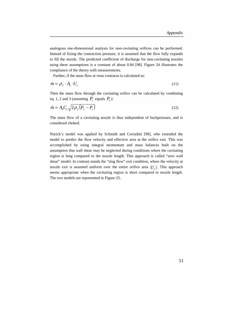
Appendix
51
analogous one-dimensional analysis for non-cavitating orifices can be performed.
Instead of fixing the contraction pressure, it is assumed that the flow fully expands
to fill the nozzle. The predicted coefficient of discharge for non-cavitating nozzles
using these assumptions is a constant of about 0.84 [98]. Figure 24 illustrates the
compliance of the theory with measurements.
Further, if the mass flow at vena contracta is calculated as:
ccf UAm ⋅⋅= ρ& (11)
Then the mass flow through the cavitating orifice can be calculated by combining
eq. 1, 2 and 3 (assuming cP equals vP ):
( )vffc PPCAm −= ρ20& (12)
The mass flow of a cavitating nozzle is thus independent of backpressure, and is
considered choked.
Nurick’s model was applied by Schmidt and Corradini [98], who extended the
model to predict the flow velocity and effective area at the orifice exit. This was
accomplished by using integral momentum and mass balances built on the
assumption that wall shear may be neglected during conditions where the cavitating
region is long compared to the nozzle length. This approach is called “zero wall
shear” model. In contrast stands the “slug flow” exit condition, where the velocity at
nozzle exit is assumed uniform over the entire orifice area ( )aU . This approach
seems appropriate when the cavitating region is short compared to nozzle length.
The two models are represented in Figure 25.

Experimental Investigation of Impinging Diesel Sprays for HCCI Combustion
52
Figure 25. (a) Sketch of the physical process represented by the slug flow exit condition. Wall shear is assumed to be responsible for the change in velocity profile from point C to point a. (b) Sketch of the physical process represented by the zero wall shear model. The flow downstream of the cavities has low velocity and does not transfer momentum to the walls. All losses are the result of the uncontrolled expansion of the liquid into vapour (from [98]).
The models bound the range of exit momentum; the slug flow exit condition has the
least possible momentum flux, and the zero wall shear assumption gives the greatest
possible momentum. The exit conditions of the zero wall shear model is represented
as a slug flow with an effective cross-sectional area Af and a velocity of Uf.
Conservation of mass and momentum gives:
)(2
)21(2
vffc
vcafcf
PPC
PCPPCU
−−+−
=ρ
(13)
where this velocity occupies an effective area, Af, given by:
0
2
)21(2
)(2A
PCPPC
PPCA
vcafc
vfcf −+−
−= (14)
Since mass flow is a fixed parameter, 0/ AAf equals fa UU / . K is plotted as a
function of CD, Bernf UU / and 0/ AAf in Figure 26. It appears that at high
injection pressures (compared to downstream pressure) the vena contracta measured

Appendix
53
by CC dominates the behaviour of the nozzle. In the limit as K approaches unity,
both CD and 0/ AAf approach CC. This means that for high injection pressures the
CD represents the fraction of area occupied by the liquid jet. However, for values of
K larger than approximately 1.8, the slug flow model appears superior.
To be able to use the previous analysis, the value of CC must be known. The value
can of course be calculated using eq. 6, however in reality the value is very sensitive
to nozzle geometry. Instead, CD can be measured experimentally; the CC can be
calculated using eq. 10. Once CC is known, the exit momentum, effective area and
effective velocity can be calculated.
1 1,1 1,2 1,3 1,4 1,5 1,6 1,7 1,8 1,9 20,5
0,6
0,7
0,8
0,9
1
K
CD
Af/A
0
Uf/U
Bern
Figure 26. Predicted orifice coefficients of the exiting flow. The coefficient of contraction for these calculations is assumed to be 0.611.
The nozzle velocity- and area coefficients are Bernfv UUC /= and
0/ AAC fa = , where avD CCC ⋅= .
The above technique allows for the calculation of the orifice coefficients using the
measured CD in combination with the zero wall shear model. The zero wall shear
model gains credibility from measurements of exit velocities in diesel nozzles. For
example Chaves et al. [69] measured CD of 0.7, however exit velocities were close
to ideal Bernoulli estimate. Winklhofer et al. [66] measured exit velocities between
90 – 95 % of Bernoulli estimate using LIF. The nozzle geometries were however
rectangular with glasses on two sides to allow for optical access, which may increase
the wall shear compared to the diesel nozzle geometry.
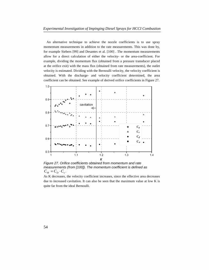
Experimental Investigation of Impinging Diesel Sprays for HCCI Combustion
54
An alternative technique to achieve the nozzle coefficients is to use spray
momentum measurements in addition to the rate measurements. This was done by,
for example Siebers [99] and Desantes et al. [100] . The momentum measurements
allow for a direct calculation of either the velocity- or the area-coefficient. For
example, dividing the momentum flux (obtained from a pressure transducer placed
at the orifice exit) with the mass flux (obtained from rate measurements), the outlet
velocity is estimated. Dividing with the Bernoulli velocity, the velocity coefficient is
obtained. With the discharge- and velocity coefficient determined, the area
coefficient can be obtained. See example of derived orifice coefficients in Figure 27.
Figure 27. Orifice coefficients obtained from momentum and rate measurements (from [100]). The momentum coefficient is defined as
vDM CCC ⋅= .
As K decreases, the velocity coefficient increases, since the effective area decreases
due to increased cavitation. It can also be seen that the maximum value at low K is
quite far from the ideal Bernoulli.

Appendix
55
Derivation of the spray model Naber and Siebers [61] have derived a spray model based on conservation of mass
and momentum using integral control surface techniques. The development has two
steps: (1) derivation of a relationship for the spay tip velocity, and (2) integration of
the velocity relationship to obtain a correlation for tip penetration time versus
penetration distance. A schematic of the model is shown in Figure 28.
Entrained Gas: Pa, a
U(x)A(x)
Uf
Af
X
α / 2
Pf
ρf
FUEL
Control Surface
X'
Figure 28. Schematic of the spray model for the penetration correlation.
Major assumptions made in the analysis are that the spray has:
1. Uniform velocity profile.
2. Constant injection velocity with instantaneous start.
3. No velocity slip between fuel and entrained air.
4. Quasisteady flow with uniform growth rate. (i.e. constant angle α).
The first assumption is a gross simplification of reality. The second assumption
excludes conditions where the injection rate “ramps up” over a significant period of
time, or does not remain constant during the injection. This is generally no problem
with common rail systems, which usually has a “square” rate profile. The third
assumption is doubtful near the nozzle tip, but is assumed to hold for larger
distances. However, air entrainment measurements suggest an existing slip also in
the spray tip, see section on air entrainment. The fourth assumption is supported

Experimental Investigation of Impinging Diesel Sprays for HCCI Combustion
56
since the sprays are found to have virtually axially uniform spray angles, except at
the initial transient period. ([61], [101]).
Using the control surface, fuel mass and momentum balances can be written:
( ) ( ) ( )xUxAUA fffff ⋅⋅=⋅⋅ ρρ 0 (15)
( ) ( ) ( ) ( ) ( )2220 xUxAxUxAUA aafffff ⋅⋅+⋅⋅=⋅⋅ ρρρ (16)
where fρ and aρ are densities of injected fuel and entrained ambient air. fU and
( )0fA are axial velocity and cross-sectional area of the fuel at the exit of the
orifice. ( )xU , ( )xAf and ( )xAa are the spray velocity and the cross sectional
areas of the fuel and air at any location x in the spray.
Additionally, a third equation is added, defined as:
( ) ( ) ( )xAmxAxA fa ⋅−= (17)
where the area ( )xA is the total cross-sectional area of the jet at x , m is a
parameter with value 1 or 0. Setting m to zero, as is done later, is the equivalent to
neglecting the cross-sectional area of the spray occupied by the fuel.
Solving eq. 15 – 17 with respect to ( )xU results in:
( ) ( )( )
( )( )
⎟⎟⎟⎟⎟
⎠
⎞
⎜⎜⎜⎜⎜
⎝
⎛
−
⎟⎟⎠
⎞⎜⎜⎝
⎛−
⋅⋅+⋅⎟⎟
⎠
⎞⎜⎜⎝
⎛−⋅⋅= 1
041
0
2 2
m
A
xA
mxA
AUxU
a
f
a
f
f
a
fff
ρρ
ρρ
ρρ
(18)
The spray velocity in Eq. 18 applies at all x in the “model” spray. If the following
substitutions and non-dimensionalizations are made:
a
f
ρρ
ρ =~ (19)
( )2/tan20 αfdm
x ⋅= (20)
0' xxx += (21)
)('
'xU
dt
dx
dt
dx == (22)

Appendix
57
[ ]2)2/tan(')( απ ⋅⋅= xxA (23)
2
4)0( ff dA ⋅= π
(24)
( )2/tan1
~~
~ 2
1
αρρρ
⋅⋅⎟⎟⎠
⎞⎜⎜⎝
⎛ −⋅⋅=+
a
mdx f (25)
( )2/tan1
~
~~
2
2
1
αρρρ
⋅⋅⋅⎟⎟
⎠
⎞⎜⎜⎝
⎛ −⋅=+
aU
mdt
ff (26)
+= xxx /'~ (27)
+= ttt /'~ (28)
then, after some algebraic manipulation, eq. 18 simplifies to:
1~161
2~~
2 ++=
xtd
xd (29)
In the above equations, the distance 0x is the location of the orifice exit relative to
the projected origin of the spray. The diameter fd is the diameter of the fuel stream
exiting the orifice. The angle ( )2/α is defined in Figure 28. The terms 't and 'x
are the coordinates referenced to the projected origin. +t and +x are scaling
parameters. a is an arbitrary constant.
The final step in the derivation is to assume that ( )xU is equal to the spray tip
velocity and integrate eq. 29 from 0~ =x to Sx~~ = , where += xSS /'
~ and 'S is
the spray tip location relative to projected origin. The integration yields the
dimensionless penetration time, t~ , as a function of the dimensionless penetration
distance, S~
, both referenced to the projected spray origin in Figure 28.
( )22 ~161
~4ln
161~
1614
~
2
~~ SSS
SSt ⋅++⋅⋅+⋅+⋅+= (30)
Integrating eq. 30 in the limit of t~ approaching zero (i.e. x~ approaching zero):
tS
t
Limit ~~
0~=
→ (31)
Experimental Investigation of Impinging Diesel Sprays for HCCI Combustion
58
The long time limit is derived by integrating eq. 30 in the limit of t~ approaching
infinity (i.e. x~ approaching infinity):
2
1~~
~tS
t
Limit =∞→
(32)
The transition of a linear to square root dependence of penetration with time occurs
in the vicinity of 1~ =t . In the transition region, the spray evolves from one
dominated by the injected fluid to one dominated by entrained air.
Given the small value of 0x , (which is typically 0.5 mm) and the unphysical fact
that air entrainment would occur inside the nozzle, when the projected spray origin
is inside the nozzle, the fuel flow area in eq. 15 is neglected. This is done by setting
0=m in eq. 17 – 30. The result is that the projected spray origin in Figure 28 shifts
to the orifice exit plane and the injected fuel is treated as a point source of
momentum.
The velocity fU and effective orifice diameter fd in the previous equations is
determined using the following relationships:
fafvf PPCU ρ/)(2 −⋅= (33)
dCd af ⋅= (34)
Equation 33 is the Bernoulli relationship for orifice exit flow, where fP is the fluid
pressure, aP is the ambient gas pressure, vC and aC are the velocity and area
coefficients discussed in the previous section.
The relationship between the model spray angle α and the “measured” spray
angle θ obtained from spray images is defined as:
)tan()tan( θα ⋅= a (35)
A value of 0.66 of the arbitrary constant a , was found to provide the best
agreement between data and model in the investigation by Naber and Siebers [61]. A
later investigation by Siebers et al. [102] resulted in a value of 0.75, due to a
difference in how aC was measured. In the study by Wåhlin and Cronhjort [103], a
value of 0.71 gave best agreement. There are several other possible reasons for a
deviation in this value: The pressure drop from the rail (where the injection pressure
is measured) to the sac is not known, differences in how the cone angle and
penetrations are estimated from spray pictures and how the pictures are thresholded.

Abbreviations
59
ABBREVIATIONS
CAD Crank angle degree
CFD Computational fluid dynamics
CO Carbon oxide
DI Direct injection
DPF Diesel particulate filter
EGR Exhaust gas recirculated
EOI End of injection
GDI Gasoline direct injection
H2SO4 Sulphuric acid
HC Hydrocarbon
HCCI Homogeneous charge compression ignition
IMEP Indicated mean effective pressure
LNT Lean NOX trap
MTBE Methyl tertiary butyl ether
N2 Nitrogen
NMHC Non-methane hydro-carbon
NO Nitrogen oxide
NOX Oxides of nitrogen
PAH Polycyclic aromatic hydrocarbons
PCCI Premixed-charge compression-ignition
PI Port injection
PIV Particle imaging velocimetry
PM particulate matter
SCR Selective catalytic reduction
SI Spark-ignited
SMD Sauter mean diameter
SO2 Sulphur dioxide
SOC Start of combustion
SOX Oxides of sulfur

Experimental Investigation of Impinging Diesel Sprays for HCCI Combustion
60
TDC Top dead center
VCO Valve covered orifice
VOC Volatile organic compounds
VVT Variable valve timing

Nomenclature
61
NOMENCLATURE
cA Area at vena contracta
aA Area of air in spay cross-section
fA Effective area of liquid
0A Nozzle hole geometrical area
aC Orifice area contraction coefficient
DC Orifice discharge coefficient
vC Orifice velocity coefficient
MC Momentum coefficient
cC Contraction coefficient
0CC Contraction constant
d Nozzle hole diameter
fd Effective orifice diameter
dl / Nozzle hole length-to-diameter ratio
m Parameter with value 1 or 0
m& Mass flow
fP Injection pressure
aP Ambient pressure
vP
Vapor pressure
cP
Static pressure at vena contracta
t~ Dimensionless time
+t Time scalar
t Time
aU Average velocity at orifice exit
fU Fuel axial exit velocity
BernU Ideal Velocity given by Bernoulli equation
U Spray velocity

Experimental Investigation of Impinging Diesel Sprays for HCCI Combustion
62
cU Velocity at vena contracta
x~ Dimensionless penetration
+x Penetration scalar
x Spray penetration
CN Cavitation number
K Cavitation parameter
a Constant
α Model spray angle
θ Spray cone angle
φ Nozzle impingement angle
aρ Ambient density
fρ Fuel density

References
63
REFERENCES
[1] U.S. Energy Information Administration, 2004, www.eia.doe.gov
[2] United Nations, 2004, www.un.org
[3] International Energy Agency, 2004, www.iea.org
[4] The Intergovernmental Panel on Climate Change (IPCC), 2004, www.ipcc.ch
[5] Bergman H. “Dilution and Measurement of Engine Exhaust Particles” Licentiate Thesis, KTH, Stockholm, Sweden 2004.
[6] Glassman I. “Combustion” third edition, Academic press, 1996.
[7] U.S. environmental protection agency, 2004, www.epa.gov
[8] ”Environmental Effects and Protection (Miljöeffekter, kompendium i miljöskydd, del 4)” Industriellt miljöskydd, KTH 1997.
[9] DieselNet, 2004, www.dieselnet.com
[10] Leet, J.A., Simescu, S., Froelund, K., Dodge, L.G. and Roberts, C.E. ”Emissions solutions for 2007 and 2010 heavy-duty diesel engines” SAE Paper No. 2004-01-0124.
[11] Heywood, J.B. “Internal combustion engine fundamentals”, McGraw-Hill, 1988.
[12] Robert Bosch GmbH “Automotive Handbook” 6th edition, 2004.
[13] Winklhofer, E. “HCCI combustion”, keynote lecture, 6:th international conference on engines in automobiles, 2003.
[14] Dec, J.E. “A Conceptual Model of DI Diesel Combustion Based on Laser-Sheet Imaging”, SAE Paper No. 970873.
[15] Johansson, B. “Homogeneous Charge Compression Ignition – HCCI” Presentation at SAE HCCI symposium, San Francisco, 2004.
[16] Richter, M., Engström, J., Franke, A., Aldén, M., Hultqvist, A. and Johansson, B. “The Influence of Charge Inhomogeneity on the HCCI Combustion Process”, SAE paper No. 2000-01-2868.
[17] Hultqvist, A., Christensen, M., Johansson, B., Franke, A., Richter, M. and Aldén, M. “A Study of the Homogeneous Charge Compression Ignition Combustion Process by Chemiluminescence Imaging”, SAE paper No. 1999-01-3680.
[18] Hultqvist, A., Christensen, M. Johansson, B. “The heterogeneous combustion process in an HCCI engine – optical characterization of fluctuations and length scales”, Proceedings of the IFP International Congress: A New Generation of Engine Combustions for the Future?, Paris, 2001.

Experimental Investigation of Impinging Diesel Sprays for HCCI Combustion
64
[19] Onishi S. et al. “Active Thermo-Atmosphere Combustion (ATAC) – A new combustion process for internal combustion engines”, SAE paper No. 790501.
[20] Hultqvist A. “Characterization of the homogeneous charge compression ignition process”, Doctoral thesis, Lund, 2002.
[21] Kimura S. et al. "New combustion concept for ultra-clean and high-efficiency small DI diesel engines", SAE Paper No. 1999-01-3681.
[22] Ishibashi Y. and Asai M. "Improving the Exhaust Emissions of Two-Stroke Engines by Applying the Activated Radical Combustion", SAE Paper no. 960742.
[23] Hasegawa, R. and Yanagihara, H. “HCCI Combustion in DI Diesel Engine”, SAE Paper No. 2003-01-0745.
[24] Sjöberg, M., Edling, L-O., Eliassen, T., Magnusson, L. and Ångström, H-E. “GDI HCCI: Effects injection timing and air swirl on fuel stratification, combustion and emissions formation”, SAE Paper No. 2002-01-0106.
[25] Marriott C. D. and Reitz R. D. “Experimental Investigation of Direct Injection-Gasoline for Premixed Compression Ignited Combustion Phasing Control”, SAE Paper No. 2002-01-0418.
[26] Marriott, C.D., Kong, S-C. and Reitz R. D. “Investigation of Hydrocarbon Emissions from a Direct-Injection Gasoline Premixed Charge Compression Ignited Engine”, SAE Paper No. 2002-01-0419.
[27] Dec, J. E. and Sjöberg, M., “A Parametric Study of HCCI Combustion – the Sources of Emission at Low Loads and the Effects of GDI Fuel Injection”, SAE Paper 2003-01-0752.
[28] Sun, Y., Shuai, S-J., Wang, J-X. and Wang, Y-J. “Numerical Simulation of Mixture Formation and Combustion of Gasoline Engines with Multi-Stage Direct Injection Compression Ignition (DICI)”, SAE Paper No. 2003-01-1091.
[29] Dec, J. E. and Sjöberg, M., “Isolating the Effects of Fuel Chemistry on Combustion Phasing in an HCCI Engine and the Potential of Fuel Stratification for Ignition Control”, SAE Paper 2004-01-0557.
[30] Gray A. W. and Ryan T. W. “Homogeneous charge compression ignition (HCCI) of diesel fuel”, SAE Paper No. 971676.
[31] Suzuki H., Koike, N. and Ishii, H. and Odaka, M. “Exhaust Purification of Diesel Engines by Homogeneous Charge with Compression Ignition part 1: Experimental Investigation of Combustion and Exhaust Emission Behavior under Pre-Mixed Homogeneous Charge Compression Ignition Method”, SAE Paper No. 970313.

References
65
[32] Christensen, M., Hultqvist, A. and Johansson, B. “Demonstrating the multi fuel capability of a homogeneous charge compression ignition engine with variable compression ratio”, SAE paper No. 1999-01-3679.
[33] Nandha K.P. and Abraham J., “Dependence of fuel-air mixing characteristics on injection timing in an early-injection diesel engine”, SAE Paper No. 2002-01-0944.
[34] Stanglmaier, R.H., Ryan, T.W. and Mehta, D. “Fuel Introduction Strategies for Premixed Compression Ignition Combustion”, Proceedings of the IFP International Congress: A New Generation of Engine Combustions for the Future?, Paris, 2001.
[35] Musculus, M.P.B. “Multiple Simultaneous Optical Diagnostic Imaging of Early-Injection Low-Temperature Combustion in a Heavy-Duty Diesel Engine”, SAE Paper No. 2006-01-0079.
[36] Groenendijk, A. and Müller, E. “Mixture Formation and Combustion Control for Low Emission DI Diesel Combustion with HCCI-Characteristics”, THIESEL, 2002.
[37] Takeda, Y., Keiichi, N. and Keiichi, N. “Emission characteristics of premixed lean diesel combustion with extremely early staged fuel injection”, SAE Paper No. 961163.
[38] Hashizume, T., Akagawa, H. and Tsujimura, K. “Combustion and emission characteristics of multiple stage diesel combustion”, SAE Paper No. 980505.
[39] Akagawa, H., Miyamoto, T., Harada, A., Sasaki, S., Shimazaki, N., Hashizume, T. and Tsujimura, K. “Approaches to solve problems of the premixed lean diesel combustion”, SAE Paper No. 1999-01-0183.
[40] Nishijima, Y., Asaumi, Y. and Aoyagi, Y. “Premixed Lean Diesel Combustion (PREDIC) using Impingement Spray System”, SAE Paper No. 2001-01-1892.
[41] Iwabuchi, Y., Kawai, K., Shoji, T. and Takeda, Y. “Trial of New Concept Diesel Combustion System – Premixed Compression-Ignited Combustion” SAE Paper No. 1999-01-0185.
[42] Nordgren, H., Hultqvist, A. and Johansson B. “Start of Injection Strategies for HCCI combustion”, SAE Paper No. 2004-01-2990.
[43] Harada, A., Shimazaki, N., Sasaki, S., Miyamoto, T., Akagawa, H. and Tsujimura, K. “The effects of mixture formation on premixed lean diesel combustion”, SAE Paper No. 980533.
[44] Ishima, T., Matsuda, T., Shiga, S., Araki, M., Nakamura, H., Obakata, T., Yang, X., Long, W-Q. and Murakami, A. “Characteristics of HCCI
Experimental Investigation of Impinging Diesel Sprays for HCCI Combustion
66
Diesel Combustion Operated with a Hollow Cone Spray”, SAE Paper No. 2003-01-1823.
[45] Ra, Y., Hruby, E. J. and Reitz, R. D. “Parametric study of combustion characteristics in a direct-injection diesel homogeneous charge compression ignition engine with a low-pressure fuel injector”, IMechE, vol. 6, pp 215 – 230, 2005.
[46] Gatellier, B., Walter, B. and Miche, M. “New Diesel Combustion Process to Achieve Near Zero NOX and Particulates Emissions”, Proceedings of the IFP International Congress: A New Generation of Engine Combustions for the Future?, Paris, 2001.
[47] Shimazaki, N., Tsurushima, T. and Nishimura T. “Dual Mode Combustion Concept with Premixed Diesel Combustion by Direct Injection Near Top Dead Center”, SAE Paper No. 2003-01-0742.
[48] Helmantel, A. and Denbratt, I. “HCCI Operation of a Passenger Car Common Rail DI Diesel Engine With Early Injection of Conventional Diesel Fuel”, SAE Paper No. 2004-01-0935.
[49] Helmantel, A., Gustavsson, J. and Denbratt, I. “Operation of a DI Diesel Engine With Variable Effective Compression Ratio in HCCI and Conventional Diesel Mode”, SAE Paper No. 2005-01-0177.
[50] Buchwald, R., Brauer, M., Blechstein, A., Sommer, A. and Kahrstedt, J. “Adaption of Injection System Parameters to Homogeneous Diesel Combustion”, SAE Paper No. 2004-01-0936.
[51] Kanda, T., Hakozaki, T., Uchimoto, T., Hatano, J., Kitayama, N. and Sono, H. “PCCI Operation with Early Injection of Conventional Diesel Fuel”, SAE Paper No. 2005-01-3837.
[52] Hardy, W.L. and Reitz, R.D. “A study on the Effects of High EGR, High Equivalence Ratio, and Mixing Time on Emissions Levels in a Heavy-Duty Diesel Engine for PCCI Combustion”, SAE Paper No. 2006-01-0026.
[53] Lee, S. and Reitz, R.D. “Spray Targeting to Minimize Soot and CO Formation in Premixed Charge Compression Ignition (PCCI) Combustion with a HSDI Diesel Engine”, SAE Paper No. 2006-01-0918.
[54] Kimura, S., Aoki, O., Ogawa, H., Muranaka, S. and Enomoto, Y. “New Combustion Concept for Ultra-Clean and High-Efficiency Small DI Diesel Engines”, SAE Paper No. 1999-01-3681.
[55] Ogawa, H., Kimura, S., Koike, M. and Enomoto, Y. “A Study of Heat Rejection and Combustion Characteristics of a Low- Temperature and Pre-Mixed Combustion Concept Based on Measurement of

References
67
Instantaneous Heat Flux in a Direct-Injection Diesel Engine”, SAE Paper No. 2000-01-2792.
[56] Kimura, S., Aoki, O., Kitahara, Y and Aiyoshizawa, E. “Ultra-Clean Combustion Technology Combining a Low-Temperature and Premixed Combustion Concept for Meeting Future Emission Standards”, SAE Paper No. 2001-01-0200.
[57] Miles, P.C., Choi, D., Pickett, L.M., Singh, I.P., Henein, N., RempelEwert, B.A., Yun, H. and Reitz, R.D.” Rate-Limiting Processes in Late-Injection, Low-Temperature Diesel Combustion Regimes”, THIESEL, 2004.
[58] Lefebvre, A. H. “Atomization and Sprays”, Taylor & Francis, ISBN 0-891116-603-3, 1989.
[59] G.J. Smallwood and Ö.L. Gülder “Views on the Structure of transient diesel sprays”, Atomization and Sprays, vol. 10, pp. 355-386, 2000.
[60] Hiroyasu, H. and Arai, M. “Structures of Fuel Sprays in Diesel Engines”, SAE Paper No. 900475.
[61] Naber, J. D. and Siebers, D. L. “Effects of Gas Density and Vaporization on Penetration and Dispersion of Diesel Sprays”, SAE Paper No. 960034.
[62] Soteriou, C., Andrews, R. and Smith, M. “Further Studies of Cavitation and Atomization in Diesel Injection”, SAE Paper No. 1999-01-1486.
[63] Kim, J. H., Nishida, K. And Hiroyasu, H. “Characteristics of the Internal Flow in a Diesel Injection Nozzle”, Proceedings of ICLASS-97, Seoul.
[64] H. Hiroyasu “spray breakup mechanism from the hole-type nozzle and its applications”, Atomization and Sprays, vol. 10, pp. 511-527, 2000.
[65] Bergwerk, W. “Flow Pattern in Diesel Nozzle Spray Holes”, Proc. Inst. Mech. Eng., Vol.173, pp.655-660, 1959.
[66] Winklhofer, E., Kelz, E. and Morozov, A. “Basic flow processes in high pressure fuel injection equipment”, ICLASS, 2003.
[67] Soteriou, C., Andrews, R. and Smith, M. “Direct Injection Diesel Sprays and the Effect of Cavitation and Hydraulic Flip on Atomization”, SAE Paper No. 950080.
[68] Schmidt, D. P., Rutland, C.J., Corradini, M.L., Roosen, P. and Genge, O. “Cavitation in Two-Dimensional Asymmetric Nozzles”, SAE Paper No. 1999-01-0518.
[69] Chaves, H., Knapp, M. and Kubitzek, A. “Experimental study of Cavitation in the Nozzle Hole of Diesel Injectors Using Transparent Nozzles”, SAE Paper No. 950290.

Experimental Investigation of Impinging Diesel Sprays for HCCI Combustion
68
[70] Colicott, S.H. and Haiyun, L. “True-scale True-pressure Internal Flow Visualization for Diesel Injectors”, SAE Paper No. 2006-01-0890.
[71] Siebers, D. L. “Liquid-Phase Fuel Penetration in Diesel Sprays”, SAE Paper No. 980809.
[72] Sasaki, S., Akagawa, H., Tsujimura, K., “A Study on Surrounding Air Flow Induced by Diesel Sprays”, SAE Paper No. 980805.
[73] Ishikawa, N. and Zhang, L. “Characteristics of Air-Entrainment in a Diesel Spray”, SAE Paper No. 1999-01-0522.
[74] Rajalingam, B. V. and Farrell P. V. “The Effect of Injection Pressure on Air Entrainment Into Transient Diesel Sprays”, SAE Paper No. 1999-01-0523.
[75] Rhim, D.R. and Farrell P. V. “Characteristics of Air Flow Surrounding Non-Evaporating Transient Diesel Sprays”, SAE Paper No. 2000-01-2789
[76] Rhim, D.R. and Farrell P. V. “Effect of Gas Density and the Number of Injector Holes on the Air Flow Surrounding Non-Evaporating Transient Diesel Sprays”, SAE Paper No. 2001-01-0532
[77] Rhim, D.R. and Farrell P. V. “Air Flow Characteristics Surrounding Evaporating Transient Diesel Sprays”, SAE Paper No. 2001-01-0499
[78] Rhim, D.R. and Farrell P. V. “Air Flow Surrounding Burning Transient Diesel Sprays”, SAE Paper No. 2002-01-2668
[79] Heidmann, M.F., Priem, R.J. and Humphrey, J.C. ”A study of sprays formed by two impinging jets“, NACA TN 3835, March 1957
[80] Dombrowski, N. and Hooper, P.C. “A study of the sprays formed by impinging jets in laminar and turbulent flow”, Journal of fluid mechanics, Vol. 18 Pt.3, 1963, pp. 392-400
[81] Zung L.B. and White J.R. “combustion process of impinging hypergolic propellants” 7th JANNAF combustion meeting, Chemical propulsion information Agency, Publ. 204, Vol. 1, 1971, pp. 455-474
[82] Fukui N. and Sato M. “The study of a liquid atomization by the impingement of two jets”, bulletin for the Japan society for mechanical engineers, Vol. 15, 1972, p.609
[83] Anderson, W.E., Ryan, H.M., Pal, S. and Santoro, R.J. ”Fundamental studies of impinging liquid jets” AIAA Paper 92-0458, 1992
[84] Ryan, H.M., Anderson, W.E., Pal, S. and Santoro, R.J. ”Atomization characteristics of impinging liquid jets”, Journal of propulsion and power, Vol. 11, No. 1, 1995, pp. 135-145

References
69
[85] Arai, M. and Saito, M. “Atomization characteristics of jet-to-jet and spray-to-spray impingement systems”, Atomization and sprays, Vol. 9. No. 4, 1999, pp. 399-417
[86] Ashgriz, N., Brocklehurst, W. and Talley, D. “Mixing mechanism in a pair of impinging jets”, Journal of propulsion and power, Vol. 17, No. 3, May-June 2001
[87] Tucker, C.L. and Suh, N.P. “Mixing for reaction injection molding. I. Impingement mixing of liquids” Polymer engineering and science, Vol. 20, 1980, p. 875
[88] Mahajan, A.J. and Kirwan, D.J. “Micromixing effects in two impinging jets precipitator” AIChE Journal, Vol. 42, No. 7, 1996
[89] Yamamoto H. and Niimura K. “Characteristics of fuel sprays from specially shaped and impinging flow nozzles” SAE paper No. 950082
[90] Iwabuchi Y., Kawai, K., Shoji, T. and Takeda, Y. “Trial of new concept diesel combustion system – premixed compression-ignited combustion” SAE Paper No. 1999-01-0185
[91] Chiba, T., Saito, M., Amagai, K. and Arai, M. “Characteristics of Interimpingement Diesel Spray”, Atomization and Sprays, vol. 12, pp. 431-449, 2002
[92] Nordgren, H., Hultqvist, A. and Johansson, B. “Start of injection strategies for HCCI combustion”, SAE Paper No 2004-01-2990
[93] Wåhlin F. and Cronhjort A. “Fuel sprays for premixed compression ignited combustion – characteristics of impinging sprays”, SAE paper No. 2004-01-1776
[94] Wåhlin F., Cronhjort, A., Ångström, H-E. and Olofsson, U. “Effect of Injection Pressure and Engine Speed on Air/Fuel Mixing and Emissions in a Pre-Mixed Compression Ignited (PCI) Engine using Diesel Fuel”, SAE Paper No 2004-01-2989
[95] Wåhlin F. “Engine Combustion with Impinging Diesel Sprays”, to be submitted.
[96] Nurick, W.H. “Orifice Cavitation and Its Effects on Spray Mixing”, J. Fluids Eng., Vol.98, pp.681-687, 1976.
[97] Sarre, C.vK., Kong, S-C and Reitz, R.D. “Modeling the Effects of Injector Nozzle Geometry on Diesel Sprays”, SAE Paper No. 1999-01-0912.
[98] Schmidt, David P. and Corradini, M. L. “Analytical Prediction of the Exit Flow of Cavitating Orifices”, Atomization and Sprays, vol. 7, pp. 603-616, 1997
Experimental Investigation of Impinging Diesel Sprays for HCCI Combustion
70
[99] Siebers, D. L. “Scaling Liquid-Phase Fuel Penetration in Diesel Sprays Based on Mixing-Limited Vaporization”, SAE Paper No. 1999-01-0528.
[100] Desantes, J.M., Payri, R., Salvador, F.J. and Gimeno J. ”Measurements of Spray Momentum for the Study of Cavitation in Diesel Injection Nozzles”, SAE Paper No. 2003-01-0703.
[101] Araneo, L. and Coghe, A. “Effect of injection conditions on penetration and drop size of HCCI diesel sprays”, Thiesel 2002.
[102] Siebers, D., Higgins, B. and Pickett, L. “Flame Lift-Off on Direct-injection Diesel Fuel Jets: Oxygen Concentration Effects”, SAE Paper No. 2002-01-0890.
[103] Wåhlin, F. and Cronhjort, A. “Impinging Diesel Sprays”, Atomization and Sprays, to be published, 2007.


![HCCI - Update of Progress 2005 - US Department of Energy · HCCI – Update of Progress 2005 HCCI HCCI ... M EP [b a r] B S F C [g/k W-hr] ... Typically used in 2-Stroke Engines at](https://static.fdocuments.us/doc/165x107/5ac4ebc77f8b9a220b8d1053/hcci-update-of-progress-2005-us-department-of-energy-update-of-progress.jpg)