Experimental Investigation of Different Groove Geometry of ... · some of the incipient features of...
4
International Journal of Science and Research (IJSR) ISSN (Online): 2319-7064 Index Copernicus Value (2013): 6.14 | Impact Factor (2013): 4.438 Volume 4 Issue 6, June 2015 www.ijsr.net Licensed Under Creative Commons Attribution CC BY Experimental Investigation of Different Groove Geometry of Hydrodynamic Journal Bearing On Mechanical Vibrations Rohit Prataprao Patil 1 , Prof. M. B. Mandale 2 1 Department of Mechanical Engineering, Rajarambapu Institute of Technology, Sakharale 415414, India 2 Department of mechanical engineering, Rajarambapu Institute of Technology, Sakharale 415414, India Abstract: Hydrodynamic journal bearings are commonly used components in machinery for a wide range of applications. This work represents investigation of performance of hydrodynamic journal bearings with different groove geometry. In this work bearing with two helical, three helical groove and non groove (plain) are tested at radial load and RPM are varied within specified range and experimental vibration signals were obtained. Vibration signals analysis has been carried out in Frequency domain by FFT analyzer. Results of experimentation were in amplitude versus speed. Keywords: helical groove, Frequency domain, FFT analyzer 1. Introduction Vibration is an effective tool in detecting and diagnosing some of the incipient features of machines and equipments. A vibration signature measured on external surface of a machine or structure contains a good amount of information, which, if properly interpreted can reveal the running condition of machine. A vibration signature taken from appropriate location in a machine can reveal presence of machine defects such as imbalance, misalignment, imperfect foundations, mechanical looseness, rubs, bearing defects, faults in transmission drives etc. There is trend of monitoring different machine components with the help of data generated by vibration by these components for ensuring their reliable and effective working. Bearing vibration analysis is becoming popular for monitoring bearing performance. Bearings play a vital role in rotating machinery. They support radial loads, axial loads, thrust loads etc. and provide frictionless running of rotors. Journal bearings are widely used in different rotating machines. These bearings allow for transmission of large loads at mean speed of rotation. On the basis of way to provide the carrying capacity, we recognize radial hydrodynamic bearings and hydrostatic bearings. In hydrodynamic bearings lubricant is fed through a throttling hole and carrying capacity is produced as a result of hydro- dynamic pressure in the wedge shaped clearance between plain bearing and the shaft. Hydrodynamic journal bearing is a critical component in various machines like rotors, turbines, pumps, hard disk etc. It comes under the group of machine elements working under elasto-hydrodynamic lubrication (EHL) conditions. Due to radial clearance journal bearings have self induced vibrations. Lots of efforts are made by researchers to study such vibrations and effects of vibrations on bearing performance and methods to reduce these vibrations. The journal bearing surfaces encountered in many studies were assumed to be smooth. However, the possibility of improving bearing performance by modifying bearing surface geometry has attracted attention of many researchers and they have performed several theoretical studies on hydrodynamic lubrication field for rough journal bearing surfaces in recent years. 2. Design of Experimental Setup For the desired experimental analysis design the experimental setup as shown in fig. 1. For this setup we have used the speed control motor of motor of variable speed control. The coupling used L095 and shaft material for shaft EN24. The hydrodynamic bearing is made of brass. Shaft is designed on the basis of Strength Basis, torsional rigidity basis, Shaft design for fatigue life. The bearing is designed by using Raimondi and Boyd chart. Figure 1: Proposed experimental setup 3. Experimental Set Up For testing built the laboratory journal bearings test rig. It is modified specifically for this research to use in effect of different groove geometry on mechanical vibrations of the bearings, shown in Figure 2. The test rig consists of a rigid Paper ID: SUB155330 869
Transcript of Experimental Investigation of Different Groove Geometry of ... · some of the incipient features of...
International Journal of Science and Research (IJSR) ISSN (Online): 2319-7064
Index Copernicus Value (2013): 6.14 | Impact Factor (2013): 4.438
Volume 4 Issue 6, June 2015
www.ijsr.net Licensed Under Creative Commons Attribution CC BY
Experimental Investigation of Different Groove
Geometry of Hydrodynamic Journal Bearing On
Mechanical Vibrations
Rohit Prataprao Patil1, Prof. M. B. Mandale
2
1Department of Mechanical Engineering, Rajarambapu Institute of Technology, Sakharale 415414, India 2Department of mechanical engineering, Rajarambapu Institute of Technology, Sakharale 415414, India
Abstract: Hydrodynamic journal bearings are commonly used components in machinery for a wide range of applications. This work
represents investigation of performance of hydrodynamic journal bearings with different groove geometry. In this work bearing with
two helical, three helical groove and non groove (plain) are tested at radial load and RPM are varied within specified range and
experimental vibration signals were obtained. Vibration signals analysis has been carried out in Frequency domain by FFT analyzer.
Results of experimentation were in amplitude versus speed.
Keywords: helical groove, Frequency domain, FFT analyzer
1. Introduction
Vibration is an effective tool in detecting and diagnosing
some of the incipient features of machines and equipments. A
vibration signature measured on external surface of a machine
or structure contains a good amount of information, which, if
properly interpreted can reveal the running condition of
machine. A vibration signature taken from appropriate
location in a machine can reveal presence of machine defects
such as imbalance, misalignment, imperfect foundations,
mechanical looseness, rubs, bearing defects, faults in
transmission drives etc. There is trend of monitoring different
machine components with the help of data generated by
vibration by these components for ensuring their reliable and
effective working. Bearing vibration analysis is becoming
popular for monitoring bearing performance.
Bearings play a vital role in rotating machinery. They support
radial loads, axial loads, thrust loads etc. and provide
frictionless running of rotors. Journal bearings are widely
used in different rotating machines. These bearings allow for
transmission of large loads at mean speed of rotation. On the
basis of way to provide the carrying capacity, we recognize
radial hydrodynamic bearings and hydrostatic bearings. In
hydrodynamic bearings lubricant is fed through a throttling
hole and carrying capacity is produced as a result of hydro-
dynamic pressure in the wedge shaped clearance between
plain bearing and the shaft.
Hydrodynamic journal bearing is a critical component in
various machines like rotors, turbines, pumps, hard disk etc.
It comes under the group of machine elements working under
elasto-hydrodynamic lubrication (EHL) conditions. Due to
radial clearance journal bearings have self induced vibrations.
Lots of efforts are made by researchers to study such
vibrations and effects of vibrations on bearing performance
and methods to reduce these vibrations. The journal bearing
surfaces encountered in many studies were assumed to be
smooth. However, the possibility of improving bearing
performance by modifying bearing surface geometry has
attracted attention of many researchers and they have
performed several theoretical studies on hydrodynamic
lubrication field for rough journal bearing surfaces in recent
years.
2. Design of Experimental Setup
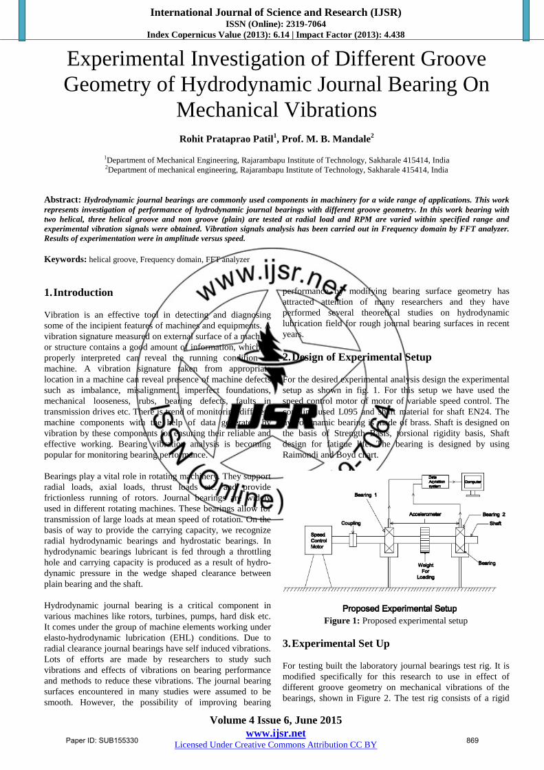
For the desired experimental analysis design the experimental
setup as shown in fig. 1. For this setup we have used the
speed control motor of motor of variable speed control. The
coupling used L095 and shaft material for shaft EN24. The
hydrodynamic bearing is made of brass. Shaft is designed on
the basis of Strength Basis, torsional rigidity basis, Shaft
design for fatigue life. The bearing is designed by using
Raimondi and Boyd chart.
Figure 1: Proposed experimental setup
3. Experimental Set Up
For testing built the laboratory journal bearings test rig. It is
modified specifically for this research to use in effect of
different groove geometry on mechanical vibrations of the
bearings, shown in Figure 2. The test rig consists of a rigid
Paper ID: SUB155330 869
International Journal of Science and Research (IJSR) ISSN (Online): 2319-7064
Index Copernicus Value (2013): 6.14 | Impact Factor (2013): 4.438
Volume 4 Issue 6, June 2015
www.ijsr.net Licensed Under Creative Commons Attribution CC BY
tubular steel base. On this steel frame motor is mounted and
the shaft is coupled to the motor with the help of love joint
coupling. Also on the frame there is special arrangement for
the mountings of the hydrodynamic journal bearings equipped
with oil supply. There was a circular oil groove at the center
of the bearing wall to enable sufficient supply of oil on the
contacting surfaces. The test device operates with a 180 V
single phase electrical DC motor. There is arrangement for
the continuous supply of the oil as shown in the figure. Also
there is oil bath for the outlet oil.
The pedestal jig bearing is used for the loading purpose. To
operate the motor we have used dimmerstat and rectifier unit.
Connect dimmerstat, rectifier and motor in series. With help
of dimmerstst we can vary the speed of the motor.
The experiments were first conducted for the plain journal
bearings for four different loadings. First check the amplitude
of vibration at no load at different speed as 300 rpm, 900 rpm
and 1500 rpm. Then we have done same for 3 kg, 5 kg and 8
kg loading conditions.
In this experiment first take non groove journal bearing.
With the help of FFT analyzer measure the amplitude of
vibrations at different speed and different loading conditions.
When using the FFT analyzer use two accelerometers for the
measurement of the amplitude of vibration. One is mounted
on the bearing which is near to the motor which is called as
drive and other is mounted on the bearing which is away from
the motor i.e. drive end bearing. The accelerometer sensors
are mounted horizontally as well as vertically. First take
reading for the non groove journal bearing by mounting
sensors horizontally at no load and then the readings were
taken for vertically mounted sensors. Repeat the procedure
for 3kg and 8kg loading. After that repeat the procedure for
remaining two helical grooves and three helical groove
journal bearings. Continuous oil supply is given to the
bearings. And at different speed of the shaft we measure the
amplitude of vibration.
Figure 2: Experimental setup
4. Results and Discussions
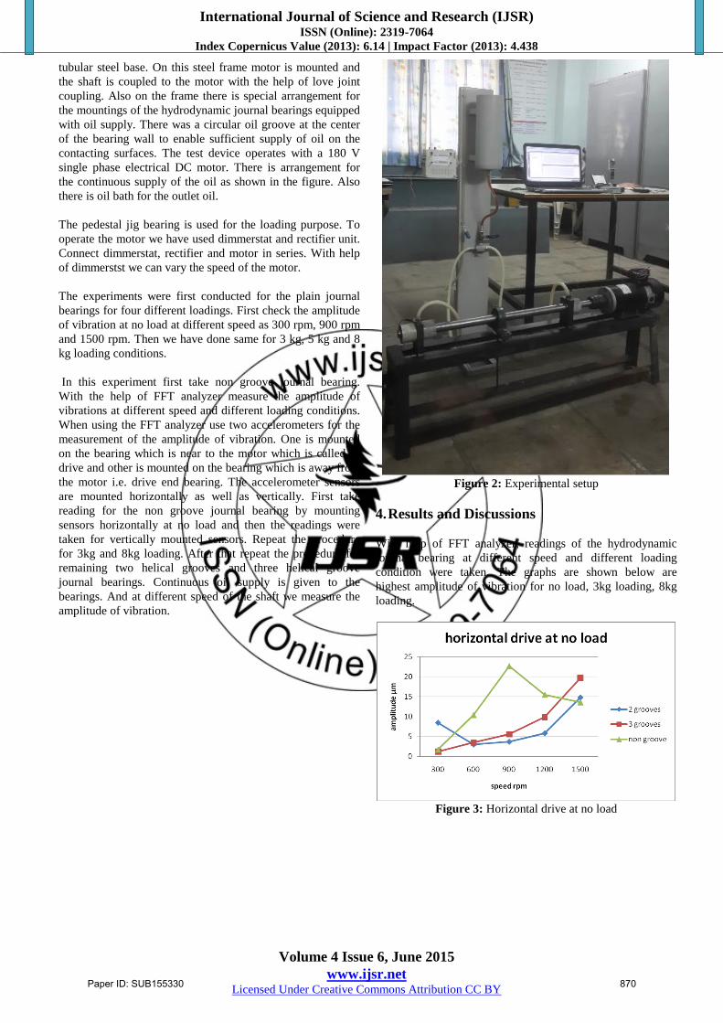
With help of FFT analyzer, readings of the hydrodynamic
journal bearing at different speed and different loading
condition were taken. The graphs are shown below are
highest amplitude of vibration for no load, 3kg loading, 8kg
loading.
Figure 3: Horizontal drive at no load
Paper ID: SUB155330 870

International Journal of Science and Research (IJSR) ISSN (Online): 2319-7064
Index Copernicus Value (2013): 6.14 | Impact Factor (2013): 4.438
Volume 4 Issue 6, June 2015
www.ijsr.net Licensed Under Creative Commons Attribution CC BY
Figure 4: horizontal drive end at no load
Figure 5: vertical drive at no load
Figure 6: vertical drive end at no load
Figure 7: horizontal drive at 3kg load
Figure 8: horizontal drive end at 3kg load
Figure 9: vertical drive at 3kg load
Figure 10: vertical drive end at 3 kg load
Figure 11: horizontal drive at 8kg load
Paper ID: SUB155330 871

International Journal of Science and Research (IJSR) ISSN (Online): 2319-7064
Index Copernicus Value (2013): 6.14 | Impact Factor (2013): 4.438
Volume 4 Issue 6, June 2015
www.ijsr.net Licensed Under Creative Commons Attribution CC BY
Figure 12: horizontal drive end at 8kg load
Figure 13: vertical drive end at 8kg load
Figure 14: vertical drive end at 8kg load
5. Conclusions
At no load condition for lower speed non groove i.e. plain
journal bearing shows higher amplitude of vibration than
other two helical groove and three helical groove journal
bearings.
Speed as well as load increase for non groove journal
bearing it has less amplitude of vibration than other
bearings.
Also for speed above 1500 rpm at no load condition as well
as at loading condition the non groove i.e. plain journal
bearing shows less amplitude of vibration.
At speed up to 1000 rpm two helical groove journal bearing
has less amplitude of vibration than other bearings.
As the load increases and speed up to 1000 rpm the
amplitude of vibration for three helical groove journal
bearing decreases.
Initially both two helical groove and three helical groove
journal bearing shows less amplitude of vibration for no
load, 3kg and 8kg loading but for higher speed i.e. speed
above 900 rpm they shows higher amplitude of vibration
than non groove journal bearing.
References
[1] Hakan Adatepe, Aydın Bıyıklıoglu, Hasan Sofuoglu, “An
investigation of tribological behaviors of dynamically
loaded non-grooved and micro-grooved journal
bearings”, Tribology International, 2013, pp 12-19.
[2] Tandon N, Choudhary A.A., “A review of vibration and
acoustic measurement methods for the detection of
defects in rolling element bearings”, Tribology
International, 1999, 32, pp. 469-480.
[3] Pavle Boskoski, Janko Petrovcic, Bojan Musizza, Dani
Juricic, “Detection of lubrication starved bearings in
electrical motors by means of vibration analysis”,
Tribology International, 2010, 43, pp. 1683-1692.
[4] Zengli Wang, Xiaoling Yu, Feilong Liu, Quanke Feng,
Qin Tan, “Dynamic analyses for the rotor-journal bearing
system of a variable speed rotary compressor”,
International Journal of Refrigeration, 2013, pp 1938-
1950.
[5] J. Sep, P. Pawlus, L. Galda, “The effect of helical groove
geometry on journal abrasive wear”, Archives of Civil
and Mechanical Engineering, 2013, pp 150 -157.
[6] Abhinay V. Dube, L. S. Dhamande, P. G. Kulkarni,
"Vibration Based Condition Assessment Of Rolling
element Bearings With Localized Defect", International
Journal of Scientific & Technology Research, April
2013, volume 2.
[7] Shyam Patidar, Pradeep Kumar Soni, "An Overview on
Vibration Analysis Techniques for the Diagnosis of
Rolling Element Bearing Faults", International Journal of
Engineering Trends and Technology, May 2013, volume
4
Paper ID: SUB155330 872