
Experimental Investigation of Different Finned Tube Heat ...
17
EasyChair Preprint № 4910 Experimental Investigation of Different Finned Tube Heat Exchanger Farah Abdulzahra Taher and Zena Khalefa Kadhim EasyChair preprints are intended for rapid dissemination of research results and are integrated with the rest of EasyChair. January 19, 2021
Transcript of Experimental Investigation of Different Finned Tube Heat ...
EasyChair Preprint№ 4910
Experimental Investigation of Different FinnedTube Heat Exchanger
Farah Abdulzahra Taher and Zena Khalefa Kadhim
EasyChair preprints are intended for rapiddissemination of research results and areintegrated with the rest of EasyChair.
January 19, 2021
1
Experimental Investigation of Different Finned Tube Heat
Exchanger
Farah Abdulzahra Taher *1, Dr.Zena Khalefa Kadhim
2
Mechanical Engineering Department, University of Wasit, Iraq
*Correspondence Author: [email protected]
Abstract:
This study presented the experimental effect of heat transfer through
the cross-flow heat exchanger and the impact of changing the height of
the fins on improving the heat transfer of four exchangers with eight-
corridor (smooth tube, low, medium and high integral finned tubes) those
are cooled by air, each corridor has a length of 250 mm inside the air
duct. The working conditions are (1, 1.7, 2.3) m /sec air velocity, water
flow rates (2-6) L/ min, water entry temperature (50, 60, 70)oC. The
experimental results show that the heat transfer coefficient for the air side
when using the finned tubes is higher than the smooth tube and the best
improvement of the high integral finned tubes are (291%, 329.95%,
182.5W/m2.oC and 0.180 ) the enhancement factor, heat transfer rate,
overall heat transfer coefficient and effectiveness respectively.
Empirical correlations were found for the Nusselt's number in the air side
of the three exchangers (low, med, high) and a model for these
correlations with a water flow rate of (6L/min) and the water temperature
of (70°C).
⁄
(20496.54 < Rea < 48394.26)
Key Word: Heat transfer coefficient, cross-flow heat exchanger, Fins,
Integral fins tube.
Introduction
The heat exchanger is a device, used to exchange heat between two
fluids, without mixing between them. The heat exchanger is one of the
primary parts for the heat systems. The general utilizations of the heat
exchangers are in the ventilating, heating, electronic chip cooling,
refrigeration, ecological building, air conditioning systems and power
generation. An air conditioning unit improvement depends on the
performance of its devices as the heat exchangers, compressors and fans.
The improvement of the heat exchangers decreases of electrical power
consumption. Finned tubes are utilized when the heat transfer coefficient
on the outside of the tubes is apparently lower than that within. Therefore
2
fins using to improve performance of the heat exchanger by excess the
surface space (region) to tubes of heat exchange. There are several types
of fins such as cylindrical, square, rectangular, pin and annular fins [1, 2,
and 3]. The integral finned tubes are tubes that can be formed the ring
fins on their outside surface to improve heat transfer [4]. Area ratio is
standard to determine type fins height for the heat exchangers as follows:
⁄ Low integral finned tube
⁄ Medium integral finned tube
⁄ High integral finned tube
The literature survey will be related to improving the heat transfer
coefficient in the heat exchangers in general and in cross-flow heat
exchanger in particular. Kumar et. al. (1998) [5] presented a trial
examination to expand heat transfer rate by means of raising heat transfer
coefficient to working liquid as unadulterated vapor steam R134a and
R12.The tubes and fins were produced using copper. The examination
centered about smooth tubes and impact of various integral finned tube
for example: (circular integral finned tubes, somewhat spine roundabout
integral finned tubes and spine integral finned tubes). The water was a
working liquid with stream rate going between (480-1680) kg/hr. The
refrigerants were stream with rate 20 kg/hr. The cooling water was stream
inside tubes while the refrigerants were condensed over horizontal finned
tubes and smooth tubes in case one, yet in the other case the water of
cooling was stream outside tubes while condensed inside horizontal
finned tubes and smooth tubes. The outcome demonstrates that the spine
integral finned tubes gave greatest heat transfer coefficient.
The experimental examination carried out by Kumar et. al. (2005)
[6] to the condensation of R-134 vapors over five single horizontal
round integral fin tubes of 472 fpm , 417 mm length and diverse fin
heights of (0.45, 1.14, 1.47, 1.92 and 2.40) mm. The round fins were
rectangular in style with thickness 0.70 mm. The tube with the fin height
of 0.45 mm gave the most maximum improvement factor (EF%) was
3.18 in compare with that anticipated for a plain tube.
Dasgupta (2011) [7] studied the heat transfer rate through air to the
deionized water cross flow serpentine small scale channel heat exchanger
through air cooling in the single stage. The working conditions were for
air and deionized water side Reynolds number (283 ≤ Rea ≤ 1384) and
(105 ≤ Rew ≤ 159) separately. The entry temperature was steady for the
air (38 ±0.5) °C and water temperature (9 ±0.5) °C. The mass stream
rates of deionized water were fluctuated in four levels, from (0.0169 kg/s
to 0.024 kg/s) and air confront speeds were varied in five stages from
3
(1m/s to 5m/s) at each deionized mass stream rate. Hydraulic diameter
3.49mm, fin type deep wavy height 16mm, fin dividing 2mm, thickness
of fin 0.1mm, fin density 12fpi. The results showed that the heat transfer
rate from hot air to the cool de-ionized water under 4%. The air side
Reynold's number was effect on heat transfer more than the water side
Reynold's number. The effectiveness and number heat transfer unit
increased with the air side Reynold's number non directly.
Ayad Mezher et. al. (2011) [8] examined the heat transfer qualities for
cross stream air cooled single aluminum tube multi passes (smooth and
integral low finned tube) and the impact of the indispensable low fins
(trapezoidal or rectangular ) in upgrade the heat and concentrate all
factors which have impact on heat transfer phenomena. The speeds of air
over the test area are (1, 2 and 3) m/sec, the water stream rate is (5l/min)
and the temperatures of the entry water to the test tube are (50, 60, 70, 80) oC. The main test area has a smooth aluminum tube of eight corridors
with internal diameter 17mm and external distance across 19mm.The
second test segment has an essential low finned aluminum tube of eight
corridors with internal diameter 17mm, root diameter 19mm and external
diameter at the tip of fin 22 mm. The corridor has a length 251mm inside
the conduit with 125 fins. The fin's height is 1.5 mm with a thickness of
1mm and pitch 2mm. The test showed that the air side heat transfer
coefficient of the smooth tube was lower than that of the low finned tube
and the improvement proportion was (1.86 to 2.38) for eight passes. The
heat load of the low finned tube was higher than the smooth tube about
(1.8 to 2.13) times. The Enhancement of the outside heat transfer
coefficient increased with increasing the air velocity.
Chen et. al. (2014) [9] was study for the qualities of the heat transfer and
pressure drop in finned tube banks through a trial open high-temperature
wind and the impacts of the dimensions of the fins (width , height , pitch)
and air velocities (6, 8, 10, 12 and 15) m/s on fin efficiency as well as the
convective heat transfer coefficient. The results showed that as the air
speed, fin height and fin width increment, fin efficiency diminishes. The
convective heat transfer coefficient was directly proportional with fin
pitch but conversely relative with height and fin width. The heat transfer
limit is identified with fin efficiency. The Pressure drop increased with
the increasing the fin height and width. Wolf et. al. (2006) [1] presented
a three-dimensional steady state numerical model to anticipate the air side
heat transfer characteristic of a wavy fin and tube heat exchanger. The
heat exchanger had three lines of round tubes. A physical procedure of
heat transfer reporting in real time side of a wavy fin (wave height 1.15
4
mm, wave angle19.2º degree, venture fin design length 3.3 mm, fin
length 48 mm, fin thickness 0.1 mm, fin pitch 1.6 mm) and tube heat
exchanger (outside tube diameter 7.94 mm, longitudinal tube pitch 16
mm, transversal tube pitch 24 mm, number of lines 3).the air velocity was
(1 - 4) m/sec. Fluid stream and heat transfer arithmetical model tackled
utilizing CFD technique by used the control volume numerical method.
The cooling systems R410a forced to move through the tubes, while air is
coordinated over the tubes. The numerical outcomes compared with the
experimental results were (4-10) %. This work displayed great heat
transfer expectation which gave rules to improvement of a fin and heat
exchanger.
Hossainpour and Hassanzadh (2011) [10] carried out a three
dimensional numerical examination completed in turbulent forced
convection in a tube with helical ribs to improve the heat transfer by
utilizing helically corrugated tubes. Inner diameter for tube (24mm) and
Reynolds numbers between (25000-80000). The diameter proportion of
the rib pitches ranging from (0.6 to 1.2). The entry water temperature is
10oC and tube wall is at 80
oC uniform temperature. Three dimensional
turbulent streams has been emulation utilizing a limited volume code and
the outcomes are contrasted and accessible test information. It has been
demonstrated that the helical ribs significantly affect the heat transfer
enlargement and pressure drop.
Chaudhari et. al. (2014)[2] presented experimental and numerical
examination for heat transfer coefficient and pressure drop on finned tube
and without finned tube heat exchanger. The dimensions of the round fin
which manufactured from aluminum with outer diameter 0.0343 m,
thickness 0.001 m, space 0.03933 m, and number of fins 900. The heat
exchanger was internal diameter 0.013 m and tube outer diameter 0.0146
m. The heat transfer coefficient for the coolant water by utilization of
round about finned tube and without fin tube exchanger with force
convection, both heat exchanger with air velocity (3, 4, 5 and 6 ) m/s and
coolant flow (180, 260, 340, 420, and 500) L/hr. The results showed that
the overall heat transfer coefficient (14.07W/m2), as well as the overall
heat transfer rate of finned tube is more marked than without finned tube
and also heat transfer rate is increases.
Abdul Hassan (2016) [11] used CFD examinations to estimate the
temperature variation for cross-flow heat exchanger with smooth tube and
low integral finned tube with ( internal diameter 19 mm, root diameter
21 mm, and external diameter 24 mm ). Fin height is 1.5 mm. The
geometry creation with measurements (250×500×1200) mm. Air is
5
stream external tube and water is stream inside. The air velocity was (1-
4) m/sec. The water flow rate was (2- 6) L/min. The water temperatures
at the entry of test tube were (50, 60, 70, 80)°C. The outcomes
demonstrated that the temperature distinction and the heat transfer
coefficient for heat exchanger with finned tube is larger than with smooth
tube and the temperature decline of finned tubes obtain greater than that
of smooth tube due to the air speed are raised between the pass over on
tube test.
Three dimensional numerical and experimental examinations had
been represented by Jassam(2019) [12] to enhancement heat transfer rate
for the cross flow heat exchangers (Smooth and Low integral finned
tube). Number of passes was eight. The utilizing working fluids were
water, oil without and with Nano fluid (SiO2). The study centered on
Nano fluid effect of the heat transfer and heat transfer coefficient. The
dimensions of smooth tube are inner and outer diameter (19, 24) mm
respectively. The low integral finned tube had inner and root diameter as
well as the height, thickness and pitch of fin, (19, 21, 1.5, 1, 2) mm
respectively. The numbers of fin were 500 fpm. The results showed that
the heat transfer, heat transfer coefficient and the enhancement in general
higher in low integral finned tube than the smooth tube. The enhancement
was 72.05 % for oil and 104.1% for water.
Motivation:
The extensive uses of heat exchangers and their importance in
industrial applications researchers prompted to think of improving the
performance of heat exchangers. My study is aim to reduce the thermal
resistance of heat exchangers and obtain high heat transfer coefficient
with reducing the exchanger volume by using different finned tubes that
increase the rate of heat transfer from the fluid to the surrounding.
Theoretical equations
The energy balance in heat exchanger total heat transfer rate in heat
exchanger. [13]
1
2
The overall heat transfer coefficient
3
Log mean temperature difference (LMTD)

6
(
⁄ )
4
Calculations heat transfer coefficient for smooth tube, [14]
For smooth tube
(
⁄ )
5
For integral finned tubes
, Clean surfaces, [14 and 16].
From eq.(3) we get ho
(
⁄ )
6
Reynolds number, Prandtle number and Nusselt's number for air side:
7
8
9
Reynolds number, Prandtle number and Nusselt’s number for water
10
11
12
To turbulent flow by Dittus and Boelter, [17]:
13
(0.6 < Pr <100)
The actual heat transfer for the counter flow exchanger can be calculated
from equ.1
14
For cross flow Cmax mixed and Cmin unmixed or vice versa
(
) [ ] 15
(
) [ ] 16
Where, the heat capacity ratio is,
The number of transfer units (NTU)
17
Enhancement factor,[18]
7
18
Experimental apparatus
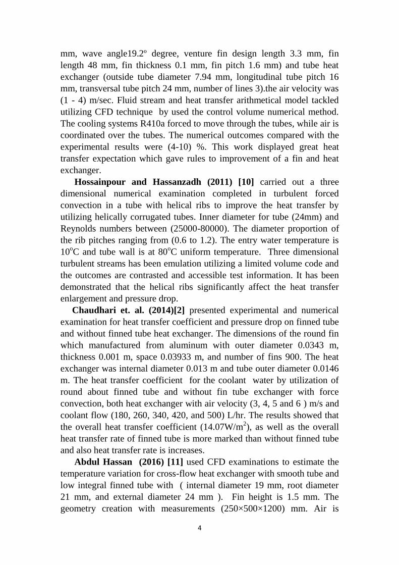
The laboratory device in this study consists of main parts which are
designed and manufactured with all the accessories and measuring
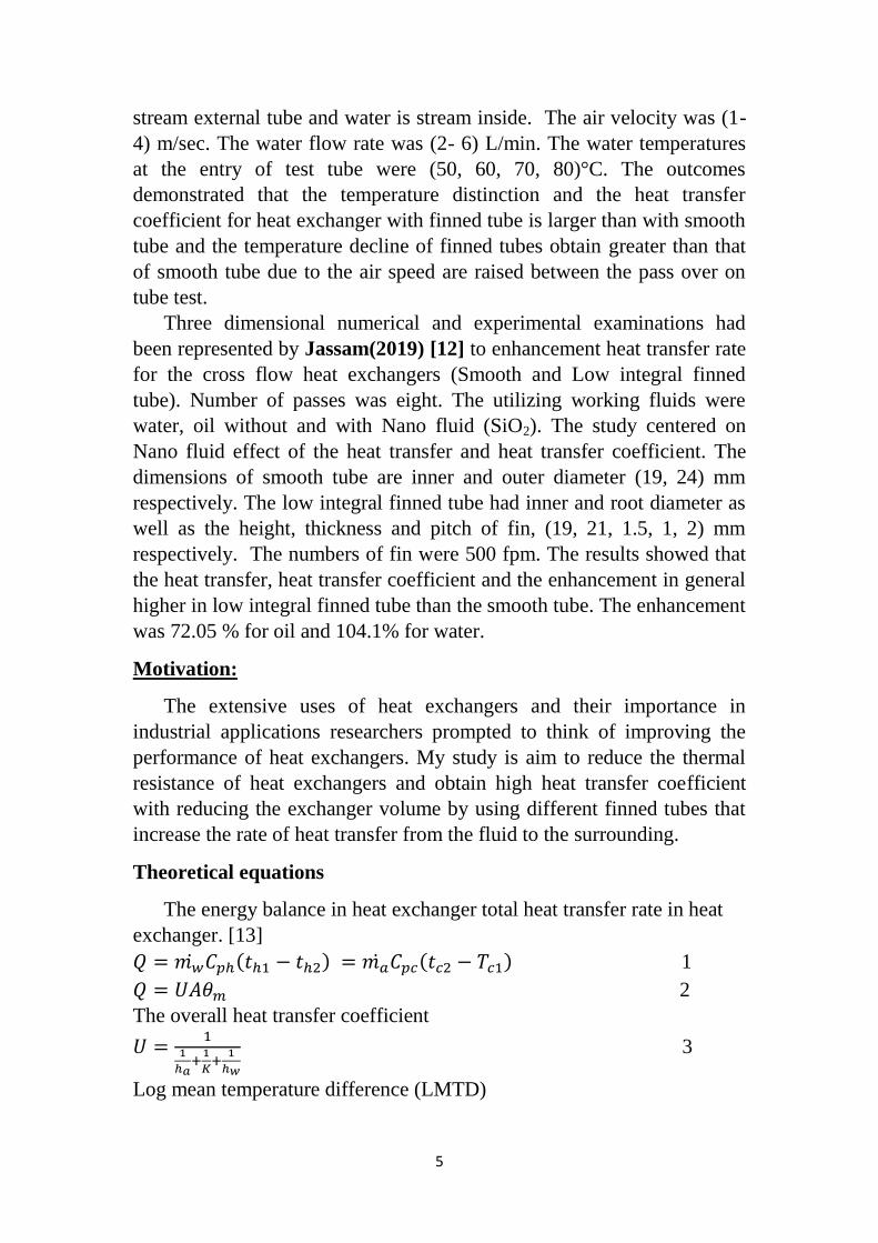
equipment as in figure (1). The test sections are (1200×250×500) mm as
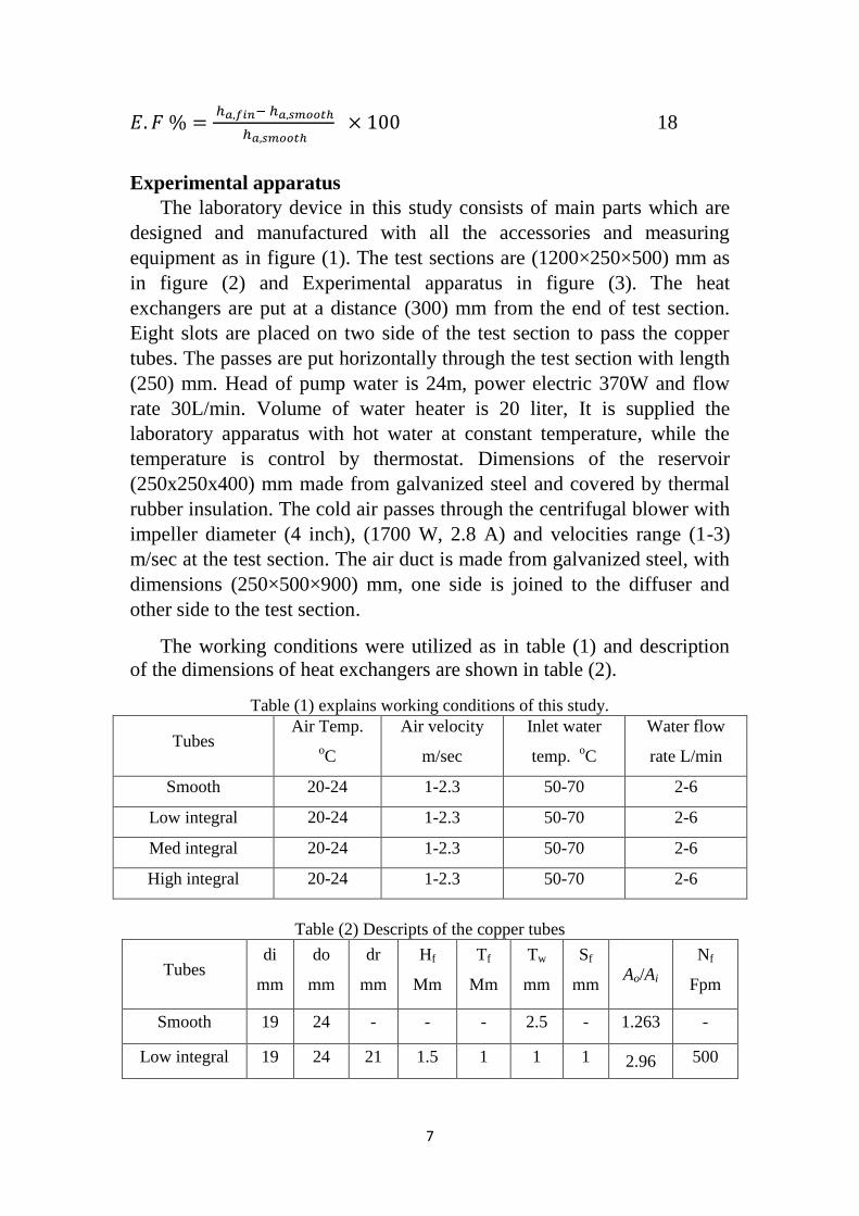
in figure (2) and Experimental apparatus in figure (3). The heat
exchangers are put at a distance (300) mm from the end of test section.
Eight slots are placed on two side of the test section to pass the copper
tubes. The passes are put horizontally through the test section with length
(250) mm. Head of pump water is 24m, power electric 370W and flow
rate 30L/min. Volume of water heater is 20 liter, It is supplied the
laboratory apparatus with hot water at constant temperature, while the
temperature is control by thermostat. Dimensions of the reservoir
(250x250x400) mm made from galvanized steel and covered by thermal
rubber insulation. The cold air passes through the centrifugal blower with
impeller diameter (4 inch), (1700 W, 2.8 A) and velocities range (1-3)
m/sec at the test section. The air duct is made from galvanized steel, with
dimensions (250×500×900) mm, one side is joined to the diffuser and
other side to the test section.
The working conditions were utilized as in table (1) and description
of the dimensions of heat exchangers are shown in table (2).
Table (1) explains working conditions of this study.
Tubes Air Temp.
oC
Air velocity
m/sec
Inlet water
temp. oC
Water flow
rate L/min
Smooth 20-24 1-2.3 50-70 2-6
Low integral 20-24 1-2.3 50-70 2-6
Med integral 20-24 1-2.3 50-70 2-6
High integral 20-24 1-2.3 50-70 2-6
Table (2) Descripts of the copper tubes
Tubes di
mm
do
mm
dr
mm
Hf
Mm
Tf
Mm
Tw
mm
Sf
mm Ao/Ai
Nf
Fpm
Smooth 19 24 - - - 2.5 - 1.263 -
Low integral 19 24 21 1.5 1 1 1 2.96 500
8
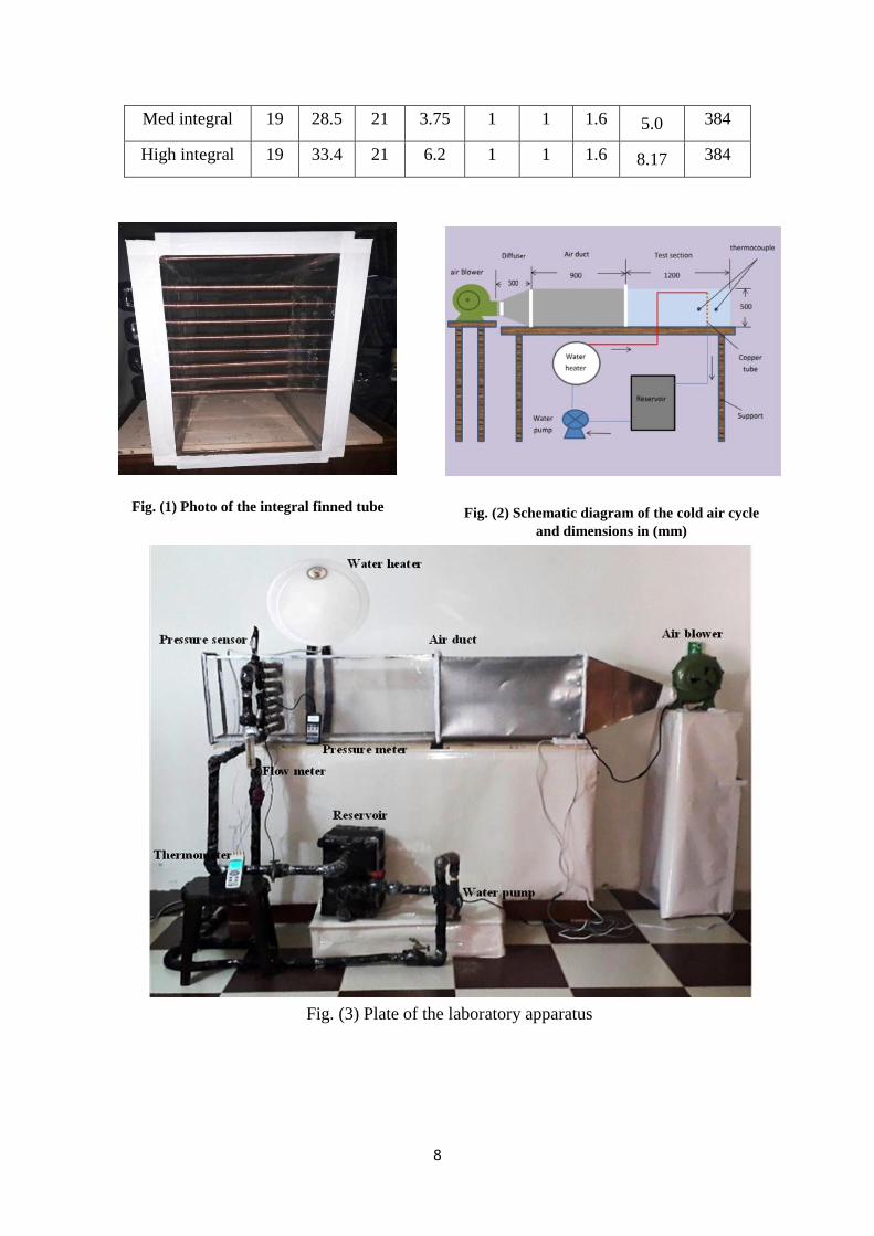
Med integral 19 28.5 21 3.75 1 1 1.6 5.0 384
High integral 19 33.4 21 6.2 1 1 1.6 8.17 384
Fig. (1) Photo of the integral finned tube Fig. (2) Schematic diagram of the cold air cycle
and dimensions in (mm)
Fig. (3) Plate of the laboratory apparatus
9
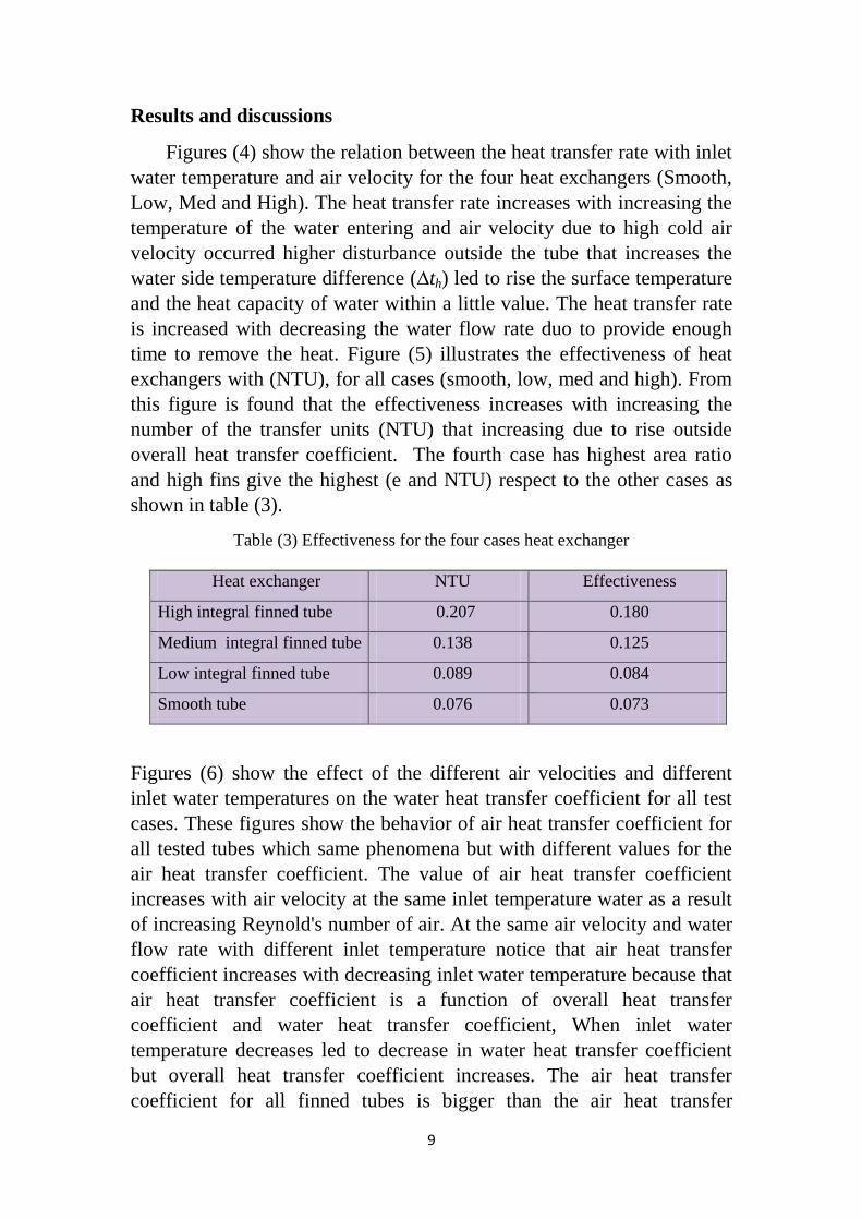
Results and discussions
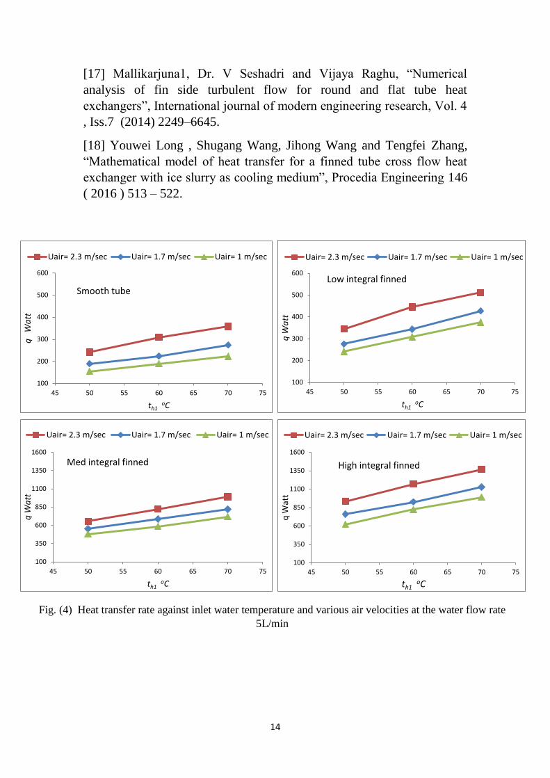
Figures (4) show the relation between the heat transfer rate with inlet
water temperature and air velocity for the four heat exchangers (Smooth,
Low, Med and High). The heat transfer rate increases with increasing the
temperature of the water entering and air velocity due to high cold air
velocity occurred higher disturbance outside the tube that increases the
water side temperature difference (∆th) led to rise the surface temperature
and the heat capacity of water within a little value. The heat transfer rate
is increased with decreasing the water flow rate duo to provide enough
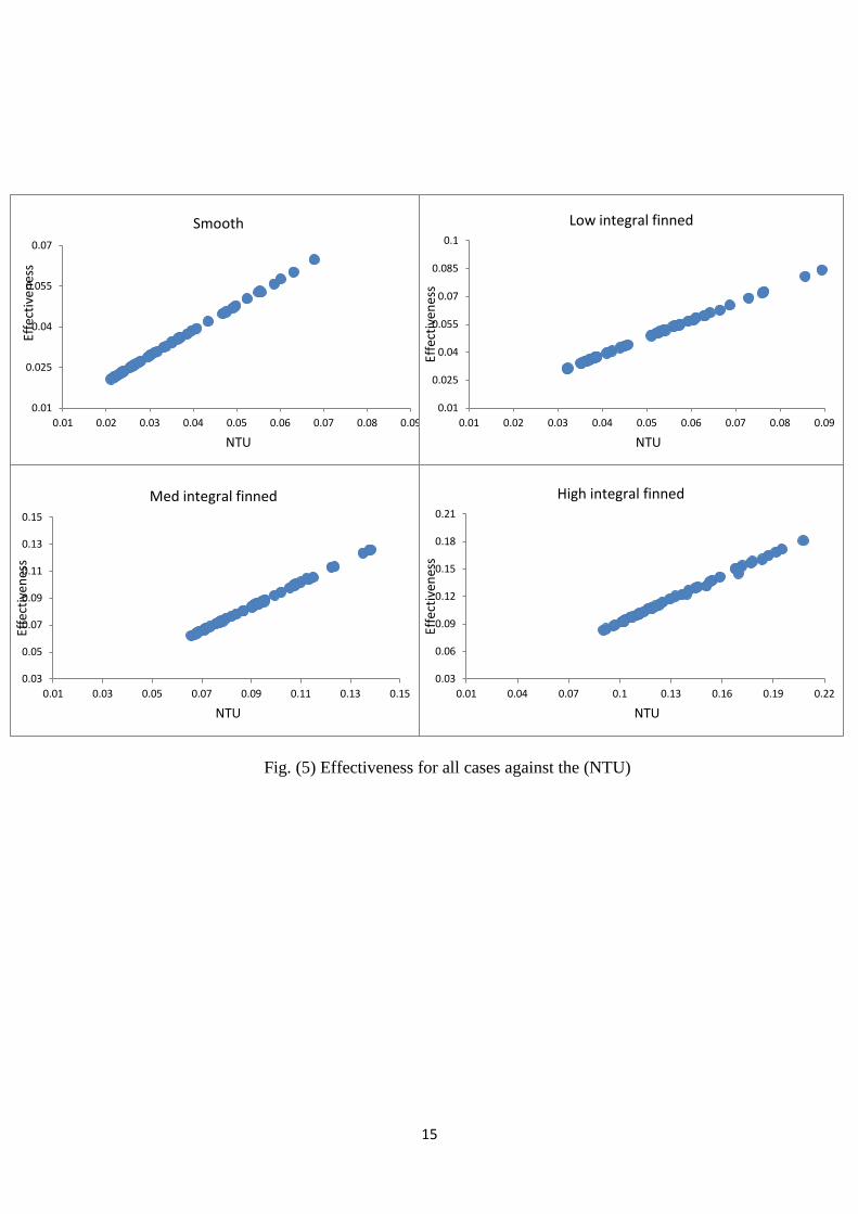
time to remove the heat. Figure (5) illustrates the effectiveness of heat
exchangers with (NTU), for all cases (smooth, low, med and high). From
this figure is found that the effectiveness increases with increasing the
number of the transfer units (NTU) that increasing due to rise outside
overall heat transfer coefficient. The fourth case has highest area ratio
and high fins give the highest (e and NTU) respect to the other cases as
shown in table (3).
Table (3) Effectiveness for the four cases heat exchanger
Heat exchanger NTU Effectiveness
High integral finned tube 0.207 0.180
Medium integral finned tube 0.138 0.125
Low integral finned tube 0.089 0.084
Smooth tube 0.076 0.073
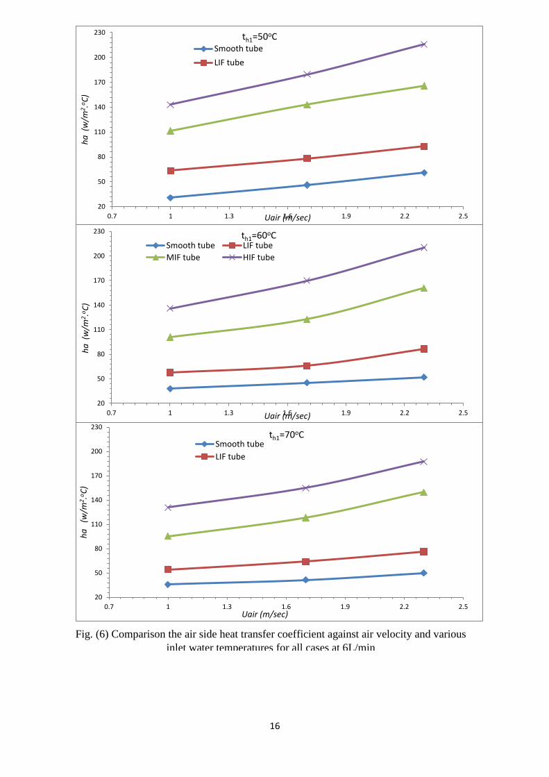
Figures (6) show the effect of the different air velocities and different
inlet water temperatures on the water heat transfer coefficient for all test
cases . These figures show the behavior of air heat transfer coefficient for
all tested tubes which same phenomena but with different values for the
air heat transfer coefficient. The value of air heat transfer coefficient
increases with air velocity at the same inlet temperature water as a result
of increasing Reynold's number of air. At the same air velocity and water
flow rate with different inlet temperature notice that air heat transfer
coefficient increases with decreasing inlet water temperature because that
air heat transfer coefficient is a function of overall heat transfer
coefficient and water heat transfer coefficient, When inlet water
temperature decreases led to decrease in water heat transfer coefficient
but overall heat transfer coefficient increases. The air heat transfer
coefficient for all finned tubes is bigger than the air heat transfer
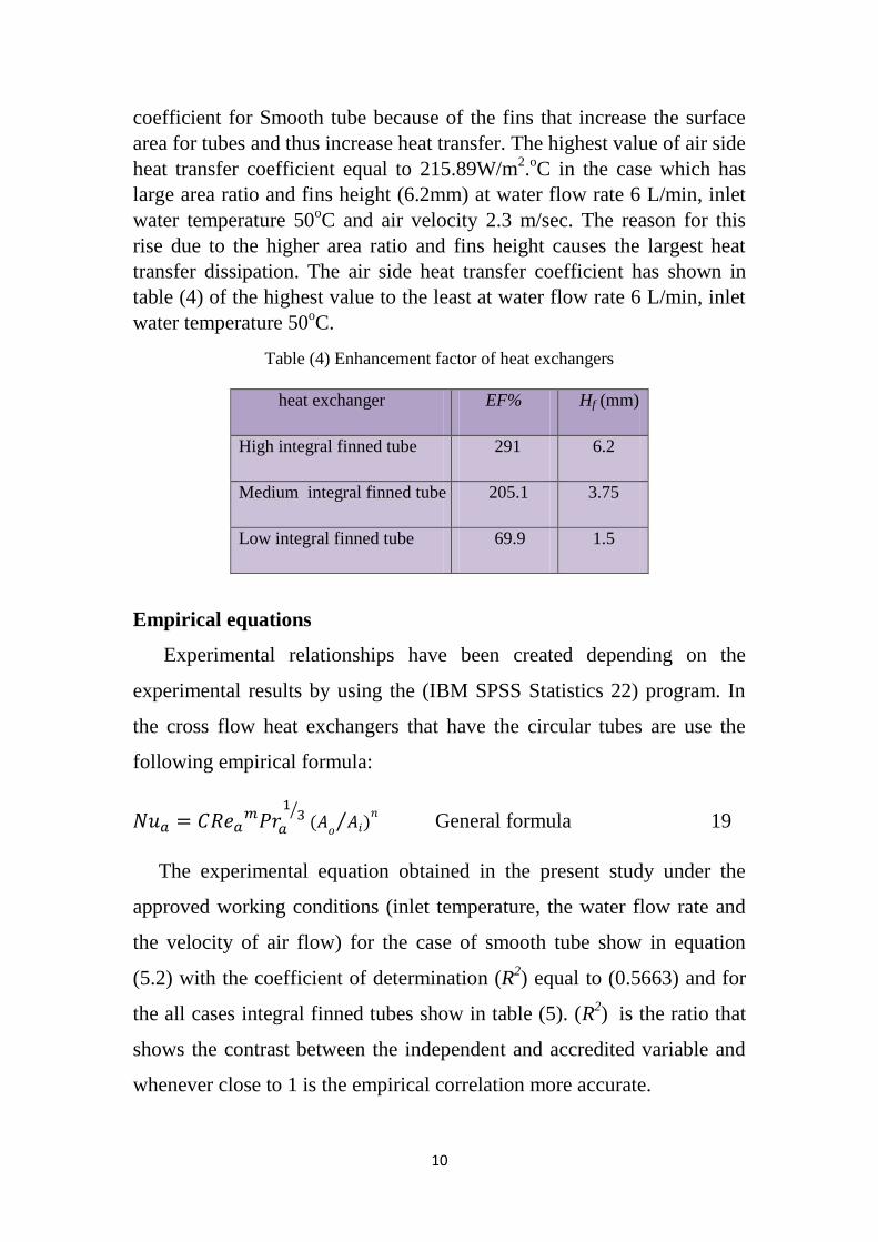
10
coefficient for Smooth tube because of the fins that increase the surface
area for tubes and thus increase heat transfer. The highest value of air side
heat transfer coefficient equal to 215.89W/m2.oC in the case which has
large area ratio and fins height (6.2mm) at water flow rate 6 L/min, inlet
water temperature 50oC and air velocity 2.3 m/sec. The reason for this
rise due to the higher area ratio and fins height causes the largest heat
transfer dissipation. The air side heat transfer coefficient has shown in
table (4) of the highest value to the least at water flow rate 6 L/min, inlet
water temperature 50oC.
Table (4) Enhancement factor of heat exchangers
heat exchanger EF% Hf (mm)
High integral finned tube 291 6.2
Medium integral finned tube 205.1 3.75
Low integral finned tube 69.9 1.5
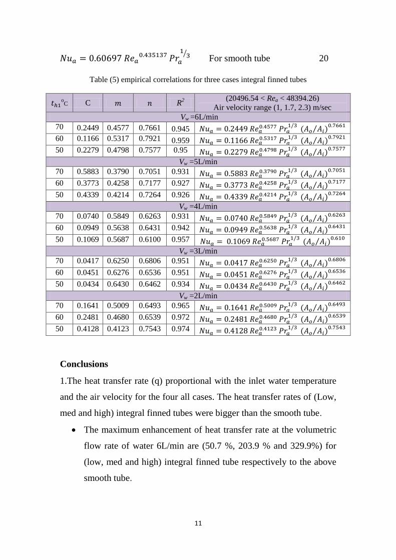
Empirical equations
Experimental relationships have been created depending on the
experimental results by using the (IBM SPSS Statistics 22) program. In
the cross flow heat exchangers that have the circular tubes are use the
following empirical formula:
⁄
⁄
General formula 19
The experimental equation obtained in the present study under the
approved working conditions (inlet temperature, the water flow rate and
the velocity of air flow) for the case of smooth tube show in equation
(5.2) with the coefficient of determination (R2) equal to (0.5663) and for
the all cases integral finned tubes show in table (5). (R2) is the ratio that
shows the contrast between the independent and accredited variable and
whenever close to 1 is the empirical correlation more accurate.
11
⁄ For smooth tube 20
Table (5) empirical correlations for three cases integral finned tubes
(20496.54 < Rea < 48394.26)
Air velocity range (1, 1.7, 2.3) m/sec R
2 C
oC
Vw =6L/min
⁄
0.945 0.7661 0.4577 0.2449 70
⁄
0.959 0.7921 0.5317 0.1166 60
⁄
0.95 0.7577 0.4798 0.2279 50
Vw =5L/min
⁄
0.931 0.7051 0.3790 0.5883 70
⁄
0.927 0.7177 0.4258 0.3773 60
⁄
0.926 0.7264 0.4214 0.4339 50
Vw =4L/min
⁄
0.931 0.6263 0.5849 0.0740 70
⁄
0.942 0.6431 0.5638 0.0949 60
⁄
0.957 0.6100 0.5687 0.1069 50
Vw =3L/min
⁄
0.951 0.6806 0.6250 0.0417 70
⁄
0.951 0.6536 0.6276 0.0451 60
⁄
0.934 0.6462 0.6430 0.0434 50
Vw =2L/min
⁄
0.965 0.6493 0.5009 0.1641 70
⁄
0.972 0.6539 0.4680 0.2481 60
⁄
0.974 0.7543 0.4123 0.4128 50
Conclusions
1.The heat transfer rate (q) proportional with the inlet water temperature
and the air velocity for the four all cases. The heat transfer rates of (Low,
med and high) integral finned tubes were bigger than the smooth tube.
The maximum enhancement of heat transfer rate at the volumetric
flow rate of water 6L/min are (50.7 %, 203.9 % and 329.9%) for
(low, med and high) integral finned tube respectively to the above
smooth tube.
12
The improvement in the heat transfer rate at inlet water temperature
70oC of the cases (low, medium),(low, high) and (med, high)
increases with the increasing of the height of the fins with
percentage (104.2% , 187.6% and 40.8%) respectively.
2- The effectiveness of the heat exchanger is directly proportional to
the number of heat transfer units. The high integral finned tube has
highest effectiveness value comparison with (low, med, smooth).
References
[1] Wolf, Franković, Viličić, Jurkowski and Bailly, “A numerical And
Experimental Analysis Of Heat Transfer In A Wavy Fin And Tube Heat
Exchanger”, Faculty of Engineering University of Rijeka, Vukovarska
58, HR-51 000 Rijeka, Croatia, Energy and the Environment (2006) 91-
101.
[2] Chaudhari, Subhedar and Patel, “Experimental Investigation of
Finned Tube Heat Exchanger”, M.Sc. thesis, University of Vadodara,
India, 2014.
[3] Pal Durgeshkumar K. and Sudhakar Umale, “Numerical investigation
on air side performance of fin and tube heat exchangers with different
types of fins”, International journal of thermal engineering vol.1, Iss.2
,(2015) 2395 – 0250.
[4] Muhammad Habib Zaid and S. Namasivayam, “Semi-Empirical
Model for Forced-Convection Condensation on Integral Finned-Tubes”,
Mechanical Engineering, Taylor’s University, Malaysia, EURECA 2013
pp.97-98.
[5] Ravi Kumar, H.K. Varma, Bikash and K.N.Agrawal, “Augmentation
of heat transfer during film wise condensation of steam and R-134a over
single horizontal finned tubes”, International Journal of heat and mass
transfer 45 (2002) 201-211.
[6] Ravi Kumar, Akhilesh Gupta and Sandeep Vishvakarma,
“Condensation of R-134a vapour over single horizontal integral fin tubes:
effect of fin height”, International Journal of Refrigeration 28 (2005)
428–435.
13
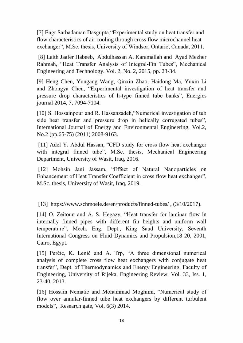
[7] Engr Sarbadaman Dasgupta,“Experimental study on heat transfer and
flow characteristics of air cooling through cross flow microchannel heat
exchanger”, M.Sc. thesis, University of Windsor, Ontario, Canada, 2011.
[8] Laith Jaafer Habeeb, Abdulhassan A. Karamallah and Ayad Mezher
Rahmah, “Heat Transfer Analysis of Integral-Fin Tubes”, Mechanical
Engineering and Technology. Vol. 2, No. 2, 2015, pp. 23-34.
[9] Heng Chen, Yungang Wang, Qinxin Zhao, Haidong Ma, Yuxin Li
and Zhongya Chen, “Experimental investigation of heat transfer and
pressure drop characteristics of h-type finned tube banks”, Energies
journal 2014, 7, 7094-7104.
[10] S. Hossainpour and R. Hassanzadeh,“Numerical investigation of tub
side heat transfer and pressure drop in helically corrugated tubes”,
International Journal of Energy and Environmental Engineering, Vol.2,
No.2 (pp.65-75) (2011) 2008-9163.
[11] Adel Y. Abdul Hassan, “CFD study for cross flow heat exchanger
with integral finned tube”, M.Sc. thesis, Mechanical Engineering
Department, University of Wasit, Iraq, 2016.
[12] Mohsin Jani Jassam, “Effect of Natural Nanoparticles on
Enhancement of Heat Transfer Coefficient in cross flow heat exchanger”,
M.Sc. thesis, University of Wasit, Iraq, 2019.
[13] https://www.schmoele.de/en/products/finned-tubes/ , (3/10/2017).
[14] O. Zeitoun and A. S. Hegazy, “Heat transfer for laminar flow in
internally finned pipes with different fin heights and uniform wall
temperature”, Mech. Eng. Dept., King Saud University, Seventh
International Congress on Fluid Dynamics and Propulsion,18-20, 2001,
Cairo, Egypt.
[15] Perčić, K. Lenić and A. Trp, “A three dimensional numerical
analysis of complete cross flow heat exchangers with conjugate heat
transfer”, Dept. of Thermodynamics and Energy Engineering, Faculty of
Engineering, University of Rijeka, Engineering Review, Vol. 33, Iss. 1,
23-40, 2013.
[16] Hossain Nematic and Mohammad Moghimi, “Numerical study of
flow over annular-finned tube heat exchangers by different turbulent
models”, Research gate, Vol. 6(3) 2014.
14
100
200
300
400
500
600
45 50 55 60 65 70 75
q
Wa
tt
th1 oC
Uair= 2.3 m/sec Uair= 1.7 m/sec Uair= 1 m/sec
Smooth tube
100
200
300
400
500
600
45 50 55 60 65 70 75
q W
att
th1 oC
Uair= 2.3 m/sec Uair= 1.7 m/sec Uair= 1 m/sec
Low integral finned
100
350
600
850
1100
1350
1600
45 50 55 60 65 70 75
q W
att
th1 oC
Uair= 2.3 m/sec Uair= 1.7 m/sec Uair= 1 m/sec
Med integral finned
100
350
600
850
1100
1350
1600
45 50 55 60 65 70 75
q W
att
th1 oC
Uair= 2.3 m/sec Uair= 1.7 m/sec Uair= 1 m/sec
High integral finned
Fig. (4) Heat transfer rate against inlet water temperature and various air velocities at the water flow rate
5L/min
[17] Mallikarjuna1, Dr. V Seshadri and Vijaya Raghu, “Numerical
analysis of fin side turbulent flow for round and flat tube heat
exchangers”, International journal of modern engineering research, Vol. 4
, Iss.7 (2014) 2249–6645.
[18] Youwei Long , Shugang Wang, Jihong Wang and Tengfei Zhang,
“Mathematical model of heat transfer for a finned tube cross flow heat
exchanger with ice slurry as cooling medium”, Procedia Engineering 146
( 2016 ) 513 – 522.
15
0.01
0.025
0.04
0.055
0.07
0.01 0.02 0.03 0.04 0.05 0.06 0.07 0.08 0.09
Effe
ctiv
enes
s
NTU
Smooth
0.01
0.025
0.04
0.055
0.07
0.085
0.1
0.01 0.02 0.03 0.04 0.05 0.06 0.07 0.08 0.09Ef
fect
iven
ess
NTU
Low integral finned
0.03
0.05
0.07
0.09
0.11
0.13
0.15
0.01 0.03 0.05 0.07 0.09 0.11 0.13 0.15
Effe
ctiv
enes
s
NTU
Med integral finned
0.03
0.06
0.09
0.12
0.15
0.18
0.21
0.01 0.04 0.07 0.1 0.13 0.16 0.19 0.22
Effe
ctiv
enes
s
NTU
High integral finned
Fig. (5) Effectiveness for all cases against the (NTU)
16
20
50
80
110
140
170
200
230
0.7 1 1.3 1.6 1.9 2.2 2.5
ha
(w
/m2 .
oC
)
Uair (m/sec)
th1=60oC Smooth tube LIF tube
MIF tube HIF tube
20
50
80
110
140
170
200
230
0.7 1 1.3 1.6 1.9 2.2 2.5
ha
(w
/m2 .
oC
)
Uair (m/sec)
th1=50oC
Smooth tube
LIF tube
20
50
80
110
140
170
200
230
0.7 1 1.3 1.6 1.9 2.2 2.5
ha
(w
/m2 .
oC
)
Uair (m/sec)
th1=70oC Smooth tube
LIF tube
Fig. (6) Comparison the air side heat transfer coefficient against air velocity and various
inlet water temperatures for all cases at 6L/min