EXPERIMENTAL INVESTIGATION OF CONVECTIVE BOILING IN … · However, the critical heat flux (CHF),...
10
Boudouh, M., et al.: Experimental Investigation of Convective Boiling in Mini-Channels ... THERMAL SCIENCE: Year 2017, Vol. 21, No. 1A, pp. 223-232 223 EXPERIMENTAL INVESTIGATION OF CONVECTIVE BOILING IN MINI-CHANNELS: COOLING APPLICATION OF THE PROTON EXCHANGE MEMBRANE FUEL CELLS by Mounir BOUDOUH a,b* , Mohamed SI AMEUR a , and Hasna LOUAHLIA-GUALOUS b a LESEI Laboratory, University of Batna, Batna, Algeria. b FEMTO-ST Institute, Micro Nano Systems & Science Department, CNRS, 90010, Belfort, France Original scientific paper DOI:10.2298/TSCI140521024B An experimental study of convective boiling heat transfer of water flowing in mini-channels at low flow rate is carried out with pure de-ionized water and cop- per-water nanofluids. A low concentration of copper nanometer-sized particles was used to enhance the boiling heat transfer. The aim is to characterize the sur- face temperature as well as to estimate the local heat transfer coefficients by using the inverse heat conduction problem. The inlet water temperature is fixed at 60 °C and mass fluxes operated in range of 212-573 kg/m²s in mini-channels of dimen- sions 500×2000 µm². The maximum heat flux investigated in the tests is limited to 7000 W/m². The results show that the surface temperature and the local heat transfer coefficient are dependent on the axial location and the adding of copper nanoparticles can significantly improve the heat transfer. Key words: two-phase flow, cooling, boiling, local heat transfer coefficient, nanofluid Introduction The cooling process based on miniaturization has attracted a great deal of attention in many applications, one can cite electronic devices, computing technologies and proton ex- change membrane fuel cells known as (PEM fuel cells). The comprehension of the main phe- nomenon related to the evacuation of heat energy peaks has lead to a better control and thus has helped to improve the performance of thermal systems. In this context, several research studies have been carried out, in both fundamental and industrial applications. The focus is to guaranty energy efficiency by finding a compromise between rapid high heat dissipation fluxes and cost, in such configurations of two phase cool- ing in order to ensure compactness, adequate, and efficient functionality. The modern cooling process has evolved towards to fluid phase change which is considered a promising approach compared to classical ones, (air and liquid) especially in fuel cells technology. Indeed, Thome [1] has reported the benefit of the two phase cooling, Garrity et al. [2] has concluded that the use of this method of cooling can be effective in the fuel cell system. * Corresponding author, e-mail: [email protected]; [email protected]
Transcript of EXPERIMENTAL INVESTIGATION OF CONVECTIVE BOILING IN … · However, the critical heat flux (CHF),...
Boudouh, M., et al.: Experimental Investigation of Convective Boiling in Mini-Channels ... THERMAL SCIENCE: Year 2017, Vol. 21, No. 1A, pp. 223-232 223
EXPERIMENTAL INVESTIGATION OF CONVECTIVE BOILING IN MINI-CHANNELS: COOLING APPLICATION
OF THE PROTON EXCHANGE MEMBRANE FUEL CELLS
by
Mounir BOUDOUH a,b*, Mohamed SI AMEUR a, and Hasna LOUAHLIA-GUALOUS b
a LESEI Laboratory, University of Batna, Batna, Algeria. b FEMTO-ST Institute, Micro Nano Systems & Science Department,
CNRS, 90010, Belfort, France
Original scientific paper DOI:10.2298/TSCI140521024B
An experimental study of convective boiling heat transfer of water flowing in mini-channels at low flow rate is carried out with pure de-ionized water and cop-per-water nanofluids. A low concentration of copper nanometer-sized particles was used to enhance the boiling heat transfer. The aim is to characterize the sur-face temperature as well as to estimate the local heat transfer coefficients by using the inverse heat conduction problem. The inlet water temperature is fixed at 60 °C and mass fluxes operated in range of 212-573 kg/m²s in mini-channels of dimen-sions 500×2000 µm². The maximum heat flux investigated in the tests is limited to 7000 W/m². The results show that the surface temperature and the local heat transfer coefficient are dependent on the axial location and the adding of copper nanoparticles can significantly improve the heat transfer.Key words: two-phase flow, cooling, boiling, local heat transfer coefficient,
nanofluid
Introduction
The cooling process based on miniaturization has attracted a great deal of attention in many applications, one can cite electronic devices, computing technologies and proton ex-change membrane fuel cells known as (PEM fuel cells). The comprehension of the main phe-nomenon related to the evacuation of heat energy peaks has lead to a better control and thus has helped to improve the performance of thermal systems.
In this context, several research studies have been carried out, in both fundamental and industrial applications. The focus is to guaranty energy efficiency by finding a compromise between rapid high heat dissipation fluxes and cost, in such configurations of two phase cool-ing in order to ensure compactness, adequate, and efficient functionality. The modern cooling process has evolved towards to fluid phase change which is considered a promising approach compared to classical ones, (air and liquid) especially in fuel cells technology. Indeed, Thome [1] has reported the benefit of the two phase cooling, Garrity et al. [2] has concluded that the use of this method of cooling can be effective in the fuel cell system.
* Corresponding author, e-mail: [email protected]; [email protected]
Boudouh, M., et al.: Experimental Investigation of Convective Boiling in Mini-Channels ... 224 THERMAL SCIENCE: Year 2017, Vol. 21, No. 1A, pp. 223-232
Then it appears in particular that the convective boiling heat transfer in micro-chan-nels or mini-channels holds great promise to replace air-cooling and water-cooling [3,4], indeed cooling by liquid-vapor phase change is an effective solution [5-7], useful for dissipating a high amount of heat while a uniform system temperature 80-100 °C is kept in the case of PEM fuel cells. It has also been noted that cooling systems using a coolant circulating in mini, or micro-channels (micro-ducts) is generally an innovative method which combines efficiency and compactness (compactness of approximately 20000 m2/m3) and which allows a better envi-ronmental protection (reduction of coolant fluid amount) and a high thermal dissipation which would reach 20000 W/m3 as reported by Lallemand [8].
In addition, on the microscale, the effect of gravity forces is surpassed by that of the surface tension forces, i. e., no stratified flow exists if the channel diameter is sufficiently small [9]. The Bond number gives the ratio of these forces for a channel of hydraulic diameter Dh:
( ) 2gBo L V hDρ ρ
σ−
= (1)
where ρL and ρV [kgm-3] are liquid density and vapor density, respectively, σ [Nm–1] – the surface tension, and g [ms–2] acceleration of gravity.
Cheng et al. [10] have proposed a classification of micro-channels based on Bond number: (1) micro-channel (Bo < 0.05), (2) mini-channel (0.05 < Bo < 3), and (3) macro-channel (Bo > 3), in our case (Bo = 0,089).
Studies have proven that the flow’s structure, and therefore the heat and mass transfer laws are significantly altered when the diameter of the channels is reduced to values lower than 3 mm [11, 12], In the case of boiling in micro-channels, many studies are performed on the visu-alization of flow regimes [13-16], in order to study the behavior of the flow regimes, the extent of pressure drop and the average heat exchange coefficients. However, the critical heat flux (CHF), or burnout refers to the sudden decrease in the heat transfer coefficient for a surface on which evap-oration or boiling is occurring, is a constraint that limits the power increase of operating cooling systems [17-19], indeed exceeding this heat flux causes the replacement of liquid adjacent to the heat transfer surface with a vapor blanket. This blanket acts as a barrier to heat flow from the heat dissipating device, resulting in possible failure (burnout) of the device and the identification of mechanisms and trigger areas of critical flux appears to be necessary [20] in order to act on the exchange surface and to increase the CHF. In this study, the main interests are the measure of both local temperatures and flux densities in mini-channels (application to PEM fuel cells) in order to reinforce the literature by this new laboratory investigation. The local surface temperature and heat flux are determined by solving inverse heat conduction problem (IHCP) using only wall tempera-ture measurements. Experimental results presented in this paper are treated only in steady state. The local heat transfer coefficient of each axial location along the channel length is determined from the local heat flux, qchannel,x, and local surface temperature, Ts,x:
channel,
,
xx
s x f
qh
T T=
− (2)
where Tf is the bulk mean temperature, it is equal to saturation temperature, Tsat, when boiling fluid is in the saturated state. qchannel,x and Ts,x are obtained by solving IHCP. The physical model for solving IHCP is defined by:
2 2
2 2 0T Tx y
∂ ∂+ =
∂ ∂ (3)

Boudouh, M., et al.: Experimental Investigation of Convective Boiling in Mini-Channels ... THERMAL SCIENCE: Year 2017, Vol. 21, No. 1A, pp. 223-232 225
where 0 ≤ x ≤ L, 0 ≤ y ≤ E, L and E are the length and the thickness of the plate, respectively.
( )0, 0T yx
∂=
∂ (4)
( ), 0T L yx
∂=
∂ (5)
( ),0 C CT x qy
λ ∂=
∂ (6)
( ) channel,, C xT x E qy
λ ∂=
∂ (7)
where y is the normal vector of the heat exchange surface, λC – the thermal conductivity of the Cu wall λC = 389 W/m2 K, and qchannel,x – the unknown surface heat flux. The determination of the local heat transfer coefficients can locate areas of low and high rates of voids. In a second step and in order to increase the heat transfer rate we have tested nanofluid, fluid in which nanome-ter-sized particles are loaded to increase its thermal properties [21-23].
Experimental apparatus and procedure
An experimental bench has been conceived and realized in this context. It is com-posed of: evaporator, micro-pump, and heat exchanger, the bench is instrumented with mi-cro-thermocouples and accuracy pressure sensors.
Figures 1(a) and 1(b) show a photograph and a schematic diagram of the experimental device fully designed to investigate the two-phase-cooling in simulated bipolar-plate of a PEM fuel cell.
Figure 1(a). Experimental apparatus
Condenser
Wattmeter
Test section (evaporator )
Refrigerationsystem
Micropump
Controledtemperature
bath
Acquisition system
Power supply
Figure 1(b). Schematic diagram of the experimental apparatus
LabVIEW data acquisition system
(1)
(8)
(7)
(6)(5)(4)
(3)
(2)
CCD camera
P1, T1, T2, T3, ................, P2
The experimental set-up consists of a micro-channels test section (evaporator) and a heat transfer fluid loop. The liquid is pumped from the tank (1) by a magnetic gear pump (3) fitted with a control microprocessor of MCP-Z standard type. The pump is also used as
Boudouh, M., et al.: Experimental Investigation of Convective Boiling in Mini-Channels ... 226 THERMAL SCIENCE: Year 2017, Vol. 21, No. 1A, pp. 223-232
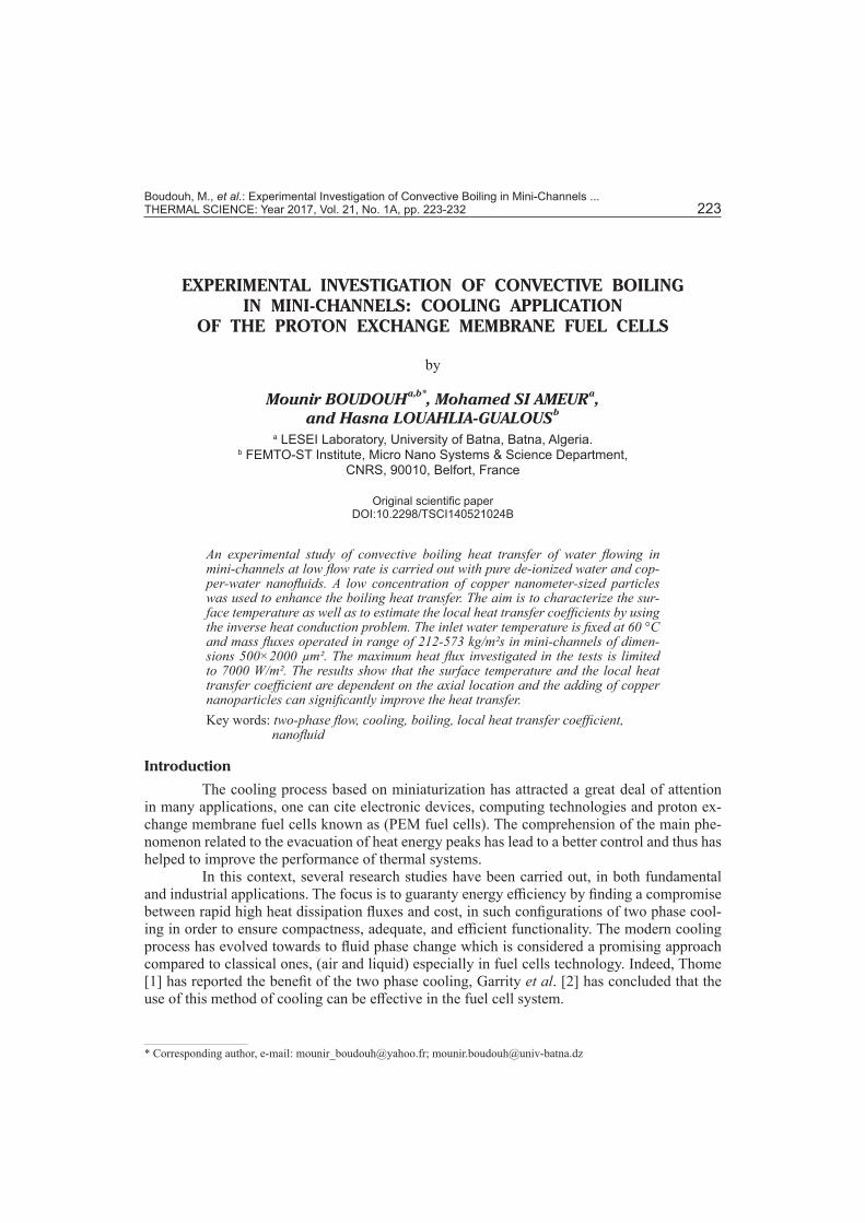
a flow meter. A 2 mm filter (2) is used to remove dust and micro-particles from the working fluid. The fluid passes from the tank to the test section (5). The mass flux is adjusted within the regulat-ing valves. The working liquid passes through the micro-channels test section to become a vapor and then enters into the heat exchanger (7) where it is cooled before returning to the tank (1). The tem-perature of the coolant fluid in the tank (1) is con-trolled using an electrical heater associated with a temperature controller. The test section (the evap-orator) is made of a Cu plate of 250 × 250 mm² and 10 mm thick. On one side of the test section, 50 rectangular mini-channels with hydraulic diam-eter of 800 μm are performed, figs. 2(a) and 2(b). These mini-channels of 160 mm of length are par-allel. On the opposite side of the exchange surface, a heating panel of a maximum power density of 7000 W/m² is placed. This panel is equipped with a PT100 sensor which keeps limiting the surface temperature level to 150 °C. It distributes heat evenly over the entire surface. A power supply is used to control the power imposed on the surface of the test section. The mini-channel surface is covered by a polycarbonate plate of 8 mm thick in order to visualize the coolant during its evolution in the mini-channels. All the plates forming the test section (polycarbonate plate, Cu plate, and the heater panel) are tightly jointed in a nested set of
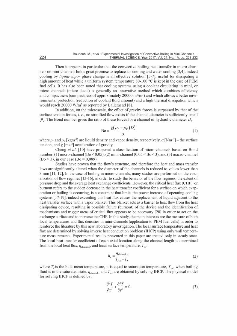
plates PTFE of 45 mm thick, which serve as a support and a thermal insulator. Chromel-Alu-mel micro-thermocouples (K-type 75 μm) are inserted into holes of 1 mm diameter on the back and the side of the plate, micro-thermocouples calibration is conducted by comparing the temperatures measured by microthermocouples and a precision sensor probes (±0.03 °C). The calibration procedure consists to maintain the micro-thermocouples at a known temperature
through a precision sensor probe and to record the micro-thermocouples responses using a LabVIEW data acquisition system. The procedure is repeated for different known temperatures. Figure 3 shows a comparison of temperatures measured by a micro-thermocouples and precision sensor probe.
Two mini-channels are instrumented by mi-cro-thermocouples as shown in fig. 4(a). Further-more, two micro-thermocouples are placed at the inlet and outlet of the test section in order to mea-sure the inlet and outlet temperature of the fluid. Two pressure sensors (4) and (6) Omega PX209 (0.25 % of accuracy) are installed to measure the
Figure 2(b). Construction of the minichannels in the test section
Channel depth in mm
Channel widthin mm
2 2 2 2
0.5
x
z
y
Fluid outlet
Channel N 41
Channel N 1
Fluid inlet
Figure 2(a). The Cu plate of the test section
Figure 3. Example of micro-thermocouple calibration curve
0
20
40
60
80
100
120
0 20 40 60 80 100 120
Prec
isio
n se
nso
r pro
be
[°C]
Microthermocouple [°C]
Boudouh, M., et al.: Experimental Investigation of Convective Boiling in Mini-Channels ... THERMAL SCIENCE: Year 2017, Vol. 21, No. 1A, pp. 223-232 227
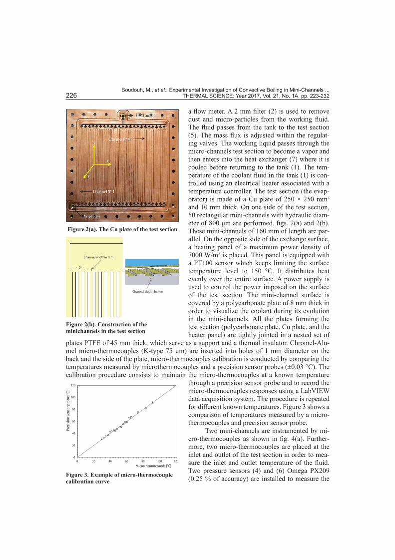
total pressure loss in the test section. The data acquisition is fully automated using the LabVIEW software and National Instruments hardware (8) which allows measurements in real time. Two mini-channels have been instrumented by micro-thermocouples that are inserted in the Cu plate at different depths and different positions, fig. 4(b), along the length of the channels. The first in-strumented channel (channel 1) is located at 2 mm from the edge of the test section, near the in-let of the coolant. The second one (channel 41), situated near the outlet of the fluid, is located at 160 mm from the edge of the test section. The micro-thermocouples are arranged at two or three levels deep from the exchange surface. Thus, for the first channel, 21 micro-thermocouples are placed at 0.5 mm, 5.5 mm, and 8 mm from the exchange surface. However, 17 micro-thermo-couples are placed at 0.5 mm and 5.5 mm from the exchange surface for the second channel. These micro-thermocouples allow us to measure the temperature at different depths of the plate.
Figure 4(b). Thermocouples locations in the first mini-channel
Figure 4(a). Bottom side of Cu test plate
Micro-thermocouples locations in the first channel
Fluid inletmanifold
Fluid outlet manifold
Mini-channel
Micro-thermocouplelocation at 0,5 mm
Micro-thermocouplelocation at 5 mm
Micro-thermocouplelocation at 8 mm
Results and interpretation
An experimental procedure is carried out to check the replicate results. Prior to test-ing, the micro-pump flow is made constant and the power output is set to a maximum of up to 280 W in order to activate boiling. Once this latter is reached, power is then reduced by decre-ments of 20 W, while recording the system temperatures and pressures.
Wall temperatures measured in steady- and unsteady-state
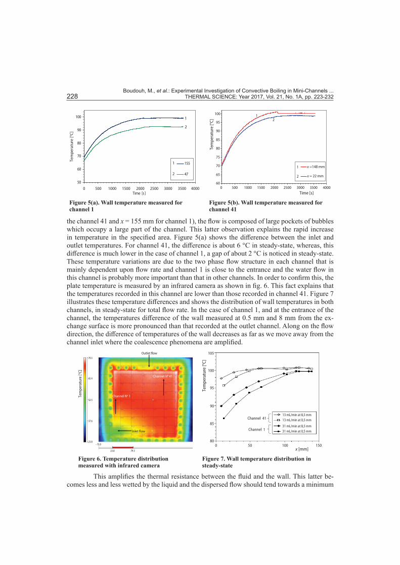
During trials, the temperature time change of the two wall channels 1 and 41 are measured. The test is conducted for a total flow rate of 35 mL/min and a supply power of 200 W. Figures 5(a), and 5(b) show the temperature time change for temperatures values given by micro-thermocouples placed at 0.5 mm from the surface exchange for channels 1 and 41. These changes are related to both abscissas x = 47 mm and x = 155 mm for channel 1 and to both abscissas x = 22 mm and x = 148 mm for channel 41. For readability reasons, only two curves are presented in these figures because the behavior is comparable to that obtained by curves given by other micro-thermocouples placed in the wall. Under transient conditions, the temperatures increase continuously with substantially the same temperature change with re-spect to time. In steady-state, temperatures stabilize and become substantially constant over time. It is noticed during testing that at given positions of the channel outlet (x = 148 mm for
Boudouh, M., et al.: Experimental Investigation of Convective Boiling in Mini-Channels ... 228 THERMAL SCIENCE: Year 2017, Vol. 21, No. 1A, pp. 223-232
the channel 41 and x = 155 mm for channel 1), the flow is composed of large pockets of bubbles which occupy a large part of the channel. This latter observation explains the rapid increase in temperature in the specified area. Figure 5(a) shows the difference between the inlet and outlet temperatures. For channel 41, the difference is about 6 °C in steady-state, whereas, this difference is much lower in the case of channel 1, a gap of about 2 °C is noticed in steady-state. These temperature variations are due to the two phase flow structure in each channel that is mainly dependent upon flow rate and channel 1 is close to the entrance and the water flow in this channel is probably more important than that in other channels. In order to confirm this, the plate temperature is measured by an infrared camera as shown in fig. 6. This fact explains that the temperatures recorded in this channel are lower than those recorded in channel 41. Figure 7 illustrates these temperature differences and shows the distribution of wall temperatures in both channels, in steady-state for total flow rate. In the case of channel 1, and at the entrance of the channel, the temperatures difference of the wall measured at 0.5 mm and 8 mm from the ex-change surface is more pronounced than that recorded at the outlet channel. Along on the flow direction, the difference of temperatures of the wall decreases as far as we move away from the channel inlet where the coalescence phenomena are amplified.
Figure 5(a). Wall temperature measured for channel 1
50
60
70
80
90
100
0 500 1000 1500 2000 2500 3000 3500 4000Time [s]
Tem
pera
ture
[°C]
155
47
1
2
1
2
Figure 5(b). Wall temperature measured for channel 41
60
65
70
75
80
85
90
95
100
0 500 1000 1500 2000 2500 3000 3500 4000
x =148 mm
x = 22 mm
Time [s]
Tem
pera
ture
[°C]
1
2
12
Figure 6. Temperature distribution measured with infrared camera
Inlet flow
Outlet flow
Channel No 41
Channel No 1Tem
pera
ture
[°C]
79.3
65.4
52.5
37.6
23.8–15.0
23.8 79.3
Figure 7. Wall temperature distribution in steady-state
Channel 41
Channel 1
13 mL/min at 8,5 mm13 mL/min at 0,5 mm
31 mL/min at 8,5 mm31 mL/min at 0,5 mm
105
100
95
90
85
800 50 100 150
x [mm]
Tem
pera
ture
[°C]
This amplifies the thermal resistance between the fluid and the wall. This latter be-comes less and less wetted by the liquid and the dispersed flow should tend towards a minimum
Boudouh, M., et al.: Experimental Investigation of Convective Boiling in Mini-Channels ... THERMAL SCIENCE: Year 2017, Vol. 21, No. 1A, pp. 223-232 229
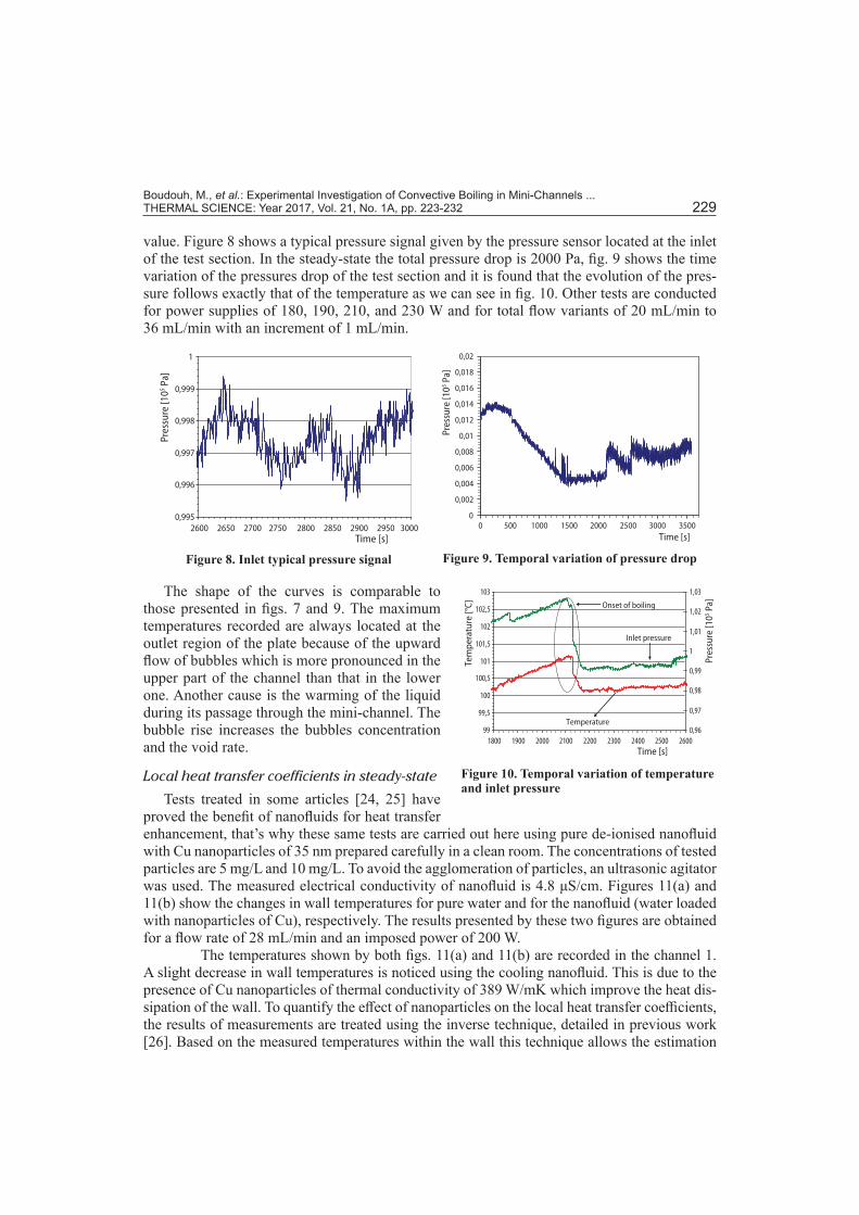
value. Figure 8 shows a typical pressure signal given by the pressure sensor located at the inlet of the test section. In the steady-state the total pressure drop is 2000 Pa, fig. 9 shows the time variation of the pressures drop of the test section and it is found that the evolution of the pres-sure follows exactly that of the temperature as we can see in fig. 10. Other tests are conducted for power supplies of 180, 190, 210, and 230 W and for total flow variants of 20 mL/min to 36 mL/min with an increment of 1 mL/min.
Figure 10. Temporal variation of temperature and inlet pressure
99
99,5
100
100,5
101
101,5
102
102,5
103
1800 1900 2000 2100 2200 2300 2400 2500 26000,96
0,97
0,98
0,99
1
1,01
1,02
1,03
Onset of boiling
Inlet pressure
Temperature
Time [s]
Tem
pera
ture
[°C]
Pres
sure
[105 P
a]
Figure 8. Inlet typical pressure signal
0,995
0,996
0,997
0,998
0,999
1
2600 2650 2700 2750 2800 2850 2900 2950 3000Time [s]
Pres
sure
[105 P
a]
Figure 9. Temporal variation of pressure drop
0
0,002
0,004
0,006
0,008
0,01
0,012
0,014
0,016
0,018
0,02
0 500 1000 1500 2000 2500 3000 3500Time [s]
Pres
sure
[105 P
a]
The shape of the curves is comparable to those presented in figs. 7 and 9. The maximum temperatures recorded are always located at the outlet region of the plate because of the upward flow of bubbles which is more pronounced in the upper part of the channel than that in the lower one. Another cause is the warming of the liquid during its passage through the mini-channel. The bubble rise increases the bubbles concentration and the void rate.
Local heat transfer coefficients in steady-state
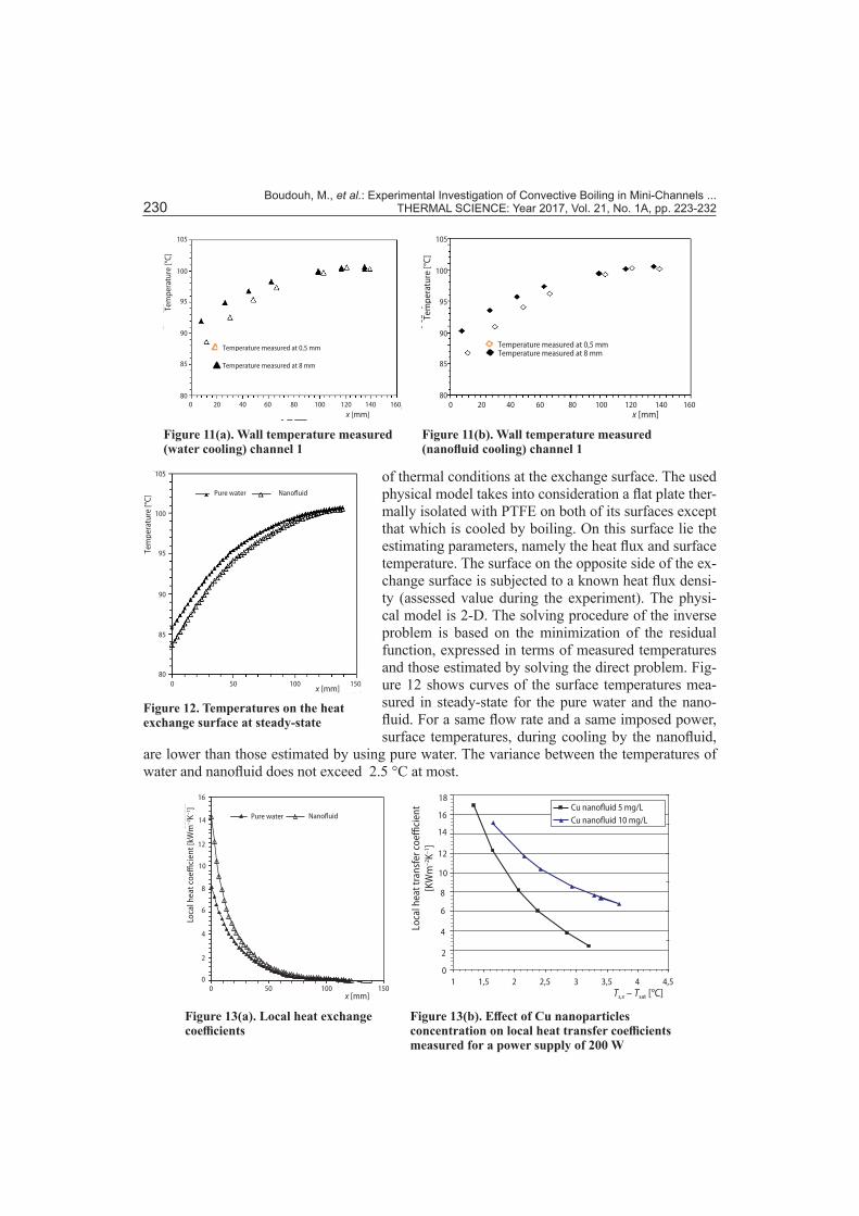
Tests treated in some articles [24, 25] have proved the benefit of nanofluids for heat transfer enhancement, that’s why these same tests are carried out here using pure de-ionised nanofluid with Cu nanoparticles of 35 nm prepared carefully in a clean room. The concentrations of tested particles are 5 mg/L and 10 mg/L. To avoid the agglomeration of particles, an ultrasonic agitator was used. The measured electrical conductivity of nanofluid is 4.8 μS/cm. Figures 11(a) and 11(b) show the changes in wall temperatures for pure water and for the nanofluid (water loaded with nanoparticles of Cu), respectively. The results presented by these two figures are obtained for a flow rate of 28 mL/min and an imposed power of 200 W.
The temperatures shown by both figs. 11(a) and 11(b) are recorded in the channel 1. A slight decrease in wall temperatures is noticed using the cooling nanofluid. This is due to the presence of Cu nanoparticles of thermal conductivity of 389 W/mK which improve the heat dis-sipation of the wall. To quantify the effect of nanoparticles on the local heat transfer coefficients, the results of measurements are treated using the inverse technique, detailed in previous work [26]. Based on the measured temperatures within the wall this technique allows the estimation
Boudouh, M., et al.: Experimental Investigation of Convective Boiling in Mini-Channels ... 230 THERMAL SCIENCE: Year 2017, Vol. 21, No. 1A, pp. 223-232
of thermal conditions at the exchange surface. The used physical model takes into consideration a flat plate ther-mally isolated with PTFE on both of its surfaces except that which is cooled by boiling. On this surface lie the estimating parameters, namely the heat flux and surface temperature. The surface on the opposite side of the ex-change surface is subjected to a known heat flux densi-ty (assessed value during the experiment). The physi-cal model is 2-D. The solving procedure of the inverse problem is based on the minimization of the residual function, expressed in terms of measured temperatures and those estimated by solving the direct problem. Fig-ure 12 shows curves of the surface temperatures mea-sured in steady-state for the pure water and the nano-fluid. For a same flow rate and a same imposed power, surface temperatures, during cooling by the nanofluid,
are lower than those estimated by using pure water. The variance between the temperatures of water and nanofluid does not exceed 2.5 °C at most.
Figure 11(a). Wall temperature measured (water cooling) channel 1
Temperature measured at 0,5 mm
Temperature measured at 8 mm
x [mm]
Tem
pera
ture
[°C]
0 20 40 60 80 100 120 140 16080
85
90
95
100
105
Figure 11(b). Wall temperature measured (nanofluid cooling) channel 1
Temperature measured at 0,5 mmTemperature measured at 8 mm
0 20 40 60 80 100 120 140 160x [mm]
Tem
pera
ture
[°C]
80
85
90
95
100
105
Figure 12. Temperatures on the heat exchange surface at steady-state
Pure water Nanofluid
Tem
pera
ture
[°C]
0 50 100 150x [mm]
105
100
95
90
85
80
Figure 13(a). Local heat exchange coefficients
0
10
20
30
40
50
60
70
80
Mill
iers
x en mm
h lo
cal e
n kW
/m²K
Ea u pure Na nofluidePure water Nanofluid
2
4
6
8
10
12
14
16
00 50 100 150
x [mm]
Loca
l hea
t coe
ffici
ent [
kWm
–2K–1
]
Figure 13(b). Effect of Cu nanoparticles concentration on local heat transfer coefficients measured for a power supply of 200 W
2000
2500
3000
3500
4000
4500
5000
5500
6000
6500
1 1,5 2 2,5 3 3,5 4 4,5Ts,x – Tsat [°C]
0
1000
2000
3000
4000
5000
6000
Cu nanofluid 5 mg/LCu nanofluid 10 mg/L
18
16
14
12
10
8
6
4
2
0
Loca
l hea
t tra
nsfe
r coe
ffici
ent
[KW
m–2
K–1]
Boudouh, M., et al.: Experimental Investigation of Convective Boiling in Mini-Channels ... THERMAL SCIENCE: Year 2017, Vol. 21, No. 1A, pp. 223-232 231
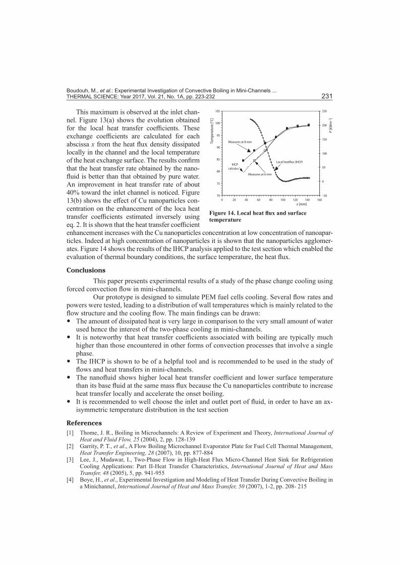
This maximum is observed at the inlet chan-nel. Figure 13(a) shows the evolution obtained for the local heat transfer coefficients. These exchange coefficients are calculated for each abscissa x from the heat flux density dissipated locally in the channel and the local temperature of the heat exchange surface. The results confirm that the heat transfer rate obtained by the nano-fluid is better than that obtained by pure water. An improvement in heat transfer rate of about 40% toward the inlet channel is noticed. Figure 13(b) shows the effect of Cu nanoparticles con-centration on the enhancement of the loca heat transfer coefficients estimated inversely using eq. 2. It is shown that the heat transfer coefficient enhancement increases with the Cu nanoparticles concentration at low concentration of nanoapar-ticles. Indeed at high concentration of nanoparticles it is shown that the nanoparticles agglomer-ates. Figure 14 shows the results of the IHCP analysis applied to the test section which enabled the evaluation of thermal boundary conditions, the surface temperature, the heat flux.
Conclusions
This paper presents experimental results of a study of the phase change cooling using forced convection flow in mini-channels.
Our prototype is designed to simulate PEM fuel cells cooling. Several flow rates and powers were tested, leading to a distribution of wall temperatures which is mainly related to the flow structure and the cooling flow. The main findings can be drawn:
y The amount of dissipated heat is very large in comparison to the very small amount of water used hence the interest of the two-phase cooling in mini-channels.
y It is noteworthy that heat transfer coefficients associated with boiling are typically much higher than those encountered in other forms of convection processes that involve a single phase.
y The IHCP is shown to be of a helpful tool and is recommended to be used in the study of flows and heat transfers in mini-channels.
y The nanofluid shows higher local heat transfer coefficient and lower surface temperature than its base fluid at the same mass flux because the Cu nanoparticles contribute to increase heat transfer locally and accelerate the onset boiling.
y It is recommended to well choose the inlet and outlet port of fluid, in order to have an ax-isymmetric temperature distribution in the test section
References[1] Thome, J. R., Boiling in Microchannels: A Review of Experiment and Theory, International Journal of
Heat and Fluid Flow, 25 (2004), 2, pp. 128-139[2] Garrity, P. T., et al., A Flow Boiling Microchannel Evaporator Plate for Fuel Cell Thermal Management,
Heat Transfer Engineering, 28 (2007), 10, pp. 877-884[3] Lee, J., Mudawar, I., Two-Phase Flow in High-Heat Flux Micro-Channel Heat Sink for Refrigeration
Cooling Applications: Part II-Heat Transfer Characteristics, International Journal of Heat and Mass Transfer, 48 (2005), 5, pp. 941-955
[4] Boye, H., et al., Experimental Investigation and Modeling of Heat Transfer During Convective Boiling in a Minichannel, International Journal of Heat and Mass Transfer, 50 (2007), 1-2, pp. 208- 215
Figure 14. Local heat flux and surface temperature
70
75
80
85
90
95
100
105
0 20 40 60 80 100 120 140 160–50
0
50
100
150
200
250
Mil
lier
s
Densité de flux thermique local (PICC) en kW
Mesures à 6 mm
Mesures à 8 mm
Calculs PICC
P [k
Wm
–2]
Local heatflux (IHCP)
Measures at 8 mm
Measures at 6 mm
IHCP calculus
x [mm]
Tem
pera
ture
[°C]
Boudouh, M., et al.: Experimental Investigation of Convective Boiling in Mini-Channels ... 232 THERMAL SCIENCE: Year 2017, Vol. 21, No. 1A, pp. 223-232
[5] Manglik, R. M., On the Advancements in Boiling Two-Phase Flow Heat Transfer, and Interfacial Phe-nomena, Journal of Heat Transfer, 128 (2006), 12, pp. 1237-1242
[6] Bowers, M. B., Mudawar, I., High-Flux Boiling in Low-Flow Rate, Low-Pressure Drop Mini-Channel and Microchannel Heat Sinks, International Journal of Heat and Mass Transfer, 37 (1994), 2, pp. 321-332
[7] Balakarishnan, R., et al., Flow Boiling Het Transfer Coefficient of R-134/R-290/R-600a Mixture in Smooth Horizontal Tube, Thermal Science, 12 (2008), 3, pp. 33-44
[8] Lallemand, M., Report Integrated Research Project 8.2, Energy Program, France 2004[9] Dupont, V., Thome, J. R., Evaporation in Microchannels: Influence of the Channel Diameter on Heat
Transfer, Microfluidics and Nanofluidics, 1 (2005), 2, pp. 119-127[10] Cheng, P., et al., Phase-Change Heat Transfer in Microsystems, Journal of Heat Transfer, 129 (2007), 2,
pp. 101-107[11] Cubaud, T., et al., Two-Phase Flow in Microchannels with Surface Modifications, Fluid Dynamics Re-
search, 38 (2006), 11, pp. 772-786[12] Harirchian, T., Garimella, S. V., Effects of Channel Dimension, Heat Flux, and Mass Flux on Flow Boiling
Regimes in Microchannels, International Journal of Multiphase Flow, 35 (2009), 4, pp. 349-362[13] Owhaib, W., et al., A Visualization Study of Bubble Behavior in Saturated Flow Boiling through a Vertical
Mini-Tube, Heat Transfer Engineering, 28 (2007), 10, pp. 852-860[14] Kandlikar, S. G., et al., High-Speed Photographic Observation of Flow Boiling of Water in Parallel
Mini-Channels, Proceedings, 35th National Heat Transfer Conference, Anaheim, Cal., USA, 2001[15] Kandlikar, S. G., et al., Experimental Evaluation of Pressure Drop Elements and Fabricated Nucleation
Sites for Stabilizing Flow Boiling in Minichannels and Microchannels, Proceedings, 3rd International Conference on Microchannels and Minichannels, Toronto, Canada, 2005
[16] Weilin, Q., Mudawar, I., Measurement and Prediction of Pressure Drop in Two Phase Micro Channel Heat Sinks, Internationl Journal of Heat and Mass Transfer, 46 (2003), 15, pp. 2737-2753
[17] Bergles, A. E, Kandlikar, S. G., On the Nature of Critical Heat Flux in Microchannels, Journal of Heat Transfer, 127 (2005), 1, pp. 101-107
[18] Lazarek, G. M., Black, S. H., Evaporative Heat Transfer, Pressure Drop and Critical Heat Flux in Small Vertical Tube With R-113, International Journal of Heat and Mass Transfer, 25 (1982), 7, pp. 945-960
[19] Revellin, R., et al., Status of Prediction Methods for Critical Heat Fluxes in Mini and Microchannels, International Journal of Heat and Fluid Flow, 30 (2009), 5, pp. 983-992
[20] Hall, D. D., Mudawar, I., Critical Heat Flux (CHF) for Water Flow in Tubes-I. Compilation and Assess-ment of World CHF Data, International Journal of Heat and Mass Transfer, 43 (2000), 24, pp. 2573-2604
[21] Roy, G., et al., Heat Transfer and Fluid Flow in Laminar Radial Flow Cooling Systems, Journal of Ther-mal Science, 14 (2005), 4, pp. 362-367
[22] Maiga, S. E., et al., Heat Transfer Enhancement by Using Nanofluids in Forced Convection Flows, Inter-national Journal of Heat and Fluid Flow, 26 (2005), 4, pp. 530-546
[23] Shanthi, R., et al., Heat Transfer Enhancement Using Nanofluids an Overview, Thermal Science, 16 (2012), 2, pp. 423-444
[24] Zhou, D. W., Heat Transfer Enhancement of Cooper Nanofluid with Acoustic Cavitation, Journal of Heat and Mass Transfer, 47 (2004), 14-16, pp. 3109-3117
[25] Boudouh, M., et al., Local Convective Boiling Heat Transfer and Pressure Drop of Nanofluid in Narrow Rectangular Channels, Applied Thermal Engineering, 30 (2010), 17-18, pp. 2619-2631
[26] Louahlia-Gualous, H., et al., The Inverse Estimation of the Local Heat Transfer Coefficient in Falling Film Evaporation, Inverse Problem in Science and Engineering Journal, 12 (2004), 1, pp. 29-43
Paper submitted: May 21, 2014Paper revised: January 19, 2015Paper accepted: February 8, 2015
© 2017 Society of Thermal Engineers of SerbiaPublished by the Vinča Institute of Nuclear Sciences, Belgrade, Serbia.
This is an open access article distributed under the CC BY-NC-ND 4.0 terms and conditions