Experimental Investigation and Modelling of Spread Slab...
10
Experimental Investigation and Modelling of Spread Slab Beam Bridges Tevfik Terzioglu Postdoctoral Researcher, Texas A&M Transportation Institute, College Station, TX Mary Beth D. Hueste Professor, Texas A&M University, College Station, TX John B. Mander Professor, Texas A&M University, College Station, TX Abstract A new bridge system was recently developed for short span bridges in low clearance areas using the same concept as spread box beam bridges in which the standard TxDOT slab beams are spaced apart. This paper presents an evaluation of spread slab beam bridges in terms of design, constructability, and performance. Forty-four bridge geometries were designed using standard TxDOT slab beam types to determine the feasible design space. One of the most aggressive geometries with widely spaced slab beams was constructed at full-scale. The bridge was tested under static and dynamic vehicular loads to obtain important insight into its behaviour under vehicular load. The load distribution behaviour was investigated during field testing and the measured data was utilized to validate computational modelling techniques. Based on the research findings, it was concluded that spread slab beam bridges that utilize precast concrete panels with a cast-in-place concrete deck provide a viable construction method for short-span bridges. The desired performance was achieved for in-service loading. Experimental live load distribution factors (LLDFs) were evaluated and LLDF equations for spread box beams were reviewed for applicability to spread slab beams. The measured response under dynamic loads was larger compared to the static values. 1 Introduction Precast prestressed concrete girders have been used effectively to provide economical bridge superstructures for short to medium spans [1]. The majority of these prestressed concrete bridges are simply supported spans where the cast-in- place (CIP) deck slab is made composite with precast pretensioned girders. The Texas Department of Transportation (TxDOT) often uses prestressed concrete slab beam bridges as a common alternative for short span bridges. The conventional approach consists of placing the slab beams side-by-side and casting a 127 mm CIP reinforced concrete deck on top of the slab beams. This shallow bridge
Transcript of Experimental Investigation and Modelling of Spread Slab...
Experimental Investigation and Modelling of
Spread Slab Beam Bridges
Tevfik Terzioglu
Postdoctoral Researcher,
Texas A&M
Transportation Institute,
College Station, TX
Mary Beth D. Hueste
Professor, Texas A&M
University, College
Station, TX
John B. Mander
Professor, Texas A&M
University, College
Station, TX
Abstract A new bridge system was recently developed for short span bridges in
low clearance areas using the same concept as spread box beam bridges in which
the standard TxDOT slab beams are spaced apart. This paper presents an evaluation
of spread slab beam bridges in terms of design, constructability, and performance.
Forty-four bridge geometries were designed using standard TxDOT slab beam types
to determine the feasible design space. One of the most aggressive geometries with
widely spaced slab beams was constructed at full-scale. The bridge was tested under
static and dynamic vehicular loads to obtain important insight into its behaviour
under vehicular load. The load distribution behaviour was investigated during field
testing and the measured data was utilized to validate computational modelling
techniques. Based on the research findings, it was concluded that spread slab beam
bridges that utilize precast concrete panels with a cast-in-place concrete deck
provide a viable construction method for short-span bridges. The desired
performance was achieved for in-service loading. Experimental live load
distribution factors (LLDFs) were evaluated and LLDF equations for spread box
beams were reviewed for applicability to spread slab beams. The measured response
under dynamic loads was larger compared to the static values.
1 Introduction
Precast prestressed concrete girders have been used effectively to provide
economical bridge superstructures for short to medium spans [1]. The majority of
these prestressed concrete bridges are simply supported spans where the cast-in-
place (CIP) deck slab is made composite with precast pretensioned girders. The
Texas Department of Transportation (TxDOT) often uses prestressed concrete slab
beam bridges as a common alternative for short span bridges. The conventional
approach consists of placing the slab beams side-by-side and casting a 127 mm CIP
reinforced concrete deck on top of the slab beams. This shallow bridge

2
superstructure system is attractive in locations where there is a low clearance below
the bridge. However, conventional slab beam bridges are more expensive compared
to standard I-girder bridges that are constructed using PCPs as stay-in-place
formwork between girders. To address this issue TxDOT has shown interest in
exploring new bridge systems that may provide more economical solutions for
short-span bridges. One such idea that has been developed by TxDOT is to modify
the current short span bridge design that uses immediately adjacent prestressed
concrete slab beams shown in Figure 1(b). The proposed solution is to spread out
the slab beams and to use a conventional topped panelized deck as shown in
Figure 1(a). It is anticipated that spread slab beam bridges will result in a possible
reduction in the overall bridge cost while providing another design alternative for
short span bridges.
(a) Spread slab beam bridge (b) Conventional slab beam bridge
Figure 1. Slab beam bridge cross-section
Viable spread slab beam bridge geometries were chosen according to practical
beam spacing and bridge width criteria. A total of 44 spread slab beams were
designed using the maximum permissible concrete design strength. One of the
preliminary designs with a large eccentricity due to a wide beam spacing and a
relatively longer span length was chosen for the full-scale bridge construction and
field testing. A full-scale spread slab beam bridge was constructed and field tested
at the Texas A&M University Riverside Campus. The measured response was then
used to validate computational finite element method (FEM) and grillage analysis
modeling techniques to evaluate the accuracy of alternative methods for modeling
spread slab beam bridges.
One key issue for developing a new bridge superstructure system is identifying
appropriate LLDFs. Although there are other viable methods of analysis for
calculating moment and shear demands, such as the grillage and the FEM, bridge
design engineers prefer using approximate LDFs that are provided in the American
Association of State Highway and Transportation Officials (AASHTO) Load and
Resistance Factor Design (LRFD) Bridge Design Specifications [2] for several
bridge types. There are no approximate formulas provided for spread slab beams;
part of this study is to determine whether the spread box beam formulas might also
be applicable to spread slab beams.
3
2 Full-Scale Bridge Construction and Field Testing
A detailed parametric study was conducted to investigate the potential benefits of
using spread slab beam bridges and to develop preliminary designs for alternative
design parameters and geometries. The preliminary designs were carried out
following the AASHTO LRFD Specifications and TxDOT Bridge Design Manual
[3]. All geometric combinations listed in Table 1 were investigated to determine the
maximum span length versus number of strands provided. More detailed design
procedures may be found in [4, 5]. For the parametric study, each slab beam was
designed based on a given number of strands. The maximum achievable span
lengths for eight different limit states were calculated at each step. The considered
limit states include tension and compression stress limits at release, at the time of
deck placement, and at service; along with ultimate flexural strength and the live
load deflection limit at service.
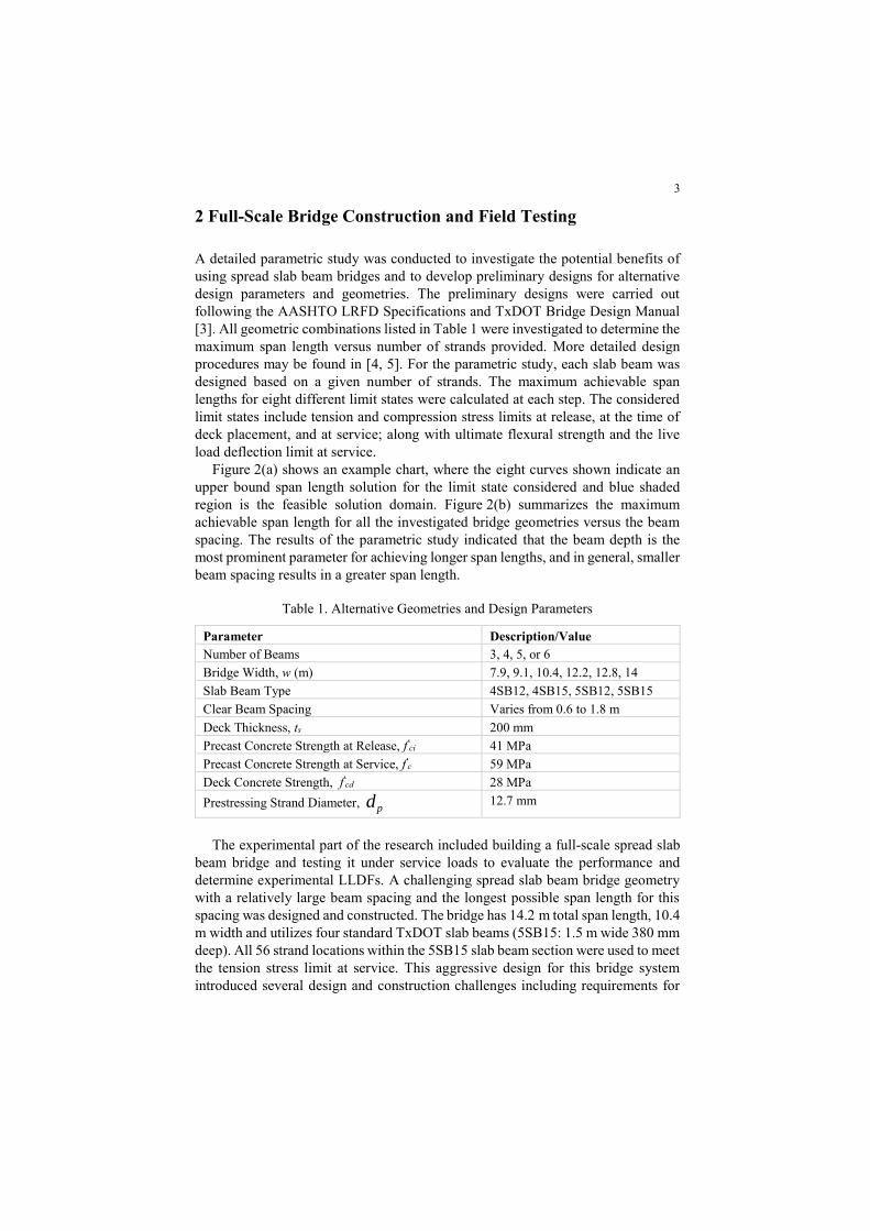
Figure 2(a) shows an example chart, where the eight curves shown indicate an
upper bound span length solution for the limit state considered and blue shaded
region is the feasible solution domain. Figure 2(b) summarizes the maximum
achievable span length for all the investigated bridge geometries versus the beam
spacing. The results of the parametric study indicated that the beam depth is the
most prominent parameter for achieving longer span lengths, and in general, smaller
beam spacing results in a greater span length.
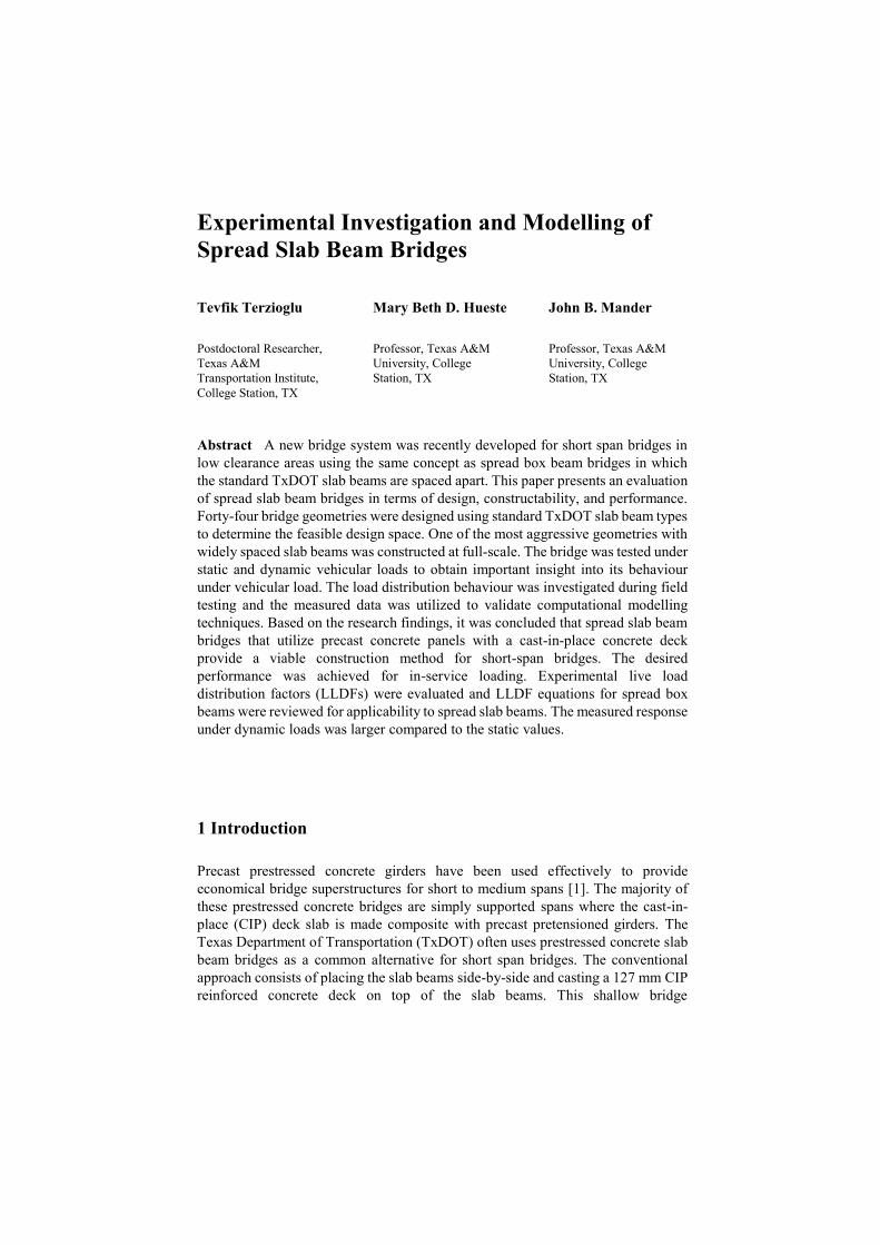
Table 1. Alternative Geometries and Design Parameters
Parameter Description/Value
Number of Beams 3, 4, 5, or 6
Bridge Width, w (m) 7.9, 9.1, 10.4, 12.2, 12.8, 14
Slab Beam Type 4SB12, 4SB15, 5SB12, 5SB15
Clear Beam Spacing Varies from 0.6 to 1.8 m
Deck Thickness, ts 200 mm
Precast Concrete Strength at Release, f'ci 41 MPa
Precast Concrete Strength at Service, f'c 59 MPa
Deck Concrete Strength, f'cd 28 MPa
Prestressing Strand Diameter, pd 12.7 mm
The experimental part of the research included building a full-scale spread slab
beam bridge and testing it under service loads to evaluate the performance and
determine experimental LLDFs. A challenging spread slab beam bridge geometry
with a relatively large beam spacing and the longest possible span length for this
spacing was designed and constructed. The bridge has 14.2 m total span length, 10.4
m width and utilizes four standard TxDOT slab beams (5SB15: 1.5 m wide 380 mm
deep). All 56 strand locations within the 5SB15 slab beam section were used to meet
the tension stress limit at service. This aggressive design for this bridge system
introduced several design and construction challenges including requirements for
4
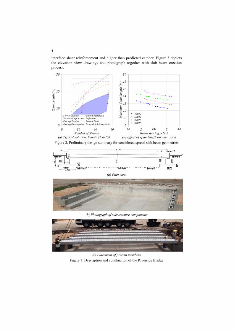
interface shear reinforcement and higher than predicted camber. Figure 3 depicts
the elevation view drawings and photograph together with slab beam erection
process.
(a) Typical solution domain (5SB15) (b) Effect of span length on max. span
Figure 2. Preliminary design summary for considered spread slab beam geometries
(a) Plan view
(b) Photograph of substructure components
(c) Placement of precast members
Figure 3. Description and construction of the Riverside Bridge

5
The bridge was instrumented to better observe the behaviour under service
loading. One objective was to evaluate the shear LLDFs and was achieved by
placing load cells at both ends of each slab beam. Another important response for
designing the prestressed girders is the distribution of moments between girders.
The maximum moment reactions was calculated from the data measured by strain
gages attached at midspan of each beam and also by measuring the deflection curve
along the length of each beam using a total of 40 string potentiometer. In addition a
total of eight accelerometers were attached on the bottom surface of the slab beams
to capture dynamic properties of the bridge.
For the static tests the vehicles (a dump truck or a water tanker) were placed at
the critical position for creating the maximum moment effect, and they were placed
at a member depth away from the centerline of the bearing pads for creating the
maximum shear effect. Transverse positions were determined for creating critical
loading when two lanes are loaded. Two alignment couples were defined by
considering the minimum distance between vehicles as 1.2 m. A total of four
transverse alignments were loaded where one alignment couple created the critical
loading for an exterior girder and the other created critical loading for an interior
girder. Figure 4 presents moment and shear LLDFs when the exterior girder critical
alignments are loaded with dump trucks.
Experimental shear LLDFs for both interior and exterior girders were about 5
percent higher when the Bridge was loaded with the rear axle of the water tanker
compared to the dump truck loading. This may be due to more concentrated loading
achieved with the water tanker. Experimental moment LLDFs were similar for both
the dump truck and the water tanker loadings.
The observed bridge responses under dynamic loads were larger when compared
to the static counterparts. Evidently, for short-span bridges, the dynamic impact may
exceed the AASHTO LRFD Specifications [2] design value of 33 percent.
However, the observed impact depended upon the position of the approach bump
as well as the dynamic characteristics of the vehicle and the bridge.
(a) Moment LLDF (b) Shear LLDF
Figure 4. LLDFs measured during static loading of the Riverside Bridge
6
3 Computational Modelling
3.1 Model Descriptions
The experimental results obtained from the field testing of the Riverside Bridge
were used to investigate different modelling approaches. These modelling
techniques include, grillage analysis and the finite element method (FEM). Moment
and shear predictions from computational models were compared with
experimentally obtained values. The FEM modelling technique, which gave good
agreement with the test results, was then utilized for further investigation in the
parametric study for developing moment and shear LDF formulas.
Grillage analysis was first introduced by Lightfoot and Sawko [6] and provides
a simplified approach by reducing the number of degrees of freedom. Grillage
analysis is historically the most basic type of computational modelling technique
for analysing slab and beam bridges. This method idealizes the bridge
superstructure by assuming that it may be represented by a mesh of frame elements
in each of the two orthogonal directions. The Riverside Bridge grillage model was
developed following the guidelines provided by Hambly [7] and Zokaie et al. [8].
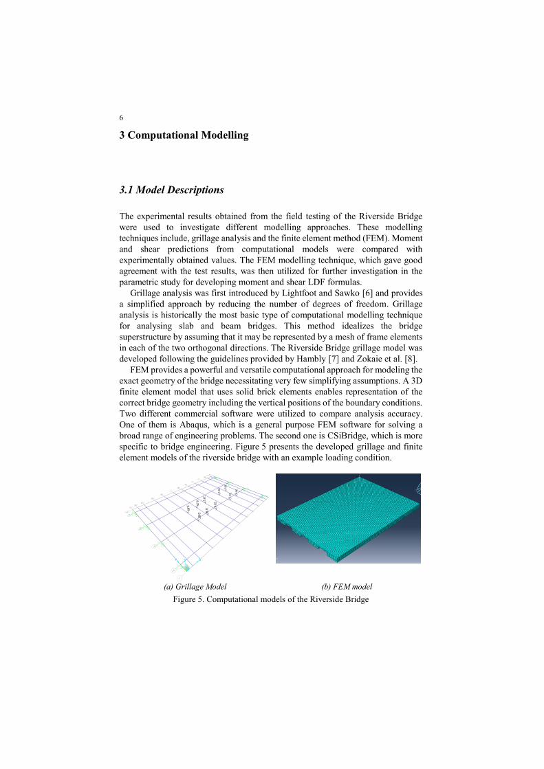
FEM provides a powerful and versatile computational approach for modeling the
exact geometry of the bridge necessitating very few simplifying assumptions. A 3D
finite element model that uses solid brick elements enables representation of the
correct bridge geometry including the vertical positions of the boundary conditions.
Two different commercial software were utilized to compare analysis accuracy.
One of them is Abaqus, which is a general purpose FEM software for solving a
broad range of engineering problems. The second one is CSiBridge, which is more
specific to bridge engineering. Figure 5 presents the developed grillage and finite
element models of the riverside bridge with an example loading condition.
(a) Grillage Model (b) FEM model
Figure 5. Computational models of the Riverside Bridge
7
Three-dimensional eight-node solid brick elements with three degrees of
freedom at each node were utilized for the FEM models. The slab beams were seated
on bearing pads at the support locations. One sample bearing pad was tested under
cyclic axial load and the vertical stiffness at the supports were assigned based on
test results. The lateral stiffness of these pads were calculated based on the
manufacturer provided shear modulus. The rotational stiffness were taken as zero
due to the load cell setup, which is very close to ideal pin support conditions.
3.1 Results of Computational Analysis
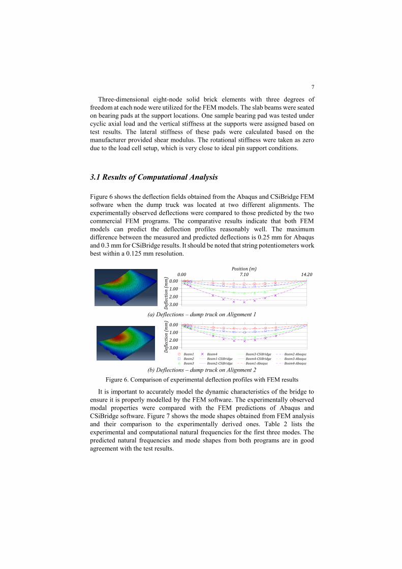
Figure 6 shows the deflection fields obtained from the Abaqus and CSiBridge FEM
software when the dump truck was located at two different alignments. The
experimentally observed deflections were compared to those predicted by the two
commercial FEM programs. The comparative results indicate that both FEM
models can predict the deflection profiles reasonably well. The maximum
difference between the measured and predicted deflections is 0.25 mm for Abaqus
and 0.3 mm for CSiBridge results. It should be noted that string potentiometers work
best within a 0.125 mm resolution.
(a) Deflections – dump truck on Alignment 1
(b) Deflections – dump truck on Alignment 2
Figure 6. Comparison of experimental deflection profiles with FEM results
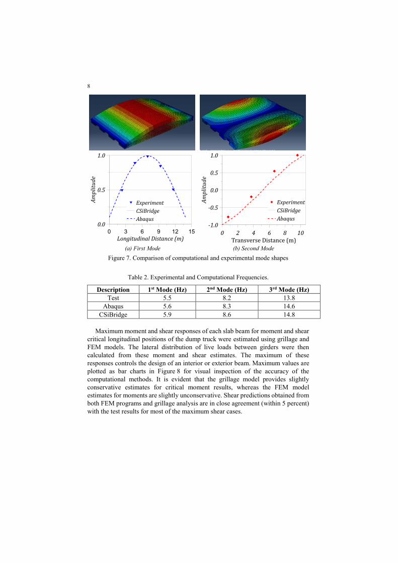
It is important to accurately model the dynamic characteristics of the bridge to
ensure it is properly modelled by the FEM software. The experimentally observed
modal properties were compared with the FEM predictions of Abaqus and
CSiBridge software. Figure 7 shows the mode shapes obtained from FEM analysis
and their comparison to the experimentally derived ones. Table 2 lists the
experimental and computational natural frequencies for the first three modes. The
predicted natural frequencies and mode shapes from both programs are in good
agreement with the test results.
8
(a) First Mode (b) Second Mode
Figure 7. Comparison of computational and experimental mode shapes
Table 2. Experimental and Computational Frequencies.
Description 1st Mode (Hz) 2nd Mode (Hz) 3rd Mode (Hz)
Test 5.5 8.2 13.8
Abaqus 5.6 8.3 14.6
CSiBridge 5.9 8.6 14.8
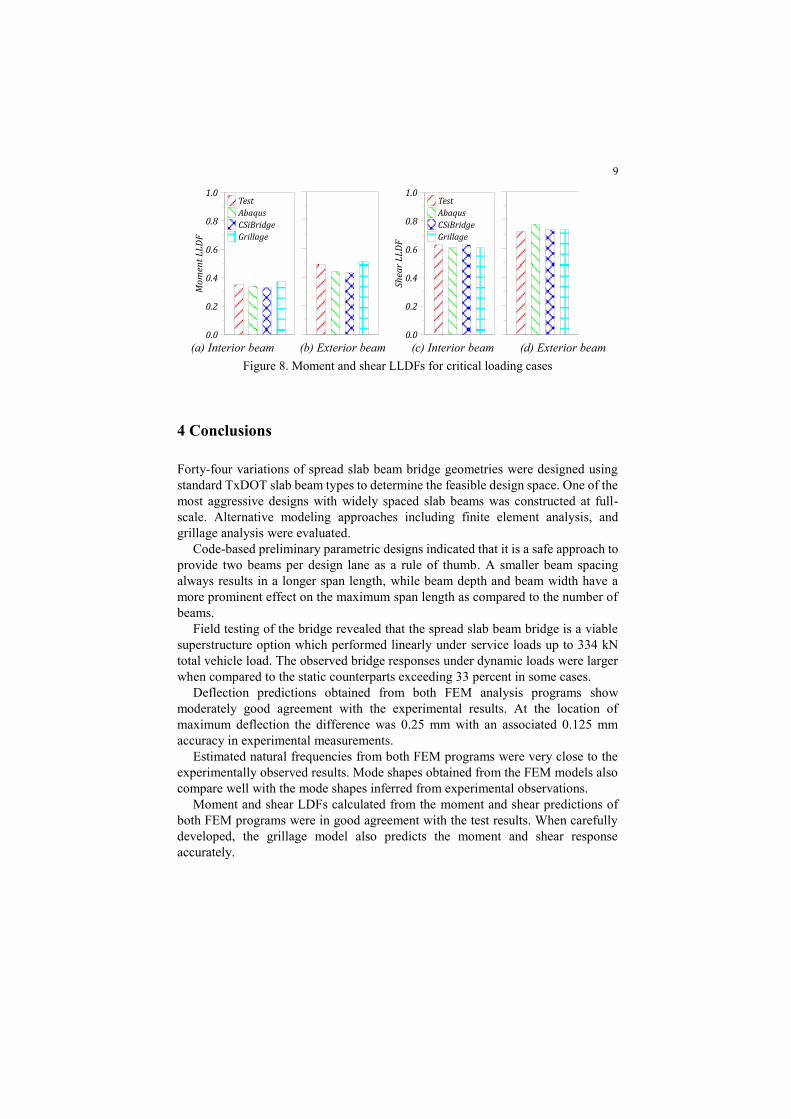
Maximum moment and shear responses of each slab beam for moment and shear
critical longitudinal positions of the dump truck were estimated using grillage and
FEM models. The lateral distribution of live loads between girders were then
calculated from these moment and shear estimates. The maximum of these
responses controls the design of an interior or exterior beam. Maximum values are
plotted as bar charts in Figure 8 for visual inspection of the accuracy of the
computational methods. It is evident that the grillage model provides slightly
conservative estimates for critical moment results, whereas the FEM model
estimates for moments are slightly unconservative. Shear predictions obtained from
both FEM programs and grillage analysis are in close agreement (within 5 percent)
with the test results for most of the maximum shear cases.
9
(a) Interior beam (b) Exterior beam (c) Interior beam (d) Exterior beam
Figure 8. Moment and shear LLDFs for critical loading cases
4 Conclusions
Forty-four variations of spread slab beam bridge geometries were designed using
standard TxDOT slab beam types to determine the feasible design space. One of the
most aggressive designs with widely spaced slab beams was constructed at full-
scale. Alternative modeling approaches including finite element analysis, and
grillage analysis were evaluated.
Code-based preliminary parametric designs indicated that it is a safe approach to
provide two beams per design lane as a rule of thumb. A smaller beam spacing
always results in a longer span length, while beam depth and beam width have a
more prominent effect on the maximum span length as compared to the number of
beams.
Field testing of the bridge revealed that the spread slab beam bridge is a viable
superstructure option which performed linearly under service loads up to 334 kN
total vehicle load. The observed bridge responses under dynamic loads were larger
when compared to the static counterparts exceeding 33 percent in some cases.
Deflection predictions obtained from both FEM analysis programs show
moderately good agreement with the experimental results. At the location of
maximum deflection the difference was 0.25 mm with an associated 0.125 mm
accuracy in experimental measurements.
Estimated natural frequencies from both FEM programs were very close to the
experimentally observed results. Mode shapes obtained from the FEM models also
compare well with the mode shapes inferred from experimental observations.
Moment and shear LDFs calculated from the moment and shear predictions of
both FEM programs were in good agreement with the test results. When carefully
developed, the grillage model also predicts the moment and shear response
accurately.

10
Acknowledgments This research was supported by TxDOT and FHWA as part
of TxDOT Project 0-6722. The authors are grateful to the TxDOT project
monitoring committee who provided invaluable assistance. The support of the
Texas A&M Transportation Institute (TTI) is also greatly appreciated, along with
all the students and the TTI Riverside construction crew who helped with the
construction and testing.
References
1. Panak, J.J., Economical Precast Concrete Bridges, in FHWA-TX-83-08+226-1F Final Rpt. 1982,
FHWA and Texas Department of Highway & Public Transportation: Austin, TX.
2. AASHTO LRFD Bridge Design Specifications. 2012, American Association of State Highway and
Transportation Officials (AASHTO): Washington, DC.
3. TxDOT Bridge Design Manual - LRFD. 2013a, Texas Department of Transportation:
http://onlinemanuals.txdot.gov/txdotmanuals/lrf/lrf.pdf.
4. Terzioglu, T., Behavior and Design of Spread Prestressed Concrete Slab Beam Bridges, in Civil
Engineering. 2015, Texas A&M University: College Station, TX. p. 406.
5. Hueste, M.D., J.B. Mander, T. Terzioglu, D. Jiang, and J. Petersen-Gauthier, Spread Prestressed
Concrete Slab Beam Bridges, in Research Report No. FHWA/TX-14/0 6722-1. 2015, Texas A&M
Transportation Institute and Texas Department of Transportation.
6. Lightfoot, E. and F. Sawko, Structural Frame Analysis by Electronic Computer: Grid Frameworks
by Generalised Slope Deflection. Engineering, 1959(187): p. 18-20.
7. Hambly, E.C., Grillage Analysis Applied to Cellular Bridge Decks. The structural engineer, 1975.
53(7): p. 267-276.
8. Zokaie, T., R.A. Imbsen, and T.A. Osterkamp, Distribution of Wheel Loads on Highway Bridges,
in NCHRP Project Report 12-26. 1991, Transportation Research Board: Washington, DC.